

Page 1

DC Power Supply
GPD-2303S/3303S/4303S
Service MANUAL
GW INSTEK PART NO.
ISO-9001 CERTIFIED MANUFACTURER
Page 2

This manual contains proprietary information which is protected by copyright. All rights are reserved.
No part of this manual may be photocopied, reproduced or translated to another language without
prior written consent of Good Will Corporation.
The information in this manual was correct at the time of printing. However, Good Will continues to
improve its products and therefore reserves the right to change the specifications, equipment, and
maintenance procedures at any time without notice.
Windows is a registered trademark of Microsoft Corporation in the United States and other countries.
Good Will Instrument Co., Ltd.
No.7-1, Jhongsing Road., Tucheng Dist., New Taipei City 236, Taiwan .
Page 3

Table of Contents
Table of Contents
Safety Instructions ..............................................6
How to Use This Manual ......................................9
Service Operation List ................................................................ 9
Summary of Chapters .............................................................. 10
GPD-x303S Series Overview .............................. 12
Front Panel ............................................................................. 13
Rear Panel .............................................................................. 13
Operation Theory .................................................................... 14
CV/CC Crossover Characteristics .............................................. 15
Specifications ......................................................................... 16
Options .................................................................................... 17
Preparing For Service Operations ....................... 18
Package Contents .................................................................... 18
Setting Up the Power Supply .................................................... 19
Powering up the power supply ................................................. 19
Connecting the load cables ...................................................... 19
Turning on the output .............................................................. 20
List of Equipments .................................................................. 21
Calibration ....................................................... 23
Preparing for Calibration ......................................................... 23
Calibration Log ....................................................................... 25
GPD-x303S(CH1/CH2) ............................................................. 25
GPD-4303S(CH3/CH4) ............................................................. 25
Calibrating CH1/2 Output Voltage /Current ............................... 27
Calibrating CH3/4 Output voltage/Current(4303S) .................... 33
Verification ...................................................... 37
Preparing for Verification ......................................................... 38
Verification Log ....................................................................... 39
Verifying High Voltage Insulation ............................................. 42
Verifying Output Voltage Accuracy ........................................... 43
3
Page 4

GPD-3303 Series Service Manual
Verifying Output Current Accuracy ........................................... 46
Verifying CH3 Overload (3303S) ............................................... 48
Verifying Voltage Load Regulation ............................................ 49
Verifying Voltage Line Regulation ............................................. 54
Verifying Current Load Regulation ............................................ 55
Verifying Ripple Voltage .......................................................... 58
Updating the Firmware ...................................... 62
Preparing for Firmware Update ................................................. 62
Installing the USB Driver to the PC............................................ 63
Installing the bootloader software to the PC ............................ 64
Updating the Firmware ............................................................. 67
Replacing the Fuse ........................................... 69
Replacing the Primary Fuse ...................................................... 69
Replacing the Secondary Fuses ................................................. 70
Disassembling the Power Supply ........................ 72
Outer Casing & Supporting Bar ................................................. 72
Front Panel ............................................................................. 74
Power Supply PCB .................................................................... 76
GPD-x303S PCB & Circuit Diagram ..................... 77
Overview ................................................................................ 78
GPD-x303S Control PCB ........................................................... 79
GPD-x303S control PCB layout top side layout......................... 79
GPD-x303S control PCB layout bottom side layout .................. 80
GPD-x303S control PCB circuit diagram 1/4 ............................ 81
GPD-x303S control PCB circuit diagram 2/4 ............................ 82
GPD-x303S control PCB circuit diagram 3/4 ............................ 83
GPD-x303S control PCB circuit diagram 4/4 ............................ 84
GPD-x303S Display PCB ........................................................... 85
GPD-x303S display PCB Top side layout .................................. 85
GPD-x303S display PCB circuit diagram ................................... 86
GPD-x303S Power Supply PCB .................................................. 87
GPD-x303S power supply PCB layout (CH1/CH2/CH3) ............. 87
GPD-x303S power supply PCB circuit diagram
(CH1/CH2/CH3/CH4) ............................................................... 88
GPD-x303S Power Switch PCB, CH4 Power PCB, AC Selector PCB, USB
Interface PCB .......................................................................... 89
4
Page 5

Table of Contents
Parts List ......................................................... 90
Outer Casing ........................................................................... 91
Internal Structures .................................................................. 93
Front Panel ............................................................................. 94
PCB Mount Parts: GPD-2303S ................................................... 95
PCB Mount Parts: GPD-3303S ................................................. 100
PCB Mount Parts: GPD-4303S ................................................. 107
Appendix ....................................................... 114
Declaration of Conformity ...................................................... 114
Index ................................................................................... 115
5
Page 6
GPD-3303 Series Service Manual
WARNING
Warning: Identifies conditions or practices that could
result in injury or loss of life.
CAUTION
Caution: Identifies conditions or practices that could
result in damage to the instrument or to other objects.
DANGER High Voltage
Attention: Refer to the Manual
Protective Conductor Terminal
Earth (ground) Terminal
General guidelines
CAUTION
Do not place any heavy object on the GPD-x303S series.
Avoid severe impacts or rough handling that leads to
damaging the GPD-x303S series.
Do not discharge static electricity to the GPD-x303S
series.
Do not block or obstruct the cooling fan vent opening.
Do not perform measurement at circuits directly.
connected to Mains (see note below).
Do not disassemble the GPD-x303S series unless you are
qualified as service personnel.
SAFETY INSTRUCTIONS
This chapter contains important safety instructions that you
should follow when operating the instrument and when
keeping it in storage. Read the following before operating
this instrument to ensure your safety and to keep the
instrument in best condition.
Safety Symbols
These safety symbols may appear in this manual or on the instrument.
Safety Guidelines
(Continues to the next page)
6
Page 7

Safety Instructions{
(Note) EN 61010-1:2001 specifies the measurement categories and their
requirements as follows. This instrument falls under category II.
Measurement category IV is for measurement performed at the source of
low-voltage installation. Measurement category III is for measurement
performed in the building installation. Measurement category II is for
measurement performed on the circuits directly connected to the low voltage
installation.
Power supply
WARNING
AC Input voltage: 100V/120V/220V/230V ±10%, 50/60Hz
Connect the protective grounding conductor of the AC
power cord to an earth ground, to avoid electrical shock.
Fuse
WARNING
Fuse type: 100V/120V: T6.3A/250V, 220V/230V:
T3.15A/250V
Make sure the correct type of fuse is installed before
power up.
To ensure fire protection, replace the fuse only with the
specified type and rating.
Disconnect the power cord before fuse replacement.
Make sure the cause of fuse blowout is fixed before fuse
replacement.
Cleaning the
instrument
Disconnect the power cord before cleaning.
Use a soft cloth dampened in a solution of mild detergent
and water. Do not spray any liquid.
Do not use chemicals or cleaners containing harsh
products such as benzene, toluene, xylene, and acetone.
Operating
environment
Location: Indoor, no direct sunlight, dust free, almost
non-conductive pollution (note below)
Relative Humidity: < 80%
Altitude: < 2000m
Temperature: 0°C to 40°C
(Note) EN 61010-1:2001 specifies the pollution degrees and their requirements as
follows. This instrument falls under degree 2.
Pollution is defined as “addition of foreign matter, solid, liquid, or gaseous
(ionized gases), that may produce a reduction in dielectric strength or surface
resistivity”.
Pollution degree 1: No pollution or only dry, non-conductive pollution occurs. The
pollution has no influence.
Pollution degree 2: Normally only non-conductive pollution occurs. Occasionally,
however, a temporary conductivity caused by condensation can be expected.
Pollution degree 3: Conductive pollution occurs, or dry, non-conductive pollution
occurs which becomes conductive due to the expected condensation. In such
conditions, while the equipment is normally protected against exposure to direct
sunlight, precipitation, and strong draughts, neither temperature nor humidity is
controlled.
7
Page 8

GPD-3303 Series Service Manual
Storage
environment
Location: Indoor
Relative Humidity: < 70%
Temperature: −10°C to 70°C
Green/ Yellow:
Earth
Blue:
Neutral
Brown:
Live (Phase)
Power cord for the United Kingdom
When using the instrument in the United Kingdom, make sure the power cord
meets the following safety instructions.
NOTE: This lead / appliance must only be wired by competent persons
WARNING: THIS APPLIANCE MUST BE EARTHED
IMPORTANT: The wires in this lead are coloured in accordance with the following code:
As the colours of the wires in mains leads may not correspond with the colour markings identified
in your plug/appliance, proceed as follows:
The wire which is coloured Green & Yellow must be connected to the Earth terminal marked with
the letter E or by the earth symbol or coloured Green or Green & Yellow.
The wire which is coloured Blue must be connected to the terminal which is marked with the letter
N or coloured Blue or Black.
The wire which is coloured Brown must be connected to the terminal marked with the letter L or P
or coloured Brown or Red.
If in doubt, consult the instructions provided with the equipment or contact the supplier.
This cable/appliance should be protected by a suitably rated and approved HBC mains fuse: refer
to the rating information on the equipment and/or user instructions for details. As a guide, cable
of 0.75mm2 should be protected by a 3A or 5A fuse. Larger conductors would normally require
13A types, depending on the connection method used.
Any moulded mains connector that requires removal /replacement must be destroyed by removal
of any fuse & fuse carrier and disposed of immediately, as a plug with bared wires is hazardous if
a engaged in live socket. Any re-wiring must be carried out in accordance with the information
detailed on this label.
8
Page 9

How to Use This Manual{
I want to…
Go to…
Page
Verify the
specifications
The Verification chapter. We recommend you
to verify all listed items at once.
Page37
Calibrate the
power supply
The Calibration chapter. To ensure accuracy,
calibrate all listed items at once. We also
recommend you to verify the specifications
afterward.
Page23
Update the
firmware
The Firmware Update chapter.
Page62
Replace the fuse
The Fuse Replacement chapter.
Page69
Examine the
circuits
The PCB & Circuit Diagrams chapter.
Page77
Order a part
The Parts List chapter. Look up the parts list
and find the part name, part number, and
quantity. For PCB mounted parts, look into
the PCB & Circuit Diagrams chapter too.
Page90
HOW TO USE THIS MANUAL
If you are not sure what type of service operation you
should choose, read the Service Operation List section and
find the chapter which suits your needs. The Summary of
Each Chapter section gives you an overview of this service
manual’s contents.
To find a place in the manual which deals with a specific
keyword, refer to the Index chapter at the end of this service
manual.
Service Operation List
See the following list, decide which operation you might need, and jump to the
introduced chapter.
9
Page 10

GPD-3303 Series Service Manual
Safety Instructions
(page6)
Describes the important safety instructions that should be
followed before, during, and after operating the power
supply.
How to Use This
Manual (page9)
Provides the summary of each chapter in this service
manual and shows where to read for various service
operations.
List of service operations
Summary of chapters
GPD-x303S series
Overview
(page12)
Helps service engineers become familiar with the power
supply. Panel overview and specifications contain all
performance data and functionalities. Operation theory
shows how the power supply is internally structured.
Front and Rear panel
Operation theory
CV/CC crossover characteristics
Specifications
Preparation
(page18)
Describes how to set up the power supply to prepare for
various service operations. Also lists all the required tools.
Package contents
Setting up the power supply
List of equipments for various service operations
Calibration
(page23)
Describes how to calibrate the power supply using its
automatic calibration function.
GPD-2303S/3303S/4303S:
CH1 output voltage
CH2 output voltage
CH1 output current
CH2 output current
GPD-4303S:
CH3 output voltage
CH4 output voltage
CH3 output current
CH4 output current
Summary of Chapters
This document consists of the following chapters.
10
Page 11

How to Use This Manual{
Verification
(page37)
Describes how to verify the power supply’s major
functionalities, covering the following items:
High voltage insulation
Output current accuracy
Voltage load regulation
Current load regulation
Output voltage accuracy
CH3 overload
Voltage line regulation
Voltage ripple verification
Firmware upgrade
(page62)
Describes how to upgrade the firmware.
Fuse replacement
(page69)
Describes how to replace the fuses.
Main fuse (stored in the power cord socket)
Sub fuses (mounted on the power supply PCB)
Disassembly
(page72)
Shows how to remove major modules from the power
supply.
Outer casing and supporting bar
Front panel
Power supply PCB
GPD-x303S PCB &
Circuit diagrams
(page77)
Shows the PCB layout diagrams and circuit diagrams.
Control PCB
Display PCB
Power supply PCB
AC selector PCB
Power switch PCB
USB interface PCB
CH4 Power PCB(for 4303S)
Parts List
(page90)
Shows the diagrams and replacement parts list for the
mechanical components used in the power supply.
Outer casing
Front panel
Internal structures
GPD-x303S PCB parts
Appendix
(page114)
Declaration of conformity
Index
11
Page 12

GPD-3303 Series Service Manual
GPD-X303S SERIES OVERVIEW
The Overview chapter helps you become familiar with the
power supply. The front and rear panel diagrams introduce
how the panel items are called. The operation theory
describes the power supply’s internal structure, and how
the signals are processed. The specifications section lists
technical details of the power supply series.
Front Panel ............................................................................. 13
Rear Panel .............................................................................. 13
Operation Theory .................................................................... 14
CV/CC Crossover Characteristics .............................................. 15
Specifications ......................................................................... 16
Options .................................................................................... 17
12
Page 13
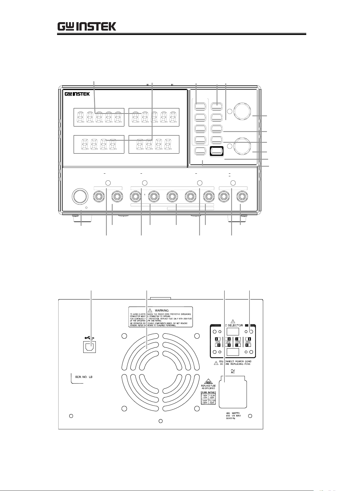
GPD-x303S Series Overview{
COARSE/FINE
FINE
COARSE/FINE
FINE
BEEP
UNLOCK
: Long Push
RECALL /
MEMORY
SAVE
VOLTAGE
Push
Push
CURRENT
1
2
3
4
LOCK
CH1/3
CH2/4
OUTPUT
/INDEP
PARA
/INDEP
SER
DC Power Supply
V
A
V
A
CH4 CH1
GPD-4303S
CH2 CH3
C.V. C.C. PAR. C.V. C.C.
POWER
CH3
0 30V , 3A 0 30V , 3A
CH2 GND CH1
SLAVE MASTER
SERIES
OUTPUT COM
OUTPUT
PARA
CH4
C.C.C.V.C.C.C.V.
0 5V , 1A 0 5V , 3A
5 10V , 1A
+
+
USB Connector AC SelectorCooling Fan
Power Cord /
Fuse Socket
VoltMeter AmpMeter Memory key CH1(3) CH2(4)/Beep key
Power SW CH4 Output CH2 Output GND Terminal CH2 Output CH4 Output
CH4 CV/CC CH2 CV/CC/PAR CH1 CV/CC CH3 CV/CC
Indicator Indicator Indicator Indicator
Voltage Knobs y
Parallel key
Series key
Lock key
Output key
Current
Front Panel
Rear Panel
13
Page 14
GPD-3303 Series Service Manual
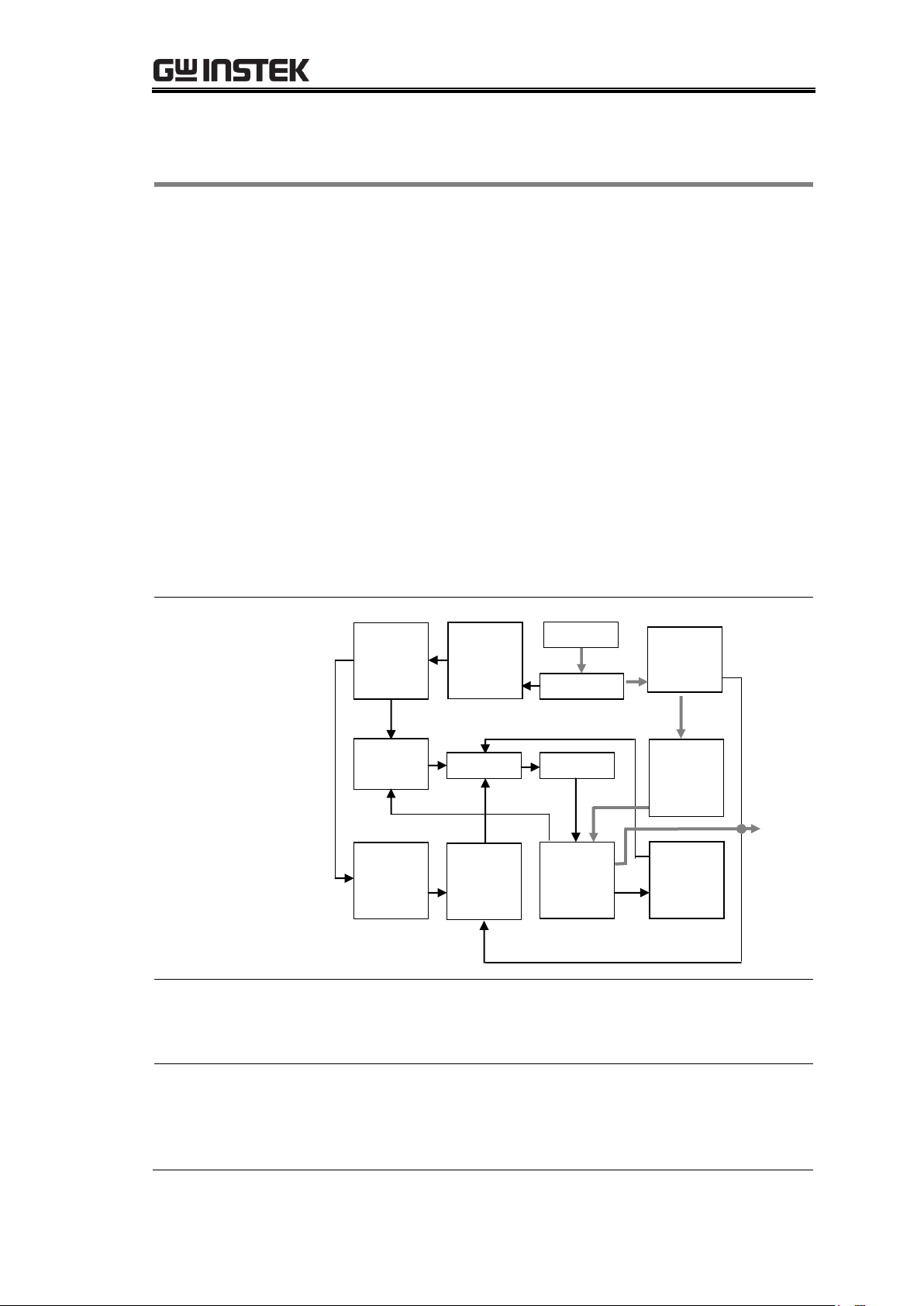
Overview
The power supply consists of the following modules.
AC input circuit
Transformer
Bias power supply including rectifier, filter,
pre-regulator and reference voltage source
Main regulator circuit including the main rectifier and
filter, series regulator, current comparator, voltage
comparator, reference voltage amplifier, remote device
and relay control circuit
The below block diagram shows the circuit arrangement.
The single phase input power is connected to the
transformer through the input circuit. Details of each part
are described after the block diagram.
For more details regarding the circuits, see page77
Block diagram
(Example for CH2)
Auxiliary Rectifier
The auxiliary rectifiers provide bias voltage filtered by the
capacitors C102 and C103, for the pre-regulators U101 and
U102. They provide a regulated voltage for other modules.
Main Rectifier
The main rectifier is a full wave bridge rectifier. It provides
the power after the rectifier is filtered by the capacitor C101,
and then regulated via a series-wound regulator, which is
finally delivered to the output terminal.
Reference
Voltage
Source
Auxiliary
Rectifier
& Filter
AC Input
Transformer
Relay
Control
Current
Comparat
“OR” Gate
Amplifier
Main
Rectifier
Compar
& Filter
Voltage
Voltage
Series
Instant
Protection
O/P
Amplifier Comparator Regulator Over Load
Operation Theory
14
Page 15
GPD-x303S Series Overview{
Current Limiter
U104 acts as a current limiter. When the current is over
predetermined rating, U104 is activated and decreases the
current. U208 provides a reference voltage. U206 is the
inverter amplifier. U103 is a comparator amplifier which
compares reference voltage and feedback voltage, and then
delivers to Q101, Q102, which then calibrates the output
voltage.
Overload
When the unit is overloaded, Q107 activates to control the
current magnitude of Q101, to limit the output current. The
relay control circuit controls the power dissipation in the
series-wound regulated circuit.
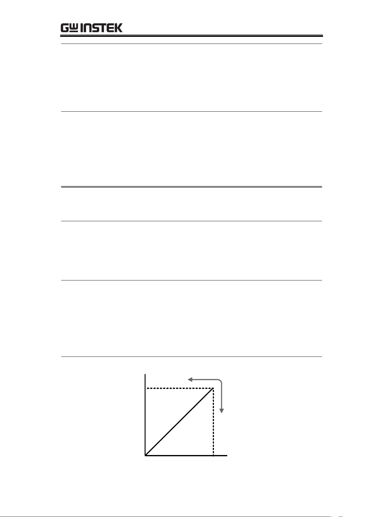
Background
The GPD-x303S series automatically switches between
constant voltage mode (CV) and constant current mode
(CC), according to load condition.
CV mode
When the current level is smaller than the output setting,
the GPD-x303S series operates in Constant Voltage mode.
The indicator on the front panel turns green (C.V.) The
Voltage level is kept at the setting and the Current level
fluctuates according to the load condition until it reaches
the output current setting.
CC mode
When the current level reaches the output setting, the
GPD-x303S series starts operating in Constant Current
mode. The indicator on the front panel turns red (C.C.) The
Current level is kept at the setting but the Voltage level
becomes lower than the setting, in order to suppress the
output power level from overload. When the current level
becomes lower than the setting, the GPD-x303S series goes
back to the Constant Voltage mode.
Diagram
Vmax
Imax
Constant
Voltage
Constant
Current
Vout
Iout
CV/CC Crossover Characteristics
15
Page 16

GPD-3303 Series Service Manual
Output Ratings
CH1/CH2 Indep.
0 to 30V / 0 to 3A
CH1/CH2 Series
0 to 60V / 0 to 3A
CH1/CH2 Parallel
0 to 30V / 0 to 6A
CH3
2.5V/3.3V/5.0V, 0 ~ 3A(3303S)
0~5V,0~3A / 5.001~10V,0~1A(4303S)
CH4
0~5V,0~1A
Voltage
Regulation
Line
≤ 0.01% + 3mV
Load
≤ 0.01% + 3mV (rating current ≤ 3A)
≤ 0.02% + 5mV (rating current > 3A)
Ripple & Noise
≤ 1mVrms (5Hz ~ 1MHz)
Recovery Time
≤ 100µs (50% load change, min load 0.5A)
Temp Coefficient
≤ 300ppm/°C
Current
Regulation
Line
≤ 0.2% + 3mA
Load
≤ 0.2% + 3mA
Ripple & Noise
≤ 3mArms
Tracking
Operation
Tracking Error
≤ 0.1% + 10mV of Master (0 to 30V)
(No Load, with load add load regulation
≤100mV)
Parallel Regulation
Line: ≤ 0.01% + 3mV
Load: ≤ 0.01% + 3mV (rating current ≤ 3A)
Load: ≤ 0.02% + 5mV (rating current > 3A)
Series Regulation
Line: ≤ 0.01% + 5mV, Load: ≤ 100mV
Meter
Resolution
Voltage: 1mV (0 to 30V)
Current: 1mA (0 to 3A)
A Meter
3.2A full scale, 4 digits 0.4" LED display
V Meter
32V full scale, 5 digits 0.4" LED display
Program Accuracy
± (0.03% of reading + 10mV)
± (0.3% of reading + 10mA)
Readback Accuracy
± (0.03% of reading + 10mV)
± (0.3% of reading + 10mA)
CH3 of 3303S
Output Voltage
2.5V/3.3V/5.0V, ±5%
Output Current
3A
Line Regulation
≤ 3mV
Load Regulation
≤ 5mV
Ripple & Noise
≤ 1mVrms (5Hz ~ 1MHz)
Insulation
Chassis and Terminal
20MΩ or above (DC 500V)
Chassis and Ground
30MΩ or above (DC 500V)
Operating
Environment
Indoor use, Altitude: ≤ 2000m
Ambient temperature 0 ~ 40°C
Relative humidity ≤ 80%
Storage
Environment
Ambient temperature –10 ~ 70°C
Relative humidity ≤ 70%
Power Source
AC 100V/120V/220V/230V±10%, 50/60Hz
Accessories
User manual x1
Test lead GTL-104A x 2
GTL-105A x 1(3303S); x 2(4303S)
(Europe) Test lead GTL-204 x 2
GTL-203 x 1 (3303S), x2(4303S)
Dimensions
210 (W) x 130 (H) x 265 (D) mm, Approx. 7kg
Specifications
The following specifications apply when the power supply is powered on for at
least 30 minutes within +20°C to +30°C.
16
Page 17

Options
USB cable
GTL-246
USB 2.0, Type A-B
GPD-x303S Series Overview{
17
Page 18

GPD-3303 Series Service Manual
Main unit
GPD-2303S, GPD-3303S, or GPD-4303S
Cables
(non-European
model)
GTL-104A x 2 (screw clip – alligator clip, maximum 10A)
GTL-105A x 1 (3303S), x2(4303S) (banana plug – alligator
clip, maximum 3A)
Power cord x 1
Cables (European
model)
GTL-201 x 1 (ground lead)
GTL-203 x 1 (3303S), x2(4303S) (test lead, maximum 3A)
GTL-204 x 2 (test lead, maximum 10A)
Power cord x 1
Manual
User manual x 1
PC interface
The following items are not included in the package but are
additionally required when using the GPD-x303S’s PC
interface functionalities.
USB cable x 1, Type A (host, PC) – Type B (slave, power
supply)
PREPARING FOR SERVICE OPERATIONS
The Preparation chapter describes the What (package
contents, required equipments) and How (setting up the
power supply) to prepare for various service operations.
Package Contents .................................................................... 18
Setting Up the Power Supply .................................................... 19
Powering up the power supply ................................................. 19
Connecting the load cables ...................................................... 19
Turning on the output .............................................................. 20
List of Equipments .................................................................. 21
Package Contents
The list below shows the components included in the purchased power supply.
18
Page 19
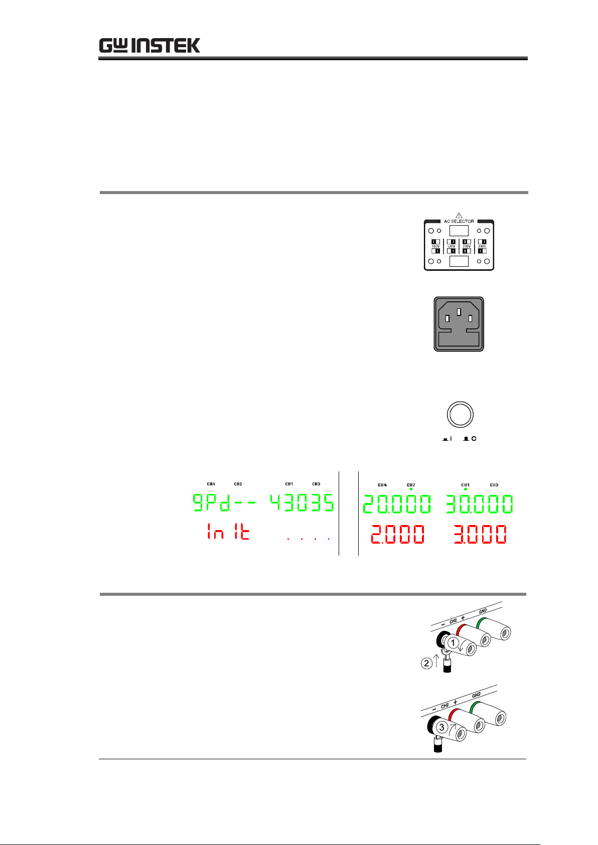
Preparing For Service Operations{
1. Selecting the
AC voltage
Before powering up the power
supply, select the AC input voltage
from the rear panel.
2. Connecting
the AC
power cord
Connect the AC power cord to the
rear panel socket.
3. Powering up
Press the Power switch to turn on the
power. The display shows the
initialization screen with the model
name, followed by the last recalled
settings. To turn off the power, press
the Power switch again.
(for example:4303S)
GTL-104A
1. Turn the terminal counterclockwise
and loosen the screw.
2. Insert the cable terminal.
3. Turn the terminal clockwise and
tighten the screw.
Setting Up the Power Supply
Follow these instructions to properly set up the power supply. Refer to the user
manual for more details regarding other operations.
Powering up the power supply
Connecting the load cables
19
Page 20
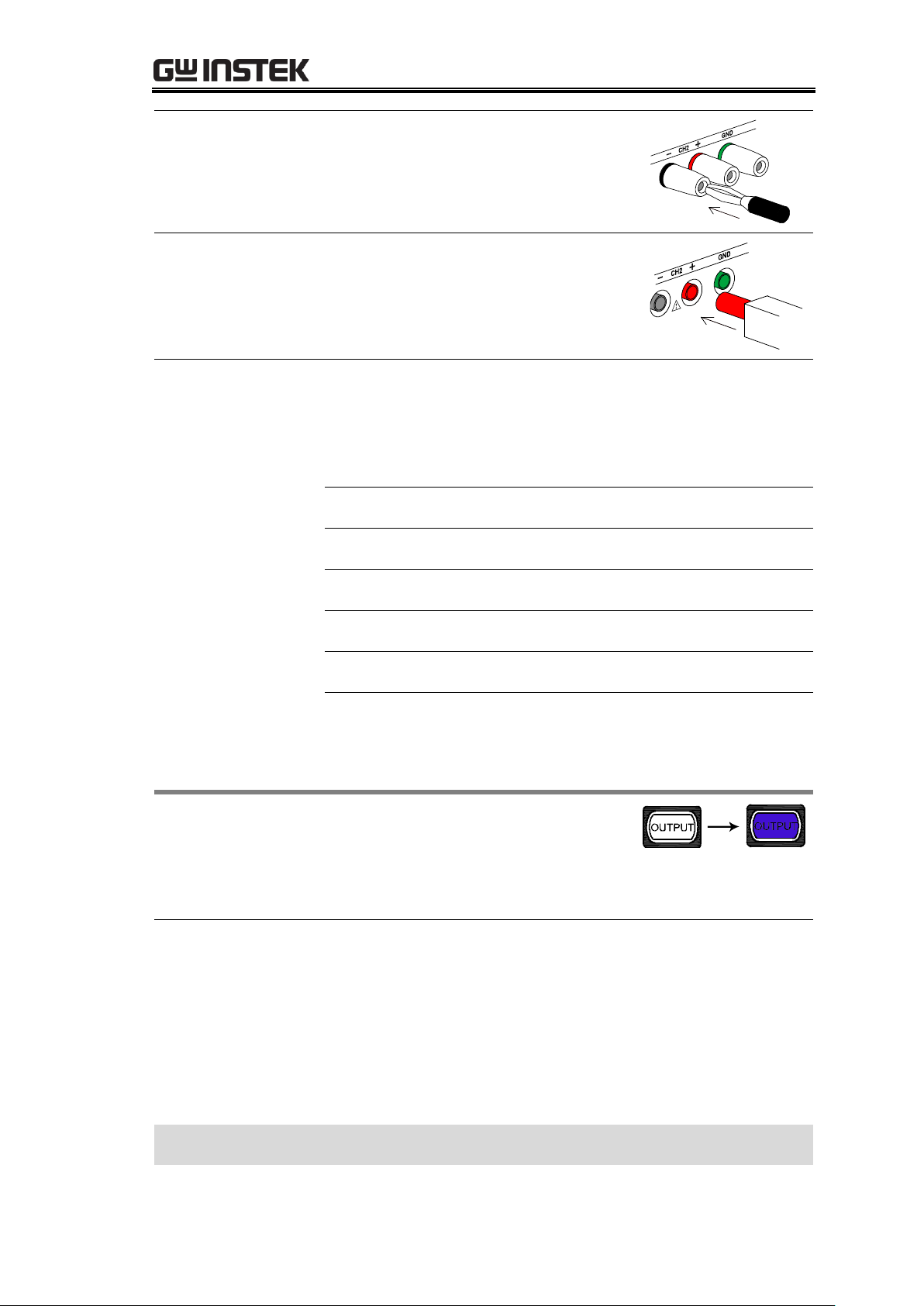
GPD-3303 Series Service Manual
GTL-105A
Insert the plug into the socket.
GTL-201, 203, 204
Insert the plug into the terminal.
Wire type
When using load cables other than the attached, make sure
they have enough current capacity for minimizing cable
loss and load line impedance. Voltage drop across a wire
should not excess 0.5V. The following list is the wire
current rating at 450A/cm2.
Wire size (AWG)
Maximum current (A)
20
2.5
18 4
16 6
14
10
12
16
Panel operation
Pressing the Output key turns on all
outputs.
The key LED also turns on. Pressing the Output key again
turns off the output and the key LED.
Automatic output
off
Any of the following actions automatically turns the output
off, since they might suddenly change the output level in
harmful ways.
Change the operation mode between independent /
tracking series / tracking parallel
Recalling other setups from the memory
Storing the setup into the memory
Setting up the power supply is completed
Turning on the output
20
Page 21

Preparing For Service Operations{
Item
Requirements
Used in
Digital multimeter
DCV accuracy: ± (0.005%+0.0006)
DCA accuracy: ± (0.1%)
Recommended model: Agilent-34401
All verification
items except for
insulation
Calibration
Multimeter – power
supply cable
DCV: ≥ 100V
DCA: ≥ 10A
DC electronic load
DCV: 3 – 60V
DCA: 6mA – 60A
Power: 1 – 300W
Recommended model: PEL-300
Load regulation,
line regulation,
ripple voltage
verification
Electronic load –
power supply cable
DCV: ≥ 100V
DCA: ≥ 10A
AC millivolt meter
DCV: 0.3mV – 60V
Frequency: 10Hz – 1MHz
Recommended model: GVT-417B
Ripple voltage
verification
Millivolt meter –
power supply cable
DCV: ≥ 100V
DCA: ≥ 10A
Hi-pot tester
DC power: 0.1 – 5kV
AC power: 0.1 – 5kV
Insulation resistance: 1 – 50MΩ
Recommended model: GPI-735A
Insulation
verification
Hi-pot tester –
power supply cable
Standard accessory attached to the
hi-pot tester
PC software
Terminal application for GPIB
commands
Firmware upgrade
PC
Windows2000 or XP based PC
Firmware upgrade
List of Equipments
Here is the list of all equipments used in the service operations.
21
Page 22

GPD-3303 Series Service Manual
USB cable
TypeA (host, PC) – TypeB (slave,
power supply)
Firmware upgrade
22
Page 23

Calibration{
Note
In order to ensure performance accuracy, we recommend
you to calibrate all items listed in this chapter at once.
Calibration item
GPD-2303S/3303S/4303S:
CH1 output voltage
CH2 output voltage
CH1 output current
CH2 output current
PARA output current
GPD-4303S:
CH3 output voltage
CH4 output voltage
CH3 output current
CH4 output current
When to calibrate
the power supply
When using the power supply in a new environment
After replacing one of the major internal modules, such
as the front panel or power supply PCB
Pre-calibration test
To make the calibration more effective, we recommend you
to run the following test beforehand.
Burn-in test: 4 hours, 45~47°C, RH 65%
CALIBRATION
The Calibration chapter describes how to calibrate the
power supply using its automatic calibration feature. We
recommend you to verify the specifications (page37) after
completing the calibrations.
Preparing for Calibration ......................................................... 23
Calibration Log ....................................................................... 25
GPD-x303S(CH1/CH2) ............................................................. 25
GPD-4303S(CH3/CH4) ............................................................. 25
Calibrating CH1/2 Output Voltage /Current ............................... 27
Calibrating CH3/4 Output voltage/Current(4303S) .................... 33
Preparing for Calibration
23
Page 24

GPD-3303 Series Service Manual
Calibration
environment
Location: Indoor, no direct sunlight, dust free
Relative Humidity: < 80%
Temperature: +20°C~+30°C
Warm-up time: ≥ 30 minutes
Calibration
equipments
Digital multimeter
Digital multimeter – power supply cable
For detailed requirements for the equipments, see page21.
24
Page 25

Calibration{
Model
GPD-2303S
GPD-3303S
GPD-4303S
Serial number
____________________
Date
Year___________
Month__________
Date___________
Verified by
Name____________________________
Company/Contact_________________________
Environment
Temperature______°C
Humidity______%
Range
DMM reading
Acceptance range
Pass/Fail
30V
_____________V
±0.3mV
Pass
Fail
0V
_____________V
Pass
Fail
Range
DMM reading
Acceptance range
Pass/Fail
30V
_____________V
±0.3mV
Pass
Fail
0V
_____________V
Pass
Fail
Range
DMM reading
Acceptance range
Pass/Fail
3.0A
____________A
±0.5mA
Pass
Fail
0A
____________A
Pass
Fail
Range
DMM reading
Acceptance range
Pass/Fail
3.0A
____________A
±0.5mA
Pass
Fail
0A
____________A
Pass
Fail
Range
DMM reading
Acceptance range
Pass/Fail
10V
_____________V
±0.3mV
Pass
Fail
0V
_____________V
Pass
Fail
Calibration Log
Print out these pages and record the results. Keep it with the power supply.
GPD-x303S(CH1/CH2)
CH1 output voltage
CH2 output voltage
CH1 output current
CH2 output current
GPD-4303S(CH3/CH4)
CH3 output voltage
25
Page 26

CH4 output voltage
Range
DMM reading
Acceptance range
Pass/Fail
5V
_____________V
±0.3mV
Pass
Fail
0V
_____________V
Pass
Fail
Range
DMM reading
Acceptance range
Pass/Fail
3.0A
____________A
±0.5mA
Pass
Fail
0A
____________A
Pass
Fail
Range
DMM reading
Acceptance range
Pass/Fail
1.0A
____________A
±0.5mA
Pass
Fail
0A
____________A
Pass
Fail
CH3 output current
CH4 output current
GPD-3303 Series Service Manual
26
Page 27
Calibration{
Accepted range
GPD-x303S
±0.3mV, ±0.5mA
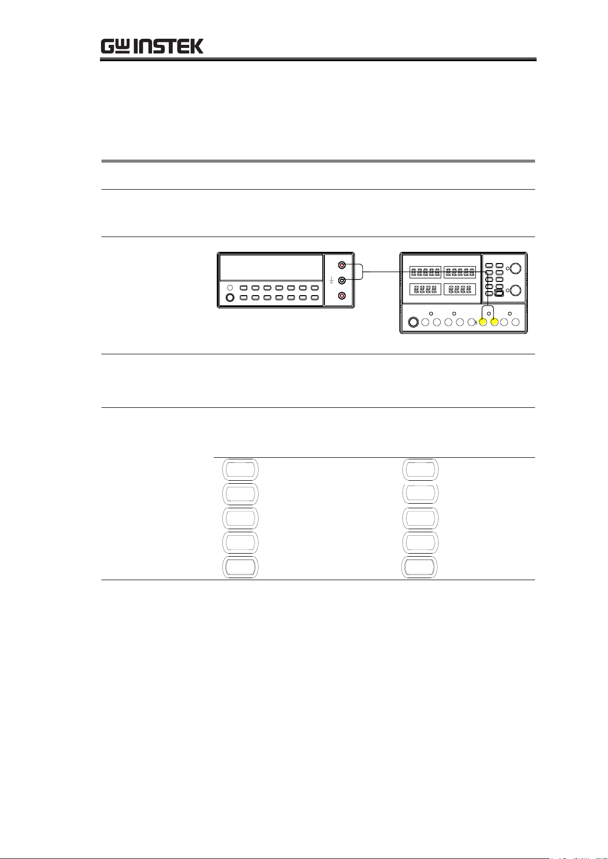
Equipment
Multimeter
Multimeter – Power supply cable
Connection
Digital Multimeter
V
A
CH1
Configurations
Power supply: N/A
Multimeter: DC voltage mode
Keypad Controls
When calibrating, the keypad keys are used as number
keys (0 to 9). The keypad keys correspond to the following
numbers.
1
1
CH1
6
2
2
CH2
7
3
3
/INDEP
PARA
8
4
4
/INDEP
SER
9
LOCK
5
OUTPUT
0
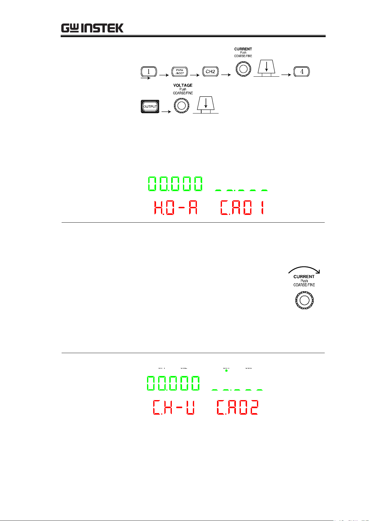
Entering the
calibration mode
1. Press the power supply’s front panel keys and knobs in
the following order.
(MEMORY) 1 key → PARA/INDEP key → CH2 key →
CURRENT knob → (MEMORY) 4 key → OUTPUT key
→ VOLTAGE knob
Calibrating CH1/2 Output Voltage/Current
27
Page 28
GPD-3303 Series Service Manual
(Do not turn the knob; press them)
2. The display enters into the calibration mode as in the
figure below (First into Burn in mode).
CH4 CH2 CH1 CH3
CA01:
Exit Burn in mode
The default value is 00.000 (you can check the last default
value by turning the VOLTAGE knob).
1. Input any digit from 1~9, press the
CURRENT knob to exit Burn in mode and
automatically go to the next step; (or turn
the CURRENT knob right to go the next
step, the same as below)
Input 0 (OUTPUT key), Press the
CURRENT knob to preserve Burn in mode
and automatically go to the next step;
2. Press the VOLTAGE knob twice to exit calibration
mode (same below)
CA02:
Calibrating CH1
output voltage (0V)
CH4 CH2 CH1 CH3
1. Read the voltage value of CH1 with the DMM (Unit is
V). Record the 3 digits after the decimal point.
28
Page 29
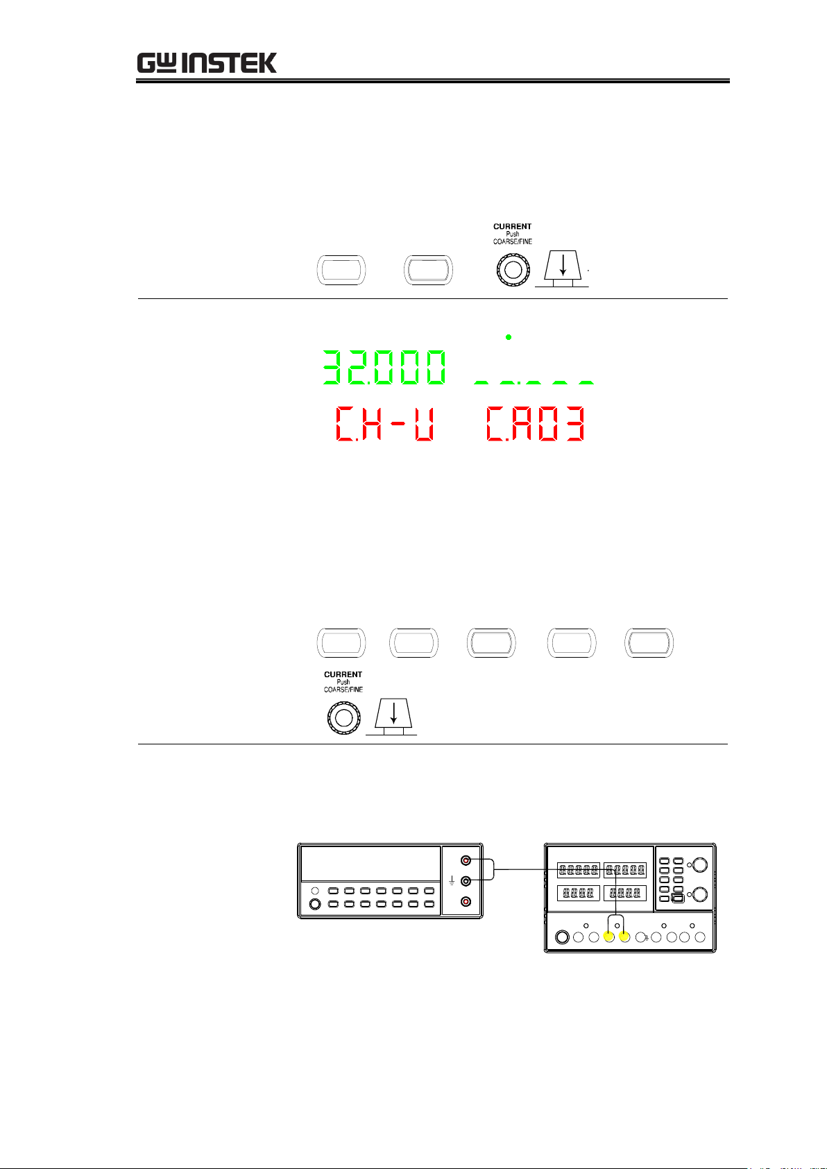
Calibration{
2. Input the DMM reading. For example for 0.065V, enter
digits “6” and”5”. The system will automatically save
and go to the next step. (No need to input decimal
point. The same process is shown below)
CH1
LOCK
CA03:
Calibrating CH1
output voltage
(30V)
CH4 CH2 CH1 CH3
1. Read the voltage value of the CH1 on the DMM (Unit is
V). Record the 3 digits after decimal point. For example
29.065V.
2. Input the reading of the DMM. For example,
29.065V.Enter digits “2”, “9”, “0”, “6” and “5”, the the
system will automatically save and enter to the next
step.
2
/INDEP
SER
OUTPUT
CH1
LOCK
Switching to CH2
output voltage
calibration
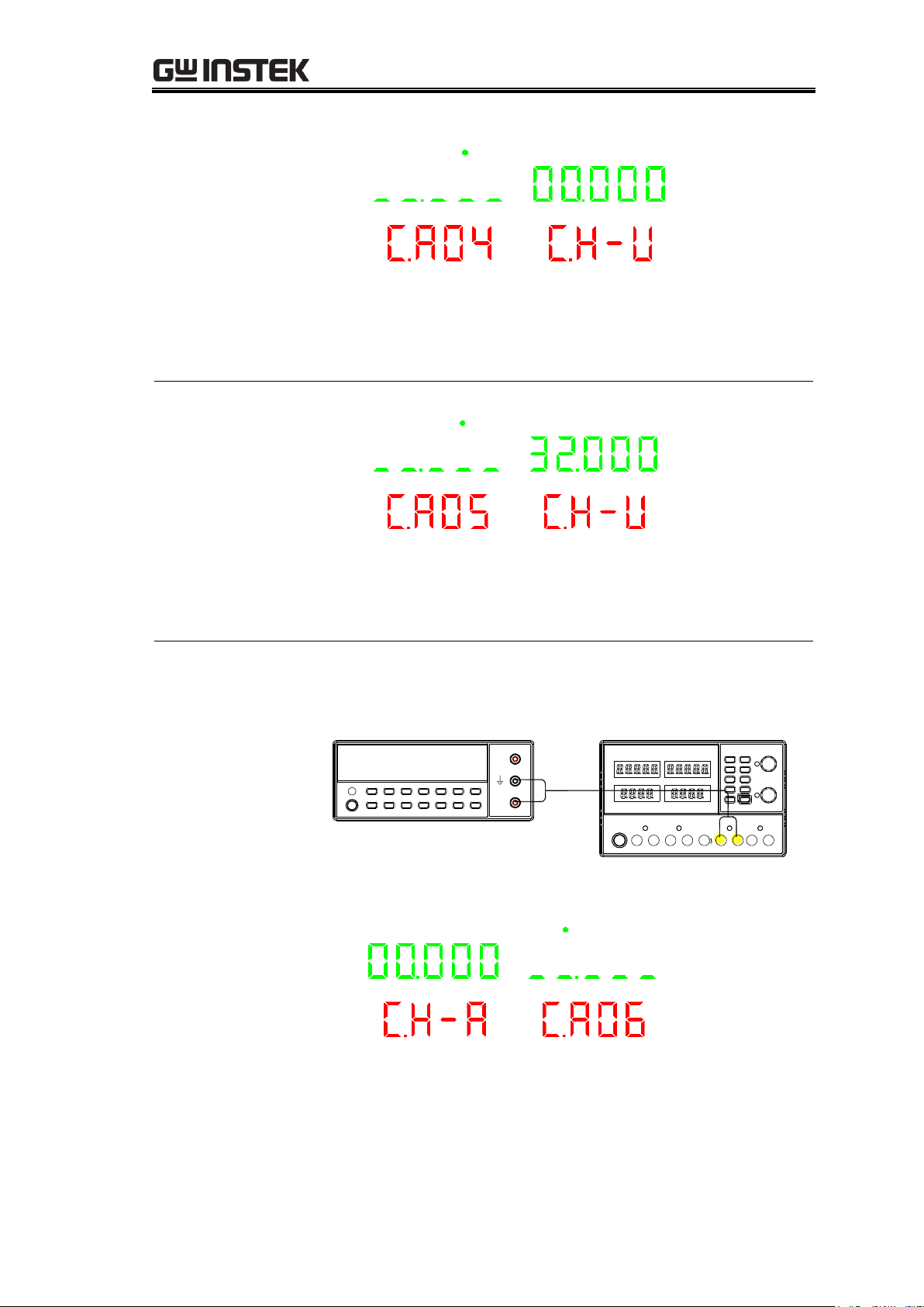
Connect the multimeter cable to the CH2 output terminals.
Connection
Digital Multimeter
V
A
CH2
29
Page 30
GPD-3303 Series Service Manual
CA04:
Calibrating CH2
output voltage (0V)
CH4 CH2 CH1 CH3
1. Read the voltage value on CH2 with the DMM (Unit is
V).
2. Input the reading of the DMM and go to the next step.
CA05:
Calibrating CH2
output voltage
(30V)
CH4 CH2 CH1 CH3
1. Read the voltage value on CH2 with the DMM
(Unit is V).
2. Input the reading of the DMM and enter to next step.
Switching to CH1
output current
calibration
Connect the multimeter cable to the CH1 output terminals.
Connection
Digital Multimeter
V
A
CH1
CA06:
Calibrating CH1
output current (0A)
CH4 CH2 CH1 CH3
1. Read the current value on CH1 with the DMM (Unit is
A).Record 3 digits after decimal point. For example
0.265A.
30
Page 31

Calibration{
2. Input the DMM reading. For example, 0.265A. Enter
digits “2”, “6”and“5”. The the system will
automatically save and go to the next step. (No need to
input the decimal point. The same process is shown
below)
CA07:
Calibrating CH1
output current (3A)
CH4 CH2 CH1 CH3
1. Read the current value on CH1 with the DMM (Unit is
A). For example, 2.965A.
2. Input the DMM reading. Enter digits “2”, “9”,
“6”and“5” and go to the next step.
Switching to CH2
output current
calibration
Connect the multimeter cable to the CH2 output terminals.
Digital Multimeter
V
A
CH2
CA08:
Calibrating CH2
output current (0A)
CH4 CH2 CH1 CH3
1. Read the current value on CH2 with the DMM (Unit is
A).
2. Input the DMM reading and enter the next step.
31
Page 32

GPD-3303 Series Service Manual
CA09:
Calibrating CH2
output current (3A)
CH4 CH2 CH1 CH3
1. Read the current value on CH2 port with the DMM
(Unit is A).
2. Input the DMM reading and go to the next step.
Switching to PARA
output current
calibration
Connect the multimeter cable to the CH1 output terminals.
Connection
Digital Multimeter
V
A
CH1
CA10:
Calibrating PARA
output current
(100mA)
CH4 CH2 CH1 CH3
1. Read the current value on CH1 with the DMM (Unit is
A).
2. Input the DMM reading and go to the next step.
CA11:
Calibrating PARA
output current
(1.5A)
CH4 CH2 CH1 CH3
1. Read the current value on CH1 with the DMM (Unit is
A).
2. Input the DMM reading and go to the next step.
Calibrating the CH1, CH2 output voltage/current is completed
32
Page 33
Calibration{
Accepted range
GPD-x303S
±0.3mV, ±0.5mA
Equipment
Multimeter
Multimeter – Power supply cable
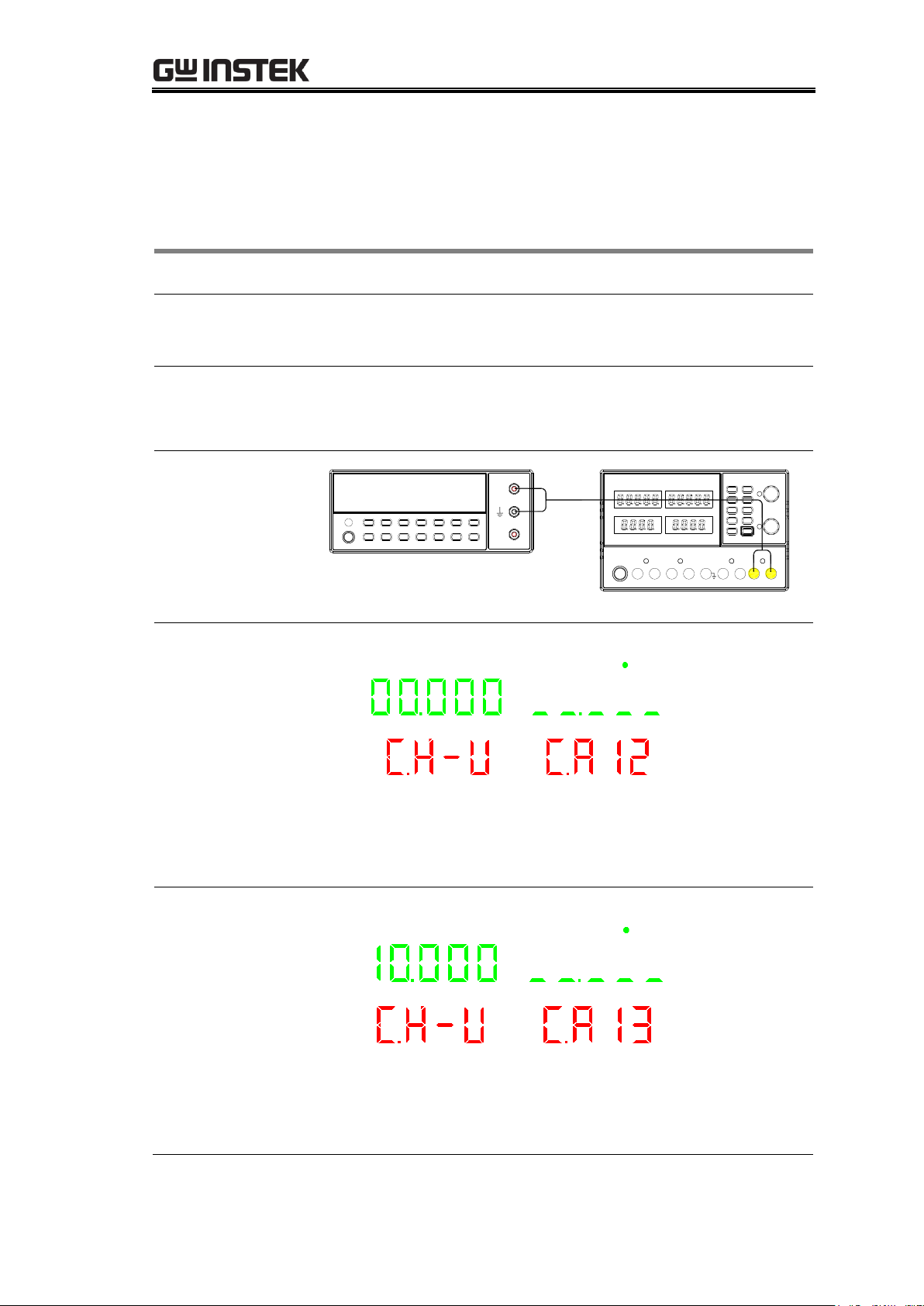
Switching to CH3
output voltage
calibration
Connect the multimeter cable to the CH3 output terminals.
Connection
Digital Multimeter
V
A
CH3
CA12:
Calibrating CH3
output voltage (0V)
CH4 CH2 CH1 CH3
1. Read the voltage value on CH3 with the DMM (Unit is
V).
2. Input the DMM reading and go to the next step.
CA13:
Calibrating CH3
output voltage
(10V)
CH4 CH2 CH1 CH3
1. Read the voltage value on CH3 with the DMM (Unit is
V).
2. Input the DMM reading and go to the next step.
Calibrating CH3/4 Output voltage/Current(4303S)
33
Page 34

GPD-3303 Series Service Manual
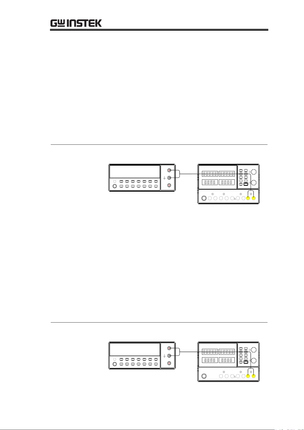
Switching to CH4
output voltage
calibration
Connect the multimeter cable to the CH4 output terminals.
Connection
Digital Multimeter
V
A
CH4
CA14:
Calibrating CH4
output voltage (0V)
CH4 CH2 CH1 CH3
1. Read the voltage value on CH4 with the DMM (Unit is
V).
2. Input the DMM reading and go to the next step.
CA15:
Calibrating CH4
output voltage (5V)
CH4 CH2 CH1 CH3
1. Read the voltage value on CH4 with the DMM (Unit is
V).
2. Input the reading on the DMM and go to the next step.
Switching to CH3
output current
calibration
Connect the multimeter cable to the CH3 output terminals.
Connection
Digital Multimeter
V
A
CH3
34
Page 35

Calibration{
CA016:
Calibrating CH3
output current (0A)
CH4 CH2 CH1 CH3
1. Read the current value on CH3 with the DMM (Unit is
A).
2. Input the reading on the DMM and go to the next step.
CA17:
Calibrating CH3
output current (3A)
CH4 CH2 CH1 CH3
1. Read the current value on CH3 with the DMM (Unit is
A).
2. Input the reading on the DMM and go to the next step.
Switching to CH4
output current
calibration
Connect the multimeter cable to the CH4 output terminals.
Connection
Digital Multimeter
V
A
CH4
CA18:
Calibrating CH4
output current (0A)
CH4 CH2 CH1 CH3
1. Read the current value on CH4 with the DMM (Unit is
A).
2. Input the reading on the DMM and go to the next step.
35
Page 36

GPD-3303 Series Service Manual
CA19:
Calibrating CH4
output current (1A)
CH4 CH2 CH1 CH3
1. Read the current value on CH4 with the DMM (Unit is
A).
2. Input the reading on the DMM and press the
VOLTAGE knob twice to exit the calibration mode.
Calibrating the CH3, CH4 output voltage/current is completed
36
Page 37

Verification{
VERIFICATION
The Verification chapter describes how to make sure the
power supply is operating properly by verifying its major
functionalities. The verification is intended for a full
performance inspection before shipping the power supply
to the end user, after major component replacements, or a
firmware upgrade.
Preparing for Verification ......................................................... 38
Verification Log ....................................................................... 39
Verifying High Voltage Insulation ............................................. 42
Verifying Output Voltage Accuracy ........................................... 43
Verifying Output Current Accuracy ........................................... 46
Verifying CH3 Overload (3303S) ............................................... 48
Verifying Voltage Load Regulation ............................................ 49
Verifying Voltage Line Regulation ............................................. 54
Verifying Current Load Regulation ............................................ 55
Verifying Ripple Voltage .......................................................... 58
37
Page 38

GPD-3303 Series Service Manual
Note
In order to ensure performance accuracy, we recommend
you to verify all items listed in this chapter at once.
When to verify the
specification
When using the power supply in a new environment
After replacing one of the major internal modules, such
as front panel or power supply PCB
After updating the firmware
When you need to make sure that the power supply is
malfunctioning or not
Pre-verification
test
To make verification more effective, the following test is
recommended before the verification.
Burn-in test: 4 hours, 45~47°C, RH 65%
Verification
Environment
Location: Indoor, no direct sunlight, dust free
Relative Humidity: < 80%
Temperature: +20°C~+30°C
Warm-up time: ≥ 30 minutes
Verification
equipments
Hi-pot tester with cable
Digital multimeter with cable
Electronic load with cable
AC power supply with cable
For detailed requirements for the equipments, see page21.
When the
verification fails…
For CH1/CH2 output voltage and current, calibrate the
power supply (page23).
For CH3/CH4 (4303S) output voltage and current,
calibrate the power supply (page33).
For other items, send the power supply back to the
factory for repair.
Preparing for Verification
38
Page 39

Verification{
Model
GPD-2303S
GPD-3303S
GPD-4303S
Serial number
____________________
Date
Year___________
Month__________
Date___________
Verified by
Name____________________________
Company/Contact_________________________
Environment
Temperature______°C
Humidity______%
Item
Location
Result
Pass/Fail
Insulation
resistance
CH1(+) – GND
CH1(-) – GND
CH2(+) - GND
CH2(-) – GND
CH3(+) - GND
CH3(-) – GND
CH4(+) - GND
CH4(-) – GND
AC socket(N) - GND
AC socket(L) – GND
_______Ω
_______Ω
_______Ω
_______Ω
_______Ω
_______Ω
_______Ω
_______Ω
_______Ω
_______Ω
Pass
Pass
Pass
Pass
Pass
Pass
Pass
Pass
Pass
Pass
Fail
Fail
Fail
Fail
Fail
Fail
Fail
Fail
Fail
Fail
Insulation resistance range: > 20MΩ (CH-GND), > 30MΩ (AC-GND)
Item
Location
Result
Pass/Fail
Withstanding
CH1(+) – GND
CH2(+) - GND
CH3(+) - GND
CH4(+) - GND
______mA
______mA
______mA
______mA
Pass
Pass
Pass
Pass
Fail
Fail
Fail
Fail
Withstanding range: 3mA
Item
DMM reading
GPD reading
Delta
Pass/Fail
CH1
CH2
CH3
CH4
__________V
__________V
__________V
__________V
__________V
__________V
__________V
__________V
_______mV
_______mV
_______mV
_______mV
Pass
Pass
Pass
Pass
Fail
Fail
Fail
Fail
Verification Log
Print out these pages and record the results. Keep it with the power supply.
Voltage insulation
Output voltage accuracy
39
Page 40

GPD-3303 Series Service Manual
GPD-x303S :CH1/CH2 Range: 0.03% of rdg + 10mV
GPD-4303S :CH3/CH4 Range: 0.03% of rdg + 10mV
GPD-3303S :CH3 Range: 5% of rdg
Item
DMM reading
GPD reading
Delta
Pass/Fail
CH1
CH2
CH3
CH4
__________A
__________A
__________A
__________A
_________A
_________A
_________A
_________A
_______mA
_______mA
_______mA
_______mA
Pass
Pass
Pass
Pass
Fail
Fail
Fail
Fail
GPD-x303S :CH1/CH2 range: 0.3% of rdg + 10mA
GPD-4303S :CH3/CH4 range: 0.3% of rdg + 10mA
Item
DMM load on
DMM load off
Delta
Pass/Fail
CH1
CH2
CH3
CH4
Tracking series
Tracking parallel
__________V
__________V
__________V
__________V
__________V
__________V
__________V
__________V
__________V
__________V
__________V
__________V
_______mV
_______mV
_______mV
_______mV
_______mV
_______mV
Pass
Pass
Pass
Pass
Pass
Pass
Fail
Fail
Fail
Fail
Fail
Fail
GPD-x303S :CH1/CH2 range:0.01%+3mV
GPD-3303S :CH3 range: 5mV
GPD-4303S :CH3/CH4 range: 0.01%+3mV
Tracking series range: 0.1%+10mV of Master (0~30V)
(No Load, with load add load regulation≤100mV)
Tracking parallel range: 0.01%+3mV
Item
DMM AC–10%
DMM AC+10%
Delta
Pass/Fail
CH1
CH2
CH3
CH4
__________V_
__________V
__________V
__________V
__________V
__________V
__________V
__________V
______mV
______mV
______mV
______mV
Pass
Pass
Pass
Pass
Fail
Fail
Fail
Fail
GPD-x303S :CH1/CH2 range: 0.01% ± 3mV
GPD-3303S :CH3 range: 3mV
GPD-4303S :CH3/CH4 range: 0.01% ± 3mV
Output current accuracy
Voltage load regulation
Voltage line regulation
40
Page 41

Verification{
Item
DMM load on
DMM load off
Delta
Pass/Fail
CH1
CH2
CH3
CH4
__________A
__________A
__________A
__________A
__________A
__________A
_________A
_________A
_______mA
_______mA
_______mA
_______mA
Pass
Pass
Pass
Pass
Fail
Fail
Fail
Fail
Range: 0.2% + 3mA
Item
DMM load on
DMM load off
Delta
Pass/Fail
CH1
CH2
CH3
CH4
Tracking series
Tracking parallel
__________V
__________V
__________V
__________V
__________V
__________V
__________V
__________V
__________V
__________V
__________V
__________V
_______mV
_______mV
_______mV
_______mV
_______mV
_______mV
Pass
Pass
Pass
Pass
Pass
Pass
Fail
Fail
Fail
Fail
Fail
Fail
CH1/CH2/CH3/CH4 range: 1mVrms
Tracking series range: 2mVrms
Tracking parallel range: 1mVrms
Current load regulation
Voltage ripple
41
Page 42

GPD-3303 Series Service Manual
Accepted range
Insulation
20MΩ (Channel output – ground)
30MΩ (AC cord – ground)
Withstanding
3mA (AC 2000V, 10 seconds)
Equipment
Hi-pot tester
Testing cable
Connection
Hi-Pot Tester
Configurations
Power supply: power off (power cord not connected)
Hi-pot tester: Insulation resistance test mode, DC 500V
Verifying insulation
resistance
Apply the insulation resistance test between the following
points and record the result into the log.
CH1 + output → GND terminal
CH1 – output → GND terminal
CH2 + output → GND terminal
CH2 – output → GND terminal
CH3 + output → GND terminal(3303S/4303S)
CH3 – output → GND terminal(3303S/4303S)
CH4 + output → GND terminal(4303S)
CH4 – output → GND terminal(4303S)
AC socket N terminal → AC socket GND terminal
AC socket L terminal → AC socket GND terminal
Verifying
withstanding
1. Power up the power supply.
2. Change the hi-pot tester configuration as follows.
Withstanding test, AC 2000V, 10 seconds
3. Apply the withstanding test between the following
points and record the result into the log.
CH1 + output → GND terminal
CH2 + output → GND terminal
CH3 + output → GND terminal (3303S/4303S)
CH4 + output → GND terminal (4303S)
Verifying the high voltage insulation is completed
Verifying High Voltage Insulation
42
Page 43

Verification{
Accepted range
CH1, CH2
0.03% of rdg + 10mV
CH3
5% of rdg (3303S)
0.03% of rdg + 10mV (4303S)
CH4
0.03% of rdg + 10mV (4303S)
Equipment
Multimeter
Multimeter – Power supply cable
Connection
Digital Multimeter
V
A
CH1
Configurations
Power supply: CH1, 10V/3A output, independent mode
Multimeter: DC voltage mode
Verifying CH1
output voltage
1. Record both the power supply and multimeter voltage
readings into the log.
2. Calculate the difference between the two readings and
record it as the output voltage accuracy (CH1, 10V).
3. Change the power supply output voltage to 30V.
4. Record both the power supply and multimeter voltage
readings into the log.
5. Calculate the difference between the two readings and
record it as the output voltage accuracy (CH1, 30V).
Verifying CH2
output voltage
1. Connect the CH2 output to the multimeter.
Digital Multimeter
V
A
CH2
Verifying Output Voltage Accuracy
43
Page 44
GPD-3303 Series Service Manual
2. Set the output voltage to 10V.
3. Record both the power supply and multimeter voltage
readings into the log.
4. Calculate the difference between the two readings and
record it as the output voltage accuracy (CH2, 10V).
5. Change the power supply output voltage to 30V.
6. Record both the power supply and multimeter voltage
readings into the log.
7. Calculate the difference between the two readings and
record it as the output voltage accuracy (CH2, 30V).
Verifying CH3
output voltage
(4303S)
1. Connect the CH3 output to the multimeter.
Digital Multimeter
V
A
CH3
2. Set the output voltage to 5V.
3. Record both the power supply and multimeter voltage
readings into the log.
4. Calculate the difference between the two readings and
record it as the output voltage accuracy (CH3, 5V).
5. Change the power supply output voltage to 10V.
6. Record both the power supply and multimeter voltage
readings into the log.
7. Calculate the difference between the two readings and
record it as the output voltage accuracy (CH3, 10V).
Verifying CH3
output voltage
(3303S)
1. Connect the CH3 output to the multimeter.
Digital Multimeter
V
A
CH3
44
Page 45

Verification{
2. Select 2.5V as the CH3 output voltage.
3. Record both the power supply and multimeter voltage
readings into the log.
4. Calculate the difference between the two readings and
record it as the output voltage accuracy (CH3, 2.5V).
5. Select 3.3V as the CH3 output voltage and repeat
measuring the output voltage accuracy.
6. Select 5V as the CH3 output voltage and repeat
measuring the output voltage accuracy.
Verifying CH4
output voltage
(4303S)
1. Connect the CH4 output to the multimeter.
Digital Multimeter
V
A
CH4
2. Select 2.5V as the CH4 output voltage.
3. Record both the power supply and multimeter voltage
readings into the log.
4. Calculate the difference between the two readings and
record it as the output voltage accuracy (CH4, 2.5V).
5. Select 5V as the CH4 output voltage and repeat
measuring the output voltage accuracy.
Verifying the output voltage accuracy is completed
45
Page 46

GPD-3303 Series Service Manual
Accepted range
CH1, CH2
0.3% of reading + 10mA
CH3, CH4
0.03% of reading + 10mV (4303S)
Equipment
Multimeter
Multimeter – Power supply cable
Connection
1. Connect the CH1 output to the multimeter.
Digital Multimeter
V
A
CH1
Configurations
Power supply: CH1, 30V/3A output, independent mode
Multimeter: DC current mode
Verifying CH1
output current
2. Record both the power supply and multimeter current
readings into the log.
3. Calculate the difference between the two readings and
record it as the output current accuracy (CH1).
Connection
1. Connect the CH2 output to the multimeter.
Digital Multimeter
V
A
CH2
Configurations
Power supply: CH2, 30V/3A output, independent mode
Multimeter: DC current mode
Verifying CH2
output current
2. Record both the power supply and multimeter current
readings into the log.
3. Calculate the difference between the two readings and
record it as the output current accuracy (CH2).
Verifying Output Current Accuracy
46
Page 47

Verification{
Connection
1. Connect the CH3 output to the multimeter.
Digital Multimeter
V
A
CH3
Configurations
Power supply: CH3, 5V/3A output, independent mode
Multimeter: DC current mode
Verifying CH3
output current
(4303S)
2. Record both the power supply and multimeter current
readings into the log.
3. Calculate the difference between the two readings and
record it as the output current accuracy (CH3).
Connection
1. Connect the CH4 output to the multimeter.
Digital Multimeter
V
A
CH4
Configurations
Power supply: CH4, 5V/1A output, independent mode
Multimeter: DC current mode
Verifying CH4
output current
(4303S)
2. Record both the power supply and multimeter current
readings into the log.
3. Calculate the difference between the two readings and
record it as the output current accuracy (CH4).
Verifying the output current accuracy is completed
47
Page 48

GPD-3303 Series Service Manual
Accepted range
Overload threshold
3.25±0.2A
Equipment
Multimeter
Multimeter – Power supply cable
Electronic load
Electronic load – Power supply cable
Connection
Digital Multimeter
V
A
Electronic Load
CH3 - CH3 +
+ -
Configurations
Power supply: CH3, 5V output
Multimeter: DC current mode
Verifying CH3
overload indicator
threshold
1. Adjust the amount of load and record the multimeter
reading when the CH3 overload indicator turns on.
2. Record the multimeter current readings into the log.
3. Record it as the output overload threshold (CH3).
Verifying the CH3(3303S) overload is completed
Verifying CH3 Overload (3303S)
48
Page 49

Verification{
Accepted range
CH1, CH2
independent
0.01% + 3mV
CH3
(3303S): 5mV
(4303S): 0.01% + 3mV
CH4
0.01% + 3mV
Tracking series
100mV
Tracking parallel
0.01% + 3mV
Equipment
Multimeter
Multimeter – Power supply cable
Electronic load
Electronic load – Power supply cable
Connection
Digital Multimeter
V
A
CH1
Electronic Load
+ -
Configurations
Power supply: CH1, 30V/3.2A output, independent
mode
Multimeter: DC voltage mode
Electronic load: 30V, 3A, load on
Verifying CH1
voltage load
regulation
1. Record the multimeter voltage reading into the log.
2. Turn off the electronic load.
3. Record the multimeter voltage reading into the log.
Verifying Voltage Load Regulation
49
Page 50

GPD-3303 Series Service Manual
4. Calculate the difference between the two readings and
record it as the voltage load regulation (CH1, 3A).
Verifying CH2
voltage load
regulation
1. Connect the CH2 output to the multimeter and load.
Digital Multimeter
V
A
Electronic Load
+ -
CH2
2. Change the configuration as follows.
Power supply output current: 30V/3.2A
Electronic load settings: 30V, 3A, load on
3. Record the multimeter voltage reading into the log.
4. Turn off the electronic load.
5. Record the multimeter voltage reading into the log.
6. Calculate the difference between the two readings and
record it as the voltage load regulation (CH2, 3A).
Verifying CH3
voltage load
regulation
1. Connect the CH3 output to the multimeter and load.
Digital Multimeter
V
A
Electronic Load
+ -
CH3
50
Page 51

Verification{
2. Change the configuration as follows.
Power supply output voltage: 5V/3.2A
Electronic load settings: 5V, 3A, load on
3. Record the multimeter voltage reading into the log.
4. Turn off the electronic load.
5. Record the multimeter voltage reading into the log.
6. Calculate the difference between the two readings and
record it as the voltage load regulation (CH3).
Verifying CH4
voltage load
regulation
1. Connect the CH4 output to the multimeter and load.
Digital Multimeter
V
A
Electronic Load
+ -
CH4
2. Change the configuration as follows.
Power supply output voltage: 5V/1.2A
Electronic load settings: 5V, 1A, load on
3. Record the multimeter voltage reading into the log.
4. Turn off the electronic load.
5. Record the multimeter voltage reading into the log.
6. Calculate the difference between the two readings and
record it as the voltage load regulation (CH4).
Verifying Tracking
series load
regulation
1. Connect the power supply output to the multimeter
and load in the tracking series mode:
CH1 + terminal → Electronic load + terminal
CH2 – terminal → Electronic load – terminal
51
Page 52

GPD-3303 Series Service Manual
Digital Multimeter
V
A
CH1 +
Electronic Load
+ -
CH2 -
2. Change the configuration as follows.
Power supply settings: Tracking series, 60V, 3.2A
Electronic load settings: 60V, 3A, load on
3. Record the multimeter voltage reading into the log.
4. Turn off the electronic load.
5. Record the multimeter voltage reading into the log.
6. Calculate the difference between the two readings and
record it as the voltage load regulation (tracking series).
Verifying Tracking
parallel load
regulation
1. Connect the power supply output to the multimeter
and load in the tracking series mode:
CH1 + terminal → Electronic load + terminal
CH1 – terminal → Electronic load – terminal
Digital Multimeter
V
A
CH1 -
Electronic Load
+ -
CH1 +
52
Page 53

Verification{
2. Change the configuration as follows.
Power supply settings: Tracking parallel, 30V, 6.4A
Electronic load settings: 30V, 6A, load on
3. Record the multimeter voltage reading into the log.
4. Turn off the electronic load.
5. Record the multimeter voltage reading into the log.
6. Calculate the difference between the two readings and
record it as the voltage load regulation (tracking
parallel).
Verifying the voltage load regulation is completed
53
Page 54

GPD-3303 Series Service Manual
Accepted range
CH1, CH2, CH3, CH4)
0.01% + 3mV
Equipment
Multimeter
Multimeter – Power supply cable
Electronic load
Electronic load – Power supply cable
AC power supply
Connection
Digital Multimeter
V
A
Electronic Load
+ -
AC Power Supply
Configurations
Power supply: CH1, 30V/3.2A output, independent
mode
Multimeter: DC voltage mode
Electronic load: 30V, 3A, load on
AC power supply: rating voltage – 10%
Verifying CH1
voltage line
regulation
1. Record the multimeter voltage reading into the log.
2. Increase the AC power supply voltage to (rating
voltage + 10% or -10%).
220V rating example: 198V →220V→ 242V
3. Record the multimeter voltage reading into the log.
4. Calculate the difference between the two readings and
record it as the voltage line regulation (CH1, 3A).
Verifying other
channels voltage
line regulation
Connection method and setting for other channels are
similar to CH1.
Verifying the voltage line regulation is completed
Verifying Voltage Line Regulation
54
Page 55

Verification{
Accepted range
CH1, CH2,
CH3, CH4(4303S)
0.2% + 3mA
Equipment
Multimeter
Multimeter – Power supply cable
Electronic load
Electronic load – Power supply cable
Connection
Digital Multimeter
V
A
Electronic Load
CH1 - CH1 +
+ -
Configurations
Power supply: CH1, 30V/3A output, independent mode
Multimeter: DC current mode
Electronic load: 30V, 3A, load on
Verifying CH1
current load
regulation
1. Record the multimeter current reading into the log,
when the CH1 CC light turns on.
2. Decrease the electronic load level to CH1 CV light turns
on.
3. Record the multimeter current reading into the log.
4. Calculate the difference between the two readings and
record it as the current load regulation (CH1).
Verifying Current Load Regulation
(Continues to the next page)
55
Page 56

GPD-3303 Series Service Manual
Connection
1. Connect the CH2 output to the multimeter and load.
Digital Multimeter
V
A
Electronic Load
CH2 - CH2 +
+ -
Configurations
Power supply: CH2, 30V/3A output, independent mode
Multimeter: DC current mode
Electronic load: 30V, 3A, load on
Verifying CH2
current load
regulation
2. Record the multimeter current reading into the log,
when the CH2 CC light turns on.
3. Decrease the electronic load level to CH2 CV light turns
on.
4. Record the multimeter current reading into the log.
5. Calculate the difference between the two readings and
record it as the current load regulation (CH2).
Connection
1. Connect the CH3 output to the multimeter and load.
Digital Multimeter
V
A
Electronic Load
CH3 - CH3 +
+ -
56
Page 57
Verification{
Configurations
Power supply: CH3, 5V/3A output, independent mode
Multimeter: DC current mode
Electronic load: 30V, 3A, load on
Verifying CH3
current load
regulation
(4303S)
2. Record the multimeter current reading into the log,
when the CH3 CC light turns on.
3. Decrease the electronic load level to CH3 CV light turns
on.
4. Record the multimeter current reading into the log.
5. Calculate the difference between the two readings and
record it as the current load regulation (CH3).
Connection
1. Connect the CH4 output to the multimeter and load.
Digital Multimeter
V
A
Electronic Load
CH4 - CH4 +
+ -
Configurations
Power supply: CH4, 5V/1A output, independent mode
Multimeter: DC current mode
Electronic load: 30V, 1A, load on
Verifying CH4
current load
regulation
(4303S)
2. Record the multimeter current reading into the log,
when the CH4 CC light turns on.
3. Decrease the electronic load level to CH4 CV light turns
on.
4. Record the multimeter current reading into the log.
5. Calculate the difference between the two readings and
record it as the current load regulation (CH4).
Verifying the current load regulation is completed
57
Page 58

GPD-3303 Series Service Manual
Accepted range
CH1, CH2, CH3, CH4
independent
1mVrms
Tracking series
2mVrms
Tracking parallel
1mVrms
Equipment
AC millivolt meter
AC millivolt meter – Power supply cable
Electronic load
Electronic load – Power supply cable
Connection
CH1
Electronic Load
+ -
AC Millivolt
Meter
Configurations
Power supply: CH1/CH2, 30V/3.2A output, independent
mode
Multimeter: DC voltage mode
Electronic load: 30V, 3A, load on
Verifying CH1
ripple voltage
1. Record the millivolt meter voltage reading into the log
as the ripple voltage (CH1).
Verifying CH2
ripple voltage
2. Connect the CH2 output to the millivolt meter and
load.
Verifying Ripple Voltage
(Continues to the next page)
58
Page 59

Verification{
CH2
Electronic Load
+ -
AC Millivolt
Meter
3. Record the millivolt meter voltage reading into the log
as the ripple voltage (CH2).
Verifying CH3
ripple voltage
1. Connect the CH3 output to the millivolt meter and
load.
CH3
Electronic Load
+ -
AC Millivolt
Meter
2. Change the configuration as follows.
Power supply output voltage: 5V/3.2A
Electronic load settings: 5V, 3A, load on
3. Record the millivolt meter voltage reading into the log
as the ripple voltage (CH3).
59
Page 60

GPD-3303 Series Service Manual
Verifying CH4
ripple voltage
1. Connect the CH4 output to the millivolt meter and
load.
CH3
Electronic Load
+ -
AC Millivolt
Meter
2. Change the configuration as follows.
Power supply output voltage: 5V/1.2A
Electronic load settings: 5V, 1A, load on
3. Record the millivolt meter voltage reading into the log
as the ripple voltage (CH4).
Verifying Tracking
series ripple
voltage
1. Connect the power supply output to the millivolt meter
and load in the tracking series mode:
CH1 + terminal → Electronic load + terminal
CH2 – terminal → Electronic load – terminal
Electronic Load
+ -
AC Millivolt
Meter
CH1 +CH2 -
60
Page 61

Verification{
2. Change the configuration as follows.
Power supply settings: Tracking series, 60V, 3.2A
Electronic load settings: 60V, 3A, load on
3. Record the millivolt meter voltage reading into the log
as the ripple voltage (tracking series).
Verifying Tracking
parallel ripple
voltage
1. Connect the power supply output to the multimeter
and load in the tracking series mode:
CH1 + terminal → Electronic load + terminal
CH1 – terminal → Electronic load – terminal
CH1
Electronic Load
+ -
AC Millivolt
Meter
2. Change the configuration as follows.
Power supply settings: Tracking parallel, 30V, 6.4A
Electronic load settings: 30V, 6A, load on
3. Record the millivolt meter voltage reading into the log
as the ripple voltage (tracking parallel).
Verifying the ripple voltage is completed
61
Page 62

GPD-3303 Series Service Manual
When to update
the firmware
You might need to update the firmware in the following
cases.
The GPD-x303S system malfunction
Firmware update request from GW Instek or customers
Tools for updating
the firmware
Firmware file (provided from GW Instek)
Password for entering the firmware update mode
(provided from GW Instek)
GPD-x303S USB driver (details in page63)
Terminal application (Hyperterminal or similar software)
Windows 2000 or XP based PC
USB cable, TypeA (host, PC) to Type B (slave, GPD)
Updating
procedures
(details follow)
1. Installing the USB driver to the PC
2. Configuring the interface
3. Updating the firmware
If you have already installed the USB driver, go directly to
step 2 (page64).
If you have already installed the USB driver and configured
the interface, go directly to step 3 (page66).
UPDATING THE FIRMWARE
The Firmware update chapter describes how to overwrite
(update) the GPD-x303S firmware via the USB interface. For
GPD-x303S, send the power supply back to GW Instek in
case you need to update its firmware.
Preparing for Firmware Update ................................................. 62
Installing the USB Driver to the PC............................................ 63
Installing the bootloader software to the PC ............................ 64
Updating the Firmware ............................................................. 67
Preparing for Firmware Update
62
Page 63

Updating the Firmware{
Downloading the
USB driver
Access the following website and download the USB driver
for FT232R, the USB device chip used in the GPD.
http://www.ftdichip.com/Drivers/VCP.htm
Installing the
driver
1. Power up the GPD-x303S and the PC.
2. Connect the GPD-x303S and the PC using the USB cable.
A dialog window appears, requesting the driver file.
3. Point to the downloaded driver and install it.
Verifying the
installation
1. Open the Device Manager in the Control Panel.
2. Select the Hardware tab and open the System properties.
3. The USB driver should be recognized as one of the COM
ports.
Installing the USB driver is completed. Move on to the next step,
Configuring
the Interface
.
Installing the USB Driver to the PC
If the USB driver has already been installed, skip this section and go to the
Configuring the Interface section, page64.
63
Page 64

GPD-3303 Series Service Manual
Downloading
the bootloader
software
The AN1310 high-speed serial bootloader software package
(including full source code) can be downloaded from the
following website.
http:// www.microchip.com/applicationnotes.
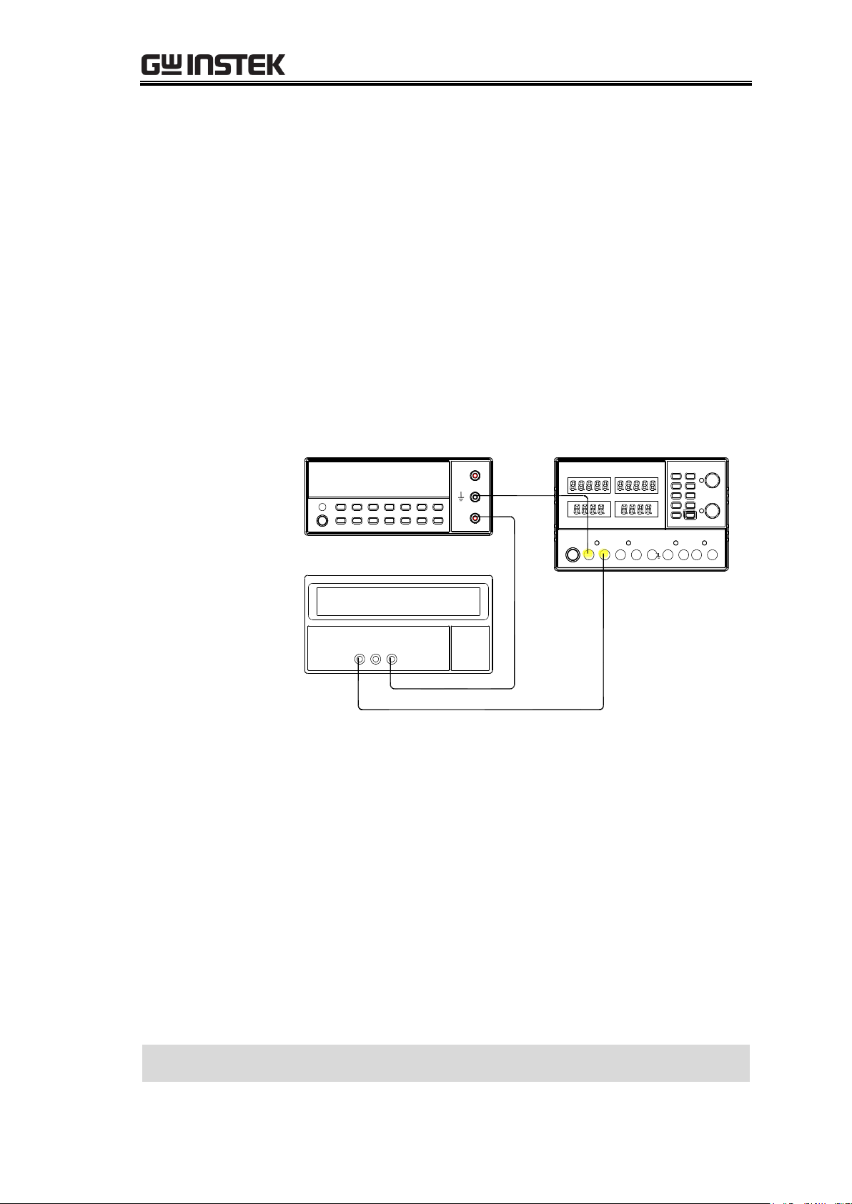
1. Enter the Microchip website. In the search bar, type
AN1310. The AN1310 documentation and source code
should appear. Select AN1310 Source Code.
2. Select the link showed in red below.
Installing the bootloader software to the PC
If the bootloader software has already been installed, skip this section and go to the
Configuring the Interface section, page64.
64
Page 65
Updating the Firmware{
3. You will be shown page shown below.
4. Click on the download icon, shown in red above.
Installation
Unzip the download package and install.
Verifying the
installation
You can confirm the installation by looking in the Start menu,
as shown below.
Set Parameters
1. Click on the Serial Bootloader AN1310 icon, as shown
above. The following screen appears.
2. If this is the first time you have used the bootloader
program, the serial port settings and baud rate must first be
configured.
65
Page 66

GPD-3303 Series Service Manual
3. Clicking ProgramSettings will make the following screen
appear.
4. Select the COM port number and the Bootload Baud Rate,
and then click OK.
Installing the bootloader software is completed. Move on to the next step,
Updating the firmware
.
66
Page 67

Updating the Firmware{
Steps
1. Power up the GPD-x303S.
2. Connect the GPD-x303S to the PC using the USB cable.
3. Below shows the AN1310 bootloader program toolbar.
4. Click the Break/Reset Mode button or press F3 until
“Break asserted” appears.
5. Turn on the GPD-x303s.
6. To enter the bootstrap mode, click the red “Bootloader
Mode” button or press the F4 key. If communication is
established, the PC will display the firmware version of
the bootstap program and the PIC device information.
This is shown below.
Selecting the
firmware file
7. Load the HEX update file.
Updating the Firmware
67
Page 68

GPD-3303 Series Service Manual
Updating the
firmware
8. After the file is loaded, click the icon
with the red arrow pointing down or
press the F6 button.
9. Click the green “Run Mode” icon or press the F2 key to
run the software on the GPD-x303S.
10. The GPD will shut down after completion. Remove the
USB cable.
Updating the firmware is completed.
68
Page 69

Replacing the Fuse{
WARNING
Make sure the cause of fuse blowout is fixed before
replacing the fuse.
Rating
100V/120V:T6.3A/250V
220V/230V:T3.15A/250V
Procedures
1. Take off the power cord and remove the fuse socket
using a minus driver.
2. Replace the fuse in the holder.
Replacing the primary fuse is completed
REPLACING THE FUSE
Two types of fuse are inserted in the power supply. The
primary fuse, located in the power cord socket, and the
secondary fuses, mounted on the power supply PCB.
Replacing the Primary Fuse ...................................................... 69
Replacing the Secondary Fuses ................................................. 70
Replacing the Primary Fuse
69
Page 70

GPD-3303 Series Service Manual
WARNING
Make sure the cause of fuse blowout is fixed before replacing
the fuse.
Procedures
1. Take off the outer casing and the supporting bar. For details,
see page72.
2. Locate the secondary fuses on the power supply PCB and
replace the blown fuse.
Rating
Power supply PCB(Yellow area):
F101/F401:T6.3A/250V
F102/F103/F402/F403:T315mA/250V
F701: T6.3A/250V (3303S,4303S)
Rating
Control PCB(Yellow area):
F301: T2A/250V
F702: T315mA/250V (3303S,4303S)
F802: T315mA/250V (4303S)
Replacing the Secondary Fuses
70
Page 71
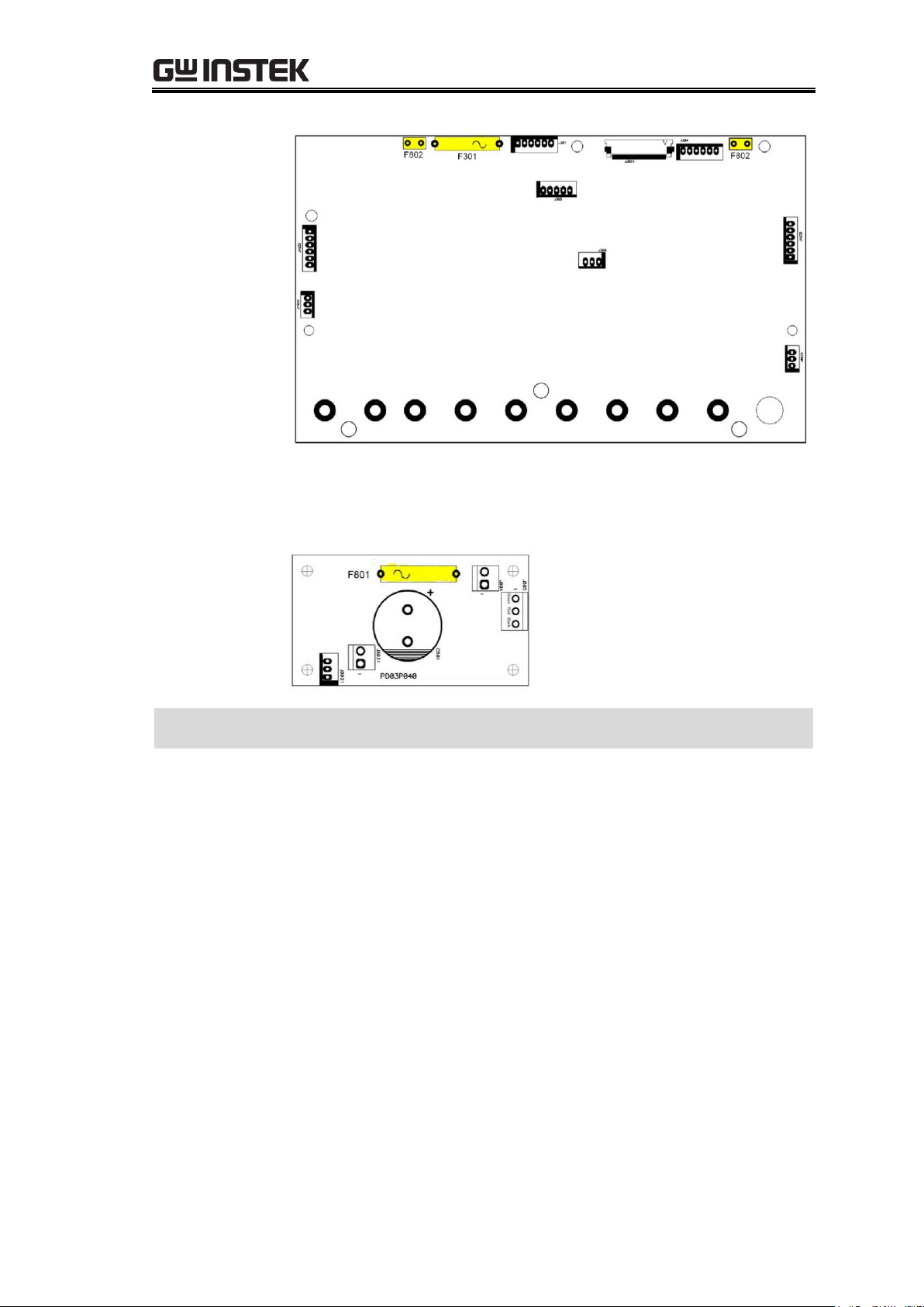
Replacing the Fuse{
Rating
CH4 Power PCB(Yellow area):
F801: T2A/250V (4303S)
Replacing the secondary fuses is completed
71
Page 72

GPD-3303 Series Service Manual
1. Take off two screws from the top handle and six screws from the side panels
and remove it from the outer casing.
DISASSEMBLING THE
POWER SUPPLY
The Disassembly chapter shows how to remove the major
units, PCBs, panels, and outer casing, from the power
supply. The procedures described in this chapter are
intended for parts replacement and board adjustment. The
Parts List chapter (page90) shows more details about the
mechanical structures of the power supply and thus can be
used as a reference.
Outer Casing & Supporting Bar ................................................. 72
Front Panel ............................................................................. 74
Power Supply PCB .................................................................... 76
Outer Casing & Supporting Bar
72
Page 73

Disassembling the Power Supply{
2. Slide the outer casing backward and remove it.
3. Take off four screws from the supporting bar and remove it.
Disassembling the outer casing and supporting bar is completed
73
Page 74

GPD-3303 Series Service Manual
1. Take off the outer casing and supporting bar. For details, see page72.
2. Disconnect the cables from the front panel.
Control PCB:J301, GND Cable(Yellow area)
3. Disconnect the rest of the cables.
a, Power PCB:J1031, J1041, J1061, J4031, J4041, J7021, J7031(Yellow area).
Front Panel
74
Page 75

Disassembling the Power Supply{
b, USB PCB:J901(Yellow area).
c, CH4 power PCB:J8021, J8031(Yellow area).
4. Take off two screws from the bottom of the front panel and pull the front
panel out.
Front panel disassembly is completed
75
Page 76
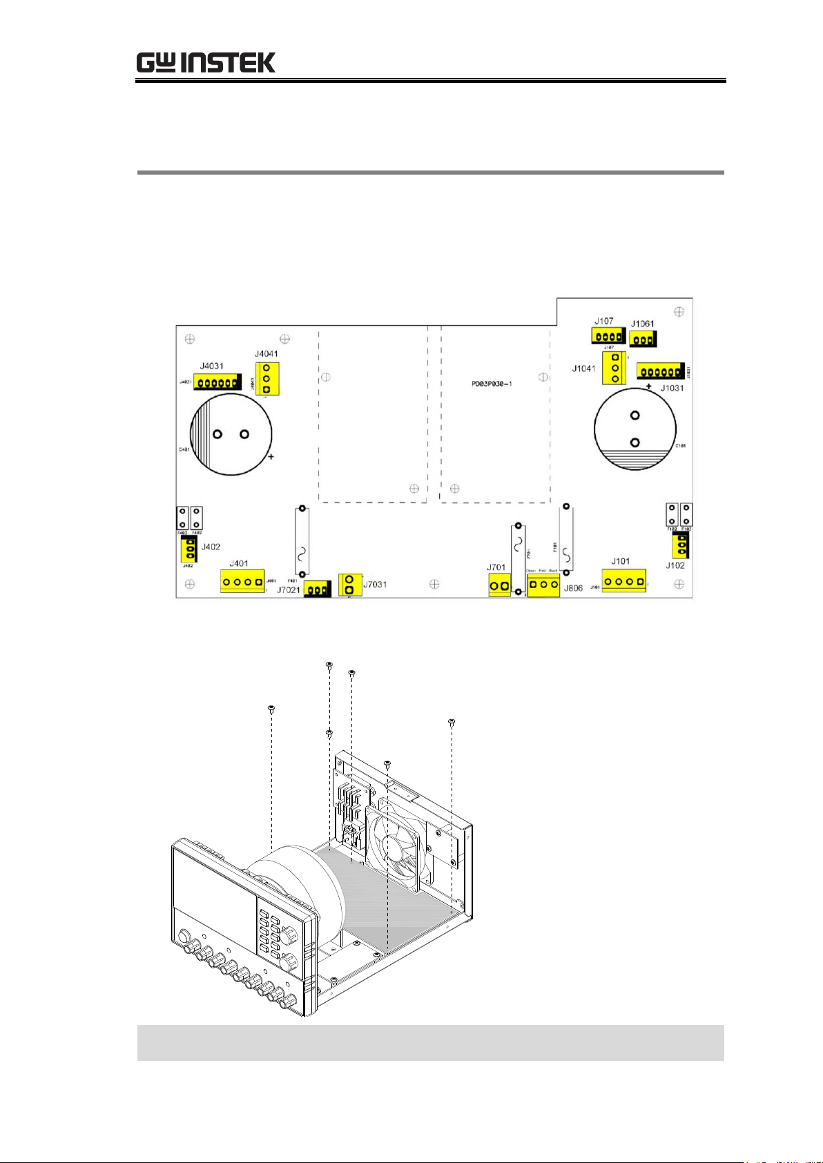
GPD-3303 Series Service Manual
1. Take off the outer casing and supporting bar. For details, see page72.
2. Disconnect all the cables connected to the power supply PCB: J101, J102,
J1031, J1041, J1061, J107, J401, J402, J4031, J4041, J701, J7021, J7031, J806.
(Yellow area)
3. Take off six screws from the power supply PCB and remove it.
Disassembling the power supply PCB is completed
Power Supply PCB
76
Page 77

GPD-x303S PCB & Circuit Diagram{
GPD-X303S PCB & CIRCUIT DIAGRAM
This chapter shows the PCB layout and circuit diagrams
used in the GPD-x303S. For the list of parts including both
the mechanical and PCB parts, see the Parts List chapter,
page90.
Overview ................................................................................ 78
GPD-x303S Control PCB ........................................................... 79
GPD-x303S control PCB layout top side layout......................... 79
GPD-x303S control PCB layout bottom side layout .................. 80
GPD-x303S control PCB circuit diagram 1/4 ............................ 81
GPD-x303S control PCB circuit diagram 2/4 ............................ 82
GPD-x303S control PCB circuit diagram 3/4 ............................ 83
GPD-x303S control PCB circuit diagram 4/4 ............................ 84
GPD-x303S Display PCB ........................................................... 85
GPD-x303S display PCB Top side layout .................................. 85
GPD-x303S display PCB circuit diagram ................................... 86
GPD-x303S Power Supply PCB .................................................. 87
GPD-x303S power supply PCB layout (CH1/CH2/CH3) ............. 87
GPD-x303S power supply PCB circuit diagram
(CH1/CH2/CH3/CH4) ............................................................... 88
GPD-x303S Power Switch PCB, CH4 Power PCB, AC Selector PCB, USB
Interface PCB .......................................................................... 89
77
Page 78

GPD-3303 Series Service Manual
Overview
78
Page 79

GPD-x303S Control PCB
GPD-x303S control PCB layout top side layout
79
Page 80

GPD-3303 Series Service Manual
GPD-x303S control PCB layout bottom side layout
80
Page 81

GPD-x303S control PCB circuit diagram 1/4
81
Page 82

GPD-3303 Series Service Manual
GPD-x303S control PCB circuit diagram 2/4
82
Page 83

GPD-x303S control PCB circuit diagram 3/4
83
Page 84

GPD-3303 Series Service Manual
GPD-x303S control PCB circuit diagram 4/4
84
Page 85

GPD-x303S Display PCB
GPD-x303S display PCB Top side layout
85
Page 86

GPD-3303 Series Service Manual
GPD-x303S display PCB circuit diagram
86
Page 87

GPD-x303S Power Supply PCB
GPD-x303S power supply PCB layout (CH1/CH2/CH3)
87
Page 88

GPD-3303 Series Service Manual
GPD-x303S power supply PCB circuit diagram (CH1/CH2/CH3/CH4)
88
Page 89

GPD-x303S Power Switch PCB, CH4 Power PCB, AC Selector PCB, USB Interface PCB
Power switch PCB layout
Power switch PCB circuit diagram
F80 1
3.15 A/A C250 V
C80 1
0.01 U/250 V
C80 3
0. 22U/275 V
C80 4
4700 PK
C80 5
4700 PK
AC250 V
AC250 V
S80 1
6
TO S802
1
2
3
J80 1
C80 2
0.01 U/250 V
3
1 2
J801 1
CH4 Power PCB layout
CH4 Power PCB circuit diagram
AC selector PCB top side layout
AC selector PCB bottom side layout
AC selector PCB circuit diagram
240V
120V
100V
S80 2
5
S80 3
4
2
1
3
J80 2
4
2
1
3
J80 3
220V
FROM J8011
USB interface PCB layout
USB interface PCB circuit diagram
89
Page 90

GPD-3303 Series Service Manual
PARTS LIST
The Mechanical Parts List chapter shows the diagrams for
all replaceable mechanical components used in the power
supply, together with their descriptions and part numbers.
Use this chapter as a detailed reference for disassembling
the power supplies, or for searching for the part number of
components that require replacing.
Outer Casing ........................................................................... 91
Internal Structures .................................................................. 93
Front Panel ............................................................................. 94
PCB Mount Parts: GPD-2303S ................................................... 95
PCB Mount Parts: GPD-3303S ................................................. 100
PCB Mount Parts: GPD-4303S ................................................. 107
90
Page 91

Parts List
No.1
SCREW OMS, +, 3*6*0.5P, ISO, N
Part No.: 598B-03006NJ
Quantity: 10
No.2
*CA GPD-3303/S HOLDER,ROHS
Part No.: 62PD-333HP101
Quantity: 1
No.3
*CA GPD-3303/S TOP COVER,
ROHS
Part No.: 62PD-333UP1A1
Quantity: 1
No.4
BELT SG120RB1-0(220*20*5),
GRAY+SG120CH1-0(*2)
Part No.: 552G-2202050
Quantity: 1
No.5
*CA PC3030CH1-0, BELT
FASTENER GRAY, ROHS
Part No.: 62PC-303CH301
Quantity: 2
No.6
SCREW FMS, +, 4*10, ISO, N
Part No.: 593B-04010NJ
Quantity: 2
Outer Casing
91
Page 92

Page 93

No
Description
Qty
Part code
1
KNOB ST01M280, 13@, COOL
GRAY 2u, POWER
1
5004-130G010
2
PC 815-CR-1B, JOINT STICK
FOR KNOB
1
63CR-AB1001B
3
PC OS611LK1-C, JOINT STICK
(MIDDLE)
1
63LK-AB1003C
4
PC OS610CR1-0, JOINT STICK
FOR SW, BLACK
1
63LK-AB10020
5
PCB ASS'Y PD03P030
,GPD-4303S (POWER)
1
13PD-433S030
6
SCREW TRUSS, +, 3*6*0.5P, B
TYPE, N
13
591B-03006NB
7
TS GPD-4303S-PT WITH WIRE
C. CM-E-M-597Z ,RoHS
1
3003-PD003001
8
* FAN MGA8024MR-025,
DL24V, 80*80*25, MS, P, CE
1
3812-4620020
9
PCB ASS'Y PD01P100
,GPD-3303D (AC-SW)
1
13PD-333D100
10
* CA GPD-3303/S REAR PLATE,
ROHS
1
62PD-333RP5A1
11
SCREW TMS, +, 3*6, TS-3, N
4
591H-03006NS
12
SCREW FMS, +, 5*8, TS-3, N
4
593H-05008NS
13
* PS R-3013, 6A, 250V, 3P, AC
RECEPTACLE, ROHS
1
3610-00600801
14
SCREW BMS, +, 3*6*0.5P, ISO, N
5
594B-W3006NJ
15
PCB ASS'Y PD03P020
,GPD-4303S (DISPLAY)
1
13PD-433S020
16
* RUBBER FOOT, BLACK(GWS)
4
57FC-30B0130
17
PCB ASS'Y PD03P030
,GPD-4303S (POWER)
1
13PD-433S030
18
SCREW BMS, +, 5*10, ISO, N
4
594B-W5010NJ
19
PCB ASS'Y PD03P040
,GPD-4303S (CH4)
1
13PD-433S040
20
KNOB DS01M19B, 18@, GRAY
DIC650
2
5005-180G01B
Internal Structures
93
Page 94

GPD-3303 Series Service Manual
No
Description
Qty
Part code
1
* BINDING POST, 1P, 5(GREEN), ROHS
1
44BJ-51100401
2
* BINDING POST, 1P, 2(RED), ROHS
3
44BJ-21101001
3
* BINDING POST, 1P, 0(BLACK), ROHS
3
44BJ-01101001
4
* LED CAP EDN-3C-PCW,
3.45@10.1m/m, PINGWOOD, ROHS
5
5323-01003501
5
NP GPD-4303S (台規) MAIN NP ,RoHS
NP GPD-3303S (台規) MAIN NP ,RoHS
NP GPD-2303S (台規) MAIN NP ,RoHS
1
1
1
51PD-4303S201
(4303S)
51PD-3303S201
(3303S)
51PD-2303S201
(2303S)
6
NP GPD-4303S MODEL NP ,RoHS
NP GPD-3303S MODEL NP (新 LOGO)
,RoHS
NP GPD-2303S MODEL NP ,RoHS
1
1
1
51PD-4303S101
(4303S)
51PD-3303S1B1
(3303S)
51PD-2303S101
(2303S)
7
PC GPD-X303/S/D PLASTIC FRONT
PLATE ,RoHS
1
63FP-AG1062B1
8
PCB ASS'Y PD03P020 ,GPD-4303S
(DISPLAY)
1
13PD-433S020
9
SCREW TMS, +, 3*6, TS-3, N
6
591H-03006NS
10
PCB ASS'Y PD03P010 ,GPD-X303S
1
13PD-X33S010
11
SCREW TMS, 3*8, TS-3, N
5
591H-03008NS
12
NUT HEXAGON, +, M3*0.5P, ISO, N
7
6001-CN0030J
13
SILICON RUBBER GPD-X303S ,RoHS
SILICON RUBBER GPD-3303 ,10 KEYS
,RoHS
1
1
57RB-40G08501
(4303S)
57RB-40G051A1
(2303S/3303S)
14
* SPACER SUPPORT SCT-14,
H=14mm, ROHS
3
5321-00414001
Front Panel
94
Page 95

BD BD101,BD401,
* BRIDGE GBU402 ,RoHS ,4A ,200V ,HY
BD301,
BRIDGE 2W06GL-5300E4 ,2A ,600Vmax ,VISHAT ,RoHS
BZ BZ502,
* BUZZER 6V ,DC ,12@*9(H) ,P ,OBO-1206A-A2
C C112,C412,
CSC 50V ,1000pK ,VT ,BU4102KH ,RoHS
C104,C405,C404,C105,C409,C
408,C108,C109,
CSE1 25V 100uM 6.3*7 F=5 SSP101M1EE07H RoHS
C102,C103,C402,C403,
CSE1 50V 470uM VT 10@*21 F=5 SKP471M1HG21H RoHS
C101,C401,
CSE1 63V 6800uM 30@*45 LPW682M1JP45H RoHS
C831,C832,
CSK AC250V ,4700pM ,Y5V ,AC13F472ML0 ,RoHS
C830,
CSK AC275V ,0.22uM,X2,R46KN322040M1M,ARCO
C834,C833,
CSC 250V ,0.01uFM ,Y2 ,JY103MY5VY2 ,RoHS
C902,
CSE1 16V 47uM 5@*11 F=5 SKP470M1CD11H RoHS
C901,C905,C106,C406,
CSE1 50V 4.7uM 4@*7 F=5 SSP4R7M1HC07H RoHS
C311,
CSE1 10V ,470uM ,6.3@*11 ,F=2.5 ,SKP471M1AE11ME2
C316,C501,C201,
CSE1 16V,100uM,6.3@*7,F=2.5,SSP101M1CE07ME2
C314,C210,C332,C510,
CSE1 16V 47uM 6.3@*7 F=2.5 SSP470M1CE07HE2 RoHS
C115,C415,
CSE1 50V 220uM VT 10@*13 F=5 SKP221M1HG13H RoHS
C910,C911,C912,C305,C306,
CSL 50V, 10pJ, NPO, U0603C100JCT, RoHS
C904,C906,C113,C114,C120,C
307,C413,C414,C420,
CSL 50V ,0.01UK ,0603 ,X7R ,RoHS
C308,C310,
CSE1 16V ,2200UZ 13@*21m/m ,RoHS
C117,C416,C419,C116,
CSD 400V 0.047uJ ,MER473J2GC0 ,RoHS
C1032,C505,C506,C508,C503,
C509,C318,C511,C524,C1031,
C504,C1041,C1042,C1051,C10
52,C2061,C2071,C2072,C2080,
C4031,C4032,C4051,C317,C20
62,C4042,C5061,C4041,C315,
C4052,C5062,C5071,C5072,C5
080,C407,C203,C204,C312,C2
06,C208,C209,C211,C224,C30
1,C302,C303,C309,C107,C205,
C123,C121,C421,C423,C601,C
604,C903,
CSL 50V ,0.1uZ ,Y5V ,0603 ,RoHS
C118,C418,
CSL 50V, 33pJ, NPO, U0603C330JCT, RoHS
C313,
CSL 50V, 470pJ, NPO, U0603C471JCT, RoHS
C111,C410,C411,C110,
CSL 50V, 560pJ, NPO, U0603C561JCT, RoHS
C801,C802,
CSC 250V 0.01UZ 16@ ECKATS103MF
C803,
CSK AC275V
,0.22uM,X2,R46KN32205001M,ARCO(PHILIPS)
D
D4011,D4013,D4012,D4014,D1
014,D1013,D1011,D1012,
DIODE 1N4004E-E3 ,G.I. HT ,T52 ,VISHAY ,RoHS
D109,D110,D409,D410,
DIODE 1N4148T-72 ,T52 ,ROHM ,RoHS
D609,D612,D601,D610,D608,D
607,D606,D604,D603,D602,D6
11,
LED YELLOW LT8A33-53-UC91-T5 ,SMD 0603 ,RoHS
PCB Mount Parts: GPD-2303S
These parts, listed in alphabetical order, belong to the control PCB, display PCB,
or power supply PCB. For the PCB layout and circuit diagrams, see page77.
95
Page 96

GPD-3303 Series Service Manual
D605,
LED BLUE LT8AB3-54-UEC3-TE-Z ,SMD 0603 ,RoHS
D901,
LED GREEN ,204GD ,3@
D405,D406,D104,D404,D403,D
304,D302,D301,D112,D412,D1
05,D303,D106,D502,D501,D40
7,D202,D201,D107,D103,
DIODE RLS4148NTE-11 ,SMD (LL34) ,ROHM ,RoHS
D305,
SCHOTTKY BARRIER DIODE MBRM120ET1G ,SMD ,RoHS
D111,D411,
DIODE P300DL-5303E3 ,FORMING 22C-410 ,VISHAY
,RoHS
D108,D408,
* LED 2/4&5 ,LT1802-R2G6-UR9-FEW ,5@ ,RoHS
DS
DS601,DS604,DS602,DS605,DS
607,DS608,DS609,DS610,DS61
1,DS612,
DISPLAY 4&5 LC3921-11-SB96BWA035 ,0.39" ,RoHS
DS603,DS606,
DISPLAY SUPPER RED LM4074-11-M1BWR035 ,0.4"
F F301,
FUSE T 5*20 2A 250V 美/歐/日/大, 218XEP, RoHS
F101,F401,
FUSE T 5*20 6.3A 250V 美/歐/日/大, 218XEP, RoHS
F102,F103,F402,F403,
* FUSE 8.5mm ,0.315A ,250V U/C/V RoHS ,1702031544
J J102,J402,J1061,
WAFER A2501WV2-3P ,180' ,RoHS
J107,
WAFER A2501WV2-4P ,180' ,RoHS
J1031,J4031,J304,J301,
WAFER A2501WV2-6P ,180' ,RoHS
J801,J1041,J4041,J8011,
WAFER B3P-VH (LF)(SN) ,RoHS
J101,J401,J802,J803,
WAFER B4P-VH (LF)(SN) ,RoHS
J3022,
FPC 0.5 40P ,SMD ,B0502F40TDM3 ,RoHS
J901,
WAFER S5B-XH-A(LF)(SN) ,RoHS
J902,
USB JACK B TYPE 8968-B04C00SWA ,4P ,180' ,RoHS
JP1011,JP1012,JP102,JP103,JP10
41,JP1042,JP105,JP107,JP403,JP
404,JP401,JP402,
JUMP WIRE 0.6@ ,HT ,160(OD)*22(ID)*115(H)/ROLL
J306,
XHCN-07#26-320mm-788-0 ,GW9703007-22 ,RoHS
J305,
XHCN-07#26-300mm-38888-0 ,7AJG0000514 ,RoHS
J1032,J4032,
XHCN-07#26-290mm-388888-0 ,RoHS
J3021,
FPC 0.5 40P ,SMD ,B0502F40TDM3 ,RoHS
JP
JP1011,JP1012,JP102,JP103,JP10
41,JP1042,JP105,JP106,JP406,JP
407,JP405, JP703,
JUMP WIRE 0.6@ ,HT ,160(OD)*22(ID)*115(H)/ROLL
L L301
INDUCTOR 33uH+/-30% ,SMD ,SCDS6D38NT330 ,RoHS
Q Q102,Q402,
TR 2N3906RLRMG ,VT ,ON ,RoHS
Q401,Q101,
FET IRFP150NPBF ,IR ,RoHS
Q502,Q310,Q303,Q304,Q305,Q
306,Q307,Q308,Q302,Q311,Q3
12,Q313,Q316,Q301,Q501,Q20
2,Q503,Q504,Q506,Q507,Q318
,Q111,Q105,Q106,Q107,Q204,
Q109,Q207,Q112,Q405,Q206,Q
407,Q408,Q409,Q411,Q412,Q2
01,Q203,Q406,Q108,Q315,Q31
7,Q205,Q505,
TR MMBT3904LT1G ,SMD ,ON ,RoHS
96
Page 97

Q410,Q320,Q314,Q309,Q208,Q
110,Q508,Q113,Q413,Q6013,Q
6018,Q6017,Q6016,Q6014,Q60
12,Q6011,Q6015,
TR MMBT3906LT1G ,SMD ,ON ,RoHS
R R125,R425,
RO 2W ,1kJ ,成型打點 P=20 ,RS-2W ,RoHS
R401,R101,
RO 3W ,4.7kJ ,RS-3W ,RoHS
R421,R420,R120,R121,
RC 1/4WS ,4.7kJ ,T52 ,CF1/4WS4.7kJT52 ,RoHS
R6043,R6041,R6042,R6044,R6
045,R6046,R6047,R6048,R908,
R906,R103,R1131,R1271,R127
2,R213,R215,R216,R317,R318,
R331,R332,R347,R348,R353,R3
54,R355,R403,R4131,R4271,R4
272,R430,R513,R515,R516,
R CHIP 1/10W ,1kF ,RC0603 ,RoHS
R905,R904,R903,R1181,R4181,
R1132,R1281,R4132,R4281,
R CHIP 1/10W ,10RF ,RC0603 ,RoHS
R907,R909,R902,R2062,R5061,
R5062,R310,R109,R309,R409,R
2061,
R CHIP 1/10W ,2kF ,RC0603 ,RoHS
R6014,R6018,R6017,R6015,R6
013,R6012,R6011,R6016,
R CHIP 1/10W ,39RF ,RC0603 ,RoHS
R324,R338,R326,R320,R312,R3
30,R328,R316,R314,R217,R517
,R334,R322,R336,R901,
R CHIP 1/10W ,470RJ ,RC0603 ,RoHS
R6022,R6034,R6033,R6032,R6
023,R6021,R6031,R346,R329,R
333,R337,R339,R340,R341,R34
2,R344,R303,R327,R343,R323,
R319,R315,R313,R311,R308,R3
07,R306,R302,R304,R305,R325
,R349,R335,
R CHIP 1/10W ,4.7kJ ,RC0603 ,RoHS
R208,R508,
R CHIP 1/10W ,0RJ ,RC0603 ,RoHS
R118,R418,
R CHIP 1/10W ,30.1kF ,RC0603 ,RoHS
R123,R423,
R CHIP 1/10W ,4.75kF ,RC0603 ,RoHS
R119,R419,R124,R424,
R CHIP 1/10W ,2.1kF ,RC0603 ,RoHS
R117,R417,
R CHIP 1/10W ,71.5kF ,RC0603 ,RoHS
R131,R232,R233,R431,R532,R5
33,
R CHIP 1/10W ,100RF ,RC0603 ,RoHS
R111,R530,R529,R526,R351,R2
30,R229,R411,R226,
R CHIP 1/10W ,10kF ,RC0603 ,RoHS
R143,R445,R145,R443,
R CHIP 1/10W ,100kF ,RC0603 ,RoHS
R444,R144,
R CHIP 1/10W ,140kF ,RC0603 ,RoHS
R447,R441,R141,R147,
R CHIP 1/10W ,15RJ ,RC0603 ,RoHS
R402,R406,R106,R102,R4372,R
4371,R1382,R1371,R1381,R13
72,R4381,R4382,
R CHIP 1/10W ,1.5kJ ,RC0603 ,RoHS
R442,R142,
R CHIP 1/10W ,180kF ,RC0603 ,RoHS
R1292,R525,R524,R225,R224,R
4291,R1291,R4292,R122,R422,
R CHIP 1/10W ,200RF ,RC0603 ,RoHS
R412,R112,
R CHIP 1/10W ,20kF ,RC0603 ,RoHS
R128,
R CHIP 1/10W ,200kF,RC0603 ,RoHS
R345,
R CHIP 1/10W ,2.7kF ,RC0603 ,RoHS
R114,R415,R1282,R4282,
R CHIP 1/10W ,3kF ,RC0603 ,RoHS
R350,R146,R440,R140,
R CHIP 1/10W ,30kF ,RC0603 ,RoHS
R150,R450,
R CHIP 1/10W ,31.6kF ,RC0603 ,RoHS
R428,
R CHIP 1/10W ,360kF ,RC0603 ,RoHS
97
Page 98

GPD-3303 Series Service Manual
R511,R518,R523,R522,R514,R5
12,R223,R222,R218,R214,R212
,R210,R211,R510,R220,R221,R
520,R521,
R CHIP 1/10W ,3.9kJ ,RC0603 ,RoHS
R446,
R CHIP 1/10W ,47kJ ,RC0603 ,RoHS
R505,R205,R408,R407,R107,R1
08,
R CHIP 1/10W ,4.7MJ ,RC0603 ,RoHS
R231,R531,R116,R416,
R CHIP 1/10W ,4.99kF ,RC0603 ,RoHS
R148,R448,
R CHIP 1/10W ,49.9kF ,RC0603 ,RoHS
R507,R204,R504,R207,
R CHIP 1/10W ,510RF ,RC0603 ,RoHS
R149,R449,
R CHIP 1/10W ,56.2kF ,RC0603 ,RoHS
R129,R2081,R2082,R5081,R50
82,
R CHIP 1/10W ,6.2kF ,RC0603 ,RoHS
R429,
R CHIP 1/10W ,6.8kF ,RC0603 ,RoHS
R228,R528,
R CHIP 1/8W ,10kF ,RC0805 ,RoHS
R227,R527,
R CHIP 1/8W ,30kF ,RC0805 ,RoHS
R413,R500,R5021,R2021,R502,
R202,R405,R105,R501,R113,R2
00,R201,
R CHIP 1/8W ,30.1kF ,RC0805 ,RoHS
R203,R503,
R CHIP 1/8W ,3.74kF ,RC0805 ,RoHS
R104,R110,R404,R410,
R CHIP 1/8W ,75kF ,RC0805 ,RoHS
R1261,R1262,R4261,R4262,
RW 5W 0.2RJ ,+/-50ppm ,成型打點 P=25 ,KNP-5WS(500)
RL
RL401,RL402,RL101,RL102,
RELAY JQC-3FF/024-1ZS,DC24V,10A,SPDT (W/O
SORTING)
RL301,RL302,RL303,
RELAY SRUDH-SS-106DM1 ,6V
(HF)JQC-3FF/006-1HS(551)
RL304,
RELAY HM4101F/06-H(555) ,6V ,1A ,SPDT ,RoHS
S
S801,
KDC-A11-E210-S(750M)(SDDFA3117U-GW),DPDT,4P*1
PP
S803,S802,
SW SLIDE SL14-22AM(5A)N ,RED ,2P2T ,RoHS
S611,S612,
SW ENCODER F-12ES5H24B+C ,L20FX7(D) ,24 STEP RoHS
TH TH102,TH101,
THR NTC TTC05203JSY ,20KJ ,5@ ,RoHS
U U101,U401,
IC AN7815 ,PANASONIC ,RoHS
U102,U402,
IC AN7915T ,PANASONIC ,RoHS
U601,U602,U603,
IC ULN2003ADR ,SMD ,TEXAS ,RoHS
U303,U604,
IC 74HC4094DT ,SMD ,PHILIPS ,RoHS
U901,
IC FT232RL ,SMD ,FTDI ,RoHS
U404,U104,
IC UA741CDR ,SMD ,TEXAS ,RoHS
U508,U208,
IC ADR03ARZ ,SMD ,ANDE ,RoHS
U507,U207,
IC OP2177ARZ ,SMD ,ANDE ,RoHS
U505,U205,
IC AD5545BRUZ ,SMD ,ANDE ,RoHS
U504,U204,
IC AD7792BRUZ ,SMD ,ANDE ,RoHS
U405,U105,U506,U206,
IC TL072CDT, SMD,ST ,RoHS
U309,U312,U319,U318,U316,U
315,U314,U320,U313,U311,U3
07,U308,U305,U306,U310,U31
7,
IC LTV-817S ,SMD ,LITEON ,RoHS
U302,
* IC AT93C66A-10SU-2.7 ,SMD ,ATMEL ,RoHS
U304,
IC AIC1594PS ,SMD ,AIC ,RoHS
U403,U103,
IC LM301ADG ,SMD ,ON ,RoHS
U322,
IC LD1117A-3.3V-A ,SMD ,UTC
U201,U501,
IC 78L05L-T92-B ,UTC ,RoHS
98
Page 99

U107,U407,
TRIAC BTA08-600C ,ST ,RoHS
U301,
IC PIC18F85J10 ,SMD ,GPD-X303S V1.00 (2C59) RoHS
U106,U406,
IC TL431ACLPRE3 ,TEXAS ,RoHS
X X301
CRYSTAL 10MHz , HUSG-10.000-30 HC-49/US ,RoHS
ZD ZD401,ZD101,
ZENER 1/2W ,6.6-6.9V ,HZ7A3 ,HITACHI ,HT ,T52
ZD103,ZD104,ZD403,ZD404,
ZENER 1/2W ,8.5-9.6V ,SMD ,TZMC9V1 ,VISHAY,RoHS
99
Page 100

GPD-3303 Series Service Manual
BD
BD301,
BRIDGE 2W06GL-5300E4 ,2A ,600Vmax ,VISHAT ,RoHS
BD101,BD401,
* BRIDGE GBU402 ,RoHS ,4A ,200V ,HY
BZ
BZ301,
BUZZER DC6V ,12@*9 ,P ,OBO-1206A-A2 ,RoHS
C
C305,C306, C910,C911,C912,
CSL 50V, 10pJ, NPO, U0603C100JCT, RoHS
C1032,C505,C506,C508,C503,
C509,C318,C511,C524,C1031,
C504,C1041,C1042,C1051,C10
52,C2061,C2071,C2072,C2080,
C4031,C4032,C4051,C317,C20
62,C4042,C5061,C4041,C315,
C4052,C5062,C5071,C5072,C5
080,C407,C203,C204,C312,C2
06,C208,C209,C211,C224,C30
1,C302,C303,C309,C107,C205,
C123,C121,C421,C423,
C601,C604,C903,
C711,C714,C725,C724,C719,C
712,C707,C726,C713,
CSL 50V ,0.1uZ ,Y5V ,0603 ,RoHS
C118,C418,
CSL 50V, 33pJ, NPO, U0603C330JCT, RoHS
C313,
CSL 50V, 470pJ, NPO, U0603C471JCT, RoHS
C111,C410,C411,C110, C720,
CSL 50V, 560pJ, NPO, U0603C561JCT, RoHS
C113,C114,C120,C307,C413,C
414,C420, C717,C718,
C904,C906,
CSL 50V ,0.01UK ,0603 ,X7R ,RoHS
C311,
CSE1 10V ,470uM ,6.3@*11 ,F=2.5 ,SKP471M1AE11ME2
C316,C501,C201, C708,
CSE1 16V,100uM,6.3@*7,F=2.5,SSP101M1CE07ME2
C314,C210,C332,C510,
CSE1 16V 47uM 6.3@*7 F=2.5 SSP470M1CE07HE2 RoHS
C409,C408,C108,C109,
C705,C706,
C104,C405,C404,C105,
CSE1 25V 100uM 6.3*7 F=5 SSP101M1EE07H RoHS
C106,C406, C901,C905,
CSE1 50V 4.7uM 4@*7 F=5 SSP4R7M1HC07H RoHS
C115,C415,
CSE1 50V 220uM VT 10@*13 F=5 SKP221M1HG13H RoHS
C704,
CSE1 35V 100uM VT 6.3@*11 F=5 SKP101M1VE11H RoHS
C703,
CSE2
35V ,220uM ,105'C,VT,8@*11,F=5,TKP221M1VF11M
C308,C310,
CSE1 16V ,2200UZ 13@*21m/m ,RoHS
C117,C416,C419,C116,
C721,C722,
CSD 400V 0.047uJ ,MER473J2GC0 ,RoHS
PCB Mount Parts: GPD-3303S
These parts, listed in alphabetical order, belong to the control PCB, display PCB,
or power supply PCB. For the PCB layout and circuit diagrams, see page77.
100
 Loading...