

Page 1

Two Line V-Network
GLN-5040A
USER MANUAL
GW INSTEK PART NO.
ISO-9001 CERTIFIED MANUFACTURER
Page 2

This manual contains proprietary information, which is protected by
copyright. All rights are reserved. No part of this manual may be
photocopied, reproduced or translated to another language without
prior written consent of Good Will company.
The information in this manual was correct at the time of printing.
However, Good Will continues to improve products and reserves the
rights to change specification, equipment, and maintenance
procedures at any time without notice.
Good Will Instrument Co., Ltd.
No. 7-1, Jhongsing Rd., Tucheng Dist., New Taipei City 236, Taiwan
Page 3

Table of Contents
Table of Contents
OVERVIEW ...................................................................... 2
PACKAGE CONTENTS ...................................................... 3
APPEARANCE .................................................................. 4
Front Panel ............................................ 4
Rear Panel.............................................. 6
Accessories ............................................ 6
MAIN SCHEMATIC DIAGRAM .......................................... 7
TEST EQUIPMENT SET-UP ............................................... 8
Safety Cautions ...................................... 8
Test Equipment Set-up Schematic Diagram
.............................................................. 9
Set up .................................................. 12
APPENDIX ..................................................................... 14
GLN-5040A Specifications ................... 14
1
Page 4

GLN-5040A User Manual
OVERVIEW
The GLN-5040A Two Line V-Network is used for
EMI testing. It provides a stable impedance for
the EUT terminals and the reference ground
within the conducted emissions range. The GLN5040A also isolates the unwanted network signals
from the power supply unit and only couples the
disturbance voltage of the measured device to the
receiver. The product's performance is in
compliance with the standard requirements of
CISPR16-1-2 for V-networks with a simulated
impedance of 50μH + 5 Ω) || 50 Ω in the
frequency range of 9kHz to 30MHz. It uses
standard BNC output connector with 50 Ω output
impedance to match any measurement devices
such as receivers and spectrum analyzers. The
product is equipped with an artificial hand
function that simulates a handheld type
measurement, a 9kHz and 150kHz high pass
filter selection function that allows the product to
select the correct filters according to the relevant
standard. The GLN-5040A is also suitable for
signal phase device conduction (disturbance
voltage) measurement. Due to design principles,
there may exist a great deal of leakage current. It
is recommended that the unit is grounded when
used, and if necessary, it should also be used
with an isolation transformer. You may use the
GIT-5060, which has an output capacity of 900VA,
meeting the requirements of most test equipment.
2
Page 5

PACKAGE CONTENTS
Item
Quantity
Two line V-network main unit
1 Unit
German standard to GB socket
1 Pcs
BNC connecting wire
1 Pcs
Adaptor BNC-F to N type-M
1 Pcs
User instruction manual
1 Book
Warranty card
1 Sheet
Test report
1 Sheet
PACKAGE CONTENTS
3
Page 6

GLN-5040A User Manual
1 3 4 5
2 7 6
1
L1 indicator light
When the correct power supply is
connected, the blue indicator light
turns on.
2
Equipment Under Test
(EUT) power supply
interface
German standard power supply
connector, standard GB adapter is
included in the product accessories.
3
Reference Ground Interface
4mm Jack. The Reference ground is
used to connect to the EUT earth
terminal. If there is an independent
earth terminal for the EUT that
needs to be grounded, connect it to
this terminal.
APPEARANCE
Front Panel
4
Page 7

APPEARANCE
4
N/L1
Selector switch for phase line under
test.
5
9KHZ, 150 KHz high pass
(HP) filter selection switch
You can select the correct filter for
the desired product standard.
6
RF OUPUT connector
Standard BNC RF female plug
which is used to connect to the
receiver. It includes a built-in 10dB
attenuator and pulse limiter.
7
ARTIFICIAL HAND
This function simulates the effect of
a human hand touching metal on a
handheld device. It made up of a
510Ω and 220pF network. In
practical applications, the 4mm jack
terminal should be connected to the
human-touched metal part of the
handheld device.
5
Page 8

Rear Panel
1
Ground terminal
The ground terminal is 4mm with a
butterfly wing nut. This terminal is
used for applying ground
protection, not for applying a
ground reference
2
Power input socket
It is mainly used to supply power
for the DUT.
GLN-5040A User Manual
Accessories
6
Page 9
GLN-5040A User Manual
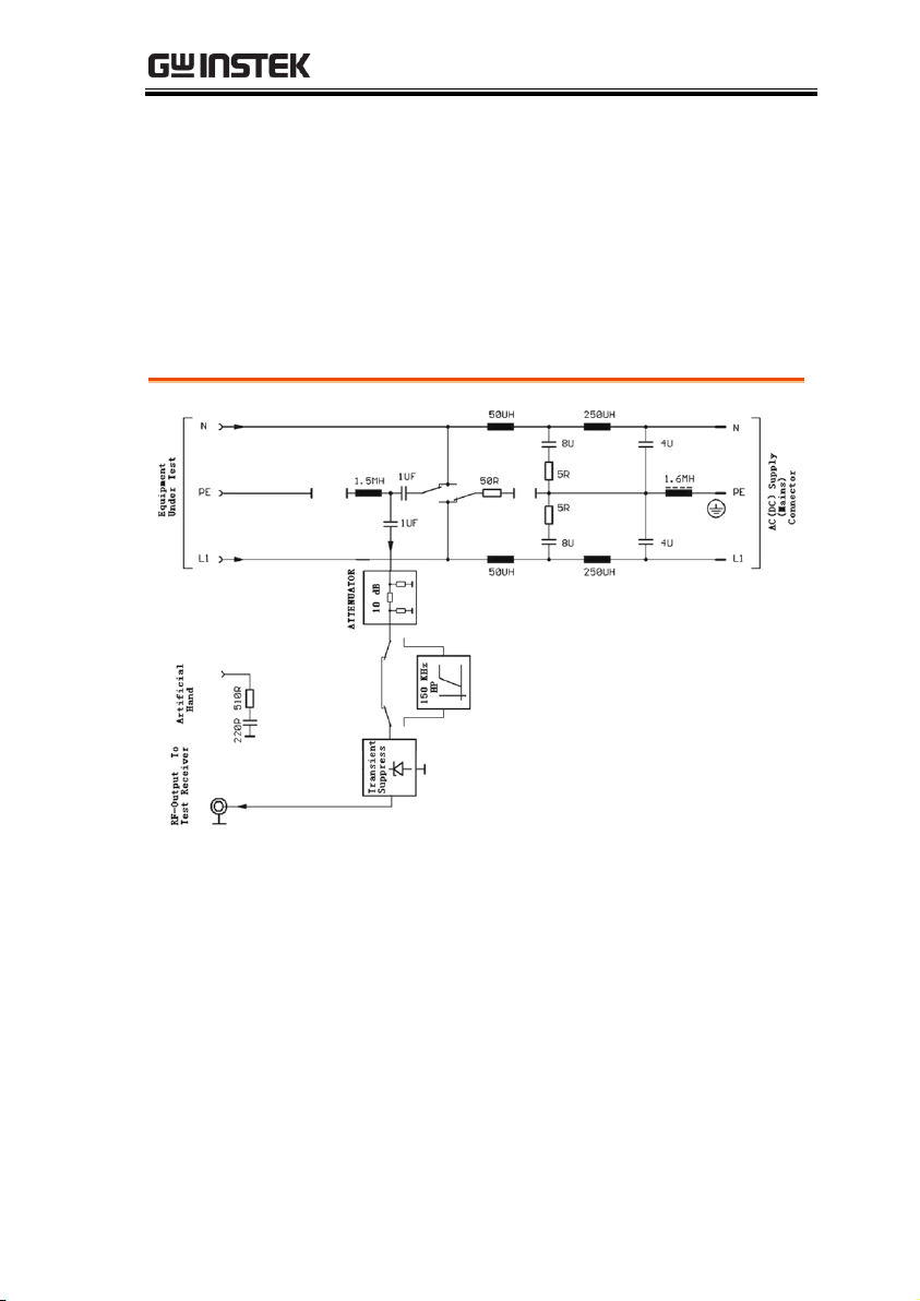
MAIN SCHEMATIC
DIAGRAM
7
Page 10

GLN-5040A User Manual
1. Artificial mains network must use the isolation
transformer to isolate to ensure personal safety.
2. The GLN-5040A must be grounded to ensure
personal safety, especially when there is no
isolation transformer connected. If the GLN5040A is not grounded it may lead to serious
electrical shock.
TEST EQUIPMENT SET-UP
Safety Cautions
8
Page 11

TEST EQUIPMENT SET-UP
Item
Description
1
Minimum 2mx2m metal board
2
(EUT) Equipment Under Test
3
Folding method for power supply wire length>1m
4
EUT power supply interface
5
Output shielded wire
A
Artificial Mains Network
B
Isolated Transformer
C
Receiver
Test Equipment Set-up Schematic Diagram
Non-handheld Equipment Conduction Testing Diagram
9
Page 12

GLN-5040A User Manual
Item
Description
1
Minimum 2mx2m metal board
2
(EUT) Equipment Under Test
3
Folding method for power supply wire length>1m
4
Artificial hand function connecting wires
5
ETU power supply interface
6
Artificial hand connecting terminals
7
Conducted interference signal output interface
8
Handheld metal parts, made up of several sections,
connected by conducting wires
9
Grounding terminal
10
Artificial mains network power supply interface
11
Input interface
12
BNC Cable
Handheld Equipment Conduction Testing Schematic Diagram (the ETU handheld part has metal shell, it is required to use artificial hand)
10
Page 13

TEST EQUIPMENT SET-UP
13
Power Supply Cable
A
Artificial Mains Network
B
Receiver
C
Isolated Transformer
11
Page 14

Set up
Procedure
1. Ground the GLN-5040A with the testing
receiver ground wire.
2. Connect the isolated transformer and the GLN-
5040A two line V-network.
3. Connect to the EUT; please place the equipment
with the reference to the above schematic
diagram.
4. Connect the GLN-5040A interference signal
output terminal to the EMI receiver input
terminal.
5. Select the correct filter for the testing standard.
6. Connect the GLN-5040A to the isolation
transformer, which is connected to the power
grid, and power on to test.
7. Use the phase line switch on the GLN-5040A to
select different phase lines during the test.
Note
When using the equipment, don't open the case,
don't in a humid, explosive or inflammable
environment. Please ensure the equipment
surface is dry and clean before use.
The maximum voltage should be under 50V
when using the AC power supply.
Please read the user manual carefully before
use to become familiar with the safety the
requirements and to test correctly.
It is recommended to use an isolation
GLN-5040A User Manual
12
Page 15

TEST EQUIPMENT SET-UP
transformer, in case of emergencies.
Please contact us if any problems occur. In case
of an accident, do not attempt to open the case
for repair.
13
Page 16

GLN-5040A User Manual
Frequency range
9kHz-30MHz
Line impedance
(50uH+5Ω)||50Ω V type, Two-Line VNetwork
Tested circuit phase number
Single phase
AC voltage range
0~240V AC+10%
AC frequency range
50~60Hz ±5%
DC voltage range
0~50V DC
Maximum permitted
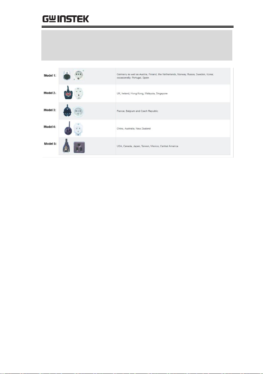
current(continuous) Countryspecific connector models
Refer to figure 1 or models
Model 1: For Germany(Schuko
connector)
16A
Model 2: For United Kingdom
13A
Model 3: For France
16A
Model 4: For China/Australia
10A
Model 5 For USA
15A
High-pass filter (alternative)
150kHz
Voltage division factor between
EUT and measuring receiver port
10dB
Response threshold of built-in
pulse limiter
130dBuV
RF output
BNC(female)/50Ω
Artificial hand function
Embodied
EUT power supply interface
German standard power supply socket
Working temperature range
+5°C ~+45°C
Storage temperature
-40°C ~+70°C
Safety standard
Confirm to EN61010
EMC
Confirm to EN61326
Size
338mm(L)×237mm(W)×133mm(H)
Weight
4.2kg
BNC coaxial cable
2m
APPENDIX
GLN-5040A Specifications
14
Page 17
APPENDIX
Certification
CE(EN61010-1:2010
EN61326-1:2013
EN61000-3-2:2014
EN61000-3-3:2013)
Figure 1 Country-specific connector models
15
 Loading...