

GW Instek GFG-8215A, GFG-8216A, GFG-8217A, GFG-8219A, GFG-8255A Instruction Manual
...
FUNCTION GENERATOR-SERIES
INSTRUCTION MANUAL
2
TABLE OF CONTENTS
1. SAFETY SUMMARY………………………………………. 1
2. INTRODUCTION…………………………………………… 5
3. SPECIFICATION……………………………………………. 7
4. FUNCTION DESCRIPTION.………………………………. 13
5. USAGE DESCRIPTION……………………………………. 17
6. APPLICATION NOTE……………………………………… 23
7. MAINTENANCE…………………………………………… 33
FUNCTION GENERATOR-SERIES
INSTRUCTION MANUAL
1
1.SAFETY TERMS AND SYMBOLS
Please take a moment to review these safety terms and symbols
which may appear in this manual or on Equipment to prevent damage
to the Function Generators.
WARNING. Warning statements identify condition or
practices that could result in injury or loss of life.
CAUTION. Caution statements identify conditions or
practices that could result in damage to this product or
other property.
FUNCTION GENERATOR-SERIES
INSTRUCTION MANUAL
2
DANGER High Voltage
ATTENTION refer to Manual
Protective Conductor Terminal
(ground) Earth Terminal
Frame or Chassis T erminal
FUNCTION GENERATOR-SERIES
INSTRUCTION MANUAL
3
FOR UNITED KINGDOM ONLY
NOTE: This lead/appliance must only be wired by
competent persons
WARNING: THIS APPLIANCE MUST BE EARTHED
IMPORTANT: The wires in this lead are coloured in
accordance with the following code:
Green/ Y ellow: Earth
Blue: Neutral
Brown: Live(Phase)
As the colours of the wires in main leads may not correspond
with the colours marking identified in your plug/appliance,
proceed as follows:
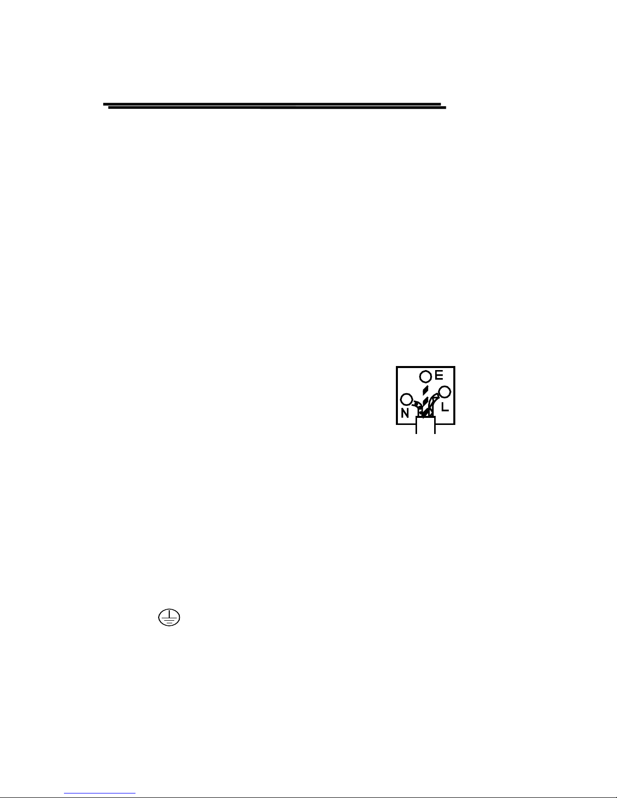
The wire which is coloured Green & Yellow must be connected
to the Earth terminal marked with the letter E or by the earth
symbol
or coloured Green or Green & Yellow.
The wire which is coloured Blue must be connected to the

FUNCTION GENERATOR-SERIES
INSTRUCTION MANUAL
4
terminal which is marked with the letter N or coloured Blue or
Black.
The wire which is coloured Brown must be connected to the
terminal marked with the letter L or P or coloured Brown or Red.
If in doubt, consult the instructions provided with the equipment
or contact the supplier.
This cable/appliance should be protected by a suitably rated
and approved HBC mains fuse : refer to the rating information
on the equipment and/or user instructions for details. As a
guide, cable
of 0.75mm² should be protected by a 3A or 5A fuse. Larger
conductors would normally require 13A types, depending on
the connection method used.
Any moulded mains connector that requires removal
/replacement must be destroyed by removal of any fuse & fuse
carrier and disposed of immediately, as a plug with bared wires
is hazardous if a engaged in live socket. Any re-wiring must be
carried out in accordance with the information detailed on this
label.

FUNCTION GENERATOR-SERIES
INSTRUCTION MANUAL
5
2. INTRODUCTION
The Function Generator series are stable low distortion instruments
which generate signals in the frequency range up to 5MHz. Typical
applications include a wide range of audio response testing applications,
vibration testing, servo system evaluation, ultra sound applications, and etc.
These instruments include the following features: logarithmic and lin ear
sweep capabilities, together with a built in frequency counter. The sweep
capability simplifies the task of finding resonant points of speakers, filter
networks and other networks/structures. An oscilloscop e may be connected
to this instrument for the response to be displayed. The counter can be
switched to measure and display the frequency of an external signal up to
150MHz.
z ADDITIONAL FEAT U RES
1.Low distortion wa veforms (sine, trian g ula r an d square) and ram p sig nal .
2.Signal output in seven deca de stages , 0. 5Hz to 5M Hz f or GFG -8250 A/ 8 255A ,
0.3Hz to 3MHz for GFG-8215A/8216A/8217A/8219A.
3.Adjustable sweep time and sweep width both in linear and logarithmic
modes.
4.Duty cycle control with signal inversion capability.
5.External Voltage controlled F req uency (VCF).
6.AM or FM modulat i o n modes with internal or external modulatio n control.

FUNCTION GENERATOR-SERIES
INSTRUCTION MANUAL
6
7.A second output for TTL or adjustable CMOS pulses.
8.50 ohm main signal output with DC offset adjustment and 20dB attenuation
capability .
9. Supplied with two BNC test leads and AC power cord set.
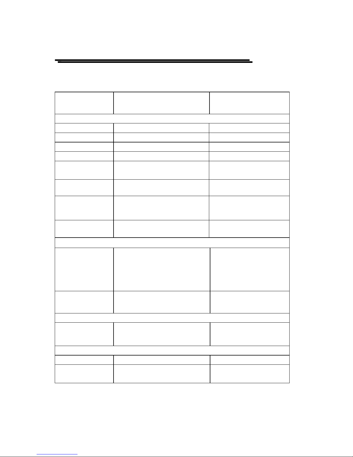
z FEATURES COMPARISON TABLE FOR MODELS:
MODEL
FEATURE
GFG-
8215A
GFG-
8216A
GFG-
8217A
GFG-
8219A
GFG-
8250A
GFG-
8255A
AM/FM
───ˇ─ˇ
SWEEP
──ˇˇ─ˇ
COUNTER
─ˇˇˇˇˇ
GCV Output
───ˇ─ˇ
TTL/CMOS
ˇˇˇˇˇˇ
VCF
ˇˇˇˇˇˇ
Duty Cycle
Control
ˇˇˇˇˇˇ
FUNCTION GENERATOR-SERIES
INSTRUCTION MANUAL
7
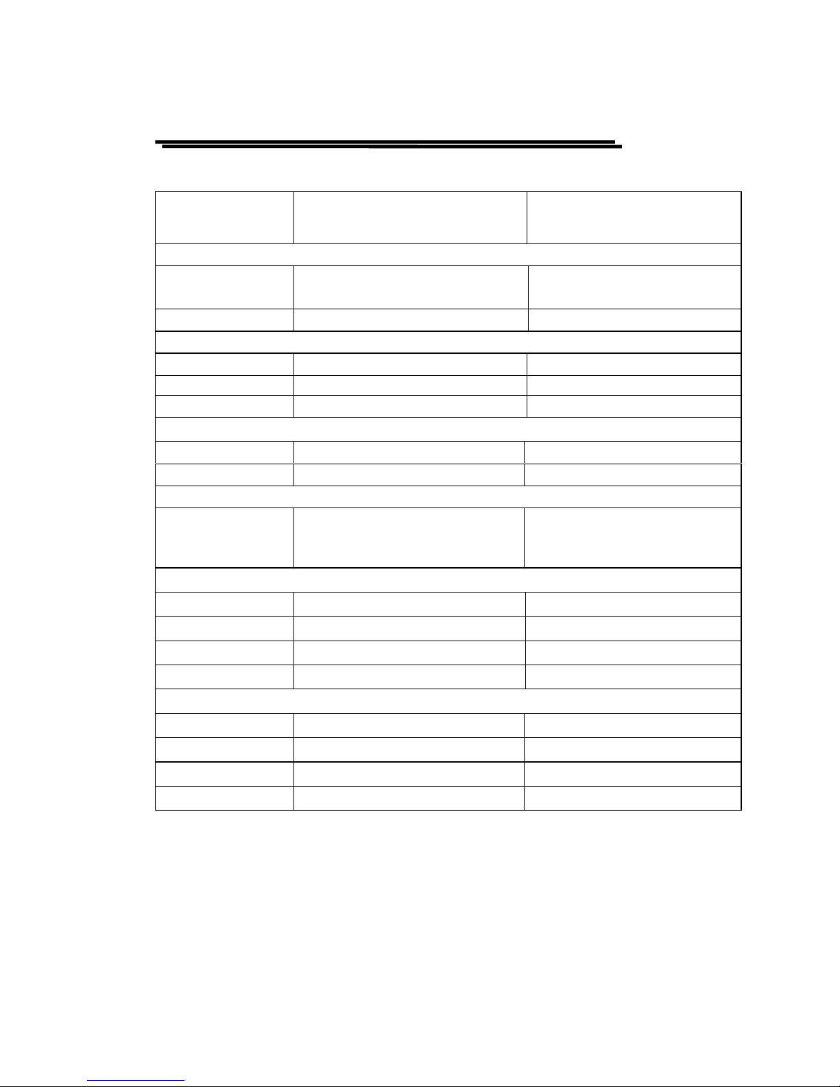
3. SPECIFICATION
GFG-
8215A/8216A/8217A/8219A
GFG-
8250A/8255A
1.Main
Frequency Range
0.3Hz~3MHz(7 Range) 0.5Hz~5MHz(7 Range)
Amplitude
≧10Vpp(into 50Ωload) ≧10Vpp(into 50Ωload)
Impedance
50Ω±10% 50Ω±10%
Attenuator
-20dB±1dB×2 -20dB±1dB×2
DC Offset
<-5V~>5V
(into 50Ωload)
<-5V~>5V
(into 50Ωload)
Duty Control
80%:20%:80% to 1MHz
Continued variable
80%:20%:80% to 1MHz
Continued variable
Display
6 digits LED display
*GFG-8215A does not have
display.
6 digits LED display
Range Accuracy
±5%+1Hz(at 3.0 position)
*only for GFG-8215A.
----------------------------
2.Sine W ave
Distortion
≦1%,0.3Hz~200kHz ≦1%,0.5Hz~100kHz
Flatness
<0.3dB,0.3Hz~300kHz
<0.5dB,300kHz~3MHz
≦0.3dB,below 500kHz
≦1dB,below 5MHz
3.T r iangle Wave
Linear
≧98%,0.3Hz~100kH z
≧95%,100kHz~3MHz
≧98%,0.5Hz~100kH z
≧95%,100kHz~5MHz
4.Square Wave
Symmetry
±2%,0.3Hz~100kH z ±2%,1Hz~100kHz
Rise or Fall Time
≦100ns at maximum output.
(into 50Ωload)
≦50ns at maximum output
(into 50Ωload)
FUNCTION GENERATOR-SERIES
INSTRUCTION MANUAL
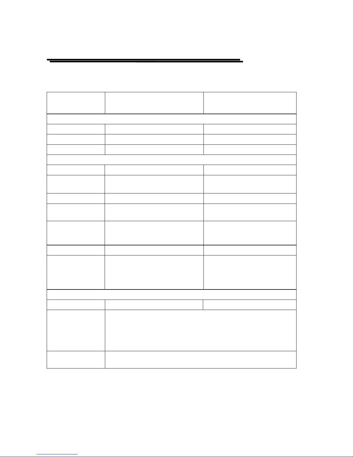
8
GFG-
8215A/8216A/8217A/8219A
GFG-
8250A/8255A
5.CMOS Output
Level
4Vpp±1Vpp~14.5Vpp
±0.5Vpp adjustable
4Vpp±1Vpp~14.5Vpp
±0.5Vpp adjustable
Rise or Fall Time
≦120ns ≦120ns
6.TTL Output
Level
≧3Vpp ≧3Vpp
Fan Out 20 TTL load 20 TTL load
Rise or Fall Time
≦25ns ≦25ns
7.VCF
Input voltage
0V~10V±1V(100:1) 0V~10V±1V(100:1)
Input Impedance
10kΩ±10% 10kΩ±10%
8.GCV(for GFG-8219A/8255A only)
Output voltage
To set the voltage betwee n
0V~2V as per dif ferent
frequency.
To set the voltage betwee n
0V~2V as per dif ferent
frequency.
9.Sweep Operation(for GFG-8217A/8219A/8255A only)
Sweep/Manual Switch selector Switch selector
Sweep/Rate 100:1 ratio max. and adjustab le 100:1 ratio max. and adjustable
Sweep/Time
0.5Sec~30Sec adjustable 0.5Sec~30Sec adjustable
Sweep/Mode Lin./Log. switch selector Lin./Log. switch selector
10.Amplitude Modulation(for GFG-8219A/8255A only)
Depth
0~100% 0~100%
MOD.Freq.
400Hz(INT),DC~1MHz(EXT) 400Hz(INT),DC~1MHz(EXT)
Carrier BW
100Hz~3MHz(-3dB) 100Hz~5MHz(-3dB)
EXT Sensitivity
≦10Vpp for 100% modulation ≦10Vpp for 100% modulation
FUNCTION GENERATOR-SERIES
INSTRUCTION MANUAL
9
GFG-
8215A/8216A/8217A/8219A
GFG-
8250A/8255A
11.Frequency Modulation (for GFG-8219A/8255A only)
Deviation
0~±5% 0~±5%
MOD.Freq.
400Hz(INT),DC~20kHz(EXT) 400Hz(INT),DC~20kHz(EXT)
EXT Sensitivity
≦10Vpp for 10% modulation ≦10Vpp for 10% modulation
12.Frequency Counter
Int./Ext. Switch selector Switch selector
Range
0.3Hz~3MHz
(5Hz~150MHz EXT)
0.5Hz~5MHz
(5Hz~150MHz EXT)
Accuracy
Time base accurac y±1count Time base accuracy±1count
Time base
±20ppm(23℃±5℃) after
30 minutes warm up
±20ppm(23℃±5℃) after
30 minutes warm up
Resolution
The maximum resolution is
10nHz
for 1Hz and
0.1Hz for 100MHz.
The maximum resolution is
10nHz for 1Hz and
0.1Hz for 100MHz.
Input Impedance
1MΩ/150pF 1MΩ/150pf
Sensitivity
≦35mVrms(5Hz~100MHz)
≦45mVrms(100MHz~150MHz)
*GFG-8215A does not have
Frequency Counter function.
≦35mVrms(5Hz~100MHz)
≦45mVrms(100MHz~150MHz)
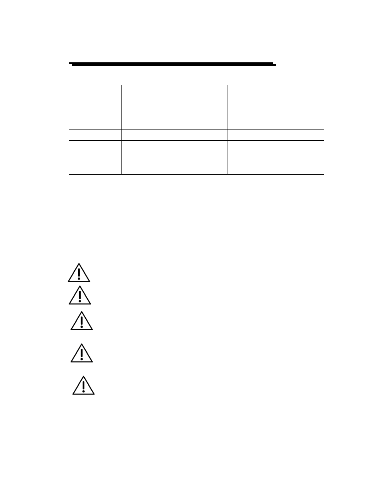
13.General
Power Source
AC115V, 230V±15%,50/60Hz AC115V, 230V±15%,50/60Hz
Operation
Environment
Indoor use, altitude up to 2000m.
Ambient T em perature 0℃ to 40℃.
Relative Humidity 80%(Maximum).
Installation category II
Pollution Degree 2
Storage temperature
& Humidity
-10℃ to 70℃.
70% (Maximum).
FUNCTION GENERATOR-SERIES
INSTRUCTION MANUAL
10
GFG-
8215A/8216A/8217A/8219A
GFG-
8250A/8255A
Accessories
GTL-101×2
*GTL-101×1 for GFG-8215A
Instruction manual×1
GTL-101×2
Instruction manual×1
Dimension
251(W)×91(H)×291(D) m/m 251(W)×91(H)×291(D) m/m
Weigh
Approx. 2.0kgs-GFG-8215A
2.1kgs-GFG-8216A
2.15kgs-GFG-8217A
2.2kgs-GFG-8219A
Approx. 2.3kgs-GFG-8250A
2.4kgs-GFG-8255A
Measurement category I is for measurements performed on circuits not
directly connected to MAINS.
Measurement category II is for measurements performed on circuits directly
connected to the low voltage installation.
Measurement category III is for measurements performed in the building
installation.
Measurement category IV is for measurements performed at the source of
the low-voltage installation
.
WARNING : To avoid electrical shock, the power cord
protective grounding conductor mu st be connected to gr ou nd .
CAUTION:To avoid damaging the instrument, do not use it
In a place where ambient temperature exceeds 40℃.
CAUTION:To avoid damaging the instrument, do not in put
more than DC15V to V.C.F.(V.C.G.).
CAUTION:To avoid damaging the instrument, do not in put
more than AC150V to Frequency Counter (for GFG-8216A,
GFG-8217A, GFG-8219A, GFG-8250A, and GFG-8255A).
CAUTION:To avoid damaging the instrument, do not in put
more than AC10Vpp when proceed EXT modulation
operation (for GFG-8219A, GFG-8255A).
FUNCTION GENERATOR-SERIES
INSTRUCTION MANUAL
11
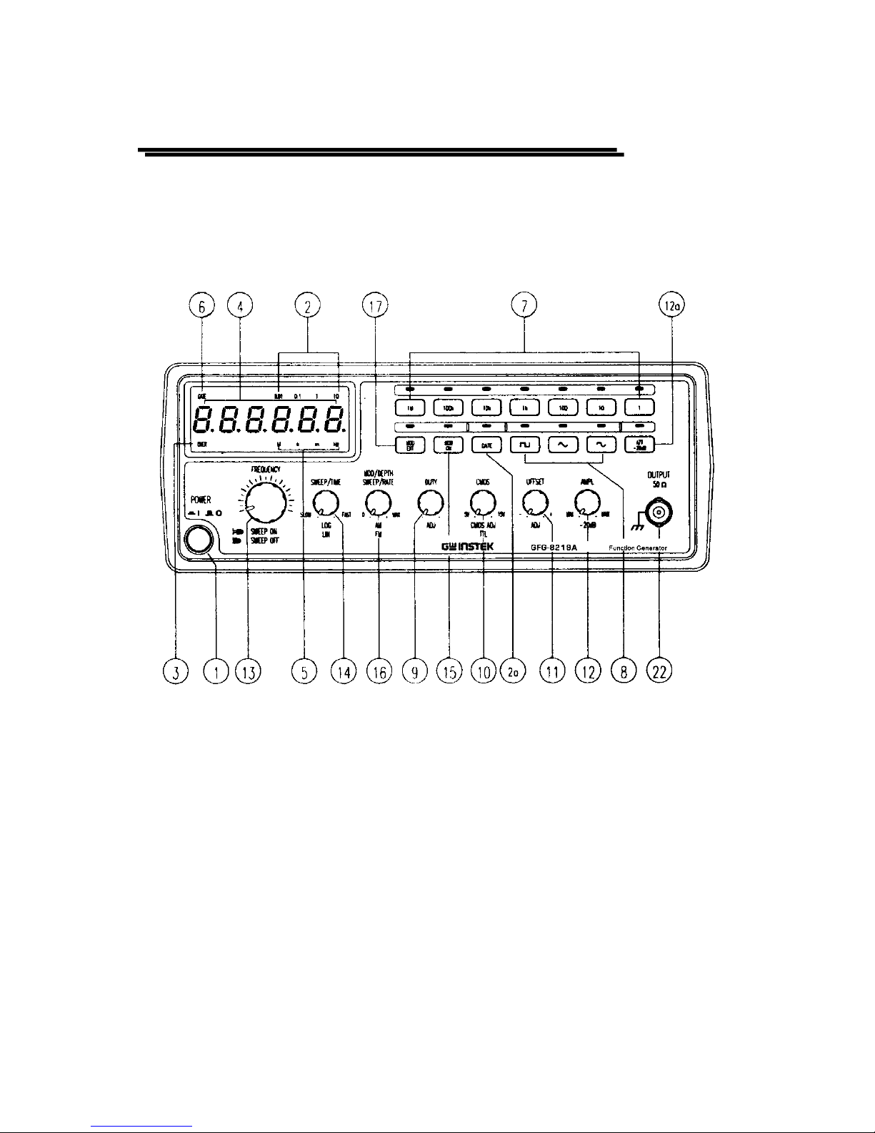
z Fig 4.1 FRONT PANEL
 Loading...