

Grundig UZ 2400 User Manual

CONTENTS
1 General Information 3
1.1
Safety Instructions 3
1.2 Switching the Operating Voltage 230 V~/115 V~ 3
1.3 Mains Connection 4
1.4 Installing the Power Supply Unit 4
1.5 Switching on 4
1.6 EMC 4
1.7 Inspection and Maintenance 4
1.8 Warranty 5
1.9 Accessories Supplied 5
2 Application 6
3 Set-up and Functional Description 7
3.1 Block Diagram 7
3.2 Description 7
4 Technical Data 8
4.1 General Data 8
4.2 Specifications 8
4.2.1 Characteristics of Channel A 8
4.2.2 Characteristics of Channel C 9
4.3 Functions 9
4.3.1 Diagnostic Unit Function “CHK” 9
4.3.2 Frequency Measurement on Channel A “FRA” 9
4.3.3 Frequency Measurement on Channel C “FRC” 9
4.3.4 Period Length Measurement on Channel A “PER” 9
4.3.5 Simple Pulse Counting On Channel A “TOT” 10
4.4 Time Base 10
4.5 Display 10
4.6 Interface RS-232C 11
5 Control Elements 12
6 Realization of Measurements 14
6.1 Starting 14
6.1.1 Settings for Channel A 14
6.2 Frequency Measurement (FRA, FRC) 14
6.3 Period Length Measurement 14
1
Operating Instructions UZ 2400
1/2000

6.4 Simple Pulse Counting 15
6.5 Error Messages 15
7 Remote Control by Program 16
7.1 General Information 16
7.2 Preparation on the Counter 16
7.2.1 Test of the Data Transmission Line 16
7.2.2 Preparations for the Remote Control 16
7.2.3 Transition: Remote Control ⇔ Local Control 17
7.3 Messages of the Unit on Remote Control 17
7.3.1 Description of the Unit State 17
7.3.2 Description of the Result 17
7.3.3 Description of the Unit Settings 17
7.3.4 Description of the Error 18
7.4 Overview of Commands on Remote Control 18
7.4.1 Group of Common Commands 18
7.4.2 Group of Commands for Reading the Unit Settings 19
7.4.3 Group of Commands for Setting the Unit Functions 19
7.4.4 Group of Commands for Setting the Measurement Parameters 19
7.5 Status Byte 20
7.6 Measuring by Remote Control 20
7.7 Program Example (Q Basic) 21
8 Maintenance 22
9 Appendix 23
9.1 List of Messages on Display 23
9.2 Declaration of Conformity 24
2
Operating Instructions UZ 2400
1/2000
1 General Information
1.1
Safety Instructions
Wherever you see this sign
you will find information on potential hazards. Please
read these sections with particular care!
Warning! Before opening the instrument disconnect the mains plug!
Attention! If the fuse has to be changed, use only G fuse-link 5 × 20 according to
IEC 127 (see 4.1)!
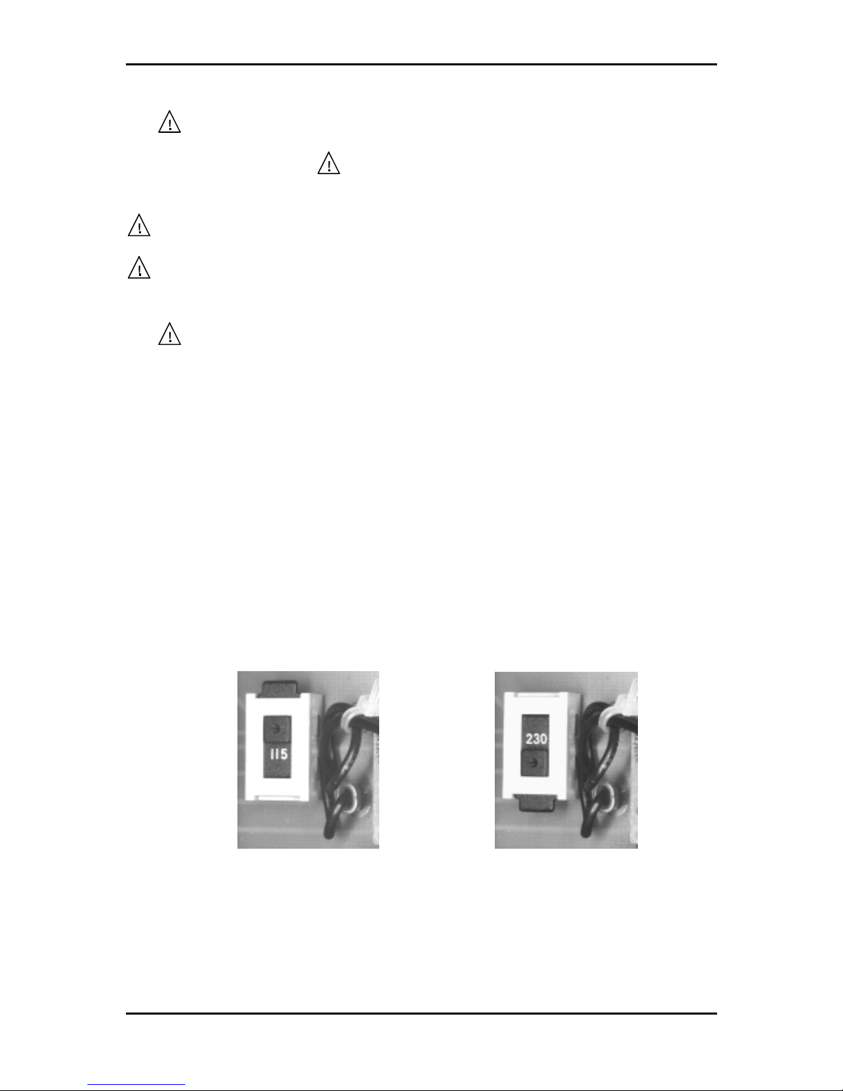
1.2 Switching the Operating Voltage 230 V~/115 V~
Your instrument left the factory to 230 V~. Switching to 115 V~ requires the instrument to be
opened, which should only be done by trained personnel.
Setting the Operating Voltage 115 V~
1. Disconnect the instrument from the mains.
2. Remove upper caps and loosen the screws below.
3. Identify the mains voltage switch with the following illustration.
4. Switch the voltage mains voltage switch (slide switch) located under the power switch to
the indication “115”.
5. Remove safety cover at the mains plug and replace the fuse with the fuse for 115 V
supplied with the instrument.
6. Fasten upper caps and put the sticker supplied with the instrument for marking the switch-
over to 115 V on to the type label.
Mains Voltage Switch
115 V position 230 V position
3
Operating Instructions UZ 2400
1/2000

1.3 Mains Connection
The design of the unit meets the requirements of safety class I according to EN 61010-1, i. e.
all metal parts accessible from outside and exposed to contact are connected with the
protective conducto of the supply network.
Power is supplied via a mains cable with earthing contact.
1.4 Installing the Power Supply Unit
The unit should not be operated close to equipment that develops heat.
1.5 Switching on
The unit is switched on using the power switch at the front. The power switch separates the
unit completely from the primary side of the transformer.
The LED ON/OFF serves as an operation indicator.
1.6 EMC
The unit is interference-free according to the EN 50081-1 and EN 50081-2. In order to fulfil
the limiting values in line with present standards, it is absolutely necessary that only cables
which are in perfect condition be connected to the unit. The following information applies
here:
− Metallic or metallized socket cases must be used for interface RS-232C. The socket cases
and the braided screen of the cables must be connected at the shortest distance possible.
The signal earth must not be connected to the braided screen.
− After opening and closing the unit ensure that if all the fixing parts and contact springs are
installed as before that all the screws are fixed and tightly.
1.7 Inspection and Maintenance
If service is needed, due attention should be paid to the regulations according to VDE 0701.
The unit should only be repaired by trained personnel.
4
Operating Instructions UZ 2400
1/2000

1.8 Warranty
GRUNDIG guarantees the perfect working order of the unit for 12 months as from delivery.
There is no warranty for faults arising from improper operation or from changes made to the
unit or from inappropriate application.
If a fault occurs please contact or send your unit to:
The unit should be sent in appropriate packing - if possible in the original packing. Please
enclose a detailed fault report (functions working incorrectly, deviating specifications and so
on) including unit type and serial number.
Kindly verify warranty cases by enclosing your supply delivery note. Any repairs carried out
without reference to a valid warranty will initially be at the owner’s expense.
Should the warranty have expired, we will, of course, be glad to repair the unit as per our
General Terms Of Assembly And Service.
1.9 Accessories Supplied
1 mains cable
2 fine wire fuses (T 200 mAL/250 V and T 100 mAL/250 V)
1 coaxial cable
1 operating instructions
1 sticker of marking for 115 V switch-over
5
Operating Instructions UZ 2400
1/2000

2 Application
• The table measuring unit UZ 2400 is a compact two-channel counter controlled by a
microprocessor and allows frequency measurements of period signals via channel A within
the range of 10 Hz to 100 MHz and via channel C from 50 MHz to 2.4 GHz.
• Moreover, the period length of periodic signals from 100 µs to100 ms can be measured
within the range of and pulses can be counted from 1 to 10
9
pulses via channel A.
• The trigger level can be set and measuring amplitudes up to 50 V can be attenuated at the
ratio of 10:1 on channel A.
• Functions and measuring ranges can be set by means of 4 buttons in the form of a menu
and they are clearly depicted on a 16-digit display.
• The unit is supplied with a serial interface RS-232C which allows both remote control and
a further processing of the data.
6
Operating Instructions UZ 2400
1/2000
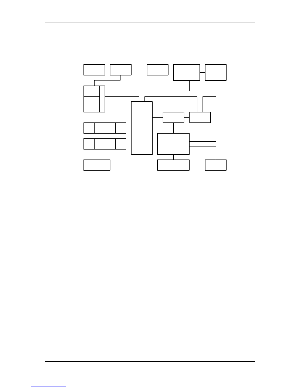
3 Set-up and Functional Description
3.1 Block Diagram
1
2
3
18 22
4
5
146
78
9
10 11 12 13
15 16
17
21 20 19
A
C
Time Base ShaperPulse GeneratorProcesso
r
RS-232C
Counte
r
Divide
r
Pre-Steps
Pre-Steps
Power Suppl
y
Control Logic
Displa
y
Interface
Ke
y
boar
d
Divider 1:10
3.2 Description
The unit's internal measuring operation is controlled by a one-chip microprocessor MCS-51
with the help of additional circuits. The processor [18] which gets its time frequency from the
pulse generator [3] can also communicate with superior systems via the serial interface [22].
The time base which is supplied with the standard frequency of 10 MHz [1] provides precise
frequencies for single measuring intervals. The standard frequency is led to a special circuit
via the shaper [2]. This circuit contains an internal predivider of 1:10 [4] and a programmable
dividing decade [5]. Furthermore it provides reference frequencies of 1 MHz and 10 MHz.
The generated measuring intervals are led on the input of the switch- and control logic [14].
The measuring signal passing through channel A is led to a Schmitt-trigger [8] after being set
[6] and boosted [7], and, subsequently, it is converted from ECL to TTL level [9]. This signal
also is led to the input of the switch- and control logic.
The measuring signal passing through channel C is also set and boosted [10, 11], and led to a
fast divider [12] and converted from ECL to TTL. Before passing the switch- and control
logic the high-frequency signal is divided further [13].
The signal gated in [14] is led to a high-speed predivider of 1:10 [15] which is counted by a
decadic counter [16] and shown on an alphanumeric LCD-display [19]. The processor,
thereby, organizes the reading of the keyboard [20], the setting of the control logic, the
resetting of the counting decades and the repetition of the measurement by means of the
interface circuit [17].
7
Operating Instructions UZ 2400
1/2000

4 Technical Data
4.1 General Data
Rated temperature: + 23 °C ± 2 °C
Operational temperature: + 5 to + 40 °C
Relative humidity: 20 ... 80 %
Atmospheric pressure: 86 ... 106 kPa
Operational position: horizontal or inclined by ± 15 °
Operational voltage: sinusoidal alternating voltage (distortion factor < 5 %)
115/230 V ± 10 % (internal switchable)
Frequency: 50 ... 60 Hz (± 5 %)
Power input: 20 VA
Fuses: T 100 mAL/250 V (230 V~)
T 200 mAL/250 V (115 V~)
Safety class: 1, according to EN 61010 Part 1
Radio interference suppression: EN 55011 Class B
Dimensions (L × H × D): 225 mm × 85 mm × 200 mm
Dimensions of packing: 310 mm × 110 mm × 265 mm
Weight:
of universal counter approx. 1.8 kg
incl. packing and accessories: approx. 2.6 kg
4.2 Specifications
4.2.1 Characteristics of Channel A
Frequency range: 10 Hz ... 100 MHz
Basic sensitiveness:
= 25 mV (sinusoidal signal) V
rms
(Voltage divider 1:1): = 75 mV on pulses with minimal width of ≥ 10 ns V
pp
Coupling: alternating voltage
Input impedance: 1 M
Ω (< 20 pF)
Input divider: 1:1 or 10:1
Dynamic range: 75 mV ≤ V ≤ 5 mV
pp
(with divider 10:1): 750 mV
≤ V ≤ 50 mV
pp
Maximum input voltage: 50 V (V = + V
) with divider 10:1
pp
8 V with divider 1:1, f > 50 kHz
Trigger level setting: adjustable by potentiometer
(voltage divider 1:1) + 0.5 ... – 0.5 V
(voltage divider 10:1) + 5 ... – 5 V
8
Operating Instructions UZ 2400
1/2000
 Loading...