

Page 1

HIFI STEREO MICRO SYSTEM
ǵ
ENGLISH
VERTIGA
UMS 5100
72011-400.4900
Page 2

2
CONTENTS
________________________________________________________________________
3 Set-up and safety
4 Overview
Operating elements of the stereo system
The back of the stereo system
The remote control
9 Connection and preparation
12 Settings
Setting the clock
Tuning to radio stations
Storing radio stations
Deleting settings
15 General functions
17 Tuner mode
RDS station service
20 CD mode
Basic CD mode functions
Special CD mode features
Creating a track memory – playing back tracks in selected order
25 Timer mode
Setting the switch-on timer
Setting the sleep timer
27 Information
Cleaning the CD unit
Technical data, rectifying minor problems
GRUNDIG Service
Page 3

ENGLISH
3
ENGLISH
SET-UP AND SAFETY
______________________________________________
Please note the following information when setting up the system:
This stereo system is designed for the playback of audio signals. Any other use
is expressly prohibited.
Please note when setting up the stereo system that furniture surfaces are coated
with various types of paint and plastic, which often contain chemical additives.
These additives may cause corrosion to the feet of the unit. This may leave stains
on the surface of the furniture which can be difficult or impossible to remove.
If the stereo system is exposed to sudden changes in temperature, for example
when taken from the cold into a warm room, wait at least two hours before
using it.
The stereo system is designed for use in dry rooms. If you do use it in the open,
please ensure that it is protected from moisture, such as rain or water splashes.
Do not place the stereo system close to heating units or in direct sunlight, as this
will impair cooling.
Do not place any vessels such as vases on the stereo system. Do not insert any
foreign bodies in the CD compartment.
Do not open the stereo system under any circumstances. The manufacturer
accepts no liability for damage resulting from improper handling.
Thunderstorms are a danger to all electrical devices. Even if the stereo system is
switched off, it can be damaged by a lightning strike to the mains or the
antenna cable. Always disconnect the mains and antenna plugs during a storm.
! SERVICE !! SERVICE !
°C
2h
°C
OPTICAL
DIGITAL OUT
SPEAKERS
IMPEDANCE MIN 4Ω
! SERVICE !
OPTICAL
DIGITAL OUT
SPEAKERS
IMPEDANCE MIN 4Ω
L
R
AC IN
˜
LINE IN (AUX)
RRL
L
LINE OUT
ANTENNA
COA-
FM
XIAL
EXT
75Ω
L
R
AM
AM
EXT
LOOP
AC IN
˜
LINE IN (AUX)
RRL
L
LINE OUT
ANTENNA
COA-
FM
XIAL
EXT
75Ω
AM
AM
EXT
LOOP
Page 4

4
OVERVIEW
_______________________________________________________________________
Operating elements of the stereo system
Operating controls on the front
ON/OFF Switches the stereo system to and from
stand-by mode.
O Infrared receiver for remote control sig-
nals.
• Stand-by indicator.
PHONES Headphone jack for connecting a stereo
headphone set with a jack plug
(ø 3.5 mm). The loudspeakers of the stereo system are automatically switched
off.
– VOLUME + Adjusts the volume.
Operating controls on the top of the
system
TIMER/
SNOOZE
For setting the switch-on timer
Delays the alarm for approximately
5 minutes.
CLOCK For setting the clock.
SLEEP For setting the sleep timer.
X-BASS
For boosting the bass.
DSC Selects the sound settings.
Page 5

ENGLISH
5
ENGLISH
OVERVIEW
__________________________________________________________________________________
AUX operation
AUX Selects the input source »AUX« (external
device).
Radio mode
TUNER Selects the » TUNER« input source.
BAND Selects the frequency band »FM« or
»MW«.
ıı
s6
Hold down to start the station search.
5a
ľľ
Press briefly to change the frequency in
small steps.
NEXT PRESET Selects preset stations.
CD mode
CD/ıII Selects the »CD« input source.
Starts and interrupts CD playback.
■ Ends CD playback.
Deletes the track memory for the CD.
ıı
s6
Press briefly to select the next track.
Hold down to look for a particular passage.
5a
ľľ
Press briefly to select the previous track.
Hold down to look for a particular passage.
ə
Opens and closes the CD compartment.
Page 6

6
OVERVIEW
__________________________________________________________________________________
The back of the stereo system
ANTENNA FM Socket for the rooftop antenna
EXT or the wire antenna supplied.
ANTENNA AM Antenna terminals for the wire antenna
EXT supplied.
OPTICAL Digital output for copying a CD onto a
DIGITAL OUT digital recording device.
LINE IN (AUX) Audio signal input for an external devi-
ce.
LINE OUT Audio signal output for an external devi-
ce.
SPEAKERS
Connections for the loudspeakers
RL + RL–
supplied.
R
= right channel, L= left channel.
~ AC IN Socket for power cord.
The only way to separate the stereo
system from the mains is to pull out the
mains plug.
General instructions for laser devices
The laser installed in the device conforms to LASER CLASS 1 and is designed to
ensure that the maximum permissible emission value cannot be exceeded under
any circumstances.
Caution:
If operating devices or methods other than those specified here are
employed, it may lead to dangerous exposure to emissions. Invisible laser
radiation is emitted if the CD compartment is opened or the safety locking
mechanism is shorted. Do not expose yourself to this radiation.
OPTICAL
DIGITAL OUT
SPEAKERS
IMPEDANCE MIN 4Ω
R
AC IN
˜
LINE IN (AUX)
R
L
R
ANTENNA
COAXIAL
75Ω
L
AM
LOOP
LINE OUT
L
FM
EXT
AM
EXT
Page 7

ENGLISH
7
ENGLISH
OVERVIEW
__________________________________________________________________________________
The remote control
9 Switches the stereo system to and from stand-by mode.
TIMER
SNOOZE
For setting the switch-on and sleep timers.
CLOCK For setting the clock.
1...0, +10
Numeric keys for various inputs.
To select preset stations 10 to 20, first press »+10«, then
enter the two digit station number using »0...9«.
SLEEP For setting the sleep timer.
PROGRAM In tuner mode – stores preset stations and starts the
AUTO PRESET automatic search programming.
In CD mode – stores a track memory.
REPEAT In tuner mode – switches stereo broadcasts from stereo
STEREO/MONO to mono reception.
In CD mode – repeats a track or the entire CD.
RANDOM In CD mode – activates the playback of tracks in random
order.
CT In tuner mode – selects the RDS time.
RDS In tuner mode – selects the RDS mode.
DISPLAY In tuner mode – calls up various information on the display.
CLOCK
1
4
7
0
PROGRAM
AUTO PRESET
CT
DSC
AUX
TIMER
SNOOZE
2
5
8
+
10
REPEAT
STEREO/MONO
RDS
MUTE
CD
VOLUME
6
3
6
9
SLEEP
RANDOM
DISPLAY
X-BASS
BAND
TUNER
ǵ
Page 8

8
OVERVIEW
__________________________________________________________________________________
DSC Selects the sound settings.
MUTE Switches the loudspeaker on and off again.
X-BASS For boosting the bass.
AUX Selects the input source »AUX«.
CD
ıII In CD mode – starts CD playback, pauses playback.
BAND TUNER Selects the input source »TUNER« and selects the frequency
bands »FM« or »MW«.
5a
ľľ
In tuner mode – press briefly to change the frequency
ıı
s6
in small steps. Hold down to start the station search.
In CD mode – press briefly to select a track.
Hold down to search for a particular passage.
■ In CD mode – ends playback of the CD.
+ VOLUME –
Adjusts the volume.
CLOCK
1
4
7
0
PROGRAM
AUTO PRESET
CT
DSC
AUX
TIMER
SNOOZE
2
5
8
+
10
REPEAT
STEREO/MONO
RDS
MUTE
CD
VOLUME
6
3
6
9
SLEEP
RANDOM
DISPLAY
X-BASS
BAND
TUNER
ǵ
Page 9
ENGLISH
9
ENGLISH
CONNECTION AND PREPARATION
_______
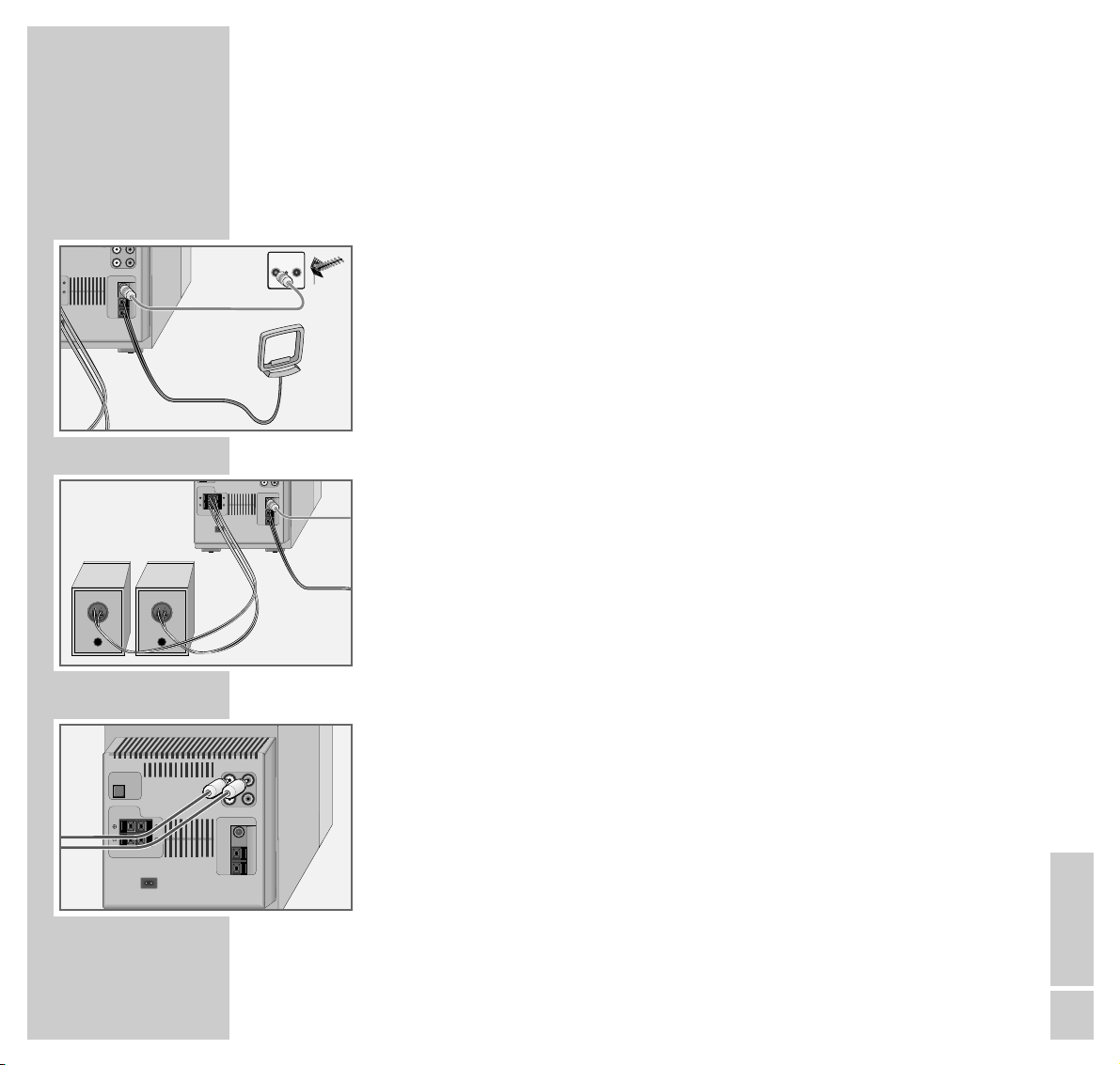
Connecting the antenna
1 Insert the rooftop antenna in the »ANTENNA FM EXT« socket on the
stereo system.
Note:
If no rooftop antenna system is available, use the auxiliary antenna supplied.
This antenna provides reasonably good reception of local FM (VHF) stations.
Do not shorten the auxiliary antenna.
2 Insert the wire antenna into the »ANTENNA AM EXT« terminals on the
stereo system. Adjust the position of the wire antenna until reception is at its
best.
Connecting the loudspeakers
1 Connect the loudspeaker cables to the »SPEAKERS RL + RL –« terminals
on the stereo system and the »+ INPUT –« terminals on the loudspeakers.
Connect the cables labelled in red to »+«.
Connecting an external device
1 Connect the audio output sockets of the external device (for example a
television or DVD player) to the »LINE IN (AUX)« sockets on the stereo
system using a cinch cable.
Note:
Switch the stereo system off before you connect external devices. Make sure
the stereo channels are properly connected:
R = right channel (red), L = left channel (white).
RRL
RL
LINE OUT
ANTENNA
COA-
FM
XIAL
EXT
75Ω
AM
AM
EXT
LOOP
TVR
L
LINE OUT
ANTENNA
COA-
FM
XIAL
EXT
75Ω
AM
AM
EXT
LOOP
N
SPEAKERS
IMPEDANCE MIN 4Ω
L
R
AC IN
˜
OPTICAL
DIGITAL OUT
SPEAKERS
IMPEDANCE MIN 4Ω
R
LINE IN (AUX)
R
L
R
L
LINE OUT
ANTENNA
COA-
FM
XIAL
EXT
L
AC IN
˜
75Ω
AM
AM
EXT
LOOP
Page 10

10
CONNECTION AND PREPARATION
_______________________________________
Connecting a digital recording device
1 Use an OPTICAL cable to connect the »DIGITAL OPTICAL OUT« jack on
the stereo system to the appropriate jack on the external device (e.g. MD or
CDR).
Note:
This socket enables you to record CD playback with a digital recording
device.
Connecting headphones
1 Insert the headphone plug (ø 3.5 mm) into the »PHONES« socket on the
front of the stereo system.
– The loudspeakers of the stereo system are switched off.
Connecting the power cord
Note:
Check that the mains voltage on the type plate (on the back of the device)
corresponds to your local mains supply.
The only way to disconnect the device from the mains supply is to pull out the
plug.
1 Plug the mains cable supplied into the »~AC IN« socket on the device.
2 Insert the mains cable plug into the mains socket.
U
OPTICAL
DIGITAL OUT
SPEAKERS
IMPEDANCE MIN 4Ω
LINE IN (AUX)
RRL
L
LINE OUT
ANTENNA
COA-
FM
XIAL
EXT
L
R
AC IN
˜
75Ω
AM
AM
EXT
LOOP
ME +
PHONES
LINE IN (AUX)
OPTICAL
DIGITAL OUT
SPEAKERS
IMPEDANCE MIN 4Ω
L
R
AC IN
˜
RRL
LINE OUT
ANTENNA
COAXIAL
75Ω
AM
LOOP
L
FM
EXT
AM
EXT
Page 11

CONNECTION AND PREPARATION
_______________________________________
ENGLISH
11
Important notes for users in the U.K.
Mains plug
This apparatus is fitted with an approved moulded 13 Amp plug. To change a fuse in this
type of plug proceed as follows:
1 Remove fuse cover and fuse.
2 Fix new fuse which should be a BS1362 5 Amp, A.S.T.A. or BSI approved type.
3 Refit the fuse cover.
If the fitted plug is not suitable for your socket outlets, it should be cut off and an
appropriate plug fitted in its place.
If the mains plug contains a fuse, this should have a value of 5 Amp. If a plug without a
fuse is used, the fuse at the distribution board should not be greater than 5 Amp.
Note:
The severed plug must be disposed to avoid a possible shock hazard should it be
inserted into a 13 Amp socket elsewhere.
How to connect plug
The wires in the mains lead are coloured with the following code: blue = neutral (N),
brown = live (L).
As these colours may not correspond with the colour markings identifying the terminals
in your plug, proceed as follows:
1 Connect the blue wire to the terminal marked N or coloured black.
2 Connect the brown wire to the terminal marked L or coloured red.
3 Do not connect either wire to the earth terminal in the plug, marked E (or e) or
coloured green (or green and yellow).
Before replacing the plug cover, make certain that the cord grip is clamped over the
sheath oft the lead – not simply over the two wires.
Page 12

12
CONNECTION AND PREPARATION
_______________________________________
Inserting the batteries in the remote control
1 Open the battery compartment by pushing down the lid of the battery
compartment.
2 When inserting the batteries (micro type, for example AA, R6, UM3),
observe the polarity marked on the base of the battery compartment.
Note:
If the device no longer reacts properly to remote control commands, the
batteries may be flat. Always remove flat batteries. No liability is accepted
for damage resulting from leaking batteries.
Environmental note:
Batteries, including those which are heavy metal-free, may not be disposed
of with household waste. Please dispose of used batteries in an environmentally sound manner. Find out about the legal regulations which apply in
your area.
Page 13

ENGLISH
13
SETTINGS
____________________________________________________________________________
Setting the clock
When the stereo is connected to the mains supply and the time has not been set,
the time and »CLOCK« flash in the display.
1 With the device switched off, press and hold down » CLOCK«.
– Display: »CLOCK«, the time flashes.
2 Set the hours using »
ıı
s6
«.
3 Set the minutes using »
5a
ľľ
«.
4 Press » CLOCK« to confirm.
Display: »CLOCK« and the time.
5 You can show or hide the time by pressing »CLOCK« when the device is on.
Note:
You must reset the time after a power failure or when the mains plug is pulled
out.
Automatically updating the time
Some RDS stations transmit RDS time information. This function enables you to
automatically update the time on the device in RDS mode.
1 Press » CT« on the remote control to switch RDS time on and off when the
stereo system is in tuner mode.
Note:
The time display is transmitted by the station once a minute. You must receive
the RDS station for several minutes before the time information can be
transferred to the stereo system (see also page 19).
CLOCK
000
CLOCK
1042
T
ST
RDS
CON
FLAT
Page 14

14
SETTINGS
____________________________________________________________________________________
Tuning to radio stations ...
... using Auto Preset
With this function the device automatically searches for the first signals it
receives in the FM and MW bands. You can store up to 20 radio stations (FM
and MW). The device stores FM stations at preset positions 1 to 10 and MW
stations at positions 11 to 20.
1 Press »TUNER« to switch on the device.
– Display: The waveband (»FM« or »MW«) and the frequency.
2 Select the frequency band (FM or MW) by pressing the »BAND« button.
3 Hold down the »PROGRAM AUTO PRESET« button on the remote
control to activate the station search.
– Display: »MEMORY« flashes and the number of stations found is displayed
along with the current frequency.
– Up to 10 stations are stored automatically for each frequency band.
Note:
Any stations previously stored on the preset positions are deleted.
M
FLAT
ST
MHz
F875.0
8
FLAT
ST MEMORY
MHz
96 7.0
Page 15

ENGLISH
15
SETTINGS
____________________________________________________________________________________
... using a manual search
1 Press »TUNER« to switch on the device.
– Display: the waveband (»FM« or »MW«) and the frequency.
2 Select the frequency band (FM or MW) by pressing the »TUNER BAND«
button.
3 Press »
5a
ľľ
« or »
ıı
s6
« to tune to the required station. Hold down
»
5a
ľľ
« or »
ıı
s6
« to start a search for the next radio station, or
briefly press »
5a
ľľ
« or »
ıı
s6
« to change the frequency in small
steps.
4 Tune to the station you want and then briefly press »PROGRAM AUTO
PRESET« on the remote control.
Display: »MEMORY« flashes along with the frequency of the station.
5 Select the preset position using »1...0, +10« on the remote control.
6 Press »PROGRAM AUTO PRESET« on the remote control to store the
station.
Display: the waveband and the frequency, followed by the station name.
7 To store more stations repeat steps 3 to 6.
Note:
If a station transmits RDS information, the stereo system will store its name.
– Display: for example »
FM 95.70
«, followed by the station name.
Deleting settings
This function enables you to delete all the stored settings.
1 With the device on, press the »RESET« button on the bottom of the device
using an implement such as a paper clip.
A
FLAT
ST
RDS
FNTA YS
M
FLAT
ST
MHz
F875.0
M
FLAT
ST
MHz
F965.0
M
FLAT
ST MEMORY
MHz
F875.0
Page 16

16
GENERAL FUNCTIONS
_________________________________________
Switching on and off
1
Press
»ON/OFF« on the device or »9« on the remote control to switch on
the stereo system from stand-by mode.
– The last input source used is automatically selected.
Note:
The following buttons on the device can also be used to switch on the stereo
system:
»TUNER /BAND« – Tuner mode
»CD« – CD mode
»AUX« – External device mode
2
Press
»ON/OFF« on the device or »9« on the remote control to switch the
stereo system to stand-by mode.
Note:
The only way to separate the stereo system from the mains supply is to pull
the plug.
Selecting the input source
1 Select the desired input source by pressing »TUNER «, »CD« or »AUX« on
the device or the remote control
.
– Display: »
FM 87.50
«, »CD« or »
AUX
«.
Adjusting the volume
1 Press »– VOLUME +« to adjust the volume.
– Display: briefly »
VOL
« (from »0« to »50«).
Muting
This function enables you to mute the device.
1 Press »MUTE« on the remote control to switch the sound on or off.
– Display: »MUTE« flashes.
FLAT
AUX
U
FLAT
MTE
O
FLAT
VL 22
Page 17

ENGLISH
17
GENERAL FUNCTIONS
______________________________________________________________
Sound settings
You can select between five different sound settings:
You can select between »POPS«, »ROCK«, » C L A S SI C«, » JAZZ« and » FLAT«
according to the type of music you are listening to.
1 Select the sound setting by pressing »DSC«.
– Display: »POPS«, »ROCK«, » C L A S SI C«, » JAZZ« or » FLAT«.
Boosting the bass
1 Press »X-BASS« to switch the bass booster on or off.
– Display: »X-BASS«.
POPS
X-BASS
Page 18

18
TUNER MODE
________________________________________________________________
Selecting the Tuner as the source
1 Select the input source using the »TUNER BAND« button.
– Display: the radio station last selected.
Selecting a preset station
1 Select the frequency band (FM or MW) by pressing the »TUNER BAND«
button.
2 Select the preset position by pressing the »NEXT PRESET« button on the
device.
– Display: briefly the preset position, then »FM 87.50« or the name of the
station.
or
Select the preset position directly using »1...0, +10« on the remote control.
– Display: briefly the preset position, then »FM 87.50« or the name of the
station.
Stereo/mono reception
If the device is receiving an FM stereo programme »ST« appears in the display.
However, if the signal from the FM stereo station is weak, you can improve the
sound quality by switching to mono reception.
1 Press »STEREO/MONO« on the remote control to switch to mono recep-
tion.
– Display: »MONO«.
2 To switch back to FM stereo press »STEREO/MONO« on the remote control.
– Display: »ST«.
M
FLAT
ST
MHz
F875.0
M
FLAT
MONO
MHz
F892.0
M
FLAT
ST
F0P2
Page 19

ENGLISH
19
TUNER MODE
_____________________________________________________________________________
RDS station service
RDS (Radio Data System) is an information system which is transmitted
additionally by most FM stations.
If the device is currently receiving an RDS station, it displays the station name,
for example »FANTASY«, and »RDS«.
Note:
It may take some time before all the RDS information is available.
Searching for RDS stations
1 Select the function by pressing »RDS« on the remote control.
Display: »RDS« and »RDS ON«.
2 Select the RDS station you want to hear by pressing and holding down
»
5a
ľľ
« or »
ıı
s6
«.
– The device searches for an RDS station.
or
Select an RDS station directly from the station memory using »1...0, +10«
on the remote control.
Display: briefly the preset position, then »FM 87.50«, then the name of the
station.
Note:
If you select »RDS ON«, but no station transmitting RDS information can be
received »RDS« flashes in the display.
Calling up RDS information
1 Keep pressing »
DISPLAY
« on the remote control.
– The display first shows the frequency, then the station type, then the time,
the Radiotext, the station name and finally the frequency again.
A
FLAT
ST
RDS
FNTAYS
D
FLAT
ST
RDS
RSON
A
FLAT
ST
RDS
PTY CT RT
FNTAYS
Page 20

20
TUNER MODE
_____________________________________________________________________________
RDS time
Some stations transmit RDS time information.
1 To call up RDS time information, keep pressing »
DISPLAY
« on the remote
control until »CT« appears in the display.
– After a short time you will see the current time in the display.
Note:
The time display is updated every minute. The accuracy depends on the
information transmitted by the station itself. You must be tuned to the RDS
station for several minutes before the time information can be received.
If no RDS information is transmitted, »NO CT« appears in the display, »CT«
goes out and the name of the station appears after a short time.
Radiotext
Some RDS stations transmit information known as Radiotext. This is additional
information about the station and its programmes. Radiotext appears as ticker
text in the display. As this information is transmitted character by character, it
may take some time before the text is received in full.
1 To call up Radiotext keep pressing »
DISPLAY
« on the remote control until
»RT« appears in the display.
– The information appears after a short time.
Note:
If reception is poor there may be gaps in the Radiotext message.
If no Radiotext is transmitted, »NO RT« appears in the display, »RT« goes out
and the name of the station appears after a short time.
O
FLAT
ST
RDS
NCT
ST
RDS
CT
CLOCK
1
4
02
FLAT
A
FLAT
ST
RDS
RT
MIL OT
O
FLAT
ST
RDS
NRT
Page 21

ENGLISH
21
CD MODE
___________________________________________________________________________
Basic CD mode functions
The stereo system is suitable for music CDs displaying the logo shown here or
for CD-Rs with audio data.
Always keep the CD compartment closed to prevent dust from collecting on the
laser optics. Do not attach adhesive labels to CDs. Keep the surfaces of CDs
clean.
You can play standard 12 cm CDs as well as 8 cm CDs on your stereo system.
An adapter is not necessary.
Selecting the CD input source
1 Select the input source using the »CD« button.
– If there is no CD in the compartment, the messages »CD«, and afterwards
»NO DISC« appear.
– If there is already a CD in the compartment, the message »CD« appears in
the display, followed by the number of tracks and the total playing time.
The device then starts playback automatically.
Inserting a CD
1 Press »ə« on the device to open the CD compartment.
– The CD compartment opens.
– Display: »OPEN« then »CD«.
2 Place the CD in the compartment with the printed side facing upwards.
3 Press »ə« on the device to close the CD compartment.
– Display: »CLOSE«, the device ”reads” the content of the CD.
– The overall number of tracks and the total playing time appear in the
display, for example »I2 60:35«. If the CD has more than 15 tracks,
»OVER« appears in the display.
OPEN
O
FLAT
NDICS
D
FLAT
C
2
16035
:
FLAT
1 42 3 5 6 7 8 9 10
11 12
Page 22

22
CD MODE
____________________________________________________________________________________
CD playback
1 Press »CD ıII« to start playback.
– Playback begins with the first track.
– Display: »ı«, the current track number and the elapsed playing time of
the track.
Playback stops at the end of the CD.
2 To pause playback, press » CD ıII«.
– Display » II «, the elapsed playing time of the track flashes.
3 To resume playback, press »CD ıII«.
4 To stop playback, press »■ «.
Selecting a different track
1 To select the a previous or subsequent track during playback keep pressing
»
5a
ľľ
« or »
ıı
s6
« until the number of the track you want to hear
appears in the display
or
Select the desired track using the »1...0« and »+10« buttons on the remote
control.
– Playback of the selected track starts automatically.
Repeating the current track
1 Briefly press »5a« during playback.
– The track is repeated from the beginning.
1
OVER
0025
:
FLAT
1 42 3 5 6 7 8 9 10
11 12
s
13 14 15
7
OVER
0
FLAT
7 8 9 10
11 12
s
13 14 15
8
OVER
0000
:
FLAT
8 9 10
11 12
s
13
14 15
Page 23

ENGLISH
23
CD MODE
____________________________________________________________________________________
Special CD mode features
Searching for a passage within a track
1 During playback, press »
5a
ľľ
« or »
ıı
s6
« and hold it down until
you find the desired passage.
When »
5a
ľľ
« or »
ıı
s6
« are released, the playback begins.
– Display: the current track and playing time.
Note:
During the search the volume is reduced.
Playing back tracks in random order
1 Select the function by pressing »RANDOM« on the remote control.
– Display: »RANDOM«.
2 Press »CD ıII« to start playback.
– The tracks on the CD are played back in random order.
3 To quit this function, press »RANDOM« on the remote control.
– Display: »RANDOM« disappears.
– The tracks are played back in numerical order.
9
OVER
032
:
FLAT
9 10
11 12
s
13 14 15
7
OVER
RANDOM
I6635
:
FLAT
1 42 3 5 6 7 8 9 10
11 12
s
13 14 15
8
OVER
0225
:
FLAT
8 9 10
11 12
s
13 14 15
Page 24

24
CD MODE
____________________________________________________________________________________
Repeating a track (Repeat one)
1 Select the track you want to hear by pressing »
5a
ľľ
« or »
ıı
s6
«.
2 Select the Repeat function by pressing »REPEAT« on the remote control.
– Display: »r«.
3 Press »ıII« to start playback.
– The track is repeated.
4 To quit this function, press »REPEAT« on the remote control twice.
– Display: »r« disappears.
Repeating all tracks (Repeat Disc)
1 Select the Repeat function by pressing »REPEAT« on the remote control
twice.
– Display: »r ALL« and all of the tracks are repeated.
2 Press »ıII« to start playback.
– The CD is repeated from the beginning.
3 To quit this function, press »REPEAT« on the remote control.
– Display: »r ALL« disappears.
216035
:
FLAT
1 42 3 5 6 7 8 9 10
11 12
r
ALL
70
FLAT
7 8 9 10
11
12
r
70335
:
FLAT
7 8 9 10
11 12
r
21428
:
FLAT
12
Page 25

ENGLISH
25
CD MODE
____________________________________________________________________________________
Creating a track memory – playing back tracks in
selected order
You can create a track memory of up to 20 tracks for the current CD in any
order you choose and then play them back in that sequence. The same track
may be stored more than once.
Selecting and storing tracks and playing back the
track memory
1 Place a CD in the CD compartment.
Note:
The device must be in the STOP position.
2 Select the function by pressing »PROGRAM AUTO PRESET« on the
remote control.
– Display: »MEMORY«, »- - - - « and » P-01«.
3 Select the desired track using »1...0« (and »+10«) on the remote control.
– Display: »01« (for the first track) and » P-0I« (memory position).
4 Press »PROGRAM AUTO PRESET« on the remote control to store the
track.
Note:
Repeat steps 3 and 4 to store the other tracks.
5 To start playback of the track memory press »CD
ıII«.
– Playback begins with the first programmed track.
Deleting the track memory
1 Press »7« when the CD is in the STOP position.
or
Press »ə« on the device.
– Display: »MEMORY« disappears.
216035
:
FLAT
1 42 3 5 6 7 8 9 10
11 12
216035
:
FLAT
1 2 3 5 6 8 9
MEMORY
--P02
–
FLAT
1
MEMORY
--P01
–
FLAT
1 42 3 5 6 7 8 9 10
11 12
MEMORY
Page 26

26
TIMER MODE
__________________________________________________________________
Your stereo system has two timer modes:
– The switch-on timer, which switches the stereo system on and off at a pre-set time.
– The sleep timer, which switches off the stereo system at a pre-set time.
Switch-on timer
Setting the switch-on timer
Note:
You can perform this setting while the device is on or while it is in stand-by
mode.
The clock on the device must have been set.
The device switches on with the input source last selected.
1 Press »TIMER/SNOOZE«.
– Display: »
w«. »ON« and the current timer data flash.
2 Set the hours for switching on using »
ıı
s6
«.
3 Set the minutes for switching on using »
5a
ľľ
«.
4 Press »TIMER/SNOOZE«.
– Display: »w«. »OFF« and the current timer data flash.
5 Set the hours for switching off using »
ıı
s6
«.
6 Set the minutes for switching off using »
5a
ľľ
«.
7 Conclude the setting by pressing »TIMER/SNOOZE«.
– Display: »w«.
605
w
ON
:
CLOCK
14 05
w
:
910
w
OFF
:
Page 27

ENGLISH
27
TIMER MODE
______________________________________________________________________________
Interrupting and repeating the timer function
1 You can interrupt the timer by pressing »TIMER/SNOOZE« on the device.
– After approximately 5 minutes, the timer switches the device on again.
Note:
You can interrupt the timer several times.
Ending the switch-on timer
1 To end the switch-on timer, keep pressing »TIMER/SNOOZE« on the
device until the »w« symbol disappears.
– The wake-up function for the next day is deactivated.
or
Switch off the device by pressing »ON/OFF«.
– The wake-up function remains activated for the next day.
Sleep timer
Setting the sleep timer
1 Press »ON/OFF« to switch on the device.
2 Select the function with »SLEEP«.
– Display: »10« and »SLEEP«.
3 Enter the required time (in 10 minute intervals from 10 to 120 minutes) by
pressing »SLEEP«.
– The stereo system switches off at the selected time.
Note:
To check how much playing time remains press »SLEEP« once.
Ending the sleep timer
1 To switch off the sleep timer, switch off the device using »ON/OFF«.
Alternatively, keep pressing »SLEEP« on the remote control until »SLEEP«
disappears from the display (in which case the device remains switched on).
CLOCK SNOOZE
605
w
:
FLAT
SLEEP
210
FLAT
SLEEP
10
Page 28

28
INFORMATION
_____________________________________________________________
Cleaning the CD unit
If the device is unable to scan CDs perfectly, use a standard commercially available cleaning CD to
clean the laser optics. Other cleaning methods may damage the laser optics.
To clean CDs use a lint-free cloth and wipe them in a straight line from the centre of the disc outwards.
Do not use cleaning fluid for vinyl records or other solvents or scouring agents.
Always keep the CD compartment closed to prevent dust from collecting on the laser optics.
Technical data
This device is noise-suppressed
according to the applicable EU
directives.
This product fulfils the European
directives 89/336/EEC, 73/23/
EEC and 93/68/EEC.
This device conforms to the safety
regulation DIN EN 60065 (VDE
0860) and therefore the international safety regulation IEC 60065.
Amplifier unit
Output:
Sine wave power 2 x 8 W
Music power 2 x 12 W
Input sensitivity/impedance
500 mV/22 kΩ
Receiver unit
Reception range:
FM 87.5 ... 108.0 MHz
MW 522 ... 1611 kHz
CD unit
Frequency response:
20 Hz ... 20 kHz
Noise voltage ratio:
(wtd.) > 85 dB
System
Power supply:
Operating voltage 230 V~
Mains frequency 50/60 Hz
Max. power consumption 70 W
Power consumption in stand-by
mode < 2 W
Dimensions and weight
Device dimensions
W x H x L 145 x 182 x 245 mm
Device weight 3.1 kg
Loudspeaker dimensions
W x H x L 130 x 170 x 197 mm
Weight per speaker 1.3 kg
Page 29

ENGLISH
29
INFORMATION
__________________________________________________________________________
Rectifying minor problems
Not every kind of sound interference is caused by a defect in your HiFi system.
Impairment can also be caused by leads having been accidentally pulled out, damaged
CDs and worn out batteries in the remote control. If the following measures do not bring
about satisfactory results, consult an authorised dealer.
Fault
No sound.
The device does not respond to button
commands.
The remote control does not work.
Poor radio reception.
Tracks on a CD are skipped.
Possible Cause/Remedy
The volume setting is too low – increase the volume.
The headphones are plugged in – disconnect the headphones.
The power cable is incorrectly connected – connect it properly.
Mute is activated.
Static electrical discharge. Switch off the device – disconnect the power cable and plug it in again after a few
seconds Press the »RESET« button.
The batteries are flat – replace the batteries.
The remote control is out of range of the stereo.
Weak antenna signal – check the antenna
Interference from electrical devices such as televisions,
video recorders, computers, neon lamps, thermostats or
motors. Keep the stereo away from such devices.
The CD is damaged or dirty – replace the CD or clean it.
The PROGRAM (track memory) or RANDOM functions
are active. Deactivate the functions.
Technical and optical modifications reserved!
Page 30

30
Grundig AG • Beuthener Str. 41 • D-90471 Nürnberg • http://www.grundig.com
INFORMATION
__________________________________________________________________________
GRUNDIG Service
GRUNDIG
Kundendienst Nord
Kolumbusstraße 14
D-22113 Hamburg
+49/40-7 33 31-0
GRUNDIG BELUX N.V.
Deltapark, Weihoek 3, Unit 3G
B-1930 Zaventem
+32/2-7 16 04 00
GRUNDIG UK LTD.
Elstree Way, Borehamwood,
Herts, WD6 1RX
GB Großbritannien/Great
Britain
+44/1 81-3 24 94 00
Technical Service
Unit 35, Woodside Park, Wood
Street
Rugby, Warwickshire, CV21
2NP
Großbritannien/Great Britain
+44/1 78-8 57 00 88
GRUNDIG
Kundendienst West
Horbeller Straße 19
D-50858 Köln
+49/22 34-95 81-2 51
GRUNDIG IRELAND LTD.
2 Waverley Office Park, Old
Naas Road
EIR Dublin 12
+3 53/1-4 50 97 17
GRUNDIG FRANCE S.A.
5 Boulevard Marcel Pourtout
F-92563 Rueil Malmaison
Cedex
+33/1-41 39 26 26
GRUNDIG SCHWEIZ AG
Steinacker Straße 28
CH-8302 Kloten
+41/1-8 15 81 11
GRUNDIG
Kundendienst Mitte
Dudenstraße 45-53
D-68167 Mannheim
+49/6 21-33-76-70
GRUNDIG PORTUGUESA
Comércio de Artigos
Electrónicos, Lda.
Rua Bento de Jesus Caraça 17
P-1495 Cruz Quebrada,
Lisboa
+3 51/1-4 19 75 70
GRUNDIG ESPAÑA S.A.
Solsonés, 2 planta baja B3
Edificio Muntadas (Mas Blau)
E-08820 El Prat De
Llobregat (Barcelona)
+34/93-4 79 92 00
GRUNDIG NORGE A.S.
Glynitveien 25, Postboks 234
N-1401 Ski
+47/64 87 82 00
GRUNDIG
Kundendienst Süd
Beuthener Straße 65
D-90471 Nürnberg
+49/9 11-7 03-0
GRUNDIG DANMARK A/S
Lejrvej 19
DK-3500 Værløse
+45/44 48 68 22
GRUNDIG OY
Luoteisrinne 5
SF-02271 Espoo
+3 58/9-8 04 39 00
GRUNDIG SVENSKA AB
Albygatan 109 d, Box 4050
S-17104 Solna
+46/8-6 29 85 30
GRUNDIG POLSKA SP.Z.O.O.
Ul. Czéstochowska 140
PL-62800 Kalisz
+48/62-7 66 77 70
GRUNDIG
Kundendienst Ost
Wittestraße 30e
D-13509 Berlin
+49/30-4 38 03-21
GRUNDIG AUSTRIA Ges.m.b.H.
Breitenfurter Straße 43-45
A-1120 Wien
+43/1-81 11 70
GRUNDIG NEDERLAND B.V.
Gebouw Amstelveste
Joan Muyskenweg 22
NL-1096 CJ Amsterdam
+31/20-5 68 15 68
GRUNDIG ITALIANA S.P.A.
Via G.B. Trener, 8
I-38100 Trento
+39/4 61-89 31 11
 Loading...