

Page 1
HiFi Service Manual
Varixx UMS 4200
GLN0150
Zusätzlich erforderliche Unterlagen für den Komplettservice
Additionally required Service Documents for the Complete Service
Service
Manual
Sicherheit
Safety
Materialnr./Part No.
720108000000
Materialnummer/Part Number 720107722500
Änderungen vorbehalten/Subject to alteration • Printed in Germany WÜ
H-S44 0802 • 8002/8012, 8003/8013, 8005/8015
http://www.grundig.com
Grundig Service
Hotline Deutschland…
Technik:
TV
TV
SAT
VCR/LiveCam
HiFi/Audio
Car Audio
Telekommunikation
Planatron
Ersatzteil-Verkauf: Mo.-Fr. 8.00-19.00 Uhr
Kundendienst/Werkstätten:
gebührenpflichtig
(8.00-22.00 Uhr)
…Mo.-Fr. 8.00-18.00 Uhr
0180/52318-41
0180/52318-49
0180/52318-48
0180/52318-42
0180/52318-43
0180/52318-44
0180/52318-45
Fax:
Telefon: 0180/52318-40
Telefon:
Fax:
0180/52318-51
0180/52318-99
0180/52318-50Fax:
Mo.-Fr. 8.00-18.00 Uhr
0180/52318-52
0180/52318-46
Page 2

Allgemeiner Teil / General Section Varixx UMS 4200
Es gelten die Vorschriften und Sicherheitshinweise gemäß dem Service Manual "Sicherheit",
Materialnummer 720108000000, sowie zusätzlich die eventuell abweichenden, landesspezifischen Vorschriften!
Inhaltsverzeichnis
Seite
Allgemeiner Teil ........................... 1 - 2 … 1 - 10
Messgeräte / Messmittel ............................................................ 1 - 2
Servicehinweise ......................................................................... 1 - 3
Technische Daten ...................................................................... 1 - 4
Ausbauhinweise ......................................................................... 1 - 5
Bedienhinweise .......................................................................... 1 - 8
Abgleichvorschriften ..................... 2 - 1 … 2 - 3
Schaltpläne und
Platinenabbildungen .................... 3 - 1 … 3 - 25
Blockschaltplan .......................................................................... 3 - 1
Verdrahtungsplan ....................................................................... 3 - 2
Teil-Schaltpläne:
Tuner ...................................................................................... 3 - 4
CD .......................................................................................... 3 - 6
Cassette ................................................................................. 3 - 8
NF-Teil, Netzteil ................................................................... 3 - 10
CPU, Display ........................................................................ 3 - 12
Tasten-Platten ...................................................................... 3 - 14
Platinenabbildungen:
Haupt-Platte ......................................................................... 3 - 18
Kopfhörer-Platte ................................................................... 3 - 18
Tasten-Platte ........................................................................ 3 - 21
Display-Platte ....................................................................... 3 - 22
CD-Platte .............................................................................. 3 - 23
Front-Platte .......................................................................... 3 - 24
Beleuchtungs-Platte ............................................................. 3 - 25
Netzteil-Platte ....................................................................... 3 - 25
IC-Innenbeschaltungen ............................................................ 3 - 16
The regulations and safety instructions shall be
valid as provided by the "Safety" Service Manual,
part number 720108000000, as well as the respective national deviations!
Table of Contents
Page
General Section ............................ 1 - 2 … 1 - 12
Measuring Instruments / Equipment .......................................... 1 - 2
Service Hints .............................................................................. 1 - 3
Technical Data ........................................................................... 1 - 4
Disassembly Instructions ........................................................... 1 - 5
Operating Hints ........................................................................ 1 - 10
Adjustment Procedures................. 2 - 2 … 2 - 3
Circuit Diagrams and
Layout of the PCBs ...................... 3 - 1 … 3 - 25
Block Diagram ............................................................................ 3 - 1
Wiring Diagram .......................................................................... 3 - 2
Circuit Diagrams section:
Tuner ...................................................................................... 3 - 4
CD .......................................................................................... 3 - 6
Cassette ................................................................................. 3 - 8
AF Part, Power Supply ......................................................... 3 - 10
CPU, Display ........................................................................ 3 - 12
Key Boards ........................................................................... 3 - 14
Layout of the PCBs:
Main Board ........................................................................... 3 - 18
Headphone Board ................................................................ 3 - 18
Key Board ............................................................................ 3 - 21
Display Board ....................................................................... 3 - 22
CD Board ............................................................................. 3 - 23
Front Board .......................................................................... 3 - 24
Backlight Board .................................................................... 3 - 25
Power Supply Board ............................................................ 3 - 25
IC Block Diagrams ................................................................... 3 - 16
Explosionszeichnung und
Ersatzteilliste .................................. 4 - 1 … 4 - 4
Allgemeiner Teil
Messgeräte / Messmittel
Mess-Sender
Oszilloskop
Digital-Voltmeter
Frequenzzähler
Test-Cassette 3150Hz/10kHz
Exploded View and
Spare Parts List .............................. 4 - 1 … 4 - 4
General Section
Measuring Instruments / Equipment
Signal Generator
Oscilloscope
Digital Voltmeter
Frequency Counter
Test Cassette 3150Hz/10kHz
1 - 2 GRUNDIG Service
Page 3
Varixx UMS 4200 Allgemeiner Teil / General Section
Servicehinweise
Alle Senderspeicher löschen, zurück auf Werkseinstellungen:
- Gerät vom Netz trennen.
- Taste VOL DOWN gedrückt halten und Gerät mit dem Netz verbinden. Taste VOL DOWN weiter gedrückt halten und innerhalb von 5
Sekunden die Taste POWER ON drücken.
Alle Segmente des LCD-Displays einschalten:
- Gerät vom Netz trennen.
- Taste VOL DOWN gedrückt halten und Gerät mit dem Netz verbinden. Taste VOL DOWN weiter gedrückt halten und innerhalb von 5
Sekunden die Taste TIME SET drücken.
Anzeige von Gerätenamen / Softwareversion:
- Gerät vom Netz trennen.
- Taste VOL DOWN gedrückt halten und Gerät mit dem Netz verbinden. Taste VOL DOWN weiter gedrückt halten und innerhalb von 5
Sekunden die Taste TUNING UP drücken.
Umschalten der FM / MW Abstimmschrittweite:
- Gerät auf FM bzw. MW.
- Taste STOP drücken und gedrückt halten, innerhalb von 5 Sekunden die Taste PRESET DOWN drücken.
Ein- und Ausschalten der RDS-CLK-Synchronisierung:
- Gerät auf FM.
- Taste STOP drücken und gedrückt halten, innerhalb von 5 Sekunden die Taste TIME SET drücken.
Uhrzeitanzeige zwischen 24- und 12-Std-Anzeige umschalten:
- Gerät auf Standby.
- Taste STOP drücken und gedrückt halten, innerhalb von 5 Sekunden die Taste PROGRAM drücken.
Service Hints
Clear all memories, reset to factory default settings:
- Disconnect unit from mains.
- Hold button VOL DOWN depressed and connect unit to mains. Keep
button VOL DOWN depressed and press within 5 seconds the
button POWER ON.
Turn on all LCD segments:
- Disconnect unit from mains.
- Hold button VOL DOWN depressed and connect unit to mains. Keep
button VOL DOWN depressed and press within 5 seconds the
button TIME SET.
Show the model name / version number of the software.
- Disconnect unit from mains.
- Hold button VOL DOWN depressed and connect unit to mains. Keep
button VOL DOWN depressed and press within 5 seconds the
button TUNING UP.
Select another FM / MW step frequency:
- Set unit to FM resp. AM.
- Press and hold depressed the button STOP and press within 5
seconds the button PRESET DOWN.
Toggle the RDS CLK- SYNC function:
- Set unit to FM.
- Press and hold depressed the button STOP and press within 5
seconds the button TIME SET.
Toggle the time display between 24- hr display and AM/ PM:
- Set unit to standby.
- Press and hold depressed the button STOP and press within 5
seconds the button PROGRAM.
Vor Öffnen des Gehäuses Netzstecker ziehen.
Leitungsverlegung
Bevor Sie die Leitungen und insbesondere die Masseleitungen lösen,
muss die Leitungsverlegung zu den einzelnen Baugruppen beachtet
werden.
Nach erfolgter Reparatur ist es notwendig, die Leitungsführung wieder
in den werkseitigen Zustand zu versetzen um evtl. spätere Ausfälle
oder Störungen zu vermeiden.
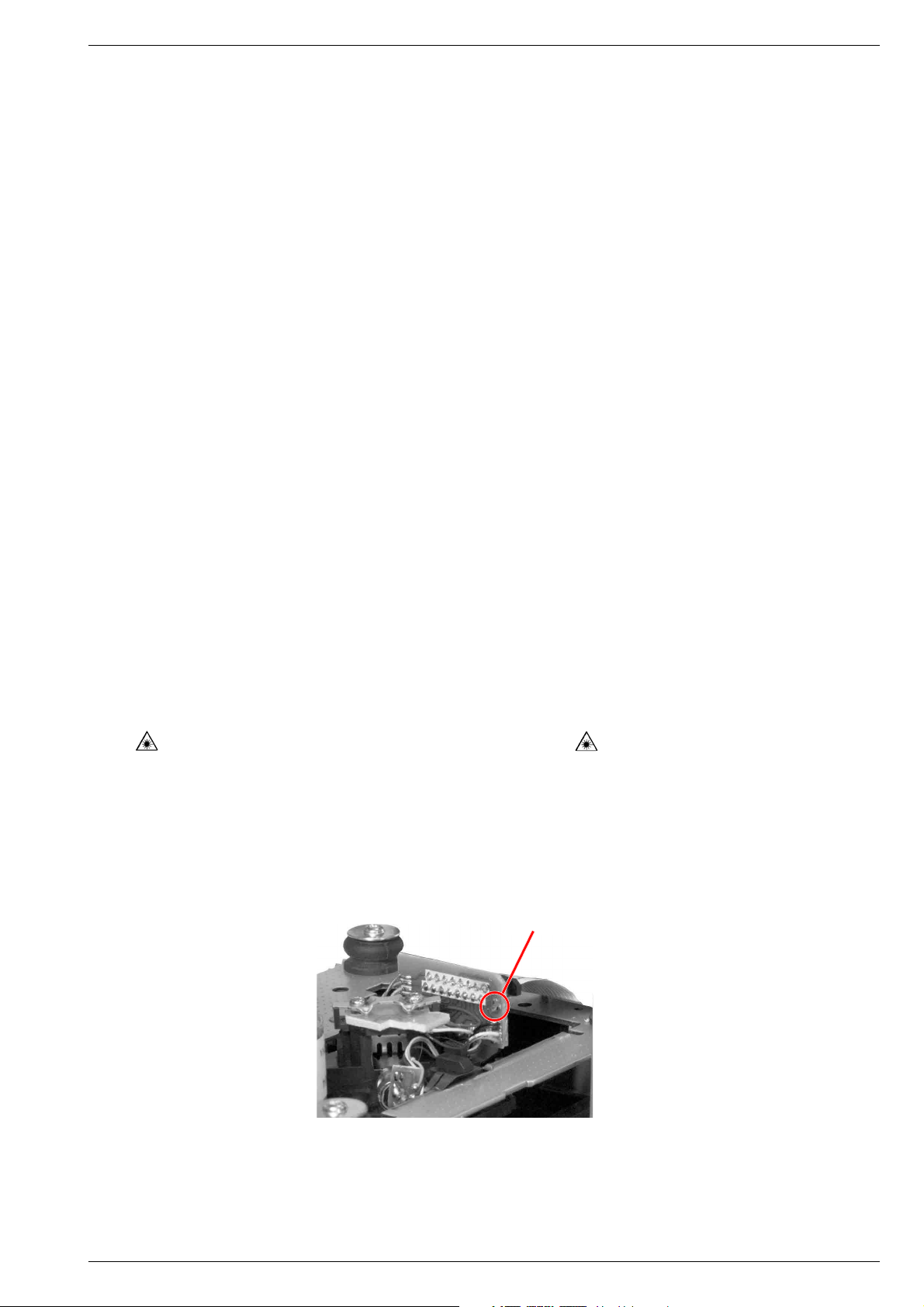
CD-Teil
Bei Ausbau der CD-Lasereinheit muss vor Abziehen der Steckverbindungen eine Schutzlötstelle auf der Leiterplatte der
Lasereinheit angebracht werden, um eine Zerstörung der Laserdiode durch statische Aufladung zu vermeiden.
Beim Einbau einer neuen Lasereinheit (CD-Laufwerk) muss
nach Einstecken der Steckverbinder die werkseitig angebrachte
Schutzlötstelle entfernt werden!
Disconnect the mains plug before opening the set.
Wiring
Before disconnecting any leads and especially the earth connecting
leads observe the way they are routed to the individual assemblies.
On completion of the repairs the leads must be laid out as originally
fitted at the factory to avoid later failures or disturbances.
CD Section
When removing the Laser pick-up, the Laser pick-up PCB must be
provided with a protective soldered joint before unplugging the
connectors to avoid damage to the Laser diode by static charges.
When inserting the new Laser pick-up (CD drive mechanism) the
soldered joint fitted at the factory must be removed after the
connectors are plugged in.
Schutzlötstelle
protective soldered joint
GRUNDIG Service 1 - 3
Page 4

Allgemeiner Teil / General Section Varixx UMS 4200
Technische Daten
Verstärkerteil
Ausgangsleistung:
Sinusleistung ...................................................................... 2 x 5W
Musikleistung ..................................................................... 2 x 8W
Empfangsteil
Empfangsbereiche:
FM ...................................................................... 87,5 ...108,0MHz
MW ....................................................................... 531 ... 1602kHz
Senderspeicher .......................................................... 20 FM, 20 MW
CD Teil
Frequenzgang ............................................................ 20Hz ... 20kHz
Geräuschspannungsabstand (wtd.) ....................................... > 70dB
Cassettenteil
Tonträger ....................... Compact-Cassette nach DIN 45516 (IECI)
Frequenzbereich ........................................................ 80Hz ... 10kHz
Spurlage ....................................................... Viertelspur international
Geräuschspannungsabstand (wtd.) ....................................... > 45dB
Gleichlaufschwankungen (WRMS) ....................................... ±0,25%
System
Spannungsversorgung:
Betriebsspannung ............................................................... 230V~
Netzfrequenz .................................................................... 50/60Hz
max. Leistungsaufnahme ....................................................... 45W
Leistungsaufnahme in Standby ............................................. < 5W
Leistungsaufnahme in Standby (Öko-Modus) ....................... < 1W
Abmessungen und Gewicht:
Abmessungen Gerät (B x H x T) .................... 145 x 208 x 209mm
Gewicht Gerät ..................................................................... 2,75kg
Abmessungen Lautsprecher (B x H x T) ........ 131 x 208 x 170mm
Gewicht pro Lautsprecher ................................................... 1,35kg
Technical Data
Amplifier Unit
Output:
Sine wave power ................................................................ 2 x 5W
Music power ....................................................................... 2 x 8W
Receiver Unit
Reception ranges:
FM ..................................................................... 87.5 ... 108.0MHz
AM ........................................................................ 531 ... 1602kHz
Station presets ............................................................ 20 FM, 20 AM
CD Unit
Frequency response .................................................. 20Hz ... 20kHz
Noise voltage ratio (wtd.) ....................................................... > 70dB
Cassette Unit
Sound recording medium ............................................ Compact tape
according to DIN 45516 (IECI)
Frequency range ........................................................ 80Hz ... 10kHz
Tracking position ...................................... International quarter-track
Noise voltage ratio (wtd.) ....................................................... > 45dB
Wow and flutter (WRMS) ...................................................... ±0.25%
System
Power supply:
Operating voltage ................................................................ 230V~
Mains frequency ............................................................... 50/60Hz
Max. power consumption ....................................................... 45W
Power consumption in stand-by mode .................................. < 5W
Power consumption in stand-by mode (eco mode) ............... < 1W
Dimensions and weight:
Device dimensions (W x H x L) ...................... 145 x 208 x 209mm
Device weight ......................................................................2.75kg
Loudspeaker dimensions (W x H x L) ............ 131 x 208 x 170mm
Weight per speaker ............................................................. 1.35kg
1 - 4 GRUNDIG Service
Page 5
Varixx UMS 4200 Allgemeiner Teil / General Section
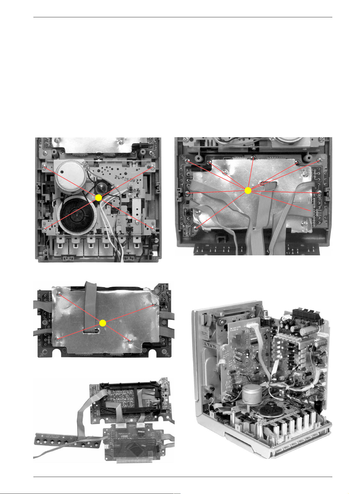
Ausbauhinweise
Bevor Sie Leitungen lösen, muss die Leitungsverlegung beachtet
werden. Nach erfolgter Reparatur ist es notwendig, die Leitungsführung in den werkseitigen Zustand zu versetzen.
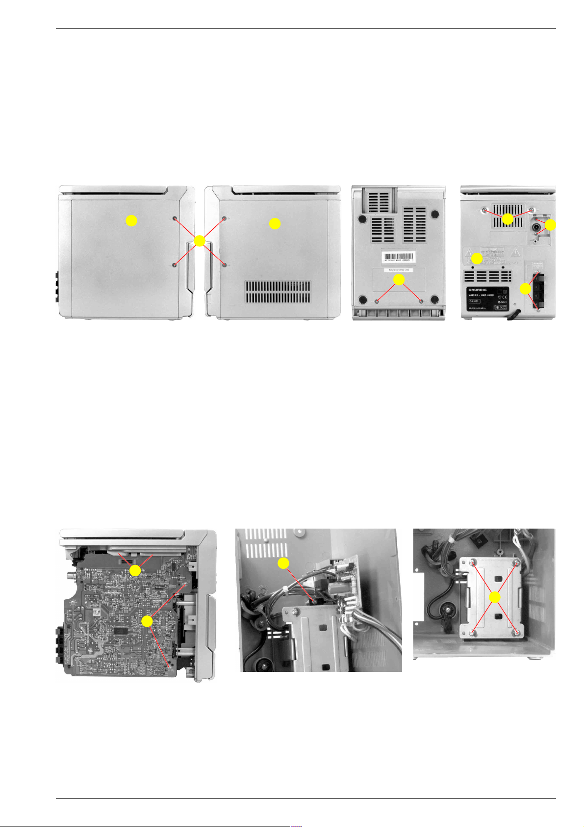
1. Gehäuse zerlegen
- 6 Schrauben A (Fig. 1, 2 und 3) herausdrehen.
- 4 Schrauben B (Fig. 4) herausdrehen.
- 2 Schrauben C (Fig. 4) herausdrehen.
- Rückwand D abziehen.
- Steckverbinder nach Bedarf abziehen.
D
D
A
Fig. 1 Fig. 2 Fig. 4
Disassembly Instructions
Before disconnecting any leads observe the way they are routed.
On completion of the repairs the leads must be laid out as
originally fitted at the factory.
1. Disassembling Cabinet
- Undo 6 screws A (Fig. 1, 2 and 3).
- Undo 4 screws B (Fig. 4).
- Undo 2 screws C (Fig. 4).
- Pull off the back panel C.
- Unplug connectors if necessary.
B
C
D
A
B
Fig. 3
2. Haupt-Platte ausbauen
- Gehäuse zerlegen (Pkt. 1).
- 2 Schrauben E (Fig. 5) herausdrehen.
- Haupt-Platte herausnehmen, Steckverbinder nach Bedarf abziehen.
- Beim Zusammenbau darauf achten, dass die Leiterplatte in den
Führungen F sitzt.
3. Netzteil ausbauen
- Gehäuse zerlegen.
- Schraube G (Fig. 6) herausdrehen.
- Netzteil-Platte herausziehen.
- 4 Schrauben H (Fig, 7) herausdrehen.
- Trafo herausnehmen.
F
G
E
2. Removing Main Board
- Disassemble cabinet (para 1).
- Undo 2 screws E (Fig. 5).
- Remove Main Board, unplug connectors if necessary.
- When reassembling take care that the board fits in the guides F.
3. Removing Power Supply
- Disassemble cabinet (para 1).
- Undo srew G (Fig. 6).
- Pull out power supply board.
- Undo 4 screws H (Fig. 7).
- Remove transformer.
H
Fig. 7
Fig. 5
GRUNDIG Service 1 - 5
Fig. 6
Page 6
Allgemeiner Teil / General Section Varixx UMS 4200
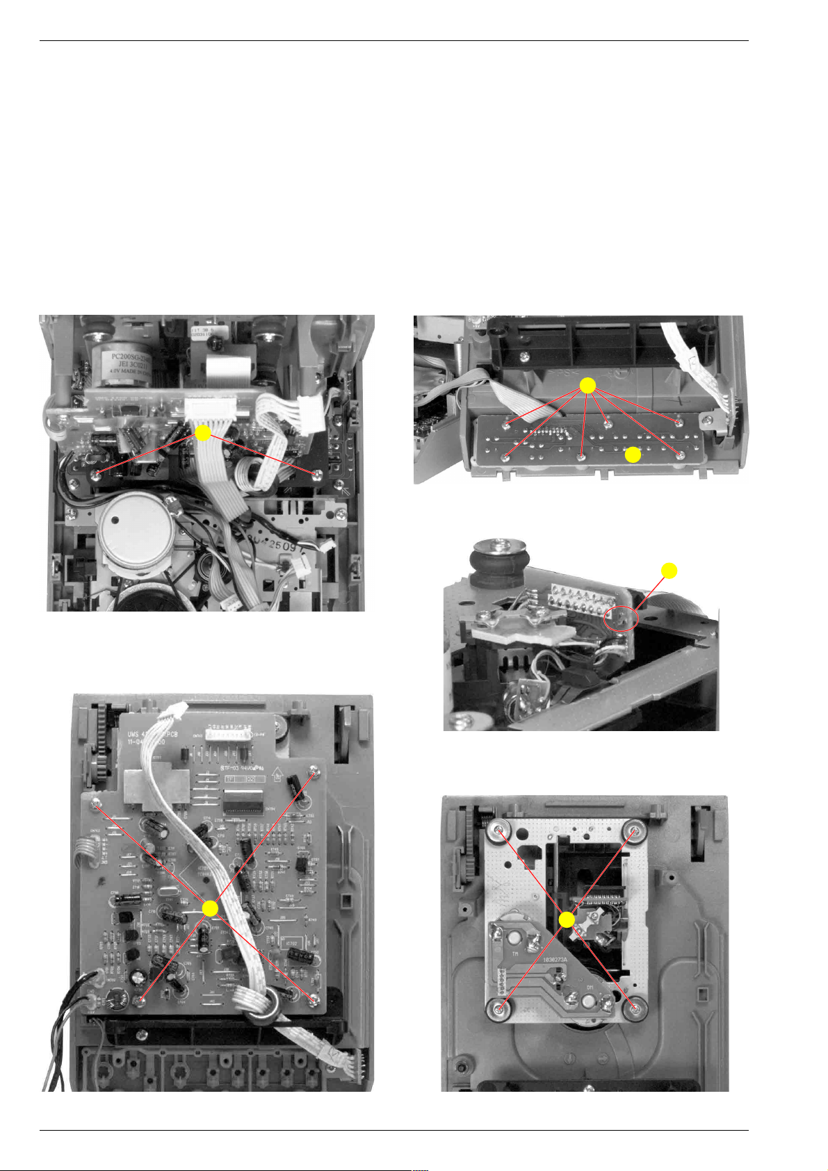
4. Oberteil mit CD-Laufwerk ausbauen
- Haupt-Platte ausbauen (Pkt. 2).
- 2 Schrauben J (Fig. 8) herausdrehen.
- Oberteil nach vorne hochheben.
- Stecker nach Bedarf abziehen.
- 6 Schrauben K (Fig. 9) herausdrehen und die Tasten-Platte L
abnehmen.
5. CD-Laufwerk ausbauen
- Oberteil abnehmen (Pkt. 4).
- 4 Schrauben M (Fig. 11) herausdrehen.
- CD-Platte abnehmen.
- Stecker nach Bedarf abziehen.
Achtung: Vor dem Abziehen der Flexprintleitung die Schutzlötstelle N (Fig. 10) zulöten! Die Laserdiode kann sonst durch
statische Aufladung zerstört werden.
- 4 Schrauben O (Fig. 12) herausdrehen und CD-Laufwerk herausnehmen.
J
4. Removing Top Cover with CD Drive
- Remove main board (para 2).
- Undo 2 screws J (Fig. 8).
- Lift top cover to the front.
- Unplug connectors if necessary.
- Undo 6 screws K (Fig. 9) and take out key board L.
5. Removing CD Drive
- Remove top cover (para 4).
- Undo 4 screws M (Fig. 11).
- Take off CD Board.
- Unplug connectors if necessary.
Caution: Before unplugging the flexprint close the protective
solder joint N (Fig. 10)! The Laser diode may otherwise be
destroyed by static electricity.
- Undo 4 screws O (Fig. 12) and take out CD Drive.
K
L
Fig. 8
Fig. 9
N
Fig. 10
M
J
Fig. 11 Fig. 12
1 - 6 GRUNDIG Service
Page 7
Varixx UMS 4200 Allgemeiner Teil / General Section
6. Cassetten-Laufwerk ausbauen
- Gehäuse zerlegen (Pkt. 1).
- 4 Schrauben P (Fig. 13) herausdrehen.
- Cassettenfach öffnen und Laufwerk herausnehmen.
- Stecker nach Bedarf abziehen.
7. Display- und Frontblatte ausbauen
- Oberteil abnehmen (Pkt. 4).
- 9 Schrauben Q (Fig. 14) herausdrehen.
- Display und Frontplatte herausnehmen.
- Stecker nach Bedarf abziehen.
- 4 Schrauben R (Fig. 15) herausschrauben.
- Die Front-Platte und die Display-Platte lassen sich jetzt auseinander
klappen (Fig. 16).
8. Kabelverlegung
- Nach erfolgter Reparatur ist es notwendig, die Leitungsführung
wieder in den werkseitigen Zustand zu versetzen um evtl. spätere
Ausfälle oder Störungen zu vermeiden (Fig. 17).
P
6. Removing Cassette Drive
- Disassemble cabinet (para 1).
- Undo 4 screws P (Fig. 13).
- Open cassette compartment and take out the cassette drive.
- Unplug connectors if necessary.
7. Removing the Display and the Front Board
- Remove top cover (para 4).
- Undo 9 screws Q (Fig. 14).
- Take out the front and the display board.
- Unplug connectors if necessary.
- Undo 4 screws R (Fig. 15).
- The front board and the display board can now be spread apart
(Fig. 16).
8. Wiring
- On completion of the repairs the leads must be laid out as originally
fitted at the factory to avoid later failures or disturbances (Fig. 17).
Q
Fig. 13
R
Fig. 15
Fig. 14
Fig. 16 Fig. 17
GRUNDIG Service 1 - 7
Page 8
1 - 8 GRUNDIG Service
6
AUF EINEN BLICK
______________________________________________________________________
STOP
■
Im CD-Betrieb:
beendet die Wiedergabe der CD;
löscht das Musikprogramm der CD.
5as6
Zum Einstellen der Uhrzeit;
SKIP/SEARCH zum Einstellen der Timer-Daten.
TUNING
Im Tuner-Betrieb:
längeres Drücken startet den Frequenzsuchlauf;
kurzes Drücken schaltet die Frequenz
schrittweise weiter oder startet den PTYSuchlauf.
Im CD-Betrieb:
Kurzes Drücken, wählt den vorherigen/
nächsten Titel;
längeres Drücken, sucht eine bestimmte
Passage.
PLAY/PAUSE
Im CD-Betrieb:
ı
II startet die Wiedergabe einer CD;
schaltet auf Wiedergabe-Pause.
OPEN/CLOSE Öffnet und schließt das CD-Fach.
8
AUF EINEN BLICK
______________________________________________________________________
TIMER ON/OFF Schaltet den Timer ein und aus.
ļ VOLUME Ļ Ändern die Lautstärke.
TIMER SET Zum Anzeigen der Uhrzeit;
aktiviert die Timer-Einstellung.
Tasten unter der Abdeckung:
Cassetten-Fach Öffnen mit
STOP
■
/ə.
RECORD
•
Startet die Aufnahme.
PLAY
4
Startet die Wiedergabe.
3
REWIND Spult die Cassette zum Bandanfang.
F.FWD
4
Spult die Cassette zum Bandende.
STOP
■
/əBeendet die Laufwerksfunktionen;
öffnet das Cassetten-Fach.
PAUSE II Schaltet auf Wiedergabe-Pause.
Die Anzeigen der HiFi-Anlage
STEREO
Stereo-Empfang im Tuner-FM-Betrieb..
=; Die gewählte Klangeinstellung ist
>< aktiviert.
UBS Die Bassanhebung ist aktiviert.
TIMER Der Ein- und Ausschalt-Timer ist aktiviert.
TIMER ON Leuchten während der Ein- und Ausschalt-
TIMER OFF Timer programmiert wird.
0000:00
00
CD SYNC
MHz
kHz
PROGRAM
TIMER ON OFF
RANDOM REPEAT ALL ONE
f
TOTAL REMAIN INTRO SLEEP
=
;><
STEREO
UBS
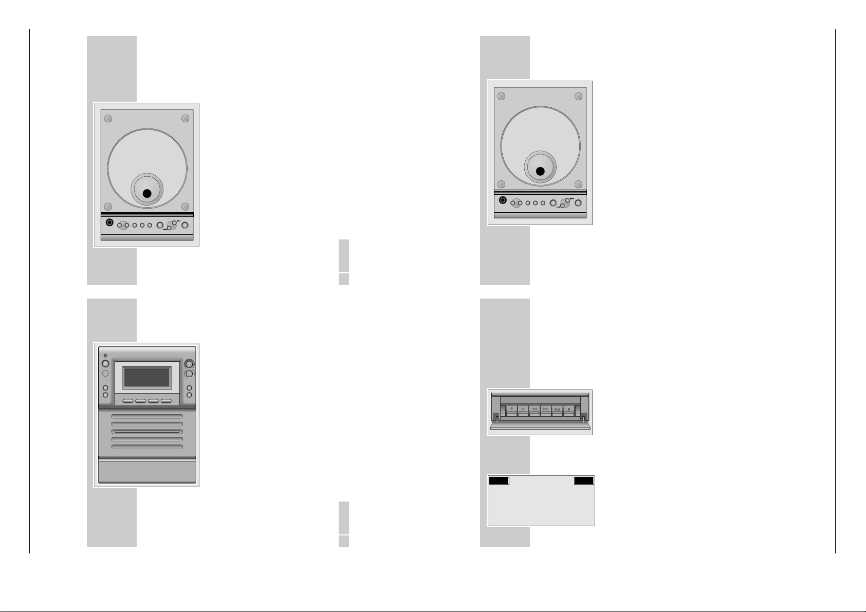
Bedienhinweise
Dieses Kapitel enthält Auszüge aus der Bedienungsanleitung. Weitergehende Informationen entnehmen Sie bitte der gerätespezifischen
Bedienungsanleitung, deren Materialnummer Sie in der entsprechenden Ersatzteilliste finden.
Allgemeiner Teil / General Section Varixx UMS 4200
AUF EINEN BLICK
Die Bedienelemente der HiFi-Anlage
Bedienelemente an der Oberseite
ʀ
arixx
ǵ
V
OPEN/CLOSE
P+P-
REPEAT
EQ/UBS
PRESET
PHONES
PROG
AUF EINEN BLICK
g/ECO
RDS/DISPLAY
PTY SEARCH
MULTICOLOUR LC-DISPLAY
CD TAPE COLOUR
BAND/TUNER
STEREO MICRO HIFI SYSTEM
ǵ
PLAY/PAUSE
SKIP/SEARCH/TUNING
STOP
VOLUME
TIME SET
TIMER ON/OFF
arixx
V
_____________________________________________________
PHONES Kopfhörerbuchse, zum Anschließen eines
P– PRESET P+ Im Tuner-Betrieb:
REPEAT Im CD-Betrieb:
PROG Zum Aktivieren und Speichern der Uhrzeit-
EQ/UBS Mehrmals drücken: wählt die Klangeinstel-
______________________________________________________________________
Stereo-Kopfhörers mit Klinkenstecker
(ø 3,5 mm).
Die Lautsprecher der HiFi-Anlage
werden automatisch abgeschaltet.
wählen gespeicherte Rundfunk-Programme;
wählen beim Speichern der RundfunkProgramme den Programmplatz.
einmal drücken, alle Titel der CD werden
wiederholt abgespielt;
zweimal drücken, der aktuelle Titel wird
wiederholt abgespielt.
und Timer-Einstellungen.
Im Tuner-Betrieb:
zum Speichern von Rundfunk-Programmen.
Im CD-Betrieb:
zum Speichern eines Musikprogrammes der
CD (bei Stopp).
lungen;
länger drücken: schaltet das Ultra-BassSystem ein und aus.
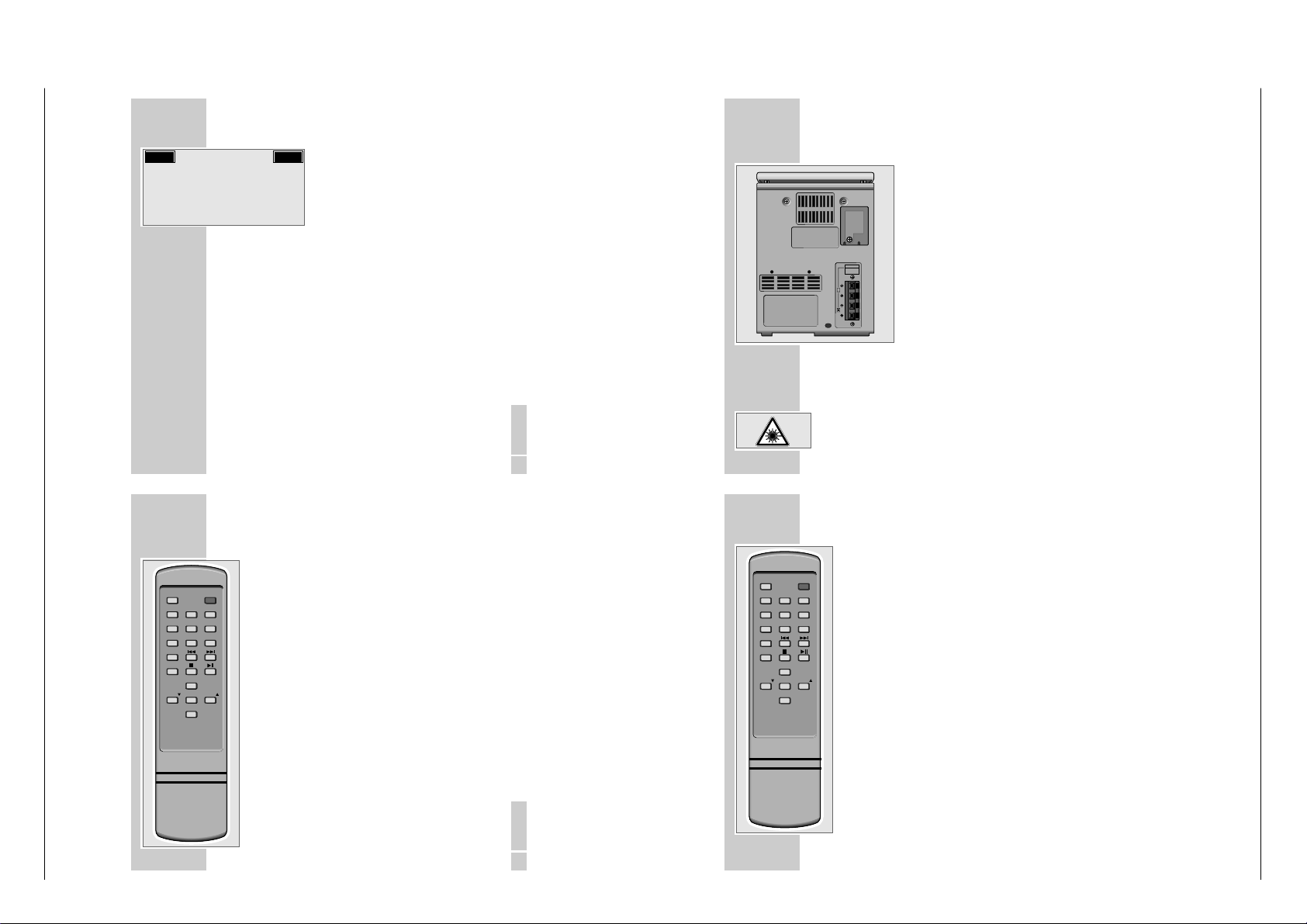
Bedienelemente an der Vorderseite
•
/ECO
Ǽ
O Infrarotauge für die Signale der Fern-
RDS/DISPLAY Im Tuner-Betrieb:
PTY SEARCH Im Tuner-Betrieb:
CD Wählt die Programmquelle CD.
TAPE Wählt die Programmquelle Tape.
TUNER/BAND Wählt die Programmquelle Tuner;
COLOUR Wählt die Farbe der Anzeigen-Beleuch-
Leuchtanzeige ( Öko-Modus).
Schaltet die HiFi-Anlage in Bereitschaft
(Stand-by) und aus Bereitschaft wieder
ein;
schaltet aus dem Demo-Programm ein;
länger drücken: schaltet die Hifi-Anlage
in den Öko-Modus.
bedienung.
zum Umschalten der Anzeige zwischen
Programmname, Programmtyp, Radiotext, Uhrzeit und Frequenz.
Im CD-Betrieb:
zum Umschalten der Anzeige zwischen
Spielzeit eines Titels, verbleibende
Spielzeit eines Titels und Gesamtspielzeit
der CD.
wählt die Funktion RDS-ProgrammtypenAnwahl.
wählt die Wellenbereiche »FM« oder
»MW«.
tung.
DEUTSCH
5
DEUTSCH
7
ʀ
arixx
ǵ
V
OPEN/CLOSE
P+P-
STOP
SKIP/SEARCH/TUNING
PLAY/PAUSE
REPEAT
EQ/UBS
PRESET
PHONES
PROG
Page 9
GRUNDIG Service 1 - 9
10
AUF EINEN BLICK
______________________________________________________________________
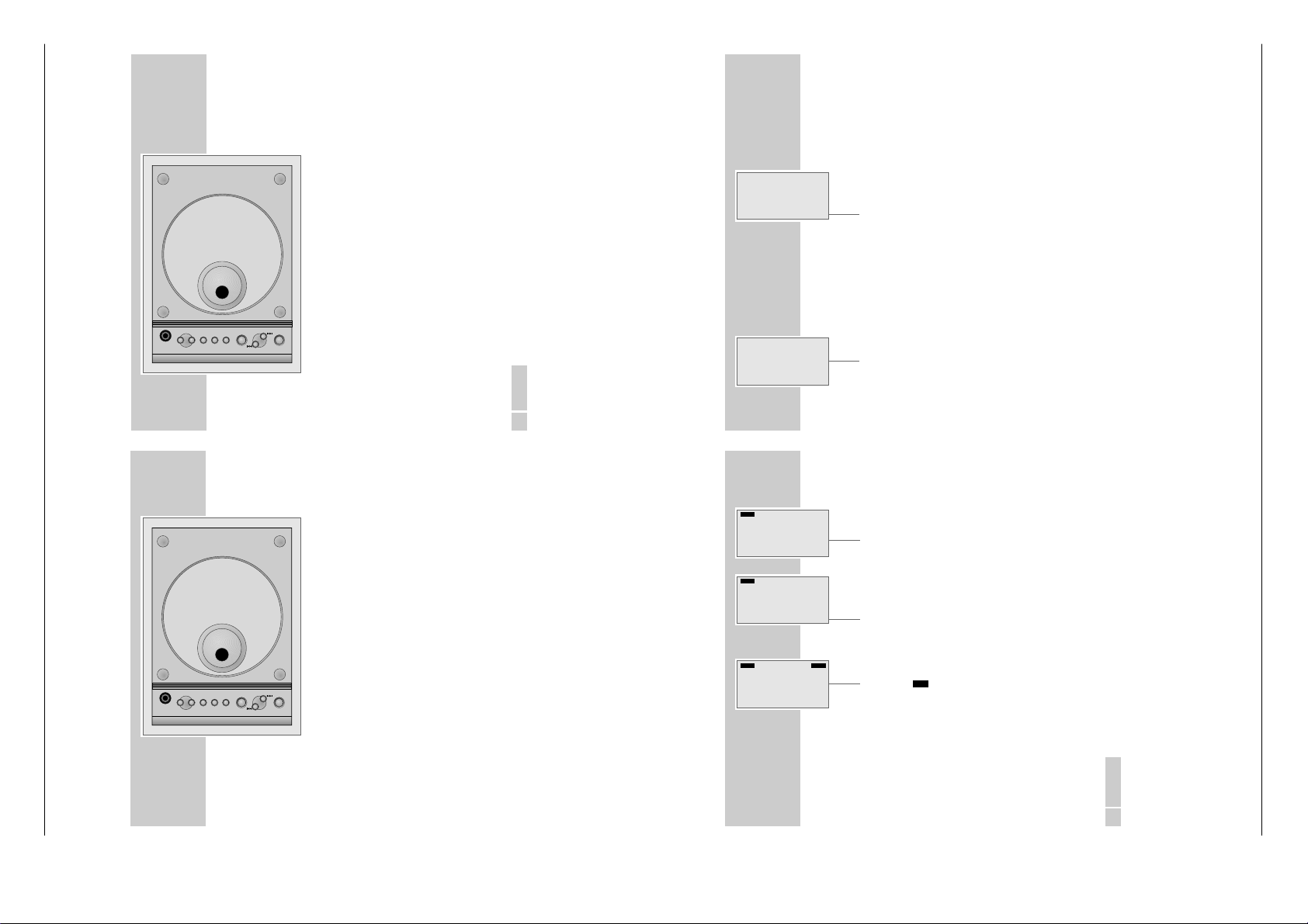
Die Rückseite der HiFi-Anlage
y
Wurfantenne für den FM (UKW) Empfang.
Für den MW-Empfang hat die HiFiAnlage eine eingebaute Antenne.
SPEAKERS
Lautsprecheranschlüsse für mitgelieferte
+
L +/– R+/–
Lautsprecherboxen.
L
= linker Kanal, R = rechter Kanal.
Ü Netzkabel.
Nur durch Ziehen des Netzsteckers ist
die HiFi-Anlage vom Stromnetz getrennt.
Allgemeine Hinweise für Geräte mit Laser
Der in das Gerät eingebaute Laser entspricht LASER CLASS 1 und ist wegen seines technischen Aufbaus eigensicher. So kann der maximal erlaubte Ausstrahlwert unter keinen Umständen überschritten werden.
Vorsicht:
Wenn andere als die hier spezifizierten Bedienungseinrichtungen benutzt
oder andere Verfahrensweisen ausgeführt werden, kann es zu gefährlicher
Strahlungsexposition kommen. Unsichtbare Laser-Strahlung tritt aus, wenn
das CD-Fach geöffnet oder die Sicherheitsverriegelung überbrückt wird.
Nicht dem Strahl aussetzen.
VOLUME
12
AUF EINEN BLICK
______________________________________________________________________
SLEEP Schaltet den Sleep-Timer ein und wieder aus.
INTRO Im CD-Betrieb:
zum kurzen Anspielen aller CD-Titel.
TUNING Im Tuner-Betrieb:
5as6
längeres Drücken startet den Frequenzsuchlauf;
kurzes Drücken schaltet die Frequenz schrittweise weiter.
SKIP/SEARCH Im CD-Betrieb:
5as6
kurzes Drücken wählt den nächsten oder vorherigen Titel;
längeres Drücken sucht eine bestimmte Passage.
REPEAT Im CD-Betrieb:
einmal drücken wiederholt alle Titel der CD;
zweimal drücken wiederholt den aktuellen Titel.
STOP
■
Im CD-Betrieb:
beendet die Wiedergabe;
löscht das Musikprogramm.
PLAY/PAUSE Im CD-Betrieb:
ı
II startet die Wiedergabe;
schaltet auf Wiedergabe-Pause.
P– PRESET P+ Im Tuner-Betrieb:
wählen gespeicherte Rundfunk-Programme;
wählen beim Speichern der Rundfunk-Programme den
Programmplatz.
ļ VOLUME Ļ Ändern die Lautstärke.
MUTE Schaltet die HiFi-Anlage stumm und wieder laut.
VOLUME
Varixx UMS 4200 Allgemeiner Teil / General Section
______________________________________________________________________
TOTAL Gesamtspieldauer einer CD wird angezeigt.
UBS
REMAIN Verbleibende Spielzeit eines Titels oder der
f
CD SYNC
MHz
kHz
RANDOM Wiedergabe der Titel einer CD in zufälliger
CD werden angezeigt (während der
Wiedergabe).
INTRO Funktion Intro ist aktiviert.
SLEEP Der Sleep-Timer ist aktiviert.
PROGRAM Leuchtet, wenn der Speicherplatz eines
Rundfunk-Programmes angezeigt wird;
blinkt, wenn ein Musikprogramm gespeichert
wird;
zeigt die Wiedergabe eines
Musikprogrammes an.
Reihenfolge .
SPEAKERS
IMPEDANCE
4Ω
L
STEREO
=
TIMER ON OFF
PROGRAM
RANDOM REPEAT ALL ONE
0000:00
00
AUF EINEN BLICK
;><
TOTAL REMAIN INTRO SLEEP
REPEAT ALL Alle Titel einer CD werden wiederholt abgespielt.
REPEAT ONE Der aktuelle Titel wird wiederholt abgespielt.
f
00 0000:00 Im CD-Betrieb: Nummer des Titels, die
Ein RDS-Programm wird empfangen.
Gesamtspielzeit, die aktuelle Spielzeit.
Im Tuner-Betrieb: Programmplatz eines Rundfunk-
Programmes, Wellenbereich, Frequenz, RDSFunktionen.
Uhrzeit.
CD SYNC Synchron-Aufnahme von einer CD.
SYNC Die RDS-Zeitsynchronisation ist aktiv.
MHz Frequenzanzeige (FM).
kHz Frequenzanzeige (MW).
AUF EINEN BLICK
EQ/UBS
BAND/
TAPE CD
TUNER
MONO/
BEAT CUT
STEREO
RANDOM
DEMO
INTRO
REPEAT
P+
MUTEVOLUME
P–
ǵ
Die Fernbedienung
Ǽ
g/ECO
RDS/
DISPLAY
SLEEP
EQ/UBS Mehrmals drücken: wählt die Klangeinstellungen;
TUNER/BAND Wählt die Programmquelle Tuner; wählt die Wellenbereiche
TAPE Wählt die Programmquelle Tape.
CD Wählt die Programmquelle CD.
MONO/STEREO Im Tuner-Betrieb:
BEAT CUT Im Tuner-MW-Betrieb:
RDS/DISPLAY Im Tuner-Betrieb:
RANDOM Im CD-Betrieb:
DEMO Zum Ein- und Ausschalten des Demo-Programmes in
______________________________________________________________________
/ECO
Schaltet die HiFi-Anlage in Bereitschaft (Stand-by) und aus
Bereitschaft wieder ein; schaltet aus dem Demo-Programm
ein;
länger drücken: schaltet die HiFi-Anlage in den Öko-Modus.
länger drücken: schaltet das Ultra-Bass-System ein und aus.
»FM« oder »MW«.
schaltet zwischen Mono- und Stereo-Empfang um.
unterdrückt Pfeifstörungen während der Aufnahme eines
MW-Programmes.
zum Umschalten der Anzeige zwischen Programmname,
Programmtyp, Radiotext, Uhrzeit und Frequenz.
Im CD-Betrieb:
zum Umschalten der Anzeige zwischen Spielzeit eines Titels
und verbleibender Spielzeit eines Titels oder der CD.
zur Wiedergabe von Titeln in zufälliger Reihenfolge.
Bereitschaft (Stand-by) (zeigt nacheinander alle Funktionen
der HiFi-Anlage an).
DEUTSCH
9
DEUTSCH
11
EQ/UBS
BAND/
TAPE CD
TUNER
MONO/
BEAT CUT
STEREO
RANDOM
DEMO
INTRO
REPEAT
MUTEVOLUME
ǵ
g/ECO
RDS/
DISPLAY
SLEEP
P+
P–
Page 10
1 - 10 GRUNDIG Service
18
ALLGEMEINE FUNKTIONEN
___________________________
Ein- und Ausschalten
1
HiFi-Anlage mit
»Ǽ/ECO«
aus Bereitschaft (Stand-by) einschalten.
– Die zuletzt aktive Programmquelle wird automatisch gewählt.
Hinweis:
Zum Einschalten können auch folgende Tasten am Gerät oder an der Fernbedienung verwendet werden:
»TUNER/BAND« – Tuner-Betrieb;
»CD« – CD-Betrieb;
»TAPE« – Cassetten-Betrieb.
2
Gerät mit
»Ǽ/ECO«
in Bereitschaft (Stand-by) schalten.
– Anzeige: die aktuelle Uhrzeit.
Hinweis:
Nur durch Ziehen des Netzssteckers ist die HiFi-Anlage vom Stromnetz
getrennt. Uhrzeit und Timereinstellungen gehen dabei verloren
In den Öko-Modus schalten
Mit dieser Einstellung verringern Sie die Leistungsaufnahme der HiFi-Anlage in
Bereitschaft (Stand-by).
1 »
Ǽ
/ECO«
länger (ca. 1 Sekunde) drücken.
– Die rote Anzeige leuchtet, die Uhrzeitanzeige erlischt.
Programmquelle wählen
1
Gewünschte Programmquelle
mit »TUNER«, »CD« oder »TAPE« wählen
.
– Anzeige : Wellenbereich und Frequenz oder Programmname, Gesamtzahl
der CD-Titel und Gesamtspielzeit oder »TAPE«.
Lautstärke ändern
1
Lautstärke
mit »ļVOLUME Ļ «ändern.
– Anzeige: kurz »VOL « und der gewählte Wert (»MIN«, »I« bis »39«,
danach »MAX«).
I5:20
TAPE
DEUTSCH
19
ALLGEMEINE FUNKTIONEN
____________________________________________________
Stummschaltung (Mute)
Mit dieser Funktion schalten Sie die Hifi-Anlage „stumm”.
1 Stummschaltung mit » MUTE« an der Fernbedienung ein- oder ausschalten.
– Anzeige: »MUTING« blinkt.
Klangeinstellung
Sie können zwischen fünf verschiedenen Klangeinstellungen (»FLAT«, » POP«,
»CLASSIC«, » ROCK« und »JAZZ«) entsprechend der jeweiligen Musikart
wählen. Grundeinstellung ist »FLAT«.
1 Gewünschte Klangeinstellung mit »EQ/UBS« wählen.
– Anzeige: kurz »FLAT«, »POP«, » CLASSIC«, » ROCK« oder »JAZZ«, dauer-
haft »=«, » ;«, »>« oder » <«.
Bässe verstärken
1 Zum Ein- oder Ausschalten der Bassanhebung » EQ/UBS« länger (ca. 1
Sekunde) drücken.
– Anzeige: »« und kurz »UBS ON«.
Uhrzeit ein- und ausblenden
1 Zum Ein- und Ausblenden der Uhrzeit in eingeschaltetem Zustand » TIMER
SET« am Gerät drücken.
Demo-Programm ein- und ausschalten
1 Zum Einschalten des Demo-Programmes in Bereitschaft (Stand-by)
»DEMO« an der Fernbedienung drücken.
2 Zum Ausschalten des Demo-Programmes » DEMO« an der Fernbedienung,
»
Ǽ
/ECO« oder jede andere Funktionstaste drücken.
UBS
MUTING
PROGRAM
STEREO
CLASSIC
PROGRAM
;
STEREO
UBS ON
SYNC
MHz
f
U B SSTEREO
Operating Hints
This chapter contains excerpts from the operating instructions. For further particulars please refer to the appropriate user instructions the part number
of which is indicated in the relevant spare parts list.
Allgemeiner Teil / General Section Varixx UMS 4200
OVERVIEW
The HiFi system controls
Controls on the top
ʀ
arixx
ǵ
V
OPEN/CLOSE
P+P-
REPEAT
EQ/UBS
PRESET
PHONES
PROG
OVERVIEW
ʀ
ǵ
P+P-
REPEAT
EQ/UBS
PRESET
PROG
PHONES
6
PLAY/PAUSE
SKIP/SEARCH/TUNING
STOP
__________________________________________________________________________________
arixx
V
OPEN/CLOSE
PLAY/PAUSE
SKIP/SEARCH/TUNING
STOP
_______________________________________________________________________
PHONES Headphone jack for connecting a stereo
P– PRESET P+ In tuner mode:
REPEAT In CD mode:
PROG For activating and saving the clock and
EQ/UBS Press repeatedly: selects the sound settings;
STOP
5as6
SKIP/SEARCH for setting the timer data.
TUNING
PLAY/PAUSE
ı
OPEN/CLOSE Opens and closes the CD compartment.
headphone set with a jack plug
(ø 3.5 mm).
The loudspeakers of the HiFi system are
automatically switched off.
select stored radio stations;
select the preset position when storing radio
stations.
pressing once repeats all the tracks on a CD;
pressing twice repeats the current track.
timer settings.
In tuner mode:
for manually storing radio stations.
In CD mode:
for storing a track memory for the CD
(in Stop mode).
press once and hold down: switches the
ultra-bass system on and off.
■
In CD mode:
ends CD playback;
deletes the track memory of the CD.
For setting the time;
In tuner mode:
holding down starts the station search;
pressing briefly changes the frequency in
small steps or starts the PTY search.
In CD mode:
pressing briefly selects the previous/
next track;
holding down searches for a particular
passage.
In CD mode:
II starts CD playback;
pauses playback.
ENGLISH
5
Page 11

GRUNDIG Service 1 - 11
8
OVERVIEW
__________________________________________________________________________________
TIMER ON/OFF Switches the timer on and off.
ļ VOLUME Ļ Adjusts the volume.
TIMER SET Displays the time;
activates the timer setting.
Buttons under the cover:
Tape
compartment Open by pressing
STOP
■
/ə.
RECORD
•
Starts recording.
PLAY
4
Starts playback.
3
REWIND Rewinds the tape to the beginning.
F.FWD
4
Fast forwards the tape to the end.
STOP
■
/əEnds the drive functions;
opens the tape compartment.
PAUSE II Switches to playback pause.
The HiFi display
STEREO
Stereo reception in tuner FM mode.
=; The selected sound setting is activated.
><
UBS The bass boost is activated.
TIMER The ON/OFF timer is activated.
TIMER ON Illuminate while the ON/OFF timer
TIMER OFF is being programmed.
0000:00
00
CD SYNC
MHz
kHz
PROGRAM
TIMER ON OFF
RANDOM REPEAT ALL ONE
f
TOTAL REMAIN INTRO SLEEP
=
;><
STEREO
UBS
10
OVERVIEW
__________________________________________________________________________________
The back of the HiFi system
y
Wire antenna for FM (UKW) reception.
The HiFi system has a built-in antenna for
MW reception.
SPEAKERS
Loudspeaker connections for the supplied
L +/– R +/–
loudspeakers.
L
= left channel, R = right channel.
Ü Mains cable.
The only way to isolate the HiFi system
from the mains supply is to pull the plug
out.
General instructions for laser devices
The laser installed in the device conforms to LASER CLASS 1 and is designed to
ensure that the maximum permissible emission value cannot be exceeded under
any circumstances.
Caution:
If operating devices or methods other than those specified here are employed, it may lead to dangerous exposure to emissions. Invisible laser radiation
is emitted if the CD compartment is opened or the safety locking mechanism
is shorted. Do not expose yourself to this radiation.
Varixx UMS 4200 Allgemeiner Teil / General Section
OVERVIEW
__________________________________________________________________________________
Controls on the front
•
/ECO
Ǽ
g/ECO
RDS/DISPLAY
PTY SEARCH
MULTICOLOUR LC-DISPLAY
CD TAPE COLOUR
BAND/TUNER
STEREO MICRO HIFI SYSTEM
ǵ
OVERVIEW
STEREO
=
;><
TIMER ON OFF
PROGRAM
00
TOTAL REMAIN INTRO SLEEP
RANDOM REPEAT ALL ONE
0000:00
VOLUME
TIME SET
O Infrared receiver for remote control
TIMER ON/OFF
RDS/DISPLAY In tuner mode:
PTY SEARCH In tuner mode:
arixx
V
f
CD SYNC
CD Selects the ”CD” input source.
TAPE Selects the ”Tape” input source.
TUNER/BAND Selects the ”Tuner” input source;
COLOUR Selects the colour of the display illumina-
__________________________________________________________________________________
TOTAL The total playing time of a CD is displayed.
UBS
REMAIN Displays the playback time remaining on a
track or on the CD (during playback).
INTRO The Intro function is activated.
SLEEP The sleep timer is activated.
MHz
PROGRAM Illuminates when the storage position of a
kHz
RANDOM Playback of the tracks on a CD in random order.
REPEAT ALL All the tracks on a CD are repeated.
REPEAT ONE The current track is repeated.
f
00 0000:00 In CD mode: track number, total playing time, current
CD SYNC Synchro recording from a CD.
SYNC The RDS time synchronisation is activated.
MHz Frequency display (FM).
kHz Frequency display (MW).
radio station is displayed;
flashes when a radio station is stored;
indicates playback of a track memory.
An RDS station is being received.
playing time.
In tuner mode: preset position of a radio station,
frequency band, frequency, RDS functions.
Time.
LED (power-saving mode).
Switches the HiFi system to and from
stand-by mode;
switches on from demo mode;
pressing and holding down: switches the
HiFi system to power-saving mode.
signals.
switches the display between the station
name, station type, radio text, time and
frequency.
In CD mode:
switches the display between the playing
time of a track, the remaining playing
time of a track and the total playing time
of the CD.
selects the function ”RDS station types
selection”.
selects the frequency band – »FM « or
»MW«.
tion.
ENGLISH
7
ENGLISH
9
SPEAKERS
IMPEDANCE
4Ω
L
Page 12

1 - 12 GRUNDIG Service
VOLUME
12
OVERVIEW
__________________________________________________________________________________
SLEEP Switches the sleep timer on and off.
INTRO In CD mode:
for a brief sample playback of each track.
TUNING In tuner mode:
5as6
hold down to start the station search;
press briefly to change the frequency in small steps.
SKIP/SEARCH In CD mode:
5as6
pressing briefly selects the next or previous track;
hold down to search for a particular passage.
REPEAT In CD mode:
pressing once repeats all the tracks on the CD;
pressing twice repeats the current track.
STOP
■
In CD mode:
ends CD playback;
deletes the track memory.
PLAY/PAUSE In CD mode:
ı
II starts playback;
pauses playback.
P– PRESET P+ In tuner mode:
select stored radio stations;
select the preset position when storing radio stations.
ļ VOLUME Ļ Adjust the volume.
MUTE Switches the system to and from mute mode.
VOLUME
ENGLISH
19
GENERAL FUNCTIONS
______________________________________________________________
Muting
This function enables you to ”silence” the device.
1 Press » MUTE« on the remote control to switch the sound on or off.
– Display: »MUTING« flashes.
Sound settings
You can select from among five different sound settings (»FLAT«, »POP«,
»CLASSIC«, »ROCK« and » JAZZ«), depending on the type of music you are
listening to. The basic setting is »FLAT«.
1 Select the sound setting by pressing »EQ/UBS«.
– Display: briefly, »FLAT«, »POP«, » CLASSIC«, »ROCK« or »JAZZ«, continuously
»=«, »;«, » >« or »<«.
Boosting the bass
1 To switch the bass boost on and off, press
press and briefly hold down (ca. 1
second)
»EQ/UBS«.
– Display: »« and, briefly, »UBS ON«.
Displaying/concealing the time
1 To display or conceal the time, press »TIMER SET« on the device while it is
activated.
Switching the demo program on and off
1 To activate the demo program, press »DEMO« on the remote control while
the device is in stand-by mode.
2 To deactivate the demo program, press »DEMO« on the remote control or
press »
Ǽ
/ECO«. Any other function button on the device or on the remote
control can also be used to switch off the demo program.
UBS
MUTING
PROGRAM
STEREO
CLASSIC
PROGRAM
;
STEREO
UBS ON
SYNC
MHz
f
U B SSTEREO
Allgemeiner Teil / General Section Varixx UMS 4200
OVERVIEW
EQ/UBS
g/ECO
BAND/
TAPE CD
TUNER
MONO/
RDS/
BEAT CUT
STEREO
DISPLAY
RANDOM
DEMO
SLEEP
INTRO
REPEAT
P+
MUTEVOLUME
P–
ǵ
GENERAL FUNCTIONS
TAPE
18
I5:20
__________________________________________________________________________________
The remote control
/ECO
Ǽ
EQ/UBS Press repeatedly: selects the sound settings;
TUNER/BAND Selects the tuner input source; selects the frequency bands
TAPE Selects the tape input source.
CD Selects the CD input source.
MONO/STEREO In tuner mode:
BEAT CUT In Tuner mode (MW):
RDS/DISPLAY In tuner mode:
RANDOM In CD mode:
DEMO For switching the demo program on and off in stand-by
Switching on and off
1
2
Switching to power-saving mode
This setting enables you to reduce the power consumed by the HiFi system in
stand-by mode.
1
Selecting the input source
1
Adjusting the volume
1
Switches the HiFi system to and from stand-by mode; switches
on from demo mode;
extended pressing: switches the HiFi system to power-saving
mode.
press once and hold down: switches the ultra-bass system on
and off.
»FM« and »MW«.
switches between mono and stereo reception.
suppresses audio interference when the recording from a
MW station.
switches the display between the station name, station type,
radio text, time and frequency.
In CD mode:
switches the display between the playing time of a track and
the remaining playing time for a track or for the CD.
for playing tracks in random order.
mode (displays all the HiFi system’s functions in succession).
_________________________________________
Switch on the HiFi system out of stand-by mode by pressing
– The last input source used is automatically selected.
Note:
The following buttons on the device can also be used to switch on the stereo
system:
»TUNER/BAND« – tuner-mode;
»CD« – CD mode;
»TAPE« – tape mode.
Press
»Ǽ/ECO«
– Display: the current time.
Note:
The only way to isolate the HiFi system from the mains supply is to pull the
plug. This causes time and timer settings to be deleted.
Press and briefly hold down (ca. 1 second)
– The red indicator light is illuminated, the time display disappears.
Select the program source
– Display: frequency band and frequency or station name, total number of
Use
– Display: briefly, »VOL «and the selected value (»MIN«, »I« to »39«, follo-
to switch the device to stand-by mode.
»Ǽ/ECO«
by pressing »TUNER«, »CD« or »TAPE«
CD tracks and total playing time or »TAPE«.
»ļVOLUME Ļ « to adjust the volume.
wed by »MAX«).
.
»Ǽ/ECO«
EQ/UBS
g/ECO
BAND/
TAPE CD
TUNER
MONO/
RDS/
BEAT CUT
STEREO
DISPLAY
RANDOM
DEMO
SLEEP
INTRO
REPEAT
P+
MUTEVOLUME
P–
ǵ
ENGLISH
11
.
.
Page 13

Varixx UMS 4200 Abgleichvorschriften / Adjustment Procedures
Abgleichvorschriften
Tuner
Messgeräte: Mess-Sender, Oszilloskop, Digital-Voltmeter
Abgleich Vorbereitung Abgleichvorgang
1. AM-Oszillator
AM;
Digital-Voltmeter an Messpunkt TP1.
2. AM-ZF
AM;
Mess-Sender 450kHz über Loop-Antenne ankoppeln;
3. AM-Vorkreis
Ue > 70dBµV; f
Oszilloskop an Lautsprecher-Ausgang.
AM;
= 1kHz; m = 30%;
mod
Mess-Sender über Loop-Antenne ankoppeln;
4. FM-Oszillator
Ue > 40dBµV; f
Oszilloskop an Lautsprecher-Ausgang.
FM;
= 1kHz; m = 30%;
mod
Digital-Voltmeter an Messpunkt TP2.
5. FM-Vorkreise
FM;
Mess-Sender an FM-Antennen-Eingang;
Ue = 20dBµV; f
Oszilloskop an Lautsprecher-Ausgang.
= 1kHz; Hub = 75kHz;
mod
Cassette
Messgeräte: Oszilloskop, Frequenzzähler, Test-Cassette 3150Hz/10kHz (z.B. 448A)
Mit T202 bei 1602kHz auf 7,5V ± 0,5V abgleichen.
Mit T201 auf NF-Maximum abgleichen.
Wechselweise mit MW COIL (verschieben) bei 558kHz
und mit VC201 bei 1440kHz auf NF-Maximum abgleichen.
Mit L203 (verbiegen) bei 108,0MHz auf 7,5V ± 0,5V abgleichen.
Wechselweise mit L204 (verbiegen) bei 88,0MHz und mit
VC202 bei 106,0MHz auf NF-Maximum abgleichen.
L208 (verbiegen) wechselweise bei 88,0MHz und bei
108,0MHz auf NF-Maximum abgleichen (ausmitteln).
Abgleich Vorbereitung Abgleichvorgang
1. Bandgeschwindigkeit
2. Azimut
Frequenzzähler an Lautsprecher.
Test-Cassette (3150Hz-Teil) abspielen.
Oszilloskop an Lautsprecher.
Test-Cassette (10kHz-Teil) abspielen.
Mit Motorpoti auf 3150Hz ± 10Hz
abgleichen.
Mit Kopfschraube A auf maximalen
und gleichen Pegel in beiden
Kanälen einstellen.
3. Löschoszillator
Frequenzzähler an CN302(-1).
Mit T360 auf 60kHz ± 100Hz abgleichen.
Aufnahme starten.
Motorpoti
A
GRUNDIG Service 2 - 1
Page 14

Abgleichvorschriften / Adjustment Procedures Varixx UMS 4200
Adjustment Procedures
Tuner
Test equipment: Signal Generator, Oscilloscope, Digital Voltmeter
Adjustment Preparation Adjustment Procedure
1. AM Oscillator
AM;
Adjust with T202 at 1602kHz for 7.5V ± 0.5V.
Digital Voltmeter to Testpoint TP1.
2. AM IF
AM;
Adjust with T201 for AF Maximum.
Couple Signal Generator 450kHz via Loop Antenna;
3. AM Pre Stage
4. FM Oscillator
Ue > 70dBµV; f
Oszilloscope to Loudspeaker Output.
AM;
Couple Signal Generator via Loop Antenna;
Ue > 40dBµV; f
Oszilloscope to Loudspeaker Output.
FM;
= 1kHz; m = 30%;
mod
= 1kHz; m = 30%;
mod
Adjust alternating with MW COIL (move) at 558kHz and
with VC201 at 1440kHz for AF Maximum.
Adjust with L203 (bend) at 108.0MHz for 7.5V ± 0.5V.
Digital Voltmeter to Testpoint TP1.
5. FM Pre Stage
FM;
Signal Generator to FM Aerial Input;
Ue = 20dBµV; f
Oszilloscope to Loudspeaker Output.
= 1kHz; deviation = 75kHz;
mod
Adjust alternating with L204 (bend) at 88.0MHz and with
VC202 at 106.0MHz for AF Maximum.
Adjust L208 (bend) alternating at 88.0MHz and at
108.0MHz for AF Maximum (averaging).
Tape Deck
Test equipment: Oscilloscope, Frequency Counter, Test Cassette 3150Hz/10kHz (e.g. 448A)
Adjustment Preparation Adjustment Procedure
1. Tape Speed
Frequency Counter to Loudspeaker Output.
Adjust Motorpoti for 3150Hz ± 10Hz.
Play Test Cassette (3150Hz part).
2. Azimuth
3. Bias Frequency
Oszilloscope to Loudspeaker Output.
Play Test Cassette (10kHz part).
Frequency Counter to CN302(-1).
With Head screw A adjust for maximal
and equal level in both channels.
Adjust with T360 for 60kHz ± 100Hz.
Start recording.
Motorpoti
A
2 - 2 GRUNDIG Service
Page 15

Varixx UMS 4200 Abgleichvorschriften / Adjustment Procedures
Abgleichlageplan / Alignment Layout
GRUNDIG Service 2 - 3
Page 16

Schaltpläne und Platinenabbbildungen / Circuit Diagrams and Layout of the PCBs Varixx UMS 4200
Schaltpläne und Platinenabbildungen / Circuit Diagrams and Layout of the PCBs
Blockschaltbild / Block Diagram
3 - 1 GRUNDIG Service
Page 17

Varixx UMS 4200 Schaltpläne und Platinenabbildungen / Circuit Diagrams and Layout of the PCBs Varixx UMS 4200 Schaltpläne und Platinenabbildungen / Circuit Diagrams and Layout of the PCBs
Verdrahtungsplan / Wiring Diagram
GRUNDIG Service GRUNDIG Service
3 - 33 - 2
Page 18

Schaltpläne und Platinenabbildungen / Circuit Diagrams and Layout of the PCBs Varixx UMS 4200 Schaltpläne und Platinenabbildungen / Circuit Diagrams and Layout of the PCBs Varixx UMS 4200
Teilschaltplan Tuner / Circuit Diagram section Tuner
S./p. 3-16
S./p. 3-10
S./p. 3-17
S./p. 3-16
to CN103
S./p. 3-12
S./p. 3-10
S./p. 3-9
GRUNDIG Service GRUNDIG Service
3 - 53 - 4
Page 19

Varixx UMS 4200 Schaltpläne und Platinenabbildungen / Circuit Diagrams and Layout of the PCBs Varixx UMS 4200 Schaltpläne und Platinenabbildungen / Circuit Diagrams and Layout of the PCBs
Teilschaltplan CD / Circuit Diagram section CD
to CN851
S./p. 3-10
to CN104
S./p. 3-13
to CN602
S./p. 3-9
S./p. 3-16
S./p. 3-17
GRUNDIG Service GRUNDIG Service
3 - 73 - 6
Page 20

Schaltpläne und Platinenabbildungen / Circuit Diagrams and Layout of the PCBs Varixx UMS 4200 Schaltpläne und Platinenabbildungen / Circuit Diagrams and Layout of the PCBs Varixx UMS 4200
Teilschaltplan Cassette / Circuit Diagram section Cassette
to CN702
S./p. 3-6
S./p. 3-16
S./p. 3-16
to CN105
S./p. 3-12
S./p. 3-5
S./p. 3-10
GRUNDIG Service GRUNDIG Service
3 - 93 - 8
Page 21

Varixx UMS 4200 Schaltpläne und Platinenabbildungen / Circuit Diagrams and Layout of the PCBs Varixx UMS 4200 Schaltpläne und Platinenabbildungen / Circuit Diagrams and Layout of the PCBs
Teilschaltplan NF-Teil, Netzteil / Circuit Diagram section AF Part, Power Supply
to CN701
S./p. 3-6
S./p. 3-9
S./p. 3-5
Netz/Mains
230V~
50/60Hz
to CN102
S./p. 3-13
GRUNDIG Service GRUNDIG Service
3 - 113 - 10
Page 22

Schaltpläne und Platinenabbildungen / Circuit Diagrams and Layout of the PCBs Varixx UMS 4200 Schaltpläne und Platinenabbildungen / Circuit Diagrams and Layout of the PCBs Varixx UMS 4200
Teilschaltplan CPU, Display / Circuit Diagram section CPU, Display
to CON4
S./p. 3-14
to CN260
S./p. 3-5
to CN705
S./p. 3-6
to CN6
S./p. 3-14
to CN601
S./p. 3-9
to CN850
S./p. 3-10
GRUNDIG Service GRUNDIG Service
3 - 133 - 12
Page 23

Varixx UMS 4200 Schaltpläne und Platinenabbildungen / Circuit Diagrams and Layout of the PCBs Varixx UMS 4200 Schaltpläne und Platinenabbildungen / Circuit Diagrams and Layout of the PCBs
Teilschaltplan Tasten-Platten / Circuit Diagram section Key Boards
to CN106
S./p. 3-13
to CN107
S./p. 3-13
GRUNDIG Service GRUNDIG Service
3 - 153 - 14
Page 24

Schaltpläne und Platinenabbildungen / Circuit Diagrams and Layout of the PCBs Varixx UMS 4200 Schaltpläne und Platinenabbildungen / Circuit Diagrams and Layout of the PCBs Varixx UMS 4200
IC-Innenschaltbilder / IC Block Diagrams
U201 / TA2104BN
U250 / BU1924F
U260 / TC9257F
U301 / AN7312
U601 / TC9422F
IC702 / TA2153FN
IC703 / TA2092N
GRUNDIG Service GRUNDIG Service
3 - 173 - 16
Page 25

Varixx UMS 4200 Schaltpläne und Platinenabbildungen / Circuit Diagrams and Layout of the PCBs Varixx UMS 4200 Schaltpläne und Platinenabbildungen / Circuit Diagrams and Layout of the PCBs
Haupt-Platte / Main Board
Sicht auf Bestückungsseite
View on Component Side
Für die tatsächliche Bauteilbestückung ist das
The circuit diagram is relevant for the actual
Schaltbild maßgebend!
component assembly!
Kopfhörer-Platte
Head Phone Board
Sicht auf Bestückungsseite
View on Component Side
GRUNDIG Service GRUNDIG Service
3 - 193 - 18
Page 26

Schaltpläne und Platinenabbildungen / Circuit Diagrams and Layout of the PCBs Varixx UMS 4200 Schaltpläne und Platinenabbildungen / Circuit Diagrams and Layout of the PCBs Varixx UMS 4200
Haupt-Platte / Main Board
Sicht auf Lötseite
View on Solder Side
Tasten-Platte
Key Board
Sicht auf Bestückungsseite
View on Component Side
Für die tatsächliche Bauteilbestückung ist das
The circuit diagram is relevant for the actual
GRUNDIG Service GRUNDIG Service
3 - 213 - 20
Schaltbild maßgebend!
component assembly!
Page 27

Varixx UMS 4200 Schaltpläne und Platinenabbbildungen / Circuit Diagrams and Layout of the PCBs
Display-Platte / Display Board
Sicht auf Bestückungsseite
View on Component Side
Für die tatsächliche Bauteilbestückung ist das Schaltbild maßgebend!
The circuit diagram is relevant for the actual component assembly!
Display-Platte / Display Board
Sicht auf Lötseite
View on Solder Side
GRUNDIG Service 3 - 22
Page 28

Schaltpläne und Platinenabbbildungen / Circuit Diagrams and Layout of the PCBs Varixx UMS 4200
CD-Platte / CD Board
Sicht auf Bestückungsseite
View on Component Side
Für die tatsächliche Bauteilbestückung ist das Schaltbild maßgebend!
The circuit diagram is relevant for the actual component assembly!
3 - 23 GRUNDIG Service
Page 29

Varixx UMS 4200 Schaltpläne und Platinenabbildungen / Circuit Diagrams and Layout of the PCBs Varixx UMS 4200 Schaltpläne und Platinenabbildungen / Circuit Diagrams and Layout of the PCBs
Front-Platte / Front Board
Sicht auf Bestückungsseite
View on Component Side
Für die tatsächliche Bauteilbestückung ist das Schaltbild maßgebend!
The circuit diagram is relevant for the actual component assembly!
Beleuchtungs-Platte / Backlight Board
Sicht auf Bestückungsseite
View on Component Side
Netzteil-Platte / Power Supply Board
Sicht auf Bestückungsseite
View on Component Side
Front-Platte / Front Board
Sicht auf Lötseite
View on Solder Side
GRUNDIG Service GRUNDIG Service
3 - 253 - 24
Page 30

Explosionszeichnung und Ersatzteilliste / Exploded View and Spare Parts List Varixx UMS 4200 Explosionszeichnung und Ersatzteilliste / Exploded View and Spare Parts List Varixx UMS 4200
Explosionszeichnung und Ersatzteilliste
Exploded View and Spare Parts List
1
53
52
7374
72
71
54
55
57
68
67
66
51
50
49
48
46
45
44
43
41
21
23
22
24
39
38
91
12
34
19
11
12
13
7
6
5
14
15
16
88
GRUNDIG Service GRUNDIG Service
4 - 24 - 1
90
Page 31

GRUNDIG Service 4 - 3
ǵ
Ersatzteilliste
Spare Parts List
7 / 2002
POS. NR. ABB. MATERIAL-NR. ANZ. BEZEICHNUNG DESCRIPTION
POS. NO. FIG. PART NUMBER QTY.
755111405000 VARIXX UMS4200 VARIXX UMS4200
0001.000 1 759550573500 ABDECKUNG TUER CASS COVER DOOR CASS
0002.000 1 759550573600 LINSE TUER CASS LENS DOOR CASS
0003.000 1 759550573700 TUER CASS DOOR CASS
0004.000 1 759550573800 FEDER TUER CASS SPRING DOOR CASS
0005.000 1 759550573900 TUER CASS KNOPF DOOR CASS KNOB
0006.000 1 759550574000 GEH-VORDERTEIL FRONT CABINET
0007.000 1 759550574100 BREMSE TUER CASS BRAKE DOOR CASS
0011.000 1 759550574200 KNOPF CASS AUFNAHME KNOB CASS RECORD
0012.000 1 759550574300 KNOPF CASS WIEDERGABE KNOB CASS PLAY
0013.000 1 759550574400 KNOPF CASS RUECKLAUF KNOB CASS REWARD
0014.000 1 759550574500 KNOPF CASS VORLAUF KNOB CASS FORWARD
0015.000 1 759550574600 KNOPF CASS STOP/EJECT KNOB CASS STOP/EJECT
0016.000 1 759550574700 KNOPF CASS PAUSE KNOB CASS PAUSE
0019.000 1 759550572000 LAUFWERK CASS CS-21SC-420 DRIVE MECHANISM CS-21SC-420
0021.000 1 759550574800 KNOPF SATZ FUNKTION KNOB SET FUNCTION
0022.000 1 759550574900 KNOPF TIMER KNOB TIMER
0023.000 1 759550570900 LCD DISPLAY LCD DISPLAY
0024.000 1 759550575000 FILTER LCD FILTER LCD
0038.000 1 830992120500 LE DIODE TLHR 4205 R,S,T, LE DIODE TLHR 4205 R,S,T,
0039.000 1 759550487900 IC RPM6938-V4 IC RPM6938-V4
0041.000 1 759550575100 KNOPF LAUTSTAERKE KNOB VOLUME
0043.000 1 759550575200 KNOPF NETZ KNOB POWER
0044.000 1 759550575300 LINSE IR LENS IR
0045.000 1 759550575400 KNOPF RDS KNOB RDS
0046.000 1 759550575500 LINSE DISPLAY LENS DISPLAY
0048.000 1 759550575600 ANDRUCKSCHEIBE CD CHUCKING PLATE CD
0049.000 1 759550575700 MAGNETHALTER MAGNET HOLDER
0050.000 1 759550575800 MAGNET MAGNET
0051.000 1 759550575900 HALTER HOLDER
0052.000 1 759550576000 TUER CD DOOR CD
0053.000 1 759550576100 LINSE TUER CD LENS DOOR CD
0054.000 1 759550576200 GEH-OBERTEIL CABINET TOP
0055.000 1 759874702600 KOPFHOERERBUCHSE EAR PHONE SOCKET
0057.000 1 759550576300 KNOPF FUNKTION CD KNOB FUNCTION CD
0059.000 759540362900 ANTENNENSTAB 10X80MM ANTENNA ROD 10X80MM
0066.000 1 759550576900 4 PUFFER CUSHION
0067.000 1 759550576400 LAUFWERK CD TCP11TK CD MECHANISM TCP11TK
0068.000 1 759550576500 ABDECKUNG PICK-UP COVER PICK-UP
0071.000 1 759550576600 FEDER TUER CD SPRING DOOR CD
0072.000 1 759550576700 FEDER EJECT CD SPRING EJECT CD
0073.000 1 759550576800 STIFT EJECT CD STICK EJECT CD
0074.000 1 759550570500 SCHALTER TUER CD DLS02W SWITCH DOOR CD DLS02W
0088.000S1 759550572200 TRAFO NETZ EI-57 (VDE) TRAFO NETZ EI57 (VDE)
0090.000S1 829099100300 NETZKABEL M.FLACHSTECKER MAINS LEAD W.FLAT PLUG G
0091.000S1 759550572100 TRAFO STANDBY EI-28 (VDE) TRAFO STANDBY EI-28 (VDE)
0100.000 759550577000 2 LAUTSPRECHER KPL. VARIXX SPEAKER BOX CPL VARIXX
0110.000 759550570100 FERNBEDIENUNG REMOTE CONTROL
720114020000 BEDIENUNGSANLEITUNG D /I OPERATING INSTRUCTION D /
720114020100 BEDIENUNGSANLEITUNG F /NL OPERATING INSTRUCTION F /
720114020200 BEDIENUNGSANLEITUNG E / P OPERATING INSTRUCTION E /
720114020300 BEDIENUNGSANLEITUNG S /DK OPERATING INSTRUCTION S /
720114020400 BEDIENUNGSANLEITUNG GB /FIN OPERATING INSTRUCTION GB
720107722500 SERVICE MANUAL D/GB SERVICE MANUAL D/GB
d©
KEIN E-TEIL NO SPARE PART
HIFI/AUDIO
VARIXX UMS 4200
MATERIAL-NR. / PART NO.: 755111405000
BESTELL-NR. / ORDER NO.: GLN0150 CHROME
POS. NR. MATERIAL-NR. BEZEICHNUNG
POS. NO. PART NUMBER DESCRIPTION
AM ANT 759550572700 SPULE AM 62:22T AN75-8589
C 00811 845296710400 ELKO AMMO5 1000UF 16V
C 00812 845296710400 ELKO AMMO5 1000UF 16V
C 00819 759550360100 ELKO 3300UF25V20%
C 00852 759550360100 ELKO 3300UF25V20%
C 00913 845209701500 ELKO #39 1000UF +50-20% 2
C 00915
S 759880644900 KONDENS. 1 NF 250 VAC
CF 00201 759550573300 CER FILTER CQB50
CF 00202 759550573200 CER FILTER SFE10,7MA5-M
CF 00203 759550573100 CER.DIS.10,7MG82-A
CF 00205 759550573200 CER FILTER SFE10,7MA5-M
CM 759550164600 SPULE 100UH X2
CN 00802 759540321200 BUCHSENLEISTE LS KLEMM 2-FACH
D 00001 759550571900 LED FULL COLOR KAA-3528EM
D 00002 759550571900 LED FULL COLOR KAA-3528EM
D 00101 830923013300 DIODE 1 SS 133
D 00102 830923013300 DIODE 1 SS 133
D 00103 830923013300 DIODE 1 SS 133
D 00104 830923013300 DIODE 1 SS 133
D 00107 830992120500 LE DIODE TLHR 4205 R,S,T,
D 00201 830923013300 DIODE 1 SS 133
D 00202 830923013300 DIODE 1 SS 133
D 00221 830923013300 DIODE 1 SS 133
D 00301 830923013300 DIODE 1 SS 133
D 00302 830923013300 DIODE 1 SS 133
D 00303 830923013300 DIODE 1 SS 133
D 00306 830923013300 DIODE 1 SS 133
D 00307 830923013300 DIODE 1 SS 133
D 00370 830921502100 DIODE 1N4001 ITT/TID/TFK/
D 00701 830921504500 DIODE 1N4148 AV619 -GA
D 00702 759540108100 Z DIODE 5,6V 500MA
D 00703 830921504500 DIODE 1N4148 AV619 -GA
D 00801 830923013300 DIODE 1 SS 133
D 00830 830923013300 DIODE 1 SS 133
D 00850 830923013300 DIODE 1 SS 133
D 00851 830923013300 DIODE 1 SS 133
D 00861 830923013300 DIODE 1 SS 133
D 00862 830923013300 DIODE 1 SS 133
D 00863 830923013300 DIODE 1 SS 133
D 00901 830921502100 DIODE 1N4001 ITT/TID/TFK/
D 00902 830921502100 DIODE 1N4001 ITT/TID/TFK/
D 00903 830921502100 DIODE 1N4001 ITT/TID/TFK/
D 00904 830921502100 DIODE 1N4001 ITT/TID/TFK/
D 00905 759540202200 DIODE RL 202
D 00906 759540202200 DIODE RL 202
D 00907 759540202200 DIODE RL 202
D 00908 759540202200 DIODE RL 202
D 00909 830921502100 DIODE 1N4001 ITT/TID/TFK/
D 00910 830921502100 DIODE 1N4001 ITT/TID/TFK/
D 00911 830921502100 DIODE 1N4001 ITT/TID/TFK/
D 00912 830921502100 DIODE 1N4001 ITT/TID/TFK/
D 00913 830923013300 DIODE 1 SS 133
F 00901 S 831562200300 SI 5X20 T3,15A L 250V
F 00902 S 831562000300 SI 5X20 T2A L 250V
IC 00701 759550570400 IC TC9462F
IC 00702 759550570300 IC TA2153FN
IC 00703 759540659300 IC TA2092N
J 00002 759550164700 SPULE FERRIT 4T(3,5X3X1,3
JK 00801 759874702600 KOPFHOERERBUCHSE
L 00205 759550573400 DR AX 10UH
POS. NR. MATERIAL-NR. BEZEICHNUNG
POS. NO. PART NUMBER DESCRIPTION
L 00301 759550573000 FERRIT-DR 47MH
L 00302 759550573000 FERRIT-DR 47MH
L 00801 759550572800 DR AX8UH WLF800081
L 00802 759550572800 DR AX8UH WLF800081
L 00803 759550572500 SPULE RH03505AS-W4B
L 00804 759550572500 SPULE RH03505AS-W4B
L 00805 759550572900 DR AX 4,7UH
LCD00101 759550570900 LCD DISPLAY
Q 00101 759550570700 SMD TRANS 9014 SOT23
Q 00102 759550570700 SMD TRANS 9014 SOT23
Q 00103 759550570600 SMD TRANS 8050 SOT23
Q 00104 759550570600 SMD TRANS 8050 SOT23
Q 00105 759550570600 SMD TRANS 8050 SOT23
Q 00106 759550570600 SMD TRANS 8050 SOT23
Q 00107 759550570600 SMD TRANS 8050 SOT23
Q 00108 759550570600 SMD TRANS 8050 SOT23
Q 00109 759550570600 SMD TRANS 8050 SOT23
Q 00110 759550570700 SMD TRANS 9014 SOT23
Q 00112 759550570700 SMD TRANS 9014 SOT23
Q 00113 759550570700 SMD TRANS 9014 SOT23
Q 00114 759550570700 SMD TRANS 9014 SOT23
Q 00115 759550570700 SMD TRANS 9014 SOT23
Q 00201 759550570700 SMD TRANS 9014 SOT23
Q 00202 759550571100 SMD TRANS 9013G SOT23
Q 00203 759550571200 SMD TRANS 9018 SOT23
Q 00204 759550571100 SMD TRANS 9013G SOT23
Q 00205 759550571100 SMD TRANS 9013G SOT23
Q 00206 759550571100 SMD TRANS 9013G SOT23
Q 00207 759550571100 SMD TRANS 9013G SOT23
Q 00208 759550571200 SMD TRANS 9018 SOT23
Q 00209 759550570700 SMD TRANS 9014 SOT23
Q 00210 759550571100 SMD TRANS 9013G SOT23
Q 00250 759550570700 SMD TRANS 9014 SOT23
Q 00251 759550571000 SMD TRANS 8550 SOT-23
Q 00260 759550570700 SMD TRANS 9014 SOT23
Q 00261 759550570700 SMD TRANS 9014 SOT23
Q 00262 759550570700 SMD TRANS 9014 SOT23
Q 00263 759550570700 SMD TRANS 9014 SOT23
Q 00280 759550570700 SMD TRANS 9014 SOT23
Q 00281 759550571000 SMD TRANS 8550 SOT-23
Q 00301 830164241200 SMD TRANS 2SC2412K
Q 00302 830164241200 SMD TRANS 2SC2412K
Q 00303 830164241200 SMD TRANS 2SC2412K
Q 00304 830164241200 SMD TRANS 2SC2412K
Q 00305 830164241200 SMD TRANS 2SC2412K
Q 00306 830164241200 SMD TRANS 2SC2412K
Q 00307 759550571100 SMD TRANS 9013G SOT23
Q 00308 759550571100 SMD TRANS 9013G SOT23
Q 00309 759550571100 SMD TRANS 9013G SOT23
Q 00310 759550571100 SMD TRANS 9013G SOT23
Q 00311 759550571100 SMD TRANS 9013G SOT23
Q 00312 759550571100 SMD TRANS 9013G SOT23
Q 00313 759550571100 SMD TRANS 9013G SOT23
Q 00314 759550571100 SMD TRANS 9013G SOT23
Q 00315 759550571100 SMD TRANS 9013G SOT23
Q 00316 759550570700 SMD TRANS 9014 SOT23
Q 00317 759550571000 SMD TRANS 8550 SOT-23
Q 00318 759550571000 SMD TRANS 8550 SOT-23
Q 00319 759550570700 SMD TRANS 9014 SOT23
Q 00360 759550570600 SMD TRANS 8050 SOT23
Q 00361 759550570600 SMD TRANS 8050 SOT23
Q 00362 759550570600 SMD TRANS 8050 SOT23
Q 00370 759550571000 SMD TRANS 8550 SOT-23
Q 00601 759550570700 SMD TRANS 9014 SOT23
Q 00602 759550570700 SMD TRANS 9014 SOT23
Q 00701 759870500000 TRANS.2 SC 945 P
Q 00702 759870500000 TRANS.2 SC 945 P
Q 00703 759825020000 TRANS.2 SA 733 P 8-729-17
Varixx UMS 4200 Explosionszeichnung und Ersatzteilliste / Exploded View and Spare Parts List
ÄNDERUNGEN VORBEHALTEN / SUBJECT TO ALTERATION
ÄNDERUNGEN VORBEHALTEN / SUBJECT TO ALTERATION
Page 32

4 - 4 GRUNDIG Service
POS. NR. MATERIAL-NR. BEZEICHNUNG
POS. NO. PART NUMBER DESCRIPTION
POS. NR. MATERIAL-NR. BEZEICHNUNG
POS. NO. PART NUMBER DESCRIPTION
Explosionszeichnung und Ersatzteilliste / Exploded View and Spare Parts List Varixx UMS 4200
Q 00704 759550570200 TRANS 2SC1383R
Q 00705 759825020000 TRANS.2 SA 733 P 8-729-17
Q 00803 759550571100 SMD TRANS 9013G SOT23
Q 00804 759550571100 SMD TRANS 9013G SOT23
Q 00830 759540657500 TRANS KTD2058Y
Q 00831 759550571000 SMD TRANS 8550 SOT-23
Q 00832 759550570700 SMD TRANS 9014 SOT23
Q 00850 759875260900 TRANS. 2 SB 926 8-729
Q 00851 759550570700 SMD TRANS 9014 SOT23
Q 00860 759550570200 TRANS 2SC1383R
Q 00861 759550570200 TRANS 2SC1383R
Q 00901 759525014100 TRANS. 8050 D
Q 00902 759540481000 TRANS. 2 SC 536 NP-F
Q 00903 759525014100 TRANS. 8050 D
R 00372 S 759545033900 RESISTOR 1/4W 10 OHM R21
R 00809 S 870111800900 KSW SI B 2,2 OHM 5% AV619
R 00810 S 870111800900 KSW SI B 2,2 OHM 5% AV619
R 00813 S 876670104100 KSW SI A 47 OHM 5% AV619
R 00835 S 759550571500 IC ICP-F20(0,8A)
R 00861 S 876670104100 KSW SI A 47 OHM 5% AV619
R 00863 S 759545033900 RESISTOR 1/4W 10 OHM R21
R 00864 S 759520309200 SI.-WIDERST.4,7 1/4W ERD
RY 00901S 759550572300 RELAY SDT-S-105LMR 5V
SW 759550570500 SCHALTER TUER CD DLS02W
SW 00001 759540367700 TAKTSCHALTER 1P2T 4,3MM
SW 00002 759540367700 TAKTSCHALTER 1P2T 4,3MM
SW 00003 759540367700 TAKTSCHALTER 1P2T 4,3MM
SW 00004 759540367700 TAKTSCHALTER 1P2T 4,3MM
SW 00005 759540367700 TAKTSCHALTER 1P2T 4,3MM
SW 00006 759540367700 TAKTSCHALTER 1P2T 4,3MM
SW 00007 759540367700 TAKTSCHALTER 1P2T 4,3MM
SW 00008 759540367700 TAKTSCHALTER 1P2T 4,3MM
SW 00009 759540367700 TAKTSCHALTER 1P2T 4,3MM
SW 00010 759540367700 TAKTSCHALTER 1P2T 4,3MM
SW 00011 759540367700 TAKTSCHALTER 1P2T 4,3MM
SW 00012 759540367700 TAKTSCHALTER 1P2T 4,3MM
SW 00013 759540367700 TAKTSCHALTER 1P2T 4,3MM
SW 00014 759540367700 TAKTSCHALTER 1P2T 4,3MM
SW 00015 759540367700 TAKTSCHALTER 1P2T 4,3MM
SW 00016 759540367700 TAKTSCHALTER 1P2T 4,3MM
SW 00017 759540367700 TAKTSCHALTER 1P2T 4,3MM
SW 00018 759540367700 TAKTSCHALTER 1P2T 4,3MM
SW 00019 759540367700 TAKTSCHALTER 1P2T 4,3MM
SW 00020 759540367700 TAKTSCHALTER 1P2T 4,3MM
T 00201 759550572600 SPULE AM IFT A010-865200
T 00202 759550045100 FILTER 10MM ROT 1A1014N
T 00360 759550572400 REC BIAS OSC 10MM
T 00901 S 759550572100 TRAFO STANDBY EI-28 (VDE)
T 00902 S 759550572200 TRAFO NETZ EI-57 (VDE)
U 00101 759550570800 IC CPU TMP 87EP26F-1J15
U 00102 759550487900 IC RPM6938-V4
U 00201 759550571600 IC TA2104BN
U 00250 759550460700 IC BU1924F
U 00260 759550361400 IC TC9257P
U 00301 759874786800 IC AN 7312 5652-AN7312
U 00601 759550571800 IC TC9422F
U 00801 759550571700 IC TA8229K
U 00851 759540210900 IC NJM 7808 FA
VC 00201 759550571300 TR 20PFLI RM7,5/5
VC 00202 759535051700 TR. 2/10PF
VD 00201 759550571400 CAP-DIODE SVC348S
VD 00202 759550461400 CAP-DIODE SVC201-SPA
VD 00203 759550461400 CAP-DIODE SVC201-SPA
VD 00204 759550461400 CAP-DIODE SVC201-SPA
VD 00205 759550461400 CAP-DIODE SVC201-SPA
X 00101 759550176000 QUARZ 7,2MHZ
X 00102 759550151500 QUARZ 32,768KHZ
X 00250 759540120300 QUARZ 4,332MHZ +-20PPM
X 00260 759550176000 QUARZ 7,2MHZ
X 00701 759537017200 QUARZ 16,9344 MHZ
ZD 00830 830972009100 Z-DIODE 9,1 C 0,5W AV619
ZD 00860 830972006700 Z DIODE 6,8 B 0,5W
ZD 00861 830972006400 Z DIODE 6,2 B 0,5W
ZD 00901 830972006700 Z DIODE 6,8 B 0,5W
Es gelten die Vorschriften und Sicherheitshinweise
gemäß dem Service Manual "Sicherheit", Mat.-Nummer 720108000000, sowie zusätzlich die eventuell abweichenden, landesspezifischen Vorschriften!
The regulations and safety instructions shall be valid
!
as provided by the "Safety" Service Manual, part
number 720108000000, as well as the respective
( ! )
national deviations.
ÄNDERUNGEN VORBEHALTEN / SUBJECT TO ALTERATION
 Loading...