

Page 1
Service
Information
Bulletins
1997
Page 2

Table of Contents
Audio / Hifi
RR 3500 CD, RR 650 CD
Serial no. 1/97................................................................................................................................. 4
UMS1, UMS2
Serial no. 2/97................................................................................................................................. 5
R14 DPL5
Serial no. 3/97................................................................................................................................. 6
CD 436, CD 437, CD 11, CD 12, CD-IR, M30 CD
Serial no. 4/97................................................................................................................................. 7
RCD400, UMS2
Serial no. 5/97................................................................................................................................. 8
TV / Sat
Chassis Digi Basic, e.g. ST 70-255 IDTV/LOG, M 70-280 IDTV/LOG, SE 7089 IDTV/LOG
Serial no. 1/97................................................................................................................................. 9
Chassis Digi Basic (CUC 1825, 1826), Digi Basic+ (CUC 1827) and Digi 6 (CUC 1952, 1983, 1984)
Serial no. 1/97................................................................................................................................. 9
TVR 3701 SV
Serial no. 2/97............................................................................................................................... 10
Chassis CUC 7301 text, e.g. P 37-730 text
Serial no. 3/97............................................................................................................................... 11
Chassis CUC 7303 and 7305, e.g. P 37-071, T 51-720 text, T 55-731 text
Serial no. 5/97............................................................................................................................... 12
Chassis CUC 7350, e.g. ST 55-750 text
Serial no. 6/97............................................................................................................................... 13
Chassis CUC 7300, e.g. P 37-740 SAT, and all sets retrofitted with
the built-in Satellite Receiver SER 7300
Serial no. 7/97............................................................................................................................... 14
Chassis Digi Basic CUC 1825, 1826 and 1827 - e.g. ST 63-255 IDTV/LOG,
M 70-281 IDTV/LOG, SE 7089 IDTV/LOG
Serial no. 8/97............................................................................................................................... 15
Chassis Digi 6 - CUC 1952, 1983, 1984 and built-in Satellite Receiver
SER 150/SER 150 ET - e.g. Denver SE 8216/9 Ref./PIP, M 82-269/9 Reference
Serial no. 9/97............................................................................................................................... 16
Mono-TV-Recorders TVR 3710, 5100 and 5500
Serial no. 10/97............................................................................................................................. 17
Chassis Digi IV - CUC 1821/1851/1881/1892 and 1981
e.g. M 70-781 IDTV, M 70-791 IDTV, M 82-102 IDTV, M 95-102 IDTV, M 82-169 PALplus
Serial no. 11/97 ............................................................................................................................. 18
Colour television receivers with 82/70 cm Toshiba picture tube and chassis Digi 6 -
e.g. M 82-269/9 Ref, SE 8216/9 Ref/PIP, M 70-269/9 Ref, SE 7016/9 Ref/PIP Trento
Colour television receivers with chassis Digi Basic CUC 1805/1825/1826 and 1827
e.g. ST 63-255 IDTV/LOG, ST 72-261 IDTV/LOG, Boston SE 7090 IDTV/LOG
Serial no. 12/97............................................................................................................................. 19
2
Page 3

Chassis CUC 7301/7301F, e.g. P 37-070, T 51-730 text, T 55-730/5 text
Chassis Digi 6 - CUC 1952, 1983, 1984 and built-in Satellite Receiver SER 150/SER 150 ET
e.g. Denver SE 8216/9 Ref./PIP, M 82-269/9 Reference
Serial no. 13/97............................................................................................................................. 20
Chassis CUC 7303 e.g. P 37-731 text, P 45-731 text, T 55-731 text
Chassis CUC 7303/7305/7350 and CRT panels 29305-022.16/-022.17, e.g. P 37-731 text,
P 45-731 text, T 55-731 text, P 37-731/12 text, ST 55-750 text, XS 55/1, Lissabon SE 5576 text
Serial no. 14/97............................................................................................................................. 21
Chassis Digi 6 - CUC 1842, 1894, 1952, 1962 and 1983
e.g. M 72-410 Ref., Denver SE 8216/9 PAL Plus, M 70-269/9 Ref.
Serial no. 15/97............................................................................................................................. 22
Chassis Digi Basic and Digi 6 - CUC 1805, 1825, 1826, 1827, 1828, 1842,
1894, 1952, 1962 and 1983, e.g. M 72-410 Ref., Denver SE 8216/9 PAL Plus, M 70-269/9 Ref
Serial no. 16/97............................................................................................................................. 23
Chassis Digi Basic - CUC 1806, 1825, 1826, 1827, 1829, 1830 with CRT panels
29305-122.04/10/12/17 z.B. ST 70-255 IDTV/LOG, ST 72-261 IDTV/LOG,
Atlanta SE 7220 IDTV/LOG, ST 72-261 IDTV/LOG
Serial no. 17/97............................................................................................................................. 24
CTV sets ST 72-261 IDTV/LOG and ST 72-261/8 IDTV/LOG with Toshiba picture tube
Serial no. 18/97............................................................................................................................. 25
Satellite Receivers STR 631/632/641/642
Serial no. 19/97............................................................................................................................. 26
Colour television receivers MW 70-100/8, M 72-100 and M 72-100/8
Serial no. 20/97............................................................................................................................. 27
Video
Series GV 4xx video recorders with “ World Deck “
Serial no. 1/97............................................................................................................................... 28
GV 560HIFI
Serial no. 2/97............................................................................................................................... 29
GV 6096 SV
Serial no. 3/97............................................................................................................................... 30
Series GV 4xx video recorders with “ World Deck “
Serial no. 4/97............................................................................................................................... 31
GV 6096 SV
Serial no. 5/97............................................................................................................................... 32
GV 660 / GV 690
Serial no. 6/97............................................................................................................................... 33
GV 5xx and GV 6xx range of video recorders
Serial no. 7/97............................................................................................................................... 34
GV 403, 407, 411/1, 411/2, 417, 437, 4001, 4002VPS, 4003VPS.
Serial no. 8/97............................................................................................................................... 35
GV 7400 HIFI and variants, SE 7105 HIFI
Serial no. 9/97............................................................................................................................... 36
3
Page 4
SERVICE INFORMATION
Product:
RR 3500 CD, RR 650 CD
RR 3500 CD, RR 650 CD
Possible complaint:
The working distance of the remote control handset is too short (<2m).
Reason:
Reverse connection of the collector and emitter of the transistor Q 901 ( remote
control RC CD).
Cure:
Exchange the remote control or connect the transistor terminals correctly.
Workshop:
Check all available remote control handsets for a working range of about 4.5m
and exchange or repair them where necessary.
Audio No 1/97
Stores:
Remote control handset for RR 3500 CD / RR 650 CD, part no. 75954-046.34.
Technical Services / Information
8002 / 8012 5407700000
Page 5
SERVICE INFORMATION
Product: Audio No.
UMS1, UMS2
2/97
UMS1, UMS2
Possible complaint:
No playback at all or distorted playback of a CD.
Reason:
Reversed polarity of capacitors C222 and C223 (1µF, 50V).
Cure:
Solder in new capacitors C222 and C223 (1µF, 50V) with the negative terminal
connected to IC 07 and the positive terminal to R220 or R221. Please note that the
polarity of the capacitors as shown in the Service Manual is reversed.
Workshop:
Check the polarity of C222 and C223 in each system coming in for repair and
change the capacitors if necessary. Please correct the polarity of the capacitors
C222 and C223 on page 3-15 of your Service Manual.
Stores:
None
Technical Services / Information
8002/8012
5403700000
Page 6

Service Information
Product
R14 DPL
VDE Safety Compliance - R14 DPL
To ensure that the R14 DPL receivers with the listed serial numbers are in
compliance with these safety regulations, a lead for intensifying the chassis
connection of these receivers must be connected additionally on the
transformer circuit board.
For this, press the wire lead which is soldered on the copper side between
P2 and the transformer TR1 towards the upper edge of the circuit board
(pin 2 is the 4th pin in the top row from the edge of the circuit board).
Secure the lead in this position at 3 points, one in the middle and two at a
distance of about 1cm each from the solder pad, using a heat-setting
adhesive.
Alternatively, this wire lead may also be removed from the copper side and
reconnected on the component side. Corresponding holes are already
provided.
This change is to be carried out in all receivers with the serial numbers listed
below.
8002 8051 8100 8367 8397 8709 9146
8007 8056 8102 8368 8399 8714 9147
8012 8064 8105 8369 8400 8732 9151
8013 8066 8135 8370 8401 8734 9158
8014 8067 8158 8371 8402 8735 9159
8015 8074 8172 8372 8403 8736 9160
8017 8075 8177 8373 8404 8737 9161
8018 8076 8181 8374 8405 8760 9162
8019 8078 8203 8375 8406 8772 9164
8020 8079 8204 8376 8407 8799 9165
8021 8080 8207 8377 8413 8859 9166
8022 8082 8208 8378 8431 8896 9167
8023 8083 8211 8379 8535 8949 9168
8024 8084 8218 8380 8561 9032 9169
8025 8085 8219 8381 8594 9057 9173
8027 8086 8223 8382 8633 9069 9174
8028 8087 8226 8383 8636 9076 9175
8029 8088 8281 8384 8637 9079 9180
8030 8089 8282 8385 8638 9080 9181
8031 8090 8304 8386 8639 9088 9183
8032 8091 8327 8387 8641 9090 9184
8033 8092 8354 8388 8652 9095 9197
8034 8093 8356 8389 8674 9097 9230
8036 8094 8358 8390 8682 9131 9231
8038 8095 8360 8391 8684 9132 9240
8040 8096 8363 8393 8686 9134 9252
8041 8098 8365 8394 8704 9137 9265
8043 8099 8366 8395 8707 9142 9266
Audio/HiFi
Serial No. 3/97
54277000, 8002/8012
Central
After-Sales Service
1/1
Page 7

Service Information
Product
CD 436, CD 437, CD 11, CD 12, CD-IR, M30 CD
Possible complaint:
Smoke comes out of the player, capacitors are charred.
Reason:
The electric strength of the capacitors C 354, C 355, C 356, C 357 is too
low (2.2nF). These capacitors are connected in parallel with the diodes in
the secondary-side rectifier.
Cure:
Change the capacitors C 354, C 355, C 356, C 357 to versions with an
electric strength of 50V/22nF.
Workshop:
Generally check the electric strength of the capacitors C 354, C 355, C 356,
C 357 in above mentioned players and change them if necessary.
Stores:
None
Central
Audio/HiFi
Serial No. 4/97
54287000, 8002/8012
After-Sales Service
1/1
Page 8

Service Information
Product
RCD 400, UMS 2
Possible complaint:
Faulty radio text.
Reason:
Tolerance limit of the RDS quartz Q3 is too high.
Cure:
Replace the RDS quartz by a version available under part number
8382-170-433.
Workshop:
On request.
Stores:
Quartz 4.332 MHz, part number 8382-170-433.
Central
Audio/HiFi
Serial No. 5/97
54207000, 8002/8012
After-Sales Service
1/1
Page 9
SERVICE INFORMATION
Product:
TV's with Digi Basic chassis
Television No. 1/97
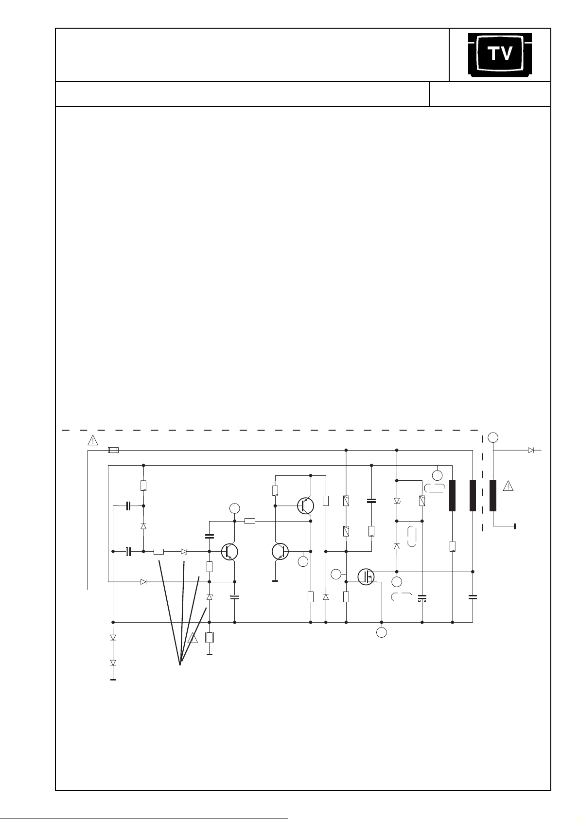
Colour television receivers with Digi Basic chassis, e.g. ST 70-255 IDTV/LOG,
M 70-280 IDTV/LOG, SE 7089 IDTV/LOG
Possible complaint:
Brown colouration of the circuit board near the diode D 60222 BZT 03D180. Simultaneously
the "+Eco" voltage is approx. 5V too high.
Reason:
Coincidence of unfavourable component tolerances.
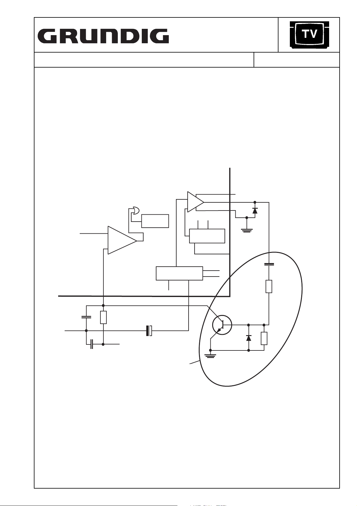
Cure:
Carry out the following changes in the stand-by mains stage:
- Change the Z-diode D 60203 from ZPD 9.1V to 8.2V.
- Change R 60202 from 68 kΩ to 1 kΩ.
- Connect an additional Z-diode ZPD 13 in series with R 60202. Connect the cathode of the
diode to the base of the transistor CT 60206.
- Check the rating of the resistor CR 60203 to be 2.2 kΩ.
Workshop:
Check the "+Eco" voltage. Carry out the changes if this voltage is higher than +17 V.
SI60201
T100mA
3456
330
R60222
F
C60224
12
D60208
D60207
P
C60201
1,5n
C60202
+
1u/63V
1N4001
1N4001
R60201
F
CD60201
CD60202
LS4148
1k
LS4148
CR60202
1k
CT60213
BC858B
100
R60213
D60202
ZPD13/2%
CC60203
CR60203
D60203
R60207
P
100p
2,2k
ZPD8,2V
4,7
5
CT60206
+
C60204
CR60206
1k
BC858C
10u/50V
P
CT60203
BC848B
4
CR60208
CR60214
4,7k
CD60223
components to be
Bauteile die zusätzlich
added or changed
einzubauen oder zu ändern sind.
68
3
LS4148
2,7M
R60211
2,7M
R60212
220K
CR60223
C60221
T60223
BUZ90A
G
F
R60221
D
S
6
n.V.
3,9n
D60222
330
D60221
2
n.V.
1
BZT03D180
n.V.
BA159
D60224
BYT54K
C60226
R60224
100k
10n/1000V
7
TR60220
100p/FKP1/1,6kV
D61001
BYT53B
M
Stores:
Z-diode ZPD 8.2 V part no. 8309-720-083
Z-diode ZPD 13 V part no. 8309-720-131
SMD resistor 1 kΩ part no. 8706-100-473
Technical Services / Information
8002/8012
S1/52067S0297
Page 10
SERVICE INFORMA TION
TVR 3701 SV 2/97
Television No.Product:
Portable mono TV/VCR combination TVR 3701 SV
Possible complaint:
Mains voltage dependent chirp audible in stand-by mode.
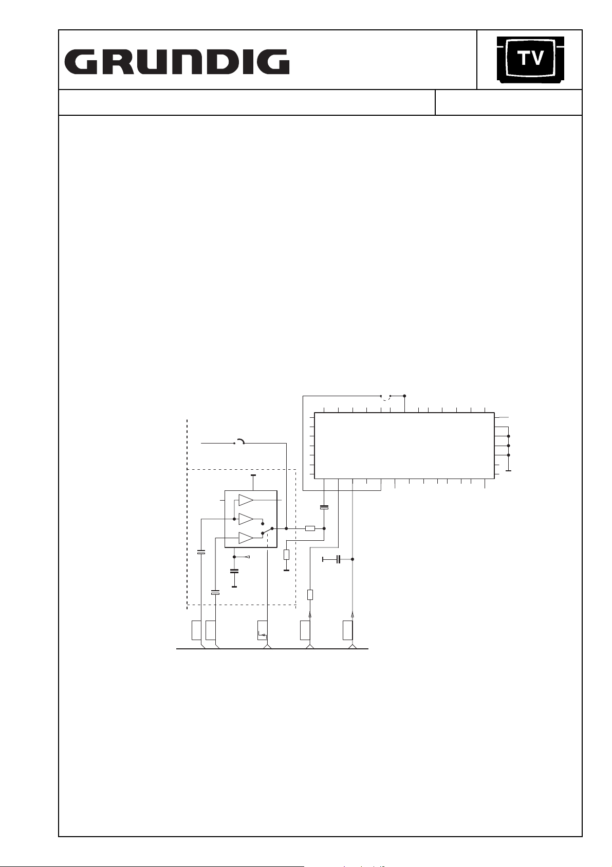
Cure:
Fit an additional transistor stage as shown below into the power supply unit at IC 7310
(MC 44603 P).
2
3
4
6
CURRENT
SENSE
THERMAL
SHUTDOWN
Buffer
Vref
Vcc
OVERVOLTAGE
MANAGEMENT
IC 7310
CURRENT SENSE
INPUT
7
3359
MC 44603P
330
fit these components
additionally
Dmax & SOFT-SART
CONTROL
2320
2,2 µ
diese Bauteile
zusätzlich einbauen
Workshop:
Carry out when complaints are received.
Stores:
Diode BAT 85 part no. 8309-198-085
11
UVLO1
Vref
BC 548 B
BAT 85
100 pF
4,7 kΩ
1 kΩ
Technical Services / Information
8002/8012 52067S0397
Page 11
SERVICE INFORMA TION
CUC 7301 3/97
Television No.Product:
37 cm colour television receivers with chassis CUC 7301 text e.g.: P 37-730 text
Possible complaint:
Teletext operation is not possible in “AV” programme position.
Reason:
The video switch-IC 2807 (TEA 2114) is not fitted in 37 cm television receivers.
Cure:
Retrofit the following components:
IC 2807 TEA 2114
C 2815 1 µF
C 2810 100 µF
C 2811 0.1 µF
CR 2813 270 Ω
CR 2814 270 Ω
In addition, change the polarity of 2.2 µF electrolytic capacitor C 2816 (negative terminal to
pin 8 of IC 2810) and remove bridge BR␣ 056.
BR 056
+
C2810
4
3
8
100u/25V
0dB
0dB
TEA 2114
6dB
7
CC2811
1
IC 2807
0,1u
2
6
CR2813
5
CR2814
270
34
33
32
31
30
29
28
270
+
C2816
M
R
CC2810
G
2,2u/100V
2,2n
19 18171615
B
BLANK
IC 2810
SAA 5254 P/E
1312
BR009
3736
RGB-REF
2524 2322 21
11
OSC IN
OSC OUT
32
1
6
272635
10
20
4
5
14
38
M
39
98 7
40
FBAS
+
C2815
1u/100V
SC
FBAS
EURO-AV
VQ
U
CR2807
H
SYNC
47k
V
SYNC
Workshop:
Carry out when complaints are received.
The circuit board is already prepared to be fitted with these components.
Stores:
IC TEA 2114 part no. 8305-362-114
Electrolytic capacitor 1 µF/100 V part no. 8452-967-325
Electrolytic capacitor 100 µF/25 V part no. 8452-967-135
Capacitor 0.1 µF part no. 8555-267-173
SMD resistor 270 Ω part no. 8706-297-059
Technical Services / Information 8002/8012 52097S0497
Page 12

Service Information
Product
Colour television receivers with chassis CUC 7303 and 7305, e.g. P 37-071,
T 51-720 text, T 55-731 text
Possible complaint:
After having replaced EEPROM IC 830 X24C02, the Automatic Tuning
System does not find all stations.
Reason:
The EEPROM on this chassis contains information about so-called band
limits in its memory cells 235 to 239. These values are programmed in the
factory in a special alignment adapter and vary with the individual tuner
and Z-diode D 683 (ZTK 33). When fitting a new EEPROM, any value is
stored in the memory cells. Consequently, the ATS does not scan the
complete frequency range.
Cure:
Clear the band limit values (content of the memory cells 235 to 239) as
follows:
1. Call up the Service Menu (depress button „i“ on the remote control
while switching on with the mains switch).
2. With the remote control buttons „P+/P-“ select line „AGC ALIGN“.
3. During a period of 5 seconds operate the buttons „AUX“ and „OK“
sequentially.
The ATS search function now scans the whole frequency range.
Note: When the band limits are cleared individual stations may be found
twice!
TV
Workshop:
Clear the band limit values when having replaced the tuner, Z-diode
D 683 or EEPROM IC 830.
Stores:
none
Note to our Service Information 1/97 (subject: Digi Basic colour television
receivers - „Eco“ voltage is about 5V too high)
Due to repeated inquiries we would like to point out that resistor R 60202
that is to be changed from 68 kΩ to 1 kΩ is a lead-type version and not a
SMD component.
Serial No 5/97
52127S0997, 8002/8012
Central
After-Sales Service
1/1
Page 13

Service Information
Product
Colour television receivers with chassis CUC 7350, e.g. ST 55-750 text
Possible complaint:
Despite the modifications carried out according to our TV Service
Information 9/96 the television sets switch occasionally to Standby
after a prolonged time of operation.
TV
Reason:
Temperature drift of the +E operating voltage by about 0.2 to 0.3V
caused by Z-diode CD 61023. Consequently, IC 34015 TDA 8374
switches off with sudden black/white changes in the picture content or
changing scenes.
This Z-diode has been introduced later and therefore is drawn in only
in the 1st Supplement to the CUC 7350 Service Manual.
Cure:
The position of the Z-diode is X=10, Y=150. Unsolder this diode and
insert a SMD resistor 1206 1.2Ω 1% in this place.
Stores
SMD resistor 1206 1.2Ω 1% part no. 8706-297-475
150
Lötseite
Copper Side
Serial No 6/97
10
S2R1521370000, 8002/8012
Central
After-Sales Service
1/1
Page 14

Service Information
6
2
3
Product
Colour television receivers with chassis CUC 7300, e.g. P 37-740 SAT, and all
sets retrofitted with the built-in satellite receiver SER 7300
Possible complaint:
The sound disappears suddenly during the reception of a satellite
programme and is audible again only when changing the programme or
switching the TV off and on again.
Reason:
IC MSP 3400 on the SAT Module hangs up by static charges entering the
Reset input of the IC.
Cure:
Unsolder the SMD capacitor CC 3800 from its place on the SAT Module
and resolder it at the place indicated on the figure below.
CC 3800 an dieser
Unsolder CC 3800
Resolder CC 3800 at
CC 3800 an dieser
this place
Position auflöten
CR3960
CBR74
CC3975
CC3961
CR3950
CR3949
CR3800
CR3942
CBR62
CC3947
CR3947
CC3948
CBR63
CC3974
CR3945
CT3947
CR3943
CC3945
CR3946
CC3966
CR3807
CR3941
CT3945
CBR31
CBR69
CBR66
CBR54
CBR64
CC3976
CBR30
CC39
CBR67
CBR56
CC3804
CBR58
CBR57
CBR
CBR53
CBR61
CR3802
CC3802
CR3801
CBR52
28
CC3806
1
CBR44
CBR55
CC3801
CBR43
CBR42
CR3804
CR3908
CIC3800
CBR39
CBR38
Position ausbauen
R3903
CR3906
CBR59
CC3803
CC3800
CBR51
15
CR3891
14
CBR50
CBR40
CBR48
CBR45
CC3958
CBR37
CBR34
CBR
CC3903
CR3915
CBR41
CBR47
CR3962
CBR49
CR3961
TV
CBR3
Stores:
none
S3/521570000, 8002/8012
Serial No.7/97
Central
After-Sales Service
1/1
Page 15

Service Information
Product
Colour television receivers with chassis Digi Basic CUC 1825, 1826 and
1827, e.g. ST 63-255 IDTV/LOG, M 70-281 IDTV/LOG, SE 7089 IDTV/LOG
Possible complaint:
The TV receiver can be switched on only with the remote control handset.
When switching on with the mains switch, the receiver always goes to
Standby mode.
Reason:
Unwanted activation of the protection circuit at the moment the TV
receiver is switched on.
Cure:
Change the electrolytic capacitor C 58004 (on pin 6 of IC 58010) from
10 µF to 22 µF/25V.
Workshop:
Carry out when complaints are received.
Important note: Since the Digi Basic TV receivers work without a wiper
contact in the mains switch the EEPROM stores the operating mode
(Standby or „On“) at the time the set is switched off with the mains
switch. That is why the set will only start with „On“ the next time it is
switched on (power on) if it was switched off from this mode.
TV
Stores:
Electrolytic capacitor 22 µF/25V part no. 8452-967-126
Serial No 8/97
S4/521970000, 8002/8012
Central
After-Sales Service
1/1
Page 16

Service Information
Product
Colour television receivers with Digi 6 chassis - CUC 1952, 1983, 1984 with
built-in SER 150/SER 150 ET Satellite Receiver - e.g. Denver SE 8216/9
Ref./PIP, M 82-269/9 Reference
Possible complaint:
On reception of the channel Premiere via satellite the connected decoder
does not operate while this station is decoded perfectly when received via
a cable installation.
Reason:
The video crossbar IC TDA 6417 is overloaded on satellite reception.
Cure:
Change the SMD resistor CR 43209 from 1 MΩ to 470 kΩ. It is also
possible to connect another 1 MΩ resistor in parallel when carrying out
repairs.
Workshop:
The position of the SMD resistor is X=102, Y=187.
Stores:
SMD resistor 470 kΩ 0805 part no. 8706-100-337
SMD resistor 1 MΩ 0805 part no. 8706-100-145
TV
52197S1297, 8002/8012
Serial No 9/97
Central
After-Sales Service
1/1
Page 17

Service Information
Product
Mono TV Recorders TVR 3710, 5100 and 5500
Possible complaint:
TV Recorder does not operate.
Reason:
Defect in transistor 7352 (MTP 3055E) caused by static discharges in the
TV Recorder.
Cure:
Fit an additional Z-diode BZX 83B15 between gate and source to suppress
voltage peaks at the gate.
Workshop:
The Z-diode must strictly be retrofitted if the transistor 7352 fails. This
change is carried out already in the factory.
Stores:
Z-diode BZX 83B15 part no. 8309-720-115
TV
MTP
3055E
G D S
LM317T
5D1
BZX 83B15
zusätzlich einbauen
fit additionally
7352
MTP 3055E
7351
BC 548B
3353
1 k
3354
14H
220 k
Serial No 10/97
522370000, 8002/8012
Central
After-Sales Service
1/1
Page 18

Service Information
Product
Colour television receivers with Digi IV chassis - CUC 1821/1851/1881/1892
and 1981, e.g. M 70-781 IDTV, M 70-791 IDTV, M 82-102 IDTV, M 95-102 IDTV,
M 82-169 PALplus
Possible complaint:
Mains supply switching transistor fails occasionally.
Reason:
Breaks may be found after a long time of use at the solder pads in the area
of the mains supply stage especially at the connections of the mains supply
transformer.
Cure:
Re-solder the connections in this area.
Workshop:
For reasons of operational reliability and irrespective of the fault, re-solder
the 1.5Ω resistor R 622 and the choke L 663 (both components are in the
area of the mains supply) with great care using ample tin.
Stores:
None
TV
522870000, 8002/8012
Serial No 11/97
Central
After-Sales Service
1/1
Page 19

Service Information
Product
Colour television receivers with 82/70 cm Toshiba picture tube and Digi 6
chassis - e.g. M 82-269/9 Ref, SE 8216/9 Ref/PIP, M 70-269/9 Ref, SE 7016/9
Ref/PIP Trento
Possible complaint:
Audible hum or buzzing noise from the bass loudspeaker.
Reason:
Magnetic radiation from the deflection yoke into the loudspeaker.
Cure:
To reduce the radiation from the yoke exchange the bass box loudspeaker
for a type with compensating coil.
Workshop:
Carry out when complaints are received.
Stores:
Loudspeaker with compensating coil, part no. 19154-031.61
TV
Product
Colour television receivers with Digi Basic chassis CUC 1805/1825/1826
and 1827, eg. ST 63-255 IDTV/LOG, ST 72-261 IDTV/LOG, Boston SE 7090
IDTV/LOG
Possible complaint:
TV set does not start occasionally.
Reason:
„Cold“ solder connection of the wire bridge „BR 129“ with the earthing pad
on the component side in the area of the mains supply stage. Consequently,
the standby power supply does not start up reliably.
Workshop:
Re-solder the chassis connection in every television receiver coming in for
repair using ample solder tin.
Stores:
None
Serial No. 12/97
S6/522870000, 8002/8012
Central
After-Sales Service
1/1
Page 20

Service Information
Product
Colour television receivers with chassis CUC 7301/7301F, e.g. P 37-070,
T 51-730 text, T 55-730/5 text
Possible complaint:
No picture. High tension is available.
Reason:
The transistors CT 181, CT 186, CT 191 and CT 193 failed because of high
voltage sparks inside the picture tube.
Cure:
Replace the defective transistors and solder an additional diode 1N4148
from pin 7 of the „RGB“ lead (to picture tube panel) to the ground pin 4 on
the chassis. Connect the anode of the diode with pin 4.
Workshop:
Fit the additional diode when the transistors failed.
Stores:
Diode 1N4148 part no. 8309-215-045
TV
Product
Correction of Service Information 9/97
Colour television receivers with Digi 6 chassis 1952, 1983, 1984 and built-in
satellite receiver SER 150/SER 150 ET - e.g. Denver SE 8216/9 Ref./PIP,
M 82-269/9 Reference
Possible complaint:
On reception of the channel Premiere via satellite the connected decoder
does not operate while this station is decoded perfectly when received via a
cable installation.
Reason:
The video crossbar IC TDA 6417 is overloaded on satellite reception.
Cure:
The change of the resistor CR 43209 from 1 MΩ to 470 kΩ as described in
our Service Information 9/97does not produce the desired effect in every
case. Therefore change the resistor CR 43209 from 1 MΩ to 330 kΩ when
carrying out repairs. It is also possible to connect a 560 kΩ resistor in
parallel with the 1 MΩ.
Workshop:
The position of the SMD resistor is X = 102, Y = 187.
Serial No 13/97
Stores:
SMD resistor 330 kΩ 0805 part no. 8706-100-333
SMD resistor 560 kΩ 0805 part no. 8706-100-139
R2S7/523070000, 8002/8012
Central
After-Sales Service
1/1
Page 21

Service Information
Product
Product
Colour television receivers with chassis CUC 7303, e.g. P 37-731 text,
P 45-731 text, T 55-731 text
Possible complaint:
Pronounced NF crackling when switching off with the mains switch.
Cure:
Change the Z-diode D 323 from ZPD 8.2V to 9.1V 2%. Additionally, solder a
diode 1N 4148 in parallel with the resistor CR 323. Connect the cathode of
this diode with the +B voltage.
Workshop:
Carry out on request. This change has already been introduced in
production.
Stores:
Z-diode ZPD 9.1V 2% part no. 8309-720-092
Diode 1N4148 part no. 8309-215-045
Colour television receivers with chassis CUC 7303/7305/7350 and the
picture tube panels 29305-022.16/-022.17, e.g. P 37-731 text, P 45-731 text,
T 55-731 text, P 37-731/12 text, ST 55-750 text, XS 55/1, Lissabon SE 5576
text
TV
Possible complaint:
Failure of the RGB output stages (picture tube panels 29305-022.16 and
-022.17) or of the teletext function.
Reason:
The semiconductors are destroyed by high-voltage sparks within the picture
tube.
Cure:
On the picture tube panels -022.16/-022.17, insert an additional 1.5 kΩ
composite carbon resistor (do not use a carbon film resistor!) into the circuit
path to the screen grid connection of the picture tube socket. Ensure that
the break is 2mm wide at least (see figure) to avoid sparking.
Workshop:
Refit the resistor in any case if the above
mentioned semiconductors failed.
Stores:
Only altered picture tube panels
29305-022.16/-022.17
Composite carbon resistor 1.5 kΩ,
part no. 8702-401-077.
additional resistor
zusätzlicher Widerstand
7
break
Trennstelle
Serial No 14/97
R3S8/523970000, 8002/8012
Central
After-Sales Service
1/1
Page 22

Service Information
Product
Colour television receivers with Digi 6 chassis CUC 1842, 1894, 1952, 1962
and 1983, e.g. M 72-410 Ref., Denver SE 8216/9 PAL Plus, M 70-269/9 Ref.
Possible complaint:
Vertical output stage TDA 4173 fails or thin white lines similar to retrace
stripes are visible.
Reason:
Inherent instability of the vertical output stage IC TDA 4173 AF.
Cure:
- Should above mentioned symptoms appear do not fail to exchange
TDA 4173 AF and solder additionally a 1 nF foil capacitor from pin 1 and
from pin 7 each to pin 4 (-K voltage) on the copper side.
- Check the mounting position of the vertical output-IC. If the position of
the IC is too low, the pins may temporarily come into contact with
the chassis connection on the upper side causing the IC to fail.
Additionally, the circuit may already be damaged by the building up
force of pressure resulting in a long-term failure. Therefore replace
TDA 4173 AF also if it has not been fitted correctly!
Workshop:
When fitting the new IC TDA 4173 AF take care of the correct position of the
holding clamp and solder in the additional capacitors!
This change has been generally introduced.
TV
Stores:
Foil capacitor 1 nF part no. 8555-367-525
IC TDA 4173 AF part no. 8305-344-173
correct position position is too low
≈5
Serial No 15/97
zu tiefe Montagerichtige Montage
52397S1897, 8002/8012
Central
After-Sales Service
1/1
Page 23

Service Information
Product
Colour television receivers with Digi Basic and Digi 6 chassis - CUC 1805,
1825, 1826, 1827, 1828, 1842, 1894, 1952, 1962 and 1983
e.g. M 72-410 Ref., Denver SE 8216/9 PAL Plus, M 70-269/9 Ref.
Possible complaint:
Interference lines in the picture or complete failure of the tuner.
Reason:
Failure of the PLL-IC TY 44860 within the tuner.
Cure:
After having replaced the tuner, solder an additional Z-diode ZPD 33 B
(2% tolerance) on the copper side of the chassis board from pin 1 to the
multipoint connector of the signal module to chassis (anode to chassis).
Workshop:
Retrofit the Z-diode if the tuner failed.
Stores:
Z-diode ZPD 33 B (2%) part no. 8309-707-135
TV
G1/524170000, 8002/8012
Serial No 16/97
Central
After-Sales Service
1/1
Page 24

Service Information
Product
Colour television receivers with Digi Basic chassis - CUC 1806, 1825, 1826,
1827, 1829, 1830 with the picture tube panels 29305-122.04/-122.10/-122.12
and -122.17
e.g. ST 70-255 IDTV/LOG, ST 72-261 IDTV/LOG, Atlanta SE 7220 IDTV/LOG,
ST 72-261 IDTV/LOG
Possible complaint:
Failure of the RGB output IC‘s TDA 6111.
Reason:
The RGB output IC‘s are destroyed by high voltage sparks.
Cure:
Directly from the outputs (pin 8) of the three output IC‘s TDA 6111 connect
one additional diode BAV 21 each to chassis and one diode each to the
+200 voltage (see figure).
Workshop:
The insertion of the three diodes which are to be connected to +200 is
already prepared on the picture tube panel by the diodes D 734, D 754 and
D 774.
The three diodes which are to be connected to chassis are to be soldered on
to the copper side from pin 8 to pin 4 (anode to pin 4).
TV
Stores:
Diode BAV 21 part no. 8309-200-021
IC TDA 6111 part no. 8305-336-111
Only modified picture tube panels 29305-122.04/-122.10/-122.12 and
-122.17.
+12V
2
3
9
1
TDA 6111
TDA 6111
+200
4
6
additional
zusätzliche
diode BAV 21
Dioden BAV 21
8
7
zur
to picture
Bildröhre
tube
Serial No 17/97
G2S9/524170000, 8002/8012
Central
After-Sales Service
1/1
Page 25

Service Information
Product
Colour television receivers ST 72-261 IDTV/LOG and ST 72-261/8 IDTV/LOG
with Toshiba picture tube
Possible complaint:
Picture seems to be unsharp or the TV switches occasionally to Standby.
Reason:
Short circuit in the serially connected capacitors C 64001 and C 64002
(150pF/6kV each) on the dynamic focusing board.
Cure:
1. Replace the capacitors C 64001 and C 64002 on the dynamic focusing
board.
2. Check the Ug2/focus control unit on the picture tube socket board
29305-122.12.
If the TV is fitted with version 29201-361.
unit must be replaced by version 29201-361.04. Version 29201-361.20
needs not to be replaced but can remain in the TV set.
3. Attention: When fitting the new Ug2/focus control unit, please note the
following wiring instructions:
- Insert the blue lead - provided with a white mark - of the Ug2/focus
control unit into the focus voltage connection of the diode split
transformer.
- Solder the shorter blue lead of the Ug2/focus control on to the focus
voltage connection of the focusing board.
- Route this lead from the focusing board to the focus voltageconnection
of the picture tube socket.
- Re-attach the cover of the focusing board.
4. Replace the diode split transformer 29201-680.01. Due to the failure of
the capacitor C 64001 or C 64002 the resistance of the focus resistor
in the diode split transformer changes so that an optimum adjustment of
the picture sharpness is no longer possible.
01 or -361.11, this focus control
TV
Workshop:
Please check the wiring of the focus leads according to point 3 of every
TV receiver of type ST 72-261 IDTV/LOG and ST 72-261/8 IDTV/LOG coming
in for repair!
Focus adjustment:
- Feed in a convergence test pattern.
Set contrast to maximum. Set the brightness so that the black
background of the test pattern just becomes visible.
- With the focus control on the picture tube socket board, adjust the
horizontal lines for maximum sharpness.
- Afterwards, adjust the vertical lines with the focus control on the
focusing board for maximum sharpness.
- Repeat this adjustment to achieve the best result possible.
Stores:
Capacitor 150pF/6kV part no. 8502-200-066
Ug2/focus control unit part no. 29201-361.04
Diode split transformer part no. 29201-680.01
Dynamic focusing board part no. 29305-025.26
52467S2097, 8002/8012
Serial No 18/97
Central
After-Sales Service
1/1
Page 26

Service Information
Product
Satellite Receivers STR 631/632/641 and 642
Possible complaint:
No sound after the receiver has been operated in standby mode for a
prolonged period of time. The sound is audible again only on disconnecting
the mains plug and switching the satellite receiver on again.
Reason:
As advised by our Service Information 4/97, this phenomenon is caused by
IC STV 400 STV 0056A but cannot be limited to certain IC lots.
Cure:
Solder one SMD Z-diode 8.2V each in parallel with the electrolytic
capacitors C 427 (pin 49 IC400) and C 436 (pin 38 IC400) which are
connected to chassis.
Workshop:
The additional Z-diodes can be soldered on to the copper side directly
between the connections of the electrolytic capacitors (anode to negative
connection of the electrolytic capacitor).
Retrofit the diodes in every satellite receiver coming in for repair.
Stores:
SMD Z-diode 8.2 C part no. 8309-455-082
TV
52497S2197, 8002/8012
Serial No. 19/97
Central
After-Sales Service
1/1
Page 27

Service Information
Product
Colour television receivers MW 70-100/8, M 72-100 and M 72-100/8
Possible complaint:
Audible buzzing noise that does not come out from the loudspeaker.
Reason:
The mains suppressor chokes on the mains switch module may be in
contact with the protective screen producing vibrations thereby.
Cure:
Unsolder the protective screen and the mains suppressor choke and fit a
suppressor choke with part number 29500-834.97. Since this choke is
provided with an additional compensating coil the protective screen is no
more needed.
Workshop:
Carry out on request.
Stores:
Mains suppressor choke part no. 29500-834.97
TV
52497S2297, 8002/8012
Serial No. 20/97
Central
After-Sales Service
1/1
Page 28

Service Information
Product
Series GV 4xx video recorders with „World Deck“
Possible complaint:
Drive mechanism does not move.
Reason:
Slipping of the bevel gear of the pulley shaft (pos. 47) and / or worm
shaft (pos. 48).
Cure:
Replace the pulley shaft and / or worm shaft.
Note:
To replace the pulley shaft quickly follow the instructions given below:
Dismantle the drive mechanism, set the drive mechanism to EJECT
position, remove the cassette compartment, remove the threading
belt, detach the worm shaft and the pulley shaft,
cut the motor holder with a knife as shown on the figure below,
pull out the pulley shaft, fit and snap in the new pulley shaft and worm
shaft, refit the cassette compartment as described in the Service
Manual.
VIDEO
Stores:
Pulley shaft (pos. 47) part no. 75988-001.14
Worm shaft (pos. 48) part no. 75988-001.24
Cut off with a knife
Serial No.1/97
5311670000, 8002/8012
Central
After-Sales Service
1/1
Page 29

Service Information
Product
GV 560 HiFi
Possible complaint:
Video recorders react to the TV remote control handset.
Reason:
The 10bit evaluation is active.
Cure:
Replace the EPROM by the current version COG 560HI / 1.92
The 10bit evaluation can be disabled as follows:
Depress the „CODE“ button.
Enter the number „8527“ and confirm with the „OK“ button.
The entry will not be acknowledged by a message like „ON“ or „OFF“
on the display.
If the video recorder was disconnected from the mains supply the code
number is to be entered anew.
Test:
Depress and hold the „VIDEO“ button on the TV remote control
handset and call up a video recorder function.
If above mentioned setting is successfully transferred to the video
recorder, the selected function must not be carried out.
VIDEO
Stores:
EPROM COG 560HI / 1.92 part no. 27599-007.64
Serial No. 2/97
53117700, 8002/8012
Central
After-Sales Service
1/1
Page 30

Service Information
Product
GV 6096 SV
Possible complaint:
Controlling a satellite receiver is not possible.
Reason:
The Cinch connecting socket for controlling a satellite receiver
is not fitted.
Cure:
Retrofit the Cinch connecting socket on request.
Stores:
Cinch connecting socket part no. 27511-495.01
VIDEO
53121700, 8002/8012
Serial No. 3/97
Central
After-Sales Service
1/1
Page 31

Service Information
Product
Series GV 4xx video recorders with „World Deck“
Part number changed from that specified in Service Information 1/97
The pulley shaft (pos. 47) and the worm shaft (pos. 48) are combined
and offered as one repair kit.
Stores:
Repair kit part no. 75988-018.24
Kit A is still available under part no. 75988-001.24
VIDEO
531237000, 8002/8012
Serial No. 4/97
Central
After-Sales Service
1/1
Page 32

Service Information
Product
GV 6096 SV
Possible complaint:
The scanning clock of VPS-controlled timer recordings is carried out
incorrectly or not at all.
Reason:
Faulty software.
Cure:
Change the EPROM to version PCOG 1 - 4 U.
Stores:
EPROM PCOG 1 - 4 U part no. 27599-007.76
VIDEO
531247000, 8002/8012
Serial No. 5/97
Central
After-Sales Service
1/1
Page 33

Service Information
Product
GV 660 / GV 690
Possible complaint:
Master/Slave and Synchro Edit control functions do not work.
Reason:
In a small number of GV 660 and GV 690 video recorders, the 7-pin
cable (pos. 9511) from the keyboard control unit to the teletext
module is not inserted correctly (laterally inverted) on the keyboard
control unit.
Cure:
Disconnect the 7-pin cable from connector 1511 on the teletext
module, turn it by 180 degrees and refit it.
Test:
Check the 5-pin Edit socket
(from pin 3 to pin 4)
3
4
Ohm
VIDEO
Good = 1-2 MOhm approximately
Bad = 5 kOhm approximately
Note:
There is a description of the PC interface used in the GV 660 and GV 690
video recorders.
It is available under part number 72010-529.30.
Serial No. 6/97
53287000, 8002/8012
Central
After-Sales Service
1/1
Page 34

Service Information
Product
Series GV 5xx and GV 6xx
Supplement to Service Information 2/97
The 10bit evaluation function can be switched off with all video
recorders which can be operated with the RP 500 or RP 540 remote
control handset.
VIDEO
531277000, 8002/8012
Serial No. 7/97
Central
After-Sales Service
1/1
Page 35

Service Information
Product
GV 403, 407, 411/1, 411/2, 417, 437, 4001, 4002 VPS, 4003 VPS
Original mains supply units: 27599-003.05/.10
A few video recorders are fitted with a mains supply unit with the
wrong part number label on it (27599-003.00).
When ordering the IC SPH 4690 with part number 75988-000.60, the
type IC TDA 4605/3 with a MOSFET will be supplied under part number
75988-002.40 as a replacement.
Note:
Changes are necessary when fitting the delivered replacement to
original mains supply units.
Changes:
1. Solder a 4.7 kOhm resistor instead of bridge 3035.
2. Bridge 8002 is omitted.
3. Solder bridge 8003 (connection between Y 7035 gate and IC 7005
pin 5).
4. Pos. No. Y 7035 for MOSFET.
5. Pos. No. Y 7005 for TDA 4605/3.
VIDEO
The 4.7 kOhm resistor is commonly available.
Serial No. 8/97
531337000, 8002/8012
Central
After-Sales Service
1/1
Page 36

Service Information
Product
GV 7400 HIFI and variants, SE 7105 HIFI
Possible complaint:
Disturbances and noise along with the HIFI sound.
Reason:
No steady audio-FM signal identified on playing back.
Cure:
Carry out the following changes on the chassis board - head amplifier.
1. Change CR 3082 from 100Ω to 470Ω.
2. Change CC 2089 from 220p to 150p.
3. Add CR 1kΩ to CC2089.
Stores:
Components are commonly available.
VIDEO
IC STV 5712
( 7080 )
PIN 8
( Pos. 3082 )
470Ω
( Pos. 2089)
150p
Circuit extract:
Chassis Board - Head Amplifier
Service Manual 72010-530.25
page 4 - 30
FMAP
1kΩ added
added
1kΩ
150p
CC 2089
Serial No. 9/97
531467000, 8002/8012
Central
After-Sales Service
1/1
 Loading...