

Page 1

Service Document
Exchange Set
RRCD 1300
Service
Manual
Sicherheit
Safety
Materialnr./Part No.
720108000001
Dieses Service Dokument ist nur in Datenform verfügbar
This Service Document is only available as data
Änderungen vorbehalten/Subject to alteration
Made by GRUNDIG in Germany • HS-41 0305
http://www.grundig.com
Es gelten die Vorschriften und Sicherheitshinweise
gemäß dem Service Manual "Sicherheit", Material-
S
nummer 720108000001, sowie zusätzlich die eventuell abweichenden, landesspezifischen Vorschriften!
The regulations and safety instructions shall be
valid as provided by the "Safety" Service Manual,
S
part number 720108000001, as well as the
respective national deviations.
ǵ
Page 2
A L I G N M E N T P R O C E D U R E
y
y
(
INSTRUMENTS REQUIRED GENERAL PREPARATION
1. Signal Generator 1. Check source voltage, DC or AC according to specificaions
2. FM Signal Generator 2. Set function switch to band being aligned
3. FM/AM IF Sweep Generator (10.7 MHz for FM) 3. Signal input should be kept as low as possible to avoid AGC and AFC function
4. VTVM 4. Standard modulation :
5. Oscilloscope
6. Frequency counter
7. Regulated DC power supply
AM IF ALIGNMENT
SIGNAL SOURCE (AM RF Gen.)
STEP
1 loop
2 Repeat step 1 for max. output
CONNECT TO
A standard radiation
SET SIGNALTOALIGNMENT INDICATOR (Oscilloscope, VTVM)
465KHz Detector output terminal
and ground
CONNECT TO
TP5
FM IF ALIGNMENT
This model requires no FM IF alignment as the IF is fixed by ceramic filter and discriminator CF503 & CF504. Please take note that correct type and same color dot of ceramic filter is used
in servicing, diff color dot of ceramic filter may cause worse IF 'S' curve characteristic and distortion.
Connect IF genescope output terminal to TP3 & TP4 (GND) in series with a 1000Pf capacitor, connect scope input terminal to TP5 & TP4 (GND), then the IF characteristic curve can be
observed.
FM RF ALIGNMENT
STEP
SIGNAL SOURCE (FM Signal Gen.)
1
2
3
4
5
Repeat steps 3 and 4 as necessary to minimize tracking error and also steps 1 and 2 if necessar
CONNECT TO
TP1 & TP2 108.25 MHz Terminals VC 501A Volume
through matching network (modulated) across speaker (Highest end) (Osc. trimmer) Maximum control at
if necessary voice coil L503 (RF coil) max. position
SET SIGNALTOALIGNMENT INDICATOR (Oscilloscope, VTVM)
87.35 MHz (Lowest end) stretch or
(modulated) squeeze
88 MHz 88 MHz stretch or
(modulated) squeeze
106 MHz VC 501B
(modulated) 106 MHz (RF trimmer)
CONNECT TO
AM 1 KHz 30% mod
FM 1 KHz 22.5 KHz dev
SET RADIO
DIAL TO
Quiet Volume control at
Point
SET RADIO
ADJUST ADJUST FOR REMARKS
T501 Maximum
DIAL TO
ADJUST ADJUST FOR REMARKS
L502 (Osc. coil)
min. position
AM RF ALIGNMENT
STEP
SIGNAL SOURCE (AM Signal Gen.)
1
2
3
4
5
Repeat steps 3 and 4 as necessary to minimize tracking error and also steps 1 and 2 if necessar
CONNECT TO
A standard radiation (modulated) Across speaker (Highest end) (Osc. trimmer) Maximum control at
loop ant. 600 KHz voice coil L 504 max. position
SET SIGNALTOALIGNMENT INDICATOR (Oscilloscope, VTVM)
515 KHz T 502
(modulated) (Lowest end) (Osc. coil)
1635 KHz VC 501C Volume
(modulated) 600 KHz (ant. coil)
1400 KHz VC 501D
(modulated) 1400 KHz (ant. trimmer)
CONNECT TO
SET RADIO
DIAL TO
ADJUST ADJUST FOR REMARKS
ALIGNMENT PROCEDURE FOR CD SECTION
Applicable unit :
1 This model is using CD drive unit No. SANYO DA11B3V
2 The alignment for CD section is fully automatic and no adjustment is reguired
GENERAL PREPARATION -
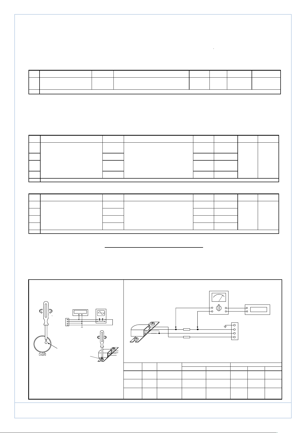
A ) MEASURING INSTRUMENTS REQUIRED FOR TAPE B ) EQUIPMENTS REQUESTED FOR AC BIAS FREQUENCY / CURRENT ADJUSTMENT :
SPEED AND HEAD AZIMUTH ADJUSTMENT.
( 1 ) TAPE SPEED ADJUST
MTT-211NA (3150 Hz) TEST
SPEAKER
TERMINALS
MOTOR
( 2 ) HEAD AZIMUTH ADJUSTMENT . Test Point Adjust Frequency Frequency Observe at Observe
2.1 - Connect the equipments as shown in the Fig. 1. at Beat 0 Beat 1 Beat 2 Beat 0 Beat 1 Beat 2
TAPE IS REQUIRED
(The Both Speakers loading Are Required) Resistor
2.2 - Insert a test tape
2.3 - Press PLAY and set VOLUME at reference output.
2.4 - Adjust the azimuth adjustment screw for the max.
& balance ch. output on both ch. of oscilloscope.
2.5 - Secure above screw with glue after adj. completed.
1 ) Check source voltage, DC or AC according to specifications . 2 ) Set function switch to Tape being aligned .
°
FREQUENCY
COUNTER
3150 Hz
AZIMUTH ADJ. SCREW
CH. 1
R/P HEAD
OSCILLOSCOPE
FIG.1
10 KHz : MTT-114 ) into deck.
CH. 2
FIG.2
R/P HEAD
AC BIAS FREQUENCY ALIGNMENT :
Note :The test unit should be keep in recording mode and added two resistors Ra & Rb as shown in the
Ra
10 ohm
Rb
10 ohm
Fig. 2 before alignment. be sure to delete the both resistors Ra & Rb after alignment completed.
Ra or Rb L401 60 KHz ± 0.3K
INPUT
VTVM
OUTPUT
4
1
SO457
FREQUENCY
COUNTER
62KHz
==> TO CASS PCB
CN207
ǵ
RRCD 1300
Page 3
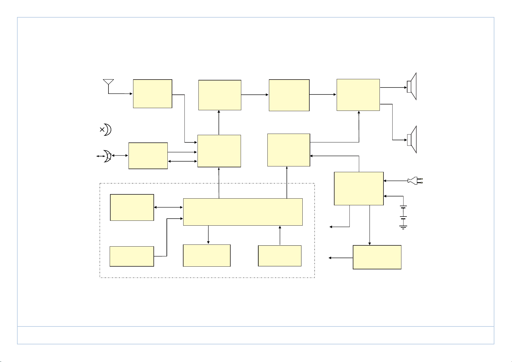
R
FM ANTENNA
E. HEAD
TUNER
IC 501
U.B.S.
Q206 Q207
AUDIO
CONTROL
VR351
POWER
AMPLIFIER
IC201
-CH SP
L-CH SP
R/P HEAD
CD
MECHANISM
KEY BOARD
TAPE R/P
IC 401
DA11 B3N
FUNCTION
SELECTOR
REC
SW 201
CD SERVO SYSTEM
U701 U702
CD DISPLAY
MUTING
CIRCUIT
Q204 Q205
IR RECEIVER
9V MAIN SUPPLY
D301 D302
D303 D304
DC 9V
DC 6V
Q201 Q202 Q203
AC IN
BATT.
12V
6V REG
ǵ
RRCD 1300
Page 4
ǵ
RRCD 1300
Page 5
ǵ
RRCD 1300
Page 6

C526
140P(NPO)
TO CD POWER
CN206
2PINS
CD 7V
1
PW GND
2
TO RADI O PCB
L CH
1
GND
2
R CH
3
RA 7V
4
CN207
4PINS
SW201D
SK43D06-GB7
RA
TA
CD
1
2
3
4
5
6
7
CN208
7PINS
TO CD SECTION
VC501D
PVC126
54
L504
MW ANT
1
P501
MW
P502
1
MB
VC501C
PVC126
16
15
14
13
R CH
A GND
L CH
SYNC
OP. LED.
3V3 PROTECT
MUT E
RADI O PCB
PRC200-1-05-00
VC501B
C524
5n
1
C523
22P(N330)
P503
MR
1
P504
MG
5 3
MW/ LW OSC
3
2
1 6
T502
RED
7
9330
SW201C
SK43D06-GB7
12
11
10
9
R257
5K6
4.5X3T5
PVC126
52
4
R233
56K
SW201A
SK43D06-GB7
RA
TA
CD
D205
1N4148
L503
12
FM ANT
P510
TP1
D501
1N4148
C528
10u
C236
u47
4
3
2
1
R256
5K6
C522
22P(N330)
+
+
L502
5x2T5
C502
C503
D502
1N4148
TP2
R234
C244
68P(NPO)
VC501A
12
PVC126
51
20P
C501
30P
30P
C504
10n
680K
R230
+
SW501
SS22F16-G6
FM
C533
MW
+
1u
R517
4K7
7P
C521
20
21
22
23
24
IC501
1234567
+
+
u47
4u7
CF501
C506
L501
56K
C234
1 2
C237
9014C
u47
u47
Q207
R255
4.5X3T5
+
330
C505
R511
330K
R501
Q206
9014C
SYNC REC
TP3
1 6
2
3
T501
2492
AM IF YELLOW
10
R236
27K
C242
1n8(M)
R231
680K
CN202
8PINS
R-REC
GND
L-REC
R-CH
GND
L-CH
7V
TO TAPE PCB
7
+
8
7
6
5
4
3
2
1
465KHz
R235
3K3
C235
u47
68P(NPO)
C519
C518
19
4
R232
27K
C241
1n8(M)
C245
R352
SW351A
2P2TD
C517
100n
1n
u47
+
18
( SP2111 )
R512
R229
3K3
8K2
R516
8 17
330
1
2
3
1K
10.7MS3
R351
16
91011 14
CF504
R502
40n(Y5P)
560
R508
3K3
+
C516
1u
15
TP4
R503
470
470
PRC2000-1-65-00
40n(Y5P)
C353
4
5
6
SW351B
2P2TD
R-CH
1
GND
2
L-CH
3
CN201
3PINS
C351
C515
100n
C509
10n
12 13
CF503
10.7 MG77
LED PCB
R355
8K2
R354
560
SO351
3PINS
C507
100n
CN501
2PINS
1
2
3
R-CH
GND
L-CH
2
1
R510
C513
+
4u7
C512
10n
+
C510
4u7
TP6
C511
1n2(M)
C520
470u
2
1
CN651
2PINS
VOLUM E PCB
C356
1n
8
C354
120n(M)
R356
2K7
C355
3
1n
4
120n(M)
1
C352
R353
2K7
PRC2000-1-35-00
AUDI O POWER PCB
PRC200-1-02-00
12K
R513
12K
R504
18K
R505
12K
+
R509
LED651
3MM GREEN
7
50KB
VR351B
6
5
R-CH
GND
L-CH
SO352
3PINS
2
VR351A
50KB
220
1
2
3
TP5
C514
1n2(M)
R506
R507
RA 6V
18K
12K
L-CH
GND
R-CH
CN503
4PINS
1
2
3
4
CN502
2PINS
CN209
1
2
R225
1
2
3
3PINS
10K
Q204
R-CH
GND
L-CH
R226
C232
9014C
10K
+
CN552
2PINS
PRC2000-1-55-00
R221
5K6
R222
5K6
1u
SW551A
1
2
SKE22F03
SWITCH PCB
R207
33K
R228
1K5
+
C233
470u
+
1u
C230
+
C231
Q205
1N4148
1u
9014C
D210
R205
47K
R206
5K6
9014C
Q208
1N4148
123
D203
220
Q203
9014C
R219
SW551B
SKE22F03
R202
33K
7V REG.
C225
C224
C228
+
1u
+
100u
1
+
( 7V )
+
C452
1n
C203
100u
Q202
R203
9014C
220K
R201
39K
Q201
2SB772Q
CN551
2PINS
R204
2
1K
UNIT : RESISTOR IN OHM
CAPACITOR I N F
INDUCTOR I N H
UNLESS OTHER SPECIFY
8
RA
7
6
TA
5
CD
SW201B
SK43D06-GB7
MOTOR
CN205
3PINS
B+IN
B+OUT
GND
123
+-
TAPE SWITCH
POWER SUPPLY SECTION
IN4001
D301
C301
20n
20n
C302
D302
IN4001
C303
20n
C304
20n
1000u 16V
C306
+
D303
IN4001
D304
IN4001
P301
20n
C305
P302
P303
DC OUT
1
AC1
1
AC2
1
TRANSFORMER
T503
X'FRM
AC SOCKET
AC
DC IN
P304
115
T H E R M A L
F U S E
1
L505
DC
C
9V
1
P30 5
GND
456
C202
20n
1u
C201
DECK MECH.
+12V
C210
47K
47K
GND
R242
C246
220u
+
F1510100D
LF302
R-CH
GND
L-CH L-CH
+
C211
3
2
4
11
108
100n(M)
C218
100n
C216
C214
C217
100u
+
+
100u
100n
R217
1.5
C212
1000u
Q210
+
R218
C213
100n(M)
+
C215
1000u
2200u 16V
9014C
R241
1.5
R239
390K
R240
15K
C249
220u 16V
1u
C222
100u
+
+
+
C223
100u
R220
220
+
6
5
9
7
DV3287B
IC201
Q209
8550C
1
C209
10u
12
GND
2
2
1
1
CN301
CN211
2PINS
2PINS
R-CH
GND
CN262
4PINS
+
5ohm7 5ohm7
POWER SUPPLY PCB
1006-1-03-00
PHONE SECTION
C253
2n
C254
2n
L262
3T5
R261
150
R262
150
4
4
L261
3T5
STJ 5P/2P2T
J261A
5
4
3
2
1
L263
3T5
R263
150
150
R264
123
123
R-CHL-CH
+
-
ǵ
RRCD 1300
Page 7

ǵ
RRCD 1300
Page 8

DA11T3CN
CN701
VC
VDD
GND
LD
VR
MD
F(+)
T(-)
T(+)
F(-)
CN703
2PINS
1
2
Q709
9014C
E
D
A
B
C
F
1
2
3
4
5
6
7
8
9
10
11
12
13
14
15
16
CD 6V
PW GND
L703
3T5
R773
D701
1N4148
22K
R774
220K
C739
470u
GND
R701
91
MGND
L702
3T5
220u
100n
SGND
MVDD
R705
Q701
4.7
R702
2SA933AS
C702
10n
100u
CD SERVO PCB
PRC2000-1-07-00
DA11
CN702
SPIND+
SPINDSLED+
SLED-
INNER
GND
C740
VCC(6V)
100n
Q703
2SB1237
C741
C742
VDD
TP714
SGND
C703
3V3
4.7
TP713
VDD
R750
R749
47K
C701
1
2
3
4
5
6
0
100u
R704
R703
10K
100K
1K
R752
R751
R713
TP706
RFRPRFM
C721
150P
TP705
TZCRFM
C722
2n2
TP704
C747
18K
R715
TE
75K
C723
R722
100P
C724
6n8
1u
63
60
61
64
62
RFI
TEN
EQO
1
2
3
4
5
6
7
8
9
10
11
12
13
14
15
16
6K8
R716
CAGC
AVDD1
AC
BD
VBIAS
E
F
AGND1
FEN
FEO
PKC
BTC
PD
LD
ASY
AVDD2
PCO
FCO17AGND218FDOUT19JUMPO20TDOUT21SDIN22SDOUT23CLVOUT24ADC0/G AIN_SEL25ADC1/KEY26CLK8827LON28SEGa/CO M029SEGb/CO M130SEGc/CO M231SEGd/CO M3
390K
R717
33K
4K7
100n
R719
C718
C717
10u
R718
R723
9K1
TP715
SP
TP716
SD
R725
8K2
TP717
FD
R724
4K7
TP718
TD
R726
0
100u
AVDD
C704
OPEN
C706
OPEN
100n
100u
150K
100n
3u3
0.22u
Q702
DTC114TSA
R768
TP707
TDOUT
28
27
26
25
24
23
22
21
20
19
18
17
16
15
C705
100n
47K
OPEN
TP703
RF
C711
470P
C712
100n
C713
100n
R714
470
TP708
JUMPO
C744
47u
C750
220u
C745
100n
C746
4u7
AGND
TP701
VC
0
1
2
3
4
5
6
7
8
9
10
11
12
13
10K
14
R767
C707
OPEN
C708
C709
TP702
C710 120P
FE
R712
C714
C715
C716
IC702
BA5826FP
VO1(-)
POW GND
VO1(+)
VIN1
VO4(+)
RESET
REG B
REGOUT
MUTE
REGGND
IN2'
IN2
VO2(+)
VO3(+)
VO2(-)
POW GND
OPIN(-)
OPOUT
R753 10K
C743
R706 47K
R707 47K
R708
R709 47K
R710 56K
R711 56K
VO4(-)
IN4
IN4'
BIAS
VCC
VCC
IN3'
VIN3
VO3(-)
RSTT
OPEN
27K
R721
57
59
58
SC
TEO
TZCRFM
IC701
BU24530-9A
C719 100n
55
56
AGND3
RDACO
RFRPRFM
TP709
TP710
R746 10K
R747 10K
SEGa/COM0
SEGb/COM1
SEGc/COM2
SEGd/COM3
SEGe/SEG0
SEGf/SEG1
SEGg/SEG2
SEG./SEG3
COM0/SEG4
COM1/SEG5
R762
4K7
Q707
R763
22K
2SA933AS
R729 2K2
R728
2K2
C726
100n
C725
51
52
54
DGND
AVDD3
LDACO53VCDAC
PWC/W _REMO TE
P03/PRO _LED
P02/MM UTE
SEG6/AM UTE
COM1/SEG 5
COM0/SEG 4
SEGa/COM0
SEGb/COM1
C720 100n
R748
R754 100
R755 100
R756 100
R757 100
R758
R759 100
R760 100
R761 100
C734
100n
C727
R727
220
R720 1M
50
49
XI
XO
DVDD
RESET B
P11/SYNC
P10/PLAY
P01/LID
P00/INNER
SEG./3
SEGg/2
SEGf/1
SEGe/0
R739 OPEN
32
R740 470K
R741 OPEN
R742 OPEN
R743 OPEN
R744 470K
R745 470K
SEGc/COM2
SEGd/COM3
7K5
R764
4K7
R765
22K
C733
560P
AFVCC
100u
100
Q7082SA933AS
R731 2K2
R730
2K2
560P
C728
15P(A)
X701
16.9344MHz
C729
15P(A)
100n
48
47
46
45
44
43
42
41
40
39
COM1/SEG5
38
COM0/SEG4
37
SEG./SEG3
36
SEGg/SEG2
35
SEGf/SEG1
34
SEGe/SEG0
33
C735
C736
560P
DGND
X101:TDK FCR16.93M2G
DVDD
C730
C731
100u
R734
1K
1
2
3
4
5
6
7
8
9
10
11
12
13
14
CN705
14PINS
C737 4u7
C738 4u7
560P
L701
100uH
COM1/SEG5
COM0/SEG4
SEG./SEG3
SEGg/SEG2
SEGf/SEG1
SEGe/SEG0
SEGd/COM3
SEGc/COM2
SEGb/COM1
SEGa/COM0
1
2
3
4
5
6
7
8
9
10
11
12
13
14
CN805
14PINS
C732
PROGRAM
R732
100n
D802
100K
R733
R736
10K
R735
100K
TP720
TP721
TP722
TP723
TP724
TP725
TP726
TP727
TP728
TP729
TP730
TP731
TP732
TP733
R737
100K
D803
10K
>/II
DTA124ESA
Q704
R766
330
D804
REPEAT
R771
82K
R772
82K
AFGND
TP719
123
123
1K8
R851
2K7
R852
3K3
R853
4K7
R854
R855
10K
789
10
12345 6
R775
22K
R769
4K7
CN706
3PINS
CN856
3PINS
K850
PLAY
STOP
REPEAT
K851
K852
K854
K853
K855
PROG
FF
FR
L704
OP. LED.
DIS801
2D-LED
3T5
OPEN
2
CLOSE
1
CN707
CD DOOR
KEY CONTROL PCB
PRC2000-1-85-00
Pin30
Pullup
Pulldow n
Pin31
Pullup
Pulldow n
Pin32
Pullup
Pulldow n -12db
Tracking
0db
0db
+3db
+3db +3db
+6db +3db
GAIN SELECT OPTION
D801
PRC2000-1-08-00
DISPLAY PCB
R.CH
A.GND
L.CH
SYNC.
OP.LED.
3V3 PRODECT
MUTE
DISP.
LED
LCD
CDM
TCP-11TK2X
DA11T3CN
SEARCH_MUTE
NO SOUND
R748Focus
0db OPEN
+3db
22K
12K
0db
7K5
4K7
+6db+3db
1K8
SHORT
+6db+6db
R748
CN704
1
2
3
4
5
6
7
7PINS
ǵ
RRCD 1300
Page 9

L.CH OUT
L-CH
R-CH
GND
COMMAN
R.CH OUT
7V
Q401
9014C
1
2
3
4
CN401
4PINS
16
17
18
SW401F
PS-82D06
19
20
21
SW401G
PS-82D06
7
8
9
SW401C
PS-82D06
3
2
1
4
6
7
L401
9170
10
11
12
SW401D
PS-82D06
22
23
24
SW401H
PS-82D06
D401
1N4148
13
14
15
SW401E
PS-82D06
C402
10n
+
C404
47u
C405
10n
D402
1N4148
4
5
6
SW401B
PS-82D06
+
C401
1000u
C406
1n8(m)
R450
3K9
R453
120K
R454
1K
R455
820K
R456
100
R401
120
R405
1M
+
C403
47u
R402
470
R410
10K
R411
47K
+
C410
1u
R412
680K
Q402
9014C
R414
4K7
+
C411
1u
R413
470
R420
470
R421
10K
R423
680K
Q403
9014C
R422
47K
R424
4K7
+
C420
1u
R441
10K
R431
10K
Q404
9014C
Q405
9014C
R404
10K
R403
10K
R442
6K8
R432
6K8
C413
18n(m)
C424
18n(m)
+
C414
47u
+
C423
47u
R444
82K
R434
82K
+
C422
1u
+
C412
1u
R445
10K
R435
10K
C425
1n5(M)
C415
1n5(M)
C416
2n7(M)
C426
2n7(M)
+
C421
1u
+
C407
22u
R415
180K
R425
180K
R436
10K
R446
10K
R452
150
R430
12K
R440
12K
1
2
3
4
5
6
7
8
9
IC401
LS22241
C427
1n5
C417
1n5
R443
68
R433
68
R426
5K6
R416
5K6
SYNC
L-OUT
GND
R-OUT
L-REC
R-REC
GND
REC. 6V5
REC GND
1
2
CN403
2PINS
C409
180P
C408
180P
C418
1n
C419
1n
TO R/P HEAD
TO MAIN PCB
1
2
3
4
5
6
7
8
CN402
8PINS
NF(R)
IN(R)
OUT(R)
GND
ALC
Vcc
OUT(L)
IN(L)
NF(L)
PLAY HEAD NO. 4211
ǵ
RRCD 1300
Page 10

1
2
3
4
5
6
7
8
9
12
13
14
15
16
17
18
19
20
10
11
IC601
PT2221-001/UPC6121-001
K10
K11
K12
K13
REM
VDD
SEL
OSCO
OSCI
VSS
CCS
KI /O0
KI /O1
KI /O2
KI /O3
KI /O4
KI /O5
KI /O6
KI /O7
LM P
K602
STOP
K604
SKIP+
K606
REPEAT
K601
PLAY
K603
SKIP-
Q601
2SC1740
CF601
455KHz
D
IR_LED
R601
1
+
C603
10u/10V
C601
100P
C602
100P
+3V
GND
ǵ
RRCD 1300
Page 11

ǵ
RRCD 1300
Page 12

ǵ
RRCD 1300
Page 13

ǵ
RRCD 1300
Page 14

ǵ
Ersatzteilliste
Spare Parts List
3 / 2005
POS. NR. ABB. MATERIAL-NR. ANZ. BEZEICHNUNG DESCRIPTION
POS. NO. FIG. PART NUMBER QTY.
757123445000 RRCD 1300 CHROME/VERO RRCD 1300 CHROME/VERO
0001.000 759551128900 TUER CASSETTE CASSETTE DOOR
0002.000 759551129300 LINSE TUER CASSETTE CASSETTE DOOR LENS
0003.000 759551129500 EINSATZ CASSETTE EMPLOYMENT CASSETTE
0004.000 759551128600 FEDER TUER CASSETTE SPRING CASSETTE DOOR
0015.000 759551129400 TASTENSATZ CASSETTE TASTE SET CASSETTE
0025.000 759551128500 LAUFWERK CASS. CS-21V-1006-C CASS. MECHANISM CS-21V-1006-C
0035.000 759551129600 ABDECKUNG SPEICHERBATTERIE DOOR BATTERIE MEMORY
0036.000 759551129100 BATTERIEFACHABDECKUNG DOOR BATTERY
0061.000 759551129200 TRAGEGRIFF HANDLE
0063.000 759551129000 TUER CD CD DOOR
0064.000 759550615400 FEDER TUER CD 1,2MM SPRING TUER CD 1,2MM
0065.000 759551128700 TELESKOPANTENNE TELESKOPANTENNE
0070.000 S 759550615100 LAUFWERK CD DA11-T3CN CD MECHANISM DA11-T3CN
0150.000 S 759551128800 NETZANSCHLUSSKABEL AC POWER CORD
720114052000 BEDIENUNGSNLEITUNG INSTRUCTION MANUAL
NUR FÜR INTERNEN GEBRAUCH
FOR INTERNAL USE ONLY
AUDIO
RRCD 1300
MATERIAL-NR. / PART NO.: 757123445000
BESTELL-NR. / ORDER NO.: GDP5600 CHROME/VERO
d©
TAUSCHGERAET EXCHANGE SET
D/GB/F/I/P/E/NL/PL/DK/S/FIN D/GB/F/I/P/E/NL/PL/DK/S/FIN
ǵ
Es gelten die Vorschriften und Sicherheitshinweise
gemäß dem Service Manual "Sicherheit", Mat.-Nummer 720108000001, sowie zusätzlich die eventuell abweichenden, landesspezifischen Vorschriften!
The regulations and safety instructions shall be valid
!
as provided by the "Safety" Service Manual, part
number 720108000001, as well as the respective
( ! )
national deviations.
ÄNDERUNGEN VORBEHALTEN / SUBJECT TO ALTERATION
RRCD 1300
 Loading...