

Page 1
RR 620 CD / RR 650 CD Allgemeiner Teil / General Section
SERVICE MANUAL
Service
Manual
RR 620 CD
RR 650 CD
Sach-Nr./Part No.
72010-751.70
Zusätzlich erforderliche Unterlagen
für den
Komplettservice:
Additionally
required Service
Manuals for the
Complete Service:
ULTRA BASS SYSTEM
Service
Manual
Sicherheit
Safety
Sach-Nr./Part No.
72010-800.00
CD TAPE RADIO
/OFF
UBS
SURROUND
SOUND
MIN
RR 620 CD
RR 650 CD
kHz
1600
100
1400
140
1200
120
1000
100
FM
ART
ST
R
E
RO
C
H
C
N
Y
S
D
SKIP / SEARCH
C
R
R
6
5
0
C
D
R
A
VOLUME
REMOTE
SENSOR
O
R
D
I
N
G
OPEN/
CLOSE
D
C
H
T
I
W
R
E
D
R
O
D
C
IO
E
C
A
SS
ETTER
PLAY PAUSE
POWER
MW
LW
FM
TUNING
STEREO
REPEAT PROG.
PLAYBACK/
RECORD 2
R
R
6
5
0
C
D
RADIO
CASSE
O
C
E
R
E
T
T
RR 650 CD
STOP
REMOTE
CONTROL
D
C
H
IT
W
R
E
D
R
PLAY
STOP
NEXT
PREV.
VOLUME
RR 620 CD (75.3119-1051 / G.DG 6151)
RR 650 CD (75.3120-1051 / G.DG 6251)
CD Remote Control (75954-046.34)
Änderungen vorbehalten Printed in Germany Service Manual Sach-Nr.
GRUNDIG Service 1 - 1
Subject to alteration VK 231/233 0996 Service Manual Part No. 72010-751.70
Page 2

Allgemeiner Teil / General Section RR 620 CD / RR 650 CD
Es gelten die Vorschriften und Sicherheitshinweise gemäß dem Service Manual "Sicherheit",
Sach-Nummer 72010-800.00, sowie zusätzlich
die eventuell abweichenden, landesspezifischen
Vorschriften!
j
Inhaltsverzeichnis
Seite
Allgemeiner Teil ............................ 1 - 2 … 1 - 9
Meßgeräte / Meßmittel .............................................................. 1 - 2
Technische Daten...................................................................... 1 - 3
Servicehinweise......................................................................... 1 - 3
Bedienhinweise.......................................................................... 1 - 4
Ausbauhinweise......................................................................... 1 - 6
Einstellvorschriften....................... 2 - 1 … 2 - 3
Schaltpläne und
Druckplattenabbildungen........... 3 - 1 … 3 - 18
Verdrahtungsplan ...................................................................... 3 - 1
Schaltpläne:
Tuner..................................................................................... 3 - 3
Cassette ................................................................................ 3 - 5
CD ......................................................................................... 3 - 7
Bedienteil ............................................................................ 3 - 11
Klangregelung...................................................................... 3 - 13
NF-Teil, Stromversorgung ................................................... 3 - 15
Platinenabbildungen:
Tuner..................................................................................... 3 - 3
Cassette ................................................................................ 3 - 5
CD ......................................................................................... 3 - 8
Bedienteil ............................................................................ 3 - 11
Klangregelung...................................................................... 3 - 14
NF-Teil, Stromversorgung ................................................... 3 - 17
The regulations and safety instructions shall be
valid as provided by the "Safety" Service Manual,
part number 72010-800.00, as well as the respective national deviations.
k
Table of Contents
Page
General Section............................. 1 - 2 … 1 - 9
Test Equipment / Aids ............................................................... 1 - 2
Technical Data........................................................................... 1 - 3
Service Hints............................................................................. 1 - 3
Operating Instructions ............................................................... 1 - 5
Disassembly Instructions........................................................... 1 - 6
Adjustment Procedures ............... 2 - 3 … 2 - 5
Circuit Diagrams and
Layout of PCBs ........................... 3 - 1 … 3 - 18
Wiring Diagram .......................................................................... 3 - 1
Circuit Diagrams:
Tuner..................................................................................... 3 - 3
Cassette ................................................................................ 3 - 5
CD ......................................................................................... 3 - 7
Control Board....................................................................... 3 - 11
Tone Control ........................................................................ 3 - 13
AF Part, Power Supply ........................................................ 3 - 15
Layout of the PCBs:
Tuner..................................................................................... 3 - 3
Cassette ................................................................................ 3 - 5
CD ......................................................................................... 3 - 8
Control Board....................................................................... 3 - 11
Tone Control ........................................................................ 3 - 14
AF Part, Power Supply ........................................................ 3 - 17
Explosionszeichnungen
und Ersatzteillisten ....................... 4 - 1 … 4 - 4
Explosionszeichnung RR 620 CD ............................................. 4 - 1
Ersatzteilliste RR 620 CD .......................................................... 4 - 2
Explosionszeichnung RR 650 CD ............................................. 4 - 3
Ersatzteilliste RR 650 CD .......................................................... 4 - 4
Allgemeiner Teil
Meßgeräte / Meßmittel
Trenntrafo Wobbelsender
Meßsender Oszilloskop
Frequenzzähler Tonhöhenschwankungsmesser
DC-Voltmeter NF-Voltmeter
Testcassette 449 Sach-Nr. 35079-019.00
Drehmomentcassette 456 Sach-Nr. 35079-014.00
Test-CD Sach-Nr. 72008-376.00
Beachten Sie bitte das GRUNDIG Meßtechnik-Programm, das Sie
unter folgender Adresse erhalten:
GRUNDIG electronics GmbH
Würzburger Str. 150, D-90766 Fürth/Bay
Tel. 0911/703-0, Telefax 0911/703-4479
Exploded Views and
Spare Parts Lists........................... 4 - 1 … 4 - 4
Exploded View RR 620 CD ....................................................... 4 - 1
Spare Parts List RR 620 CD...................................................... 4 - 2
Exploded View RR 650 CD ....................................................... 4 - 3
Spare Parts List RR 650 CD...................................................... 4 - 4
General Section
Test Equipment / Aids
Isolating Transformer Sweep Generator
Test Generator Oscilloscope
Frequency Counter Flutter Meter
DC Voltmeter AF Voltmeter
Testcassette 449 Part No. 35079-019.00
Cassette torque meter 456 Part No. 35079-014.00
Test CD Part No. 72008-376.00.
Please note the Grundig Catalog “Test and Measuring Equipment”
obtainable from:
GRUNDIG electronics GmbH
Würzburger Str. 150, D-90766 Fürth/Bay
Tel. 0911/703-0, Telefax 0911/703-4479
1 - 2 GRUNDIG Service
Page 3
RR 620 CD / RR 650 CD Allgemeiner Teil / General Section
Technische Daten
Spannungsversorgung:
Netzbetrieb ................................................................ 230V, 50/60Hz
Batteriebetrieb ................................. 8 Monozellen 1,5V (R20, UM1)
Verstärkerteil:
Ausgangsleistung (DIN 45324, 10% THD):
Musikleistung ......................................................................... 2 x 4W
Sinusleistung ...................................................................... 2 x 2,6W
Stereo-Kopfhörer-Klinkenbuchse ........................................3,5mm ø
Rundfunkteil:
Wellenbereiche ................................................... FM: 87,5 - 108MHz
MW: 526,5 - 1606,5kHz
LW: 148,5 - 283,5kHz
Zwischenfrequenzen ...................................... 10,7MHz und 465kHz
Antennen ....................................................Teleskopantenne für FM
eingebaute Ferritstab-Antenne für MW/LW
Cassettenteil:
Tonträger ..................................Compact-Cassette nach DIN 45516
Spurlage ...................................................... Viertelspur international
Bandgeschwindigkeit ..................................................... 4,76cm/sec.
Motor..................................................................... Gleichstrommotor
Frequenzübertragungsbereich .................................... 125Hz - 8kHz
Geräuschspannungsabstand.....................................................45dB
Gleichlauffehler........................................................................0,35%
Automatik ............................ Aussteuerungsautomatik bei Aufnahme
Automatisches Auslösen der Tasten am Bandende
Technical Data
Power Supply:
Mains operation .........................................................230V, 50/60Hz
Battery operation ...............................8 mono cells 1.5V (R20, UM1)
Amplifier Section:
Output power (DIN 45324, 10% THD):
Music power........................................................................... 2 x 4W
Nominal power.....................................................................2 x 2,6W
Jack socket for stereo headphones..................................... 3.5mm ø
Radio Section:
Wavebands......................................................... FM: 87.5 - 108MHz
MW: 526.5 - 1606.5kHz
LW: 148.5 - 283.5kHz
Intermediate frequencies ................................ 10.7MHz and 465kHz
Aerials ......................................................... Telescopic aerial for FM
Built in ferrite rod aerial for MW/LW
Cassette Section:
Cassette.......................................... Compact cassette to DIN 45516
Track System.............................................International quartertrack
Tape Speed ................................................................... 4.76cm/sec.
Motor.................................................................................. DC motor
Frequency Range ........................................................125Hz - 8kHz
S/N Ratio (weighted) ................................................................ 45dB
Wow and Flutter.......................................................................0.35%
Automatic ...................................... Automatic recording level control
Automatic button release at tape end
CD-Teil:
Frequenzübertragungsbereich .................................... 20Hz - 20kHz
Geräuschspannungsabstand.....................................................65dB
Servicehinweise
Cassettenteil
Überprüfen Sie vor Beginn der Service-Arbeiten, ob die Magnetköpfe,
die Tonwelle und die Gummiandruckrolle frei von Bandabrieb sind.
Zum Reinigen dieser Teile verwenden Sie ein mit Spiritus oder
Reinigungsbenzin getränktes Wattestäbchen; dadurch verbessert sich
der Aufnahme- und Wiedergabepegel, sowie der Bandlauf.
Nach dem Ersatz von Magnetköpfen oder sonstiger Bauteile müssen
die technischen Daten des Gerätes anhand der im Service Manual
vorgegebenen Meßwerte überprüft bzw. eingestellt werden.
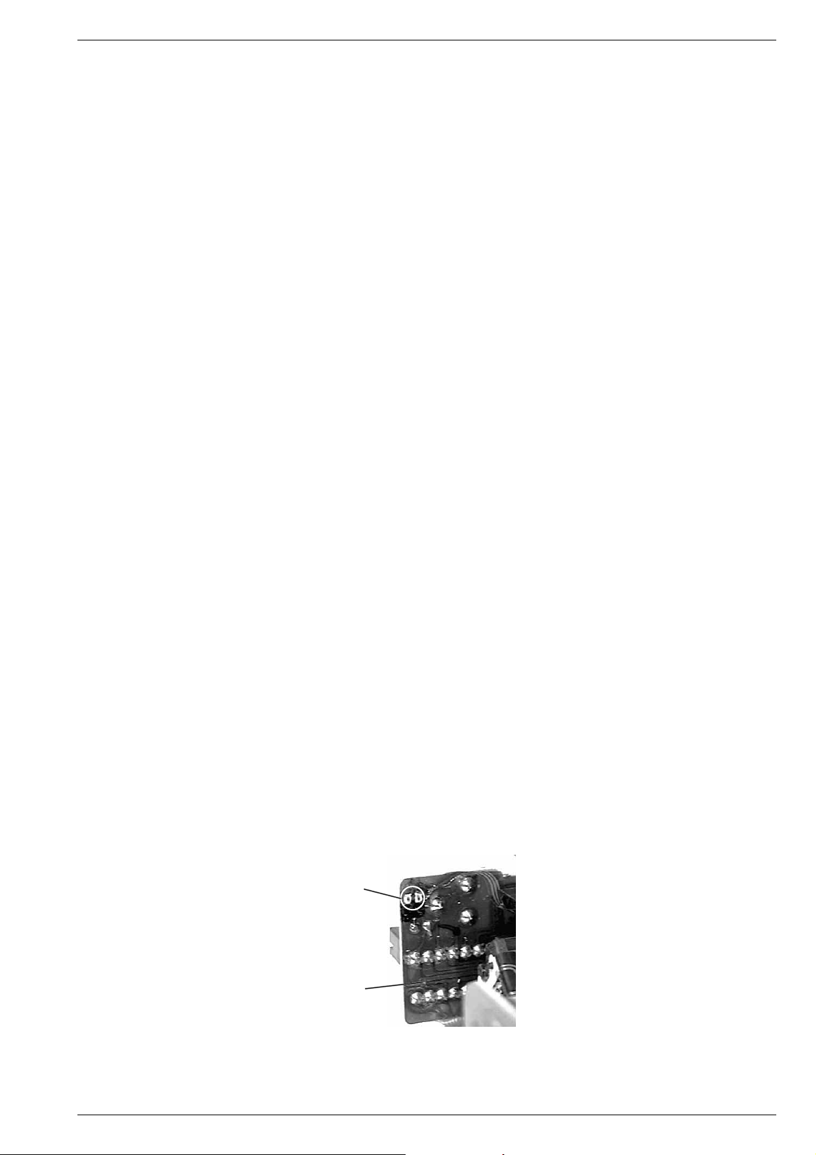
CD-Teil
Bei Ausbau des CD-Laufwerks muß vor Abziehen der Steckverbindungen eine Schutzlötstelle auf der Leiterplatte der Lasereinheit
angebracht werden, um eine Zerstörung der Laserdiode durch statische Aufladung zu vermeiden.
Beim Einbau einer neuen Lasereinheit muß nach Einstecken der
Steckverbinder die werkseitig angebrachte Schutzlötstelle entfernt
werden!
CD Section:
Frequency range.......................................................... 20Hz - 20kHz
S/N ratio, weighted ................................................................... 65dB
Service Hints
Cassette Section
Before commencing service work, ensure that the magnetic heads, the
capstan and the pinch roller are free from particles produced by tape
abrasion. The recording and playback levels and the tape run can be
improved by cleaning these parts with a cotton-wool tip soaked in spirit
or cleaning benzine.
If the heads or other components have been replaced, the technical
data of the recorder must be checked or adjusted according to the
values specified in the Service Manual.
CD Section
When removing the CD mechanism the Laser pick-up PCB must be
provided with a protective soldered joint before unplugging the connectors to avoid damage to the Laser diode by static charges.
When inserting the new Laser pick-up the soldered joint fitted at the
factory must be removed after the connectors are plugged in.
Schutzlötstelle
protective soldered joint
Laseranschlußplatte
Laser PCB
GRUNDIG Service 1 - 3
Page 4
Allgemeiner Teil / General Section RR 620 CD / RR 650 CD
1 - 4 GRUNDIG Service
D
Bedienhinweise
Hinweis: Dieses Kapitel enthält Auszüge aus der Bedienungsanleitung. Weitergehende Informationen entnehmen Sie bitte der gerätespezifischen Bedienungsanleitung, deren Sachnummer Sie in der
entsprechenden Ersatzteilliste finden.
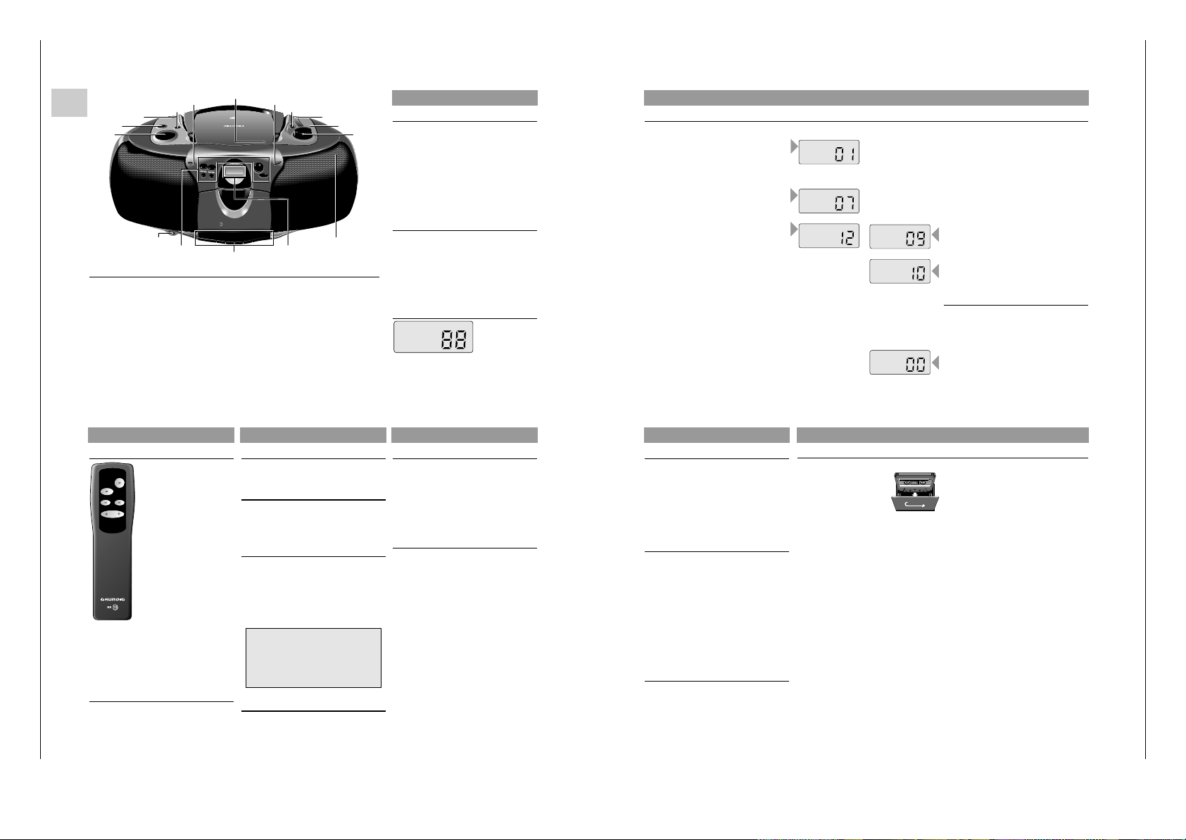
BEDIENELEMENTE
CD Control
SKIP/SEARCH
∞/56/§ –
zum Überspringen von Stücken
und zum Suchen in Vorwärtsoder Rückwärtsrichtung
REPEAT –zum Wiederholen eines
Titels/aller Titel
PROG. –zum Programmieren von Titeln
im Speicher
PLAY/PAUSE 2;– zum Starten/Unterbrechen der
Wiedergabe
STOP 9 –
zum Stoppen der Wiedergabe
Cassette Control
0 –Starten der Aufnahme
B –Starten der Wiedergabe
Q –schneller Rücklauf
R –schneller Vorlauf
9//
–Stoppen des Bandlaufs und
Öffnen des Cassettenfacks
; –unterbrechen der
Wiedergabe/Aufnahme
CD Display
PROGRAM: Abspielen des Programms
PLAY: Wiedergabe
PAUSE: PAUSE
REPEAT 1: Wiederholung eines Stücks
REPEAT: Wiederholung aller Stücke
REPEATPROGRAM
PLAY
PAUSE
1
Ober- und Vorderseite
(die Abbildung zeigt: RR 650 CD)
VOLUME – zum Einstellen der Lautstärke
UBS – ein/aus des ULTRA BASS SYSTEM
FUNCTION – CD: zum Umschalten auf CD-Betrieb/Einschalten
– TAPE/OFF: zum Umschalten auf Cassettenbetrieb/Ausschalten
– RADIO: zum Umschalten auf Radiowiedergabe/Einschalten
SURROUND SOUND – ein- und ausschalten des Surround-sound-Effektes
(nur RR 650 CD)
REMOTE SENSOR – zur Empfangen der Fernbediensignale
(nur RR 650 CD)
OPEN/CLOSE – zum Öffnen der CD-Deckels
POWER
6 – leuchtet auf, wenn das Gerät eingeschaltet ist
BAND – zum Wählen zwischen FM, MW, und LW
SCALE – Abstimmskala
FM STEREO 6 – leuchtet auf, wenn ein UKW-Stereo-Sender empfangen wird
TUNING – zum Abstimmen auf einen Radiosender
p – Buchse für Stereo-Kopfhörer
MIC – eingebautes Mikrophon unter dem Lautsprechergitter
C
D
S
Y
N
C
H
ROST
ARTR
E
C
O
R
D
I
N
G
R
R
6
5
0
C
D
R
A
D
IO
C
A
S
S
ETTER
E
C
O
R
D
E
R
W
I
T
H
C
D
OPEN/
CLOSE
TUNING
MW
LW
FM
SKIP / SEARCH
REPEAT PROG.
PLAY PAUSE
STOP
POWER
REMOTE
SENSOR
PLAYBACK/
RECORD
2
REMOTE
CONTROL
R
R
6
5
0
C
D
RADIO
CASSE
T
T
E
R
E
C
O
R
D
E
R
W
IT
H
C
D
kHz
1600
1400
1200
1000
100
140
120
100
FM
STEREO
C
D
T
A
P
E
R
A
D
IO
/O
FF
ULTRA BASS SYSTEM
UBS
SURROUND
SOUND
VO
LUM
E
MIN
VOLUME
UBS
FUNCTION
SURROUND
SOUND
REMOTE
SENSOR
OPEN/CLOSE
SCALE
BAND
TUNING
FM STEREO 6
CD Display
p
MIC
CD Control
Cassette Control
POWER 6
KLANGREGULIERUNG
Volume
• Stellen Sie die gewünschte Lautstärke mit dem
VOLUME-Regler ein.
UBS (Ultra Bass System)
• Drücken Sie die Taste UBS, um die Baßtone
hervorzuheben:
w UBS AUS
x UBS EIN
Surround Sound (nur RR 650 CD)
Diese Funktion erstellt einen zusätlichen 3-dimensionalen Effekt des Stereoklangs, der von den
Lautsprechern ausgetauscht wird.
• Drücken Sie SURROUND SOUND, um diesen
Effekt ein-und auszuschalten.
w SURROUND SOUND AUS
x SURROUND SOUND EIN
Kopfhörerbuchse p
• Sie können einen Stereo-Kopfhörer mit
3,5 mm
Stecker an die Buchse p anschließen.
– Die Lautsprecher werden damit abgeschaltet.
Hinweis:
Die Klangregler können bei der Wiedergabe
von Radio, CD oder Cassette verwendet
werden.
Jedoch haben sie keinen Einfluß auf die
Cassettenaufnahme.
RADIO
Radioantennen
– Bei UKW-Empfang (FM) die Teleskopantenne
herausziehen und durch Neigen und Drehen
ausrichten. Bei zu starkem UKW-Signal (in
Sendernähe) empfiehlt es sich die Antenne
einzuschieben.
– Für
MW/LW-E
mpfang hat das Gerät eine eingebaute Antenne. Die Teleskopantenne kann
also eingeschoben bleiben. Zum Ausrichten der
Antenne das ganze Gerät drehen.
Rundfunkempfang
• Den FUNCTION-Schalter auf RADIO stellen.
– Die Einschaltanzeige POWER 6 leuchtet auf.
• Den Ton mit den Reglern VOLUME, UBS und
SURROUND SOUND
(nur RR 650 CD)
einstellen.
• Sie können einen Stereo-Kopfhörer mit
3,5 mm
Stecker an die Buchse p anschließen.
– Die Lautsprecher werden damit abgeschaltet.
• Den Wellenbereich mit dem BAND-Schalter
wählen.
• Mit dem TUNING-Knopf auf den Sender
abstimmen.
– Wenn die Angabe FM STEREO 6 erscheint,
empfangen Sie einen UKW-Stereo-Sender.
• Treten bei UKW-Stereo-Empfang aufgrund einer
nicht ausreichenden Signalstärke Störungen auf,
können diese unterdrückt werden, indem
FM MONO/STEREO auf FM MONO geschaltet
wird.
– Die FM STEREO-Anzeige 6 erlischt und der
UKW-Sender wird in Mono wiedergegeben.
• Das Gerät ist ausgeschaltet, wenn sich der
FUNCTION-Wahlschalter in der Position TAPE
befindet und keine Tasten gedrückt sind.
– Die Einschaltanzeige POWER
6 erlischt.
BEDIENELEMENTE
Fernbedienung (nur RR 650 CD)
Batteriewechsel
Läßt die Reichweite Ihres IR-Gebers
nach oder lassen sich einzelne
Funktionen nicht mehr ausführen,
sollten Sie die Batterien
auswechseln.
Verwendeter Batterietyp 2x Micro
1,5 Volt LR03, Größe AAA.
Öffnen Sie zum Batteriewechsel
den Deckel des Batteriefaches
auf der Rückseite des Gebers.
Achten Sie auf die richtige
Polung der Batterien (Markierung
im Batteriefach beachten).
Umwelt-Hinweis: Denken Sie
beim Batteriewechsel daran:
Batterien sind Sondermüll.
PLAY 2 – Starten/Unterbrechen der
Wiedergabe
STOP 9 – Stoppen der Wiedergabe
PREV. ¡ – zum Überspringen von Stücken und
zum Suchen in Rückwärtsrichtung
NEXT ™ – zum Überspringen von Stücken und
zum Suchen in Vorwärtsrichtung
– VOLUME + – zum Einstellen der Lautstärke
Rückseite
FM MONO/STEREO / BEAT CUT:
– Wenn der BAND-Schalter auf FM steht:
Auswahl zwischen FM STEREO und FM MONO
– Wenn der BAND-Schalter auf MW/LW steht:
zum Unterdrücken eventueller Pfeifgeräusche bei
MW(AM)-Aufnahmen
AC MAINS: Netzanschlußbuchse
STOP
PREV.
NEXT
PLAY
VOLUME
CD-SPIELER
•
Zum Starten des Abspielens auf PLAY/PAUSE 2;
drücken.
– Sobald das Abspielen beginnt, erscheinen 'PLAY'
und die Nummer des laufenden Stücks.
• Den Ton mit den Reglern VOLUME, UBS und
SURROUND SOUND
(nur RR 650 CD)
einstellen.
• Für kurzzeitige Unterbrechungen auf
PLAY/PAUSE 2; drücken.
–
Im Anzeigefeld erscheint das Zeichen 'PAUSE'.
• Zum Fortsetzen der Wiedergabe die Taste
PLAY/PAUSE 2; erneut drücken.
• Zum Stoppen auf STOP 9 drücken.
– Das Display zeigt die Anzahl der Titel auf der
CD.
–
Der CD-Spieler geht ebenfalls in Stellung STOP:
– wenn Sie auf OPEN/CLOSE drücken;
– wenn das Ende der CD erreicht wird;
– wenn die Batterien ausgehen oder bei
anderen Stromunterbrechungen.
•
Zum Herausnehmen der CD öffnen Sie den
Deckel durch Drücken der OPEN/CLOSE-Taste.
• Den CD-Deckel erst öffnen wenn sich der CDSpieler in Stellung STOP befindet.
Wahl eines anderen Titels während der
Wiedergabe
•
Taste ∞/5oder 6/§drücken, bis die Nummer
des gewünschten Titels im Anzeigefeld erscheint.
– Die Wiedergabe wird unterbrochen, und kurz
danach beginnt die Wiedergabe des gewählten
Stücks.
Beginnen mit einem bestimmten Titel
•
Taste ∞/5oder 6/§drücken, bis die Nummer
des gewünschten Titels im Anzeigefeld erscheint.
• Taste PLAY/PAUSE 2; drücken.
– Die Wiedergabe beginnt beim Titel mit der
eingegebenen Nummer.
Rasches Suchen einer Passage
• ∞/5 gedrückt halten, um in Richtung Plattenanfang zu suchen.
• 6/§ gedrückt halten, um in Richtung Plattenende zu suchen.
Hinweis:
Dies ist ein 'hörbares Suchen'.
Während des Suchens wird die Lautstärke reduziert
und nach dem Loslassen der Taste wird die
Lautstärke auf ihren normalen Wert zurückgestellt.
Wiederholung eines Titels
• Durch einmaliges Drücken von REPEAT wird ein
Musiktitel wiederholt.
– Im Anzeigefeld erscheint: 'REPEAT 1'
Wiederholung der CD
• Durch nochmaliges Drücken von REPEAT werden
alle Musiktitel wiederholt.
– Im Anzeigefeld erscheint: 'REPEAT'
• Um den REPEAT-Modus auszuschalten, drücken
Sie die Taste REPEAT erneut.
Programmieren
Sie können maximal 21 Titel in jeder beliebigen
Reihenfolge speichern. Beim Versuch mehr als 21
Titel zu speichern, wird die Programmierfunktion
von Anfang an wiederholt.
Speichern eines Programms
•
In Stellung STOP, drücken Sie die Taste PROG..
Auf dem Display erscheint die Angabe '00'.
• Wählen Sie den gewünschten Titel mit den
Tasten ∞/5 oder 6/§.
• Speichern Sie diese Nummer durch Drücken der
PROG.-Taste.
• Wählen und speichern Sie in dieser Weise alle
gewünschten Titel.
REPEAT
PLAY
REPEAT
1
PLAY
PAUSE
PLAY
PLAY
Abspielen einer CD
CD-SPIELER
Kontrolle des Programms
• In Stellung STOP, wenn Sie wiederholt die Taste
PROG. drücken, zeigt das Display nacheinander
alle gespeicherten Stücknummern in Reihenfolge.
Titel dem Programm hinzufügen
• Drücken Sie mehrmals PROG. bis im Display
'00' erscheint.
• Nun können Sie zu der aktuellen Reihenfolge,
wie oben beschrieben, weitere Titel speichern
(bis zu 21).
Abspielen des Programms
• Drücken Sie einmal PROG., um den ersten Titel
des Programms anzeigen zu lassen.
• Taste PLAY/PAUSE 2; drücken.
–
Das Abspielen beginnt mit dem ersten Programmtitel.
– Im Anzeigefeld erscheint: 'PROGRAM PLAY'
– Nach dem letzten Titel wird die Wiedergabe
gestoppt.
–
Das Display zeigt die Anzahl der Titel auf der CD.
Hinweise:
• Sie können die Wiedergabe durch Drücken der
Taste STOP 9 beenden.
•
Während der Wiedergabe eines Programms können
mit den Tasten ∞/5 oder 6/§ die gewünschten
programmierten Titel angewählt werden.
Löschen eines Programms
• Drücken Sie STOP 9 um die Wiedergabe des
Programms zu beenden.
• Der Inhalt des Programms wird gelöscht:
– durch Öffnen des CD-Fachs mit der Taste
OPEN/CLOSE;
– wenn der FUNCTION-Schalter betätigt wird;
– wenn die Batterien ausgehen oder bei anderen
Stromunterbrechungen.
CASSETTENDECK
• Öffnen Sie den Cassettenhalter mit 9//.
• Legen Sie eine Cassette ein.
• Beim Mithören der Aufnahme,
den Ton mit den Reglern
VOLUME, UBS und
SURROUND SOUND
(nur
RR 650 CD)
einstellen.
Die Stellung dieser Regler hat keinen Einfluß auf
die Aufnahme.
• Zum Aufnahmestart auf 0 drücken (die Taste B
rastet automatisch mit ein).
– Wenn das Bandende erreicht ist, werden die
Recorder-Tasten freigegeben.
• Zum Unterbrechen der Aufnahme die Taste
;
drücken.
• Zum Fortsetzen der Aufnahme die Taste
; erneut
drücken.
• Die Taste 9// drücken, wenn die Aufnahme vor
Erreichen des Bandendes gestoppt werden soll.
Durch erneutes Drücken dieser Taste öffnet sich
das Cassettenfach.
• Das Gerät ist ausgeschaltet, wenn sich der
FUNCTION-Wahlschalter in der Position TAPE
befindet und keine Tasten gedrückt sind.
– Die Einschaltanzeige POWER
6 erlischt.
CD Synchro – Aufnahme vom CD-Spieler
• Den FUNCTION-Schalter auf CD stellen.
• Sie brauchen den CD-Spieler nicht separat zu
starten: sobald Sie auf 0 drücken, startet der
CD-Spieler automatisch.
– Steht der CD-Spieler in Stellung STOP, startet
die Aufnahme vom Anfang der CD (oder vom
Anfang des gespeicherten Programms).
• Um eine Aufnahme in der Mitte eines Stücks
zu starten, beginnen Sie die CD-Wiedergabe
wie gewohnt.
• Sobald die gewünschte Passage erreicht ist,
drücken Sie auf Pause und anschließend auf
0, um die Aufnahme zu starten.
Aufnahme vom Radio
• Den FUNCTION-Schalter auf RADIO stellen.
• Mit dem BAND-Schalter den Wellenbereich
wählen.
• Mit dem TUNING-Einsteller auf den
gewünschten Radiosender abstimmen.
• Bei Aufnahme von UKW-Sendern den Schalter
FM MONO/STEREO auf die gewünschte
Position stellen.
•
Wenn während der Aufnahme eines MW/LWSenders Pfeifgeräusche zu hören sind, können
diese unterdrückt werden, indem der Schalter
BEAT CUT auf die andere Position gestellt wird.
Mono-Aufnahme vom eingebauten Mikrophon
• Den FUNCTION-Schalter auf TAPE stellen.
• Den VOLUME-Regler auf Null stellen (ein
Mithören während Mikrophonaufnahmen ist
nicht möglich).
• Um eine gute Aufnahme zu gewährleisten,
sollte ein Abstand von 30 – 100 cm zum
Mikrofon eingehalten werden.
Aufnahme
Page 5
RR 620 CD / RR 650 CD Allgemeiner Teil / General Section
GRUNDIG Service 1 - 5
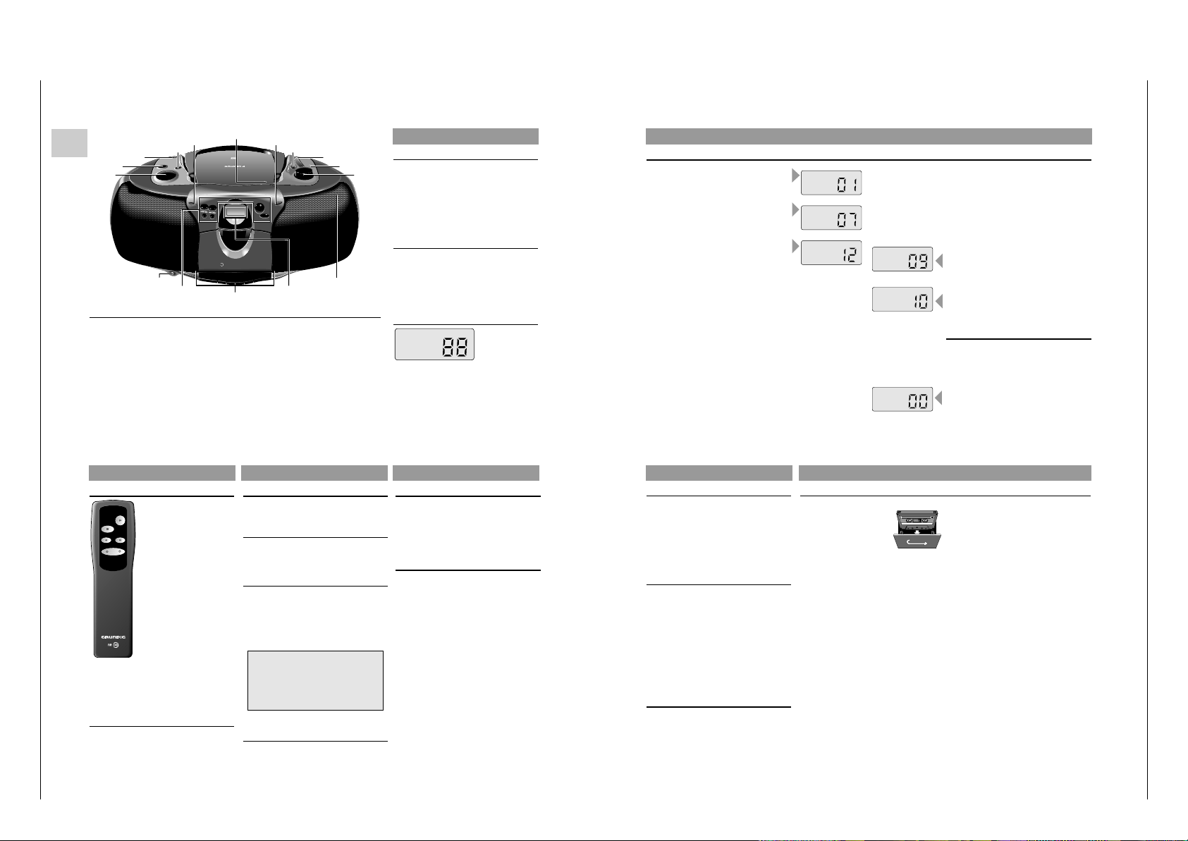
GB
Operating Instructions
Note: This chapter contains excerpts from the operating instructions. For further particulars please refer to the appropriate user instructions the part number of which is indicated in the relevant spare
parts list.
CONTROLS
CD Control
SKIP/SEARCH
∞/56/§ – to skip and search
backward/forward
REPEAT – to repeat one/all tracks
PROG. – to programme track numbers
in the memory
PLAY/PAUSE 2; – to start and interrupt playback
STOP 9 – to stop playback
Cassette Control
0 – to start recording
B – to start cassette playback
Q – fast rewind
R – fast forward
9// – to stop and eject the cassette
; –
to interrupt playback/recording
CD Display
PROGRAM: programme playback
PLAY: PLAY
PAUSE: PAUSE
REPEAT 1: repeat one
REPEAT: repeat all
REPEATPROGRAM
PLAY
PAUSE
1
Top and front panel
(the illustration shows: RR 650 CD)
VOLUME – to adjust the volume
UBS – to switch the ULTRA BASS SYSTEM on and off
FUNCTION – CD: to switch to CD mode / Power On
– TAPE/OFF: to switch to TAPE mode / Power Off
– RADIO: to switch to RADIO mode / Power On
SURROUND SOUND – to switch the surround sound effect on and off
(only RR 650 CD)
REMOTE SENSOR – to receive the remote signals
(only RR 650 CD)
OPEN/CLOSE – to open the CD door
POWER 6 – lights up when the unit is on
BAND – to select between FM, MW, and LW waveband
SCALE – tuning dial scale
FM STEREO
6 – lights up when receiving FM stereo stations
TUNING – to tune to a radio station
MIC – microphone under the speaker grill
p – connection for headphones
C
D
S
Y
N
C
H
ROST
ARTR
E
C
O
R
D
I
N
G
R
R
6
5
0
C
D
R
A
D
I
O
C
A
S
S
ETTER
E
C
O
R
D
E
R
W
I
T
H
C
D
OPEN/
CLOSE
TUNING
MW
LW
FM
SKIP / SEARCH
REPEAT PROG.
PLAY PAUSE
STOP
POWER
REMOTE
SENSOR
PLAYBACK/
RECORD
2
REMOTE
CONTROL
R
R
6
5
0
C
D
RADIO
CASSE
T
T
E
R
E
C
O
R
D
E
R
W
IT
H
C
D
kHz
1600
1400
1200
1000
100
140
120
100
FM
STEREO
C
D
TA
P
E
R
AD
IO
/O
F
F
ULTRA BASS SYSTEM
UBS
SURROUND
SOU
ND
VO
LU
M
E
M
IN
VOLUME
UBS
FUNCTION
SURROUND
SOUND
REMOTE
SENSOR
OPEN/CLOSE
SCALE
BAND
TUNING
FM STEREO 6
CD Display
p
MIC
CD Control
Cassette Control
POWER 6
CONTROLS
Remote control (only RR 650 CD)
Changing the batteries
If the range of your infrared
remote control seems to
decrease, or if certain individual
functions can no longer be
carried out, you should replace
the batteries.
Two mignon 1.5 Volt LR03 size
AAA are required.
To change the batteries, open
the compartment on the back of
the remote control. Ensure that
the batteries are inserted properly
(note the markings in the
compartment).
And in the interest of the
environment: Remember that
batteries must always be
disposed of properly.
PLAY 2 – to start and interrupt CD playback
STOP 9 – to stop CD playback
PREV. ¡ – to skip and search backward
NEXT ™ – to skip and search forward
– VOLUME + – to adjust the volume
Back panel
FM MONO/STEREO / BEAT CUT:
– When BAND switch is in FM:
to select between FM STEREO and FM MONO
– When BAND switch is in MW/LW:
for eliminating possible whistle tones during
MW/LW recordings
AC MAINS: Socket for mains lead.
STOP
PREV.
NEXT
PLAY
VOLUME
SOUND CONTROL
Volume
• Adjust the volume to the desired level with the
VOLUME control.
UBS (Ultra Bass System)
• Press UBS to enhance the bass response:
w UBS OFF
x UBS ON
Surround Sound
(only RR 650 CD)
This feature creates an additional 3-D effect from
stereo sound which is relayed by the speakers.
• Press SURROUND SOUND to switch this effect
on and off
w SURROUND SOUND OFF
x SURROUND SOUND ON
Stereo headphone socket p
• You may connect stereo headphones having a
3.5 mm plug to the jack p.
– Inserting the plug will disconnect the speakers.
Note:
The sound controls can be used with radio,
CD or cassette playback.
However, they have no effect on cassette
recording.
RADIO
Radio aerials
– For FM, pull out the telescopic aerial. To improve
FM-reception, incline and turn the aerial. Reduce
its length if the FM-signal is too strong (very close
to a transmitter).
– For MW/LW, the set is provided with a built-in
aerial, so the telescopic aerial is not needed.
Direct the aerial by turning the whole set.
Radio reception
• Set the FUNCTION switch to RADIO.
– The POWER indicator 6 lights up.
• Adjust the sound using the VOLUME, UBS and
SURROUND SOUND
(only RR 650 CD)
controls.
• You may connect stereo headphones having a
3.5 mm plug to the jack p.
– Inserting the plug will disconnect the speakers.
• Select the wave band using the BAND selector.
• Tune to a desired radio station using the
TUNING control.
– When FM STEREO
6 appears, you are
receiving a FM stereo transmitter.
• A disturbing noise, due to a weak FM stereo
signal, can be suppressed by setting
FM MONO/STEREO to FM MONO.
– The FM STEREO indication
6 goes out and you
will hear the FM station in mono.
• The set is switched off when the FUNCTION
switch is in the TAPE position and no buttons are
pressed.
–The POWER indicator 6 goes out.
CD PLAYER
• Press PLAY/PAUSE 2; to start playback.
– The display shows 'PLAY' and the track number.
• Adjust the sound using the VOLUME, UBS and
SURROUND SOUND
(only RR 650 CD)
controls.
• For brief interruptions, press PLAY/PAUSE 2;.
– 'PAUSE' appears on the display.
• To resume playback, press PLAY/PAUSE 2;
again.
• To stop playback, press STOP 9.
– The total number of tracks will then appear on
the display.
– The CD player also goes to position STOP:
– by pressing OPEN/CLOSE;
– when the end of the CD is reached;
– if the batteries run down or if the power supply
is interrupted.
• To take out the CD, open the CD door by pressing OPEN/CLOSE.
• Open the CD door only if the CD-player is in
position STOP.
Selecting another track during play
• Press ∞/5 or 6/§ until the required track
number appears in the display.
– The selected track begins to play.
Starting with a particular track
• Press ∞/5 or 6/§ until the required track
number appears in the display.
• Press PLAY/PAUSE 2;.
– Play starts from the selected track.
Searching for a passage during play
• Hold ∞/5 down to search backwards to the
beginning.
•
Hold 6/§ down to search forwards to the end.
Note:
This function can be described as “audibly”
searching for a title.
During the search, volume is reduced and returns to
its adjusted level as soon as the button is released.
Repeating a track
• By pressing REPEAT once, one track is repeated.
– The display shows: 'REPEAT 1'
Repeating the CD
• By pressing REPEAT once more, all tracks are
repeated.
– The display shows: 'REPEAT'
• To switch the repeat mode off, press REPEAT
one more time.
Programming
By programming the player you can play up to 21
tracks in any desired order. If you exceed the
maximum of 21 tracks, the programme function will
start again from the beginning.
Storing a programme
• In STOP mode, press PROG..
The display will show '00'.
• Select the first desired track using ∞/5 or
6/§.
• Store this track by pressing PROG. again.
• Select and store in this way all desired titles.
REPEAT
PLAY
REPEAT
1
PLAY
PAUSE
PLAY
PLAY
Playing a CD
CD PLAYER
Checking the programme
• From the STOP position, press PROG.
repeatedly: the display shows in sequence all
programmed track numbers.
Adding tracks to the programme
• Press PROG. repeatedly until the display shows
'00'.
• You can now add tracks to the sequence as
described above (up to 21).
Playing a programme
• Press PROG. once to show the first track of the
programme.
• Press PLAY/PAUSE 2;.
– Play starts with the first track of the programme.
– The display shows 'PROGRAM PLAY'
– After the last track playback stops.
– The total number of tracks will then appear on
the display.
Note:
• Press STOP 9 to stop playback.
• While playing a programme, it is possible to use
∞/5 or 6/§ to select the desired
programmed tracks.
Erasing a programme
• Press STOP 9 to stop playback.
• You can then erase the programme:
– by opening the CD door using OPEN/CLOSE;
– if you move the FUNCTION selector;
– if the batteries are exhausted or if the power
supply is interrupted in another way.
CASSETTE DECK
• Press 9// to open the cassette holder.
• Insert the cassette.
• When monitoring during
recording, adjust the sound
using the controls VOLUME,
UBS and SURROUND
SOUND
(only RR 650 CD)
.
These controls do not affect the recording.
• Start recording by pressing 0.
(the B button is automatically also pressed).
– When the end of the tape is reached, the
recorder buttons are released.
• To interrupt recording, press ;.
• To continue recording, press ; again.
• Press 9// if you want to stop recording before
the end of the tape.
On pressing again, the cassette holder will
open.
• The set is switched off if the FUNCTION switch
is in position TAPE and no buttons are pressed.
– The POWER indicator
6 goes out.
Recording from the CD-player
(CD synchro recording)
• Set the FUNCTION switch to CD.
• It’s not necessary to start the CD player separately: by pressing 0 the CD player starts
automatically.
– If the CD player is in STOP position, recording
will start from the beginning of the CD (or from
the beginning of the programmed selection).
• To start a recording in the middle of a track,
play the CD in the normal way.
• As soon as the desired passage is reached,
pause the CD and then start recording by
pressing 0.
Recording from the radio
• Set the FUNCTION selector to RADIO.
• Select the wave band using the BAND switch.
• Tune to desired radio station using the
TUNING control knob.
• In case of FM radio recordings, set the
FM MONO/STEREO switch to the desired
position.
• If during the recording of an MW/LW station,
a whistling sound is heard, this sound can be
suppressed by setting the BEAT CUT switch to
another position.
Mono recording from the built-in microphone
• Set the FUNCTION switch to TAPE
• Set the VOLUME control to the minimum
volume level (during microphone recording ,
monitoring is not possible).
• To ensure a clear recording, the distance to
microphone should be 30 – 100 cm.
Cassette recording
Page 6
Allgemeiner Teil / General Section RR 620 CD / RR 650 CD
Ausbauhinweise
Allgemeines zum mechanischen Teil.
Alle Schrauben, die in Kunststoff eingedreht werden, sollten zuerst
soweit gegen den Uhrzeigersinn gedreht werden, bis Sie merken, die
Schraube hat den Gewindeanfang gefunden. Erst dann ist die Schraube festzudrehen. Dadurch wird vermieden, daß ein neues Gewinde in
den Kunststoff geschnitten wird und der Halt der Schraube verlorengeht.
Ist es erforderlich, lackgesicherte Schrauben zu lösen, müssen diese
nach Abschluß der Reparatur wieder verlackt werden.
Magnetische Werkzeuge dürfen nicht in die Nähe der Magnetköpfe
gebracht werden.
Nach jeder Reparatur am Cassettenlaufwerk sind die Köpfe, die
Tonwelle und die Andruckrolle mit Spiritus oder Reinigungsbenzin zu
reinigen.
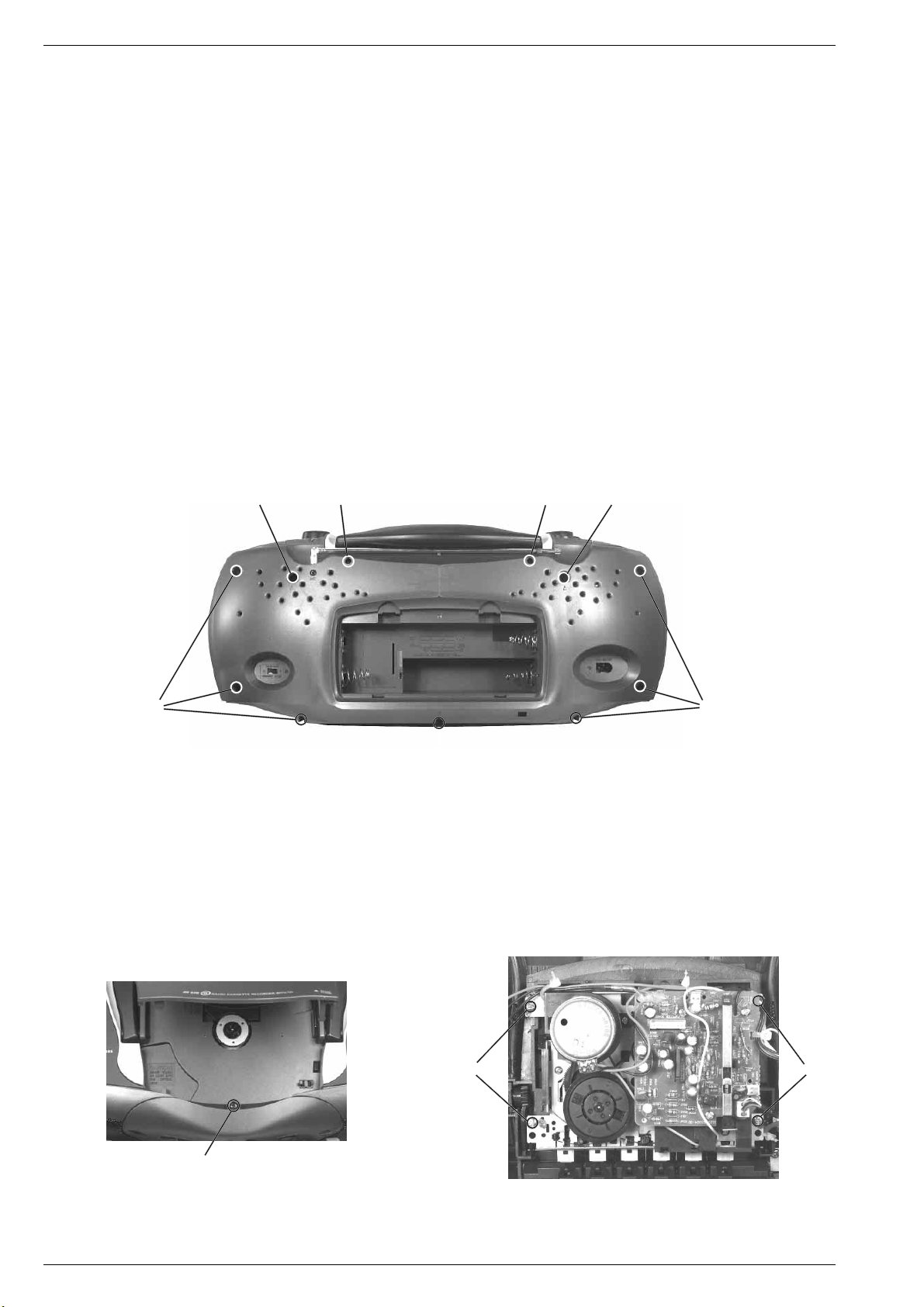
1. Gehäusevorderteil abnehmen
- 2 Schrauben A (lang) und 7 Schrauben B (kurz) herausdrehen
(Fig. 1).
- Schraube C im CD-Fach (Fig. 2) herausdrehen.
- Gehäusevorderteil nach vorne abnehmen.
- Bei Bedarf Steckverbindungen abziehen.
AA
F
Disassembly Instructions
General Notes on the Mechanical Section.
All the screws which are screwed into plastic parts should be turned
counter clockwise first until you notice that the screw has found the first
thread. Then tighten the screw. This preventive measure ensures that
no new threads are cut into the plastic material thus deteriorating the
good fit of the screw.
If screws secured with lacquer have to be loosened, they must be
resecured in the same manner when the repair is completed.
Magnetic tools shall not be brought near the magnetic heads.
Each time repair work has been carried out on the cassette drive
mechanism, clean the heads, the capstan and the rubber pinch roller
with spirit or cleaning benzine.
1. Removing the Cabinet Front
- Undo 2 screws A (long) and 7 screws B (short) (Fig. 1).
- Undo the screw C in the CD compartment (Fig. 2).
- Remove the front of the cabinet towards the front.
- Disconnect the plug-in connections if necessary.
F
B
2. Cass.-Laufwerk ausbauen, (Fig. 3)
- Gehäusevorderteil abnehmen (siehe Pkt. 1).
- 4 Schrauben D herausdrehen.
- Cassettenfachdeckel durch Drücken der Taste STOP/EJECT
öffnen.
- Laufwerk herausnehmen.
- Eventuell Kabelbinder lösen.
B
B
Fig. 1
2. Dismantling the Cassette Drive Mechanism, (Fig. 3)
- Remove the cabinet front (see para 1).
- Undo 4 screws D.
- Open cassette compartment lid by pressing the buttton STOP/
EJECT.
- Take out the cassette drive mechanism.
- Eventually loosen the cable ties.
DD
C
Fig. 3Fig. 2
1 - 6 GRUNDIG Service
Page 7
RR 620 CD / RR 650 CD Allgemeiner Teil / General Section
H
J
I
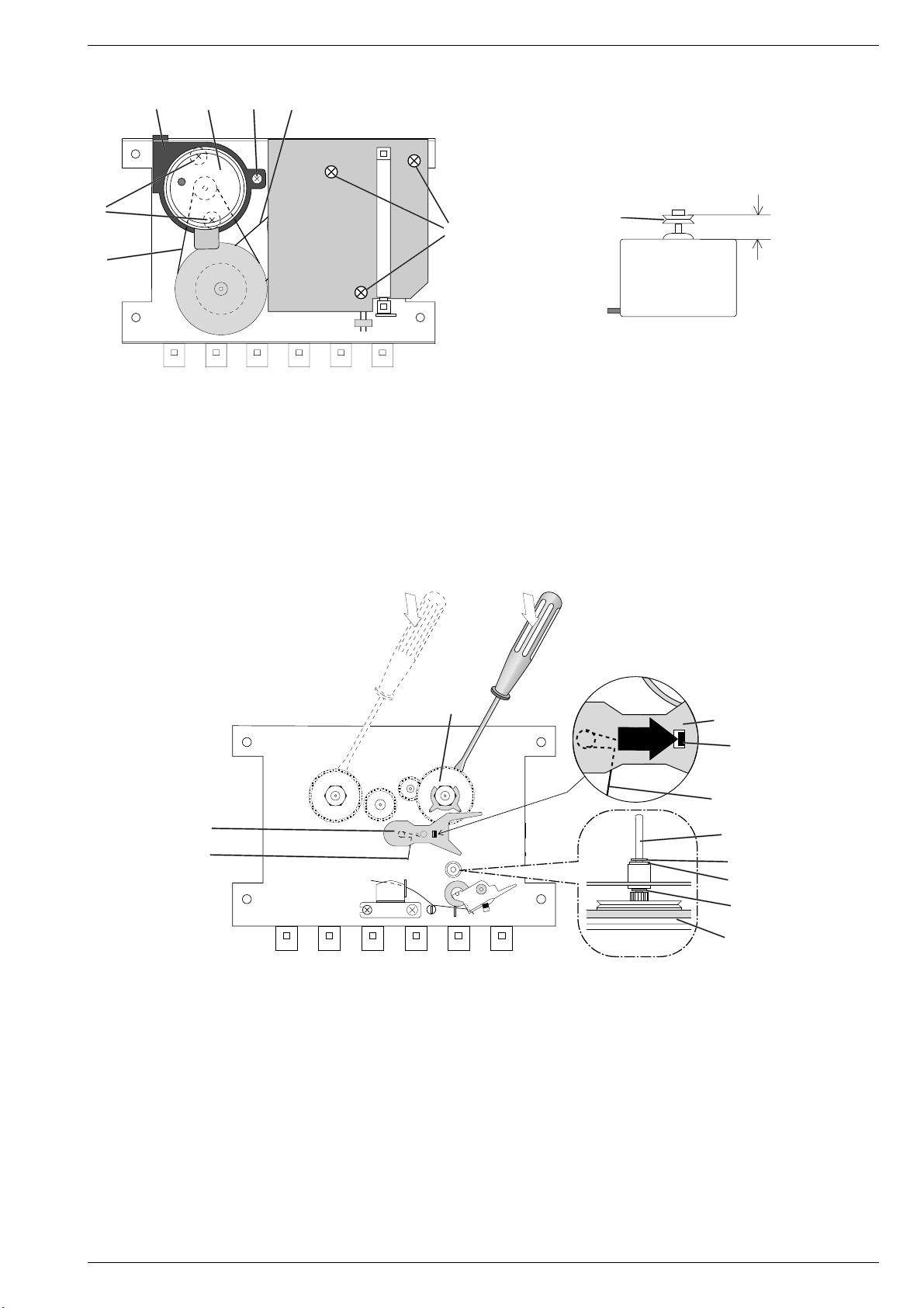
3. Motor ausbauen, (Fig. 4 und 5)
- Laufwerk ausbauen (siehe Pkt. 2).
- Schraube G herausdrehen.
- Motorhalter H (mit Motor) und Riemen I abnehmen.
- Zwei Schrauben J herausdrehen, Motor K (Einbaulage beachten)
abnehmen und Motorzuleitungen ablöten (evtl. markieren).
- Vor dem Zusammenbau ist der Abstand zwischen der Oberkante
der Riemenscheibe L und dem Motor K zu überprüfen (Fig. 5).
K
G
Fig. 4
M
CASS. PCB
START
SWITCH
E
R/P SWITCH
L
MOTOR
7,6 mm
K
Fig. 5
3. Removing the Motor, (Figs. 4 and 5)
- Remove the drive mechanism (see para 2).
- Undo the screw G.
- Remove the motor holder H (with the motor) and the belt I.
- Undo two screws J , take out the motor K (note the motor mounting
position) and unsolder the motor connecting leads (mark them, if
necessary).
- Before refitting the motor, check the distance between the upper
edge of the pulley L and the motor K (Fig. 5).
U
S
T
4. Schwungscheibe ausbauen
- Laufwerk ausbauen (siehe Pkt. 2).
- 3 Schrauben E (Fig. 4) herausdrehen und CASS. PCB abnehmen.
- Riemen M und I abnehmen (Fig. 4).
- Sperrscheibe N (Fig. 6) von der Tonwellenachse abziehen.
- Schwungscheibe O mit der Tonwelle aus dem Schwungscheibenlager herausnehmen. Achten Sie dabei auf die beiden Scheiben P
und Q (Fig. 6).
- Neue Schwungscheibe einsetzen, danach Tonwelle mit Spiritus
reinigen und in umgekehrter Reihenfolge zusammenbauen.
5. Vorlauf-Wickelteller ausbauen (Fig. 6)
- Laufwerk ausbauen (siehe Pkt. 2).
- Rastnase R in Pfeilrichtung A drücken und Hebel S abnehmen,
achten Sie dabei auf die Schenkelfeder T.
- Vorlauf-Wickelteller U mit einem Schraubendreher abhebeln.
S
A
R
T
O
N
Q
P
O
Fig. 6
4. Removing the Flywheel
- Remove the drive mechanism (see para 2).
- Undo 3 screws E (Fig. 4) and remove the CASS. PCB.
- Remove the drive belts M and I (Fig. 4).
- Remove the locking disc N (Fig. 6) from the capstan.
- Remove flywheel O complete with capstan from flywheel bearing.
Take care of the two washers P and Q (Fig. 6).
- Fit new flywheel, clean capstan in white spirit and reassemble in
reverse order.
5. Dismantling of Spool Carrier -forward wind- (Fig. 6)
- Remove the drive mechanism (see para 2).
- Push the catch R in the direction of arrow A and take off lever S,
take care of leg spring T.
- Lift off the spool carrier U (forward wind) by means of a screw driver.
GRUNDIG Service 1 - 7
Page 8
Allgemeiner Teil / General Section RR 620 CD / RR 650 CD
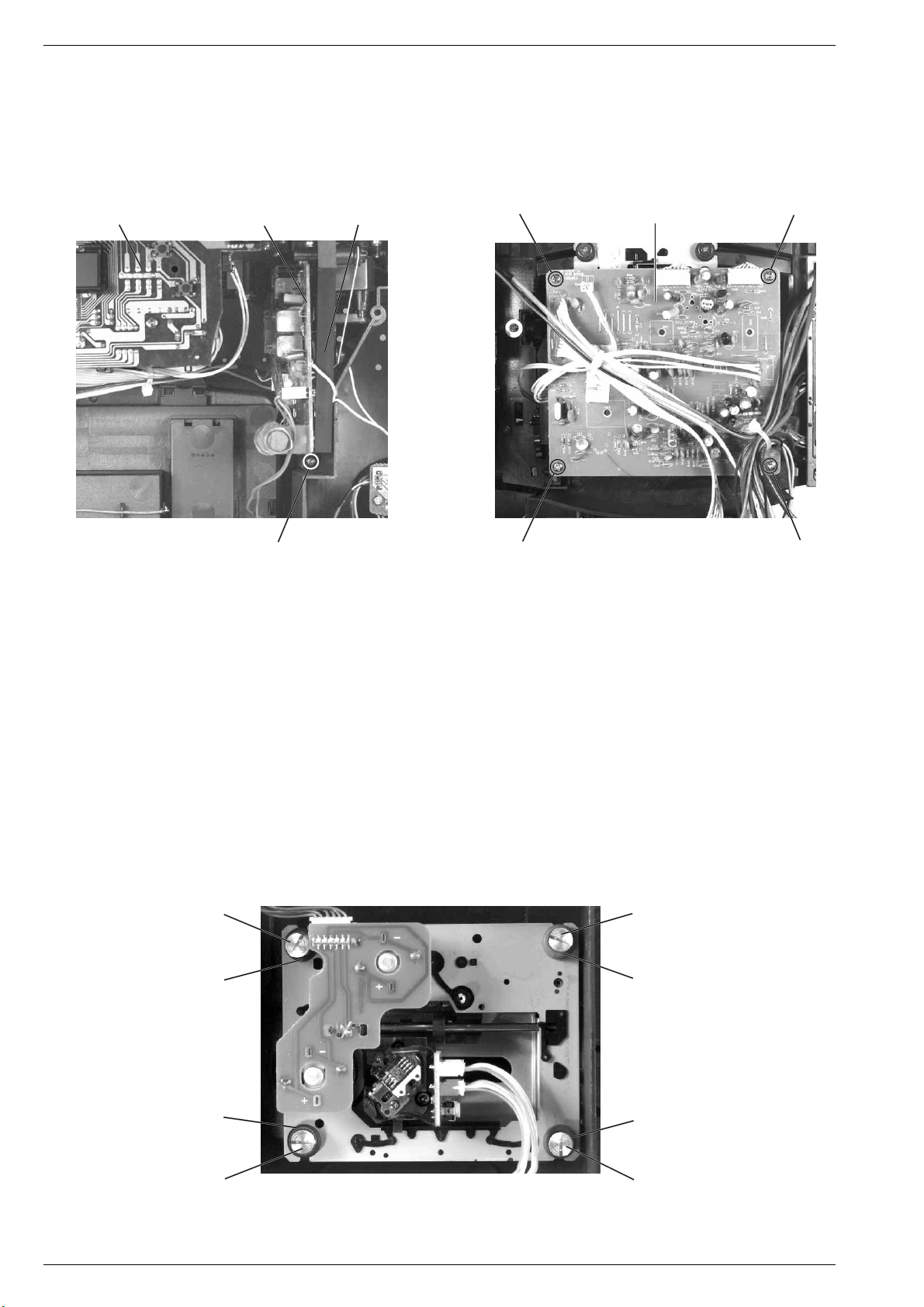
6. Chassis ausbauen, (Fig. 1 und 7)
- Gehäusevorderteil abnehmen, (siehe Pkt. 1).
- 2 Schrauben F herausdrehen (Fig. 1).
- Schraube V herausdrehen (Fig. 7).
- Chassis (mit Lautstärkereglerplatte, Tunerplatte, Bedienplatte, CDTeil) nach vorne herausnehmen.
- Bei Bedarf Steckverbindungen abziehen.
Bedienplatte
Control PCB
Tunerplatte
Tuner PCB
Chassisrahmen
Chassis frame
6. Removing the Chassis, (Fig. 1 and 7)
- Remove the cabinet front (see para 1).
- Undo 2 screws F (Fig. 1).
- Undo the screw V (Fig. 7).
- Remove the chassis towards the front (with volume control PCB,
tuner PCB, control PCB, CD unit).
- Disconnect the plug-in connections if necessary.
aa
CD-Leiterplatte
CD PCB
V
Fig. 7 Fig. 8
7. CD-Laufwerk ausbauen
Bei Ausbau der CD-Lasereinheit muß vor Abziehen der Steckver-
bindungen eine Schutzlötstelle n auf der Leiterplatte der Lasereinheit angebracht werden, um eine Zerstörung der Laserdiode
durch statische Aufladung zu vermeiden (Fig. 13).
- Chassis ausbauen (siehe Pkt. 6).
- 4 Schrauben a (Fig. 8) herausdrehen.
- Steckverbindungen von der CD-Leiterplatte abziehen.
- CD-Leiterplatte abnehmen.
- 4 Schrauben b herausdrehen (Fig. 9).
- CD-Laufwerk herausnehmen.
Achten Sie dabei auf die Puffer (Fig. 9) c (schwarz) und d (blau)
Diese Puffer haben einen unterschiedlichen Auflagedruck
(schwarz = stärker, blau = schwächer).
b
c
a
7. Removing the CD Mechanism
When removing the Laser pick-up, the pick-up PCB must be provided
with a protective soldered joint n before unplugging the connectors to avoid damage to the Laser diode by static charges (Fig. 13).
- Remove the chassis (see para 6).
- Undo 4 screws a (Fig. 8).
- Unplug the connectors from the CD circuit board.
- Take out the CD circuit board.
- Undo 4 screws b (Fig. 9).
- Remove the CD mechanism.
Take care of the buffers c (black) and d (blue) Fig. 9. The buffer
pressure is different (black = stronger, blue = weaker).
a
b
d
c
b
Fig. 9
1 - 8 GRUNDIG Service
d
b
Page 9

RR 620 CD / RR 650 CD Allgemeiner Teil / General Section
o
o
8. Lasereinheit ausbauen
- CD-Laufwerk ausbauen (siehe Pkt. 7).
- 4 Schrauben o herausdrehen und Abdeckblech p abnehmen
(Fig. 10).
- Sperre q vorsichtig in Pfeilrichtung 1 drücken (Fig. 11).
- Führungsstange r in Pfeilrichtung 2 schieben und Lasereinheit
abnehmen (Fig. 12).
1
p
o
o
Fig. 10
8. Removing the Laser Pick-Up
- Remove the CD drive mechanism (see para 7).
- Undo 4 screws o and remove the cover plate p (Fig. 10).
- Push the locking device q carefully in the direction of the arrow 1
(Fig. 11).
- Move the guide rail r in the direction of arrow 2 and remove the
laser pick-up (Fig. 12).
2
q
Fig. 11 Fig. 12
Achtung beim Einbau einer neuen Lasereinheit:
Die Laserdiode ist gegen statische Aufladung beim Transport kurzgeschlossen. Nach dem Einbau und Anschluß der Lasereinheit muß
die Kurzschlußlötstelle n (Fig. 13) auf der Laseranschlußplatte
aufgelötet werden.
Verstellen Sie nicht den Regler für die Laserstromeinstellung!
Der Laserstrom wurde werkseitig eingestellt.
n
r
Attention when fitting the new pick-up:
The laser diode is short-circuited for protection against static charges
during transportation. After fitting the laser unit the soldered short
circuit n (Fig. 13) on the laser connection board must be opened.
Do not turn the variable resistor (laser power adjustment).
The laser current is pre-set at the factory.
Laseranschlußplatte
Laser PCB
Fig. 13
GRUNDIG Service 1 - 9
Page 10

Einstellvorschriften / Adjustment Procedures RR 620 CD / RR 650 CD
j
Einstellvorschriften
1. CD-Teil
Meßgeräte/Meßmittel: Oszilloskop
Hinweis: Verstellen Sie nicht den Regler für die Laserstromeinstellung! Der Laserstrom wurde werkseitig eingestellt.
Abgleichlageplan siehe Seite 2 - 3.
Abgleich Vorbereitung Abgleichvorgang
Focus Offset
Oszilloskop an Meßpunkt TP4 (RF oder IC101 Pin31),
Masse an TP2 (VC oder IC101 Pin48).
- CD einlegen
- CD-Fachdeckel schließen
- CD-Funktion: Play
Mit RV101 einen sauberen Kurvenverlauf (Augenmuster)
einstellen.
2. Cassettenteil
Meßgeräte/Meßmittel: Frequenzzähler, NF-Voltmeter, Tonhöhenschwankungsmesser,
Fe-Testcassette 449 (Sach-Nr. 35079-019.00), Drehmomentcassette 456 (Sach-Nr. 35079-014.00).
Abgleichlageplan siehe Seite 2 - 3.
Abgleich Vorbereitung Abgleichvorgang
1. Bandgeschwindigkeit
2. Aufwickelmoment bei Start
Frequenzzähler an Kopfhörerbuchse.
Testcassette 449 einlegen, 3150Hz abspielen.
Drehmomentcassette 456 einlegen.
Funktion: Wiedergabe-Start.
Mit dem Einstellregler (im Cass.-Motor)
3150Hz ±0,1% einstellen.
Bandzug bei:
Wiedergabe-Start = 35 - 65g-cm
Schnellvorlauf = 50 - 120g-cm
Schnellrücklauf = 50 - 120g-cm
> 1Vss
MOTOR
3. Gleichlauf
4. Kopfspaltsenkrechtstellung
(Azimut)
5. Vormagnetisierungsfrequenz
6. Vormagnetisierungsspannung
Tonhöhenschwankungsmesser an Kopfhörerbuchse.
Testcassette 449 einlegen, 3150Hz abspielen.
NF-Voltmeter an Kopfhörerbuchse.
Testcassette 449 einlegen,
8kHz abspielen.
Frequenzzähler an TP6 (A/W-Kopf).
Bespielbare Cassette einlegen.
Gerätefunktion: Aufnahme-Start.
NF-Voltmeter über einen kapazitiven Spannungsteiler
1:1000 an TP6 (A/W-Kopf).
Bespielbare Cassette einlegen.
Gerätefunktion: Aufnahme-Start.
Gleichlaufabweichung < 0,35% (gehörrichtig bewertet).
Wiedergabemeßzeit ≥ 30 Sekunden.
Mit der Kopfeinstellschraube 1
den linken und rechten Kanal auf
Pegelmaximum einstellen.
Der Pegelunterschied von Kanal zu
Kanal darf maximal 3dB betragen.
Oszillatorfrequenz 60kHz ± 10kHz.
Die Vormagnetisierungsspannung beträgt ca. 10V
(gemessen mit einem kapazitiven Spannungsteiler 1:1000).
1
2 - 1 GRUNDIG Service
Page 11

RR 620 CD / RR 650 CD Einstellvorschriften / Adjustment Procedures
3. Tuner
Meßgeräte: Meßsender, Wobbelsender, Oszilloskop, Frequenzzähler.
Funktionsschalter: Radio
Abgleichlageplan siehe Seite 2 - 3.
Abgleich Vorbereitung Abgleichvorgang
1. AM-ZF
2. MW Oszillator
3. MW Vorkreis
4. LW Oszillator
5. LW Vorkreis
Wobbelsender 465kHz über Rahmenantenne in Ferrit-
antenne einkoppeln.
Oszilloskop an Kopfhörerbuchse.
Bandschalter: MW
Drehkoanschlag: MW fu 526,5kHz, fo 1606,5kHz
Meßsendersignal über Rahmenantenne in Ferritanten-
ne einkoppeln (f
Oszilloskop an Kopfhörerbuchse.
= 1kHz, m = 30%).
mod
Bandschalter: MW
MW 610kHz, MW 1400kHz
Meßsendersignal über Rahmenantenne in Ferritanten-
ne einkoppeln (f
Oszilloskop an Kopfhörerbuchse.
= 1kHz, m = 30%).
mod
Bandschalter: MW
Drehkoanschlag: LW fu 148,5kHz, fo 283,5kHz
Meßsendersignal über Rahmenantenne in Ferritanten-
ne einkoppeln (f
Oszilloskop an Kopfhörerbuchse.
= 1kHz, m = 30%).
mod
Bandschalter: LW
LW 160kHz, LW 280kHz
Meßsendersignal über Rahmenantenne in Ferritanten-
ne einkoppeln (f
Oszilloskop an Kopfhörerbuchse.
= 1kHz, m = 30%).
mod
Bandschalter: LW
Mit T302 auf Maximum einstellen.
fu (bei 526,5kHz) mit T305 auf Maximum einstellen.
fo (bei 1606,5kHz) mit TC4 auf Maximum einstellen.
Abgleich wechselseitig wiederholen.
Bei 610kHz mit MW-Antennenspule auf Maximum einstellen.
Bei 1400kHz mit TC3 auf Maximum einstellen.
Abgleich wechselseitig wiederholen.
fu (bei 148,5kHz) mit T304 auf Maximum einstellen.
fo (bei 283,5kHz) mit TC302 auf Maximum einstellen.
Abgleich wechselseitig wiederholen.
Bei 160kHz mit LW-Antennenspule auf Maximum einstellen.
Bei 280kHz mit TC301 auf Maximum einstellen.
Abgleich wechselseitig wiederholen.
6. FM-ZF
7. FM Oszillator
8. FM Vorkreis
9. FM-MPX (Stereo)
Wobbelsender 10,7MHz an Meßpunkt TP3 (FM-Ant.).
Oszilloskop an Meßpunkt TP2 (IC302, Pin9).
Bandschalter: FM
Drehkoanschlag: FM fu 87,5MHz, fo 108MHz
Meßsendersignal an TP3 (FM-Ant.),
(f
= 1kHz, ∆f = 22,5kHz).
mod
Oszilloskop an Kopfhörerbuchse.
Bandschalter: FM
FM 90MHz, FM 106MHz
Meßsendersignal an Meßpunkt TP3 (FM-Ant.),
(f
= 1kHz, ∆f = 22,5kHz).
mod
Oszilloskop an Kopfhörerbuchse.
Bandschalter: FM
Meßsendersignal 98MHz, unmod. an TP3 (FM-Ant.).
Frequenzzähler an TP5.
Bandschalter: FM
Mit T301 und T303 auf Maximum und Symmetrie einstellen.
Abgleich wechselseitig wiederholen.
fu (bei 87,5MHz) mit L303 auf Maximum einstellen.
fo (bei 108MHz) mit TC1 auf Maximum einstellen.
Abgleich wechselseitig wiederholen.
Bei 90MHz mit L302 auf Maximum einstellen.
Bei 106MHz mit TC2 auf Maximum einstellen.
Abgleich wechselseitig wiederholen.
Mit VR301 76kHz ± 100Hz einstellen.
GRUNDIG Service 2 - 2
Page 12

Einstellvorschriften / Adjustment Procedures RR 620 CD / RR 650 CD
Abgleichlagepläne
Alignment Schemes
Tuner
CD
Cassette
TP6
2 - 3 GRUNDIG Service
Page 13

RR 620 CD / RR 650 CD Einstellvorschriften / Adjustment Procedures
k
Adjustment Procedures
1. CD-Section
Measuring instruments: Oscilloscope
Note: Do not turn the variable resistor (laser power adjustment). The laser current is pre-set at the factory.
Alignment scheme see page 2 - 3.
Adjustment Preparations Adjustment Processs
Focus Offset
Connect the Oscilloscope to testpoint TP4 (RF or Pin31
of IC101), ground to TP2 (VC or Pin 48 of IC101).
- Load a CD
- Close the CD door
- CD Function: PLAY
Adjust RV101 to obtain a clear eye pattern as shown in the
diagram.
2. Cassette Deck
Measuring instruments/equipment: Frequency counter, AF-voltmeter, wow and flutter meter,
Fe test cassette 449 (Part No. 35079-019.00), torque test cassette 456 (Part No. 35079-014.00).
Alignment scheme see page 2 - 3.
Adjustment Preparations Adjustment Process
1. Tape speed
Connect the frequency counter to the headphone socket.
Insert the test cassette 449, play 3150Hz.
With adjustment control (in the
cass.-motor) set the frequency
to 3150Hz ±0.1%.
> 1Vss
MOTOR
2. Take-up torque on
Start
3. Wow and flutter
4. Head gap angle
(Azimuth)
5. Bias frequency
6. Bias voltage
Insert the torque test cassette 456.
Function: Playback-Start.
Connect the wow and flutter meter to the headphone
socket. Insert test cassette 449, play 3150Hz.
Connect the AF-voltmeter to the headphone socket.
Insert test cassette 449,
play 8kHz.
Connect the frequency counter to TP6 (R/P head).
Insert a recordable cassette.
Function: Record-Start.
Connect the AF-voltmeter via a 1:1000 capacitive voltage
divider to TP6 (R/P head). Insert a recordable cassette.
Function: Record-Start
Tape tension on: Playback-Start = 35 - 65g-cm
Deviation < 0.35% (aurally compensated). Playback
measuring time ≥ 30 seconds.
With the head adjustment screw 1 set the
left and right channel to maximum level.
The levels of the two channels mustnot
differ by more than 3dB.
The oscillator frequency should be 60kHz ± 10kHz.
The bias voltage is approx. 10V (measured with a 1:1000
capacitive voltage divider).
Fast Forward = 50 - 120g-cm
Fast Rewind = 50 - 120g-cm
1
GRUNDIG Service 2 - 4
Page 14

Einstellvorschriften / Adjustment Procedures RR 620 CD / RR 650 CD
3. Tuner
Measuring instruments: Signal Generator, Sweep Generator, Oscilloscope, Frequncy Counter.
Function switch: Radio
Alignment scheme see page 2 - 3.
Adjustment Preparations Adjustment Process
1. AM IF
2. MW Oscillator
3. MW Aerial
bandpass
4. LW Oscillator
5. LW Aerial
bandpass
Couple in a sweep signal of 465kHz to ferrite aerial via a
loop aerial.
Oscilloscope to the headphone socket.
Band switch: MW
Var. capacitor to limit stop: MW fu 526.5kHz, fo 1606.5kHz
Couple in a standard signal to ferrite aerial via a loop
aerial, (f
Oscilloscope to the headphone socket.
= 1kHz, m = 30%).
mod
Band switch: MW
MW 610kHz, MW 1400kHz
Couple in a standard signal to ferrite aerial via a loop
aerial, (f
Oscilloscope to the headphone socket.
= 1kHz, m = 30%).
mod
Band switch: MW
Var. capacitor to limit stop: LW fu 148.5kHz, fo 283.5kHz
Couple in a standard signal to ferrite aerial via a loop
aerial, (f
Oscilloscope to the headphone socket.
= 1kHz, m = 30%).
mod
Band switch: LW
LW 160kHz, LW 280kHz
Couple in a standard signal at to ferrite aerial via a loop
aerial, (f
Oscilloscope to the headphone socket.
= 1kHz, m = 30%).
mod
Band switch: LW
Adjust T302 to maximum.
At fu (526.5kHz) adjust to maximum with T305.
At fo (1606.5kHz) adjust to maximum with TC4.
Repeat this adjustment.
At 610kHz adjust to maximum with MW antenna coil.
At 1400kHz adjust to maximum with TC3.
Repeat this adjustment.
At fu (148.5kHz) adjust to maximum with T304.
At fo (283.5kHz) adjust to maximum with TC302.
Repeat this adjustment.
At 160kHz adjust to maximum with LW antenna coil.
At 280kHz adjust to maximum with TC301.
Repeat this adjustment.
6. FM IF
7. FM Oscillator
8. FM Aerial
bandpass
9. FM MPX (Stereo)
Feed in a 10.7MHz sweep signal to TP3 (FM ant.).
Oscilloscope to TP2 (IC302, Pin9).
Band switch: FM
Var. capacitor to limit stop: FM fu 87.5MHz, fo 108MHz
Couple in a standard signal to TP3 (FM ant.),
(f
= 1kHz, ∆f = 22.5kHz).
mod
Oscilloscope to the headphone socket.
Band switch: FM
FM 90MHz, FM 106MHz
Couple in the standard signal to TP3 (FM ant.),
(f
= 1kHz, ∆f = 22.5kHz).
mod
Oscilloscope to the headphone socket.
Band switch: FM
Couple in a standard signal of 98MHz, unmodulated to
TP3 (FM ant.).
Frequency counter to TP5.
Band switch: FM
With T301 and T303 adjust to maximum and symmetry.
At fu (87.5MHz) adjust to maximum with L303.
At fo (108MHz) adjust to maximum with TC1.
Repeat this adjustment.
At 90MHz adjust to maximum with L302.
At 106MHz adjust to maximum with TC2.
Repeat this adjustment.
Set the frequency to 76kHz ± 100Hz with VR301.
2 - 5 GRUNDIG Service
Page 15

RR 620 CD / RR 650 CD Schaltpläne und Druckplattenabbildungen / Circuit Diagrams and Layout of PCBs RR 620 CD / RR 650 CD Schaltpläne und Druckplattenabbildungen / Circuit Diagrams and Layout of PCBs
Schaltpläne und Druckplattenabbildungen / Circuit Diagrams and Layout of PCBs
Verdrahtungsplan / Wiring Diagram
- +
+ -
R/P HEAD
TRAFO
AC SOCKET
CASSETTE BOARD
R G L
•
AF / POWER BOARD
4
4
+ -
•
CN601
•
CN606
CN607
CN602
CN603
CONDENSOR
•
•
MIC
2
2
AC
AC
+12V
GND
2
BEAT CUT
BOARD
8
FUSE BOARD
FM ANTENNA
TUNER BOARD
•
CN301
2
CONTROL BOARD
(LCD DISPLAY)
5
3
CN105
CN208
CD MAIN BOARD
•
3
7
CN210
CN203
•
6
•
8
CN104
3
•
•
2
TONE CONTROL BOARD
CN404
(VOLUME)
CN401
CN408
CN103
CN203
CN403
CN405
•
•
6
CN102 CN101
8
•
•
8
LASER HEAD
BOARD
CN106
CN202
2
CD DOOR
SWITCH
CN609
CN406
•
CN608
2
CN604
•
•
CN605
•
3
•
CN402
5
to CD Motor Board
BEI DEN IN DEN SCHALTPLÄNEN ANGEGEBENEN MESSWERTEN HANDELT ES SICH UM NÄHERUNGSWERTE!
THE MEASURED VALUES GIVEN IN THE CIRCUIT DIAGRAMS ARE APPROXIMATES!
GRUNDIG Service GRUNDIG Service3 - 1 3 - 2
Page 16

Schaltpläne und Druckplattenabbildungen / Circuit Diagrams and Layout of PCBs RR 620 CD / RR 650 CD Schaltpläne und Druckplattenabbildungen / Circuit Diagrams and Layout of PCBs RR 620 CD / RR 650 CD
Tuner
Seite / page
3 - 5
Seite / page
3 - 13
TA 8164 P
AM
RM INFMRF OUT
16 15 14 13 12 11 10 9
FM
RF
1 2345678
RF IN
AM / FMSWFM
FM / AM
SW
FM MIX AM MIX AGC
MIX
FM
GND1FM
OSC
MIX
AM
OSC
AGCAM
DET
OUT
AM DET
V
CC
Seilzug
Dial cord
QUAD GND2
FM DETAM OSCFM OSC
AM
IF
FM
IF INAMIF IN
3 x
GLEICHSPANNUNGEN GEGEN GND i GEMESSEN.
DC-VOLTAGES MEASURED AGAINST GND i.
VOLTAGES IC U302 TA7343
PIN 123456789
V (FM) 3.5 5.0 6.5 5.6 0 5.8 5.8 3.5 3.5
V (AM) 3.3 5.0 6.5 4.7 0 5.0 6.4 3.5 3.5
VOLTAGES IC U301 TA8164P
PIN 12345678910111213141516
V (FM) 0.8 0 6.4 6.4 5.0 6.4 6.4 6.4 0 6.4 1.6 5.7 6.4 6.4 6.4 0.3
V (AM) 2.2 0 7.0 7.0 9.0 7.0 7.0 7.0 0 7.0 1.6 7.0 0.7 0.7 7.0 7.0
TA 7343
AF DC VCO 76kHz
1
INPUT
FM
IF
PHASE DET.
PILOT DET.
STEREO
DECODER
89
OUTPUT
LPF
(1)
2
VCO
19 kHz < 90
TRIGGER
19 kHz < 0
38 kHz
7
LPF
(2)
4
°
°
STEREO
LED
1/2 1/2
STEREO
SWITCH
6
1/2
STABILIZED
POWER SUPPLY
3
5
GND*VccLR
108MHz
GRUNDIG Service GRUNDIG Service3 - 3 3 - 4
Pointer
Page 17

RR 620 CD / RR 650 CD Schaltpläne und Druckplattenabbildungen / Circuit Diagrams and Layout of PCBs RR 620 CD / RR 650 CD Schaltpläne und Druckplattenabbildungen / Circuit Diagrams and Layout of PCBs
BA 3313 L
ALC
INPUT 1 INPUT 2OUTPUT 1
OUTPUT 2ALC
GND
FILTERVCC
1 3 5 7 9 11
2 4 6 8
+
-
+
-
10 12
NF 2NF 1
GND
(SUB)N.C.
Cassette
Seite / page
3 - 4
CN501
Seite / page
3 - 6
CN502
( V ) = REC.
STEREO SW
(6.6V)
(-1.4V)
BEAT CUT
(0.5V)
CASSETTE
x
Seite / page
3 - 16
2.0V
0.75V
0.1V
Seite / page
3 - 13
C
E
B
CN502
Seite / page
3 - 5
GLEICHSPANNUNGEN GEGEN GND i GEMESSEN.
DC-VOLTAGES MEASURED AGAINST GND i.
VOLTAGES IC U501 BA3313L
PIN 123456789101112
V
(REC) 2.6 0.3 0.6 0 0.1 0 0 6.2 0.1 6.2 0.6 2.6
V (PLAY) 2.9 0 0.6 0 0 0 0 6.8 0 6.8 0.6 2.9
B
C
E
Seite / page
3 - 5
CN502
GRUNDIG Service GRUNDIG Service3 - 5 3 - 6
Page 18

Schaltpläne und Druckplattenabbildungen / Circuit Diagrams and Layout of PCBs RR 620 CD / RR 650 CD Schaltpläne und Druckplattenabbildungen / Circuit Diagrams and Layout of PCBs RR 620 CD / RR 650 CD
CD
3 2 1
Seite / page
3 - 9
C
B
E
1
1
1
1
Seite / page
3 - 9
CN202
Seite / page
3 - 11
CN203
E
B
C
E
B
C
Seite / page
3 - 13
Seite / page
3 - 9
Seite / page
3 - 15
GRUNDIG Service GRUNDIG Service3 - 7 3 - 8
GLEICHSPANNUNGEN BEI "PLAY" GEGEN MASSE (GND) GEMESSEN.
DC-VOLTAGES MEASURED AGAINST MINUS TERMINAL (GND) ON "PLAY".
Page 19

RR 620 CD / RR 650 CD Schaltpläne und Druckplattenabbildungen / Circuit Diagrams and Layout of PCBs RR 620 CD / RR 650 CD Schaltpläne und Druckplattenabbildungen / Circuit Diagrams and Layout of PCBs
VOLTAGES IC101 CXA1782
PIN V PIN V PIN V PIN V
37
1
2
3
4
5
6
7
8
9
10
11
12
2.5
2.5
2.5
2.5
2.5
2.5
2.8
2.5
2.5
0.8
2.5
2.5
14
2.5
15
2.5
16
1.2
17
18
19
20
3.3
21
N.C.
22
0.05
23
4.6
24
2.5
13
2.5
5
25
38
0.5
26
39
0.6
27
28
29
5
30
5
31
8
32
33
34
35
36
1.4
2.4
2.4
3.5
2.5
3.7
0.2
2.5
2.5
N.C.
40
41
42
43
44
45
46
47
48
VOLTAGES IC102 KA9258D
PIN V PIN V
2.5
15
3.5
1
2
3
N.C.
4
5
6
7
8
N.C.
9
10
11
12
13
14
3.6
2.5
2.5
3.6
3.6
2.4
2.5
16
4
17
3.1
18
N.C.
19
7
2.5
20
5
7.7
21
5
7.7.
22
0
2.5
23
N.C.
24
2.5
25
3.6
26
3.6
27
0
0
28
2.4
2.5
2.5
2.5
2.4
2.5
2.3
2.5
2.5
2.5
VOLTAGES IC103 CXD2508Q
PIN V PIN V PIN V PIN V
N.C.
65
N.C.
2.5
25
0.05
1
N.C.
2
0
3
0
0
4
4.8
5
0.01
6
3.8
7
4.8
8
3.3
9
4.8
10
4.8
11
0
12
3.8
13
0.05
14
3.3
15
5
16
5
17
5
18
5
19
N.C.
20
N.C.
21
0.04
22
5
23
N.C.
24
41
N.C.
66
2.5
N.C.
26
42
2.5
N.C.
27
43
2.5
0
28
44
2.5
2.2
29
45
2.4
2.6
30
46
2.4
2.6
31
47
N.C.
5
32
48
N.C.
0
33
49
N.C.
2.2
34
50
5
35
51
N.C.
2.5
36
52
0.8
37
53
N.C.
2.5
38
54
N.C.
2.5
39
55
N.C.
5
40
56
N.C.
57
N.C.
58
N.C.
59
N.C.
60
N.C.
61
N.C.
62
63
N.C.
64
0
67
5
68
2.5
69
2.4
70
5
71
5
72
2.5
73
2.5
74
0
75
5
0
76
2.4
77
0
2.5
78
0
79
0
80
-
Schaltbilder Lasereinheit
Circuit Diagrams Laser Pick up
LASER HEAD BOARD
FOCUS
TRACK
Drehtellermotor
Turn Table Motor
Schlittenmotor
Sled Motor
LD
GND
PD
TO
VR
FCSTRK-
TRK+
FCS+
CN102
PAGE
3 - 7
CD MOTOR BOARD
+
-
+
-
Innen-Schalter
Inner Switch
SP+
SP-
SL+
SLL.SW
L.SW
TO
CN103
PAGE
3 - 7
GND
D
C
B
TO
A
CN101
PAGE
3 - 7
K
E
F
GRUNDIG Service GRUNDIG Service3 - 9 3 - 10
Page 20

Schaltpläne und Druckplattenabbildungen / Circuit Diagrams and Layout of PCBs RR 620 CD / RR 650 CD Schaltpläne und Druckplattenabbildungen / Circuit Diagrams and Layout of PCBs RR 620 CD / RR 650 CD
Bedienteil / Control Board
POWER LED
LED 201
IR-SENSOR
2.6V
3.4V
1.8V
0.2V
2.3V
2.1V
F-SKIP R-SKIP
PROG. REPEAT
2.6V
2.6V
2.6V
2.6V
2.6V
2.6V
2.6V
2.6V
C
PLAY/PAUSE
E
E
C
C
B
STOP
E
C
E
B
B
B
C
E
E
C
B
B
1
2.6V
5V
5V
5V
0V
5V
5V
5V
5V
0V
CN208
Seite / page
3 - 8
5V
5V
5V
5V
5V
5V
5V
5V
5V
5V
5V
0.1V
4.4V
5V
5V
4.4V
0V
CN203
CN210
CN210
CN210
GLEICHSPANNUNGEN BEI FUNKTION CD-"STOP" GEGEN MASSE (GND) GEMESSEN.
DC-VOLTAGES MEASURED AGAINST MINUS TERMINAL (GND) ON FUNCTION CD-"STOP".
Seite / page
3 - 15
GRUNDIG Service GRUNDIG Service3 - 11 3 - 12
Page 21

RR 620 CD / RR 650 CD Schaltpläne und Druckplattenabbildungen / Circuit Diagrams and Layout of PCBs RR 620 CD / RR 650 CD Schaltpläne und Druckplattenabbildungen / Circuit Diagrams and Layout of PCBs
Klangregelung / Tone Control
3.1V
2.1V
1.5V
CN403
Seite / page
3 - 5
Seite / page
3 - 4
Seite / page
3 - 16
Seite / page
3 - 8
CN401
CN405
CN408
2.1V
3.1V
1.5V
0.6V
0.6V
0.9V
0.9V
Seite / page
3 - 16
CN402
Seite / page
3 - 16
CN404
CN406
Seite / page
3 - 16
GRUNDIG Service GRUNDIG Service3 - 13 3 - 14
Page 22

Schaltpläne und Druckplattenabbildungen / Circuit Diagrams and Layout of PCBs RR 620 CD / RR 650 CD Schaltpläne und Druckplattenabbildungen / Circuit Diagrams and Layout of PCBs RR 620 CD / RR 650 CD
NF-Teil und Stromversorgung / AF Part and Power Supply
Seite / page
3 - 7
Seite / page
3 - 11 / 3 - 12
Seite / page 3 - 13
3 - 13
Seite / page
x
3 - 13
3 - 5
Seite / page
Seite / page
RR 620 CD: Alle Bauteile in Block A nicht bestückt,
J601 + J602 geschlossen
RR 650 CD: Alle Bauteile in Block A bestückt,
J601 + J602 geöffnet
RR 620 CD: Omit all components in Block A,
connect J601 + J602
RR 650 CD: Put all components in Block A,
omit J601 + J602
3 - 13
Seite / page
GRUNDIG Service GRUNDIG Service3 - 15 3 - 16
Page 23

RR 620 CD / RR 650 CD Schaltpläne und Druckplattenabbildungen / Circuit Diagrams and Layout of PCBs RR 620 CD / RR 650 CD Schaltpläne und Druckplattenabbildungen / Circuit Diagrams and Layout of PCBs
Netzteil / NF-Platte
Power Supply / AF Board
B C E
Sicherungsplatte / Fuse Board
B C E
1
B
C
E
E
C
B
1
B
B
2
3
1
C
E
B
C
C
E
E
GRUNDIG Service GRUNDIG Service3 - 17 3 - 18
Page 24

RR 620 CD / RR 650 CD Ersatzteillisten und Explosionszeichnungen / Spare Parts Lists and Exploded Views
107
10
8
9
6
7
5
4
3
2
1
67
69
70
68
71
72
74
75
73
76
22
21
20
18
17
14
13
15
16
12
11
19
58
60
62
61
63
65
64
66
59
81
80
82
83
40
38
39
37
36
35
34
32
33
31
28
27
29
30
25
24
23
41
43
44
42
46
47
48
50
49
51
52
53
54
55
56
57
92
45
94
88
87
90
86
84
85
93
26
91
89
79
77
78
100
101
95
109
96
108
103
102
99
98
97
104
106
105
D
POS. NR.
ABB.
SACHNUMMER ANZ.
POS. NO.
FIG.
PART NUMBER QTY.
BEZEICHNUNG
DESCRIPTION
D
GB
BEZEICHNUNG
DESCRIPTION
SACHNUMMER
PART NUMBER
POS. NR.
POS. NO.
BEZEICHNUNG
DESCRIPTION
SACHNUMMER
PART NUMBER
POS. NR.
POS. NO.
Ersatzteillisten und Explosionszeichnungen / Spare Parts Lists and Exploded Views
Explosionszeichnung RR 620 CD / Exploded View RR 620 CD
1
RR 620 CD / RR 650 CD Ersatzteillisten und Explosionszeichnungen / Spare Parts Lists and Exploded Views
Ersatzteilliste
MICROPHONE
LED 301 8309-944-406 LE DIODE TLHR 4405 TFK
MIC 001 75954-046.18 MIKROFON KOND. KUC 4023/
Q 101 75954-046.19 TRANSISTOR SS 9012G
Q 102 75954-046.19 TRANSISTOR SS 9012G
Q 103 75954-046.20 TRANSISTOR SS 9015C
Q 201 75952-500.06 TRANS.9014 C
Q 202 75952-500.06 TRANS.9014 C
Q 203 75952-500.06 TRANS.9014 C
Q 204 75952-500.06 TRANS.9014 C
C 609 75954-046.01 ELKO 2200 MFD 25V +/-20%
C 615 8452-995-104 ELKO 1000UF 20% 16V
C 618 8452-995-104 ELKO 1000UF 20% 16V
C 805 75954-010.28 ELKO 1000UF 25V +-20%
CF 202 75954-046.02 KER.-RESONATOR ZTA 2.00M
CF 301 75954-046.03 KER.-RESONATOR LPU465B
CF 302 72878-700.01 KERAMIK-FILTER SFE 10,7
D 201 8309-215-045 DIODE 1N4148
D 202 8309-215-045 DIODE 1N4148
D 301 8309-215-045 DIODE 1N4148
#
75.3119-1051
32700
*
Btx
G.DG 6151
RR 620 CD
SACH-NR. / PART NO.:
BESTELL-NR. / ORDER NO.:
Spare Parts List
Q 205 75954-046.15 TRANS. 9012F
Q 206 75952-500.06 TRANS.9014 C
Q 401 75952-500.06 TRANS.9014 C
Q 402 75952-500.06 TRANS.9014 C
Q 403 75952-500.06 TRANS.9014 C
Q 404 75952-500.06 TRANS.9014 C
D 302 8309-215-045 DIODE 1N4148
D 303 75954-046.04 DIODE AFC 1S 2638
D 304 8309-215-045 DIODE 1N4148
D 601 8309-215-020 DIODE 1 N 4004 -GA
D 602 8309-215-020 DIODE 1 N 4004 -GA
D 603 8309-215-045 DIODE 1N4148
Q 501 75952-500.06 TRANS.9014 C
Q 503 75985-267.00 TRANS.2 SC 2001
Q 601 75954-046.21 TRANSISTOR 8050 B
Q 602 75952-500.06 TRANS.9014 C
Q 603 75952-500.06 TRANS.9014 C
Q 604 75952-500.06 TRANS.9014 C
D 604 8309-215-045 DIODE 1N4148
D 605 8309-215-045 DIODE 1N4148
D 606 8309-215-045 DIODE 1N4148
D 607 8309-215-045 DIODE 1N4148
D 608 8309-215-045 DIODE 1N4148
D 609 8309-215-045 DIODE 1N4148
Q 605 75952-500.06 TRANS.9014 C
Q 606 75952-500.06 TRANS.9014 C
SW 301 75954-046.23 TAKTSCHALTER SL.SW SKT
SW 402 75954-046.24 TAKTSCHALTER PUSH SW. PSA
SW 403 75954-046.24 TAKTSCHALTER PUSH SW. PSA
SW 405 75954-021.14 TAKTSCHALTER
SW 406 75954-021.14 TAKTSCHALTER
D 610 8309-215-045 DIODE 1N4148
D 611 8309-215-045 DIODE 1N4148
D 612 8309-215-045 DIODE 1N4148
D 613 8309-215-020 DIODE 1 N 4004 -GA
D 801 8309-215-020 DIODE 1 N 4004 -GA
D 802 8309-215-020 DIODE 1 N 4004 -GA
D 803 8309-215-020 DIODE 1 N 4004 -GA
D 804 8309-215-020 DIODE 1 N 4004 -GA
SWITCH
SW 501 75954-035.84 SCHALTER 9P2T
SW 502 75954-046.25 TAKTSCHALTER SL SW SS22F
SWCDDR 75954-021.04 SCHALTER
SWCDKEY 75954-021.14 TAKTSCHALTER/
T 301 75954-046.26 FILTER 7A 240 OHM
T 302 75954-046.27 FILTER 4A 222 OHM
T 303 75954-046.28 FILTER 7A 161 OHM
T 304 75954-046.29 FILTER 1A 451 OHM
8315-619-003 SI 5X20 T1,6A L 250V
S
DZ 601 75981-314.31 Z DIODE 8,2V
DZ 602 8309-720-055 Z DIODE 5,6 B 0,5W
F 801
IC 101 75954-021.21 SMD-IC CXA 17820Q
IC 102 75954-046.06 IC KA 9258 D
WW. 75954-021.24 IC BA 6398 FP
IC 103 75954-046.07 IC CXD 2508AQ
75954-046.31 TRAFO AC 48X24/TRANSFORMER
S
T 305 75954-046.30 FILTER 1A 405 OHM
TAC 001
TC 301 75954-046.32 TRIMMER 40PF 2 LEGS
TC 302 75954-046.32 TRIMMER 40PF 2 LEGS
VC 301 75954-046.33 DREKKO PVC FAT 16B2C (R1)
VR 101 75954-021.79 REGLER KVSF637 AB 50 KOHM/
IC 104 75954-046.08 IC KA 4558N
WW. 75952-504.33 IC BA 4558
IC 201 75954-046.05 IC CXP 1042Q
ICU 301 75954-021.13 IC TA 8164 P
ICU 302 75987-438.29 IC TA 7343 AP
ICU 501 75954-046.09 IC BA 3313L
ICU 601 75951-045.04 IC MC 7808 BF
ICU 602 75954-046.10 IC KA 22066
ICU 603 75954-046.11 IC BA 5049
ICU 604 75954-046.12 IC BA 5053
CONTROL
CONTROL
VR 301 8790-047-151 ESTR.SK10 10 KOHM
VR 101 75954-020.20 REGLER KVSF637AB 50KOHM/
WW. = WAHLWEISE/OPTIONAL
X 101 75954-020.24 QUARZ 33.8688MHZ
HEADPHONE SOCKET
75954-021.44 NETZ BUCHSE/MAINS SOCKET
S
JAC 001
JHP 001 75954-021.70 KOPFHOERER BUCHSE/
L 101 75954-021.26 SPULE 10 UH 3A 035 N/COIL
L 102 75954-021.26 SPULE 10 UH 3A 035 N/COIL
L 103 75954-021.26 SPULE 10 UH 3A 035 N/COIL
L 303 75954-021.75 SPULE 2-1/2T/COIL
L 501 75954-021.10 DR 560UH RM2 RAD 3A 396N
COIL
L 502 75954-046.16 SPULE 1,5MH CW-152 KOHM/
LLWANT 75954-046.13 SPULE LW (M3) DIA./COIL
LMWANT 75954-046.14 SPULE MW (M1) DIA./COIL
LCD 101 75954-046.17 DISPLAY LCD TCM763
LED 1 8309-944-406 LE DIODE TLHR 4405 TFK
GRUNDIG Service
75987-453.17 NETZKABEL POWER CABLE
72010-747.65 BEDIENUNGSANLEITUNG INSTRUCTION MANUAL
0001.000 1 75954-046.47 ABDECKUNG L COVER L
0002.000 1 75954-046.96 LAUTSPRECHER GITTER L LOUDSPEAKER GRILL L
0003.000 1 75954-046.92 TUER, CASS. DOOR, CASS.
0004.000 1 75954-046.43 LINSE, TUER CASS. LENS, DOOR CASS.
0005.000 1 75954-046.49 FRONTBLENDE FRONT MASK
0006.000 1 75954-046.57 2 LINSE, POWER LENS, POWER
0007.000 1 75954-046.72 KNOPF, SKIP/SEARCH CD KNOB, SKIP/SEARCH CD
0010.000 1 75954-046.38 GEHAEUSEVORDERTEIL CABINET FRONT
0011.000 1 75954-046.58 KNOPF REC, CASS. KNOB REC, CASS.
0012.000 1 75954-046.59 KNOPF PLAY, CASS. KNOB PLAY, CASS.
0013.000 1 75954-046.60 KNOPF REW CASS. KNOB REW CASS.
0014.000 1 75954-046.61 KNOPF FF, CASS. KNOB FF, CASS.
0015.000 1 75954-046.62 KNOPF STOP/EJEKT, CASS. KNOB STOP/EJEKT, CASS.
0016.000 1 75954-046.63 KNOPF PAUSE, CASS. KNOB PAUSE, CASS.
0019.000 1 75954-046.87 CASS LAUFW. TK20FX-S818-003 CASS.DRIVE MECHANISM TK20FX-S818-003
0023.000 1 75954-046.95 VOLUME KNOPF KNOB VOLUME
0024.000 1 75954-046.75 KNOPF UBS KNOB UBS
0025.000 1 75954-046.74 KNOPF, FUNKTIONSCHALTER KNOB, FUNCTION SWITCH
0026.000 1 75954-046.42 CD KONSOLE CD KONSOLE
0028.000 1 75954-046.94 ABDECKBLENDE L MASK COVER L
0030.000 1 75954-046.36 HALTER HOLDER
0031.000 1 75954-046.84 MAGNET MAGNET
0032.000 1 75954-046.78 MAGNETHALTER SOLENOID HOLDER
0033.000 1 75954-046.93 TUER, CD DOOR, CD
0034.000 1 75954-046.46 HALTER, GRIFF L HOLDER, HANDLE L
0035.000 1 75954-046.50 HALTER, GRIFF R HOLDER, HANDLE R
0036.000 1 75954-046.55 GRIFF HANDLE
0038.000 1 75954-046.90 BATTERIE KONTAKT + BATTERY CONTACT +
0040.000 1 75954-046.37 TUER, BATTERIE DOOR, BATTERY
0045.000 1 75954-046.86 TELESKOPANTENNE TELESCOPIC ANTENNA
0046.000 1 75954-046.39 GEHAEUSERUECKTEIL REAR PANEL
0047.000 1 75954-046.91 BATTERIE KONTAKT +/- BATTERY CONTACT +/-
0050.000 1 75954-046.68 ZEIGER POINTER
0051.000 1 75954-046.71 KNOPF, BANDSCHALTER KNOB, BAND SWITCH
0054.000 1 75954-046.65 PULLY PULLEY
0059.000 1 75954-046.66 LINSE DIAL LENS DIAL
0065.000 1 75954-046.89 LAUTSPRECHER 4" 8 OHM LOUDSPEAKER 4" 8 OHM
0067.000 1 75954-046.83 FUSS, GUMMI FOOT, RUBBER
0068.000 1 75954-046.79 FEDER, TUER CASS SPRING, DOOR CASS.
0069.000 1 75954-046.73 KNOPF PLAY/STOP, CD KNOB PLAY/STOP, CD
0070.000 1 75954-046.44 LINSE DISPLAY LENS DISPLAY
0073.000 1 75954-046.54 HALTER B HOLDER B
0074.000 1 75954-046.53 DECKELBREMSE B BRAKE LID B
0075.000 1 75954-046.97 LAUTSPRECHER GITTER R LOUDSPEAKER GRILL R
0076.000 1 75954-046.48 ABDECKUNG R COVER R
0080.000 1 75954-046.88 CD-LAUFWERK CD DRIVE MECHANISM
0087.000 1 75954-046.85 SCHNAEPPER, SCHALTER CATCH SWITCH
0094.000 1 75954-046.52 HALTER A HOLDER A
0095.000 1 75954-046.51 DECKELBREMSE A BRAKE LID A
0096.000 1 75954-046.67 ABDECKBLENDE R MASK COVER R
0100.000 1 75954-046.35 ANDRUCKSCHEIBE B PRESSURE ROLLER B
GRUNDIG Service
9 / 96
0101.000 1 75954-046.70 KNOPF, TUNING KNOB, TUNING
72010-751.70 SERVICE MANUAL D/GB SERVICE MANUAL D/GB
S
0113.000 75954-046.45 FERRITSTAB 10X100mm FERRITE BAR 140X100mm
0105.000 1 75954-046.80 FEDER, CD TUER SPRING, CD DOOR
0112.000
4 - 24 - 1
Page 25

RR 620 CD / RR 650 CD Ersatzteillisten und Explosionszeichnungen / Spare Parts Lists and Exploded Views
40
38
39
37
31
28
27
29
30
25
24
22
23
21
20
18
17
11
10
8
9
6
7
5
4
3
2
19
26
76
1
99
93
41
43
44
42
45
94
36
35
34
32
33
97
96
98
95
46
47
48
50
51
52
53
54
55
92
56
57
58
88
89
90
86
84
85
81
80
82
83
60
62
61
63
65
64
66
59
91
49
79
77
78
14
13
15
16
12
67
69
70
68
71
72
74
75
73
87
106
107
101
100
102
104
103
108
Explosionszeichnung RR 650 CD / Exploded View RR 650 CD
1
GRUNDIG Service 4 - 3
Page 26

4 - 4 GRUNDIG Service
D
POS. NR.
ABB.
SACHNUMMER ANZ.
POS. NO.
FIG.
PART NUMBER QTY.
BEZEICHNUNG
DESCRIPTION
D
GB
POS. NR.
ABB.
SACHNUMMER ANZ.
POS. NO.
FIG.
PART NUMBER QTY.
BEZEICHNUNG
DESCRIPTION
D
GB
BEZEICHNUNG
DESCRIPTION
SACHNUMMER
PART NUMBER
POS. NR.
POS. NO.
BEZEICHNUNG
DESCRIPTION
SACHNUMMER
PART NUMBER
POS. NR.
POS. NO.
Änderungen vorbehalten Printed in Germany Service Manual Sach-Nr.
Subject to alteration VK 231/233 0996 Service Manual Part No. 72010-751.70
9 / 96
0001.000 1 75954-046.77 KNOPF SOUND KNOB SOUND
0002.000 1 75954-046.81 LAUTSPRECHER GITTER L LOUDSPEAKER FRILL L
0003.000 1 75954-046.40 TUER, CASS. DOOR, CASS.
0004.000 1 75954-046.43 LINSE, TUER CASS. LENS, DOOR CASS.
0005.000 1 75954-046.64 FRONTBLENDE FRONT MASK
0006.000 1 75954-046.57 2 LINSE, POWER LENS,POWER
0007.000 1 75954-046.72 KNOPF, SKIP/SEARCH CD KNOB,SKIP/SEARCH CD
0010.000 1 75954-046.38 GEHAEUSEVORDERTEIL CABINET FRONT
0011.000 1 75954-046.58 KNOPF REC, CASS. KNOB REC, CASS.
0012.000 1 75954-046.59 KNOPF PLAY, CASS. KNOB PLAY, CASS.
0013.000 1 75954-046.60 KNOPF REW CASS. KNOB REW CASS.
0014.000 1 75954-046.61 KNOPF FF, CASS. KNOB FF, CASS.
0015.000 1 75954-046.62 KNOPF STOP/EJEKT, CASS. KNOB STOP/EJEKT, CASS.
0016.000 1 75954-046.63 KNOPF PAUSE, CASS. KNOB PAUSE, CASS.
0019.000 1 75954-046.87 CASS LAUFW. TK20FX-S818-003 CASS. DRIVE MECHANISM TK20FX-S818-003
0023.000 1 75954-046.76 KNOPF VOLUME KNOB VOLUME
0024.000 1 75954-046.75 KNOPF UBS KNOB UBS
0025.000 1 75954-046.74 KNOPF, FUNKTIONSCHALTER KNOB FUNCTION SWITCH
0026.000 1 75954-046.42 CD KONSOLE CD KONSOLE
0028.000 1 75954-046.69 ABDECKBLENDE L MASK COVER L
0030.000 1 75954-046.36 HALTER HOLDER
0031.000 1 75954-046.84 MAGNET MAGNET
0032.000 1 75954-046.78 MAGNETHALTER SOLENOID HOLDER
0033.000 1 75954-046.41 TUER, CD DOOR, CD
0034.000 1 75954-046.46 HALTER, GRIFF L HOLDER, HANDLE L
0035.000 1 75954-046.50 HALTER, GRIFF R HOLDER, HANDLE R
0036.000 1 75954-046.55 GRIFF HANDLE
0038.000 1 75954-046.90 BATTERIE KONTAKT + BATTERY CONTACT +
0040.000 1 75954-046.37 TUER, BATTERIE DOOR BATTERY
0045.000 1 75954-046.86 TELESKOPANTENNE TELESCOPIC ANTENNA
0046.000 1 75954-046.39 GEHAEUSERUECKTEIL REAR PANEL
0047.000 1 75954-046.91 BATTERIE KONTAKT +/- BATTERY CONTACT +/-
0050.000 1 75954-046.68 ZEIGER POINTER
0051.000 1 75954-046.71 KNOPF, BANDSCHALTER KNOB, BAND SWITCH
0054.000 1 75954-046.65 PULLY PULLEY
0059.000 1 75954-046.66 LINSE DIAL LENS DIAL
0065.000 1 75954-046.89 LAUTSPRECHER 4" 8 OHM LOUDSPEAKER 4" 8 OHM
0067.000 1 75954-046.83 FUSS, GUMMI FOOT, RUBBER
0068.000 1 75954-046.79 FEDER, TUER CASS SPRING, DOOR CASS.
0069.000 1 75954-046.73 KNOPF PLAY/STOP, CD KNOB PLAY/STOP, CD
0070.000 1 75954-046.44 LINSE DISPLAY LENS DISPLAY
0073.000 1 75954-046.54 HALTER B HOLDER B
0074.000 1 75954-046.53 DECKELBREMSE B BRAKE LID B
0075.000 1 75954-046.82 LAUTSPRECHER GITTER R LOUDSPEAKER GRILL R
0080.000 1 75954-046.88 CD-LAUFWERK CD DRIVE MECHANISM
0082.000 1 75954-021.63 PUFFER CUSHION
0082.100 1 75954-021.64 PUFFER CUSHION
0087.000 1 75954-046.85 SCHNAEPPER, SCHALTER CATCH SWITCH
0092.000 1 75954-046.52 HALTER A HOLDER A
0093.000 1 75954-046.51 DECKELBREMSE A BRAKE LID A
0094.000 1 75954-046.67 ABDECKBLENDE R MASK COVER R
0098.000 1 75954-046.35 ANDRUCKSCHEIBE B PRESSURE ROLLER B
0099.000 1 75954-046.70 KNOPF, TUNING KNOB, TUNING
0103.000 1 75954-046.80 FEDER, CD TUER SPRING, CD DOOR
0110.000 75954-046.34 FERNBEDIENUNG REMOTE CONTROL
0112.000
0113.000 75954-046.45 FERRITSTAB 10X100mm FERRITE BAR 10X100mm
Ersatzteilliste
Spare Parts List
S
75987-453.17 NETZKABEL POWER CABLE
Btx
RR 650 CD
SACH-NR. / PART NO.:
BESTELL-NR. / ORDER NO.:
32700
*
75.3120-1051
G.DG 6251
Ersatzteillisten und Explosionszeichnungen / Spare Parts Lists and Exploded Views RR 620 CD / RR 650 CD
72010-747.70 BEDIENUNGSANLEITUNG INSTRUCTION MANUAL
#
C 609 75954-046.01 ELKO 2200 MFD 25V +/-20%
C 615 8452-995-104 ELKO 1000UF 20% 16V
C 618 8452-995-104 ELKO 1000UF 20% 16V
C 805 75954-010.28 ELKO 1000UF 25V +-20%
CF 202 75954-046.02 KER.-RESONATOR ZTA 2.00M
CF 301 75954-046.03 KER.-RESONATOR LPU465B
CF 302 72878-700.01 KERAMIK-FILTER SFE 10,7
D 201 8309-215-045 DIODE 1N4148
D 202 8309-215-045 DIODE 1N4148
D 301 8309-215-045 DIODE 1N4148
D 302 8309-215-045 DIODE 1N4148
D 303 75954-046.04 DIODE AFC 1S 2638
D 304 8309-215-045 DIODE 1N4148
D 601 8309-215-020 DIODE 1 N 4004 -GA
D 602 8309-215-020 DIODE 1 N 4004 -GA
D 603 8309-215-045 DIODE 1N4148
D 604 8309-215-045 DIODE 1N4148
D 605 8309-215-045 DIODE 1N4148
D 606 8309-215-045 DIODE 1N4148
D 607 8309-215-045 DIODE 1N4148
D 608 8309-215-045 DIODE 1N4148
D 609 8309-215-045 DIODE 1N4148
D 610 8309-215-045 DIODE 1N4148
D 611 8309-215-045 DIODE 1N4148
D 612 8309-215-045 DIODE 1N4148
D 613 8309-215-020 DIODE 1 N 4004 -GA
D 801 8309-215-020 DIODE 1 N 4004 -GA
D 802 8309-215-020 DIODE 1 N 4004 -GA
D 803 8309-215-020 DIODE 1 N 4004 -GA
D 804 8309-215-020 DIODE 1 N 4004 -GA
DZ 601 75981-314.31 Z DIODE 8,2V
DZ 602 8309-720-055 Z DIODE 5,6 B 0,5W
F 801
IC 101 75954-021.21 SMD-IC CXA 17820Q
IC 102 75954-046.06 IC KA 9258 D
WW. 75954-021.24 IC BA 6398 FP
IC 103 75954-046.07 IC CXD 2508AQ
IC 104 75954-046.08 IC KA 4558N
WW. 75952-504.33 IC BA 4558
IC 201 75954-046.05 IC CXP 1042Q
ICU 301 75954-021.13 IC TA 8164 P
ICU 302 75987-438.29 IC TA 7343 AP
ICU 501 75954-046.09 IC BA 3313L
ICU 601 75951-045.04 IC MC 7808 BF
ICU 602 75954-046.10 IC KA 22066
ICU 603 75954-046.11 IC BA 5049
ICU 604 75954-046.12 IC BA 5053
JAC 001
JHP 001 75954-021.70 KOPFHOERER BUCHSE/
L 101 75954-021.26 SPULE 10 UH 3A 035 N/COIL
L 102 75954-021.26 SPULE 10 UH 3A 035 N/COIL
L 103 75954-021.26 SPULE 10 UH 3A 035 N/COIL
L 303 75954-021.75 SPULE 2-1/2T/COIL
L 501 75954-021.10 DR 560UH RM2 RAD 3A 396N
L 502 75954-046.16 SPULE
LLWANT 75954-046.13 SPULE LW (M3) DIA./COIL
LMWANT 75954-046.14 SPULE MW (M1) DIA./COIL
72010-751.70 SERVICE MANUAL D/GB SERVICE MANUAL D/GB
S
8315-619-003 SI 5X20 T1,6A L 250V
S
75954-021.44 NETZ BUCHSE/MAINS SOCKET
HEADPHONE SOCKET
WW. = WAHLWEISE WW. = OPTIONAL
LCD 101 75954-046.17 DISPLAY LCD TCM763
LED 1 8309-944-406 LE DIODE TLHR 4405 TFK
LED 301 8309-944-406 LE DIODE TLHR 4405 TFK
MIC 001 75954-046.18 MIKROFON KOND. KUC 4023/
Q 101 75954-046.19 TRANSISTOR SS 9012G
Q 102 75954-046.19 TRANSISTOR SS 9012G
Q 103 75954-046.20 TRANSISTOR SS 9015C
Q 201 75952-500.06 TRANS.9014 C
Q 202 75952-500.06 TRANS.9014 C
Q 203 75952-500.06 TRANS.9014 C
Q 204 75952-500.06 TRANS.9014 C
Q 205 75954-046.15 TRANS. 9012F
Q 206 75952-500.06 TRANS.9014 C
Q 401 75952-500.06 TRANS.9014 C
Q 402 75952-500.06 TRANS.9014 C
Q 403 75952-500.06 TRANS.9014 C
Q 404 75952-500.06 TRANS.9014 C
Q 501 75952-500.06 TRANS.9014 C
Q 503 75985-267.00 TRANS.2 SC 2001
Q 601 75954-046.21 TRANSISTOR 8050 B
Q 602 75952-500.06 TRANS.9014 C
Q 603 75952-500.06 TRANS.9014 C
Q 604 75952-500.06 TRANS.9014 C
Q 605 75952-500.06 TRANS.9014 C
Q 606 75952-500.06 TRANS.9014 C
RX 001 75954-046.22 EMPFAENGER RPM638BR-L/
SW 301 75954-046.23 TAKTSCHALTER SL.SW SKT
SW 402 75954-046.24 TAKTSCHALTER PUSH SW. PSA
SW 403 75954-046.24 TAKTSCHALTER PUSH SW. PSA
SW 405 75954-021.14 TAKT SCHALTER
SW 406 75954-021.14 TAKT SCHALTER
SW 501 75954-035.84 SCHALTER 9P2T
SW 502 75954-046.25 TAKTSCHALTER SL SW SS22F
SWCDDR 75954-021.04 SCHALTER
SWCDKEY 75954-021.14 TAKT SCHALTER/
T 301 75954-046.26 FILTER 7A 240 OHM
T 302 75954-046.27 FILTER 4A 222 OHM
T 303 75954-046.28 FILTER 7A 161 OHM
T 304 75954-046.29 FILTER 1A 451 OHM
T 305 75954-046.30 FILTER 1A 405 OHM
TAC 001
S
75954-046.31 TRAFO AC 48X24/TRANSFORMER
TC 301 75954-046.32 TRIMMER 40PF 2 LEGS
TC 302 75954-046.32 TRIMMER 40PF 2 LEGS
VC 301 75954-046.33 DREKKO PVC FAT 16B2C (R1)
VR 101 75954-021.79 REGLER KVSF637 AB 50 KOHM/
VR 301 8790-047-151 ESTR.SK10 10 KOHM
VR 101 75954-020.20 REGLER KVSF637AB 50KOHM/
1,5MH CW-152 KOHM/
COIL
X 101 75954-020.24 QUARZ 33.8688MHZ
MICROPHONE
RECEIVER
SWITCH
CONTROL
CONTROL
 Loading...