

Page 1
jj IMPORTANT INFORMATION IMPORTANT INFORMATION jj KEEP FOR OPERATOR KEEP FOR OPERATOR jj IMPORTANT INFORMATION IMPORTANT INFORMATION jj
OPERATOR MANUAL OM-TDB/8-20-CFC
Part Number 121027
MODEL: TDB/8-20-CFC
Water Jacketed Fudge Kettle
Self-Contained
Electrically heated
Table top mounted
Tilting
Power Agitator
THIS MANUAL MUST BE RETAINED FOR FUTURE REFERENCE. READ, UNDERSTAND AND FOLLOW THE INSTRUCTIONS AND WARNINGS CONTAINED IN THIS
MANUAL.
FOR YOUR SAFETY
DO NOT STORE OR USE GASOLINE OR OTHER FLAMMABLE VAPORS AND
LIQUIDS IN THE VICINITY OF THIS OR ANY OTHER APPLIANCE.
Page 2

OM-TDB/8-20-CFC
IMPORTANT — READ FIRST — IMPORTANT
CAUTION: BE SURE ALL OPERATORS READ, UNDERSTAND AND FOLLOW OPERATING
INSTRUCTIONS, CAUTIONS, AND SAFETY INSTRUCTIONS IN THIS MANUAL.
WARNING: THIS UNIT IS INTENDED FOR USE IN THE COMMERCIAL HEATING, COOKING AND
HOLDING OF WATER AND FOOD PRODUCTS, PER THE INSTRUCTIONS
CONTAINED IN THIS MANUAL. ANY OTHER USE COULD RESULT IN PERSONAL
INJURY OR DAMAGE TO THE EQUIPMENT AND WILL VOID WARRANTY.
WARNING: KETTLE MUST BE INSTALLED BY PERSONNEL QUALIFIED TO WORK WITH
ELECTRICITY. IMPROPER INSTALLATION CAN RESULT IN INJURY TO
PERSONNEL AND/OR DAMAGE TO EQUIPMENT.
WARNING: AVOID ALL DIRECT CONTACT WITH HOT EQUIPMENT SURFACES. DIRECT SKIN
CONTACT COULD RESULT IN BURNS.
WARNING: AVOID ALL DIRECT CONTACT WITH HOT FOOD OR WATER IN THE KETTLE.
DIRECT CONTACT COULD RESULT IN BURNS.
CAUTION: DO NOT OVER FILL THE KETTLE WHEN COOKING, HOLDING OR CLEANING.
KEEP LIQUIDS A MINIMUM OF 4- 5” (10-15 cm) BELOW THE KETTLE BODY RIM
TO ALLOW CLEARANCE FOR STIRRING AND SAFE PRODUCT TRANSFER.
WARNING: TAKE SPECIAL CARE TO AVOID CONTACT WITH HOT KETTLE BODY OR HOT
PRODUCT WHEN ADDING INGREDIENTS, STIRRING OR TRANSFERRING
PRODUCT TO ANOTHER CONTAINER.
WARNING: WHEN TILTING KETTLE FOR PRODUCT TRANSFER:
1) WEAR PROTECTIVE OVEN MITT AND PROTECTIVE APRON.
2) USE CONTAINER DEEP ENOUGH TO CONTAIN AND MINIMIZE SPLASHING.
3) PLACE CONTAINER ON STABLE, FLAT SURFACE, AS CLOSE TO KETTLE AS
POSSIBLE.
4) DO NOT STAND IN POUR PATH OF HOT CONTENTS.
5) POUR SLOWLY, MAINTAIN CONTROL OF KETTLE BODY HANDLE AT ALL
TIMES, AND RETURN KETTLE BODY TO UPRIGHT POSITION AFTER
CONTAINER IS FILLED OR TRANSFER IS COMPLETE.
6) DO NOT OVER FILL CONTAINER. AVOID DIRECT SKIN CONTACT WITH HOT
CONTAINER AND ITS CONTENTS.
CAUTION: KEEP FLOORS IN FRONT OF KETTLE WORK AREA CLEAN AND DRY. IF SPILLS
OCCUR, CLEAN IMMEDIATELY, TO AVOID SLIPS OR FALLS.
WARNING: TO AVOID INJURY, READ AND FOLLOW ALL PRECAUTIONS STATED ON THE
LABEL OF THE WATER TREATMENT COMPOUND.
WARNING: BEFORE REPLACING ANY PARTS, DISCONNECT THE ELECTRIC POWER
SUPPLY.
WARNING: KEEP WATER AND SOLUTIONS OUT OF CONTROLS. NEVER SPRAY OR HOSE
THE KETTLE BODY OR ELECTRICAL CONNECTIONS.
CAUTION: MOST CLEANERS ARE HARMFUL TO THE SKIN, EYES, MUCOUS MEMBRANES
AND CLOTHING. TAKE PRECAUTIONS: WEAR RUBBER GLOVES, GOGGLES OR
FACE SHIELD AND PROTECTIVE CLOTHING. CAREFULLY READ THE WARNINGS
AND FOLLOW THE DIRECTIONS ON THE LABEL OF THE CLEANER TO BE USED.
CAUTION: USE OF ANY REPLACEMENT PARTS OTHER THAN THOSE SUPPLIED BY GROEN
OR THEIR AUTHORIZED DISTRIBUTORS CAN CAUSE OPERATOR INJURY AND
DAMAGE TO THE EQUIPMENT, AND WILL VOID ALL WARRANTIES.
IMPORTANT: SERVICE PERFORMED BY OTHER THAN FACTORY AUTHORIZED PERSONNEL
WILL VOID WARRANTIES.
2
Page 3

OM-TDB/8-20-CFC
Table of Contents
IMPORTANT OPERATOR WARNINGS .................................................2
REFERENCES ....................................................................3
EQUIPMENT DESCRIPTION .........................................................4
INSPECTION & UNPACKING .........................................................5
INSTALLATION ....................................................................5
OPERATION ......................................................................6
CLEANING .......................................................................7
MAINTENANCE ...................................................................8
TROUBLESHOOTING .............................................................10
SPECIFICATIONS ................................................................11
PARTS LIST .....................................................................12
ELECTRICAL SCHEMATICS ........................................................16
MAINTENANCE LOG ..............................................................18
WARRANTY .....................................................................19
References
KLENZADE SALES CENTER
ECOLAB. Inc.
370 Wabasha
St. Paul, Minnesota 55102
800/352-5326 or 612/293-2233
NATIONAL FIRE PROTECTION ASSOCIATION
60 Battery March Park
Quincy, Massachusetts 02269
NFPA/70 The National Electrical Code
NATIONAL SANITATION FOUNDATION
3475 Plymouth Rd.
Ann Arbor, Michigan 48106
UNDERWRITERS LABORATORIES, INC.
333 Pfingsten Road
Northbrook, Illinois 60062
ZEP MANUFACTURING CO.
1310-T Seaboard Industrial Blvd.
Atlanta, Georgia 30318
3
Page 4
OM-TDB/8-20-CFC
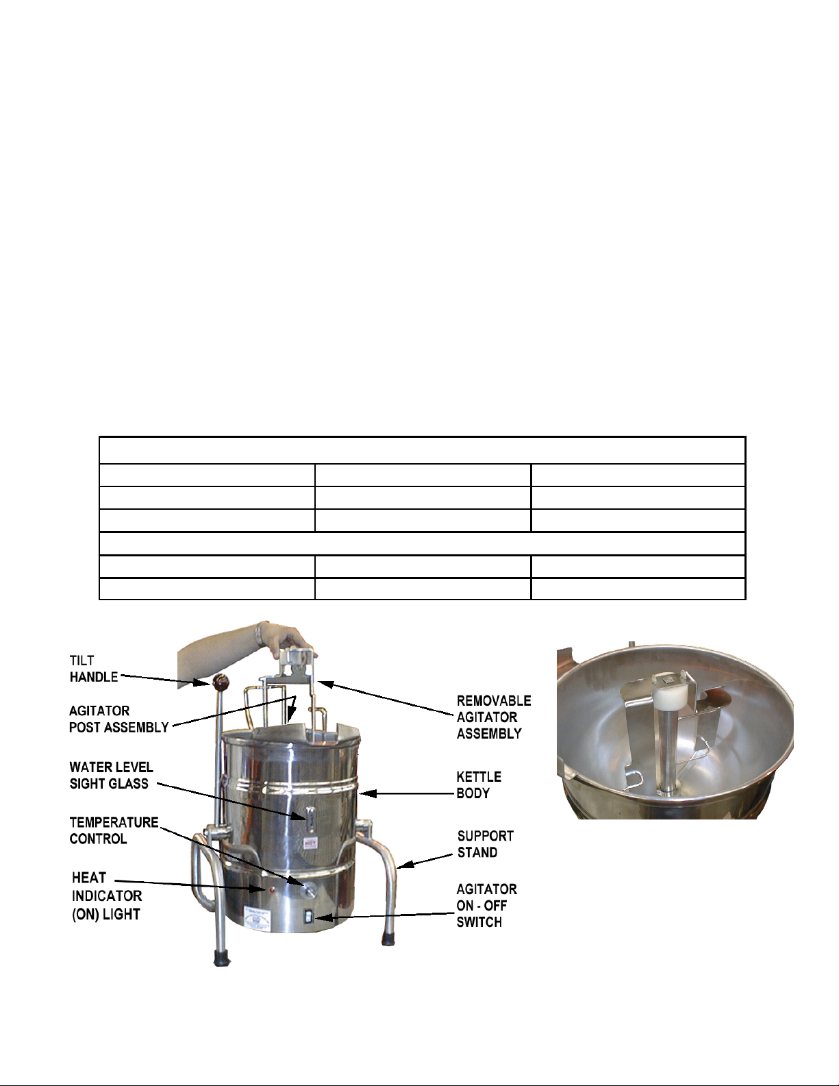
Equipment Description
The Groen TDB/8-20-CFC cooker/mixer consists In addition to the three-stage adjustable
of a water-jacketed kettle with a motor-driven thermostat for operating control, the unit has a
mixer. The 20 quart tilting kettle is equipped with high limit thermostat, as a safety feature, plus an
electronically controlled electric heaters for the indicator lamp and water gauge glass, with which
jacket. to monitor kettle operation.
The kettle of Model TDB/8-20-CFC is Mixing is controlled with a power switch. The
constructed of stainless steel welded into one switch doubles as a circuit breaker for motor
piece. The body has a reinforced rim and a protection. The agitator continuously sweeps the
butterfly-shaped pouring lip. It is fitted with an side and bottom of the kettle.
integral water jacket. The kettle exterior has a
bright semi-deluxe finish. The kettle’s pouring Electric power for the kettle and mixer is
height allows filling pans up to 4 inches high on supplied through a plug-in power cord, which is
a table top. furnished with the unit. Standard unit operation
requires connection to single phase, 115 VAC,
The kettle’s internal electric heaters provide 60 Hz electrical service. The unit must be
uniform heat in three stages, with jacket supplied from a separate, dedicated 20A branch
temperature control over the range of 140 to circuit.
180ºF (60 to 80ºC).
COOKER/MIXER CHARACTERISTICS
Kettle Capacity 20 Quarts 18.8 Liters
Diameter 14 inches 36 cm
Depth 11 Inches 28 cm
SPACE REQUIRED (Approximate)
Side to Side 19 inches 48 cm
Vertical 30 inches 76 cm
The Agitator fits over the agitator
post inside the kettle.
4
Page 5
OM-TDB/8-20-CFC
Inspection & Unpacking
The unit will arrive in a shipping carton which Thoroughly inspect the unit for concealed
has been strapped or stapled shut. Immediately damage. Report any shipping damage or
upon receipt, inspect the carton carefully for incorrect shipments to the delivery agent.
exterior damage.
Write down the model number, serial number,
CAUTION
SHIPPING STRAPS ARE UNDER TENSION
AND CAN SNAP BACK WHEN CUT. TAKE
CARE TO AVOID PERSONAL INJURY OR
DAMAGE TO THE UNIT BY STAPLES
LEFT IN THE WALLS OF THE CARTON.
Carefully cut the straps around the carton and
detach the sides of the box. Pull the carton up
off the unit.
Installation
and installation date, and file this information for
future reference. Space for these entries is
provided at the top of the Service Log on Page
18 of this manual.
When installation is to begin, lift the unit straight
up, obtaining help as needed. Examine packing
materials to be sure loose parts are not
discarded with the materials.
3. Confirm that the jacket water level is at the
middle of the sight glass. If the level is low,
use the following procedure for adding water:
WARNING
IMPROPER INSTALLATION CAN RESULT
IN INJURY TO PERSONNEL AND/OR
DAMAGE TO EQUIPMENT.
THE UNIT MUST BE GROUNDED. DO
NOT FORCE THE PLUG OR ALTER IT TO
OVERRIDE GROUNDING FEATURES.
The Groen cooker/mixer is provided with
complete internal wiring. It is ready for
immediate connection. The completed unit was
operated at the factory to check the controls,
mixer and jacket heater.
Any mechanical or electrical changes must be
approved in by Groen’s Food Service
Engineering Department.
1. Set the kettle in place and level it.
2. Provide electrical power as specified on the
electrical information plate attached to the
equipment. Observe local codes and/or The
National Electrical Code in accordance with
ANSI/NFPA 70 - (current edition).
a. If you are replacing water lost by
evaporation, use distilled water. To
replace treated water that ran out of the
jacket, prepare more treated water as
described in Water Treatment, Page 9.
b. Remove the plug from the elbow.
c. Add water or treated water through the
elbow, until the water level rises to the
middle of the sight glass. Note that
added water must raise the level in the
whole jacket, so a substantial amount of
water will be needed to make a small
change in the level.
d. Replace the plug in the elbow. Follow
instructions under “Jacket Filling and
Water Treatment” in the “Maintenance”
section of this manual.
5
Page 6
OM-TDB/8-20-CFC
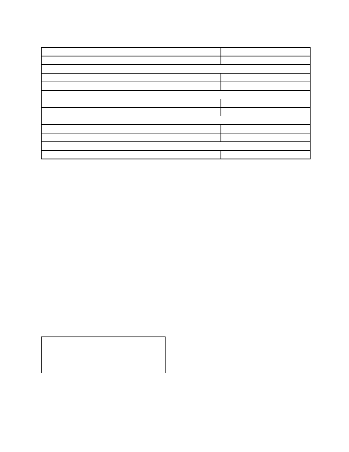
ELECTRICAL CHARACTERISTICS
Frequency 60 Hz 50 Hz
Voltage 120 240
Kettle
Power, KW 1.9 1.9
Draw, AMP 16.5 8.3
Motor
Power, HP 1/4 1/4
Full-load current, AMP 2.5 1.3
Capacitance
Start 25 25
Run 7.5 7.5
Service Power Recommendation
Service suggested 20 AMP, 1 PH 15 AMP, 1 PH
Operation
A. Controls
The operator controls the cooker/mixer with the:
1. Temperature control dial. The dial turns
electric power for the heaters on or off and
sets the operating temperature of the kettle,
with a maximum jacket temperature of
180BF. (Maximum temperature of a product
heated by the kettle is less than 180B, due to
heat loss out the top of the kettle.)
2. Mixer power switch, a switch that turns
electric power for the motor drive on and off.
B. To Operate the Kettle (Heating)
1. Every day make sure that the jacket water
level is at the middle of the sight glass. If the
level is low, see “Jacket Filling” in the
“Maintenance & Cleaning” section of this
manual.
CAUTION
DO NOT OPERATE THE KETTLE WHEN
THE WATER LEVEL IN THE JACKET IS
LOW. YOU MAY BURN OUT THE HEATING
ELEMENTS.
the light on and off indicates that the kettle is
being held at the set temperature. Once in
each cycle the temperature controller will
make a clicking sound as it cycles on and off.
This is normal.
4. To shut down the kettle, turn the temperature
control dial to “OFF.”
5. For prolonged shut-down or before cleaning
the outside of the unit, unplug the unit.
C. To Operate the Mixer
1. Place the agitator on the shaft.
2. Press the power switch to the “ON” position.
3. To shut down the mixer, press the power
switch to “OFF.”
4. For prolonged shut-down or when the outside
of the unit is to be cleaned, unplug the unit.
2. Plug in the power cord. If necessary, turn on
the power at the circuit breaker or fuse box.
3. Turn the temperature control dial to the
desired setting. The red indicator light
indicates that the kettle is heating. Cycling of
6
Page 7

Cleaning
OM-TDB/8-20-CFC
1. Suggested Tools:
a. Cleaner, such as Klenzade HC-10 or
HC-32 from ECOLAB, Inc.
b. Kettle brushes in good condition.
c. Sanitizer such as Klenzade XY-12.
d. Film remover such as Klenzade LC-30. can be used to clean controls and
b. Scrape and flush out food residues. Be
careful not to scratch the kettle with
metal implements.
c. Prepare a hot solution of the detergent/
cleaning compound as instructed by the
supplier. Clean the unit thoroughly. A
cloth moistened with cleaning solution
electrical conduits.
2. Precautions
Before cleaning, shut off the kettle by turning
the thermostat dial to “OFF” and unplug the
unit or shut off its electric power at a remote
switch, such as the circuit breaker.
WARNING
KEEP WATER AND SOLUTIONS AWAY
FROM CONTROLS AND ELECTRICAL
EQUIPMENT. NEVER SPRAY THE KETTLE
BODY OR ELECTRICAL CONNECTIONS.
d. Rinse the agitator parts and the inside of
the kettle thoroughly with hot water to
remove every trace of detergent. Drain
them completely and allow them to AIR
dry or wipe them dry. (The agitator may
be cleaned in a dishwasher).
e. As part of the daily cleaning program,
clean soiled external and internal
surfaces. Remember to check the sides
and back of the unit.
f. To remove stuck materials, use a brush,
sponge, cloth, plastic or rubber scraper,
or plastic wool with the cleaning solution.
CAUTION
MOST CLEANERS ARE HARMFUL TO THE
SKIN, EYES, MUCOUS MEMBRANES, AND
CLOTHING. TAKE PRECAUTIONS. WEAR
RUBBER GLOVES, GOGGLES OR FACE
SHIELD, AND PROTECTIVE CLOTHING.
READ THE WARNINGS AND FOLLOW THE
DIRECTIONS ON THE CLEANER LABEL.
3. Procedure
a. Clean food-contact surfaces as soon as
possible after use. If the unit is in
continuous use, thoroughly clean and
sanitize the interior and exterior at least
once every 12 hours.
HOT HOT
SURFACESURFACES
WARNING
AVOID ANY DIRECT CONTACT WITH HOT
SURFACES. DIRECT SKIN CONTACT
COULD RESULT IN BURNS.
Use a sponge, cloth or plastic brush to
clean the kettle.
Scrapers or steel wool can harm the kettle
surface.
7
Page 8

OM-TDB/8-20-CFC
To reduce effort required in washing, let the
detergent solution sit in the kettle and soak into
the residue. Do NOT use abrasive materials or
metal tools that might scratch the surface.
Scratches make the surface harder to clean and
provide places for bacteria to grow.
Do NOT use steel wool, which may
leave particles in the surface and cause
eventual corrosion and pitting.
g. The outside of the unit may be polished
with a stainless steel cleaner such as
“Zepper” from Zep Manufacturing Co.
h. When equipment needs to be sanitized,
use a solution equivalent to one that
supplies 200 parts per million available
chlorine. Obtain advice on sanitizing
agents from your supplier of sanitizing
products. Following the supplier’s
instructions, apply the agent after the
unit has been cleaned and drained.
Rinse off the sanitizer thoroughly.
NOTICE: NEVER LEAVE A CHLORINE
SANITIZER IN CONTACT WITH STAINLESS
STEEL SURFACES LONGER THAN 30
MINUTES. LONGER CONTACT CAN CAUSE
STAINING AND CORROSION.
i. It is recommended that the equipment
be sanitized just before use.
j. If there is difficulty removing mineral
deposits or a film left by hard water or
food residues, clean the kettle
thoroughly and use a deliming agent,
like Groen Delimer/Descaler (Part
Number 114800) or Lime-Away® from
Ecolab, in accordance with the
manufacturer’s directions. Rinse and
drain the unit before further use.
k. If cleaning problems persist, contact
your cleaning product representative for
assistance. The supplier has a trained
technical staff with laboratory facilities to
serve you.
Maintenance
NOTICE: Contact Groen or an authorized Groen representative when repairs are required.
1. Periodic Maintenance
A Maintenance & Service Log is provided at the
back of this manual. Each time there is
maintenance performed on your Groen kettle,
enter the date the work was done, what was
done, and who did it. Keep this manual on file
and available for operators to use.
Periodic inspection will minimize equipment
down time and increase the efficiency of
operation. The following points should be
checked often:
a. The jacket water level should be at the
middle of the gauge glass when the
kettle is at room temperature. If the level
is low, see “Jacket Filling” below.
WARNING
SHUT OFF THE ELECTRIC POWER TO
THE UNIT BEFORE YOU OPEN THE
BOTTOM COVER.
b. The inside of all housings should be kept
clean and dry.
8
c. Electrical wiring should be kept securely
connected and in good condition.
d. The fill plug on the elbow at the back of
the kettle should have c” holes in it.
These holes must be kept free of debris
for proper venting. Plugging the holes
could cause pressure to build!
2. Jacket Filling and Water Treatment
The jacket must be kept filled with the proper
amount of treated water. From time to time, you
will need to restore the jacket water to the proper
level, because its water slowly evaporates. You
may also need to replace treated water, if the
jacket is drained for any reason. The procedure
for adding water follows:
a. If you are replacing water lost by
evaporation, use distilled water. If you
are replacing treated water that ran out
of the jacket, prepare more treated water
as directed below.
b. Remove the plug from the elbow on the
back of the kettle body.
c. Add water or treated water through the
elbow, until the water level rises to the
Page 9

middle of the sight glass. Since the d. Stir the water continuously, while you
water you are adding must raise the slowly add water treatment compound,
level in the whole jacket, a substantial until the water reaches a pH between
amount of water is needed to make a 10.5 and 11.5. Judge the pH by
small change in the level. frequently comparing the color of the
d. Replace the plug in the elbow.
3. Water Treatment Procedure
WARNING
TO AVOID INJURY, READ AND FOLLOW
ALL PRECAUTIONS STATED ON THE
LABEL OF THE WATER TREATMENT
COMPOUND.
Obtain water treatment compound and a pH test
kit from your supplier, or directly from your
Groen Parts Distributor.
a. Place exactly one gallon of water in the
mixing container. Distilled water is
recommended.
b. Hang a strip of pH test paper on the rim
of the container. Allow about one inch
of the strip below the surface of the
water.
OM-TDB/8-20-CFC
test strip with the color chart provided in
the pH test kit.
Color blind people mixing the treated
water solution must use an electroanalytical instrument to measure pH or
have a person who is not color blind
check the test strip color level.
e. Record the exact amounts of water and
treatment compound used. These
amounts may be used again, if the same
sources of water and compound are
used to refill the jacket in the future.
However, it is advisable to check the pH
every time treated water is prepared.
5. Component Replacement
c. Measure the water treatment compound
you will be using. (One way to do this is
to add the compound to the water from a
measuring cup.)
To add water to the jacket, ,
remove the fill plug. (Note the
venting holes)
WARNING
BEFORE REPLACING ANY PARTS,
DISCONNECT THE UNIT FROM THE
ELECTRIC POWER SUPPLY.
Internal wiring is marked as shown on the
circuit schematic drawings. Be sure that new
components are wired in the same manner
as those being replaced.
9
Page 10

OM-TDB/8-20-CFC
Troubleshooting
Your Groen cooker/mixer will operate smoothly and efficiently if properly maintained. However, the
following is a list of checks to make in the event of a problem. Wiring diagrams are provided on pages 16
and 17 of this manual. Items marked with an YY should only be performed by a qualified Groen
Service Representative.
WARNING
USE OF ANY REPLACEMENT PARTS OTHER THAN THOSE SUPPLIED BY GROEN OR THEIR
AUTHORIZED DISTRIBUTORS CAN CAUSE INJURY TO THE OPERATOR AND DAMAGE TO THE
EQUIPMENT AND WILL VOID ALL WARRANTIES.
SYMPTOM WHO WHAT TO CHECK
Items marked with (Y) should only by done by a factory-authorized service rep.
Kettle will not heat, and heating User a. That unit is firmly plugged into outlet.
indicator will not come on. b. That branch circuit is on. Check fuse or circuit
breaker for the outlet.
Auth c. Probe may be open. Continuity should measure 540
Service to 600 Ù at room temperature. Y
Rep. Only d. The over-temperature switch may be faulty or open.
The switch should open at ± 195ºF. Y
e. Defective temperature controller.Y
f. Loose wire.Y
Kettle will not heat, but heating User a. Check for proper water level. Fill as necessary (See
indicator comes on. filling instructions).
Auth b. Heating element may be open. Check for continuity.
Service Y
Rep. Only c. Loose wire.Y
Kettle exceeds set temperature User a. Temperature control setting.
b. Check for proper water level. Fill as necessary (See
filling instructions).
Auth c. Probe not fully inserted into water jacket. Y
Service d. Probe type incorrect for controller (see NOTE
Rep. Only below).Y
e. Defective temperature controller.Y
Kettle does not get hot enough. User a. Temperature control setting.
b. Check for proper water level. Fill as necessary (See
filling instructions).
Auth c. Probe type incorrect for controller (see NOTE
Service below).Y
Rep. Only d. Check probe resistance.Y
e. Defective temperature controller.Y
Kettle heats but motor will not run. User a. Fudge may be too thick. Lift agitator off the top of the
shaft and restart the motor. If the shaft turns, the
fudge is too thick. Add water until the motor will turn.
Auth b. Loose wire.Y
Service
Rep. Only
10
Page 11

OM-TDB/8-20-CFC
SYMPTOM WHO WHAT TO CHECK
Items marked with (Y) should only by done by a factory-authorized service rep.
Motor will not run; kettle does not User a. Check that plug is firmly plugged into wall outlet.
heat. b. Check that branch circuit is on. Check fuse or circuit
breaker for the outlet. Other equipment on the same
circuit may cause an overload.
Auth c. Loose wire.Y
Service
Rep. Only
Motor circuit breaker trips User a. Fudge may be too thick. Lift agitator off the top of the
frequently shaft and restart the motor. If the shaft turns, the
fudge is too thick. Add water until the motor will turn.
Auth b. Drive shaft bushing binding. Remove agitator. Put
Service two drops mineral oil on top of the shaft on the inside
Rep. Only of the white plastic bushing. When you turn on the
motor the bushing should not rotate. If it does,
replace it.Y
c. Start/run capacitors reversed. Check wiring
diagram.Y
Motor circuit breaker trips Auth d. Start relay stuck in closed position. Measure current
frequently (Continued) Service in start winding (red wire). After motor starts current
Rep. Only should drop to zero.Y
Kettle makes grinding noise Auth Some amount of noise is normal for this kettle and does
Service not necessarily indicate a problem..
Rep. Only a. Drive belt may be loose or misaligned.Y
b. Gearbox pulley not properly secured to shaft.Y
c. Drive shaft bushing is binding.Y
NOTE: Probes and controllers in kettles built before 1989 are not compatible with those built in 1989 or
later. The earlier controller (silver colored model 1020 — Groen Part Number 072038) must be
used with the probe identified by brown lead wires (Groen Part Number 073414). The later
version controller (Groen Part Number 077889) must be used with the probe identified by yellow
sleeving on the lead wires (Groen Part Number 086407), or improper heating will result.
Electrical Specifications
Probe Resistance Before Jan 1, 1989 508 Ohms ± two percent in a stirred ice bath
after Jan 1, 1989 500 Ohms ± one percent in a stirred ice bath
Motor winding resistance at 72ºF 120 Volts Red to Yellow 23.6 Ohms
Blue to Yellow 3.1 Ohms
240 Volts Red to Yellow 19.7 Ohms
Blue to Yellow 15.1 Ohms
No-load running current 120 Volts 1.8 Amperes
240 Volts 1.0 Amperes
Full-load running current 120 Volts 2.5 Amperes
240 Volts 1.3 Amperes
Motor Speed 60 Hz 3382 RPM at full load
50 Hz 2810 RPM at full load
Agitator Speed (no-load) 60 Hz 42 RPM
50 Hz 35 RPM
Motor start/circuit breaker trip current 120 Volts 2.9 Amperes
249 Volts 1.35 Amperes
Over-temperature switch opening temperature 195ºF ± 6ºF
Heater Power 120 Volts and 240 Volts 1850 Watts
11
Page 12

OM-TDB/8-20-CFC
Parts List
(Units Built before January 1, 1989)
12
Page 13

OM-TDB/8-20-CFC
Parts List
(Units Built before January 1, 1989)
Key Description Part No. Key Description Part No.
1 Kettle body & trunnion assy. 072007 23 Cover bracket 072051 45 Handle 072021
2 Agitator subassembly 072017 24 Pulley 072061 46 Ring tolerance 012692
3 Guide 072016 25 Gear Box 072068 47 Thermostat Knob 073413
4 Support ring 072015 26 Reducer Bracket 072067 48 Grommet 074820
5 ¼-20 x ¾ thumb screw 002080 27 Hex Nut #5/16 - 18 005574 49 Bracket 072023
6 Temperature probe 073414 28 Bracket, Capacitor Holder 074512 50 Temperature controller 072038
7 Connector male 070175 29 Capacitor 7.5 µf 074511 51 6-32 x d lg rd hd slot screw 013419
8 Thermostat Sensor 074529 30 Capacitor 25 µf 074510 52 Stop 072056
9 Heating element 115V 072039 31 Terminal block 056746 53 #10 - 32 x ¼ lg pan hd screw 002962
10 Gasket 003494 32 Relay motor starting 115v 074518 54 Bearing agitator 072049
11 1/4-20 kep nut 012940 33 6-32 x 3/16 lg rd hd mach screw 058599 55 Lamp pilot 115v 1/3w 002986
12 Spacer 072040 34 6-32 x 5/8 lg rd hd mach screw 056745 56 Switch guard 072057
13 Plate subassembly 072010 35 6-32 nut hex 012602 57 Circuit breaker magnetic 074513
14 Motor bracket 072065 36 Cover assy 074525 58 Cord & plug assy 074812
15 Motor, 3382 rpm 074516 37 Frame assy 072042 59 ½ NPT nut, bonding 005487
16 8-32 x ½ rd hd mach screw 012970 38 Leg tip 072072 60 Pipe plug ¾ npt w/hole 074528
17 ¼-20 x ½ hex hd cap screw 005608 39 d-24 x 1d lg hex hd cap screw 072074 61 Elbow st. 90 x ¾ NPT 010668
18 Flanged pulley 072060 40 8-32xe lg rd hd machine screw 101620 62 Glass cover 072028
19 Timing belt 072063 41 Plain cylindrical bearing 072050 63 Glass gasket 072026
20 Shaft 072064 42 Washer 072053 64 Glass 072027
21 Flexible Coupling 072051 43 Spacer 072052 65 Cover gasket 072025
22 Split Pin 072061 44 Knob maroon ball 012691 68 Truss Head Screw 8-32 x ½ 009696
13
Page 14

OM-TDB/8-20-CFC
Parts List
(Units Built after January 1, 1989)
14
Page 15

OM-TDB/8-20-CFC
Parts List
Key Description Part No. Key Description Part No. Key Description Part No.
1 Kettle body & trunnion assy. 072007 24 Pulley 072061 50 Temperature controller 077889
2 Agitator subassembly 072017 25 Gear Box 072068 52 Stop 072056
3 Guide 072016 26 Motor Mounting Plate 086710 53 #10 - 32 x ¼ lg pan hd screw 002962
4 Support ring 072015 27 Hex Nut #5/16 - 18 005574 54 Bearing agitator 072049
5 ¼-20 x ¾ thumb screw 002080 28 Bracket Capacitor Holder 074512 55 Lamp pilot 115V 1/3W 002986
6 Temperature probe 086410 29 Capacitor 7.5 µF 074511 55 Lamp pilot 240V 1/3W 016028
7 Connector male 070175 30 Capacitor 25 µF 074510 56 Switch guard 072057
8 Thermostat sensor 074529 31 Terminal block 056746 57 Circuit breaker magnetic 115V 074513
9 Heating element 115V 072039 32 Relay motor starting 115v 074518 57 Circuit breaker magnetic 240V 077883
9 Heating element 240V 16028 32 Relay motor starting 240V 077886 58 Cord & plug assy 115V 074812
10 Gasket 003494 33 6-32 x 3/16 lg rd hd mach screw 058599 58 Cord & plug assy 240V 086407
11 1/4-20 kep nut 012940 34 6-32 x 5/8 lg rd hd mach screw 056745 59 ½ NPT nut, bonding 005487
12 Spacer 072040 35 6-32 nut hex 012602 60 Pipe plug ¾ npt w/hole 074528
13 Plate subassembly 072010 36 Cover assy 074525 61 Elbow st. 90 x ¾ NPT 010668
15 Motor, 3382 rpm - 115 V 074516 37 Frame assy 072042 62 Glass cover 072028
15 Motor, 3382 rpm - 240 V 086646 38 Leg tip 072072 63 Glass gasket 072026
16 8-32 x ½ rd hd mach screw 012970 39 d-24 x 1d lg hex hd cap screw 072074 64 Glass 072027
17 ½-20 x ½ hex hd cap screw 005608 41 Plain cylindrical bearing 072050 65 Cover gasket 072025
18 Flanged pulley motor 086406 42 Washer 072053 68 Truss Head Screw 8-32 x ½ 009696
19 Timing belt 072063 43 Spacer 072052 69 Blower Wheel 006405
20 Shaft 072064 44 Knob maroon ball 012691
21 Coupling 072058 45 Handle 072021
22 Spring Pin 5/32 x 1-3/8 ss 072062 46 Ring tolerance 012692
22 Unflanged pulley 072061 47 Temperature Controller Knob 073413
23 Cover bracket 072051
15
Page 16

OM-TDB/8-20-CFC
Electrical Schematic
(Units built before January 1, 1989)
16
Page 17

Electrical Schematic
(Units built after January 1, 1989)
NOTE: 50 Hz units should be wired for 240 Volts at Temperature Control.
60 Hz units should be wired for 120 Volts at Temperature Control.
17
Page 18

OM-TDB/8-20-CFC
Model No. ______________________________ Purchased From _________________________
Serial No. _____________________________ Location _______________________________
Date Purchased _________________________ Date Installed ___________________________
Purchase Order No. ______________________ For Service Call _________________________
Date Maintenance Performed Performed by
Service Log
18
Page 19

Limited Warranty
To Calico Cottage, Inc.
(Domestic U.S., Hawaii & Canadian Sales —
Parts Only are warranted elsewhere)
Groen Foodservice Equipment ("Groen Equipment") has been skillfully manufactured, carefully
inspected and packaged to meet rigid standards of excellence. Groen warrants TDB/8-20-CFC kettles
sold to Calico Cottage, Inc. to be free from defects in material and workmanship for (12) twelve months,
and the parts thereof to be free from defects for thirty-six (36) months, with the following conditions and
subject to the following limitations.
I. This parts and labor warranty is limited to Groen TDB/8-20-CFC kettles sold to Calico Cottage, Inc.,
in the continental United States, Hawaii and Canada.
II. Damage during shipment is to be reported to the carrier, is not covered under this warranty, and is
the sole responsibility of purchaser/user.
III. Groen, or an authorized service representative, will repair or replace, at Groen's sole election, any
Groen Equipment, including but not limited to, valves, electric components, and motors, found to be
defective during the warranty period. As to warranty service in the territory described above, Groen
will absorb labor and portal to portal transportation costs (time & mileage) for the first twelve (12)
months from date of installation or fifteen (15) months from date of shipment from Groen. For
TDB/8-20-CFC equipment sold to Calico Cottage, Inc., furthermore, Groen will absorb the cost of
replacement parts for a period of thirty-six (36) months from the date of shipment. This replacement
parts warranty applies to all locations, world-wide.
IV. This warranty does not cover routine maintenance, calibration, periodic adjustments as specified in
operating instructions or manuals, and consumable parts such as scraper blades, gaskets, packing,
etc., or labor costs incurred for removal of adjacent equipment or objects to gain access to Groen
Equipment. This warranty does not cover defects caused by improper installation, abuse, careless
operation, or improper maintenance of equipment. This warranty does not cover damage caused by
poor water quality or improper maintenance.
V. THIS WARRANTY IS EXCLUSIVE AND IS IN LIEU OF ALL OTHER WARRANTIES, EXPRESSED
OR IMPLIED, INCLUDING ANY IMPLIED WARRANTY OF MERCHANTABILITY OR FITNESS FOR
A PARTICULAR PURPOSE, EACH OF WHICH IS HEREBY EXPRESSLY DISCLAIMED. THE
REMEDIES DESCRIBED ABOVE ARE EXCLUSIVE AND IN NO EVENT SHALL GROEN BE
LIABLE FOR SPECIAL, CONSEQUENTIAL OR INCIDENTAL DAMAGES FOR THE BREACH OR
DELAY IN PERFORMANCE OF THIS WARRANTY.
VI. Groen Equipment is for commercial use only. If sold as a component of another (O.E.M.)
manufacturer's equipment, or if used as a consumer product, such Equipment is sold AS IS and
without any warranty.
19
Page 20

1055 Mendell Davis Drive
Jackson, MS 39212
Telephone 601 373-3903
Fax 601 373-9587
OM-TDB/8-20-CFC (Revised 4/99)
Part Number 1210027
 Loading...