

Page 1
IMPORTANT INFORMATION
IMPORTANT INFORMATION KEEP FOR OPERATOR
IMPORTANT INFORMATIONIMPORTANT INFORMATION
KEEP FOR OPERATOR IMPORTANT INFORMATION
KEEP FOR OPERATORKEEP FOR OPERATOR
IMPORTANT INFORMATION
IMPORTANT INFORMATIONIMPORTANT INFORMATION
OPERATOR MANUAL OM-TDB/7
Part Number 121002 DOMESTIC
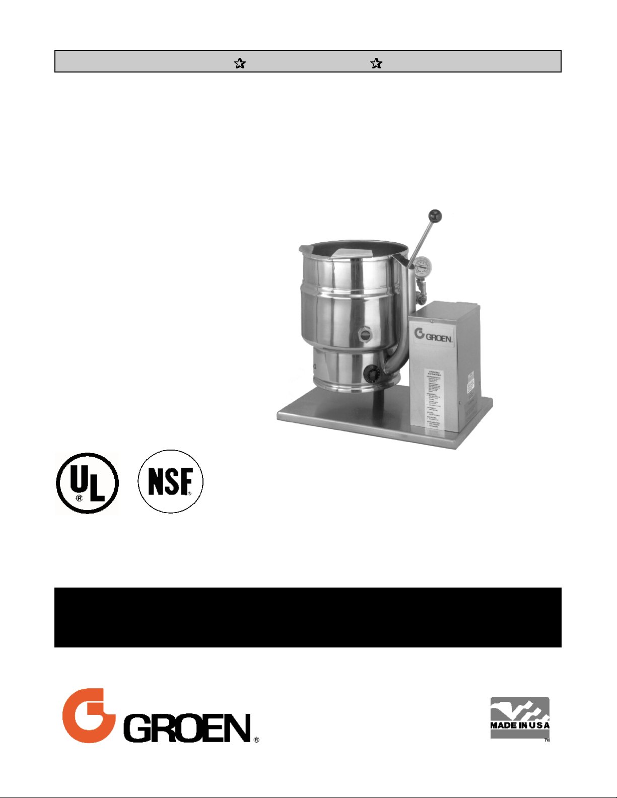
MODEL: TDB/7
Steam Jacketed Kettle
Self-Contained
Electrically heated
Table top mounted
Tilting
THIS MANUAL MUST BE RETAINED FOR FUTURE REFERENCE. READ,
UNDERSTAND AND FOLLOW THE INSTRUCTIONS AND WARNINGS
CONTAINED IN THIS MANUAL.
FOR YOUR SAFETY
DO NOT STORE OR USE GASOLINE OR OTHER FLAMMABLE VAPORS
AND LIQUIDS IN THE VICINITY OF THIS OR ANY OTHER APPLIANCE.
Information contained in this document is
known to be current and accurate at the time
of printing/creation. Unified Brands recommends referencing our product line websites,
unifiedbrands.net, for the most updated
product information and specifications.
Page 2

OM-TDB/7
IMPORTANT — READ FIRST — IMPORTANT
CAUTION: BE SURE ALL OPERATORS READ, UNDERSTAND AND FOLLOW THE OPERATING
INSTRUCTIONS,
WARNING: THIS UNIT IS INTENDED FOR USE IN THE COMMERCIAL HEATING, COOKING AND
HOLDING OF WATER AND FOOD PRODUCTS, PER THE INSTRUCTIONS CONTAINED IN
THIS MANUAL. ANY OTHER USE COULD RESULT IN SERIOUS PERSONAL INJURY OR
DAMAGE TO THE EQUIPMENT AND WILL VOID WARRANTY.
WARNING: KETTLE MUST BE INSTALLED BY PERSONNEL QUALIFIED TO WORK WITH ELECTRICITY.
IMPROPER INSTALLATION CAN RESULT IN INJURY TO PERSONNEL AND/OR DAMAGE TO
EQUIPMENT.
DANGER: ELECTRICALLY GROUND THE UNIT AT THE TERMINAL PROVIDED. FAILURE TO GROUND
UNIT COULD RESULT IN ELECTROCUTION AND DEATH.
WARNING: AVOID ALL DIRECT CONTACT WITH HOT EQUIPMENT SURFACES. DIRECT SKIN
CONTACT COULD RESULT IN SEVER E BURNS.
WARNING: AVOID ALL DIRECT CONTACT WITH HOT FOOD OR WATER IN THE KETTLE. DIRECT
CONTACT COULD RESULT IN SEVER E BURNS.
CAUTION: DO NOT OVER FILL THE KETTLE WHEN COOKING, HOLDING OR CLEANING. KEEP
LIQU IDS A MIN IMUM OF 2-3” (5-8 cm) BELOW THE KETTLE BODY RIM TO ALLOW
CLEARANCE FOR STIRRING, BOILING AND SAFE PRODUCT TRANSFER.
WARNING: TAKE SPECIAL CARE TO AVOI D CO NTACT WI TH HOT KETTLE BODY OR H OT PRODUCT
WHEN ADDING INGREDIENTS, STIRRING OR TRANSFERRING PRODUCT TO ANOTHER
CONTAINER.
WARNING: WHEN TILTING KETTLE FOR PRODUCT TRANSFER:
WEAR PROTECTIVE OVEN MITT AND PROTECTIVE A PRON.
1)
USE CONTAINER DEEP ENOUGH TO CONTAIN AND MINI MIZE PRODUCT SPLASH ING.
2)
3) PLACE CONTAINER ON STABLE, FLAT SURFACE, AS CLOSE TO KETTLE AS
POSSIBLE.
4) STAND TO LEFT OR RIGHT SIDE OF KETTLE (DEPENDING ON TILTING HANDLE
PLACEMENT) WHILE POURING . DO NOT STAND DIRECTLY IN POUR PATH OF HOT
CONTENTS.
POUR SLOWLY, MAINTAIN CONTROL OF KETTLE BODY HANDLE AT ALL TIMES, AND
5)
RETURN KETTLE BODY TO UPRIGHT POSITION AFTER CONTAINER IS FILLED OR
TRANSFER IS COMPLETE.
6) DO NOT OVER FILL CONTAINER. AVOID DIRECT SKIN CONTACT WITH HOT
CONTAINER AND ITS CONTENTS.
CAUTIONS, AND SAFETY INSTRUCTIONS CONTAINED IN THIS MANUAL.
CAUTION: KEEP
WARNING: FAILURE TO CHECK SAFETY VALVE OPERATION PERIODICALLY COULD RESULT IN
WARNING: WHEN TESTING, AVOID ANY EXPOSURE TO THE STEAM BLOWI NG OUT OF THE SAFETY
WARNING: TO AVOID INJURY, READ AND FOLLOW ALL PRECAUTIONS STATED ON THE LABEL OF
WARNING: BEFORE REPLACING ANY PARTS, DISCONNECT THE UNIT FROM THE ELECTRIC POWER
FLOORS IN FRONT OF KETTLE WORK AREA CLEAN AND DRY. IF SPILLS OCCUR,
CLEAN
PERSONAL INJURY AND/OR DAMAGE TO EQUIPMENT.
VALVE. DIR ECT CONTACT COULD RESULT IN SEVER E BURNS.
THE WATER TREATMENT COM POUND.
SUPPLY.
IMMEDIATELY, TO AVOID SLIPS OR FALLS.
2
Page 3

OM-TDB/7
IMPORTANT — READ FIRST — IMPORTANT
WARNING: KEEP WATER AND SOLUTIONS OUT OF CON TROLS AND ELECTRICAL EQUI PMEN T.
NEVER SPRAY OR HOSE THE SUPPORT HOUSING OR ELECTRICAL CONNECTION S.
CAUTION: MOST CLEANERS ARE HARMFUL TO THE SKIN, EYES, MUCOUS MEMBRANES AND
CLOTHING . PRECAUTIONS SHOULD BE TA KEN. WEA R RUBBER GLOVES, GOGGLES OR
FACE SHIELD AND PROTECTIVE CLOTHING. CAREFULLY READ THE WARNINGS AND
FOLLOW THE DI RECTIONS ON THE LA BEL OF THE CLEANER TO BE USED.
CAUTION: USE
OF ANY REPLACEMENT PARTS OTHER THAN THOSE SUPPLIED BY GROEN OR THEIR
AUTHORIZED
EQUIPMENT, AND WILL VOID ALL WARRANTIES.
DISTRIBUTORS CAN CAUSE OPERATOR INJURY AND DAMAGE TO THE
IMPORTANT:
SERVICE PERFORMED BY OTHER THAN FACTORY AUTHORIZED PERSONNEL WILL VOID
WARRANTIES.
3
Page 4

OM-TDB/7
Table of Contents
IMPORTANT OPERATOR WARNINGS ................................................................ 2
EQUIPMENT DESCRIPTION ......................................................................... 5
INSPECTION & UNPACKING ......................................................................... 7
INSTALLATION .................................................................................... 8
INITIAL START-UP ................................................................................. 9
OPERATION...................................................................................... 10
SEQUENCE OF OPERATION ....................................................................... 12
MAINTENANCE ................................................................................... 13
CLEANING ....................................................................................... 17
TROUBLESHOOTING .............................................................................. 19
PARTS LISTS
Units Manufactured Before Sept. 1, 1988 ........................................................... 20
Units Manufactured Between Sept. 1, 1988 and July 1, 1992 ........................................... 22
Units Manufactured Between July 1, 1992 and Feb. 6, 1995 ............................................ 24
Units Manufactured After Feb. 6, 1995 ............................................................. 26
DIAGRAMS & SCHEMATICS
Units Manufactured Before Sept. 1, 1988 ........................................................... 30
Units Manufactured After Sept. 1, 1988 and
Before June 1, 1990 ........................................................................ 33
Units Manufactured After June 1, 1990 and
Before July 1, 1992 ......................................................................... 36
Units Manufactured After June 1, 1990 and
Before Feb. 6, 1995 ......................................................................... 37
Units Manufactured After July 1, 1992 a nd
Before Feb. 6, 1995 ......................................................................... 38
Units Manufactured After Feb. 6, 1995 ............................................................. 39
SERVICE LOG .................................................................................... 42
REFERENCES .................................................................................... 42
WARRANTY ...................................................................................... 43
4
Page 5

Equi p men t D escr i p ti o n
OM-TDB/7
The Groen TDB/7 is a table t op, tilti ng, steam
jacket ed kettle with a ther m ostatica lly controlled,
self-contained, electrica lly -heat ed steam supply a nd
appropriate cont rols, m ounted on a st urdy ba se. The
Model TDB/7 is avai labl e in 20 or 40 - quar t capacity.
The body of th e TDB /7 Kett le is con structed of
stain less steel , welded in to one solid piece. Th e
kettle is furnished with a reinforced rim and a
butter fl y shaped pouri ng lip. It has a st eam jacket
rated for worki ng pressur es up to 50 PSI. Kettle
fin ish i s 180 em ery grit on the i nside an d bright semi deluxe on the outside. A tilt handle allows the
operator to manually tilt the kettle body in a
controlled manner. Pouring height accepts pans up to
4 inches high on a table top.
A built-in steam generator , siz ed for the ket tle
capacity and heated by electrici ty, delivers steam
into the jack et. “Airl ess” operation of the st eam
jacket permits uniform , efficient h e ating at
temperat ures as low as 150°F and as high as 295°F.
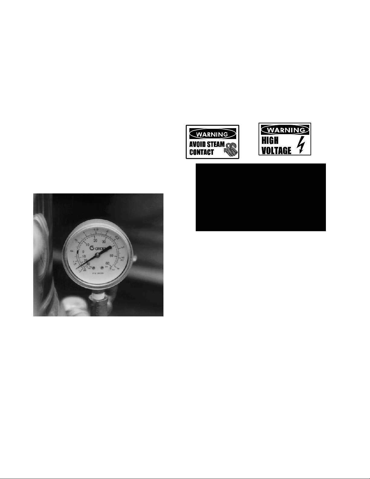
In addition to th e adjust able thermostat for operating
control, the unit has a tilt cut-off switch, low water
cut-off, safety valv e, and high-limit pressure swit ch
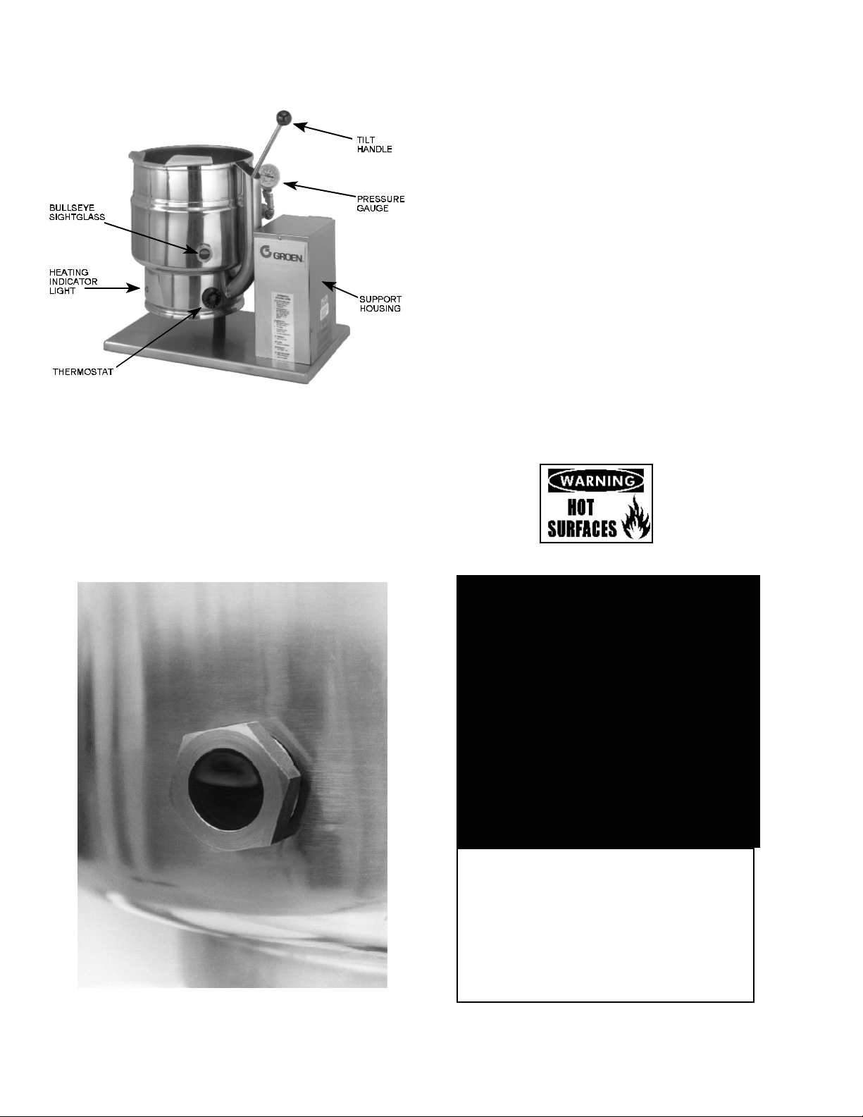
as safety features. A heating indicator light,
pressure gauge, and sight glass are pr ovided for
monitor ing kett le operation.
A single electrical connection is required for
insta lla tion. The uni t may be ordered for use wi th
208/240 or 480 volt power. All kettles are wired for
three- phase opera tion. For single-phase conver sion,
see the wiring diagrams in this manual.
KETTLE CHARACTERISTICS
TDB/7-20+ TDB/7-40
Kett le Capacity 20 qts. 18.8 l iter s 40 qts. 37.6 lit ers
Jacket Capacity 4 qts. 3.7 l iter s 5 qts. 4.7 liter s
Diameter 14” 36 cm 16-1/ 2” 42 cm
Depth 11” 28 cm 14-1/ 4” 36 cm
K.W. at 208 V 6.3 10.8
K.W. at 240 V 8.4 14.4
K.W. at 480 V 6.3 12.0
Base Width 24” 60 cm 24” 60 cm
Base Depth 16” 41 cm 16” 41 cm
5
Page 6
OM-TDB/7
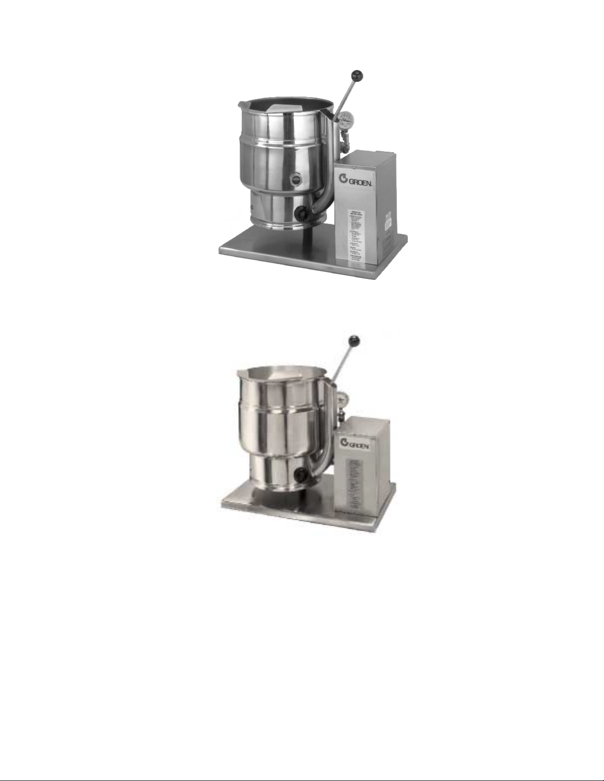
New/Current Models
Pre- Feb . 1995 Models
Opti onal equ ipment available wit h any model:
Stand that support s the unit a nd holds a pan in position for fillin g
1.
Lift-off cover
2.
Basket insert
3.
Fill faucet
4.
Manual stirrers
5.
Motor dr iven agita tor
6.
6
Page 7
Insp ecti o n & U n p acki n g
OM-TDB/7
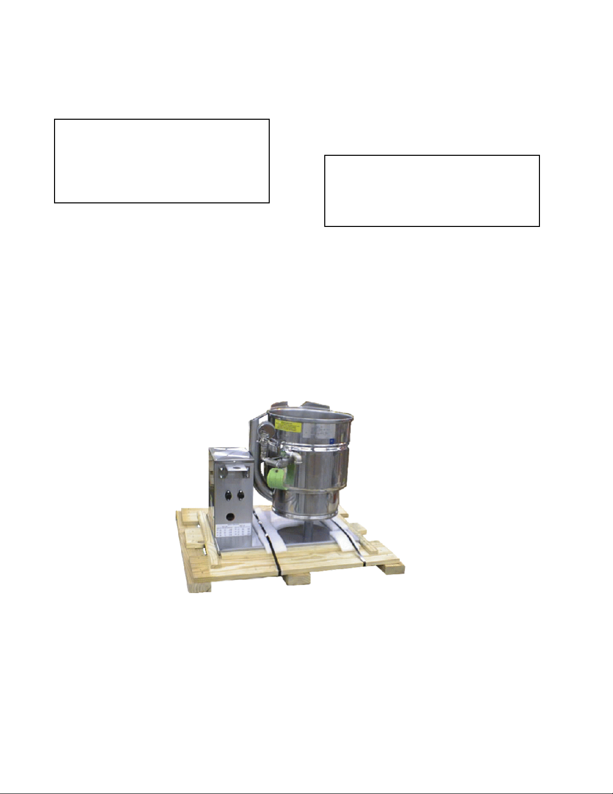
The unit will arrive in a heavy shipping carton and will
be atta ched to a skid. Imm ediately upon receipt,
inspect the cart on carefu lly for ext erior dam age.
CAUTION
SHIPPING STRAPS ARE UNDER TENSION
AND CAN SNAP BACK WHEN CUT. TAKE
CARE TO AVOID PERSONAL INJURY OR
DAMAGE TO THE UNIT BY STAPLES LEFT
IN THE WA LLS OF THE CARTON.
Careful ly cut the polyester straps ar ound the carton
and detach the sides of the box from the skid. Pull
the carton up off the unit.
Thoroughly inspect th e unit for concealed da m age.
Report any shipping dama ge or incorrect shipments
to t he delivery agent.
Writ e down the model number, ser ial number, and
installation date, and retain this information for future
reference. Space for these entr ies is pr ovided at the
top of the Service Log at the back of th is manual.
Keep this manual on file and available for operators
to use.
CAUTION
T HIS UNIT WEIGHS 140 TO 163 LB. (64 T O
74 KG). INSTALLER SHOULD OBTAIN
HELP AS NEEDED TO LIFT T HIS WEIGHT
SAFELY.
When instal lation is to begi n, car efull y cut the stra ps
which hold the unit on the skid. Lift the unit straight up
off the skid. Ex amine packi ng materia ls to be sure
loose parts are not discarded with th e m aterials.
Attach the tilt handle (normally shipped inside th e
kettle) by carefully threading it into the socket on the
trunnion support. Be careful to avoid cr oss-threadin g
fin e socket th reads.
The TDB/7 i s shipped from the factory strapped on a
pallet. The tilt handle is inside the kettle.
7
Page 8
OM-TDB/7
Installation
The Groen Kettle is provided w ith
complete internal wiring. It is ready for
immediate connection. A wiring diagram
is pr ovided i n this manual and on the
inside of the control housing serv ice
panel. Any mechanical or electrical changes must be
approved i n by Groen’s Food Service Engineering
Department.
WARNING
INSTALLATION OF THE KETTLE MUST BE
DONE BY PERSONNEL QUALIFIED TO
WORK WITH ELECTRICITY. IMPROPER
INSTALLATION CAN RESULT IN INJURY
TO PERSONNEL AND/OR DAMAGE TO
EQUIPMENT.
The completed uni t has been operated at the factory
to test all controls and heater elements.
1. Set the kett le in place and level it. The base
should be securely fasten ed to a tabl e or work
surface. Four 3/8”-16 N.C. threaded cou plings
are prov ided in th e base of u nit. Insta llation
under a venti lat ion hood is recommen ded.
2. Prov ide elect rical pow er as specified on th e
elect rical inform ation plate at tached to the
equipment. Observe l ocal codes an d/or The
National Electrical Code in accordance wit h
ANSI/NFPA 70 - (current edition).
The equipment is shipped rea dy for three phase
3.
operation. Refer to the wiring diagra m for sin gle
phase operation.
Bri nging t he electri cal service throu gh the
4.
entra nce at t he rear of the support housin g,
making a watertight connection with the
incoming lines. (A BX connection is not
recommended.)
DANGER
ELECTRICALLY GROUND THE UNIT AT
THE TERMINAL PROVIDED. FAILURE TO
GROUND UNIT COULD RESULT IN
ELECTROCUTION AND DEATH.
Confirm that the jacket water level is above
5.
mid point of si ght gla ss (new models) or
between the marks on the gauge gla ss (old
models). If the lev el is low, follow the
instructions under “Jacket Filling and Water
Treatment” in the “Maintenance” section of
the manual.
The open end of t he elbow on th e outlet of
6.
the safet y valve must be directed downward
on old models. If it is not, turn t he elbow t o
the corr ect posit ion. On new models the
safet y val ve points down.
Any mechanical or electrical change must be
7.
approved by th e G roen Food Servi ce
Engineer ing Departmen t.
TDB/7 ELECTRICAL SPECI FICATION S
20 QUARTS 40 QUARTS
VOLTAGE PHASE KW AMPS KW AMPS
208 1 6.3 31 10.8 52
208 3 6.3 18 10.8 30
240 1 8.4 35 14.4 60
240 3 8.4 20 14.4 35
480 1 6.3 13 12.0 25
480 3 6.3 8 12.0 15
400 3 7.8 11.2 13.2 19
TDB/7 SUPPLY WIR E REQUIREMENTS
Copper only, THHN ( 90°C)
20 QUARTS 40 QUARTS
VOLTAGE PHASE AWG mm AWG mm
208 1
3
240 1
3
480 1
3
400 3 — 1.8 —
8
12——
8
3.0
10
—
1414——10
8
12
6
—
8
—
4
3.5
8
—
2.5
Page 9
OM-TDB/7
Initial Start-Up
IMPORTANT:
BE SURE ALL OPERATORS READ, UNDERST AND AND FOLLOW T HE OPERATING
INSTRUCTIONS, CAUTIONS, AND SAFETY INSTRUCTIONS CONTAINED IN THIS MANUAL.
Now that the kett le has been inst alled, you should
test it t o ensure t hat t he uni t is oper ating correctly.
1. Remove all literatur e and packin g m aterials
from i nside an d outside of the unit.
2. Tu rn on the electrical servi ce to th e unit .
3. Pour 1-2 quarts of water into the kettle.
4. Following “To Start Kettle” instructions in the
“Operation” section of this manual, begin
heating the water at th e highest thermostat
setting. The heating indicator light should
come on immediately, and heat ing should
continue until the water boils.
5. To shut down the unit, turn the thermostat
dial to “OFF”.
WARNING
AVOID ALL DIRECT CONTACT WITH HOT
SURFACES. DIRECT SKIN CONTACT
COULD RESULT IN SEVER E BURNS.
AVOID ALL DIRECT CONTACT WITH HOT
FOOD OR WATER IN THE KETTLE.
DIRECT CONTACT COULD RESULT IN
SEVERE BURNS.
If the unit functions as described above, it is r eady
for u se. If the unit does not function as i ntended,
contact your l ocal Groen C erti fi ed S ervi ce A gency.
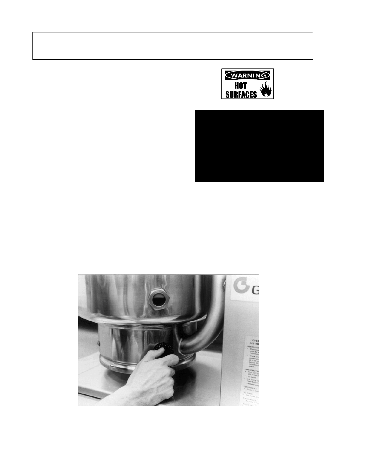
A simple turn of the thermostat controls the Groen TBD/7 Kettle
9
Page 10
OM-TDB/7
The operat or controls ket tle heat ing with the
thermost at dia l. Th e dial tu rns heating element
elect ric power on or off and sets t he operat ing
temperat ure of the kettle.
Operation
2. Check t he pressure gauge. If the gauge
3. Tu rn on the electrical pow er to the unit.
4. Tu rn the t hermostat dial to the desir ed
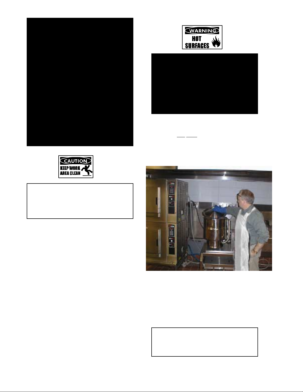
To Transfer Product or Empt y Kettl e:
B.
The kettle is designed and manufactured to be
tilted in a controlled manner. Grasp the insulated
plastic ball firmly. Maintain a firm grip on handle
when tilting, while keeping k ettle body in a tilted
posit ion and when SLOWLY returning the kettle
body to an uprigh t posit ion.
(ol d m odels). If t he level is too low, see
“Jacket Filling and Water Treatment” on
page 10 of this manual.
does not show 20 to 30 inches of v acuum
(t hat is, a readi ng of 20 to 30 below 0), see
“Jacket Vacuum” on page 10 of this manual.
setting. The heating indicator light indicates
that the kettle is heating, and cycling of the
light on and off indicates that the kettle is
being held at the set temperature. Once in
each cycle the conta ctors i n the support
housing will make a clicking sound. This is
normal.
A. To Start Kettle
EVERY DAY make sure tha t th e j acket
1.
water level is above th e m id-poi nt of the
round sight glass (new models) or
between the marks on the gauge glass
On most TDB/7 units the jacket water level is
shown in a sight glass, right on t he kettle.
WARNING
AVOID ALL DIRECT CONTACT WITH HOT
SURFACES. DIRECT SKIN CONTACT
COULD RESULT IN SEVER E BURNS.
AVOID ALL DIRECT CONTACT WITH HOT
FOOD OR WATER IN THE KETTLE.
DIRECT CONTACT COULD RESULT IN
SEVERE BURNS.
TAKE SPECIAL CARE T O AVOID CONT ACT
WITH HOT KETTLE BODY OR HOT
PRODUCT, WHEN ADDING INGREDIENTS,
STIRRING OR TRANSFERRING PRODUCT
TO ANOTHER CONTAINER.
CAUTION
DO NOT OVERFILL THE KETTLE WHEN
COOKING, HOLDING OR CLEANING.
KEEP LIQUIDS AT LEAST 2-3” (5-8 cm)
BELOW THE KETTLE BODY RIM TO
ALLOW CLEARANCE FOR ST IRRING,
BOILING PRODUCT AND SAFE
TRANSFER.
10
Page 11
WARNING
WHEN TILTING KETTLE FOR PRODUCT
TRANSFER:
1) WEAR PROTECTIVE OVEN MITT AND
PROTECTIVE APRON.
USE DEEP CONTAINER TO CONTAIN
2)
AND MINIMIZE PRODUCT SPLASHING.
PLACE CONTAINER ON STABLE, FLAT
3)
SURFACE, AS CLOSE TO KETTLE AS
POSSIBLE.
STAND TO LEFT OR RIGHT OF KETTLE
4)
(DEPENDING ON HANDLE PLACEMENT)
WHILE POURING — NOT DIRECTLY IN
POUR PATH OF HOT CONTENTS.
5) POUR SLOWLY, MAINTAIN CONTROL OF
KETTLE BODY HANDLE AT ALL TIMES,
AND RETURN KETTLE BODY TO
UPRIGHT POSITION AFTER CONTAINER
IS FILLED OR TRANSFER IS COMPLETE.
DO NOT OVERFILL CONTAINER. AVOID
6)
DIRECT SKIN CONTACT WITH HOT
CONTAINER AND ITS CONTENTS.
OM-TDB/7
WARNING
AVOID ALL DIRECT CONTACT WITH HOT
SURFACES. DIRECT SKIN CONTACT
COULD RESULT IN SEVER E BURNS.
AVOID ALL DIRECT CONTACT WITH HOT
FOOD OR WATER IN THE KETTLE.
DIRECT CONTACT COULD RESULT IN
SEVERE BURNS.
When removing cover:
a) Firmly grasp plastic handle
b) Lift rear
(3-5 cm) to allow any steam and water vapor
to escape the cooki ng vessel. Wa it 2- 3
seconds.
c) Tilt cover to 45-60° angle and allow any hot
edge (fa rthest from operator) 1-2”
CAUTION
KEEP FLOORS IN FRONT OF THE KETTLE
WORK AREA CLEAN AND DRY. IF SPILLS
OCCUR, CLEAN AT ONCE TO AVOID
SLIPS OR FALLS.
Common Accessories
Lift Off Cov e r
1.
As with stock pot cooking, an optional lift off
cover can speed up the heatin g of water and
food produ cts. A cover helps r etain heat in
the cooki ng vessel a nd reduces t he amount
of heat and humidity released into the
kitchen. Use of a cover can reduce some
product cook times and help maintain the
temperat ure, color and texture of products
being hel d or simmered for extended peri ods.
Make sure the plastic ball handle is secure on
the lift off cover before using. ALWAYS use
the plastic handle to place or remove cover
from t he kettle. Wear prot ectiv e oven mit ts
and a protective apron.
Lif t the rear edge of the cover first.
condensate or product to roll off cov e r back
into kettle.
d) Remove cover, ensuring that any remaining
hot condensate or pr oduct does not drip on
operator , floor or work surfa ces.
e) Place cover on safe, flat, sanitary, out-of-
the-way surface, or return to kettle rim.
When putting the cover on the k ettl e, posit ion
it on top of kettle rim, with its flat edge facing
the pour ing lip.
CAUTION
DO NOT TILT KETTLE BODY WI TH COVER
IN PLACE. CO VER MAY SLI DE O FF,
CAUSING INJURY TO OPERATOR.
11
Page 12
OM-TDB/7
2. Ba sket Insert
An optional kettle basket insert ca n assist in
cooking water- boiled pr oducts including
eggs, pot atoes, vegetables, shell fish, pa sta
and rice. The nylon mesh liner must be used
when cooking product smaller than the mesh
size of the basket, which is a pproximately
1/4” (6 mm). This includes rice and small
pasta shapes.
Tips For Use.
a) Allow for the water displacement of the
basket and product to be cooked. Thi s
may mean only filling the kettle half full of
water. Test the basket a nd product
displacement with the kettle OFF, and
with cold water in the kettle.
CAUTION
DO NOT OVERFILL THE KETTLE WHEN
COOKING, HOLDING OR CLEANING. KEEP
LIQUIDS A MINIMUM OF 2-3” (5-8 cm)
BELOW THE KETTLE BODY RIM TO
ALLOW CLEARANCE FOR STIRRING,
BOILING AND SAFE PRODUCT TRANSFER.
AVOID ALL DIRECT CONTACT WITH HOT
FOOD OR WATER IN THE KETTLE.
DIRECT CONTACT COULD RESULT IN
SEVERE BURNS.
Load basket on a level, stable work surface.
b)
Lift the l oaded basket wi th both hands. Get
c)
help from a nother person if the basket is too
heavy for safe handling.
Slowly low er product into ket tle.
d)
When removing basket w ith cooked pr oduct,
e)
lift basket straight up, ensuring bottom of
basket cl ears the rim and pour ing lip of the
kettle. Wear protective oven mitts and
prot ective apr on.
Allow hot water to fully drain from product,
d)
before movin g basket a way fr om the kett le.
Do not rest kettle basket on kettle rim or
pourin g lip. If basket is too h eavy for
individual to lift and safely move, get help
from another person. Remov e product
immediately fr om basket into anoth er
container, being sure to avoid contact with
hot product a nd hot basket or. . .
e) Place basket with food on stable, flat
surface, setti ng it inside a solid steam er or
bake pan, to catch any remaining hot water
drain ing fr om product.
WARNING
AVOID ALL DIRECT CONTACT WITH HOT
SURFACES. DIRECT SKIN CONTACT
COULD RESULT IN SEVER E BURNS.
Sequen ce o f Op er ati o n
The fol lowing “a ction-reaction” outline is provided
to help the user understand how the equipment
works.
When the operat or start s up the k ettle by tur ning
the opera ting th ermostat dial from “OFF” to a
desir ed setti ng, th e thermostat switch closes.
This lights up the heating indicator light and
causes the contactors to close, allow ing power
to flow to heating elements. When the
temperatur e of the st eam jacket r eaches the
value corresponding to the dial setting, the
thermostat switch opens. Thi s turns off the
heating indicator light and causes the contactors
to open, stopping the power to the heaters. As
soon as the thermostat senses that the kettle is
cooling below t he set point, the thermostat
switch closes, the heati ng indicator light comes
on, th e contact ors close, and the heater s com e
on again . On-off cyclin g contin ues, keeping the
kettle at the set temperature This is why th e
heating indicat or light cycl es on and off du ring
normal operation. Every time the kettle is tilted,
the tilt cut- off switch int errupts t he power supply
to t he heat ers, so that the heati ng element s will
not operate w hile no t submerged in th e jacket
water.
If steam pressure greater than 50 PSI is
generated in the jacket, the safety valve will open
and relieve the excess pressur e.
In the event that the jacket water level gets too
low and the heating element s overhea t, t he high limit control will open and shut off power to t he
elements until the kettle cools. Setting the
operating ther m ostat dia l to “OFF” sh uts down al l
control and heating circuits.
12
Page 13
Maintenance
NOTICE: Contact Groen or an authorized Groen representative when repairs are required.
Periodic Maintenance
1.
A Maintenance & Service Log is provided a t
the back of this manual with the warranty
information. Each time maintenance is
perform ed on your G roen kett le, enter the
date on which t he work was done, w hat was
done, and who did it. Keep this manual on
file and avai labl e for operators to use.
Periodic inspection will minimize equipment
down time a nd incr ease the effici ency of
operation. The following poi nts shou ld be
checked:
[BY OPERATOR]
a. Check t he pressur e/vacuum gauge every
day. The gauge should show a vacuum
of 20 to 30 inches, when the ket tle is
cold. If it does not, see “Jacket Vacuum”
on page 10.
month. Test the valve with the kettle
operating at 15 psi (105 kPa) , by holdi ng the
test lever for a t least 5 seconds. Then
release the lever and let the valve snap shut.
If the lever does not activate, or ther e is no
evidence of discharge, or the v alve leaks,
immediately discont inue use of the kettle and
contact a qualified Groen service
representative.
WARNING
WHEN TESTING, AVOID ANY EXPOSURE
TO THE STEAM BLOWING OUT OF THE
SAFETY VALVE. DIRECT CONTACT
COULD RESULT IN SEVER E BURNS.
DISCONNECT ELECTRICAL POWER FROM
THE KETTLE BEFORE ATTEMPTING TO
GREASE THE TRUNNION BEARINGS.
OM-TDB/7
The pressure gauge should show a vacuum
of 20 t o 30 inches when the kettl e is cold.
b. Also check the ja cket water level on a
daily basis. It shoul d be above mid poi nt
of rou nd sight glass (new models) or
between the marks on the gauge glass
(ol d m odels). If t he level is low, see
“Jacket Filling and Water Treatment” on
page 14.
[BY SERVICE TECHN ICIA N]
c. Electrica l wiri ng should be kept securely
connected an d in good condit ion.
d. Th e insi de of the support housin g should
be kept clea n.
Test the safety valve at least twice each
13
At least twice a year, grease the two
trunnion bearings. The bearings are located
within the kett le support h ousing. R em ove
the access panels from the support housing
with a screwdriver to gain access to the
grease fittings. Use a lithium-based, multipurpose grease. When the access panels
are removed, the mounting bolts for the
trunnion bearings and tilt switch can also be
checked for t ightness. When finished,
reassemble access panel s to support
housing.
Jacket Vacuum
2.
When the kett le is cold, a positive pressur e
reading or a reading around zero on the
pressure/ vacuum gauge indicates th e
presence of air in the jack et. Ai r in the jack et
slows down the h eating of the kett le.
To remove air:
a. Start the unit. (See the “Operation”
section of this manual.) (Be sure there is
water or product in the kett le when
heating).
b. When the pressu re/va cuum gauge
reaches a posit ive pressur e readin g of 5
PSI, r elease t he tra pped air and steam
by pulling up or out on the safety valve
Page 14
OM-TDB/7
lever or ring for about 1 second. R epeat
this step, then let the pull ring or valve
lever sn ap back int o the closed position.
Jacket Filling and Water Treatment (For
3A.
units manufactured before July 1, 1992) *
The jacket was charged at the factory with
the proper amount of treated water. You
may need to r estore t he water t o its pr oper
level, either because water was l o st as
steam during venting or because treated
water was lost by draining.
If you are replacing w ater lost as steam,
a.
use distilled wat er. If you are r eplaci ng
tr eated water that r an out of the j acket,
prepare more treated water as directed
in step 4, “Wa ter Tr eatment Procedure.”
All ow the k ettl e to cool. Turn the elbow
b.
on the safety valv e counter clockwise ( to
avoid t hread da m age) until th e opening
of th e elbow faces upward.
c. Open t he safety valv e and pour th e
water or trea ted wat er in at the elbow
until the water level rises to a point
between the marks on the gauge gla ss.
CAUTION
BEFORE YOU HEAT THE KETTLE FOR
ANY PURPOSE, TURN THE ELBOW
CLOCKWISE UNTIL THE OPENING AGAIN
FACES DOWNW ARD.
e. Air intr oduced to the jacket during the
filling operation m ust be remov ed to
obtain efficient heati ng. See “Jacket
Vacuum” above.
* Date of manufacture stamped on National
Board dat a plate.
Jacket Filling and Water Treatment (For
3B
units manufactured July 1, 1992 to Feb.
6, 1995) *
The jacket was charged at the factory with
the proper amount of treated water. You
may need to r estore t he water t o its pr oper
level, either because water was l o st as
steam during venting or because treated
water was lost by draining.
IMPORTANT: The pr essure gau ge m ust rea d 0
PSI or less before you fill jacket
with wa ter.
To fill jacket with water:
If you are replacing w ater lost as steam,
a.
use distilled wat er. If you are r eplaci ng
tr eated water that r an out of the j acket,
prepare more treated water as directed
in step 4, “Wa ter Tr eatment Procedure.”
b. Tilt k ettl e 90° to a fu ll pour position.
c. Remove fill plug with open-end wrench or
crescent wrench.
d. Open shutoff valve (turn handle 90° on
ball valve).
Use a funnel and add water to jacket.
e.
Check water level in jacket by tilting
f.
kettle to operating position and viewi ng
water ga uge glass.
g. Repeat steps e and f until water level is
between t he maxi mum and mini mum
indica tion marks on the water gauge
glass.
h. Close shutoff valve, install fill plug, and
ret urn k ettl e to operating position.
Follow procedure under “Ja cket Vacuum” to
remove air from kettle jacket.
* Date of manufacture stamped on National
Board dat a plate.
C Jacket Filling and Water Treatment (For
units manufactured after Feb. 6 1995) *
The jacket was charged at the factory with
the proper amount of treated water. You
may need to r estore t he water t o its pr oper
level, either because water was l o st as
steam during venting or because treated
water was lost by draining.
IMPORTANT
Pressure gauge must read 0 PSI or less
before you fill jacket wi th water.
To fill jacket with water:
a. If you are replacing water lost as steam,
use distilled wat er. If you are r eplaci ng
tr eated water that r an out of the j acket,
prepare more treated water as directed
in step 4, “Wa ter Tr eatment Procedure”.
b. Remove fill plug with open -end wrench or
crescent wrench.
c. Open shutoff valve (turn handle 90° on
ball valve).
d. Use a funnel and add water to jacket.
e. Check water level in jacket, by viewing
water level indicator glass.
Continue to add water until the water
f.
level indicator glass is 3/4 full.
Close shutoff valve, an d install fill plug.
g.
Follo w procedur e in “Jacket Vacuum” to
remove air from kettle jacket.
* Date of manufacture stamped on National
Board dat a plate.
14
Page 15

OM-TDB/7
15
Page 16

OM-TDB/7
4. Water Treatment Procedure
WARNING
TO AVOID INJURY, READ AND FOLLOW
ALL PRECAUTIONS STATED ON THE
LABEL OF THE WATER TREATMENT
COMPOUND.
(1) Fill the mixing container with the
measured amount of water required.
(See t he tabl e at right) . Dist ill ed water is
recommended.
(2) Hang a str ip of pH test pa per on the rim
of the container, with about 1 inch of the
str ip below the sur face of th e water .
(3) Measure the water treatment compound
you will be using. (One way to do this is
to add the compound from a measuring
cup.)
(4) Stir the water continuously, while you
slowly add water t reatment compound,
until t he water r eaches a pH between
10.5 and 11. 5. Judge the pH by
frequ ently com parin g the col or of the test
str ip with th e color chart provided in the
pH test kit. Color blind people mi xing the
treated water solution must use an
electroanalytical instrument to measure
the pH level or have a person that is not
color blind read the test strip color level.
(5) Record the ex act amount s of water and
tr eatment com pound used. These
amounts may be used again, if the same
sources of water and compound are
employed to refill the jacket in the future.
However, it i s advisa ble to check t he pH
every t ime treat ed water is prepa red.
Model Kettle
Capacity
TDB/7-20 20 quart s 4 quart s
TDB/7-40 40 quart s 5 quart s
Component Replacement
5.
WARNING
BEFORE REPLACING ANY PARTS,
DISCONNECT THE UNIT FROM THE
ELECTRIC POWER SUPPLY.
All internal wiring is marked as shown on the
circuit schematic drawings. Be sure that new
components are wired in the same manner
as the ol d com ponents.
Jacket
Capacity
16
Page 17

Suggested Tools:
1.
a. Cleaner, such as Klenzade HC-10 or HC-
32 from ECOL AB, Inc.
b. Kettle brushes in good con dition.
c. Sanitizer such as Klenzade XY-12.
d. Film remover such as Kl enzade LC-30.
Precautions
2.
Before cleaning, shut off the kettle by turning
the thermostat dial to “OFF,” and shut off all
electric power to the unit at a remote switch,
such as th e circuit breaker .
WARNING
KEEP WATER AND SOLUTIONS AWAY
FROM CONTROLS AND ELECTRICAL
EQUIPMENT. NEVER SPRAY THE
SUPPORT HOUSING OR ELECTRICAL
CONNECTIONS.
OM-TDB/7
Cleaning
c. Prepare a hot solution of the det ergent/
cleaning compound as instructed by the
supplier. Clean the uni t thoroughl y. A
cloth moistened with cleaning solution
can be used to clean controls, housings,
and electrical conduits.
d. Rinse the k ettl e thoroughly with hot
water, then drain completely.
e. As pa rt of the daily clean ing progra m ,
clean soiled external and internal
surfaces. Remember t o check the sides
of the unit and control housing.
f. To remove stuck materials, use a brush,
sponge, cloth, pla stic or rubber scraper,
or plastic wool with the cleaning solution.
To reduce effort r equired in washing, let
the detergent solu tion sit i n the k ettl e and
soak into the residue. Do NOT use
abrasive materials or metal tools that
might scratch the surface. Scratches
CAUTION
MOST CLEANERS ARE HARM FUL TO T HE
SKIN, EYES, MUCOUS MEMBRANES, AND
CLOTHING. PRECAUTIONS SHOULD BE
TAKEN. WEAR RUBBER GLOVES,
GOGGLES OR FACE SHIELD, AND
PROTECTIVE CLOTHING. READ THE
WARNINGS AND FOLLOW THE
DIRECTIONS ON THE LABEL OF THE
CLEANER CAREFULLY
Procedure
3.
a. Clean food-con tact surfaces a s soon as
possibl e after use. If t he uni t is in
continuous use, thoroughly clean and
sanitize the interior and exterior at least
once every 12 hours.
WARNING
AVOID ANY DIRECT CONTACT WITH HOT
SURFACES. DIRECT SKIN CONTACT COULD
RESULT IN SEVERE BURNS.
b. Scrape and fl ush out food residu es. Be
careful not to scratch the kettle with
metal i m plements.
Use only a sponge, cloth or plastic brush to
clean t he kettl e.
Scrapers or steel wool can harm the ket tle
surface.
17
Page 18

OM-TDB/7
make the surface harder to clean and
provide places for bacteria to gr ow.
i. It i s recommended th at each piece of
equipment be sanit ized j ust before use.
Do NO T use steel w ool, whi ch may leave
particles in the surface and cause
eventual corrosion and pitting.
g. Th e outside of th e unit m ay be polished
with a stai nless steel cleaner such as
“Zepper” from Zep Manufacturing Co.
h.h. When equi pm ent needs t o be sanitized,
use a solution equiv alent to one that
supplies 200 pa rts per million available
chlorine. Obtain advice on sanitizing
agents from your supplier of sa nitizing
products. Followin g the supplier’ s
instructions, apply the agent after the
unit has been cl eaned and drain ed. Rinse
off the sanitizer th oroughly.
NOTICE
NEVER LEAVE A CHLORINE SANITIZER IN
CONTACT WITH STAINLESS STEEL
SURFACES LONGER THAN 30 MINUTES.
LONGER CONT ACT CAN CAUSE STAINING
AND CORROSION.
j. If th ere is difficulty removin g m ineral
deposit s or a fi lm left by hard water or
food residues, clean the k e ttle thoroughly
and then use a del iming agent, li ke
Groen Delimer/Descaler ( P art N umber
114800) or Lime-Away from E colab, in
accordance with the manufacturer’s
directions. Rinse and drain the unit
before further u se.
k. If cleanin g problems persist, conta ct
your cl eaning produ ct represent ative for
assistance. The supplier has a trained
technical staff with laboratory facilities to
serve you.
18
Page 19

OM-TDB/7
Troubleshooting
Your Groen kettle is design ed to operate smoot hly a nd effici ently if properly maintained. However, t he
following is a list of ch ecks to make in the event of a pr oblem. Wirin g diagrams are furnished in side the
service panel. If an item on the list is followed by X, the work should be done by a qualifi ed servi ce
representative.
USE OF ANY REPLACEMENT PARTS OTHER THAN THOSE SUPPLIED BY GROEN OR THEIR
AUTHORIZED DISTRIBUTORS CAN CAUSE INJURY TO THE OPERATOR AND DAMAGE TO THE
EQUIPMENT AND WILL VOID ALL WARRANTIES.
SYMPTOM WHO WHAT TO CHECK
Xin dicates items which must b e performed by an authorized t echnician.
Kettle will not heat, and heating
indicator will not come on.
Kettle will not heat, but heating
indica tor comes on.
Kettle continues heating after it reaches
the desired temperature
Kett le stops heatin g before it reaches
the desired temperature.
Kettle heats slowly User a. For air in the jacket. See “Jacket Vacuum” in
Safety v alve pops. User a.
User a.
Aut h Service
Rep On ly
Aut h Service
Rep On ly
User a.
Aut h Service
Rep On ly
User a.
Aut h Service
Rep On ly
Aut h Service
Rep On ly
Aut h Service
Rep On ly
Elect ric power supply to the unit .
Water level in jacket.
b.
Control circuit fuses. Replace a blown fuse
c.
only with a fuse of the same AMP rating. X
d. For l oose or broken wir es. X
Til t cut-off sw itch. X
e.
That pressure switch is open. X
f.
g. Operati on of v ariable thermostat . X
Low wa ter cutoff. X
h.
a. Contactor. X
Heater elements with ohmmeter for ground
b.
short or open element . If element is defective,
call Groen. X
Thermostat dial setting.
Thermostat circuit for short . X
b.
Thermostat oper ation. The thermostat shoul d
c.
click when the dia l is r otated above and below
the setting for the temperature of the kettle. X
Contactor, to determine whether it is
d.
energiz ed or stuck. X
Thermostat dial setting.
Thermostat calibration. X
b.
Thermostat oper ation. The thermostat shoul d
c.
click when the dia l is r otated above and below
the setting for the temperature of the kettle. X
the “Maintenance” section of this manual.
b. Heater elements with ohmmeter for ground
short or open element . If an element is
defective, call Groen. X
Volt age of main power sour ce. X
c.
For air in th e jacket. See “Jacket Vacuum” in
the “Maintenance” section of this manual.
Pressure swi tch setti ng. X
b.
Thermostat oper ation. Thermostat shoul d
c.
click when the dia l is r otated above and below
the setting for the temperature of the kettle. X
Safety v alve. If the val ve pops at pr essures
d.
below 49 PSI, replace it. X
Contact or, to determine whether it is de-
e.
energiz ed. X
19
Page 20

OM-TDB/7
l. Par ts L i st
(For units manufactured before Septemb er 1, 1988) *
To order parts, contact your Groen Certified Service Agency. Supply the model designation, part
description, part number, quantity, and, where applicable, voltage and phase.
Key Description Part No. Key Description Part No.
1 Kettle Assembly TDB/7-20 003144 24 Street EL 1/4” IPS X 90” 010668
Kettle Assembly TDB/7-40 003145 25 Block, Pillow, 1-½” 002989
2 Base Assembly 054174 26 Collar, Set 003118
3 Bottom Cover 003141 27 Set Screw 3/8” - 16NC x ½” 003117
4 Gasket, U-channel 007937 28 Micro Switch 002982
5 Pedestal Weldment 002990 29 Bracket, Micro Switch 002988
6 Pedestal Cladding, 480V Only 003148 30 Contactor
Pedestal Cladding, 208-240V 003147 31 Transformer 012827
7 Screw #8 X ½” 005002 32 Fuse, 3 AMP, 480V Only 002651
8 Cap, Pedestal 003137 33 Terminal Block, 208-240V 002864
9 Cover, TDB/7-40 003136 Terminal Block, 480V 003119
Cover, TDB/7-20 003139 34 Fuse Holder 002944
10 Screw, RHMS #8-32 X 3/8” 005724 35 Fuse
11 Nut, KEPS 1/4” X 20 NC 012940 36 Screw, RHMS #8-32 X 3/4” 012656
12 Handle Assembly 012695 37 Spacer 003146
Ring, Tolerance 012692 38 Screw Hex Head ½”-13 NCx3½” 003285
13 Bumper, TDB/7-40 003248 39 Nut, Hex ½” - 13 NC 005705
Bumper, TDB/7-20 003241 40 Lock Washer ½” 005735
14 Washer (As Required) 003242 41 Pressure Gauge 001594
Washer (As Required) 003243 42 Fittings, Gauge Glass 002845
15 Screw, Hex Head ½” - 13 NC X 1” 005622 43 Rubber Gauge Glass Gasket 008917
16 Thermostat 012313 44 Washer (With Item 42)
17 Screw, RHMS #6-32 NC X ½” 012603 45 Hex Nut (With Item 42) Õ
18 Knob, Thermostat 002868 46 Glass, Gauge 002987
19 Pilot Light, 208-240V 016028 47 Rod, Gauge Glass Guard 003127
Pilot Light, 480V 002986 48 Nut, Dome #10 - 24 NC 005470
20 Basket for TDB/7-20 001607 49 Thermostat, High Limit 004588
Basket for TDB/7-40 001121 Bracket, Bottom 002916
21 Cover, One Piece Lift-off, TDB/7-40 013496 Grommet, Thermostat 001518
Cover, One Piece Lift-off, TDB/7-20 001566 Grommet, Trunnion 003492
22 Knob, Maroon Ball 012691 Grommet 007400
23 Valve, Safety 005587 Elbow 004185
(See table)
(See table)
Õ
ELECTRICAL PARTS TABLE
Model KW AMP Contactor Pilot Light Transformer Wire H arness Fuse
TDB/7-20
208V/1 Ph 6.3 31 009173 016028 N one 003175 002945
240V/1 Ph 6.3 27 009178 016028 N one 003175 002945
480V/1 Ph 6.3 14 009576 002986 012827 003172 002651
208V/3 Ph 6.3 18 009210 016028 N one 003174 002945
240V/3 Ph 6.3 16 009210 016028 N one 003174 002945
480V/3 Ph 6.3 8 009574 002986 012827 003170 002651
TDB/7-40
208V/1 Ph 10.8 52 013368 016028 None 003168 002945
240V/1 Ph 12 50 013368 016028 Non e 003168 002945
480V/1 Ph 12 25 009576 002986 012827 003166 002651
208V/3 Ph 10.8 30 009210 016028 None 003167 002945
240V/3 Ph 12 30 009210 016028 Non e 003167 002945
480V/3 Ph 12 15 009574 002986 012827 003165 002651
* Date of manufacture is stamped on National Board dat a plat e.
20
Page 21

OM-TDB/7
(For units manufactured before September 1, 1998)
21
Page 22

OM-TDB/7
Parts Li st
(For units manufactu red betw een Sept ember 1, 1988 and Jul y 1, 1992)*
To order parts, contact your Groen Certified Service Agency. Supply the model designation, part
description, part number, quantity, and, where applicable, voltage and phase.
Key Description Part No. Key Description Part No.
1 Kettle Assembly TDB/7-20 003144 24 Street el 1/4” IPS X 90” 010668
Kettle Assembly TDB/7-40 003145 25 Block, Pillow, 1-½” 002989
2 Base Assembly 054174 26 Collar, Set 003118
3 Bottom Cover 003141 27 Set Screw 3/8” - 16 NC X ½” 003117
4 Gasket, U-channel 007937 28 Micro Switch 002982
5 Pedestal Weldment 002990 29 Bracket, Micro Switch 002988
6 Pedestal Cladding, TDB/7-40 003149 30 Contactor
Pedestal Cladding, TDB/7-20 003147 31 Transformer 086876
7 Screw #8 X ½” 005002 32 Fuse, 480v Only 055572
8 Cap, Pedestal 003137 33 Terminal Block 088214
9 Cover, TDB/7-40 003136 34 Fuse Holder 208/240V Only 002944
Cover, TDB/7-20 003139 35 Fuse 208/240V Only
10 Screw, RHMS #8-32 X 3/8” 005724 36 Screw, RHMS #8-32 X 3/4” 012656
11 Nut, KEPS 1/4” X 20 NC 012940 37 Spacer 003146
12 Handle Assembly 012695 38 Screw, Hex Head ½” - 13 NC X 3-½” 003285
Ring, Tolerance 012692 39 Nut, Hex ½” - 13 NC 005705
13 Bumper, TDB/7-40 003248 40 Lock Washer ½” 005735
Bumper, TDB/7-20 003241 41 Pressure Gauge 001594
14 Washer (As Required) 003242 42 Fittings, Gauge Glass 002845
Washer (As Required) 003243 43 Rubber Gauge Glass Gasket 008917
15 Screw, Hex Head ½” -13 NC X 1” 005622 44 Washer (With Item 42)
16 Thermostat 012313 45 Hex Nut (With Item 42) Õ
17 Screw, RHMS #6-32 NC X ½” 012603 46 Glass, Gauge 002987
18 Knob, Thermostat 002868 47 Rod, Gauge Glass Guard 003127
19 Pilot Light, 208-240V 016028 48 Nut, Dome #10 - 24 NC 005470
Pilot Light, 480V 002986 49 Thermostat, High Limit 004588
20 Basket for TDB/7-20 001607 Bracket, Bottom 002916
Basket for TDB/7-40 001121 Grommet, Thermostat 001518
21 Cover, One Piece Lift-off, TDB/7-40 013496 Grommet, Trunnion 003492
Cover, One Piece Lift-off, TDB/7-20 001566 Grommet 007400
22 Knob, Maroon Ball 012691 Elbow 004185
23 Valve, Safety 005587
ELECTRICAL PARTS TABLE
Model KW AMP Contactor Pilot Light Transformer Wire Harness Fuse
TDB/7-20
208V/1 Ph 6.3 31 013369 016028 NONE 088210 002945
240V/1 Ph 6.3 27 013369 016028 NONE 088210 002945
480V/1 Ph 6.3 14 013369 016028 086876 088210 055572
208V/3 Ph 6.3 18 013369 016028 NONE 088210 002945
240V/3 Ph 6.3 16 013369 016028 NONE 088210 002945
480V/3 Ph 6.3 8 013369 016028 086876 088210 055572
TDB/7-40
208V/1 Ph 10.8 52 013369 016028 NONE 088210 002945
240V/1 Ph 12 50 013369 016028 NONE 088210 002945
480V/1 Ph 12 25 013369 016028 086876 088210 055572
208V/3 Ph 10.8 30 013369 016028 NONE 088210 002945
240V/3 Ph 12 30 013369 016028 NONE 088210 002945
480V/3 Ph 12 15 013369 016028 086876 088210 055572
* Date of manufacture stamped on Nation al Boar d data plate.
22
(See table)
(See table)
Õ
Page 23

OM-TDB/7
(For units manufactured between Sept em ber 1, 1988 and July 1,
1992)
23
Page 24

OM-TDB/7
Parts Li st
(For units manufactured between July 1, 1992 and Feb. 6, 1995) *
To order parts, contact your Groen Certified Service Agency. Supply the model designation, part
description, part number, quantity, and, where applicable, voltage and phase.
Key Description Part No. Key Description Part No.
1 Kettle Assy. TDB/7-20 003144 25 Block, Pillow, 1-½” 002989
Kettle Assy. TDB/7-40 003145 26 Collar, Set 003118
2 Base Assy, TDB/7-20 003135 27 Set Screw 3/8” - 16 NC X ½” 003117
Base Assy, TDB/7-40 003206 28 Micro Switch 002982
3 Bottom Cover 003141 29 Bracket, Micro Switch 002988
4 Gasket, U-channel 007937 30 Contactor
5 Pedestal Weldment 002990 31 Transformer 480V Only (See table)
6 Pedestal Cladding, 480V Only 003148 32 Fuse 3 AMP, 480V Only (See table)
Pedestal Cladding, 208-240V 003147 33 Terminal Block 088214
7 Screw #8 X ½” 005002 34 Fuse Holder 208-240V 002944
8 Cap 003137 35 Fuse 208/240V
9 Cover, TDB/7-40 003136 36 Screw, RHMS #8-32 X 3/4” 012656
Cover, TDB/7-20 003139 37 Spacer 003146
10 Screw, RHMS #8-32 X 3/8” 005724 38 Screw Hex Head ½”-13 NC x
3½”
11 Nut, KEPS 1/4” X 20 NC 012940 39 Nut, Hex ½” - 13 NC 005705
12 Handle 012695 40 Lock Washer ½” 005735
13 Bumper, TDB/7-40 003248 41 Pressure Gauge 084208
Bumper, TDB/7-20 003241 42 Fittings, Gauge Glass 002845
14 Washer (As Required) 003242 43 Rubber Gauge Glass Gasket 008917
Washer (As Required) 003243 44 Washer (With Item 42)
15 Screw Hex Head ½”-13 NC X 1” 005622 45 Hex Nut (With Item 42) Õ
16 Thermostat 012313 46 Glass, Gauge 002987
17 Screw, RHMS #6-32 NC X ½” 012603 47 Rod, Gauge Glass Guard 003127
18 Knob, Thermostat 002868 48 Nut, Dome #10 - 24 NC 005470
19 Pilot Light
20 Basket
21 Cover
22 Knob
23 Valve, Safety 097005
24 Street EL 1/4” IPS X 90” 010668
(See table) 49 Thermostat, High Limit 004588
Õ 50 1/4 NPT Full Coupling 093306
Õ 51 1/4 NPT Nipple X 2” Long 010281
ÕÕWater Fill Assy. 096914
Õ Water Level Probe 015589
Õ Low Water Cutoff
208V/240V/480V
(See table)
(See table)
003285
Õ
096925
ELECTRICAL PARTS TABLE
Model KW AMP Contactor Pilot Light Transformer Wire
TDB/7-20
208V/1 Ph 6.3 31 013369 016028 NONE 083649 002945
240V/1 Ph 6.3 27 013369 016028 NONE 083649 002945
480V/1 Ph 6.3 14 013369 016028 086876 083649 086881
208V/3 Ph 6.3 18 013369 016028 NONE 083649 002945
240V/3 Ph 6.3 16 013369 016028 NONE 083649 002945
480V/3 Ph 6.3 8 013369 016028 086876 083649 086881
TDB/7-40
208V/1 Ph 10.8 52 013369 016028 NONE 083649 002945
240V/1 Ph 12 50 013369 016028 NONE 083649 002945
480V/1 Ph 12 25 013369 016028 086876 083649 086881
208V/3 Ph 10.8 30 013369 016028 NONE 083649 002945
240V/3 Ph 12 30 013369 016028 NONE 083649 002945
480V/3 Ph 12 15 013369 016028 086876 083649 086881
* Date of manufacture stamped on National Board data plate.
24
Fuse
Harness
Page 25

OM-TDB/7
(For units manufactured between July 1, 1992 and February 6,
25
1995)*
Page 26

OM-TDB/7
Repl acemen t K ettl e B o d y Par ts L i st
(For units manufactured after Feb. 6, 1995) *
* Date of manufacture stamped on Nation al Boar d data plate.
26
Page 27

Repl acemen t Mechanical Par t s L i st
(For units manufactured after Feb. 6, 1995) *
OM-TDB/7
* Date of manufacture stamped on Nation al Boar d data plate.
27
Page 28

OM-TDB/7
Repl acemen t El ectr i cal Par ts L i st
(For units manufactured after Feb. 6, 1995)
* Date of manufacture stamped on Nation al Boar d data plate.
28
Page 29

OM-TDB/7
Parts Li st
(For units manufactured after Feb . 6, 1995) *
To order parts, contact your Groen Certified Service Agency. Supply the model designation, part
description, part number, quantity, and, where applicable, voltage and phase.
Key Description Part No. Key Description Part No.
1 Pedestal Cover 003137 30 Insulator Board 003490
2 Pedestal Weldment 002990 31 Tilt Switch Bracket 002982
3 Pillow Block 002989 32 Hex Nut #4-40 003121
4 Set Collar 003118 33 Terminal Block 088214
5 Set Screw 5/8” LG 003440 34 Screw #6-32 X ½” LG 012603
6 Grommet 003492 35 Pilot Lamp 016028
7 Electrical Mounting Bracket 086873 36 Bullseye Sightglass 108554
8 Bolt ½-13 X 3-½ “ LG 003285 37 Thermostat Knob 002868
9 Bolt 3/8 - 16 X 1-½” LG 005703 38 Thermostat 012313
10 Pedestal Cladding 208/240 Volt 003147 39 Water Level Probe 015589
10A Cover Plate 480 Volt Fuse Holders 088212 40 Bottom Cover 003141
11 Hex Nut 3/8 - 16 008214 41 Hex Nut 1/4-20 012940
12 Pedestal Cover 003139 42 Pressure Switch 096963
13 Bumper TDB/7-20 101560 43 Hex Reducing Bushing½NPTx1/4 NPT 008739
13A Bumper TDB/7-40 003268 44 Elbow Assembly 101543
14 Base Assembly 054174 45 Bottom Cover Bracket 002916
15 Hex Nut ½-13 005705 46 Screw #6-32 X 3/8” LG Round Head 009697
16 Bolt ½-13 X 3/4” LG 005070 47 Thermostat Adapter 107172
17 Weldment Spacer 003146 48 Gasket Bottom Cover 007937
18 Sheet Metal Screw #8 Truss Hd. 005002 49 Safety Valve 097005
19 Screw #8-32 X 1-1/4” LG 005056 50 Pressure Gauge 084208
20 Contactor 013369 50A Pressure Gauge Lens 087635
21 Screw #8-32 X 3/8” LG 006971 51 Water Fill Assembly 101528
22 Transformer 480 Volt 086876 52 Kettle Body Wire Harness 096938
22A Fuse 480 Volt Only 086881 53 Handle Assembly 012695
23 Fuse Holder 002944 53A Ball Knob 012691
24 Fuse 002945 53B Tolerance Ring 012692
25 Screw #8-32 X 3/4” LG. 012656 53C Handle Rod 013597
26 Water Level Control Board 096925 x Nickel Plt Heating Element Nut 084202
27 Set Screw ½” LG 003117 x Nickel Plt Heating Element Screw 084201
28 Tilt Screw 002982 x Line Side Harness 088210
29 Screw #4-40 X 3/4” LG 003122
* Date of manufacture stamped on National Board data plate.
x - Not Shown
29
Page 30

OM-TDB/7
Wiring Diagram s
For units manufactured before September 1, 1988
30
Page 31

Wiring Diagram s
For units manufactured before September 1, 1988
OM-TDB/7
31
Page 32

OM-TDB/7
Wiring Diagram s
For units manufactured before September 1, 1988
32
Page 33

OM-TDB/7
Wiring Diagram s
For units manufactured after Sept ember 1, 1988 an d before June 1, 1990
33
Page 34

OM-TDB/7
Wiring Diagram s
For units manufactured after Sept ember 1, 1988 an d befo re June 1, 1990
34
Page 35

OM-TDB/7
Wiring Diagram s
For units manufactured after Sep t ember 1, 1988 an d before June 1, 1990
35
Page 36

OM-TDB/7
Wiring Diagram s
For units manufactured after Jun e 1, 1990 and before July 1, 1992
36
Page 37

OM-TDB/7
Wiring Diagram s
For units manufactured after Jun e 1, 1990 and before Febru ary 6, 1995
37
Page 38

OM-TDB/7
Wiring Diagram s
For units manufactured after Jul y 1, 1992 and before Febru ary 6, 1995
38
Page 39

Wiring Diagram s
For units manufactured after Feb . 6, 1995
TDB/ 7- 20, TDB/7- 40
208/240 Volt, 1 and 3 Phase
39
OM-TDB/7
Page 40

Wiring Diagram s
For units manufactured after Feb . 6, 1995
OM-TDB/7
TDB/ 7- 20, TDB/7- 40
230 Volt 1 Phase and 400 Volt 3 Phase
(International Units)
40
Page 41

Wiring Diagram s
For units manufactured after Feb . 6, 1995
TDB/ 7- 20, TDB/7- 40
480 VOLT , 1 & 3 PHASE
41
OM-TDB/7
Page 42

OM-T DB/7
Service L o g
Model No. _______________________________ Purchased From _________________________
Serial No. _______________________________ Locati on ________________________________
Date Purchased __________________________ Date I nstall ed ___________________________
Purchase Order No. ______________________ For Service Call __________________________
Date Servi ce Performed Performed By
References
KLENZADE SALES CENTER ECOLAB. Inc.
370 Waba sha
St. P aul, Minnesota 55102
800/352- 5326 or 612/293- 2233
NATIONAL FIRE PROTECTION ASSOCIATION
60 Battery March Park
Quincy, Massachusetts 02269
NFPA/ 54 NFPA /70 - The Nat ional El ectri cal Code
Inst allation of Ga s Appliances & Gas
Piping
NATIONAL SANITATION FO UNDATION
3475 Plymouth Rd.
Ann Arbor, Michi gan 48106
UNDERWRITERS LABORATORIES, INC.
333 Pfin gsten Road
Northbrook, Illinois 60062
ZEP MANUFACTURIN G CO .
1310-T Seaboard Indu stri al Blvd.
Atl anta , Georgia 30318
42
Page 43

OM-T DB/7
Limited Warranty
To Commercial P urchasers *
(Domestic U.S., Hawaii &
Canadian Sal es O nly)
Groen Foodservice Equipment ("Groen Equipment") has been skillfully manufactured, carefully inspected
and packaged to meet rigid standards of excellence. Groen warrants its Equipment to be free from
defects in material and workmanship for (12) twelve months with the following c ond itio ns and subject to the
following limitations.
I. This parts and labor warranty is limited to Groen Equipment sold to the original commercial
purchaser/users (but not original equip ment manufacturers ), at its orig inal plac e o f ins tallatio n in the
continental United States, Hawaii and Canada.
II. Damage during shipment is to be reported to the carrier, is not covere d under this warranty, and is
the sole responsibility of purchaser/user.
III. Groen, or an authorized service representative, will repair or replace, at Groen's sole election, any
Groen Equipment, including but not limited to, drawoff valves, safety valves, gas and electric
components, found to be defective during the warranty period. As to warranty service in the
territory described above, Groen will absorb labor and portal to portal transportation costs (time &
mileage) for the first twelve (12) months from date o f i nstallation or fifteen (15) months from date of
shipment from Groen.
IV. This warranty does not cover boiler maintenance, calibration, periodic adjustments as specified i n
operating instructions or manuals , and c onsum able p arts s uch as scrap er b lades, g asket s, p a ck ing,
etc., or labor costs incurred for removal of adjacent equipment or objects to gain access to Groen
Equipment. This warranty does not cover defects caused by improper installation, abuse, careless
operation, or improper maintenance of equipment. This warranty does not cover damage caused
by poor water quality or impr oper boiler maintenance.
V. THIS WARRANTY IS EXCLUSIVE AND IS IN LIEU OF ALL OTHER WARRANTIES,
EXPRESSED OR IMPLIED, INCLUDING ANY IMPLIED WARRANTY OF MERCHANTABILITY
OR FITNESS FOR A PARTICULAR PURPOSE, EACH OF WHICH IS HEREBY EXPRESSLY
DISCLAIMED. THE REMEDIES DESCRIBED ABOVE ARE EXCLUSIVE AND IN NO EVENT
SHALL GROEN BE LIABLE FOR SPECIAL, CONSEQUENTIAL OR INCIDENTAL DAMAGES
FOR THE BREACH OR DELAY IN PERFORMANCE OF THIS WARRANTY.
VI. Groen Equipment is for commercial use only. If sold as a component of another (O.E.M.)
manufacturer's equipment, or if used as a consumer product, such Equip me nt is sold AS I S and
without any warranty.
* ( C overs All Foodservice Equipm ent Ordered A fter Oct ober 1, 1995)
43
Page 44

1055 Mendell David Drive
Jackson, MS 39272
Telephone 601 372-3903
Fax 601 373-9587
OM-TDB/7 (Revised 12/97)
Part Number 121002
 Loading...