

Page 1
IMPORTANT INFORMATION
IMPORTANT INFORMATION KEEP FOR OPERATOR
IMPORTANT INFORMATION IMPORTANT INFORMATION
KEEP FOR OPERATOR IMPORTANT INFORMATION
KEEP FOR OPERATOR KEEP FOR OPERATOR
IMPORTANT INFORMATION
IMPORTANT INFORMATION IMPORTANT INFORMATION
E-CC-MOLAUNAM ROTAREPO
Part Number 121015 Rev. A DOMESTIC
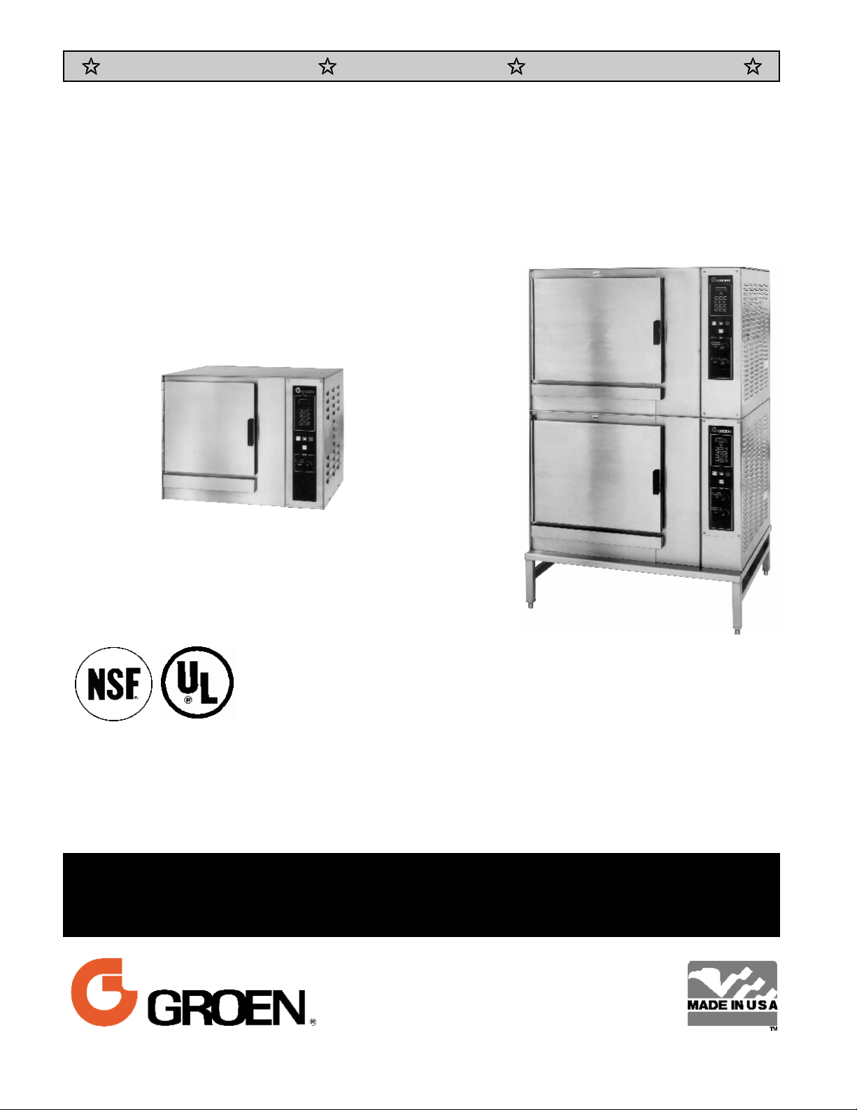
MODEL: CC-E
CONVECTION COMBO™
Combination Steamer-Oven
CC10-E
CC20-EF
THIS MANUAL MUST BE RETAINED FOR FUTURE REFERENCE. READ,
UNDERSTAND AND FOLLOW THE INSTRUCTIONS AND WARNINGS
CONTAINED IN THIS MANUAL.
FOR YOUR SAFETY
DO NOT STORE OR USE GASOLINE OR OTHER FLAMMABLE VAPORS AND
LIQUIDS IN THE VICINITY OF THIS OR ANY OTHER APPLIANCE
.
Information contained in this document is
known to be current and accurate at the time
of printing/creation. Unified Brands recommends referencing our product line websites,
unifiedbrands.net, for the most updated
product information and specifications.
Page 2

OM-CC-E
IMPORTANT — READ FIRST — IMPORTANT
WARNING:
CAUT ION: SHIPPING ST RAPS ARE UNDER T ENSION AND CAN SNAP BACK WHEN CUT .
CAUT ION:
CAUT ION:
WARNING: TO AVOID DAMAGE OR INJURY, FOLL OW T HE WIRING DIAGRAM EXACT LY WHEN
CAUT ION:
WARNING:
WARNING:
IM PORTANT:
IM PORTANT:
WARNING:
THE UNIT MUST BE INST ALLED BY PERSONNEL QUALIFIED TO WORK WITH ELECTRICITY
AND PLUM BING. IM PROPER INST ALLAT ION CAN CAUSE INJURY T O PERSONNEL AND/OR
DAMAGE TO THE EQUIPMENT. THE UNIT MUST BE INSTALLED IN ACCORDANCE WITH
APPLICABLE CODES.
DO NOT INSTAL L T HE UNIT IN ANY WAY WHICH WILL BLOCK T HE RIGHT SIDE VENT S,
OR WITHIN 12 INCHES OF A HEAT SOURCE SUCH AS A BRAISING PAN, DEEP FRYER,
CHAR BROILER OR KET T LE.
LEVEL THE UNIT FRONT TO BACK, OR PITCH IT SLIGHTLY TO THE REAR, TO AVOID
DRAINAGE PROBLEM S.
CONNECTING A UNIT .
DO NOT USE PLAST IC PIPE. DRAIN MUST BE RATED FOR BOILING WAT ER.
DO NOT CONNECT T HE DRAIN DIRECTLY T O A BUILDING DRAIN.
BLOCKING THE DRAIN IS HAZARDOUS.
Improper drain connection will void warranty.
Do not allow any water traps in the line. A trap can cause pressure to build up inside the
cavity during steaming, which will make the door gasket leak.
WHEN YOU OPEN THE DOOR, STAY AWAY FROM STEAM COMING OUT OF THE UNIT.
ST EAM CAN CAUSE BURNS.
WARNING: BEFORE CL EANING THE OUTSIDE OF THE ST EAMER, DISCONNECT THE ELECTRIC POWER
SUPPLY. KEEP WATER AND CLEANING SOLUTIONS OUT OF CONTROLS AND ELECTRICAL
COMPONENTS. NEVER HOSE OR STEAM CLEAN ANY PART OF THE UNIT.
WARNING:
WARNING:
WARNING:
WARNING: DO NOT PUT HANDS OR T OOLS INT O T HE COOKING CHAM BER UNTIL T HE FAN HAS
WARNING:
NOT ICE:
NOT ICE:
WARNING:
ALLOW COOKING CHAMBER T O COOL BEFORE CLEANING.
CAREFULLY READ T HE WARNINGS AND FOLLOW T HE DIRECTIONS ON THE LABEL OF EACH
CLEANING AGENT.
DELIM ING AGENT M ANUFACT URER.
DO NOT MIX DE-LIMING AGENT S (ACID) AND DE-GRE ASERS (ALKALI).
STOPPED TURNING.
DO NOT OPERATE THE UNIT UNLESS THE REMOVABLE RIGHT SIDE PANEL HAS BEEN
RET URNED T O IT S PROPER L OCATION.
DO NOT USE A CLEANING OR DE -LIMING AGENT THAT CONT AINS ANY SUL FAM IC ACID
OR ANY CHLORIDE, INCLUDING HYDROCHLORIC ACID. IF THE CHLORIDE CONT ENT OF
ANY PRODUCT IS UNCLEAR, CONSULT T HE MANUFACT URER.
DO NOT USE ANY DE-GREASE R THAT CONT AINS POTASSIUM HYDROXIDE OR SODIUM
HYDROXIDE OR THAT IS ALKALINE.
USE OF ANY REP LACEM ENT PARTS OT HER THAN T HOSE SUPPLIE D BY GROEN OR THEIR
AUTHORIZED DIST RIBUTOR VOIDS ALL WARRANTIES AND CAN RESULT IN BODILY INJURY
TO T HE OPERATOR AND DAMAGE T HE EQUIPMENT . SERVICE BY OTHER T HAN FACTORYAUTHORIZED PERSONNEL WILL VOID ALL WARRANTIES .
USE SAFETY GLASSES AND RUBBER GLOVES AS RECOMMENDED BY
WARNING:
HIGH VOLTAGE EXIS TS INSIDE CONTROL COMPART MENT S. DISCONNECT FROM BRANCH
BEFORE SERVICING. FAILURE TO DO SO CAN RESULT IN SERIOUS INJURY OR DEATH.
2
Page 3

Table of Contents
OM-CC-E
OPERATOR WARNINGS
REFERENCES ..........................................................3
EQUIPMENT DESCRIPTION
INSPECTION AND UNPACKING
WATER CONDITIONING/REQUIREMENTS .....................................6
INSTALLATION AND START-UP INSTRUCTIONS
OPERATING INSTRUCTIONS
CLEANING ............................................................21
MAINTENANCE
TROUBLESHOOTING
SERVICE LOG..........................................................30
........................................................
...................................................
................................................
.............................................
................................
..............................................
....................................................
2
4
5
7
13
24
25
WARRANTY PROTECTION
UNDERWRITERS LABORATORIES, INC.
333 Pfingsten Road
Northbrook, Illinois 60062
KLENZADE SALES CENTER
ECOLAB, Inc.
370 Wabasha
St. Paul, Minnesota 55102
800 328-3663 or 612 293-2233
................................................
31
References
NATIONAL FIRE PROTECTION
ASSOCIATION
60 Battery March Park
Quincy, Massachusetts 02269
NFPA/70 The National Electrical Code
NATIONAL SANITATION FOUNDATION
3475 Plymouth Road
Ann Arbor, Michigan 48106
3
Page 4
OM-CC-E
Equipment Description
Your Groen Convection Combo™ has a stainless
steel cooking chamber, an air heating compartment
with electric heating elements and fan, a steam
generator with electric heating elements, and a
control compartment which houses other electrical
components.
All major components of the Convection Combo™
are encased in a 16 gauge stainless steel cabinet.
Glass fiber insulation, lines the cabinet at a thickness
of 1½ to 2 inches (4 to 5 cm). A removable drip tray
is located beneath the door.
Door hinges are reversible so that doors may open
from the left or right side. Operator controls are
located on the right side of the front panel.
Standard controls let you to operate the Convection
Combo in any one of three cooking modes:
1. As a convection oven
2. As a self-contained, pressureless steamer
3. As a c ombination oven-steamer
Models CC10-E and CC20-E differ in cooking
chamber size and capacity:
CC10-E: 4 steam table pans (12x20x2½”), or
7 half-size (13x18") US baking pans
CC20-E: 10 steam table pans (12x20x2½”), or
9 full-size (18x26") US baking pans
The smaller Convection Combo™ is available as a
table-top unit (the single CC10-E). These units are
also supplied on a stainless steel stand as models
CC10-EF and (2)CC10-EF. The larger Convection
Combo™ is always supplied with a stand as the
single CC20-EF or the double-stacked (2)CC20-EF.
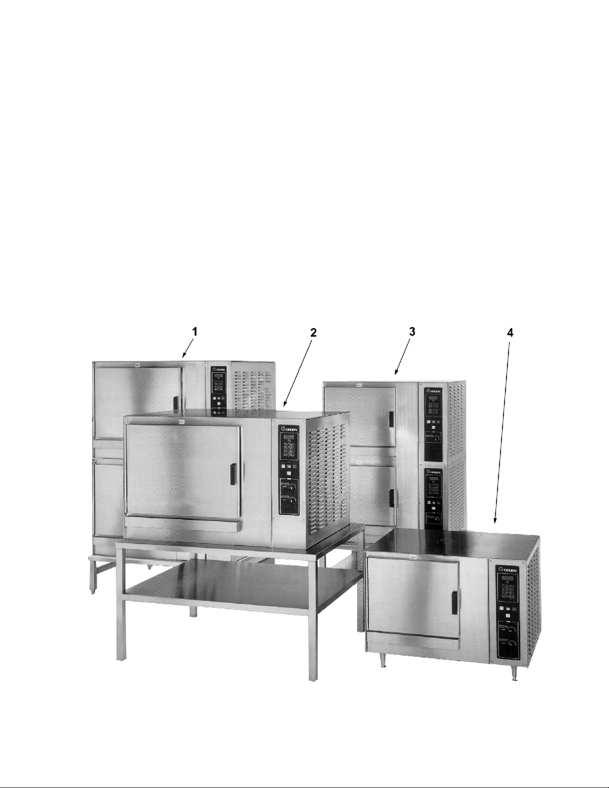
The Convection Combo™ Family: 1. Model (2)CC20-EF (Full-sized double-stacked unit on rigid stand),
2. Model CC-20-EF (Full-sized single unit on a convenient stand), 3. Model (2)CC10-EF (Double-stacked,
stand-mounted, half-pan Combo, 4. Model CC10-EL single four inch leg-mounted. (Also available in
tabletop (CC10-E) and stand-mounted (CC10-EF) versions.
4
Page 5

Inspection and Unpacking
OM-CC-E
Your Convection Combo™ will be completely
assembled in a heavy shipping carton or wooden
crate, and attached to a skid. On receipt, inspect
the carton or crate carefully for exterior damage.
CAUT ION
SHIPPING ST RAPS ARE UNDER T ENSION AND
CAN SNAP BACK WHEN CUT.
Carefully cut the straps around the carton and detach
the sides of the carton from the skid. Pull the carton
up off the unit. Be careful to avoid personal injury or
equipment damage from staples which might be left in
the carton walls.
Water Conditioning
It is essential to supply the steam generator with
water that will not form scale. Even though the
steam generator is engineered to minimize scale
formation, scale development depends on the
hardness of your water and the number of hours you
operate the equipment.
In some areas, water is low enough in mineral
content to avoid scale formation. But most water
supplies are full of minerals which form scale. It is
this scale which could lead to an early component
failure.
Your water utility can tell you about the minerals in
your water. The water going to the steam generator
should have between 30 and 40 parts per million
(ppm) total dissolved solids (TDS) and should have a
pH (acidity rating) of 7.0 to 9.0. Please follow these
simple precautions:
Do not rely on unproven water treatments
1.
which are sold for scale prevention or scale
removal. They don’t always work. The best
way to prevent scale is to supply the purest
possible water (30 -40 ppm TDS).
Write down the model number, serial number and
installation date and keep this information for future
reference. Space for these entries is provided at the
top of the Service Log in the back of this manual.
CAUT ION
THIS UNIT IS VERY HEAVY. YOU SHOULD GET
HELP AS NEEDED TO LIFT T HIS WEIGHT
SAFELY.
When starting installation, lift the unit straight up off
the skid. Check packing materials to make sure
loose parts are not discarded with the material.
softener will provide longer generator life, higher
steam capacity, and reduce maintenance
requirements.
If you notice a slowdown in steam production,
3.
have the unit checked for scale build-up. Heavy
scale reduces the unit’s ability to boil water, and
can even cause heating elements in the steam
generator to overheat and burn out.
MINIMIZE SCALE PROBLEM S, BY USING AND
MAINTAINING A SOFT ENER, AND BY CLEANING
THE STEAM GENERATOR REGULARL Y.
Groen Convection Combo™ ovens are also available
with an option for two separate water connections —
one for the steam generator (soft water), the other
for the spray condenser (untreated water). The
steam generator only uses 14 to 31% of a
combination oven’s water.
Since softener systems are typically sized by total
GPH (gallons per hour), the second connection could
reduce treatment requirements by up to 80%,
resulting in significant savings.
2. If your water contains scale-forming minerals, as
most water does, use a well-maintained water
softener. Whether an exchangeable softener
cartridge or a regenerating system is chosen, a
regular exchange schedule is essential.
Installing a water meter between the softener and
the steamer will provide an accurate gauge of water
use, and will help determine when to exchange
cartridges or regenerate the softener. Using a water
5
Page 6
OM-CC-E
Installation and Start-Up
WARNING
THE UNIT MUST BE INST ALLED BY PERS ONNEL WHO ARE QUALIFIED T O WORK WIT H ELECTRICITY AND
PLUM BING. IMPROPER INSTALLATION CAN CAUSE INJURY TO PERSONNEL AND/OR DAMAGE TO THE
EQUIPMENT. THE UNIT MUST BE INSTALLED IN ACCORDANCE WITH APPLICABLE CODES.
CAUT ION
DO NOT INSTALL THE UNIT WITH THE RIGHT SIDE VENTS BLOCKED OR WITHIN 12 INCHES OF A HEAT
SOURCE (SUCH AS A BRAISING PAN, DEEP FRYER, CHAR BROILER OR KET TLE). DO NOT INSTAL L T O
THE LEFT OF ANY OPEN-FLAME EQUIPMENT.
TO AVOID DRAINAGE PROBLEMS, LEVEL THE UNIT FRONT TO BACK.
A.MODEL CC10-E
Terminal block
1. Mounting
d.
If you wish to install a Convection Combo™ on
top of another, you should obtain a double
stacked unit from the factory.
If the unit does not have a factory-installed stand,
the installer must provide a table, stand or
counter which is strong enough to support the
unit. Use of casters is not recommended.
To avoid drainage problems, level the unit front
to rear, or provide a slight pitch to the rear.
Bolt the unit to the table, stand or counter top,
using the mounting holes in its base.
2. Electrical Supply Connections
Panel Removal
a.
The right side panel must be removed to gain
access to the wiring and control
compartment. Remove the two screws at
the bottom of the panel. Slide the panel
toward the front of the unit, lift it and set it
aside.
Supply Voltage
b.
The CC10-E must operate at the rated
nameplate voltage, plus or minus 10%.
Phase Select Plug (Units manufactured
c.
before 1996)
Locate the phase select plug assembly on
the wiring harness from the relay board.
This assembly is black, blue and red. Refer
to the labels located below the motor and
above the distribution block for the correct
phase connection.
The terminal block for incoming power is
located at the back of the control
compartment.
WARNING
WHEN CONNE CT ING FOR SINGLE PHASE
OPERAT ION, DO NOT CONNECT ANY WIRE TO
LINE 3 (T HE TERMINAL FART HEST LEFT ). T HIS
WILL CAUSE A SHORT CIRCUIT .
The ground terminal is found on the relay
bracket below the terminal block. The
Convection Combo™ must have a separate
ground wire for safe operation. The ground
wire must be at least 10 AWG (2.6 mm).
e. Supply Wire
The type of wire needed is determined by
finding the operating voltage and phase from
the unit’s back data plate and (on pre-1996
models) phase select connector. Refer to
the “Electrical Supply Connection” label on
the back of the unit for correct wire size and
insulation temperature rating.
The specified wire must be used to comply
with Underwriters Laboratories and National
Electric Code requirements.
The knockout hole is sized for a ¾ inch (19
mm) conduit fitting.
6
Page 7
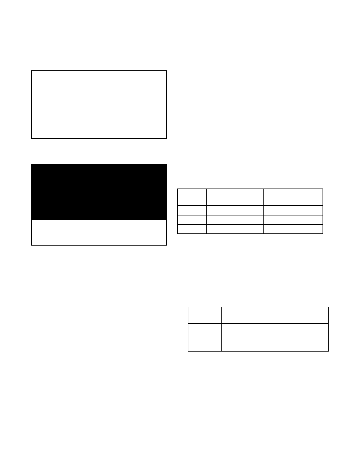
CC10-E ELECTRICAL SUPPLY CONNECTION
(All wires copper only.
Reference: National Electrical Code)
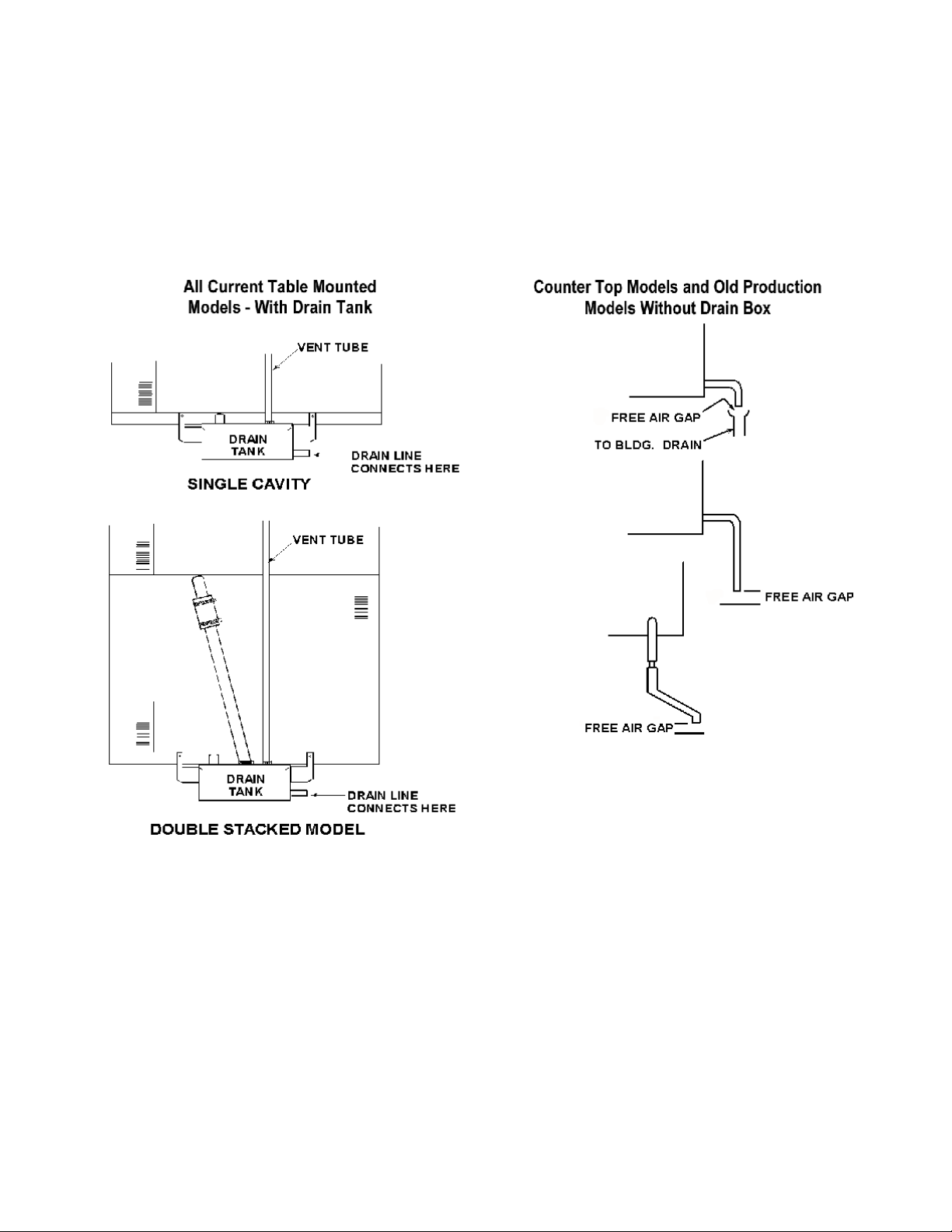
4. Drain Connection
CC10-E Without Drain Tank (tabletop model)
a.
OM-CC-E
Voltage Phase Wire Size Insulation
208 1 6AWG (4.1mm) 75oC
208 1 8AWG (3.3mm) 90oC
208 3 8AWG (3.3mm) 75oC
240 1 8AWG (3.3mm) 75oC
240 3 8AWG (3.3mm) 75oC
Branch Circuit Protection
f.
Groen strongly recommends that each
Convection Combo™ have its own branch
circuit protection. A double stacked unit should
have separate protection for the upper and
lower steamer-ovens.
CURRENT DEM AND
Voltage Current Power
1 Phase 3 Ph., per Line
208 44.7 A 27.5 A 9.3 KW
240 38.8 A 24.1 A 9.3 KW
Each current-carrying conductor must have
overcurrent protection. Refer to the label on
the back of the unit for proper wire size and
type. Watertight connections are required.
3. Water Supply Connection
A check valve (back siphonage device) must be
installed in the incoming cold water line in keeping
with local plumbing codes. Water line pressure
should be between 30 and 60 PSI (210 and 410
kPa). A pressure regulator is required above 60
PSI (410 kPa).
A ¾ inch (19 mm) NH (garden hose type)
connector is required to connect the water supply
to the water inlet valve. The water feed line
diameter may not be less that ½ inch (13 mm).
Use a washer (or if necessary, two washers) in the
hose connection. Do not allow the co nnection to
have any le ak, no matter how small.
A 1½ inch (4 cm) hose may be attached to the
provided drain elbow with a clamp. Do not use
plastic pipe. The drain must withstand boiling
water.
WARNING:
DO NOT CONNECT T HE DRAIN DIRECTLY T O A
BUILDING DRAIN.
There must be a free air gap between the end
of the hose and the building drain. The free air
gap should be as close as possible to the unit’s
drain. There must also be no other elbows or
othe r res trictions between the unit drain and the
two inch free air gap.
CAUT ION
DO NOT USE PLASTIC PIPE. DRAIN MUST BE
RATED FOR B OIL ING WAT ER.
WARNING
BLOCKING THE DRAIN IS HAZARDOUS.
Ins tall the drain line with a constant downward
pitch.
IMPORTANT: Do not allow any water traps in the
line. A trap can cause pressure to build up inside
the cavity during steaming, which will make the
door gasket leak.
NOT E: Improper drain connection will void the warranty.
b. CC10-E With Drain Tank
A 1½ inch (4 cm) ID hose may be attached to
the supplied drain elbow with a clamp. The
hose may be connected directly to a building
drain since the drain tank has an air vent, which
eliminates the need for a free air gap at the
building drain. Do not block the air vent in any
way. Do not attach anything to the vent tube or
reduce its size.
Do NOT use plastic pipe in the drain line,
because the drain must withstand boiling water.
If your CC10-E is equipped with the optional split
water supply, the supply for each steam generator
must be able to fill the generator with 1½ gallons
(5.7 liters) or water in 1½ minutes. The make-up
water rate is 0.06 gallons per minute (0.2 liters per
minute). Condensate spray water rate is 0.34
gallons per minute (1.3 liters per minute) at 30 PSI
(210 kPa).
7
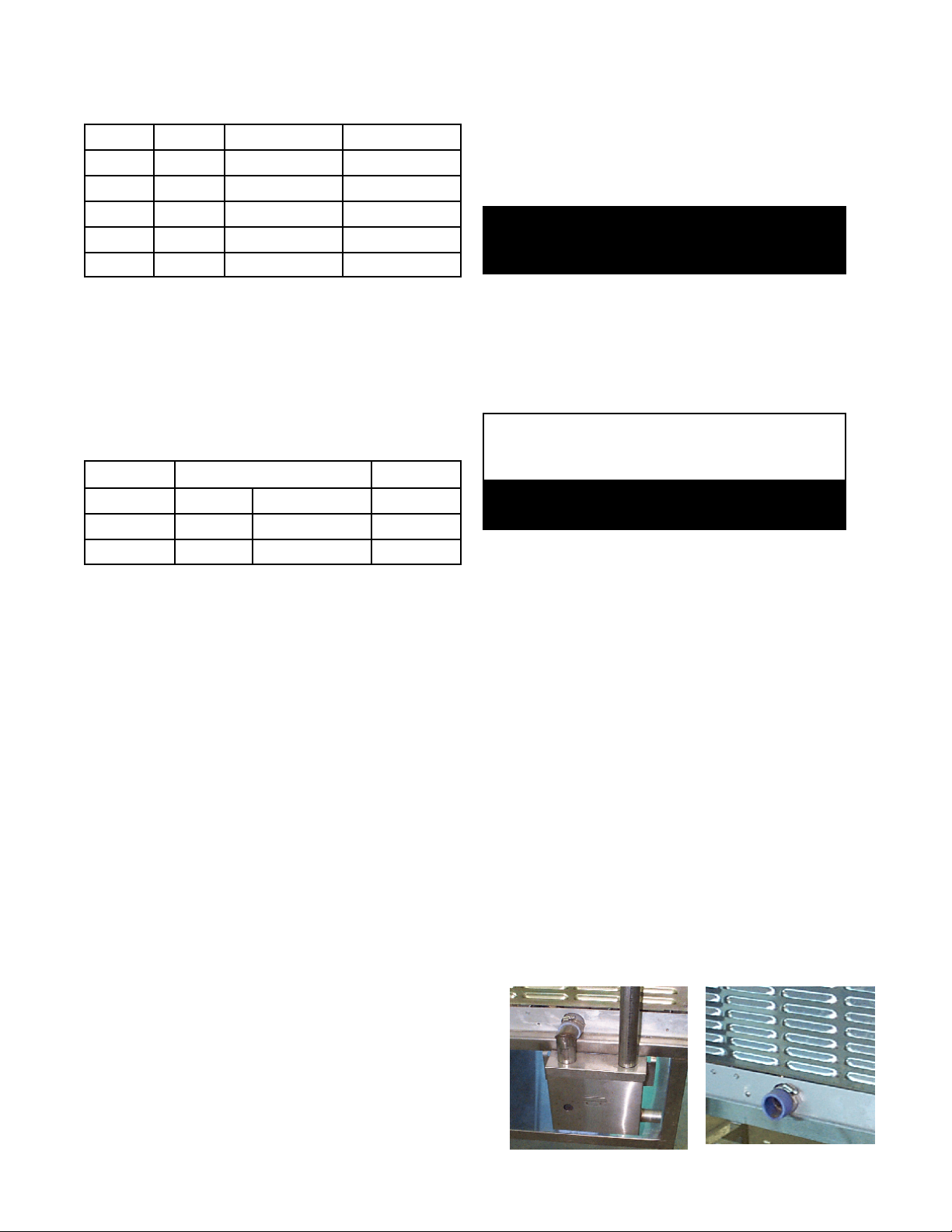
Drain Tank
Tabletop Model
Page 8
OM-CC-E
Proper Drain Line Connections
8
Page 9
B.MODEL CC20-E
Mounting
1.
If you wish to install one Convection Combo™
above another, obtain a double-stacked unit from
the factory.
CAUT ION
DO NOT INSTAL L A CC20-E IN ANY LO CATION
WHERE RIGHT SIDE VENTS ARE BLOCKED, OR
WIT HIN 12 INC HE S OF A HEAT SOURCE SUCH
AS A BRAISING PAN, DEEP FRYER, CHAR
BROILER OR KETT LE.
DO NOT INSTALL THE UNIT TO THE LEFT OF
ANY OPEN FLAME EQUIPMENT.
OM-CC-E
breaker or 10 AWG (2.6 mm) for a 40 to 60
amp breaker.
d. Supply Wire
The type of wire needed is determined by
finding the operating voltage and phase from
the unit’s back data plate and phase select
connector. Refer to the “Electrical Supply
Connection” label on the back of the unit for
correct wire size and insulation temperature
rating.
The specified wire must be used to comply
with Underwriters Laboratories and National
Electric Code requirements.
To avoid drainage problems, level the unit frontto-rear, or provide a slight pitch to the rear.
WARNING
THE UNIT MUST BE INSTALLED BY
PERSONNEL QUALIFIED TO WORK WITH
ELECTRICITY AND PLUMBING. IMPROPER
INSTAL LATION CAN CAUSE INJURY TO
PERSONNEL AND/OR DAMAGE TO
EQUIPMENT.
CAUT ION
INSTALLAT ION MUST BE IN ACCORDANCE
WITH ALL APPLICABLE CODES.
Electrical Supply Connections
2.
a. Panel Removal
The right side panel must be removed to gain
access to the wiring and control
compartment. Remove the screw at the
back of the panel. Slide the panel toward
the front of the unit, lift it and set it aside.
b. Supply Voltage
The CC20-E must operate at the rated
nameplate voltage, plus or minus 10%.
c. Terminal block
The terminal block for incoming power is
located at the back of the control
compartment.
The knockout hole is sized for a one inch
(25.4 mm) conduit fitting.
CC20-E ELECTRICAL SUPPLY CONNECTION
(All wires copper only.
Reference: National Electrical Code)
o
Voltage
208 4 AWG (5.2 mm) 6 AWG (4.1 mm)
240 4 AWG (5.2 mm) 6 AWG (4.1 mm)
480 8 AWG (3.3 mm) 8 AWG (3.3 mm)
e. Branch Circuit Protection
Voltage
Size for 75
(T HWN)
Groen strongly recommends that each
Convection Combo™ have its own branch
circuit protection. A double stacked unit
should have separate protection for the
upper and lower steamer-ovens.
CURRENT DEM AND
208 65.4 A 21 KW
240 56.7 A 21 KW
480 28.3 A 21 KW
Each current-carrying conductor must have
overcurrent protection. Refer to the label on
the back of the unit for proper wire size and
type. Watertight connections are required.
C
Current per line
(Three Phase)
Size for 90oC (THHN)
Power
The ground terminal is found below the
terminal block. The Convection Combo™
must have a separate ground wire for safe
operation. The ground wire must be at least
8 AWG (3.3 mm) for a 100 amp circuit
Water Supply Connection
3.
A check valve (back siphonage device) must be
installed in the incoming cold water line in
keeping with local plumbing codes. Water line
pressure should be between 30 and 60 PSI (210
9
Page 10

OM-CC-E
and 410 kPa). A pressure regulator is required
above 60 PSI (410 kPa).
A ¾ inch (19 mm) NH (garden hose type)
connector is required to connect the water supply
to the water inlet valve. The water feed line
diameter may not be less that ½ inch (13 mm).
Use a washer (or if necessary, two washers) in
the ho se connection. Do not allow the
connection to have any leak, no matter how
small.
Drain Connection
4.
CAUT ION
DO NOT USE PLAST IC PIPE. DRAIN MUST BE
RATED FOR B OIL ING WAT ER.
WARNING
BLOCKING THE DRAIN IS HAZARDOUS.
IMPORTANT: Do not allow any water traps in the
line. A trap can cause pressure to build up
inside the cavity during steaming, which will
make the door gasket leak.
NOT E: Improper drain connection will void the
warranty.
CC20-E With Drain Tank
A two inch (51 cm) ID hose may be attached to
the supplied drain elbow with a clamp. The hose
may be connected directly to a building drain
since the drain tank has an air vent, which
eliminates the need for a free air gap at the
building drain.
Do not block the air vent in any way. Do not
attach anything to the vent or reduce its size.
Do NOT use plastic pipe in the drain line,
because the drain must withstand boiling water.
10
Page 11

OM-CC-E
Initial Start-Up
WARNING
ANY POT ENT IAL USER OF THE EQUIPM ENT SHOULD BE TRAINE D IN SAFE AND CORRECT OPERATING
PROCEDURES.
After the Convection Combo™ has been installed,
test it to ensure that it is operating correctly.
Remove all literature and packing materials from
1.
the interior and exterior of the unit.
2. Check that the cold water supply line is open and
that none of the f ittings are leaking.
Turn on electrical service to the unit.
3.
High Altitude Operation. At altitudes above
4.
5,000 feet (1524m), the unit will not operate in
the Steamer or Combo Modes unless the altitude
is set. You can program the altitude as follows:
a. If the unit is on, turn it off by pressing the ON
touc h pad.
b. Press and hold the STEAM touch pad while
turning the unit on by pressing the ON touch
pad. The Timer Display will show the letters
AL and a number representing the altitude in
thousands of feet. If the altitude has not
been set for your unit, the display will be 0.
c. Enter an altitude value between 0 and 15,
using the numbered touch pads. For
example, if the unit will be operating at 7,000
feet, enter 7.
For CC20-E only: Check Fan
5.
Rotation — IMPORT ANT ! As
seen from inside the oven cavity,
the fan should be turning in a
counterclockwise direction. If the
fan is running backwards
(clockwise), have a qualified
electrician turn off the main power and switch
any two incoming power leads on the distribution
block. An incorrectly turning fan will eventually
shut the oven down.
Select Farenheit or
6.
Celsius
Temperatures. The
Convection Combo™
is delivered with the
Farenheit scale as
default. To c hange
the current
temperature scale,
holding the 5 key in,
press ON. The Timer
Display will either
show dEG°F or
dEG°C. Press the 5
key again to change
from one to the other. Press START to accept
the change.
d. Press the START touch pad.
Altitude Metric Conversion
Altitude
Feet Meters
5000 1524 5
6000 1830 6
7000 2133 7
8000 2438 8
9000 2745 9
10000 3048 10
11000 3353 11
12000 3658 12
13000 3962 13
14000 4267 14
15000 4572 15
Setting
11
To Test Steamer Mode Operation, turn on the
7.
unit. (For details of operating procedure, see the
Operation section of this manual.) Clear time
from the time display. Press the STEAM touch
pad. (If the HOT light is on, see the Fast Cool
instructions in the Operation section.)
The WAIT light will stay on while the steam
generator fills with and heats the water. The
WAIT light should turn off within three minutes,
and the READY light should come on. This
indicates that the water is at its standby
temperature. The timer only controls operations
in the Steamer Mode. Enter a time and press
ST ART. (“Time” is set in minutes and hours
only. Seconds are not displayed).
Examples: 2 minutes = 00:02
(Just press 2).
1 hour and 30 minutes = 01:30
(Press 1, 3, and 0, or press 9,0
the timer will change to 1:30)
Page 12

OM-CC-E
The colon [:] between the numbers on the time
display will blink and the generator will begin to
produce steam. The time will not count down
unless the READY light is lit.
NOT E: You cannot chang e modes if the timer is
running.
8. To Test Combo Mode Operation, turn on the
power and clear any time from the timer display.
Press the COMBO touch pad. Set the COOK
temperature to 300
will come on. It will remain on while (1) the
steam generator fills with water and heats it to
its standby temperature and (2) the air heater
raises the air temperature to 300
actions should be completed in about five
minutes, starting with a cold unit. When the set
temperature is attained, the WAIT light will go
off, and the READY light will come on.
NOT E: The timer does not control the oven in
either the Combo or Oven Modes.
o
F (150oC). The WAIT light
o
F. Both
To Test Oven Mode Operation, turn on the
9.
power and clear the timer display. Press the
OVEN touch pad. Set the cook temperature to
o
F (175oC). The WAIT light will come on.
350
Within six minutes from a cold start, the WAIT
light should go out and the READY light should
come on. When that happens, turn the COOK
temperature setting down to 320oF (160oC). The
HOT light will come on.The heat-up times
provided above may vary slightly as a result of
voltage or water pressure differences.
To shut down the unit, first clear the timer. Next,
10.
press the mode pad for the mode in which the
unit is operating. Finally, switch off the power.
11. If your Convection Combo™ behaves as
described, the unit is functioning correctly, and is
ready for use.
12
Page 13

OM-CC-E
Operation
WARNING
ANY POT ENT IAL USER OF THE EQUIPM ENT SHOULD BE TRAINE D IN SAFE AND CORRECT OPERATING
PROCEDURES.
Controls and Indicators
A.
Operator controls features are on the right front side
of the unit. Their use is described below:
1. Time Section
In Oven and Combo Modes, the timer
func tions only as a “cooking time minute
minder” and does not turn the unit on or off.
In the Steamer Mode, however, it controls
the steaming function.
a. Display Window — Shows operating
time remaining in the Steamer, Oven or
Combo Mode. The timer counts down.
If the unit is equipped with, and operating
in the optional Hold Mode, the timer will
count up, and will show the total
accumulated time that the product has
been holding. The window shows
operating time in “hours:minutes” format.
For example, entering 9 and 0 will result
in a display of 01:30. (On some older
units numbers higher than 59 will not be
accepted - in these cases, convert the
time to hours and minutes. 90 minutes
would be entered 1,3, 0.
beeper will sound and the SERVICE light
will be on when you switch on the power.
The unit may continue to operate,
depending on the type of problem.
Refer to the Troubleshooting section to
determine the nature of the problem.
b. Time touch pads — used to enter time
values .
c. CLEAR — Pressing this touch pad once
stops the beeper and resets the timer to
the time that was last set. Pressing
twice clears it to 00:00. At the end of a
cooking period, opening the door is the
same as pressing CLEAR once.
d. ST ART — Press this touch pad to start
the timer. If the unit is in Steamer Mode,
it will also cause steaming to begin.
2. Status Lights
a. HOT — Indicates chamber temperature
is more than 15
temperature. (See Paragraph 5 in this
section)
b. SERVICE — Indicates that there is a
problem which might require a service
call. If there is such a problem the
o
F (8oC) over the set
13
Page 14

OM-CC-E
c. WAIT — Indicates the unit is either
d. READY — Indicates the unit is ready for
Cooking Mode Selection
3.
a. STEAM — Selects steamer operation
b. COMBO — Selects superheated steam
c. OVEN — Selects convection oven
4. Power
The ON touch pad turns the unit on or off.
When power is on, the ON light just above
the touch pad is lit. Use of this pad does not
reset the controls. The unit will always come
on in the same mode it was in when shut
down.
heating or cooling toward the set
temperature. The HOT and WAIT lights
will both be on if the chamber is more
than 15
o
F (8oC) above the set point.
use.
only.
and convection oven operation.
operation only.
5. Temperature (TEMP) Section
a. The Temperature Display Window shows
the selected temperature in either Oven
or Combo Mode. It is blank in the
Steamer Mode or when the optional Hold
Mode is operational.
b. Turning the Temperature Control Knob
selects the cooking temperatures in 5
increments. The control ranges are:
Oven Mode 200-575oF (95-300oC)
Combo Mode 220-575oF (105-300oC)
Optional HOLD Section
6.
This optional feature permits low
temperature holding or (on models built
before November 1996) proofing with
controlled humidity, when the unit has
already been set in the Oven or Combo
Mode. Whether Oven or Combo Mode has
been selected has no effect on this optional
feature’s operation. Hold Mode controls are
located at the bottom of the control panel.
o
F
a. The upper window shows the selected
holding temperature. This display is
blank when the Hold Mode has been
turned off.
14
Page 15

b. Turning the Hold Control Knob clockwise
activates the Hold Mode and sets
temperatures in 5oF increments within a
range of 90oF to 200oF (30 to 95oC).
The OVEN or COMBO mode light must
be on before Hold Mode can operate.
c. On units with the Hold Option which
were manufactured before November
1996, there is a lower window which
displays the selected humidity. If the
Hold Mode is turned off, it will be blank.
d. Pressing the humidity set touch pad on
these units selects the relative humidity
Available choices for humidity settings
are LO; 45, 50, 55, 60, 65, 70, or 80%;
and HI.
Operating Instructions
B.
1. Steamer Mode
a. If the unit is off, switch on the electric
power by pressing the ON touch pad. (If
the SERVICE light comes on when you
turn on the power, see the
Troubleshooting section).
OM-CC-E
WARNING
WHEN YOU OPEN THE DOOR STAY AWAY
FROM ANY STEAM COMING OUT OF T HE
UNIT. STEAM CAN CAUS E BURNS.
e. The WAIT light will be on until the water
reac hes 200oF (93oC). It will then turn
off and the READY light will come on.
You are now ready to steam foods in
your Convection Combo™.
f. Load the food into pans in an even,
b. If the power is already on, and there is a
number in the time display window,
press the CLEAR touch pad one or more
times to reset the time to zero.
NOT E: You cannot change operating
modes while the timer is running
c. The unit will power up in the mode of
operation in which it was last used.
Because of this, the indicator light for
that mode will be lit. If the unit is not
already in the Steamer Mode, press the
STEAM touch pad. The STEAM light
will come on and the Temperature
Window will go blank.
d. If the unit was recently used in Oven or
Combo Mode, the HOT light may come
on, indicating that the cooking chamber
is too hot for use as a steamer. The unit
can be cooled quickly to the steaming
temperature range by leaving the door
open or following the Fast Cool
procedure described near the end of this
section (Paragraph 5). With the door
open the generator can fill and heat the
water to 200
steam.
o
F, but it cannot produce
uniform layer.
g. Carefully open the door and slide the
pan or pans onto the pan racks in the
cooking chamber. If you are only using
one pan, place it in the middle position.
Close the door.
h. Press the numbered touch pads to set
the cooking time. The time will appear in
the Time Display Window. If you enter
the wrong number, press the CLEAR
touch pad to erase the time from the
display, and enter the time again.
i. When the correct cooking time has been
entered, press the ST ART pad. The
colon in the display will blink and the time
will count down the cooking time. (The
unit must be READY before the timer
can count down.
j. If you open the door during the cooking
period, steaming and the timer will stop
(but will not reset). When you close the
door, steaming and timing will continue.
15
Page 16

OM-CC-E
WARNING
WHEN YOU OPEN THE DOOR STAY AWAY
FROM ANY ST EAM COMING OUT OF T HE UNIT.
ST EAM CAN CAUSE BURNS.
number keys when you first use set that
time.
n. After the display has counted down to
zero you can reset the time to zero by
either (1) opening the door and pressing
CLEAR or pressing CLEAR twice. A
new cooking time may then be set by
using the number keys.
2. Oven Mode
a. To use the Convection Combo™ as a
convection oven, first switch on the
electric power by pushing the ON touch
pad. (If the SERVICE light comes on
when you turn on the power, see the
Troubleshooting section). If the door is
closed and the cooking temperature is
above 200
o
F (93oC) the fan will begin to
operate.
b. If the power is already on, and there is a
number in the time display window,
press the CLEAR touch pad one or more
times to reset the time to zero.
When the timer reaches zero, it stops steam
k.
generation and sounds a beeper alarm. Water in
the steam generator stays at its standby
temperature (200
o
F - 93oC). On some older
models, the beeper will continue to sound until
the door is opened or the CLEAR pad is
pressed.
l. Carefully open the door. If the food is
cooked, remove the pans using hot pads
or oven mitts to protect your hands from
the ho t pans.
m. After the display has counted down to
zero opening the door or pressing
CLEAR once
will reset the display to the
time that was last used. Pressing
ST ART will repeat the cook cycle. If the
NOT E: You cannot change operating
modes while the timer is running
c. The unit will power up in the mode of
operation in which it was last used.
Because of this, the indicator light for
that mode will be lit. If the unit is not
already in the Oven Mode, press the
OVEN touch pad. The OVEN light will
come on and the oven fan will operate.
d. Use the Temperature Control Knob to
set the desired cooking temperature,
which will appear in the temperature
display window. Unless the cooking
chamber is already at or above the
selected temperature, the unit will begin
heating and the WAIT light will come on.
same cooking time will be used
repeatedly, you only need to press the
16
Page 17

e. If the unit was recently used at a
temperature more than 15oF (8oC) higher
than the temperature selected, the HOT
and WAIT lights will turn on. The unit can
be cooled quickly to the desired cooking
temperature by leaving the door open or
following the Fast Cool procedure
described near the end of this section
(Paragraph 5).
f. The READY light will indicate when the
oven is at the desired temperature.
OM-CC-E
k.
To stop cooking, take the pans out of the
oven using hot pads or oven mitts to
protect your hands from the hot pans.
The unit will continue heating to keep the
chamber at the set temperature until the
temperature control is reset, or the power
is shut of f.
g. Load the food into the pan or pans in a
uniform layer.
h. The Convection Combo™ will operate in
Oven Mode with the timer either on or off.
If you want to time the cooking, press the
numbered pads in the TIME portion of the
control panel to set the cooking time. The
time will appear in the Time Display
Window. If you enter the wrong number,
press the CLEAR touch pad to erase the
time from the display, and enter the time
again. Remember that the timer does not
control the unit in the Oven Mode.
i. Open the door and slide the pan or pans
onto the pan racks in the cooking chamber.
If you are only using one pan, place it in
the middle position. Close the door.
j. If the correct time has been set on the
timer, press the ST ART pad. The colon [:]
between the numbers in the display will
blink and the time will count down the
cooking time. W hen the timer has counted
down to zero, it will sound a beeper. This
sound will continue until the door is opened
or the CLEAR pad is pressed.
WARNING
PANS AND INT ERNAL PARTS OF THE OVEN
WILL BE VERY HOT . AV OID C ONT ACT WITH
HOT SURFACE S.
l. Opening the door during operation shuts
of f power to the heaters and fan and
stops the timer, but it has no other affect
on the controls. When the door is closed,
operation continues. Note that cooking
time will be extended by the period the
door was open.
3. Combo Mode
a. If the unit is off, switch on the electric
power by pressing the ON touch pad. (If
the SERVICE light comes on when you
turn on the power, see the
Troubleshooting section). If the door is
closed and the cooking temperature is
above 200
o
F (93oC) the fan will begin to
operate.
b. If the power is already on, and there is a
number in the time display window, press
the CLEAR touch pad one or more times
to reset the time to zero.
17
NOT E: You cannot change operating
modes while the timer is running
c. The unit will power up in the mode of
operation in which it was last used.
Because of this, the indicator light for that
mode will be lit. If the unit is not already
in the Combo Mode, press the COMBO
touch pad. The COMBO light will come
on and if the steam generator is not
already full, water will flow into it and
begin heating.
d. Use the Temperature Control Knob to set
the desired oven temperature between
220 and 575
o
F (105 to 300oC). The
temperature will appear in the
temperature display window.
Page 18

OM-CC-E
e. If the unit was recently used at a
temperature more than 15oF (-8oC) higher
than the temperature selected, the HOT
and WAIT lights will turn on. The unit can
be cooled quickly by leaving the door open
or following the Fast Cool procedure
described near the end of this section
(Paragraph 5).
WARNING
WHEN YOU OPEN T HE DOOR STAY AWAY
FROM ANY ST EAM COMING OUT OF T HE UNIT.
ST EAM CAN CAUSE BURNS.
f. The WAIT light will be on until the water in
the steam generator reaches the boiling
point and the air in the cooking chamber
reaches the set temperature. It will then
turn off and the READY light will come on
indicating that the oven is at the desired
temperature.
i. Open the door and slide the pan or pans
onto the pan racks in the cooking
chamber. If you are only using one pan,
place it in the middle position. Close the
door.
j. If the timer has been set, press the
ST ART pad. The colon [:] between the
numbers in the display will blink and the
time will count down the cooking time.
When the timer has counted down to
zero, it will sound a beeper. This beeping
will continue until the door is opened or
the CLEAR pad is pressed.
k. To stop cooking, take the pans out of the
oven using hot pads or oven mitts to
protect your hands from the hot pans.
The unit will continue steaming and
heating the oven at the set temperature
until the temperature control is re set, or
the power is shut off.
Hold Mode (Cook-n-Hold Option) - (Cook-n-
4.
Hold/Proofing Option on Models Manu-
g. The unit will operate in Combo Mode with
the timer either on or off. If you want to
time the cooking, press the numbered
pads in the TIME portion of the control
panel to set the cooking time. The time
will appear in the Time Display Window. If
you enter the wrong number, press the
CLEAR touch pad to erase the time from
the display, and enter the time again. The
timer does not control the unit in Combo
Mode.
h. Load the food into the pan or pans in a
uniform layer.
WARNING
WHEN YOU OPEN THE DOOR ST AY AWAY FROM
ANY ST EAM COMING OUT OF THE UNIT. STEAM
CAN CAUSE BURNS.
factured Before November 1996) Items
identified by an asterisk (*) and/or in italics pertain
to Humidity Control features on some models
manufactured prior to November 1996.
18
Page 19

a. If these optional features are included in
your Convection Combo,™ the controls are
located near the bottom of the Control
Panel. Hold Mode may be activated when
the oven is either in Combo or Oven Mode,
and works the same in both.
b. If you want your Convection Combo™ to
switch to Hold Mode automatically when it
finishes cooking, use the following
procedure:
1) Set the unit for Combo or Oven Mode.
2) Set COOK temperature.
OM-CC-E
NOT E: Food will continue to be cooked
by the excess heat as the unit
slows to the set HOLD
temperature. The amount of
additional cooking depends on
the food product and the initial
COOK temperature.
The oven will operate at the set HOLD
temperature (and humidity)* until it is
changed or turned off. If desired, you
may check the time on hold by pressing
ST ART. The unit will count up and
display the time elapsed since it has been
holding. The maximum that the timer is
able to display is 19 hours and 59
minutes. After that the display will flash
19:59, but the unit will continue to
maintain the HOLD settings.
c. To end manual operation of the Hold
Mode, first remove the food from the unit.
Then take either of the following steps:
1) If the timer is not running, turn the
COOK temperature set knob
clockwise until a number appears in
the COOK temperature display. (The
unit will heat to the COOK setting).
2) If the timer is running, press and hold
in the CLEAR touch pad for at least
two seconds.
3) Set the cooking time.
4) Turn the HOLD temperature set knob
until the desired hold temperature
appears in the HOLD temperature
display.
5) (Press HUM IDIT Y set touch pad until
the desired setting appears in the
HUM IDITY display).*
6) After the READY light comes on to
indicate the oven is at the set
temperature, open the door, load food
into the unit and close the door.
7) Press the ST ART touch pad.
When the set cook time is ended, the unit
will automatically switch to the Hold Mode.
The beeper will NOT sound. The timer
will now count UP. The COOK
temperature display will be blank and the
temperature of the unit will slowly drop to
the HOLD temperature setting.
19
Page 20

OM-CC-E
5. Fast Cool
Shutting Down
6.
a. When the HOT indicator is lit and the
timer is cleared, the unit can be cooled
quickly by opening the door and
pressing ST ART . The fan will
operate, and the TIME window will
display the word “COOL.” This is the
only time the fan operates with the
door open.
WARNING
DO NOT PUT HAND S OR OT HER OBJECT S
INTO T HE COOKING CHAMBER DURING THE
FAST COOL OPERATION. T HE ROTATING FAN
CAN BE HAZARDOUS.
b. To stop the Fast Cool operation, press
any touch pad or close the door.
a. Press the touch pad for the mode in which
the unit is operating.
b. Switch off the power by pressing the ON
touc h pad.
Leave the door at least partially open, if local
sanitation regulations permit.
20
Page 21

OM-CC-E
Cleaning
To keep your Convection Combo™ in proper operating condition and to make the cleaning process easier, cleaning
should be a daily activity.
Suggested Tools and Cleaners
A.
1. Mild detergent
2. Stainless steel exterior cleaner such as
Zepper®
3. Steam generator de-liming agent, such as
Groen Delimer Descaler, Lime-Away®
or an equivalent. A liquid de-liming agent
will be easier to use than crystals or
powders. See the warning about chlorides
below.
4. De-greaser, s uch as EncompasS®, Malone
34®, Puritan Puribrute®, or Con-Lie®
5. Cloth or sponge
Plastic wool or a brush with soft bristles
6.
Spray bottle
7.
8. Measuring cup
9. Nylon pad
10. Towels
Plastic disposable gloves
11.
Procedure
B.
1. Exterior Cleaning
a. Prepare a warm solution of the mild
detergent as instructed by the supplier. Wet
a cloth with this solution and wring it out.
Use the moist cloth to clean the outside of
the unit. Do not allow freely running liquid to
touc h the contro ls, the control panel, any
electrical part, or any open louver.
To remove material which may be stuck to
b.
the unit, use plastic wool, a fiber brush, or
a plastic or rubber scraper with a
detergent solution.
Stainless steel surfaces may be polished
c.
with a recognized stainless steel cleaner
such as Zepper®.
DISCONNECT THE POWER SUPPLY
BEFORE CL EANING THE OUTSIDE OF
THE UNIT.
KEEP WATER AND CLEANING
SOLUT IONS OUT OF CONTROLS AND
ELECTRICAL COMPONENTS. NEVER
HOSE OR STEAM CL EAN ANY PART
OF THE UNIT.
DON’T MIX DE-LIMING AGENTS (ACID)
WITH DE-GREASERS (ALKALI)
ANYWHERE IN THE UNIT
AVOID CONT ACT WIT H ANY
CLEANERS, DE-LIMING AGENT OR DEGREASER AS RECOMMENDED BY THE
SUPPLIER. M ANY ARE HARMFUL.
READ THE WARNINGS AND FOLLOW
THE DIRECTIONS!
EVEN WHEN THE UNIT HAS BEEN
SHUT OFF, DON’T PUT HANDS OR
TOOLS INTO THE COOKING
CHAM BER UNTIL T HE FAN HAS
STOPPED TURNING.
DON’T USE ANY CL EANING OR DELIMING AGENT THAT CONT AINS ANY
SULFAM IC AGENT OR ANY CHLORIDE,
INCLUDING HYDROCHLORIC ACID
(HCl). TO CHECK FOR CHLORIDE
CONTENT SEE ANY MATERIAL
SAFETY DATA SHEETS PROVIDED BY
THE CLEANING AGE NT
MANUFACTURER.
UNIT MAY BE HOT. TAKE
PRECAUTIONS TO PREVENT
CONTACT WITH HOT SURF ACES.
PRECAUT IONS
WARNING
IM PORTANT
DO NOT USE ANY M ET AL MATERIAL (SUCH AS METAL SPONGES) OR METAL IMPLEMENTS (SUCH AS
A SPOON, SCRAPER OR WIRE BRUSH) THAT MIGHT SCRATCH THE SURFACE. SCRATCHES MAKE THE
SURFACE HARD TO CLEAN AND PROVIDE PLACES FOR BACTERIA TO GROW. DO NOT USE STEEL
WOOL, WHICH MAY LEAVE PARTICLES IMBEDDED IN THE SURFACE WHICH COULD EVENTUALLY
CAUSE CORROSION AND PITTING.
21
Page 22

OM-CC-E
Interior Cleaning
2.
To exit the Clean Cycle at any time, press and
hold the CLEAR touch pad. Be sure to wash
out all chemical residues thoroughly before
using the unit.
WARNING
UNIT MAY BE HOT . DO NOT T OUCH HOT
SURFACES.
DO NOT PUT HAND S OR OT HER OBJECT S
INTO COOKING CHAMBER WHILE CONVECTION
COMBO™ IS OPERATING. T HE ROT ATING FAN
CAN BE HAZARDOUS.
a. Turn off all operating modes by stopping the
timer, and pressing the mode touch pad(s).
b. Enter 99 on the timer. The display should
show “00:99.”
c. If the HOT light is on, use the Fast Cool
method to reduce the temperature
(Paragraph 5, Operation, Page 18). If the
HOT light is off, “CI” will be displayed in the
timer window, and you may proceed to the
next step.
Remove all pan racks and clean them in a
d.
sink. To remove the right side rack, lift it up
and to the left.
Remove the right side of the cooking
e.
chamber.
Prepare oven degreaser as directed on the
f.
product label. Thoroughly coat all inside
surfaces of the cooking chamber and both
sides of the right side panel with the
degreaser.
It may cause the unit to display false service
messages.
Replace the generator cover and right side
i.
panel in their normal positions.
Close the door and press START . The timer
j.
will display “CL:50,” with the colon [:]
between the numbers flashing. The timer will
count down to “CL:26.”
k. When the buzzer sounds and the timer
displays “C2,” open the door.
WARNING
THE UNIT WILL BE HOT ENOUGH TO CAUSE A
BURN. DO NOT TOUCH ANY HOT SURFACE.
l. Remove the right side panel and steam
generator cover and rinse them in the sink.
l. Rinse and wipe down the cooking chamber
with a cloth and plenty of clean water. Rinse
the cloth often.
n. Add de-liming agent to the steam generator
as specified by the de-liming agent label.
o. Put the generator cover and right side panel
back in place.
p. Close the door. The timer will display
“CL:26" and count down automatically to
“CL:00.”
q. Press the ON switch to turn off the unit. Let
the unit cool.
Remove the steam generator cover.
g.
NOT E:
h. If there are grease deposits in the generator,
Add degreaser to the steam generator
only if you see grease deposits.
add ¼ to ½ cup (60 to 125 ml) of full
strength degreaser to the generator, or
lightly coat the generator with spray
degreaser. Do not use too much degreaser.
22
WARNING
UNIT MAY BE HOT . DO NOT T OUCH HOT
SURFACES.
Remove the right side panel and steam
r.
generator cover and rinse them thoroughly in
a sink.
Page 23

Rinse and wipe down the cooking chamber
s.
with a cloth and plenty of clean water. Rinse
the cloth often.
3. De-liming Only
If you only want to clean hard, white deposits out of
the steam generator, it is not necessary to degrease
the unit.
a. Turn off all operating modes by stopping the
timer, and pressing the mode touch pad(s).
Enter 99 on the timer. The display should
b.
show “00:99.”
c. If the HOT light is on, use the Fast Cool
method to reduce the temperature
(Paragraph 5, Operation, Page 18). If the
HOT light is off, “CI” will be displayed in the
timer window, and you may proceed to the
next step.
OM-CC-E
Press the ON switch to turn off the unit. Let
k.
the unit cool.
WARNING
UNIT MAY BE HOT . DO NOT T O UCH HOT
SURFACES.
l. Remove the right side panel and steam
generator cover and rinse them thoroughly in
a sink.
m. Rinse and wipe down the cooking chamber
with a cloth and plenty of clean water. Rinse
the cloth often.
n. Re-install the pan racks.
d. Remove all pan racks and clean them in a
sink. To remove the right side rack, lift it up
and to the left.
Pour one pint (two pints for CC-20E) de-
e.
liming agent into the steam generator.
Close the door and press START . The timer
f.
will display “CL:50,” with the colon [:]
between the numbers flashing. The timer will
count down to “CL:26.”
WARNING
THE UNIT WILL BE HOT ENOUGH TO CAUSE A
BURN. DO NOT TOUCH ANY HOT SURFACE.
g. When the buzzer sounds and the timer
displays “C2,” open the door AND CHECK
THE STEAM GENERATOR.
NOT E: If the timer stops and the SERVICE light
comes on, it means that there have been
errors that prevent the unit from completing
its Clean Cycle. Take the following steps:
1) Perform a reset. W ith the unit turned of f,
press and hold the COMBO touch pad.
Then press the ON touch pad to display any
error codes.
If the error numbers displayed are 1 and 3,
2)
or 2 and 3, press CLEAR, and restart the
Clean Cycle by entering “99" (00:99) on the
timer. Add one cup of full strength
degreaser and continue the Clean Cycle by
pressing ST ART .
3) If the error numbers are 1 and 2, or 6, call
your authorized Groen Service Agency for
immediate service.
If the error number displayed is 1 or 2, but
4)
not both, the unit may need more cleaning.
If there are other errors, refer to this manual’s
Troubleshooting Section (Page 24)
h. If the generator is free of hard deposits, go
to the next step. If hard, white deposits are
still visible, add de-liming agent again before
proceeding.
i. Put the generator cover and right side panel
back in place.
j. Close the door. The timer will display
“CL:26" and count down automatically to
“CL:00.”
Clean Cycle Counter
The Convection Combo™ keeps track of
completed Clean Cycles. To see this total, turn
of f the unit. Press and hold the 0 touch pad while
turning on the unit. The total will show in the
timer windo w. It cannot be reset.
3. Manual Cleaning
This procedure may be necessary if regular cleaning
was not performed.
23
Page 24

OM-CC-E
NOT E:
DO NOT PUT HANDS OR OTHER OBJECT S
INTO THE COOKING CHAMBER WHILE THE FAN
IS TURNING.
It is strongly recommended that the unit be
run through a Clean Cycle after manual
cleaning. Repeat as necessary.
WARNING
1. If the unit has been operating in the Oven or
Combo Mode, allow it to cool or use the
Fast Cool procedure described in the
Operations Section (Page 18).
Maintenance
When the unit has cooled enough to be
2.
cleaned, switch it off by pressing the ON
touc h pad.
3. Remove the right side panel from the cooking
chamber.
®
Using Easy-Off
4.
comparable product, thoroughly coat all
inside surfaces of the chamber, including the
right side panel. Follow the manuf acturer’s
instructions on the cleaning agent label.
5. Install the right side panel.
Rinse and wipe down the cooking chamber
6.
with a cloth and plenty of clean water. Rinse
the cloth often.
Oven Cleaner or a
The Groen Convection Combo™ is designed for
minimum maintenance. Certain parts may need
replacement after prolonged use. If there is a need
for service, only Groen personnel or authorized
Groen representatives should perform the work.
Always supply water with a low mineral count that
meets the standards outlined in the Water
Conditioning section of this manual.
If steam or condensate is seen leaking from around
the door, take the following steps:
Check the door gasket. Replace if it is cracked
1.
or split. Inspect the cooking chamber drain to be
sure it is not blocked.
Troubleshooting
Resetting the Solid State Controls
A.
(If problems persist call an authorized Groen
Service Agency)
If the controls stop responding to normal
operations, or the unit is behaving oddly, reset
the controls using the following procedure:
1. Switch off the power by pressing the ON
touc h pad.
2. While pressing the COMBO touch pad,
switch the power back on. If no errors are
present the unit will beep and show four
zeroes in the display. If there are errors, the
unit will not beep, but will display Service
Codes, in the timer and cook temperature
displays. Note the Service Codes. Press
CLEAR to exit Service Mode and refer to the
fo llowing exp lanation of service messages.
Adjust the latch pin as follows:
2.
a. Loosen the lock nut at the base of the latch
pin, and turn the latch pin ¼ turn clockwise.
Re-tighten the lock nut.
b. After adjustment, run the unit to test for
further steam leaks.
c. If there is still leakage, repeat the
adjustment.
d. Continue adjusting the pin clockwise until the
door fits tightly enough to prevent leaks.
Service Messages
B.
There are two types of service message:
1. Non-critical error: signaled by three quick
beeps. The SERVICE light comes on for 15
seconds and then goes out.
Critical error: signaled by a continuous five
2.
second beep. The SERVICE comes on and
stays on.
If there is a non-critical error you may continue to
operate the unit. When possible, inspect the Service
Code. Turn off the unit by pressing the ON touch
pad. While pressing the COMBO touch pad, switch
the power back on. Note the numbers and refer to
the Troubleshooting Guide which follows. Press
CLEAR to exit the Service Mode. If there is a critical
error, the unit will not operate in its current mode, but
may operate in another. Inspect the Service Code
as described above, and call your authorized Groen
Service Agency.
24
Page 25

OM-CC-E
Troubleshooting Guide
If a problem persists after taking the actions suggested below, call your authorized Groen service representative.
CODE INDICATES SUGGESTED ACTION
Try cleaning steam generator to remove contamination from the probes.
1 Low water level probe
2 High water level probe
Maximum generator fill
3
time (90 seconds) has
been exceeded.
4 Faulty air probe
5*
7*
7A*
*Service Code 5 is not used on units manufactured af ter March 1, 1997. Service Code 7 indicates Out of
Calibration for units made before March 1, 1997. Thereafter it indicates Time Between Fills, described in 7A,
above. These changes were made on units after Serial Number C7439MS.
Faulty drain probe
(Units Before 3/97 Only)
6 Faulty generator probe
Out of Calibration
(Units Before 3/97 Only)
Time Between Fills
(Units After 3/97 Only)
Maximum generator drain
8
time (five minutes) has
been exceeded.
If either code continues call your Groen Service Agency.
•
If both codes are displayed the unit will only operate in the Oven Mode.
•
If only one code is displayed the unit will operate in all modes, but water
•
may overflow from the generator into the cooking chamber during
operations in either the Steam or Combo Modes.
Make sure the water supply is fully turned on and that hoses are not kinked
or pinched.
If the code is still displayed the unit will operate in the Oven Mode only.
•
Call your Groen Service Agency
•
• The unit will operate in Steamer and Clean Cycle Modes only.
• Call your Groen Service Agency
The unit will operate in all modes.
•
Call your Groen Service Agency
•
• The unit will operate in Oven Mode only.
• Call your Groen Service Agency
The unit will operate in all modes.
•
Call your Groen Service Agency
•
Check for a leaky fill valve.
The unit will operate in Oven Mode only.
•
Call your Groen Service Agency
•
Ins pect the drain line and re move any blockage. Make certain that the
drain is free-vented as detailed in the Installation Section of this Manual.
(Paragraph 4, Page 6)
Mode Operation — After a Service Code Occurs
Mode
12345* 5A 6 7* 7A 8 1 & 2
Steam Yes Yes No Yes Yes NA No Yes No No No
Combo YesYesNoNoYesNANoYesNoNoNo
Oven Yes Yes Yes No Yes NA Yes Yes Yes Yes Yes
Clean Yes Yes No Yes Yes NA No Yes No No No
*Service Code 5 is not used on units manufactured af ter March 1, 1997. Service Code 7 indicates Out of
Calibration for units made before March 1, 1997. Thereafter it indicates Time Between Fills. These changes
were made on units after Serial Number C7439MS.
Service Code
25
Page 26

OM-CC-E
Diagrams & Schematics
CC10-E Control Schematic
CC10-E Heater Schematic
26
Page 27

Diagrams & Schematics, Continued
OM-CC-E
CC20-E Control Schematic, 208/240 Volts
CC20-E Control Schematic 480 Volts
27
Page 28

OM-CC-E
Diagrams & Schematics, Continued
CC20-E Heater Schematic, 208/240 Volts
CC20-E Heater Schematic, 480 Volts
28
Page 29

Diagrams & Schematics, Continued
OM-CC-E
CC20-E Heater Schematic 208/240 Volts
(Units That Meet Canadian Standards Association Requirements)
29
Page 30

OM-CC-E
Service Log
Model No.
Serial No.
Date Purchased
Purchase Order No.
Date Maintenance Performed Performed by
Purchased From
Location
Date Installed
For Service Call
30
Page 31

OM-CC-E
LIMITED WARRANT Y T O
COMMERCIAL PURCHASERS*
(Continental U.S., Hawaii and Canadian Sales Only)
Groen Foodservice Equipment (“Groen Equipment”) has been skillfully manufactured, carefully inspected, and
packaged to meet rigid standards of excellence. Groen warrants its Equipment to be free from defects in material
and workmanship for (12) twelve months with the following conditions an subject to the following limitations.
I. This parts and labor warranty is limited to Groen Equipment sold to the original commercial
purc haser/users (but not original equipment manufacturers {O.E.M.}), at its original place of installation in
the c ontinental United States, Hawaii and Canada.
II. Damage during shipment is to be reported to the carrier, is not covered under this warranty, and is the sole
responsibility of the purchaser/user.
III. Groen,, or an authorized service representative, will repair or replace, at Groen’s sole election, any Groen
equipment, including but not limited to, draw-off valves, safety valves, gas and electric components, found
to be defective during the warranty period. As to warranty service in the territory described above, Groen
will absorb labor and portal to portal transportation costs (time and mileage) for the first twelve (12)
months from date of installation or fifteen (15) months from date of shipment from Groen.
IV. This warranty does not cover boiler maintenance, c alibration, perio dic adjustments as spe cif ied in
operating instructions or manuals, and consumab le parts s uch as scraper blades, gaskets, p acking , etc.,
or labor costs incurred for removal of adjacent equipment or objects to gain access to Groen Equipment.
This warranty does not cover defects caused by improper installation, abuse, careless operation, or
improper maintenance of equipment. This warranty does not cover damage caused by poor water quality
or improper boiler maintenance.
V. T HIS WARRANTY IS EXCLUSIVE AND IS IN LIEU OF ALL OT HER WARRANTIE S, EXPRESS OR
IM PLIED, INCLUDING ANY IMPLIED WARRANT Y OF M ERCHANTABILITY OR FIT NESS FOR A
PART ICULAR PURPOSE, EACH OF WHICH IS HEREBY EXPRESSLY DISCLAIMED. THE REMEDIES
DESCRIBED ABOVE ARE EXCLUSIVE AND IN NO EVENT SHALL GROEN BE LIABLE FOR SPECIAL,
CONSEQUENT IAL OR INCIDENTAL DAMAGES FOR T HE BREACH OR DELAY IN PERFORMANCE
OF THIS WARRANT Y.
VI. Groen Equipment is for commercial use only. If sold as a compo nent of another (O.E.M.) Manuf acturer’s
equipment, or if used as a consumer product, such Equipment is sold AS IS and without any warranty.
*(Covers all Foodservice Equipment Ordered after October 1, 1995)
31
Page 32

1055 Mendell Davis Drive OM-CC-E (Revised 7/00)
Jackson, MS 39212 Part Number 121015 Rev. A
Telephone 601 372-3903
Fax 601 373-9587
 Loading...