

Page 1
IMPORTANT INFORMATION
IMPORTANT INFORMATION KEEP FOR OPERATOR
IMPORTANT INFORMATION IMPORTANT INFORMATION
KEEP FOR OPERATOR IMPORTANT INFORMATION
KEEP FOR OPERATOR KEEP FOR OPERATOR
IMPORTANT INFORMATION
IMPORTANT INFORMATION IMPORTANT INFORMATION
G-CC-MOLAUNAM ROTAREPO
Part Number 121020 - Rev. A DOMESTIC
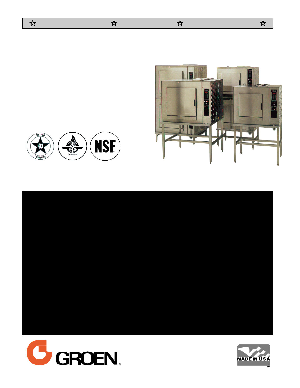
MODEL: CC10-GF, (2)CC10-GF
CC20-GF, (2)CC20-GF
CONVECTION COMBO™
Combination Steamer-
Oven
THIS MANUAL MUST BE RETAINED FOR FUTURE REFERENCE. READ, UNDERSTAND AND
FOLLOW THE INSTRUCTIONS AND WARNINGS CONTAINED IN THIS MANUAL.
FOR YOUR SAFETY
DO NOT STORE OR USE GASOLINE OR OTHER FLAMMABLE VAPORS
AND LIQUIDS IN THE VICINITY OF THIS OR ANY OTHER APPLIANCE.
POST IN A PROMINENT LOCATION
INSTRUCTIONS TO BE FOLLOWED IN THE EVENT USER SMELLS GAS.
THIS INFORMATION SHALL BE OBTAINED BY CONSULTING YOUR LOCAL
GAS SUPPLIER. AS A MINIMUM, TURN OFF THE GAS AND CALL YOUR
GAS COMPANY AND YOUR AUTHORIZED SERVICE AGENT. EVACUATE
ALL PERSONNEL FROM THE AREA.
WARNING: IMPROPER INSTALLATION, ADJUSTMENT, ALTERATION,
SERVICE OR MAINTENANCE CAN CAUSE PROPERTY DAMAGE, INJURY
OR DEATH. READ THE INSTALLATION, OPERATING AND MAINTENANCE
INSTRUCTIONS THOROUGHLY BEFORE INSTALLING OR SERVICING THIS
EQUIPMENT.
Information contained in this document is
known to be current and accurate at the time
of printing/creation. Unified Brands recommends referencing our product line websites,
unifiedbrands.net, for the most updated
product information and specifications.
Page 2

OM-CC-G
IMPORT ANT — READ FIRST — IMPORTANT
WARNING:
CAUTION: SHIPPING STRAPS ARE UNDER TENSION AND CAN SNAP BACK WHEN CUT.
CAUTION:
CAUTION:
WARNING: TO AVOID DAMAGE OR INJURY, FOLLOW THE WIRING DIAGRAM EXACTLY WHEN
CAUTION:
WARNING:
WARNING:
IMPORTANT:
IMPORTANT:
WARNING:
THE UNIT MUST BE INSTALLED BY PERSONNEL QUALIFIED TO WORK WITH ELECTRICITY
AND PLUMBING. IMPROPER INSTALLATION CAN CAUSE INJURY TO PERSONNEL AND/OR
DAMAGE TO THE EQU IPMENT. THE UNIT MUST BE INSTALLED IN ACCORDANC E WITH
APPLICABLE CODES.
DO NOT INSTALL THE UNIT IN ANY WAY WHICH WILL BLOCK THE RIGHT SIDE VENTS,
OR WITHIN 12 INCHES OF A HEAT SOURCE SUCH AS A BRAISING PAN, FRYER, CHAR
BROI LER OR KETTLE.
LEVEL THE UNIT FRO NT TO BA CK, OR PITCH IT SLIGH TLY TO THE REAR, TO A VOID
DRAINAGE PROBLEMS.
CONNECTING A UNIT.
DO NOT USE PLASTIC PIPE. DRAIN MUST BE RATED FOR BOILING WATER.
DO NOT CONNECT THE DRAIN DIRECTLY TO A BUILDING DRAIN.
BLOCKING THE DRAIN IS HAZARDOUS.
Improper drain connection will void warranty.
Do not al low any water traps in the li ne. A trap can cause pressure to build up insi de the
cavit y during steaming, which will make the door gasket leak.
WHEN YOU OPEN THE DOOR, STAY AWAY FROM STEAM COMING OU T OF THE UNIT.
STEAM CAN CAUSE BURNS.
WARNING: BEFORE CLEANING THE OUTSIDE OF THE STEAMER, DISCONNECT THE ELECTRIC POWER
SUPPLY. KEEP WATER AND CLEANIN G SOLUTION S OUT OF CONTROLS AND ELECTRICAL
COMPONEN TS. NEVER HOSE OR STEAM CLEAN ANY PART OF TH E UNIT.
WARNING:
WARNING:
WARNING:
WARNING: DO NOT PUT HANDS OR TOOLS INTO THE COOKING CHAMBER UNTIL THE FAN HAS
WARNING:
NOTICE:
NOTICE:
WARNING:
ALLOW COOKING CHAMBER TO COOL BEFORE CLEANING.
CAREFULLY READ THE WARNINGS AND FOLLOW THE DIRECTIONS ON THE LABEL OF EACH
CLEANING AGENT.
DELIMING AGENT MANUFACTURER.
DO NOT MIX DE-LIMING AGENTS (ACID) AND DE-GREASERS (ALKALI).
STOPPED TURNING.
DO NOT OPER ATE TH E UNIT UN LESS THE REMOVABLE RIGHT SIDE PANEL HAS BEEN
RETURNED TO ITS PROPER LOCATION.
DO NOT USE A CLEANING OR DE-LIMING AGENT THAT CONTAINS ANY SULFAMIC ACID
OR ANY CHLORIDE, INCLUDING HYDROCHLORIC ACID. IF THE CHLORIDE CONTENT OF
ANY PRODUCT IS UNCLEAR, CONSULT THE DISTRIBUTOR OR MANUFACTURER.
DO NOT USE ANY DE-GREASER THAT CONTAINS POTASSIUM HYDROXIDE OR SODIUM
HYDROXIDE OR THAT IS ALKALINE.
USE OF ANY REPLACEMENT PARTS OTHER THAN THOSE SUPPLIED BY GROEN OR THEIR
AUTHORIZED DISTRIBUTOR VOIDS ALL WARRANTIES AND CAN RESULT IN BODILY INJURY
TO THE OPERATOR AND DAMAGE THE EQUIPMENT. SERVICE BY OTHER THAN FACTORYAUTHORIZED PERSONNEL WILL VOID ALL WARRANTIES.
USE SAFETY GLASSES A ND RUBBER GLOVES AS RECOMMENDED BY
WARNING:
HIGH VOLTAGE EXISTS INSIDE CONTROL COMPARTMENTS. DISCONNECT FROM BRANCH
BEFORE SERVICING. FAILURE TO DO SO CAN RESULT IN SERIOUS INJURY OR DEATH.
2
Page 3

Table of Contents
OM-CC-G
IMPORTANT OPERATOR SAFETY WARNINGS
EQUIPMENT DESCRIPTION
INSPECTION AND UNPACKING .............................................5
WATER CONDITIONING/RE QUIREMENTS
INSTALLA T I ON
INITIAL START-UP.......................................................11
OPERATING INSTRUCTIONS
CLEANING
MAINTENANCE ........................................................26
TROUBLESHOOTING
DIAGRAMS AND SCHEMATICS
.........................................................
............................................................
....................................................
................................................
..............................................
.............................................
.................................
.....................................
2
4
6
7
13
19
26
28
REFERENCE...........................................................29
SERVICE LOG
WARRANTY PROTECTION ................................................31
..........................................................
30
3
Page 4
OM-CC-G
Equi p men t D escr i p ti o n
Your Groen Convection Combo™ has a stainless
steel cooking ch amber, an air heating com partment
with heat exchange tubes and fan, a steam
generator, and a control compartment which houses
elect rical components.
All m ajor compon ents of the Convection Combo™
are encased in a 16 gauge stainless st eel ca binet.
The cabinet is lined with 1½ to 2 inches (4 to 5 cm)
thick glass fiber insulat ion. A rem ovable drip tray is
located beneath the door.
Door hinges are reversible so that doors ma y open
from t he left or r ight. Opera tor controls are l ocated
on the right fr ont of the unit, except for the pilot
control switch and manual gas shut-off valve, which
are behind the slidi ng access door on the right side.
Standard cont rols l et you to opera te the Con vection
Combo in any one of t hree cooking modes:
1. As a convection oven
2. As a self-contained pressureless steamer
3. As a combination oven-steamer
Models CC10- G and CC20-G differ in cooking
chamber size and pan capacity:
CC10-G: 4 steam table pan s (12x20x2½”), or
7 half-siz e (13x18" ) U S bakin g pans
An insulated, gas-fired steam gen erator is mou nted
behind the oven. Steam enter s the oven th rough a
connecting tube near t he bottom left rear corner of
the oven.
On single CC10- G units which were supplied without
stands, de-limi ng solut ion is added to the unit through
the port located on top of the unit, direct ly above th e
steam gen erator. U nits supplied with stands have a
port on the st and ju st below the con trol panel. Delim ing solu tion goes through this port into a fill tank,
from which it i s transferred to the steam gen erator
during the unique Groen automati c cleaning cy cle.
The air heating space which contains the heat
exchanger tu bes is also separated from the cooking
chamber by r em ovable left , right, t op and bottom
partitions. The compartment which contains the unit’s
automatic controls and other electrical components is
on the right side of th e unit, and is accessed by
removing the right outside panel.
A drain is l ocated in the removable bott om of the
cooki ng chamber. Fluids drain from this removable
bott om and from t he permanent floor to the stainless
steel drain pipe outside t he oven. The drai n pipe
includes a spray condensor, which suppresses any
steam esca ping from the chamber. On Convection
Combo™ units manufactured after August 1, 1991,
the drain assembly also includes a drain box.
CC20-G: 10 steam table pan s (12x20x2½”), or
9 ful l-si ze (18x26") US baking pans
Alt hough some early m odel CC10-G units were
manufactured for counter-top installation, all units are
now supplied on a stainless st eel stan d. The smaller
Convection C om bo™ is available as the single C C10GF or the double stacked (2) CC10-G F. The larger
unit is avail able as the single C C 20-GF or the doublestacked (2)CC20-GF.
Controls and monitoring displays for cooking times,
operati ng mode and temperatur e selecti on are on the
control panel. The upper por tion of th e panel has a
digital cooking time rea dout an d touch pads for
setting cook times. Below the timer section are lights
which indicate the status of the unit and touch pads
to sel ect the mode of operation and to switch on
power.
A digi tal readout sh ows the sel ected temperatu re,
which is entered by turn ing a dial. Pil ot burn er status
is shown by a light on the pilot ignition switch.
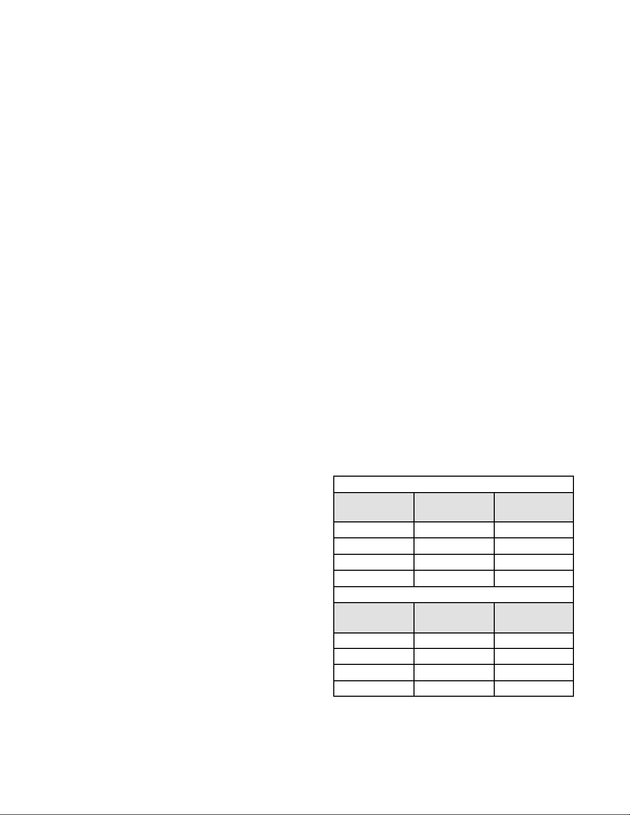
BURNER FIRING RATES
Input Rates, BTU/hour
CC10-G or per chamber for (2) CC 10-G
Mode
Oven 45,000 45,000
Steam 48,000 48,000
Combo 54,600 54,600
Preheat (Max) 93,000 93,000
CC20-G or per chamber for (2) CC 20-G
Mode
Oven 90,000 90,000
Steam 100,000 100,000
Combo 100,000 100,000
Preheat (Max) 186,000 186, 000
*Manifold Pressure
Natural Gas
at 3. 7" W .C.*
Natural Gas
at 4. 5" W .C.*
L.P. G as
at 10. 5" W .C.*
L.P. G as
at 10. 0" W .C.*
4
Page 5
Insp ecti o n an d U n p acki n g
OM-CC-G
Your Convection Combo™ will be completely
assembled in a heavy shipping carton (CC10-G) or
wooden crat e (CC20- G), an d atta ched to a sk id. On
recei pt, inspect the ca rton or crate carefully for
exteri or dam age.
CAUTION
SHIPPING STRAPS ARE UNDER T ENSION AND
CAN SNAP BACK WHEN CUT.
Carefully cut the straps around the carton and detach
the sides of the carton from the skid. Pull the carton
up off the unit. Be careful to avoid personal injury or
equipment damage from nails and sharp pieces of
wood or staples which might be left in cart on walls.
Write down the model number, serial number and
installation date and keep this information for future
reference. Space for these entries is p ro vided at the
top of the Service Log in the back of th is manual.
CAUTION
THIS UNIT IS VERY HEAVY. YOU SHO UL D GET
HELP AS NEEDED AND USE MATERIAL
HANDL ING EQ UIP M ENT TO RE M O VE T HE UNIT
FROM THE SKID AND M O V E IT T O ITS PLACE
OF INSTALLA TION .
When starting installation, use material handling
equipment to lift the unit straight up off the skid.
Check packi ng materials t o m ake sur e loose parts
are not discarded with th e m aterial.
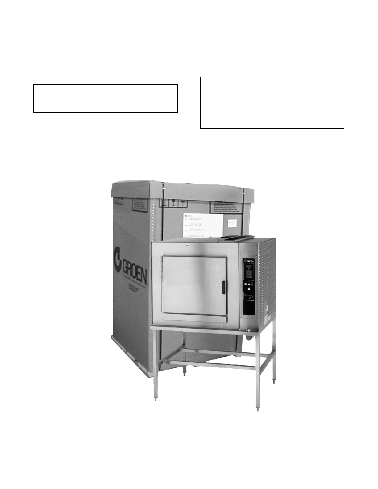
The unit will be delivered in either a heavy carton ( CC 10-G
and CC20-G) or a heavy wooden crate ((2) CC 10-G and (2)
CC10-G), strapped to a wooden ski d. (CC20-GF pictured)
5
Page 6
OM-CC-G
Water Conditioning
It is essential to supply the steam generator with
water that will n ot form scale. Even though the
steam gen erator is engineered to minimize scale
formati on, scale development depends on th e
hardness of your water and the number of hours you
operate t he equipment.
In some areas, water is low enough in mi neral
content to avoid scale formation. But most water
supplies are full of minerals which form scale. It is
this scale which could lead to an early component
failure.
Your water utility can tell you about the minerals in
your water . The water going to the steam gen erator
should have between 30 and 40 parts per million
(ppm) total dissol ved solids (TDS) and should have a
pH (acidity rating) of 7. 0 to 9.0. Please follow these
simple precautions:
1. Do not rel y on unproven water treat m ents
which a re sold for scale prevention or scale
removal. They don’t alw ays w ork. The best
way to pr event sca le is t o supply the purest
possible water (30- 40 ppm TD S).
2. If your water contains scale-forming minerals, as
most water does, use a well -ma intain ed water
soften er. Wh ether an exchangeable softener
cartridge or a regener ating system is ch osen, a
regular exchange schedule is essential.
3. Installing a water meter between the softener
and the steamer will provide an accurate gauge
of water use, and will help determine when to
exchange cart ridges or regenerate the soft ener.
Using a water softener will provide longer
generator life, higher steam capacity, and reduce
maintenance requirements.
4. If you notice a slow down in steam production ,
have th e unit checked for sca le build-up. H eavy
scale reduces the unit’s ability to boil water.
MINIMIZE SCALE PROBLEMS, BY USING AND
MAINTAINING A SOFTENER, AND BY CLEANIN G
THE STEAM GENERATOR REGULARLY.
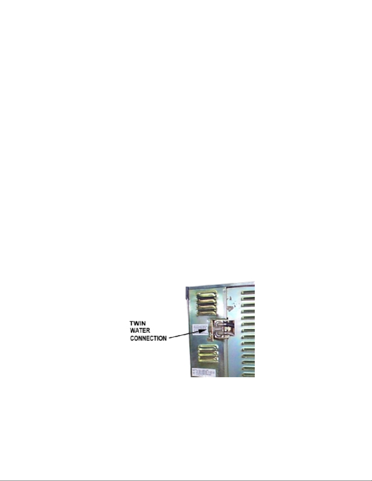
Groen Convect ion C om bo™ ovens are also available
with an option for two separate water connections —
one for the stea m generat or (soft water ), the other
for the spray condenser (untreated water). The
steam gen erator only uses 14 to 31% of a
combination oven’s water.
Since softener systems are typically sized by total
GPH (gallons per hour), the second connection could
reduce tr eatment requir em ents by u p to 80%,
resulting in significant savings.
Optional separate w ater connecti ons for
steam generat or and drain spray condenser.
6
Page 7

OM-CC-G
Installation and Start-Up
WARNING
THE UNIT MUST BE INSTALLED BY PERSONNEL WHO ARE QUALIFIED TO WORK WITH ELECTRICITY AND
P L UM B ING . IM P ROP E R INSTALL AT I ON C AN CAUS E INJURY T O PE RS ONNE L AND /O R DAMAG E T O T H E
EQUIPMENT. THE UNIT MUST BE INSTALLED IN ACCORDANCE WITH APPLICABLE CODES.
CAUTION
DO NOT INSTALL THE UNIT WITH THE RIGHT SIDE VENTS BLOCKED OR WITHIN 12 INCHES OF A HEAT
SOURCE (SUCH AS A BRAISING PAN, DEEP FRYER, CHAR BRO IL ER O R K ET TLE ). D O NOT I NST AL L T O
THE LEFT OF ANY O PEN-FLAME EQUI PMEN T.
TO AVOID DRAINAGE PROBLEMS, LEVEL THE UNIT FRONT TO BACK.
Installation
Mounting
1.
If you wish t o install a Convection Combo™ on
top of a nother , you shoul d obtain a double
stacked unit from the factory.
The unit m ust be installed i n an adequately
vented room w ith a provision for an ample air
supply to the unit. The unit must be installed
completely under a v entilation hood, since fl ue
products exit the applia nce over its entire depth.
Anything which m ight restri ct the flow of air for
ventilati on and combustion m ust be removed. Do
not obstruct the flue cover or any front, side, top
or rear vents after installation. The area directly
around the Convection Combo™ m ust be cleared
of al l combu stibl e m aterial.
Inst alla tion mu st comply with local codes, or in
the absence of local codes, conform to the
National Fuel G as Code ANSI Z223.1 - latest
edit ion, including:
“The appliance and its individual shut-off valve
must be disconnected from the gas supply
pipi ng system duri ng any pressure testing of that
system a t test pressures in excess of ½ psig
(3. 45 kPa). The appliance must be isolated
from t he gas supply by closi ng its individual
manual shut-off valve during any pressure testing
of th e gas supply piping system at t est pressur es
equal t o or less than ½ PSI (3.45 kPa).”
2. Gas Supply Connections
WARNING
THIS UNIT IS FOR COMMERCIAL USE. NEVER
USE HOME OR RESIDENTIAL GRADE GAS
CONNECTIONS. THEY DO NOT MEET GAS
CODES AND COULD BE HAZARDOUS.
Connect to the gas suppl y usin g ¾ NPT pipe or
an a pproved equiva lent. Al though the immediate
connection to the Convection Combo™ is ¾
NPT, the ga s supply piping m ust be large enough
to pr ovide 93,000 BTU /hour for each CC10
cooki ng chamber or 186,000 BTU /hour for each
CC20 cooking chamber. Supply pressure must
be at least 5" W.C. (maximum 14" W.C.) for
natural gas or 12" W.C. (maximum 14" W.C.) for
LP gas. In Canada, the installation must
conform to the Canadian Gas Code, CAN 1B149, Install ation C odes for Gas B urni ng
Appli ances and Equ ipmen t, and/or loca l codes.
For units on casters, complete the gas supply
connection using only connectors that meet the
standards for mov able gas a ppliances, ANSI
Z21.69 — latest editi on. Restrain movemen t of
the unit by attaching a cable or chain to the
eyel et (provided at the back of the frame) and
anch oring the cable or chain to the w all or fl oor.
Make the length and location of the cable such
that the unit cannot pull on the gas connection
while the ca ble is connected.
Elect rical Supply C onnection
3.
For a single oven, or for each oven in a double
stacked unit, provide 115 VAC, 60 H z, one
phase, 15 A MP servi ce. Local codes and/or the
National Electrical Code should be observed in
accordance wit h ANSI/NFPA 70-1987 (or latest
edit ion). AN ELECTRICAL GROUND IS
REQUIRED. The elect rical schemati c is located
in the service compartment and this manual.
Maximum load per oven is 5½ AMPs. In
Canada provide el ectrical service i n accorda nce
with the Canadian Electrical Code, CSA C22.1
Part 1, and/or local codes.
7
Page 8

OM-CC-G
W ater Supply Connect ion
4.
A check val ve (an ti-siphonage device) m ust be
installed in the incoming cold water line in
keeping with local plumbing codes. Water line
pressure should be between 30 and 60 PSI (210
and 410 kPa) . A pressure regu lator is requir ed
above 60 PSI (410 kPa ).
A ¾ inch (19 mm) N H connector i s required to
connect the water supply to the water inlet valve.
The water feed line diameter ma y not be less
that ½ inch (13 mm). Use a washer (or if
necessary, two washers) in th e hose connection.
Do not allow the connection to have any leak, no
matter how small.
If you have a CC10-G which is equipped wit h the
opti onal split water supply, the stea m generat or
supply must be able to fill the generator with 3
gallons (11. 4 lit ers) of wa ter i n 5 minutes. The
make-up water rate is 0. 06 gallons per minute
(0.2 liters per minute). Condensate spray water
rate i s 0.34 gallons per minute (1.3 lit ers per
minute) at 30 PSI (210 kPa). These
requir em ents apply to each steam generat or in
model (2)CC10-G.
If you have a CC20-G which is equipped wit h the
opti onal split water supply, the stea m generat or
water supply must be able to fill the generator
with 5 gallons (19 lit ers) of water in 5 m inutes.
The make-u p water rate is 0.12 gallons per
minute (0.45 li ters per minute) . Condensate
spray water rate is 0. 7 gallons per minu te (2.6
liters per minute) at 30 PSI (210 k Pa). Th ese
requir em ents apply to each steam generat or in
model (2)CC20-G.
4. Drain Connect ion
Unit Without Drai n Tank
a.
A 1½ inch (4 cm) ID (CC10-G) or 2 inch (5
cm) ID hose (CC 20-G) may be attach ed to
the supplied dr ain outl et with a cla m p. Do
not use plasti c pipe, because the drain m ust
withstand very hot water.
other el bows or other r estricti ons between
the unit drain and the free air gap.
CAUTION
DO NO T USE PLASTIC PIPE. DRAIN MUST B E
RATED FOR VERY HOT WATER.
WARNING
BLOCKING THE DRAIN IS HAZARDOUS.
On a double stacked unit, t here must be a
minimum of two i nches free a ir gap on each
drain, as close to each oven as possibl e.
Double stacked units may only share a
common drain hose downstream of both
free a ir gaps.
Install the drain line with a constant
downward pit ch.
IMPORTANT: Do not allow any water traps in the
li ne. A trap can cause pressure to bui ld up
insi de the cavity during steam ing, which will
make the door gasket leak.
NOTE: Improper drain connection will void the
warranty.
b. Units With Drain Tank
A hose m ay be at tached t o the supplied
drain elbow w ith a cla m p. Use 1½ inch ID
hose for C C10-G or 2" ID hose for C C 20-G.
The hose may be connected directl y to a
building drain since the drain tank has an air
vent, which eliminates the need for a fr ee air
gap at the building drain.
Do not block the air vent in any wa y . Do not
attach anythin g to the vent tube or reduce its
size.
Do NO T use plastic pipe i n the drain line,
because the drain must withstand very hot
water.
WARNING:
DO NOT CONNECT THE OVEN DRAIN DIRECTLY
TO A BUILDING DRAIN.
There mu st be a free air gap between the
end of t he hose and the buildi ng drain. The
free a ir gap shoul d be as close as possible
to the unit’s drain. There must also be no
8
Page 9
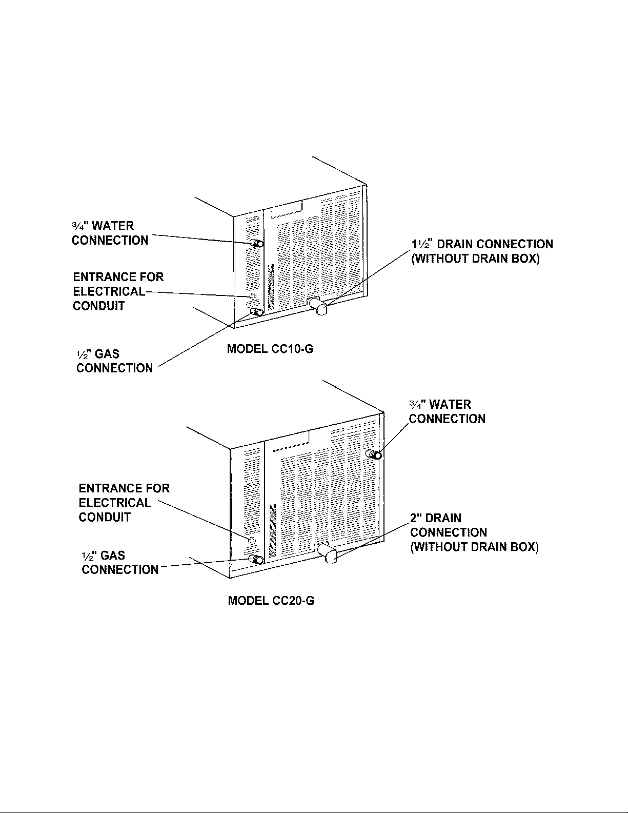
Con vecti o n C o mb o ™ Utility Connections
NO TE: Rem ove ri ght side panel to make connections
at t erminal block in rear of control compartment.
OM-CC-G
9
Page 10
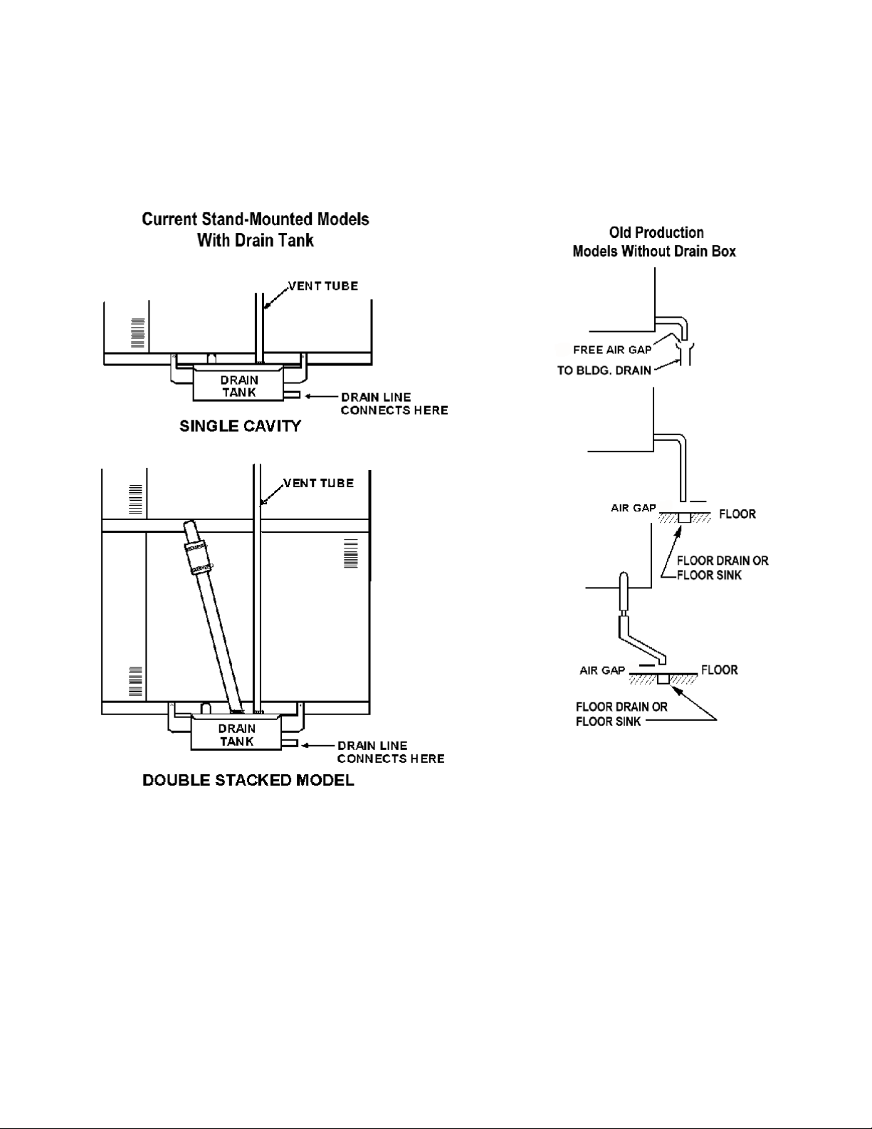
OM-CC-G
Proper Drain Line Connections
10
Page 11

OM-CC-G
Initial Start-Up
WARNING
ANY P OTENTIAL USE R OF T HE E QUIP M E NT SHO UL D B E TRAIN E D IN S AFE AND CO RREC T O PE RAT ING
PROCEDURES.
After the Convection Combo™ has been installed,
test it to ensure th at it is operati ng correctly.
Remove all literature and packing materials from
1.
the interior and exterior of the unit.
2. Check tha t the cold wa ter supply line is open and
that the fittings are not leaking.
Make sure that the gas suppl y line is open. On
3.
newer units, turn the knob of the main gas valve
so that it is lined up with the pipe. On older units
turn the ma in gas val ve knob to the “On” posi tion.
(See illustration at the bottom of this page)
Turn on electri cal
4.
service to the unit.
Because the unit wi ll
not operate w ithout
elect rical power, no
att em pt should be
made to operate the
unit in the event of a
power failure.
The control panel
5.
will not operate until the
pilot burn er has been
ignited. To light the pilot burner, activate the pilot
switch located next to the main gas valve. Once the
pil ot ignition sequence has been successfully
completed, a green light will glow, an d power will be
supplied t o the front panel.
6. The “t rial for igniti on” period is r oughly 90
seconds. If the pilot burner does not light w ithin
90 seconds of pilot switch activation, the ignition
system a utomat ically stops the gas flow to th e
pilot burner and cancels the ignition trial. If the
ignition trial is terminated, turn off the pilot switch
and repeat the trial for ignition. During initi al
start-up, the pilot may require several trials in
order to bleed air from t he gas piping.
Subsequent start-up should only require about
five seconds to achieve ignition.
NOTE:
7. Once the pilot burner flame has been esta blished
See Automa tic Opera tion of Pilo t at the end
of this section.
(the green light at the pilot switch is on), all
operator comma nds are executed via the fr ont
control panel touch pads. See the Operation
section for details.
High Altitude Operat ion. At altitudes above
8.
5,000 feet (1524m), the uni t will n ot oper ate in
the Steamer or Combo Modes unless the altitude
is set. You can program the altitude as follows:
a. If the unit is on, turn it off by pressing the ON
touch pad.
b. Press and hold the STEAM touch pad while
turning the unit on by pressing the ON touch
pad. The Timer Display will show the letters
AL and a number representing the altit ude in
thousands of feet. If the altitude has not
been set for y our unit , the display w ill be 0.
c. Enter an altitude value between 0 and 15,
usi ng the numbered touch pads. For
example, if the unit w ill be opera ting at 7,000
feet, enter 7.
d.
9.
Press the START touch pad.
Alti tude Metric Conversion
Altitude
Feet Meters
5000 1524 5
6000 1830 6
7000 2133 7
8000 2438 8
9000 2745 9
10000 3048 10
11000 3353 11
12000 3658 12
13000 3962 13
14000 4267 14
15000 4572 15
Select Fahrenheit or Cel sius Temperatures.
The Convection Combo™ is deli vered wi th the
Fahrenheit scale as default. To change the
temperature scale, hold the 5 key in , and press
ON. The Timer Display will show dEG°F or
dEG°C. P ress the 5 key to change fr om one to
the other. Press STAR T to accept the change.
Setting
11
Page 12

OM-CC-G
To Test St eam er Mode Operation, turn on the
10.
unit. ( For operating procedu re detail s, see the
Operation section of this manual.) Clear time
from t he time display. Close the door an d press
the ST EAM touch pad. (If the HOT light is on,
see Fast Cool i n the Operation secti on.)
The WAIT light will stay on while the steam
generator fills with and heats the water. It
should turn off within three minutes, and the
READY light should come on. This indicates that
the water is at its standby temperature. The
ti m er only controls operations in the Steamer
Mode. Enter a time a nd press START. (“Time”
is set in minutes and hours only. Seconds are
not displ ayed).
Examples: 2 minutes = 00:02
(Just pr ess 2).
1 hour an d 30 m inutes = 01:30
(Press 1, 3, and 0, or press 9,0 the
timer will change to 1: 30)
The colon [:] between the numbers will blink an d
the generator will begin to pr oduce steam. Time
only coun ts down when the READY light is lit.
NOTE: You cannot change modes if the ti m er is
running.
nd clear any time from the timer display. Press the
COMBO touch pad. Set the COOK temperature t o
o
F (175oC). The WAIT light will come on. It will
350
remain on while (1) the steam generator fills with
water and heats it to its standby temperature and (2)
the air heater raises the air t em peratu re to 350
o
F.
Both actions should be complet ed in fi ve to eight
minutes, starting with a cold unit. When the set
temperature is att ained, the WAIT light will go off,
and the READY light will come on. NOTE: The timer
does not control the oven in eit her the C om bo or
Oven Modes.
To Test Oven Mode Operation, turn on the
10.
power and clear the timer display. Press the
OVEN touch pad. Set the cook temperature to
o
F (175oC). The WAIT light will come on.
350
Within eight minutes of a cold start, the WAIT
lig ht shou ld go out and the READY light come on.
When that happens, turn the COOK setting down
o
to 320
F (160oC). The HOT light will come on.
Heat-up times may vary slightly with voltage or
water pressure differences.
To shut down the unit, first clear the timer. Next,
11.
press t he mode pad for t he mode in which the
unit is oper ating. Finally, switch off t he power.
The pilot burner m ay al so be turned off to
conserve energy.
WARNING
WHEN YOU OPEN THE DOOR, STAY AWAY
FROM STEAM COMING OUT OF THE UNIT.
THE STEAM CAN CAUSE BURNS.
To Test Combo Mode Operation, turn on the
8.
p
o
w
e
r
a
If the C onvection Combo™ works as described,
12.
the unit is functioning correctly and is ready for
use.
These controls are behind t he sliding door on the right side panel , facing the uni t.
12
Page 13

OM-CC-G
Operation
WARNING
ANY P OTENTIAL USE R OF T HE E QUIP M E NT SHO UL D B E T RAI NED IN S AFE AND CO RREC T O PE RAT ING
PROCEDURES.
DO NOT OPERATE THE UNIT AT ALL, UNLESS ALL FOUR REMOVABLE PARTITIONS HAVE BEEN
RETURNED TO THEIR PROPER LOCATION.
DO NOT OPERATE THIS EQU IPMENT WITHOUT ELECTRIC POWER.
NOTE: Before t he contro l panel can be used, the pilot burner fla m e m ust be on. See “Init ial Start-Up.”
Control s and Indicat ors
A.
Operator controls are on the right fr ont side of the
unit. Their use is described bel ow:
Time Section
1.
In Oven and Combo M odes, the timer functions
only as a “cooking ti m e m inute min der” and does
not turn the unit on or off. In the Steamer Mode,
however, it controls the steaming function.
Displ ay Window — Show s operating time
a.
remaining in the Steamer , Ov en or Combo
Mode. Th e timer counts down. The
window shows operating time in
“hours: m inutes” format. For example,
entering 9 and 0 will result in a display of
01:30. (On som e older units numbers higher
than 59 will not be accepted - in these
cases, convert the time to hours and
minutes. 90 minutes is entered 1,3, 0.
b. Time t ouch pads — used to enter time
values.
CLEAR — Pressing this touch pad once
c.
stops t he beeper and reset s the timer to the
time that was last set. Pressing twice clears
it to 00:00. A t the end of a cooking period,
opening the door is t he same as pressing
CLEAR once.
START — Press this touch pad to start the
d.
ti m er. If the unit is in Steam er M ode, it will
also cause steami ng to begin.
Stat us Lights
2.
a. HOT — Indicates cham ber tem perature is
more than 15
temperature. (See Paragra ph 5 in this
section)
o
F (8oC) over the set
sound and the SERVICE light will be on wh en
you sw itch on the power. The unit ma y
continue to operate, depending on the type
of problem . Refer t o the Troublesh ooting
secti on to determin e the natu re of the
problem.
c. WAIT — Indicates the unit is either heating
or cool ing tow ard the set temperatu re. The
HOT and WAIT lights will both be on if the
chamber is more than 15
set poi nt.
d. READY — Indicates the unit is ready for use.
3. Cooking Mode Select ion
These touch pads ar e used to select the mode of
operati on. If a mode is off, pressing the pad for
that mode w ill tu rn it on. If the mode is on,
pressing its pad will turn it off. A light just above
each pad show w hich h as been selected.
o
F (8oC) above the
SERVICE — Indicates that there is a
b.
probl em which might require a service call.
If there is such a problem t he beeper wi ll
13
Page 14

OM-CC-G
Operation
Standard Operating Controls
14
Page 15

STEAM — Selects steamer operation only .
a.
b. COMBO — Selects superheated st eam an d
convection oven operation.
c. OVEN — Sel ects con vection oven opera tion
only.
Power
4.
The ON touch pa d turns the unit on or off. When
power is on, t he ON light ju st above the touch
pad is lit. Use of this pad does n ot reset the
controls. The unit will a lways come on in the
same m ode it wa s in when shut down.
5. Temperature (TEMP) Section
OM-CC-G
SERVICE light comes on when you turn on
the power, see the Troubleshooting section).
b. If the power is already on, and th ere is a
number in the time display window, press the
CLEAR touch pad one or more ti m es to
reset the time to zero.
NOTE: You cannot change operating modes
while the timer is running
c. The unit w ill be in the mode of operat ion in
which it was last used. Because of this, the
indicator light for that mode w ill be lit. If the
unit is not alr eady in the Stea mer Mode,
press t he STEAM tou ch pad. Th e STEAM
light will come on and the Temperature
Window will go blank.
If the unit was recently used in Ov en or
d.
Combo Mode, t he HOT light may come on,
indicati ng tha t the cook ing chamber i s too hot
for use as a steamer. The unit can be
cooled quick ly to the steami ng tempera ture
range by leaving the door open or foll owing
the Fast Cool procedure described near the
end of this section (Paragraph 5). With the
door open, t he generator can fill and heat the
water to 200
steam.
o
F (93oC), but it cannot produce
The Temperatu re Display Window shows the
a.
select ed temperatur e in either Oven or
Combo Mode. It is blank in the Steamer
Mode.
b. Turning the Temperatu re Con trol K nob
select s the cooking te m peratures in 5
increments. The control ranges are:
Oven Mode 200-575
Combo Mode 220-575
Operati ng Instruct ions
B.
Steamer Mode
1.
o
F (95- 300oC)
o
F (105- 300oC)
a. If the unit is off, swit ch on th e electric power
by pressing the ON touch pad. (If the
o
F
WARNING
WHEN YOU OPEN THE DOOR STAY AWAY
FROM ANY STE AM COMI NG OUT O F THE UN IT.
STEAM CAN CAUSE BURNS.
The WAIT light will be on until the water
e.
reaches 200
o
F (93oC). It will then turn off
and the READY light will come on. You are
now ready to st eam foods in y o ur Convecti on
Combo™.
Load the food i nto pan s in an even, uniform
f.
layer.
g. Carefully open the door and slide the pan or
pans on to the pan r acks in the cooking
chamber. If you are only using on e pan,
place it in the m iddle posi tion. Close the
door.
15
Page 16

OM-CC-G
Press the numbered t ouch pads to set t he
h.
cooking time. The time will appear in the
Time Display Window. If you enter the
wrong number, press t he CLEAR touch pad
to erase the time from the display, a n d enter
the time again.
i. When the correct cooking ti m e has been
entered, press the START pad. The colon in
the display will blink and the time will count
down the cook ing time. (The u nit must be
READY before the timer can count down.
SERVICE light comes on when you turn on
the power, see the Troubleshooting section).
If the door is cl osed and the cooking
temperature is above 200
o
F (93oC) the fan
will begin to opera te.
b. If the power is already on, and th ere is a
number in the time display, press CLEAR
one or more times to reset the time to zero.
NOTE: You cannot change operating modes
while the timer is running
If you open the door durin g the cooking
j.
period, steaming and the timer will stop (but
will not reset). When you close the door,
steaming and timing will continue.
WARNING
WHEN YOU OPEN THE DOOR STAY AWAY
FROM ANY STE AM COMI NG OUT OF THE UNIT.
STEAM CAN CAUSE BURNS.
k. When the timer reaches zero, it stops steam
generation and sounds a beeper. Water in
the steam gen erator stays at i ts standby
temperature (200
o
F - 93oC). On older
models, the beeper will sound until the door
is open ed or CL EAR is pressed.
l. Ca refully open the door. If the food is
cooked, remove the pans using hot pads or
oven mitts to protect your hands.
m. After the display has counted down to zer o
opening the door or pressing CLEAR once
will reset the display to the time that was last
used. Pressing START will repeat the cook
cycle. If the same cooking time will be used,
you only need to press the number keys
when you first set that time.
c. The unit w ill power up in the mode in w hich it
was last used. Because of this, the indicator
light for that mode will be lit. If the unit is not
already in the O ven Mode, press the OVEN
touch pad. The OVEN light will come on an d
the oven fan will operate.
d. Use the Tem perature Contr ol Knob to set the
desir ed cooking tem perature, which will
appear in the temperatur e display. U nless
the cooking chamber i s already at or above
the selected temperature, the unit will start
heating and the WAIT light w ill come on.
If the unit was recently used at a
e.
temperature 15
o
F (8oC) or more over the
select ed temperatur e, the HOT and WAIT
lights will come on. The unit can be cooled
quickl y to the desired cooking tem perature
by l eavin g the door open or foll owing t he
Fast Cool procedure descri bed near t he end
of this section (Paragraph 5).
f. The READY light will indicate when the oven
is a t the desired temperature.
g. Load the food i nto the pan or pans i n a
uniform layer.
n. After the display has counted down to zero
you can reset the time to zero by either (1)
opening the door and pressing CLEAR or
pressing CLEAR twice. A new cooking ti m e
may then be set by using the number keys.
Oven Mode
2.
a. To use the Convection Combo™ as a
convection oven, sw itch on th e electric power
by pushing the ON touch pad. (If the
16
Page 17

The Convection Combo™ will operate in
h.
Oven Mode with the timer either on or off. If
you want to time cooking, press the
number ed pads in the TIM E portion of t he
control panel to set the cooking time. The
time will appear in the Time Display . If you
enter t he wrong number, pr ess CLEAR to
erase the ti m e from the display, and reenter
the time. Remember that the timer does not
control the unit in th e Oven Mode.
i. Open the door a nd slide the pan or pans
onto the pan racks in the cooking chamber.
If you are only usin g one pan, place it i n the
middl e position. Close the door.
If the correct ti m e has been set on the
j.
timer, press the START pad. The colon [:]
between the numbers in the display will blink
and the time will count down th e cooking
time. When the timer has counted down to
zero, it will sound a beeper. This soun d will
continue until the door i s opened or th e
CLEAR pad is pressed.
To stop cooking, t ake th e pans out of the
k.
oven using hot pads or oven mit ts to pr otect
your hands from the hot pans. The unit will
continue heating to keep the chamber at the
set temperature until the temperature control
is reset, or the power is shut off.
OM-CC-G
o
temperature is above 200
will begin to opera te.
b. If the power is already on, and th ere is a
number in the time display window, press the
CLEAR touch pad one or more ti m es to
reset the time to zero.
NOTE: You cannot change operating modes
while the timer is running
c. The unit w ill power up in the mode of
operati on in which it was last used. Becau se
of th is, t he indicator light for t hat mode will
be lit. If the unit is not already in the Combo
Mode, press the COMBO touch pad. The
COMBO light will come on and if the steam
generator is not already full, water will flow
into i t and begin h eating.
Use the Tem perature Contr ol Knob to set the
d.
desir ed oven temper atur e between 220 and
o
F (105 t o 300oC). The temperature wil l
575
appear in the temperatur e display window.
e. If the unit was recently used at a
temperature more than 15
than the temperature selected, the HOT and
WAIT lights will turn on. The unit can be
cooled quick ly by leav ing the door open or
following t he Fast Cool procedure described
near the end of this section (Paragr aph 5).
F (93oC) the fan
o
F (-8oC) higher
WARNING
PANS AND INTERNAL PARTS OF THE OVEN
WILL BE VERY HOT. AVOID CONTACT WITH
HOT SURFACES.
l. Open in g the door during operation shuts off
power to the heaters and fan and stops the
timer, but it has no other effect on the
control s. When the door i s closed, operation
continu es. Note that cooking time will be
extended by the period the door was open.
Combo Mode
3.
a. If the unit is off, swit ch on th e electric power
by pressing the ON touch pad. ( If t he
SERVICE light comes on when you turn on
the power, see the Troubleshooting section).
If the door is cl osed and the cooking
WARNING
WHEN YOU OPEN THE DOOR STAY AWAY
FROM ANY STE AM C OMING O UT OF THE UNIT.
STEAM CAN CAUSE BURNS.
f. The WAIT light will be on until the wa ter in
the steam generator reaches boiling and the
air i n the cook in g chamber r e aches th e set
temperature. It will then turn off and the
READY light will come on to indicate that the
oven is at the desired t em perature.
g. The unit will oper ate in C om bo Mode wit h the
timer either on or off. If you want to time the
cooking, press t he numbered pads in the
TIME portion of the control panel to set the
cooking time. The time will appear in the
Time Display Window. If you enter the
wrong number, press t he CLEAR touch pad
17
Page 18

OM-CC-G
to erase the time from the display, a n d enter
the time again. The timer does not cont rol
the unit in Combo Mode.
h. Load the food i nto the pan or pans i n a
uniform layer.
WARNING
WHEN YOU OPEN THE DOOR STAY AWAY
FROM ANY STE AM COM ING OUT OF THE UNIT .
STEAM CAN CAUSE BURNS.
Open the door and sl ide the pan or pan s
i.
onto the pan racks in the cooking chamber.
If you are only usin g one pan, place it i n the
middl e position. Close the door.
Fast Cool
4.
a. When the HOT indicator is lit and the timer is
cleared, the unit can be cooled qu ickly by
opening the door and pressin g START. The
fan will operate, and the TIME window wil l
display the word “COOL.” This is the only
ti m e the fan operates with the door open.
WARNING
DO NOT PUT HANDS OR OTHER OBJECTS
INTO THE COOKING CHAMBER DURING THE
FAS T C OO L OP ERATI ON. T HE RO T AT I NG F AN
CAN BE HAZARDOUS.
To stop t he Fast Cool operation, press any
b.
touch pad or close the door.
Shutt ing Down
6.
a. Press the touch pad for the mode in which
the unit is oper ating.
If the timer has been set, press the START
j.
pad. The colon [:] between the numbers in
the display will blink and the time will count
down the cook ing time. When the ti m er has
counted down to zero, it will sound a beeper.
This beepin g will continue until the door i s
opened or the CLEAR pad is pressed.
k. To stop cooking, ta ke the pa ns out of the
oven using hot pads or oven mit ts to pr otect
your hands from the hot pans. The unit will
continue steaming and heating the oven at
the set t em perature u ntil the temperature
control is reset, or the power is shut off.
b. Switch off the power by pressing the ON
touch pad.
Leave the door at least partially open, if local
sanitation regulations permit.
18
Page 19

OM-CC-G
Cleaning
To keep your Convect ion C om bo™ in proper operating condition and to make th e cleaning process easier, cleaning
should be a da ily activit y.
A. Suggested Tools and Cleaners
1. Mild det ergent
2. Stainless steel exterior cleaner such as
Zepper®
Steam gen erator de-li m in g agent, such
3.
as Groen Del imer Descaler, (P/N
114800) Li m e-A-Wa y® or an equivalent.
A liquid de-liming agent will be easier to use
than crystals or powders. See the warning
about chl orides below.
De-greaser, such as Encompa sS ® ,
4.
Groen Degreaser, Malone 34®, Puritan
Puribrute®, or Con -Lie®
Clot h or sponge
5.
Plasti c wool or a brush wit h soft bristles
6.
7. Spray bottl e
8. Measuring cup
9. Nylon pa d
Towels
10.
Plasti c disposable gloves
11.
Procedure
B.
Exterior Cleaning
1.
Prepare a w arm solu tion of the mild
a.
deter gent as instru cted by the supplier.
Wet a cloth with th is solution and wring it out.
Use the m oist cl oth to clean the outside of
the unit. Do not allow freely running liquid to
touch the controls, the control panel, any
elect rical part, or any open louver.
To remove material which may be stuck to
b.
the unit, use plasti c wool, a fi ber brush, or a
plasti c or rubber scraper w ith a detergent
solution.
c. Stainless steel surfaces may be polished
with a recognized stain less steel cleaner
such as Zepper®.
Singl e C C10-G Unit s
C.
NOTE: For instructions about cleaning the interior of
double-st acked CC10-G units or any CC20-G units,
go dir ectly to Section D, below.
PRECAUTIONS
WARNING
DISCONNECT THE POWER SUPPLY
BEFORE CLEANING THE OUTSIDE OF
THE UNIT.
KEEP WATER AND CLEANING
SOLUTIONS OUT OF CONTROLS AND
ELECTRICAL COMPONENTS. NEVER
HOSE OR ST E AM CLEAN ANY PART OF
THE UNIT.
BE CAREFUL CLEANING THE T OP FLUE
COVER AND THE OVEN TOP. BOTH
AREAS MAY BE VERY HOT.
DON’T MIX DE-LIMING AGENTS (ACID)
WITH DE-GREASERS (ALKALI)
ANYWHERE IN THE U NIT
AVOID CONTACT WITH ANY CLE ANERS,
DE-LIMING AGENT OR DE-GREASER AS
RECOMMENDED BY THE SUPPLIER.
MANY ARE HARMFUL. READ THE
WARNINGS AND FOLLOW THE
DIRECTIONS!
EVEN WHEN THE UNIT HAS BEEN SHUT
OFF, D ON’T PUT HAND S OR TOOLS I NTO
THE CO O K I NG CHAMBER UNTIL THE FAN
HAS STOPPED TURNING.
DON’T USE ANY CLEANING OR DELIMING AGENT THAT CONTAINS ANY
SULFAMIC AGENT OR ANY CHLORIDE,
INCLUDING HYDROCHLORIC ACID (HCl).
TO CHECK FOR CHLORIDE CONTENT
SEE ANY MATERIAL SAFETY DATA
SHEETS PROVIDED BY THE CLEANING
AGENT MANUFACTURER.
UNIT M AY B E HO T . TAKE P REC AUT IO NS
TO PREVENT CONTACT WITH HOT
SURFACES.
To clean the cooking ch amber and/or de-l ime the steam
generator of t he CC10-G, a special sequence of
operati ons (the C lean Cycle) has been pr ogra mm ed into
the Convection C om bo™ com puter. To run this
automat ic Clean C ycle for cleaning, de-l iming or both
actions at the same time, follow the instructions outlined
in the following table.
19
Page 20

OM-CC-G
This ta ble refer s to the paragraphs which fol low it.
Clean Cooking
Chamber Only
Omit steps 2 & 4 Omit st eps 1 & 3
Before beginnin g this procedure, cool t he over to
200ºF (90º C ) or lower. Close the door, put th e unit in
the Oven Mode, and select 200ºF. If th e HOT ligh t is
on, use the Fast Cool M ode to cool the oven unti l the
HO T light goes off. If the HOT li ght does not com e
on, open the door imm ediately to shut off th e
burners. Once the HOT light is off, you m ay proceed
safely.
UNIT MAY BE HOT. DO NOT TOUCH HOT
SURFACES.
DO NOT PUT HANDS OR OTHER OBJECTS
INTO COOKING CHAMBER WHILE CONVECTION
CO MBO ™ IS OPE RATI NG . THE ROTATING FAN
CAN BE HAZARDOUS.
a. Step 1 - Cooking Chamber
Cool/ reduce th e oven to the desired
temperature, as described above. Follow
the oven clean er supplier’s instructions.
Take the u nit out of Oven Mode by cl earin g
the timer and pressing the OVEN touch pad.
Enter “99" into the timer. The timer window
will display “CC” or “CL.”
b. Step 2 - De-liming:
Take the unit ou t of al l modes. (If it’s in a
cooking mode, stop the timer and press th e
appropri ate mode’s touch pad. Enter 99 on
the ti m er. (The oven door may be open or
closed).
NOTE:
You must wait at least two minutes, or until
the steam gen erator begins to fill, before you
add de-li m er solution.
De-Lime Steam
Generator Only
WARNING
Clean Chamber and
De-Lime Generator
Perfor m all steps in
order
The timer display will show “CC” or “CL.”
Step 3 - Cooking Chamber
c.
WARNING
BEFORE REACHING INTO THE OVEN TO
REMOVE PARTITIONS, EXIT THE FAST COOL
MODE BY PRESSING ANY BUTTON OR BY
CLOSING AND REOPENING THE DOOR. DO
NOT REA CH I N THE OVEN UNTIL THE FAN HAS
STOPPED MOVING.
OVEN MAY BE HOT — WEAR GLOVES OR USE
OVEN MITTS TO AVOID BURNS.
DO NOT OPERATE THE UNIT IN ANY M ODE
UNLESS ALL FOUR REM OVABLE PARTITIONS
HAVE BEEN RETURNED TO THEIR PROPER
LOCATIONS.
1) Remove the oven racks and the left, right,
top and bottom partit ions in order. Use a
glov e if the oven is hot. To remove
partitions:
— Th e left part ition includes a back
Left
plate and an ai r distri bution baffle. Lift up to
disengage the four hooks from their support
posts and remove the partition from the
chamber.
— Th e right partit ion includes a lar ge,
Right
cir cular, flared opening that is centered in
front of the fan. Push upward to disengage
the four hooks from their support posts and
remove the partiti on from th e chamber.
— The bottom partition has a small
Bottom
circular pattern of drain holes. Lift it directly
up and off from it s four support posts.
— The top partition is flat and has no
Top
holes. Remove it by pushing upward, then
pushing from left to right to disengage th e
four hooks to t heir support posts.
Remember, if the HOT light is on, use the
Fast Cool method to reduce the
temperature.
2) Make sure to clean all food parti cles out
of th e drain. Following the oven clea ner
supplier’s i nstru ctions, apply cleaner t o th e
oven w alls and heat exchange tubes. Apply
20
Page 21

OM-CC-G
Cooking Chamber with Part itions in Pl ace
Cooking Chamber with Part itions Rem oved
it also to the rear of each removable parti tion.
3) Return the four partit ions to their proper
locati ons in the following order:
— The top partition is flat and has no
Top
holes. Install it by pushing upward, then
pushing from right to left to engage the four
hooks to their support posts.
Bottom
circular pattern of drain holes. Place it
dir ectly dow n onto the four su pport posts.
Right
cir cular, flared opening tha t mu st be
centered i n front of the fan. Pu sh downward
to engage the four hooks to their support
posts. If absolutely necessary, you may
remove the wir e rack support .
Left
plate and an ai r distri bution baffle. Push
down to enga ge the four hooks to their
— The bottom partition has a small
— Th e right partit ion includes a lar ge,
— Th e left part ition includes a back
The de-lim ing port i s on the top of som e units.
On most, it’s directly below the control panel.
support posts. I f absolutely necessary, you may
disassemble the back pla te, baffle and wire rack
support.
Apply oven clean er to the interior fa ces of
the four partitions and to the inner door
panel. If you wish, you may also apply it to
the pan rack s. Put them back in th e oven.
d. Step 4 — De-Liming
Water h ardness a ffect s the de-limer’s
perform ance. In very h ard water, st ronger
soluti ons and more frequent applicati ons of
de-l imer m ay be necessary. (Refer t o Water
Conditi oning on P age 5).
Depending on the da te your unit was
manufactured, the de-liming port may be
located at the rear left corner of the top
surface or on the front of the unit support
stand, directl y beneat h the contr ol pa nel.
21
Page 22

OM-CC-G
If you r unit has a top port, use a glove or
towel to protect your hand when removing
the cap fr om th e port. The cap may be hot,
and a small amount of pressureless steam
may escape as you remove the cap.
tubes and wal ls behind the partitions. The
racks and partitions may be rinsed in a sink.
Step 6 - Cooking Chamber and/or De-
f.
liming
Foll owing t he supplier’s di rections, pour deliming solution into the de-liming port. If you
use Li m e-A-Way® or Groen Del imer
Descaler (P/N 114800) pour in one pint (½
liter) (two pints for CC20-G). Do not touch
the louvered flue cover and other hot areas
on top of th e unit (old CC10-G uni ts).
Replace cap on the port.
Pour one cup (¼ li ter) li quid de-li m er directl y
into t he cookin g chamber drain.
WARNING
IF THERE IS OVEN CLEANER ON OR NEAR THE
OVEN FLOOR DRAIN, POUR ONLY A SMALL
AMOUNT OF DE-LIMER AT FIRST TO SEE IF
THERE IS A REACTION BETWEEN THE
CLEANER AND THE DE-LIMER. DO NOT
BREATHE ANY RESULTING FUMES.
e. Step 5 — Cooki ng C ham ber and/or De-
liming
When the Clean Cycle is complete, the
display will read “00:00.”
WARNING
UNIT MAY BE HOT ENOUGH TO BURN YOU.
DO NOT TOUCH HOT SURFACES.
g. Step 7 — Cooking Chamber and/ or De-
liming
Before you use t he unit f o r cooki ng, wipe
the ent ire int erior wit h a clean, wet cloth.
Rinse the cloth of ten. This cleaning must
include bot h sides of the four removabl e
partitions, the racks, and the tubes and walls
behind the partitions. The racks and
parti tions ma y be rin sed in a sink .
NOTE:
Close t he door and press START. The timer
will display “CL:45,” with the colon [:]
between the numbers fl ashin g. The unit will
begin an aut om atic sequence tha t involves
heating, draining and refilling the steam
generator at various time intervals. Th is
Clean Cycle will complete in 45 minutes. The
display will count down each minute.
To exit the C lean Cycle a t a n y time press
and hold the CLEAR touch pad for three
seconds.
After halting the C lean Cycle, and before y ou
cook any food, be sure to thoroughly wash
out all chemical residue, by filling and
draining the steam gen erator. (Enter Steam
Mode and wait 60 to 90 seconds to fill; enter
Oven Mode, t ake th e unit out of all m odes or
simply turn it off to drain). Wait at least
three minutes before rest arting the u nit.
Also wipe chemical residues from the
cooking chamber with a wet, clean cloth
before y ou cook. R inse the cloth of ten.
This cleaning m ust inclu de both sides of the
removable pa rtiti ons, th e racks, an d the
WARNING
DO NOT OPERATE THE UNIT IN ANY MODE
UNLESS ALL FOUR REMOVABLE PART ITIONS
HAVE BEEN RETURNED TO THEIR PROPER
LOCATIONS.
Step 8 —C ooking Chamber and/or De-
h.
liming
If the unit will not be used right awa y , leave
the door open long enough to a llow the
chamber to dry completely.
WARNING
UNIT MAY BE HOT ENOUGH TO BURN YOU.
DO NOT TOUCH HOT SURFACES.
22
Page 23

Double St acked C C10-G & All C C20-G Unit s
D.
NOTE: For instructions about cleaning the interior of
single CC10-G u nits, go direct ly to Section C , above.
To clean the cooking ch amber and/or de-l ime the
steam gen erator of t he CC10-G a special sequence
of opera tions (the Clean Cycle) has been
progr ammed into the Con vection Com bo™ computer.
To run this automatic Clean Cycle for cooking
chamber clea ning, steam generat or de-liming or both
actions at the same time, follow the instructions
outli ned in the following table.
OM-CC-G
or t wo pint s (one liter) into a CC20-G.
Replace the cap. Promptly clean spills. Do
not store de-limer in the reservoir. Only fill it
when you actually de-li m e.
Water h ardness a ffect s the de-limer’s
perform ance. In very h ard water, st ronger
soluti ons and more frequent applicati ons of
de-l imer m ay be necessary. (Refer t o Water
Conditi oning on Page 5). Pour 1 cup (¼
liq uid de-li m er directl y into the cooking
chamber drain.
4) of
Clean Cooking
Chamber Only
Omit steps 2 & 4 Omit st eps 1 & 3
Before begi nnin g this procedure, you must cool the
oven to 200º F (90ºC) or lower. Close the door, put
the unit in the Ov en Mode, and select 200ºF. If th e
HO T light i s on, use the Fast Cool Mode to cool the
oven until the HOT light goes off. If th e HOT ligh t
does not come on , open the door imm ediately to shut
off the burner s. On ce the HOT ligh t is off, you m ay
proceed safely . Do not exceed 200º F.
UNIT MAY BE HOT. DO NOT TOUCH HOT
SURFACES.
DO NOT PUT HANDS OR OTHER OBJECTS
INTO COOKING CHAMBER WHILE CONVECTION
CO MBO ™ IS OPE RATI NG . THE ROTATING F AN
CAN BE HAZARDOUS.
a. Step 1 - Cooking Chamber
Bri ng the ov en to th e desired t em peratu re,
as described above. Foll ow the ov en
cleaner su pplier’s i nstru ctions. T ake the unit
out of Oven M ode by clearing the timer and
pressi ng the OVEN touch pad.
b. Step 2 - De-liming:
Take the unit ou t of al l modes. (If it’s in a
cooking mode, stop the timer and press th e
mode’s touch pad). R em ove the ca p from
the fill port, located on the front of the stand,
dir ectly below the control panel. Add deliming solution to the fill tank. When using
Lime-A-Wa y or Groen D elimer Desca ler (P/N
114800). Pour one pi nt (½
De-Lime Steam
Generator Only
WARNING
Clean Chamber and
De-Lime Generator
Perfor m all steps in
order
4) into a CC10-G
WARNING
IF THERE I S O VE N C LEANER O N O R NE AR THE
OVEN FLOOR DRAIN, POUR ONLY A SMALL
AMOUNT OF DE-LIMER AT FIRST TO SEE IF
THERE IS A REACTION BET WEEN THE
CLEANER AND THE DE-LIMER. DO NOT
BREATHE ANY RESULTING FUMES.
BEFORE REACHING INTO THE OVEN TO
REMOVE PARTIT IONS, EXIT THE FAST COOL
MODE BY PRESSING ANY BUTTON OR BY
CLOSING AND REOPENING THE DOOR. DO
NOT REAC H IN T HE O V EN UNTIL THE FAN HAS
STOPPED MOVING.
OVEN MAY BE HOT — WEAR GLOVES OR USE
MITTS TO AVOID BURNS.
DO NOT OPERATE THE UNIT IN ANY MODE
UNLESS ALL FOUR REMOVABLE PARTITIONS
HAVE BEEN RETURNED TO THEIR PROPER
LOCATIONS.
c. Step 3 - Cooking Chamber
Open the door, wait until the fan stops
moving, and remove the oven racks and left,
ri ght, top and bottom partitions in that order.
Use an oven mitt if the oven is hot. To
remove partitions:
— Th e left part ition includes a back
Left
plate and an ai r distri bution baffle. Lift up to
disengage the four hooks from their support
posts and remove the partition from the
chamber.
— Th e right partit ion includes a lar ge,
Right
cir cular, flared opening that is centered in
23
Page 24

OM-CC-G
front of the fan. Push upward to disengage
the four hooks from their support posts and
remove the partiti on from th e chamber.
Top
holes. Remove it by pushing upward, then
pushing from left to right to disengage th e
four hooks to t heir support posts.
— The top partition is flat and has no
may disassembl e the back plate, baffle and wire
rack support.
Apply oven clean er to the interior fa ces of the four
parti tions and to th e inner door pa nel. If you wish,
you may also apply it to the racks and put them back
in the oven.
Bottom
circular pattern of drain holes. Lift it directly
up and off from it s four support posts.
Make sure to cl ean all food pa rticles out of
the drain. Fol low ing the oven clea ner
supplier’s i nstru ctions, apply cleaner t o th e
oven w alls and heat exchange tubes. Apply
it also to the rear of each removable
partition. Return the four partitions to their
proper locations in the foll owing or der:
Top
holes. Install it by pushing upward, then
pushing from right to left to engage the four
hooks to their support posts.
Bottom
circular pattern of drain holes. Place it
dir ectly dow n onto the four su pport posts.
Right
cir cular, flared opening tha t mu st be
centered i n front of the fan. Pu sh downward
to engage the four hooks to their support
posts. If absolutely necessary, you may
remove the wir e rack support .
— The bottom partition has a small
— The top partition is flat and has no
— The bottom partition has a small
— Th e right partit ion includes a lar ge,
Step 4 — De-Liming
d.
With de-l imer in the reservoir, cl ose the oven
door. Enter “99" (00:99) i nto th e timer.
“CC” or “CL” will be displayed in the timer
window. In a bout tw o m inutes, the de-limi ng
solution in the reservoir will be drawn into the
steam gen erator. When you see th at th e fi ll
tank is empty, rem ove the ca p from the fil l
port and pour one quart of cl ean water into
the fill tank . The water will also be drawn
into t he generator . Replace the ca p. If th e
HO T light i s on, use the Fast Cool Mode to
cool t he oven until the HOT ligh t goes off.
— Th e left part ition includes a back
Left
plate and an ai r distri bution baffle. Push
down to enga ge the four hooks to their
support posts. If absolu tely necessary, you
Cooking Chamber with Partit ions in pl ace.
De-l imer is poured directly into the steam
generator through a port on the stand.
Cooking Chamber with Part itions Rem oved
24
Page 25

NOTE:
NOTE:
For double st acked ovens, wait fi ve minutes
aft er starting the fir st oven before you refil l
the fill tank w ith de-limer for the second
oven. The fir st oven shoul d read “CL:40" or
less before you add del imer for the second
oven (See step 5, bel ow).
e. Step 5 — Cooki ng C ham ber and/or De-
liming
Close t he oven door and press STA RT. The
display will now read “CL:45," and the colon
[:] will blink once each second. The unit will
begin an aut om atic sequence tha t involves
heating, draining and refilling the steam
generator at various time intervals. Th is
Clean C ycle takes in 45 mi nutes. The
display will count down each minute.
To exi t the Clean Cycle at any tim e press
and hold the CLEAR touch pad for three
seconds.
After halting the C lean Cycle, and before y ou
cook any food in the uni t, be sure to w ash
out all chemical residue thoroughly, by filling
and draining the steam generator. (Enter the
Steam Mode and wait 60 t o 90 seconds to
fill; enter the Oven Mode, take the unit out of
all modes or simply turn it off to dra in). Wa it
at least t hree minutes before r estarting the
unit.
Also wipe chemical residues from the
cooking chamber with a wet, clean cloth
before y ou cook. R inse the cloth of ten.
This cleaning m ust include both sides of the
four removable partitions, the racks, and the
tubes and wal ls behind the partitions. The
racks and partitions may be rinsed in a sink.
OM-CC-G
Step 7 — Cooki ng C ham ber and/or De-
g.
liming
Before y ou use the unit for cook ing, w ipe the
entire interior with a clean, wet cloth. Rinse
the cl oth often. This cleaning must include
both sides of the fou r rem ovable pa rti tions,
the racks, and the tubes and walls behind the
partitions. The racks and partitions may be
rinsed in a sink.
WARNING
DO NOT OPERATE THE UNIT IN ANY MODE
UNLESS ALL FOUR REMOVABLE PART ITIONS
HAVE BEEN RETURNED TO THEIR PROPER
LOCATIONS.
Step 8 —Cooki ng C ham ber and/or De-
i.
liming
If the unit will not be used right awa y , leave
the door open long enough to a llow the
chamber to dry completely.
Errors During Cleaning
E.
If the timer stops and the SERVICE light stays
on, there has been an er ror which prevent s the
unit from completing the clean cycle. Take the
following steps:
1) Reset th e unit . Reenter “99." The display
should read “CC ” or “CL.” Pr ess STA RT.
2) If the unit fails again to complete its clean
cycle, call your authorized Groen Servi ce
Agency.
F. Clean Cycle Count er
f. Step 6 — Cooking Chamber and/ or De-
liming
When the Clean Cycle is complete, the
display will read “00:00.”
WARNING
UNIT MAY BE HOT ENOUGH TO BURN YOU.
DO NOT TOUCH HOT SURFACES.
The unit tracks the total number of clean cycles
completed. To check this total, first turn off the
unit. Press and hold the 0 touch pad while
turning on the unit. The total will be displayed in
the timer window. This counter cannot be reset.
25
Page 26

OM-CC-G
Maintenance
The Groen C onvection Combo™ is designed for
minimum maintenance. Certain parts may need
repl acement after prolonged use. If th ere is a need
for service, only G roen personnel or a uthorized
Groen representatives sh ould perform the work.
Always supply water with a low mineral content that
meets the standards outl ined in the Water
Conditioning section of this manual.
If steam or con densate is seen leak ing from a round
the door, take t he following steps:
Check the door gasket. Repla ce it i f i t is cracked
1.
or split.
Inspect the cooking ch amber drain to be sure it i s
2.
not blocked.
Troubleshooting
Pilot Burner
A.
Remember that the front control panel will not
operate until the pil ot sw itch has been act ivated
and the pilot burner flame has been ignited
(green light is on). For details, see Initial StartUp on page 11. If the procedure described i n
Ini tial St art-Up has been followed and the pilot
burner still does not light, contact you r aut horiz ed
Groen Service Agency.
Resetting the Sol id State Controls
B.
(I f problems persist call an authorized Groen
Service Agency)
If the controls stop responding to normal
comma nds, or the uni t is beha ving oddly, reset
the control s using the follow ing procedure:
Switch off the power by pressing the ON
1.
touch pad.
2. While pressi ng the COMBO touch pad,
switch the power back on. If no err ors a re
present the unit will beep and show four
zeroes in the ti m er display. If there ar e
errors, the unit will not beep, but will display
Service Codes, both in the ti m er and cook
temperature displ ays. Note the Service
Codes. Press CLEAR to exit the Service
Mode and refer to the following explanation
of serv ice messa ges.
3. Adjust the latch pin as follows:
a. Loosen the lock nut a t the base of the latch
pin, and turn the latch pin ¼ turn clockwise.
Re-tighten the lock nut.
b. After adjustment, run the unit in th e Steam
Mode to test for furt her stea m lea ks.
c. If leakage conti nues, r epeat th e adjustm e nt.
d. Continu e adjusting th e pin clockwise un til the
door fits ti ghtly enough to prevent leaks.
Service Messages
C.
There are two types of service message:
1. Non-critical er ror: signaled by three quick
beeps. The SERVICE ligh t comes on for 15
seconds and th en goes out.
2. Critical error: signaled by a continuous five
second beep. The SERVICE comes on and
stays on.
If there is a non-critical error you may continue to
operate t he unit. When possible, check th e
Service Code. Turn off the uni t by pressing the
ON touch pad. While pressing the COMBO
touch pad, swi tch the power back on. N ote the
numbers and refer to the Troubleshooting G uide
which follows. Press CLEAR to exit the Service
Mode.
If there is a critical error, the unit will not operate
in it s present mode, but it m ay opera te in another
mode. Check th e S ervice Code a s instructed
above, then call your a uthor ized Groen Serv ice
Agency.
If the problem contin ues after you fol low the
instr uction s in the Troubleshooting Gu ide, call
your auth orized Groen Servi ce Agency.
26
Page 27

OM-CC-G
Troubleshooting Guide
If a problem persists after taking the actions suggested below , call your aut horiz ed Groen serv ice representative.
CODE IN DICATES SUGGESTED ACTION
Try cleaning steam generat or to remove contamination fr om the probes.
1 Low water level probe
2 High water level probe
Maximum gen erator fi ll
3
ti m e (90 secon ds) has
been exceeded.
4 Faulty air probe
Faulty drain probe
5
(Units Befor e 3/97 On ly)
6 Faulty generator probe
7*
7A*
*Service Code 5 is not used on units manufactured after March 1, 1997. Service Code 7 indicates Out of
Calibration for units m ade before March 1, 1997. Thereaft er it indicates Time Between Fills, described in 7A,
above. These ch anges were made on uni ts a fter Serial Num ber C7439MS.
Out of Calibration
(Units Befor e 3/97 On ly)
Time Between Fills
(Units After 3/97 Only)
Maximum gen erator drain
8
time (five minutes) has
been exceeded.
If either code continues, call your Groen Service Agency.
•
If both codes are displayed, the uni t will only operate in the Oven Mode.
•
If only one code is displayed, the unit will operat e in all modes, but water
•
may overflow from the generator into the cooking ch amber during
operati ons in either the Steam or C om bo Modes.
Make sure the water supply is fully turned on and that hoses are not kinked
or pi nched.
If the code is still displayed, the unit will oper ate in the O ven Mode only.
•
Call your Groen Servi ce Agency
•
• The unit will oper ate in Steamer and Clean Cycle Modes only.
• Call your Groen Service Agency
The unit will operate i n all m odes.
•
Call your Groen Servi ce Agency
•
• The unit will oper ate in O ven Mode only.
• Call your Groen Service Agency
The unit will operate i n all m odes.
•
Call your Groen Servi ce Agency
•
Check for a leaky fill valve.
The unit will operate i n Oven Mode only.
•
Call your Groen Servi ce Agency
•
Inspect the drain line and remove any blockage. Make certain that the
drain is free-vented as detailed in the Installation Section of this Manual.
(Paragraph 4, Pa ge 8)
Will the Unit Operate? — After a Service Code Occurs
Will Co n vection Combo™ operate in ________ Mode w hen C ode _________ is displayed?
Mode
Steam Yes Yes No Yes Yes NA No Yes No No No
Combo YesYesNoNoYesNANoYesNoNoNo
Oven Yes Yes Yes No Yes NA Yes Yes Yes Yes Yes
Clean Yes Yes No Yes Yes NA No Yes No No No
*Service Code 5 is not used on units manufactured after March 1, 1997. Service Code 7 indicates Out of
Calibration for units m ade before March 1, 1997. Thereaft er it indicates Time Between Fills. These changes
were ma de on uni ts after Serial Num ber C7439MS.
12345* 5A 6 7* 7A 8 1 & 2
Service Code
27
Page 28

OM-CC-G
Diagrams & Schem atics
28
Page 29

Reference
OM-CC-G
AMERICAN NATIONAL STAN DARDS INSTITUTE,
INC.
1430 Broadw ay
New York, New York 10018
ECOLAB, Inc.
370 Waba sh
St. P aul, Minnesota 55102
800 328-3663 or 612 293-2233
NATIONAL FIRE PROTECTION ASSOCIATION
60 Battery March Park
Quin cy, Massachusett s 02269
NFPA /70 Th e National El ectri cal Code
NATIONAL SANITATION FOUNDATION
3475 Plymouth Road
Ann Arbor, Michi gan 48106
UNDERWRITERS LABORATORIES, INC.
333 Pfin gsten R oad
Northbrook, Illinois 60062
ZEP MANUFACTURIN G
1310-T Seaboard Industrial Blvd.
Atl anta , GA 30318
29
Page 30

OM-CC-G
Service L o g
Mod el No.
Serial No.
Date Purchased
Purchase Order No.
Date Maintenance Performed Performed by
Purchased From
Location
Date Installed
For Service Call
30
Page 31

OM-CC-G
Limited Warranty to
Commerci al Purch asers*
(Continental U.S., Hawaii and Canadian Sales Only)
Groen Foodservice Equipm ent (“Groen Equipment”) has been skillfully manufactured, carefully inspected, and
packaged to meet rigid standards of excellence. Groen warrants its Equipmen t to be fr ee from defects i n material
and workmanship for (12) twelve months with the following conditions an subject to the following limitations.
I. Th is parts and labor warranty is li m ited t o G roen Equipment sold to the origi nal commercial
purchaser/users (but not original equipment manufacturers {O.E.M.}), at its original place of installation in
the continental United States, Hawaii and Canada.
II. Dam age during shipment is to be r eported to the carrier, is not covered under this w arra nty, and is the sole
responsibility of the purchaser/user.
III. Gr o e n,, o r an aut hori zed service r e pres e nta tive , will repair or replace, at Groen’s sole election, any Groen
equipmen t, i ncludi ng but n ot limited to, draw-off va lves, safety valves, gas and elect ric components, found
to be defective during the warranty period. As to warra nty service in the territ ory described above, Groen
will absorb labor and portal to portal transportation costs (time and mileage) for the first twelve (12)
months from da te of in stallation or fifteen (15) mon ths from da te of shi pm ent from Gr oen.
IV. This warran ty does not cover boiler ma intenance, calibration, periodic adjustments as specified in
operati ng inst ructions or manuals, and consumable parts such as scraper blades, gaskets, packing, etc.,
or l abor costs incurred for removal of a djacent equipm ent or objects to gain access to Gr oen Equipment.
This warra nty does n ot cover defects caused by improper installation, abuse, careless operation, or
improper maintenance of equipment. This warranty does not cover damage caused by poor water quality
or i m proper boiler m aintenance.
V. THIS WARRANTY IS EXCLUSIVE AND IS IN LIEU OF ALL OTHER WARRANTIES, EXPRESS OR
IMPLIED, INCLUDING ANY IMPLIED WARRANTY OF MERCHANTABILITY OR FITNESS FOR A
PARTICULAR PURPOSE, EACH OF WHICH IS HEREBY EXPRESSLY DI SCLAIMED. THE REMEDIES
DESCRIBED ABOVE ARE EXCLUSIVE AND IN NO EVENT SHALL GROEN BE LIABLE FO R SPECIAL,
CONSEQUENTIAL OR INCIDENTAL DAMAGES FOR THE BREACH OR DELAY IN PERFORMANCE
OF THIS WARRANTY.
VI. Groen Equipment is for commercial use only. If sold as a component of another (O.E.M.) Manufacturer’s
equipment, or if used as a consumer product, such Equipment is sold AS IS and without any wa rra n ty .
*(Covers all Foodservice Equipment Ordered after October 1, 1995)
31
Page 32

1055 Mendell Davis Drive
Jackson, MS 39212
Telephone 601 372-3903
Fax 601 373-9587
OM-CC-G (Revised 7/00)
Part Number 121020 - Rev. A
 Loading...