

Page 1
OPERATOR MANUAL
IMPORTANT INFORMATION, KEEP FOR OPERATOR
This manual provides information for:
MODELS CBE-10G
& (2) CBE-10G
COMBOEASE
· Self Contained
· Gas Heated
· Capacity: CBE-10G = 10 Steamer Pans Per Cavity
or 10 Full Size Baking Sheets Per Cavity
THIS MANUAL MUST BE RETAINED FOR FUTURE REFERENCE.
READ, UNDERSTAND AND FOLLOW THE INSTRUCTIONS AND
WARNINGS CONTAINED IN THIS MANUAL.
FOR YOUR SAFETY
Do not store or use gasoline or other ammable vapors
and liquids in the vicinity of this or any other appliance.
POST IN A PROMINENT LOCATION
Instructions to be followed in the event user smells
gas. This information shall be obtained by consulting
your local gas supplier. As a minimum, turn off the gas
and call your gas company and your authorized service
agent. Evacuate all personnel from the area.
WARNING
Improper installation, adjustment, alteration, service
or maintenance can cause property damage, injury or
death. Read the installation, operating and maintenance
instructions thoroughly before installing or servicing this
equipment.
NOTIFY CARRIER OF DAMAGE AT ONCE
It is the responsibility of the consignee to inspect the container upon receipt of
same and to determine the possibility of any damage, including concealed damage. Unified Brands suggests that if you are suspicious of damage to make a
notation on the delivery receipt. It will be the responsibility of the consignee to file
a claim with the carrier. We recommend that you do so at once.
Manufacture Service/Questions 888-994-7636.
Information contained in this document is known to be current and accurate at the time
of printing/creation. Unified Brands recommends referencing our product line websites,
unifiedbrands.net, for the most updated product information and specifications.
PART NUMBER 155492, REV. D (12/10)
1055 Mendell Davis Drive
Jackson, MS 39272
888-994-7636, fax 888-864-7636
unifiedbrands.net
Page 2

IMPORTANT - READ FIRST - IMPORTANT
WARNING: THE UNIT MUST BE INSTALLED BY PERSONNEL QUALIFIED TO WORK WITH ELECTRICITY AND
PLUMBING. IMPROPER INSTALLATION CAN CAUSE INJURY TO PERSONNEL AND/OR DAMAGE TO THE
EQUIPMENT. THE UNIT MUST BE INSTALLED IN ACCORDANCE WITH APPLICABLE CODES.
CAUTION: SHIPPING STRAPS ARE UNDER TENSION AND CAN SNAP BACK WHEN CUT.
CAUTION: DO NOT INSTALL THE UNIT IN ANY WAY WHICH WILL BLOCK THE REAR VENTS, OR WITHIN 2 INCHES OF
A HEAT SOURCE SUCH AS A BRAISING PAN, DEEP FRYER, CHAR BROILER OR KETTLE.
CAUTION: LEVEL THE UNIT AND PITCH IT SLIGHTLY TO THE REAR, TO AVOID DRAINAGE PROBLEMS.
WARNING: FOLLOW THE WIRING DIAGRAM EXACTLY WHEN CONNECTING A UNIT TO AVOID DAMAGE OR INJURY.
WIRING DIAGRAM IS LOCATED ON THE INSIDE OF THE RIGHT PANEL.
CAUTION: DO NOT USE PLASTIC DRAIN PIPE. DRAIN MUST BE RATED FOR BOILING WATER.
WARNING: DO NOT CONNECT THE DRAIN DIRECTLY TO A BUILDING DRAIN.
WARNING: BLOCKING THE DRAIN IS HAZARDOUS.
IMPORTANT: IMPROPER DRAIN CONNECTION WILL VOID WARRANTY.
IMPORTANT: DO NOT ALLOW ANY WATER TRAPS IN THE DRAIN LINE. A TRAP CAN CAUSE PRESSURE TO BUILD UP
INSIDE THE CAVITY DURING STEAMING, WHICH WILL MAKE THE DOOR GASKET LEAK.
WARNING: WHEN YOU OPEN THE DOOR, STAY AWAY FROM STEAM COMING OUT OF THE UNIT. STEAM CAN
CAUSE BURNS.
WARNING: BEFORE CLEANING THE OUTSIDE OF THE UNIT, DISCONNECT THE ELECTRIC POWER SUPPLY. KEEP
WATER AND CLEANING SOLUTIONS OUT OF CONTROLS AND ELECTRICAL COMPONENTS. NEVER
HOSE OR STEAM CLEAN ANY PART OF THE UNIT.
WARNING: ALLOW COOKING CHAMBER TO COOL COMPLETELY BEFORE CLEANING.
WARNING: USE MILD CLEANING AGENTS ONLY. CAREFULLY READ THE WARNINGS AND FOLLOW THE DIRECTIONS
ON THE LABEL OF EACH CLEANING AGENT. USE SAFETY GLASSES AND RUBBER GLOVES AS
RECOMMENDED BY CLEANING AGENT MANUFACTURER.
WARNING: DO NOT PUT HANDS OR TOOLS INTO THE COOKING CHAMBER UNTIL THE FAN HAS STOPPED TURNING.
WARNING: DO NOT OPERATE THE UNIT UNLESS THE REMOVABLE RIGHT SIDE PANEL HAS BEEN RETURNED TO ITS
PROPER LOCATION.
NOTICE: DO NOT USE A CLEANING AGENT THAT CONTAINS ANY SULFAMIC ACID, OR ANY CHLORIDE, INCLUDING
HYDROCHLORIC ACID. IF THE CHLORIDE CONTENT OF ANY PRODUCT IS UNCLEAR, CONSULT THE
MANUFACTURER. DO NOT USE A CLEANING OR DELIMING AGENT THAT CONTAINS MORE THAN 30%
PHOSPHORIC ACID.
NOTICE: DO NOT USE ANY DEGREASER THAT CONTAINS POTASSIUM HYDROXIDE OR SODIUM HYDROXIDE OR
THAT IS ALKALINE.
WARNING: USE OF ANY REPLACEMENT PARTS OTHER THAN THOSE SUPPLIED BY GROEN OR THEIR AUTHORIZED
DISTRIBUTOR VOIDS ALL WARRANTIES AND CAN RESULT IN BODILY INJURY TO THE OPERATOR AND
DAMAGE THE EQUIPMENT.SERVICE BY OTHER THAN FACTORY-AUTHORIZED PERSONNEL WILL VOID
ALL WARRANTIES.
WARNING: HIGH VOLTAGE EXISTS INSIDE CONTROL COMPARTMENTS. DISCONNECT FROM BRANCH CIRCUIT
BEFORE SERVICING. FAILURE TO DO SO CAN RESULT IN INJURY OR DEATH.
2 OM-CBE-10G
Page 3

Table of Contents
Important Operator Warnings .......................................................................... page 2
References ...................................................................................................... page 3
Equipment Description .................................................................................. page 4-5
Inspection and Unpacking ................................................................................ page 6
Water Quality and Treatment ............................................................................ page 7
Installation .................................................................................................. page 8-11
Initial Start-Up ................................................................................................. page 12
Controls ........................................................................................................... page 13
Operation ................................................................................................. page 14-16
Sequence of Operation ............................................................................. page 17-18
Maintenance .................................................................................................. page 19
Cleaning .................................................................................................. page 20-21
Service Log .................................................................................................... page 22
References
NATIONAL FIRE PROTECTION ASSOCIATION
60 Batterymarch Park
Quincy, Massachusetts 02269
NFPA/70 The National Electrical Code
NFPA/54 The National Fuel Gas Code
NSF INTERNATIONAL
789 N. Dixboro Rd.
P.O. Box 130140
Ann Arbor, Michigan 48113
CSA INTERNATIONAL
8501 Ease Pleasant Valley Road
Cleveland, Ohio 44131
OM-CBE-10G 3
Page 4

Equipment Description
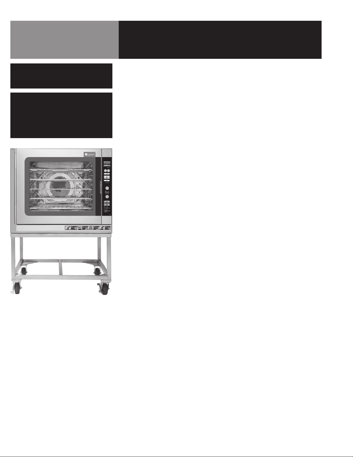
Your Groen Combination Oven is a stainless steel cooking chamber consisting of an air
heating compartment with fan, a boilerless steam generator, and a control compartment
which houses electrical components.
All major components of the Combination Oven are encased in a heavy duty stainless
steel cabinet. The cabinet is lined with thick ceramic insulation. A
removable drip tray is located beneath the door.
Operator controls are located on the right front of the unit, except for the manual gas
shut-off valve, which is on the back left side near the top of the of the unit.
Standard controls let you operate the unit in any one of four cooking modes:
1. As a convection oven
2. As a self-contained pressureless steamer
3. As a combination oven-steamer with low humidity
4. As a combination oven-steamer with high humidity
Cooking chamber size and pan capacities are:
10 steam table pans (12 x 20 x 2½”)
or 10 full-size (18 x 26”) bake pans
The unit is available as single, double stack (2 high) units, and low height stand. The
optional stand must have casters.
Optional stands are available for single and double stack (2 high) units. The optional
stand must have casters. All units are intended to slide under a kitchen hood installed
with 78” clearance to floor.
Controls and monitoring displays for cooking times, operating mode and temperature
selection are on the control panel. The upper portion of the panel has a text information
display. Below it are the touch pads, indicator lights, temperature and time selector knobs
and displays, the power ON/OFF switch, and an hour meter to log operating hours.
A digital readout shows the selected temperature, which is entered by turning a knob.
Another digital readout shows the remaining time on an electronic ‘kitchen timer.’ The
time is adjusted by turning a dial knob.
2 wash spray nozzles on the rear inside wall of the unit sprays the interior walls as part
of the semi-automatic cleaning system.
The air heating space is separated from the cooking chamber by removable rear and
bottom partitions. The compartment which contains the unit’s automatic controls and
other electrical components is on the right side of the unit, and is accessed by removing
the right outside panel.
4 OM-CBE-10G
Page 5
Equipment Description
The bottom partition prevents food particles from falling into the water reservoir of the
boilerless steamer. Excess water and food particles falling down are collected on this
partition. A water drain is located under the removable bottom partition. Boilerless
reservoir water and cleaning water drains from the permanent floor to the stainless steel
drain pipe outside the oven. The drain pipe includes a spray condensor which suppresses
any steam escaping from the chamber and a drain box.
The unit is provided with two air and steam vents. One is to prevent internal pressure
build-up. This vent pipe exit is located at upper left corner of the unit (just above the rear
partition) and is visible from the rear of the unit. The other steam vent is from the drain
line on lower rear right and is attached to the water and overflow drain. This allows any
steam from the drain water to exhaust above the oven top. Both of these vents must be
exhausted above the oven flue and located underneath a kitchen vent hood.
BURNER FIRING RATES
INPUT RATES, BTU/HOUR
MODE
Oven
Steam
Combo
*Manifold Pressure
NATURAL GAS
at 3.5” W.C.*
75,000 75,000
75,000 75,000
75,000 75,000
at 10.0” W.C.*
LP GAS
OM-CBE-10G 5
Page 6
Inspection & Unpacking
CAUTION
SHIPPING STRAPS ARE UNDER TENSION AND
CAN SNAP BACK WHEN CUT.
CAUTION
THIS UNIT IS VERY HEAVY. YOU SHOULD
GET HELP AS NEEDED AND USE MATERIAL
HANDLING EQUIPMENT TO REMOVE THE UNIT
FROM THE SKID AND MOVE IT TO ITS PLACE
OF INSTALLATION.
Your Combination Oven will be completely assembled in a carton and attached to a skid.
On receipt, inspect the carton and crate carefully for exterior damage.
Carefully cut the straps around the carton and detach the sides of the carton from the skid.
Pull the carton up off the unit. Be careful to avoid personal injury or equipment damage
from nails and sharp pieces of wood or staples which might be left in carton walls.
Write down the model number, serial number and installation date and keep this information
for future reference. Space for these entries is provided at the top of the Service Log in
the back of this manual.
When starting installation, use material handling equipment to lift the unit straight up off
the skid. Check packing materials to make sure loose parts are not discarded with the
material.
6 OM-CBE-10G
Page 7
Water Quality and Treatment
CAUTION
A FILTER SUITABLE FOR REMOVING FERRITE
COMPOUNDS IS RECOMMENDED WHEN THE
WATER SUPPLY HAS HIGHER THAN 50 PPM
OF IRON CONTENT. FAILURE TO DO SO COULD
CAUSE RUSTING OF THE OVEN CAVITY.
It is essential to supply the steam generator with water that will not form scale. Even
though the boilerless steam generator is engineered to minimize scale formation, scale
development depends on the hardness of your water and the number of hours you
operate the equipment each day.
Most water supplies contain minerals which form scale. It is this scale which could lead
to an early component failure.
Your local water utility can tell you about the minerals in your water. The water going
to the steam generator should have between 30 and 40 parts per million (ppm) total
dissolved solids (TDS) and should have a pH (acidity rating) of 7.0 to 9.0.
Please follow these simple precautions:
1. The best way to prevent scale is to use a Groen PureSteam™ Water Treatment
System which has been specifically designed for Groen steamers and combination
ovens. Do not rely on unproven water treatments sold for scale prevention and
removal. They are not specifically designed to work with Groen steamers
and combination ovens.
2. A well-maintained water treatment system and a regular cartridge replacement
schedule is essential.
3. Using a Groen water treatment system will provide longer steam generator/boiler
life, higher steam capacity, and reduce maintenance requirements.
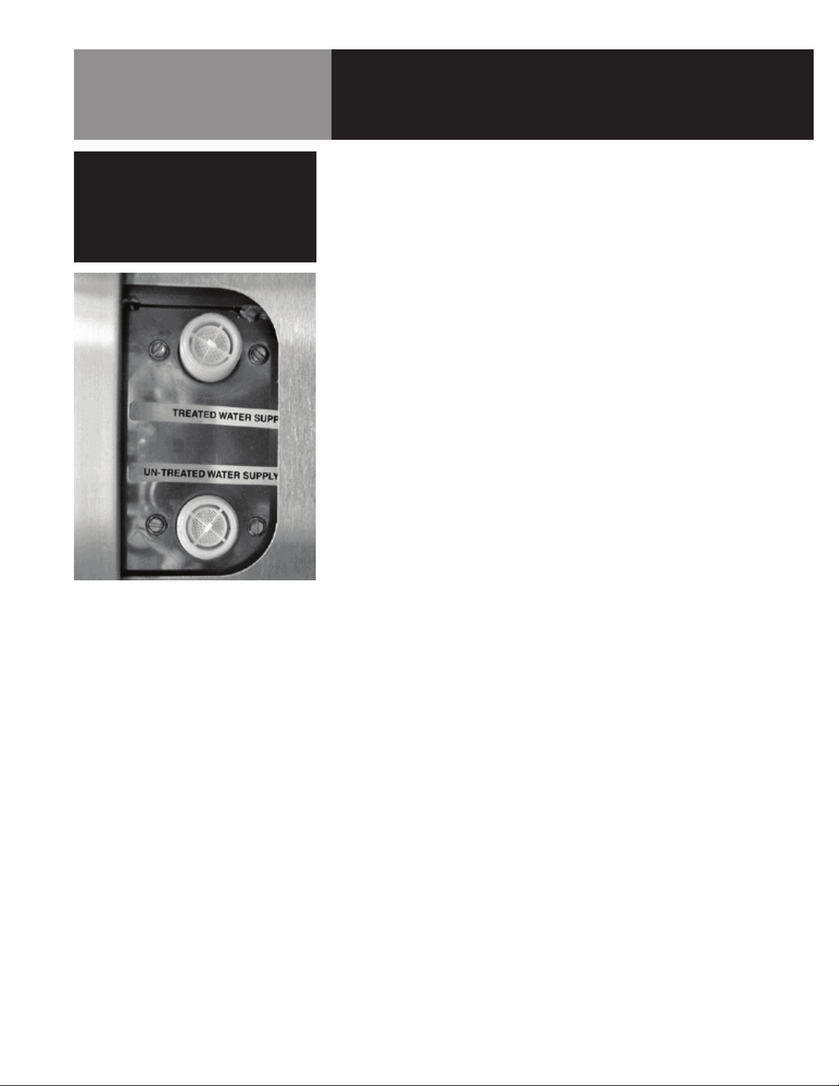
Standard water connections for steam
generator and drain spray condenser.
4. If you notice a slowdown in steam production, check the unit’s bottom for scale
build-up. This could be an indication that the water treatment cartridges need
replacing. Heavy scale reduces the unit’s ability to boil water, and can even cause
component failure.
MINIMIZE SCALE PROBLEMS BY INSTALLING AND MAINTAINING A GROEN
WATER TREATMENT SYSTEM AND BY DELIMING THE STEAM GENERATOR/BOILER
REGULARLY.
Groen Combination Ovens features two separate water inlets — one for the steam
generator (for treated water), the other for the spray condenser (untreated water) and
semi automatic wash cycle. The second intake will reduce water treatment requirements
resulting in significant savings.
The dual water connections are on the rear of the unit.
OM-CBE-10G 7
Page 8
Installation
WARNING
THE UNIT MUST BE INSTALLED BY
PERSONNEL WHO ARE QUALIFIED TO WORK
WITH GAS, ELECTRICITY AND PLUMBING.
IMPROPER INSTALLATION CAN CAUSE
INJURY TO PERSONNEL AND/OR DAMAGE
TO THE EQUIPMENT. THE UNIT MUST
BE INSTALLED IN ACCORDANCE WITH
APPLICABLE CODES. THE UNIT MUST BE
INSTALLED BY A LICENSED PLUMBER OR
GAS FITTER WHEN INSTALLED WITHIN THE
COMMONWEALTH OF MASSACHUSETTS.
CAUTION
DO NOT INSTALL THE UNIT WITH THE REAR
VENTS BLOCKED OR WITHIN 6 INCHES OF
A HEAT SOURCE SUCH AS A BRAISING PAN,
DEEP FAT FRYER, CHARBROILER OR KETTLE.
TO AVOID DRAINAGE PROBLEMS, LEVEL THE
UNIT AND PITCH IT SLIGHTLY TO THE REAR.
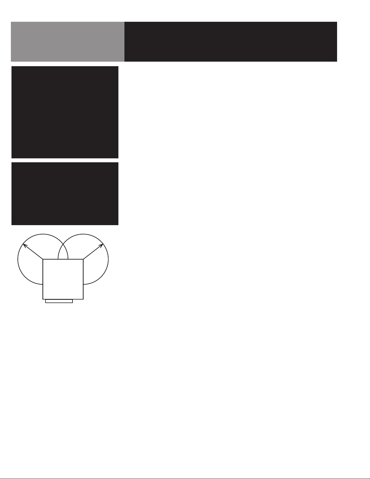
18 - inch
457 mm
radius
CBE -10G
(top view)
18 - inch
radius
457 mm
1. Installation
Minimum Clearances: The Combination Oven requires the following minimum
clearances to any surface, combustible or non-combustible. Floor clearance is 6
inches minimum to bottom of frame.
Right Side 6 inches
Left Side 6 inches
Rear 0 inches for motor
Recommended Service Clearances:
Right Side 14 inches
Left Side 6 inches
Rear 24 inches
Front 36 inches
Steam Free Zone: The Combination Oven can be damaged by steam from
external sources. Do not install the unit steam venting drain. Ensure that steam is
not present in an area bounded by the footprint of the unit and a circle 18 inches
in radius about the right and left rear corner of the unit (see figure to the left).
Install and operate the gas appliance in a well ventilated area. Adequate air must
be supplied to replenish the air used for combustion. Ventilation must employ a
vent hood and exhaust fan with no direct connection between the vent duct and
the combination oven flue. Installation must conform with local codes and/or with
the National Fuel Gas Code, ANSI Z223.1/NFPA-54 (latest edition) or the Natural
Gas and Propane Installation Code CSA B 149.1 as applicable.
Any item which might obstruct or restrict the flow of air for combustion and
ventilation must be removed. Do not obstruct the flue cover or rear vents after
installation.
8 OM-CBE-10G
THE AREA DIRECTLY AROUND THE APPLIANCE MUST BE CLEARED OF ALL
COMBUSTIBLE MATERIAL. FAILURE TO FOLLOW THESE INSTRUCTIONS CAN
CAUSE BODILY INJURY AND/OR PROPERTY DAMAGE.
NOTE: The unit must be installed on a stand with casters.
The unit must be disconnected from the gas supply system during any pressure
testing of that system which has test pressures in excess of ½ psi (3.45 kPa).
The unit must be isolated from the gas supply piping system by closing its individual
manual shutoff valve during any pressure testing of the gas supply piping system at
test pressures equal to or less than ½ psi (3.5 kPa).
Page 9

Installation
CAUTION
THIS OVEN REQUIRES A 15 AMPERE OUTLET
AND CIRCUIT. TO PREVENT NUISANCE TRIP
OF CIRCUIT BREAKER, IT IS RECOMMENDED
THAT THE ELECTRICAL CIRCUIT SHOULD NOT
BE SHARED WITH OTHER APPLIANCES.
WARNING
FOR UNIT INSTALLED ON CUSTOMER
SUPPLIED STANDS, CASTERS ARE REQUIRED
WITH RESTRAINING REQUIREMENT AS LISTED.
Eyebolt connector on the back of the unit.
2. Electrical Supply Connection
Provide 115 VAC, 60 HZ, 1 PH, 15 AMP service. Bring wire in through hole in
the lower left back panel. Each cavity requires a separate cord for connections.
Local codes and/or the National Electrical Code should be observed in accordance
with ANSI/NFPA 70. AN ELECTRICAL GROUND IS REQUIRED. The wiring diagram
is located in the service compartment and in this manual. Maximum load is
12 AMPs. In Canada, provide electrical service in accordance with the Canadian
Electrical Code, CSA C22.1 Part 1 and/or local codes.
3. Gas Supply Connection
Connection to the gas supply shall be ½” NPT pipe size. Double stack units
require 2 separate gas connections.
NOTE: For operation at high altitudes (2000’ and above), please consult Groen
Engineering Department.
Ratings for Gas Combination Oven
*Measured at gas manifold
BTU
CBE-10G-NG 75,000 3.50” WC 5” WC 14” WC
*Operating
Pressure
MIN Incom-
ing Gas
Feed Rate
MAX In-
coming Gas
Feed Rate
CBE-10G-LP 75,000 10.0” WC 12” WC 14” WC
In Canada, the installation must conform to the Canadian Gas Code, CAN 1-B1 49,
Installation Codes for Gas Burning Appliances and Equipment and/or local codes.
After the unit has been connected to the gas supply, all gas joints must be checked
for leaks. Do NOT use flame checking for leaks. A thick soap solution or other
suitable leak detector should be used.
Unit Restraining Requirement
A. The installation shall be made with a connector that complies with the
standard for connectors for movable gas appliances. ANSI Z21.69.CSA
6.16, and a quick-disconnect device that complies with the standard for
quick-disconnect devices for use with gas fuel, ANSI Z21.41.CSA 6.9.
B. Adequate means must be provided to limit the movement of the appliance
without depending on the connector and the quick-disconnect device or its
associated piping to limit the appliance movement.
C. The location where the restraining device may be attached to the appliance
shall be in accordance with Groen specifications for the device. (see photo)
OM-CBE-10G 9
Page 10

Installation
WARNING
DO NOT CONNECT THE DRAIN DIRECTLY TO
A BUILDING DRAIN. BLOCKING THE DRAIN IS
HAZARDOUS.
CAUTION
DO NOT USE PLASTIC PIPE. DRAIN MUST BE
RATED FOR BOILING WATER.
D. Anchor restraining cable bracket to a secure structure. One of the preferred
locations is on the concrete floor using anchor bolts (not provided) as shown
in photo on left.
4. Water Connection(s)
Install a check valve to prevent back flow in the incoming cold water line, as
required by local plumbing codes. Water pressure in the line should be between
30 and 60 PSI. If pressure is above 60 PSI, a pressure regulator will be needed.
These pressures will provide the 1.5 gallons per minute required for proper
steamer function.
A ¾ inch female NH connector (garden hose type) is used to attach the water
supply to each inlet valve. Two (2) supply connections are required for each unit.
One must be treated water (see water treatment section for requirements) and the
other may be untreated water. Minimum inside diameter of the water feed line
is ½ inch. Use a washer in the hose connection. Do not allow the connection
to leak, no matter how slowly. Do not over-tighten hose connections.
COLD WATER PRESSURE 30 - 60 PSI.
SEE PAGE 6 FOR WATER TREATMENT REQUIREMENTS.
This equipment is to be installed to comply with the basic plumbing code of the
Building Officials and Code Administrators International, Inc. (BOCA) and the Food
Service Sanitation Manual of the Food and Drug Administration (FDA).
WATER TRAP
BUILDING DRAIN
IMPROPER DRAIN LINE CONNECTION
NOTE: Local code may also require an approved back flow prevention device.
5. Drain Connection
Preferred installation for proper operation is to pitch the unit slightly to the rear
(maximum ¼ inch). Do not pitch the unit’s floor towards the front.
There must be a free air gap between the end of the hose and the building drain. The
free air gap should be as close as possible to the unit drain. There must also be no
other elbows or restrictions between the unit drain and the free air gap.
Install the drain line with a constant downward pitch.
BUILDING DRAIN
10 OM-CBE-10G
AIR GAP
Page 11

Installation
W
DO NOT ALLOW WATER TRAPS IN THE LINE.
A TRAP CAN CAUSE PRESSURE BUILDUP IN
THE CAVITY, WHICH MAY CAUSE THE DOOR
GASKET TO LEAK.
PROPER DRAIN LINE CONNECTION - DRAIN
LINE MUST HAVE A CONSTANT DOWNWARD
PITCH OF AT LEAST ¼” PER FOOT. OBSERVE
LOCAL CODE REGARDING AIR GAP SPACING
AND DRAIN CONNECTIONS.
IMPORTANT
6. Factory-Stacked Units
This section is applicable only if you are installing factory stacked units.
Installing stacked combination ovens is similar to installing a single unit. The units
are stacked and assembled at the factory.
A. Water Connection
The same water supply connection is used for both units. At the water
inlet valve a ¾ inch female NH connector (garden hose type) is used for the
waters supply.
B. Electrical Supply Connection
Separate electrical connections will be required for each unit to be stacked.
Each steamer unit must have it’s own branch circuit protection.
C. Gas Connection
Separate gas connections are required for both units. Gas supply must be
adequate under all conditions as listed on the previous page.
D. Drain Connection
For all factory-stacked units, a 1-½ inch ID hose is attached to the unit drain.
It must be rated for boiling water.
OM-CBE-10G 11
Page 12

Initial Start-Up
WARNING
WHEN YOU OPEN THE DOOR, STAY AWAY
FROM STEAM COMING OUT OF THE UNIT. THE
STEAM CAN CAUSE BURNS.
After the Combination Oven has been installed, test it to ensure that the unit is operating
correctly.
Remove all literature and packing materials from the interior and exterior of the unit.
1.
2. Make sure the water supply line is open.
3. Make sure that the gas supply line is open and that the manual knob on the main
gas valve is turned to the “ON” position. This valve is at the back left side near the
top of the unit.
4. Turn “ON” electrical service to the unit. The oven will not operate without electrical
power. Do not attempt to operate the unit during a power failure.
NOTE: The door MUST be closed for the main burner to work.
5. To turn unit on, press the ON switch on the control panel.
6. When any of the four (4) cooking modes are selected, the main burners will ignite
automatically. The unit will indicate that it’s ready to cook within 25 minutes or
less. The ready condition is indicated as follows:
• In oven mode - Temperature display (red LED) will stop flashing.
• In Hi or Lo combination mode - Temperature display (red LED) will stop flashing.
• In steamer mode - The dashes in temperature display (red LED) will stop
flashing and beep.
7. In order to use the timer -
• To set or change time, rotate the knob to desired setting.
• Press START TIMER to start the timer.
• At the end of time cycle the beeper will sound and the red CANCEL TIMER light
will flash.
• To stop flashing push CANCEL TIMER button at top.
NOTE: Once the timer has started it will lock the temperature knob.
8. Press the LIGHT button to turn on interior lights. The lights will automatically turn
off after aproximately 30 seconds.
9. If the unit operates as described, the unit is functioning correctly and ready for USE.
NOTE: For operation at high altitudes (2000 ft. and above), please consult the
Groen Engineering Department.
12 OM-CBE-10G
Page 13

Information
Display
Console
Cancel
Beeper
Start
Timer
Select To Cook
In Steamer
Mode
Push To Cook
In Combo Mode
(default is Lo steam)
Select High or Lo
Steam in Combo
Mode
Push To Cook In
Oven Mode
Cavity Temp In
Deg F
Temp Knob To
Set Cooking
Temperature
Controls
Information Display Console: This is a two line display that shows various operating
functions of the unit and other operating information.
Start: Push this button to start kitchen timer (see Timer on left).
Cancel: Push this button to shut off the beeper after timer times out.
Steam: Push to cook in convection steamer mode.
Combo: Push to cook in convection oven/steamer combination mode, then select;
HI - When this button is pushed, the oven cooks in a high humidity environment
LO - When this button is pushed, the oven cooks in a low humidity environment
NOTE – Default is LO (if HI or LO is not pushed).
Oven: Push to cook in convection oven mode.
Temperature Display:
A) Convection oven and combination cooking modes –
Shows set temperature in °F
Flashes until the set temperature is reached during pre-heat
B) Steamer cooking mode –
Shows dashes
Flashes until steamer is ready during pre-heat
Temperature Knob: Turn to set cooking temperature in oven and combination cooking
modes. Maximum temperature that can be set is 450°F and the minimum temperature
that can be set is 200°F.
Timer Display: Shows remaining time when kitchen timer is operating. Beeper sounds
when remaining time is zero. The two dots on display flash when timer is in use.
Time Display
Timer Knob To Set
Time
Select Low or High
Fan Speed
For Crisping
Products
For Rinsing Oven
Cavity
Turn Inside Lights On
For 30 Seconds
Main Power ON/
OFF Switch
Hour Meter
Timer Knob:
Turn to set kitchen timer. Time can be set from 1 minute 9 hours 59 minutes.
Push ‘Start’ button to start timer count. Time setting can not be readjusted (higher or
lower) during the timing cycle. Beeper sounds when the set time cycle is complete. Push
‘Cancel’ to stop the beeper.
Fan Speed: Convection fan can be operated at high or low speed. When a fan speed is
not selected, (default) the fan operates at high speed. Low speed is recommended for
cooking delicate products.
CrispEase™: Push this button in COMBO or OVEN mode to vent excess moisture and
allow crisping of surface of cooked product.
Light: Push this button to turn interior oven lights “ON” The light will automatically shut
off after five seconds.
Clean: Push this button to initiate the unit’s wash spray segment of semi-automatic
cleaning cycle. Familiarize yourself thoroughly with the cleaning procedure on page 2021 of this manual before using the clean function.
Power ON/OFF Switch: This rocker switch is the main power switch for the oven. Push
the ON side to start the unit and OFF side to shut unit down. It is recommended that this
switch be used once or twice per day at the beginning of cooking period.
Hour meter: Shows the unit’s total hours of operation.
OM-CBE-10G 13
Page 14

Operation
CAUTION
WHEN THE UNIT IS MOVED FROM ITS ORIGINAL
POSITION FOR ANY CLEANING OR SERVICE, THE
HOOKS ON RESTRAINING CABLE ASSEMBLY
MUST BE RECONNECTED AT BOTH ENDS.
DETAILED INSTRUCTONS FOR RE-CONNECTION
TO THE APPLIANCE ARE SHOWN UNDER
“INSTALLATION” SECTION, ITEM 3.
1. To Light
A. Open gas valve on rear left of unit.
B. Push power switch to ON. The display will show SELECT MODE and PRE-
HEATING.
C. Select the desired operating mode. If STEAM was pushed while PREHEATING
was displayed the TEMPERATURE display will show three blinking dashes
until the temperature rises above 230°F.
1. For STEAM mode press the STEAM button.
a. The STEAM indicator will light. After that the display will show three
steady dashes indicating that the steaming temperature has been
reached (the ready condition).
2. For OVEN mode press the OVEN button.
a. The OVEN indicator lights. Adjust the TEMPERATURE knob (the upper
knob) for the desired cooking temperature; the lower limit is 200°F,
the upper limit is 450°F.
3. For COMBO mode press COMBO button.
a. The COMBO and LO moisture level indicators light. Adjust the
TEMPERATURE knob (the upper knob) for the desired cooking
temperature; the lower limit is 200°F, the upper limit is 450°F. If the
cavity temperature is more than 20°F below the selected temperature
the TEMPERATURE display flashes until the temperature is within
20°F of the selected temperature (this signals the ready condition).
b. Push Moisture Level HI. The two side reservoirs fill and the center
reservoir empties. The TEMPERATURE knob operates the same way
as in COMBO LO except that the upper limit is reduced to 350°F.
c. Select Fan Speed HI or LO by pressing Fan Speed HI or Fan Speed LO.
4. In either OVEN or COMBO mode, pressing the CRISPEase™ button
increases moisture venting from the cavity and boosts oven heating by
5000 BTU, while also draining reservoirs to eliminate additional moisture
addition.
2. To Re-Light
A. Push power switch to OFF. Wait 5 minutes, then repeat step 1.
3. To Shut-Off
A. Push power switch to OFF.
B. Close gas valve on rear left of unit.
14 OM-CBE-10G
Page 15

Operation
4. Cleaning Instructions
A. Do not use a detergent or oven cleaner that has chlorine solution, is chlorine
based, has sulfamic acid or has greater than 30% phosphoric acid.
B. After each clean cycle check the interior to make certain that all cleaning
residue has been rinsed off before installing racks or resuming cooking.
C. Once started, if there is a water supply or power supply interruption to
the unit then the clean and rinse cycle must be repeated before resuming
cooking.
D. When handling cleaner or detergent to be added:
1. Always wear suitable gloves and protective safety glasses. Failure to do
so can cause serious burns.
2. Take precautions to keep chemicals from contacting your skin.
3. Keep the chemical(s) away from the door gasket and front control panel
gasket. Failure to do so can drastically reduce gasket life.
E. Clean mode cannot be started while in any of the cooking modes. If oven is
in any cooking mode, press that mode button to deselect and go to stand-by
mode.
F. To select clean mode press the CLEAN button.
G. Follow the instructions on the display.
NOTE: SEE DETAILED INSTRUCTIONS IN THE CLEANING AND DELIMING
INSTRUCTIONS.
5. Deliming Instructions
A. Do not use a detergent or oven cleaner that has chlorine solution, is chlorine
based, has sulfamic acid or has greater than 30% phosphoric acid.
B. After each delime cycle check the interior to make certain that all deliming
residue has been rinsed off before installing racks or resuming cooking.
C. Once started, if there is a water supply or power supply interruption to
the unit then the clean and rinse cycle must be repeated before resuming
cooking.
D. When handling delimer or detergent to be added:
1. Always wear suitable gloves and protective safety glasses. Failure to do
so can cause serious burns.
2. Take precautions to keep chemicals from contacting your skin.
3. Keep the chemical(s) away from the door gasket and front control panel
gasket. Failure to do so can drastically reduce gasket life.
OM-CBE-10G 15
Page 16

Operation
E. Recommended quantity of delimer to be used - 1/3 to 1/2 cup per each
reservoir or 1 cup evenly dispersed in all reservoirs. Use Unified Brands Part
Number 140513 or equivalent delimer.
F. Remove racks and steam lids from inside the oven.
G. Delime mode cannot be started while in any of the cooking modes. If oven is
in any cooking mode, press that mode button to deselect and go to stand-by
mode.
H. To select delime mode press the LIGHT button, and then press the CLEAN
button.
I. Follow the instructions on the display.
NOTE: DELIMING CYCLE IS APROXIMATELY 30 TO 45 MINUTES.
SEE DETAILED DESCRIPTION IN CLEANING AND DELIMING INSTRUCTIONS.
6. When the unit is to be disconnected from gas supply and moved for servicing
and/or cleaning, the gas restraining cable hook must be disconnected first (see
“Installation” page, item 3 - Gas Connection). After the unit is returned to its
original position, the gas hose and the restraining cable must be reconnected.
7. Any maintenance and repair to the unit must be performed by qualified service
personnel. It is recommended that all service be performed by Groen or their
authorized agent. Contact factory to locate a qualified agent.
8. To clean the exterior of the unit use a good grade of stainless steel cleaner and a
cloth to clean the surface of the exterior. Use glass cleaner to clean the exterior
glass surface. DO NOT SPRAY WITH HIGH PRESSURE HOSE ON THE EXTERIOR
OF THE UNIT.
16 OM-CBE-10G
Page 17

Sequence of Operation
1. Preheating
When the power switch is turned on the burners light and raises the cavity
temperature to 200°F (the set point). No cooking mode has been selected and the
display shows SELECT MODE on the first line and PREHEAT on the second line.
When the power switch is turned on from a cold start the unit turns on the center
burner first and the cavity fan is off to allow the flue to heat gradually. After a few
minutes all three burners will light.
When the temperature rises above 180°F (20°F below the set point) PREHEAT
disappears from the display. The fan is allowed to operate at the selected speed.
The temperature continues to rise to the set point at which time the burners will
cycle on and off to keep it there. At any time the user may select any cooking
mode. However, if steam or combo modes are selected water will not enter the
reservoirs until after the unit is heated.
2. Flame-out detection
When the oven is started the cavity temperature should rise above 135° in ten
minutes. If the burner didn’t start or has gone out the temperature at that time will
be too low. The message “Burner not on. Relight” will be displayed and the oven
will turn off. Follow the RE-LIGHT instructions.
3. Ready indication
The ready condition is satisfied (the oven is ready) when the set cavity temperature
is reached. In the idle condition (no cooking mode selected) the set point is 200°F.
In steam mode it is set to generate steam. In combo and oven modes it is set
by the user. When the oven is not ready, the word PREHEAT is displayed and
the temperature display flashes. Once the oven comes up to ready PREHEAT
disappears and the temperature display stops flashing. If the door is opened and
the oven is loaded with cold food the cavity temperature will fall. However, since
the ready condition has already been met the temperature display will not flash.
If the cooking mode is changed then the temperature display will resume flashing
if the current cavity temperature is more than 20°F below the new set point,
that is, the oven is not ready. Once ready state is achieved with the new settings
the flashing will stop. The same sequence occurs if the temperature setting is
changed.
4. Water level
If combo or steam mode is selected one or more of the reservoirs will fill with
water (after the unit is heated). There are two water level sensor probes, one for
the center reservoir and one for the right reservoir. When the water level drops
below a sensor probe (boils off) the associated water valve opens and refills the
reservoir. Whenever a fill or drain valve is first opened a timer controls the fill and
drain times. If the water level has not changed when this timer finishes an error
message is displayed telling which valve (fill or drain) in which reservoir (1 or 2)
took too long to change. If it takes too long to fill or drain a reservoir it could mean
that the sensor probe is contaminated and should be cleaned. Fill timeout could
also mean that the water pressure is very low or the main water valve is turned
off. Drain timeout could mean that the drain is plugged and should be cleaned.
OM-CBE-10G 17
Page 18

Wash spray nozzle.
Sequence of Operation
5. Door
When the door is open for five minutes or more the burners are turned off. As soon
as the door is closed the burners resume normal operation.
Whenever the door is open the cavity fan is stopped and the timer (if running) is
paused.
During the clean cycle the rinse water is stopped whenever the door is open.
6. Cavity fan
The cavity fan normally operates at high speed. Pushing the Fan Speed LO button
selects the low speed. Whenever the cooking mode is changed the fan speed is
automatically set to high.
7. Timer
When the power switch is turned on the timer is paused, the colon (:) in the TIMER
display does not flash to indicate pause. Adjust the TIMER knob (the lower knob)
for the desired cooking time in hours and minutes. Push START to allow the timer
to run, the colon flashes indicating that it is running. It also locks the temperature
knob. At the end of the timing period the beeper sounds and the CANCEL indicator
flashes. Push CANCEL to stop the beeper. Note that this is all the timer does; it is
a simple kitchen timer. It does not stop any cooking process, it simply alerts the
operator that the timer has timed out.
8. Light
When the LIGHT button is pushed the door lights turn on to illuminate the cavity.
When the button is released the lights stay on for five seconds and automatically
turn off.
9. Condensate spray
When a steam-water valve is first turned on a large puff of steam may be created
if the water is sent to a hot reservoir. Part of this puff of steam goes out the
overflow drain. During this time the condensate spray is turned on to condense
the steam and cool drain water.
When a drain valve is opened it discharges hot water into the oven drain. During
this time the condensate spray is turned on for a longer period to cool the drain
water.
The condensate spray is turned off when not draining to conserve water.
10. Spray Nozzle
The spray nozzle is used in the clean cycle to rinse the cavity walls. Both of the
nozzles should be oriented with the flats vertical and the slots up. (see photo)
18 OM-CBE-10G
Page 19

Maintenance
It is important to properly maintain this equipment. A regularly maintained unit will
provide many years of trouble free operation. Recommended maintenance schedule
is outlined below:
1. Daily
A. Clean the interior and exterior (outer panels) of the oven per cleaning
procedure described in this manual.
B. Drain, clean and air dry the condensate drip pan located below the door.
Liquid level probes.
C. Open the inner glass panel and check both inner and outer glass for cracks.
The inner glass pane should securely snap in place for proper operation.
Check for signs of loose fit. If cracks are found, do not operate the unit until
the glass is replaced.
2. Weekly
A. Delime the interior per deliming procedure described in this manual.
B. Remove all interior baffles as part of the cleaning procedure and clean the
liquid level probes with a non abrasive, stiff brush. Two (2) liquid level probes
are located on the rear wall of the unit below the fan. (see photo)
C. Open the inner glass panel and check the light assembly for proper operation
and fit.
3. Monthly
A. Check the hinges and other moving parts of the inner glass panel and outer
glass doors for smooth operation and signs of misalignment or wear. If the
door does not move freely or sags, do not operate the unit until corrected.
B. Check the door latch for smooth operation. If necessary lubricate the latch
spring with a food grade PTFE lubricant.
C. Check the door gasket at all four (4) corners and along its entire length
for cracks, cuts or abrasion. A leaking gasket could cause severe burns.
Replace the gasket as needed.
D. If your unit is equipped with Groen supplied stand and optional pan racks,
check the pan racks for a secure fit. If they are loose and not level, reinstall
them properly or call your authorized service agency.
OM-CBE-10G 19
Page 20

Cleaning
WARNING
WHEN HANDLING CLEANER OR DETERGENT
ALWAYS WEAR SUITABLE GLOVES AND
PROTECTIVE SAFETY GLASSES. FAILURE
TO DO SO CAN CAUSE SERIOUS BURNS.
TAKE PRECAUTIONS TO KEEP CHEMICALS
FROM CONTACTING YOUR SKIN. KEEP
THE CHEMICAL(S) AWAY FROM THE
DOOR GASKET AND THE FRONT CONTROL
PANEL GASKET. FAILURE TO DO SO CAN
DRASTICALLY REDUCE GASKET LIFE.
WARNING
AFTER EACH CLEAN CYCLE CHECK THE
INTERIOR TO MAKE CERTAIN THAT ALL
CLEANING RESIDUE HAS BEEN RINSED OFF
BEFORE INSTALLING RACKS OR RESUMING
COOKING.
Cleaning It is best to clean the oven when it is at room temperature. However, it may
be cleaned right after cooking.
1. First turn off whatever cooking mode is currently on by pushing its button. For
example, if the oven is in steam mode (the STEAM indicator is on) push the
STEAM button. The indicator will go out showing that no cooking mode is currently
selected.
2. If the oven is off turn it on with the power switch.
3. Push CLEAN.
4. The message OPEN DOOR appears in the display. When the door is open the
message changes to SPRAY CLEANER AND CLOSE DOOR.
5. When the door is closed the message changes to CLEAN MODE SOAK TIME and
the oven rests to allow the cleaner to work.
6. A counter in the second line of the display shows the number of seconds remaining
in each timed cleaning step.
7. Then the rinse valve opens (message CLEAN MODE RINSE TIME appears in the
display) to flush the cleaner off the cavity walls.
8. This is followed by a drain period (CLEAN MODE DRAIN TIME appears in the
display) followed by the rinse.
20 OM-CBE-10G
9. When this is complete the message CLEAN COMPLETE TIME LEFT is displayed and
the oven beeper sounds four times at 15 second intervals with a new message
displayed as OPEN DOOR. The oven turns itself off at the end of the fourth beeper
sound.
10. If the oven is hot at the beginning of the soaking period the message OPEN DOOR
TO COOL OVEN is displayed. While the door is open the message COOLING is
displayed.
11. When the oven has cooled sufficiently to allow it to continue the message CLOSE
THE DOOR is displayed.
12. The cleaning cycle starts with the message OPEN DOOR AND REMOVE RACKS.
At any time during the cleaning cycle the user may open the door and spray more
cleaner in the cavity. When the door is closed the cycle starts over with the soaking
period followed by the two rinses.
Once a cleaning cycle has been started all other cooking modes are inactive (locked
out). The cleaning cycle must run to completion before the oven will operate in the
cooking modes.
The oven may be turned off at any time during the cleaning cycle. When the oven is
turned on again it remembers that it was interrupted in the middle of the cleaning
cycle. The message PUSH CLEAN TO FINISH CLEANING appears in the display. No other
cooking mode buttons will operate. When the clean cycle is complete the oven turns off.
The oven can then be turned on and operate in any mode.
Page 21

Cleaning
WARNING
WHEN HANDLING CLEANER OR DETERGENT
ALWAYS WEAR SUITABLE GLOVES AND
PROTECTIVE SAFETY GLASSES. FAILURE
TO DO SO CAN CAUSE SERIOUS BURNS.
TAKE PRECAUTIONS TO KEEP CHEMICALS
FROM CONTACTING YOUR SKIN. KEEP
THE CHEMICAL(S) AWAY FROM THE
DOOR GASKET AND THE FRONT CONTROL
PANEL GASKET. FAILURE TO DO SO CAN
DRASTICALLY REDUCE GASKET LIFE.
WARNING
AFTER EACH CLEAN CYCLE CHECK THE
INTERIOR TO MAKE CERTAIN THAT ALL
CLEANING RESIDUE HAS BEEN RINSED OFF
BEFORE INSTALLING RACKS OR RESUMING
COOKING.
Deliming The oven may be delimed at any temperature. However, since it is necessary
to remove the steam lid from the inside of the cavity the oven should be allowed to cool
before starting the procedure. It is recommended that the oven delime cycle is complete
before cleaning.
1. First turn off whatever cooking mode is currently on by pushing its button.
2. If the oven is off turn it on with the power switch. Push LIGHT. While the LIGHT is
on push CLEAN. The message OPEN DOOR AND REMOVE STEAM LID appears in
the display. This indicates that the oven is in deliming mode. If the message OPEN
DOOR AND REMOVE RACKS appears it means that the LIGHT was not on while
CLEAN was pushed. You have another chance to put the oven in delime mode.
Push LIGHT again. While the LIGHT is on push CLEAN. The STEAM LID message
should appear.
3. Open the door and remove the steam lid from the bottom of the cavity. The display
message changes to ADD DELIMER AND CLOSE DOOR.
4. Water begins to fill the three reservoirs and the heaters turn on. Pour 1/3 cup of
delimer into each reservoir, one cup total. Close the door.
5. The message changes to DELIME MODE TIME LEFT. The oven will steam for 20
minutes and drain (display message is DELIME MODE DRAIN TIME).
6. At this time the oven is hot and the display message changes to OPEN DOOR TO
COOL OVEN.
7. When the door is opened the display message changes to COOLING.
8. When the oven has cooled sufficiently to allow it to continue the display message
CLOSE THE DOOR is displayed.
9. When the door is closed the oven enters the cleaning cycle at the first rinse step.
It rinses twice, displays CLEAN COMPLETE TIME LEFT, and turns itself off.
Once a deliming cycle has been started all other cooking modes are inactive (locked
out). The deliming cycle must run to completion before the oven will operate in the
cooking modes.
The oven may be turned off at any time during the deliming cycle. When the oven is turned
on again it remembers that it was interrupted in the middle of the deliming cycle. The display
message is PUSH CLEAN TO FINISH CLEANING. The oven enters the clean cycle at the rinse
step to remove all delimer from the reservoirs and it shuts itself off. It can then be turned on
and operated in any mode.
OM-CBE-10G 21
Page 22

Service Log
Model No: Purchased From:
Serial No: Location:
Date Purchased: Date Installed:
Purchase Order No: For Service Call:
Date Maintenance Performed Performed By
22 OM-CBE-10G
Page 23

NOTES:
OM-CBE-10G 23
Page 24

1055 Mendell Davis Drive • Jackson MS 39272
888-994-7636 • 601-372-3903 • Fax 888-864-7636
unifiedbrands.net
© 2010 Unified Brands. All Rights Reserved. Unified Brands is a wholly-owned subsidiary of Dover Corporation.
PART NUMBER 155492 REV D (12/10)
 Loading...