

Page 1
- 1 -
IMPORTS, INC.
3
/4 H.P. SHAPER
MODEL G1024
INSTRUCTION MANUAL
COPYRIGHT © 1994 BY GRIZZLY INDUSTRIAL, INC.
WARNING: NO PORTION OF THIS MANUAL MAY BE REPRODUCED IN ANY SHAPE
OR FORM WITHOUT THE WRITTEN APPROVAL OF GRIZZLY INDUSTRIAL, INC.
REVISED JUNE, 1994. PRINTED IN USA
DISCONTINUED MACHINE MANUAL DISCLAIMER
THE INFORMATION IN THIS MANUAL REPRESENTS THE LAST CONFIGURATION OF THE MACHINE BEFORE IT WAS DISCONTIN-
UED. MACHINE CONFIGURATIONS MAY HAVE CHANGED AS PRODUCT IMPROVEMENTS WERE INCORPORATED. IF YOU OWN AN
EARLIER VERSION OF THE MACHINE, THIS MANUAL MAY NOT EXACTLY DEPICT YOUR MACHINE . CONTACT CUSTOMER SERVICE
IF YOU HAVE ANY QUESTIONS ABOUT DIFFERENCES. PREVIOUS VERSIONS ARE NOT AVAILABLE ONLINE.
Page 2

- 2 -
TABLE OF CONTENTS
PAGE
I. INTRODUCTION..........................................................................................................1
II. COMMENTARY ..........................................................................................................1
III. SAFETY RULES FOR ALL TOOLS............................................................................2
IV. UNPACKING................................................................................................................4
V. PIECE INVENTORY ....................................................................................................5
VI. CLEAN-UP BEFORE ASSEMBLY..............................................................................6
VII. SITE PLANNING ..........................................................................................................6
A FLOOR LOAD............................................................................................................6
B WORKING CLEARANCES ........................................................................................6
VIII. ELECTRICAL SERVICE REQUIREMENTS................................................................7
A. GENERAL ................................................................................................................7
B. GROUNDING............................................................................................................7
IX. ASSEMBLY..................................................................................................................8
A. STAND......................................................................................................................9
B. FENCE ASSEMBLY ..............................................................................................10
C. SAFETY GUARD ..................................................................................................11
X. SAFETY PROCEDURES ..........................................................................................12
XI. ADJUSTMENT SECTION..........................................................................................15
A. FENCE....................................................................................................................15
B. SPINDLES ..............................................................................................................17
C. SPINDLE ELEVATION ..........................................................................................18
D. CUTTER DIRECTION ............................................................................................18
XII. RUB COLLARS ........................................................................................................19
A. HOW RUB COLLARS ARE USED ........................................................................19
B. EXAMPLES ............................................................................................................20
C. PATTERN WORK ..................................................................................................22
XIII. SHAPING ..................................................................................................................22
A. STRAIGHT STOCK ................................................................................................22
B. IRREGULAR SHAPING ........................................................................................22
Page 3

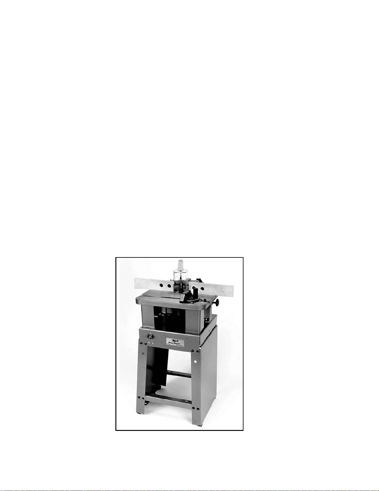
I. INTRODUCTION
We are proud to offer the Model G1024 Shaper. The Model G1024 is part of a growing Grizzly family of fine woodworking machinery. When used according to the guidelines set forth in this manual,
you can expect years of trouble-free, enjoyable operation and proof of Grizzly’s commitment to customer satisfaction.
The Model G1024 is intended for use in a home or small professional shop. This shaper features a
3
/4 H.P., 110 / 220V single phase motor and full reversing capabilities. The Model G1024 also fea-
tures a precision-ground cast iron table and
1
/2" spindle. This shaper operates at 10,000 RPM, giv-
ing you plenty of shaping flexibility at a very reasonable price.
A number of optional accessories for the Model G1024 are available through the Grizzly catalog.
They include a heavy-duty mobile base and a router bit spindle, which enable your shaper to use
most standard
1
/2" router bits.
We are also pleased to provide this instructional manual with the Model G1024 Shaper. This manual was written to guide you through assembly, review safety considerations and cover general operating procedures. It represents our latest effort to produce the best documentation possible. If you
have any constructive criticisms or comments you feel we should include in our next printing, please
write us at the address below.
Manager, Technical Documentation
Grizzly Industrial, Inc.
P.O. Box 2069
Bellingham, WA 98227
Finally, we stand behind our machines. We have two excellent regional service departments at your
disposal, should the need arise. If you have any service questions or parts requests, please call or
write us at the appropriate location listed below.
Grizzly Industrial, Inc.
1203 Lycoming Mall Circle
Muncy, PA 17756
Phone:(570) 546-9663
Fax:(800) 438-5901
E-Mail: techsupport@grizzly.com
Web Site: http://www.grizzly.com
II. COMMENTARY
To operate this, or any power tool, safely and efficiently, it is essential to become as familiar with its
characteristics as possible. Take as much time as necessary to become acquainted with the Model
G1024 Shaper. The time you invest before you begin to use this machine will be time well spent. Also,
read all of the safety procedures. If you do not understand something, do not operate this machine.
The specifications, drawings and photographs illustrated in this manual represent the Model G1024,
as supplied when the manual was prepared. However, owing to Grizzly’s policy of continuous
improvement, changes to the Model G1024 may be made at any time with no obligation on the part
of Grizzly.
- 3 -
Page 4

The information in this manual has been obtained from sources believed to be reliable and as up-todate as possible. While this manual is intended to be a substantial source of basic shaping information, it is by no means the last word on shaping. Instead, we have focused primarily on the proper assembly and adjustment of the machine – as well as some basic information on shaping procedures. We have also included some important safety measures which we believe to be essential to
this machine’s operation. While most safety measures are generally universal, Grizzly cautions that
each workshop is different and safety rules should be considered as they apply to your individual sit-
uation.
The shaper is a fundamental machine, capable of performing a wide range of work. Its primary function is to profile edges for moldings and cabinets. The shaper can also be used for making joints,
grooves, flutes and profiles in many different designs and shapes.
The shaper is designed for highly-skilled individuals who have an understanding of wood and how it
mills. A strong knowledge of woodworking is essential for the proper use of the shaper and its correct applications. We realize there are numerous kinds of cutters and specialized techniques used
to shape wood throughout the woodworking community. To list all of the techniques necessary to
operate a shaper correctly for specific applications would require many volumes.
If you are not familiar with shapers and their safe operation, we strongly suggest you obtain as many
books on the subject as you can. Grizzly has a number of fine books available on wood shaping. A
visit to the local library, or time spent browsing through back issues of woodworking magazines will
prove beneficial in gaining knowledge of shaper operations.
III. SAFETY RULES FOR ALL TOOLS
WARNING! As with all power tools, there is a certain amount of inherent danger associated with the
Model G1024 Shaper. Using the tool with respect and caution will considerably lessen the possibility of mechanical damage or operator injury. However, if normal safety precautions are overlooked
or ignored, injury to the operator or others in the area is possible.
There are certain applications for which this tool was designed. We strongly emphasize that this tool
should never be modified and/or used for any application other than that for which it was designed.
If you are confused about any aspect of this machine, do not use it until you have resolved any
questions you might have. The following are important safety rules for all tools:
1. KNOW YOUR POWER TOOL. Read the owner’s manual carefully. Learn the tool’s applications
and limitations, as well as its particular hazards.
2. KEEP GUARDS IN PLACE and in working order.
3. GROUND ALL TOOLS. If the tool is equipped with a three-prong plug, it should be plugged into
a three-hole grounded outlet. If an adapter is used to accommodate a two-prong receptacle, the
adapter plug must be attached to a known ground. Never remove the grounding prong.
4. REMOVE ADJUSTING KEYS AND WRENCHES. Make it a habit to check that keys and adjust-
ing wrenches are removed from the machine before turning it on.
- 4 -
Page 5

- 5 -
5. KEEP WORK AREA CLEAN. Cluttered areas and benches invite accidents.
6. AVOID DANGEROUS ENVIRONMENTS. Do not use power tools in damp or wet locations or
expose them to rain. Keep your work area well lighted.
7. KEEP CHILDREN AND VISITORS AWAY. All children and visitors should be kept a safe dis-
tance away from your work area.
8. MAKE WORKSHOP CHILD-PROOF with padlocks, master switches, or by removing starter
keys.
9. DO NOT FORCE TOOL. Tools work better and more safely when they are allowed to work at
their own speed.
10. USE THE RIGHT TOOL. Do not use a tool or an attachment to do a job it wasn’t intended for.
11. WEAR PROPER APPAREL. Do not wear loose clothing, gloves, neckties, or jewelry that might
get caught in moving parts. Non-slip footwear is also recommended. Wear a hat or other protective head wear if your hair is long.
12. USE SAFETY GLASSES AND EAR PROTECTION. Also use a dust mask if the cutting oper-
ation is dusty.
13. SECURE YOUR WORK. Use clamps or a fixture to hold your work. It is safer than using your
hands and frees up both hands for operating the tool.
14. DO NOT OVERREACH. Keep proper footing and balance at all times.
15. MAINTAIN TOOLS IN TOP CONDITION. Keep tools sharp and clean for best and safest per-
formance. Follow instructions for lubricating and changing accessories.
16. DISCONNECT TOOLS FROM POWER before servicing and when changing accessories, such
as blades, bits and cutters.
17. USE RECOMMENDED ACCESSORIES. Consult the current catalog for recommended acces-
sories. The use of improper accessories may be hazardous.
18. AVOID ACCIDENTAL STARTING. Make sure the switch is in the “OFF” position before plug-
ging in the cord.
19. NEVER STAND OR LEAN ON TOOL. Serious injury could occur if the tool is tipped or if the
cutting tool is accidentally contacted.
20. CHECK DAMAGED PARTS. Before further use of the tool, any part or guard that is damaged
should be promptly repaired or replaced. Do not operate the machine until you are certain it is
in perfect running condition. Failure to follow this precaution could result in further mechanical
damage and operator injury.
21. DIRECTION OF FEED. Always feed your work against the direction of blade or cutter travel.
Workpieces fed in the same direction as the cutter travel could be forced out of your control.
Page 6
22. NEVER LEAVE THE TOOL RUNNING UNATTENDED - TURN POWER OFF. Do not leave the
tool until it comes to a full stop.
23. DRUGS, ALCOHOL, MEDICATION. Do not operate the tool under the influence of drugs, alco-
hol, or any medication. Never operate machinery when overly fatigued.
IV. UNPACKING
The Model G1024 Shaper is shipped from the factory in heavy-duty cardboard packaging. Carefully
remove the cardboard box by cutting through the box at its base. The top of the box can then be lifted off and set aside while you make your inspection of the machine. You can use the box, turned
upside down, as a receptacle for other packing materials as you prepare to set up the shaper.
If you find the machine is damaged after you’ve signed for delivery and the truck and driver are
already gone, you will need to file a freight claim with the carrier. Save the containers and all packing materials for inspection by the carrier or their agent. Without the packing materials, filing a freight
claim can be difficult. If you need advice regarding this situation, please call us.
Caution: The shaper weighs a hefty 155 pounds in its packaging. DO NOT over-exert yourself while
unpacking or moving this machine. Use a heavy-duty hand truck whenever possible while moving
the shaper. If it has to be moved up or down a flight of stairs, be sure the staircase is capable of supporting the combined weight of you and the shaper. Always get plenty of assistance when attempting to move the Model G1024.
Figure 1
- 6 -
Page 7

V. PIECE INVENTORY
Take a quick inventory of the parts and put them aside for assembly later.
Since the majority of the shaper is pre-assembled at the factory, there aren’t a lot of items to inventory. You should have the following:
• Shaper Unit
• Miter Gauge
• Spindle and Spacers
• Fence Boards
• Freehand Guard
• Bolt Bag (See below)
• Stand (4 pcs.)
• Adjustable Fence (3 pcs.)
The Model G1026 Bolt Box contains:
Rubber Feet (4)
Hex Bolt M6-1.0x12 (4)
Hex Nut M6-1.0 (4)
Flat Washer
3
/8
" (4)
Carriage Bolt M8-1.25x20 (16)
Nut M8-1.25 (16)
Flat Washer
3
/8" (16)
Slot Head Screws (4)
Flat Washer
5
/16
" (4)
Nut M8-1.25 (4)
The quantities given here are the minimum necessary to do the job; there may be some extra parts.
On the other hand, bolt bags are occasionally shipped from the factory with a nut or bolt missing.
You might consider replacing those items at your local hardware store. It’s not that we’re trying to
cheat you, but if you are short two screws that cost 10¢ apiece, it’s much cheaper to buy locally than
writing or phoning us. Even more, the time saved in shipping will mean that your shaper is ready to
use right away. Of course, if the number of items missing is extensive, or if the missing parts are
more substantial than nuts or bolts, we want to know about it, so we can eliminate problems for
future customers.
- 7 -
Page 8

VI. CLEAN-UP BEFORE ASSEMBLY
All of the unpainted surfaces on this machine – and a few of the painted ones – are coated with a
preservative oil, called Cosmolene, which prevents rust and corrosion during shipping. The coating
can be removed with paint thinner (mineral spirits) and a good supply of paper towels, although you
may find that careful scraping with a putty knife may be necessary where the coating is particularly
thick. Use caution when removing the coating with your putty knife to avoid scratching the table top
or painted surfaces on your shaper.
DO NOT use gasoline, lacquer thinner, acetone, or other highly-flammable solvents. The possibility
of flash fire or explosion is far greater and they don’t work much better anyway. Don’t use chlorinated solvents, such as perchloroethelene; they will lift the paint and ruin the shaper’s finish. Be careful when working around the drive belts. Any solvent that cuts grease will, in the long run, be harmful to rubber. While you are cleaning the shaper, please pay attention to the following rules:
1. Work only in a well-ventilated area.
2. Make sure there are no sources of open flame in your work area, such as pilot lights or woodstoves.
3. DO NOT smoke while you’re working.
4. Dispose of soiled towels in a proper manner to avoid fire and environmental damage.
Packaged in a separate box you will find a number of parts also covered with Cosmolene. The smaller pieces are best cleaned by placing them in a container of solvent for several minutes. After soaking, the remaining coating may be removed with firm pressure, using rags or paper towels. Some
pieces may have to be pried apart using a putty knife. Don’t forget to remove the fence assembly
and clean under it. Once again, dispose of waste properly.
VII. SITE PLANNING
When placing the planer in your shop, three considerations should be addressed; floor load, working clearances and electrical requirements. We’ll look at the first two requirements now and leave
the third for the next section.
A. FLOOR LOAD
Your Model G1024 Shaper represents a fairly large weight load in a small footprint. For planning purposes, the intended work area should be able to take a uniform distributed live load of 100 pounds
per square foot. Most commercial and residential floors are suitable for the Model G1024, though
some older wooden residential floors may require some additional build up to support both machine
and operator.
B. WORKING CLEARANCES
Working clearances will vary from one customer to the next, depending on individual requirements.
Place your shaper in a position that can handle your most ambitious shaping requirements. The
working area around the shaper should be lit well enough to eliminate shadows.
- 6 -
Page 9
VIII. ELECTRICAL SERVICE REQUIREMENTS
The Grizzly Model G1024 Shaper is furnished with a complete electrical package: A 3450 RPM
TEFC
3
/4 H.P. motor, ON-OFF starter switch, FORWARD/REVERSE switch and a cord set. The
motor is single phase and may be operated on 220/240V, as well as 110/120V.
A. GENERAL
The Model G1024 comes with a standard 110V cord and plug. Its motor draws 10 amps. While that
is not excessive, using the Model G1024 on a circuit that is already close to capacity could result in
overload. If possible, add a circuit specifically for the shaper. A 15-amp circuit breaker is ideal for the
Model G1024.
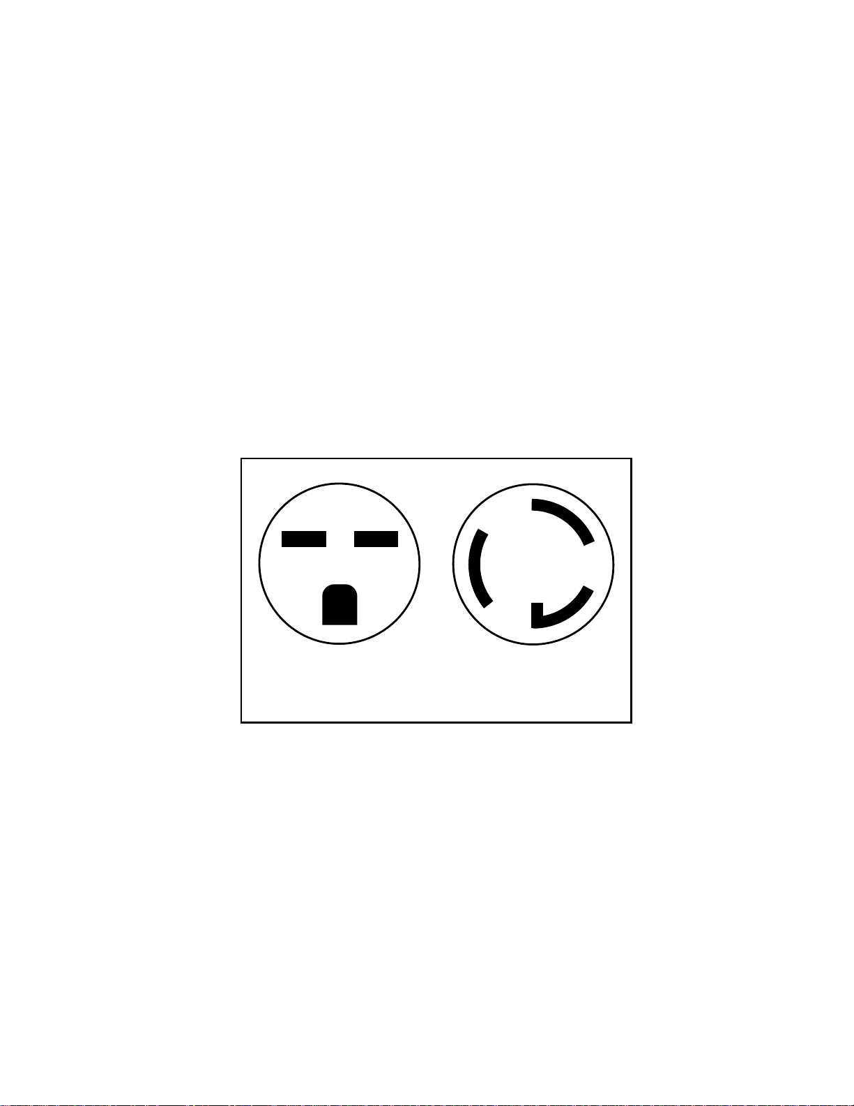
If you choose to re-wire the Model G1024 for 220V operation, use NEMA-approved connecter plugs.
See Figure 2 for examples of typical plug configurations. You should also check with our service
department for specific information on motor re-wiring requirements. Your local building department
or a licensed electrical contractor should also be able to help you if electrical requirements exceed
your understanding.
Figure 2
If you are plugging into an existing outlet, ensure that it is grounded. If not, it will be necessary to
run a separate grounding wire, #10 copper or larger, from the frame of the machine to the grounding stud at your service panel.
If you find it necessary to use an extension cord with your shaper, make sure its conductors are rated
at #10 or larger (for 220V). The cord should be rated for hard service (S-type jacket), with NEMAapproved connectors and a ground wire. An SJ-rated cord (#12-wire) should be sufficient for 110V.
CAUTION: Never cut the grounding pin from the plug. If you have problems with the electrics sup-
plied with the G1024, please contact our service department for assistance. Should you decide to
use a larger motor on the machine, DO NOT rely on the information above. Contact a licensed electrician or your local building department for proper wiring requirements.
- 7 -
B. GROUNDING
220 /240V
15A
NEMA 6-15
220 /240V
15A
NEMA 6-15
Page 10

IX. ASSEMBLY
Figure 3
Carefully lift the Model G1024 Shaper from its packaging. Be sure to get plenty of help when attempting to lift or move the machine. The Model G1024 Shaper has a shipping weight of more than 150
lbs. Make sure you have plenty of help when it comes time to move the machine. The Model G1024
is largely pre-assembled at the factory, so very little actual assembly is required. The motor is
already mounted and all wiring is in place. The remaining parts which require assembly are:
A. Stand
B. Fence
C. Safety Guard
The necessary assembly can be accomplished with a few hand tools. You’ll need a 12mm wrench,
a 14mm wrench, metric Allen wrenches and a Phillips head screwdriver. An adjustable wrench and
a metric socket set are helpful, but not essential, for assembly.
FENCE
SPINDLE LOCK
KNOB
MITER GAUGE
STAND
SAFETY GUARD
TABLE
ON/OFF SWITCH
- 8 -
SPINDLE
SPINDLE
ELEVATION
HOUSING
Page 11
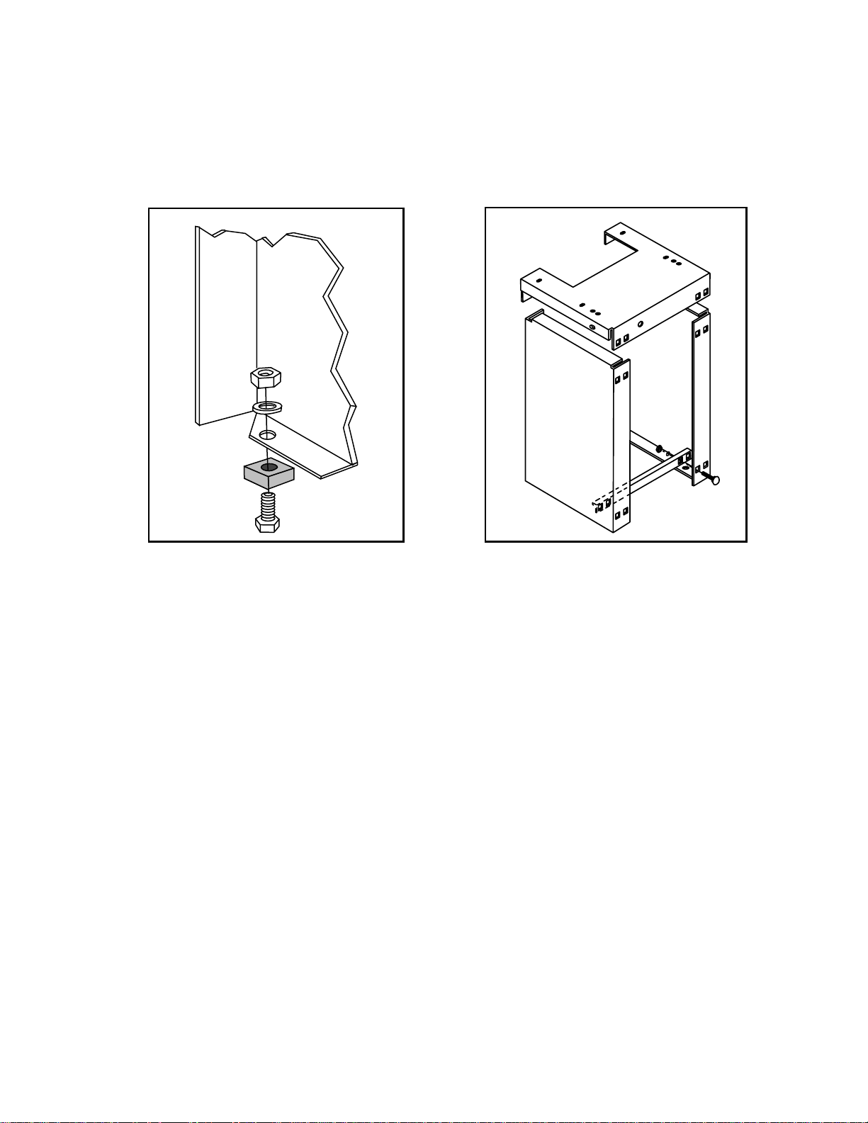
A. STAND
The Model G1024 Shaper features an A-frame stand. Begin assembling the stand by attaching the
four rubber feet to the bottom of the side panels with the M6-1.0x12 hex bolts, M6-1.0 hex nuts and
3
/8" flat washers provided. See Figure 4.
Figure 4
- 9 -
Figure 5
Once the rubber feet are connected, attach the crossbars loosely with the carriage bolts, nuts and
washers provided. See Figure 5. At this point, the stand will be somewhat wobbly. You will find it a
real help to have an assistant hold the stand in place while you attach the nuts and bolts.
When the stand’s sides and crossbars are in place, set the sheet steel top piece in place, as shown
in Figure 5. Make sure the square bolt holes are in alignment. When the bolt holes are correctly in
line, attach the remaining carriage bolts. When you’ve got all the bolts attached, tighten all the nuts
and bolts finger-tight. Working on a level surface, adjust the stand until the top piece is level. You
can verify your results by placing a carpenter’s level on the top, or measure diagonally from bottom
corner to top corner of the stand. When all of your measurements are equal, tighten all of your bolts.
After you’ve made sure the stand is level and secure, place the shaper assembly on the stand. Align
the holes on the bottom of the shaper with the holes in the top of the stand. Use the hex bolts, nuts
and washers provided to secure the shaper to the stand.
NOTE: Sheet steel will often “spring” after it has been fabricated at the factory, occasionally making
it difficult to line up precisely with other parts without a bit of effort. Don’t be surprised if the stand
requires a bit of “persuasion” to fit together. On the other hand, if the parts just don’t seem to work
together, try switching parts around (such as crossbars). If that doesn’t work, call our service department and we’ll try to help you remedy the situation.
Page 12
- 10 -
B. FENCE ASSEMBLY
The Model G1024 Shaper comes with a two-piece adjustable fence. Before attaching the fence unit
to the shaper table, you will want to “wood” it. The wood fence pieces included with the Model G1024
are pre-drilled and counterbored to allow the slotted mounting screws to rest below the wood surface
once they are tightened.
Most woodworkers like to replace the wood pieces on the fence with wider and thicker boards. This
gives the user greater stability and a larger bearing surface. The following procedure will ensure that
the fence is parallel with itself and square with the table.
1. Ensure that the bolts on each side are tight and adequately countersunk.
2. To align the wood fences, adjust one or both fence halves so they are in close alignment. Microadjust and check the alignment with a good straight edge.
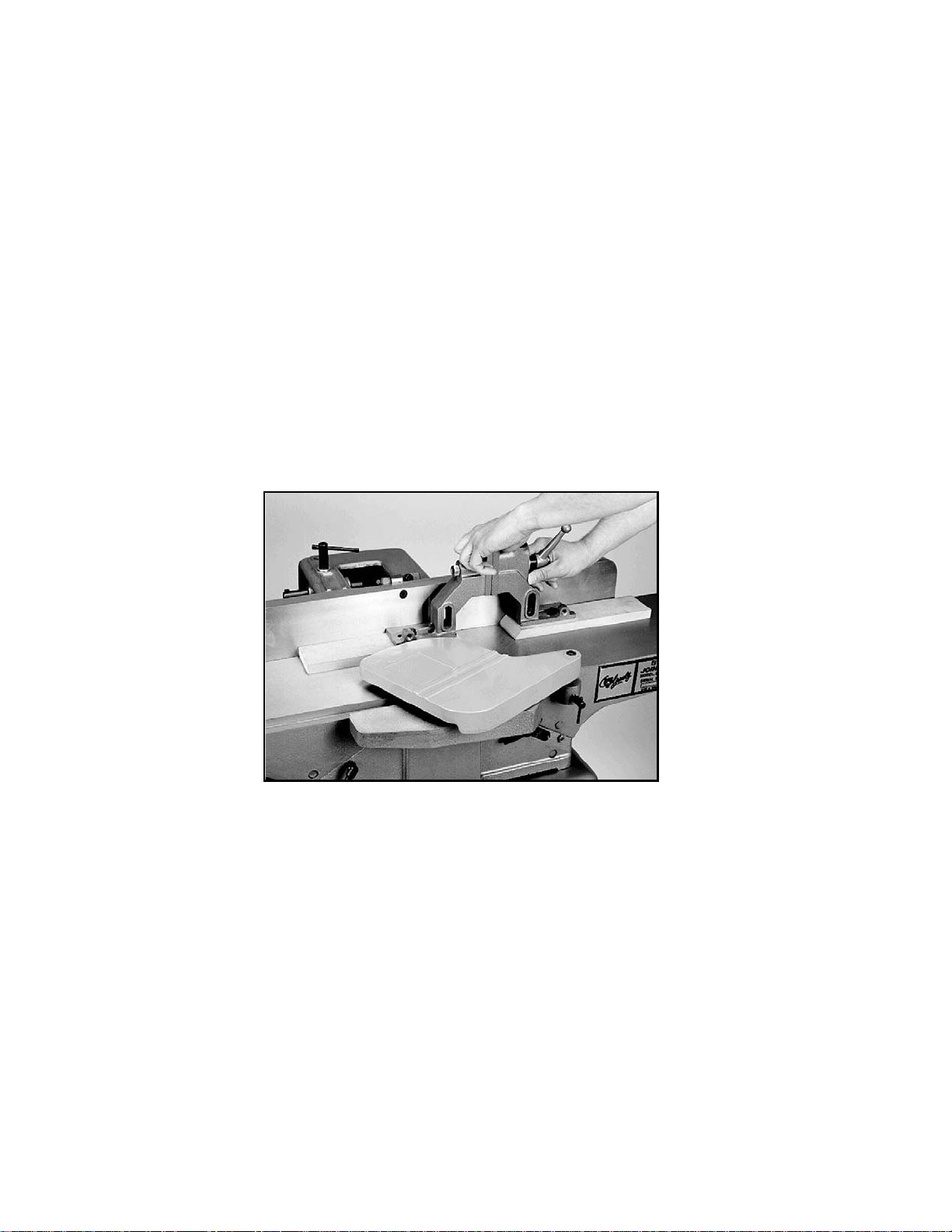
3. If the boards are not co-planar with each other, resurface the wooden fences as one unit. You
can perform this operation on a jointer. See Figure 6.
Figure 6
CAUTION: Make sure the bolt holes are countersunk deep enough so jointer knives will not come
in contact with the heads of the bolts. Check the jointer fence and bed for square. Run the shaper
fence through the jointer until both sides are co-planar. Check your work with your high-quality
straight edge. Remember: If the jointer is not set up properly, the results will be unsatisfactory. This
procedure can be continued as long as there is enough wood left for the jointer knives to clear the
bolt heads.
Once you are satisfied that the fence is co-planar, mount the fence assembly on the shaper table.
The mounting studs are already attached to the table. All you will need to do is remove the wing nuts,
place the fence assembly on the studs and re-tighten the nuts.
Page 13

C. SAFETY GUARD
The Model G1024 features a clear acrylic safety guard which is designed to deflect wood chips away
from the machine’s operator. To attach the guard, slip the support rod into the hole provided in the
bracket bolted to the back of the shaper table. See Figure 7. The height of the safety guard can be
adjusted by loosening the locking knob on the bracket and raising or lowering the support rod. Be
sure to re-tighten the locking knob securely after making height adjustments.
- 11 -
Figure 7
CAUTION: Always use some type of guard when operating your shaper. The cutter is spinning at
10,000 RPM – a knot or wood chip expelled from the shaper could cause severe injury to the operator if proper safety equipment is not in place.
In addition to a safety guard, always wear ANSI-approved eyewear and face shield to protect yourself while operating the shaper. Also avoid wearing loose fitting clothing and use a hat (to contain
long hair, if needed). Always follow the safety guidelines we’ve noted here in the manual. A few simple steps can avoid a world of heartache.
Page 14

X. SAFETY PROCEDURES
This tool is capable of causing serious injury if used recklessly. This doesn’t mean that the machinery should be feared, but it does deserve a healthy respect for its power and potential danger.
At the beginning of this manual we shared some general safety procedures with you. We want to reemphasize a few points we feel are critical to safe shaper operation:
1. GROUND EQUIPMENT PROPERLY. We can’t over-emphasize the importance of a well
grounded machine.
2. FOLLOW ELECTRICAL GUIDELINES. The electrical guidelines in this manual have been well
researched and represent safe and efficient standards for the operation of this tool.
3. DISCONNECT TOOL DURING MAINTENANCE. Any adjustments and/or maintenance should
be done with the power off, the plug pulled from the outlet and after all moving parts have come
to a complete stop.
4. AVOID FIRE DANGER. Wood waste is combustible and wood dust can be explosive. Smoking
and/or open fires should not be allowed in the work area.
5. MAINTAIN A CLEAN WORK AREA. Clean the machine and its surroundings thoroughly after
each use.
6. DON’T MIX WORK AND ALCOHOL. If you have taken any kind of medication which can impair
your responses, or if you have consumed any alcohol, DO NOT USE THIS MACHINE.
7. MAKE WORKSHOP CHILDPROOF. Use padlocks, master switches, or starter keys to prevent
children from injuring themselves on this, or any other machine.
8. KEEP HANDS AWAY FROM CUTTING KNIVES. A lot of people get hurt – sometimes seri-
ously, and always unnecessarily – by trying to pick out wood scraps from the surface of the
table while the machine is running. DO NOT attempt to clear anything away from the cutters
until the power is of, the shaper is unplugged and the cutter has come to a complete stop.
9. SHAPE PROPER MATERIALS. This shaper is designed to cut wood fibers only.
10. SECURE SHAPER TO THE FLOOR. The shaper should be permanently affixed to the floor.
Use the holes provided in the base.
11. READ THE MANUAL. Know the limitations and hazards of this shaper before attempting to use
it. If you don’t understand some aspect of this machine’s operation, DO NOT use it until you are
informed. Please call us for advice, if necessary.
12. SHORT STOCK. Never attempt to shape stock shorter than 12 inches in length without special
fixtures or jigs. Where practical, shape longer stock and cut to shape.
13. 12-INCH RULE. When using this shaper, never allow your hands to come within 12 inches of
the cutters.
- 12 -
Page 15
14. HAND SAFETY. Never pass your hands directly over, or in front of the cutter. As one hand
approaches the 12-inch radius point, move it away from the cutter to the outfeed side and reposition the hand at least 12 inches beyond the cutter.
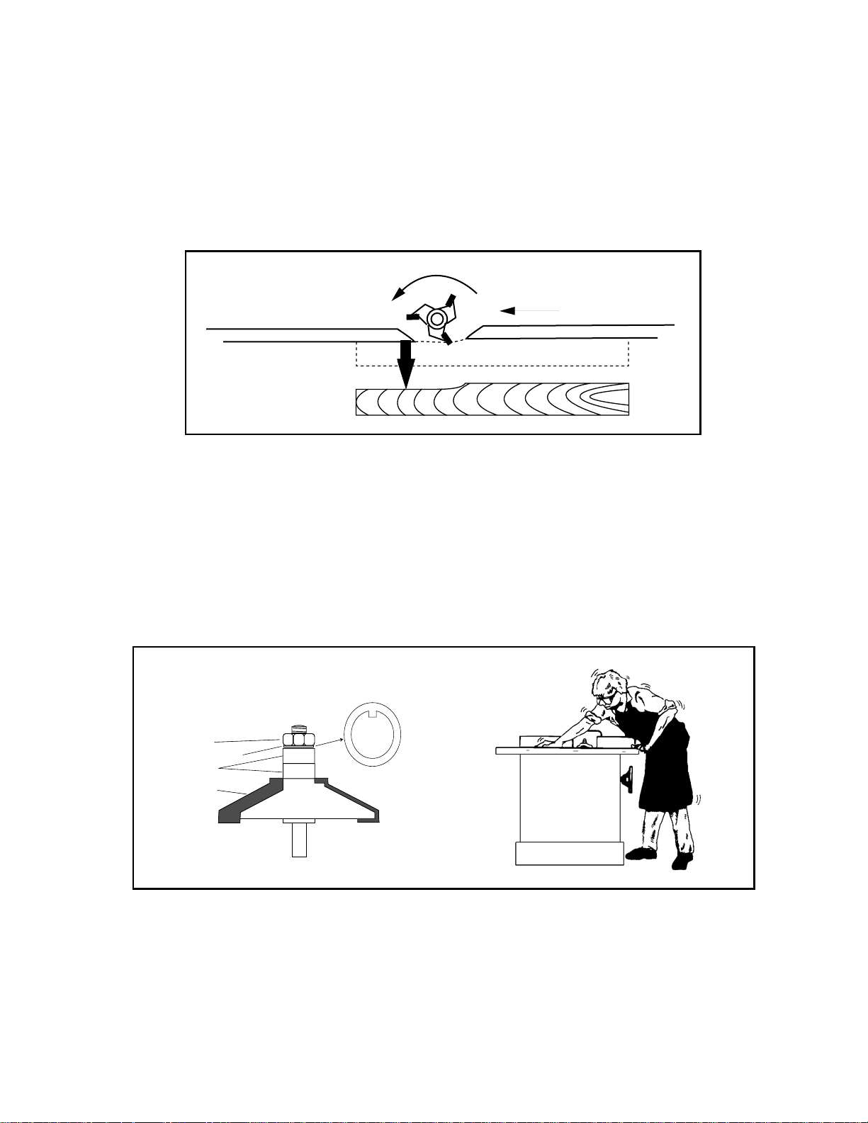
15. STOCK FEED. Always feed stock opposite the direction of the cutter rotation. For example, if
the cutter rotation is counterclockwise, feed from right to left. NEVER back stock out of the cutter along the fence, once the cut has been started. Instead, pull the stock straight back, away
from the fence and cutter and begin the cut again. See Figure 8.
16. BLIND CUT WHENEVER POSSIBLE. This keeps the knives on the underside of the workpiece
and provides a distance guard for the operator.
17. CUTTER CLEARANCE. With the machine unplugged, always rotate the spindle by hand with
any new setup to ensure proper cutter clearance before starting the machine.
18. SAFETY LOCK NUT. Never operate the Model G1026 Shaper without the second locking nut
in place over the spindle nut. See Figure 9.
FEED
C
U
T
T
E
R
Figure 8
HEX NUT
SPACERS
CUTTER
SAFETY WASHER
WRONG!
Figure 9
19. DO NOT REACH OVER THE SHAPER. There is a danger of kickback, which can pull your
hand into the cutter. Work from directly in front of the shaper, whenever possible.
- 13 -
Page 16

20. STOCK CONDITION. The danger of experiencing kick-back is increased when the stock has
knots, holes, or foreign objects in it. Warped stock should be run through a jointer before
attempting to run it through a shaper.
21. MISUSE. Do not use the Model G1024 for anything other than its intended purpose. If used for
other purposes, Grizzly disclaims any real or implied warranty and is not responsible for any
damage or injury which may result from that use.
22. USE the correct safety guards.
23. MAKE sure that fences, guides, or guards are mounted securely.
24. ALWAYS USE jigs, fixtures, or templates whenever possible.
25. KEEP ANY unused portion of the cutter below the table surface.
26. NEVER attempt to take too much material off in one pass.
27. WHEN SHAPING CONTOURED WORK and using a rub collar, NEVER start out at a corner.
See the rub collar section further on in the manual.
28. KEEP all cutting surfaces sharp.
29. BE SURE THE SPINDLE turns freely and all adjustment tools, etc., are off of the table before
the machine is turned on.
NOTE:Many manuals and books recommend the use of push sticks. While in some applications
they are useful safety devices, in others they can be quite dangerous. If the pushstick comes in contact with the cutter on the end grain, it can fly out of your hand like a bullet – potentially causing serious injury. We recommend using, instead, some type of fixture, jig, or hold-down device as a safer
alternative. This does not mean that we recommend using the machine without any safety protection. Use a guard, or other type of protective device at all times. Grizzly carries a number of protective devices for use with shapers. See the current catalog for details and ordering information.
30. THE SPINDLE must be adjusted correctly and locked in position before turning on the shaper.
31. AGAIN, IF THERE IS ANY ASPECT of this machine’s operation you do not understand, DO
NOT try to operate the shaper.
REMEMBER: ALWAYS WEAR PROTECTIVE EYEWEAR AND CLOTHING WHEN USING THIS,
OR ANY OTHER MACHINERY.
- 14 -
Page 17

XI. ADJUSTMENT SECTION
Any adjustments or maintenance performed on the Model G1024 should be done with the power off,
the plug disconnected from the power source and only after all moving parts have come to a complete stop. Make sure the machine is level and secure.
The following are recommended steps for adjusting the shaper. Please read the following adjustment procedures to ensure the shaper is adjusted and ready for operation.
This section covers adjustment procedures for the following items. Read and follow these directions
carefully.
A. Fence
B. Spindle
C. Spindle Elevation
D. Cutter Direction
A. FENCE
The Model G1024 Shaper’s fence uses a two-piece adjusting system. Each fence is adjustable to
compensate for different cutting thicknesses and special shaping applications, using the locking
knob at the rear of the shaper. See Figure 10. One turn of the knob moves the split fence approximately
3
/64" (.040"). When removing material from the whole face of your workpiece, the outfeed
fence should be adjusted to the proper offset to provide support for the workpiece as it passes over
the cutter. To adjust the fence:
1. Adjust the infeed fence so the cutter will remove the desired amount of stock.
2. Lock the infeed fence in position with the locking bolt.
3. Make a test sample and inspect the results.
4. Adjust the outfeed fence to support the new profiled edge. Lock the outfeed fence into position
and re-test. See Figure 11 and Figure 12 for improper and proper outfeed fence positioning.
- 15 -
Figure 10
Page 18

- 16 -
Outfeed Fence
Cutter Rotation
Workpiece
Infeed Fence
Feed Direction
Improper Fence Adjustment
Figure 11
When the shaping operation removes the entire face of the workpiece, the shaped surface will not
be supported by the outfeed fence when the fences are paralleled, or mis-aligned, as shown in
Figure 11. In this case, a test sample of the desired cut should be advanced to the point shown, then
stopped. Once the shaper is turned off and the cutter has come to a complete stop, the outfeed fence
can be re-adjusted to provide support for the milled surface of the workpiece. See Figure 12.
Outfeed Fence
Cutter Rotation Infeed Fence
Workpiece
Feed Direction
Proper Fence Adjustment
Figure 12
When performing work which requires that both fences be in-line – such as a cut where only a portion of the workpiece’s surface comes in contact with the cutter – you should begin by adjusting the
infeed fence to the point where only the desired amount of the workpiece comes in contact with the
knives. Use a test piece to determine your ideal setting. Once your positioning is correct, lock the
infeed fence in place.
Once you adjust the infeed fence to your liking, adjust the outfeed fence to the same plane as the
infeed. Use a high-quality straight edge to ensure parallelism. Lock the outfeed fence in place. Once
again, run a test piece through the shaper to check your results. See Figure 13. Remember to unplug
your shaper while making fence adjustments.
Page 19

- 17 -
C
U
T
T
E
R
Feed Direction
Workpiece
Cutter Rotation
Outfeed Fence
Infeed Fence
Figure 13
Take your time when adjusting the fence. Always use a piece of scrap wood to make a first run sample. Micro-adjust accordingly. Double check yourself to make sure all hold-down devices are secure.
Remember to use appropriate guards when using the fence system.
B. SPINDLE
The standard 1/2" spindle on your Model G1024 Shaper is capable of using most available 1/2" cutters with maximum diameters of 2
7
/8" and 23/8" maximum height. To install a cutter on your shaper:
1. Remove the spindle nut and safety washer from the spindle shaft. Some Model G1024 Shapers
may feature a lock nut instead of a safety washer.
2. Select the proper shaper cutter for the application you desire and place it on the spindle. Make
sure the cutter’s direction of rotation is correct for your application.
3. Once the cutter is properly seated on the spindle shaft, replace the safety washer, making sure
that it aligns properly with the notch in the spindle shaft.
4. Return the spindle nut to its position on the spindle shaft and tighten it. Use an appropriate
wrench on the squared head of the spindle shaft to hold the shaft in place while you tighten the
spindle nut. See Figure 14. If your shaper features a lock nut, tighten it over the spindle nut.
Figure 14
Page 20

C. SPINDLE ELEVATION
The Model G1024 Shaper features a locking spindle which can be adjusted for up to 7/8" of vertical
movement. To adjust the height of the spindle:
1. Loosen the locking knob on the right-hand side of the shaper.
2. Reaching under the shaper table, move the vertical adjustment lever right or left until the spindle reaches its desired height. See Figure 15.
3. Re-tighten the locking knob.
4. Run a test piece through the shaper to verify that the spindle is set at the desired height and readjust as necessary.
- 18 -
Figure 15
REMEMBER: Always make sure that the shaper’s power switch is in in the “OFF” position and that
the machine is disconnected from its power source before attempting to make adjustments to the
machine or the shaper cutter. Never attempt to adjust the machine while the cutters are spinning.
E. CUTTER DIRECTION
Your shaper is equipped with a toggle FORWARD/REVERSE switch, located at the rear of the
shaper. See Figure 16. Many shaper cutters are manufactured for both clockwise and counterclockwise rotation, allowing you to cut above or below the board. Whenever possible, attach the cutter so the board is milled on the bottom side. This does a better job and it is safer for the operator.
CAUTION: Always check the direction of cutter rotation before any shaping operation. While many
cutters are designed to be used in both directions, some are not. Make sure that the cutter you’re
using is intended for use in both directions before attempting to reverse it. Whenever using your
shaper, make sure that your workpiece is fed against the direction of the cutter rotation. A workpiece
fed into a cutter from the wrong direction may be thrown by the cutter, possibly causing injury to the
user or any bystanders.
Figure 16
Page 21

- 21 -
XII. RUB COLLARS
Rub collars are used when shaping curved or irregular workpieces, such as arched doors or round
table tops. They also allow you to perform freehand work.
There are two types of rub collars; solid and ball-bearing. Don’t confuse spacers with solid rub collars. Spacers aren’t always machined to close tolerances and not every ball-bearing can be used as
a rub collar. Grizzly carries an extensive line of spacers and rub collars designed for use with Grizzly
shapers. See the current catalog for listings.
IMPORTANT: The diagrams shown on the following pages denote different methods and arrange-
ments for spindle stacking. These diagrams are intended as a source of general reference.
Remember to apply all of the safety considerations we have covered to this point, as well as those
to come – as they apply to your situation. If you are confused about any of the configurations, DO
NOT attempt them. Seek adequate instruction before attempting complex shaper operations.
NOTE: the following illustrations are shown with the guard removed for clarity. DO NOT attempt to
operate the shaper without guards or protective devices in place.
A. HOW RUB COLLARS ARE USED
Collars are used to limit the depth of your cuts and are particularly useful when doing pattern work
or irregular shaping. The amount of wood to be removed from the workpiece is determined by the
diameter of the rub collar and the cutting circle of the cutter. Some hints for the selection of rub collars are listed below. PLEASE FOLLOW THE SAFETY MEASURES WE HAVE NOTED THROUGHOUT THE MANUAL.
1. Select the appropriate shaper cutter to match your desired profile.
2. Determine if you will be working with a pattern or if the workpiece will rub against the collar.
3. Determine how much wood must be removed to achieve the desired profile.
When only part of an edge is to be milled, as in Figures 17-19, the workpiece will guide itself along
the collar. If that is the case with your operation, you’ll want to select a rub collar that will allow just
the desired amount of wood to be removed. When shaping with a pattern, the shape and size of the
pattern will limit the amount of wood removed from the workpiece. The pattern gives you the option
of selecting the number of rub collars that best suits your application...depending on the size of the
pattern.
Page 22
B. EXAMPLES
Rub collars may be used in any of the following positions:
1. Below the cutter.
2. Above the cutter.
3. Between two cutters.
Suppose you want to mill a
3
/8" x 1/2" rabbet. You must have a sufficient amount of uncut wood to
provide adequate contact with the rub collar. Remember that the width of the rabbet is controlled by
the diameter of the rub collar and the depth of the rabbet is controlled by the spindle height adjustment. A rabbet cut is a good example, since you’ll get the same result with the rub collars either
above or below the cutter. The following diagrams illustrate different spindle configurations.
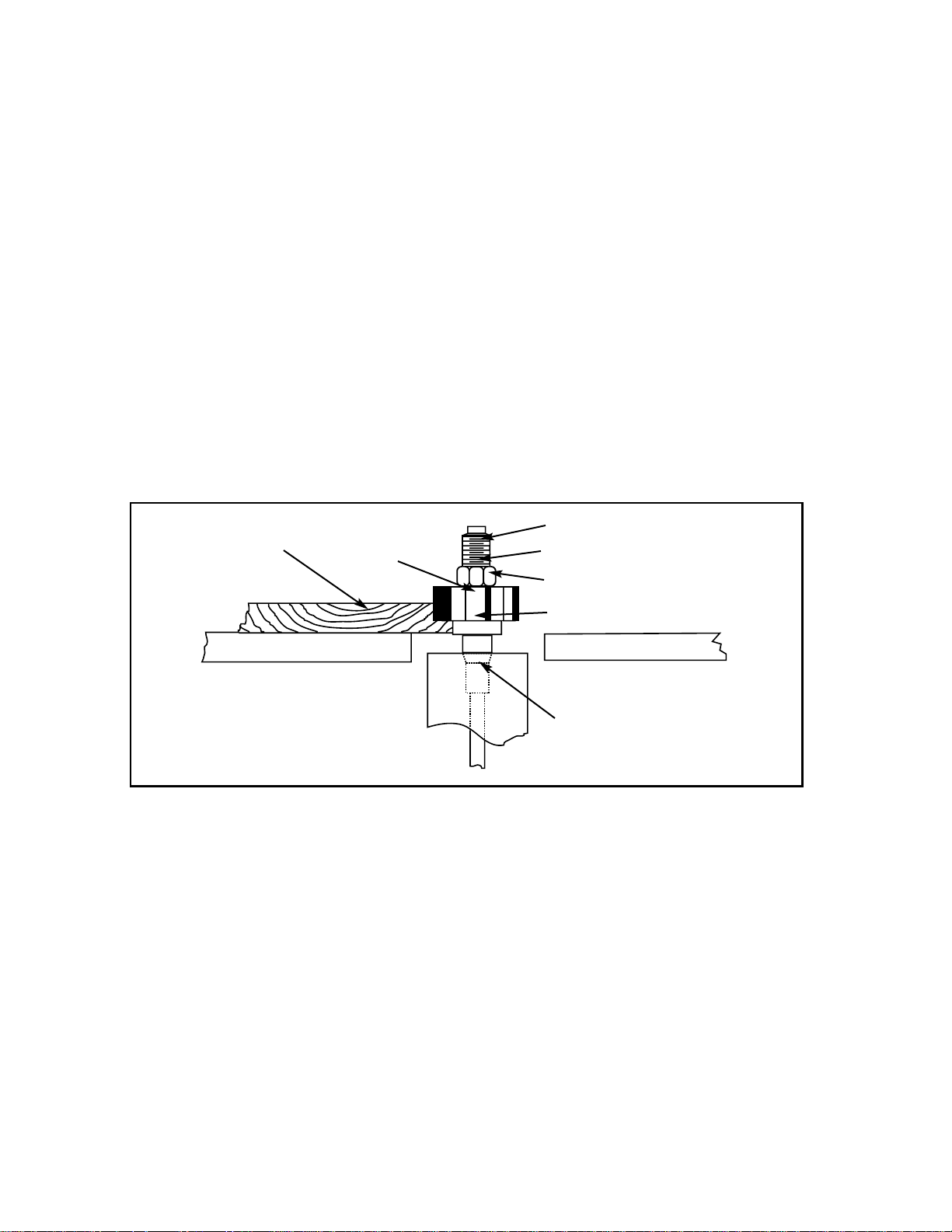
Workpiece
Spindle
Spindle Nut
Cutter
Rub Collar
Table
Table
Spindle Assembly
Figure 17
When the rub collar is used below the cutter, as shown in Figure 17, the progress of the cut can be
observed. However, any unintentional movement may lift the workpiece into the cutter, damaging
your work and creating an unsafe situation.
Rub collar below the cutter:
- 20 -
Safety Washer
Page 23

Spindle Assembly
Table
Table
Rub Collar
Spindle Nut
Workpiece
Cutter
Figure 18
When the collar is used above the cutter, as shown in Figure 18, the cut cannot be seen. Yet, this
offers some advantage in that the cut is not affected by slight variations in the stock. Also, accidental
lifting will not damage the workpiece. Simply correct the mistake by repeating the operation. The
stacking arrangement is considerably safer because the workpiece covers the entire shaper cutter.
Rub collar above the cutter:
Spindle
- 21 -
Figure 19
Table
Cutter
Workpiece
Spindle Nut
Rub Collar
Cutter
Table
Spindle Assembly
Rub collar between two cutters:
Spindle
Using a rub collar between two cutters has the distinct advantage of performing two cuts at once or
eliminating the need to change cutters for two different operations. See Figure 19. Notice that part
of the edge is left uncut. The uncut portion rides on the rub collar. Remember to leave a sufficient
amount of wood to offer a safe bearing surface.
Safety Washer
Safety Washer
Page 24

C. PATTERN WORK
When using a pattern, the rub collar can be positioned either above, below, or in-between cutters.
See Figure 20.
The pattern is usually used when the entire edge is to be shaped or when many duplicate pieces are
needed. Pattern work is particularly useful when rough cutting irregular shapes oversize and then
shaping the edge in a simple two-step operation. A pattern can be incorporated into a fixture by way
of adding toggle clamps, hand holds, or other safety devices.
Spindle Assembly
Table
Table
Spindle Nuts
Rub Collar
Cutter
Workpiece
Pattern
Figure 20
- 22 -
Spindle
You have greater flexibility when choosing the correct diameter rub collar for pattern work than for
non-pattern work. If you look at Figure 20, you’ll notice that the position of the pattern determines the
depth of cut. In other words, your pattern size is dependent upon the inter-relationship of cutting circle, the desired amount of material removed and the rub collar size. The cutting circle is the given
in the equation, while the pattern and the rub collar size are the variables. Changing one or both of
these will change the amount of material removed. Planning ahead, you can best decide which rub
collars are best suited for your application.
XIII. SHAPING
A. STRAIGHT STOCK
When shaping straight stock, use the fence assembly. See the fence adjustment section for information on aligning fences.
1. Select the appropriate cutter and lock onto the spindle.
2. Check cutter rotation.
3. Adjust the spindle height to align the workpiece to the cutter. See the spindle height section for
details.
4. Lock the spindle into position.
Safety Washer
Page 25

5. Position the fences for your desired depth of cut. See the fence adjustment section for details.
6. Use a hold-down, or other safety device. See Figures 21 and 22.
7. Make a sample cut on a scrap piece of wood to check your adjustments.
8. If everything is correct, run your stock through the shaper using your left hand to support the
workpiece against the fence and your right to feed (if the rotation is counterclockwise). Switch
hands for clockwise rotation.
9. Use the miter gauge to shape the ends of your workpiece.
Figure 21
- 23 -
Figure 22
NOTE: Safety devices, as shown here, substantially improve the quality and consistency of your
work, as well as ensuring operator safety. Grizzly offers a number of excellent safety devices for use
with shapers – such as the Board Buddies™ shown below – which are available as optional equipment on the Model G1024 Shaper. For more information and pricing details, see the latest Grizzly
catalog.
Page 26

B. IRREGULAR SHAPING
Irregular or freehand shaping takes a high degree of skill and dexterity. This is where the real application of the shaper comes into focus. The fence assembly is not used in irregular shaping, so rub
collars must be used. Choose the correct diameter for the appropriate depth of cut. See the rub collar section for details.
CAUTION: Freehand work is one of the most dangerous operations done on a shaper.
When doing freehand work a starting pin must be used. The purpose of the starting pin is to support
the workpiece during the beginning of the cut.
1. Your shaper is supplied with a starting pin which is placed in one of the holes located in the
shaper table. See the Main Body Diagram for location.
2. The work should be placed in the starting position using the guide pin for support, as shown in
Figure 23. Next, swing the work into the cutter while holding the workpiece firmly against the
starting pin.
3. After the cut has been started, the work is swung away from the starting pin and is supported
just by the collar, as shown by the broken line positions in Figure 23. ALWAYS FEED AGAINST
THE ROTATION OF THE CUTTER.
Figure 23
- 24 -
Important: Always use a starting pin or pivot support for freehand work.
For irregular shaping:
1. Remove the fence assembly.
2. Choose the appropriate cutter for your application and lock it in place.
3. Check cutter rotation.
4. Adjust the spindle height to align your workpiece to the cutter.
STARTING PIN
ROTATION
WORKPIECE
FEED
SWING
Page 27

5. Insert a starting pin into the table surface, using the pin location that best supports your work.
6. Inspect your stock or pattern for any irregularities that might transfer to the cut.
7. Use some type of hold-down fixture and guard when doing freehand work. See Figure 24.
Figure 24
8. Make a sample cut on a piece of scrap wood.
9. If everything is correct, feed your workpiece along the cutter, using firm pressure to keep your
work against the rub collar. Feed against the cutter rotation only.
- 25 -
Notice in Figure 24, the operator is not exposed to the cutting edge of the cutter. Cutters are removing material from the bottom of the workpiece.
Sometimes the starting pin will not be in the most advantageous position. Using a board firmly
clamped to the shaper table, as shown in Figure 24, will give you the same support as the starting
pin, with a better starting position. Always use a starting support when doing freehand work.
When using a solid rub collar, do not use excessive pressure when running your workpiece through
the shaper. Otherwise, a groove may burn into your pattern and be transferred to your workpiece.
Instead, take several passes, using lighter pressure against the rub collar. If you find this to be a consistent problem, you may consider using ball bearing rub collars instead of solid collars.
Page 28
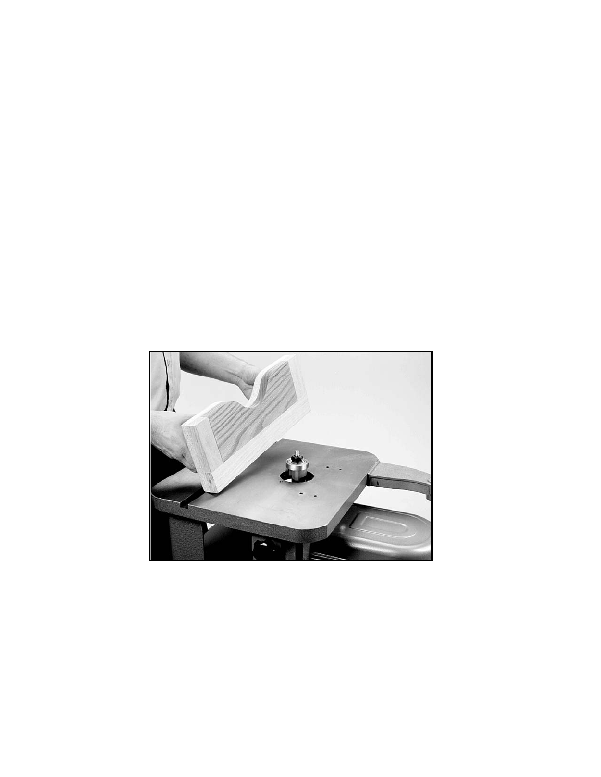
Figure 25
When making a pattern, jig, or fixture, here are a few things to consider:
1. Use a material that will smoothly follow the rub collar or fence.
2. Make the fixture stable. Use proven methods and materials.
3. Fasten hand holds for operator comfort and safety.
4. Secure your workpiece on three sides with toggle clamps or fasten the workpiece to the fixture
with wood screws. Make sure they do not protrude through the workpiece.
5. Ensure that clamps and hidden screws do not come into contact with the cutter.
6. Design your fixture so that all cutting occurs underneath the workpiece.
7. Always consider cutting circle and rub collar diameter for correct depth of cut when designing
your pattern.
8. Make sure the workpiece rests flat on the table, not on the fixture.
9. Remember, there is tremendous cutting force on the workpiece. Fixtures must be solid, stable
and the workpiece must be firmly secured. See Figure 25.
- 26 -
Page 29

XIV. EQUIPMENT MAINTENANCE
Your Model G1024 Shaper requires very little maintenance. A thorough cleaning, now and again, will
increase the machine’s durability and efficiency, by removing dust and grime that can gum up moving parts. Sharp cutting surfaces are essential for top performance. If you find that the machine cuts
less efficiently than usual, inspect the cutters and repair or replace them as necessary. An occasional application of Top-Cote
®
protective spray will keep the shaper table and other bare metal parts
from rusting and pitting. Remember: When performing maintenance or repairs on this, or other shop
equipment, always disconnect the power supply.
A. LUBRICATION
The Model G1024 features factory-sealed bearings. A sealed bearing requires no lubrication during
its lifetime.
Should a bearing fail, your shaper will probably develop a noticeable rumble, which will increase
when the machine is put under load. If allowed to get worse, overheating of the journal containing
the bad bearing could occur. If the bad bearing is not replaced, it will eventually seize – possibly
doing damage to other parts of the machine. Bearings are standard sizes and can be replaced
through Grizzly.
The only parts on this machine that require periodic lubrication are the ways where the cartridge
slide rides on the elevation housing and where the worm gear and bushing are located. Use a light
grease or anti-seizing compound on the ways and worm gear and give the shaft mount a shot of light
oil. The frequency of lubrication depends on the amount you use the shaper. As a habit, inspect the
machine at least one a month.
B. V-BELT MAINTENANCE
Avoid getting grease or oil on the V-belt or pulleys.
Check the V-belt, as part of your monthly inspection, for proper tension and belt condition. Cracking
and glazing could result in belt failure. Replace the belt if such conditions appear.
XV. CLOSURE
The following pages contain the directory of parts for your Model G1024 Shaper. We have also
included a wiring diagram and instructions for using the optional Router Bit Spindle for your convenience.
Please feel free to write or call us if you have any questions about the machine or the manual.
Thank you again for your business and continued support. We hope to serve you again soon.
- 27 -
Page 30

XVI. MACHINE DATA
GRIZZLY MODEL G1024 3/4 H.P. SHAPER
Design Type ....................................................................................................................Floor Model
Overall Dimensions:
Table ................................................................................................................................15” x 18”
Height From Floor to Top of Fence ..........................................................................................38"
Height to Table From Floor ....................................................................................................34
1
/2"
Length........................................................................................................................................24"
Width ........................................................................................................................................27"
Weight (Shipping) ..............................................................................................................155 lbs.
Weight (In Place) ..............................................................................................................145 lbs.
Construction:
Table ..................................................................................................................Ground Cast Iron
Fence Assembly ..............................................................................................................Cast Iron
Body Assembly ................................................................................................................Cast Iron
Stand....................................................................................................................Pre-formed Steel
Specifications:
Spindle Travel ..........................................................................................................................3
7
/8"
Spindle Diameter........................................................................................................................
1
/2"
Spindle Length ............................................................................................................................3"
Spindle Capacity under Nuts ..................................................................................................2
3
/8"
Spindle Speed ............................................................................................................10,000 RPM
Table Counterbore ......................................................................................3" Diameter,
3
/8" Deep
Spindle Bearings ................................................................Ball/Shielded and Lubricated-For-Life
Motor:
Type..............................................................................................TEFC Capacitor Start Induction
Horsepower ........................................................................................................................
3
/4 H.P.
Phase / Cycle ..............................................................................................Single Phase / 60 HZ
Voltage ..........................................................................................................................110V/220V
Amps........................................................................................................................................10/5
RPM ........................................................................................................................................3450
Bearings..................................................................................
Shielded and Lubricated-For-Life / Ball
Features:
Fence ..........................................................................................................Both Sides Adjustable
Switch ..............................................................................................................................ON/OFF
Switch ............................................................................................................................Reversible
Starting Pins ....................................................................................................................Standard
Protective Cover For Freehand Work..............................................................................Standard
Spindle Lock ....................................................................................................................Standard
Miter Gauge ....................................................................................................................Standard
Specifications, while deemed accurate, are not guaranteed.
- 28 -
Page 31

XVII. WARRANTY AND RETURNS
LIMITED WARRANTY
Grizzly Industrial, Inc. warrants every product it sells for a period of one year on all parts and one
year on all electric motors to the original purchaser from the date of purchase. This warranty does
not apply to defects due directly or indirectly to misuse, abuse, negligence, accidents, repairs or
alterations or lack of maintenance. This is Grizzly’s sole written warranty for any and all warranties
that may be implied by law, including any merchantability or fitness, for any particular purpose, are
hereby limited to the duration of this written warranty. We do not warrant or represent that the merchandise complies with the provisions of any law or acts unless the manufacturer so warrants. In no
event shall Grizzly’s liability under this warranty exceed the purchase price paid for the product and
any legal actions brought against Grizzly shall be tried in the State of Washington, County of
Whatcom.
We shall in no event be liable for death, injuries to persons or property or for incidental, contingent,
special, or consequential damages arising from the use of our products.
To take advantage of this warranty, the product or part must be returned to either our Bellingham or
Williamsport warehouse, freight pre-paid. Proof of purchase must accompany the merchandise. The
manufacturers reserve the right to change specifications at any time as they continually strive to
achieve better quality equipment.
We make every effort to ensure that our products meet high quality and durability standards and we
hope you never need to use this warranty.
- 29 -
Page 32
- 32 -
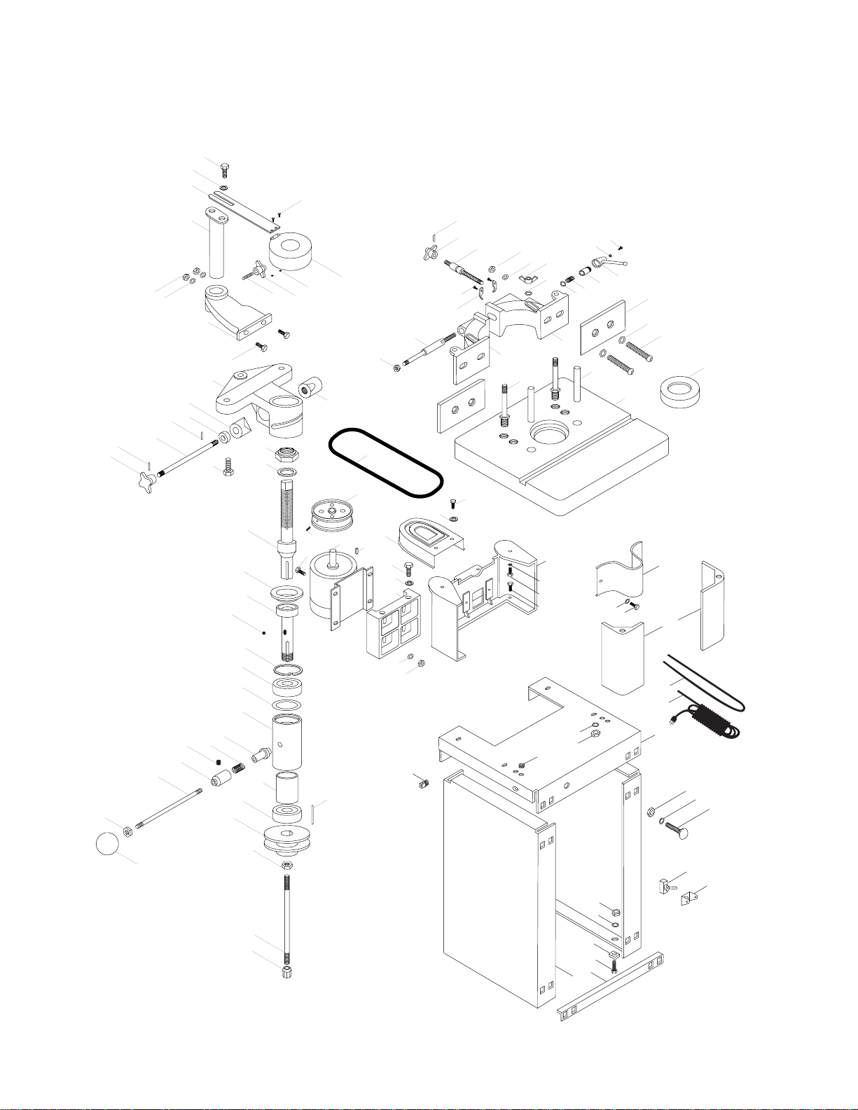
XVIII. PARTS LISTS AND DIAGRAMS
A. MAIN BODY ASSEMBLY
72
73
53
70
59
60
52
71
68
69
62
58
50
65
66
51
74
75
56
57
63
63-1
67
64
49
97
48
42
43
46
45
44
35
34 29
28
47
27
30
36
40
37
26
38
41
39
31
32
33
25
24
88
89
87
86
85
84
83
79
92
77
78
80
81
111
82
91
76
94
95
96
90
101
99
93
100
98
112
23
106
105
104
102
103
113
21
22
14
19
20
13
114
12
11
15
16
17
6
5
4
3
2
1
109
110
10
18
8
107
7
9
108
Page 33

- 33 -
001 P1022003 Side Panel
002 P1024002 Tie Bar
003 PB02M Hex Bolt M6-1.0x12
004 P1024004 Rubber Foot
005 PW02 Flat Washer
3
/8"
006 PN01M Hex Nut M6-1.0
007 PW02 Flat Washer
3
/8"
008 PN03M Hex Nut M8-1.25
009 PCB01M Carriage Bolt M8-1.25x20
010 P1024010 Shelf
011 PN03M Hex Nut M8-1.25
012 PW02 Flat Washer
3
/8"
013 PB06M Hex Bolt M8-1.25x12
014 P1024014 Table Support
015 P1024015 Spindle Pulley Guard
016 PW02 Flat Washer
3
/8"
017 PB03M Hex Bolt M8-1.25x16
018 P1024018 Table Leg
019 PW01 Flat Washer
1
/2"
020 PB25M Hex Bolt M12-1.75x25
021 PW02 Flat Washer
3
/8"
022 PB06M Hex Bolt M8-1.25x12
023 P1024023 Belt Guard
024 P1024024 Working Table
025 P1024025 Table Insert
026 P1024026 Taper Pin
027 P1024027 Clamp Stud
028 PW07 Flat Washer
5
/16"
029 PWN03 Wing Nut
5
/16"-18
030 P1024030 Fence Body Right
031 P1024031 Wooden Fence
032 PW06 Flat Washer
1
/4"
033 P1024033 Slot Head Screw
034 PW07 Flat Washer
5
/16"
035 PN03M Hex Nut M8-1.25
036 PW01 Flat Washer
1
/2"
037 P1024037 Coil Spring
038 P1024038 Spring Collar
039 P1024039 Lock Handle
040 PW06 Flat Washer
1
/4"
041 PS14M Phil Hd Screw M6-1.0x12
042 P1024042 Half Collar
043 PSB26M Cap Screw M6-1.0x12
044 P1024044 Adjusting Screw Stud
045 P1024045 Hand Knob
046 PRP16M Roll Pin 3x25
047 P1024047 Fence Body Left
048 P1024048 Clamp Stud
049 PN09M Hex Nut M12-1.75
050 P1024050 Mounting Bracket
051 PB26M Hex Bolt M8-1.25x30
052 PW02 Flat Washer
3
/8"
053 PN03M Hex Nut M8-1.25
056 P1024056 Stud Bolt
057 P1024045 Hand Knob
058 P1024058 Hex Post
059 PB06M Hex Bolt M8-1.25x12
060 PW02 Flat Washer
3
/8"
062 P1024062 Hold Down Bar
063 PS02M Phil Hd Screw M4-0.7x12
63-1 PN04M Hex Nut M4-0.7
064 P1024064 See Through Ring Guard
065 P1024065 Spindle Housing Bracket
066 PB27M Hex Bolt M12-1.75x30
067 P1024067 Clamp Sleeve Right
068 P1024068 Clamp Sleeve Left
069 P1024069 Stuff Ring
070 P1024070 Lock Bar
071 PRP02M Roll Pin 3x16
072 P1024045 Hand Knob
073 PRP02M Roll Pin 3x16
074 P1026219 Spindle Nut
Ref. # Part # Description Ref. # Part # Description
B. MODEL G1024 SHAPER PARTS LIST
Page 34

- 34 -
075 P1026223 Safety Washer
076 P1024076 Cutter Spindle
077 P1024077 Bearing Cover
078 P1024078 Spindle Cartridge
079 P1024079 Steel Ball
080 PR23M Retaining Ring 40mm
081 P6203 Ball Bearing
082 P1024082 Spindle Housing
083 P1024083 Bearing Cone
084 P1024084 Coil Spring
085 PSS20M Setscrew M8-1.25x8
086 P1024086 Spring Collar
087 P1024087 Stud
088 PN09M Hex Nut M12-1.75
089 P1024089 Knob
090 P1024090 Collar
091 P6203 Ball Bearing
092 P1024092 Spindle Pulley
093 PRP13M Roll Pin 3x25
094 P1022124 Hex Nut 17mm
095 P1024095 Tie Rod
096 P1024096 Tie Rod Nut
097 PVA30 V-belt A-30
098 P1024098 Motor Pulley
099 PSS04M Setscrew M6-1.0x12
100 P1024100 Motor
101 P1024101 Carriage Bolt
102 PW02 Flat Washer
3
/8"
103 PN03M Hex Nut M8-1.25
104 P1024104 Motor Mount Plate
105 PW01 Flat Washer
1
/2"
106 PSB26M Cap Screw M6-1.0x12
107 PSW05 Forward/Reverse Switch
108 P1024108 Switch Bracket
109 P1024109 Wire Cord
110 P1024110 Wire Cord
111 P1024111 Wavy Washer
112 PK01M Key 5x5x22
113 P1024113 Strain Relief
114 P1024113 Strain Relief
115 P1024115 Reversing Switch
Ref. # Part # Description Ref. # Part # Description
B. MODEL G1024 SHAPER PARTS LIST (CONTINUED)
Page 35

XIX. USING THE MODEL G1793 ROUTER BIT SPINDLE
- 35 -
The Model G1793 Router Bit Spindle is a handy accessory available for your Model G1024 shaper,
which allows you to use your standard router bits as shaper cutters.
Using the optional router bit spindle does require some minor modifications to the Model G1024.
To maximize the effectiveness of the router spindle, it is necessary to build a false table to increase
the height of the shaper table by 1
1
/2". To make a false table:
1. Cut two sheets of
3
/4" hardwood plywood or MDF-grade particle board slightly larger than the
size of your shaper table’s surface. Face glue the two pieces together. After the glue has
dried, you can either cut the pieces down to the exact size of the shaper table, or let them
extend beyond its edges.
2. To create a smooth working surface, attach a plastic laminate, such as Formica or Wilsonart,
to the top of your false table.
3. Disconnect your shaper from its power source and tape a sheet of tracing paper to the
shaper’s table. Be sure to align the back edge of the tracing paper with the back edge of the
machine to use as a reference guide on the false table.
4. Locate the four fence mounting holes and the opening for the spindle by rubbing a pencil over
those areas. Do this for the starting holes as well. Transfer all of your marks to the false table.
5. Drill the four fence mounting holes and the two starting pin holes with an 11/32" drill bit. Cut the
spindle opening with a hole saw or saber saw.
6. If you intend to use your miter gauge with your router spindle installed, cut a straight slot
3
/4"
x
3
/8
" parallel to the existing miter slot.
7. Mount your false table to the shaper’s table top, using two 8mm-1.25 x 150mm fence bolts.
NOTE: If most of your work calls for edge forming bits (roundover, cove, chamfer and so on), a
1
1
/2" table should be sufficient. On the other hand, if you desire to use more complicated bits, you
might want to add a third layer to the false table, bringing it up to 2
1
/4". If you choose to include that
extra level of height, remember to make suitable adjustments to the height of both the fence bolts
and the starting pins.
CAUTION: The Router Bit Spindle is made for one-direction operation. Reversing the direction of
the cutter travel could result in the loosening of the collet, making it possible for the bit to loosen
and unexpectedly exit the spindle.
 Loading...