

Page 1

KNIFE BELT SANDER/BUFFER
MODEL G1015
INSTRUCTION MANUAL
COPYRIGHT © 1999 BY GRIZZLY INDUSTRIAL, INC.
WARNING: NO PORTION OF THIS MANUAL MAY BE REPRODUCED IN ANY SHAPE
OR FORM WITHOUT THE WRITTEN APPROVAL OF GRIZZLY INDUSTRIAL, INC.
REVISED OCTOBER,1999. PRINTED IN U.S.A.
Page 2

G1015 Knife Belt Sander/Buffer -2-
Table Of Contents
PAGE
1. SAFETY
SAFETY RULES FOR ALL TOOLS ......................................................................3-4
ADDITIONAL SAFETY INSTRUCTIONS FOR SANDERS ......................................5
2. CIRCUIT REQUIREMENTS
110V OPERATION ....................................................................................................6
FUSING ....................................................................................................................6
EXTENSION CORDS ................................................................................................6
GROUNDING ............................................................................................................6
3. INTRODUCTION
COMMENTARY ........................................................................................................7
UNPACKING..............................................................................................................8
PARTS INVENTORY ................................................................................................8
CLEAN UP ................................................................................................................9
SITE CONSIDERATIONS ........................................................................................9
4. ASSEMBLY
MOUNTING BASE ..................................................................................................10
MOTOR....................................................................................................................11
PIVOT ARM........................................................................................................11-12
DRIVE WHEEL ........................................................................................................12
UPPER ARM ASSEMBLY ......................................................................................13
SANDING BELT SHOE ..........................................................................................13
BELT INSTALLATION ............................................................................................14
TOOL REST ............................................................................................................14
5. ADJUSTMENTS
BELT TENSION ......................................................................................................15
TOOL REST ............................................................................................................15
BELT TRACKING ....................................................................................................16
6. OPERATIONS
TEST RUN ..............................................................................................................17
BELT SANDING ................................................................................................17-18
BUFFING AND POLISHING....................................................................................19
DRUM SANDING....................................................................................................20
ACCESSORY REMOVAL........................................................................................20
7. MAINTENANCE
GENERAL................................................................................................................21
LUBRICATION ........................................................................................................21
BELTS AND DRUMS ..............................................................................................21
8. CLOSURE ....................................................................................................................22
TROUBLESHOOTING ........................................................................................................23-24
WARRANTY AND RETURNS..................................................................................................25
Page 3
-3- G1015 Knife Belt Sander/Buffer
Safety Instructions For Power Tools
SECTION 1: SAFETY
5. KEEP CHILDREN AND VISITORS
AWAY. All children and visitors should be
kept a safe distance from work area.
6. MAKE WORK SHOP CHILD PROOF with
padlocks, master switches, or by removing
starter keys.
7. DON’T FORCE TOOL. It will do the job
better and safer at the rate for which it was
designed.
8. USE RIGHT TOOL. Don’t force tool or
attachment to do a job for which it was not
designed.
1. KEEP GUARDS IN PLACE and in working
order.
2. REMOVE ADJUSTING KEYS AND
WRENCHES. Form habit of checking to
see that keys and adjusting wrenches are
removed from tool before turning on.
3. KEEP WORK AREA CLEAN. Cluttered
areas and benches invite accidents.
4. DON’T USE IN DANGEROUS ENVIRONMENT. Don’t use power tools in damp or
wet locations, or where any flammable or
noxious fumes may exist. Keep work area
well lighted.
For Your Own Safety Read Instruction
Manual Before Operating This Equipment
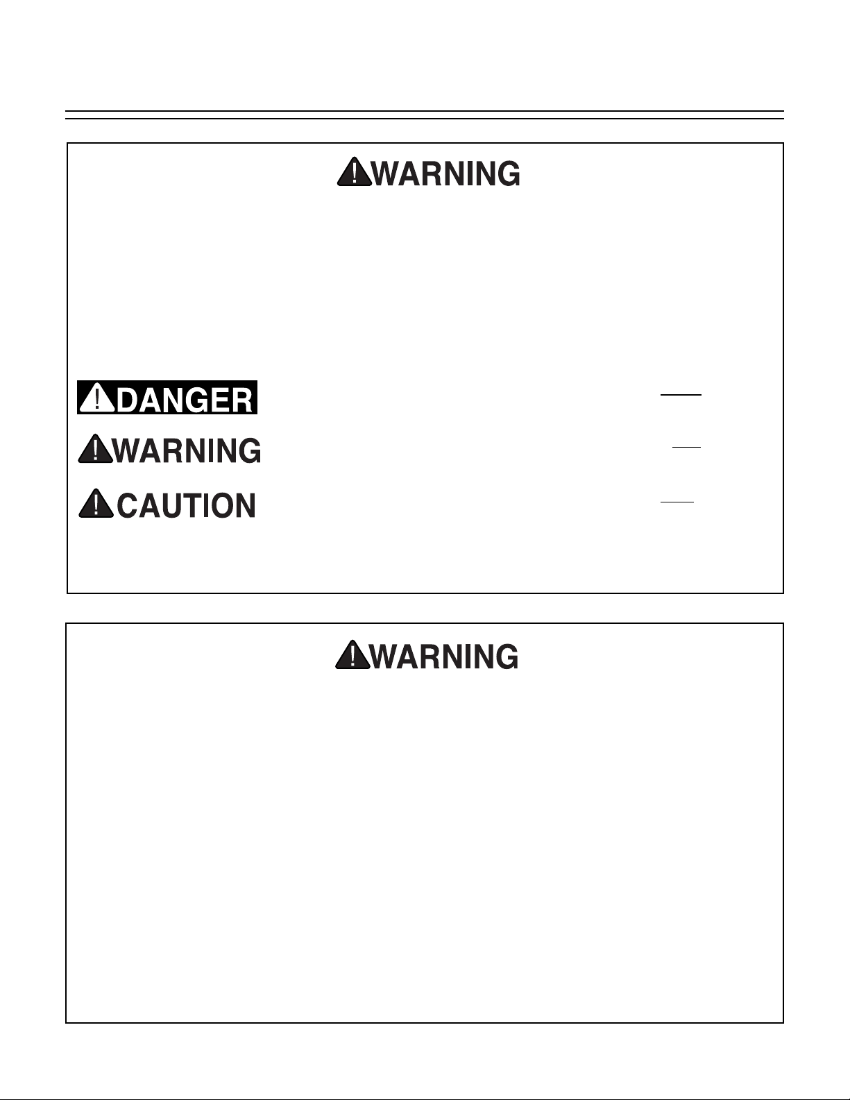
Failure to obey a DANGER symbol and notation WILL result
in serious personal injury including loss of life or body parts.
Failure to obey a WARNING symbol and notation can
result
in serious injury to yourself and others.
Failure to obey a CAUTION symbol and notation may result in
minor or moderate property damage or personal injury.
This symbol is used to alert the user to useful information about
proper operation of the equipment.
The purpose of safety symbols is to attract your attention to possible dangers. This manual uses
a series of symbols which are intended to convey the level of criticality of the safety message.
The progression of symbols is described below. Remember that safety messages by themselves
do not eliminate danger and are not a substitute for proper accident prevention measures.
NOTICE
Page 4

G1015 Knife Belt Sander/Buffer -4-
9. USE PROPER EXTENSION CORD. Make
sure your extension cord is in good condition. Conductor size should be in accordance with the chart below. The amperage
rating should be listed on the motor or tool
nameplate. An undersized cord will cause a
drop in line voltage resulting in loss of
power and overheating. Your extension
cord must also contain a ground wire and
plug pin. Always repair or replace extension cords if they become damaged.
Minimum Gauge for Extension Cords
10. WEAR PROPER APPAREL. Do not wear
loose clothing, gloves, neckties, rings,
bracelets, or other jewelry which may get
caught in moving parts. Non-slip footwear
is recommended. Wear protective hair covering to contain long hair.
11. ALWAYS USE SAFETY GLASSES. Also
use face or dust mask if cutting operation is
dusty. Everyday eyeglasses only have
impact resistant lenses, they are NOT safety glasses.
12. SECURE WORK. Use clamps or a vise to
hold work when practical. It’s safer than
using your hand and frees both hands to
operate tool.
LENGTH
AMP RATING 25ft 50ft 100ft
0-6 18 16 16
7-10 18 16 14
11-12 16 16 14
13-16 14 12 12
17-20 12 12 10
21-30 10 10 No
Safety Instructions For Power Tools
13. DON’T OVERREACH. Keep proper foot-
ing and balance at all times.
14. MAINTAIN TOOLS WITH CARE. Keep
tools sharp and clean for best and safest
performance. Follow instructions for lubricating and changing accessories.
15. DISCONNECT TOOLS before servicing
and changing accessories, such as blades,
bits, cutters, and the like.
16. REDUCE THE RISK OF UNINTENTIONAL STARTING. Make sure switch is in off
position before plugging in.
17. USE RECOMMENDED ACCESSORIES.
Consult the owner’s manual for recommended accessories. The use of improper
accessories may cause risk of injury.
18. CHECK DAMAGED PARTS. Before further use of the tool, a guard or other part
that is damaged should be carefully
checked to determine that it will operate
properly and perform its intended function.
Check for alignment of moving parts, binding of moving parts, breakage of parts,
mounting, and any other conditions that
may affect its operation. A guard or other
part that is damaged should be properly
repaired or replaced.
19. NEVER LEAVE TOOL RUNNING UNATTENDED. TURN POWER OFF. Don’t
leave tool until it comes to a complete stop.
Page 5
-5- G1015 Knife Belt Sander/Buffer
Additional Safety Instructions For Sanders
No list of safety guidelines can be complete. Every shop environment is different.
Always consider safety first, as it applies to
your individual working conditions. Use
this and other machinery with caution and
respect. Failure to follow guidelines could
result in serious personal injury, damage to
equipment or poor work results.
1. BE AWARE OF BELT or drum rotation
when sanding.
2. KEEP FINGERTIPS AWAY from the mov-
ing belt or drum. Serious injury could result
if skin contacts abrasives or moving parts.
3. NEVER USE EXCESSIVE FORCE when
sanding. Doing this greatly increases the
chances of personal injury and motor overload.
4. ALWAYS FEED THE WORK against the
direction of rotation.
5. EVEN IF YOU HAVE A reliable method of
dust collection, use a dust mask or respirator when sanding, as well as eye and ear
protection.
6. IF THERE IS ANY doubt as to the stability
or integrity of the material to be sanded,
don’t sand it.
7. DO NOT OPERATE SANDER with a dam-
aged or badly worn drum or belt.
8. WHEN DRUM SANDING, feed material
into the portion of the drum spinning down
toward the table.
9. TIE BACK LONG HAIR and remove any
loose-fitting clothing or jewelry that could be
caught up in the sander’s drum, belt, or
other moving machine parts.
10. HABITS — GOOD OR BAD — are hard to
break. Develop good habits and safety will
become second nature to you.
Operating this equipment has the potential
to launch flying debris which could cause
eye injury. Always wear safety glasses or
goggles when operating equipment.
Everyday glasses or reading glasses only
have impact resistant lenses, they are not
safety glasses. Be certain the safety glasses you wear meet the appropriate standards of the American National Standards
Institute (ANSI).
Like all power tools, there is danger associated with the Model G1015 Knife Belt
Sander/Buffer. Accidents are frequently
caused by lack of familiarity or failure to pay
attention. Use this tool with respect and
caution to lessen the possibility of operator
injury. If normal safety precautions are
overlooked or ignored, serious personal
injury may occur.
Page 6
G1015 Knife Belt Sander/Buffer -6-
110V Operation
SECTION 2: CIRCUIT REQUIREMENTS
A 15-amp fuse or circuit breaker should be used
when fusing this sander/buffer. Circuits rated any
higher are not adequate to protect the motor from
excessive loads.
Equipment returned to us for service that shows
evidence of being over-fused will be repaired or
replaced totally at the customer’s expense,
regardless of the present warranty status.
Fusing
If you find it necessary to use an extension cord
with the Model G1015, make sure the cord is
rated Hard Service (grade S) or better. Refer to
the chart in Section 1: Safety Instructions to
determine the minimum gauge for the extension
cord at the distance you require. The extension
cord must also contain a ground wire and plug
pin. Always repair or replace extension cords
when they become worn or damaged.
Extension Cords
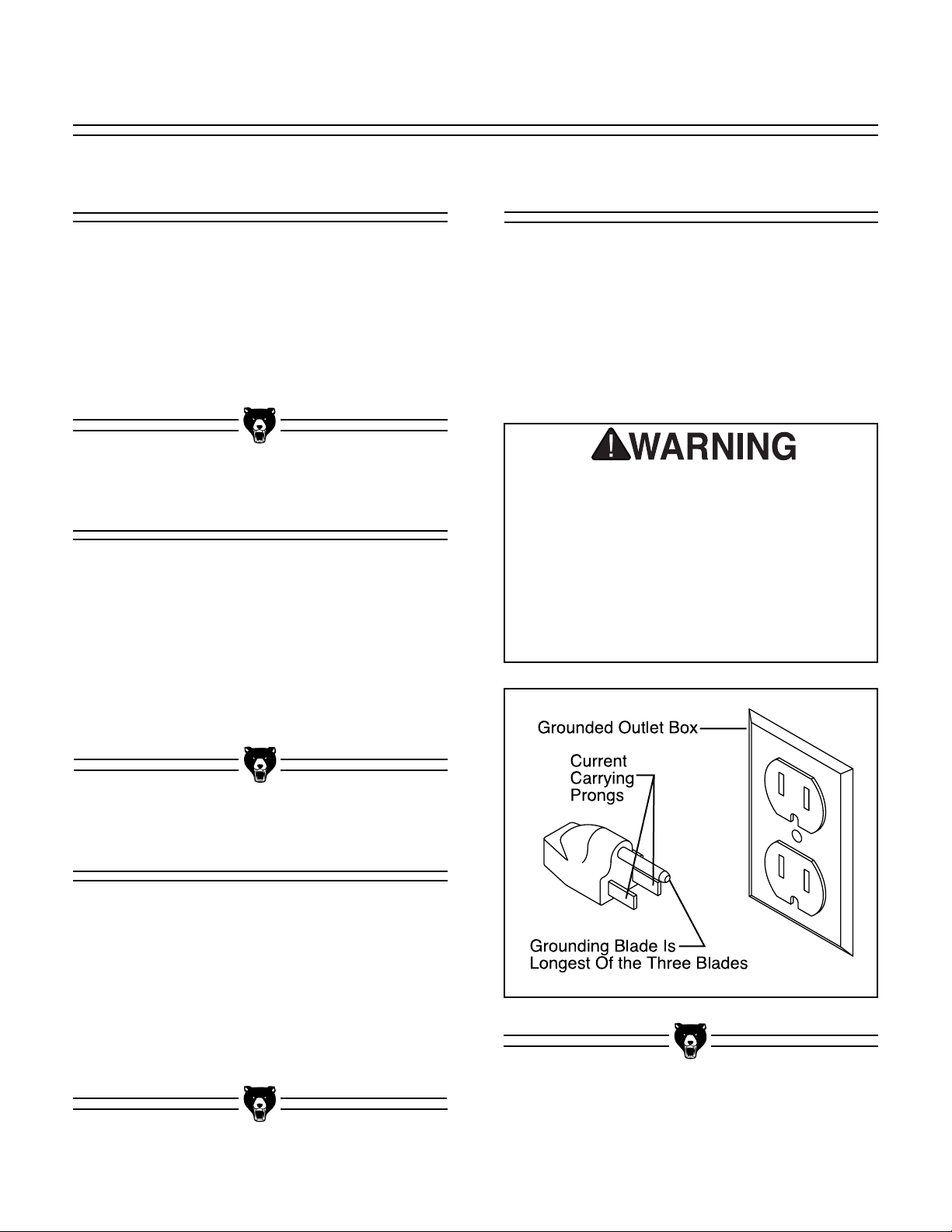
Grounding
This equipment must be grounded. Verify
that any existing electrical outlet and circuit
you intend to plug into is actually grounded. If it is not, it will be necessary to run a
separate 12 A.W.G. copper grounding wire
from the outlet to a known ground. Under
no circumstances should the grounding pin
from any three-pronged plug be removed.
Serious injury may occur.
In the event of an electrical short, grounding
reduces the risk of electric shock by providing a
path of least resistance to disperse electric current. This tool is equipped with a power cord having an equipment-grounding conductor. See
Figure 1. The outlet must be properly installed
and grounded in accordance with all local codes
and ordinances.
The Model G1015 is wired for 110/120V, single
phase operation only. The 1-HP motor will safely
draw 10 amps at 110V. If you operate this sander
on any circuit that is already close to its capacity,
it might blow a fuse or trip a circuit breaker.
However, if an unusual load does not exist and a
power failure still occurs, contact a qualified electrician or our service department.
Figure 1. Grounded plug configuration.
Page 7

-7- G1015 Knife Belt Sander/Buffer
SECTION 3: INTRODUCTION
We are proud to offer the Grizzly Model G1015
Knife Belt Sander/Buffer. The Model G1015 is
part of a growing Grizzly family of fine woodworking and metalworking machinery. When
used according to the guidelines set forth in this
manual, you can expect years of trouble-free,
enjoyable operation and proof of Grizzly’s commitment to customer satisfaction.
The Model G1015 combines a 2" x 72" belt with
a universal
5
⁄8" arbor which can accommodate a
number of accessories including buffing wheels,
drum sanders, or flap sanders (not included).
The 2" wide belt enables you to sand small or
finely-detailed pieces, or sharpen knives and tool
blades as described later in this manual. The
G1015 comes complete with motor and electrical
package.
A number of sanding drums and belts for the
Model G1015 are available through the Grizzly
catalog.
We are also pleased to provide this manual with
the Model G1015. It was written to guide you
through assembly, review safety considerations,
and cover general operating procedures. It represents our effort to produce the best documentation possible. If you have any comments regarding this manual, please write to us at the address
below:
Grizzly Industrial, Inc.
C
/O Technical Documentation
P.O. Box 2069
Bellingham, WA 98227-2069
Most importantly, we stand behind our machines.
If you have any service questions or parts
requests, please call or write us at the location
listed below.
Grizzly Industrial, Inc.
2406 Reach Road
Williamsport, PA 17701
Phone: (570) 326-3806
Fax: (800) 438-5901
E-Mail: techsupport@grizzly.com
Web Site: http://www.grizzly.com
The specifications, drawings, and photographs
illustrated in this manual represent the Model
G1015 as supplied when the manual was prepared. However, owing to Grizzly’s policy of continuous improvement, changes may be made at
any time with no obligation on the part of Grizzly.
Whenever possible, though, we send manual
updates to all owners of a particular tool or
machine. Should you receive one, we urge you to
insert the new information with the old and keep
it for reference.
To operate this, or any power tool, safely
and efficiently, it is essential to become as
familiar with its characteristics as possible.
The time you invest before you begin to use
your Model G1015 will be time well spent.
DO NOT operate this machine until you are
completely familiar with the contents of this
manual. Make sure you read and understand all of the safety procedures. If you do
not understand something, DO NOT operate
the machine.
Commentary
Page 8
G1015 Knife Belt Sander/Buffer -8-
Unpacking
This Knife Belt Sander/Buffer is shipped from the
manufacturer in two carefully packed cartons. If
you discover the machine is damaged after
you’ve signed for delivery, and the truck and driver are gone, you will need to file a freight claim
with the carrier. Save the containers and all packing materials for possible inspection by the carrier or its agent. Without the packing materials, filing a freight claim can be difficult. If you need
assistance determining whether you need to file a
freight claim, or with the procedure to file one,
please contact our Customer Service.
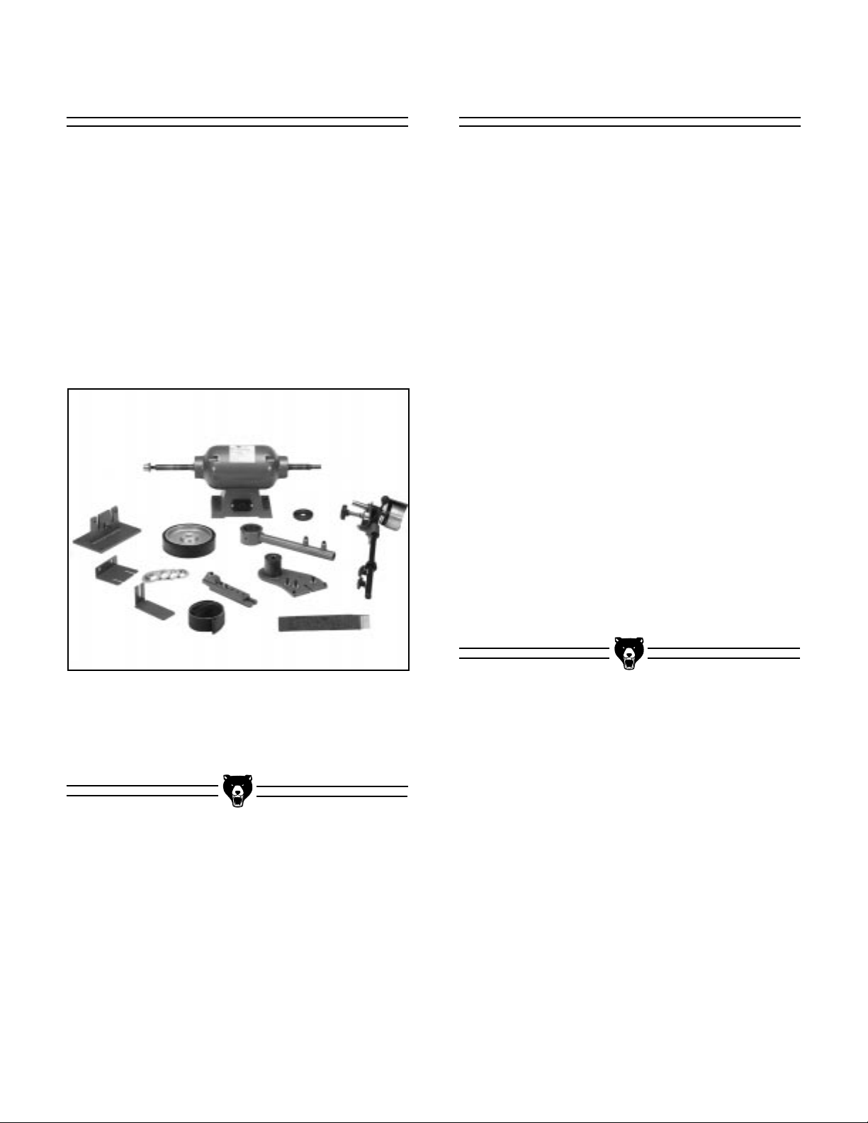
Parts Inventory
Figure 2 displays all of the parts you should have
after you unpack the boxes. You should have the
following items:
• Motor Unit
• Hex Nut, Right Hand Thread
• Shoulder Nut, Left Hand Thread
• Wheel Flanges (2) -
3
⁄4'' ID
• Wheel Flanges (2) -
5
⁄8'' ID
• Round Spacer
• Mounting Bracket, Sanding Arm
• Pivot Arm Bracket, w/ Large Bushing
• Lower Pivot Arm
• Upper Sanding Arm Assembly
• Drive Wheel
• Sanding Belt Shoe
• Shoe Mounting Bracket
• Tool Rest Mounting Bracket Assembly
• Tool Rest
• Sanding Belt 100 Grit
The hardware needed to assemble this machine
has generally been fastened to the component
part. A complete listing of hardware and all detail
parts is included in the parts lists and diagrams
located at the back of this manual.
When you are completely satisfied with the condition of your shipment, you should inventory its
parts.
Figure 2. Overview of parts.
Page 9

-9- G1015 Knife Belt Sander/Buffer
Clean Up
BENCH LOAD
Your G1015 Knife Belt Sander/Buffer represents
a relatively large weight load in a small footprint.
Be sure that your workbench is adequately reinforced to support the weight of the machine.
WORKING CLEARANCES
Working clearances can be thought of as the distances between machines and obstacles that
allow safe operation of every machine without
limitation. Ensure that your working area offers
plenty of room for free movement and a substantial amount of distance between you and others
that may be working in your shop area.
LIGHTING AND OUTLETS
Lighting should be bright enough to eliminate
shadow and prevent eye strain. Electrical circuits
should be dedicated or large enough to handle
combined motor amp loads. Outlets should be
located near each machine so power or extension cords are not obstructing high-traffic areas.
Be sure to observe local electrical codes for proper installation of new lighting, outlets, or circuits.
Make your shop “child safe”. Ensure that
your workplace is inaccessible to youngsters by closing and locking all entrances
when you are away. Never allow visitors in
your shop when assembling, adjusting or
operating equipment.
Site Consideration
Unpainted machine surfaces may be coated with
a waxy oil to protect it from corrosion during shipment. Remove this protective coating with a solvent cleaner or citrus-based degreaser. Avoid
chlorine-based solvents as they may damage
painted surfaces should they come in contact.
Always follow the usage instructions on the product you choose for clean up.
Many of the solvents commonly used to
clean machinery can be highly flammable,
and toxic when inhaled or ingested. Always
work in well-ventilated areas far from
potential ignition sources when dealing
with solvents. Use care when disposing of
waste rags and towels to be sure they do
not create fire or environmental hazards.
Keep children and animals safely away
when cleaning and assembling this
machine.
Do not use gasoline or other petroleumbased solvents to remove this protective
coating. These products generally have low
flash points which makes them extremely
flammable. A risk of explosion and burning
exists if these products are used. Serious
personal injury may occur.
Page 10

G1015 Knife Belt Sander/Buffer -10-
SECTION 4: ASSEMBLY
Mounting Base
All die-cut metal parts have a sharp edge
(called “flashing”) on them after they are
formed. This is generally removed at the
factory. Sometimes a bit of flashing might
escape inspection, and the sharp edge may
cause cuts or lacerations when handled.
Please examine the edges of all die-cut
metal parts and file or sand the edge to
remove the flashing before handling them.
Failure to do so could result in injury.
Figure 3. Bolt pattern for base. All dimensions are measured at hole centers.
Before assembly can be completed, the Model
G1015 motor base and belt sander base must
both be mounted to a bench, or a wooden base,
to provide the stability necessary for safe operation. If you choose to create a wooden base for
more portable operation, we recommend laminating two 20" x 12" x
3
⁄4" pieces of plywood togeth-
er, or use 1'' thick MDF (medium density fiberboard). For a wooden base, you may also want to
countersink the underside to accommodate the
hex nut and washers so the base will sit flat.
The layout in Figure 3 provides the recommended pattern for both motor base and sander base
mounting. Because of variation in the castings,
you may want to drill only the holes for the motor
base, then drill the sander base holes later after
you have mounted the pivot arm assembly.
Holes should be drilled for
5
⁄16" lag bolts (1⁄4" pilot
hole) or 5⁄16" machine bolts (1⁄2" diameter will allow
some minor adjustment). Mounting hardware is
not included. If using machine bolts, use a lock
washer secured between a flat washer and the
nut to ensure the bolt will not loosen during operation. Continue with the mounting procedure as
described in the following pages.
Page 11

-11-
Motor
Place the motor over its mounting holes as
shown in Figure 4 and secure with 5⁄16" machine
bolts or 5⁄16" lag bolts.
Figure 4. Motor secured to base.
Pivot Arm
1. Secure the round mounting spacer to the
end bell of the motor using three (3) 1⁄4 - 20
x 1⁄2'' cap screws. See Figure 5. Make sure
the cap screws go into the countersunk
side of the spacer plate. The flat edge of
the spacer should be positioned at the 10
o’clock position if you are looking directly at
the end of the motor.
Figure 5. Mounting spacer to end bell.
Flat Edge
Figure 6. Bracket assembly attachment.
2. Back off the two setscrews at the bottom of
the pivot arm and remove it from the pivot
arm bracket. This is a tight fit and it may
require moving the arm back and forth to
get it to come off of the bushing. Assemble
the pivot arm bracket to the mounting
bracket as shown in Figure 6. Align the
open ended slots with the three (3)
5
⁄16" - 18
x 1" cap screws which are already threaded
into place on the two brackets. Leave these
cap screws loose for now. If there are
setscrews installed on the two brackets,
these may be removed, they are no longer
used for the current method of assembly.
Slide this assembly over the shaft on the
right hand side of the motor. Use three (3)
1
⁄4'' - 20 x 1⁄2'' cap screws to attach the pivot
arm bracket to the spacer.
Pivot Arm
Bracket
Mounting Bracket
G1015 Knife Belt Sander/Buffer
Page 12

G1015 Knife Belt Sander/Buffer -12-
Drive Wheel
The drive wheel propels the sanding belt. To
secure the drive wheel to the motor shaft:
1. Slide a wheel flange, cupped side out, over
the motor shaft.
2. Slide the drive wheel over the motor shaft
3. Secure with the motor shaft hex nut. See
Figure 8.
Figure 8. Attaching drive wheel.
3. Tighten the three (3)
5
⁄16" - 18 x 1" cap screws
which hold the pivot arm bracket to the
mounting bracket. Make sure this assembly
is pushed far enough back that the bottom
of the pivot arm bracket is approximately
parallel to the base.
4. The mounting bracket can now be attached
to the base or benchtop. Drill holes for the
bracket using the four holes in the bracket
as a guide (if you did not already pre-drill
these holes). Secure with 5⁄16" machine bolts
or 5⁄16" lag bolts.
5. Reattach the pivot arm by sliding it onto the
bushing. The two welded bosses should be
pointed outward as shown in Figure 7.
Tighten the two setscrews on the pivot arm.
After assembly, the belt sander can be tilted at any angle from vertical to horizontal
by loosening and tightening those two
setscrews.
Figure 7. Pivot arm adjustment.
Welded
Bosses
Page 13

-13- G1015 Knife Belt Sander/Buffer
Upper Arm Assembly
Figure 9. Tightening sanding arm knobs.
Figure 10. Attaching sanding belt shoe.
To attach the upper sanding arm assembly:
1. Make certain the two (2) setscrews on the
bottom of the pivot arm are firmly tightened.
When the additional weight of the upper arm
assembly is added, you do not want the pivot
arm to flop over.
2. Remove the two (2) hand knobs from the
pivot arm and slide the upper sanding arm
assembly into the lower pivot arm. The sanding arm should seat on the collar.
3. Align the holes and replace the hand knobs
and tighten. See Figure 9.
Sanding Belt Shoe
Attach the sanding shoe mounting bracket
assembly to the pivot arm and secure the two (2)
cap screws with a 6 mm Allen
®
wrench.
Now attach the shoe with the graphite surface to
the mounting bracket as shown in Figure 10.
Secure these two (2) cap screws with a 6 mm
Allen
®
wrench. Both of these sets of mounting
bolts are slotted and allow adjustment of the shoe
in and out, and side to side. After the belt is
installed you will want to do a final adjustment to
the shoe so it just makes light contact with the
back of the belt, and make certain it is centered
on the belt.
Do not attempt to turn on the machine until
assembly and adjustments are completed.
Turn off the power switch and ensure that
the machine is unplugged. Failure to do so
could result in serious operator injury.
Page 14

G1015 Knife Belt Sander/Buffer -14-
Tool Rest
The tool rest provides secure, angle-adjustable
support for your workpiece while sanding. To
install the tool rest:
1. Attach the tool rest bracket to the pivot arm
bracket with the 5⁄16" - 18 x 1" cap screw and
flat washer included. See Figure 12.
2. Attach the tool rest to the tool rest bracket
with the 5⁄16" - 18 x 3⁄4" cap screw and flat
washer included.
Figure 12. Tool rest attachment
Belt Installation
To install or replace the sanding belt:
1. If you are using a different length belt than
the one supplied (72'') you will need to
adjust the distance between the two
wheels. See Section 5: Adjustments, Belt
Tension for more detail.
2. Locate a position where the belt fits snugly
over both the upper and lower drive
wheels.
3. Remove the belt and raise the upper
assembly approximately
1
⁄4". Tighten the
two (2) knobs.
4. Depress the belt tensioning knob. See
Figure 11.
5. After making sure that the direction arrows
on the belt match the direction of movement, slip the belt over the upper and lower
drive wheels and center it on the wheels.
Figure 11. Attaching sanding belt.
Belt
Tensioning
Knob
Sanding or polishing operations can be performed against either the sanding shoe of the
drive wheel as a backstop. If sanding against
the drive wheel, remove the tool rest and its
support bracket to make sure the workpiece
does not jam against the rest. This can create
a pinch point trapping a finger against the belt.
Page 15

-15- G1015 Knife Belt Sander/Buffer
SECTION 5: Adjustments
Belt Tension
The Model G1015 features a self-tensioning
mechanism which automatically applies tension
to the sanding belt. If you are using a different
length belt than the one supplied (72'') you will
need to adjust the distance between the two
wheels. To adjust the tensioning:
1. Pull down the tensioning knob and remove
the sanding belt.
2. Loosen the hand knobs on the pivot arm
and raise or lower the upper assembly to
increase or decrease the distance between
the wheels. See Figure 13. You may need
to loosen the stop collar to allow the necessary movement.
Figure 13. Length adjustment for upper arm.
Stop Collar
3. Replace the sanding belt onto the wheels
and inspect for tension. Be sure the tracking adjustment is set so the upper wheel
shaft is almost perpendicular. The belt
should deflect approximately
1
⁄2'' inch when
you press against it. Check it on the back
loop of the belt where it comes up from the
drive wheel to the upper wheel. This way
the deflection will not be affected by the
sanding shoe. Repeat step 2 if needed.
Tool Rest
The tool rest should be adjusted so it is positioned in front of the sanding belt shoe’s graphite
surface. The clearance between the tool rest and
the belt should be no more than
1
⁄8'' to ensure that
nothing can become trapped between the belt
and the rest. The angle of the rest relative to the
belt surface can be adjusted by loosening the cap
screw, adjusting the rest angle and re-tightening
the cap screw.
The height of the tool rest can also be adjusted
by removing the two (2)
5
⁄16" - 18 x 11⁄4" cap screws
holding the two halves of the tool rest bracket
together. Selection of different hole combinations
results in varying lengths. The tool rest should be
set high enough so that it is located over the
graphite pad portion of the sanding shoe.
Page 16

G1015 Knife Belt Sander/Buffer -16-
Figure 15. Relieving edges of drive wheel.
Belt Tracking
Proper angulation between the upper and lower
drive wheels will result in a sanding belt which
remains centered during operation. To adjust for
proper tracking:
1. Turn the drive wheel several revolutions by
hand. If the belt begins to shift from its center position to the right or left, tracking
adjustment will be needed. Be careful when
adjusting to make sure the belt does not
run off the lower drive wheel and hit the
mounting bracket. The edge of the sanding
belt can be easily damaged.
2. Continue to hand rotate the belt and with
your other hand, turn the large tracking
knob at the top of the arm right or left until
the belt centers itself on the upper wheel.
See Figure 14.
If the belt will not track properly, it is possible that
realignment of the wheels is required.
Figure 14. Upper arm tracking adjustments.
Tracking Knob
Wheel Adjustment
Belt Tension
Knob
Since the lower drive wheel positioning is fixed,
tracking adjustment requires aligning the
upper wheel:
1. Loosen the two (2) setscrews and slide the
upper wheel shaft in or out until it is approximately the same distance out as the lower
wheel. A straightedge can be used to aid in
this alignment. Tighten the setscrews.
2. Reinstall the sanding belt and repeat the
tracking procedure outlined in Steps 1 and 2.
If the belt is still not staying properly positioned, it
could be that the entire upper head assembly is
rotated out of position. Loosen the two setscrews
at the top of the upper arm post. Sight down on
the assembly and visually align the top wheel so
it is parallel with the drive wheel. Tighten the
setscrews.
The final solution to tracking problems is to lightly bevel the edge of the rubber surface of the
drive wheel. Sometimes the edge of the wheel is
raised just enough to cause problems. Use a rasp
lightly against the running drive wheel to just
slightly relieve the edge of the wheel surface. See
Figure 15.
Page 17

-17- G1015 Knife Belt Sander/Buffer
SECTION 6: Operations
Before you put your Belt Sander/Buffer into use,
give it a quick inspection. Before inspecting,
ensure that the machine is switched off and disconnected from its power source.
1. Are all mounting fasteners tight?
2. Is the sanding belt properly tracked and
tensioned?
3. Rotate the drive wheel slowly by hand.
Look and listen for any scraping noises or
anything that impedes smooth movement.
Make appropriate adjustments before
attempting to run the machine.
4. If the sander appears to be free of prob-
lems that might affect its operation, plug it
in to its power source and start the
machine. Be sure to keep a finger on the
OFF button, just in case of a problem with
the machine. Run the machine briefly to
allow inspection of belt tracking.
5. Turn off the machine, disconnect it from its
power source, and re-inspect for loose fasteners. If the tracking is not correct, refer to
the tracking adjustment guidelines in the
Adjustments section.
Never use the Model G1015 for applications
other than those for which it was made. DO
NOT overload the machine or use excess
force when sanding. Severe personal
injury, damage to the machine, or damage
to your workpiece could occur.
Test Run
Figure 16. Belt sanding wood.
The sanding belt can be used to sand wood or
metal. We recommend aluminum oxide sanding
belts for wood and silicon carbide for metal.
Always be sure the belt is properly installed so
the direction of rotation arrows follow the direction
of rotation of the drive wheel. This keeps the
seam in the belt oriented so it will not catch on the
workpiece. The 2" belt width, used in conjunction
with the graphite-faced sanding shoe provides an
excellent surface for angular sanding or polishing.
The tool rest should always be adjusted so it is no
more than
1
⁄8" away from the belt surface. This
helps to assure that nothing can get trapped
between the rest and the belt.
Figure 16 shows a typical wood sanding operation with the tool rest perpendicular to the belt
surface. The tool rest can be checked for squareness to the belt by placing a machinist’s square or
try square on the tool rest and adjusting the angle
of the rest.
Belt Sanding
Page 18

G1015 Knife Belt Sander/Buffer -18-
Figure 18. Contour sanding, shoe removed.
Figure 17. Typical knife sharpening technique.
The sanding arm can also be tilted to a horizontal
position if desired. See Figure 19. This can be
more convenient for certain types of sanding or
polishing operations. Make sure the arm is
secured in the horizontal position with the two
setscrews on the bottom of the pivot arm. It will
also be necessary to adjust the tool rest so it is in
the proper orientation for horizontal use. If you
are going to sand against the contour of the drive
wheel itself, the tool rest should be removed so it
will not interfere with access.
Be certain before attempting to tilt the sanding
arm that the motor and mounting bracket are firmly attached to a benchtop or base.
Figure 19. Pivot arm in horizontal position.
The belt can also be used for contour sanding. It is best when doing this type of operation to remove the graphite faced sanding
shoe so the belt can flex to conform better to
the shape you are sanding. See Figure 18.
The belt can also be used for knife grinding
and sharpening. Figure 17 depicts a typical
knife edge grinding operation. Generally this
will be done with the tool rest removed.
Page 19

-19- G1015 Knife Belt Sander/Buffer
For buffing and polishing, Grizzly offers a broad
selection of buffing wheels and polishing compounds that are very well suited for use with the
Model G1015. Please refer to our current catalog.
The auxiliary motor shaft arbor accepts buffing
wheels with a
5
/8'' bore. See Figure 20.
Buffing & Polishing
Pieces of the buffing wheel or buffing compound can be expelled from the machine at
extremely high speeds. Always wear ANSIapproved safety glasses to avoid injury to
your eyes.
Never introduce a sharp edge of a workpiece into the direction of rotation.
Always work with the rotation direction.
Workpieces can be pulled from your grasp
if forced into the wheel, or if too much pressure is used while buffing. Serious personal injury could result.
Figure 20. Optional buffing wheel attached.
Figure 21. Buffing on the bottom of the wheel.
6. Firmly grasp the item to be polished with
both hands. Lightly and evenly move the
item across the face of the wheel until the
surface is polished. Use extra care when
polishing plated materials. Over-buffing can
completely remove plating when exposed
to the abrasive wheel for too long.
To buff and polish:
1. Make sure the machine is off and the power
cord is unplugged. Remove the left-handed
nut at the end of the shaft.
2. Sandwich an optional buffing wheel
between two wheel flanges and slide onto
the shaft.
3. Tighten the nut with one hand while holding
the shaft with the other. The left-handed
rotation will ensure that the nut stays tight
during operation.
4. With a brand new buffing wheel it is neces-
sary to charge the wheel with compound
before the first use. Follow the directions
which come with the buffing wheel and
compound.
5. If facing the front of the machine, buffing
and polishing should be done on the bottom of the wheel. See Figure 21.
Page 20

G1015 Knife Belt Sander/Buffer -20-
Drum Sanding
To sand using the optional pneumatic sanding
drum:
1. Slide the optional sanding drum onto the
shaft so the valve end is near the end of the
shaft. Secure with the shaft nut provided. It is
not necessary to use wheel flanges with the
drum. See Figure 22.
Figure 22 Sanding drum attached.
Figure 23. Recommended sleeve overlap.
4. Inflate the drum using a bicycle pump or
hand pump. DO NOT over-inflate. The recommended air pressure for the drum is 10
psi.
5. Turn on the machine and apply light, even
pressure between the workpiece and the
sanding drum.
NOTICE
Machine sanding has the capability of removing
large amounts of material very rapidly. Be sure
to check on the progress of your sanding frequently to avoid removing more material than is
desired.
2. Ensure that the nut seats into the sanding
drum. Tighten the nut while holding the
sanding drum or the belt drive wheel. Use
care not to pinch your fingers against the
pivot arm bracket.
3. Slide sanding sleeve onto the drum. Ensure
that the arrows on the inside of the sleeve
correspond to the direction of the drum
movement. If the sleeve has no arrows,
slide the sleeve on the drum so the overlap
is at the trailing edge of the drum movement. See Figure 23.
Accessory Removal
To remove buffing or sanding attachments,
ensure that the switch is in the OFF position and
the power cord is disconnected. Hold onto the
shaft or drum sander with one hand and loosen
the nut with a wrench. If the shaft slips inside of
the drum, loosen the nut while holding the belt
sander drive wheel. Remember: the auxiliary
wheel has left-hand (reverse) threads.
NOTICE
Do not use a compressor to inflate the pneumatic sanding drum, it is too easy to overinflate. Use a hand-operated pump only, and
check the inflation pressure with a suitable
gauge.
Page 21

-21- G1015 Knife Belt Sander/Buffer
SECTION 7: MAINTENANCE
General
Make a habit of inspecting your sander each
time you use it. Check for the following conditions and repair or replace when necessary.
1. Loose mounting bolts.
2. Worn switch.
3. Worn or damaged cords and plugs.
4. Poor belt tensioning ⁄ tracking.
Lubrication
Belts and Drums
The sanding belt supplied with your G1015 is a
100 grit aluminum oxide belt suitable for general
purpose wood sanding. Other applications, such
as metal sanding and polishing will require different types of belts, both in composition and in grit.
Please consult the latest Grizzly catalog for a
complete selection of sanding media for all your
project needs.
To replace the belt, see Section 4: Assembly
Belt Installation.
If the replacement belt is a different length than
the original belt, it may be necessary to re-adjust
the upper assembly as described in the Section
5: Adjustments, Belt Tension.
Operating this equipment has the potential
to launch flying debris which could cause
eye injury. Always wear safety glasses or
goggles when operating equipment.
Everyday glasses or reading glasses only
have impact resistant lenses, they are not
safety glasses. Be certain the safety glasses you wear meet the appropriate standards of the American National Standards
Institute (ANSI).
The motor and sanding arm bearings are shielded and pre-lubricated and require no lubrication.
The inside bore of the pivot arm is already coated with grease which allows smooth movement of
the arm around the bushing. In the event you
need to disassemble the pivot arm at a later date,
it is always a good idea to replace this grease
(use a multi-purpose grease).
Page 22

G1015 Knife Belt Sander/Buffer -22-
The following pages contain general machine
data, parts diagrams/lists, troubleshooting guide
and Warranty/Return information for your Model
G1015 Knife Belt Sander/Buffer.
If you need parts or help in assembling your
machine, or if you need operational information,
we encourage you to call our Service
Department. Our trained service technicians will
be glad to help you.
If you have comments dealing specifically with
this manual, please write to our Bellingham,
Washington location using the address in Section
3: Introduction. The specifications, drawings, and
photographs illustrated in this manual represent
the Model G1015 as supplied when the manual
was prepared. However, due to Grizzly’s policy of
continuous improvement, changes may be made
at any time with no obligation on the part of
Grizzly. Whenever possible, though, we send
manual updates to all owners of a particular tool
or machine. Should you receive one, add the new
information to this manual and keep it for reference.
We have included some important safety measures that are essential to this machine’s operation. While most safety measures are generally
universal, Grizzly reminds you that each workshop is different and safety rules should be considered as they apply to your specific situation.
We recommend you keep a copy of our current
catalog for complete information regarding
Grizzly's warranty and return policy. If you need
additional technical information relating to this
machine, or if you need general assistance or
replacement parts, please contact the Service
Department listed in Section 3: Introduction.
Additional information sources are necessary to
realize the full potential of this machine. Trade
journals, woodworking magazines, and your local
library are good places to start.
SECTION 8: CLOSURE
The Model G1015 was specifically designed
for sanding operations only. DO NOT MODIFY
AND/OR USE THIS MACHINE FOR ANY
OTHER PURPOSE. Modifications or
improper use of this tool will void the warranty. If you are confused about any aspect of
this machine, DO NOT use it until you have
answered all your questions. Serious person-
al injury may occur.
Like all power tools, there is danger associated with the Model G1015 Knife Belt
Sander Buffer. Accidents are frequently
caused by lack of familiarity or failure to
pay attention. Use this tool with respect and
caution to lessen the possibility of operator
injury. If normal safety precautions are
overlooked or ignored, serious personal
injury may occur.
Operating this equipment has the potential
to launch flying debris which could cause
eye injury. Always wear safety glasses or
goggles when operating equipment.
Everyday glasses or reading glasses only
have impact resistant lenses, they are not
safety glasses. Be certain the safety glasses you wear meet the appropriate standards of the American National Standards
Institute (ANSI).
Page 23

-23- G1015 Knife Belt Sander/Buffer
SYMPTOM
Motor will not start.
Motor will not start;
fuses or circuit breakers blow.
Motor fails to develop
full power (power output of motor decreases rapidly with
decrease in voltage at
motor terminals).
Motor overheats.
Motor stalls (resulting
in blown fuses or
tripped circuit).
Machine slows down
when operating.
TROUBLESHOOTING - MOTOR
POSSIBLE CAUSE
1. Low voltage.
2. Open circuit in motor or
loose connections.
1. Short circuit in line cord
or plug.
2. Short circuit in motor or
loose connections.
3. Incorrect fuses or circuit
breakers in power line.
1. Power line overloaded
with lights, appliances,
and other motors.
2. Undersized wires or circuits too long.
3. General overloading of
power company facilities.
1. Motor overloaded.
2. Air circulation through
the motor restricted.
1. Short circuit in motor or
loose connections.
2. Low voltage.
3. Incorrect fuses or circuit
breakers in power line.
4. Motor overloaded.
Applying too much
pressure to workpiece.
CORRECTIVE ACTION
1. Check power line for proper voltage.
2. Inspect all lead connections on motor for
loose or open connections.
1. Inspect cord or plug for damaged insulation and shorted wires.
2. Inspect all connections on motor for loose
or shorted terminals or worn insulation.
3. Install correct fuses or circuit breakers.
1. Reduce load on power line.
2. Increase wire sizes or reduce length of
wire.
3. Request a power check from the power
company.
1. Reduce load on motor.
2. Clean out motor vents underneath housing to provide normal air circulation.
1. Inspect connections on motor for loose or
shorted terminals or worn insulation.
2 Correct the low voltage conditions.
3. Install correct fuses or circuit breakers.
4. Reduce load on motor.
Feed workpiece slower.
Page 24

G1015 Knife Belt Sander/Buffer -24-
SYMPTOM
Abrasive belt runs off
top wheel.
Belt breaking or tearing prematurely.
Belt makes grinding
noise when started.
Pivot arm will not
rotate to horizontal.
TROUBLESHOOTING - OTHER
POSSIBLE CAUSE
Not tracking properly.
1. Belt tension too tight.
2. Belt rotation incorrect.
3. Inferior quality belt.
1. Belt rubbing against
upper or lower housings.
2. Tool rest interfering with
belt.
3. Graphite surface of
sanding shoe worn out.
4. Upper wheel bearings
worn or damaged.
1. Arm held by locking
setscrews.
2. Arm needs lubrication.
CORRECTIVE ACTION
1. Adjust upper wheel with tracking knob.
2. Make sure upper wheel is aligned with
drive wheel.
3. Sanding shoe may be interfering. Adjust
so it is square to the belt.
4. Bevel the outer edges of the drive wheel
slightly.
1. Adjust tension by changing height of
upper arm assembly.
2. Make sure belt direction arrows are going
in the right direction.
3. Purchase different type or quality belt.
1. Adjust belt tracking.
2. Adjust tool rest clear of belt surface.
3. Replace graphite pad.
4. Replace bearings.
1. Loosen both setscrews.
2. Remove pivot arm and grease bushing.
Page 25

-25- G1015 Knife Belt Sander/Buffer
WARRANTY AND RETURNS
Grizzly Industrial, Inc. warrants every product it sells for a period of 1 year to the original purchaser from
the date of purchase. This warranty does not apply to defects due directly or indirectly to misuse, abuse,
negligence, accidents, repairs or alterations or lack of maintenance. This is Grizzly’s sole written warranty
and any and all warranties that may be implied by law, including any merchantability or fitness, for any particular purpose, are hereby limited to the duration of this written warranty. We do not warrant or represent
that the merchandise complies with the provisions of any law or acts unless the manufacturer so warrants.
In no event shall Grizzly’s liability under this warranty exceed the purchase price paid for the product and
any legal actions brought against Grizzly shall be tried in the State of Washington, County of Whatcom.
We shall in no event be liable for death, injuries to persons or property or for incidental, contingent, special, or consequential damages arising from the use of our products.
To take advantage of this warranty, contact us by mail or phone and give us all the details. We will then
issue you a “Return Number’’, which must be clearly posted on the outside as well as the inside of the carton. We will not accept any item back without this number. Proof of purchase must accompany the merchandise.
The manufacturers reserve the right to change specifications at any time because they constantly strive to
achieve better quality equipment. We make every effort to ensure that our products meet high quality and
durability standards and we hope you never need to use this warranty.
Please feel free to write or call us if you have any questions about the machine or the manual.
Thank you again for your business and continued support. We hope to serve you again soon.
 Loading...