


Model RC400
Single Cup Brewer
Operation Manual
Table of Contents
Safety Precautions ……………………...2 Brewer Specifications …………………..3 General Information …………………….3
Product Description …………………….4
Unpacking your brewer ………………...5
Installation ……………………………….5
Set-up ……………………………………6
Operating Instructions…………………..7 Cleaning and Maintenance …………....9 Troubleshooting………………………..10
Spare Parts List ……………………….11
Warranty ……………………………….12
Prior authorization must be obtained from GMCW for all warranty claims.
GRINDMASTER ® BY GMCW ™
© GMCW, 2013
Printed in Thailand
MODEL: RC400
GMCW
4003 Collins Lane Louisville, KY 40245 USA (502) 425-4776
(800) 695-4500 (USA & Canada only) FAX (502) 425-4664 www.gmcw.com
1213 Form # BW-305-01
Part # 390-00005
ENGLISH

2
Safety Precautions
Important Safety Information
This is the safety alert symbol. It is used to alert you to potential personal injury hazards. Obey all safety messages that follow this symbol to avoid possible injury or death.
For your safety and the safety of others, read all warnings and the operator’s manual before installing or using the product.
DANGER: This term warns of imminent hazard that will result in serious injury or death.
WARNING: This term refers to a potential hazard or unsafe practice, which could result in serious injury. CAUTION: This term refers to a potential hazard or unsafe practice, which could result in minor or moderate injury or property damage.
NOTICE: This term refers to information that needs special attention or must be fully understood.
DANGER
To prevent the possibility of electrocution, burns, or other injuries and to prevent damage to your brewer, do not immerse in water or any cleaning liquids.
Do not operate a damaged brewer. Inspect the power supply cord and water supply often. If cord or plug is damaged or worn, do not use your brewer. Turn off the water supply and disconnect the electrical power.
Turn off and unplug the brewer before cleaning or maintenance.
Risk of suffocation. The product packaging contains a plastic bag. Keep plastic bags away from children.
Disconnect power if the machine functions abnormally and notify qualified service personnel for repairs. Do not permit non-qualified service personnel to attempt repairs. No user serviceable components inside the brewer. Do not disassemble the brewer.
WARNING
Brew probes are sharp. To prevent injury, do not place fingers inside the brew chamber.
The brewer must only be connected to a three wire 120 VAC, 60 Hz, 15 Amp, electrical circuit. Allow brewer to cool before cleaning or maintaining.
CAUTION
Risk of burns. The brewer uses 185°F- 200°F water that, if not properly handled, could cause burns. Do not permit children to use this appliance unless there is direct adult supervision. Keep away from pets and other animals.
For indoor use only. Do not install or use outdoors, in moving equipment, or watercraft.
Use the product for its intended purpose only. Any other usage is inappropriate and may be dangerous. The manufacturer assumes no responsibility for injury, loss or damage resulting from improper machine use.
To avoid the risk of burns, do not operate without bezel installed.
Hot surfaces may cause burns. Do not touch the brewer while in operation. To prevent scalding by hot water, do not open brew chamber while brewing.
To prevent scalding by hot water, do not move or tilt the brewer. Moving or tilting the brewer could result in water spilling from the reservoir. Internal boiling is possible at high elevations. You must reduce temperature set point below boiling point for your elevation.
To avoid scalding, use appropriate cup rest to minimize splash. Allow a minimum of 1/2” clearance between cup rim and brewer dispense spout to prevent spills when removing a full cup. Center cup with dispense spout while brewing and allow brewer cycle to complete before opening brew chamber or removing cup.
To avoid pinching, keep fingers clear of brew chamber when closing.
ENGLISH |
2 |
|
|

3
NOTICE
For best results, remove used Real Cup™ capsule from brew chamber when brewing is complete.
Avoid spills by not removing the reservoir while Auto-Fill unit is filling; allow complete filling cycle before removing reservoir.
A qualified professional should perform installation, maintenance and repairs.
Installation, maintenance or repairs by unqualified personnel may damage the brewer and void the manufacturer’s warranty.
This equipment must be installed in accordance with the appropriate national and local codes of the country and/ or region in which the appliance is installed.
Contact the manufacturer to report any malfunction of or damage to the brewer.
When turning the machine off for an extended period, be sure to evacuate the water inside the piping completely, otherwise the water inside the machine could freeze and lead to damage or cause mold to appear.
To reduce foreign material from entering the brewer, keep brew chamber and reservoir lids closed. To prevent accidental over filling of cup, press “BREW” to stop.
Brewer Specifications
Model |
RC400 |
Dimensions (H x W x D) |
15.7” (40 cm) x 10.8” (28 cm) x 14.8” (38 |
|
cm) |
Shipping Weight |
18.7 LBS (8.5 kg) |
|
|
Machine Weight |
15.3 LBS (6.9 kg) |
|
|
Reservoir Capacity |
72 fl. oz. (2.1 L) |
|
|
Voltage |
120 VAC |
|
|
Phase |
1 |
|
|
Frequency |
60 Hz |
|
|
Power |
1.55 KW |
Current |
13 Amps |
|
|
No. of Heaters |
1 |
|
|
NEMA Plug |
5-15P |
General Information
This operating manual includes instructions for using and maintaining your coffee brewer; keep this manual readily available.
After unpacking your brewer, check to ensure that your machine has not been damaged during shipping and includes all components. Notify your service representative regarding any questions or concerns before installing.
Please note that packaging material can be dangerous. Keep away from children. Discard promptly.
During various stages of operation, you may hear normal operating sounds that are unfamiliar. The following noises are normal:
Buzzing/Clicking - Heard when the water pump energizes and/or the three way valve opens and closes to dispense water or direct water to reservoir.
Popping – A damaged Real Cup™ capsule could result in a popping sound.
Pulsating/Whirring – Under normal operating conditions, an internal air pump activates at the end of a brewing cycle and you will hear it while energized.
ENGLISH |
3 |
|
|
4
Water running or gurgling – On a pour over installation, you will hear gurgling when reservoir is empty before the end of a brew cycle. On an auto fill installation, you will hear this sound as the brewer automatically refills.
Do not use a damaged Real Cup™ capsule or re-insert a capsule that has been previously been inserted & removed. This may result in coffee grounds and unwanted material inside the brew chamber and the drinking cup or mug. Damage to Real Cup™ capsule may be around the edge of the foil seal or denting and deforming the entire Real Cup™ capsule.
To ensure food safety and proper operation, clean machine regularly following the daily and weekly cleaning instructions. Cleaning and water evacuation instructions are found in the Cleaning and Maintenance Section of this manual.
When turning off the machine for an extended period, be sure to evacuate the water inside the piping completely. Otherwise, the water inside the machine could freeze and lead to damage or cause mold to appear.
Water pipe connections and fixtures directly connected to a potable water supply shall be sized, installed and maintained in accordance with federal, state and local codes. This product requires an approved back flow prevention device, such as a double check valve, to be installed between the machine and the water supply.
To prevent foreign material from entering the brewer, keep brew chamber and reservoir lid closed.
To ensure proper operation of the electronic controls, do not use reverse osmosis, distilled or de-ionized water.
The RC400 brewer hot water temperature is factory set at 195o F (90.6o C). If you brewer is operated above 4000 feet in elevation, set point adjustment may become necessary. If the brewer reservoir fogs or experiences hot water dripping into the reservoir this indicates the set point must be lowered. In addition, if the set point is too high, you could experience less than expected brew volumes.
Recommended |
Elevation ft(M) |
City |
Recommended |
Elevation ft(M) |
City |
Set Point oF |
|
|
Set Point oF |
|
|
(oC) |
|
|
(oC) |
|
|
200 (93) |
0 |
|
191 (88) |
5000 (1524) |
Denver/ |
|
|
|
|
|
Albuquerque |
|
|
|
|
|
|
198 (92) |
1000 (305) |
|
189 (87) |
6000 (1828) |
Colorado Springs |
|
|
|
|
|
|
196 (91) |
2000 (610) |
|
187 (86) |
7000 (2134) |
Santa Fe |
|
|
|
|
|
|
195 (90) |
3000 (915) |
Calgary |
185 (85) |
8000 (2438) |
|
|
|
|
|
|
|
193 (89) |
4000 (1219) |
|
|
|
|
|
|
|
|
|
|
Product Description
Thank you for purchasing the RealCup™ RC400 brewer. This brewer is a digitally controlled commercial/residential coffee brewer that brews one cup at a time. The brewer is designed for optimal use with RealCup™ capsules and is compatible with Keurig®* K-Cup®* capsules.
The Single Cup brewer can be plumbed into a potable water supply. If a water line is not available, the brewer can be used as a pour over brewer. The brewer requires a dedicated 15 amp, 120V, 60 Hz power source. If the brewer is plumbed, it will refill the reservoir itself automatically. If used as a pour over brewer, manually refill the reservoir as necessary.
The operating principle of this machine is that a user places a coffee mug on the drip tray (or foldaway tray), then places a fresh RealCup™ capsule in the brew chamber. The user then closes the chamber and selects, from the
*RealCup™ brand has no affiliation with K Cup® or Keurig Inc. Keurig® and K Cup® are registered trademarks of Keurig Inc.
ENGLISH |
4 |
|
|

5
user interface screen, their beverage and size choice. Once these selections are made, the BREW button is pressed. The brewer is designed to dispense 4 (118), 6 (177), 8 (237), 10 (296), 12 (355) and 16 (473) fluid ounces (ml). Actual dispensed volume is approximately 10% less to allow for addition of milk, cream or sweetener if desired.
Unpacking Your Brewer
1.Place carton on a table or a stable, firm surface.
2.Open the box. Do not use sharp objects to open the box. Doing so could cause damage to the brewer.
3.Remove enclosed protective materials, printed information, and the brewer.
4.Record the serial number inside the back cover of this manual.
5.After unpacking, check to ensure that your machine has not been damaged during shipping and includes all components.
6.Notify your service representative regarding any questions or concerns before installing.
RC400 Features
Screen
Reservoir Lid
Reservoir
Brew Chamber Lid
Brew Button
Bezel
Reservoir LED
 Power Switch
(Back side of brewer)
Pull Down Tray
Installation
Where to Install
Brewer should be installed on a firm, stable, level surface. Keep away from pets. Provide supervision for unattended children and assistance for others that require help to operate the brewer.
*RealCup™ brand has no affiliation with K Cup® or Keurig Inc. Keurig® and K Cup® are registered trademarks of Keurig Inc.
ENGLISH |
5 |
|
|

6
Water and Power Inlets |
Water Inlet |
|
Drain Tube Cover
Adapter (Auto-Fill ONLY)
Power Switch
Power Cord
Valve Cap (Pour Over ONLY)
Grommet
Water Supply
NOTICE: The brewer is designed to operate with water pressures from 10 psig up to 100 psig. Grindmaster requires the use of an external water filter such as Water Filter Kit P/N 250-00034. The filter mounts on the rear surface of the brewer.
Power Supply
WARNING
Disconnect power if the machine functions abnormally and notify qualified service personnel for repairs. Do not permit non-qualified service personnel to attempt repairs.
No user serviceable components inside the brewer. Do not disassemble brewer.
Notice
This appliance is equipped with a three wire power cord. A dedicated three wire 120V, 15A NEMA 5-15 electrical circuit must be used.
1.A dedicated 120 VAC, 60 Hz, 15 Amp, type 5-15, electrical circuit is required for proper operation.
2.Always unplug machine before servicing or maintaining the machine.
3.Place power switch in OFF position and plug power cord into the dedicated three wire 120V, 15A NEMA 5- 15 electrical circuit
Set-Up
Priming the internal heating tank
NOTE: The brewer will not operate until the tank is primed.
Please follow these procedures to ensure proper installation.
ENGLISH |
6 |
|
|
7
|
Pour Over version |
|
Auto-Fill version |
1. |
Ensure that the water inlet valve cap supplied with the |
1. |
Plumb water to the fill valve located on the back of |
machine is installed on the water inlet valve to prevent |
the brewer. A ¼” female flare x ¼” tube adapter as |
||
leaking. |
well as a ¼” flare x hose adapter provided with the |
||
|
|
brewer. Do not use reverse osmosis water. |
|
2. |
Open reservoir lid. |
2. |
Open water service valve. |
|
|
|
|
3. |
Fill reservoir with tap or bottled water to the level indi- |
3. |
Plug unit into a 120V/15 amp receptacle. Turn |
cated on reservoir. Do not use distilled water. |
main power switch to ON. |
||
4. |
Plug unit into a 120V/15 amps receptacle. Turn main |
4. |
Reservoir will automatically fill. |
power switch to ON. |
|
|
|
5. |
Place a cup in the drip tray of the unit to collect the wa- |
5. |
Place a cup in the drip tray of the unit to collect the |
ter from the priming operation. |
water from the purging operation. |
||
6. |
The screen will display "Prime Brewer". Press BREW |
6. |
The screen will display "Prime Brewer". Press |
button until water flows into cup. |
BREW button until water flows into cup. |
||
7. |
Refill the reservoir to the appropriate level. |
7. |
Allow brewer to reach brewing temperature. |
|
|
|
|
8. |
Allow brewer to reach brewing temperature. |
|
|
|
|
|
|
Note: Auto-Fill ONLY:
The water is supplied directly to the unit and the water fill level marking is not used. Operation is not affected by the water being below the fill line.
Fill Level 
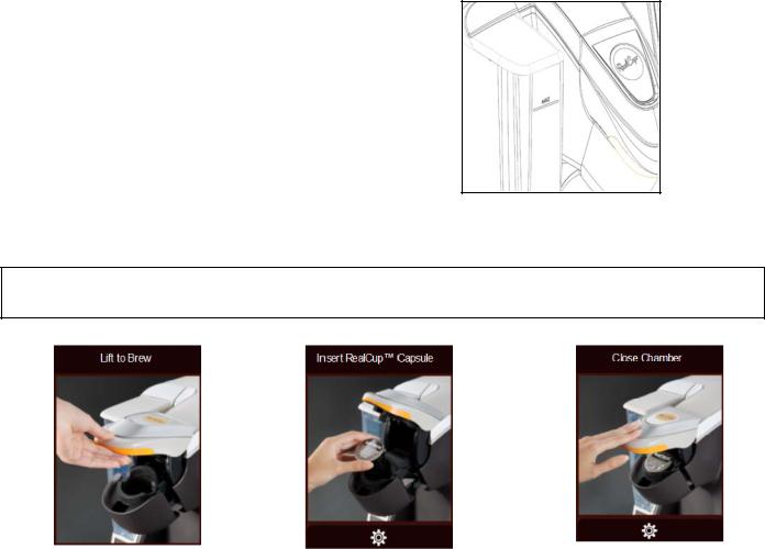
Operating Instructions
WARNING Brew probes are sharp. To prevent injury, do not place fingers inside the brew chamber. To prevent accidental overflow, press “BREW” to stop.
Step 1 – Lift brew chamber lid |
Step 2 – Insert RealCup™ capsule |
Step 3 – Close brew chamber |
ENGLISH |
7 |
|
|

8
Step 4 – Select settings |
Step 5 – Place cup & press |
|
brew button |
||
|
Step 6 – Remove RealCup™ capsule and enjoy
Brew Button Color
RED-BLUE-GREEN: Color start up sequence.
RED: Pulses during heating cycle. Light flashes if there is a fault.
YELLOW: Steady on when brew chamber is open.
GREEN: Steady on when ready to brew or at end of brew. Pulses while brewing.
ORANGE: Fresh capsule must be loaded before brewing.
Topping off the brew – After step 5 is completed, if more hot water is desired, press and hold the brew button until the desired extra hot water is dispensed. When proper hot water level is achieved, release brew button.
Setting Screens
Set up Screen: Provides access to Language changes, Time/Day set up, Auto On/Off changes, Energy Save, de-scaling brewer, Service Contact, and reset factory defaults (ONLY FOR SERVICE PERSONNEL). Home button at bottom left returns user to “Lift to Brew” screen. The lock button at lower right enters the advanced setting screens (pass code protected). If password is lost a factory reset must be performed.
There are six usable setting screens. The screens are Language, Set Time & Day, Turn brewer on at, Turn brewer off at, Energy Save, and Service Contact. The arrow button at the bottom left allows going back to basic settings screen, on previous page, without saving changes. The Confirm button allows going back to basic settings screen, on previous page, and saves changes.
ENGLISH |
8 |
|
|

9
Screens Types
There are three types of screens:
1.Lift to Brew (“HOME”) screen with rotating product and ingredient images.
2.Process related screens. These images provide an instruction for the user and/or provide status of an internal process that needs to take place before the user proceeds to brew a beverage.
Lift to Brew
Heating Please Wait
Press Brew Button to PauseBrewing Complete
Insert Real-Cup™ capsuleClose Brew Chamber
3. Action related screens: The action related screens require the user to perform an action. If this action is not performed, the brewer will not properly function.
Prime Brewer
Refill Water Tank
Make Sure Water Tank Is Properly PositionedError: Brew Chamber Opened
Water Flow ErrorWater Too Hot
Water Not Heating
If the actions screen has a red exclamation mark, call service provider. If it is yellow, user action is required
Cleaning and Maintenance
WARNING Brew probes are sharp. To prevent injury, do not place fingers inside the brew chamber. To reduce foreign material from entering the brewer, keep brew chamber and reservoir lids closed.
Cleaning:
NOTE: When cleaning the unit do not use cleansers, liquid bleach, powders or any other substance that contains chlorine. These products promote degradation of plastic parts. Use of these products will void the warranty.
Empty the drip tray and reservoir tank as needed and wash in a solution of dish detergent and water, rinse thoroughly.
All external parts can be cleaned with a soft, damp cloth. Do not use any abrasives. They will scratch the external surfaces. Do not immerse machine in water. Do not place brewer into a dishwasher.
ENGLISH |
9 |
|
|

10
Draining: This action will clear water from the brewer.
1.Power off brewer. Allow brewer to cool. Close water supply valve (Auto-Fill only) and disconnect water line.
2.Remove and empty reservoir.
3.Place a cup under the brew chamber, hold down reservoir detection switch and start a brew sequence.
4.Continue brew sequence until water stops flowing into the cup or until Water Flow Error is displayed.
Descaling:
Close water supply valve (Auto-Fill models only), empty reservoir, empty brew chamber. Fill reservoir with 72 oz. of distilled white vinegar.
Using the 12 oz. cycle, operate brewer until "Fill Reservoir" notification appears.
Power off brewer – Empty reservoir and rinse thoroughly. Allow brewer to remain off for 3 hours before peforming Step 5.
Remove back panel, uncap and drain tank. Recap and replace back panel. Fill reservoir with fresh water and return to brewer.
Flush brew chamber with 12 oz of fresh water. Close brew chamber when finished. Power on brewer, open water supply valve (Auto-Fill models only).
Follow on screen instructions and prime brewer. Allow brewer to reach brewing temperature.
Proceed with 12 oz brews until water returns to normal smell and taste.
Troubleshooting
WARNING Brew probes are sharp. To prevent injury, do not place fingers inside the brew chamber.
PROBLEM |
SOLUTION |
|
|
No power |
Verify unit is plugged into a 120V/15 amp rated |
|
outlet and power switch is in the ON position. |
Refill water tank (Pour Over model ONLY) |
Add water to proper level on reservoir. |
|
|
Refill water tank (Auto-Fill model ONLY) |
Make sure that the water shut off valve is opened. |
|
Turn brewer off and restart, using power switch at |
|
rear of brewer. |
|
|
Brew volume is less than normal |
Adjust volume of beverage on screen. If error per- |
|
sists, perform descaling procedure. |
Water drips from machine when not brewing |
Ensure reservoir tank is not filled above maximum |
|
fill level. Perform descaling procedure. Call ser- |
|
vice technician. |
Water drips from machine (Pour Over model |
If Pour Over model, ensure the water inlet valve is |
ONLY). |
capped with the cap that has been provided with |
|
the brewer. |
Water leaks from machine while brewing |
Remove drain tube cover and verify that the drain |
|
line is properly plugged |
Red light flashes continuously |
Contact service company/technician. |
|
|
ENGLISH |
10 |
|
|

11
Exploded View Drawing
Spare Parts List
Item # |
Part Number |
Qty |
Description |
1 |
230-00001 |
1 |
Reservoir sub-assembly |
2 |
210-00030 |
1 |
Drip Traysingle Cup |
3 |
210-00031 |
1 |
GridSingle Cup |
4 |
230-00004 |
1 |
Flip down grid sub-assembly |
5 |
210-00004 |
1 |
Bezel |
6 |
230-00015 |
1 |
Capsule holder sub-assembly |
7 |
359-00003 |
1 |
Fitting, MUR-LOK 1/4", 1/4" Flare |
8 |
359-00031 |
1 |
Fitting, Assy, 1/4 FL X 3/4 HS, BRS |
9 |
B256A |
1 |
Cover, USB Port |
10 |
210-00052 |
1 |
Float guide |
11 |
230-00021 |
1 |
Float assembly |
12 |
280-00001 |
1 |
Valve, DW15 Check |
13 |
210-00230 |
1 |
Reservoir cover assembly |
14 |
210-00233 |
1 |
Lidstationary |
15 |
210-00051 |
1 |
Reservoir |
16 |
380-00020 |
1 |
Label, Warning, Hot Liquid |
17 |
210-00017 |
1 |
Seal-Capsule upper |
18 |
210-00235 |
1 |
Cap, Molded inlet valve |
19 |
359-00115 |
1 |
Gasket, 1/4" SAE flare |
ENGLISH |
11 |
|
|
12
Warranty
Prior authorization must be obtained from GMCW for all warranty claims.
Product Warranty for USA and Canada |
Effective October 1, 2013 |
New machines that have been manufactured by or for Grindmaster Corp. and its subsidiaries (“Grindmaster”) and all parts thereof are conditionally warranted to the original user by Grindmaster to be free from defects in material and workmanship (existing at the time of manufacture and appearing during the stated warranty period) under normal use and service as follows:
90-day replacement and 2-year limited parts warranty
During the 90-day replacement warranty period, Grindmaster will immediately ship a replacement machine to the customer at no charge upon notice of a claim and will provide reasonable means for the failed machine to be returned to Grindmaster as Grindmaster’s expense. During the 2-year limited parts warranty, Grindmaster will immediately ship replacement parts to the customer at no charge.
Warranty Period
If your machine was purchased from Mother Parker’s Tea & Coffee (“Mother Parker’s”) and:
proof of installation is provided, the warranty period runs from the, earlier of, the date of installation or 9 months from the date the machine was transferred to Mother Parker’s inventory;
no proof of installation is provided, the warranty period runs from the date the machine was transferred to Mother Parker’s inventory.
If your machine was purchased directly from Grindmaster and:
proof of installation is provided, the warranty period runs from the, earlier of, the date of installation or 9 months from the date the machine shipped from the Grindmaster facility;
no proof of installation is provided, the warranty period runs from date the machine was shipped from the Grindmaster facility.
A customer must give prompt notice to and obtain prior authorization from Grindmaster for any warranty claim. Grindmaster may be reached via telephone at (800-695-4500) or by writing to P.O. Box 35020, Louisville, KY 40232-5020.
This warranty is subject to the following conditions, terms and exclusions:
Warranty does not apply to machines or any part thereof which have been subject to any accident, abuse, misuse, neglect, alteration, use on incorrect voltage, improper ventilation, damage caused in transit, improper installation or operation, improper maintenance or repair, wearable rubber parts, poor water conditions, machine adjustments, temporary non-functioning conditions, fire, flood, electrical surge or acts of God.
Warranty is in lieu of all other warranties expressed or implied. In no event shall Grindmaster be liable for consequential or incidental damages.
The model and serial number of the unit (shown on the serial plate) shall be supplied to Grindmaster upon request.
ENGLISH |
12 |
|
|
13
Warranty (continued):
At its option, Grindmaster may provide instructions to the customer to dispose of a failed machine replaced under the 90-day warranty in the field rather than provide means for such machine to be shipped to Grindmaster.
Replacement parts provided under the 2-year warranty will be shipped to customer free of charge. Upon request by Grindmaster, some warranty parts are to be shipped at Grindmaster’s expense to the Grindmaster Factory Service Center designated in the RGA confirmation. If the customer fails to return parts or upon inspection the warranty claim is deemed invalid, Grindmaster will bill customer for the replacement parts previously shipped.
The dealers, distributors, employees and agents of Grindmaster are not authorized to modify this warranty or to add warranties that are binding to Grindmaster. Neither written nor oral statements by such individuals establish warranties and thus should not be relied upon.
This will establish your warranty rights. The purchaser’s redress against Grindmaster for the breach of any obligation arising from the sale of this equipment, whether derived from warranty or elsewhere, shall be limited to repair, replacement or refund at Grindmaster’s discretion.
For technical assistance please call 855-869-2802™
For future reference, write serial number here:
GRINDMASTER ® BY GMCW
4003 Collins Lane, Louisville, KY 40245 USA www.gmcw.com
ENGLISH |
13 |
|
|

Modelo RC400 Infusor para una sola taza
Manual de uso
Índice |
|
Precauciones de seguridad .................. |
15 |
Especificaciones del infusor ................. |
16 |
Información general.............................. |
17 |
Descripción del producto ...................... |
18 |
Desembalaje del infusor ....................... |
19 |
Instalación ............................................ |
19 |
Configuración ....................................... |
20 |
Instrucciones de uso ................................ |
22 |
Limpieza y mantenimiento .................... |
25 |
Solución de problemas ......................... |
26 |
Lista de piezas de repuesto.................. |
27 |
Garantía................................................ |
28 |
Para realizar cualquier reclamación de garantía, se debe obtener una autorización previa por parte de GMCW.
GRINDMASTER® DE GMCW™
© GMCW, 2013
Impreso en Tailandia
MODELO: RC400
Conserve este manual del usuario para poder consultarlo en el futuro.
GMCW
4003 Collins Lane
Louisville, KY 40245, Estados Unidos (502) 425-4776
(800) 695-4500 (Estados Unidos y Canadá únicamente) FAX: (502) 425-4664
www.gmcw.com
Formulario 1213 n.º BW-305-01
Pieza n.º 390-00005
Español
 Loading...