

Page 1

User Manual
PROFILE FAMILY
VIDEO FILE SERVER
softwa re release 2.5
071-0565-01
MARCH 2000
Page 2

Copyright Copyright © 2000 Grass Valley Group Inc. All rights reserved. Printed in the United
States of America.
This do cument m ay not be copied i n whole o r in part , or other wise repr oduced
except as sp ec ifi ca ll y permit ted under U. S. copyri gh t law , wi th out the prior writ ten
consent of Grass Valley Group Inc., P.O. Box 59900, Nevada City, California
95959-7900
Trademarks Grass Valley, GRASS VALLEY GROUP, Profile and Profile XP are either
registe red trad em arks or trad ema rk s of Gras s Va ll ey Gr oup in the Uni ted Stat es
and/or other countries. Other trademarks used in this document are either
registered trademarks or trademarks of the manufacturers or vendors of the
associ ated pro du ct s. G rass V a lley G ro up prod uc ts ar e co ver ed by U .S. an d f or eig n
patents, issued and pending. Additional infor m ation re garding
Grass Valley Grou p's tradem arks and oth er propri etary right s may be fou nd at
www.grassvalleygroup.com.
Disclaimer Product options and specifications subject to change without notice. The
informati on in this manual is furnished fo r informat ional use only, is subject to
chang e witho ut notic e, an d shou ld not b e con strued a s a com mitme nt by G rass
Valley Group. Grass Valley Group assumes no responsibility or liability for any
errors or inaccu racies that may appear in this publication.
U.S. Government
Restricted Rights
Legend
Revision Status
Use, duplication, or disclosure by the United States Government is subject to
restrictions as set forth in s ubparagraph (c )(1)(ii) of t he Rights in Tech nical Data
and Comp ut er Sof twa re clau se at DFA RS 25 2.277 -7 013 or in su bpara gra ph c(1 )
and (2) of the Comm ercial Co mputer So ftware Re stricte d Rights cl ause at FAR
52.227-19, as applicable. Manufacturer is Grass Valley Group Inc., P.O. Box
59900, Nevada City, California 95959-7900 U.S.A.
Rev Date Description
February 1999 Origi nal issue. Part number 071 -0565-00.
March 2000 Updated Profile Protocol configuration information,
and corpo r at e ide ntity. Par t num ber 071-0565-0 1.
Page 3

Contents
Contents
Preface
About this Manual. . . . . . . . . . . . . . . . . . . . . . . . . . . . . . . . . . . . . . . . . 17
Related Documentation . . . . . . . . . . . . . . . . . . . . . . . . . . . . . . . . . . . . 18
Terminology and Conventions . . . . . . . . . . . . . . . . . . . . . . . . . . . . . . . 19
Chapter 1 Introducing the Profile Family
A Profile System Overview. . . . . . . . . . . . . . . . . . . . . . . . . . . . . . . . . . 24
Video Disk Subsystem. . . . . . . . . . . . . . . . . . . . . . . . . . . . . . . . . . . 24
Video Compression. . . . . . . . . . . . . . . . . . . . . . . . . . . . . . . . . . . . . 25
Video and Audio Interf ace Boards. . . . . . . . . . . . . . . . . . . . . . . . . . 26
Profile Software Development . . . . . . . . . . . . . . . . . . . . . . . . . . . . . 28
What to Read First . . . . . . . . . . . . . . . . . . . . . . . . . . . . . . . . . . . . . . . . 29
Starting Your Profile S y stem . . . . . . . . . . . . . . . . . . . . . . . . . . . . . . . . 30
Starting and Closi ng Profile Applications . . . . . . . . . . . . . . . . . . . . . . . 31
Starting an Application. . . . . . . . . . . . . . . . . . . . . . . . . . . . . . . . . . . 32
Viewing Help . . . . . . . . . . . . . . . . . . . . . . . . . . . . . . . . . . . . . . . . . . 32
Closing an Application . . . . . . . . . . . . . . . . . . . . . . . . . . . . . . . . . . . 32
Profile Configu ration Manager . . . . . . . . . . . . . . . . . . . . . . . . . . 33
Media Manager. . . . . . . . . . . . . . . . . . . . . . . . . . . . . . . . . . . . . . 33
Transcode Utilit y. . . . . . . . . . . . . . . . . . . . . . . . . . . . . . . . . . . . . 33
VdrPanel. . . . . . . . . . . . . . . . . . . . . . . . . . . . . . . . . . . . . . . . . . . 34
Profile Disk Utility . . . . . . . . . . . . . . . . . . . . . . . . . . . . . . . . . . . . 34
Tool Box Editor . . . . . . . . . . . . . . . . . . . . . . . . . . . . . . . . . . . . . . 35
List Manager. . . . . . . . . . . . . . . . . . . . . . . . . . . . . . . . . . . . . . . . 35
TimeDelay. . . . . . . . . . . . . . . . . . . . . . . . . . . . . . . . . . . . . . . . . . 35
Profile Utilities. . . . . . . . . . . . . . . . . . . . . . . . . . . . . . . . . . . . . . . . . . . . 36
Fibre Channel Support. . . . . . . . . . . . . . . . . . . . . . . . . . . . . . . . . . . . . 36
Chapter 2 Using the Profile Co nf i gu r at io n M ana g e r
Saving a Configuration File . . . . . . . . . . . . . . . . . . . . . . . . . . . . . . . . . 39
Loading a Configuration File. . . . . . . . . . . . . . . . . . . . . . . . . . . . . . . . . 40
Setting Master Timecode . . . . . . . . . . . . . . . . . . . . . . . . . . . . . . . . . . . 41
Setting the System Timing . . . . . . . . . . . . . . . . . . . . . . . . . . . . . . . . . . 44
E to E Timed Outputs . . . . . . . . . . . . . . . . . . . . . . . . . . . . . . . . . . . 46
Adjusting the Timi ng when Upgrading to 2.5. . . . . . . . . . . . . . . . . . 47
Auto Timing . . . . . . . . . . . . . . . . . . . . . . . . . . . . . . . . . . . . . . . . . . . . . 47
Setting the Reference Genlock. . . . . . . . . . . . . . . . . . . . . . . . . . . . . . . 48
Changing LTC Input and Outp ut Names . . . . . . . . . . . . . . . . . . . . . . . 50
Setting MPEG Input Timing . . . . . . . . . . . . . . . . . . . . . . . . . . . . . . . . . 51
Profi le Fami l y 3
Page 4

Contents
Video Input. . . . . . . . . . . . . . . . . . . . . . . . . . . . . . . . . . . . . . . . . . . . . . 52
Analog Composite Video Input . . . . . . . . . . . . . . . . . . . . . . . . . . . . 52
Analog Composite Video Input Advanced Control . . . . . . . . . . . . . 55
Analog Composite Video Input Time Base Correction . . . . . . . . . . 59
Analog Composite Video Input Vertical Interval . . . . . . . . . . . . . . . 60
Analog Component Video I nput . . . . . . . . . . . . . . . . . . . . . . . . . . . 62
Serial Digital Component Video Input . . . . . . . . . . . . . . . . . . . . . . . 64
Serial Digital Component Video Input Advanced . . . . . . . . . . . . . . 66
Video Output . . . . . . . . . . . . . . . . . . . . . . . . . . . . . . . . . . . . . . . . . . . . 67
Analog Composite Video Output. . . . . . . . . . . . . . . . . . . . . . . . . . . 67
Analog Composite Video Output Vertical Interval. . . . . . . . . . . . . . 70
Analog Composite Monitor Outpu t . . . . . . . . . . . . . . . . . . . . . . . . . 71
Analog Composite Monitor Outpu t B u rn-in Tim e code. . . . . . . . . . . 73
Serial Digital Component Video Output. . . . . . . . . . . . . . . . . . . . . . 74
Serial Digital Component Video Output Advanced . . . . . . . . . . . . . 76
PDR100 Audio . . . . . . . . . . . . . . . . . . . . . . . . . . . . . . . . . . . . . . . . . . . 77
Analog Audio Input . . . . . . . . . . . . . . . . . . . . . . . . . . . . . . . . . . . . . 78
Digital Audio Input . . . . . . . . . . . . . . . . . . . . . . . . . . . . . . . . . . . . . . 79
Analog Audio Output . . . . . . . . . . . . . . . . . . . . . . . . . . . . . . . . . . . . 81
Digital Audio Output . . . . . . . . . . . . . . . . . . . . . . . . . . . . . . . . . . . . 82
PDR200 Audio . . . . . . . . . . . . . . . . . . . . . . . . . . . . . . . . . . . . . . . . . . . 83
Analog Audio Input . . . . . . . . . . . . . . . . . . . . . . . . . . . . . . . . . . . . . 84
Digital Audio Input . . . . . . . . . . . . . . . . . . . . . . . . . . . . . . . . . . . . . . 86
Analog Audio Output . . . . . . . . . . . . . . . . . . . . . . . . . . . . . . . . . . . . 89
Digital Audio Output . . . . . . . . . . . . . . . . . . . . . . . . . . . . . . . . . . . . 92
Audio Configuration for the PDR200 . . . . . . . . . . . . . . . . . . . . . . . . . . 93
Input and Output Mappi ng. . . . . . . . . . . . . . . . . . . . . . . . . . . . . . . . 93
Input Mapping. . . . . . . . . . . . . . . . . . . . . . . . . . . . . . . . . . . . . . . 95
Output Mapping . . . . . . . . . . . . . . . . . . . . . . . . . . . . . . . . . . . . . 96
Input Clocki ng . . . . . . . . . . . . . . . . . . . . . . . . . . . . . . . . . . . . . . . . . 96
Audio Configurati on M onitor Channels Tab . . . . . . . . . . . . . . . . . . 99
System Audio Configuration . . . . . . . . . . . . . . . . . . . . . . . . . . . . . 101
Setting Up Fibre Channel Networking . . . . . . . . . . . . . . . . . . . . . . . . 102
Chapter 3 Using Media Manager
Starting and Exiting the Media Manager . . . . . . . . . . . . . . . . . . . . . . 106
Starting Other Applications from the Tools Me nu . . . . . . . . . . . . . 108
Viewing and Hiding the Toolbar and Status Bar . . . . . . . . . . . . . . 109
Viewi n g Help and So ftware Version In fo rmation. . . . . . . . . . . . . . 109
Connecting to a Remote Machine. . . . . . . . . . . . . . . . . . . . . . . . . 110
4 Profi le Fami l y
Page 5

Viewing the Media Hierarchy . . . . . . . . . . . . . . . . . . . . . . . . . . . . . . . 112
Toolbar . . . . . . . . . . . . . . . . . . . . . . . . . . . . . . . . . . . . . . . . . . . 115
Copying Media. . . . . . . . . . . . . . . . . . . . . . . . . . . . . . . . . . . . . . . . 116
Using Paste Special. . . . . . . . . . . . . . . . . . . . . . . . . . . . . . . . . . . . 117
Moving Media . . . . . . . . . . . . . . . . . . . . . . . . . . . . . . . . . . . . . . . . 118
Duplicating Media . . . . . . . . . . . . . . . . . . . . . . . . . . . . . . . . . . . . . 120
Creating, Renaming and Deleting Bins . . . . . . . . . . . . . . . . . . . . . 120
Renaming Clips and Masters. . . . . . . . . . . . . . . . . . . . . . . . . . . . . 121
Deleting Clips and Masters . . . . . . . . . . . . . . . . . . . . . . . . . . . . . . 122
Emptying the Recycle Bin . . . . . . . . . . . . . . . . . . . . . . . . . . . . . . . 122
Viewing Properties . . . . . . . . . . . . . . . . . . . . . . . . . . . . . . . . . . . . . . . 124
Finding Clips and Masters . . . . . . . . . . . . . . . . . . . . . . . . . . . . . . . . . 128
Using the Transcode Utility. . . . . . . . . . . . . . . . . . . . . . . . . . . . . . . . . 130
Using a Library System . . . . . . . . . . . . . . . . . . . . . . . . . . . . . . . . . . . 137
Archiving a Bin or Clip . . . . . . . . . . . . . . . . . . . . . . . . . . . . . . . . . . 137
Restoring a Bin or Clip. . . . . . . . . . . . . . . . . . . . . . . . . . . . . . . . . . 138
Renaming an Archived Clip . . . . . . . . . . . . . . . . . . . . . . . . . . . . . . 139
Deleting an Archived Clip . . . . . . . . . . . . . . . . . . . . . . . . . . . . . . . 140
Importing a Cartridge . . . . . . . . . . . . . . . . . . . . . . . . . . . . . . . . . . . 140
Exporting a Cartridge. . . . . . . . . . . . . . . . . . . . . . . . . . . . . . . . . . . 142
Updating and Inventorying Cartridge s. . . . . . . . . . . . . . . . . . . . . . 144
Inventorying the Library . . . . . . . . . . . . . . . . . . . . . . . . . . . . . . . . . 146
Formatting Cartridges . . . . . . . . . . . . . . . . . . . . . . . . . . . . . . . . . . 147
Viewing Library, Cartridge and Archived Clip Properties. . . . . . . . 150
Viewing Tape Transpo rt Status . . . . . . . . . . . . . . . . . . . . . . . . . . . 153
Viewing the Transfer Monitor . . . . . . . . . . . . . . . . . . . . . . . . . . . . . . . 156
Chapter 4 Using VdrPanel
Selecting a Controller . . . . . . . . . . . . . . . . . . . . . . . . . . . . . . . . . . . . . 161
Selecting a Communications Port . . . . . . . . . . . . . . . . . . . . . . . . . 163
Selecting Clip Leng th (BVW Only). . . . . . . . . . . . . . . . . . . . . . . . . 164
Configuring a Controller. . . . . . . . . . . . . . . . . . . . . . . . . . . . . . . . . 165
Setting Compression Presets . . . . . . . . . . . . . . . . . . . . . . . . . . . . 168
Selecting Verti cal Blanking Interval Stor age Lines . . . . . . . . . . . . 171
Setting up BVW [insert edit] Emulation . . . . . . . . . . . . . . . . . . . . . 172
Setting Louth Modes . . . . . . . . . . . . . . . . . . . . . . . . . . . . . . . . . . . 174
Selecting Video Crosspoints . . . . . . . . . . . . . . . . . . . . . . . . . . . . . 175
Setting Timecode . . . . . . . . . . . . . . . . . . . . . . . . . . . . . . . . . . . . . . . . 177
Selecting How to Display Timecode on a Panel . . . . . . . . . . . . . . 177
Setting Timecode Crosspoints. . . . . . . . . . . . . . . . . . . . . . . . . . . . 178
Setting Drop-Frame Timecode . . . . . . . . . . . . . . . . . . . . . . . . . . . 180
Contents
Profi le Fami l y 5
Page 6

Contents
Panel Basics . . . . . . . . . . . . . . . . . . . . . . . . . . . . . . . . . . . . . . . . . . . 180
Opening a Panel . . . . . . . . . . . . . . . . . . . . . . . . . . . . . . . . . . . . . . 186
Making a Panel Activ e. . . . . . . . . . . . . . . . . . . . . . . . . . . . . . . . . . 187
Arranging Panels and Icons . . . . . . . . . . . . . . . . . . . . . . . . . . . . . 187
Viewing Record Capacity . . . . . . . . . . . . . . . . . . . . . . . . . . . . . . . 188
Viewing an Audio Monitor for a Panel . . . . . . . . . . . . . . . . . . . . . . 188
Using Clips . . . . . . . . . . . . . . . . . . . . . . . . . . . . . . . . . . . . . . . . . . . . . 190
Defining a New Clip. . . . . . . . . . . . . . . . . . . . . . . . . . . . . . . . . . . . 190
Name Clips First . . . . . . . . . . . . . . . . . . . . . . . . . . . . . . . . . . . . 190
Record Clips First . . . . . . . . . . . . . . . . . . . . . . . . . . . . . . . . . . . 192
Loading and Playing a Cli p . . . . . . . . . . . . . . . . . . . . . . . . . . . . . . 192
Renaming a Clip . . . . . . . . . . . . . . . . . . . . . . . . . . . . . . . . . . . . . . 194
Setting Clip Protection. . . . . . . . . . . . . . . . . . . . . . . . . . . . . . . . . . 195
Striping a Clip . . . . . . . . . . . . . . . . . . . . . . . . . . . . . . . . . . . . . . . . 196
Setting Long or Short Clip Names. . . . . . . . . . . . . . . . . . . . . . . . . 196
Ejecting All Clips . . . . . . . . . . . . . . . . . . . . . . . . . . . . . . . . . . . . . . 197
Deleting a Clip. . . . . . . . . . . . . . . . . . . . . . . . . . . . . . . . . . . . . . . . 197
Clip Lists. . . . . . . . . . . . . . . . . . . . . . . . . . . . . . . . . . . . . . . . . . . . . . . 198
Saving a Group of Clips in a Clip List . . . . . . . . . . . . . . . . . . . . . . 198
Playing a Clip List . . . . . . . . . . . . . . . . . . . . . . . . . . . . . . . . . . . . . 199
Editing a Clip List. . . . . . . . . . . . . . . . . . . . . . . . . . . . . . . . . . . . . . 199
Setting In and Out Marks in Clips. . . . . . . . . . . . . . . . . . . . . . . . . . . . 200
Setting Marks . . . . . . . . . . . . . . . . . . . . . . . . . . . . . . . . . . . . . . . . 201
Removing Marks . . . . . . . . . . . . . . . . . . . . . . . . . . . . . . . . . . . . . . 201
Trimming Clips . . . . . . . . . . . . . . . . . . . . . . . . . . . . . . . . . . . . . . . 201
Setting Field Dominance for Marks . . . . . . . . . . . . . . . . . . . . . . . . 202
Chapter 5 Using the Profile Disk Utility
Creating a File System. . . . . . . . . . . . . . . . . . . . . . . . . . . . . . . . . . . . 204
Setting a Disk Label. . . . . . . . . . . . . . . . . . . . . . . . . . . . . . . . . . . . . . 205
Formatting a Disk Volume . . . . . . . . . . . . . . . . . . . . . . . . . . . . . . . . . 206
Loading Microcode. . . . . . . . . . . . . . . . . . . . . . . . . . . . . . . . . . . . . . . 207
Relocating and Tes ti ng Bad Blocks . . . . . . . . . . . . . . . . . . . . . . . . . . 208
The Detail Log . . . . . . . . . . . . . . . . . . . . . . . . . . . . . . . . . . . . . . . . . . 209
6 Profi le Fami l y
Page 7

Chapter 6 Using Profile Utilities
Viewing Profile Logs. . . . . . . . . . . . . . . . . . . . . . . . . . . . . . . . . . . . . . 211
Log Capture Tool . . . . . . . . . . . . . . . . . . . . . . . . . . . . . . . . . . . . . . . . 214
Profile Protocol Resources. . . . . . . . . . . . . . . . . . . . . . . . . . . . . . . . . 217
Using the Profile Protocol Resources Utility . . . . . . . . . . . . . . . . . 217
Manually Editing a Configuration File . . . . . . . . . . . . . . . . . . . . . . 221
Resource Lines. . . . . . . . . . . . . . . . . . . . . . . . . . . . . . . . . . . . . 222
Crosspoint lines . . . . . . . . . . . . . . . . . . . . . . . . . . . . . . . . . . . . 227
Sample Configuration Files . . . . . . . . . . . . . . . . . . . . . . . . . . . . . . 228
Basic Configuration. . . . . . . . . . . . . . . . . . . . . . . . . . . . . . . . . . 228
Assigning a Second JPEG Codec . . . . . . . . . . . . . . . . . . . . . . 229
Assigning an MPEG encoder . . . . . . . . . . . . . . . . . . . . . . . . . . 231
Assigning an MPEG Decoder . . . . . . . . . . . . . . . . . . . . . . . . . . 234
PortServer . . . . . . . . . . . . . . . . . . . . . . . . . . . . . . . . . . . . . . . . . . . . . 234
PDR Access Control. . . . . . . . . . . . . . . . . . . . . . . . . . . . . . . . . . . . . . 235
Updating Firmware . . . . . . . . . . . . . . . . . . . . . . . . . . . . . . . . . . . . . . . 237
Updating Fibre Channel Microcode . . . . . . . . . . . . . . . . . . . . . . . . . . 239
Chapter 7 Fibre Channel Video Networking
Setting Up Hardware for Fibr e Channel. . . . . . . . . . . . . . . . . . . . . . . 242
Setting Up Software for Fib re Channel. . . . . . . . . . . . . . . . . . . . . . . . 243
Ethernet IP Address Set Up. . . . . . . . . . . . . . . . . . . . . . . . . . . . . . 243
Fibre Channel IP Address Set Up . . . . . . . . . . . . . . . . . . . . . . . . . 244
Enabling the Fibre Channel Switch . . . . . . . . . . . . . . . . . . . . . . . . . . 246
Editing the Hosts File . . . . . . . . . . . . . . . . . . . . . . . . . . . . . . . . . . . . . 247
Testing the Fibre Channel Network . . . . . . . . . . . . . . . . . . . . . . . . . . 249
Using the Listnam es and Copym ovie Commands. . . . . . . . . . . . . 250
The PDR Network Configuration Service . . . . . . . . . . . . . . . . . . . . . . 252
Chapter 8 Using the Tool Box E di tor
Starting and Exiting the Tool Box Editor. . . . . . . . . . . . . . . . . . . . . . . 254
Configuring Resources . . . . . . . . . . . . . . . . . . . . . . . . . . . . . . . . . 256
Project Files . . . . . . . . . . . . . . . . . . . . . . . . . . . . . . . . . . . . . . . . . . . . 257
Connecting to a Remote Profile Machine. . . . . . . . . . . . . . . . . . . . . . 258
Selecting a Current Bin. . . . . . . . . . . . . . . . . . . . . . . . . . . . . . . . . . . . 259
Opening a Bin . . . . . . . . . . . . . . . . . . . . . . . . . . . . . . . . . . . . . . . . 261
Creating a New Bin . . . . . . . . . . . . . . . . . . . . . . . . . . . . . . . . . . . . 261
Record Time Remaining . . . . . . . . . . . . . . . . . . . . . . . . . . . . . . . . 261
Renaming Media . . . . . . . . . . . . . . . . . . . . . . . . . . . . . . . . . . . . . . 261
Viewing Media Properties . . . . . . . . . . . . . . . . . . . . . . . . . . . . . . . 262
Deleting Media. . . . . . . . . . . . . . . . . . . . . . . . . . . . . . . . . . . . . . . . 263
Emptying the Recycle Bin . . . . . . . . . . . . . . . . . . . . . . . . . . . . . . . 264
Contents
Profi le Fami l y 7
Page 8

Contents
The Capture Timeline. . . . . . . . . . . . . . . . . . . . . . . . . . . . . . . . . . . . . 264
Capturing a New Clip . . . . . . . . . . . . . . . . . . . . . . . . . . . . . . . . . . 266
Loop Recording. . . . . . . . . . . . . . . . . . . . . . . . . . . . . . . . . . . . . . . 268
Playing a Clip . . . . . . . . . . . . . . . . . . . . . . . . . . . . . . . . . . . . . . . . 269
Trimming a Clip . . . . . . . . . . . . . . . . . . . . . . . . . . . . . . . . . . . . . . . 269
Creating a Subclip . . . . . . . . . . . . . . . . . . . . . . . . . . . . . . . . . . . . . 270
User Marks . . . . . . . . . . . . . . . . . . . . . . . . . . . . . . . . . . . . . . . . 271
Event and Frame Controls . . . . . . . . . . . . . . . . . . . . . . . . . . . . 272
Shuttle Controls . . . . . . . . . . . . . . . . . . . . . . . . . . . . . . . . . . . . 272
Creating Subclips on the Fly . . . . . . . . . . . . . . . . . . . . . . . . . . . . . 272
The Edit Timeline . . . . . . . . . . . . . . . . . . . . . . . . . . . . . . . . . . . . . . . . 273
Creating a New Master . . . . . . . . . . . . . . . . . . . . . . . . . . . . . . . . . 275
Adding Media to a Master . . . . . . . . . . . . . . . . . . . . . . . . . . . . . . . 275
Playing a Master . . . . . . . . . . . . . . . . . . . . . . . . . . . . . . . . . . . . . . 276
Using the Audio Controls . . . . . . . . . . . . . . . . . . . . . . . . . . . . . . . . . . 277
Tool Box Editor Keyboard Shortcuts . . . . . . . . . . . . . . . . . . . . . . . . . 279
Chapter 9 Using the List Manager
List Manager Overview . . . . . . . . . . . . . . . . . . . . . . . . . . . . . . . . . . . 281
Starting List Manager. . . . . . . . . . . . . . . . . . . . . . . . . . . . . . . . . . . . . 283
Viewing Help . . . . . . . . . . . . . . . . . . . . . . . . . . . . . . . . . . . . . . . . . 284
Closing List Manager. . . . . . . . . . . . . . . . . . . . . . . . . . . . . . . . . . . 284
Configuring Resources. . . . . . . . . . . . . . . . . . . . . . . . . . . . . . . . . . . . 285
Connecting to a Remote Profile Machine. . . . . . . . . . . . . . . . . . . . . . 286
Building a Playback List . . . . . . . . . . . . . . . . . . . . . . . . . . . . . . . . . . . 287
Adding Media for Playback . . . . . . . . . . . . . . . . . . . . . . . . . . . . . . 287
Changing Event Settings. . . . . . . . . . . . . . . . . . . . . . . . . . . . . . . . 289
Optional Columns. . . . . . . . . . . . . . . . . . . . . . . . . . . . . . . . . . . 291
Settings Unique to Transfer Events . . . . . . . . . . . . . . . . . . . . . 292
Settings Unique to Archive Events . . . . . . . . . . . . . . . . . . . . . . 292
Monitoring a List as it Runs . . . . . . . . . . . . . . . . . . . . . . . . . . . . . . 293
Validating a List. . . . . . . . . . . . . . . . . . . . . . . . . . . . . . . . . . . . . . . 293
Scheduling a New Play Event . . . . . . . . . . . . . . . . . . . . . . . . . . . . . . 294
Scheduling Recor ding Operations . . . . . . . . . . . . . . . . . . . . . . . . . . . 295
Scheduling Rule s and Constraints . . . . . . . . . . . . . . . . . . . . . . . . 296
Using a Live Feed . . . . . . . . . . . . . . . . . . . . . . . . . . . . . . . . . . . . . . . 297
Scheduling a Trans fer Event . . . . . . . . . . . . . . . . . . . . . . . . . . . . . . . 298
Scheduling an Arch ive Event . . . . . . . . . . . . . . . . . . . . . . . . . . . . . . . 299
Editing Event Lists . . . . . . . . . . . . . . . . . . . . . . . . . . . . . . . . . . . . . . . 300
Changing the Order of Events. . . . . . . . . . . . . . . . . . . . . . . . . . . . 300
Inserting Events. . . . . . . . . . . . . . . . . . . . . . . . . . . . . . . . . . . . . . . 300
Removing Events From a List . . . . . . . . . . . . . . . . . . . . . . . . . . . . 301
8 Profi le Fami l y
Page 9

Using the Edit Window . . . . . . . . . . . . . . . . . . . . . . . . . . . . . . . . . . . . 302
Creating a New List . . . . . . . . . . . . . . . . . . . . . . . . . . . . . . . . . . . . 302
Saving a List . . . . . . . . . . . . . . . . . . . . . . . . . . . . . . . . . . . . . . . . . 302
Reusing a List . . . . . . . . . . . . . . . . . . . . . . . . . . . . . . . . . . . . . . . . 303
Closing a List . . . . . . . . . . . . . . . . . . . . . . . . . . . . . . . . . . . . . . . . . 303
Exporting a List . . . . . . . . . . . . . . . . . . . . . . . . . . . . . . . . . . . . . . . 303
List File ASCII Text Format. . . . . . . . . . . . . . . . . . . . . . . . . . . . 304
Importing a List . . . . . . . . . . . . . . . . . . . . . . . . . . . . . . . . . . . . . . . 306
Deleting an Entire List . . . . . . . . . . . . . . . . . . . . . . . . . . . . . . . . . . 306
Overriding Events in a List . . . . . . . . . . . . . . . . . . . . . . . . . . . . . . . . . 307
Taking an Event. . . . . . . . . . . . . . . . . . . . . . . . . . . . . . . . . . . . . . . 307
Stopping an Event . . . . . . . . . . . . . . . . . . . . . . . . . . . . . . . . . . . . . 307
Customizing Your List Display . . . . . . . . . . . . . . . . . . . . . . . . . . . . . . 308
Using the Event Log . . . . . . . . . . . . . . . . . . . . . . . . . . . . . . . . . . . . . . 312
Chapter 10 Using the Resource Manager
Configuring Resources . . . . . . . . . . . . . . . . . . . . . . . . . . . . . . . . . . . . 315
Assigning Profil e Channels . . . . . . . . . . . . . . . . . . . . . . . . . . . . . . 315
Configuring Video Resources . . . . . . . . . . . . . . . . . . . . . . . . . . . . 316
Field and Frame Setup . . . . . . . . . . . . . . . . . . . . . . . . . . . . . . . 325
Configuring Audio Resources . . . . . . . . . . . . . . . . . . . . . . . . . . . . 327
Audio Window Setup. . . . . . . . . . . . . . . . . . . . . . . . . . . . . . . . . 329
Configuring Timecode Resources . . . . . . . . . . . . . . . . . . . . . . . . . 330
Choosing Timecode Codecs. . . . . . . . . . . . . . . . . . . . . . . . . . . 332
Timecode Generator Settings . . . . . . . . . . . . . . . . . . . . . . . . . . 334
Resolving Resource Conflicts . . . . . . . . . . . . . . . . . . . . . . . . . . . . 335
Chapter 11 Using TimeDelay
Getting Started with TimeDelay . . . . . . . . . . . . . . . . . . . . . . . . . . . . . 340
Working With the TimeDelay Project . . . . . . . . . . . . . . . . . . . . . . . 341
Saving a TimeDelay Project . . . . . . . . . . . . . . . . . . . . . . . . . . . 341
Opening an Existing Project . . . . . . . . . . . . . . . . . . . . . . . . . . . 341
Launching a Project at Start-up . . . . . . . . . . . . . . . . . . . . . . . . 342
Copying Project Fil es Between Machines . . . . . . . . . . . . . . . . . . . 342
Connecting to a Remote Profile Unit . . . . . . . . . . . . . . . . . . . . . . . 343
Changing the Remote Connection . . . . . . . . . . . . . . . . . . . . . . 344
Adding Names to the Network Host List . . . . . . . . . . . . . . . . . . 344
Removing Names from the Network Host List . . . . . . . . . . . . . 345
Avoiding a Connection Change . . . . . . . . . . . . . . . . . . . . . . . . 345
Configuring Channels with Resource Manager. . . . . . . . . . . . . . . 346
Adding a Playback Channel . . . . . . . . . . . . . . . . . . . . . . . . . . . 346
Deleting a Playback Channel . . . . . . . . . . . . . . . . . . . . . . . . . . 346
Changing a Panel’s Name . . . . . . . . . . . . . . . . . . . . . . . . . . . . 348
Modifying a Channel’s Configuration . . . . . . . . . . . . . . . . . . . . 348
Handling Resource Allocation Errors . . . . . . . . . . . . . . . . . . . . 349
Contents
Profi le Fami l y 9
Page 10

Contents
Starting the TimeDelay Process. . . . . . . . . . . . . . . . . . . . . . . . . . . . . 350
Manually Starting the TimeDelay Process . . . . . . . . . . . . . . . . . . 350
Automatically Starting the TimeDelay Process . . . . . . . . . . . . . . . 351
Working with the Record Buffer. . . . . . . . . . . . . . . . . . . . . . . . . . . 352
Setting the Record Buffer Size . . . . . . . . . . . . . . . . . . . . . . . . . 352
Changing the Record Buffer’s Location . . . . . . . . . . . . . . . . . . 352
Saving the Record Buffer ’ Contents as a Profile Movie . . . . . . 353
Working with the Playback Panel . . . . . . . . . . . . . . . . . . . . . . . . . 354
Setting a Playout Delay . . . . . . . . . . . . . . . . . . . . . . . . . . . . . . 354
Starting a Playback Channel Immediately . . . . . . . . . . . . . . . . 354
Modifying a Playout Delay . . . . . . . . . . . . . . . . . . . . . . . . . . . . 355
Pausing Playback. . . . . . . . . . . . . . . . . . . . . . . . . . . . . . . . . . . 355
Working with Timecode . . . . . . . . . . . . . . . . . . . . . . . . . . . . . . . . . 356
Crash Recovery. . . . . . . . . . . . . . . . . . . . . . . . . . . . . . . . . . . . . . . 357
Setting Audio Levels . . . . . . . . . . . . . . . . . . . . . . . . . . . . . . . . . . . 358
Using the Interface . . . . . . . . . . . . . . . . . . . . . . . . . . . . . . . . . . . . . . . 359
The Record Panel . . . . . . . . . . . . . . . . . . . . . . . . . . . . . . . . . . . . . 359
The Playback Panel . . . . . . . . . . . . . . . . . . . . . . . . . . . . . . . . . . . 360
Menus . . . . . . . . . . . . . . . . . . . . . . . . . . . . . . . . . . . . . . . . . . . . . . 361
File . . . . . . . . . . . . . . . . . . . . . . . . . . . . . . . . . . . . . . . . . . . . . . 361
View . . . . . . . . . . . . . . . . . . . . . . . . . . . . . . . . . . . . . . . . . . . . . 362
Config . . . . . . . . . . . . . . . . . . . . . . . . . . . . . . . . . . . . . . . . . . . . 363
Glossary
10 Profi le Fami l y
Index
Page 11

Figures
1 The PDR200/300 block diagram . . . . . . . . . . . . . . . . . . . . . . . . . . . . . . . . . . . . . . . . .27
2 PDR Application shortcuts on the Windows NT 4.0 desktop. . . . . . . . . . . . . . . . . . . .31
3 Profile Configuration Manager windo w . . . . . . . . . . . . . . . . . . . . . . . . . . . . . . . . . . . .37
4 Save As dialog box for saving a configuration file . . . . . . . . . . . . . . . . . . . . . . . . . . . .39
5 Open dialog box for loading a configura ti on fi le. . . . . . . . . . . . . . . . . . . . . . . . . . . . . .40
6 Master Timecode dialog box, genlock settings . . . . . . . . . . . . . . . . . . . . . . . . . . . . . .41
7 Sys tem Timing dialog bo x, zero-timed. . . . . . . . . . . . . . . . . . . . . . . . . . . . . . . . . . . . .45
8 System Timing dialog box, E to E timed . . . . . . . . . . . . . . . . . . . . . . . . . . . . . . . . . . .46
9 Reference Genlock dialog box. . . . . . . . . . . . . . . . . . . . . . . . . . . . . . . . . . . . . . . . . . .48
10 LTC Inputs & Outputs dialo g box. . . . . . . . . . . . . . . . . . . . . . . . . . . . . . . . . . . . . . . . .50
11 MPEG Input Timing dialog box . . . . . . . . . . . . . . . . . . . . . . . . . . . . . . . . . . . . . . . . . .51
12 Analog Composite Video Input di alog box, Main tab (A). . . . . . . . . . . . . . . . . . . . . . .52
13 Analog Composite Video Input di alog box, Main tab (B). . . . . . . . . . . . . . . . . . . . . . .53
14 Analog Composite Video Input di alog box, Advanced Control tab (A) . . . . . . . . . . . .55
15 Analog Composite Video Input di alog box, Advanced Control tab (B) . . . . . . . . . . . .56
16 Analog Composite Video Input di alog box, Time Base Correction tab . . . . . . . . . . . .59
17 Analog Composite Video Input di alog box, Vertical Interval tab . . . . . . . . . . . . . . . . .60
18 Component Analog Video Input dialog box (CAV). . . . . . . . . . . . . . . . . . . . . . . . . . . .62
19 Serial Digital Component Video Input dialog box . . . . . . . . . . . . . . . . . . . . . . . . . . . .64
20 Serial Digital Component Video Input, Advanced . . . . . . . . . . . . . . . . . . . . . . . . . . . .66
21 Analog Composite Video Outpu t di alog box . . . . . . . . . . . . . . . . . . . . . . . . . . . . . . . .67
22 Analog Composite Video Input Ver ti cal Interval tab . . . . . . . . . . . . . . . . . . . . . . . . . .70
23 Analog Composite Monitor Outpu t d ialog box , Main tab. . . . . . . . . . . . . . . . . . . . . . .71
24 Analog Composite Monitor Output dialog box, Burn-in Timecode tab. . . . . . . . . . . . .73
25 Serial Digital Component Video Output dialog box . . . . . . . . . . . . . . . . . . . . . . . . . . .74
26 Serial Digital Video Output dialog box, Advanced tab . . . . . . . . . . . . . . . . . . . . . . . . .76
27 Analog Audio Input dialog box. . . . . . . . . . . . . . . . . . . . . . . . . . . . . . . . . . . . . . . . . . .78
28 Digital Audio Input dialog box . . . . . . . . . . . . . . . . . . . . . . . . . . . . . . . . . . . . . . . . . . .79
29 Analog Audio Output dialog box . . . . . . . . . . . . . . . . . . . . . . . . . . . . . . . . . . . . . . . . .81
30 Digital Audio Output dialog box . . . . . . . . . . . . . . . . . . . . . . . . . . . . . . . . . . . . . . . . . .82
31 Analog Audio Input dialog box, Main tab. . . . . . . . . . . . . . . . . . . . . . . . . . . . . . . . . . .84
32 Analog Audio Input dialog box, Line Level tab. . . . . . . . . . . . . . . . . . . . . . . . . . . . . . .85
33 Digital Audio Input dialog box, Main tab . . . . . . . . . . . . . . . . . . . . . . . . . . . . . . . . . . .86
34 Digital Audio Input dialog box, Status tab . . . . . . . . . . . . . . . . . . . . . . . . . . . . . . . . . .87
35 Digital Audio In put dialog box, Sample Rat e Converter tab. . . . . . . . . . . . . . . . . . . . .88
36 Analog Audio Output dialog box, Main tab . . . . . . . . . . . . . . . . . . . . . . . . . . . . . . . . .89
37 Analog Audio Output dialog box, Line Mode tab . . . . . . . . . . . . . . . . . . . . . . . . . . . . .90
38 Analog Audio Outputs dialog box, Line Level tab . . . . . . . . . . . . . . . . . . . . . . . . . . . .91
39 Digital Audio Output dialog box . . . . . . . . . . . . . . . . . . . . . . . . . . . . . . . . . . . . . . . . . .92
40 Audio Configuration dialog box, Input Mapping tab. . . . . . . . . . . . . . . . . . . . . . . . . . .93
Contents
Profi le Fami l y 11
Page 12

Contents
41 Audio Configuration dialog box, Output Mapping tab . . . . . . . . . . . . . . . . . . . . . . . . . 94
42 Audio Configuration dialog box, Input Clocki ng tab. . . . . . . . . . . . . . . . . . . . . . . . . . . 98
43 Audio Configuration dialog box, Monitor Channels tab. . . . . . . . . . . . . . . . . . . . . . . . 99
44 System Audio Configuration dialog box . . . . . . . . . . . . . . . . . . . . . . . . . . . . . . . . . . 101
45 Fibre Channel Network Conf iguration dialog box . . . . . . . . . . . . . . . . . . . . . . . . . . . 102
46 Media Manager window . . . . . . . . . . . . . . . . . . . . . . . . . . . . . . . . . . . . . . . . . . . . . . 106
47 Add/Remove Machine dialog box . . . . . . . . . . . . . . . . . . . . . . . . . . . . . . . . . . . . . . . 110
48 Add Network Host dialog box . . . . . . . . . . . . . . . . . . . . . . . . . . . . . . . . . . . . . . . . . . 111
49 The Media Manager tree pane . . . . . . . . . . . . . . . . . . . . . . . . . . . . . . . . . . . . . . . . . 113
50 The Paste Special dialog box . . . . . . . . . . . . . . . . . . . . . . . . . . . . . . . . . . . . . . . . . . 117
51 Confirm Copy dialog box. . . . . . . . . . . . . . . . . . . . . . . . . . . . . . . . . . . . . . . . . . . . . . 119
52 Recycle Bin properties dialog box. . . . . . . . . . . . . . . . . . . . . . . . . . . . . . . . . . . . . . .123
53 Properties dialog box for volumes. . . . . . . . . . . . . . . . . . . . . . . . . . . . . . . . . . . . . . .124
54 Properties dialog box for clips or masters. . . . . . . . . . . . . . . . . . . . . . . . . . . . . . . . .125
55 The transcode histor y page. . . . . . . . . . . . . . . . . . . . . . . . . . . . . . . . . . . . . . . . . . . . 127
56 Find dialog box . . . . . . . . . . . . . . . . . . . . . . . . . . . . . . . . . . . . . . . . . . . . . . . . . . . . . 128
57 Transcode Utility window. . . . . . . . . . . . . . . . . . . . . . . . . . . . . . . . . . . . . . . . . . . . . . 130
58 JPEG Custom Video Quality Settings dialog box . . . . . . . . . . . . . . . . . . . . . . . . . .132
59 MPEG Custom Video Quality Settings dialog box . . . . . . . . . . . . . . . . . . . . . . . . . . 133
60 Transcode Utility dialog box, Convert tab . . . . . . . . . . . . . . . . . . . . . . . . . . . . . . . . . 134
61 The Transcode Description dialog box . . . . . . . . . . . . . . . . . . . . . . . . . . . . . . . . . . .135
62 Transcode Utility dialog box, Preview tab . . . . . . . . . . . . . . . . . . . . . . . . . . . . . . . . . 136
63 Import Cartridge dialog box. . . . . . . . . . . . . . . . . . . . . . . . . . . . . . . . . . . . . . . . . . . . 141
64 Export Cartridge dialog box. . . . . . . . . . . . . . . . . . . . . . . . . . . . . . . . . . . . . . . . . . . . 142
65 Confirm Update dialog box . . . . . . . . . . . . . . . . . . . . . . . . . . . . . . . . . . . . . . . . . . . . 144
66 Confirm Inventory dialog box. . . . . . . . . . . . . . . . . . . . . . . . . . . . . . . . . . . . . . . . . . . 145
67 Confirm Inventory dialog box. . . . . . . . . . . . . . . . . . . . . . . . . . . . . . . . . . . . . . . . . . . 146
68 Format Cartridge dialog box . . . . . . . . . . . . . . . . . . . . . . . . . . . . . . . . . . . . . . . . . . .147
69 Format Cartridge dialog box . . . . . . . . . . . . . . . . . . . . . . . . . . . . . . . . . . . . . . . . . . .148
70 Properties dialog box for the library. . . . . . . . . . . . . . . . . . . . . . . . . . . . . . . . . . . . . . 150
71 Properties dialog box for a cartridge . . . . . . . . . . . . . . . . . . . . . . . . . . . . . . . . . . . . .151
72 Properties dialog box for an archived clip. . . . . . . . . . . . . . . . . . . . . . . . . . . . . . . . . 152
73 Tape Transport Status dialog box . . . . . . . . . . . . . . . . . . . . . . . . . . . . . . . . . . . . . . . 153
74 Add Tape Transport dialog box. . . . . . . . . . . . . . . . . . . . . . . . . . . . . . . . . . . . . . . . . 155
75 Transfer Monitor dialog box. . . . . . . . . . . . . . . . . . . . . . . . . . . . . . . . . . . . . . . . . . . . 156
76 VdrPanel window. . . . . . . . . . . . . . . . . . . . . . . . . . . . . . . . . . . . . . . . . . . . . . . . . . . . 161
77 Controller Setup dialog box. . . . . . . . . . . . . . . . . . . . . . . . . . . . . . . . . . . . . . . . . . . . 162
78 Comm Port dialog box. . . . . . . . . . . . . . . . . . . . . . . . . . . . . . . . . . . . . . . . . . . . . . . .163
79 Set Clip Marks dialog box . . . . . . . . . . . . . . . . . . . . . . . . . . . . . . . . . . . . . . . . . . . . . 164
80 Profile Options dialog box . . . . . . . . . . . . . . . . . . . . . . . . . . . . . . . . . . . . . . . . . . . . . 166
12 Profile Family
Page 13

81 Profile Options dialog box (BVW [insert-edit] only) . . . . . . . . . . . . . . . . . . . . . . . . . .167
82 Edit Compression Presets dialog box . . . . . . . . . . . . . . . . . . . . . . . . . . . . . . . . . . . .171
83 Vertical Blanking Interval Storage dialog box . . . . . . . . . . . . . . . . . . . . . . . . . . . . . .172
84 Video Crosspoint dialog box . . . . . . . . . . . . . . . . . . . . . . . . . . . . . . . . . . . . . . . . . . .176
85 Timecode Setup dialog box . . . . . . . . . . . . . . . . . . . . . . . . . . . . . . . . . . . . . . . . . . . .177
86 Timecode Crosspoint dialog box . . . . . . . . . . . . . . . . . . . . . . . . . . . . . . . . . . . . . . . .179
87 Panel dialog box . . . . . . . . . . . . . . . . . . . . . . . . . . . . . . . . . . . . . . . . . . . . . . . . . . . .181
88 Open Panel dialog box . . . . . . . . . . . . . . . . . . . . . . . . . . . . . . . . . . . . . . . . . . . . . . .187
89 Message box showing recor d capacity . . . . . . . . . . . . . . . . . . . . . . . . . . . . . . . . . . .188
90 Audio Monitor dialog box . . . . . . . . . . . . . . . . . . . . . . . . . . . . . . . . . . . . . . . . . . . . . .189
91 New Clip dialog box . . . . . . . . . . . . . . . . . . . . . . . . . . . . . . . . . . . . . . . . . . . . . . . . . .191
92 Load Clip dialog box . . . . . . . . . . . . . . . . . . . . . . . . . . . . . . . . . . . . . . . . . . . . . . . . .193
93 Rename Video Clip dialog box . . . . . . . . . . . . . . . . . . . . . . . . . . . . . . . . . . . . . . . . .194
94 Set Clip Protection dialog box . . . . . . . . . . . . . . . . . . . . . . . . . . . . . . . . . . . . . . . . . .195
95 Stripe Timecode dialog box . . . . . . . . . . . . . . . . . . . . . . . . . . . . . . . . . . . . . . . . . . . .196
96 Delete Clip dialog box . . . . . . . . . . . . . . . . . . . . . . . . . . . . . . . . . . . . . . . . . . . . . . . .197
97 Save Group of Clips dialog box. . . . . . . . . . . . . . . . . . . . . . . . . . . . . . . . . . . . . . . . .198
98 Load Group of Clips dialog box. . . . . . . . . . . . . . . . . . . . . . . . . . . . . . . . . . . . . . . . .199
99 Edit Clip List dialog box . . . . . . . . . . . . . . . . . . . . . . . . . . . . . . . . . . . . . . . . . . . . . . .200
100 Field Dominance dialog box . . . . . . . . . . . . . . . . . . . . . . . . . . . . . . . . . . . . . . . . . . .202
101 Profile Disk Utility window . . . . . . . . . . . . . . . . . . . . . . . . . . . . . . . . . . . . . . . . . . . . .203
102 Set Label dialog box . . . . . . . . . . . . . . . . . . . . . . . . . . . . . . . . . . . . . . . . . . . . . . . . .205
103 Format Disk(s) dialog box . . . . . . . . . . . . . . . . . . . . . . . . . . . . . . . . . . . . . . . . . . . . .206
104 Mi crocode Filename to Load dialog box . . . . . . . . . . . . . . . . . . . . . . . . . . . . . . . . . .207
105 Detail Log dialog box . . . . . . . . . . . . . . . . . . . . . . . . . . . . . . . . . . . . . . . . . . . . . . . . .209
106 Wi nTail window . . . . . . . . . . . . . . . . . . . . . . . . . . . . . . . . . . . . . . . . . . . . . . . . . . . . .212
107 Log set selection screen . . . . . . . . . . . . . . . . . . . . . . . . . . . . . . . . . . . . . . . . . . . . . .214
108 Size selection screen. . . . . . . . . . . . . . . . . . . . . . . . . . . . . . . . . . . . . . . . . . . . . . . . .215
109 Log tool complete screen. . . . . . . . . . . . . . . . . . . . . . . . . . . . . . . . . . . . . . . . . . . . . .216
110 The main Profile Protocol Resources dialog box. . . . . . . . . . . . . . . . . . . . . . . . . . . .218
111 Setting JPEG compression . . . . . . . . . . . . . . . . . . . . . . . . . . . . . . . . . . . . . . . . . . . .219
112 Setting MPEG compression. . . . . . . . . . . . . . . . . . . . . . . . . . . . . . . . . . . . . . . . . . . .220
113 PortServer window. . . . . . . . . . . . . . . . . . . . . . . . . . . . . . . . . . . . . . . . . . . . . . . . . . .234
114 Services dialog box . . . . . . . . . . . . . . . . . . . . . . . . . . . . . . . . . . . . . . . . . . . . . . . . . .236
115 Update Firmware window . . . . . . . . . . . . . . . . . . . . . . . . . . . . . . . . . . . . . . . . . . . . .238
116 Th e Update FC Microcode window . . . . . . . . . . . . . . . . . . . . . . . . . . . . . . . . . . . . . .240
117 Tool Box Editor window . . . . . . . . . . . . . . . . . . . . . . . . . . . . . . . . . . . . . . . . . . . . . . .254
118 Har dware Communication mess age box. . . . . . . . . . . . . . . . . . . . . . . . . . . . . . . . . .255
119 Remote Machine dialog box . . . . . . . . . . . . . . . . . . . . . . . . . . . . . . . . . . . . . . . . . . .258
120 Current bin display. . . . . . . . . . . . . . . . . . . . . . . . . . . . . . . . . . . . . . . . . . . . . . . . . . .260
Contents
Profi le Fami l y 13
Page 14

Contents
121 Pr operties dialog box. . . . . . . . . . . . . . . . . . . . . . . . . . . . . . . . . . . . . . . . . . . . . . . . . 262
122 Capture timeline . . . . . . . . . . . . . . . . . . . . . . . . . . . . . . . . . . . . . . . . . . . . . . . . . . . . 264
123 Timecode entry window. . . . . . . . . . . . . . . . . . . . . . . . . . . . . . . . . . . . . . . . . . . . . . . 266
124 E to E button . . . . . . . . . . . . . . . . . . . . . . . . . . . . . . . . . . . . . . . . . . . . . . . . . . . . . . . 266
125 Record buttons . . . . . . . . . . . . . . . . . . . . . . . . . . . . . . . . . . . . . . . . . . . . . . . . . . . . . 266
126 Clip Name text box . . . . . . . . . . . . . . . . . . . . . . . . . . . . . . . . . . . . . . . . . . . . . . . . . . 267
127 Transport controls . . . . . . . . . . . . . . . . . . . . . . . . . . . . . . . . . . . . . . . . . . . . . . . . . . . 267
128 Record Buffer dialog box. . . . . . . . . . . . . . . . . . . . . . . . . . . . . . . . . . . . . . . . . . . . . . 268
129 Cr eate and User Mark buttons, plus event and frame controls. . . . . . . . . . . . . . . . . 270
130 Edit timeline. . . . . . . . . . . . . . . . . . . . . . . . . . . . . . . . . . . . . . . . . . . . . . . . . . . . . . . . 273
131 Tr im handles on the edit timeline . . . . . . . . . . . . . . . . . . . . . . . . . . . . . . . . . . . . . . . 274
132 Audio controls . . . . . . . . . . . . . . . . . . . . . . . . . . . . . . . . . . . . . . . . . . . . . . . . . . . . . . 277
133 List Manager window. . . . . . . . . . . . . . . . . . . . . . . . . . . . . . . . . . . . . . . . . . . . . . . . .283
134 Hardware Communicatio n M o n itor mes sa ge box . . . . . . . . . . . . . . . . . . . . . . . . . . .284
135 Remote Machine dialog box . . . . . . . . . . . . . . . . . . . . . . . . . . . . . . . . . . . . . . . . . . . 286
136 A basic playback list . . . . . . . . . . . . . . . . . . . . . . . . . . . . . . . . . . . . . . . . . . . . . . . . . 288
137 Play event properties dialog box. . . . . . . . . . . . . . . . . . . . . . . . . . . . . . . . . . . . . . . . 289
138 Creating a play event . . . . . . . . . . . . . . . . . . . . . . . . . . . . . . . . . . . . . . . . . . . . . . . . 294
139 Creating a record event. . . . . . . . . . . . . . . . . . . . . . . . . . . . . . . . . . . . . . . . . . . . . . . 295
140 New Switch Event dialog box . . . . . . . . . . . . . . . . . . . . . . . . . . . . . . . . . . . . . . . . . . 297
141 New Transfer Event dialog box . . . . . . . . . . . . . . . . . . . . . . . . . . . . . . . . . . . . . . . . . 298
142 New Transfer Event dialog box . . . . . . . . . . . . . . . . . . . . . . . . . . . . . . . . . . . . . . . . . 299
143 New List dialog box . . . . . . . . . . . . . . . . . . . . . . . . . . . . . . . . . . . . . . . . . . . . . . . . . . 302
144 Font dialog box . . . . . . . . . . . . . . . . . . . . . . . . . . . . . . . . . . . . . . . . . . . . . . . . . . . . . 308
145 Color dialog box, with custom color controls shown . . . . . . . . . . . . . . . . . . . . . . . . . 309
146 Columns dialog box. . . . . . . . . . . . . . . . . . . . . . . . . . . . . . . . . . . . . . . . . . . . . . . . . . 310
147 An example of a log file. . . . . . . . . . . . . . . . . . . . . . . . . . . . . . . . . . . . . . . . . . . . . . . 312
148 Resource Manager dialog box . . . . . . . . . . . . . . . . . . . . . . . . . . . . . . . . . . . . . . . . . 313
149 Choosing a channel type. . . . . . . . . . . . . . . . . . . . . . . . . . . . . . . . . . . . . . . . . . . . . .316
150 Add Track dialog box for video . . . . . . . . . . . . . . . . . . . . . . . . . . . . . . . . . . . . . . . . . 317
151 Custom Video Quality Setti ngs dialog box, JPEG . . . . . . . . . . . . . . . . . . . . . . . . . .318
152 Custom Video Quality Setti ngs dialog box, MPEG . . . . . . . . . . . . . . . . . . . . . . . . . . 319
153 MPEG video track settings . . . . . . . . . . . . . . . . . . . . . . . . . . . . . . . . . . . . . . . . . . . .321
154 JPEG video track settings. . . . . . . . . . . . . . . . . . . . . . . . . . . . . . . . . . . . . . . . . . . . . 322
155 MPEG encoder and decoder check box es . . . . . . . . . . . . . . . . . . . . . . . . . . . . . . . . 323
156 JPEG codec check boxes . . . . . . . . . . . . . . . . . . . . . . . . . . . . . . . . . . . . . . . . . . . . . 324
157 Field/Frame Setup controls . . . . . . . . . . . . . . . . . . . . . . . . . . . . . . . . . . . . . . . . . . . . 326
158 Audio inputs and outputs. . . . . . . . . . . . . . . . . . . . . . . . . . . . . . . . . . . . . . . . . . . . . . 327
159 Add Track dialog box for audio . . . . . . . . . . . . . . . . . . . . . . . . . . . . . . . . . . . . . . . . .328
160 Audio Window Size list box . . . . . . . . . . . . . . . . . . . . . . . . . . . . . . . . . . . . . . . . . . . . 329
14 Profile Family
Page 15

161 Timecode Input and Output check boxes . . . . . . . . . . . . . . . . . . . . . . . . . . . . . . . . .330
162 Add Track dialog box for timecode . . . . . . . . . . . . . . . . . . . . . . . . . . . . . . . . . . . . . .331
163 Timecode Codec check boxes. . . . . . . . . . . . . . . . . . . . . . . . . . . . . . . . . . . . . . . . . .333
164 Timecode generator controls. . . . . . . . . . . . . . . . . . . . . . . . . . . . . . . . . . . . . . . . . . .334
165 Tool Tip showing an external user. . . . . . . . . . . . . . . . . . . . . . . . . . . . . . . . . . . . . . .336
166 Tool Tip showing an internal user . . . . . . . . . . . . . . . . . . . . . . . . . . . . . . . . . . . . . . .336
167 “In use” Tool Tip message. . . . . . . . . . . . . . . . . . . . . . . . . . . . . . . . . . . . . . . . . . . . .336
168 “<Error>” Tool Tip message. . . . . . . . . . . . . . . . . . . . . . . . . . . . . . . . . . . . . . . . . . . .337
169 TimeDelay window. . . . . . . . . . . . . . . . . . . . . . . . . . . . . . . . . . . . . . . . . . . . . . . . . . .340
170 The Remote Connection dialog box . . . . . . . . . . . . . . . . . . . . . . . . . . . . . . . . . . . . .343
171 The Add Network Host dialog box . . . . . . . . . . . . . . . . . . . . . . . . . . . . . . . . . . . . . . .344
172 The Resource Manager dialog box . . . . . . . . . . . . . . . . . . . . . . . . . . . . . . . . . . . . . .347
173 Warning dialog box . . . . . . . . . . . . . . . . . . . . . . . . . . . . . . . . . . . . . . . . . . . . . . . . . .349
174 The Auto Start dialog box . . . . . . . . . . . . . . . . . . . . . . . . . . . . . . . . . . . . . . . . . . . . .351
175 TimeDelay Buffer Location dialog box . . . . . . . . . . . . . . . . . . . . . . . . . . . . . . . . . . . .352
176 The Select Timecode Source… dialog box . . . . . . . . . . . . . . . . . . . . . . . . . . . . . . . .356
177 The audio level controls. . . . . . . . . . . . . . . . . . . . . . . . . . . . . . . . . . . . . . . . . . . . . . .358
178 Two-column display . . . . . . . . . . . . . . . . . . . . . . . . . . . . . . . . . . . . . . . . . . . . . . . . . .362
Contents
Profi le Fami l y 15
Page 16

Contents
Tables
1 PDR100 and PDR200/300 features compared . . . . . . . . . . . . . . . . . . . . . . . . . . . . . 23
2 Digita l audi o input channel indicators . . . . . . . . . . . . . . . . . . . . . . . . . . . . . . . . . . . . 87
3 Board representation key . . . . . . . . . . . . . . . . . . . . . . . . . . . . . . . . . . . . . . . . . . . . . 97
4 Configuration example, two video input clocking sou rces. . . . . . . . . . . . . . . . . . . . . 97
5 Configur ation example, four video input clocking sour ces . . . . . . . . . . . . . . . . . . . . 98
6 JPEG video quality (compression) . . . . . . . . . . . . . . . . . . . . . . . . . . . . . . . . . . . . . 132
7 MPEG Video quality (compression) . . . . . . . . . . . . . . . . . . . . . . . . . . . . . . . . . . . . 133
8 Factory set values for JPEG compression presets . . . . . . . . . . . . . . . . . . . . . . . . . 168
9 Factory set values for MPEG compression presets . . . . . . . . . . . . . . . . . . . . . . . . 170
10 VdrPanel shortcut keys . . . . . . . . . . . . . . . . . . . . . . . . . . . . . . . . . . . . . . . . . . . . . . 186
11 Microcode update files . . . . . . . . . . . . . . . . . . . . . . . . . . . . . . . . . . . . . . . . . . . . . . 207
12 MPEG Encoder Parameters . . . . . . . . . . . . . . . . . . . . . . . . . . . . . . . . . . . . . . . . . . 224
13 Audio Parameters . . . . . . . . . . . . . . . . . . . . . . . . . . . . . . . . . . . . . . . . . . . . . . . . . . 225
14 Timecode Parameters . . . . . . . . . . . . . . . . . . . . . . . . . . . . . . . . . . . . . . . . . . . . . . . 226
15 Tool Box Editor Keyboard Shortcuts . . . . . . . . . . . . . . . . . . . . . . . . . . . . . . . . . . . . 279
16 Event status indicators . . . . . . . . . . . . . . . . . . . . . . . . . . . . . . . . . . . . . . . . . . . . . . 290
17 Channel types . . . . . . . . . . . . . . . . . . . . . . . . . . . . . . . . . . . . . . . . . . . . . . . . . . . . . 316
18 JPEG Video Quality Settings. . . . . . . . . . . . . . . . . . . . . . . . . . . . . . . . . . . . . . . . . . 318
19 MPEG Video Quality Settings . . . . . . . . . . . . . . . . . . . . . . . . . . . . . . . . . . . . . . . . . 319
16 Profile Family
Page 17

Preface
About this Manual
The Profile® Family User Manual support s Profil e syste m soft ware 2.5 for the
PDR200 and PDR300 Profile Video File Servers and, with a Master Enhanced
Disk Recorder board upgrade, the Profile PDR100 Video Disk Recorder.
Profile disk recorder s use digital technology to store and produce broadcastquality JPEG and M PEG video and CD-quality a udio. This manual documents
the standard and optiona l software applicat ions that run on the Profile platf orm:
• The Profile Configuration Manager configures your hardware for input and
output of video and audio, genlock, a nd system timing.
• The Media Manager manages clips and masters on disk and in a cartridge
library system. With Fibre Channel, you can use Media Manager to copy or
move media between Profile units .
• The Transcode Utility conver ts media between different video compression
formats, such as from JPEG to MPEG.
• VdrPanel lets you capture and use JPEG and MPEG video and audio clips.
• The Profile Disk Utility le ts you manage the Profile systems media disk
drives.
• The optional Tool Box Editor records media and performs sim ple , cuts-only
edits. It also allows yo u to cre ate a se que n ce of clips calle d a ma ster .
• The optional List Manager allows you to set up simple station automation.
• The Resource Manager a llocates video, audio, a nd timecode resources for the
Tool Box Editor, the List Manager, and Time Dela y.
• TimeDelay, also optional, allows you to delay a video feed by a specific
amount of time.
• Other Profile utili ties include Profile Log (via WinTail), ProLink, and
PortServer, among others.
NOTE: This manual assumes that you are familiar with basic
Microsoft Windows operation.
Profi le Fami l y 17
Page 18

Preface
Related Documentation
Several manuals related to the Profile Family User Manual include:
• On-line manuals. You can access on-line help for an application at any time
by choosing
• Profile System Versio n 2.5 Release Notes.
• Profile PDR200 & PDR300 Installation Manual.
• PLS20 Library System Manual.
• PLS200 Library System Manual.
• PRS 200/A RAID Storage Instruction Manual.
• PRS250 RAID Storage Instruction Manual.
• PDX103 Disk Expansion Unit Installation Manual.
• PDX208 Disk Expansion Chassis Instruction Manual.
• PRC 100 Profile Control Panel User Manual.
• Microsoft Windows NT user documentation.
Help | Help Topics.
18 Profi le Fami l y
Page 19

Terminology and Conven tions
Button (graphical ) Buttons shown in bold (OK, for exampl e) that you click
with the mouse pointer.
Button (mouse) The two or three buttons on the top of the mouse.
Terminology and Conventions
Choosing Choosing menu items,
means choose the Exit menu item under the File menu.)
Commands Commands (
Clicking Pressing and releasing the mouse button without moving
the pointer.
Ctrl key Hold Ctrl down while pressing other keys in a sequence.
Double-clickin g Pressing and releasing the left mo use button twice without
moving the pointer.
Dragging P ressing and holding the mouse button while moving the
pointer.
Moving Changing the location of the pointer on the screen by
moving the mouse.
Pointer An arrow or other graphic on the screen indicating the
current cursor position f or sele cting or clicking.
Pointing Positioning the pointe r on an object on the display by
moving the mouse.
Right-click Pressing and holding the right mouse button.
Shift key Hold Shift down while pressing other keys in a sequence.
a:\setup, for example) are shown in bold.
File | Exit, for example. (File | Exit
Profi le Fami l y 19
Page 20

Preface
20 Profi le Fami l y
Page 21

Chapter
1
Introducing the Profile Family
The Profile PDR100 Video Disk Recorder and the Profile PDR 200 and
PDR300 Video File Servers store broadcast-quality motion JPEG or MPEG
(PDR 200 and PDR300 only) video and CD-quality audio on computer disk
drives rather than on vide o tape, allowing almost insta nt access to any timec ode
location of your video and audio material.
A Profile system is more than just a one-for-one replacement of a VTR: it can
have up to six record and eight playback video channel s. Clips are availa ble on
all channels at once, s o you can play a clip on more than one channel at the same
time, without making a copy of it. Since each channel is independent of the
others, each playback can start at a different time and at a different place in the
clip.
You can even start playing a clip while it’s still be ing recorded. Just start
capturing the clip on one chan nel, wait about five seconds, and then pla y the clip
back on another channel. This kind of control makes the Profile system an ideal
solution if you wa nt to go to air with a clip before you are f inished recording it .
NOTE: Profile Syst em Software version 2. 5 supports the PDR200, the
PDR300, and, when upgraded with a Master and Slave Enhanced
Disk Recorder (EDR) boards, the PDR100. In addition, version 2.5
runs on Microsoft Windows® NT™ 3.51 and 4.0.
This version of system softwar e offers support for the MPEG-2 4:2:2 @ Main
Level encoder/decod er boards, which are standard in the PDR300. Upgrading
your PDR200 with MPEG can approximately double its video/audio storage
capacity and enables much faster data transfers over Fibre Channel. The MPEG
encoder offers both 4:2:2 and 4:2:0 chroma sampling, variabl e bit rates from 4
Mb/s to 50 Mb/s, and group of picture (GOP) structures from I-frame only to
16-frame GOPs.
MPEG u s es mo ti on p r edi ction t o in cr e as e ef f ic ie n cy —essentially , it u ses lower
data rates because it does not duplicate video that does not change from frame
to frame. MPEG accomplishes this through both backward and forward
prediction. To do this, it uses GOPs, consisting of I-frames, P pictures and B
pictures.
Profi le Fami l y 21
Page 22

Chapter 1 Introducing the Profile Family
An I-frame (also known a s an I-picture or Intr a-picture) is a nalogous to a single
motion JPEG frame, where all data required to display a frame is stored in one
picture. A P picture (also called a predictive picture) uses a motion vecto r to
predict what will happe n in the next frame and cont ains only the change d data,
rather than passing along an other complex frame of video. In addition, a
B picture (known also as a bidirectional picture) relies on data from both
backward and f orward motion vector s to determine how a future frame will be
composed. In general, the longer the GOP, the more efficient your MPEG video
stream will be.
Table 1 compares the capabilities of the PDR100 and PDR200/300. The
optional products suppor ted by these disk recorders are listed here:
• MPEG encoder/decoder board (opti onal PDR200, standard PDR300)
• Fibre Channel interface board
• Video mix effects board
• PDX103 and PDX208 Profile Disk Expansion Units
• PAC208 and PAC216 Analog/Digital Audio Interface chassis (PDR200/300)
• XLR216 and BNC216 Digital Audio Interf a ce chassis (PDR200/300)
• PRS200 and PRS250 Profile RAID Storage Systems
• PLS20 and PLS200 Profile Library Systems
• PRC100 Profile Control Panel unit
• LVS100 Live Controller
• Profile Vi deo G atew a y
• CD-ROM Drive
• Profile Tool Box Editor software
• Profile Tool Box List Manager software
• Profile TimeDelay applica tion software
22 Profi le Fami l y
Page 23

Table 1. PDR100 and PDR 200/300 features compared
Feature PDR100 PDR200/300
Video inpu ts Analog composite, compo nent
analog (CAV ), serial digital
Analog compos ite, compo nent anal og
(CAV), s erial digital compo nent
component
Video chann els: JPEG
2 or 4 play/record channels 2 or 4 play/record channels
CODECs
Video chann els: MPEG
encoders and decoders
None 1 or 2 record ch annels (encoders), 4,
6, or 8 playback channels (decoders);
Optional PDR200, Standard PDR300
Disk drives Up to eight 4-GB SCSI Up to eight 9-GB Ultra-SCSI
Audio Up to 16 channel s, 16-bit analog
standard; digital embedded op tional
(625 only)
16 chan ne ls , di g ita l standa rd
(AES/EBU, em bedded); up to 32
channels possible; analog option al
Digital audio interfaces None XLR216, BNC216
Analog audio interfaces XLR100 PAC208 (8 channel),
PAC216 (16 channel)
Internal storage at 24 Mb/s 3 hours 6 hours (JPEG),
12 hours (MPEG)
Mainf ra m e ba n d w id th 24 Mb/s 30 Mb/s
Ethernet 10/100 BaseT 10/100 BaseT
Video network Fibre Channel upgradeable Fibre Channel ready
RS-422 protocols Profile, Louth, Odetics, BVW Profile, Louth, Odetics, BVW
Reference signals NTSC and PAL NTSC and PAL
Line forma ts 525/60 and 62 5/50 525/60 and 625/50
Video compression Continuously variable motion
JPEG
Continuously variable motion JPEG,
MPEG 4:2:0 or 4:2:2
Profi le Fami l y 23
Page 24

Chapter 1 Introducing the Profile Family
A Profile System Overview
The PDRseries of video servers are multichannel digital disk recorders. Both
the PDR100 and PDR200 are capable of supporting up to four play/record
channels (codecs) of continuously variable motion JPEG video compression.
The PDR200 and PDR300 support Fibre Channel networking and MPEG
4:2:0/4:2:2 video c ompression, with up to two record channels (encoders) and
up to eight playb ack channels (decoders) . Each channel can play ba ck one video
and up to 16 audio signals, each capable of using different video formats. In
other words, one Prof ile unit can rep lace the f unctiona lity of up to eight VTRs,
with the added benefi t of random acc ess to video a nd audio da ta stored on disk.
The Profile system has an EISA motherboard with an internal digital video
routing syste m. There a re sixteen EI SA slots and one ISA slot used for i nterface
cards and routing audio data . The server also uses a PCI bus for routing data
between the master and slave enhanced disk recorder (EDR) boards, Fibre
Channel boards, and MPEG boards.
A video router chip s et is inte grated on the mother board. It rout es video signa ls
between the video disk system, video mix effects cards, and video I/O cards.
The video router is a 32 x 32 cros spoint matr ix capable of full band width 4:2:2
CCIR 601 8-bit digital video. The video router allows real-time transfer of
video throughout the system without impacting overall system performance.
The video router also makes possible simultaneous record and playback on
separate channels .
A block diagram showing t he hardwa re l ayout of a PDR200 or above is shown
in Figure 1 on page 27.
Video Disk Subsystem
In the video disk s ubsystem, vi deo data is compre ssed and writte n to up to eight
4-gigabyte ( PDR100 only) or 9-gigabyte disks, and then read from these disks
and decompressed. This video da ta is rea d from and written to the video router
in 8-bit, paralle l component digita l video format. The vi deo disk subsyste m has
disk recorder boards (PDR100) and enhanced disk recorder boards (PDR200
and above), with an Intel i960 real- time processor and a SCSI-2 inter face to the
disks.
The video disk subsystem us es master and slave disk rec order or enhanced disk
recorder (EDR) boards with two SCSI-2 channels on each board. The master
disk recorder board comes sta ndard with a two-channel JPEG codec.
Bidirectional co dec channe ls allow channels to be configured for recording or
24 Profi le Fami l y
Page 25

playback. By adding a sla ve disk recorder board, a Profile unit becom es a fourchannel JPEG system. The master board has a Intel i960 real-time processor
which controls compression and the data flows on SCSI-2 channels and JPEG
codecs. Master and slave EDR boards also control MPEG encoder and decoder
boards which are connected to the master and slave via a PCI interconnect
board.
Video Compression
The i960 on the master board is used to control dat a flow and compre ssion
coefficient loading of the JPEG codecs and, if present, MPEG encoders and
decoders. The amount of JPEG video compression varies according to the
setting of the compr ession coefficient; the amount of MPEG video compression
varies according to the bit rate. Higher compression ratios or bit rates store
more video, but the result is lower quality video. On the other hand, lower
compression ratios or bit rates result in higher quality video and less storage
capacity. Audio, however , is not c ompressed.
Since the video compression ratio can be varied to change the video quality
given available storage time, the amount of storage depends on your choice of
compression ratio. A quick rule of thumb is that five minutes of JPEG
video—plus four channels of audio and two channels of timecode—is roughly
equal to one gigabyte of disk stora ge at 75,000 bytes per field in the 525
standard video format. For example, a PDX208 Disk Expansion unit expands
storage up to twelve hours and a PRS200 RAID Storage System can bring it up
to approximately 96 hour s. For vide o stored in t he MPEG forma t at an average
24 Mbps, you can just about double these capacit ies.
In addition to video compression, the disk recorder boards also integrate the
digital audio data coming from the EISA bus, with typically four channels of
audio per channe l of video ( up to 32). Th ese recorder boa rds communica te with
the SCSI-2 interface using a Direct Memory Access (DMA) interface. The
PDR200 also supports the a udio signal proc essing board (ASPB). This board is
capable of delivering 16 channels of analog, embedded digital, or AES/EBU
digital audi o. The PDR200 can be equipped with t wo of thes e boards, for a total
of 32 channels of audio.
Video Compression
Video and Audio Interface Boards
Video and audio interface boards receive incoming and send outgoing video
and audio data . These boa rds are r esponsible f or convert ing the video and audio
to internal formats use d by the video serve r.
Profi le Fami l y 25
Page 26

Chapter 1 Introducing the Profile Family
The PDR200 and PDR300 come with the Audio Signal Processing board
(ASPB). This audio architecture accepts and simultaneously pr ocesses sixteen
audio inputs and outputs. Internally, all audio is processed with a selectable
storage resolution of 16 or 20 bits. Inputs may be individually clocked in groups
of four, and any clock g roup may be refer ence d to the system reference (house
black) or any one of four video inputs. Output clocking is synchronous to
system reference. Sample rate conversion is available for all inputs (30 to
50kHz), providing uniform storage at 48kHz.
You can configure the PDR200 or 300 to operate with analog, AES/EBU
digital, or embedded (SMPTE 272M Level A) audio, depending on which
options are install ed in your system. All three audio formats are support ed
without external conversio n equipment. Analog audio is only availabl e with an
optional PAC208 or PAC216 Analog/Digital Interface chassis. You can
expand the number of XLR or BNC connectors for AES/EBU audio with an
optional XLR216 or BNC216 Digital Interface chassis.You can choose an
audio format for each video channe l. F or example , you c ould enable analog
audio on one channel, embedded audio on another, and AES/EBU on the rest.
There are severa l video boards tha t allow a Profi le vide o serve r to be used with
various standard vide o formats: c omposite analog , seri al digita l component , or
component analog vide o are all possible . All boards accept 525 or 625 (NTSC
or PAL) video standards.
The latest a nalog com posit e input and out put b oard offers two input and ou tput
channels per board. The two output channels for this board are similar to the
output channels of the original analog composite board. An analog composite
monitor board allows you to display text and burn-in timecode on an output
monitor.
The component analog input allows dithe ring, auto-timing, and vertical
blanking. As with other inputs, you can automate VITC detection. You can
adjust input gain and also sele ct an input format such as Betacam.
A serial digital component boa rd provides two channels of both input and
output, plus embedded audio when used with an ASPB. You can also enable
dithering, auto-timing, and automate VITC detection. The board a lso has error
detection and handling.
The standard refe rence genl ock board allo ws you to t ime your Prof il e server t o
other devices in a broadcast facility. You can lock a Profile unit to a PAL or
NTSC reference signal (hous e black). The genlock board also lets you have
LTC inputs and outputs, with four inputs and four outputs possible for each
channel.
26 Profi le Fami l y
Page 27
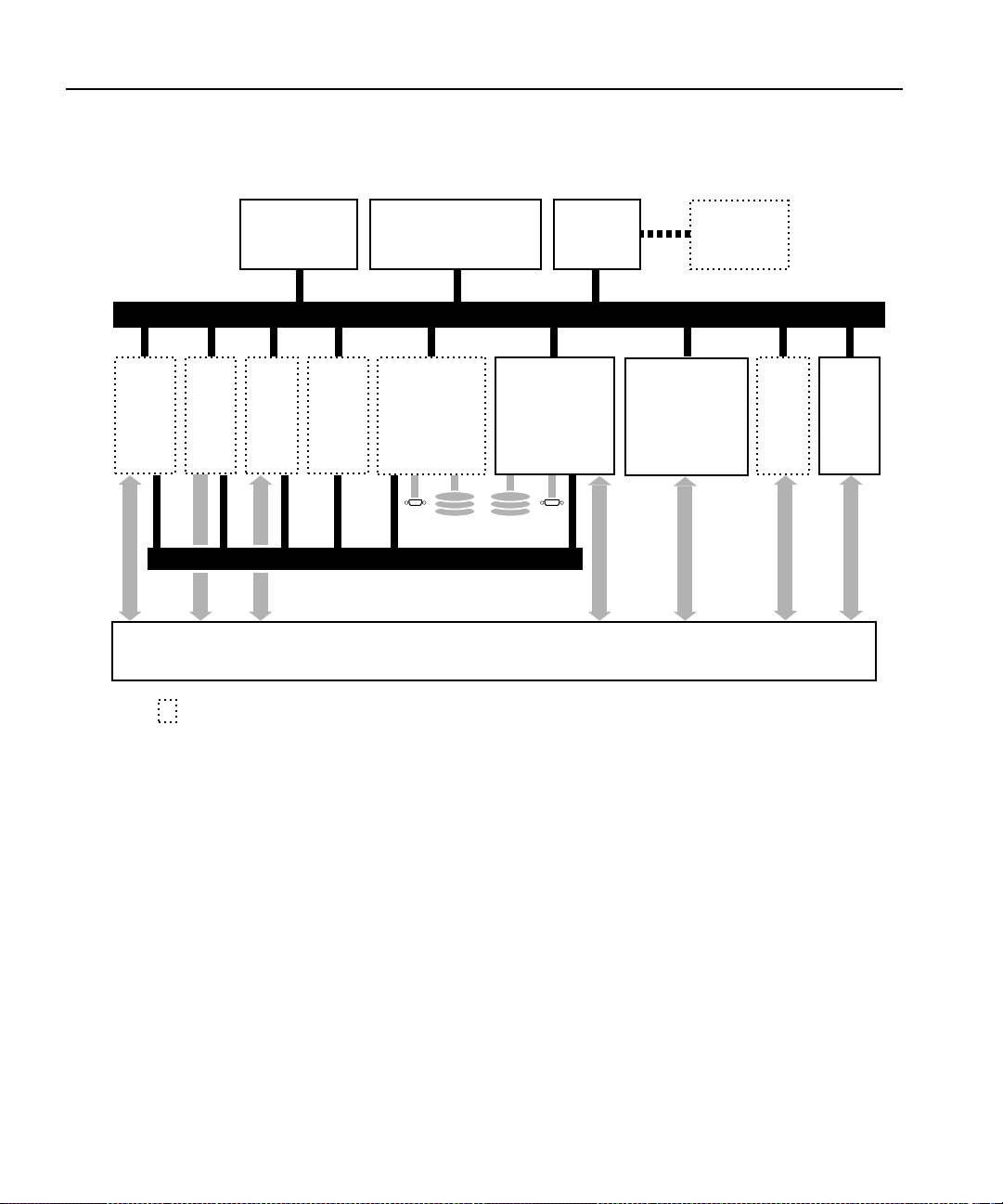
Video and Audio Interface Boards
DVCPRO
Codec
Networking
• RS-422 ports(8)
• Ethernet LAN I/O
MPEG
4:2:2
Decoder
only
MPEG
4:2:2
Encoder/
Decoder
Fibre
Channel
Arbitrated
Loop
Indicates optional board
Applications Processor
Subsystem
•
Intel Pentium Processor
Enhanced
Slave Recorder
• 2 JPEG CODECs
• Ultra SCSI-2
SCSI Devices
PCI Bus
32 x 32 CCIR 601
Video Router and Clocks
EISA Bus
Enhanced
Master Recorder
• Intel i960 real-time
processor
• 2 JPEG CODECs
• Ultra SCSI-2
Digital
Audio I/O
Analog
Audio I/O
(External Chassis)
Video I/O
• Analog Composite
• SDI w/Embed. Audio
• Comp. Analog In
• Analog Comp. mon.
Mix
Effects
Ref.
Genlock
Board
Clocks
9955-1
Figure 1. The PDR200/300 b l o ck diag ram
Profi le Fami l y 27
Page 28

Chapter 1 Introducing the Profile Family
Profile Software Development
The Profile Software Devel opment Kit (SDK) provides an application
programming inte rface (API) for libr arie s of P rofile func tions. We rec ommend
that you call these functions via Microsoft Visual C++ 5.0; however, it is
possible to use other langua ges that permit calls to C declared functions
(contact your Grass Valley Group representative for more information).
Software developers can use the API to control the Profile from third-party
hardware devices, for example. The API consists of seven libraries:
• The TekCfg library provides an interf ace to the Profile configuration.
• The TekPdr library furnishes calls that inventory and manage movies in
Common Movie Format (CMF), an internal file format standard for video,
audio, and timecode.
• The TekRem library makes it possible for a remote Windows NT syste m to
control a Profile disk recorder over an Ethernet LAN.
• The TekVdr library provides an inter fac e for playing and recording video
and audio clips.
• The TekVfs library suppor ts low-level ac cess to individua l media files i n the
media file system.
• The TekVme library controls the optiona l video mix effects board.
• The TekXfr library supports media stre aming of Fibre Channel connecti ons.
Eight RS-422 se rial ports come standar d on a disk re corder. A dis k recorder can
issue serial commands or receive them from an external device via RS-422
communication lines. The Profile Protocol associates each API call with a
specific number that can be sent over an RS-422 line. The ProLink app lication
monitors Profile Protocol calls over an RS-422 link, allowing you to use
compatible hardware devices, such as the PRC100 Control Panel, to issue
commands to a Profile unit.
Windows applications are also available to control the Profile system. Your
disk recorder comes with several standard and optional applications. See
“Starting and Closing Profil e Applications” on page 31 for more information.
NOTE: Louth and Odetics RS-422 protocols are also supported,
although th ere i s not a one-to-one co rre spondence be tween these
protocols and the Profile API. Louth and Odetics protocols do not
allow you full access to the functionality of the Profile system.
28 Profi le Fami l y
Page 29

What to Read First
The order in which you shoul d read the chapters of this manual d epends on how
you want to set up your Profile system.
• Before using you r Profile u nit, you must first configure your video and a udio
boards. Refer t o Cha p te r 2, “Using the Profile Configuration Manager.”
• If you are upgrading a PDR100 to version 2.5 of Profile system softwar e
from version 1.4.XX or earlier , you mus t install enhanced disk recorder
(EDR) boards and you must rebuild your file system. To install the EDR
boards, you must i nstall a fie ld kit that i s sold separa tely. To rebuild y our file
system, refer to Chapter 5, “Using the Profile Disk Utilit y.” Your file system
may consist of internal disks, a disk expansion unit, or a RAID unit.
• Once you have configured your video and audio boards, and, if necessary
rebuilt your f ile sy stem, you a re rea dy to capture a nd rep lay video a nd audio
clips. Refer to Chapter 4, “Using VdrPanel.”
• To configure your Fibre Channel board, see Chapter 7, “Fibre Channel
Video Networking.”
• To read Profile logs, acc ess your Prof ile syst em from a re mote PC, or atta ch
a PRC100 Profile Control Pane l, refer to Chapter 6, “Using Profile Utiliti es.”
What to Read First
• To learn how to manage media on disk or over Fibre Channel on a Profile
network, see Chapter 3, “Using Media Manager.”
• If want to use opti onal s oftware appl icat ions, s ee Chapter 8 , “Using the Tool
Box Editor,” Chapter 9, “Using the List Manager,” or Chapter 11, “Using
TimeDelay.” To allocate resources for Tool Box Editor, List Manager, and
TimeDelay, see Chapter 10, “Using the Resource Manager.”
Profi le Fami l y 29
Page 30

Chapter 1 Introducing the Profile Family
Starting Your Profile System
Once the unit is properly installed, you are ready to log in. For instructions on
how to install and power-on a PDR100, PDR200, or PDR300 see the
installation manual that came with the unit.
To log in automatically:
Power up the Profile unit , and the start up routine begins. Dur ing normal start
up, you are logged in automati cally and the VdrPanel ap plication st arts. You
can hold down the
process.
NOTE: If you stop the aut omatic log in, or if it fails, t he Windows NT
log in dialog box appears. When logging in, remember that this
dialog box is case-sensitive.
To manually log in:
Shift key during start up to interrupt the automatic log in
1. At the Windows NT 4.0 log in window, enter the username:
(However, you must log in as administrator when installing software,
performing Windows NT administration, starting a service, or setting an
Ethernet IP address.)
2. Use the Tab key to advance to the password field.
3. The password app ea rs as aste ris ks (* ) for pa sswo rd secu ri ty . For the
password, enter:
4. Use the Tab key to advance to the From field.
5. If your domain name or local computer name is not displayed in the box,
click in the box to access a list of choices. Sele ct your domain or local
comp uter na me from th e list.
6. Click
OK or press Enter.
NOTE: If a log in error message appears, and all the information is
correct, try deleting the password and clicking
profile
OK.
profile
30 Profi le Fami l y
Page 31

Starting and Closing Profile Applications
Starting and Closing Profile Applications
After logging into your Profile system, you see shortcut icons for the Profile
applications on the Windows NT 4.0 desktop.
Figure 2. PDR Application short cuts on the Windows NT 4.0 desktop
Profi le Fami l y 31
Page 32

Chapter 1 Introducing the Profile Family
Starting an Application
To start a Profile applica tion—VdrPanel in these exampl es —using Windows
NT 4.0:
• Double-click the shortc ut icon on the Windows NT desktop.
Or:
• Choose
Or:
• Choose
To start a Profile applica tion such as VdrPanel using Windows NT 3.51:
1. In Program Manager, double-click the PDR Applications program group
icon.
2. Double-click the
Start | VdrPanel.
Start | Programs | PDR Applications | VdrPanel.
VdrPanel icon in the PDR Applications program group.
Viewing Help
To view the Help for an application:
• Choose
Or:
• Click the
To view version information (for VdrPanel in this example):
• Choose
Help | Help Topics.
Help button in a dialog box or a toolbar, if available.
Help | About VdrPanel.
Closing an Application
To close Profile applications:
• Choose
32 Profi le Fami l y
File | Quit, File | Exit or click the Close button.
Page 33

Closing an Application
Profile Configuration
Manager
The Profile Configuration Manager
is a graphical user inte rfa ce fo r
configuring reference genlock,
system timing, video and audio
inputs and outputs. For more
informatio n, ref er to Ch ap ter 2,
“Using the Profile Configuration
Manager.”
NOTE: You must configure system resources with Configuration
Manager befo re usin g you r Pr ofile d i sk reco rd er .
Media Manager
The Media Manager allows you to manage
clips and masters on disk, transfer media
between syst em s , and arch i ve an d rest ore
clips on a l ibrary system . Refer to Chapter 3,
“Using Media Manager.”
Transcode Utility
The Transcode Utility, which is started from
Media Manager, convert s motion JP EG media to
MPEG or from MPEG to JPEG. You can also
change the video quality of a clip. Refer also to
Chapter 3, “Using Media Manager.”
Profi le Fami l y 33
Page 34

Chapter 1 Introducing the Profile Family
VdrPanel
VdrPanel enables you to capture and
trim video and audio clips and then
play them back. By default,
VdrPanel starts automatically when
you power-on your Profile system.
For more infor mat i on , refe r to
Chapter 4, “Using VdrPanel.”
Profile Disk Utility
As shipped from the factory, Profile
media disks come preformatted and
with a file system al rea dy created.
Profile Disk Utility allows you to
create new file s ystem s , ref or ma t
disks, and change di sk labels. To find
out more about how to use this
utility, refer to Chapter 5, “Using t he
Profile Disk Utility.”
NOTE: Locked versions of the following optional appli cations—Tool
Box Editor, List Manager and TimeDelay —were shipped t o you w ith
version 2.5 system software. You can use the software for a limited
time only. Unlocking this software for permanent use requires an
additional purchase. Click Purchase in the timelock dialog box for
information on how to purchase this software.
34 Profi le Fami l y
Page 35

Tool Box Editor
The optional Tool Box Editor lets you
create new media by logging and
capturing video and audio clips while
also providing an inexpensive, cutsonly editing system. Refer to Chapter
8, “Using the Tool Box Editor.”
List Manager
The optional List Manager allows you
to set up simple station automation.
You can record incoming video at
predetermined times, send incoming
video direct ly to a n out put, or combine
all of these functions to increase the
automation level of you operations.
Refer to Chapter 9, “Using the List
Manager.”
Closing an Application
TimeDelay
TimeDelay allows you to delay incoming
video by an amount of time you specif y. F or
more information, see Chapter 11, “Using
TimeDelay.”
Profi le Fami l y 35
Page 36

Chapter 1 Introducing the Profile Family
Profile Utilities
• Profile Logs allow you to view Profile syste m logs with the graphical log
viewer, WinTail. This log viewer allows you to see the end of a log file. To
learn more about how to view Profile logs, see Chapte r 6, “Using Profile
Utilities.”
• ProLink monitors Profile Prot ocol calls over RS- 422 communicati on lines,
allowing you to use a controller suc h as the PRC100 Control Panel to
communi cate w i th a Profi le syst em . For mo re info rm at i on on Pro file
Protocol, see the documentation that accompanies the Profile Software
Development Kit.
• PortSever allows you to control a Profil e unit remotely using Ethernet
communications. For example, you can run PortServer on a remote Profile
system so that you can control it over a LAN from another Profile or PC.
PortServer is generally used in conjunction with Fibre Channel operations.
• PDR Access Control is a Windows NT service that preve nts one application
from crashing another appli cation by mistake. Though large ly transparent to
users, the ser vice prevents applicati ons from accident ally reloading the vi deo
processor while in use, essentially providing a controlled gateway to the
processor.
• Update Firmware re programs components on boards in your PDR200
Video File Server, such as the Master Enhanced Disk Recorder (EDR) board.
Updating the firmware in the selec ted components of these boards ensures
that software and hardware will function together as expected.
• Update Fibre Channel Microcode upda tes the microcode on Fibr e Channel
boards.
Fibre Channel Support
You can use Fi bre Channel video ne tworking capabilitie s to move media fr om
one Profile unit directly t o another . With Media Manage r, you can use the Fibre
Channel connection to transfer media files between machines. Ethernet LAN is
also require d for tran s fer ri ng com mands and statu s inf ormation. For m ore
informatio n, s ee Chap t er 7, “Fibre Channel Video Networking.”
36 Profi le Fami l y
Page 37

Chapter
2
Using the Profile Configuration Manager
The Profile Configuration Manager provides an easy-t o-use interface that
streamlines the set up of refe rence ge nlock, video a nd au dio i nputs an d out puts,
system timing, and timecode for your Profile video disk recorder. The
configuration tree allows you to open the specific configuration dialog boxes
that control the setting s. A graphic representa tion of the Profile rear panel at the
bottom of the Configuration Mana ger window shows which boards are
installed. The Configuration Manager window appears in Figure 3.
Toolbar
Configuration tree
Profile rear panel representation
Figure 3. Profile Configuration Manager window
Profi le Fami l y 37
Page 38

Chapter 2 Using the Profile Configuration Manager
To select an item from the configuration tree:
•²The configuration tr ee app ears on the left side of the window. Clicking on
an entry, such as
expanded list of choices, su ch as if you click on
collapses the list of choices.
•²A single click opens the specific dialog box, closing a previously opened
box, if necessary. A double-click opens the sp ecific dialog box but does not
close any other open dialog boxes . To clos e all open dialog boxes at once,
choose
Window | Close All.
Video Input , e xpands the list of choices. Clicking on an
Video Input a second time,
All changes in a dialog bo x take plac e immediately. The
Undo button will undo
changes from t he time a dialog b ox was opened in the c urrent tab of t he dialog
box. The
Undo button is dimmed if there is nothing to undo. The Help button
opens context-sensitive help related to the current dia log box.
By default, the toolbar and status bar are shown in the Configuration Manager
window. To hide the toolbar or status bar:
• Choose
View | Toolbar or View | Status Bar.²
To view information about inst alled boards:
• Choose
Help | Installed Boards Information.
38 Profi le Fami l y
Page 39

Saving a Configuration File
It is possible to preserve a conf iguration for later use. You can save your current
overall configur ation in a file and then load it later. Configurat ion files have a
.cfg extension. To save your current configuration in a file:
Saving a Configuration File
1. Choose
(Figure 4).
2. Enter a file name in the File Name box—new.cfg in this example.
3. Press Enter or click
File | Save Current Configuration. The Save As dialog box appears
Figure 4. Save As dialog box for saving a configuration file
Save. The curr ent configu ration is saved.
Profi le Fami l y 39
Page 40

Chapter 2 Using the Profile Configuration Manager
Loading a Configuration File
To load a configuration file that has been saved previously:
1. Choose
(Figure 5).
2. A message box warns you that if you load a configuration file, all open
windows are cl os ed . Click
3. Double-click a file name in the tree or type the name of the file in the File
Name box—new.cfg in this e xampl e .
4. Press Enter or click
File | Load Configuration File. The Open dialog box appears
Figure 5. Open dialog box for loading a configuration file
Yes to continue.
Open. The file is loaded as the current confi guration.
40 Profi le Fami l y
Page 41

Setting Master Timecode
From the Master VITC Setting dialog box, you can conveniently view and
change VITC settings for genloc k and all available inputs and outputs. To set
the master timecode (VITC) settings:
Setting Master Timecode
1. Choose
the toolbar. The Master VITC Setting dialog box appears (Figure 6).
Option | Master Timecode or click the Master Timecode button on
Figure 6. Master Timecode dialog box, genlock settings
Profi le Fami l y 41
Page 42

Chapter 2 Using the Profile Configuration Manager
2. The VITC Present status indicator should be on (green) if VITC is present.
If VITC Present is not on, use one of the following options:
•²Manual VITC detect ion (four-channel LTC versi on of the reference genlock
board):
- Verify Automatic VITC detect is not selected. If it is, click to toggle it.
- Set VITC Reader Line1 to the expected location of the first Reader Line
and VITC Reader Line2 to the second expected Reader Line. If y ou only
have one VITC line, enter the same value on both Reader line s.
- Check VITC Present. If it is still not on, use a waveform monitor to check
the genlock signal to make sure that VITC exists on these lines.
•²Automatic VITC detectio n only:
- Verify Automatic VITC detect is selected. If it is not, click to toggle it.
The Search Lines are automatic ally established for NTSC/525 and
PAL/625.
- Check VITC Present. I f it is still n ot on, che ck the ge nlock signal to ma ke
sure that VITC exists and is within the expected range.
3. For each video input that should have VITC, select it from the list:
•²For automatic VITC detection on analog composite and serial digital
component signals:
- Verify Automatic VITC detect is selected. If it is not, click to toggle it.
- Set VITC Reader Li ne1 to t he beginn ing of t he se arch line. The minimu m
- Check for VITC Present.
•²For manual VITC detection on analog compos ite and serial digital
component signals:
- Verify Automatic VITC detect is not selected. If it is, click to toggle it.
- Set VITC Reader Line1 and VITC Reader Line2 to the lines where VITC
- Check VITC Present. If it is still not on, double c heck your line numbers
42 Profi le Fami l y
line number is 6 in PAL and 10 in NTSC.
is located. If you only have one VITC line, enter the same value on both
Reader line s.
and try again.
Page 43

Setting Master Timecode
4. For each video output that should have VITC, select it from the list:
• For analog composite on preexisting P DR100 and PDR200 units:
- Verify VITC Generator Enable is checked. If not, click to toggle it.
- Click on Vert. Interval to open the Vertical Interval Line Programming
dialog box.
- Select the desired VITC l ines by checki ng in the VITC Enable colu mn for
the line. There is not a limit on the number of VITC lines.
- Click
Close to close the Vertical Interval Line Programming dialog box.
•²For serial digital component:
- From the Serial Digital C omponent Video Output d ialog box, se t the lines
where you want VITC in VITC Generator Line1 and VITC Generator
Line2.
- Verify VITC Generator Enable is checked. If not, click to toggle it.
Profi le Fami l y 43
Page 44

Chapter 2 Using the Profile Configuration Manager
Setting the System Timing
A new, factory-default PDR200 or PDR300 is configured so that:
• All outputs are zero-timed to the external reference (house black).
• Each input can loc k to and record any stable video input, whether or not the
source is genlocked to an external reference.
NOTE: Serial digital inputs (525 lines) on a PDR100 must be timed
manually.
To adjust system timing:
1. Choose
toolbar. The System Timing dialog box appears (see Figure 7 which shows
an example of how the dialog box look s when the outputs are zero-timed by
default).
- The red line represents the external reference, and the yellow line
- A hashed box represents a t iming windo w or, i n other words, the ra nge of
- The external reference, represented at the top of the dialog box, shows a
2. Click any button to the left of the internal refe rence (genlock) or video output
signal name and the timing edit box a ppears i n the bot tom left of the Syst em
Timing dialog box (see Figure 8 which shows the dialog box whe n the
outputs are E to E timed).
3. In the timing edit box, you can adjust the number of fields (ge nlock only) or
lines, and also tune these settings with course or fine adjustments. You can
enter a number directly or click an arrow to adjust a setting. The adjustments
and ranges available var y, de pending on the type of output you have.
4. Click
Default to return to the default settin gs.
Option | System Timing or click the System Timing button on the
represents reference genlock.
lines within which the timing is adjusted.
range from –16 to +16 lines. You can scroll past this r ange by dragging
the pointer on this line in eithe r dire ction with the mouse.
Close to accept the setti ngs, Undo to return to the previous settings,
NOTE: You must restart your unit for the new system timing s etting
to tak e effe ct.
44 Profi le Fami l y
Page 45

Setting the System Timing
You can also fine tune your system timing settings individually under
Reference Genlock System Input Advanced Adjustment in the Reference
Genlock dialog box. You can also tune in dividu al output se ttings unde r Output
Timing Adjustment in under Video Output .
Figure 7. System Timing dialog box, zero-timed
Profi le Fami l y 45
Page 46

Chapter 2 Using the Profile Configuration Manager
E to E Timed Outputs
In some applications, you may want to precisely switch an output from a live
video feed to playback of recorded materi al. Since the live input will be delayed
as it pass es through the Pro file unit, you must set a corresponding delay on the
playback. The E to E Ti med Output opt ion sets a 16-line delay on all the system
outputs, allowing a zero-timed input to be exactly timed with a play to air
signal. To set all your Profile unit output for E to E operations:
1. Choose
Option | System Timing or click the System Timing button on the
toolbar. The System Timing dialog box appears.
2. Click
3. Click
E to E Timed Output.
Close.
46 Profi le Fami l y
Figure 8. System Timing dialog box, E to E timed
Page 47

Adjusting the Timing when Upgrading to 2.5
Adjusting the Timing when Upgrading to 2.5
If you are upgrading an existing PDR100 to system software version 2.5, your
system timing will be left in E to E mode and no chang es will be made to yo ur
system timing. The only diff erenc e you wil l s ee is a numeric of fse t of 7 li nes in
the Line setting und er Refe rence Genlo ck System Input Advanc ed Adjustm ent
in the Reference Gen lock dialog box and an offset of n ine lines in the Vertical
Line Delay under Output Timing Adjustme nt under Video Output.
Auto Timing
Auto-timing determines if the input is synchronized to the reference genlock
signal. The disk rec order r ecords time -base corre cted vide o whether or not it is
also locked to the re ference. If auto- timing is enable d and the signal was ab le to
be timed into the system, the
dialog box is turned on.
If you want to use t he disk recorder as a swit cher and/or have the output v ideo
correctly timed when in E to E mode, the input video must be locked to the
reference and properly ti med to the disk re corder. To aid in the timing se tup, all
video inputs have auto-tim ing circuits which synchronize input video to the
internal timing refe rence as long as the input video is within the auto-timing
sync window (±2 lines for the latest analog composite boards, ±1 lines for all
others). To get to the auto- timing window, input must be advanced 7 1/2 lines.
Auto T i m ed ind ic ator a t t he to p of the vi deo in put
The auto-timing cir cuit is always trying to lock to the signal. If you try to auto
time a signal outside of the window, the video signal appears to be broken-up
as it cannot be timed into the s ystem. If the i nput dri fts out of r ange, it i s retim ed
as soon as it drops back into range. The disk recor der can use untimed signals
if auto-timing is not enabl ed, but they are not timed correctly and may cause
jumping and skipping in E to E mode.
NOTE: If you select auto-timing for an input sig nal and it cannot
auto time with the genlock referenc e signal, the input signal is not
recorded accurately. If you must record an input that cannot lock,
disable auto timing and then record. There may be problems if you
are operating in E to E mode, but the clip plays back correctly timed.
If auto-timing is enabled, and the signal was able to be timed into the system,
the Auto Timed indi cator i s tu rned on. Also, for serial digi tal compo nent inpu t,
Line 1 can still be adjusted, but Line 2 is always equal to Line 1 + 14.
Profi le Fami l y 47
Page 48

Chapter 2 Using the Profile Configuration Manager
Setting the Reference Genlock
The Reference Genlock dia log box sets the genlock para meters for VITC reader
settings and intern al reference timing. At the top of the dialog box, the status
indicators displa y the current status of the genlock input: Locked to External
Reference, Internal Clock Locked and VITC Present. A green light indicates
that a particular status is on. These indicators cannot be edited.
To change the reference genlock settings:
1. Click or double-click
Genlock dialog box appears (see Figure 9).
2. Click Automatic VITC Detect to have the Prof ile disk recorder use the range
set in the
signal. If the VITC signal is found, the VITC Present indicator is turned on.
Otherwise, when you do not use Automatic VITC Detect, the disk recorder
expects to find t he VITC signals on VITC Reader Line 1 (default 10) or Line
2 (default 12).
From and To lines to look for the VITC (verti cal inte rval timec ode)
Genlock from the configuration tree and the Reference
Figure 9. Reference G enlock dialog box
48 Profi le Fami l y
Page 49

Setting the Reference Genlock
3. Use the Field, Line, and Fine entries t o adjust the internal timing relative to
the reference inp ut. Changing this sett ing affects all syst em timing, includin g
all output timing and the input synchr onized timing window. Click
to return to the default timing values (0,0,0).
NOTE: In order to properly time the disk recorder, the Internal
Reference Timing shou ld only be changed if the downstream timing
requirements cannot be met using the vide o output Timing
Adjustment (see “Video Output” on page 67). This should be done
prior to setting indivi dual output delay adjustments.
Default
4. Click
Undo to return all values in t he dial og box as they were set at the ti me
the dialog box appeared.
5. Click
Close to accept the changes.
Profi le Fami l y 49
Page 50

Chapter 2 Using the Profile Configuration Manager
Changing LTC Input and Output Names
The LTC (longitudinal timecode) inputs an d outputs dialog box allows you to
rename the LTC inputs and outputs.
To change an LTC name:
1. Click or double click
Input & Output dialog box appears.
1. Select an LTC input or output name.
2. Position the edit cursor within the appropriate edit box.
3. Enter the new name or portion of a name.
4. The new name appears in the name list.
5. Click
Undo to return the name or names as they were at the time the dialog
box appeared.
LTC In put & Ou tput in the configur ation tree and LTC
Figure 10. LTC Inputs & Outputs dialog box
6. Click
50 Profi le Fami l y
Close to accept the new LTC name or names.
Page 51

Setting MPEG Input Timing
If you have one or more MPEG board(s) insta lled that have decoders only (no
encoders) and you are running in BVW [insert edit ] mode (see “Setting up
BVW [insert edit] Emulation” on pa ge 172), y ou nee d to obta in a ti ming signa l
from a video I/O board to synchronize your output.
To select a timing input for the MPEG board:
Setting MPEG Input Timing
1. Click or double-click
Timing Selection dialog box appears (see Figure 11).
2. In the Input Timing box, select the board from which you want to get the
timing signal.
3. Click
Undo to return to original input timing source.
MPEG Board from the configuration tr ee and the Input
Figure 11. MPEG Input Timing dialog box
4. Click
Close.
Profi le Fami l y 51
Page 52

Chapter 2 Using the Profile Configuration Manager
Video Input
You may have analog composite, component analog (CAV), or serial digital
component video inpu ts installed in your Profile s ystem. The steps to conf igure
video inputs follow.
Analog Composit e Video Input
The indicators at the top o f t he dialog box show the curr ent status of t he analog
composite video input. The indicators are
Auto Timed (also Burst Present for earlier analog composite cards). A green
light indicates tha t a status is on. These are indicators and cannot be edite d.
To configure analog composit e video input:
VITC Present, Input Locked , and
1. Select
click an analog composite input from the list, such as Composite-InA-J5. The
Analog Composite Video Input dialog box a ppears (Figure 12 for current
analog composite cards and Figure 13 for earlier cards).
Video Input from the configuration tree, and then click or double-
Figure 12. Analog Composite Video Input dialog box, Main tab (A)
52 Profi le Fami l y
Page 53

Analog Composite Video Input
Figure 13. Analog Composite Video Input dialog box, Main tab (B)
2. If you prefer, enter a new name for the input signal in the Name box. For
example, if the signal is a network feed, you could rename it to
Network_Feed. The VITC name, the wind ow title bar, and t he configur ation
tree name chan ge au tom at ical l y as yo u enter t he new name. Names can be
up to 30 cha racters, and can include spaces. To return a renamed s ignal to th e
default, delete all the characters in the text field, and press Enter.
3. Select a video standard. Click either
pedestal
, or PAL (PAL is available only with earlier cards). If you change
NTSC with pe destal, NTSC without
the standard, resta rt all tools that use this channel . The board can accept only
one input at a time.
4. If you use Automatic VITC Detect, the Profile unit uses the range set i n the
From and To lines to look for the VITC signals. If Automatic VITC Detect
is not checked, the system expects to find the VITC signals on the VITC
Reader Line 1 (default 10) or Line 2 (default 12). If the signal is found, the
VITC Present status indicator is turned on.
NOTE: Input must be auto-timed to use automatic VITC detection.
Profi le Fami l y 53
Page 54

Chapter 2 Using the Profile Configuration Manager
5. If you want video input auto tim ed, click Enable Auto-Timing. Auto-ti ming
determines if the input is synchronized to the refer ence genlock signal. The
disk recorder records time-base corrected video whether or not it is also
locked to t he reference. If a uto-timing is enable d, and the signal was able to
be timed into the system, the
information on auto timing, see “Auto Timing” on page 47.
Auto Timed indicator is turned on. For more
6. Click
Enable Dithering if the incoming signal is 10-bit resolution. This
produces the b est quality result. The LSB artifacts on 10-bit video f eeds are
reduced. The re is n o effect if the inco m i ng sign al is 8-b it.
7. Click
Vertical Blanking to enable vertical blanking. When enabled, for the
525 standard, lines 1 throu gh 9 and 264 through 272 are blanked; fo r the 625
standard, lines 1 through 5, 311 through 317, 624, and 625 are blanked.
8. Adjust the input gain on the syncs to compensate for any losses in the input.
You can adjust the gain manually or, with earlie r cards, click
AGC
(Automatic Gain Control) which enables the internal quality monitoring
circuit to automati cally adjust the gain to keep the sync level constant. To
adjust the gain manually, move the slider to the desired value. The range is
from 71 to 141 percent (±3 dB) of the input signal. (For earlier cards, the
range is from 45 t o 142 percent ( ±3 dB) of t he input si gnal f or NTSC and 82
to 142 p ercent for PAL.) When you c lick
Default, the Input Gain Adjustment
resets to the default val ue (100 perc ent).
9. Click
10. Click
Undo to return the values in the dialog box to their original settings.
Close to accept all inputs.
54 Profi le Fami l y
Page 55

Analog Composite Video Input Advanced Control
Analog Composite Video Input Advanced Control
The Advanced Control tab allows you to sele ct a decode mode, clam p speed,
and other settings, depending on which analog composite card you have. To
change advanced controls settings:
1. Click or double-click on the
shows the dia log box for the most recent analog compos ite video car ds while
Figure 15 shows the dialog box for earli er car ds).
Figure 14. Analog Composite Vide o Input dialog box, Advanced Control t ab (A)
Advanced Control tab to view it (Figure 14
Profi le Fami l y 55
Page 56

Chapter 2 Using the Profile Configuration Manager
Figure 15. Analog Composite Vide o Input dialog box, Advanced Control t ab (B)
2. Click a setting for decode mode. Decode mode determines how the
chrominance and luminance information is separated for convers ion for
storage. There are three options for the current analog composite cards and
four options for the earlier cards:
- ²
- ²
56 Profi le Fami l y
Notch Filter . Decode mode separates the chrominance by using a notch
filter around the chromina nce subcarrier. This leaves the high frequency
luminance intertwi ned with the chrominance. A notch decoder readily
determines hori zontal lines are line-to-line luminance . F ine vertical li nes
can be more diffi cul t.
Comb Filter. Decode mode tries to separate high frequency luminance
from the chrominance using the same notch filter a s the notch decoder, but
also takes information f rom the next line. It uses this information to
determine if high freque ncy is luminance or chrominance. A comb
decoder readily determines finely spaced vertical li nes are luminance. A
lack of line-to-li ne phase alteration causes difficulty with fine horizontal
lines.
Page 57

Analog Composite Video Input Advanced Control
- ²Spatial Adaptive. Decoding uses either the c omb or notc h decoder, on a
pixel by pixel basis, depending on which gives the best results. For
horizontal lines , notc h is used; for vertical lines, comb is used.
NOTE: Spatial adaptiv e and temporal/spati al adaptiv e decoding uses
the high or low threshold setting.
- ²
Temporal/Spatial Adaptive. This is for earlier analog composite cards
only. Decoding uses both the next line and the same line in the alternate
field in the calculations. This decoder uses all of the properties of the
Spatial Adaptive decode r, plus it uses Temporal (interfield changes)
information. The phase change (or lack of) from field to field helps
determine whether hi gh frequency should be decoded as chrominance or
luminance. The threshold determines the amount of motion allowed
between alternate fields to still have the Temporal decoder recognize the
pixel. High allows more motion than Low.
3. For the current analog c omposite card, c lick
Enable Clamp Speed to enable
it. Clamp speed sets the reaction to changing DC levels of the input signal.
Speed can be either slow or fast. The fast cla mp speed is more reactive to
small DC variations. The slow speed ignores short-term DC level changes
but gradually changes the cl amping le vel to track the input.
For clamp speed on earlier cards, click
under the Clamp Speed group.
Fast and Slow setting s are the same for both
the earlier and current cards, while
and
Slow. Adaptive uses the best clamp for the current video input. Clamp
Adaptive, Slow, Medium, or Fast
Medium is a compromise between Fast
Speed also helps with white noise reduction. Adaptive is the best choic e for
white noise reduction. Do not use Adaptive for impulse noise, use Slow and
the Impulse Noise Detectio n option from the Noise Reduction group.
NOTE: If you set AGC (audio ga in control) to aut omatic on the main
screen, clamp speed cannot be select ed.
4. For current anal og co mpo s ite card s, the Ve r tica l Int erval co ntr o ls set ho w
vertical i nterval sig nals ar e handle d. Move t he Group Def init ion slide r t o set
how many lines are in Groups 1 and 2. In Group 1, Notch and Pass are
available while Blank and Pass are avai lable in Group 2:
-
Notch applies notch filtering to the vertical interval video line. This
means that chrominance infor mation and any luminance around the
chroma subcarrier are removed.
Profi le Fami l y 57
Page 58

Chapter 2 Using the Profile Configuration Manager
- Pass indicates that the vertical video line is passed- through.
Blank indicated that line the grou p are blank.
-
5. Under Noise Reduction (earlier analog composit e cards only) , the controls
enable and set various noise reduction methods:
- Click ²
Enable Luma and Chroma Reduction. This applies t he Level a nd
Threshold settings to use a feedback noise reduction scheme on the
decoded input signals after they have been separated into chrominance
and luminance. The Le vel a nd Threshol d sli ders d etermi ne the amount of
weight the feedback signal has in compar ison to the input signal. The
Threshold range takes into c onsideration the amount of motion in the
picture. Use the s lid er s to adju st the ranges. Be sure Ena ble Luma and
Chroma Reduction is checked for the reduction values to be applied.
- Click
Enable Quiet Line, if desired. This acts as a noise reference. If the
Quiet line is noise -fre e, t he res t of the sign al should also be noise-free.
This allows the decode r to no t mista ke nois e for m otion. If t he Quie t Line
is ena b l ed, t he li n e va lu e s f or Fi el d 1 and Fi eld 2 are u se d. U s e the sl id ers
to set the line values for each field. Click on
Default Lines to return to the
default values.
Enable Impulse Noise Reduction automatically filters out noi se spike s,
-
such as amplifier crackling.
NOTE: If reduction of impulse noise is selected, the disk recorder
automatically switches the clamp speed to slow. It is recommended
that you use the spatial adaptive decode option, although it does not
automatically switc h.
6. Click
Undo to return the values in the dialog box to their original settings.
7. Click
58 Profi le Fami l y
Close to accept all inputs.
Page 59

Analog Composite Video Input Time Base Correction
Analog Composite Video Input Time Base Correction
The Time Base Corre ction tab i s a vailable only on the newe r analog composi te
cards. To select the settings:
1. Click the
Figure 16. Analog Composite Video Input dialog box, Time Base Correct ion tab
TBC S e lection tab (see Figure 16).
2. When you sel ect Time Base Cor recti on , you can se lect eith er comp o site
input or Super VHS (SVHS or S-video) input. There are two channels
available for the most recent analog composite video input board. If Time
Base Correction is selected in channel A, channel B is unselected, and vice
versa.
3. Click Undo to return the values in the dialog box to their origina l settings.
4. Click
Close to accept all inputs.
Profi le Fami l y 59
Page 60

Chapter 2 Using the Profile Configuration Manager
Analog Composite Video Input Ver tical Int erva l
For earlier a nalog composite card s, the controls under the Vertical Interval tab
sets how the vert ical inte rval signals are handle d. This ta b is visible only i f you
have an older card in your Profile unit. For the most recent cards, the vertical
interval setti ngs are handled under the Advanced Control tab. There are
different vertical interval line numbers in the dialog boxes, depending on your
video standard—NTSC/525 or PAL/625. To change vertical interval set tings:
1. Click or double-click on the
Figure 17. Analog Composite Video Input dialog box, Vertica l In terval tab
Vertical Interval tab (see Figure 17).
60 Profi le Fami l y
Page 61

Analog Composite Video Input Vertical Interval
2. Move the sliders for each i ndividual line to se le ct Normal, Notch, Pass on
Y
, or Delete.
Normal indicates the vertical interval video line is passed-through.
- ²
Notch applies notch filtering to the vertical interval video line
- ²
(chrominance information and any luminance around the chroma
subcarrier are removed) .
Pass On Y passes luminance information st raight through. This is useful
-
for VITC and closed-caption or data filtering.
Delete removes the vertic al interval video line and replaces it with black.
-
3. Click
4. Click
5. Click
Undo to return the values in the dialog box to their original settings.
Default to return all values to their default values.
Close to accept all inputs.
Profi le Fami l y 61
Page 62
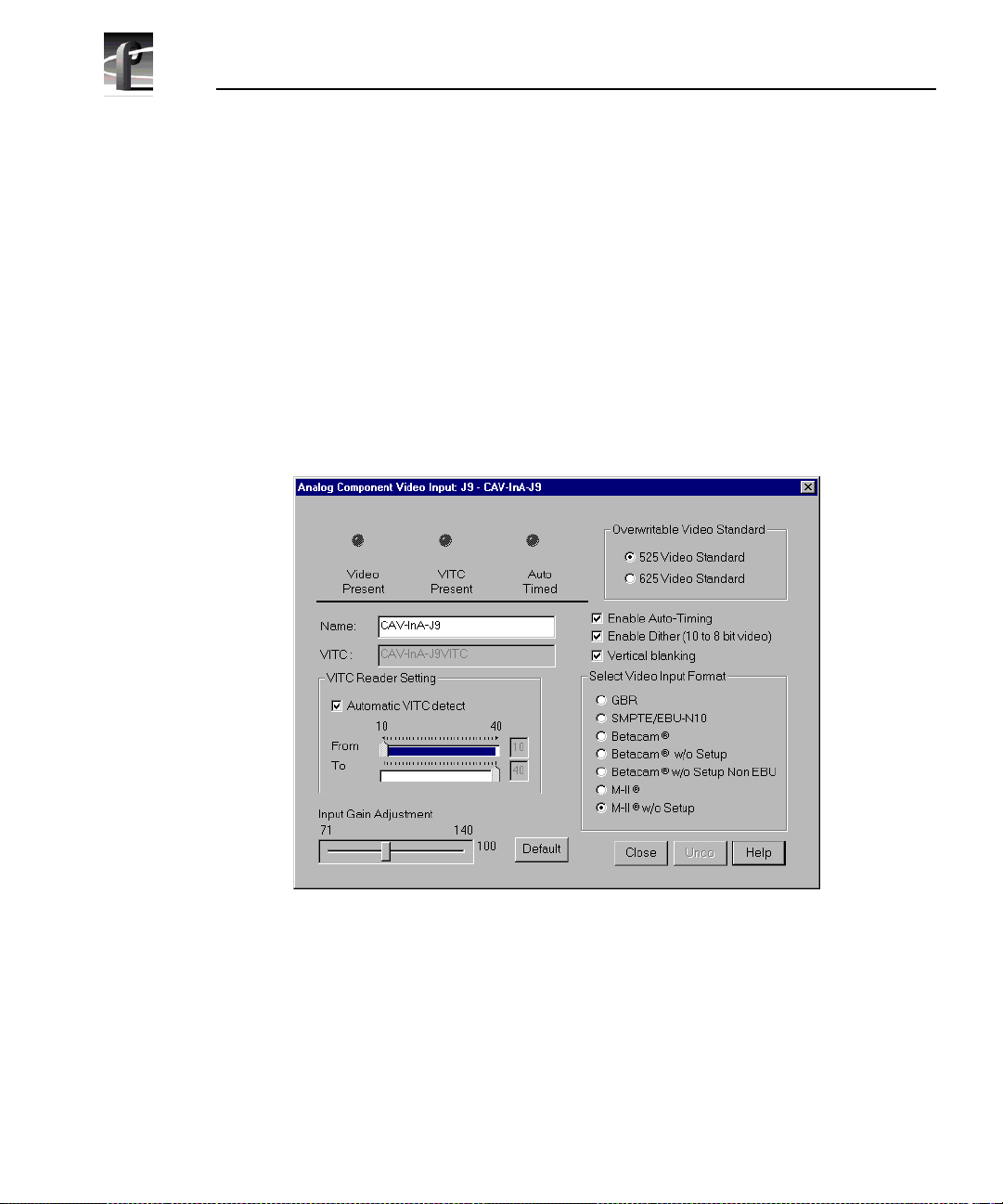
Chapter 2 Using the Profile Configuration Manager
Analog C om p on en t V ide o I np u t
You can configure analog component vide o (CAV) input with the Analog
Component Video Inpu t di alog box . The curre nt s tatus indica tors, shown a t th e
top of the dialog box, are
green light indicate s that a particular status is on. These indica tors cannot be
edited.
To configure analog component vide o input:
Video Present, VITC Present, and Auto Timed. The
1. Select
Video Input from the configuration tree, and then click or double-
click an analog component input from the list, such as CAV-InA-J9. The
Analog Component Video Input (CAV) dialog box (Figure 18).
Figure 18. Component Analog Video Input di alog box (CAV)
2. If you prefer, enter the new name in the Name box. For example, if the signal
is a Betacam input, you could rename it to Betacam_1. The VITC name,
window title bar name, and the configur ation tree name automatically
change as you enter the new name. Names can be up to 30 characters, and
can include spaces. To return a renamed signa l to the default, delete all the
characters in the text field, and press Enter.
62 Profi le Fami l y
Page 63

Analog Component Video Input
3. Under Overwritable Video Standard, click either 525 Video Standard or
625 Video Standard. If you change this sta ndard, you must restart al l tools
that use this cha nnel. The video input board can serve both standards , but the
input can only accept one at a time.
4. Select a VITC reader sett ing. If you to us e
recorder uses the range set in the
From and To lines to look for the VITC
Automatic VITC Detect, the disk
signals. If Automatic VITC detect is not used, the disk recorder expects to
find the VITC signals on the VITC Reader Line 1 (defaul t 10) or Line 2
(default 40). If the signal is found, the
VITC Present indicator is turned on.
NOTE: Input must be auto timed to use automatic VITC detection.
5. To change
Input Gain Adjust ment, move the slider to the desired value. The
range is from 70 percent to 140 percent (3 dB) for the input signal for both
525 and 625. When you click on
Default, the Input Gain Adjustment resets
to the default value (100 percent).
6. If you want video input auto tim ed, click
Enable Auto-Timing. Auto-timing
determines if the input is synchronized to the refer ence genlock signal. The
disk recorder records time-base corrected video whether or not it is also
locked to t he reference. If a uto-timing is enable d, and the signal was able to
be timed into the system, the
Auto Timed indicator is turned on. For more
information on auto timing, see “Auto Timing” on page 47.
7. Click
Enable Dithering if the incoming signal is 10-bit resolution. This will
produce the best quality result. The LSB artifacts on 10-bit video feeds are
reduced. The re is n o effect if the inco m i ng sign al is 8-b it.
8. Click
Vertical Blanking to enable vertical blanking. When enabled, for the
525 standard, lines 1 throu gh 9 and 264 through 272 are blanked; fo r the 625
standard, lines 1 through 5, 311 through 317, 624, and 625 are blanked.
9. Click an appropriate format under Select Video Input Format.
10. Click
11. Click
Undo to return the values in the dialog box to their original settings.
Close to accept all inputs.
Profi le Fami l y 63
Page 64

Chapter 2 Using the Profile Configuration Manager
Serial Digital Component Video I nput
You can configure ser ial digital component vi deo input with the Serial Digital
Component Video Inpu t di alog box . The curre nt s tatus indica tors, shown a t th e
top of the dialog box, are
green light indicate s that a particular status is on. These indica tors cannot be
edited.
To configure serial digital component video input:
Video Present, VITC Present, and Auto Timed. The
1. Select
Video Input on the configuration tree, and then cli ck or double-click
a digital component input from the list, such as SDI-InA-J13. The Serial
Digital Component Video Input dialog box appears (Figure 19).
Figure 19. Serial Digital Component Video Input di alog box
2. If you prefer, enter the new signal name in the Name box. For example, if
SDI-InA-J13 is a dedicated satellit e feed, you c ould re name it to Satellite_1.
The VITC name, window title bar name, and the configuration tree name
automatically change as you enter the new name. Names can be up to 30
characters, and can include spaces. To return a renamed signal to the default,
delete all the characters in the text field, and press Enter.
64 Profi le Fami l y
Page 65

Serial Digital Component Video Input
3. Under Overwritable Video Standard, click either 525 Video Standard or
625 Video Standard. If you change this sta ndard, you must restart al l tools
that use this cha nnel. The video input board can serve both standards , but the
input can only accept one at a time.
4. Select a VITC reader sett ing. If you to us e
recorder uses the range set in the
From and To lines to look for the VITC
Automatic VITC Detect, the disk
signals. If Automatic VITC detect is not used, the disk recorder expects to
find the VITC signals on the VITC Reader Line 1 (defaul t 10) or Line 2
(default 12). If the signal is found, the
VITC Present indicator is turned on.
Line 1 and Line 2 cannot be more than 14 lines apart.
NOTE: Input must be auto timed to use automatic VITC detection.
5. If you want video input auto tim ed, click Enable Auto -Timing. Auto-ti ming
determines if the input is synchronized to the refer ence genlock signal. The
disk recorder records time-base corrected video whether or not it is also
locked to t he reference. If a uto-timing is enable d, and the signal was able to
be timed into the system, the
Auto Timed indicator is turned on. For more
information on auto timing, see “Auto Timing” on page 47.
6. Click
Enable Dithering if the incoming signal is 10-bit resolution. This will
produce the best quality result. The LSB artifacts on 10-bit video feeds are
reduced. The re is n o effect if the inco m i ng sign al is 8-b it.
7. Click
8. Click
Undo to return the values in the dialog box to their original settings.
Close to accept all inputs.
Profi le Fami l y 65
Page 66

Chapter 2 Using the Profile Configuration Manager
Serial Digital Component Vide o Input Advanced
The Advanced tab a llows you to determine whether the EDH (Error Detec tion
and Handling) packet is present, which audio groups (1–4) are present, and
which errors are present: Full Field (FF) CRC or Active Picture (AP) CRC, plus
parity and checksum errors.
To reset EDH for serial digital video input:
1. Click the
Advanced tab to view the Serial Digital Component Video Input
Advanced settings.
Figure 20. Serial Digita l Component Video Input, Advanced
2. Click Reset FF CRC to reset Full Field errors or Reset AP CRC to reset
Active Picture errors .
3. Click
Undo to undo the resets.
4. Click
66 Profi le Fami l y
Close to exit.
Page 67

Vide o Output
You can configure either analog composite or serial digital component vide o
output on your Profile syste m, depending on which boards are installed.
Analog Composit e Video Output
To open the Analog Composite Video Output dialo g box:
Video Output
1. Select
Video Output from the configuration tree and click or double- click an
analog composite output from the list, such as Composite-OutA-J11. The
Analog Composite Video Output dialog box appears (see Figure 21).
Figure 21. Analog Composite Video Output dialog box
2. ²Enter a new name in the Name box to change t he signal name. For example,
if this is a dedicated signal to a main swit cher , r ename it Switcher_1. The
VITC Name automatically tracks the signal name and cannot be edited.
Names can be up to 30 characters, and can include space s. To retur n a
renamed signal to the default, delete all the characters in the text field, and
press Enter.
Profi le Fami l y 67
Page 68

Chapter 2 Using the Profile Configuration Manager
3. Click VITC Gene rator Enable to place VITC on specified lines in the
vertical interv a l, as sp ecifi ed under
composite video input.
VITC Generator Settings in analog
4. Click
5. Under
NTSC with Pedestal to set the video output to NTSC with pedestal.
Timing Adjus tment, yo u c an adjus t t he ti ming of t he out put signal to
compensate for any additio nal delays in your system. Any changes you make
in this group take place immediately. You can delay at the foll owing levels,
to get the exact amount of delay required:
- ²Vertical Line level (from –2 to +148 lines)
- ²Coarse Horizontal level (from –100 to +100 ms)
- ²Fine Horizontal level (from –100 to +100 ms)
Use the
Line, Course, or Fine boxes to set the timing adjustment amounts.
When the timing adjustments are done with a waveform monitor, you can
visually move the signal so that it matches the reference. Click
Default to
reset the values to 0, which is the point where the output signal timing is
aligned with the reference genlock signal.
6. Under
Procamp Adjustment, you can modify the output signal to
compensate for any irregularities in the signal path. All changes take place
immediately.
Enable Procamp must be checked before anything in this group can be
-
adjusted. This enables you to setup the Procamp and then disable it
without losing the setup.
²Luminance (enabled) specifies only the lumi nance portion of t he signal
-
is output. The signal is black and white.
- ²
68 Profi le Fami l y
Gaussian Chroma Filter determines the type of filter used on the
chrominance portion of the signal. If the Gaussian Chroma Filter is
selected, the filter has a long slow roll-off to prevent ringing. If it is not
selected, then a brickwall filter is used. Although this may intro duce
ringing into the si gnal, it maintains the inte grit y of the signal f or multiple
processing. Use the Gaussian Filter as a last step before transmission a nd
if ringing suppressi on is required. Do not use this filter if you are doing
multiple proc esses/passes on the signal or if the material is in component
form.
Page 69

Analog Composite Video Output
The Procamp con tr ols are ad ju s ted wi th eit he r the slid er bars o r arrow
buttons. The corresponding numeric values are displayed in the text boxes.
Video Gain raises or lowers th e overall amplitude of the video signal. It
- ²
has a range of 50 to 200 percent of nominal.
Chroma Gain changes the amplitude of the chromina nce portion of the
- ²
signal to ch ange the color int ensity. It has a range of 50 to 200 percent of
nominal.
Black Level sets the voltage level of the reference black level. This is
expressed in mV in the PAL video standard and in IRE units in NTSC.
The range in the PAL standard is –140 to 140 mV. The range in the NTSC
standard is –20 to +20 IRE.
Chroma Phase sets the colors by varying the phase of the chrominance
subcarrier. The range is –45 to +45.
Luminance Black Clip Level is the point where the procamp clips the
- ²
luminance portion of any video that drops be low this level. For PAL, the
range is –150 mV to 0 mV and –20 IRE to 7.5 IRE (or 0 IRE if pedestal
is not selected) in the NTSC standard.
- ²
Luminance White Clip Level follows the same logic, only it clips any
luminance above the set t hreshol d. I ts range i n the PAL sta ndard is 700 to
909.5 mV and 100 to 139.5 IRE in the NTSC standard.
Default Procamp resets the Procamp to the factory-defined le vels.
- ²
7. Click
8. Click
Undo to return the values in the dialog box to their original settings.
Close to accept the changes.
Profi le Fami l y 69
Page 70

Chapter 2 Using the Profile Configuration Manager
Analog Composite Video Output Vertical Interval
The Vertical Interval ta b brings up the analog composite video output vertical
interval controls tha t determine how the vertical interval signals are handled:
1. Click the Vertical Interval tab to view the vertical interval controls. The
vertical interval line numbers change depending on the selected video
standard (see Figure 22) .
2. Click in the boxes for each line to enable Procamp (th e sett ings ar e the same
as the regular vide o ), VIT C (if V IT C Gen er at or Enab l e is sel ect ed), or to
Pass Video through. All or none of the options c an be selected f or each line.
The default buttons for P rocamp, VITC, and Pass Vide o reset t hese specifi ed
values back to the factory presets.
NOTE If the Pass Video box is not checked, the input video is
replaced with blac k. Do not check Pass Video for VITC l ines as Pas s
Video overrides VITC insertion.
3. Click
4. Click
70 Profi le Fami l y
Figure 22. Analog Composit e Video Input Vertical Interval tab
Undo to return the values in the dialog box to their original settings.
Close to accept the changes.
Page 71

Analog Composite Monitor Output
To open the Analog Composite Monitor Output dialog box:
Analog Composite Monitor Output
1. Select
Video Output from the configuration tree, and then clic k or double-
click a monitor output from the list, such as Monitor-Out-J12. The Analog
Composite Monitor Output dialog box appears (see Figure 23).
Figure 23. Analog Composite Monit or Output dialog box, Main tab
2. Enter a new name in the Name box to c hange the si gnal name. F or exa mple,
you could rename it to Monitor_1. Names can be up to 30 character s, and can
include spaces. To return a renamed signa l to the default, delete all the
characters in the text field, and press Enter.
3. Click
Show Text t o display text on an attached monitor. Displaying text on
a monitor is good way to help identify where the output is c oming from.
4. Under
Text Layout, you can select either a small or large font, a dim or
bright white character display, and a transparent or opaque background for
the lettering. With the small font, you get twelve lines and twenty-four
columns; with the large, you get six lines and thirteen columns.
Profi le Fami l y 71
Page 72

Chapter 2 Using the Profile Configuration Manager
5. To enter text, click in the text entry box and start typi ng where you want the
text displayed on the monitor . Legal characters are: a-z A-Z 0-9 / ! ? + - = (
) < > ‘ “ . , . Use _ (underbar) for transparent space.
6. To clear entire monitor, click
Clear Display. Click the button again to
display text once more. Under Windows NT 3.51, this button appears as a
check box.
7. Click
8. Click
Undo to return the values in the dialog box to their original settings.
Close to accept the changes.
72 Profi le Fami l y
Page 73

Analog Composite Monitor Output Burn-in Timecode
Analog Composite Monitor Output Burn-in Timecode
To display burn-in timecod e:
1. Click the Burn-in Timecode tab to bring up the controls for displa ying burnin timecode on the monitor (see Figur e 24).
Figure 24. Analog Composite Monitor Output dialog box, Burn-i n Timecode tab
2. To display timecode on an attached monitor, select Show/Hide Wind ow .
3. To display a large timecode window, select
4. Under
Window Posi t io n, select the Start Row and Start Column fo r the
Large Window Size.
timecode with the sliders. This determines where the timecode is displayed
on the monitor screen. The current row and column are displayed on the
right.
5. You can display the timecode in one of four formats. Click on
White
, White on Black, Black on Background, or White on Background.
6. Click
7. Click
Undo to return the values in the dialog box to their original settings.
Close to accept the changes.
Black on
Profi le Fami l y 73
Page 74

Chapter 2 Using the Profile Configuration Manager
Serial Di gital Component Video Output
To open the Serial Digital Component Video Output dialog box:
1. Select
Video Output from the configuration tree, and then click or double-
click a digital component output from the list, such as SDI-OutA-J5. The
Serial Digital Co mponent Video Outpu t dialog box a ppears (se e Figure 25).
Figure 25. Serial Digital Component Video Output dialog box
2. Enter a new name in the ²Name box to change t he signal name. For example,
if the signal named SDI-OutA-J13 is a dedicated signal to a main switcher,
you could rename it to Switcher_1. The VITC name automatically tr acks the
signal name. Names can be up to 30 characters, and can include spaces. To
return a renamed signal to the default, delete all the characters in the te xt
field, and press Enter.
3. Under
timecode) on specified line s a nd/or erase lines in the vertical int erva l.
- If VITC Generator Enable is selected, VITC is placed on the lines given
74 Profi le Fami l y
VITC Genera to r Se tting, you can place VIT C (ve rtic al inte rval
in VITC Generator Line 1 and 2. If you only want one line, use the same
number for both.
Page 75

Serial Digital Component Video Output
- If VITC Erase Enable is selected, it removes any VITC that may have
been recorded previously. Without enabling VITC erase, previous VITC
may or may not be overwritten, so it is be st to enable it. The range of lines
is determined by the Start and End values .
4. Under
Timing Adjustment you can set the timing of each output with
respect to the reference genlock internal reference timing which, in turn, is
set with respect to the external reference input (house black). With the
reference genlock timing set to the factory default of 0, the outputs have an
adjustment range of –2.5 lines to +148 lines of delay. The
pixels and the
5. Click
6. Click
Undo to return the values in the dialog box to their original settings.
Close to accept the changes.
Line delay is in lines.
Fine delay is in
Profi le Fami l y 75
Page 76

Chapter 2 Using the Profile Configuration Manager
Serial Digital Component Video Output Advanced
To change error detection settings for serial digital video output:
1. Click the
Advanced settings (se e Figure 26).
Advanced tab to view the Serial Digital Component Vid eo Output
2. Click Insert EDH Packets to insert Full Fram e CRC and Activ e Pict u re
CRC into the vide o str eam .
3. Click Blank Ancillary Data to insert ancillary data information into the
video stream.
4. Click Undo to return the values in the dialog box to their origina l settings.
5. Click
76 Profi le Fami l y
Figure 26. Serial Digital Video Output dialog box, Advanced ta b
Close to accept the changes.
Page 77

PDR100 Audio
The PDR100 supports both analog and serial digital embedded (625 only)
audio inputs and outputs, depending on which boards are installed your the
PDR100 system. Audio in the PDR100 is routed using the EISA bus with data
flow controlled by a real time controller and the audio interface card.
The analog audio ca rd is capable of c onverting four c hannels of a nalog audio to
digital audio (and vice versa) using 16-bit/48kHz conversion. The input and
output data flow to th e car d via th e EISA bus, wit h sample cloc ks coming f rom
a video interface card, such as the analog composite board or the SDI board.
However, the analog audio card can only have one c lock opera ting at a time. If
the card is used as an input devi ce, it must have the clock that or iginates on the
video board associated with the audio.
PDR100 Audio
Profi le Fami l y 77
Page 78

Chapter 2 Using the Profile Configuration Manager
Analog Audio Input
To open the Analog Audio Input dialog box:
1. Select
Audio Input from the configuration tree, and then click or double-
click an analog a udio name from the lis t, such as Analog-InA-J8. Th e di alo g
box appears, as shown in Figure 27.
Figure 27. Analog Audio Input dialog box
2. Enter a new name in the Name box. For example, you could change the
signal name from Analog-InA-J8 to Audio One. Si gnal names can be up to
30 characters long, and can incl ude spaces. The window title bar name and
the configuration tree name automatically c hange as you enter the new name.
To return a renamed signa l to the default , dele te all the cha racter s in the tex t
field, and press Enter.
3. ²Click
source.
²Related Audio Channels lists the audio channels that are related to the
4.
current signal name.
5. Click
the dialog box appeared.
6. Click
78 Profi le Fami l y
System Clock or Record Clock to select the audio record clock
Undo to return the values in the dialog box as they were set at the time
Close to accept the changes.
Page 79

Digital Audio Input
To open the Digital Audio Input dialog box:
Digital Audio Input
1. Select
Audio Input from the configuration tree, and then click or double-
click a digital audio name from the list, and the Digital Audio Input dialog
box appears (see Figure 28).
Figure 28. Digital Audio Input dialog box
2. ²A udi o Gro ups Present shows four status indicators, one per audio group.
The green light indicates that the particular status is on. These indicators
cannot be edited.
3. Enter a new name in the
Name box to change the s ignal name—Audio_1, for
example. Names can be up to 30 characters, and can include spaces. The
window title ba r name and th e configurati on tree na me automaticall y change
as you enter the new name. To return a renamed signal to the de fault, delete
all the characters in the text field, and press Enter.
4.
Associated Video In put C hannel lists the name of the digital component
video input channel associated with the audio signal.
Profi le Fami l y 79
Page 80

Chapter 2 Using the Profile Configuration Manager
5. Related Audio Channels lists the audio channels that are relat ed to the
signal name.
6. Select an audio group. You can either click
click the button associa ted with the group (1–4) in the
Receive Group
Selected Group Status represents parity error and check sum error with a
7. ²
.
Automatic Group Select or
Selected Audio
status indic ator for each. The green light indicates an error condition. These
indicators cannot be edited.
8. Click
Undo to return the values in the dialog box as they were set at the time
the dialog box appeared.
9. Click
Close to accept the changes.
80 Profi le Fami l y
Page 81

Analog Audio Output
To change the analog audio output signa l name:
Analog Audio Output
1. Select
Audio Ou tput from the configuration tree, and then click or double-
click an analog audio name from the list.
Figure 29. Analog Audio Output dialog box
2. Enter a new name in the Name box to change the signal name—
Audio_Out_1, for example. Na mes can b e up to 30 char act er s, and ca n
include spaces. The window title bar name and the configuration tree name
automatically ch ange as you enter the new name. To retur n a renamed signal
to the default, delete all the characters in the text field, and press Enter .
3. ²R elat ed Audio Ch a nn e ls lists the audio channels that are related to the
signal name.
4. Click
5. Click
Undo to return the signal name to its original name.
Close.
Profi le Fami l y 81
Page 82

Chapter 2 Using the Profile Configuration Manager
Digital Audio Output
To change the digital audio sign al name and tra nsmit group:
1. Select
Audio Ou tput from the configuration tree, a nd then click or double-
click a digital audio name fro m the list.
Figure 30. Digital Audio Output dialog box
2. Enter a new signal name in the Name box —Audio_Out_1, for example.
Names can be up to 30 characters, and can inc lude spaces. The window title
bar name and t he confi gurat ion tree name autom atic ally cha nge a s you e nter
the new name. To return a renamed signal to the default, delete all the
characters in the text field, and press Enter.
3. ²Click a group name (1–4) under Au dio Tran smit G roup to ch ange the audio
transmit.
Associate Video Output Channel lists the name of the associated video
4.
output channel.
²Related Audio Channels lists the audio channels that are related to the
5.
signal name.
6. Click
7. Click
82 Profi le Fami l y
Undo to return the signal name to its original name.
Close.
Page 83

PDR200 Audio
The PDR200 audio architecture accepts and simult aneouly processes sixteen
audio inputs and outputs at up to four simultaneous clock rates. Internally, all
audio is processed in floating point at 48kHz with a selectable storage
resolution of 16 or 20 bits. Inputs may be individua lly clocked in groups of four,
and any clock group may be referenced to the system reference (house black)
or any one of four video inputs. Output clocking is synchronous to system
reference. Sample rate conversion is available for all inputs (30 to 50kHz),
providing uniform stora ge at 48kHz.
The PDR200 can be configured to operate with analog, AES/EBU digita l, or
embedded (SMPTE 272M Level A) audio, depending on which options are
installed in yo ur system. All thre e audio formats are supported without e xternal
conversion equipment . Anal og audio is only available with an optional
PAC208 or PAC216 Analog/Digital Interface chassis. You can expand the
number of XLR or BNC connectors for AES/EBU audio with an optional
XLR216 or BNC216 Digital Interface chassis.You can choose an audio for mat
for each video channel. For example, you could enable analog audio on one
channel, embedded audio on another, and AES/EBU on the rest.
NOTE: Do not turn off sample rate conversion or use AES/EBU as a
reference unless you are certain that all inputs and outputs are
synchronous.
PDR200 Audio
Profi le Fami l y 83
Page 84

Chapter 2 Using the Profile Configuration Manager
Analog Audio Input
In analog audio in put, you c an change audi o channel nam es, check the cha nnel
overload sta tus, or adj ust l ine l evels in decib els . Cli ck
or click
Help for context-sensitive Help. To configure analog audio input:
Undo to cancel changes,
1. Expand
Audio Input, and then click one of the Analog Channels. The
Analog Audio Input dialog box appears (Figure 31). The channel numbers
on the left refer to th e physical inp ut connectors on the audio input box. Ch.
01 refers to the first connector, and Ch. 02 refers to the second connector,
and so forth.
Figure 31. Analog Audio Input dial og box, Main tab
2. Click the Main tab, if it is not already visible.
3. Click in the box of the input channel whose name you want to change. A
channel name can have up to 30 characters.
4. After you have changed the channel names, click
84 Profi le Fami l y
Close or another tab.
Page 85

Analog Audio Input
To trim the line level or view overload status:
1. In the Analog Audio Input dialog box, click the Line Level tab (Figure 32).
Figure 32. Analog Audio Input dialog box, Line Level tab
2. The line level range is –12 to +12 dB. If you trim the line level for an
individual channe l with the slider handle, the line level is inc remented by 1
dB; clicking on either side of the slide r handle increments the line level by
0.5 dB. The Level boxes show the current line level. If you enter a number
directly into a Level box, the line level numbe r is rounded to t he nearest ±0.5
dB.
3. To adjust the trim for all channels at once, use the
Group F ader slide r. While
the Group Fader moves all channels at once, it maintains the individual
channel diff ere nc es.
4. If a channel is over loaded, the Overload indicator is on. This means tha t the
incoming audio is clippin g.
5. After you have adjusted the line levels, click
Close or another tab.
Profi le Fami l y 85
Page 86

Chapter 2 Using the Profile Configuration Manager
Digital Audio Input
In digital audio input, you can change channel names, check the status of
channel errors, and change the setting of the sample rate converter. Cl ick
if you want to cancel any changes, or click
To configure digital aud io input:
1. Expand Audio Input, and then click one of the Digital Channels to bring up
the Digital Audi o Input dialo g box ( Figure 33). The channe l numbe rs on the
left refe r to t he physi cal input connect ors on the a udio input box. Ch. 01 and
Ch. 02 refer to the channel pair on the first connector, and Ch. 03 and Ch.
04 refer to the pair on the second connector, and so forth.
Undo
Help for context-sensitive Help.
2. Click the Main tab, if it is not already visible.
3. Click in the box of the input channel whose name you want to change. A
channel name can have up to 30 characters.
4. After you have changed the channe l name or names, click
tab.
86 Profi le Fami l y
Figure 33. Digital Audio Input dial og box, Main tab
Close or another
Page 87

Digital Audio Input
To check the status of digital input c han nels:
1. In the Digital Audio Input dialog box, click the Status tab. Under Status
Indicators, you se e the error st atus of eac h channe l. I f a c hannel has an error ,
the indicator is on. See Table 2 for a description of each error indicator.
Figure 34. Digital Audio Input dialog box, Status tab
2. When you are done checking for errors, click Close or another tab.
Tabl e 2. Digital audio input channel indicators
Indicator Description
Unlocked Error Receiver unlocked
Validit y E rro r AES rece iv e r va li di ty
Parity Error Parity error
CRC Error CRC subframe errors
Emphas is Detected emphasis
Profi le Fami l y 87
Page 88

Chapter 2 Using the Profile Configuration Manager
If you want to bypass the sample rate converter:
1. In the Digital Audio Input dialog box, click the Sample Rate Converter ta b
(Figure 35). By default , the sample rate converter is e nabled. The sample rate
converter affec ts al l four channel inputs.
2. Click Bypass Sample Rate Converter.
NOTE: Do not bypass sample rate conversi on unless you are certain
that all inputs and outputs are synchronous.
3. After you have disabled the sample rate converter, click
tab.
88 Profi le Fami l y
Figure 35. Digital Audio Input dial og box, Sample Rate Converter tab
Close or another
Page 89

Analog Audio Output
In analog audio output, you can change audio channel names, change line
modes for XLR co nnectors, or adjust indivi dual or gr oup line levels in decibels.
Click
Undo if you want to cancel any changes, or click Help fo r context-
sensitive Help.
To configure analog audio output:
Analog Audio Output
1. Expand
Audio Output, and then click one of the Analog Channels to bring
up the Analog Audio Output dialog box. The channel numbers on the left
refer to the physical out put connec tors on the a udio out put box. Ch. 01 refers
to the first c onnector, and Ch. 02 r efers to th e second connector , and so forth.
Figure 36. Analog Audio Output dialog box, Main tab
2. Click the Main tab, if it is not already visible.
3. Click in the box of the output channel whose name you want to change. A
channel name can have up to 30 characters.
4. After you have changed channel name(s), click
Close or another tab.
Profi le Fami l y 89
Page 90

Chapter 2 Using the Profile Configuration Manager
To change line modes for the XLR connectors:
1. In the Analog Audio Output dialog box, click the Line Mode tab (Figure 37).
2. In the Line Mode box, you have three options: Balanced (default),
unbalanced Pin 2 Low, or unbalanced Pin 3 Low. The illustrations of the
XLR connectors to the left of the box give visual cues of the selected mode.
3. After choosing a line mode or modes, click
90 Profi le Fami l y
Figure 37. Analog Audio Out put dialog box, Line Mode tab
Close or another tab.
Page 91

Analog Audio Output
To trim the line level:
1. In the Analog Audio Output di alog box, clic k the Line Le vel t ab (Figu re 38) .
Figure 38. Analog Audio Outputs dialog box, Line Level tab
2. The line level range is –12 to 0 dB. If you t rim the line leve l for an indivi dual
channel with the slider handle, the line level is inc remented or decremented
by 1 dB; clicking on eithe r si de of the sli der handl e change s t he line le vel by
0.5 dB. The Level boxes show the current line level. If you enter a number
directly into a Level box, the line lev el number is rounded to the nearest 0.5
dB.
3. To adjust the trim for all channels at once, use the
the
Group Fad e r moves all channels at once, it maintains the individual
Group Fader slider. While
channel diff ere nc es.
4. To mute a channel, click the mute button next to the channel name.
5. After you have adjusted the line levels, click
Close or another tab.
Profi le Fami l y 91
Page 92

Chapter 2 Using the Profile Configuration Manager
Digital Audio Output
You can change the names of the digital audio channels. Click Undo if you
want to cancel any changes. Click
audio output.
To change a channel name:
1. Expand Audio Output, and then clic k one of the Digi tal Channels to bring up
the Digital Audio Output dialog box ( Figure 39). The channel numbers on
the left ref er to the physical output co nnectors on the audio outp ut box. Ch.
01 and Ch. 02 ref er t o the chan nel pai r on t he f irs t co nn ector , an d Ch. 03 and
Ch. 04 refer to the pair on the second connector, and so forth.
Help for context-sensitive Help on digital
2. Click in the box of the output channel whose name you want to change. A
channel name can have up to 30 characters.
3. After you have changed the channel name or names, click
92 Profi le Fami l y
Figure 39. Digital Audio Output dialog box
Close.
Page 93

Audio Configuration for the PDR200
Audio Configuration for the PDR200
The Audio Configuration dialog box shown in Figure 40 allows you to
configure input and output channels, inpu t clocking, audio qua lit y and monitor
channels.
Input and Output Mapping
The Input Mapping tab is used for mapping input sourc es to Profile channels,
while the
destinations. For example, you can map Profile Audio Chassis (PAC) input
sources and ser ial digital au dio input source s. Figure 40 and F igure 41 ill ustrate
a sample configura tion: a Profile unit with an audio signal processing board, a
PAC 208 chassis (with A/D and D/A convertors and connectors for eight
channels), and two serial digital cards providing eight analog audio channels,
eight digital audio channels, and four video c hannels with 16 embedded audio
channels each.
Output Mapping tab is used for mapping Profile channels to output
Figure 40. Audio Configuration dialog box, Input Mapping tab
Profi le Fami l y 93
Page 94
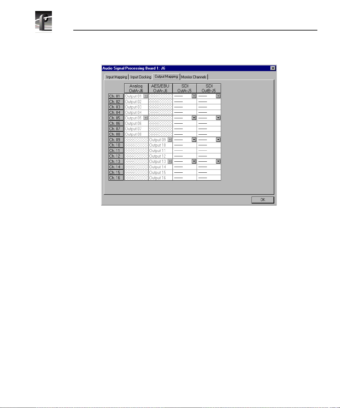
Chapter 2 Using the Profile Configuration Manager
Figure 41. Audi o Confi guration dialog box, Output Mapping tab
The columns represent the sources to the sixt een channels on the input side and
the destinations f rom the sixteen channels on the output side. The examples in
Figure 40 and Figure 41 illustrate the syste m with a PAC 208 chassis allowing
the selection of analog channels 1–8 and digital channels 9–16. A PAC 216
chassis, however, provides sixteen analog inputs and out puts or sixteen digital
inputs and outputs. For the PAC 208, rows 9 through 16 of the analog channel
column, and rows 1 through 8 of the AES/EBU channel column, are crosshatched to indi ca te that thes e chan n els are n ot sele ctab l e. In Figur e 41, in the
column labeled AES/EBU, rows 9–16 appear dimmed, indicating that this
audio type is always mapped and cannot be unmapped. Atte mpting to remap
this section resul ts in an error message.
The number of columns in the mapping grid depends on th e number of possible
input or output audio types that may be mapped to or from the disk recor der
channels. The grid is used for selecting which of the possible input or output
audio sources and destinations to map to the channels. Audio channels are
mapped in groups of four cha nnels only, and the four audio chan nels are always
mapped to consecuti ve disk channels. For example, analog channe ls 1–4 (Input
01–Input 04) in the first column of Figure 40 are mapped to the first four disk
94 Profi le Fami l y
Page 95

Input and Output Mapping
recorder channels ( Ch. 01–Ch. 04), while digital channels 9–12 (Input 09–Input
12) in Figure 41 are mapped t o another four disk recorder cha nnels (Ch. 09– Ch.
12).
In another example, channels 1–4 may be mapped to analog, channels 5–8
mapped to AES/EBU, and so forth. In addition, analog and AES/EBU audio
types have an assign ed one-to-one mappi ng to their re spective c hannels, that is,
input 1 always maps to channel 1, input 2 to channel 2, and so on.
Serial digital embedd ed audio contains sixteen audio channels grouped into
four groups of four channels. Each group can be assigned to any group of four
channels. For example, group 1 (Grp1) may be assi gned t o channels 1–4 (Ch1–
Ch4), 5–8 (Ch5–Ch8), 9 –12 (Ch9–Ch12), or 13 –16 (Ch13–Ch16). However, a
maximum of two of the four groups from a serial digital video source may be
used simultaneousl y.
Input Mapping
The Input Mapping tab is used for mapping input chan nels to Profile disk
channels. The channels must be mapped to an audio type (analog, SDI, or
AES/EBU) at all times—there is no unmapped state for input mapping.
However, channels may only be mapped to one audio type at a time. Analog and
AES/EBU channels must always be mapped directly to the same physical
channel num bers .
To map input channels:
1. Choose
Option | Aud io Co nfi guration Boa r d 1 or 2 or click an ASPB
Configuration but ton. The Audio Configuration dialog box appears (Figure
40).
2. Click the Input Mapping tab.
3. Click on a button in a column. This displays a list containing analog,
AES/EBU, or SDI audio groups. Unavailable audio groups appear dimmed.
4. Click on the group of channels you want. Any single group of AES/EBU
channels may be mapped to any group of disk channels.
5. Click
OK to accept your changes or click another tab.
Profi le Fami l y 95
Page 96

Chapter 2 Using the Profile Configuration Manager
Output Mappin g
The Output Mapping tab is used for mapping Profil e dis k channels to output
destinations. If analog or AES/EBU audio types are present, they are always
mapped to their associat ed channels. These audio types cannot be unmapped.
Channels may be mapped to multiple audio types, but of thes e only one can be
a serial digital embedded or SDI audio type.
To map output channels:
1. Choose
Configuration but ton. The Audio Configuration dialog box appears (Figure
41).
2. Click the Output Mapping tab.
3. Click on a button in a column. This displays a list containing analog,
AES/EBU, or SDI audio groups. Unavailable audio groups appear dimmed .
4. Click on the grou p of chann els y ou want. The audio c hannel may b e mappe d
to any of the outputs in groups of four.
5. Click
OK to accept your changes or click another tab.
Input Clocking
The Input Clocking tab is used for assigning video input clocking sources to
input audio channels . The first column on the left side of the dia log box displays
the disk recorder channel numbers. The last column shows the audio clock
reference source sel ection (Figure 42).
You get one system reference by default from the Reference Genlock boards,
and up to four video input reference s, depending on which video boards are
installed in your Profi le unit. Even if more than four video references are
available, only the first four input clocking references are used. If you look at
the bottom of the Configurati on Manager window, you see a graphic
representati on of the insta lled boards. A key to the board representations is
shown in Table 3.
Option | Audio Configuration Board 1 or 2 or click an ASPB
96 Profi le Fami l y
Page 97

Table 3. Board representation key
Input Clocking
Board Tag Board Type
Vid I/O SDI VA Ser ial digital com ponent video 2
Vid I CAV Component analog video 1
Vid I Cmpst Analog composite video 1
No. of Video
References
The video references shown in the Inpu t Clocking tab—Video Input 1–4 —
correspond t o the actu al video boa rds insta lled, fr om left t o right, as represente d
at the bottom of the Configuration Mana ger window.
For exampl e, a syst em that does n ot use all four ava ilabl e cl ock refer en ce s
might be configured like this. In this specific example, shown in Table 4, you
have one analog composite board and one component analog board. The panel
in the tab shows System, Video Input 1, and Video Input 2.
Table 4. Configuration example, two video input clocking sources
Board Tag Board Type
Vid I CAV Component analog video 1 Video Inp ut 1
Vid I Cmpst Analog composite video 1 Video Input 2
Board
Reference
Input Clock Reference
In the next example, a system that uses all four available clock references might
be configured with two serial digital component boards. In this specifi c
example, shown in Table 5, the panel in the ta b shows System, Video Input 1,
Video Input 2, Video Input 3, and Video Input 4.
Profi le Fami l y 97
Page 98

Chapter 2 Using the Profile Configuration Manager
Table 5. Configurati on example, four video in put clocking sources
Board Tag Board Type
Vid I/O SDI VA Ser ial digital component 1 and 2 Video Input 1,
Vid I/O SDI VA Ser ial digital component 1 and 2 Video Input 3,
Board
Reference
Input Clock Reference
Video Input 2
Video Input 4
98 Profi le Fami l y
Figure 42. Audio Configuration dialog box, Input Clocking tab
Page 99

Audio Configuration Monitor Channels Tab
To change the input clocking:
1. Choose
Configuration but ton
Option | Aud io Co nfi guration Boa r d 1 or 2 or click an ASPB
. The Audio Configuration dialog box appears. Click
the Input Clocking tab, if it isn’t already displayed.
2. Click the button in the Audio Clock Reference Source column for the desired
channels and select one of up to five choices: System (default) or Video
Input. (The number of video inputs depends on the number of available vide o
channels.) Selecting one of the video inputs sets the group of four channels
to use the selected input as thei r audio cl ocking source.
3. Click OK to accept your changes or click another tab.
Audio Configuration Monitor Chan nels Tab
Under the Monitor Channe ls tab, you can sele ct recording and playback qualit y
and adjust monitor channels.
1. Choose Option | Audio Confi gur a tio n B oa r d 1 or 2 or click an ASPB
Configuration but ton. The Audio Configuration dialog box appears (Figure
43).
Figure 43. Audio Configuration dialog box, Monitor Channels tab
Profi le Fami l y 99
Page 100

Chapter 2 Using the Profile Configuration Manager
2. Click the Monitor Channels tab.
3. Under Monitor Channels, the Channel Selection box allows you to select
which channels you want to monitor. Click next to a channel pair to select
them. You can now adjust line levels for the pair.
4. The line level range is –12 to +0 dB. If you trim the line level for an
individual channe l with the slider handle, the line level is inc remented by 1
dB; clicking on either side of the slide r handle increments the line level by
0.5 dB. The
directly into a
dB.
Level boxes show the current line level. If you enter a number
Level box, the line le vel number is r ounded to the nearest ±0.5
5. To adjust the trim for all channels at once, use the
the
Group Fader moves all channels at once, it maintains the individual
Group F ader slide r. While
channel diff ere nc es.
NOTE: If the audio interface box is not present, the Monitor group
will not appear. If you r s ystem i s con figured with an XLR 216 d igitalonly chassis, channel selection is the only option available in the
Monitor Channels group.
6. Click
OK to accept your changes or click another tab.
100 Profile Famil y
 Loading...