

Page 1
ENHANCED DISK RECORDER BOARD
Installation Manual
071-8059-00
SEPTEMB ER 2000
PROFILE FAMILY
VIDEO FILE SERVERS
Page 2

Copyright Copyright © 2000 Grass Valley Group Inc. All rights reserved. Printed in the United
States of America.
This do cument m ay not be copied i n whole o r in part , or other wise repr oduced
except as sp ec ifi ca ll y permitt ed un de r U. S. co py r i gh t law, withou t the prior wr it ten
consent of Grass Valley Group Inc., P.O. Box 59900, Nevada City, California
95959-7900
Trademarks Grass Valley, GRASS VALLEY GROUP, Profile and Profile XP are either
registe red trad em arks or trad ema rk s of Gras s Va ll ey Gr oup in the Uni ted Stat es
and/or other countries. Other trademarks used in this document are either
registered trademarks or trademarks of the manufacturers or vendors of the
associ ated pro du ct s. G rass V a lley G ro up prod uc ts ar e co ver ed by U .S. an d f or eig n
patents, issue d and pending. Additional information regardi ng
Grass Valley Grou p's tradem arks and oth er propri etary right s may be fou nd at
www.grassvalleygroup.com.
Disclaimer Product options and specifications subject to change without notice. The
informati on in this manual is furnished for informatio nal use only, is subjec t to
chang e witho ut notic e, an d shou ld not b e con strued a s a com mitme nt by G rass
Valley Group. Grass Valley Group assumes no responsibility or liability for any
errors or inaccuracies that may appear in this pub lication.
U.S. Government
Restricted Rights
Legend
Revision Status
Use, duplication, or disclosure by the United States Government is subject to
restrictions as set forth in s ubparagraph (c )(1)(ii) of t he Rights in Tech nical Data
and Comp ut er Sof twa re clau se at DFA RS 25 2.277 -7 013 or in su bpara gra ph c(1 )
and (2) of the Comm ercial Co mputer So ftware Re stricte d Rights cl ause at FAR
52.227-19, as applicable. Manufacturer is Grass Valley Group Inc., P.O. Box
59900, Nevada City, California 95959-7900 U.S.A.
Rev Date Description
December 1997 Original issue. Manual Part Number 070-9978-00
September 2000 Updated Produc t Support co ntact information.
Part Number 071-8059-00.
Page 3

Grass Valley Group Product Support
You can get technical assist ance, check on the status of problems, or report new
problems by contacting our Produc t Support Group.
Unit ed States and Canada
Monday–Friday 5:30AM–5:00PM Pa cific Time
(800) 547-8949
Europe
Monday–Friday 9:00AM–5:30PM
France
Germany 49 221 1791 234 Other +44 1753 218 777
Italy 02 25086606
01 45 29 73 00
Asia and South America
Australia
- from overseas
Beijing 86-10-62351230
Brazil 55-11-3741-8422 Taiwan 886-2-27571571
Hong Kong 852-2585-6579
02-9888 0100
61-2-9888 0100
ext. 711
World Wide
24-hour Emergency Hotline (530) 478-4148 (Cont rac t and warranty customers)
Worl d Wide Web http://www.grassvalleygroup.com/support//
FTP Site ftp.grassvalleygroup.com
E-mail profile-users@grassvalleygroup.com
United Ki ngdom 01628 405830
Japan 81-3-3448-3111
Korea 82-2-528-5299
Mexico 52-5-666-6333
Singapore 65-356-3900
Enhanced Disk Recorder Installation iii
Page 4

General Safety Summary
Review the following safet y precautions to avoid injury and
prevent damage to this product or any products connected to it.
Only qualified personne l should perform service procedures.
Injury Precautions
Do Not Operate
Without Covers
Do Not Operate in
Wet/Damp
Conditions
Do Not Opera te i n an
Explosive
Atmosphere
Avoid Exposed
Circuitry
To avoid electric shock or fire hazard , do not operate this prod uct
with covers or panels removed.
To avoid electric shock, do not operate this product in wet or damp
conditions.
To avoid injur y or fire h azar d , do no t operat e this pr oduct in an
explosive atmosphere.
To avoid injur y, remove j ewelry suc h as rings, watches, and oth er
metallic objects. Do not touch exposed connections and
components when power is present.
iv Enhanced Disk Recorder Installation
Page 5
Product Damage Precaut ions
Product Damage Precautions
Provide Proper
Ventilation
Do Not Operate With
Suspected Failures
Prevent product overhea ting by pr oviding proper ventilation.
If you suspect ther e is damage to this product, have it ins pected by
qualified servic e personnel.
Safety Terms and Symbols
Terms in This
Manual
!
!
Terms on the
Product
These terms may appear in this manual:
WARNING: Warning sta tements identify conditions or practices
that can result in persona l injur y or loss of life.
CAUTION: Caution statements identify conditions or practices
that can result in damage to the equipment or other property.
These terms may appear on the product:
DANGER indicates a personal injury ha zard immediately
accessible as one reads the marking.
WARNING indicates a personal injur y hazard not immediately
accessible as you read the marking.
Symbols on the
Product
!
CAUTION indicates a hazard to property, including the product.
The following symbols may appear on the produc t:
DANGER high voltage
Protective ground (ear th) terminal
ATTENTION – refer to manual
Enhanced Disk Recorder Installation v
Page 6
Service Safety Summary
WARNING: These instru ct ion s ar e for us e by qu alifi ed
!
service personnel only . To avoi d personal injury, do not
perform any se rvicin g unl ess you ar e qualif ied to do s o. Refer
to all safety summaries before performing service.
Do Not Service
Alone
Disconnect Power To avoid electric shock, disconnect the main power by means of
Use Care When
Servicing With
Power On
Do not perform internal servi ce or adjustment of this product
unless another person capable of rendering first aid and
resuscitation is present.
the power cord or, if provided, the power switch.
Dangerous voltages or currents may exist in this product.
Disconnect power and remove batte ry (if applicable) before
removing protectiv e panels, soldering, or replacing componen ts.
To avoid electric shock, do not touch exposed connections.
vi Enhanced Disk Recorder Installation
Page 7

Certifications and Compliances
Certifications and Compliances
FCC Emission
Control
Canadian EMC
Notice of
Compliance
This equipment has been tested and found to comply with the
limits for a Class A digital de vice, pursuant to Part 15 of the FCC
Rules. These limits are designe d to provide reasona ble protection
against harmful inter ference when the equipment is operated in a
commercial environm ent. This equipment g enerates, uses, a nd can
radiate radio frequency energy and, if not installed and used in
accordance with the instruction manual, may cause harmful
interference to radio communications. Operation of this
equipment in a residentia l are a is likely to cause harmful
interferen ce in wh i ch cas e the us er w ill be requ ired to correct the
interference at his own expense. Changes or modifications not
expressly approved by Grass Valley Group can affect emission
compliance and could void the user’s authority to operate this
equipment.
This digital apparatus doe s not exceed the Class A limits for
radio noise emissi ons from digital appa ratus set out in t he Radio
Interference Regula tions of the Canadian Department of
Communications.
Le présent appareil num érique n’émet pas de bruit s
radioélectriques dépassant les limite s applicables aux appareils
numériques de la classe A préscrites dans le Règlement sur le
brouillage radioélectrique édicté par le ministère des
Communications du Canada.
EN55022 Class A
Warning
For products that comply with Class A. In a domesti c environment
this product may cause radio inte rference in which case the user
may be required to take adequate measures.
Enhanced Disk Recorder Installation vii
Page 8

Certification
Category Standard
Safety Designed/tested for compliance with:
UL1950–Safety of Informat ion Technology Equipment, including Electri cal
Business Equipment (Third Edition, 1995)
IEC 950 – Safety of Information Technology Equipment, including Electrical
Business Equipment (Second edition, 1991)
CAN/CSA C22.2, No. 950-95–Safety of Information Technology Equi pm ent,
includ ing Electrical Business Equipment
EN60950–Safety of Information Technology Equipme nt, including El ectrical
Business Equipment
viii Enhanced Disk Recorder Installation
Page 9

Enhanced Disk Recorder Installation
Introduction
Use these instructions to install a second disk recorder in a Profile system. The Slave
Enhanced Disk Recorder (EDR) board provides two JPEG codecs and two SCSI-2
channels. Note that these two codecs may require adding another video I/O board or
additional disks .
You can install the board with the Profi le chassis fully extended on the rack slides if
the equipment rack is a dequately mounted to prevent tipping, and if there is sufficient
slack in the cables connected to the rear panel to allow the chassis to fully extend on
the slides.
If it is necessary for you to remove the Profile chassis from the equipment rack to
perform this insta lla tio n , refe r to the Pr ofile system’s Installation manual for
instructions.
WARNING: Unless the equi pment rack is adequa t ely a nch o red , the r ac k cou ld tip
when the Profile chassis is extended on the rack slides. To avoid possible injury,
!
make sure the rack is f irmly secured before extendi ng the chassis on the rack slides .
System Requirements
The Profile System Software insta lled in the Profile system must be Version 2.2 or
higher. To check the software version installed in your Profile system, open the
VrdPanel application a nd choose
listed in the Product Version field in the displayed window.
Kit Contents
In addition to this manual, the kit includes the following items:
• Label strip (1)
• PCI Interconnect board (1)
• SCSI B cable (1)
• SCSI D cable (1)
• Slave Enhan ce d Di sk Re co rder board (1)
Help | About VdrPanel. The software version is
Enhanced Disk Recorder Installation 1
Page 10

Enhanced Disk Recorder Installation
Tools Required
Tools required, but not supplied, to install this kit are:
• Torx tool with T10 and T15 tips
• 3/16-inch hex wrench
• Electrostati c discharge (ESD) grounding straps
Electrostatic Precautions
CAUTION: This product contains components that are highly sensitive to
electrostatic discharge. To protect these components from damage and to maintain
!
product reliability, take the f ollowing precautions when handling the circ uit boards:
• Handle all circuit boards in a static-protected area capable of controlling static
charge on conductive materials, people, and non-conductive materials.
Static-prote cted areas include non-static table tops and non-st atic floor mats.
• Handle the cir cuit boards only by the edges. A void t ouching the prin ted w ires on
the back of the circuit board as much as possible.
• Leave the board in its static -shiel ded bag until you are ready t o install the boar d.
• Wear ESD grounding straps when handling boards not protected by
static-shielded bags.
2 Enhanced Disk Recorder Installation
Page 11

Installation Procedures
Installation Procedures
The manual includes step-by-step instructions for:
• Removing the Profile unit fro m the instrument rack (this page)
• Removing the chassis covers (page 4)
• Removing the circuit board hold- down brackets (page 5)
• Repositioning cir cuit boards (page 6)
• Selecting a board location ( page 7)
• Installing the Slav e E DR b o ard (p ag e 21)
• Connecting the SCSI cables (page 23)
• Installing the PCI Inte rconnect board (page 27)
• Reassembling the system (page 28)
• Verifying the installation (page 29)
There is also a section that discusses internal audio clock cabling (page 16) .
Removing the Profile Unit from the Instrument Rack
If you cannot or do not want to install the Slave EDR board with the Prof ile chassis
extended on the rack slides (as explained in the Profile system’s Installation manual),
you will need to use the following procedure to remove the Profile unit from the
instrument rack:
1. Remove all cabling connected to the Profile chassis.
2. Loosen the front-panel retaining scre ws.
3. Grasp the handles and pull the chassis out until the slide sections latch. This holds
the Profile chassis fi rmly in that position.
WARNING: Removing the Pro file chass is from t he rack requi res two peopl e; it i s too
!
heavy for one person to lift.
4. Press both track stop latch buttons (visible in the stop latch holes) and carefully
slide the Profile chassis free of the tracks.
Enhanced Disk Recorder Installation 3
Page 12
Enhanced Disk Recorder Installation
Removing the Chassis Covers
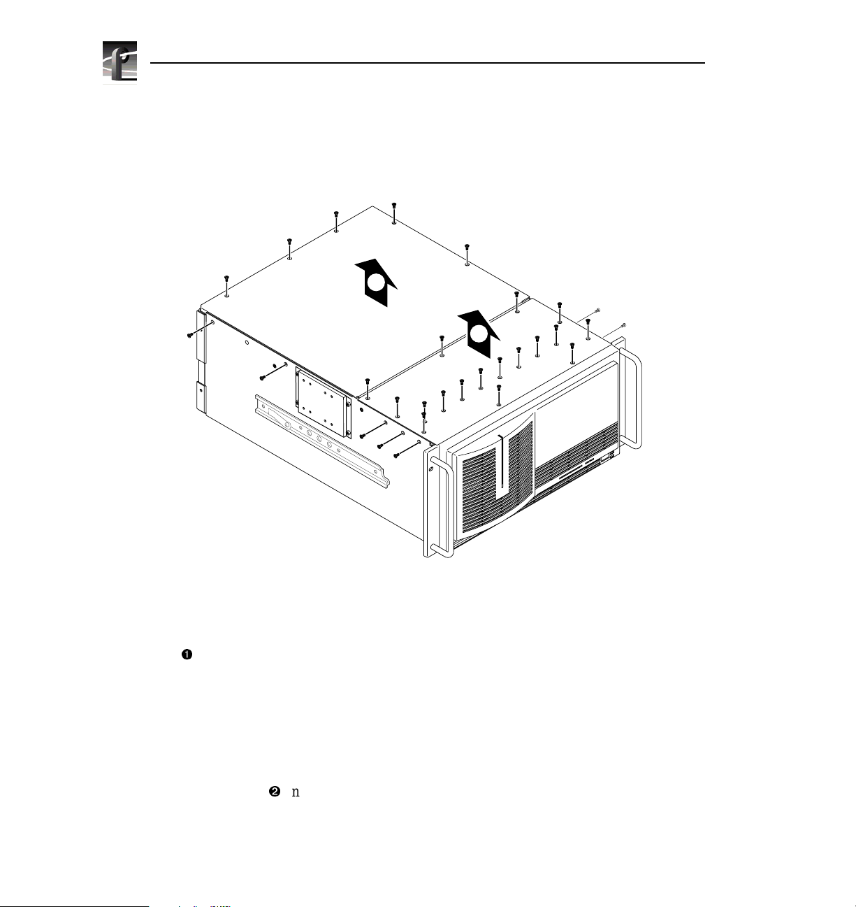
Use the following procedure to remove the chassis covers:
1. Turn off Profile system power and remove the power cord.
2
9675-9
1
Figure 1. Removing the Chassis Cover Screws
2. Using a Torx tool with a T10 tip, remove the top screws from the front chassis
cover and then use t he T15 tip to remove the side scre ws. Remove the front cover
(Ê in Figure 1). The front chassis c over must be removed fir st because it over laps
the rear chassi s cover.
NOTE: Take care not to lose the chassis screws—they are required to meet EMI
specificati ons for the Profile system. Also note that the PDR100 may not have the
same number of screws as shown in Figure 1.
3. Using a Torx tool with a T10 tip, remove the rear chassis screws and then r e move
the rear cover (
4 Enhanced Disk Recorder Installation
Ë
in Figure 1).
Page 13

Removing the Circuit Board Hold-down Brackets
Removing the Circuit Board Hold-down Brackets
There are two hold-down brackets (sh own in Figure 2) you must r emove to access the
circuit boards. Use the procedure below to remove these brackets.
3
4
1
2
9675-2
Figure 2. Removing the Circuit Board Hold-down Brac kets
1. Using a Torx tool with a T10 tip, remove the screw (Ê in Figure 2) which secures
the rear board hold-down bracke t.
2. Lift the hold-down bracket (Ë in Figure 2) out of the chassis and set aside.
3. Using a Torx tool with a T10 tip, remove the screw (Ì in Figure 2) which secures
the front board hold-down bracke t.
4. Lift the hold-down bracket (Í in Figure 2) out of the chassis and set aside.
Enhanced Disk Recorder Installation 5
Page 14

Enhanced Disk Recorder Installation
Repositioning Circuit Boards
Installing the Slave EDR board may require repositioning one or more currently
installed boards to either make room for the new board or meet internal cabling
constraints. When unplugging boards it may also be necessary to r emove a screw that
mounts an adjacen t circui t board or , in the cas e of some shor ter circuit boards, i t might
be necessary to remove an adjacent tall circuit board to ease removal of the shorter
board.
Use the following procedure to unplug a circuit board from the motherboard:
1. Remove all interior and rear panel cables, if any, from the circuit board.
2. Using a Torx tool with a T15 tip, remove the two bracket mounting screws: one
that anchors t he top of the bracket f rom inside the chassis (Ê in Figure 3) and one
that anchors the bottom of the bracket from the outside rear panel of the chassis
(Ë in Figure 3).
CAUTION: To avoid damage to a c ircuit boa rd during remova l or instal lation: 1 ) Do
not rock the circuit board in the EISA Bus connector — pull it straigh t up. 2) Do not
!
grasp or push on the rear-panel connector s when removing or installing circuit
boards in the card slots.
Figure 3. Removing the Board Mounting Bracket Screws
6 Enhanced Disk Recorder Installation
1
2
9040-13
Page 15

3. Extract the circuit board:
- For tall circuit boards, use the extracti on lever on the front of the board and
the extraction ri ng at the back of the board to lif t the circuit board f ree of the
connectors on the motherboard.
- For short circuit boards, carefully grasp the board and lift upward to free
the circuit board from the motherboa rd connectors. You might need to
remove an adjacent tall board to get enough room for a safe hold on the
shorter board.
Board Location Guide
This section provides a simple approach you can use to determine proper board
location. It explains the relationship between the motherboard and video router
connectors and provides ta bles, charts and examples to assist you in install ing boards.
Table 1 (page 8) identifies the inputs and outputs of all Profile boards currently
available, as well as the input and output connec tions on the vi deo router conne ctors on
the motherboard. Use this information when:
• Adding a new circuit board to your Profile system and you need to select an
installation slot.
• Moving boards to meet requirement s for a new board.
Board Location Guide
Keep in mind th at some ci rcuit boar ds must occu py a specific slot, whi le you can install
other boards in almost any slot that meets their I/O requirements.
NOTE: If more than one slot appears in a column in Table 1, the slots are listed in
order of prefer en ce.
Video Router to Motherboard Relationship
The video router provides and contr ols video data to twelve connectors on the
motherboard. These video data connectors are aligned with the main motherboard
connectors for slots J5 through J16. Since the Ref erence Genlock (Ref Gen) board must
occupy J16 to provide the necessary system clocks, this discussion excludes J16.
When choosing a board slot, the major constr aint on a slot is how the board connects
to the video router. Not all boards require the same number of video I/O connections
and not all video data connectors pr ovide the same number of video I/O connections.
Therefore, you must know how many input and output connect ions the board you want
to install needs, as well as the avai lable slots that meet those requirements.
Enhanced Disk Recorder Installation 7
Page 16

Enhanced Disk Recorder Installation
Table 1. Board Location Guide
Board Video Router
Connection
Requirements
Inputs Outputs PDR 100 PDR 200
Recommended Slot Other
Possible
Slots
Restrictions
CPU None n/a J1 J1 None
VGA n/a n/a J2 J2 None
LAN n/a n/a J3 J3 None
SCSI n/a n/a J4 J4 None
RefGen n/a n/a J16 J16 None
RS422 n/a n/a J17 J17 None
FibreChannel n/a n/a J15 J8 J5–J15 Must be adja cent to Master EDR
Master ED R 2 2 J14 J9 J5–J15 Must be adja cent to Slave EDR an d (if
installed) Fibr e Channel
Slave EDR 2 2 J13 J10 J5–J15 Must be adjacent to Ma ster EDR
Master DR 2 2 J14 n/a J5–J15 Must be in adjacent to Slave DR
Slave DR 2 2 J15 n/a J5–J15 Must be adjacent to Master DR
Serial Digital
I/O
22 J11J14, J15J5–J15 Can’t go in J5 if Mi x Effects is in J6 or
in J8 if Mix Effects is in J7
Decoder None None J8 J5 J7, J11 Must be adjacent to Analog
Composite In
Analog
None 1 J9 J6 J8, J12 Must be adjacent to Decoder
Composite In
Analog
Composite I/O
22 J11J14, J15J5–J15 Can’t go in J5 if Mi x Effects is in J6 or
in J8 if Mix Effects is in J7
Mix Effect s 6 2 J7 J7 J6 Only J6 and J7 have 5 inputs; board
must be able to get a share d inpu t (the
6th) from an adjacent slot (J5 or J8)
4 Ch. Analog
Out
4 None J6 J6 J 12, J7,
J11
Only J6, J7, J11, and J12 have 3 (or
more) inputs. If in J11 or J12, board
must be able get a shared input (the
4th) from an adjacent slot (J10 or J13)
Analog
Composite
Monitor
Audio Signal
4 None J12 J12 J6, J7, J11 Only J6, J7, J11, and J12 h ave 3 (or
more) inputs. If in J11 or J12, board
must be able get a shared input (the
4th) from an adjacent slot (J10 or J13)
None None J13 J13 J5–J15
Processing Bd
(ASPB)
CAV In None 1 J5 J5 J5–J15
Audio I/O None None J5–J15 n/a J5–J15
8 Enhanced Disk Recorder Installation
Page 17

Board Location Guide
Video Router I/O Connections
Now let’s look at the video router connections available in slots J5–J15. Table 2
(page 10) lists the video route r input and output connections. Here’s a description of
what appears in each column:
• The Slot column lists each slot on the motherboard connected to the video router.
• The Board column lists the boards currently installed, as well as the boards you
want to install.
• The Input column identifies data input connections to the slots (boa rds) from the
video router. The numbers in the blocks correspond to the order in which input
connections are assigne d at the video router connector.
• The Output column identifies data output connections from the slots (boards) to
the video router. The numbers in the bloc ks correspond to the order in which output
connections are assigne d at the video router connector.
The shaded blocks in the diagram indic ate video router connections shared between
slots. Shared c onnec tion are availa ble t o eithe r sl ot, but not b oth s lots at the same time.
Specifically , in Tabl e 2:
• The shaded blocks betwe en slots J5 and J6, slots J7 and J8, slots J10 and J11, and
slots J12 and J13 indicate shar ed input connections.
• The shaded blocks betwe en slots J8 and J9, sl ots J10 and J11, a nd slots J12 and J13
indicate shared output connections.
The next section describes how to select a board location.
Enhanced Disk Recorder Installation 9
Page 18

Enhanced Disk Recorder Installation
Table 2. Board Location Chart
Slot Board Input Output
J5
J6
J7
J8
J9
J10
J11
J12
J13
J14
J15
1
1
23
11
2
3
42
5
6
1 43
22
11
2 34
11
22
3
4 34
11
23
11
23
2
6
5
4
31
2
1
21
1
4 43
3
2
11
2 43
1
2
2
34
1
2
2
2
1
2
2
10 Enhanced Disk Recorder Installation
Page 19

Board Location Guide
Selecting a Location
The following procedur e explains how to select a location for a board you want to add
to your Profile system. Use Table 2 (page 10) as a template for recording information
for the new board placement.
1. On Table 2, put a 3 in each input and output block used by every board currently
installed in your Profile system, starting with the 1 block for each board. Look in
Table 1 (page 8) to get this information.
2. Using Table 1, find the input and output requi rements, and the recommended slot
and alternate slots (if any), for the board you want to install.
3. On Table 2, complete the following steps:
-In the Board column, next to the appropriate sl ot number, write the name of
the board you want to install.
-Put an 8 in the appropriate input blocks.
-Put an 8 in the appropriate output blocks.
NOTE: If you ca n’t find an open slot with an I/O which meets the requirements of
the board you want to install, you will have to move existing boards. You can use
Table 1 and Table 2 to experiment with various board locations before deciding
which board co nfig u rat i on yo u wa nt to us e.
The following examples show how to use the above procedur e to select a location for
the Slave EDR b oard.
Enhanced Disk Recorder Installation 11
Page 20

Enhanced Disk Recorder Installation
Example 1
In this example you’re going to add the Slave EDR board to a Profile 202D system
which has the following boards already installed: Master EDR, Serial Digital I/O and
Audio Signal Processing.
Table 3 (page 13) shows how the Board Location Chart should look a ft er you have
completed the following procedure.
1. On Table 2 (page 10), put a 3 in each input and output block used by every boa rd
currently install ed in your Profil e sys tem, starti ng with the 1 block for each board.
Look in Table 1 (page 8) to get this information.
a. For the Master EDR board in slot J9, which requires two inputs and two
outputs:
-Put a 3 in Input blocks 1 and 2 for slot J9.
-Put a 3 in Output blocks 1 and 2 for slot J9.
b. For the Audio Signal Processing board (ASPB) in slot J13:
- There are no video router I/O connection r equirements—no action is
required.
c. For the Serial Digital I/O boar d in slot J14 , which requi res two inputs and two
outputs:
-Put a 3 in Input blocks 1 and 2 for slot J14.
-Put a 3 in Output blocks 1 and 2 for slot J14.
2. Using Table 1, find the input and output requi rements, and the recommended slot
and alternate slots (if any), for the Slave EDR board. That table shows the Slave
EDR board needing two input bloc ks and two output blocks. It a lso shows t hat the
recommended slot posi tion is J10 and th at the boa rd must be adjacent to the Master
EDR board. Since the Master EDR board occupies slot J9 and the recommended
slot for the Slave EDR board (J10) is open, that is the slot you must use.
3. On Table 2, complete the following steps:
- Write Slave EDR in the Boards column for slot J10.
-Put an 8 in Input blocks 1 and 2 for slot J10.
-Put an 8 in Output blocks 1 and 2 for slot J10.
12 Enhanced Disk Recorder Installation
Page 21

Table 3 . C o mpleted Ch a r t fo r E x ample 1
Slot Board Input Output
1
J5
J6
J7
J8
J9 Master EDR
J10 Slave EDR
J11
J12
1
23
11
2
3
42
5
6
1
2
1
2
11
22
3
4 34
2
6
5
4
31
2
1
21
2
34
1
3
43
33
3
8
1
8
2
8
8
34
4 43
3
2
11
2 43
J13 ASPB
1
1
3
1
3
2
J14 S erial Digital I/O
J15
2
3
11
23
3
3
2
Board Location Guide
2
2
1
2
2
1
Enhanced Disk Recorder Installation 13
Page 22

Enhanced Disk Recorder Installation
Example 2
This examp le is si mila r to Exa mple 1 ( page 12 ), wi th the ex cept ion t hat a Fi bre Ch annel
board has been previously installed in the Profile 202D system.
Table 4 (page 15) shows how the Board Location Chart should look a ft er you have
completed the following procedure.
1. On Table 2 (page 10), put a 3 in each input and output block used by every boa rd
currently install ed in your Profil e sys tem, starti ng with the 1 block for each board.
Look in Table 1 (page 8) to get this information.
a. For the Fibre Channel board in slot J8:
- There are no video router I/O connection r equirements—no action is
required.
b. For the Master EDR board in slot J9, which requires two inputs and two
outputs:
-Put a 3 in Input blocks 1 and 2 for slot J9.
-Put a 3 in Output blocks 1 and 2 for slot J9.
c. For the Audio Signal Processing board (ASPB) in slot J13:
- There are no video router I/O connection r equirements—no action is
required.
d. For the Serial Digital I/O board in slot J14 , which requi res two inputs and two
outputs:
-Put a 3 in Input blocks 1 and 2 for slot J14.
-Put a 3 in Output blocks 1 and 2 for slot J14.
2. Using Table 1, find the input and output requi rements, and the recommended slot
and alternate slots (if any), for the Slave EDR board. That table shows the Slave
EDR board needing two input bloc ks and two output blocks. It a lso shows t hat the
recommended slot posi tion is J10 and th at the boa rd must be adjacent to the Master
EDR board. Since the Master EDR board occupies slot J9 and the recommended
slot for the Slave EDR board (J10) is open, that is the slot you must use.
3. On Table 2, complete the following steps:
- Write Slave EDR in the Boards column for slot J10.
-Put an 8 in Input blocks 1 and 2 for slot J10.
-Put an 8 in Output blocks 1 and 2 for slot J10
14 Enhanced Disk Recorder Installation
Page 23

Table 4 . C o mpleted Ch a r t fo r E x ample 2
Slot Board Input Output
1
J5
J6
J7
J8 FibreChannel
J9 Master EDR
J10 Slave EDR
J11
J12
1
23
11
2
3
42
5
6
1
2
1
2
11
22
3
4 34
2
6
5
4
31
2
1
21
2
34
1
3
43
33
3
8
1
8
2
8
8
34
4 43
3
2
11
2 43
J13 ASPB
1
1
3
1
3
2
J14 S erial Digital I/O
J15
2
3
11
23
3
3
2
Board Location Guide
2
2
1
2
2
1
Enhanced Disk Recorder Installation 15
Page 24

Enhanced Disk Recorder Installation
Audio Clock Cabl ing
NOTE: Although the Slave EDR board does not require audio clock cabl ing, the
information is included here i n case you ha ve to move other boards to make room for
the Slave EDR board.
This section provides information about audio clock cabling. In general, if all the
audio/video devices are connected to house reference, audio clock cabling is not
required. The need for audio clock cabling arises when an external audio clock signal
from the appropriate video board must be used to synchronize the audio to the video.
Cabling between connecto rs on the top of the video boards and connectors on the top
of the ASPB provide the external audio cl ock signals.
ASPB Audio Clock Cabling
The ASPB provides input of four external au dio clock signals, one to each
Audio 1–Audio 4 bank, where each bank consists of four audio channels. ASPB
Audio 1–Audio 4 connectors begin closest to the rear panel and go toward the front
panel.
In general, the video board in the lowest numbered slot must provide the audio clock
signal to the Audio 1 bank, the video board in the next lowest numbered slot must
provide the audio clock sig nal to the Audio 2 bank, etc. For example, if you have video
boards in slots J5 and J11, the audio clock signal from the video board in J5 must be
connected to Audio 1 on the ASPB and the audio clock signal from the video bo ard in
J11 must be connected to Audio 2 on the ASPB. If, however, t he video board in J5 has
two audio clock signals, those signals must be connected to Audio 1 and Audio 2,
respectively, on t he ASPB and the a udio c lock si gnal f rom t he video bo ard i n J11 must
be connected to Audio 3.
Figure 4 (page 17) and Figure 5 (page 18) show examples of external a udio clock
cabling with the ASPB. In Figur e 4, the Analog Composite I/O boards, insta lled in slots
J14 and J15, are the only video boards. The audio cl ock cable connections are:
• Channel A of the board in slot J14 to Audio 1 on the ASPB in slot J13.
• Channel B of the board in slot J14 to Audio 2 on the ASPB in slot J13.
• Channel A of the board in slot J15 to Audio 3 on the ASPB in slot J13.
• Channel B of the board in slot J15 to Audio 4 on the ASPB in slot J13.
16 Enhanced Disk Recorder Installation
Page 25

Audio Clock Cabling
J17 J13J16
Ch. B
Ch. A
Figure 4. Example of Audio Clock Cabling in a PDR204A
J15 J14 J6J7
Composite I/O
J12
Audio 4
Audio 3
Audio 2
Audio 1
ASPBAnalog
J11 J9
J10
J8
J5
J4 J3
0044-2
In Figure 5 (page 18), the Analog Composite I/O board installed in slot J11 makes it
the first video board (coun ting from J5 to J15) and the Serial Digital I/O board in slot
J14 becomes the second video board. The new Audio clock cable connections should
now be:
• Channel A of the board in slot J11 to Audio 1 on the ASPB in slot J13.
• Channel B of the board in slot J11 to Audio 2 on the ASPB in slot J13.
• Channel 1 of the board in slot J14 to Audio 3 on the ASPB in slot J13.
• Channel 2 of the board in slot J14 to Audio 4 on the ASPB in slot J13.
Keep in mind that the ASPB only provides for input of four audio clock signals. Also
note the following:
• Figure 5 is an example of a two-channel PDR200 with one Serial Digita l
I/O board.
• If you have a four-channel PDR200 with two Serial Digital I/O boards, all four
ASPB audio clock inputs may be connected.
Enhanced Disk Recorder Installation 17
Page 26

Enhanced Disk Recorder Installation
• If all four ASPB clock inputs are connected and you then install another video
board, you will have more audio clock signals than you have connections on the
ASPB (two from the Analog Composite I/O board and four from the two Seria l
Digital I/O boards).
You will have to determine how you want to set up your system; that is, what you want
to use as the signal sources that synchronize the audio to the video. While this is
primarily a software configuration function, keep in mind that how you configure the
audio clocks in software must match the physical connections.
NOTE: The Configuration Manager (see the Profile Family User Manual) allows
you to assign either the syste m clock or a video sourc e as the source of audio c locks.
If you select a video source, then you must ensure that the audio associ ated with that
video sourc e is connected to the corre ct audio cha n nel co nn ect o rs .
Audio 4
Audio 3
Audio 2
Audio 1
Ch. 2
Ch. 1
J17 J13J16
Figure 5. Example of Audio Clock Cabling in a PDR202D
J15 J14 J6J7
ASPBSerial
Digital I/O
J11 J9
J12
J10
Ch. B
Ch. A
Analog
Composite I/O
J8
J5
J4 J3
0044-3
18 Enhanced Disk Recorder Installation
Page 27

Audio Clock Cabling
Audio I/O Audio Clock Cabling
Figure 6 (page 20) shows an exam ple of an Analog Compos ite I/O board insta llation in
a PDR100 with two Analog Audio I/O boards. In the figure, audio clock cable
connections are from:
• Analog Composite I/O Channel A t o the RECORD connector o n the Anal og Audio
I/O board in the lowest num bered slot from slot J5 t o slot J1 5 (in this e xample, J9).
• Analog Composite I/ O Channel B to the RECORD connector on the Analog Aud io
I/O board in the next lowest slot (in this e xample, J10).
• PLAY cables on both Audio I/ O boards to any of t he system cl ocks on th e RefGen
board, or to any board which has system clock connectors (such as the Analog
Composite Output board).
Figure 6 is an example. If you have other video boards installed, or add Audio I/O
boards, you will need to determine which video source you want to use for the audio
clock signals and then make the appropriate Audio I/O board connection adjustments.
Enhanced Disk Recorder Installation 19
Page 28

Enhanced Disk Recorder Installation
J17 J13J16
Ref Gen Analog
J15 J14 J6J7
Play Cables
Record Cables
J11 J9
J12
Audio
2 or 4
J10
Audio
1 or 3
J8
Ch. A
Composite I/O
Ch. B
J5
J4 J3
0044-4
Figure 6. Example of Audio Clock Cabling with Two Audio I/O Boards
20 Enhanced Disk Recorder Installation
Page 29

Installing the Slave Enhanced Disk Recorder Board
Installing the Slave Enhanced Disk Recorder Board
The following procedure exp lains how to install the Slave EDR board:
1. Disconnect the SCSI cable from the Master EDR board (Ê in Figure 7). Note that
there are two SCSI cables to disconnect if your system has eight hard drives.
2. Determine which slot the Slave EDR board will be using. Refer to Table 1
(page 8). If you aren’t sure how to interpret Table 1, read the section titl ed “Board
Location Guide” (page 7).
3. If necessary, remove the slot cover where you want to install the board.
4. Align the board with the connectors on the mothe rboard, making sure the extractor
on the front end of the board is in the up position. Firmly press down on the board
(Ë in Figure 7) until the board seats. The board is proper ly seated when the top of
the rear mounting bracket is resting on the rear chassis wall shelf.
Slave EDR Board
Master EDR Board
2
1
1
9978-1
Figure 7. Installing the Slave EDR Board
Enhanced Disk Recorder Installation 21
Page 30

Enhanced Disk Recorder Installation
5. Using a Torx tool with a T15 tip, ins tall t he two mountin g bra cket scre ws: one that
anchors the to p of the bracket from inside the chassis (Ê in Figure 8) and one that
anchors the bottom of the bracket from the outside rear panel of the chassis
(Ë in Figure 8).
1
2
Figure 8. Installi ng the Board Mounting Bracket Screws
6. If necessary, install the blank circui t board brackets in the empty boa rd slots on the
rear panel of the chassis.
7. Reconnect any audio clock cables previously remo ved. Refer to “Audio Clock
Cabling” (page 16) if you need help determining cable connections.
8. Using a Torx tool with a T10 tip, reinstall the rear board hold-down bracket. See
Figure 2 (page 5).
CAUTION: To prevent damage to a Monitor board, if installed, do not install a short
!
board extension on the front hold-down bracket at the Monitor board location.
9. If necessary, reconfigure the front board hold-down, moving or removing a short
board extension.
10. Using a Torx tool with a T10 tip, reinstall the front boa rd hold-down bracket. See
Figure 2.
22 Enhanced Disk Recorder Installation
9040-13
Page 31

Connecting the SCSI Cables
After installi ng the Slave EDR board, you need to reconnect the SCSI cables you had
removed earlier. You will also need to add other SCSI cables, depending on your
system configurati on. All necessary cables are included in this kit.
Table 5 lists SCSI cable connecti ons for a Profile system that has eight hard drives, a
Master EDR and a Slav e E DR.
Table 5. SCSI Cables Connections
Connecting the SCSI Cables
Connect This
SCSI Cable:
A Hard Drive (Bank A) Master EDR
B Master EDR External B slot
C Hard Drive (B ank C) Slave EDR
D Slave EDR External D slot
From: To:
After determining which S CSI cable s your s ystem needs, use the proc edure, e xplaine d
below, to conn ect the cab l es.
NOTE: For illustrative purposes, the following procedure shows a Profile system
that includes eight hard drive s, a Mast er EDR board and a Slave EDR board. Your
system may have a different configuration.
Enhanced Disk Recorder Installation 23
Page 32

Enhanced Disk Recorder Installation
1. Connect the SCSI A cable from the Hard Drive (Bank A) to the SCSI A conne ctor
on the Master EDR board, and the SCSI C cable from the Hard Drive (Bank C) to
the SCSI C connector on the Slave EDR board, as shown in Figure 9.
Master EDR Board
Slave EDR Board
Figure 9. Connecting the SCSI A and SCSI C Cables
24 Enhanced Disk Recorder Installation
SCSI A Connector
SCSI C Connector
9978-5
Page 33

Connecting the SCSI Cables
2. Using a 3/16-inch hex wrenc h, r emove and s et a side t he meta l plate tha t covers the
SCSI D slot and (optionally) the SCSI B slot on the back panel of the Profile
chassis. See Figure 10.
NOTE: Skip this step if you installing the Slave EDR board into a Profile PDR100.
SCSI D Slot
SCSI B Slot
Figure 10. Removing the Back Panel Metal Plates
Enhanced Disk Recorder Installation 25
9978-2
Page 34

Enhanced Disk Recorder Installation
3. Connect the SCSI B cable from the Master EDR board to the SCSI B slot on the
back panel of the Profile chassis, and the SCSI D cable f rom the Slave EDR board
to the SCSI D slot on the back panel, as illustrated in Figure 11.
SCSI D Cable
SCSI B Cable
Master EDR Board
Slave EDR Board
Figure 11. Connecting the SCSI B and SCSI D Cables
26 Enhanced Disk Recorder Installation
9978-3
Page 35

Installing the PCI Interconnect Board
The PCI Interconnec t board is a high-spe ed bus used to m ove data betwe en the Mas ter
EDR and the Slav e ED R.
To connect the PCI Interconnect board, as illustrated in Figure 12:
1. Align the keys on the PCI Interconnect board with the key on the Master EDR
board and with the key on the Slave EDR board.
2. Press down firmly on the Slave EDR board to ensure the board is properly seate d.
PCI Interconnect
Master EDR Board
Slave EDR Board
Installing the PCI Interconnect Board
Board
Alignment Keys
Figure 12. Install ing the PCI Interconnect Board
9978-4
Enhanced Disk Recorder Installation 27
Page 36

Enhanced Disk Recorder Installation
Reassembly Procedure
After installing the Slave EDR board and adding any other I/O boards you want, use
the following procedur e to reassemble your system:
1. Using a Torx tool with a T10 tip, reinstall the rear chassis cover with the screws
previously removed. See Figure 1 (page 4).
2. Using a Torx tool with T10 and T15 tips, reinstall the front chassis cover with th e
screws previously removed. See Figure 1.
3. Apply the stick-on label to the appropriate location on the Profile chassis rear
panel to identify the location of the Slave EDR board and any other boards you
may have added or repositioned.
4. If you previously removed the Profile chass is from the mounting rack, reinstall
the chassis , as exp lained in the Profile s ystem’s Installation manual.
5. Reconnect all cables previously removed.
6. Apply power to the Profile system.
7. Verify the installation. See “Installation Verification” (page 29) for mo re
information.
8. Configure the system for the Slave EDR board. Refer to the chapter in the
Profile Family User Manual that describes the Profile Configuration Manager.
28 Enhanced Disk Recorder Installation
Page 37

Installation Verification
Installation verification of a board you have added to your Profile system consists of
using the Diagnost ics window to ensure that the sy stem recognizes the board. Use th e
following proce dure to check for recognition of the Slave EDR board you just ins talled:
1. From the Windows NT 4.0 desktop, open the Diagnostics window by choosing
Start | Programs | PDR Debug Tools | PDR Diagnostics.
2. Ensure that the Slave EDR board appears in the slot where you install ed it.
Figure 13 is an example of what would appear in th e Diagnostic window if all the
boards shown in Example 2 (page 14) were actually installed.
Slot J1
Slot J2
Slot J3
Slot J4
Slot J5
Slot J6
Slot J7
Slot J8
Slot J9
Slot J10
Slot J11
Slot J12
Slot J13
Slot J14
Slot J15
Slot J16
Slot J17
Mother Bd
Installation Verification
FibreChannel
Master EDR
Slave EDR
ASPB
Serial Digital I/O
Mother Board
Quit
Figure 13. Example Diagnostics Window Display
This completes the instal lation of the Profile Enhanced Disk Recorder board.
Enhanced Disk Recorder Installation 29
Page 38

Enhanced Disk Recorder Installation
30 Enhanced Disk Recorder Installation
 Loading...