

Page 1
ANALOG COMPOSITE I/O
Installation Manual
071-0044-01
NOVEMBER 2000
PROFILE FAMILY
VIDEO FILE SERVERS
Page 2

Copyright Copyright © 2000 Grass Valley Group Inc. All rights reserved. Printed in the United
States of America.
This do cument m ay not be copied i n whole o r in part , or other wise repr oduced
except as sp ec ifi ca ll y permit ted under U. S. copyri gh t law , wi th out the prior writ ten
consent of Grass Valley Group Inc., P.O. Box 59900, Nevada City, California
95959-7900
Trademarks Grass Valley, GRASS VALLEY GROUP, Profile and Profile XP are either
registe red trad em arks or trad ema rk s of Gras s Va ll ey Gr oup in the Uni ted Stat es
and/or other countries. Other trademarks used in this document are either
registered trademarks or trademarks of the manufacturers or vendors of the
associ ated pro du ct s. G rass V a lley G ro up prod uc ts ar e co ver ed by U .S. an d f or eig n
patents, issued and pending. Additional info rmation regarding
Grass Valley Grou p's tradem arks and oth er propri etary right s may be fou nd at
www.grassvalleygroup.com.
Disclaimer Product options and specifications subject to change without notice. The
informati on in this manual is furnished fo r informat ional use only, is sub ject to
chang e witho ut notic e, an d shou ld not b e con strued a s a com mitme nt by G rass
Valley Group. Grass Valley Group assumes no responsibility or liability for any
errors or inaccuracies that may appear in this publicatio n.
U.S. Government
Restricted Rights
Legend
Revision Status
Use, duplication, or disclosure by the United States Government is subject to
restrictions as set forth in s ubparagraph (c )(1)(ii) of t he Rights in Tech nical Data
and Comp ut er Sof twa re clau se at DFA RS 25 2.277 -7 013 or in su bpara gra ph c(1 )
and (2) of the Comm ercial Co mputer So ftware Re stricte d Rights cl ause at FAR
52.227-19, as applicable. Manufacturer is Grass Valley Group Inc., P.O. Box
59900, Nevada City, California 95959-7900 U.S.A.
Rev Date Description
September 1997 Original Issue; Manual Part Number 071-0044-00
November 2000 Revised Product Support contact information.
Part Number 071-0044-01.
Page 3

Grass Valley Group Product Support
You can get technical assist ance, check on the status of problems, or report new
problems by contacting our Produc t Support Group.
Unit ed States and Ca nada
Monday–Friday 5:30AM–5:00PM Pa cific Time
(800) 547-8949
Europe
Monday–Friday 9:00AM–5:30PM
France
Germany 49 221 1791 234 Other +44 1753 218 777
Italy 02 25086606
01 45 29 73 00
Asia and South America
Australia
- from overseas
Beijing 86-10-62351230
Brazil 55-11-3741-8422 Taiwan 886-2-27571571
Hong Kong 852-2585-6579
02-9888 0100
61-2-9888 0100
ext. 711
World Wide
24-hour Emergency Hotline (530) 478-4148 (Contract and warranty customers)
Worl d Wide Web http://www.grassvalleygroup.com/support//
FTP Site ftp.grassvalleygroup.com
E-mail profile-users@grassvalleygroup.com
United Ki ngdom 01628 405830
Japan 81-3-3448-3111
Korea 82-2-528-5299
Mexico 52-5-666-6333
Singapore 65-356-3900
Analog Composit e Monitor Installation 3
Page 4

General Safety Summary
Review the following safet y precautions to avoid injury and
prevent damage to this product or any products connected to it.
Only qualified personne l should perform service procedures.
Injury Precautions
Use Proper Power
Cord
Ground the Product This product is grounde d through the grounding conductor of the
Do Not Operate
Without Covers
Use Proper Fuse To avoid fire hazard, use only the fus e type and rating specifie d for
Do Not operate in
Wet/Damp
Conditions
Do Not Opera te i n an
Explosive
Atmosphere
Avoid Exposed
Circuitry
To avoid fire hazard, use only the power cord spe cified for this
product.
power cord. To avoid electric shock, the grounding conductor
must be connecte d to ear th groun d. Be fore maki ng connect ions to
the input or out put terminals of the pr oduct, ensure that the product
is properly grounded.
To avoid electric shock or fire hazard , do not operate this prod uct
with covers or panels removed.
this product.
To avoid electric shock, do not operate this product in wet or damp
conditions.
To avoid injur y or fire h azar d , do no t operat e this pr oduct in an
explosive atmosphere.
To avoid injur y, remove j ewelry suc h as rings, watches, and oth er
metallic objects. Do not touch exposed connections and
components when power is present.
4 Analog Composite Moni tor Installation
Page 5
Product Damage Precautions
Product Damage Precautions
Use Proper Power
Source
Provide Proper
Ventilation
Do Not Operate With
Suspected Failures
Do not operate this product from a power sour ce that applies mor e
than the voltage specifie d.
To prevent product overheating, provide proper ventilation.
If you suspect ther e is damage to this product, have it ins pected by
qualified servic e personnel.
Safety Terms and Symbols
Terms in This
Manual
!
!
Terms on the
Product
These terms may appear in this manual:
WARNING: Warni ng statements identify conditions or practices
that can result in persona l injur y or loss of life.
CAUTION: Caution statements identify conditions or practices
that can result in damage to the equipment or other property.
These terms may appear on the product:
DANGER indicates a personal injury ha zard immediately
accessible as one reads the marking.
WARNING indicates a personal injur y hazard not immediately
accessible as you read the marking.
CAUTION indicates a hazard to property inc luding the product.
Analog Composit e Monitor Installation 5
Page 6
Symbols on the
Product
The following symbols may appear on the produc t:
DANGER high voltage
Protective ground (ear th) terminal
!
ATTENTION – refer to manual
Service Safety Summary
!
Do Not Service
Alone
Disconnect Power To avoid electric shock, disconnect the main power by means of
Use Care When
Servicing With
Power On
WARNING: These ins tru ct ion s are for us e b y qua lifi ed s ervi ce
personnel only. To avoid personal injury, do not perform any
servicing unless you are qualified to do so. Refer to all safety
summaries before performing se rvice.
Do not perform internal servi ce or adjustment of this product
unless another person capable of rendering first aid and
resuscitation is present.
the power cord. or, if provided, the power switch.
Dangerous voltages or currents may exist in this product.
Disconnect power and remove batte ry (if applicable) before
removing protectiv e panels, soldering, or replaci ng components.
To avoid electric shock, do not touch exposed connections
6 Analog Composite Moni tor Installation
Page 7

Certifications and Compliances
Certifications and Compliances
Canadian Certified
Power Cords
FCC Emission
Control
Canadian EMC
Notice of
Compliance
Canadian approval includes the products and power cords
appropriate f or use in the North America po wer network. All othe r
power cords supplied are appro ved for the country of use.
This equipment has been tested and found to comply with the
limits for a Class A digital device, pursuant to Part 15 of the FCC
Rules. These limits are des igned to provide reasonable prot ection
against harmful inter ference when the equipment is operated in a
commercial environm ent. This equipment g enerates, uses, a nd can
radiate radio frequency energy and, if not installed and used in
accordance with the instruction manual, may cause harmful
interference to radio communications. Operation of this
equipment in a residentia l are a is likely to cause harmful
interferen ce in wh i ch cas e the us er w ill be requ ired to correct the
interference at his own expense. Changes or modifications not
expressly approved by Grass Valley Group can affect emission
compliance and could void the user’s authority to operate this
equipment.
This digital a pparat us does not exc eed the Class A limit s for radio
noise emissions from digital apparatus set out in the Radio
Interference Regula tions of the Canadian Department of
Communications.
Le présent appareil numérique n’émet pas de bruits radioélectriques
dépassant les limites applicables aux appareils numériques de la
classe A préscrites da n s le R èglement sur le brouillage
radioélectrique édicté par le ministère des Communications du
Canada.
Canadian Certified
AC Adapter
EN55022 Class A
Warning
Canadian appr oval include s the AC adapters a ppropriate f or use in
the North America powe r network. All other AC a dapters supplied
are approved for the country of use.
For products that comply with Class A. In a domesti c environment
this product may cause radio inte rference in which case the user
may be required to take adequate measures.
Analog Composit e Monitor Installation 7
Page 8
Certification
Category Standard
Safety Designe d/tested for com pliance with :
UL1950 - Safety of Information Technology Equipment, including Electrical
Business Equipment (Thi rd Edition, 1995)
IEC 950 - Safety of Information Technolo gy Equipment, in cluding Electrical
Business Equipment (Second edition, 1991)
CAN/CSA C22.2, No. 950-95 - Safety of Information Technology Equipment,
including Electrical Business Equipment
EN60950 - Safety of Info rmation Technology Equipment, includ ing Electri cal
Business Equipment
8 Analog Composite Moni tor Installation
Page 9

Analog Composite I/O Installation
Introduction
Use these instructions to install the Analog Composite I/O (Input /Output) board
into a Profile PDR100 Video Disk Recorder or PDR200 Video File Server. The
Analog Composite I/O board accepts two co mposite analog video inputs, and
provides two composite analog video outputs. The board is also equipped with an
S-Video connector, which al lows video i nput to t he Profile system dir ectl y from a
source such as a vi deo cassette recorder. The board provides time base correction
for any one input.
The instructions include procedures for opening the Profile chassis, removing
existing boards, if necessary, to make room for the new board, installing the new
board, closing the Profile chassis, and verifying that the board is correctly
installed. There is also a board location guide that you can use to select a slot in the
Profile chassis in which to insta ll the board and audio clock cabling information.
You can install the bo ard with the Pr ofile chassis fu lly extende d on the rac k slides
if the equipment rack is adequately mounted to prevent tipping, and if there is
sufficient sl ack in the cables connected to t he rear panel to allow t he chassis to fully
extend on the slides.
If it is nec essary for you to remove the Profile cha ssis from the equipment rack to
perform this insta lla tio n, refe r to the Installation Manual for ins tructions.
WARNING: Unless the eq uip m ent rac k is adeq uat ely a nch o r ed, th e rac k
!
could tip when the chassis is extended on the rack slides. To avoid possible
injury, make sure the rack is firmly anchored before ext ending the chassis on
the rack slides.
Analog Composit e I/O Ins tallation 9
Page 10

Analog Composite I/O Installation
System Requirements
The Profile System Softwar e installed in the Profi le system must be version 2.2 or
higher. To check the softwar e version installed in your Prof ile system, choose
| About VdrPanel
displayed window.
. The software ver sion i s liste d in th e Product Versi on f ield in the
Kit Contents
In addition to these instruc tions, the Analog Composite I/O board kit includes:
• One Analog Composite I/O circuit board
• Two audio clock cables
• One stick-on identific ation sheet
• One packet of mesh gaskets ( use d for EMI suppression on BNC connec tors)
Tools Required
To install the kit, the following too ls are requir ed, but not sup plied as pa rt of the
kit:
Help
• Torx screwdriver with T10 and T15 tips
• ESD grounding straps
10 Analog Composite I/O Installation
Page 11

Electrostatic Precautions
CAUTION: This product contains components that are highly sensitive to
!
electrostatic discharge. To protect these components from damage and to
maintain product reliability, take the following precautions when handling
the circuit boards:
• Handle all circuit boards in a static-protected area capable of controlling
static charge on conductive materials, people, and no n-conductive mate rials.
Static-prote cted are as include non-sta tic t able t ops and non-st at ic floor mats.
• Handle the circuit board s only by the edges . Avoid touc hing the printed
wires on the back of the circuit board as much as possible.
• Leave the board in its static-shielded bag until you are ready to install the
board.
Electrostatic Precautions
Analog Composit e I/O Ins tallation 11
Page 12

Analog Composite I/O Installation
Installation Procedures
The procedures that follow take you step-by-step through the installation of the
Analog Composite I/O board . When yo u complete the physica l insta llati on, go on
to the Verification Procedure to complete the installation.
Before you install the new board, prepa re the Profile system for installa tion.
Preparation invol ves extending the chassis, removing the top covers, removing the
circuit board hold-downs, and moving currently installed boards as necessary to
make room for the Analog Composite I/O board.
The installation procedures include a discussion on board locations. This
discussion simpli fies installing and, if necessary, moving boards around, and
provides consistency when doing so. The procedures also include internal audio
clock cabling informat ion.
WARNING: The Profile system is too heavy for one person to remove from
!
the equipm ent rack. To avoid po ssib l e inju r y, get help when rem o ving the
Profile system from the rack.
Removing the Chassis Covers
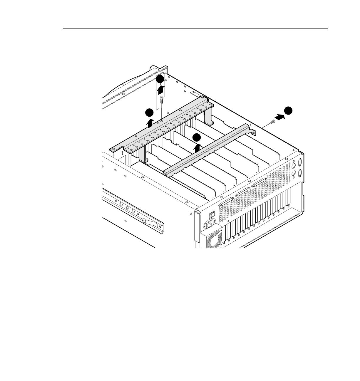
Figure 1 shows ch assis cover screws for a PDR200. On a PDR100, the screws in
the center of the t op fr ont cover may no t be pre sent. To remove the cha ssis c overs:
NOTE: Take care not to lose these chassis scre ws. They are require d to meet
the EMI sp e cificati o n s f o r the P r o f il e sys t e m.
1. Turn Profile system power off and deta ch the power co rd.
2. Loosen the front panel retaining screw and pull the chassis out of the rack
until the slide stop latc hes engage.
3. Use the Torx tool with the T10 tip to remove the front chassis cover (
Figure 1) which covers the fans and disk drives. The front cover must be
removed first because it overlaps the rear cover.
4. Use the Torx tool with the T10 tip to remove the rear chassis cover (
Figure 1) which covers the circuit boa rds.
12 Analog Composite I/O Installation
Ë
Ê
in
in
Page 13

9675-9
Removing the Chassis Covers
2
1
Figure 1. Removing the Top Covers
Analog Composit e I/O Ins tallation 13
Page 14

Analog Composite I/O Installation
Removi ng Hold-downs
There are two hold-down brackets loc a ted in the circuit board area that must be
removed in order to remove and replace circuit boards. Figure 2 shows these
brackets.
To remove the hold-down brackets:
1. Use the Torx tool with the T10 tip to remove the screw (
secures the rear h old-down bracket.
2. Lift the hold-down bracket (
it asi d e.
3. Use the Torx tool with the T10 tip to remove the screw (
secures the front hold-down bracket.
4. Lift the hold-down bracket (
it asi d e.
in Figure 2) up and out of the chassis a nd set
Ë
in Figure 2) up and out of the chassis a nd set
Í
in Figure 2) which
Ê
in Figure 2) which
Ì
14 Analog Composite I/O Installation
Page 15
Removing Hold-downs
3
4
2
9675-2
Figure 2. Removing the Circuit Board Hold-downs
1
Analog Composit e I/O Ins tallation 15
Page 16

Analog Composite I/O Installation
Removing Circuit Boards
Installing the Analo g Composite I/O board may require that you remove or
reposition one or more currentl y inst alled boards to make room for the new board
or to meet internal c abling constraints. Whe n unplugging boards you may als o find
it necessary to remove the screw mount ing an adja cent circuit board, and in the
case of some short ci rcuit boa rds, it might be neces sary t o remove an adja cent tall
circuit board to ease removal of the shorter board.
Use the following procedure to unplug a circuit board from the motherboard.
NOTE: Make a note or diagram of cable connections prior to removal to
facilitate reinstallation.
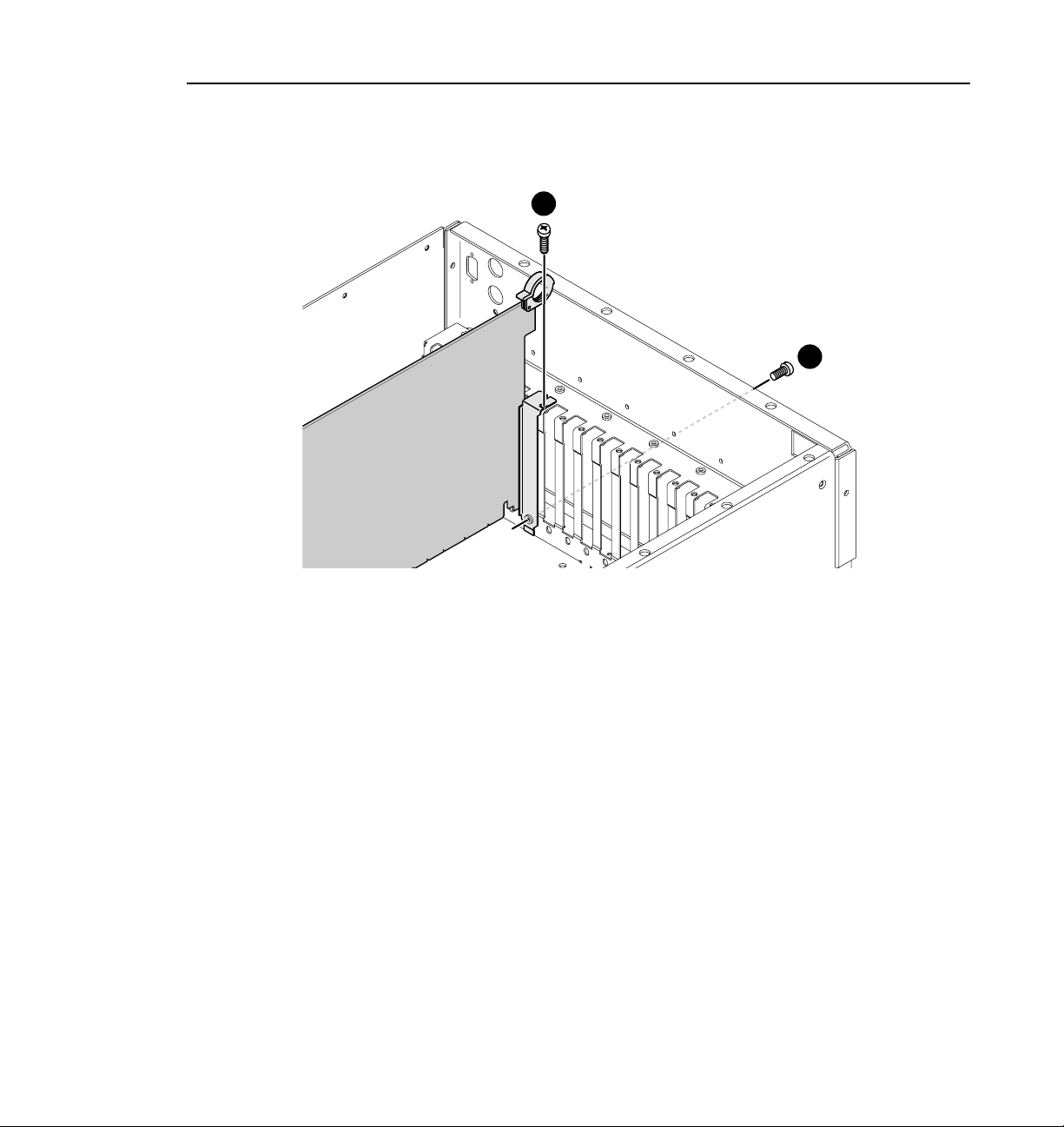
1. Remove all inte rior and rear panel cables fro m the circuit boar d that is to be
removed.
2. Use the Torx tool with the T15 tip to remove the screw from the bracket
inside the chassis (
outside the chassis (Ë in Figure 3).
CAUTION: To avoid damage to the circuit board when removing or
!
installing it:
in Figure 3) and the screw through the rear panel
Ê
• Do not rock the circuit boar d in the EISA Bus connector — pull straight up
to remove.
• Do not grasp or push on the rear-panel connectors when removing or
installing a circuit board in a card slot.
3. Extract the circuit boa rd. If the circuit board is tall, use the extraction lever
on the front of the board and the extraction ring at the back of the board to
lift the circuit board f ree of the connectors on the motherboard.
For short circu it boards, carefull y gras p the boa rd and lif t upward t o free the
circuit board from the motherboard connectors. You might need to remove
an adjacent tall board to get enough room for a safe hold on the boar d.
16 Analog Composite I/O Installation
Page 17
Removing Circuit Boards
1
Figure 3. Screw Locations for a Board Bracket
2
9040-13
Analog Composit e I/O Ins tallation 17
Page 18

Analog Composite I/O Installation
Board Location Guide
This board location guide ide ntifies the inputs and outputs of each Profi le board
currently avail able for a PDR100 or PDR200, as well as the input and output
connections on the Video Router connectors on the motherboard. Use this
information when:
• you add a new circuit board to the Profile system and need to select a slot
into which you can install it;
• you need to move boards around to meet requirements for new boards.
As you move boards around, remember that some circuit boards must occupy
specific slots , while others can be installed in almost any slot a s long as their I/O
requirements are met.
This section provides a simple approach to board location. It explains the
relationship bet ween the motherboa rd and Video Router connect ors and provide s
tables, charts and examples to as sist you in installing boards.
Video Router to Motherboard Relationship
The Video Router provides and controls video data to twelve connectors on the
motherboard. These video dat a connectors are align ed with the main motherboard
connectors for slo ts J5 through J16. Since the Ref Gen board must occupy J16 to
provide the necessary system clocks, this discussion excludes J16.
When choosing a slot for a board, the major constraint on a slot is how the boar d
connects to the Video Router. Not all boa rds requir e the same nu mber of video I/O
connections, and not all video data connectors provi de the same number of vi deo
I/O connections. Therefore, you must know how many input and output
connections the board need s, and the slot(s) available that meets tho se needs.
Board I/O Requirements and Restrictions
Table 1 lists each of the boards which may be instal le d in the Profile system and
the recommended slots, possible alternatives, and restrictions for each board.
Note that if more than one slot is recommended or possible for a board, those slots
are listed in the order of preference.
18 Analog Composite I/O Installation
Page 19

Table 1. Board I/O Requirements and Restrictions
Board Location Guide
Board Video Router
connection
requirements
Inputs Outputs PDR 100 PDR 200
CPU none n/a J1 J1 none
VGA n/a n/a J2 J2 none
LAN n/a n/a J3 J3 none
SCSI n/a n/a J4 J4 none
RefGen n/a n/a J16 J16 none
RS422 n/a n/a J17 J17 none
FibreChannel n/a n/a J15 J8 J5-J15 Must be adjacent to Mast er EDR
Master EDR 2 2 J14 J9 J5-J15 Must be adjacent to Slave EDR
Slave EDR 2 2 J13 J10 J5-J15 Must be adjacent to Master EDR
Master DR 2 2 J14 n/a J5-J15 Must be in adjacent to Slave DR
Slave DR 2 2 J15 n/a J5-J15 Must be adjacent to Master DR
Serial Digital
I/O
Decoder None None J8 J5 J7, J11 Must be adjacent to Analog
Analog
Composite In
Analog
Composite I/O
Mix Effects 6 2 J7 J7 J6 Only J6 and J7 have 5 inputs;
4 Ch. Analog
Out
Analog
Composite
Monitor
Audio Signal
Processing Bd
(ASPB)
CAV In None 1 J5 J5 J5-J15
Audio I/O None None J5-J15 J5-J15 J5-J15
2 2 J11 J14, J15 J11, J5,
None 1 J9 J6 J8, J12 Must be adjacent to Decoder
2 2 J11 J14, J15 J11, J5,
4 None J6 J6 J12, J7,
4 None J12 J12 J6, J7,
None None J13 J13 J5-J15
Slot Recommended Other
Possible
Slots
J11
J11
Restrictions
and (if installed) Fibre Channel
Can’t go in J5 if Mix Effects is in
J7
J6 or in J8 if Mix Effect s is i n J7
Composite In
Can’t go in J5 if Mix Effects is in
J7
J6 or in J8 if Mix Effect s is i n J7
board must be able to get a
shared input (the 6th) from an
adjacent slot (J5 or J8)
Only J6, J7 , J11, an d J1 2 hav e 3
(or more) inpu ts. I f in J11 or J12,
board must be able get a shared
input (the 4th) fr om an a djacent
slot (J10 or J13)
Only J6, J7 , J11, an d J1 2 hav e 3
(or more) inpu ts. I f in J11 or J12,
board must be able get a shared
input (the 4th) fr om an a djacent
slot (J10 or J13)
Analog Composit e I/O Ins tallation 19
Page 20

Analog Composite I/O Installation
Video Router I/O Connections
Now let’s look at the Vide o Router connections a vailable at slots J5-J15. Table 2
is a board location chart with the Video Router input and output connections. In
the table:
• The Slots column lists each slot on the motherboard connected to the Video
Router.
• The Board column is where you e nter the boards currently installed and the
name of the board you want to install.
• The Inputs column identifi es data input connections to the slots (boards)
from the Video Router. The numbers in the blocks correspond to the order
input connections are assigned at the Video Router connector.
• The Outputs column identifies data output connections from the slots
(boards) to the Video Router. The numbers in the blocks correspond to the
order output connecti ons are assigned at the Video Router connector.
• The shaded blocks in the d iagram indicate Video R outer conn ections sha red
between slots. A shar ed connec tion is avail abl e to eithe r slot, but not both a t
the same time.
For instance :
• The shaded blocks between slots J5 and J6, slots J7 and J8, slo ts J10 and J11,
and slots J12 and J13 indicate shared input connections.
• The shaded blocks between slots J8 and J9, slots J10 and J11, and slots J12
and J13 indicate shared output c onne ctions.
20 Analog Composite I/O Installation
Page 21

Table 2. Boar d Loca tio n Ch art
Board Location Guide
Slot Board Inputs
J5
1
2
J6
1
2
J7
3
4
5
6
J8
1
J9
2
1
J10
2
J11
1
J12
2
3
4
J13
J14
1
2
J15
1
2
6
5
4
3
2
1
2
1
4
3
2
1
2
1
Outputs
1
2
3
1
2
1
2
3
4
1
2
3
4
1
2
3
4
1
2
3
1
2
3
2
1
4
3
2
1
4
3
2
1
4
3
2
1
Analog Composit e I/O Ins tallation 21
Page 22

Analog Composite I/O Installation
Selecting a Location
Here’s how to use the tables to select a location for a board.
1. In the Board Location Char t, Table 2, enter the board na me and, refe rring to
Board I/O Requi rements a nd Rest rictions, Table 1, put a check mark in ea ch
input and output block u sed by each board currently inst alle d in your Profil e
syst e m. Sta rt wi th th e 1 block for each board.
2. Look in the Board I/O Requirements and Restrictions, Table 1, to see the
input and output requirements and both the recommended slot and
alternative slots for the board you want to install.
3. Look in the Boar d Location Char t, Table 2, for a slot wi th the required Video
Router connections ava ilable. Starting with the 1 block, put an “X” in each
block that corresponds to an input and output requirement for the board. If
the recommended slot is occupied, or there are not enough input or output
blocks avail abl e, lo ok at the al te rnat iv e slo ts.
4. If all input and output require ments f or the board match the available ones
for the slot , write the b oard name in the Boa rd column for the slot and in stall
the board.
NOTE: If you ca n’ t find an ope n slot wit h t he I/O which meet s the I/O
requirements of the board you want to instal l, y ou will have to move boards
around. You can use the Boa rd I/O Requiremen ts and Restri ction s table an d
the Board Locat ion Chart to experiment with various board locations before
deciding on one.
The following examples de monstrate how to u se the Board I /O Requirements and
Restrictions , Tabl e 1, and the Board Location Chart, Table 2.
22 Analog Composite I/O Installation
Page 23

Board Location Guide
Example 1
This example shows how to use the Board I/O Requirements and Restrictions,
Table 1, and the Board Location Chart, Tab le 2, to install an Analog Composite
I/O board into a 4-channel PDR200 with Fibre Channel and Mix Effects.
1. Fill in the Board Location Chart with the information for all the boards
currently installed in the system.
a. For the Mix Effects in slot J7, which requires six inputs and two outputs:
- Put check marks in the five J7 Input blocks, 1-5.
- Put a check mark in the J8 shared Input Block.
- Put check marks in the J7 Output blocks 1 and 2.
b. For the Fibre Channel in slot J8 - no Video Router I/O requir ements
c. For the Master EDR in slot J9, which r equires two in puts and two outpu ts,
put check marks in the J9 I nput blocks 1 and 2 and in the J9 Output block s
1 and 2.
d. For the Slave EDR in slot J1 0, which requir es two inputs and two outp uts,
put check marks in the J10 Input blocks 1 and 2 and in the J10 Output
blocks 1 and 2.
e. For the ASPB in slot J13 - no Video Router I/O requirements
f. For the Serial Digital I/O in slots J14 and J15, which both require two
inputs and two outputs, put che ck marks in both J14 an d J15 Input bl ocks
1 and 2 and in J14 and J15 Output blocks 1 and 2.
2. From the Board I/O Requirements and Restrictions table, note that the
Analog Composite I/O board requir es two inputs and two outputs and that
the first reco mmended slot is J14, the se cond recommended sl ot is J1 5, wit h
J11, J5, and, J7 as other possible slots.
3. Looking at your Board Location Chart , you see tha t:
- The first recommended slot, J14, is occupie d.
- The second recommended slot, J15, is also occupied.
- The first other possible slot, J11 is open.
4. On your Board Location Chart, put Xs in the J11 Input blocks 1 and 2 and
the Output blocks 1 and 2.
Analog Composit e I/O Ins tallation 23
Page 24

Analog Composite I/O Installation
5. Write Analog Composite I/O in the Boards column for slot J11 and install
the board.
Your Board Location Chart would then look similar to Table 3: Example 1.
24 Analog Composite I/O Installation
Page 25

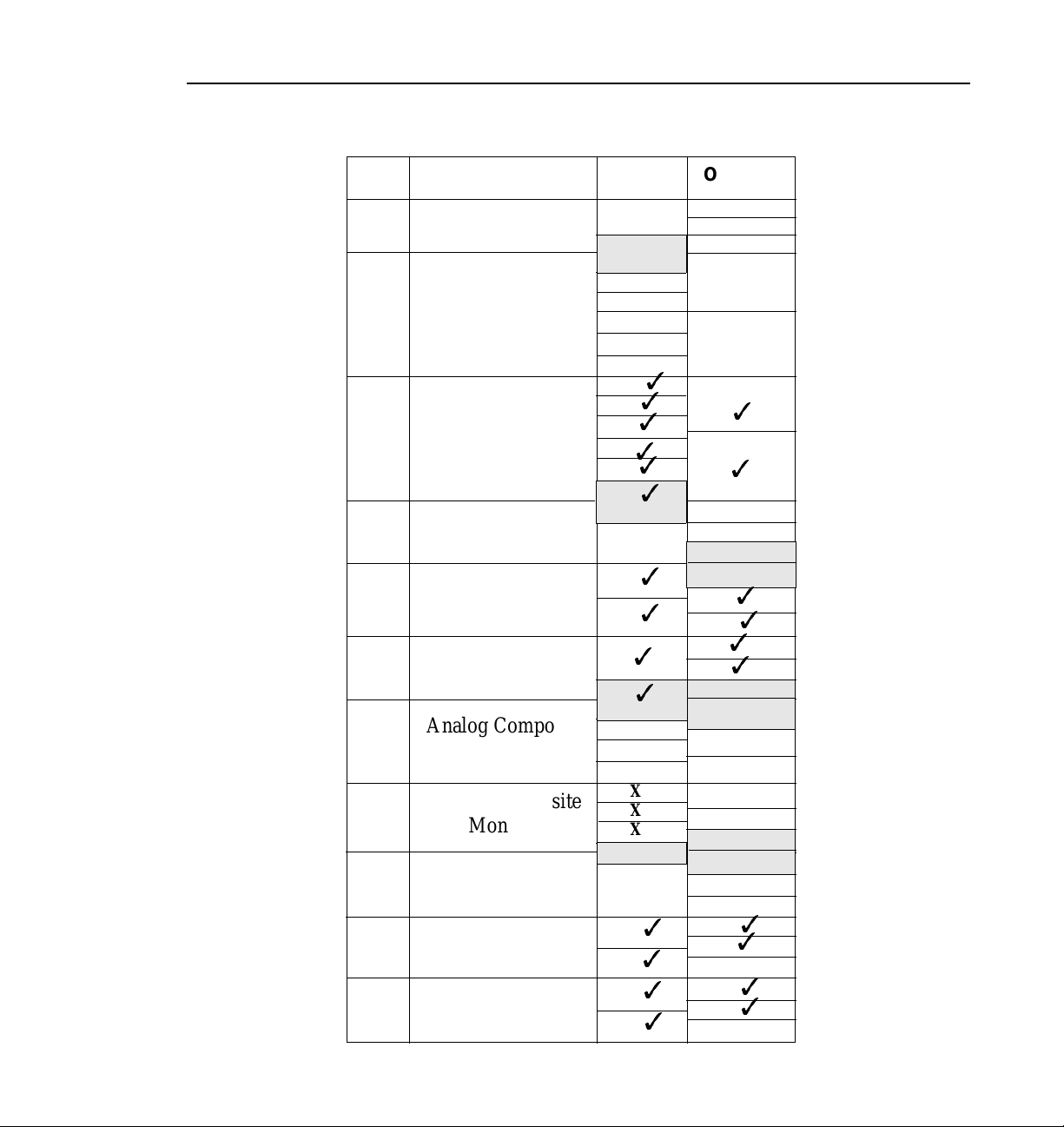
Board Location Guide
Table 3: Example 1 - Installing an Analog Composite I/O Board
Slot Board Inputs
J5
1
2
J6
3
1
3
2
3
3
4
3
3
5
6
3
1
3
2
3
1
3
2
3
X
X
1
2
3
4
1
3
2
3
1
3
3
2
J7
J8
J9
J10
J11
J12
J13
J14
J15
Mix
Effects
Fibre Channel
Master Enhanced
Disk Recorder
Slave Enhanced
Disk Recorder
Analog Composite
I/O
ASPB
Serial Digital I/O
Serial Digital I/O
6
5
4
3
2
1
2
1
4
3
2
1
2
1
Outputs
1
2
3
1
3
2
3
1
2
3
4
3
3
3
1
2
3
3
4
X
X
1
2
3
4
1
3
3
2
3
3
1
2
3
3
2
1
4
3
2
1
4
3
2
1
4
3
2
1
Analog Composit e I/O Ins tallation 25
Page 26

Analog Composite I/O Installation
Example 2
If you next want to install an Analog Composite Monitor board:
1. From the Board I/O Requirements and Restrictions table, note that the
Analog Composite Monitor board requires four inputs and no outputs and
that the first recommended slot is J12 with slots J6, J7, and J11 as other
possibilities.
2. Looking at your Board Location Chart , you see tha t slot J12 is open and
although it only ha s 3 Inputs, the 4th Input can be the input shared with J13
because the ASPB is not using it.
3. On your Board Location Chart, put Xs in the 1, 2, and 3 J12 Input blocks and
in the J13 shared Input block.
4. Write Analog Composite Monitor in the Boar d column for slot J12 and
install the board.
Your Board Location Chart would then look similar to Table 4: Example 2.
26 Analog Composite I/O Installation
Page 27
Board Location Guide
Table 4: Example 2 - Installing an Analog Composite Monit or Board
Slot Board Inputs
J5
1
2
J6
3
1
3
2
3
3
4
3
3
5
6
3
1
3
2
3
1
3
2
3
X
X
X
1
2
X
X
3
X
4
1
3
2
3
1
3
3
2
J7
J8
J9
J10
J11
J12
J13
J14
J15
Mix
Effects
Fibre Channel
Master Enhanced
Disk Recorder
Slave Enhanced
Disk Recorder
Analog Composite
I/O
Analog Composite
Monitor
ASPB
Serial Digital I/O
Serial Digital I/O
6
5
4
3
2
1
2
1
4
3
2
1
2
1
Outputs
1
2
3
1
3
2
3
1
2
3
4
3
3
3
1
2
3
3
4
X
X
1
2
3
4
1
3
3
2
3
1
3
2
3
3
2
1
4
3
2
1
4
3
2
1
4
3
2
1
Analog Composit e I/O Ins tallation 27
Page 28

Analog Composite I/O Installation
Audio Clock Cabling
This section provides some general rules about audio clock cabling when either an
ASPB or an Audio I/O board is installe d. Audio clock signals from the appropriate
video board synchroniz e the audio to the video during Record. Internal cabling
between connectors on the top of the video boards and connectors on the top of the
audio boards provide the clock signals to the audio boards.
ASPB Audio Clock Cabling
The ASPB provides for input of four audio clock signals to audio banks
Audio 1-Audio 4, where each bank consists of four audio channels. Audio clock
signals from video boards are prioritized by the slot locations of the video boards,
going from slot J5 to slot J15. ASPB Audio 1-Audio 4 connectors begin closest to
the rear panel and go toward the front.
In general, th e video board in the lowest num bered slot m ust provide the audio clock
signal to the Audio 1 bank, the video board in the next lowest numbered slot must
provide the audio clock signal to the Audio 2 bank, etc. For example, if you have
video boards in slots J5 and J11, the audio clock signal from the one in J5 must be
connected to Audio 1 on the ASPB and the a udio clock signal from the video board
in slot J11 must be connected to Audio 2 on the ASPB.
Figures 4 and 5 show examples of internal audio clock cabling with the ASPB. In
Figure 4, Analog Composite I/O boards, installed in slots J14 and J15, are the only
video boards. The audio clock cable connections are:
• Channel A of the board in slot J14 to Audio 1 on the ASPB in slot J13
• Channel B of the board in slot J14 to Audio 2 on the ASPB in slot J13
• Channel A of the board in slot J15 to Audio 3 on the ASPB in slot J13
• Channel B of the board in slot J15 to Audio 4 on the ASPB in slot J13
Note that Figure 4 is an example with video boards only in sl ots J14 and J15. If you
have other video boards in lower numbered slots, you will have to determine how
you want to set your system up. You will have to remove any unused clock cabl es
and you may have to move boards around to accommodate your setup.
28 Analog Composite I/O Installation
Page 29
Audio Clock Cabling
Ch. B
Ch. A
Composite I/O
Figure 4. Example of Audio Clock Cabl ing i n a PDR204A
Audio 4
Audio 3
Audio 2
Audio 1
ASPBAnalog
0044-2
Analog Composit e I/O Ins tallation 29
Page 30

Analog Composite I/O Installation
In Figure 5, the Analog Composite I/O board install ed in slot J11 makes it the firs t
video board, going from J5 to J15, and the Serial Digital I/O board becomes the
second video board. You would have to move the Serial Digital I/O audio clock
cables from the AS PB Audio 1 and Audio 2 connectors t o, respectively, the Audio
3 and Audio 4 connectors. Audio clock cable connections are then:
• Analog Composite I/O Channel A to ASPB Audio 1
• Analog Composite I/O Channel B to ASPB Audio 2
• Serial Digital I/O Channel 1 to ASPB Audio 3
• Serial Digital I/O Channel 2 to ASPB Audio 4
Bear in mind that the ASPB only provid es for input of four audio clock si gnals
and note the following:
a. Figure 5 is an example of a 2-channel PDR 200 with one Serial Digital
I/O board.
b. If you have a 4-channel PDR200 with two Serial Digital I/O boards, all
four ASPB audio clock inputs will be connect ed.
c. If you then want to install an Analog Composite I/O board, you will have
more audio clock signals than you have connectio ns on the ASPB (two from
the Analog Composite I/O board and four from the two Seri al Digital I/O
boards).
You will have to determine how you want to set your system up, that is, what
you want as the video sources of the audio clocks for the Audio 1-Audio 4
banks of audio channels. You will have to remove any unused audio clock
cables and you may have to move boards around to accommodate your
desired system setup.
30 Analog Composite I/O Installation
Page 31
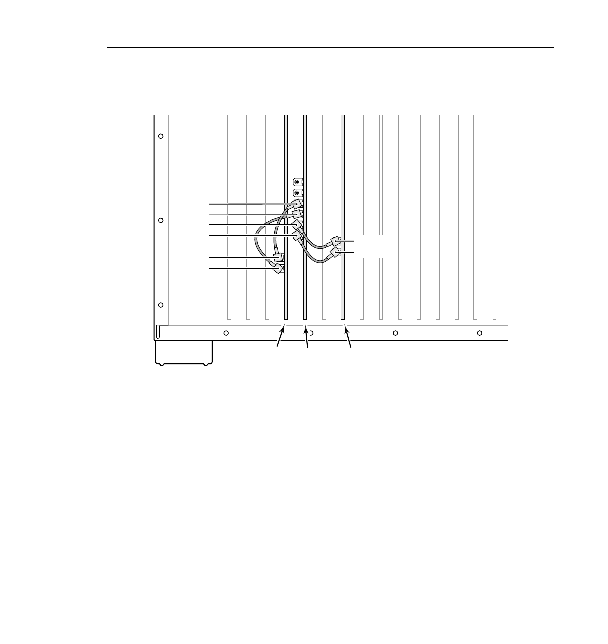
Audio 4
Audio 3
Audio 2
Audio 1
Ch. 2
Ch. 1
Digital I/O
ASPBSerial
Audio Clock Cabling
Ch. B
Ch. A
0044-3
Analog
Composite I/O
Figure 5. Example of Audio Clock Cabl ing i n a PDR202D
Analog Composit e I/O Ins tallation 31
Page 32

Analog Composite I/O Installation
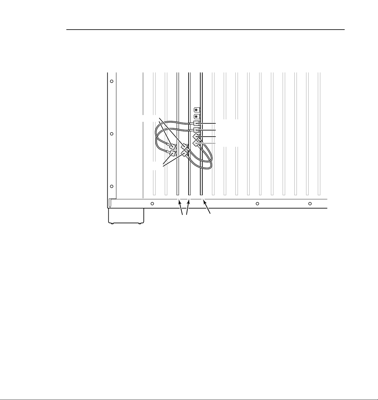
Audio I/O Audio Clock Cabling
Figure 6 shows an example of an Analog Composite I/O board installation in a
PDR100 with two Audio I/O boards inste ad of an ASPB. In the Figure 6, audio clock
cable connect io n s are fro m:
• Analog Composite I/O Channel A to the RECORD connector on the Audio I/O
board in the lowest numbered slot fr om slot J5 to slot J15.
• Analog Composite I/O Channel B to the RECORD connector on the Audio I/O
board in the next lowest slot.
• PLAY connectors on both Audio I/O boards to any of the syste m clocks on the
RefGen board, or to any boar d which has system clock c onnec tors (such as the
Analog Composite Output board).
Figure 6 is an example only. If you hav e other vide o boards insta lled, you will have
to determine which video source you want to use for the audio clock signals and
make Audio I/o board connection adju stments accordingly.
32 Analog Composite I/O Installation
Page 33

Play Cables
Record Cables
Audio Clock Cabling
Ch. B
Ch. A
Ref Gen Analog
Figure 6. Example of Audio Clock Cabling Wit h an Audio I/O Board
Audio
2 or 4
Audio
1 or 3
Composite I/O
Analog Composit e I/O Ins tallation 33
0044-4
Page 34

Analog Composite I/O Installation
Installing the Analog Composite I/O Board
Refer to the “Board Location Guide” beginning on p age 10 and inst all the Analog
Composite board as follows:
1. If necessary, remove the slot cover where you want to install the board.
2. Align the board with the connectors on the motherboard. Make sure the
extractor on the front en d of the board is in the up position, then press down
on the board f irmly until the board is seated. As you push the board into the
connectors, you will feel the board engage first one, then a second set of
contacts in the connector. The board is properly seated when the top of the
rear mounting bracket is resting on the rear chassis wall shelf.
3. Use the Torx tool with the T15 tip to install the mounting screws in the top
of the bracket inside the chassis (
at the bottom of the bracket (
1
in Figure 7) and through the rear panel
Ê
in Figure 7).
Ë
Figure 7. Screw Locations for Board Mounting Bracket
34 Analog Composite I/O Installation
2
9040-13
Page 35

Installing the Analog Composite I/O Board
4. Install th e blank circ uit boar d brackets ( if necessa ry) in t he empty boar d slots
on the rear panel.
5. Refer to “Audio Clock Cabling” beginning on page 20 and connect audio
clock cables f rom the Analog Composite I/O board to the appropria te clock
connectors on the ASPB or the RECORD connectors on the Audio I/O
boards.
6. Use the Torx tool with the T10 tip to reinstall the rear board hold-down
bracket (see Figure 2, page 7).
CAUTION: To prevent damage to the Monitor boar d, a short board extension
on the front hold-down bracket must not be installed at the Monitor board
location.
7. If necessary, reconfigure the front board hold-down, moving or removing
short board extensions.
8. Use the Torx tool with the T10 tip to reinstall the front board hold-down
bracket (see Figure 2, page 7).
9. Use the Torx tool with the T10 ti p to r einstall the rear top c over and t hen the
front top cover.
10.Apply the stick-on labels at the appropriate location in the Profile chassis
rear panel to identify the locat ion of the Analog Composite I/O board and
any board you repositioned .
11.Reinstall the Profile chassis in the rack and reconnect all cables previously
removed. Before attaching c ables to the BNC connectors, install the mesh
washers as shown in Figure 8.
Figure 8. Installi ng Mesh Washers
Analog Composit e I/O Ins tallation 35
Page 36

Analog Composite I/O Installation
12. Install mesh washers (Figure 8) and connect analog composite input and
output cables to the Analog Composite I/O board. See Figure 9 for an
example.
Note that the S-video In connector allows you to connect an S-video device
to the Analog Composite I/O board. However, the S-video device takes the
place of one of the inputs (either In A or In B). Time Base Correction is
possible on only one input at a time.
J17 J13J16
J15 J14 J6J7
Analog Composite
Figure 9. Analog Composite I/O Cable Connect ions Example
J11 J9
J12
J10
Video I/O
J8
In A
In B
S-video In
Out A
Out B
J5
J4 J3 J2
J1
0044-1
13. Apply power to the Profile system and start the Profile Configuration
Manager application. Check the graphic representation of the Profile rear
panel. It should indicate the presence of the Analog Composite I/O board in
the slot where you installe d the board.
14. Configure the system for the Analog Composite I/O board as instructed in
the Profile Family User Manual.
36 Analog Composite I/O Installation
 Loading...