

Page 1

Instruction Manual
Profile Family
CD-ROM
Tektronix, Inc.
PO Box 1000
Wilsonville, OR 97070-1000 USA
1-800-547-8949 (USA and Canada)
1-503-682-7300
http://www.tektronix.com
Page 2

Copyright Copyright 1998 Tektronix, Inc. Wilsonville, Oregon.
Printed in the United States of America or the United Kingdom. All rights
reserved. This document may not be copied in whole or in part, or otherwise
reproduced except as specifically permitted under U.S. copyright law, without
the prior written consent of Tektronix, Inc., P.O. Box 1000, Wilsonville,
Oregon 97070-1000 USA.
Trademark Notices TEKTRONIX ,TEK, and Profile are registered trademarks of Tektronix, Inc.
Other trade names used in this document are trademarks or registered
trademarks of the manufacturers or vendors of the associated products.
Revision Status
Rev Date Description
March 1997 Original Issue. Manual part number 070-9897-00.
November 1998 Revised to include PDR200 & PDR300 installation, roll
P/N to 070-9897-01
Page 3

Contents
Tektronix Product Support .......................................................................................... 5
General Safety Summary ........................................................................................... 6
Service Safety Summary ............................................................................................ 11
Introduction.................................................................................................................. 13
List of CD-ROM Drive Installation Procedures.................................................... 13
Kit Contents......................................................................................................... 14
Tools Required.................................................................................................... 14
Sharing the CD-ROM Drive On the Network....................................................... 15
Upgrading Windows NT....................................................................................... 15
Upgrading Windows NT 3.50....................................................................... 15
Upgrading Windows NT 3.51....................................................................... 16
Installing Windows NT Service Packs ......................................................... 16
General Installation Instructions.................................................................................. 17
PDR200, PDR300, and PDR400 Installation ............................................................. 18
Connecting the CD-ROM Drive........................................................................... 18
Installing the CD-ROM Driver In Windows NT 4.0............................................... 19
Removing the CD-ROM Drive............................................................................. 20
PDR200, PDR300 and PDR400 Troubleshooting...................................................... 21
Checking the Windows NT CD-ROM Device Status........................................... 21
Checking the Parallel Port Status........................................................................ 22
Running Load CMOS to Configure the Parallel Port........................................... 23
Setting VGA-I/O Board Switches to Configure the Parallel Port.......................... 23
PDR100 Installation .................................................................................................... 29
Determining the System CPU Board Hardware Version..................................... 29
Installing the Parallel Port.................................................................................... 32
Removing the Top Covers........................................................................... 32
Verifying Switch Settings On the VGA-I/O Board (if installed)..................... 34
Installing the Parallel Port L-bracket............................................................ 39
Enabling the System CPU Board Parallel Port............................................ 40
Connecting the CD-ROM Drive to the PDR100 .................................................. 42
Installing the Windows NT CD-ROM Driver......................................................... 44
Installing the CD-ROM Driver in Windows NT 3.51..................................... 44
Installing the CD-ROM Driver in Windows NT 4.0....................................... 45
Removing the CD-ROM Drive............................................................................. 47
Removing the CD-ROM Driver From Windows NT 3.51 ............................. 47
Removing the CD-ROM Driver From Windows NT 4.0 ............................... 48
CD-ROM Instructions 3
Page 4

Contents
PDR100 Troubleshooting............................................................................................ 49
Checking the Windows NT Device Status ........................................................... 49
Checking the CD-ROM Device Status In Windows NT 3.51........................ 49
Checking the CD-ROM Device Status In Windows NT 4.0.......................... 50
Checking the Parallel Port Status........................................................................ 50
Checking the Parallel Port Status In Windows NT 3.51............................... 50
Checking the Parallel Port Status In Windows NT 4.0................................. 51
Verifying the Parallel Port Configuration.............................................................. 52
Verifying the VGA-I/O Board Configuration Switches.................................. 52
Figures
1 CD-ROM drive cabling for the PDR200, PDR300, and PDR400 .............. 18
2 Removing the circuit board retainer........................................................... 24
3 Location of circuit board mounting screw................................................... 25
4 CEX595 VGA-I/O board switch settings to enable parallel port................. 26
5 CEX585 VGA-I/O board switch settings to enable parallel port................. 27
6 Removing the top covers........................................................................... 33
7 PDR100 VGA board with and without a parallel port................................. 34
8 CEX595 VGA-I/O board switch settings when used with
the 486 System CPU board............................................................... 35
9 CEX585 VGA-I/O board switch settings when used with
the 486 System CPU board.............................................................. 36
10 Removing the circuit board retainer........................................................... 37
11 Location of circuit board mounting screw................................................... 38
12 Installing the parallel port L-bracket and cabling........................................ 39
13 Removing the top covers........................................................................... 53
14 Removing the circuit board retainer........................................................... 54
15 Location of circuit board mounting screw................................................... 55
16 CEX595 VGA-I/O board switch settings when used with
the Pentium System CPU board........................................................ 56
17 CEX585 VGA-I/O board switch settings when used with
the Pentium System CPU board........................................................ 57
Tables
1 List of CD-ROM drive installation procedures ........................................... 13
2 Procedure selection table ........................................................................ 30
3 Procedures to enable parallel port settings in CMOS ............................... 41
4 Connecting the CD-ROM drive to the PDR100 parallel port .................... 43
5 Instructions for verifying parallel port configuration ................................... 52
4 CD-ROM Instructions
Page 5

Tektronix Product Support
You can get technical assistance, check on the status of problems, or report new
problems by contacting our Product Support Group.
United States and Canada
Monday–Friday 5:30AM–5:00PM Pacific Time
(800) 547-8949
Europe
Monday–Friday 9:00AM–5:30PM
Austria 02236-8092-400 Netherlands 0513-656395
Belgium 02-715-89-92 Norway 22-07-07-15
Denmark 44-85-07-06 Spain 091-3726050
Finland 0947-834205 Sweden 08-4776597
France 01-69-86-83-45 Switzerland 041-72-93-625
Germany 0221-9477-444 United Kingdom 01628-405810
Italy 02-25086600 Other 44-1628-405817
Email: EuroProfile@tektronix.com
Asia and South America
Australia 61-2-888-7066 Korea 82-2-528-5299
Brazil 55-11-543-1911 Mexico 52-5-666-6333
Hong Kong 852-2585-6688 Singapore 65-356-3900
Japan 81-3-3448-3111 Taiwan 886-2-765-6362
World Wide
24-hour Emergency Hotline (503) 685-2345 (Contract and warranty customers)
World Wide Web http://www.tektronix.com/VND/Support
FTP Site ftp.tektronix.com
Email ProfileSupport@tektronix.com
Users Group profile-users@tektronix.com
CD-ROM Instructions 5
Page 6
General Safety Summary
General Safety Summary
!
!
Injury Precautions
Use Proper Power
Cord
Anchor Equipment
Rack
Do Not Operate
Without Covers
WARNING: These instructions are for use by qualified
service personnel only. To avoid personal injury, do not
perform any servicing unless you are qualified to do so.
Refer to all safety summaries before performing service.
Review the following safety precautions to avoid injury and
prevent damage to this product or any products connected to
it.
While using this product, you may need to access otherparts
of the system. Read the General Safety Summary in other
system manuals for warnings and cautions related to
operating the system.
To avoid fire hazard, use only the power cord specified for
this product.
To prevent serious injury, insure that the equipment rack is
anchored to the floor so that it cannot tip over when the
Profile Video File Server is extended out of the rack
To avoid electric shock or fire hazard, do not operate this
product with covers or panels removed.
Do Not Operate In
Wet/Damp
Conditions
Do Not Operate In
An Explosive
Atmosphere
6 CD-ROM Instructions
To avoid electric shock, donot operate thisproduct inwet or
damp conditions.
To avoid injury or fire hazard, do not operate this product in
an explosive atmosphere.
Page 7
Product Damage Precautions
Product Damage Precautions
Use Proper Power
Source
Provide Proper
Ventilation
Do Not Operate With
Suspected Failures
Do not operate this product from a power source that applies
more than the voltage specified.
To prevent product overheating, provide proper ventilation.
If you suspect there is damage to this product, have it
inspected by qualified service personnel.
Safety Terms and Symbols
Terms in This
Manual
!
!
!
!
Terms on the
Product
These terms may appear in this manual:
WARNING: Warning statements identify conditions or
practices that can result in personal injury or loss of life.
CAUTION: Caution statements identify conditions or
practices that can result in damage to the equipment or other
property.
These terms may appear on the product:
DANGER indicates a personal injury hazard immediately
accessible as one reads the marking.
WARNING indicates a personal injury hazard not
immediately accessible as you read the marking.
CAUTION indicates a hazard to property including the
product.
CD-ROM Instructions 7
Page 8
General Safety Summary
Symbols on the
Product
!
!
The following symbols may appear on the product:
DANGER high voltage
Protective ground (earth) terminal
ATTENTION – refer to manual
8 CD-ROM Instructions
Page 9

Certifications and Compliances
Certifications and Compliances
Canadian Certified
Power Cords
Canadian Certified
AC Adapter
FCC Emission
Control
Canadian approval includes the products and power cords
appropriate for use in the North America power network. All
other power cords supplied are approved for the country of
use.
Canadian approval includes the AC adapters appropriate for
use in the North America power network. All other AC
adapters supplied are approved for the country of use.
This equipment has been testedand foundto complywith the
limits for a Class A digital device, pursuant to Part 15 of the
FCC Rules. These limits are designed to provide reasonable
protectionagainst harmful interference whenthe equipment is
operated in a commercial environment. This equipment
generates, uses,and can radiate radio frequency energy and,if
not installed and used in accordance with the instruction
manual, may cause harmful interference to radio
communications. Operation of thisequipment ina residential
area is likely to cause harmful interference in which case the
user will be required to correct the interference at his own
expense. Changesor modifications not expressly approved by
Tektronix can affect emission compliance and couldvoid the
user’s authority to operate this equipment.
CD-ROM Instructions 9
Page 10

General Safety Summary
Canadian EMC
Notice of
Compliance
EN55022 Class A
Warning
This digital apparatus does not exceed the Class A limits for
radio noise emissions from digital apparatus set out in the
Radio Interference Regulations of the Canadian Department
of Communications.
Le présent appareil numérique n’émet pas de bruits
radioélectriques dépassant les limites applicables aux appareils
numériques de la classe A préscrites dans le Règlement sur le
brouillage radioélectrique édicté par le ministère des
Communications du Canada.
For products that comply with Class A. In a domestic
environment this product may cause radio interference in
which case the user may be required to take adequate
measures.
10 CD-ROM Instructions
Page 11

Service Safety Summary
Service Safety Summary
!
!
Do Not Service
Alone
Disconnect Power To avoid electric shock, disconnect the main powerby means
Use Care When
Servicing With
Power On
WARNING: These instructions are for use by qualified
service personnel only. To avoid personal injury, do not
perform any servicing unless you are qualified to do so.
Refer to all safety summaries before performing service.
Do not perform internal service or adjustment of this product
unless another person capable of rendering first aid and
resuscitation is present.
of the power cord. or, if provided, the power switch.
Dangerous voltages or currents may exist in this product.
Disconnect power and remove battery (if applicable) before
removing protective panels, soldering, or replacing
components.
To avoid electric shock, do not touch exposed connections
CD-ROM Instructions 11
Page 12

Service Safety Summary
12 CD-ROM Instructions
Page 13

CD-ROM Instructions
Introduction
These instructions explain how to temporarily install the CD-ROM drive on your
Profile system. Once you have installed the CD-ROM drive, you can perform
software upgrades, such as upgrading the Windows NT operating system (see
“Upgrading Windows NT” on page 15) or upgrading the Profile system software.
You can find instructions for upgrading Profile system software in the Profile
Software Release Notes.
Topics discussed in the section include:
- List of CD-ROM Drive Installation Procedures
- Kit Contents
- Tools Required
- Sharing the CD-ROM Drive On the Network
- Upgrading Windows NT
List of CD-ROM Drive Installation Procedures
This manual contains CD-ROM drive installation procedures for several Profile
products. Refer to Table 1 to select the correct procedure to follow.
Table 1. List of CD-ROM drive installation procedures
CD-ROM Drive Installation Procedures Page
PDR200, PDR300, and PDR400 Installation 18
PDR100 Installation 29
CD-ROM Instructions 13
Page 14

Introduction
Kit Contents
Tools Required
• One CD-ROM drive
• One universal power supply
• Power supply cables: North American, Europe, Australia, and UK
• Windows NT Driver Diskette
• Parallel cable
• One L-bracket with parallel port connector
• Board identification labels
• This Instruction Manual
• Torx screwdriver with T10 and T15 tips is required if you need to open up
your Profile system.
14 CD-ROM Instructions
Page 15

Sharing the CD-ROM Drive On the Network
Sharing the CD-ROM Drive On the Network
Windows NT allows file and directory sharing over the network. If your Profile
systems are connected by an Ethernet network, you can install the CD-ROM drive
on one Profile system and then configure Windows NT to share the drive. In this
way, other Profile systems on the network can have access to the same CD-ROM
drive to perform software upgrades, such as Profile system software or
Windows NT operating system. Formore information onfile sharing, refer to your
Windows NT documentation or on-line help.
Upgrading Windows NT
The following sections contain information about using the CD-ROM drive to
upgrade the Windows NT operating system.
NOTE: If you are upgrading to Windows NT 4.0, you must upgrade
your Profile system software to version 2.0 or higher.
Upgrading Windows NT 3.50
The CD-ROM device driver software supplied with this kit is not supported by
Windows NT 3.50. However, the driver is supported by the Windows NT Setup
programs that come with WindowsNT 3.51and 4.0 upgrade packages. Touse the
CD-ROMin this way,boot your systemfrom the WindowsNT Setup floppy disks
that come with your upgrade package. When the setup program asks for the
CD-ROM driver, insert the NT Driver Diskette shipped with thus kit. For more
information, refer to the instructions in the Windows NT upgrade package
documentation that describe running Windows NT Setup from floppy disk.
Before you can attach the CD-ROM drive to your PDR100 system, youmay have
to install and enable the parallel port. Refer to the procedures in “Installing the
Parallel Port” on page 32. These proceduresdescribe how to install and enable the
parallel port on PDR100 systems with the 486 System CPU board. After the
parallel port is installed and enabled, the CD-ROM drive can be connected and
used to upgrade Windows NT 3.50.
CD-ROM Instructions 15
Page 16

Introduction
Upgrading Windows NT 3.51
To upgrade Windows NT 3.51, you must first follow the procedures for installing
the CD-ROM drive on your Profile system using the existing operating system.
After the CD-ROM drive is installed, you can insert the Windows NT upgrade
CD-ROM and run Windows NT Setup. For more information, refer to the
instructions located in the Windows NT upgrade package documentation that
describe running Windows NT Setup from CD-ROM.
Installing Windows NT Service Packs
Youmust install the correct service pack and hotfix after upgradingyour Windows
NT operating system. The correct service pack and possible hotfix is specified in
the software releasenotes of the Profile system software you are using. Access the
Tektronix web site toview Profile System Software Release Notes orcontact your
Tektronix representative.The correct service packand hotfix are availabledirectly
from Microsoft.
16 CD-ROM Instructions
Page 17

General Installation Instructions
The Profile system can be configured when fully extended on the rack slides if the
equipment rack is adequately mounted to prevent tipping, and if there is sufficient
slack in the cables connected to the rear panel to allow the cabinet to fully extend
on the slides.
WARNING: Unless the equipment rack is adequately anchored, the rack
!
!
could tip when the cabinet is extended on the rack slides. To avoid possible
injury,makesure the rack isfirmlyanchored before extending thecabineton
the rack slides.
If it is necessary for you to remove the Profilesystem from the equipment rack to
perform this installation,refer to the system’sInstallation Manual for instructions.
CAUTION: The video disk recorder contains components that are highly
!
!
sensitive to electrostatic discharge. To protect these components from
damage and to maintain product reliability, take the following precautions
when handling the circuit boards:
• Handle all circuit boards in a static-protected area capable of controlling
static charge on conductive materials, people, and non-conductive
materials. Static-protected areas include non-static table tops and
non-static floor mats.
General Installation Instructions
• Handle circuit boards only by the edges.Avoid touching the printedwires
on the back of the circuit board as much as possible.
CD-ROM Instructions 17
Page 18
PDR200, PDR300, and PDR400 Installation
PDR200, PDR300, and PDR400 Installation
This section provides instructions for connecting the CD-ROM drive to your
Profile system and installing the CD-ROM driver in Windows NT 4.0.
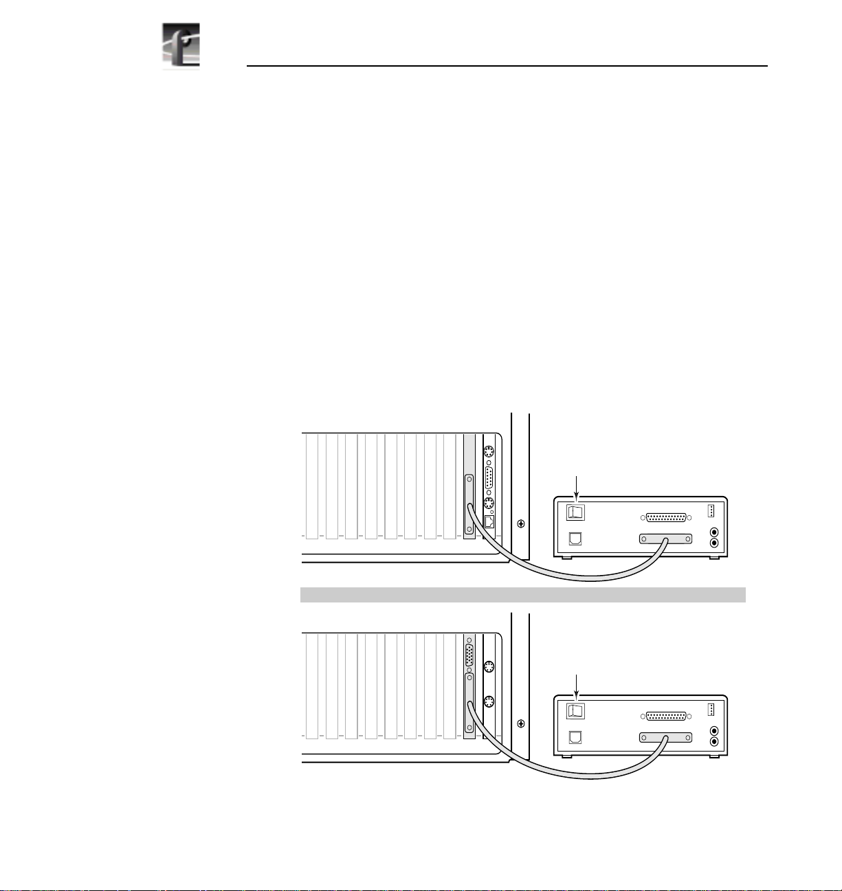
Connecting the CD-ROM Drive
To connect the CD-ROM drive:
1. Shut down your Windows NT session and power off the Profile system.
2. Connect one end of the parallel cable to the CD-ROM drive’s
connector and the other end to the parallel port on the Profile system as shown
in Figure 1.
3. Connect powerto the CD-ROM driveusing the universal powersupply and one
of the four power supply cables provided with the kit.
4. Turn on the CD-ROM drive power switch and power up the Profile system.
TO COMPUTER
J10
J9
J8
J6J7
J4 J3 J2
J5
J1
Power
Switch
TO PRINTER
TO COMPUTER
DC PWR IN
OR
J9
J10
J8
Figure 1. CD-ROM drive cabling for the PDR200, PDR300, and PDR400
J6J7
J4 J3 J2
J5
J1
Power
Switch
TO PRINTER
TO COMPUTER
DC PWR IN
AUDIO
AUDIO
9897-13
18 CD-ROM Instructions
Page 19

Installing the CD-ROM Driver In Windows NT 4.0
Installing the CD-ROM Driver In Windows NT 4.0
To install the driver:
1. Power up the Profile system and logon as administrator using these steps:
a. Hold the
profile. Be sure to hold down the shift key until the logon dialog box
appears.
b. Logon as administrator. The factory default administrator password ona
Profile system is triton.
2. Open the Control Panel by choosing
3. Double-click
4. Choose the
5. Choose
in the Profile system’s floppy drive.
6. Ensure that A:\ appears in the path text box, then click
7. Confirm that theF.I.T. Parallel-Port Trans-Series NT Driveris selected inthe SCSI
Adapter
8. When prompted, change the path to A:\, then click Continue.
Shift key down during start-up to prevent auto-logon as user
Start | Settings | Control Panel.
SCSI Adapters.
Drivers tab and the click then Add button.
Have Disk in the resulting dialog box, then insert theNT Driver Diskette
OK.
list, then click OK.
9. Select Yes to restart the system and logon again as administrator.
NOTE: The message, “At least one service or driver failed during
start-up” displayed during start-up, may indicate a parallel port
problem. Refer to “PDR200, PDR300 and PDR400
Troubleshooting” on page 21.
10. Choose
Start | Programs | Windows NT Explorer and verify that the CD-ROM
drive is listed as a drive. If the CD-ROM drive doesn’t appear, refer to
“PDR200, PDR300 and PDR400 Troubleshooting” on page 21 to help find the
cause.
If the CD-ROM drive does appear, you have successfully installed the
CD-ROM drive for use with Windows NT 4.0 on your Profile system.
NOTE: The CD-ROM drive is not intended to be a permanent part of
the Profile system. Remove the CD-ROM drive when it is no longer
needed using the instructions in “Removing the CD-ROMDrive” on
page 20.
CD-ROM Instructions 19
Page 20

PDR200, PDR300, and PDR400 Installation
Removing the CD-ROM Drive
When you have finished using the CD-ROM drive you should remove it from the
system. Todo this,you must first remove the CD-ROM driver from Windows NT
and then disconnect the CD-ROM drive from the Profile system.
To remove the CD-ROM driver:
1. Power up the Profile system and logon as administrator using the following
steps:
a. Hold the
Shift key down during start-up to prevent auto-logon as user
profile. Be sure to hold down the shift key until the logon dialog box
appears.
b. Logon as administrator. The factory default administrator password ona
Profile system is triton.
2. Open Control Panel by choosing
3. Double-click
SCSI Adapters, then choose the Drivers Tab.
Start | Settings | Control Panel.
4. Select F.I.T. Parallel-Port Trans-Series NT Driver in the list.
5. Click the
6. Click
Remove button.
Yes, then OK.
7. Shut down Windows NT and power down the Profile system and CD-ROM
drive.
8. Disconnect the CD-ROM drive from the system.
9. Power up the Profile system and logon as administrator or as profile.
Logging on as profile will enable the auto-logon feature the next time the
Profile system boots. The factory default passwordfor the profileaccount is
profile.
20 CD-ROM Instructions
Page 21

PDR200, PDR300 and PDR400 Troubleshooting
PDR200, PDR300 and PDR400 Troubleshooting
If, after installing the CD-ROMdrive, Windows NT doesn’tindicate that the drive
is present or the message “At least one service or driver failed during start-up” is
displayed during start-up, try the following simple steps.
1. Check that the parallel cable is securely connected to both the CD-ROM drive
and the Profile system.
2. Check that the CD-ROM drive has power applied.
If neither of these solves the problem, use the following sections to find another
solution.
NOTE: You must logon as Administrator to perform the procedures
that follow. To logon as administrator see step 1 of “Installing the
CD-ROM Driver In Windows NT 4.0” on page 19.
Checking the Windows NT CD-ROM Device Status
To check the Windows NT Cdrom device status:
1. Start
2. Scroll down in the list to
3. Shutdown and restart Windows NT.
Ifthis procedure did notcorrect the problem, theProfile system’sparallel portmay
not be enabled. The following procedure describes how to check this.
Control Panel and select Devices.
Cdrom and verify that start-up is set to System.Ifitis
not set correctly, perform the following:
a. Select
b. Select the
c. Click
Cdrom, then click the Start-up button.
System option.
OK, then Close.
CD-ROM Instructions 21
Page 22

PDR200, PDR300 and PDR400 Troubleshooting
Checking the Parallel Port Status
To determine if the parallel port is enabled:
1. Chose
2. Click the
3. Click the
4. Verify that the parallel port (
5. If these addresses do not appear in the list, you must verify the parallel port
configuration using one of two procedures depending what hardware version
you have installed. Refer to Table 1 to determine which procedure you should
follow to verify the parallel port configuration.
Table 1. Verifying the parallel port configuration
Rear Panel View Procedure To Follow Page
Start | Programs | Administrative Tools | Windows NT Diagnostics.
Resources tab.
I/O Port button.
Parport) addresses of 0378 - 037A are present.
Number
J4 J3 J2
J5
Parallel
Port only
J4 J3 J2
J5
S-VGA
Port
Parallel
Port
J1
J1
“Running Load CMOS to Configure
the Parallel Port”
“Setting VGA-I/O Board Switches to
Configure the Parallel Port”
23
23
22 CD-ROM Instructions
Page 23

Running Load CMOS to Configure the Parallel Port
Running Load CMOS to Configure the Parallel Port
Use this procedure to configure the parallel port when the parallel port addresses
do not appear as they should in the “Checking the Parallel Port Status” procedure
on page 22. In this version of hardware, the parallel port is configured by running
a batch file called Load CMOS.
To run Load CMOS to enable the parallel port:
1. Chose
2. Shut down and restart Windows NT. Logon on as administrator.
3. Choose
Start | Programs | PDR Debug Tools| Load CMOS.
Start | Programs | Windows NT Explorer and verify that the CD-ROM
drive is listed as a drive.
Setting VGA-I/OBoard Switches toConfigure the ParallelPort
Use this procedure to configure the parallel port when the parallel port addresses
do not appear as they should in the “Checking the Parallel Port Status” procedure
on page 22.
In this version of hardware, the parallel port circuitry is located on the system
VGA-I/O board. The parallel port is configured by setting the configuration
switches on the VGA-I/O board. This procedure provides instructions for
removing the VGA-I/O board and checking the parallel port configuration
switches.
To check the VGA-I/O board switches:
1. Confirm that the Profile system power is switched off and the power cord is
removed.
2. Power down the CD-ROM drive and disconnect it from the Profile system.
3. Remove the top covers from the Profile system.
NOTE: In someunits the parallelportconfiguration switches maybe
visible without removing the VGA-I/O board from the unit. If you
have access to the switches without removing the VGA-I/Oboard, go
to step 7 and check the switch positions.
CD-ROM Instructions 23
Page 24

PDR200, PDR300 and PDR400 Troubleshooting
4. Remove the circuit board retainer as shown in Figure 2.
5. The VGA-I/O board is located in slot 2. Remove the circuit board mounting
screw asshown in Figure 3.If the VGA monitorcable is connected to the board
disconnect it now.
24 CD-ROM Instructions
9897-7
Figure 2. Removing the circuit board retainer
Page 25

Setting VGA-I/O Board Switches to Configure the Parallel Port
9897-24
Figure 3. Location of circuit board mounting screw
NOTE: See “General Installation Instructions” on page 17 for
proper circuit board handling warnings.
6. Carefully grasp the board and lift upward to free the circuit board from the
motherboard connector. In some cases,it may be necessaryto remove the board
in the adjacent slot J3 before removing the VGA-I/O board.
CD-ROM Instructions 25
Page 26

PDR200, PDR300 and PDR400 Troubleshooting
7. Set the switches on yourVGA-I/O board as shownin Figure 4 for the CEX595
or Figure 5 for the CEX585.
SW1 SW2
123456
123456
OPEN
123456
OPEN
123456
OPEN
CEX595
OPEN
9897-9
Figure 4. CEX595 VGA-I/O board switch settings to enable parallel port
26 CD-ROM Instructions
Page 27

Setting VGA-I/O Board Switches to Configure the Parallel Port
SW1 SW2
123456
123456
OPEN
OPEN
CEX585
123456
123456
OPEN
OPEN
9897-1
Figure 5. CEX585 VGA-I/O board switch settings to enable parallel port
8. Reinstall the VGA-I/O board by aligning it with the connectors on the
motherboard andthen pressing down firmly untilthe board is seated. Theboard
is properly seated when the top of the rear mounting bracket is resting on the
rear cabinet wall shelf. Reinstall the board mounting screw.
CD-ROM Instructions 27
Page 28

PDR200, PDR300 and PDR400 Troubleshooting
9. Reinstall the circuit board retainer.
10. Reinstall the top covers; install the rear cover first, then the front cover.
11. Reinstall the Video File Server in the rack and reconnect all cables previously
removed.
12. Reconnect the CD-ROM drive to the Profile system parallel port and then,
power up the CD-ROM drive.
13. Power up the Profile system and logon on as administrator.
14. Choose
Start | Programs | Windows NT Explorer and verify that the CD-ROM
drive is listed as a drive.
28 CD-ROM Instructions
Page 29

PDR100 Installation
PDR100 Installation
This section contains procedures for installing the CD-ROM drive on PDR100
systems. Procedures are included for all PDR100 System CPU board hardware
versions. Which installation procedure you follow is determined by your System
CPU board hardware version.
Procedures in this section will help you:
- Determine your System CPU hardware version.
- Determine your starting point in the procedures depending on your
System CPU board hardware version.
- Install and test the CD-ROM drive.
Use following section to determine your System CPU board hardware version.
Determining the System CPU Board Hardware Version
You can determine the hardware version of your PDR100 by looking at the
PDR100 rear panel and observing the text displayed by the System CPU board
BIOS at power up, and then referring to Table 2.
To determine System CPU board hardware version:
1. Power On the SVGA Monitor connected to the PDR100.
2. Power On the PDR100, and then press the
first screen of text appears.
3. Compare your BIOS boot screen text and PDR100 rear panel to thoseshown in
Table 2 to determine your starting procedure.
Pause key on keyboard when the
CD-ROM Instructions 29
Page 30

PDR100 Installation
Table 2. Procedure selection table
Rear Panel View BIOS Boot Screen Text
DTI Advanced BIOS Software Version 1.X
Copyright (C)1993-1994 Diversified Technology,Inc
All Rights Reserved (C) 1984-90, Award Software Inc
Power On Self Test Results
ESP2002 - Tektronix Release 1.X
DTI Advanced BIOS Software Version 1.X
Copyright (C)1993-1994 Diversified Technology,Inc
All Rights Reserved (C) 1984-90, Award Software Inc
Power On Self Test Results
ESP2002 - Tektronix Release 1.X
Parallel
Port
J2
J2
J1
J1
a
Hardware
Description
486 System CPU
board
.
Ultimate VGA
board
No parallel port
installed.
486 System CPU
board
.
Ultimate VGA
board
System CPU
board parallel
port installed.
(Connector may
be located in
another slot)
Starting Procedure
and Page Number
“Installing the Parallel
Port” on page 32.
“Connecting the
CD-ROM Drive to the
PDR100” on page 42.
DTI Advanced BIOS Software Version 1.X
Copyright (C)1993-1994 Diversified Technology,Inc
J2
J1
All Rights Reserved (C) 1984-90, Award Software Inc
30 CD-ROM Instructions
Power On Self Test Results
ESP2002 - Tektronix Release 1.X
486 System CPU
board
.
CEX585 or
CEX 595
VGA-I/Ob board
No parallel port
installed.
“Installing the Parallel
Port” on page 32.
Page 31

Determining the System CPU Board Hardware Version
Table 2.
Rear Panel View BIOS Boot Screen Text
J2
J1
Parallel
Port
J2
J1
Procedure selection table (Continued)
DTI Advanced BIOS Software Version 1.X
Copyright (C)1993-1994 Diversified Technology,Inc
All Rights Reserved (C) 1984-90, Award Software Inc
Power On Self Test Results
ESP2002 - Tektronix Release 1.X
PhoenixBIOS Version 4.x
Copyright 1985-1995 Phoenix Technologies Ltd.
Copyright 1996, Diversified Technology, Inc.
All Rights Reserved.
ESP3520B Rls. 1.X
a
Hardware
Description
486 System CPU
board
.
CEX585 or
CEX 595
VGA-I/Ob board
System CPU
board parallel
port installed.
(Connector may
be located in
another slot)
Pentium System
CPU board
CEX585 or
CEX 595
VGA-I/O board
with parallel port
enabled.
Starting Procedure
and Page Number
“Connecting the
CD-ROM Drive to the
PDR100” on page 42.
“Connecting the
CD-ROM Drive to the
PDR100” on page 42.
Press <F2> to enter SETUP
J2
J1
PhoenixBIOS Version 4.x
Copyright 1985-1995 Phoenix Technologies Ltd.
Copyright 1996, Diversified Technology, Inc.
All Rights Reserved.
ESP3521 Rls. 1.X
Press <F2> to enter SETUP
Pentium System
CPU board
CEX585 or
CEX 595
VGA-I/O board
with parallel port
enabled.
“Connecting the
CD-ROM Drive to the
PDR100” on page 42.
a. Press the keyboard Pause key to pause BIOS during bootup; press any other key to continue.
b. The VGA-I/O board parallel port (in slot J2) is disabled when used with the 486 System CPU board.
CD-ROM Instructions 31
Page 32

PDR100 Installation
Installing the Parallel Port
This procedure describes howto install the parallel port on PDR 100 systems with
the 486 System CPU board. The parallel port will provide a 25-pin D-connector
for attaching the CD-ROM drive to the PDR100.
This procedure has three parts:
- Removing the Top Covers
- Verifying Switch Settings On the VGA-I/O Board (if installed)
- Installing the Parallel Port L-bracket
- Enabling the System CPU Board Parallel Port
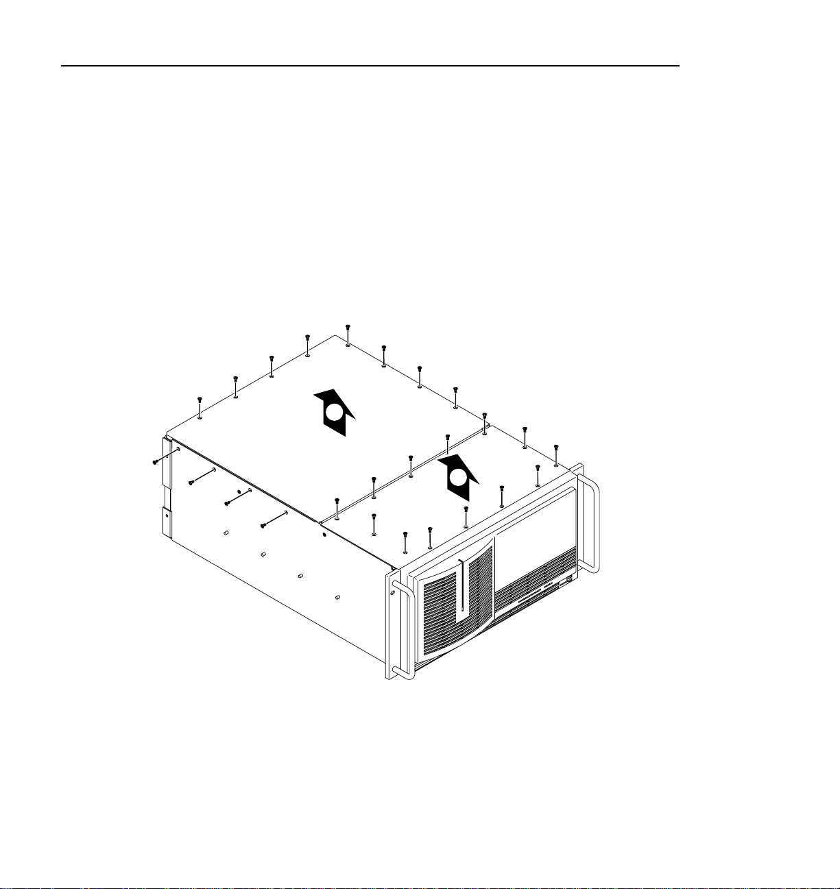
Removing the Top Covers
To remove both chassis covers:
1. Confirm that the PDR100 power is switched off and the power cord is
removed.
2. Use the Torx tool with the T10 tip to remove the top screws from the front
chassis cover (➊ in Figure 6).
NOTE: Take carenot to losethese chassisscrews. Theyare requiredto meet
the EMI specifications for the PDR100.
3. Use the Torx tool with the T10 tip to remove the rear chassis cover
(➋in Figure 6) which covers the circuit boards.
32 CD-ROM Instructions
Page 33

Installing the Parallel Port
2
1
9496-1
Figure 6. Removing the top covers
CD-ROM Instructions 33
Page 34

PDR100 Installation
Verifying Switch Settings On the VGA-I/O Board (if installed)
Some PDR100 units have the VGA-I/O board installed which includes a parallel
port. Ifthis board is installedwith the 486 SystemCPU board, you must makesure
the parallel port on the VGA-I/O board is disabled by verifying the configuration
switch settings. (If you need to determine your System CPU board hardware
version, refer to “Determining the System CPU Board Hardware Version” on
page 29.)
To determine if a VGA-I/O Board is installed and to verify switch settings:
1. Compare yourPDR100 to Figure 7,which showsVGA boards withand without
a parallel port. Then do one of the following:
a. If you have a VGA board without a parallel port, proceed with “Installing
b. If you have a VGA I/O board with a parallel port you must verify the
the Parallel Port L-bracket” on page 39.
switch settings by continuing with the next step in this procedure.
34 CD-ROM Instructions
Without
Parallel
Port
Figure 7. PDR100 VGA board with and without a parallel port
Parallel
With
Port
9897-2
Page 35

Installing the Parallel Port
2. Verify that your VGA-I/O board switch settings match Figure 8 for the
CEX595 or Figure 9 for the CEX585, then proceed to “Installing the Parallel
Port L-bracket” on page 39.
NOTE: In some cases, you may have to remove the VGA-I/O board
to gain access to configuration switches. Continue with step 3 on
page 37 of this procedure to remove the VGA-I/O board.
SW1 SW2
123456
123456
OPEN
123456
OPEN
123456
OPEN
CEX595
OPEN
9897-12
Figure8.CEX595VGA-I/Oboardswitchsettingswhenusedwiththe486SystemCPU board
CD-ROM Instructions 35
Page 36

PDR100 Installation
123456
OPEN
123456
OPEN
CEX585
123456
123456
OPEN
OPEN
9897-8
Figure9.CEX585VGA-I/Oboardswitchsettingswhenusedwiththe486SystemCPU board
36 CD-ROM Instructions
Page 37

Installing the Parallel Port
3. To remove the VGA-I/O board to gain access the configuration switches:
a. Remove the circuit board retainer as shown in Figure 10.
9897-7
Figure 10. Removing the circuit board retainer
b. The VGA-I/O board is located in slot J2. Remove the circuit board
mounting screw as shown in Figure 11.
CD-ROM Instructions 37
Page 38

PDR100 Installation
9897-24
c. If the VGA monitor cable is connected to the board, disconnect it now.
NOTE: See “General Installation Instructions” on page 17 for
proper circuit board handling warnings.
d. Carefully grasp theboard and lift upwardto free the circuitboard from the
motherboardconnectors. In somecases, itmay be necessaryto remove the
board in the adjacent slot J3 before removing the VGA-I/O board.
e. Verifyyour VGA-I/O boardswitch settings matchFigure 8on page35 for
the CEX595 board or Figure 9 on page 36 for the CEX585 board.
f. Reinstall the VGA-I/O board by aligning it with the connectors on the
motherboard and then pressing down firmly until the boardis seated. The
board is properly seated when the top of the rear mounting bracket is
resting on the rear cabinet wall shelf.
g. Reinstall the circuit board mounting screw and then proceed to the next
section “Installing the Parallel Port L-bracket”.
38 CD-ROM Instructions
Figure 11. Location of circuit board mounting screw
Page 39

Installing the Parallel Port
Installing the Parallel Port L-bracket
To install the parallel port L-bracket:
1. Remove the blank L-bracket from any empty rear panel slot.
2. Install the parallel port L-bracket supplied with the CD-ROM drive kit.
See
➊ in Figure 12.
1
2
2
Figure 12. Installing the parallel port L-bracket and cabling
3. Connect the CPU parallel port cable between the processor board and the
parallel port L-bracket. See
➋ in Figure 12.
CD-ROM Instructions 39
9897-4
Page 40

PDR100 Installation
4. Apply the parallel port identification label to the rear panel of the PDR100 as
follows:
a. Locate theParallel Port/System CPU label on thelabel sheet shipped with
b. Using a pair of scissors, trim off the System CPU half of the label.
c. Place the ParallelPort label on the board identification strip in frontof the
5. Reinstall the circuit board retainer (refer to Figure 10 on page 37).
6. Reinstall the top covers; install the rear cover first, then the front cover.
7. If the PDR100 was removed from the rack, you may now reinstall it.
Enabling the System CPU Board Parallel Port
PDR100 systems with the 486 System CPU board were shipped from the factory
with theparallel port disabled. Youmust run a batchfile to enable the parallelport.
If you are using Profile system software 2.0 or higher, the batch file is already on
your the PDR100 system hard drive. If you are using Profile system software
1.4.X or lower, the batch fileis located on the NT DriverDiskette shipped with the
CD-ROM drive.
this CD-ROM drive.
newly installed parallel port.
To enable the 486 System CPU board parallel port:
1. Power up the Profile system and logon as administrator using the following
steps:
a. Hold the
profile. Be sure to hold down the shift key until the logon dialog box
appears.
b. Logon as administrator. The factory default administrator password ona
Profile system is triton.
2. Determine the version of Profile system software you are using by following
these instructions:
a. Start the
group (in Windows NT 3.51) or folder (in Windows NT 4.0).
b. From the VdrPanel menu bar select
c. Record the version number shown as
d. Quit VdrPanel and any other Profile applications.
40 CD-ROM Instructions
Shift key down during start-up to prevent auto-logon as user
VdrPanel application located in the Profile Applications program
Help | About VdrPanel.
Product Version.
Page 41

Installing the Parallel Port
3. Locate your Profile system software version in Table 3, then follow the
instructions listed for your software version.
Table 3. Procedures to enable parallel port settings in CMOS
IF your Profile software version is THEN perform these instructions
2.0 or higher If Windows NT 3.51:
1. Open PDR Debug Tools program group.
2. Double-click
3. Shut down and restart Windows NT, then logon as
Administrator.
If Windows NT 4.0:
1. Select
CMOS.
2. Shut down and restart Windows NT and then logon as
Administrator.
LOAD CMOS icon.
Start | Programs | PDR Debug Tools | Load
1.4.15 or higher, but lower than 2.0 1.Place CD-ROM driveNT DriverDiskette in the floppy
1.4.14 or lower 1. Place CD-ROMdrive NT Driver Diskette in the floppy
disk drive.
2. If Windows NT 3.51, chose
Manager
If Windows NT 4.0, select
3. Type A:\newcmos\loadcmos, then press Enter.
4. Shutdown and restart Windows NT, then logon as
Administrator.
disk drive.
2. If Windows NT 3.51, chose
Manager
If Windows NT 4.0, select
3. Type A:\oldcmos\loadcmos, then press Enter.
4. Shutdown and restart Windows NT and then, logon as
Administrator.
File menu.
File menu.
Run in the Program
Start | Run
Run in the Program
Start | Run
Now that the PDR100 parallel port is installed and enabled, you are ready to
connect theCD-ROM drive.The next section, “Connectingthe CD-ROM Driveto
the PDR100” on page 42, describes how to do this.
CD-ROM Instructions 41
Page 42

PDR100 Installation
Connecting the CD-ROM Drive to the PDR100
This section provides instructions for connecting the CD-ROM drive to your
PDR100 system and local power source.
To connect the CD-ROM drive:
1. Shut down your Windows NT session and power off the PDR100.
2. Connect one end of the parallel cable to the CD-ROM drive’s
connector and the other endto the parallel port on the PDR100. Table 4 shows
examples of CD-ROM drive parallel port connections for different PDR100
hardware versions.
3. Connect powerto the CD-ROM driveusing the universal powersupply and one
of the four power supply cables provided with the kit.
4. Turn on the CD-ROM drive power switch and power up the PDR100.
Now that your CD-ROMdrive is connected to your PDR100, you must installthe
Windows NT device driver. The next section describes how to do this.
TO COMPUTER
42 CD-ROM Instructions
Page 43

Connecting the CD-ROM Drive to the PDR100
Table 4. Connecting the CD-ROM drive to the PDR100 parallel port
Hardware Versions
486 System CPU board
Ultimate VGA board
The System CPU board
parallel port may not be
in slot J4. Check rear
panel labels.
486 System CPU board
CEX585 or CEX595
VGA-I/Ob board
The System CPU board
parallel port may not be
in slot J4. Check rear
panel labels.
a
CD-ROM Drive Connections To the Parallel Port
J4 J3 J2
J5
J1
Power
Switch
DC PWR IN
J3 J2
J4
J5
J1
Power
Switch
DC PWR IN
TO PRINTER
TO COMPUTER
AUDIO
9897-21
TO PRINTER
TO COMPUTER
AUDIO
9897-22
Pentium System CPU Bd.
CEX585 or CEX595
J4 J3 J2
J5
J1
VGA-I/O board with
parallel port enabled.
Power
Switch
TO PRINTER
TO COMPUTER
DC PWR IN
AUDIO
9897-23
a. Refer to “Determining the System CPU Board Hardware Version” on page 29 to verify your
hardware version.
b. The VGA-I/O board parallel port (in slot J2) is disabled when used with the 486 System CPU board.
CD-ROM Instructions 43
Page 44

PDR100 Installation
Installing the Windows NT CD-ROM Driver
This section contains instructions for installing the CD-ROM device driver.
Procedures are included for Windows NT 3.51 and Windows NT 4.0. Locate the
NT Driver Diskette shipped withCD-ROM driveand thenuse one of thefollowing
procedures to install the CD-ROM driver.
NOTE: No Windows NT 3.50 compatible driver is available for this
CD-ROM drive. However, the CD-ROM drive may be used to
upgrade Windows NT 3.50. See “Upgrading Windows NT 3.50” on
page 15 for more information.
Installing the CD-ROM Driver in Windows NT 3.51
Installing the CD-ROM driverin Windows NT 3.51 on the PDR100 also involves
enabling the Scsicdrm device. The procedures that followdescribe how to do this.
To enable the Scsicdrm device and install the CD-ROM driver:
1. Power up the PDR100 and logon as administrator using these steps:
a. Hold the
profile. Be sure to hold down the shift key until the logon dialog box
appears.
b. Logon as administrator. The factory default administrator password ona
PDR100 is triton.
2. Open the
3. Scroll down inthe list to
set correctly:
a. Highlight
b. Select the
c. Click
4. In the Main Program Group, start the Windows NT Setup application.
5. In
Windows NT Setup, choose Options | Add/Remove SCSI Adapters.
6. Click Add.
7. When the Setup Message appears, read it and then click
44 CD-ROM Instructions
Shift key down during start-up to prevent auto-logon as user
Control Panel, then double-click Devices.
Scsicdrm and verify thatit is set to System.Ifitisnot
Scsicdrm and then click Start-up.
System option.
OK and then Close.
OK.
Page 45

Installing the Windows NT CD-ROM Driver
8. Select Other in the drop down list of drivers.
9. When the Insert Disk dialog box appears, insert the NT Driver Diskette in the
PDR100 floppy drive and then click
10. Select the F.I.T. Parallel-Port Trans-Series NT Driver, then click OK.
11. When the Select SCSI Adapter Option dialog box appears, verify that F.I.T. is
selected and then click
Install.
12. When Windows NT Setup dialog box appears verify path is A:\, then chose
Continue.
13. Chose Close.
14. Remove the NT Driver Diskette and then shutdown and restart Windows NT.
Logon as Administrator.
NOTE: The message, “At least one service or driver failed during
start-up” displayed during start-up, may indicate a parallel port
problem. Refer to “PDR100 Troubleshooting” on page 49.
OK.
15. Open
File Manager and verify that theCD-ROM drive islisted asa drive.If the
CD-ROM drive doesn’t appear, refer to “PDR100 Troubleshooting” on
page 49 to help find the cause.
If the CD-ROM drive does appear, you have successfully installed the
CD-ROM drive for use with Windows NT 3.51 on your PDR100.
NOTE: The CD-ROM drive is not intended to be a permanent part of
the Profile system. Remove the CD-ROM drive when it is no longer
needed using the instructions in “Removing the CD-ROMDrive” on
page 47.
Installing the CD-ROM Driver in Windows NT 4.0
To install the CD-ROM driver in Windows NT 4.0:
1. Power up the PDR100 and logon as administrator using these steps:
a. Hold the
profile. Be sure to hold down the shift key until the logon dialog box
appears.
b. Logon as administrator. The factory default administrator password ona
PDR100 is triton.
Shift key down during start-up to prevent auto-logon as user
CD-ROM Instructions 45
Page 46

PDR100 Installation
2. Open Control Panel by choosing Start | Settings | Control Panel.
3. Double-click
4. Choose the
5. Choose
Diskette in the PDR100 floppy drive.
6. Ensure that A:\ appears in the path text box, then click
7. Confirm that theF.I.T. Parallel-Port Trans-Series NT Driveris selected inthe SCSI
Adapter
8. When prompted, change the path to A:\, then click Continue.
9. Select Yes to restart the system and logon again as administrator.
NOTE: The message, “At least one service or driver failed during
start-up” displayed during start-up, may indicate a parallel port
problem. Refer to “PDR100 Troubleshooting” on page 49.
SCSI Adapters.
Drivers tab and then click the Add button.
Have Disk in the resulting dialog box and then insert the NT Driver
OK.
list, then click OK.
10. Choose
Start | Programs | Windows NT Explorer and verify that the CD-ROM
drive is listed as a drive. If the CD-ROM drive doesn’t appear, refer to
“PDR100 Troubleshooting” on page 49 to help find the cause.
If the CD-ROM drive does appear, you have successfully installed the
CD-ROM drive for use with Windows NT 4.0 on your PDR100.
NOTE: The CD-ROM drive is not intended to be a permanent part of
the Profile system. Remove the CD-ROM drive when it is no longer
needed using the instructions in “Removing the CD-ROMDrive” on
page 47.
46 CD-ROM Instructions
Page 47

Removing the CD-ROM Drive
When you have finished using the CD-ROM drive, you should remove it from the
PDR100. To do this, you must first remove the CD-ROM driver from
Windows NT, then disconnect the CD-ROM drive from the PDR100. Procedures
are included here for Windows NT 3.51 and 4.0. Use one of the following
procedures to remove the CD-ROM drive.
Removing the CD-ROM Driver From Windows NT 3.51
To remove the CD-ROM driver from Windows NT 3.51.
1. Power up the PDR100 and logon as administrator using the following steps:
Removing the CD-ROM Drive
a. Hold the
Shift key down during start-up to prevent auto-logon as user
profile. Be sure to hold down the shift key until the logon dialog box
appears.
b. Logon as administrator. The factory default administrator password ona
PDR100 is triton.
2. In the
3. In
Main Program Group, start the Windows NT Setup application.
Windows NT Setup, choose Options | Add/Remove SCSI Adapters.
4. Highlight F.I.T. Parallel-Port Trans-Series NT Driver in the list.
5. Click
6. When the Setup Message appears, read it, then click
7. Read the second Setup Message, then click
8. Click
Remove.
OK.
OK.
Close.
9. Shut down Windows NT, power down the PDR100 and CD-ROM drive.
10. Disconnect the CD-ROM drive from the system.
11. Power up the PDR100 and logon as administrator or as profile.
Logging on as profile will enable the auto-logon feature the next time the
PDR100 boots. The factory default password for the profile account is
profile.
CD-ROM Instructions 47
Page 48

PDR100 Installation
Removing the CD-ROM Driver From Windows NT 4.0
To remove the CD-ROM driver from Windows NT 4.0.
1. Power up the PDR100 and logon as administrator using the following steps:
a. Hold the
Shift key down during start-up to prevent auto-logon as user
profile. Be sure to hold down the shift key until the logon dialog box
appears.
b. Logon as administrator. The factory default administrator password ona
PDR100 is triton.
2. Open Control Panel by choosing
3. Double-click
SCSI Adapters, then choose the Drivers Tab.
Start | Settings | Control Panel.
4. Select F.I.T. Parallel-Port Trans-Series NT Driver in the list.
5. Click the
6. Click
Remove button.
Yes, then OK.
7. Shut down Windows NT, and power down the PDR100 and CD-ROM drive.
8. Disconnect the CD-ROM drive from the system.
9. Power up the PDR100 and logon as administrator or as profile.
Logging on as profile will enable the auto-logon feature the next time the
PDR100 boots. The factory default password for the profile account is
profile.
48 CD-ROM Instructions
Page 49

PDR100 Troubleshooting
If, after installing the CD-ROM drive, Windows NT does not indicate that the
drive is present or the message, “At least one service or driver failed during
start-up”, is displayed during start-up, try the following simple steps.
1. Check that the parallel cable is securely connected to both the CD-ROM drive
and the PDR100.
2. Check that the CD-ROM drive has power applied.
If neither of these solves the problem, use the following sections to find another
solution.
NOTE: The procedures that follow require you to be logged on as
Administrator. Refer to “Installing the Windows NT CD-ROM
Driver” on page 44 for instructions on logging on as Administrator.
Checking the Windows NT Device Status
These procedures provide instructions for checking that the Windows NT
CD-ROM device status is properly set. Procedures are included for Windows NT
3.51 and 4.0. Use one of the following procedures to check the CD-ROM device
status.
PDR100 Troubleshooting
Checking the CD-ROM Device Status In Windows NT 3.51
To check the CD-ROM device status:
1. Open the
2. Scroll down inthe list to
set correctly:
a. Highlight
b. Select the
c. Click
3. Shutdown and restart Windows NT, then logon as administrator.
4. Open
If this procedure did not correct the problem, the PDR100 parallel portmay not be
enabled. Continue with “Checking the Parallel Port Status” on page 50.
Control Panel, then double-click Devices.
Scsicdrm and verify thatit is set to System.Ifitisnot
Scsicdrm, then click the Start-up button.
System option.
OK and then Close.
File Manager and verify that the CD-ROM drive is listed as a drive.
CD-ROM Instructions 49
Page 50

PDR100 Troubleshooting
Checking the CD-ROM Device Status In Windows NT 4.0
To check the CD-ROM device status:
1. Start
2. Double-click on the
3. Scroll down in the list to
Control Panel by selecting Start | Settings | Control Panel.
Devices icon.
Cdrom and verify that start-up is set to System.Ifitis
not set correctly, perform the following:
a. Select
b. Select the
c. Click
Cdrom, then click the Start-up button.
System option.
OK, then Close.
4. Shutdown and restart Windows NT.
If this procedure did not correct the problem, the PDR100 parallel portmay not be
enabled. Continue with “Checking the Parallel Port Status”.
Checking the Parallel Port Status
Use the following procedures to determine if the parallel port is enabled.
Procedures are included for Windows NT 3.51 and 4.0. Use one of the following
procedures to check the parallel port status.
Checking the Parallel Port Status In Windows NT 3.51
To check the parallel port status:
1. Open the
Administrative Tools group.
2. Double click the
3. Click
IRQ/Port Status button.
4. Scroll through the
0x378 0x3 \Device\Parallel\Port0
If the parallel port address does not appear in the list, you must verify the
parallel port configuration using“Verifying the Parallel Port Configuration”
on page 52.
50 CD-ROM Instructions
Windows NT Diagnostics icon.
Ports list and verify the parallel port is listed as follows:
Page 51

Checking the Parallel Port Status
Checking the Parallel Port Status In Windows NT 4.0
To check the parallel port status:
1. Chose
2. Click on the
3. Click the
4. Verify that the parallel port (
Start | Programs | Administrative Tools | Windows NT Diagnostics.
Resources tab.
I/O Port button.
Parport) addresses of 0378 - 037A are present.
If the parallel port address does not appear in the list, you must verify the
parallel port configuration using“Verifying the Parallel Port Configuration”
on page 52.
CD-ROM Instructions 51
Page 52

PDR100 Troubleshooting
Verifying the Parallel Port Configuration
If the parallel port addresses do not appear in the list of resources in the previous
procedure, “Checking the Parallel Port Status”, you must verify the parallel port
configuration using one of three procedures depending on what hardware version
you have installed. Refer to Table 5 and follow the instructionsfor yourhardware
version.
Table 5. Instructions for verifying parallel port configuration
Hardware Description
486 System CPU board
Ultimate VGA board
System CPU board parallel
port installed.
486 System CPU board
CEX585 or CEX 595
VGA I/O board with parallel
port
disabled.
System CPU board parallel
port installed.
Pentium System CPU board
CEX585 or CEX 595
VGA I/O board with parallel
port
enabled.
a. To verify your hardware version, refer to “Determining the System CPU Board Hardware
Version” on page 29.
a
Procedure To Follow
Check that you have enabled the parallel port on the System
CPU board. Follow the procedures in “Enabling the System
CPU Board Parallel Port” on page 40.
1. Check that you have disabled the parallel port on the
VGA-I/O board. Follow the procedures in “Verifying Switch
Settings On the VGA-I/O Board (if installed)” on page 34.
2. Check that you have enabled the parallel port on the System
CPU board. Follow the procedures in “Enabling the System
CPU Board Parallel Port” on page 40.
Checkfor correct switchsettings on theVGA-I/O board. Follow
the procedures in “Verifying theVGA-I/O Board Configuration
Switches” on page 52.
Verifying the VGA-I/O Board Configuration Switches
This procedure provides instructions for verifying the parallel port configuration
switches onVGA-I/O boards usedin PDR100 systems with PentiumSystem CPU
boards.
To check the VGA-I/O board switches:
1. Confirm thatthe PDR100 power isswitched off andthe power cordis removed.
2. Power down the CD-ROM drive and disconnect it from the PDR100.
52 CD-ROM Instructions
Page 53
Verifying the Parallel Port Configuration
3. Use the Torx tool with the T10 tip to remove the top screws from the front
chassiscover (➊inFigure 13).The front covermust be removed beforethe rear
cover.
NOTE: Take carenot tolose these chassisscrews. Theyare requiredto meet
the EMI specifications for the PDR100.
4. Use the Torx tool with the T10 tip to remove the rear chassis cover
(➋in Figure 13) which covers the circuit boards.
2
1
9496-1
Figure 13. Removing the top covers
CD-ROM Instructions 53
Page 54

PDR100 Troubleshooting
NOTE: In someunits the parallelportconfiguration switches maybe
visible without removing the VGA-I/O board from the unit. If you
have access to the switches without removing the VGA-I/Oboard, go
to step 8 on page 55 and check the switch positions.
5. Remove the circuit board retainer as shown in Figure 14.
54 CD-ROM Instructions
9897-7
Figure 14. Removing the circuit board retainer
Page 55

Verifying the Parallel Port Configuration
6. The VGA-I/O board is located in slot J2. Remove the circuit board mounting
screw as shown in Figure 15. If the VGA monitor cable is connected to the
board disconnect it now.
9897-24
Figure 15. Location of circuit board mounting screw
NOTE: See “General Installation Instructions” on page 17 for
proper circuit board handling warnings.
7. Carefully grasp the board and lift upward to free the circuit board from the
motherboard connector. In some cases,it may be necessaryto remove the board
in the adjacent slot J3 before removing the VGA-I/O board.
8. Set theswitches on yourVGA-I/O board as shownin Figure 16 for the CEX595
or Figure 17 for the CEX585.
CD-ROM Instructions 55
Page 56

PDR100 Troubleshooting
123456
SW1 SW2
123456
OPEN
123456
OPEN
123456
OPEN
CEX595
OPEN
9897-9
Figure 16. CEX595 VGA-I/O board switch settings when used with the Pentium System
CPU board
56 CD-ROM Instructions
Page 57

SW1 SW2
123456
Verifying the Parallel Port Configuration
123456
OPEN
123456
OPEN
CEX585
123456
OPEN
OPEN
9897-1
Figure 17. CEX585 VGA-I/O board switch settings when used with the Pentium System
CPU board.
9. Reinstall the VGA-I/O board by aligning it with the connectors on the
motherboard andthen pressing down firmly untilthe board is seated. Theboard
is properly seated when the top of the rear mounting bracket is resting on the
rear cabinet wall shelf. Reinstall the board mounting screw.
10. Reinstall the circuit board retainer.
11. Reinstall the top covers; install the rear cover first, then the front cover.
12. Reinstall the Video File Server in the rack and reconnect all cables previously
removed.
13. Reconnect the CD-ROM drive to the PDR100 parallel port andthen, power up
the CD-ROM drive.
14. Power up the PDR100 and then logon as administrator.
15. Open
File Manager (in Windows NT 3.51) or Explorer (in Windows 4.0) and
verify that the CD-ROM drive is listed as a drive.
CD-ROM Instructions 57
Page 58

PDR100 Troubleshooting
58 CD-ROM Instructions
 Loading...