

Page 1

Prelude
COMPACT ROUTER CONTROL SYSTEM
Instruction Manual
SOFTWARE VERSION 3.0
071838202
MAY 2008
Page 2

Affiliate with the N.V. KEMA in The Netherlands
CERTIFICATE
Certificate Number: 510040.001
The Quality System of:
Grass Valley, Inc.
400 Providence Mine Road
Nevada City, CA 95945
United States
15655 SW Greystone Ct.
Beaverton, OR 97006
United States
10 Presidential Way
3
rd
Floor, Suite 300
Woburn, MA 01801
United States
Nederland B.V.
4800 RP BREDA
The Netherlands
Weiterstadt, Germany
Brunnenweg 9
D-64331 Weiterstadt
Germany
Rennes, France
Rue du Clos Courtel
Cesson-Sevigne, Cedex
France
Technopole Brest Iroise
CS 73808
29238 Brest Cedex 3
France
17 rue du Petit Albi-BP 8244
95801 Cergy Pontoise
Cergy, France
2300 South Decker Lake Blvd.
Salt Lake City, UT 84119
United States
7140 Baymeadows Way
Suite 101
Jacksonville, FL 32256
United States
Including its implementation, meets the requirements of the standard:
ISO 9001:2000
Scope:
The design, manufacture and support of video hardware and software products and
related systems.
This Certificate is valid until: June 14, 2009
This Certificate is valid as of: August 30, 2006
Certified for the first time: June 14, 2000
H. Pierre Sallé
President
KEMA-Registered Quality
The method of operation for quality certification is defined in the KEMA General Terms
And Conditions For Quality And Environmental Management Systems Certifications.
Integral publication of this certificate is allowed.
KEMA-Registered Quality, Inc.
4377 County Line Road
Chalfont, PA 18914
Ph: (215)997-4519
Fax: (215)997-3809
CRT 001 073004
ccredited By:
ANAB
A
Page 3
Prelude
COMPACT ROUTER CONTROL SYSTEM
Instruction Manual
SOFTWARE VERSION 3.0
071838202
MAY 2008
Page 4

Contacting Grass Valley
International
Support Centers
Local Support
Centers
ailable
(av
during normal
business hours)
France
24 x 7
Australia and New Zealand: +6
Middle East: +9
Europe
+800 8080 2020 or +33 1 48 25 20 20
+800 8080 2020 or +33 1 48 25 20 20
Hong Kong, Taiwan, Korea, Macau: +8
Asia
Southeast Asia/Malaysia: +6
China: +8
Belarus, Russia, Tadzikistan, Ukraine,
S. Europe/Italy-Roma: +3
Benelux/Belgium: +3
Germany, Austria, Eastern Europe: +4
61 0660 159 450 Japan: +81 3 5484 6868
71 4 299 64 40 Near East and Africa: +800 8080 2020 or +33 1 48 25 20 20
Copyright © Thomson. All rights reserved.
This product may be covered by one or more U.S. and foreign patents.
Grass Valley Web Site
The www.thomsongrassvalley.com web site offers the following:
Online User Documentation — Current versions of product catalogs, brochures,
data sheets, ordering guides, planning guides, manuals, and release notes
in .pdf format can be downloaded.
FAQ Database — Solutions to problems and troubleshooting efforts can be
found by searching our Frequently Asked Questions (FAQ) database.
United States/Canada
24 x 7
52 2531 3058 Indian Subcontinent: +91 22 24933476
03 7805 3884 Southeast Asia/Singapore: +65 6379 1313
1 1300 721 495 Central/South America: +55 11 5509 3443
Uzbekistan: +7 095 2580924 225 Switzerland: +41 1 487 80 02
9 06 87 20 35 28 -Milan: +39 02 48 41 46 58 S. Europe/Spain: +34 91 512 03 50
2 (0) 2 334 90 30 Benelux/Netherlands: +31 (0) 35 62 38 42 1 N. Europe: +45 45 96 88 70
9 6150 104 444 UK, Ireland, Israel: +44 118 923 0499
+1 800 547 8949 or +1 530 478 4148
Software Downloads — Download software updates, drivers, and patches.
4 Prelude — Instruction Manual
Page 5

Contents
Preface. . . . . . . . . . . . . . . . . . . . . . . . . . . . . . . . . . . . . . . . . . . . . . . . . . . . . . . . . . . . . . . . . . . . . 9
Section 1 — Prelude System Overview . . . . . . . . . . . . . . . . . . . . . . . . . . . . . . . . 11
Section 2 — Installation and Initial Setup . . . . . . . . . . . . . . . . . . . . . . . . . . . . . 15
About This Manual . . . . . . . . . . . . . . . . . . . . . . . . . . . . . . . . . . . . . . . . . . . . . . . . . . . . . 9
Additional Documentation . . . . . . . . . . . . . . . . . . . . . . . . . . . . . . . . . . . . . . . . . . . . 9
Introduction . . . . . . . . . . . . . . . . . . . . . . . . . . . . . . . . . . . . . . . . . . . . . . . . . . . . . . . . . . 11
Prelude 3.0 System Capabilities . . . . . . . . . . . . . . . . . . . . . . . . . . . . . . . . . . . . . . . . . 12
Prelude 3.0 Limitations. . . . . . . . . . . . . . . . . . . . . . . . . . . . . . . . . . . . . . . . . . . . . . . 13
Upgrade Paths . . . . . . . . . . . . . . . . . . . . . . . . . . . . . . . . . . . . . . . . . . . . . . . . . . . . . . . . 14
Introduction . . . . . . . . . . . . . . . . . . . . . . . . . . . . . . . . . . . . . . . . . . . . . . . . . . . . . . . . . . 15
Installation Procedures Overview . . . . . . . . . . . . . . . . . . . . . . . . . . . . . . . . . . . . . . . 15
Initial Shipment . . . . . . . . . . . . . . . . . . . . . . . . . . . . . . . . . . . . . . . . . . . . . . . . . . . . . 15
Back Ordered Shipments or Additional Equipment Purchases. . . . . . . . . . . . . 16
Hardware Installation . . . . . . . . . . . . . . . . . . . . . . . . . . . . . . . . . . . . . . . . . . . . . . . . . 17
Prelude/Concerto System Diagram . . . . . . . . . . . . . . . . . . . . . . . . . . . . . . . . . . . . 17
Concerto Installation Notes . . . . . . . . . . . . . . . . . . . . . . . . . . . . . . . . . . . . . . . . . 17
Prelude/Acappella System . . . . . . . . . . . . . . . . . . . . . . . . . . . . . . . . . . . . . . . . . . . 18
Acappella Installation Notes . . . . . . . . . . . . . . . . . . . . . . . . . . . . . . . . . . . . . . . . 18
Combined Concerto/Acappella Prelude System . . . . . . . . . . . . . . . . . . . . . . . . . 18
Network Requirements . . . . . . . . . . . . . . . . . . . . . . . . . . . . . . . . . . . . . . . . . . . . . . . . 19
Ethernet Switch Specifications. . . . . . . . . . . . . . . . . . . . . . . . . . . . . . . . . . . . . . . . . 19
PC Requirements. . . . . . . . . . . . . . . . . . . . . . . . . . . . . . . . . . . . . . . . . . . . . . . . . . . . 19
PC Network Configuration . . . . . . . . . . . . . . . . . . . . . . . . . . . . . . . . . . . . . . . . . . . 20
Prelude System Default IP Addresses . . . . . . . . . . . . . . . . . . . . . . . . . . . . . . . . . . 20
Prelude Concerto Initial Shipment Defaults . . . . . . . . . . . . . . . . . . . . . . . . . . . 20
Prelude Acappella Shipment Defaults . . . . . . . . . . . . . . . . . . . . . . . . . . . . . . . . 21
Software Installation and Network Configuration . . . . . . . . . . . . . . . . . . . . . . . . . 21
Install NetConfig Application and Prelude Files on PC . . . . . . . . . . . . . . . . . . . 21
NetConfig Overview. . . . . . . . . . . . . . . . . . . . . . . . . . . . . . . . . . . . . . . . . . . . . . . . . 23
Set IP Addresses and Resolve any Duplicates . . . . . . . . . . . . . . . . . . . . . . . . . . . 25
Set Compatible IP Address Subnets . . . . . . . . . . . . . . . . . . . . . . . . . . . . . . . . . . 25
Resolve Any Duplicate IP Addresses . . . . . . . . . . . . . . . . . . . . . . . . . . . . . . . . . 25
Label Each Device’s IP Address. . . . . . . . . . . . . . . . . . . . . . . . . . . . . . . . . . . . . . 26
Identifying Control Panels . . . . . . . . . . . . . . . . . . . . . . . . . . . . . . . . . . . . . . . . . . 26
Name Devices . . . . . . . . . . . . . . . . . . . . . . . . . . . . . . . . . . . . . . . . . . . . . . . . . . . . . . 26
Prelude Software Compatibility . . . . . . . . . . . . . . . . . . . . . . . . . . . . . . . . . . . . . . . 28
Prelude Version 2.0 and 3.0 Backward Compatibility . . . . . . . . . . . . . . . . . . . 28
Check Software Versions . . . . . . . . . . . . . . . . . . . . . . . . . . . . . . . . . . . . . . . . . . . . . 28
Update Any Older Software . . . . . . . . . . . . . . . . . . . . . . . . . . . . . . . . . . . . . . . . . . 30
Prelude Registration . . . . . . . . . . . . . . . . . . . . . . . . . . . . . . . . . . . . . . . . . . . . . . . . . 31
System Identifier . . . . . . . . . . . . . . . . . . . . . . . . . . . . . . . . . . . . . . . . . . . . . . . . . . . . 33
Prelude — Instruction Manual 5
Page 6

Contents
System Identifier for Single Systems . . . . . . . . . . . . . . . . . . . . . . . . . . . . . . . . . 33
System Identifier for Concerto Frames on a Shared Network . . . . . . . . . . . . 33
System Identifier for Control Panels on a Shared Network . . . . . . . . . . . . . . 34
Broadcast Select. . . . . . . . . . . . . . . . . . . . . . . . . . . . . . . . . . . . . . . . . . . . . . . . . . . . . 34
System Broadcast Select on Small Systems . . . . . . . . . . . . . . . . . . . . . . . . . . . . 34
System Broadcast Select on Larger Systems . . . . . . . . . . . . . . . . . . . . . . . . . . . 34
Create Router Configuration . . . . . . . . . . . . . . . . . . . . . . . . . . . . . . . . . . . . . . . . . . . 35
Sample Configuration Files. . . . . . . . . . . . . . . . . . . . . . . . . . . . . . . . . . . . . . . . . . . 35
Concerto Configuration. . . . . . . . . . . . . . . . . . . . . . . . . . . . . . . . . . . . . . . . . . . . . . 35
Assign Hardware to Levels . . . . . . . . . . . . . . . . . . . . . . . . . . . . . . . . . . . . . . . . . 35
Define Sources . . . . . . . . . . . . . . . . . . . . . . . . . . . . . . . . . . . . . . . . . . . . . . . . . . . . 38
Define Destinations. . . . . . . . . . . . . . . . . . . . . . . . . . . . . . . . . . . . . . . . . . . . . . . . 41
Global, Input, and Output Attributes . . . . . . . . . . . . . . . . . . . . . . . . . . . . . . . . 41
Save Router Configuration File to PC . . . . . . . . . . . . . . . . . . . . . . . . . . . . . . . . 43
Acappella Configuration . . . . . . . . . . . . . . . . . . . . . . . . . . . . . . . . . . . . . . . . . . . . . 43
Send Router Configuration to All Panels . . . . . . . . . . . . . . . . . . . . . . . . . . . . . . . 44
Create Panel Configurations. . . . . . . . . . . . . . . . . . . . . . . . . . . . . . . . . . . . . . . . . . . . 44
48B Panel Configuration Example . . . . . . . . . . . . . . . . . . . . . . . . . . . . . . . . . . . . . 45
Attributes and Flags (Exclusions). . . . . . . . . . . . . . . . . . . . . . . . . . . . . . . . . . . . . . 49
Configuring Encore Control Panel Types Other Than 48B . . . . . . . . . . . . . . . . 49
Send Panel Configuration to Each Panel. . . . . . . . . . . . . . . . . . . . . . . . . . . . . . . . 50
Test System Operation. . . . . . . . . . . . . . . . . . . . . . . . . . . . . . . . . . . . . . . . . . . . . . . . . 51
Acappella Local Panel Configuration . . . . . . . . . . . . . . . . . . . . . . . . . . . . . . . . . . . . 51
Panel Conversions . . . . . . . . . . . . . . . . . . . . . . . . . . . . . . . . . . . . . . . . . . . . . . . . . . . . 51
Panel Identity . . . . . . . . . . . . . . . . . . . . . . . . . . . . . . . . . . . . . . . . . . . . . . . . . . . . . . 52
Salvos . . . . . . . . . . . . . . . . . . . . . . . . . . . . . . . . . . . . . . . . . . . . . . . . . . . . . . . . . . . . . . . 54
Background Information . . . . . . . . . . . . . . . . . . . . . . . . . . . . . . . . . . . . . . . . . . . . . 54
Global Salvos and Router Configurations. . . . . . . . . . . . . . . . . . . . . . . . . . . . . 54
Salvos Configuration Screen . . . . . . . . . . . . . . . . . . . . . . . . . . . . . . . . . . . . . . . . . . 54
Salvo Creation Procedure . . . . . . . . . . . . . . . . . . . . . . . . . . . . . . . . . . . . . . . . . . . . 55
48B, BPS, and Acappella Panel Configuration for Salvos. . . . . . . . . . . . . . . . . . 57
Define a Salvo Button . . . . . . . . . . . . . . . . . . . . . . . . . . . . . . . . . . . . . . . . . . . . . . 57
XY and PMB Panel Configuration for Salvos. . . . . . . . . . . . . . . . . . . . . . . . . . . . 58
Edit Salvo Exclusion Set. . . . . . . . . . . . . . . . . . . . . . . . . . . . . . . . . . . . . . . . . . . . 58
Define a Salvo Button . . . . . . . . . . . . . . . . . . . . . . . . . . . . . . . . . . . . . . . . . . . . . . 59
Salvo Page Sets . . . . . . . . . . . . . . . . . . . . . . . . . . . . . . . . . . . . . . . . . . . . . . . . . . . 59
Salvo Database Operations . . . . . . . . . . . . . . . . . . . . . . . . . . . . . . . . . . . . . . . . . . . 59
Export Database . . . . . . . . . . . . . . . . . . . . . . . . . . . . . . . . . . . . . . . . . . . . . . . . . . 59
Import Database . . . . . . . . . . . . . . . . . . . . . . . . . . . . . . . . . . . . . . . . . . . . . . . . . . 59
Source Exclusion by Destination (Rules) . . . . . . . . . . . . . . . . . . . . . . . . . . . . . . . . . 60
Creating Rules. . . . . . . . . . . . . . . . . . . . . . . . . . . . . . . . . . . . . . . . . . . . . . . . . . . . . . 60
Assigning a Rule to a Destination . . . . . . . . . . . . . . . . . . . . . . . . . . . . . . . . . . . . . 63
Save and Send Router Configuration File. . . . . . . . . . . . . . . . . . . . . . . . . . . . . . . 64
Output Monitoring. . . . . . . . . . . . . . . . . . . . . . . . . . . . . . . . . . . . . . . . . . . . . . . . . . . . 65
Add an Output Monitor . . . . . . . . . . . . . . . . . . . . . . . . . . . . . . . . . . . . . . . . . . . . . 65
Configure Output Monitoring on a Panel. . . . . . . . . . . . . . . . . . . . . . . . . . . . . . . 67
Save and Send Router Configuration File. . . . . . . . . . . . . . . . . . . . . . . . . . . . . . . 68
Prelude Native Protocol Server . . . . . . . . . . . . . . . . . . . . . . . . . . . . . . . . . . . . . . . . . 68
Introduction. . . . . . . . . . . . . . . . . . . . . . . . . . . . . . . . . . . . . . . . . . . . . . . . . . . . . . . . 68
NP Client/Server Configuration Process . . . . . . . . . . . . . . . . . . . . . . . . . . . . . . . 68
NP Server Configuration Window. . . . . . . . . . . . . . . . . . . . . . . . . . . . . . . . . . . . . 69
NP Client Configuration Window . . . . . . . . . . . . . . . . . . . . . . . . . . . . . . . . . . . . . 70
Additional Parameter Settings . . . . . . . . . . . . . . . . . . . . . . . . . . . . . . . . . . . . . . 71
Kayak Serial Control . . . . . . . . . . . . . . . . . . . . . . . . . . . . . . . . . . . . . . . . . . . . . . . . 73
6 Prelude — Instruction Manual
Page 7

Contents
Section 3 — Configuration Reference. . . . . . . . . . . . . . . . . . . . . . . . . . . . . . . . . . 75
Introduction . . . . . . . . . . . . . . . . . . . . . . . . . . . . . . . . . . . . . . . . . . . . . . . . . . . . . . . . . . 75
Device Web Pages . . . . . . . . . . . . . . . . . . . . . . . . . . . . . . . . . . . . . . . . . . . . . . . . . . . 75
48B Control Panel . . . . . . . . . . . . . . . . . . . . . . . . . . . . . . . . . . . . . . . . . . . . . . . . . . . . . 76
48B Panel Attributes and Flags . . . . . . . . . . . . . . . . . . . . . . . . . . . . . . . . . . . . . . . . 76
Backlight Brightness . . . . . . . . . . . . . . . . . . . . . . . . . . . . . . . . . . . . . . . . . . . . . . . 76
Low Tally Brightness. . . . . . . . . . . . . . . . . . . . . . . . . . . . . . . . . . . . . . . . . . . . . . . 77
Button Blink Rate . . . . . . . . . . . . . . . . . . . . . . . . . . . . . . . . . . . . . . . . . . . . . . . . . . 77
Default Dst/Dst Page . . . . . . . . . . . . . . . . . . . . . . . . . . . . . . . . . . . . . . . . . . . . . . 77
Default Tally Level. . . . . . . . . . . . . . . . . . . . . . . . . . . . . . . . . . . . . . . . . . . . . . . . . 77
Level Exclusions. . . . . . . . . . . . . . . . . . . . . . . . . . . . . . . . . . . . . . . . . . . . . . . . . . . 77
Joystick Override . . . . . . . . . . . . . . . . . . . . . . . . . . . . . . . . . . . . . . . . . . . . . . . . . . 78
NP Server Configuration . . . . . . . . . . . . . . . . . . . . . . . . . . . . . . . . . . . . . . . . . . . 78
Auto Level Latching . . . . . . . . . . . . . . . . . . . . . . . . . . . . . . . . . . . . . . . . . . . . . . . 79
Auto Tally . . . . . . . . . . . . . . . . . . . . . . . . . . . . . . . . . . . . . . . . . . . . . . . . . . . . . . . . 79
Backlight . . . . . . . . . . . . . . . . . . . . . . . . . . . . . . . . . . . . . . . . . . . . . . . . . . . . . . . . . 79
Dst Change Lock . . . . . . . . . . . . . . . . . . . . . . . . . . . . . . . . . . . . . . . . . . . . . . . . . . 79
Flashing LED Indication . . . . . . . . . . . . . . . . . . . . . . . . . . . . . . . . . . . . . . . . . . . . 79
Force Unlock/Unprotect. . . . . . . . . . . . . . . . . . . . . . . . . . . . . . . . . . . . . . . . . . . . 79
Hard Lock . . . . . . . . . . . . . . . . . . . . . . . . . . . . . . . . . . . . . . . . . . . . . . . . . . . . . . . . 79
Hold Breakaway. . . . . . . . . . . . . . . . . . . . . . . . . . . . . . . . . . . . . . . . . . . . . . . . . . . 79
Level Change Lock. . . . . . . . . . . . . . . . . . . . . . . . . . . . . . . . . . . . . . . . . . . . . . . . . 80
Lock/Protect Override . . . . . . . . . . . . . . . . . . . . . . . . . . . . . . . . . . . . . . . . . . . . . 80
Protect . . . . . . . . . . . . . . . . . . . . . . . . . . . . . . . . . . . . . . . . . . . . . . . . . . . . . . . . . . . 80
Soft Lock . . . . . . . . . . . . . . . . . . . . . . . . . . . . . . . . . . . . . . . . . . . . . . . . . . . . . . . . . 80
BPS Control Panel . . . . . . . . . . . . . . . . . . . . . . . . . . . . . . . . . . . . . . . . . . . . . . . . . . . . . 81
BPS Panel Attributes and Flags . . . . . . . . . . . . . . . . . . . . . . . . . . . . . . . . . . . . . . . . 81
Display Brightness. . . . . . . . . . . . . . . . . . . . . . . . . . . . . . . . . . . . . . . . . . . . . . . . . 81
PMB Control Panel . . . . . . . . . . . . . . . . . . . . . . . . . . . . . . . . . . . . . . . . . . . . . . . . . . . . 82
PMB Panel Attributes and Flags . . . . . . . . . . . . . . . . . . . . . . . . . . . . . . . . . . . . . . . 82
Display Brightness. . . . . . . . . . . . . . . . . . . . . . . . . . . . . . . . . . . . . . . . . . . . . . . . . 82
Keypad. . . . . . . . . . . . . . . . . . . . . . . . . . . . . . . . . . . . . . . . . . . . . . . . . . . . . . . . . . . 83
Alt Keypad . . . . . . . . . . . . . . . . . . . . . . . . . . . . . . . . . . . . . . . . . . . . . . . . . . . . . . . 83
Dst Pages. . . . . . . . . . . . . . . . . . . . . . . . . . . . . . . . . . . . . . . . . . . . . . . . . . . . . . . . . 83
Svo Pages. . . . . . . . . . . . . . . . . . . . . . . . . . . . . . . . . . . . . . . . . . . . . . . . . . . . . . . . . 84
Dst Exclusion . . . . . . . . . . . . . . . . . . . . . . . . . . . . . . . . . . . . . . . . . . . . . . . . . . . . . 85
Svo Exclusion . . . . . . . . . . . . . . . . . . . . . . . . . . . . . . . . . . . . . . . . . . . . . . . . . . . . . 85
Alpha Sort RCE Names. . . . . . . . . . . . . . . . . . . . . . . . . . . . . . . . . . . . . . . . . . . . . 85
Dst Mode Time-in . . . . . . . . . . . . . . . . . . . . . . . . . . . . . . . . . . . . . . . . . . . . . . . . . 85
Hold Preset . . . . . . . . . . . . . . . . . . . . . . . . . . . . . . . . . . . . . . . . . . . . . . . . . . . . . . . 85
Keypad Dst Mode . . . . . . . . . . . . . . . . . . . . . . . . . . . . . . . . . . . . . . . . . . . . . . . . . 86
Keypad Search Filter . . . . . . . . . . . . . . . . . . . . . . . . . . . . . . . . . . . . . . . . . . . . . . . 86
Preset Swap. . . . . . . . . . . . . . . . . . . . . . . . . . . . . . . . . . . . . . . . . . . . . . . . . . . . . . . 86
Src Mode Time-in. . . . . . . . . . . . . . . . . . . . . . . . . . . . . . . . . . . . . . . . . . . . . . . . . . 86
Shift Latching . . . . . . . . . . . . . . . . . . . . . . . . . . . . . . . . . . . . . . . . . . . . . . . . . . . . . 86
XY Control Panel. . . . . . . . . . . . . . . . . . . . . . . . . . . . . . . . . . . . . . . . . . . . . . . . . . . . . . 87
XY Panel Attributes and Flags. . . . . . . . . . . . . . . . . . . . . . . . . . . . . . . . . . . . . . . . . 87
Acappella Remote Panels. . . . . . . . . . . . . . . . . . . . . . . . . . . . . . . . . . . . . . . . . . . . . . . 88
Acappella Remote Panel Types. . . . . . . . . . . . . . . . . . . . . . . . . . . . . . . . . . . . . . . . 88
Acappella Panel Attributes and Flags . . . . . . . . . . . . . . . . . . . . . . . . . . . . . . . . . . 89
Universal Control Panel (ENC-UCP). . . . . . . . . . . . . . . . . . . . . . . . . . . . . . . . . . . . . 89
ENC-UPC Attributes and Flags. . . . . . . . . . . . . . . . . . . . . . . . . . . . . . . . . . . . . . . . 90
NP Server Configuration . . . . . . . . . . . . . . . . . . . . . . . . . . . . . . . . . . . . . . . . . . . 90
Prelude — Instruction Manual 7
Page 8

Contents
KMD. . . . . . . . . . . . . . . . . . . . . . . . . . . . . . . . . . . . . . . . . . . . . . . . . . . . . . . . . . . . . . . . 91
KMD Panel Attributes and Flags . . . . . . . . . . . . . . . . . . . . . . . . . . . . . . . . . . . . . . 91
KSD. . . . . . . . . . . . . . . . . . . . . . . . . . . . . . . . . . . . . . . . . . . . . . . . . . . . . . . . . . . . . . . . . 92
KSD Panel Attributes and Flags . . . . . . . . . . . . . . . . . . . . . . . . . . . . . . . . . . . . . . . 92
Soft Panels . . . . . . . . . . . . . . . . . . . . . . . . . . . . . . . . . . . . . . . . . . . . . . . . . . . . . . . . . . . 93
Appendix — Native Protocol. . . . . . . . . . . . . . . . . . . . . . . . . . . . . . . . . . . . . . . . . . . . 95
Index. . . . . . . . . . . . . . . . . . . . . . . . . . . . . . . . . . . . . . . . . . . . . . . . . . . . . . . . . . . . . . . . . . . . . . 97
8 Prelude — Instruction Manual
Page 9

Preface
About This Manual
This manual provides installation and configuration information for the
Prelude compact router control system. The Prelude software can control
Concerto and Acappella matrix frames, and can employ a variety of remote
control panels.
Refer to the separate Concerto Instruction Manual or Acappella Instruction
Manual for hardware installation information for each matrix frame.
Refer to the Acappella Instruction Manual for Acappella remote control panel
hardware installation instructions.
Refer to the Encore Installation and Service Manual for Encore control panel
hardware installation instructions.
Electronic copies of all routing documentation is available on the documentation CD provided with your router frame. Individual manuals may be
ordered by contacting Grass Valley Customer Service.
The web address listed on the back of the title page of this manual can be
used for further assistance and to access current product documentation.
Additional Documentation
Documentation for various system options are also available:
• Soft Panels Instruction Manual
• Visual Status Display Instruction Manual
The NetConfig utility program is used to configure your system network
and install software:
• NetConfig Instruction Manual
Software engineering documentation, intended for third-party developers
and in-house software engineers, is also available:
• Routing Products Protocols Manual
Prelude — Instruction Manual 9
Page 10

Preface
10 Prelude — Instruction Manual
Page 11
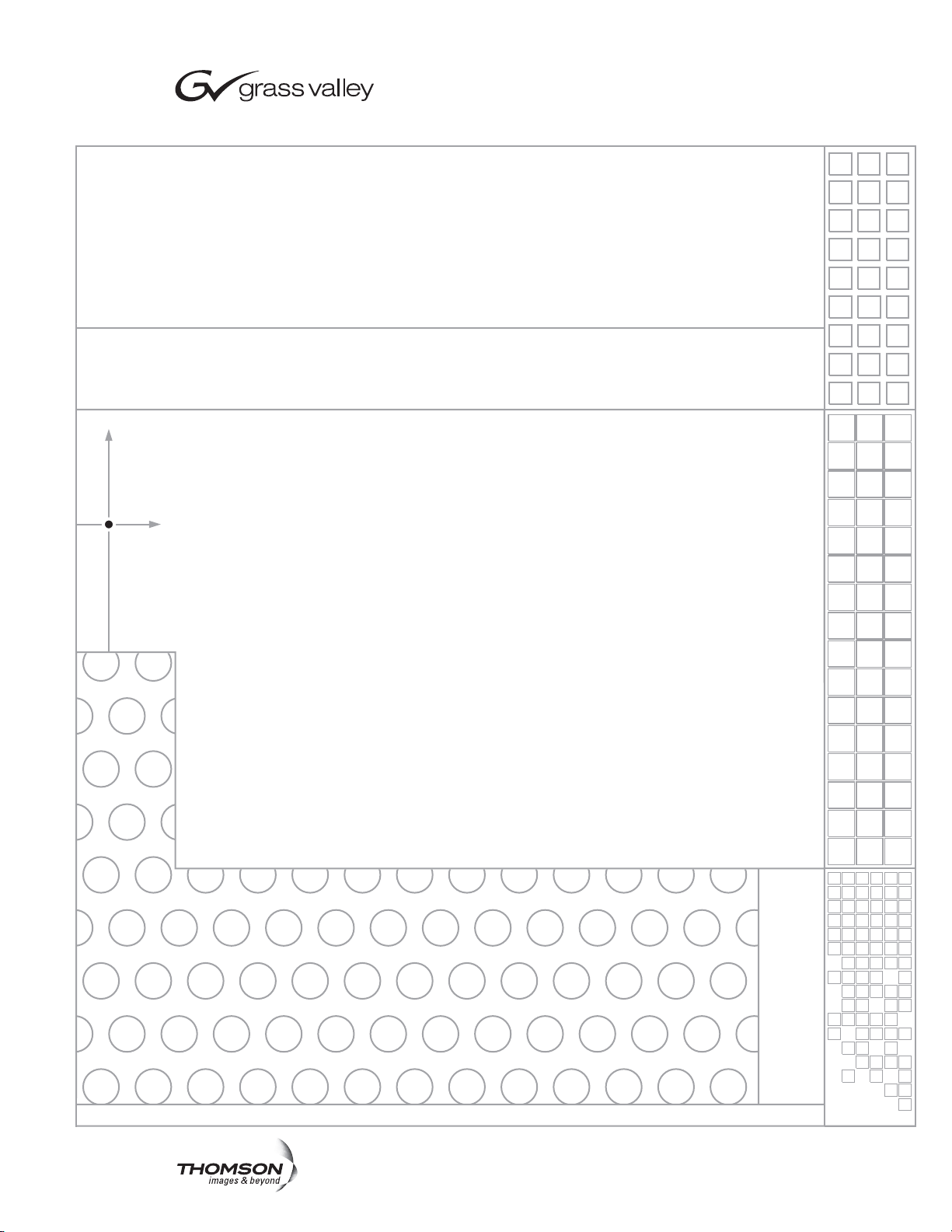
Prelude System Overview
Concerto Matrix Frame 1
Concerto Matrix Frame 2
Ethernet Switch
(customer supplied)
Up to 128
Sources
Up to 128
Destinations
Up to 32 Control Panels Total
per Prelude System
Up to 8
Acappella Frames
Up to 8 Levels Total
per Prelude System
Up to 8
Concerto Frames
100BaseT Ethernet
SW Installation and
Configuration PC
(customer supplied)
Prelude System
Acappella Matrix Frames
8382_04_r0
Up to 16
Sources
per Level
Up to 16
Destinations
per Level
48B Control
Panels
32 BPS Panels
PMB Control Panels
XY Control Panels
Acappella Remote
Control Panels
Front
Rear
Introduction
Prelude is a small router control system that operates with Concerto and
Acappella matrix frames and a variety of remote control panels (Figure 1).
Figure 1. Prelude System Diagram
Section 1
Prelude — Instruction Manual11
Prelude uses Ethernet for system communications. A customer supplied
100BaseT Ethernet switch and Cat 5 Ethernet cabling is required.
Page 12

Section 1 — Prelude System Overview
Prelude software applications are installed onto a customer supplied PC to
permit software updates and system configuration. After system configu
ration is complete, the PC can be used for monitoring the health of the
panels and matrix, but is no longer required and so may be removed for use
elsewhere. The Prelude configuration software is activated on a PC after its
installation by entering a registration code, which is valid for only that PC.
Prelude systems employ a distributed control system. Router configurations are stored in the Prelude control panels. These router configuration
files list the IP addresses of the matrices in that Prelude system, as well as
Level information and Source and Destination names. A copy of this router
configuration is sent from the panel to the matrices with the IP addresses
listed in that configuration. In fact, a Prelude control panel automatically
sends its router configuration to the matrices whenever that panel reboots.
Identical router configurations must be present on all control panels for
proper Prelude system operation.
Prelude 3.0 System Capabilities
-
• Off-line matrix and remote panel configuration using NetConfig with
registered Prelude plug-in.
• Support individual matrix sizes up to 128 x 128.
• Define up to 256 Sources and 256 Destinations.
• Control up to eight Concerto matrix frames or up to eight Acappella
matrix frames, for a total of eight levels per Prelude system.
• Supports all Concerto matrix boards.
• Supports Concerto Output Monitoring.
• Support all Acappella matrix frames (video, audio, or combination).
• Support up to 32 control panels of any of the following types:
Encore 48B, 32 BPS, PMB, XY, and UCP panels, Acappella Remote
Panels, and Kalypso KMD and KSD Remote Aux panels.
12 Prelude — Instruction Manual
Page 13

• Support control panel functionality (depending on the panel model),
including:
• Panel Enable.
• Destination Protect.
• Destination Soft and Hard Locks.
• Alphanumeric Names.
•Exclusion Sets.
• Destination Ganging.
•Joystick Override.
• Salvos (up to 256 salvos, with 1024 maximum elements supported).
• Source Exclusion by Destination (Rules)
• Kayak production switcher serial control.
• Acappella Optical Router matrix control.
• Soft Panels support (see the separate Soft Panels Instruction Manual for
specific information).
• Visual Status Display support (see the separate Visual Status Display
Instruction Manual for specific information).
• Native Protocol support (allows automation system control and status
monitoring from external devices that use Native Protocol), using
Ethernet or Serial communications.
Prelude 3.0 Limitations
• Prelude Destination Protects and Locks apply to all configured levels.
This matches the behavior of Encore control systems. Panels with dis
plays also report a “Locked” status for both hard locked and protected
Destinations.
• Prelude does not support the following Native Protocol commands:
AS, CH, CT, DA, QT, ST
• The PC monitor running the Prelude application must be set to 96dpi
(small fonts) to properly display the graphics. PC dpi display settings
can be accessed via: Start/Settings/Control Panel/Display/Settings/
Advanced/General.
• An extremely large number of rapid consecutive button presses (70+)
or rapid salvo Takes can overload the system. The system will not crash
but may miss a button press/release cycle, resulting in undesired
results (unintended Takes, for example).
-
Prelude — Instruction Manual13
Page 14

Upgrade Paths
Prelude is part of a family of related router products that offer easy upgrade
paths.
• Acappella is a small, single purpose router designed for out-of-box oper-
ation. It has a built-in control system that requires no configuration.
Various Acappella models are available with different hardware com
ponents that determine each unit’s routing capabilities.
•The Prelude control system software offers mid-range capabilities
intended for smaller facilities or localized applications. It can operate
with Acappella and/or Concerto matrix frames and employs Encore
and Acappella remote panels. The off-line matrix and panel configura
tion capabilities of Prelude provides increased routing system power
and flexibility.
• Encore is a full-function, facility-wide router control system that accom-
modates the widest variety of requirements on potentially huge scales.
Acappella matrix frames can become part of an Encore system. Simi
larly, Concerto matrix and control panels making up a Prelude system
can be upgraded to Encore, allowing incrementally enhanced routing
capabilities without the need to replace hardware components.
-
-
-
Prelude — Instruction Manual14
Page 15

Section 2
Installation and Initial Setup
Introduction
The Prelude control system does not use dedicated controller hardware,
which reduces system costs. Instead, control panels communicate directly
with the Matrix frame(s) via Ethernet. To accomplish this, compatible hard
ware and software must be installed and the components need to be properly connected. Finally, router and control panel configuration files are
created and sent to all the control panels.
This section covers hardware installation and basic configuration that
creates an operational Prelude system. Customizing this system for your
individual requirements is covered in
Section 3-Configuration Reference.
-
Installation Procedures Overview
Initial Shipment
Initial shipments of a Concerto based Prelude system has components that
are pre-configured at the factory with unique IP addresses. Acappella
system components ship with default IP addresses that will be the same for
each type of component.
For both these systems, initial installation and setup involves:
Install a customer provided Ethernet switch as part of a standalone
network and provide AC power to the switch.
Install the Concerto frame and/or the Acappella frame(s) in a rack and
provide AC power.
Install the remote control panels in racks and provide AC power.
Connect all Prelude system components to the Ethernet switch.
Prelude — Instruction Manual 15
Page 16

Section 2 — Installation and Initial Setup
Configure a customer supplied PC to operate on the default Prelude
network and connect it to that network.
Install NetConfig and appropriate Prelude files from the Compact
Router Control System Software CD onto the PC.
Resolve any duplicate IP addresses using NetConfig.
Name each device if desired, using that device’s web page.
Enter the license key for your Prelude system.
Create the Prelude system router configuration file.
Create control panel configuration files.
Send the same router configuration file to all the control panels.
Send the appropriate panel configuration file to each control panel.
Test system operation.
Back Ordered Shipments or Additional Equipment Purchases
Back ordered Prelude components, or newly ordered additional equipment
will ship with default settings that will need to be changed to integrate with
the rest of your system. Adding components to a Prelude system will
involve:
Install the new components in racks, provide power, and connect them
to the Prelude network.
Resolve any duplicate IP addresses for the new components using Net-
Config.
If you wish, you can name the new devices using their web pages.
If there are new Concerto boards or Acappella frames, reconfigure the
frame(s) for the new components. New router configuration files will
then need to be created and sent to all control panels. You may also
need to edit existing control panel configuration files to work with the
new frames, and then send them to the existing control panels.
Ensure compatible software resides on all system components.
Send appropriate panel configurations to the new control panels, or
create new control panel configuration files and send them.
Test system operation.
16 Prelude — Instruction Manual
Page 17
Hardware Installation
25 21 17 13 9 5 1
22 18 14 10 6 2
26 23 19 15 11 7 3
282730
2931
32 24 20 16 12 8 4
31 27 23 19 15 11 7
28 24 20 16 12 8
32 29 25 21 17 13 9
30 26 22 18 14 10563412
INPUTS OUTPUTS
EXP
IN
EXP
OUT
AUDIO/DATA
TDM
MON IN MON OUT
12
12
EXT COM2EXT COM
1
E-NET2E-NET
1
AES REF VID-REF 2 VID-REF 1
400W; 11.1A36-60V
+-
AC PWR 2 AC PWR 1
500W; 5A50/60Hz100-240V
ALARM
1 2 9 10
3 4 11 12
5 6 13 14
7 8 15 16
21 22 25 26
23 24 27 28
29 30 31 32 3 4 7 8
1 2 5 6
11 12 15 16
9 10 13 14
19 20 27 28
17 18 25 26
23 2417 18
21 2219 20
31 32
29 30
IN OUT
EXP. OUT
EXP. IN
112
2
OUTPUTS
INPUTS
IN OUT
MONITOR
AES BALANCED BA CKPLANE
+G+G
1 1 292 9 10 10
3 43 4 11 1211 12
5 65 6 13 1413 14
7 87 8 15 1615 16
21 2221 22 25 2625 26
23 2423 24 27 2827 28
29 3029 30 31 3231 32 3 3 474 7 8
1 1 252 5 6
11 1211 12 15 1615 16
9 109 10 13 1413 14
19 2019 20 27 2827 28
17 1817 18 25 2625 26
23 2423 2417 1817 18
21 2221 2219 2019 20
31 3231 32
29 3029 30
IN OUTIN OUT
EXPEXP. OUT. OUT
EXEXP.P. IN IN
112
2
OUTPUTOUTPUTS
INPUTINPUTS
ININ OUTOUT
MONITOMONITOR
AES BALANCED BAAES BA LANCE D BA CKPLANECKPLAN E
+G+ G +G+ G
252525 212121 171717 131313 95959 5 11
222222 181818 141414 101010 62626 2
262626 232323 191919 151515 111111 73737 3
282828
272727
303030
292929313131
323232 242424 202020 161616 121212 84848 4
313131 272727 232323 191919 151515 111111 77
282828 242424 202020 161616 121212 88
323232 292929 252525 212121 171717 131313 99
303030 262626 222222 181818 141414 101010556633441122
INPUTINPUTINPUTSS OUTPUTSOUTPUTSOUTPUTS
EXPEXPEXP
INININ
EXPEXPEXP
OUOUOUTT
AUDIO/DAAUDIO/DAAUDIO/DATATATA
TDTDTDMM
MON INMON INMON IN MON OUTMON OUTMON OUT
12121 2
12121 2
RATED CURRENT: 0.35 A
CAMERA JOYSTICK
OVERRIDE
FREQUENCY: 47-440 Hz
RATED VOLTAGE RANGE: 85-260 VAC
LAN
(Up to 32 Panels)
100BaseT Ethernet
Remote Control Panels
Rear
Front
SW Installation and
Configuration PC
(customer supplied)
Ethernet Switch
(customer supplied)
Video/Audio/Reference
Prelude System Cabling - Concerto Frame
Network
Terminate Video or Loop to
additional Frames
Terminate Audio or Loop to
additional Frames
Video
Ref In
Video Inputs
Video Outputs
Audio Inputs
Audio Outputs
AES Audio Board
(Level 3 Audio)
Concerto Frame
AES Audio Board
(Level 4 Audio)
AES
Audio
Ref In
Video In/Out ConnectionsVideo In/Out Connections
Similar to Level 1Similar to Level 1
Video In/Out Connections
Similar to Level 1
Audio In/Out ConnectionsAudio In/Out Connections
Similar to Level 3Similar to Level 3
Audio In/Out Connections
Similar to Level 3
Video Board
(Level 1 Video)
Video Board
(Level 2 Video)
8382_05_r0
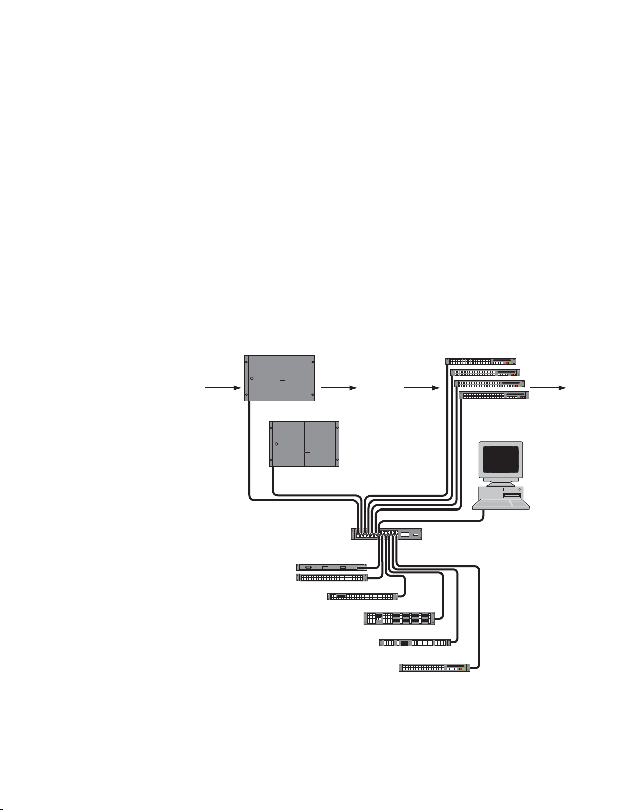
Refer to the separate Acappella Instruction Manual or Concerto Installation and
Service Manual for detailed instructions on hardware installation.
Hardware Installation
The following figures illustrate typical Pr
wiring will vary depending on the components making up your system.
Prelude/Concerto System Diagram
Figure 2. Prelude/Concerto System Example
elude systems. Actual system
Concerto Installation Notes
Prelude — Instruction Manual 17
• Some older Concerto boards may not report the correct matrix size
when the Prelude auto-configure feature is used. If this occurs the
correct matrix size can be entered manually during configuration.
Page 18
Section 2 — Installation and Initial Setup
RATED CURRENT: 0.35 A
CAMERA JOYSTICK
OVERRIDE
FREQUENCY: 47-440 Hz
RATED VOLTAGE RANGE: 85-260 VAC
LAN
Audio In
Audio In
Audio
Out
Audio
Out
Audio
Out
Audio
Out
Video In
Video In
Video
Out
Video
Out
Video
Out
Video
Out
100BaseT Ethernet
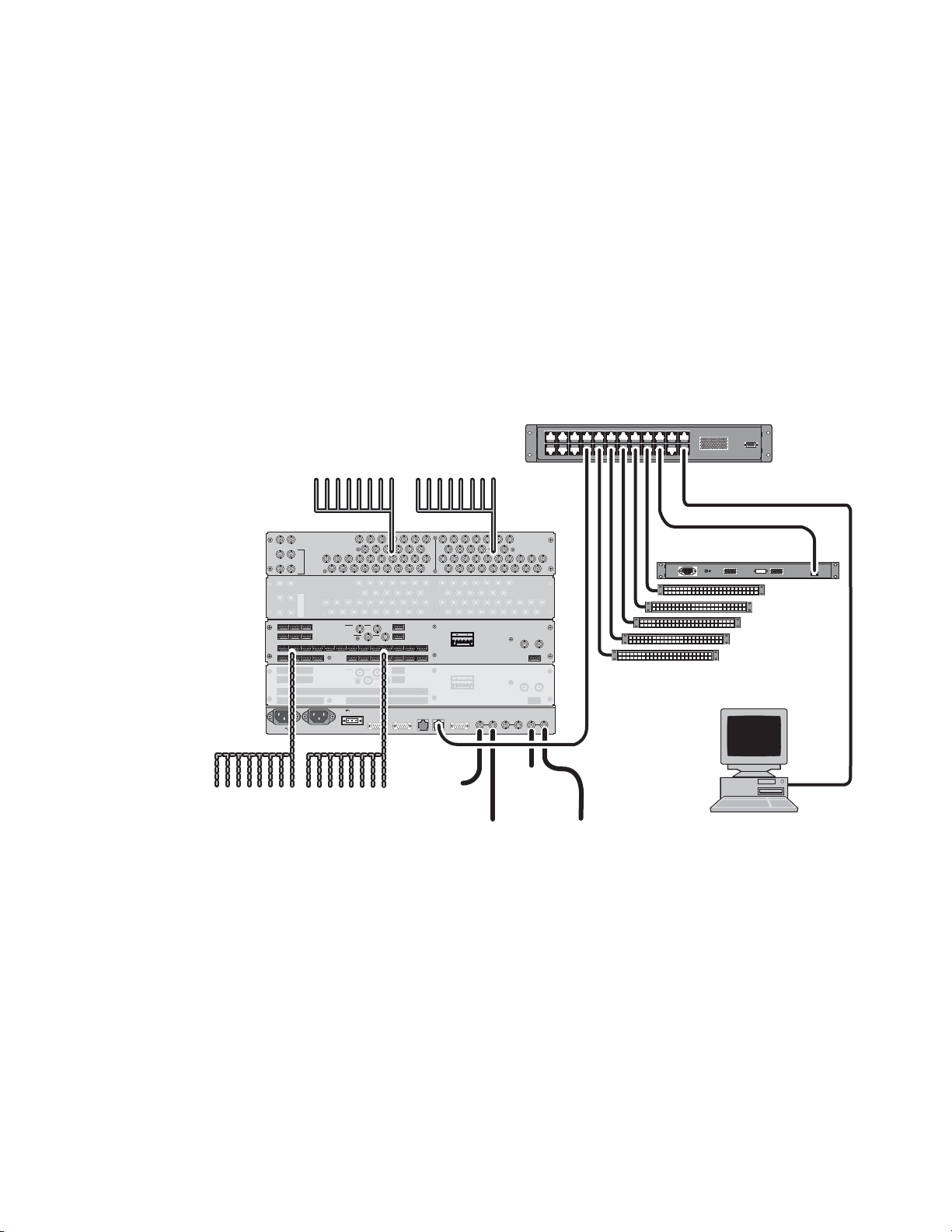
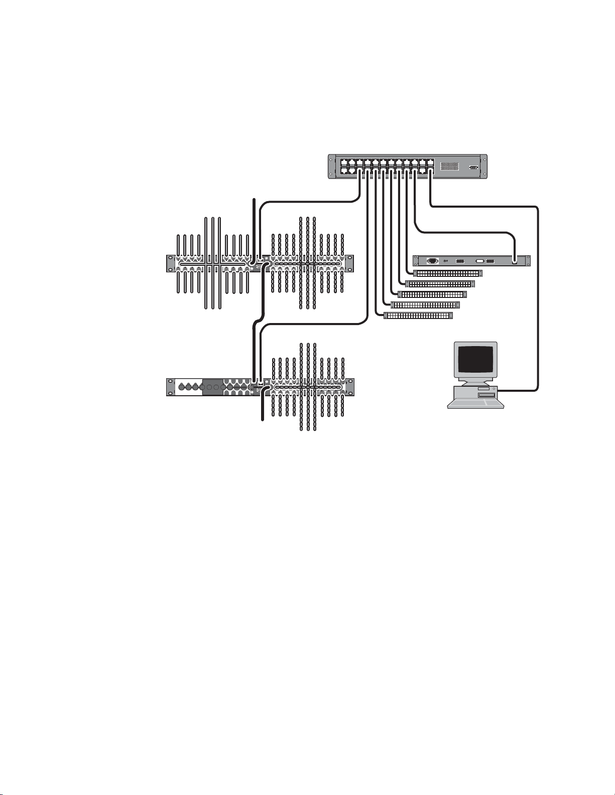
Video/Audio/Reference
Prelude System Cabling - Acappela Frames
Network
Ref
Term
Video
Ref In
Audio In
Acappella
AES Audio
Frame
SW Installation and
Configuration PC
(customer supplied)
(Up to 32 Panels)
Remote Control Panels
Front
Ethernet Switch
(customer supplied)
Rear
Acappella
SD Video
AES Audio Frame
Audio In
Audio
Out
Audio
Out
Audio
Out
Audio
Out
100BaseT Ethernet
Ref Loop
8382_06_r0
(Up to 8 Frames)
Prelude/Acappella System
Figure 3. Prelude/Acappella System Example
Acappella Installation Notes
Combined Concerto/Acappella Prelude System
• Each Acappella matrix frame can be configured with up to four levels,
but multiple Acappella frames cannot be combined into a single matrix.
A Prelude system with both Concerto and Acappella frames can be created,
with the following additional considerations:
• The default IP addresses of C
oncerto and Acappella frames are not in
the same network, and will need to be changed. See Prelude System
Default IP Addresses on pa
• Video and digital audio reference signals will need to
• Acappella matrix frames cannot be combined w
the matrix frames making up the Prelude system.
with other Acappella frames to form a combined matrix.
ge 20.
be looped to all
ith Concerto frames, or
18 Prelude — Instruction Manual
Page 19

Network Requirements
Ethernet Switch Specifications
A100BaseT Ethernet Switch and Cat 5 cabling are required. The fast
Ethernet (100 BaseT) on CAT 5 cables (UTP) can reach a maximum distance
of 100 Meters.
PC Requirements
A customer supplied PC is used for software installation and initial system
configuration. This PC must meet the following minimum requirements:
• 2 Ghz CPU
• 512MB RAM
• 40GB hard drive
Network Requirements
• 250MB free hard disk space
• Monitor with 1024x768 resolution
• 100BaseT Ethernet Network Interface Card
• Windows XP Professional (Service Pack 2)
• Logged in with Administrator-level pr
• Internet Explorer vers
After a full Prelude installation the folder
requires approximately 67 MB of disk space (Tab le 1);
Table 1. Prelude Installation Required Disk Space
Application Disk Space
Acappella 18 MB
Prelude 13 MB
NetConfig 8 MB
Concerto 4 MB
Soft Panels 12 MB
VSD 7 MB
All Applications 67 MB total
ion 6.0 or later
ivileges for the local machine
C:\Program Files\Grass Valley Group
Prelude — Instruction Manual 19
Page 20

Section 2 — Installation and Initial Setup
PC Network Configuration
The PC used must be configured to operate on the Prelude standalone network. This is accomplished
patible with the IP addresses
the first three octets of the IP address must be the same, and the last IP
address octet must be unique for each device on the network.
The exact method used to change the IP address of a PC varies, depending
on the computer
you should note down the existing values so you can easily reconfigure the
computer back to normal operation when finished using it with Prelude.
Prelude System Default IP Addresses
You need to know the IP addresses of your Prelude system components.
The default addresses as shipped from the Grass Valley factory are listed
below. However, the IP address of a device may have been changed since
its initial shipment.
by setting the IP address of the PC to be com-
of the Prelude system components. In general,
’s operating system. Before changing the PC’s IP address
Prelude Concerto Initial Shipment
Table 2. Prelude Concerto Based System Default IP Addresses
Device IP Subnet Mask
Concerto Frame Primary Controller 192.168.1.34 255.255.255.0 192.168.1.1
Concerto Frame Secondary Controller 192.168.1.35 255.255.255.0 192.168.1.1
First Control Panel 192.168.1.81 255.255.255.0 192.168.1.1
Each Additional Control Panel Usually increment last octet of IP add
CAUTION Concerto Controller redundant operation employs consecutive IP addresses.
The next higher IP address is reserved for this purpose and cannot be
assigned to another device on the network, even if the Concerto is not operating redundantly. Serious system communications problems can occur if
this next higher Concerto Controller IP address
Concerto system component IP defaults are compatible and will communicate without network configuration.
Subsequent shipments of Concerto components will ship with default IP
esses. If these components are added to an existing Prelude system
addr
network, duplicate IP conflicts may occur, which can be resolved using the
NetConfig application.
Defaults
Gateway
(not required for Prelude)
ress by one. (192.168.1.82,
192.168.1.83, etc.). However, duplicate IP addresses may occur.
is used on the network.
20 Prelude — Instruction Manual
Page 21

Software Installation and Network Configuration
Prelude Acappella Shipment Defaults
Table 3. Prelude Acappella Based System Default IP Addresses
Device IP Subnet Mask
Acappella Frame 192.168.0.40 255.255.255.0 192.168.0.1
Acappella Remote Panel 192.168.0.41 255.255.255.0 192.168.1.1
Encore Control Panels 192.168.1.60 255.255.255.0 192.168.0.1
Note The default Acappella frame IP address will not communicate with the default
Encore control panel address (the third octet is not the same), and all remote
panels shipped with Acappella systems have the same IP addresses. These
default values will need to be changed.
The NetConfig application can be used to discover devices on the network,
set their addresses, and resolve any duplicates. NetConfig operation is
described briefly later in this manual, and in more detail in the separate
NetConfig Instruction Manual.
Gateway
(not required for Prelude)
Software Installation and Network Configuration
Install NetConfig Application and Prelude Files on PC
NetConfig is a network configuration tool that is available for use with a
variety of Grass Valley products, including for example Prelude, Encore,
and several Modular Products. For Prelude, NetConfig is installed onto a
PC. This PC is then used for Prelude network configuration, software
installation onto Prelude system components, and Prelude system component configuration.
To Install NetConfig and Prelude files onto a PC:
1. Insert the Compact Router Control System Software CD into the PC’s
CD drive. The setup application will autorun when inserted.
2. Follow the instructions displayed on the screen. You will see a Welcome
screen, a License Agreement, and a Destination Location screen.
3. Keep the default install destination location and click Next>. The Select
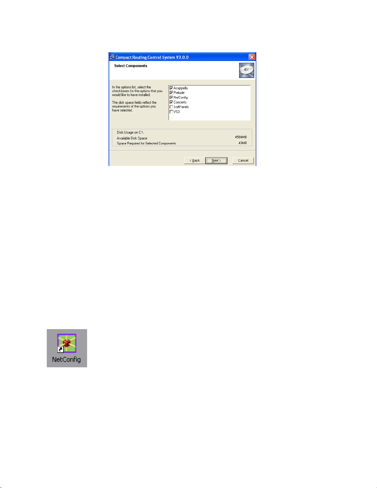
Components screen is displayed (Figure 4).
Prelude — Instruction Manual 21
Page 22
Section 2 — Installation and Initial Setup
Figure 5. NetConfig Icon
Figure 4. Select Components Screen
4. Ensure both the NetConfig and Prelude check boxes are selected, and then
select the remaining components appropriate for your system.
a. Select both Acappella Matrix and Concerto if your Prelude system has a
mix of both hardware types.
b. Select Acappella Matrix and de-select Concerto if your system has only
Acappella hardware.
c. Select Concerto and de-select Acappella Matrix if your system has
only Concerto hardware.
5. If you wish to install the any additional applications (Soft Panels and/or
VSD), select their check boxes. Licensing may be required to make full
use of these other applications.
6. Click Next>, then follow the remaining instructions shown on the screen.
The NetConfig software and Prelude files will be installed on your PC,
along with any other selected items.
7. After installation on the PC completes, a NetConfig icon will appear on
the desktop (Figure 5). Clicking on the icon launches NetConfig.
Note If Prelude is uninstalled with Windows Add or Remove Programs (it is listed
as Compact Routing Control System), NetConfig will also be removed. You
will need to reinstall NetConfig if you wish to use it with other applications.
22 Prelude — Instruction Manual
Page 23
NetConfig Overview
Prelude
Tab
IP View
Tab
Discover
Button
Name and
IP Address of
Computer Running
NetConfig
Missing
Device
Duplicate
IPs
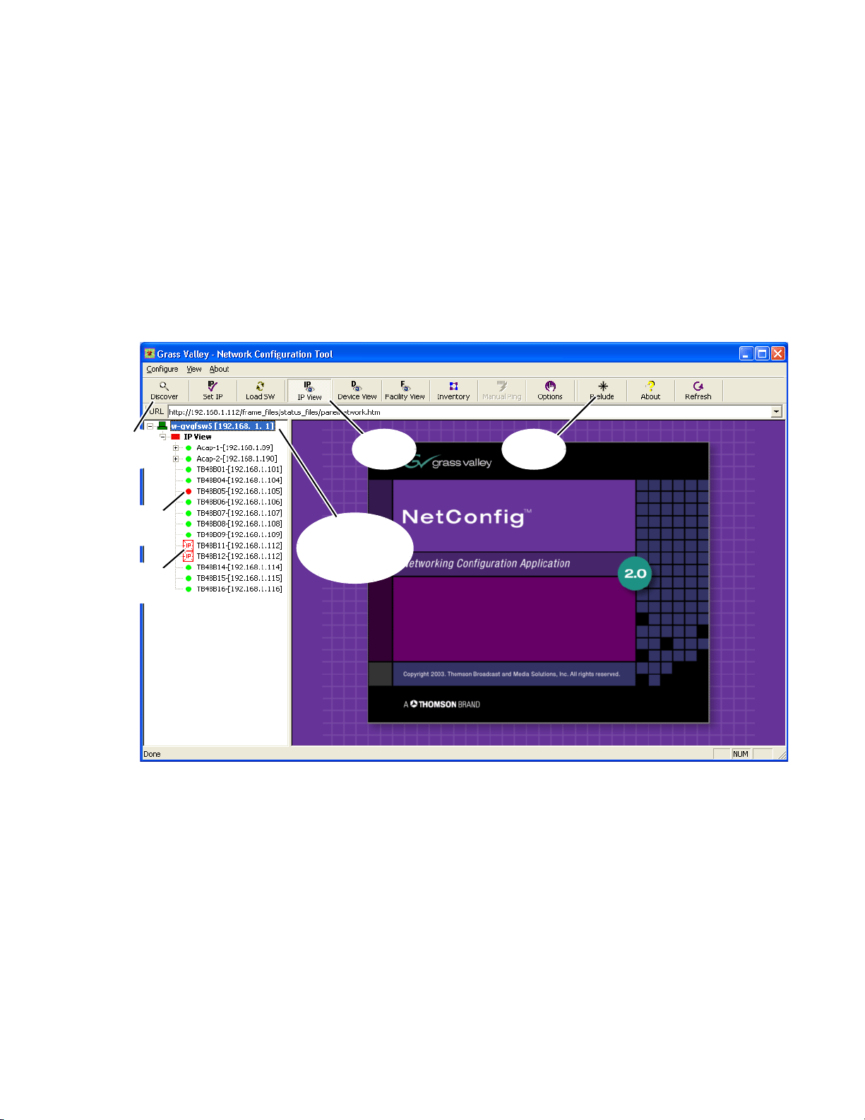
The NetConfig application is designed to make network configuration
simple. NetConfig discovers devices on the network, and these devices can
be configured remotely using the PC on which NetConfig has been
installed. NetConfig incorporates a web browser that displays web pages
served by the devices on the network. NetConfig is used for software
installation to these devices, and also provides rudimentary health checks
for these devices. Various NetConfig plug-ins are available for use with
specific Grass Valley products. The Prelude control system is one of these
plug-ins. Refer to Figure 6 for the following discussion.
Figure 6. NetConfig with Prelude Installed
Software Installation and Network Configuration
The NetConfig icon on the desktop can be used to launch the application.
The NetConfig application is also on the Start menu under Grass Valley
Group. If the Prelude check box was selected for the installation a Prelude
plug-in tab will be present at the top of the NetConfig window.
The left side of the NetConfig application scr
the devices on the network to which the PC is connected. The root of the
logical tree is the name and the IP address of the PC on which NetConfig is
running. The current status of each discovered device is reported by the
color of its icon. A red dot, for example, indicates a device is no longer communicating, which might mean it has been disconnected from the network.
een displays the logical tree of
Prelude — Instruction Manual 23
Page 24
Section 2 — Installation and Initial Setup
Different views of the devices are available, one or more of which can be
displayed with the
we will use the IP view in all the examples.
The right portion of the screen is the web browser view. When you click a
de
vice on the left, the home page for that device is displayed in the web
browser view.
IP View, Device View, and Facility View tabs. In this manual
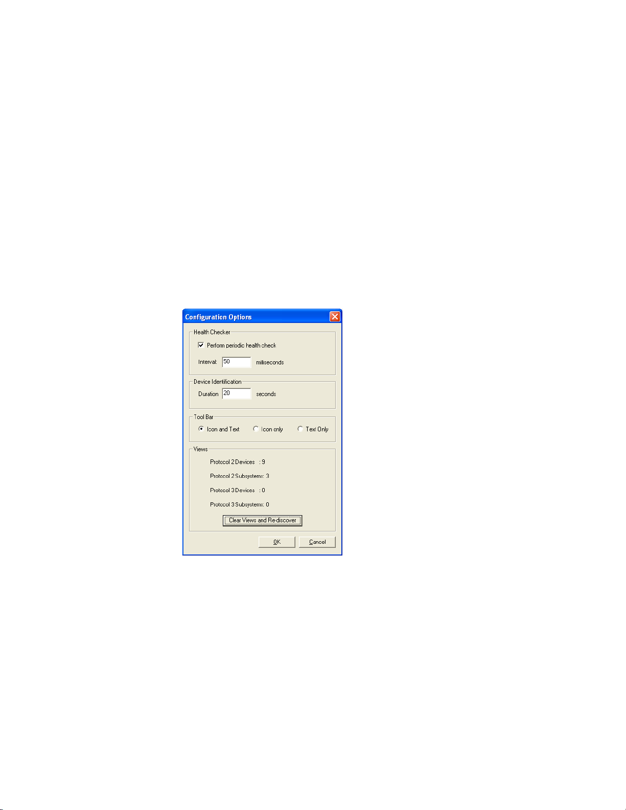
Pressing the
information on the left side of the screen. NetConfig remembers discovered
devices and reports their current status. If communication to a device is
lost, the icon for it is colored red.
Another useful discovery tool is avail
Clear Views and Re-discover button updates the information for only currently
communicating devices (Figure 7).
Figure 7. Option Tab, Clear Views and Re-discover Button
Discover tool bar button initiates a discovery that updates the
able by clicking the Options tab. The
The Set IP tab is used to set IP addresses of devices on the network, and the
Load SW tab is used to load software to the devices. The use of these two fea-
tures with Prelude are describe
Refer to the separate NetConfi
mation.
24 Prelude — Instruction Manual
d later in this manual.
g Instruction Manual for more detailed infor-
Page 25

Software Installation and Network Configuration
Set IP Addresses and Resolve any Duplicates
The IP address of a Prelude system component can be changed using NetConfig, or using the web page of that device. To use the direct web page
method. however, you need to know the existing IP address of that device.
NetConfig is convenient to use for IP address changes because it displays
all the devices on the network, making them easy to access.
Set Compatible IP Address Subnets
NetConfig will report the presence of devices on a different subnet (in general, devices with IP addresses that have varying third octet numbers), but
these devices will all need to be on the same subnet to work with other
Prelude devices. For example, if your system has both Concerto and Acap
pella frames, you can change the default Acappella frame IP addresses to
have a “1” as the third octet, which will match the Concerto default subnet.
1. Select the NetConfig Set IP icon on the toolbar or the Device IP
Addresses in the Configure pull-down.
2. Highlight the device with an incorrect subnet IP address.
-
3. Click Edit, then change that device’s IP address to be unique, but have
the same third octet as the other Prelude devices.
4. Click Apply Changes. The device resets, and the new IP address will be
reported in the left pane of NetConfig screen.
Resolve Any Duplicate IP Addresses
Resolving duplicate IP addresses is easily accomplished with NetConfig. If
a device is installed on the network with the same IP address as another
device, when the new device is discovered a warning message will be dis
played. The IP View will also show the two devices with the same address
with an IP symbol as shown in
new devices with factory default IP addresses are installed on the network.
1. Select the NetConfig Set IP icon on the toolbar or the Device IP
Addresses in the Configure pull-down.
2. Highlight one of the devices with a duplicate IP address.
3. Click Edit, then change the last octet of that device’s IP address to be
unique. The first three octets of all the IP addresses must be identical,
so all the devices are on the same network.
-
Figure 6 on page 23. This can occur when
4. Click Apply Changes. The device resets, and the new IP address will be
reported in the left pane of NetConfig screen.
Prelude — Instruction Manual 25
Page 26

Section 2 — Installation and Initial Setup
Label Each Device’s IP Address
When all devices have unique IP addresses, it can be extremely helpful to
label each device with its currently assigned IP address. Removable adhe
sive labels are recommended, since the IP address may be changed in the
future.
Identifying Control Panels
To identify a specific control panel when several are connected at once, you
can right click on the device name in NetConfig and choose
That panel’s front panel buttons will blink on and off alternatively.
Touching any front panel button restores normal button tally.
Alternatively, to identify a panel you can send it a reset command and see
which one’s front panel buttons all go off and back on.
Name Devices
You can give the Prelude components descriptive names, if you wish. This
can be helpful during configuration, especially for control panels which
may be located at different locations that require different configurations.
Devices are named using that device’s web page.
-
Identify Device.
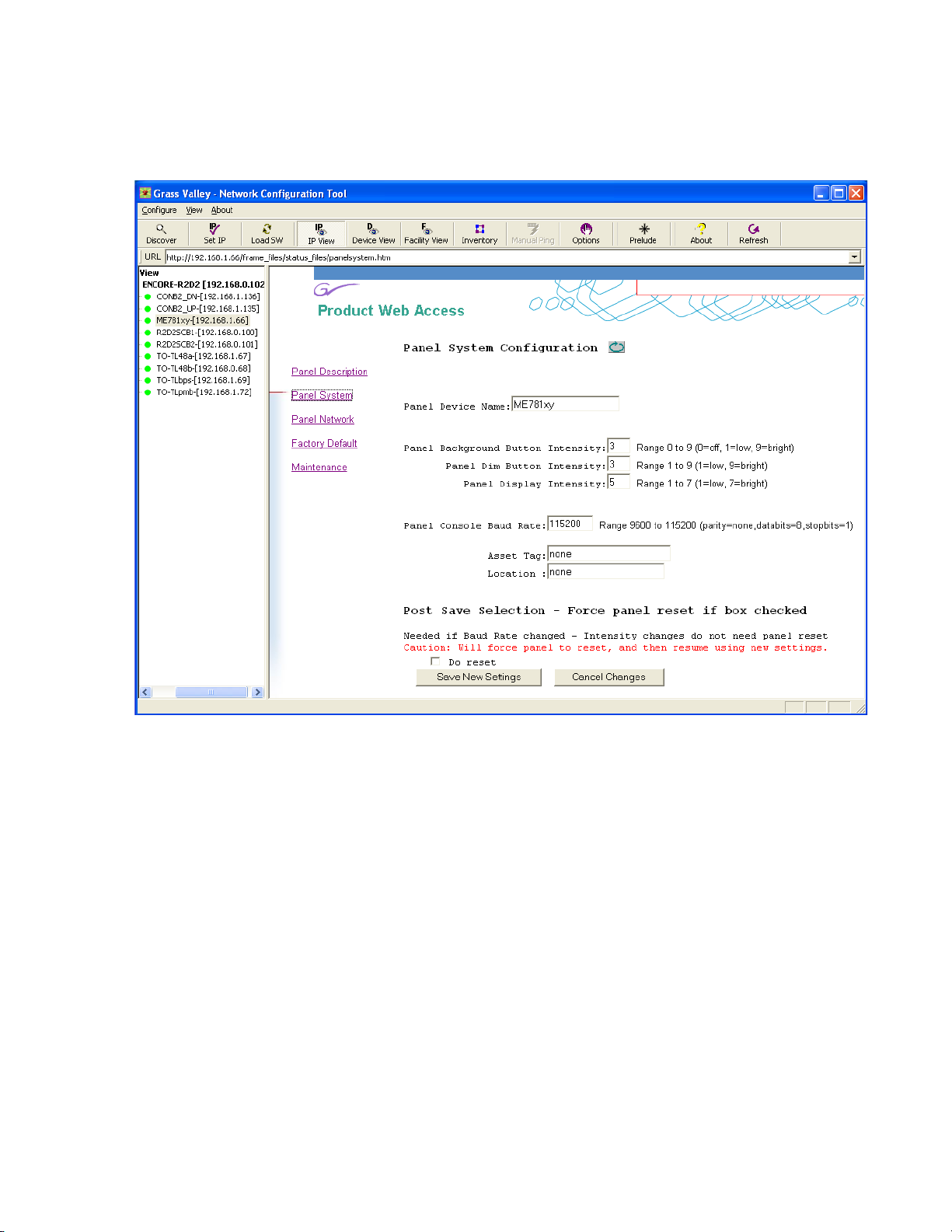
1. In NetConfig, select the device you wish to name on in the left pane,
then click on
Panel System or Matrix System (depending on device type).
26 Prelude — Instruction Manual
Page 27
Software Installation and Network Configuration
2. Type in an 8 character or less name in the Device name field (Figure 8).
Figure 8. Control Panel System Web Page
3. Click Save New Settings. The panel does not need to be reset if only its
name is changed.
4. Click Discover to update the view. The new name will appear in the left
pane.
5. Repeat for any the other devices that you wish to re-name.
Prelude — Instruction Manual 27
Page 28

Section 2 — Installation and Initial Setup
Prelude Software Compatibility
On newly shipped Prelude systems, the latest software should have been
loaded onto all the components. Software versions for each component
must be compatible for proper operation. The following software components have been tested for compatibility
Table 4. Prelude System Compatible Versions
Component Software Version
Prelude
Software
V3.0.0
NetConfig 2.0.10
Concerto Frame 1.7.5.2
Acappella Frame 3.0.0
Acappella Remote Panel Prelude 3.0.0
Encore Control Panel Prelude 3.0.0
Kalypso Control Panel Prelude 3.0.0
Soft Panels 3.0.0
Visual Status Display 1.1.0
Prelude Version 2.0 and 3.0 Backward Compatibility
The router configuration file format has changed in Prelude 3.0 to support
new features. Newer Prelude 3.0 version router configuration files will not
work on systems downgraded back to Prelude 2.0. Though downgrading
to an earlier version of software shouldn’t be necessary, backing up your 2.0
router configuration files before you update to Prelude 3.0 software can be
helpful just in case.
Router configuration files can be backed up
folder under a new name in a secure location (perhaps a removable
memory stick). The folder is located at:
C:\Program Files\Grass Valley Group\
Prelude_Install_Directory\Route_Config
To regain access to the router configuration file
grade, rename existing folder with that name, copy the backed up folder to
that loc
ation and restore its original Route_Config file name.
Check Software Versions
On newly shipped Prelude systems, the latest software should have been
loaded onto all the components. Software versions must be the same for
each device type for proper operation. To check the software versions:
by saving the Route_Config
s after a Prelude 2.0 down-
1. Click the NetConfig Load SW toolbar button.
28 Prelude — Instruction Manual
Page 29
Software Installation and Network Configuration
Current
Software
Version
Current
Software
Versions
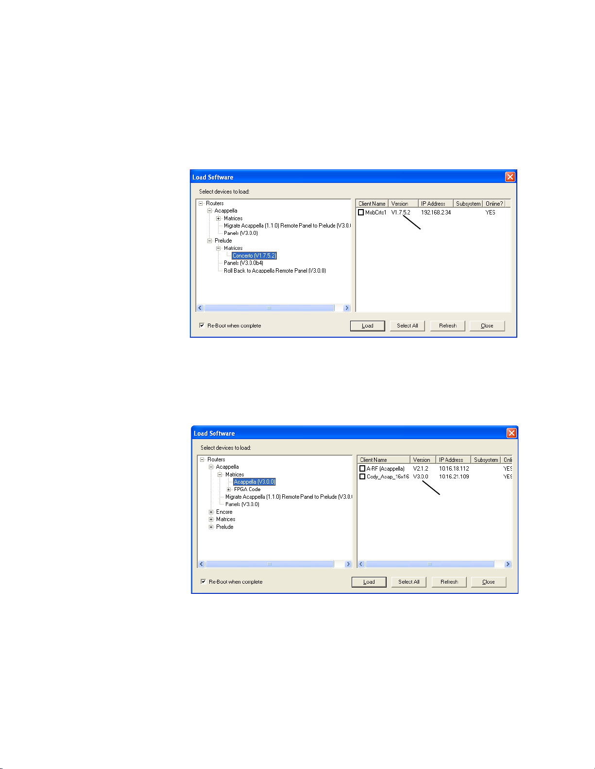
2. Check the frame software versions.
a. On Concerto systems, navigate to Routers/Matrices/Concerto and
click on
Concerto Matrix (100BaseT). The Concerto frame will be listed
on the right with its IP address and currently loaded software
version.
Figure 9. Concerto Frame Software Version
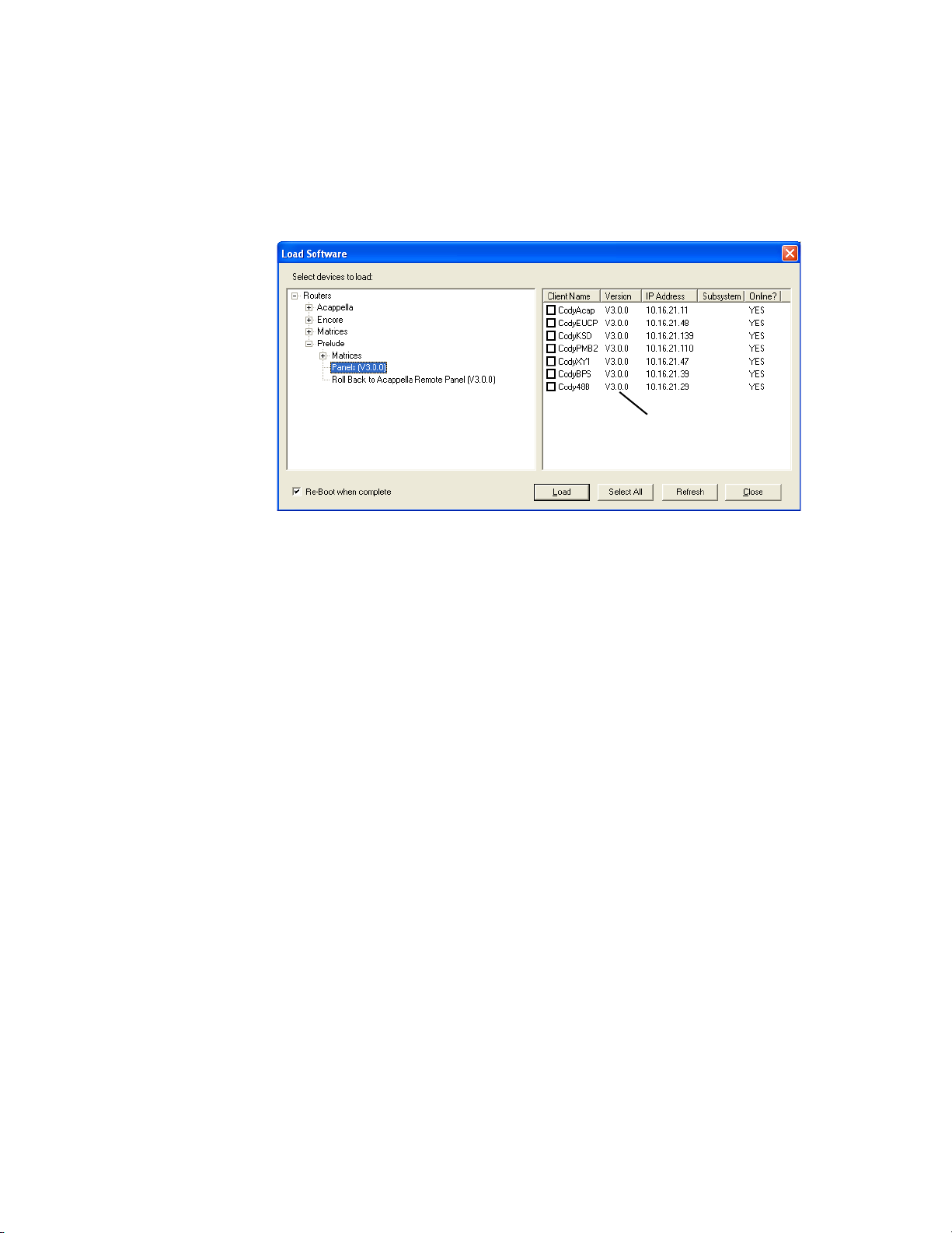
b. On Acappella systems, navigate to Routers/Acappella/and click
on
Acappella Matrix. All the Acappella frames will be listed on the
right with their IP addresses and software versions.
Figure 10. Acappella Frame Software Version
Prelude — Instruction Manual 29
Page 30
Section 2 — Installation and Initial Setup
Current
Software
Versions
3. Check the control panel software versions. Navigate to Prelude and click
Panels. Control panels with Prelude software installed will be listed
on
on the right with their IP addresses and the version of the Prelude
software will be reported.
Figure 11. Control Panel Software Versions
Note Other items on this menu are used to convert older Acappella or Encore
control panels for use by Encore. See Panel Conversions o
more information.
Update Any Older Software
If any older versions of software were found the devices need to be
updated, using the following procedure.
1. With the latest version of Prelude software and NetConfig installed on
the PC configured for the Prelude network, run NetConfig and click on
the
Load SW toolbar button.
2. Navigate to the frame or control panel as described above (Figure 9,
Figure 10, and Figure 11) and select the check box(s) for the older
device(s).
3. Make sure the Re-Boot when Complete box is checked, then click Load. The
software will be loaded to the device(s) over the network and the
device(s) will be reset.
4. When done, confirm again that the latest software is loaded on all the
Prelude components.
n page 51) for
30 Prelude — Instruction Manual
Page 31

Prelude Registration
About
Prelude
Button
If the Prelude control system is not registered, the following prompt
appears the first time you click on the Prelude tab.
Figure 12. Unregistered Message
When Prelude is not registered, you will not be able to Get or Send router
or control panel configuration files from or to the Prelude control panels.
The Prelude control system plug-in is activated with a license key. Each
license key
Device ID of that specific PC. You will need to determine the Device ID of
your PC and provide that exact number to Grass Valley Sales. They will
then generate the key and send it to you. Entering this key into NetConfig
will activate the Prelude configuration functionality on that PC.
Software Installation and Network Configuration
is valid for an individual PC, and is generated based on the
The complete procedure to register your Prelude control system consists of
the following
1. With NetConfig installed on the PC you intend use with Prelude, click
on the Prelude tab. Click
displayed. The Prelude User Interface (UI)
Figure 13. Prelude User Interface
steps:
OK if the Unregistered Message (Figure 12) is
is then shown (Figure 13).
Prelude — Instruction Manual 31
Page 32

Section 2 — Installation and Initial Setup
2. Click the About Prelude button located at the top right of the Prelude UI
pane. Do not confuse this button with the other two About buttons
located above and to the left.
3. The About Prelude pane will be displayed (Figure 14).
Figure 14. About Prelude Pane
4. Click on the Register... button to display the Prelude UI Registration
pane. The Device ID of the PC is reported here (Figure 15).
Figure 15. Prelude UI Registration Dialog Box
5. Contact Grass Valley Sales by email or phone (refer to the back of the
title page of this manual for the current contact methods) and provide
the exact Device ID number. After your purchase has been confirmed,
a license key will be generated and sent to you.
6. Enter the License Key exactly (including dashes) in the Prelude UI
Registration Pane field displayed and click
correctly and matches the Device ID it will be accepted and the
following valid key message will be displayed (Figure 16).
Figure 16. Valid Key Message
7. Click OK twice. You are returned to a fully operational Prelude UI.
Submit. If the key is entered
32 Prelude — Instruction Manual
Page 33

System Identifier
If your Prelude system must run on a network shared by an Encore system
or other separate Prelude or Acappella systems, you can isolate them from
one another by assigning different ports for each system. This can be
accomplished using the
tion web page (Figure 17).
Figure 17. Concerto Network Configuration Page, with System Identifiers
Software Installation and Network Configuration
System Identifier controls on the Network Configura-
System Identifier for Single Systems
Leave the System Identifier setting to Default for all devices of a Prelude
system running on its own network.
System Identifier for Concerto Frames on a Shared Network
On a Concerto frame web page, the System Identifier controls are displayed
when a system type of
Prelude is selected, and are hidden if Encore is selected.
The easiest way to isolate multiple systems
Identifier buttons (Default, 1 - 5) to all the components of the first system,
and then assign a different button to all the components of the next system.
Prelude — Instruction Manual 33
is to assign one of the System
Page 34

Section 2 — Installation and Initial Setup
The Matrix Control Port Number reports the actual port that will be used by the
device. For example, if you wish to run a Prelude system on the same
network as an Encore system, you can choose button
Acappella and/or Concerto frames and all the control panels used by Pre
lude. The Encore system can continue to use the default port setting (6050).
Note All components on an individual system must use the same System Identifier
(port) number.
Alternatively, you can assign a specific port numbe r to a devi ce by ch oosing
Manual Select, which opens a text entry field. This feature is intended only
for qualified system administrators experienced with network configura
tion.
System Identifier for Control Panels on a Shared Network
Because the same port number must be used by all devices of a Prelude
system, if you change a matrix port number you must also change them on
all that system’s control panels. Go to the Network Configuration web page
for each panel and select a matching System Identifier or manually assign
it the same port number.
1 (port 6051) for the
-
-
Broadcast Select
Broadcast select determines the communications mechanism used by the
system.
Note All components on an individual system must use the same Broadcast Select
System Broadcast Select on Small Systems
Leave this setting at Use Broadcast if your Prelude system has only a small
number of control panels (three or less).
Note The Use Broadcast setting should NOT be used if an Encore system is also
System Broadcast Select on Larger Systems
Selecting Use Multicast makes this device employ a more efficient networking mechanism, useful for systems with several control panels.
settings.
present on the network.
34 Prelude — Instruction Manual
Page 35

Create Router Configuration
On a new Prelude system, with all the devices present on the network,
loaded with the latest software, and the Prelude license key activated, you
can now configure the Prelude system to make it operational.
Sample Configuration Files
Sample configuration files are included on the software CD. These files can
be used to learn about Prelude configuration, or as a starting point for creating a new configuration. Ta bl e 5 lists the configuration files available at
the time of publication. Additional sample files
existing files may be removed. Each sample Router config file has a
matching Panel config file, with similar names.
Create Router Configuration
may be added, however, or
The sample files are available from the Pr
Load Router Config From File and Load Panel Config From File.
Table 5. Sample Prelude Configuration Files
Type Name Description
Router Config
Panel Config
Concerto Configuration
Concerto frames can be equipped with various boards, permitting different
types and combinations of signal routing. Basic configuration consists of
assigning these boards to levels, defining the matrix size of each level, and
assigning and naming the Sources and Destinations. Prelude systems that
employ Concerto frames store the router configuration information on the
control panels.
Note To control two Concerto boards as a single level, the boards must be installed
in adjacent slots.
32VKAA
64VA
Default
elude UI by selecting
32 x 32 Concerto matrix with four levels
Frame IP address 192.168.1.34.
64 x 64 Concerto matrix with two
Frame IP address 192.168.1.34.
A default configuration for each panel type is available for
(Video, Key, AES1/2, AES3/4).
levels (Video, AES1/2).
loading.
Assign Hardware to Levels
1. Run NetConfig with the Prelude option registered.
2. Click on the Prelude button, then click on the Levels tab.
3. In IP view on the left, navigate and click on the Concerto device to
reveal the installed boards.
Prelude — Instruction Manual 35
Page 36

Section 2 — Installation and Initial Setup
4. Drag a board on the left to the level you want to use to control it on the
right. Data for that board will be automatically filled in (Figure 18).
Figure 18. Concerto Level 1
5. If you want to control another adjacent board of the same type with the
same level, just drag its icon to the same level. Or, if you want to divide
the control of a single board between two levels, drag the same board
icon a second time to a different level.
6. Assign all the remaining boards installed in the Concerto frame to the
desired levels (Figure 19). Level names are entered automatically. If you
edit them, each level must have a unique name.
36 Prelude — Instruction Manual
Page 37

Create Router Configuration
7. If you configure the levels by dragging the board icons, you do not need
to deal with Matrix numbers. They are entered automatically. However,
if you enter level configuration data manually the matrix number has
to be specified correctly. The rule is to use the lowest slot number of all
the boards being used for that level. For example, if you want to use
boards in slots 2, 3 and 4 for a level, the Matrix field should be set to 2.
If you want to use only the board in slot 3 for a level, the Matrix field
should be set to 3.
Figure 19. Concerto Levels 1, 2, and 3
Prelude — Instruction Manual 37
Page 38

Section 2 — Installation and Initial Setup
Define Sources
8. Click on the Sources tab, then click on the first field of the spreadsheet
and enter the name of your first Source, ending the name with a
number (Figure 20).
Figure 20. Concerto Source Name
9. You can now use the fill series feature to automatically enter ascending
names for Sources. Select on the field you just named, then shift click a
group of fields below to select all of them (Figure 21).
Figure 21. Concerto Source Multiple Selections
38 Prelude — Instruction Manual
Page 39

Create Router Configuration
10. Right click on the top field, then select Increment Down (Figure 22).
Figure 22. Concerto Source Name Fill Series
11. The fields will be filled with ascending Source names (Figure 23).
Figure 23. Concerto Source Ascending Names
You can use descriptive names (Cam 1, VTR 1, etc.) and Fill Series will
complete your naming scheme for the selected name fields with
ascending numbers.
Prelude — Instruction Manual 39
Page 40

Section 2 — Installation and Initial Setup
12. You can similarly assign Source connectors to the named Sources by
entering the first number in each column then fill the series (Figure 24).
If you divided a board into two levels, the connector numbers for the
added
board.
Figure 24. Concerto Source Connectors Filled In
level will typically start with the next higher connector on that
13. In this example the Destination connectors will be like the Sources, so
you can copy and paste the fields. Select all the Source connector fields
for all the levels, then right click and choose
Figure 25. Fields Selected for Copy.
Copy (Figure 25).
40 Prelude — Instruction Manual
Page 41

Define Destinations
14. Click on the Destinations tab. The Destinations can be named the same
way as the Sources. Once named, select all the Destination connector
fields, then right click and choose
(Figure 26).
Figure 26. Fields Selected for Copy.
Create Router Configuration
Paste to enter the values copied above
Global, Input, and Output Attributes
Concerto matrices support additional configuration options. Global attributes (reference signal standards) are accessed from the Levels tab by
cking on the
cli
Figure 27. Global Matrix Attributes
Global Matrix Attributes button (Figure 27).
Input and Output attributes are accessed from the Sources or Destinations
tabs by clicking on a Source or Destination Level cell supporting additional
Prelude — Instruction Manual 41
Page 42

Section 2 — Installation and Initial Setup
configuration, and then clicking on the Input Attributes or Output Attributes
button near the top of the screen.
AES modules allow setting parameters for Input Attributes (Figur
Figure 28. AES Input Attributes
Digital Video modules allow setting parameters for Output Attributes
(Figure 29).
Figure 29. Digital Video Output Attributes
e 28).
42 Prelude — Instruction Manual
Page 43

Save Router Configuration File to PC
15. With the levels, Sources, and Destinations defined you should now
save the configuration file to the PC. Click on
file name prompt will appear (Figure 30).
Figure 30. Router Configuration File Name Prompt
Create Router Configuration
Save Router Config to File. A
16. Enter a name for the router configuration file and click Save. The file is
now safely stored on your PC’s hard drive.
You can delete an existing configuration fil
it in the lower pane and clicking
Acappella Configuration
Acappella frames have fixed hardware. Different groups of frames are purchased, depending on what type and how many signals are to be routed.
Be
cause of this separate frame design, it is not possible to combine multiple
Acappella frames into one large matrix, as can be done with multiple
boards in a Concerto frame.
Configuration of Acappella frames under
the same as a Concerto frame. If more than one Acappella frame is resident
in the system, each will appear in NetConfig as separate devices with different IP addresses. Simply treat each dev
certo board, except for the one restriction described above.
If you have multiple Acappella frames equipp
panels, these panels may need to be configured directly using the Acappella frame web page. See page 51 for more information.
e if you wish by highlighting
Delete.
Prelude control is accomplished
ice the same as if it were a Con-
ed with built-in local control
Prelude — Instruction Manual 43
Page 44

Section 2 — Installation and Initial Setup
Send Router Configuration to All Panels
The router configuration file now needs to be sent to all the control panels
included in your Prelude system.
CAUTION The same router configuration must be sent to all Prelude system control
panels. Identical configurations are required for consistent system operation.
All panels must be connected before the router configuration is sent. If a disconnected panel with an old configuration is re-connected, it will send that
old router configuration to the matrices, which could adversely affect Prelude
system operation.
1. Make sure the correct router configuration file is loaded into the
Prelude UI. If necessary, click on the
select the router configuration you saved and click
2. Click on Send Router Config to Control Panel, ensure that all the panels are
connected and selected, make sure the
checked, and then click
be sent to each panel in turn.
Load Router Config from File... button,
Load.
Re-Boot when complete box is
OK (Figure 31). The router configuration file will
Figure 31. Control Panels Selected to Receive Router Configuration File.
Create Panel Configurations
Prelude panels need to know what the router matrix consists of, and then
the specific control capabilities of that panel over that router can be defined.
To accomplish this, the router configuration must first be loaded into the
Prelude UI. This provides information required to configure the panel.
Later the new panel configuration is sent to each control panel.
Note Sample Panel configuration files are included on the software CD. See
Sample Configuration Files o
44 Prelude — Instruction Manual
n page 35.
Page 45

48B Panel Configuration Example
The 48B style panel will be used as an example on the following pages.
Other panels with different feature sets are described in
Section 3-Configuration Reference.
1. Click on the Load Router Config from File... button, select the router
configuration you saved earlier and click
2. Click on the 48B Panel tab. This brings up a blank panel configuration
screen(Figure 32). Default values will be assigned to the flags and
attributes.
Figure 32. Blank Panel Configuration Screen
Create Panel Configurations
Load.
Prelude — Instruction Manual 45
Page 46

Section 2 — Installation and Initial Setup
3. To configure the panel buttons, you assign a function and, if
appropriate, a selection to each button, using similar techniques used
earlier to configure the router Sources and Destinations. Select a range
of Function fields and right click (Figure 33).
Figure 33. Set Button Function
4. Select Set Function. A pane will appear listing the available functions.
Choose
Figure 34. Button Function Selection Pane
Src Select (Figure 34).
46 Prelude — Instruction Manual
Page 47

Create Panel Configurations
5. Now highlight the Selection column for those buttons, right click, and
choose
Figure 35. Set Button Selection
Set Selection (Figure 35).
6. A pane appears listing the Sources available in the currently loaded
router configuration file. Choose a range of Sources for the highlighted
buttons (Figure 36).
Figure 36. Button Source Selection Pane
Prelude — Instruction Manual 47
Page 48

Section 2 — Installation and Initial Setup
7. Click OK. The Sources will be assigned to those buttons. Continue this
process until all the buttons for the panel have been configured
(Figure 37). Additional control panel attributes
at the bottom of this screen. These features are described in
Section 3-Configuration Reference.
Figure 37. Completed Control Panel Configuration
and flags are available
48 Prelude — Instruction Manual
Page 49

Create Panel Configurations
8. With the control panel configuration completed you should now save
the configuration file to the PC. Click on
name prompt will appear (Figure 30).
Figure 38. Router Configuration File Name Prompt
Save Panel Config to File. A file
9. Enter a descriptive name (8 characters maximum) for this particular
control panel configuration file and click
stored on your PC’s hard drive.
You can delete an existing configuration fil
it in the lower pane and clicking
10. You can now create different control panel configuration files with
different capabilities for use at different locations at your facility.
Remember to name each configuration file with a descriptive name and
save each one to the PC before you create the next one.
Attributes and Flags (Exclusions)
Additional Attributes and Flag controls are available on the lower part of
the screen. These controls affect various aspects of panel operation, and will
vary depending on the type of panel.
In particular, various Exclusions may be
to control selected Destinations, levels, or salvos. If an item is excluded, it
will not appear on the button configuration selection menus described
above. If an excluded item is present on a panel, that item’s current state
will be reported but you will not be able to change its state from that panel.
Save. The file is now safely
e if you wish by highlighting
Delete.
available to limit a panel’s ability
Configuring Encore Control Panel Types Other Than 48B
Other Encore panel types have different feature sets, and so may require
additional configuration steps, which generally involve Attributes and
Flags settings.
Prelude — Instruction Manual 49
Page 50

Section 2 — Installation and Initial Setup
Refer to Section 3-Configuration Reference for information about Attributes
and Flags and the differences between the
Send Panel Configuration to Each Panel
The appropriate control panel configuration file now must be sent to each
control panel.
1. Click on the Load Panel Config from File... button, select the appropriate
panel configuration and click
2. Now click on the Send Panel Config to Control Panel... button. A selection
pane listing all the available panels of that type will appear (Figure 39).
You can select a single panel, or if a gr
functionality you can select just the ones you want using standard
Windows methods (
Figure 39. Control Panels Selected to Receive Panel Configuration File.
various Encore panel types.
Load.
oup of panels share the same
Shift for adjacent items, Ctrl for individual items).
Note All Acappella remote panel types will be displayed (8x1, 16x16, etc.). You
should select only panel(s) that match the configuration type you have
created before you send the configuration to Acappella panel(s).
3. Make sure the Re-Boot when complete box is checked, and click OK. The
panel configuration files will be sent to the selected panels in turn.
50 Prelude — Instruction Manual
Page 51

Test System Operation
With all the panels loaded with the router and panel configuration files,
your Prelude system should be completely operational. A couple simple
tests include:
• While monitoring a Destination, select that Destination on any control
panel, change the Source for that Destination on that panel, and see or
hear the signal change for that Destination. All control panels that have
buttons delegated to that Destination will immediately tally a new
Source button (provided that new Source is mapped to the Source
buttons on that panel).
• Select a single level on any panel, select a Destination, and change its
Source. Only that level’s signal will change, and split tally lighting will
be reported on all control panels delegated to that Destination.
Acappella Local Panel Configuration
Test System Operation
Panel Conversions
If you have multiple Acappella frames configured under Prelude control,
and these frames are equipped with local control panels, and you wish to
use these panels for multi-level Takes on different Acappella frames, they
will need to be configured individually. Local Acappella panels cannot
receive configuration files. Configuration of Local Acappella panels is
accomplished using the web page for each Acappella frame. Refer to the
separate Acappella Instruction Manual for information on how to configure
Acappella frames.
Older Encore panels can be converted for use with Prelude by installing
Prelude software. Other panel conversion paths are possible, depending on
what software versions have been installed onto the PC running Net
Config. You will need to have the “to” version of software present on the
PC in order to upgrade, and have previously installed the “from” version
of software to downgrade.
-
Prelude — Instruction Manual 51
Page 52

Section 2 — Installation and Initial Setup
Panel Identity
NetConfig recognizes devices by their type, and organizes them in the
Load Software and Device View window hierarchies accordingly. In order
to update some older version control panels, or to correct a problem if the
wrong software was accidentally installed, it may be necessary to force a
panel to a different identity. This will move the device to a different hier
archy location in NetConfig, and make it accessible for a specific software
installation. Changing the identify of a panel does not change the software
actually loaded on that device. It only changes how that panel reports its
presence to NetConfig.
To Change the Identity of a Control Panel:
1. Run NetConfig, ensure the Prelude tab is not selected (so you see the
device’s web page), go to IP View, and select the desired control panel
in the left pane.
-
52 Prelude — Instruction Manual
Page 53

Panel Conversions
2. Click the Panel Network link in the right pane. Below the NetConfig
Device ID Setting are three radio buttons: Encore, Prelude, and
Acappella. The panel’s current identity will be selected (Figure 40).
Figure 40. Control Panel Device IDs
3. Select the desired control panel identity radio button.
4. Leave the The Do Reset box empty (unchecked), click Save New Settings,
then click
identity and display it in a different location in the Load Software and
Device View hierarchies.
5. Immediately load the correct software to the device and test its
operation.
Discover. NetConfig will discover the device with its new
Prelude — Instruction Manual 53
Page 54

Section 2 — Installation and Initial Setup
Salvos
Background Information
A salvo is a named preset that, when executed, can change Sources for multiple Destinations at the same time. For example, one use of a salvo is to set
up a control room monitor wall to display a specific arrangement of
Sources on the monitors for a particular show.
The Prelude system supports up to 256 salvos (4 elements each), with a
maximum of 1024 elements total. Salvo information is stored in a separate
database file, which can be imported and exported to and from the Prelude
UI. This salvo database is automatically sent to the control panels along
with the router configuration.
Salvos are created during Prelude system configuration and saved for later
use. Salvos should be created in conjunction with a specific router configu
ration. Otherwise the Sources and Destinations defined in a salvo may not
exist on the actual system. Typically salvos are created after the Prelude
system has been successfully configured and tested. A new router configu
ration associated with created salvos must be re-sent to all control panels in
the Prelude system.
-
-
Salvos you create are made available on control panels by defining a button
to execute a particular salvo, and on XY and PMB panels by also editing the
Salvo Exclusion Set to not exclude the desired salvos. You must actively
define the use of salvos on each panel before salvos will become available
on the panels.
Global Salvos and Router Configurations
On Prelude systems, all salvos are global and potentially available to all
panels in the system. This means if the router configuration is changed,
salvos saved from the previous configuration remain available for use. If
the change in configuration is significant (changes in the number or type of
levels or the number or choices of Sources or Destinations), executing an
older salvo may produce unexpected results.
CAUTION If you change a Prelude router configuration, test all existing salvos. Any
salvos no longer behaving correctly should either be deleted or edited and
retested before you send the router configuration to all the panels.
Salvos Configuration Screen
The Salvos configuration screen uses a spreadsheet design. The usual
Windows conventions of selecting cells by clicking and shift-clicking are
supported. Right clicking opens selection panes, and ranges of items can be
selected and assigned quickly and easily.
54 Prelude — Instruction Manual
Page 55

Salvos
Columns for Destinations and Levels are arranged Left to Right. Clicking
on cells allow the assignment of items. Sources to be routed to the Destination Levels of the current Salvo being
cells. Buttons for creating, opening, and saving salvos, and importing and
exporting databases are available above the spreadsheet. The name of the
currently loaded salvo is shown on a tab at the bottom of the screen.
Figure 41 shows a representative salvo.
Figure 41. Prelude System Salvo Configuration Screen
edited are shown in the spreadsheet
Salvo Creation Procedure
The general procedure to create a salvo involves the steps below, using the
same spreadsheet techniques used for defining router Sources and Destinations:
1. Make sure the correct router configuration is currently loaded.
2. Go to the Salvos page by clicking on the Salvos tab.
Prelude — Instruction Manual 55
Page 56

Section 2 — Installation and Initial Setup
3. Click New to create a blank spreadsheet for the salvo. The number and
type of levels will be derived from the loaded router configuration.
4. Right click on Destinations cells and choose which Destinations will be
included in the salvo.
5. Right click on Levels cells and populate them with the desired Sources.
You can pick the Sources from a list, or you can choose
the Selected Destinations
numbered Sources (Figure 42).
Figure 42. Prelude System Salvo Configuration Screen
Fill diagonally for
to quickly fill all the levels with regularly
6. When done editing the salvo, click Save and give the salvo a descriptive
name (maximum 8 characters).
7. Repeat Step 3 through Step 6 to create all the salvos you will want to
use on your system.
8. Click Send Router Config to Control Panel, select all the control panels, make
sure the
make the salvo available to all panels, but each panel still needs to be
configured to be able to use the salvo.
9. Back up the router configuration file to your PC by clicking on Save
Router Config to File
descriptive name.
Re-Boot when complete box is checked, then click OK. This will
and either overwrite the existing file or give it a new
56 Prelude — Instruction Manual
Page 57

48B, BPS, and Acappella Panel Configuration for Salvos
Define a Salvo Button
This procedure is similar to the standard method of defining button functions for Destinations and Sources described earlier.
1. Go to the Prelude UI configuration page of the panel type desired by
clicking on its tab.
2. Either Load an existing panel configuration file, or Get a configuration
from a panel.
3. Right click on the Function cell of the desired button, select Set Function,
then choose
Figure 43. Salvo Function Button Selection
Svo Select (Figure 43).
Salvos
4. Right click on the Selection cell for that button and choose the desired
salvo.
CAUTION All defined salvos will be displayed, not just salvos created by for the cur-
rently loaded router configuration.
5. Repeat Step 3 and Step 4 for any other buttons you wish to use for a
salvo.
6. Click Send Panel Config to Control Panel, select the appropriate control
panel(s), make sure the
OK.
7. Back up the panel configuration file to your PC by clicking on Save Panel
Config to File
descriptive name.
and either overwrite the existing file or give it a new
Re-Boot when complete box is checked, then click
Be sure to choose a compatible salvo.
Prelude — Instruction Manual 57
Page 58

Section 2 — Installation and Initial Setup
XY and PMB Panel Configuration for Salvos
XY and PMB panels have displays that permit scrolling through available
items, including salvos. These panels can therefore access any salvo.
Because salvos have far-reaching effects, by default all salvos are excluded
on PMB and XY panels. This shields the Prelude system from accidental
disruption during initial panel configuration. You must edit the Salvo
Exclusion set on these panel types before salvos can be executed with them.
Edit Salvo Exclusion Set
1. Go to the Prelude UI configuration page of the panel type desired by
clicking on its tab.
2. Either Load an existing panel configuration file, or Get a configuration
from a panel.
3. Click on the Salvo Exclusion button at the bottom of the screen. This
brings up the Salvo Exclusion Set menu (Figure 44).
Figure 44. Salvo Exclusion Set Menu
4. Uncheck the salvos you wish to make available for use on that panel.
You can use the
all the salvo items.
Exclude All or Exclude None buttons to change the state of
5. Click Save As and save the Salvo Exclusion set with a descriptive name.
This exclusion set can then be used for other panels.
6. Click Send Panel Config to Control Panel and select the appropriate control
panel(s) to receive the configuration file.
58 Prelude — Instruction Manual
Page 59

7. Back up the panel configuration file to your PC by clicking on Save Panel
Config to File
descriptive name.
and either overwrite the existing file or give it a new
Define a Salvo Button
Programmable buttons on the XY and PMB panels also can be configured
to execute salvos, once the salvo exclusion set has been edited. See
Salvo Button on page 57.
Salvo Page Sets
This feature is available only on PMB panels. Salvo pages control which set
of salvos appear on multiple display panels. Refer to
Reference for specific information about this feature.
Salvo Database Operations
The database containing salvo information can be exported from and
imported to the Prelude UI. This allows salvo data to be exchanged
between different computers.
Salvos
Define a
Section 3-Configuration
Export Database
Clicking on the Export button opens a dialog box allowing you to specify the
file name and storage destination for the salvo database file.
Import Database
Clicking on the Import button opens a dialog box allowing you to navigate
to a directory location and select a salvo database file to import.
If a salvo database with that name already exists, you will be asked if you
wish to overwrite the file.
The Destination, Source, and level names displayed for the salvos by the
Prelude UI are derived from the currently loaded router configuration file.
Prelude — Instruction Manual 59
Page 60

Section 2 — Installation and Initial Setup
Source Exclusion by Destination (Rules)
Rules can be created and assigned to prevent the connection of specific
Sources to specific Destinations. A Rule is globally applied, irrespective of
the specific panel or automation client requesting Takes. Only one Rule can
be assigned to a Destination at a time. Rules apply to all Levels of a Destination (breakaways are not supported). Rules are included as part of the
outer configuration.
r
Source exclusion by Destination is accomplished by creating a Rule,
fining which Sources that Rule inhibits, assigning that Rule to a Destina-
de
tion, and then sending that router configuration file to the Prelude panels.
If a router configuration is created and sent specifying a Source be excluded
that is cur
However, once a Take to a different Source is performed on that Destination, that excluded Source will no longer be able
nation.
rently routed to a Destination, that signal path will not change.
to be routed to that Desti-
Creating Rules
1. Go to the Prelude Rules screen and click on a blank cell in the left pane
(Figure 45).
Figure 45. Rules Screen, no Rules Defined
60 Prelude — Instruction Manual
Page 61
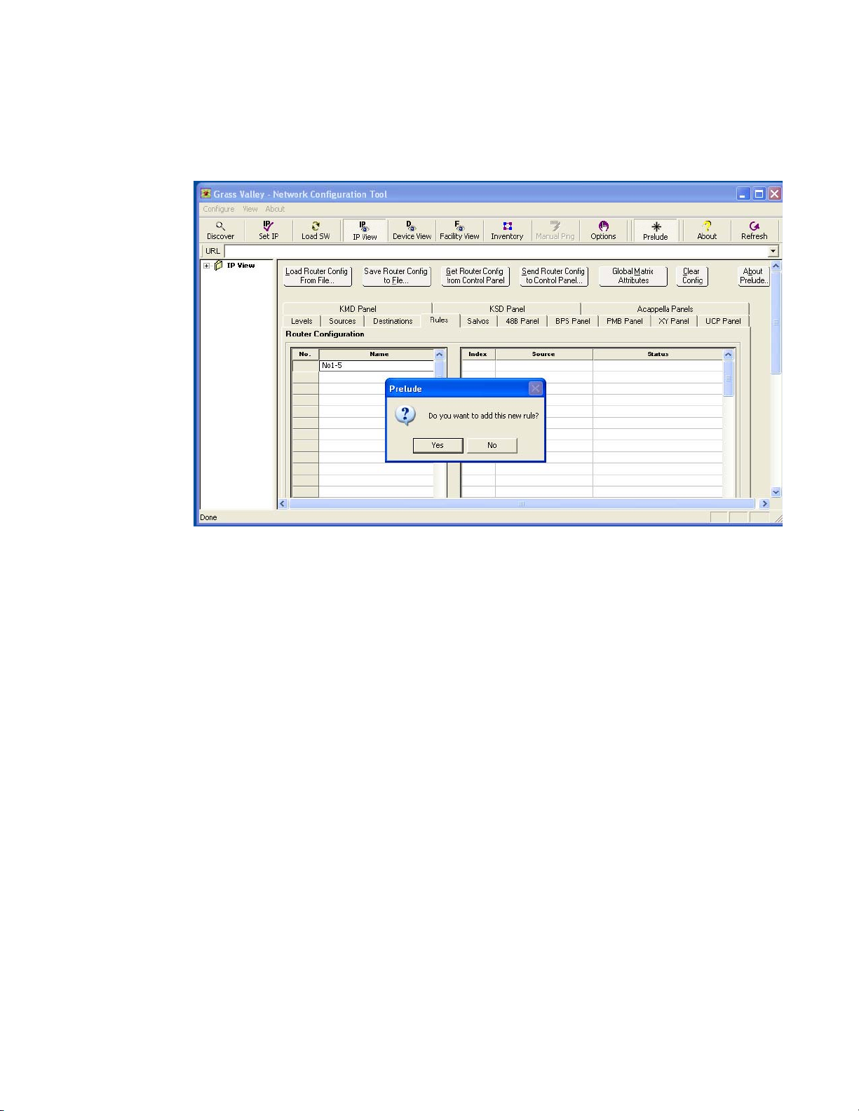
Source Exclusion by Destination (Rules)
2. Type in a descriptive name for the Rule and click Yes to the dialog box
(Figure 46).
Figure 46. Rules Screen, New Rule
3. When an existing rule is chosen in the pane on the left, the pane on the
right lists all Sources and indicates their status. A newly created Rule
has all Sources Available.
Prelude — Instruction Manual 61
Page 62

Section 2 — Installation and Initial Setup
4. Select the Sources you wish to exclude, and then right click and choose
Inhibit from the pop up list (Figure 47 and Figure 48).
Figure 47. Rules Screen, All Sources Available
Figure 48. Rules Screen, Sources Inhibited
You can also use the Available All and Inhibit All selections to set all the
Sources to the same state.
62 Prelude — Instruction Manual
Page 63

Once a Rule has been created, it can then be assigned to one or more Destinations.
Assigning a Rule to a Destination
5. Go to the Destinations screen, select Rule cells for one or more
Destinations, the right click and choose the Assign Rule. A pop-up list
of available rules is displayed (Figure 49).
Figure 49. Destinations Screen, Rule List
Source Exclusion by Destination (Rules)
Prelude — Instruction Manual 63
Page 64

Section 2 — Installation and Initial Setup
6. Select a Rule from the pop-up list and click OK. The screen will report
the Rule assigned to those Destinations (Figure 50)
Figure 50. Destinations Screen, Rule List Displayed
Clicking OK when a Rule is not selected clears a previously assigned
rule.
A Rule can also be cleared from a Desti
Rule cell and selecting
button.
Clear, or by selecting it’s cell and typing the Delete
Save and Send Router Configuration File
The changes you have made to this router configuration will not take effect
until the file is sent to the Prelude panels.
7. Save the router configuration on the PC with the Save Router Config to File
button, to keep as a backup. You can re-name the file if you wish.
8. Send the router config file to all the Prelude panels with the Send Router
Config to Control Panels
The specified inhibited Sources now will be able to be r
tinations with restrictive R
button.
ules assigned.
nation by right clicking on its
outed to those Des-
64 Prelude — Instruction Manual
Page 65

Output Monitoring
Prelude supports Concerto output monitor control, which permits the
viewing of output signals. This feature is typically used for quality control
purposes. Selecting a Destination on a control panel configured for output
monitoring will route that Destination’s output (showing its current
Source) to an output monitor connector. This displayed signal will track
any Source changes that occur for the currently selected Destination.
Output Monitoring
The Concerto matrix needs to be prope
monitoring. Concerto systems support one output monitor per matrix.
Refer to the Concerto Instruction Manual for specific information about hardware installation and cabling.
Output monitoring is configured in Prelude by adding output monitors to
Concerto Levels,
control panel for output monitoring.
Add an Output Monitor
1. Go to the Prelude Levels screen, click on an Output Monitor cell, and type
in the number
monitor to the configuration (Figure 51).
Figure 51. Prelude Levels Screen, Output Monitors Added
rly installed and cabled for output
defining an output monitor, and then configuring a
1 for each level to be monitored. This adds an output
Note Output Monitor values entered for non-Concerto matrices will revert to 0.
Prelude — Instruction Manual 65
Page 66

Section 2 — Installation and Initial Setup
2. Go to the Destinations screen, right click on a Name cell and select Add
Monitor
Figure 52. Destinations Screen, Adding Output Monitor Destination
(Figure 52). Give the output monitor a name.
3. Select the Levels to be monitored by entering the number 1 into each
Level cell (Figure 53).
Figure 53. Output Monitor Levels Defined
66 Prelude — Instruction Manual
Page 67

Configure Output Monitoring on a Panel
With an output monitor defined, you can now configure a control panel
that supports this feature.
4. Select the tab of a Prelude control panel that supports output
monitoring. This example uses an XY panel.
5. Check the Monitor Control box on the lower right portion of the screen.
This activates the feature and activates the
6. Click on the Dst Monitor/Page button and select the Destination Monitor
defined above, and choose a default Destination (Figure 54). If you
want to use the control panel only for monitor
Monitor Only box will prevent that panel from initiating any Takes.
Figure 54. Prelude XY Panel Output Monitor Configuration
Output Monitoring
Dst Monitor/Page control.
ing, checking the
Note It is possible to assign an output monitor to more than one panel. In this case,
the last monitor Take from any assigned panel will be honored. There may be
no indication on the panel which Destination is actually being monitored. This
can obviously cause confusion if different operators are controlling the same
output monitoring simultaneously.
Prelude — Instruction Manual 67
Page 68

Section 2 — Installation and Initial Setup
Save and Send Router Configuration File
The changes you have made to this router configuration will not take effect
until the file is sent to the Prelude panels. Save and Send the configuration
file, as described on
page 64.
Prelude Native Protocol Server
Introduction
Prelude control panels can be configured to act as Native Protocol (NP)
servers. Doing so can give external entities access to a Prelude routing
system. Some external devices, like Under Monitor Displays and the Visual
Status Display application, can use this interface to receive and display
status information. Other external devices, like automation systems, can
use this interface to actually control Prelude system crosspoints.
Prelude panels by default are not configured for external access. This
feature is activated by specifying the external client device that will be per
mitted access (via its IP address or Serial port settings) to a panel’s NP
server. That external client will then be able to communicate with that
server and, through that panel, interact with the rest of the Prelude system.
Client configurations can be created and saved for reuse on different
panels. This permits easy redundancy configuration for external clients
that support this capability.
All Prelude system control panel models support up to four Ethernet NP
servers. The UCP control panel supports one Serial port NP server in addi
tion to the four Ethernet servers.
NP Client/Server Configuration Process
The NP client/server configuration process involves several steps.
1. An external device client configuration is created and saved. This
configuration has a name for the client and the communications
settings to be used (IP address or serial communications port).
2. The client configuration is assigned to a specific server on a specific
panel. If that panel will support multiple clients, additional clients are
created and assigned to other servers on that panel (up to five).
-
-
3. The single or collection of client/server assignments is saved for that
panel.
4. The panel configuration with these assignments is sent to the panel.
68 Prelude — Instruction Manual
Page 69

5. The external client device is configured to communicate with the server
on that panel (using the IP address or serial communications port).
The external device will now have access to the Prelude system.
NP Server Configuration Window
Clicking the NP Server Configuration button for a panel opens a configuration
status window. This window has four or five data columns, which shows
the client configuration associated with each server (Figure 55).
Figure 55. NP Server Configuration Window
Prelude Native Protocol Server
The data in this window is not editable. Right or double-clicking on a Client
Name
field displays a list of available functions for creating client configu-
Prelude — Instruction Manual 69
Page 70

Section 2 — Installation and Initial Setup
rations. If the client field was empty a New client configuration can be
created (Figure 56).
Figure 56. New Client Configuration Function
NP Client Configuration Window
When New is selected, a window will open with editable fields for that client
(Figure 57).
Figure 57. Individual Client Configuration Window
Selecting Load displays a list of previously defined client files, one of which
can be selected and loaded for use by that server.
If the client field was already named, you can r
field and
opens.
Edit the existing client configuration data in the window that
ight or double-click on the
70 Prelude — Instruction Manual
Page 71

Additional Parameter Settings
Besides the name of the client configuration and communications settings
(IP address or serial connection settings), additional parameters can be set
for the client.
Prelude Native Protocol Server
Refresh Rate
Debug Rx
Debug Tx
Salvo Lock
Protect Override
Retain Protects
When non-zero, indicates the number of seconds the
client can remain silent. If the client does not send any
command within this duration, the server will declare it
an inactive client, drop all Protects done by it, and disconnect the client.
If ON, the server logs every command received by this
client on the console. Leave OFF unless debugging.
If ON, the server will logs every response sent to this
client on the console. Leave OFF unless debugging.
When ON, prevents Salvo operation.
If ON, individual Take commands (NOT Salvos) issued
by a client will go through even if the Destination is Protected/locked by some other devi
turned ON only if absolutely necessary.
When ON, the Protects issued by a client are retained
even after the client disconnects. If the Destinations protected by this client need to be unprotected, either the
nt has to reconnect and issue unprotect commands
clie
or the user needs to unprotect the Destinations from the
control panel hosting the client. When OFF, all the Protects issued by this client are unprotected as soon as the
cli
ent disconnects.
ce. This flag should be
Query Only
Save button at the bottom of the client configuration window saves the
The
current client configuration under its Client Name. The
Prelude — Instruction Manual 71
If ON, Take, Protect, and Salvo commands from this
client are not executed. Only query commands will be
executed.
Cancel button exits
Page 72

Section 2 — Installation and Initial Setup
the window without saving the data. After either selection you are
returned to the NP Server configuration window (see Figure 58).
Figure 58. NP Server Configuration Window
Once client configurations have been created and associated with a panel’s
servers, clicking on the
saves those settings for the panel. The
without making any changes to the assignments.
The panel configuration will need to be sent to the panel before any
assigned clients will have access to that panel.
It is also possible to
clears that information from that server but retains that saved client configuration file for use with other servers on the s
Save button on the Server configuration window
Cancel button exits the window
Remove a client configuration from a server, which
ame or other panels.
72 Prelude — Instruction Manual
Page 73

Kayak Serial Control
Prelude version 3.0 and newer software supports Kayak digital production
switcher control. Kayak systems use RS-422 serial 9-pin communications
(not Ethernet), so a Prelude UCP control panel will be required.
• On the Prelude system, in the NP Server configuration window choose
the s
then send that configuration to the UCP panel.
Table 6. Prelude Kayak Serial Control Settings
Baud Rate 38400
Data Bits 8
Stop Bits 1
Parity None
Handshake None
• On the Kayak system, select and configure the serial port connected to
the Prelude UCP control panel, choose control type
(Prelude supports only one area), and configure the Kayak Aux buses
and inputs to operate with the desired Prelude router Destinations.
Refer to the separate Kayak Installation and Service Manual for specific
information.
Prelude Native Protocol Server
ettings shown in Tabl e 6, save the UCP panel configuration, and
rcl_, select area 1
Prelude — Instruction Manual 73
Page 74

Section 2 — Installation and Initial Setup
74 Prelude — Instruction Manual
Page 75

Configuration Reference
Introduction
The previous section described how to configure a Prelude system with
basic functionality. Additional controls are also available, which are briefly
described in this section.
Device Web Pages
Concerto frames have web pages available that can be used for system configuration directly with any web browser. These pages are also available
through NetConfig, since it is a web browser. However, these web pages
duplicate functions that are much easier to use from within the Prelude
control system. There is little need to use the web pages directly, but they
are available should you remove the Prelude PC from the network and do
not have the Prelude UI available. Refer to the separate Concerto Instruction
Manual for specific information about these web pages.
Section 3
Stand-alone Acappella systems running without the Prelude control
system employ a series of web pages for configuration and device status
reporting. These web pages are also available through NetConfig, but are
not needed for configuration if you are using the Prelude control system,
(except for Local Acappella panels). Refer to the separate Acappella Instruc
tion Manual for specific information about these web pages.
Prelude — Instruction Manual 75
-
Page 76

Section 3 — Configuration Reference
48B Control Panel
Figure 59. 48B Panel Button Attributes and Flags
48B Panel Attributes and Flags
The lower portion of the Control Panel configuration page contains several
Control Panel parameters, which are based on Encore functionality. Grayed
out attributes and flags are not available for use with this panel type.
Backlight Brightness
Specifies the backlight brightness of the panel buttons within a range from
0 to 9. Zero is darkest, 9 is brightest.
76 Prelude — Instruction Manual
Page 77

Low Tally Brightness
Specifies the brightness of the panel low tally display within a range from
0 to 9. Zero is darkest, 9 is brightest.
Button Blink Rate
Specifies the rate of blinking buttons. Default value is 10. 1 is very fast, 50
(max value) is extremely slow.
Default Dst/Dst Page
Selects the default Destination selected after a panel reset.
Default Tally Level
When several Levels are available for this configuration, this field is used
to choose which Level will display Tally.
Level Exclusions
48B Control Panel
Opens a configuration window (Figure 60) allowing the selection of levels
to exclude from control by that panel. At least
excluded. Exclusion sets can be saved for reuse.
Figure 60. Level Exclusions
one level must remain un-
Prelude — Instruction Manual 77
Page 78

Section 3 — Configuration Reference
Joystick Override
Opens a configuration window (Figure 61) to set up Joystick Override settings, including GPI Salvo Select,
Non Latching.
Figure 61. Joystick Override
GPI Source Select, and GPI Source Select
NP Server Configuration
Opens a window allowing configuration of Native Protocol servers for the
control panel (Figure 62).
Figure 62. NP Server Configuration Window
The NP Server Configuration window displays a column of information for
each of the available servers. The data in this window is not editable.
Right or double clicking on a
a menu of commands (
Selecting a function will open an individual client configuration window
that allows editing. See NP Client/Server Configuration Pr
specific instructions.
Client Name field for one of the servers displays
Load, New, Edit, Delete, Remove) used for configuration.
ocess on page 68 for
78 Prelude — Instruction Manual
Page 79

Auto Level Latching
The Auto Level Latching permits control of the breakaway state for a Destination after a Take.
• When the Auto Level Latching flag is checked (on), the current
enabled/disabled level states are retained and applied to subsequent
takes for the currently active Destination. Selecting a different Destina
tion cancels the breakaway.
• When the Auto Level Latching flag is off, all levels of the currently
active Destination are enabled after a Take or change of active Destina
tion, irrespective of the previous level enable states(s).
Auto Tally
The panel buttons will tally the first available level for each Destination.
Backlight
Enables/disables the backlight feature for the control panel buttons.
48B Control Panel
-
-
Dst Change Lock
Enables/disables Destination changes from the control panel.
Flashing LED Indication
The Protect button will flash when the panel is the owner of an applied
Lock-Protect. The Level Select buttons will flash if the Source connected on
the assigned Level is different than the Tally Level (a breakaway). Owned
Locks and Protects tallies will flash.
Force Unlock/Unprotect
Allows the control panel to forcibly remove a Lock or Protect regardless of
the point of control that initiated the Lock or Protect.
Hard Lock
Allows the control panel to prevent Destination changes by all control
points including the initiating panel. Only the initiating control panel, or a
panel with Override or Force capabilities, can remove a hard lock. The Pro
tect, Hard Lock and Soft lock flags are mutually exclusive. Locks and Protects are applied to all configured levels.
-
Hold Breakaway
When enabled, the panel will retain Level breakaway settings even when
new Destinations are selected. Note that if the user presets Levels and
Prelude — Instruction Manual 79
Page 80

Section 3 — Configuration Reference
selects a Destination that does not support any of the preset Levels, the user
must manually preset Levels to match the controllable Levels for the new
Destination. The Prelude system will not change the preset Levels automat
ically to match the Destinations controllable Levels.
Level Change Lock
Enables/disables level changes from the control panel.
Lock/Protect Override
Allows the control panel to temporarily override a Lock or Protect placed
by other panels.
Protect
Allows the control panel to assert exclusive control of Destinations.
Another panel will not be able to change the Source for that Destination
(unless that other panel has Override or Force capabilities). The Protect,
Hard Lock and Soft lock flags are mutually exclusive. Locks and Protects
are applied to all configured levels.
-
Soft Lock
Allows the control panel to prevent Destination changes by all control
points including the initiating panel. Any control panel configured with a
Lock or Protect button can remove a soft lock. The Protect, Hard Lock and
Soft lock flags are mutually exclusive, and apply to all configured levels.
80 Prelude — Instruction Manual
Page 81

BPS Control Panel
Figure 63. BPS Panel Button Attributes and Flags
BPS Control Panel
BPS Panel Attributes and Flags
The lower portion of the Control Panel configuration page contains several
Control Panel parameters, which are based on Encore functionality. Grayed
out attributes and flags are not available for use with this panel type.
The parameters available are identical to those
starting on page 76, except for the following:
Display Brightness
for the 48B panel, described
Controls the illumination level of the alphanumeric display. Range is 0-9.
Prelude — Instruction Manual 81
Page 82

Section 3 — Configuration Reference
PMB Control Panel
Figure 64. PMB Panel Button Attributes and Flags
PMB Panel Attributes and Flags
The lower portion of the Control Panel configuration page contains several
Control Panel parameters, which are based on Encore functionality. Grayed
out attributes and flags are not available for use with this panel type.
The parameters available are identical to th
starting on page 76, except for the following:
Display Brightness
ose for the 48B panel, described
Controls the illumination level of the alphanumeric display. Range is 0-9.
82 Prelude — Instruction Manual
Page 83

Keypad
PMB Control Panel
Click this field to open a Keypad set configuration window (Figure 65).
Figure 65. Keypad Set Configuration Window
Alt Keypad
Dst Pages
Click on a keypad button to type in different legend. The buttons at the
bottom allow loading and existing keypad set, and saving the window’s
keypad setting under the same or a different name.
The Prelude system creates default keypad sets when it is launched for the
first time.
Click this field to open, create, and/or save an alternate keypad set for this
configuration. The alternate keypad set is available when you press the
key (assigned to one of the configurable keys) of a panel.
Pages control what set of items will be shown at the same time on the multiple displays of a PMB panel. Each page contains up to eight items, and a
Shift
Prelude — Instruction Manual 83
Page 84

Section 3 — Configuration Reference
total of 32 pages are available. Clicking on this button opens a configuration window (Figure 66). Destination Page Sets can be saved for reuse.
Figure 66. Define Destination Page Set Panel
Svo Pages
• Right click on a Load cell to insert a new row, delete a row, or load a previously saved page.
• Click on a
• Right click on a Destination page cell
using the same procedures used to define Destinations and Sources.
Salvo pages control what set of salvos will be shown at the same time on
the multiple displays of a PMB panel. Refer to Dst Pages on
Dst Page cell to name that individual page.
to enter the desired Destination,
page 83.
84 Prelude — Instruction Manual
Page 85

Dst Exclusion
Opens a dialog box (Figure 67) allowing the selection of Destinations to
exclude from control by that panel. No Destinations are excluded by
fault. Checking an item excludes it. Exclusion sets can be saved for reuse.
de
Figure 67. Destination Exclusion Panel
PMB Control Panel
Svo Exclusion
Opens a dialog box similar to Figure 67 allowing the selection of salvos to
exclude from access by that panel.
are excluded by default. Exclusion sets can be saved for reuse.
Alpha Sort RCE Names
When enabled gives the control panel the ability to scroll through a presorted alphanumeric Source and Destination name set.
Dst Mode Time-in
Checking the Dst Mode Time In box in the middle column activates the data
field of the same name on the left. This data field can be used to set the
length of time in seconds (from 1 to 1200) of no button activity before the
panel will automatically return to Destination Mode.
Mode Time In
Existing time settings are maintained in the disabled field, however.
are mutually exclusive. Enabling one disables the other.
Hold Preset
Checked items are excluded. All salvos
Dst Mode Time In and Src
When enabled, panels hold presets for additional Takes. If not enabled,
Source presets are cleared after each Take.
Prelude — Instruction Manual 85
Page 86

Section 3 — Configuration Reference
Keypad Dst Mode
When enabled makes the alternate keypad set the primary keypad set
whenever the panel enters Destination mode. This is useful for users who
prefer to separate the keypad prefix/suffix name sets according to Destina
tion or Source name lookups. This prevents the user from having to press
the Shift button when in Destination mode to access the alternate keypad
set. When in Destination mode and this flag is enabled, the Shift key will
work in reverse (toggles from alternate to primary keypad set).
Keypad Search Filter
When enabled, the panel will only search for exact keypad entered prefix/
suffix name matches. When disabled the prev/next buttons will display
either the next alpha sorted name in the list (if the Alpha Sort RCE Names
flag is enabled) or the next index sorted name. This allows users to quickly
access name sets in large routing systems.
Preset Swap
-
This parameter affects control panels operating in Source mode only. When
enabled, the Source connected to a Destination will automatically become
the preset Source after that Destination takes to a new Source. This allows
for a quick undo by pressing the Take button again.
Src Mode Time-in
Checking the Src Mode Time In box in the right column activates the data field
of the same name on the left. This data field can be used to set the length of
time in seconds (from 1 to 1200) of no button activity before the panel will
automatically return to Source Mode.
are mutually exclusive. Enabling one disables the other. Existing time set
tings are maintained in the disabled field, however.
Shift Latching
When disabled the Shift button operation to access the alternate keypad set
will be a temporary operation until a keypad button is pressed. After a
keypad button is pressed the Shift button will revert to the disabled condi
tion and the primary keypad set will again be enabled for the next keypad
button operation. This is useful for customers with very large name sets
who use common suffix sets like numbers.
Src Mode Time In and Dst Mode Time In
-
-
86 Prelude — Instruction Manual
Page 87

XY Control Panel
Figure 68. XY Panel Button Attributes and Flags
XY Control Panel
XY Panel Attributes and Flags
The lower portion of the Control Panel configuration page contains several
Control Panel parameters, which are based on Encore functionality. Grayed
out attributes and flags are not available for use with this panel type.
The parameters available are identical
described starting on page 82, except the XY panel does not have Dst Pages
or Salvo Pages.
to those for the PMB panel,
Prelude — Instruction Manual 87
Page 88

Section 3 — Configuration Reference
Acappella Remote Panels
Note Only Acappella Remote panels can be configured using Prelude. Acappella
control panels built into Acappella matrix frames are configured with the web
page for that Acappella matrix frame.
Figure 69. Acappella Panel Button Attributes and Flags
Acappella Remote Panel Types
If your Prelude system has different types of Acappella remote panels (8x1,
16x16, etc,) they will all appear on the
You should select only panel(s) that match the configuration type you have
created before you send the configuration to the panel(s). An Acappella
remote panel will operate with a mis-matched configuration, but buttons
not present on the panel will obviously not be usable.
Send Panel Config to Control Panel list.
88 Prelude — Instruction Manual
Page 89

Acappella Panel Attributes and Flags
The lower portion of the Control Panel configuration page contains several
Control Panel parameters, which are based on Encore functionality. Grayed
out attributes and flags are not available for use with this panel type.
Universal Control Panel (ENC-UCP)
The parameters available are identical to those
starting on page 76, except Acappella remote panels do not have Joystick
Override.
Universal Control Panel (ENC-UCP)
Figure 70. ENC-UCP Panel Button Attributes and Flags
for the 48B panel, described
Prelude — Instruction Manual 89
Page 90

Section 3 — Configuration Reference
ENC-UPC Attributes and Flags
The lower portion of the Control Panel configuration page contains several
Control Panel parameters, which are based on Encore functionality. Grayed
out attributes and flags are not available for use with this panel type.
The parameters available are identical to those for
starting on page 87, except the buttons are relocate
factor and the NP Server feature s
NP Server Configuration
Opens a window allowing configuration of Native Protocol servers for the
control panel. The UCP panel supports one serial server, in addition to four
Ethernet servers (Figure 71). The data in this window is not edi
NP Client/Server Configuration Process on pa
Figure 71. NP Server Configuration Window, UCP
the XY panel, described
d into the half/rack form
upports serial communications.
table. See
ge 68 for specific instructions.
90 Prelude — Instruction Manual
Page 91

KMD
KMD
KMD (Kalypso Multi-Destination) panels were originally developed for
Grass Valley Kalypso switcher systems, for use as remote aux panels.
Installing Prelude software into these panels converts them for use with
Prelude systems.
Figure 72. KMD Panel Button Attributes and Flags
KMD Panel Attributes and Flags
The lower portion of the Control Panel configuration page contains several
Control Panel parameters, which are based on Encore functionality. Grayed
out attributes and flags are not available for use with this panel type.
The parameters available are identical to those for the
starting on page 81.
Prelude — Instruction Manual 91
BPS panel, described
Page 92
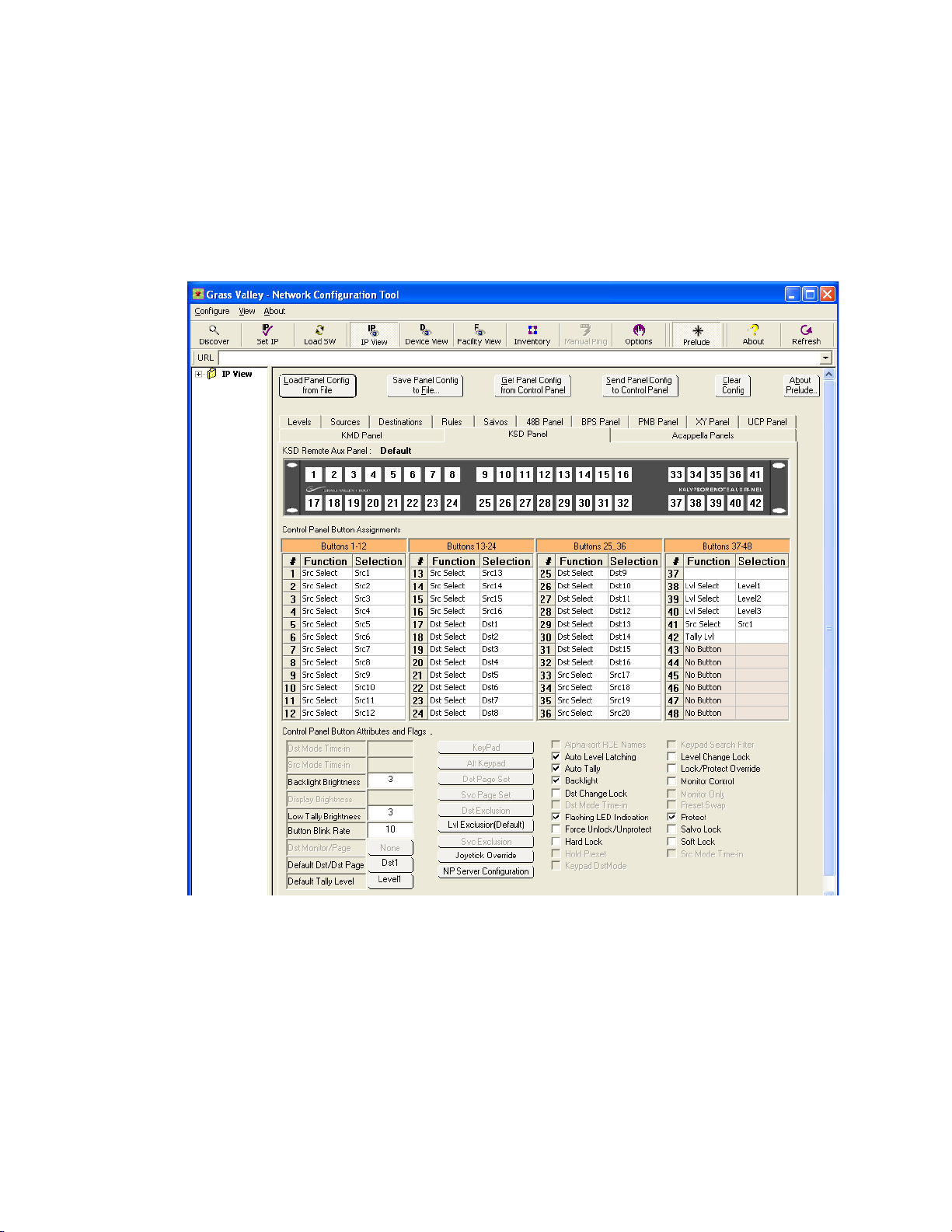
Section 3 — Configuration Reference
KSD
KSD (Kalypso Single Destination) panels were originally developed for
Grass Valley Kalypso switcher systems, for use as remote aux panels.
Installing Prelude software into these panels converts them for use with
Prelude systems.
Figure 73. KSD Panel Button Attributes and Flags
KSD Panel Attributes and Flags
The lower portion of the Control Panel configuration page contains several
Control Panel parameters, which are based on Encore functionality. Grayed
out attributes and flags are not available for use with this panel type.
The parameters available are identical to th
starting on page 76.
92 Prelude — Instruction Manual
ose for the 48B panel, described
Page 93

Soft Panels
Soft Panels
Prelude systems support Soft Panels, which are software versions of
various models of hardware control panel. Soft Panel instances are config
ured the same as their hardware equivalents, using the Prelude user interface available through NetConfig. Soft Panels is an optional application
that runs on a PC, and is licensed for use on that PC.
The Soft Panels application must first connect before it can be detected by
NetConfig. Once NetConfig sees the Soft Panel, it must be sent a router con
figuration so it knows what Levels, Sources, and Destinations exist. Each
individual Soft Panel instance (version of hardware control panel) must
also receive a panel configuration, which specifies the capabilities of that
software control panel.
See the separate Soft Panels Instruction Manual for specific information.
-
-
Prelude — Instruction Manual 93
Page 94

Section 3 — Configuration Reference
94 Prelude — Instruction Manual
Page 95

Appendix — Native Protocol
Prelude v3.0 and newer software support the Native Protocol commands
Ta bl e 7. Unsupported commands are indicated. Refer to the sep-
T – Query Software version
F – Query configuration Flags
f – Clear configuration flags
D – Clear flags set by QD command.
P – Client configuration parameters
E – Positive response setting
d – Query client name
“” – No parameter, refresh
D – Destination names
L – Level names
V – Salvo names
T – Tie Lines
IS - Source names with Source indices
ID - Destination names with Destination indices
A - Area names
IA - Area Names with area indices
shown in
arate Routing Products Protocols Manual for specific information.
Table 7. Prelude Native Protocol Command Support
Command Notes
AS – Machine Assign NOT SUPPORTED BY PRELUDE
BK - Background Activities N – Query system name
CH – Request Chop. NOT SUPPORTED BY PRELUDE
CT – Request Clear Destination Tielines NOT SUPPORTED BY PRELUDE
DA – Machine De-Assign NOT SUPPORTED BY PRELUDE
PR – Protect
QC - Query Combined Destination Status
QD & Qd - Query Destination Status
QE - Query Error Definition
QI & Qi - Query Destination Status on a Specific Level by Index
QJ & Qj - Query Destination Status by Index, Response Type 1
QN - Query Names S – Source names
QT – Query Date and Time NOT SUPPORTED BY PRELUDE
QV – Query Salvo
ST – Request Set Date and Time, NOT SUPPORTED BY PRELUDE
TA – Take, Name
TD – Take, Single Source
Prelude — Instruction Manual 95
Page 96

Appendix — Native Protocol
Table 7. Prelude Native Protocol Command Support
Command Notes
TI – Take, Index with Level Index
TJ – Take, Index with Level Bitmap
TM – Take, Monitor
TS – Take, Salvo
UP – Request Unprotect
96 Prelude — Instruction Manual
Page 97

Index
Numerics
48B
Attributes and Flags 76
panel configuration example 45
salvo configuration 57
48B Panel button 45
A
Acappella
general description 14
local panel configuration 51
router configuration 43
stand alone configuration 75
Acappella Instruction Manual 9
Acappella panel
Attributes and Flags 88
mismatched types 88
salvo configuration 57
AES
Input Attributes 42
Alpha Sort RCE Names parameter 85
Alt Keypad parameter 83
Attributes and Flags 49
48B 76
Acappella panel 88
BPS 81
KMD panel 91
KSD panel 92
PMB 82
UCP panel 89
XY 87
Auto Level Latching parameter 79
Auto Tally parameter 79
B
backward compatibility 28
BPS
Attributes and Flags 81
salvo configuration 57
Broadcast Select 34
button
48B Panel 45
Clear Views and Re-discover 24
Discover 24
IP View 24
Load SW 24
Options 24
Save Panel Config to File 49
Set IP 24
Button Blink Rate parameter 77
C
Clear
Rule from Destination 64
Clear Views and Re-discover button 24
Concerto
redundant operation 20
router configuration 35
web page 75
Concerto Instruction Manual 9
configuration
NP Client 68
NP Server 68
panel 44
router 35
sample files 35
control panel
identification 26
control panel system web page 27
copy 40
creating salvos 55
Backlight Brightness parameter 76
Backlight parameter 79
backup
router config file 28
Prelude — Instruction Manual 97
D
database
export salvos 59
Page 98

Index
for salvos 54
import salvos 59
salvo 59
Debug Rx button 71
Debug Tx button 71
Default Dst/Dst Page parameter 77
default IP addresses 20
Default Tally Level parameter 77
Destination
defining 41
maximum supported 12
Destination Configuration screen 41
device
name 26
Digital Video
Output Attributes 42
Discover button 24
Display Brightness parameter 81, 82
documentation online 4
Dst Change Lock parameter 79
Dst Exclusion parameter 85
Dst Mode Time-in parameter 85
Dst Pages parameters 83
E
Encore
general description 14
Encore Installation and Service Manual 9
Ethernet 11
compatible subnet 25
default IP addresses 20
duplicate IP addresses 25
switch specifications 19
exclusion set
destination 85
salvo 58, 85
exclusion sets 49
export
salvo database 59
F
FAQ database 4
Flashing LED Indication parameter 79
Force Unlock/Unprotect parameter 79
frequently asked questions 4
G
Global Attributes 41
reference 41
global salvos 54
Grass Valley web site 4
H
Hard Lock
applies to all levels 13
Hard Lock parameter 79
Hold Breakaway parameter 79
Hold Preset parameter 85
I
identify control panel 26
import
salvo database 59
Increment Down 39
Input Attributes 41
installation procedure overview 15
IP address
compatible subnet 25
Concerto redundancy 20
default 20
labeling devices 26
resolving duplicates 25
IP View button 24
J
Joystick Override parameters 78
K
Kayak
serial control 73
Keypad Dst Mode parameter 86
Keypad parameter 83
Keypad Search Filter parameter 86
KMD panel
Attributes and Flags 91
98 Prelude — Instruction Manual
Page 99

Index
KSD panel
Attributes and Flags 92
L
label IP addresses 26
level
assignment 35
name 36
Level Change Lock parameter 80
Level Exclusions parameter 77
Levels Configuration screen 36
license key 32
limitations of Prelude System 13
Load SW button 24
Lock
applies to all levels 13
Lock/Protect Override parameter 80
Low Tally Brightness parameter 77
M
matrix
size 35
matrix number
automatic entry 37
rule for use 37
monitoring an output 65
N
naming devices 26
Native Protocol commands 95
Native Protocol Server 68
NetConfig
general description 23
installation 21
IP View 24
main screen description 23
NetConfig Instruction Manual 9
network configuration
default IP addresses 20
of PC 20
PC requirements 19
NP Client
parameter settings 71
remove configuration 72
NP Client configuration window 70
NP Client/Server configuration 68
NP Server 68
configuration window 78
save settings 72
serial 73
NP Server configuration window 69
UCP 90
O
online documentation 4
Options button 24
Output Attributes 41
output monitor 65
adding 65
configuring panel 67
same on multiple panels 67
P
panel config file
sending to panel 50
panel configuration
Acappella local panel 51
creating 44
example 48
save panel config file to PC 49
sending panel config file to panel 50
sending router config file to panels 44
panel configuration example
48B 45
Panel Configuration screen 45
panel conversion 51
panel identity 52
paste 41
PC
network configuration 20
requirements 19
supplied by customer 12
PMB
Attributes and Flags 82
salvo configuration 58
Prelude
device names 26
general description 11
Prelude — Instruction Manual 99
Page 100

Index
registration 31
software versions 28
system capabilities 12
system components 15
system limitations 13
unregistered limitations 31
Preset Swap parameter 86
Protect
applies to all levels 13
Protect Override button 71
Protect parameter 80
Q
Query Only button 71
R
redundancy
Concerto IP address 20
reference
Global Attributes 41
Refresh Rate button 71
registration
license key 32
limitations when not registered 31
of Prelude 31
procedure 31
Retain Protects button 71
router config file
backing up 28
backward compatibility 28
saving to PC 43
sending to panels 44
router configuration
Acappella 43
Concerto 35
creating 35
Destination definition 41
level assignment 35
same for all panels 44
save router config file to PC 43
Source definition 38
Routing Products Protocols Manual 9
Rule
assign to Destination 63
clearing from Destination 64
creating 60
Rules 60
Rules screen 60
S
salvo
availability on panel 54
background information 54
configuration screen 54
creation 55
database 59
database export 59
database file 54
database import 59
exclusion set 58
global use 54
maximum number of 54
maximum size of 54
panel configuration 57
relation to router config 54
salvo configuration
48B 57
Acappella 57
BPS 57
PMB 58
XY 58
Salvo Editor Instruction Manual 9
Salvo Lock button 71
sample config files 35
Save Panel Config to File button 49
serial control
Kayak 73
Set Function 46
Set IP button 24
Set Selection 47
Shift Latching parameter 86
Soft Lock
applies to all levels 13
Soft Lock parameter 80
Soft Panels
operation with Prelude 93
Soft Panels Instruction Manual 9
software
installation 30
software download from web 4
100 Prelude — Instruction Manual
 Loading...