

Page 1

Installation and Operation
Profile
PLS 200 Library
Printed in USA or United Kingdom
Tektronix, Inc.
PO Box 1000
Wilsonville, OR 97070-1000 USA
1-800-547-8949 (USA and Canada)
1-503-682-7300
http://www.tek.com
Page 2

Copyright Copyright 1996 Tektronix, Inc. Wilsonville, Oregon.
Printed in the United States of America or the United Kingdom. All rights
reserved. This document may not be copied in whole or in part, or otherwise
reproduced except as specifically permitted under U.S. copyright law, without
the prior written consent of Tektronix, Inc., P.O. Box 1000, Wilsonville, Oregon
97070-1000.
Some portions are reprinted with permission:
Copyright 1994 – 1996 Exabyte Corporation. All rights reserved.
Disclaimer Tektronix, Inc., makes no representation or warranties with respect to the
contents of this document and specifically disclaims any implied warranties of
merchantability or fitness for any particular purpose. Further, Tektronix, Inc.
reserves the right to revise this publication without obligation of Tektronix, Inc.
to notify any person or organization of such revision or changes.
Trademark Notices TEKTRONIX and TEK are registered trademarks of Tektronix, Inc. Profile is
a trademark of Tektronix, Inc.
EXABYTE, EXAPAK, EXB, FileSECURE, LANCourier, and NetSECURE
are registered trademarks of Exabyte Corporation. Eagle, EXA, EXAFacts,
EXAsoft, EXATAPE, and SCIMON are trademarks of Exabyte Corporation.
Other trade names used in this document are trademarks or registered
trademarks of the manufacturers or vendors of the associated products.
Revision Status
Rev Date Description
December 1996 Original Issue; Manual Part Number 070-9619-00
ii PLS200 Library Installation and Operation
Page 3

Contents
Welcome
About this Manual......................................................................................xvi
Related Documentation.............................................................................xvi
Conventions Used in this Manual......................................................... xvi
Tektronix Product Support........................................................................ xvii
United States and Canada .................................................................. xvii
Europe................................................................................................. xvii
Asia and South America...................................................................... xvii
World Wide.......................................................................................... xvii
About the PLS200....................................................................................xviii
Library Elements .......................................................................................xxi
Chapter 1 Installing the Hardware
Preparing for Installation ..............................................................................1
Unpack the Library ..................................................................................1
Check the Accessories............................................................................2
Protect the Library Against ESD..............................................................2
Prepare the Library..................................................................................3
Verify Your Profile Software Version.......................................................3
Installing the SCSI Adapter Into the VDR.....................................................3
Installing the Library Hardware.....................................................................7
Install the Library Into a Rack..................................................................8
Unlatch and Open the Door...................................................................14
Remove the Packing Foam...................................................................15
Move the CHM Out of the Way..............................................................16
Prepare and Install Cartridges...............................................................17
Install Cartridge Magazines...................................................................20
Install a Cleaning Cartridge...................................................................22
Close the Library Door...........................................................................23
Connect the SCSI Cables......................................................................23
Connect the Power Cord.......................................................................28
Power-on the Library.............................................................................28
SCSI Adapter Board Software Update..................................................30
PLS200 Library Installation and Operation iii
Page 4

Contents
Chapter 2 Configuring the Library
Main Screen...............................................................................................32
Displaying the Configuration Menu ............................................................32
Setting the SCSI IDs ..................................................................................34
Setting Other Configuration Options ..........................................................36
Setting Parity Checking.........................................................................36
Adjusting the Contrast...........................................................................37
Setting the Back Light............................................................................38
Setting the Library Date.........................................................................38
Setting the Library Time ........................................................................39
Checking the Serial Number..................................................................39
Checking the Tape Drive Model............................................................41
Chapter 3 Operating the Library
Using the Operator Panel...........................................................................43
Main Screen ..........................................................................................43
Error Codes...........................................................................................44
Main Menu.............................................................................................44
Operator Keys .......................................................................................46
Operating in Different Control Modes.........................................................46
SCSI Interface Mode.............................................................................47
LCD Interface Mode ..............................................................................47
25/9 Pin Serial Port Mode......................................................................47
Changing the Control Mode...................................................................48
Replacing Data Cartridge Magazines.........................................................49
Resetting the Library..................................................................................51
Reset Key..............................................................................................52
Power-on Reset.....................................................................................52
Chapter 4 Operating the Tape Drives
Monitoring the Tape Drive LEDs................................................................53
Displaying Information About Tape Drives.................................................54
Fields on Drive Status Screen...............................................................55
Additional Fields on Mammoth Drive Status Screen.............................56
Ejecting a Cartridge Manually ....................................................................57
Chapter 5 Maintaining the Library
Replacing Tape Drives or Drive Blanks......................................................59
Using Drive Blanks................................................................................59
Replacing Tape Drives..........................................................................60
Replacing the Fuse ....................................................................................63
Replacing the Air Filter...............................................................................65
Cleaning the Front Window........................................................................67
iv PLS200 Library Installation and Operation
Page 5

Chapter 6 Packing and Shipping the Library
Returning the Library for Service............................................................... 69
Shipping the Library...................................................................................69
Preparing the Library for Shipping........................................................70
Inserting the Packing Foam in the Library ............................................71
Removing the Library From the Rack...................................................73
Packing the Library in the Shipping Containers.................................... 77
Chapter 7 Performing Diagnostics
Using the LCD Diagnostics Menu..............................................................83
Summary of Diagnostic Tests............................................................... 84
Accessing the Diagnostics Menu.......................................................... 85
Specifying Element Indexes..................................................................85
Stopping Diagnostic Tests....................................................................85
Self Test................................................................................................86
Position to Element............................................................................... 86
Park.......................................................................................................87
Move Cartridge ..................................................................................... 87
Scan......................................................................................................88
Scan with Range...................................................................................89
Home Gripper ....................................................................................... 89
Home CHM...........................................................................................90
Cycle Pick/Place...................................................................................90
Cycle Gripper........................................................................................ 91
Cycle S Axis..........................................................................................92
Cycle L Axis..........................................................................................92
Cycle Drum...........................................................................................93
Cycle Solenoid...................................................................................... 93
Cycle E/E..............................................................................................94
Configuring the Serial Ports for Diagnostics.............................................. 95
Chapter 8 Using the Library Info Menu
Accessing the Library Info Menu ............................................................... 97
Using the SCSI Menu................................................................................98
SCSI Mode Parameters........................................................................ 98
SCSI Reservations..............................................................................100
SCSI Sense Data................................................................................102
Viewing Statistics.....................................................................................104
Viewing System Sensors......................................................................... 106
Viewing Command History ......................................................................108
Using the Inventory Menu........................................................................110
Bar Code Label Information................................................................ 110
Element Occupied Information............................................................112
Element Position Information.............................................................. 113
Contents
PLS200 Library Installation and Operation v
Page 6

Contents
Chapter 9 Troubleshooting
Problems With Installation........................................................................115
Problems With Tape Drive Operation.......................................................116
Problems With Library Operation.............................................................117
If You Cannot Resolve the Problem.........................................................117
Appendix A Specifications
Storage Capacity......................................................................................119
Operating Environment ............................................................................119
Power.......................................................................................................120
Power Cord Requirements.......................................................................120
SCSI Terminator Specifications ...............................................................120
SCSI Cable Specifications .......................................................................121
Appendix B LCD Error Codes
Appendix C Bar Code Label Specification
Materials for the Label..............................................................................131
Dimensions of the Label...........................................................................132
Bar Code Characters................................................................................133
Checksum Character...........................................................................134
Bar Code Element Widths...................................................................135
Quality......................................................................................................136
Spots and Voids ..................................................................................136
Edge Quality........................................................................................136
Reflectance and Contrast....................................................................136
Label Degradation after Exposure to Light..........................................137
Optional Features.....................................................................................137
Alphanumeric Characters....................................................................137
Background Color................................................................................138
Testing the Bar Code Labels....................................................................138
Index
vi PLS200 Library Installation and Operation
Page 7

Figures
Contents
Element indexes for PLS200...................................................................xxiii
1-1 Removing the top covers............................................................................. 4
1-2 Removing the circuit board hold-downs.......................................................5
1-3 Screw locations for board mounting bracket................................................6
1-4 Attaching the slide rails................................................................................9
1-5 Adjusting the distance between the front mounting brackets ....................10
1-6 Installing the library in a rack.....................................................................11
1-7 Attaching the screws to the sides of the library .........................................12
1-8 Securing the library in the rack..................................................................13
1-9 Opening the door....................................................................................... 14
1-10 Removing the packing foam from the library.............................................15
1-11 Moving the CHM to the bottom of the long axis.........................................16
1-12 Positioning a bar code label on a data cartridge........................................17
1-13 Setting the write-protect switch on a data cartridge...................................18
1-14 Installing data cartridges in the magazine .................................................19
1-15 Installing a cartridge magazine in the library .............................................21
1-16 Installing a cartridge in the fixed cartridge slot...........................................22
1-17 Installing the terminators and SCSI jumpers .............................................24
1-18 SCSI connections from the VDR to the PLS200 ....................................... 25
1-19 SCSI connections through the PDX103 to the PLS200............................26
1-20 SCSI connections through the PRS200 to the PLS200............................27
2-1 Operator panel...........................................................................................31
3-1 Library menu structure...............................................................................45
3-2 Opening the library door............................................................................49
3-3 Replacing a cartridge magazine................................................................50
4-1 Eject button................................................................................................57
5-1 Removing and installing a tape drive.........................................................61
5-2 Replacing the fuse..................................................................................... 63
5-3 Replacing the air filters..............................................................................65
5-4 Replacing the air filter inside the air filter grille..........................................66
PLS200 Library Installation and Operation vii
Page 8

Contents
6-1 Installing the packing foam in the library....................................................71
6-2 Adjusting the packing foam........................................................................72
6-3 Removing the screws from the front of the rack.........................................74
6-4 Removing the screws from the sides of the library.....................................75
6-5 Lifting the library from the rack...................................................................76
6-6 Placing the antistatic bag over the library...................................................77
6-7 Placing the cushioned packaging around the library..................................78
6-8 Placing the accessory box and top on the library.......................................79
6-9 Placing the carton over the library..............................................................80
6-10 Securing the banding material....................................................................81
C-1 Dimensions of the bar code label.............................................................132
C-2 Area for printing bar code characters.......................................................133
C-3 Element dimensions; spots and voids......................................................135
C-4 Area for printing alphanumeric characters ...............................................137
viii PLS200 Library Installation and Operation
Page 9

General Safety Summary
!
!
WARNING: The instructions in this manual are for use by
qualified service personnel only. To avoid personal injury,
do not perform any servicing unless you are qualified to do
so. Refer to all safety summaries before performing service.
Review the following safety precautions to avoid injury and
prevent damage to this product or any products connected to it.
While using this product, you may need to access other parts of
the system. Read the General Safety summary in other system
manuals for warnings and cautions related to operating the
system.
Injury Precautions
Use Proper Power
Cord
Ground the Product This product is grounded through the grounding conductor of the
Do Not Operate
Without Covers
To avoid fire hazard, use only the power cord specified for this
product.
power cord. To avoid electric shock, the grounding conductor
must be connected to earth ground. Before making connections
to the input or output terminals of the product, ensure that the
product is properly grounded.
To avoid electric shock or fire hazard, do not operate this product
with covers or panels removed.
Use Proper Fuse To avoid fire hazard, use only the fuse type and rating specified
for this product.
Do Not operate in
Wet/Damp
Conditions
Do Not Operate in an
Explosive
Atmosphere
To avoid electric shock, do not operate this product in wet or
damp conditions.
To avoid injury or fire hazard, do not operate this product in an
explosive atmosphere.
PLS200 Library Installation and Operation ix
Page 10

General Safety Summary
Avoid Exposed
Circuitry
To avoid injury, remove jewelry such as rings, watches, and
other metallic objects. Do not touch exposed connections and
components when power is present.
Product Damage Precautions
Use Proper Power
Source
Provide Proper
Ventilation
Do Not Operate With
Suspected Failures
Do not operate this product from a power source that applies
more than the voltage specified.
To prevent product overheating, provide proper ventilation.
If you suspect there is damage to this product, have it inspected
by qualified service personnel.
Safety Terms and Symbols
Terms in This
Manual
!
!
!
!
These terms may appear in this manual:
WARNING:Warning statements identify conditions or practices
that can result in personal injury or loss of life.
CAUTION: Caution statements identify conditions or practices
that can result in damage to the equipment or other property.
Terms on the
Product
x PLS200 Library Installation and Operation
These terms may appear on the product:
DANGER indicates a personal injury hazard immediately
accessible as one reads the marking.
WARNING indicates a personal injury hazard not immediately
accessible as you read the marking.
CAUTION indicates a hazard to property including the product.
Page 11
Safety Terms and Symbols
Symbols on the
Product
!
!
The following symbols may appear on the product:
DANGER high voltage
Protective ground (earth) terminal
ATTENTION – refer to manual
PLS200 Library Installation and Operation xi
Page 12

Service Safety Summary
!
!
Do Not Service
Alone
Disconnect Power To avoid electric shock, disconnect the main power by means
Use Care When
Servicing With
Power On
WARNING: These instructions are for use by qualified
service personnel only. To avoid personal injury, do not
perform any servicing unless you are qualified to do so.
Refer to all safety summaries before performing service.
Do not perform internal service or adjustment of this product
unless another person capable of rendering first aid and
resuscitation is present.
of the power cord or, if provided, the power switch.
Dangerous voltages or currents may exist in this product.
Disconnect power and remove battery (if applicable) before
removing protective panels, soldering, or replacing
components.
To avoid electric shock, do not touch exposed connections
xii PLS200 Library Installation and Operation
Page 13

Regulatory Information
EC Declaration of Conformity
Tektronix, Inc.
Video Networking Division
14180 SW Karl Braun Drive
P.O. Box 500
Beaverton, Oregon 97077-0001 U.S.A.
Tektronix, Inc., Video Networking Division, declares on 27 September, 1996, under our sole
responsibility, that the PLS200 Video video Archive system to which this declaration relates,
is in conformity with the following standard(s) or other normative document(s):
EMC Directive 89/336/EEC
EC EN55022 Limits and methods of measurement of radio interference
characteristics of Information Technology Equipment
EC 50082-1
1992
Electromagnetic compatibility generic immunity standard Part 1:
Residential, commercial, and light industry.
Environmental Phenomena Test Specification Basic Standard
Radio-Frequency
Electromagnetic Field
Electrostatic Discharge 8kV (charge Voltage) IEC801-2
Fast Transients common
mode on Signal lines
AC mains ports 1.0kV (peak)
Low Voltage Directive 73/23/EEC
EN60950 Safety of Information Technology Equipment including
Electrical Business Equipment (includes Appendix ZB)
27-500 MHz
3V/m (unmodulated)
0.5kV (peak)
5/50 Tr/Th ns
5kHz Rep. Frequency
5/50 Tr/Th ns
5kHz Rep. Frequency
IEC801-3
IEC801-4
xiii
Page 14

Regulatory Information
Certifications and Compliances
Canadian Certified
Power Cords
FCC Emission
Control
Canadian EMC
Notice of
Compliance
Canadian approval includes the products and power cords
appropriate for use in the North America power network. All
other power cords supplied are approved for the country of use.
This equipment has been tested and found to comply with the
limits for a Class A digital device, pursuant to Part 15 of the FCC
Rules. These limits are designed to provide reasonable protection
against harmful interference when the equipment is operated in a
commercial environment. This equipment generates, uses, and
can radiate radio frequency energy and, if not installed and used
in accordance with the instruction manual, may cause harmful
interference to radio communications. Operation of this
equipment in a residential area is likely to cause harmful
interference in which case the user will be required to correct the
interference at his own expense. Changes or modifications not
expressly approved by Tektronix can affect emission compliance
and could void the user’s authority to operate this equipment.
This digital apparatus does not exceed the Class A limits for
radio noise emissions from digital apparatus set out in the Radio
Interference Regulations of the Canadian Department of
Communications.
Le présent appareil numérique n’emet pas de bruits
radioélectriques dépassant les limites applicables aux appareils
numeriques de la classe A préscrites dans le Règlement sur le
brouillage radioélectrique édicte par le ministère des
Communications du Canada.
xiv
EN55022 Class A
Warning
For products that comply with Class A. In a domestic
environment this product may cause radio interference in which
case the user may be required to take adequate measures.
Page 15
Welcome
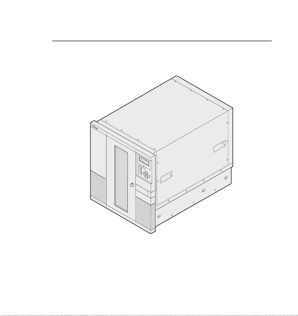
Congratulations on selecting the Tektronix PLS200 Library. Your new library
provides automated data storage, archiving, backup, and retrieval for Tektronix
Profile Video Disk Recorders (VDRs).
PLS 200
Profile
Help
Escape
Enter
Reset
9619-6
The library's robotic cartridge handling mechanism (CHM) responds to
commands from the VDR to move 8mm data cartridges between tape drives and
storage slots, while the tape drives read and write data. You can insert and
remove cartridges through the entry/exit port without opening the library door.
The PLS200 includes 80 data cartridge slots and four tape drives. The library is
connected to the VDR by three wide, differential SCSI buses.
PLS200 Library Installation and Operation xv
Page 16
Welcome
About this Manual
This manual provides the information you need to install, configure, operate,
maintain, and diagnose problems with the PLS200 Library and its enclosed
8mm tape drives. The operator information in this manual covers only the
operation of the library from the library’s operator panel. Information about the
operation of the library from the Profile Video Disk Recorder and its software
is available in the Profile System User Manual.
Related Documentation
The following documents are available from Tektronix:
• Profile System User Manual
• PLS200 Service Manual
• Profile Software Developer’s Kit
Conventions Used in this Manual
Enter
NOTE: Notes provide hints or suggestions about the topic or procedure being
xvi PLS200 Library Installation and Operation
Boxed characters indicate keys on the library's keypad.
discussed.
➤ Important Information next to the word “Important” will help you
complete a procedure or avoid extra steps.
The “attention” symbol and the word “CAUTION” precede information you
!
must know to avoid damaging the library or tape drives or losing data.
The “attention” symbol and the word “WARNING!” precede information
!
you must know to avoid personal injury.
Page 17

Tektronix Product Support
You can get technical assistance, check on the status of problems, or report new
problems by contacting our Product Support Group.
United States and Canada
Monday–Friday 5:30AM–5:00PM Pacific Time — (800) 547-8949
Europe
Monday–Friday 9:00AM–5:30PM
Austria 222-799-3535 Netherlands 010-495-4255
Belgium 02-714-3401 Norway 22-83-85-69
Denmark 3543-5259 Spain 91-564-4692
Finland 161-691-98559 Sweden 08-679-8419
Germany 069-935-25001 Switzerland 041-210-6009
Italy 44-1908-681-706 United Kingdom 01908-681-703
Luxembourg 400-848 Other 44-1908-681-703
Tektronix Product Support
Email: EuroProfile@tek.com
Asia and South America
Australia 61-2-888-7066 Korea 82-2-528-5299
Brazil 55-11-543-1911 Mexico 52-5-666-6333
Hong Kong 852-2585-6688 Singapore 65-356-3900
Japan 81-3-3448-3111 Taiwan 886-2-765-6362
World Wide
24-hour Emergency Hotline: (503) 685-2345
(Contract and warranty customers)
World Wide Web:http://www.tek.com/Profile/Support
FTP Site: ftp.tek.com (IP address: 134.62.48.21)
Email: ProfileSupport@tek.com
Users Group: profile-users@tek.com
PDR 100 1.4 Release Notes xvii
Page 18
Welcome
Reset
Enter
Escape
Help
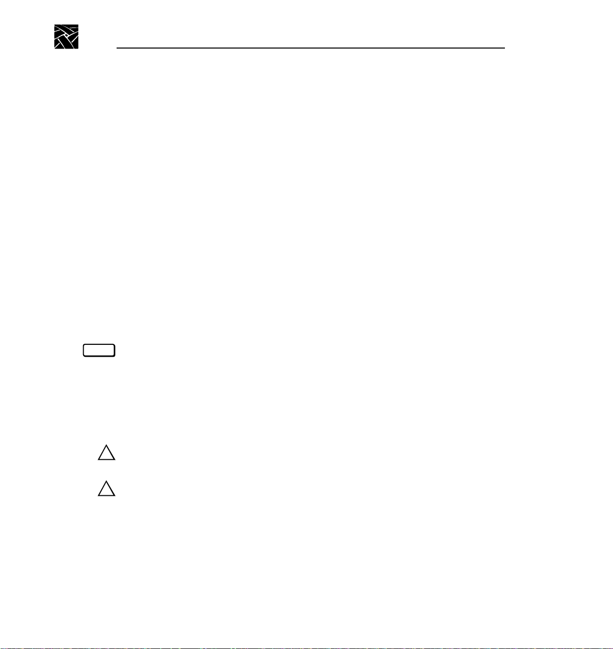
About the PLS200
The following illustrations and descriptions summarize the important library
features.
Operator Panel
The operator panel includes a four-line liquid crystal display (LCD) and a
keypad. You use the operator panel to configure the library and monitor
operations. If necessary, you can tilt the LCD for easier viewing.
Help
Escape
Enter
Reset
Entry/exit
port
xviii PDR 100 1.4 Release Notes
9619-7
Page 19
About the PLS200
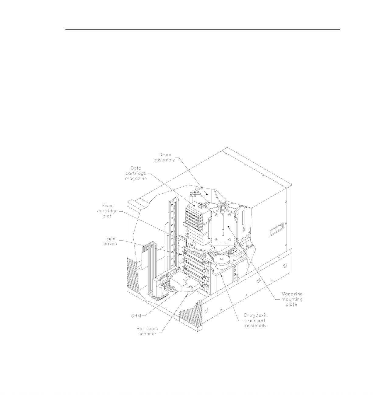
Entry/Exit Port and Transport Assembly
The entry/exit port allows you to insert or remove individual cartridges from the
library without opening the door. The entry/exit transport assembly moves the
transport arm to and from the entry/exit port to pick up cartridges.
Drum assembly
The drum assembly holds the data cartridge magazines and rotates 180 degrees
in either direction to position the magazines in front of the cartridge handling
mechanism (CHM).
PDR 100 1.4 Release Notes xix
Page 20
Welcome
Data cartridge magazines
Data cartridge magazines are the removable carriers for the 8mm data
cartridges. The magazines snap onto mounting plates on the library's rotating
drum assembly and allow easy removal and replacement of cartridges. Each
magazine has individual cartridge slots for 10 cartridges. The PLS200 contains
up to eight cartridge magazines.
Fixed cartridge slot
The fixed cartridge slot, located directly above the tape drives, provides a
storage location for a single cartridge. This slot is normally used to store an
8mm cleaning cartridge.
Tape drives
The PLS200 uses four Exabyte Mammoth 8mm half-height tape drives with a
wide, differential SCSI configuration.
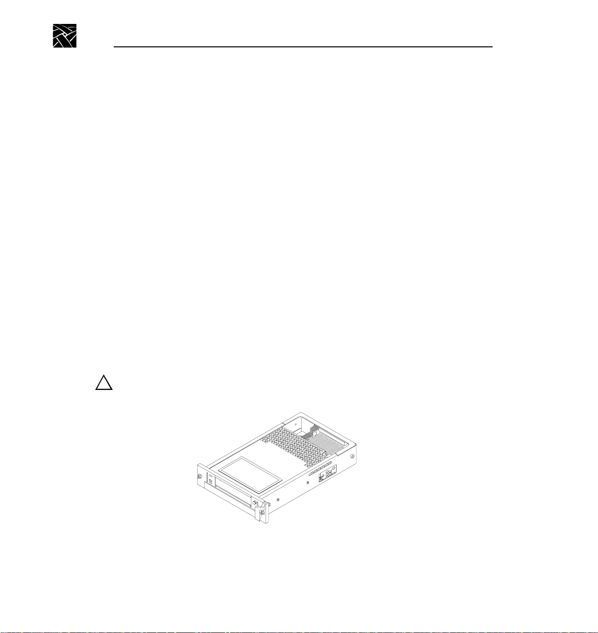
Drive carrier
When you purchase the library, each tape drive in the library is fitted inside a
drive carrier. The drive carrier allows you to slide the drive in and out of the
library if the tape drive needs repair.
CAUTION: To avoid possible damage to the tape drive, do not remove it from
!
the drive carrier.
xx PDR 100 1.4 Release Notes
Page 21

Library Elements
Drive blank (not shown)
Drive blanks are “empty” drive carriers with solid faceplates. If you plan to
operate the library with fewer than four tape drives, you must install drive
blanks in the empty drive positions. The drive blanks ensure correct air flow
through the library for cooling, compliance with EMI regulations, and in some
configurations, correct SCSI connection.
Cartridge handling mechanism (CHM)
The cartridge handling mechanism (CHM) moves cartridges between cartridge
slots, tape drives, and the entry/exit port.
Bar code scanner
The high-speed bar code scanner, mounted on the CHM, reads bar code labels
affixed to the cartridges to track individual cartridges. Cartridge label
information becomes part of the library's cartridge inventory stored in
nonvolatile RAM.
Serial ports (not shown)
Two serial ports (25-pin and 9-pin) at the back of the library allow an external
computer to communicate with the tape drives and the library across a serial
cable. By running a special diagnostic program, service personnel can perform
diagnostics, upgrade firmware, and test CHM motion.
SCSI connectors (not shown)
The library has ten SCSI connectors, accessible through the cabling bay on the
back.
Library Elements
The library contains four types of elements:
• The CHM is the medium transport element.
• The entry/exit port is the import/export element.
• The cartridge slots are the storage elements.
• The tape drives are the data transfer elements.
PDR 100 1.4 Release Notes xxi
Page 22
Welcome
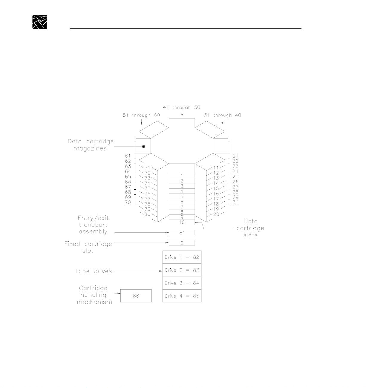
Each element has an element index, which is the number you must specify
when you use the entry/exit port. Element indexes must be the same as the
default element addresses used in SCSI commands.
The following figure shows the element indexes for the PLS200.
xxii PDR 100 1.4 Release Notes
Element indexes for PLS200
Page 23

Chapter
1
Installing the Hardware
This chapter describes how to install and set up the library hardware.
Preparing for Installation
Before installing the library, complete the preliminary steps listed in the table
below. Each step is described on the following pages.
✔
Step Description
1 Unpack the library.
2 Check the accessories.
3 Protect the library against ESD.
4 Obtain a fork lift or at least four people.
5 Verify your Profile software version.
Unpack the Library
Complete the unpacking steps printed on the box. Save the packing materials in
case you need to ship the library later.
PLS200 Library Installation and Operation 1
Page 24

Chapter 1 Installing the Hardware
Check the Accessories
Make certain you received the following accessories packed with the PLS200:
• Slide rails and mounting hardware
• Four power cords (North America, United Kingdom, Europe, Australia)
• BusLogic BT-757CD SCSI bus adapter board
• Three SCSI cables
• One SCSI terminator
• Four SCSI jumpers
• Eight Data Cartridge Magazines with covers
• Eighty data cartridges
• Two cleaning cartridges
• One spare drive blank (in addition to those installed)
• Bar code labels for the data cartridges (three sheets)
• PLS200 Operation and Installation Manual
• PLS200 Order Information Technical Data Sheet
Protect the Library Against ESD
If you remove the cover from the library, its internal components are
susceptible to damage from electrostatic discharge (ESD). To ensure that the
work area is as free from ESD as possible, place a grounded, static protection
mat on the work surface, and wear a static protection wrist band. If a mat and
wristband are unavailable, discharge static electricity from your body before
touching the inside of the library or the tape drives. (Touch a known grounded
surface, such as your computer's metal chassis.)
2 PLS200 Library Installation and Operation
Page 25

Prepare the Library
Prepare the Library
The slide rails and mounting hardware for rack-mounting the library are
shipped in the box with the library. The library weighs 152 pounds (69 kg) with
four tape drives installed. Before installing the library, make sure that your rack
has extension support legs and that you have at least four people or two people
and a small fork lift.
Verify Your Profile Software Version
The PLS200 requires Profile Software version 2.0 or higher, and WindowsNT
3.51 or higher.
Installing the SCSI Adapter Into the VDR
Before you install the PLS200 hardware, install the SCSI adapter board into the
Profile video disk recorder. The SCSI adapter board provides an EISA-to-SCSI
interface that allows the Media Manager or similar software on the VDR to
control the library’s cartridge handling mechanism. The procedures that follow
take you step-by-step through the recommended sequence for installation of the
SCSI adapter board.
WARNING: The VDR is too heavy for one person to remove from an
!
!
equipment rack. To avoid possible injury, get help when removing the VDR
from its rack.
WARNING: Before performing any installation or maintenance procedures,
!
be sure that:
• the rear-panel power switch is in the off position
• the power cord is disconnected from the video disk recorder and the outlet
PLS200 Library Installation and Operation 3
Page 26
Chapter 1 Installing the Hardware
1. Loosen the front panel retaining screws and pull the cabinet out until all three
slide sections latch.
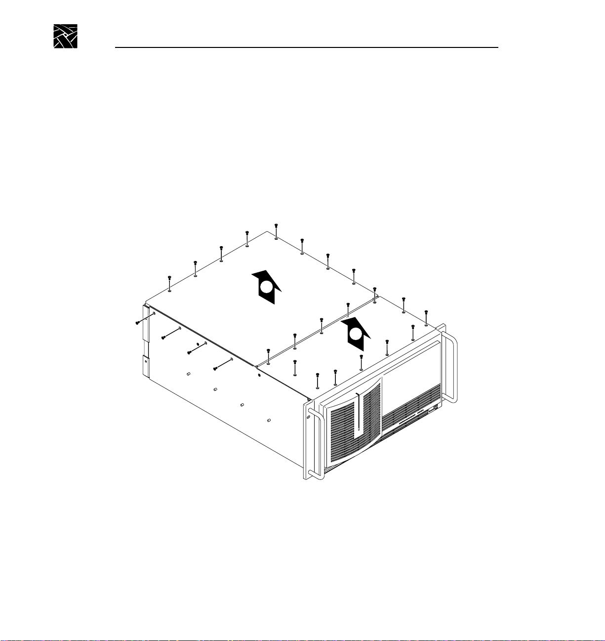
2. Remove the top covers in the order shown in Figure 1-1. The front cover
must be removed first since it overlaps the rear cover. Use a T-10 TORX
driver to remove the screws.
NOTE: Take care not to lose these cabinet screws. They are required to meet the EMI
specifications for the VDR.
2
1
Figure 1-1 Removing the top covers
4 PLS200 Library Installation and Operation
Page 27
Installing the SCSI Adapter Into the VDR
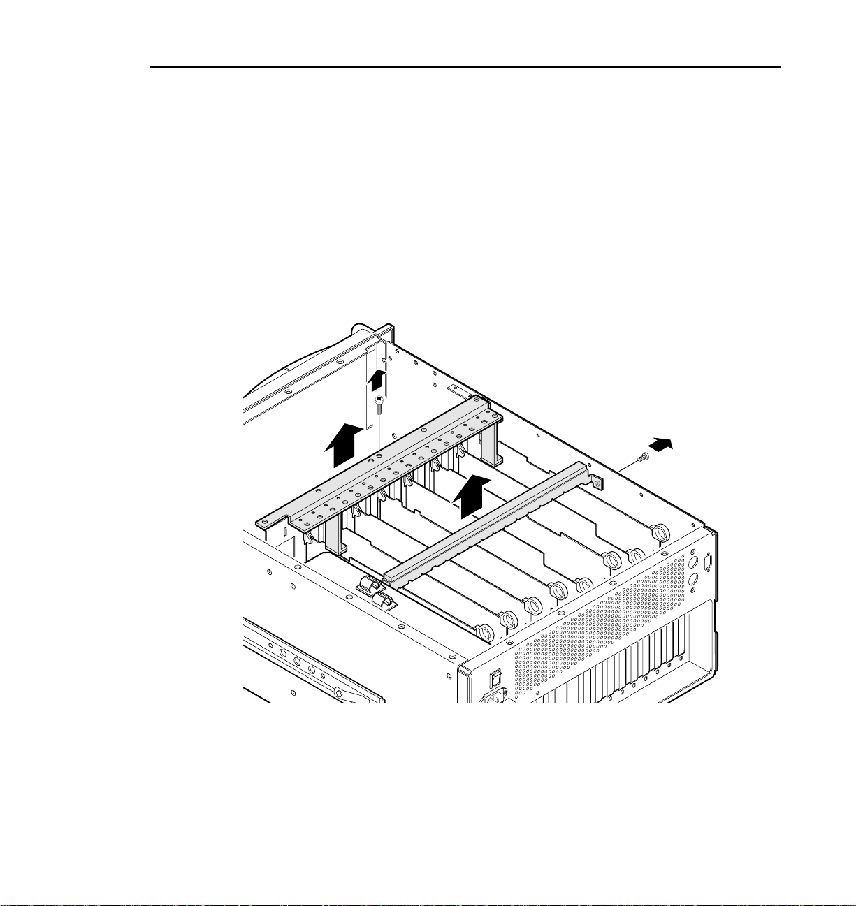
3. Remove the two circuit board hold-downs as shown in Figure 1-2. Both
hold-downs are held in place by T-10 TORX head screws, and must be
removed in order to install the SCSI adapter board.
➤ Important Be sure to remove the jumper as described in the following step.
If the jumper is left in place, the VDR will display an error when initializing
the SCSI adapter board.
4. Unpack the SCSI adapter board and remove the jumper from W1 on the
board. Refer to the manual packed with the board to locate the jumper.
Figure 1-2 Removing the circuit board hold-downs
PLS200 Library Installation and Operation 5
Page 28
Chapter 1 Installing the Hardware
5. Remove the blank cover plate from the J4 slot in the VDR rear panel.
6. Plug the SCSI adapter board into the J4 socket and press down till the board
is fully plugged into the socket.
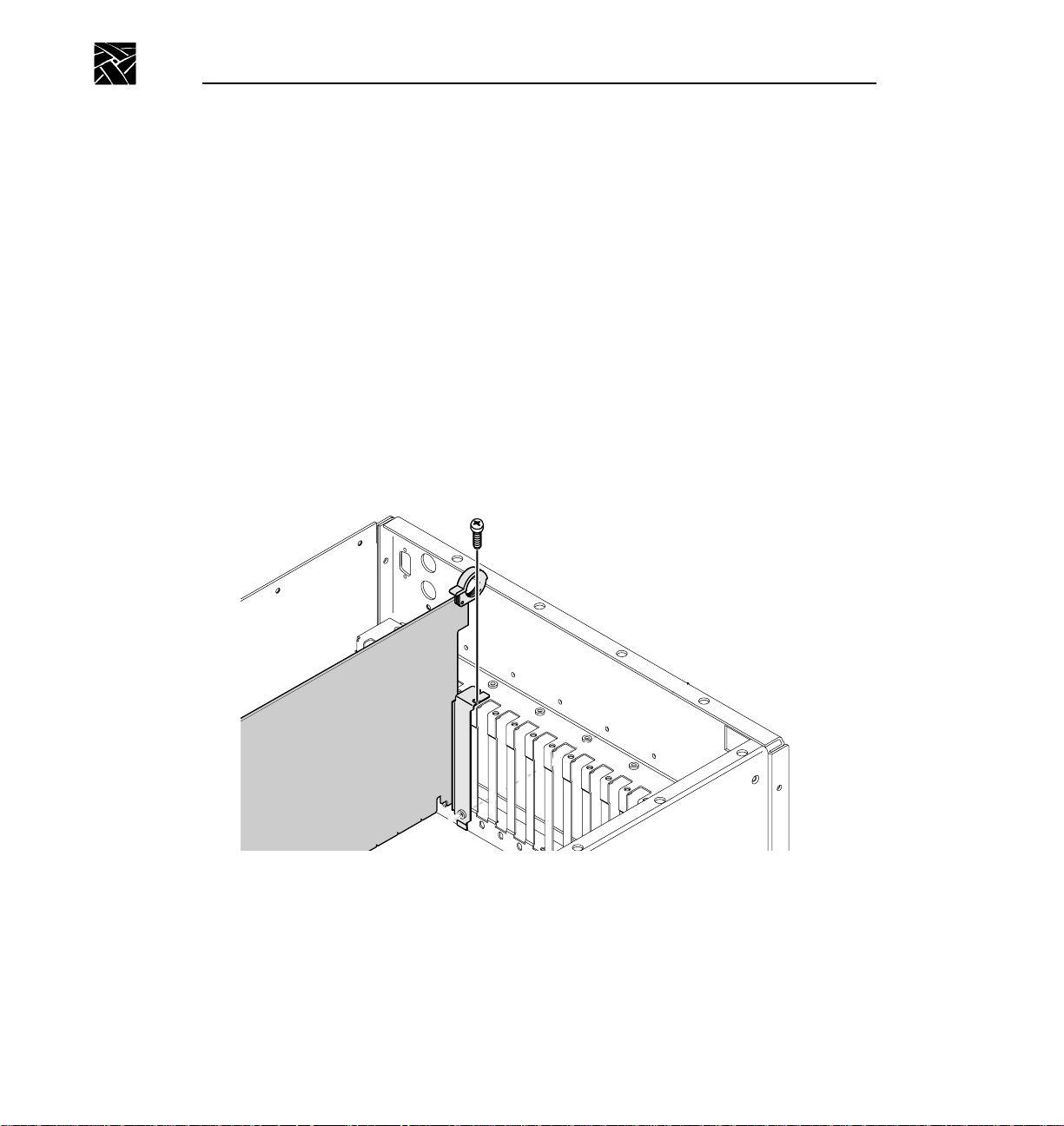
7. Install the mounting screw in the top of the bracket inside the cabinet (as
shown in Figure 1-3).
8. Re-install the hold-downs. Align each hold-down over the circuit boards and
replace the mounting screws.
9. Re-install the cabinet covers. Do not tighten any of the screws until all the
screws are started.
10. Install the VDR power cord, but do not turn on the VDR.
1
Figure 1-3 Screw locations for board mounting bracket
6 PLS200 Library Installation and Operation
2
Page 29
Installing the Library Hardware
Use the following table as a checklist for installing the library.
Installing the Library Hardware
✔
WARNING: Before performing any installation or maintenance procedures,
!
be sure that the library power switch is in the off position and that the power
Step Description
1 Install the library into a rack
2 Unlatch and open the door
3 Remove the packing foam
4 Move the CHM
5 Prepare and install cartridges in magazines
6 Install the magazines in the library
7 Install a cleaning cartridge
8 Close the library door
9 Connect the SCSI cables
10 Connect the power cord
11 Power on the library
12 Complete the SCSI adapter board software update
cord is disconnected from the library and the outlet.
PLS200 Library Installation and Operation 7
Page 30

Chapter 1 Installing the Hardware
Install the Library Into a Rack
Follow these instructions to install the library into a standard EIA 19-inch rack.
WARNING: The library weighs 137 – 167 pounds (62 – 76 kg). You need at
!
least 4 people, or 2 people and a small fork lift, to lift it.
Make sure you install the library in the lowest possible location in the rack
and that the rack is equipped with extension support legs.
Make sure you extend the support legs before installing the library in the rack
or when sliding it out of the rack.
Tools required
You need the following tools to install the library into a rack
• T-15 TORX screwdriver
• T-25 TORX screwdriver
8 PLS200 Library Installation and Operation
Page 31

Install the Library Into a Rack
Installing the Slide Rails
1. Identify the holes on the rack where you want to install the library. The
library will extend 1 to 2 inches (3 to 4 cm) below the slide rails.
2. If the rack does not have threaded holes, attach the eight clip nuts over the
holes (see Figure 1-4).
3. Using a T-25 TORX driver and eight 10-32 × 0.5 screws, attach, but do not
tighten, the slide rails to the rack (see Figure 1-4).
Figure 1-4 Attaching the slide rails
PLS200 Library Installation and Operation 9
Page 32

Chapter 1 Installing the Hardware
4. As shown in Figure 1-5, adjust the distance between the front mounting
brackets to 17 inches (44.8 cm).
5
-- 8
Figure 1-5 Adjusting the distance between the front mounting brackets
5. Tighten the screws.
6. Repeat steps 4 and 5 for the rear mounting brackets.
10 PLS200 Library Installation and Operation
Page 33

Install the Library Into a Rack
Installing the Library
1. Extend the extension support legs on the rack.
2. Slide the inside rails as far out of the rack as they will go (see Figure 1-6).
Figure 1-6 Installing the library in a rack
3. Remove the air filter grilles from the front of the library by lifting the outside
edges and pulling the grilles away from the library (see Figure 1-6).
4. Using four people, or two people and a fork lift, lift the library by the handles
and lower it onto the slide rails so the mounting tabs on each side of the
library fit into the slots in the rails (see Figure 1-6). Make sure all six
mounting tabs are fitted securely into the slots.
PLS200 Library Installation and Operation 11
Page 34

Chapter 1 Installing the Hardware
5. Press the spring clips and slide the library most of the way into the rack.
6. Install one 8-32 × button head screw into the screw hole on each rail, as
7
----- 16
shown in Figure 1-7.
Figure 1-7 Attaching the screws to the sides of the library
12 PLS200 Library Installation and Operation
Page 35

Install the Library Into a Rack
7. If the holes in the rack are not threaded, install a clip nut on each side of the
rack, as shown in Figure 1-8.
Figure 1-8 Securing the library in the rack
8. Slide the library completely into the rack. Use a T-25 TORX driver to insert
the two 10-32 × 1.0 pan head screws on the front panel, as shown in
Figure 1-8. These screws prevent the library from sliding out of the rack.
9. Replace the air filter grilles on each side of the front panel.
PLS200 Library Installation and Operation 13
Page 36

Chapter 1 Installing the Hardware
Reset
Enter
Escape
Unlatch and Open the Door
To open the door, turn the door latch handle one quarter turn to the right, as
shown in Figure 1-9. Pull open the door.
Help
Escape
Enter
Reset
Figure 1-9 Opening the door
14 PLS200 Library Installation and Operation
9619-8
Page 37

Remove the Packing Foam
Remove the packing foam from the library as shown in Figure 1-10.
1. Take out the center cross piece shown at arrow 1.
2. Move the vertical piece to the right as shown by arrow 2 to disengage it from
the CHM.
3. Bend the top of the vertical piece to the left and remove the top cross piece.
4. Pull the top of the vertical piece out of the door enough to allow removal of
the bottom cross piece, then take out the vertical piece.
Remove the Packing Foam
➌
➍
➊
Figure 1-10 Removing the packing foam from the library
➋
PLS200 Library Installation and Operation 15
Page 38

Chapter 1 Installing the Hardware
Move the CHM Out of the Way
Move the cartridge handling mechanism (CHM) so it is not blocking the
magazine mounting plates on the drum. To move the CHM, reach in through
the door and push against the base of the CHM, sliding it firmly to the bottom
of the long axis until it stops. See Figure 1-11.
➤ Important Do not touch the lens on the bar code scanner; smudges on the
lens can cause scanning errors.
Figure 1-11 Moving the CHM to the bottom of the long axis
16 PLS200 Library Installation and Operation
Page 39

Prepare and Install Cartridges
Prepare and Install Cartridges
Before installing data cartridges in the library, attach the bar code labels and set
the write-protect switches.
➤ Important Two types of EXATAPE™ 8mm Data Cartridges are available:
advanced metal evaporated (AME) and metal particle (MP). Use only the
AME tape cartridges in the PLS200. The tape drives in PLS200 cannot write
or read to the MP tape cartridges.
Attach Bar Code Labels
Position the label as shown in Figure 1-12, using the recessed area on the
cartridge for guidance. Make sure you orient the label correctly. For
information on how to prepare bar code labels, refer to Appendix C, Bar Code
Label Specification.
NOTE: Be sure to attach a bar code label to the cleaning cartridge as well as the data
cartridges.
➤ Important If you create your own bar code labels, be sure to follow the
specification precisely.
Figure 1-12 Positioning a bar code label on a data cartridge
CAUTION: If you remove a bar code label from a data cartridge without
!
replacing it, make sure to clean the label area thoroughly. Bar code labels
can leave adhesive on the label area, which may cause the data cartridge to
stick to the CHM.
PLS200 Library Installation and Operation 17
Page 40

Chapter 1 Installing the Hardware
Set the Write-protect Switches
Make sure the write-protect switch on each data cartridge is set appropriately
(see Figure 1-13). You can use a ball-point pen or similar instrument to move
the write-protect switch. If the write-protect switch window is red, the cartridge
is write-protected.
Figure 1-13 Setting the write-protect switch on a data cartridge
18 PLS200 Library Installation and Operation
Page 41

Prepare and Install Cartridges
Install Data Cartridges in the Magazines
The empty magazines are packed in the box of accessories shipped with the
PLS200.
1. Place the magazine on its feet with the single mounting guide toward the
right, as shown in Figure 1-14.
2. Position each cartridge so that the bar code label is on top and the
write-protect switch is toward the front (see Figure 1-14).
3. Insert the cartridge into the magazine slot.
NOTE: Very little force is needed to install a data cartridge. If it does not snap into
place easily or if it protrudes further than the magazine’s center rib, check
the orientation of the cartridge.
Figure 1-14 Installing data cartridges in the magazine
PLS200 Library Installation and Operation 19
Page 42

Chapter 1 Installing the Hardware
Install Cartridge Magazines
➤ Important Use only magazines designed for half-height Exabyte 8mm
libraries. Do not use Exabyte Data Cartridge Holders designed for
full-height Exabyte 8mm libraries.
The following instructions describe how to install cartridge magazines onto the
mounting plates on the drum.
CAUTION: Make sure the CHM and its cabling are safely out of the way
!
before installing cartridge magazines.
1. If necessary, manually rotate the drum to access the mounting plate where
you want to install the magazine.
2. On the magazine mounting plate, locate the roller on the top end of the plate.
3. Position the magazine over the mounting plate with the single mounting
guide toward the top, as shown in Figure 1-15.
4. Insert the bottom end of the magazine first, then snap the magazine into place
by pressing against the top.
20 PLS200 Library Installation and Operation
Page 43

Install Cartridge Magazines
Figure 1-15 Installing a cartridge magazine in the library
PLS200 Library Installation and Operation 21
Page 44

Chapter 1 Installing the Hardware
Install a Cleaning Cartridge
The following procedure describes how to manually install a cleaning cartridge
in the fixed cartridge slot. To replace this cartridge later, use the Export
Cartridge and Import Cartridge functions of the Media Manager in the Profile
Tool Box. Refer to the discussion of the Media Manager in the Profile System
User Manual.
CAUTION: Use Tektronix-approved cleaning cartridges only. Using cloth
!
swabs, cotton swabs, cleaning agents, or cleaning cartridges not approved by
Tektronix will void the tape drive warranty.
To install a cleaning cartridge in the fixed cartridge slot:
1. Position the cartridge so that the window showing the tape reels is toward the
top (see Figure 1-14).
➤ Important The cleaning cartridge must have a bar code label.
2. Insert the cartridge into the fixed cartridge slot until it snaps into place.
Figure 1-16 Installing a cartridge in the fixed cartridge slot
22 PLS200 Library Installation and Operation
Page 45

Close the Library Door
Close the library door and turn the door latch handle a quarter turn to the left.
Connect the SCSI Cables
The library is connected to the Profile system with three SCSI cables. One cable
controls the library and attaches to the SCSI adapter board. The other two
cables transfer data to and from the tape drives. These cables connect to the
SCSI A and SCSI B busses at the VDR Disk Recorder boards, the PDX103, or
PRS200 as shown in Figures 1-18, 1-19, and 1-20. All cables are fast wide,
differential with screw fasteners on both ends.
The SCSI connectors for the library and tape drives are accessible through the
cabling bay at the back of the library.
1. Remove the terminator plugs from the Master and Slave Disk Recorder
boards (or from the loop-through connectors on the PDX103 or PRS200).
Retain these plugs for use in the next step.
2. Install the SCSI jumpers and terminators on the PLS200 as shown in
Figure 1-17.
Close the Library Door
3. Connect the SCSI cables included with the PLS200. Refer to Figures 1-18,
1-19, and 1-20 as appropriate for your installation.
CAUTION: To avoid damaging the tape drives, make sure the power is off in
!
all devices connected to the SCSI bus when you connect the tape drives to the
SCSI bus.
PLS200 Library Installation and Operation 23
Page 46

Chapter 1 Installing the Hardware
PLS200
Library
Terminator
SCSI Jumper
Terminator
SCSI Jumper
Terminator
Drive 1
Drive 2
Drive 3
Drive 4
9619-4
Figure 1-17 Installing the terminators and SCSI jumpers
24 PLS200 Library Installation and Operation
Page 47

Connect the SCSI Cables
J15 J14 J4
PDR100
PLS200
SCSI Cable
Terminator
SCSI Jumper
9619-5
Figure 1-18 SCSI connections from the VDR to the PLS200
PLS200 Library Installation and Operation 25
Page 48

Chapter 1 Installing the Hardware
J15 J14 J4
PDR100
PDX103
PLS200
SCSI Cable
Terminator
Figure 1-19 SCSI connections through the PDX103 to the PLS200
26 PLS200 Library Installation and Operation
SCSI Jumper
9619-2
Page 49

Connect the SCSI Cables
PDR100
PRS200
PLS200
J15 J14
J4
Additional
PRS200
SCSI Cable
Terminator
SCSI Jumper
Figure 1-20 SCSI connections through the PRS200 to the PLS200
PLS200 Library Installation and Operation 27
9619-3
Page 50

Chapter 1 Installing the Hardware
Connect the Power Cord
➤ Important Tektronix ships the PLS200 with four power cords, each for use
in a different location. If none of the power cords are appropriate for your
location, you must supply a power cord with the proper plug that meets the
specifications listed in Appendix A, Specifications.
1. Make sure that the power switch on the back of the library is off (the 0 is
pressed).
2. Connect the female end of the power cord to the power connector on the back
of the library.
3. Plug the male end of the power cord into the power source.
NOTE: The library has autoranging voltage selection, so you do not need to change
the voltage setting.
Power-on the Library
1. Make certain the library's door is closed and latched.
2. Push the power switch on the back of the library to the on (I) position.
3. Turn on the PDX103 or PRS200 if one of them is attached to the SCSI bus.
4. Turn on the Profile video disk recorder.
NOTE: When you turn on the VDR, a warning will appear that slot 2 needs to be
configured. This is normal and is addressed when you complete the SCSI
adapter board software update at the end of this chapter.
5. Wait while the library performs its power-on self-test. During this time, the
following activities occur:
- The cooling fan begins to rotate.
- The LCD illuminates and displays the Main Screen.
- The tape drives perform their power-on self-tests.
- The library performs its power-on self-test.
28 PLS200 Library Installation and Operation
Page 51

Power-on the Library
Tape Drive Power-on Self-test
During its power-on self-test, each tape drive checks its operating conditions
and sends status information to the library.
Library Power-on Self-test
During its power-on self-test, the library:
• Engages the locking solenoid in the door.
• Moves the CHM to the home positions on the short and long axes.
• Moves the drum to the home position.
• Retracts the entry/exit port transport arm.
• Verifies the CHM's full range of motion by moving it to the top of the
long axis.
• Touches each cartridge to update the cartridge inventory.
• Moves to the home position on the long axis.
If Problems Occur...
If the library does not complete its power-on self-test and nothing is displayed
on the LCD, check the following:
• Is the power switch on? (Is the I pressed?)
• Is the power cord inserted correctly?
• Is the library door closed?
• Is the video disk recorder on?
If the library does not complete its power-on self-test and the LCD displays an
error code, see Appendix B, LCD Error Codes.
For more detailed troubleshooting information, see Chapter 9,
Troubleshooting.
PLS200 Library Installation and Operation 29
Page 52

Chapter 1 Installing the Hardware
SCSI Adapter Board Software Update
When you applied power to the Profile VDR (in the step on page 28), a warning
appeared that Slot 2 needed to be configured. The following procedure updates
software on the VDR and enables communication between the VDR and the
PLS200.
1. Double click the “Load DTI CMOS” icon to rewrite a new image into
CMOS. The console window indicates that the software has found the
BT-757CD (the SCSI adapter board) and has used the correct .cmo file.
2. Restart the VDR, and verify that the card in EISA slot two initializes
correctly. At this point the Buslogic BT-757CD SCSI card will be initialized
but can not be used by the PLS200 software until you install the driver for
the SCSI adapter board.
3. Install the driver for the SCSI adapter board.
a. Double click the “Windows NT Setup” icon in the Main group.
b. Pull down the “Options” menu and select “Add/Remove SCSI
Adapters...”, then click the “Add...” button.
c. Select the “Buslogic Standard SCSI Host Adaptor” driver from the list
and click the “Install” button. In the box that requests the location, type
“c:\i386” and click the “Continue” button.
d. Restart the Profile VDR, and log in as administrator (hold down the shift
key when the blue screen appears — factory-loaded password is triton).
4. Verify that Windows NT on the Profile VDR found the SCSI robot device.
a. Double click the “Windows NT Diagnostics” icon in the “Administrative
Tools” group.
b. Select “Registry Editor” found under the “Tools” menu.
c. In the “HKEY_LOCAL_MACHINE on Local Machine” window expand
the “HARDWARE,” then the “DEVICEMAP,” and then the “Scsi”
selections. Look for “SCSI” There should be a selection under “Scsi0” for
“ScsiPort0” that can be expanded to the “ScsiBus0” selection with
selections for the Initiator and each SCSI device on the bus. The PLS200
device will display as an EXABYTE EXB-480 under the “LogicalUnit0”
selection of the “Target” selection.
30 PLS200 Library Installation and Operation
Page 53

Chapter
2
Configuring the Library
After installing the library hardware, you need to set or check the library's
configuration options. Configuration steps include:
• Displaying the Configuration Menu
• Setting the SCSI IDs
• Setting or checking other configuration options as required
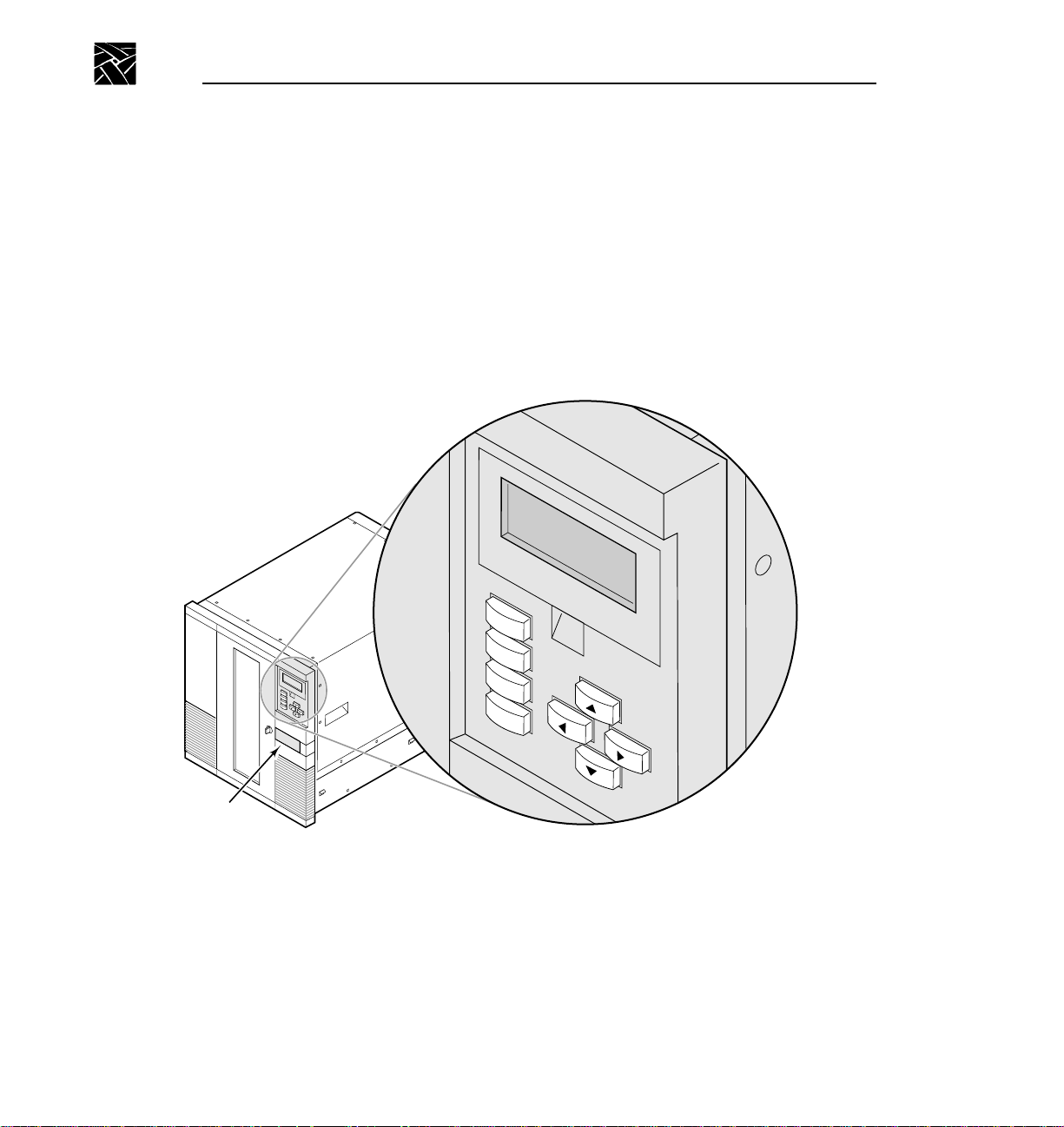
To change options, you will use the operator panel (LCD and keypad) on the
front of the library, as shown in Figure 2-1.
Figure 2-1 Operator panel
PLS200 Library Installation and Operation 31
Page 54

Chapter 2 Configuring the Library
Main Screen
The Main Screen appears when you apply power to the library. The first and
second lines on the Main Screen display the product name, version, and the
current time. The third and fourth lines display status information about the
library and tape drives.
P L S 2 0 0
V E R
S t a t u s : M o v e 1 - D
P i c k i n g F r o m S l o t 1
n . n n . n n h h : m m : s s
NOTE: The exact wording on your Main Screen may be different, and the
information that appears at power-up is overwritten as the PLS200 software
executes.
Displaying the Configuration Menu
To display the Configuration Menu:.
1. Access the Main Menu by pressing on the keypad. The Main Menu
is displayed:
M a i n S c r e e n
→
E x t e n d / R e t r a c t E / E
I n t e r f a c e M e n u
C o n f i g u r a t i o n M e n u
Escape
↓
32 PLS200 Library Installation and Operation
Page 55

Displaying the Configuration Menu
2. Press to scroll down to Configuration Menu. Press . The
Enter
Configuration Menu is displayed:
S e t S C S I I D s
→
S C S I P a r i t y O N
A d j u s t C o n t r a s t
B a c k L i g h t O N
↓
During library configuration, use the operator keys for the following functions:
Scrolls the screen arrow (→) up or down. The screen arrow points to
the current selection.
In some screens, moves the screen arrow left or right. On some menu
selections, toggles an option on or off.
Enter
Escape
Help
Selects the item next to the screen arrow or accepts a change.
Returns to the previous menu or screen, or cancels an operation
without saving changes.
Displays the Help screen. To exit Help, press .
Escape
PLS200 Library Installation and Operation 33
Page 56

Chapter 2 Configuring the Library
Setting the SCSI IDs
NOTE: The SCSI IDs shown are factory default settings. The default settings are the
correct IDs for use with the Profile system. Unless the SCSI IDs in the Profile
system have been altered, you should not need to change the library’s SCSI
ID settings. If one of the drive carrier slots contains a drive blank, the library
displays a B (for blank) instead of a SCSI ID.
Default SCSI IDs are assigned at the factory for the library and each tape drive.
Drive blanks are assigned B (for blank). This section describes how to view the
default settings and change them if necessary.
➤ Important The library and tape drives must each have a unique SCSI ID
within each SCSI bus. Because you have multiple SCSI buses, the library
does not check for duplicate SCSI IDs. It is your responsibility to make sure
you do not assign duplicate SCSI IDs within a SCSI bus.
To view or change SCSI IDs:
1. From the Configuration Menu, make sure the screen arrow is pointing to Set
SCSI IDs and press . The following screen appears, where Dn
indicates a tape drive and LIB indicates the library:
Enter
S C S I D 4 D 3 D 2 D 1 L I B
I D s : 0 2 0 1 0 2 0 1 0 5
↑
↓ →
2. To set the SCSI ID for the bottom tape drive (D4), press or until the
screen displays the SCSI ID you want. SCSI IDs for wide SCSI
configurations range from 0 to 15.
34 PLS200 Library Installation and Operation
Page 57

Setting the SCSI IDs
3. Press to move the up and down screen arrows to D3, as shown. Press
or until the screen displays the SCSI ID you want.
S C S I D 4 D 3 D 2 D 1 L I B
I D s : 0 2 0 1 0 2 0 1 0 5
↑
← ↓ →
NOTE: If any drive carrier slot contains a drive blank, the cursor will skip over the
SCSI ID field for that slot.
4. Continue this process until you have set the SCSI IDs for all tape drives and
the library.
5. When the SCSI IDs for all tape drives and the library are correct, press
Enter
to accept your choices. If you have changed one or more of the tape
drive IDs, the library displays the following screen:
P r e s s E N T E R t o r e s e t
t h e d r i v e ( s ) o r E S C
t o c a n c e l t h e S C S I
I D c h a n g e s .
6. Press . The library resets the tape drives that have changed IDs and
Enter
redisplays the Configuration Menu.
PLS200 Library Installation and Operation 35
Page 58

Chapter 2 Configuring the Library
Setting Other Configuration Options
After setting the SCSI IDs, you may need to set or check the following
configuration options before putting your library into operation:
• SCSI parity checking for the library
• LCD contrast
• LCD back light
• Library date
• Library time
• Library serial number
• Tape drive model
Setting Parity Checking
NOTE: The BusLogic BT-757CD SCSI adapter board used to connect the PLS200 to
the video disk recorder does not support parity checking for the library. As a
result, it makes no difference whether the setting for the library is ON or
OFF.
The SCSI Parity option allows you to enable parity checking for the library if
the SCSI adapter card connected to the library supports it. When the parity
option is enabled, the library checks all data coming across the SCSI bus for
parity. The setting you specify remains in effect across power cycles.
NOTE: Parity checking can also be enabled and disabled by application software
using a SCSI MODE SELECT command. The method last used to set parity
checking (LCD or SCSI command) has precedence.
36 PLS200 Library Installation and Operation
Page 59

Adjusting the Contrast
To change parity checking:
1. From the Configuration Menu, press to select SCSI Parity.
S e t S C S I I D s
→ S C S I P a r i t y O N
A d j u s t C o n t r a s t
B a c k L i g h t O N
2. Use and to toggle parity checking on and off.
Adjusting the Contrast
The Adjust Contrast option controls the brightness of the lettering on your
LCD. To adjust the contrast:
1. From the Configuration Menu, press to select Adjust Contrast and press
Enter
. The library displays the following screen:
L C D C o n t r a s t
L o w H i g h →
←
M i n . . . . . . . | . . . . . . M a x
2. Press and to change the contrast. Press to save your changes
and exit the Adjust Contrast screen.
←
↓
Enter
PLS200 Library Installation and Operation 37
Page 60

Chapter 2 Configuring the Library
Setting the Back Light
The Back Light option turns the LCD background on or off.
To change the back light:
1. From the Configuration Menu, press or to select Back Light.
S e t S C S I I D s
S e t P a r i t y O N
A d j u s t C o n t r a s t
B a c k L i g h t O N
→
2. Press and to toggle back lighting on and off.
Setting the Library Date
The Set Date option allows you to set the date for the library. The date appears
on the Command History screen (see page 108) and on diagnostic listings.
↓
To set the date:
1. From the Configuration Menu, press or to select Set Date and press
Enter
.
S e t M o n t h D a y Y e a r
D a t e : J a n 0 3 1 9 9 6
2. Press and to cycle through the selections under Month, Day, and
Year. Use and to move between the columns.
3. Press to save your changes and exit the Set Date screen.
38 PLS200 Library Installation and Operation
Enter
↑ →
Page 61

Setting the Library Time
Setting the Library Time
The Set Time option allows you to set the time that is shown on the library's
Main Screen and Command History screen (see page 108).
NOTE: The clock in the library is independent of outside clocks. It is not locked to
any external synchronization, and cannot be set or accessed by the Media
Manager on the Profile video disk recorder.
To set the time:
1. From the Configuration Menu, press to select Set Time and press
Enter
.
2. Use and to toggle through the selections under HH (hours), MM
(minutes), and SS (seconds). Use and to toggle between the columns.
S e t H H : M M : S S
T i m e : 2 0 : 2 2 : 0 9
↑ →
↓
3. Press to save your changes and exit the Set Time screen.
Enter
Checking the Serial Number
The serial number is entered into the library firmware at the factory. You can
read the serial number label on the back of the library or use the Set Serial
Number option. The serial number displayed on this screen appears on
diagnostic listings.
NOTE: If the serial number has never been entered, the number stored in memory is
99999999.
PLS200 Library Installation and Operation 39
Page 62

Chapter 2 Configuring the Library
To check the serial number:
1. From the Configuration Menu, press or to select Set Serial Number
and press .
2. If necessary, enter the serial number by pressing and to change each
digit. Press and to move from column to column.
Enter
S e t S e r i a l
N u m b e r : 9 9 9 9 9 9 9 9
↓ →
3. Press . The library displays the following screen:
4. Press to save your changes or press to cancel changes.
Enter
T h e s e r i a l n u m b e r i s
n n n n n n n n
E N T E R t o a c c e p t o r
E S C t o c a n c e l .
Enter
. P r e s s
Escape
40 PLS200 Library Installation and Operation
Page 63

Checking the Tape Drive Model
The tape drive model is entered into the library firmware at the factory. The
PLS200 uses only the Mammoth drives, and normally displays “ON” for the
Use Mammoth option.
To view the tape drive model:
1. From the Configuration Menu, press or to select Use Mammoth.
Checking the Tape Drive Model
S e t T i m e
S e t S e c u r i t y O N
S e t S e r i a l N u m b e r
U s e M a m m o t h O N
→
2. Press to return to the Configuration Menu.
Escape
↑
PLS200 Library Installation and Operation 41
Page 64

Chapter 2 Configuring the Library
42 PLS200 Library Installation and Operation
Page 65

Chapter
3
Operating the Library
This chapter describes library operations that you may occasionally need to
perform:
• Using the operator panel
• Operating the library in different control modes
• Resetting the library
Using the Operator Panel
The library includes a four-line LCD and keypad, called theoperator panel, that
allows you to control library operations. Using the operator panel, you can set
library options, check operating statistics, and diagnose errors. If desired, you
can tilt the LCD for easier viewing.
Main Screen
The Main Screen appears when you apply power to the library. The first and
second lines on the Main Screen display the product name, version, and the
current time. The third and fourth lines display status information about the
library and tape drives.
P L S 2 0 0
V E R
S t a t u s : M o v e 1 - D
P i c k i n g F r o m S l o t 1
NOTE: The exact wording on your Main Screen may be different, and the
information that appears at power-up is overwritten as the PLS200 software
executes.
n . n n . n n h h : m m : s s
PLS200 Library Installation and Operation 43
Page 66

Chapter 3 Operating the Library
Error Codes
If a library hardware error occurs, an error code appears on the third and fourth
lines of the Main Screen. The third line provides the error's numerical code; the
fourth line provides a brief explanation of the error. You must correct the error
before operation can continue; refer to Appendix B for a list of error codes and
corrective actions.
P L S 2 0 0
Main Menu
Use the Main Menu (shown below) to access LCD options and functions. To
access the Main Menu, press from the Main Screen.
• Select Main Screen to return to the Main Screen.
• Select Interface Menu to change the control mode (see page 48) and
configure the serial ports (see page 95).
•
Extend/Retract E/E can be used to control the entry/exit port. Not
recommended for adding tapes because it upsets the tape inventory database.
V E R
S t a t u s : E r r o r 1 1
S O U R C E E M P T Y
M a i n S c r e e n
→
E x t e n d / R e t r a c t E / E
I n t e r f a c e M e n u
C o n f i g u r a t i o n M e n u
n . n n . n n h h : m m : s s
Escape
↓
• Select Configuration Menu to set or change the library's configuration
options (see Chapter 2).
• Select Maintenance Menu to run demos (see page 95), or perform
diagnostic tests (see page 85).
44 PLS200 Library Installation and Operation
Page 67

Main Menu
• Select Library Info Menu to learn about library operations (see page 97)
and tape drive operations (see page 54).
The library menu structure is shown in Figure 3-1.
Main Menu Main Screen
Extend/Retract
E/E
Interface
Menu
Control Mode
Menu
LCD Interface
SCSI Interface
25/9 Pin Port
Config 25/9
Pin Menu*
Connect Drive 1
Connect Drive 2
Connect Drive 3
Connect Drive 4
Diag Console
Baud Rate 1200
Baud Rate 2400
Baud Rate 4800
Baud Rate 9600
Baud Rate 19200
*Your LCD may show
two entries: Config 25-Pin
Port and Config 9-Pin
Port.
Configuration
Menu
Set SCSI IDs
SCSI Parity
Adjust Contrast
Back Light
Set Date
Set Time
Set Security
Set Serial Number
Use Mammoth
Maintenance
Menu
Insert Cartridge
Remove Cartridge
Clean Drives
Menu
Clean Drive 1
Clean Drive 2
Clean Drive 3
Clean Drive 4
Demo Menu
Slot Demo
Drive Demo
Diagnostics
Menu
Self Test
Position to Element
Park
Move Cartridge
Scan
Scan w/Range
Home Gripper
Home CHM
Cycle Pick/Place
Cycle Gripper
Cycle S Axis
Cycle L Axis
Cycle Drum
Cycle Solenoid
Cycle E/E
Library
Info Menu
SCSI Menu
SCSI Mode Params
SCSI Reservations
SCSI Sense Data
Statistics
System Sensors
Command History
Drive Info Menu
Drive 1 Status
Drive 2 Status
Drive 3 Status
Drive 4 Status
Inventory Menu
Label Information
Occupied Info
Position Info
Figure 3-1 Library menu structure
PLS200 Library Installation and Operation 45
Page 68

Chapter 3 Operating the Library
Operator Keys
The keys on the operator panel perform the following functions:
Scrolls the screen arrow (→) up or down. The screen arrow points to
the current selection.
In some screens, moves the screen arrow left or right. On some menu
selections, toggles an option on or off.
Enter
Escape
Reset
Help
Selects the item next to the screen arrow or accepts a change.
Returns to the previous menu or screen, or cancels an operation
without saving changes.
Displays the Reset screen, which allows you to reset the library and the
tape drives.
Displays the Help screen. To exit Help, press .
Escape
Operating in Different Control Modes
The library's control mode determines which interface controls CHM motion.
In this control mode... The CHM is controlled by... Purpose
SCSI Interface Media Manager (or other similar
application software)
LCD Interface A user at the operator panel Diagnostics
25/9 Pin A user operating a console interface
to access library firmware across the
25- or 9-pin port
NOTE: Control mode settings remain in effect when library power is shut off.
Standard operating mode
Diagnostics
46 PLS200 Library Installation and Operation
Page 69

SCSI Interface Mode
SCSI Interface Mode
In SCSI Interface mode, application software such as Media Manager controls
the motion of the CHM by issuing SCSI commands across the SCSI bus
attached to the library. This is the normal operating mode for the PLS200.
NOTE: The library must be in SCSI Interface mode for the software to control the
motion of the CHM.
For detailed information about the SCSI commands supported by the PLS200
contact your Tektronix representative.
LCD Interface Mode
When the library is operating in LCD Interface mode, you can control the
motions of the CHM from the operator panel.
NOTE: You can use many operator panel features without changing to LCD
Interface mode. LCD Interface mode is required only when you want to
control the motions of the CHM from the operator panel.
25/9 Pin Serial Port Mode
When the library is operating in 25/9 Pin mode, you can control the motions of
the CHM from a remote console program connected to the library's 9-pin or
25-pin port.
NOTE: Use the 25/9 Pin mode to control CHM motion only. You do not need to
change the control mode to access a tape drive's serial port.
PLS200 Library Installation and Operation 47
Page 70

Chapter 3 Operating the Library
Changing the Control Mode
➤ Important When you change from SCSI Interface control mode to any
other mode, you cannot control CHM motion with Media Manager or other
similar software.
1. Make sure the library is in the ready state (that is, no hardware errors, door
closed, and no cartridge move operations occurring).
2. From the Main Menu, press to select Interface Menu.
3. From the Interface Menu, press to select Control Mode Menu and press
Enter
.
4. From the Control Mode Menu, press to select the control mode and press
Enter
. The current control mode is indicated with an asterisk (*). The
library changes from the current control mode and displays a screen similar
to the following:
A C T I V E I N T E R F A C E :
F rοm : S C S I
T o
:
S t a t u s : D O N E
5. Press to return to the Interface Menu, and again to return
Escape Escape
to the Main Menu.
48 PLS200 Library Installation and Operation
L C D
Page 71

Replacing Data Cartridge Magazines
Replacing Data Cartridge Magazines
To open the door and replace a data cartridge magazine:
1. Turn the door latch handle one quarter turn to the right, as shown in
Figure 3-2.
➤ Important Do not open the library door unless you need to remove and
replace cartridge magazines or perform a maintenance operation. It takes 2
to 5 minutes for the library to update the cartridge inventory after the door
is opened and closed.
Figure 3-2 Opening the library door
When you unlock the door:
- The library completes its current operation, moves the CHM to the home
position at the bottom of the long axis, rotates the drum assembly to the
home position, and turns off current to all motors.
- The interlock mechanism releases.
PLS200 Library Installation and Operation 49
Page 72

Chapter 3 Operating the Library
2. When the door's interlock mechanism releases, open the door.
CAUTION: Do not force the door open. The door's interlock mechanism may
!
be prevented from releasing by LCD security or by Media Manager (or other
similar software).
3. Make sure the CHM and its cabling are safely out of the way of the
magazines. If necessary, move the CHM to the bottom of the long axis by
pushing firmly against its base.
4. If necessary, manually rotate the drum assembly to access the cartridge
magazine you want to remove.
5. Grasp the cartridge magazine on either side, pull the upper end out first, and
remove it from the mounting plate (see Figure 3-3).
Figure 3-3 Replacing a cartridge magazine
50 PLS200 Library Installation and Operation
Page 73

6. Replace the magazine by positioning it over the mounting plate with the
single mounting guide toward the top.
7. Insert the bottom end of the magazine first, then snap the magazine into place
by pressing against the top.
8. Close the door and lock it by turning the key a quarter turn to the left. After
the door is closed:
- The library performs its power-on self-test.
- The library returns Unit Attention status to the Profile system.
- The software such as Media Manager may update its own cartridge
inventory.
Resetting the Library
CAUTION: Resetting the library disrupts operation of the Profile video disk
!
recorder to which the library is connected, requiring that the video disk
recorder be restarted. Avoid resetting the library while it is connected to the
video disk recorder.
Resetting the Library
If the library has encountered an error and is still not operating after you have
tried the corrective action for the error, you may need to reset the library. A
reset causes the library and the tape drives to perform their power-on self tests.
Unless configured otherwise, tape drives will rewind the tape after a reset, but
will not eject the data cartridge.
NOTE: If the library is performing a cartridge move operation when it is reset, it
completes the move operation before it performs the power-on self-test.
CAUTION: Before resetting the library, make sure the library or tape drives
!
are not communicating across the SCSI bus. Resetting the library and tape
drives may disrupt communications on the SCSI bus.
As described in this section, you can use any of the following methods to reset
the library and tape drives:
• Press the reset key on the operator panel
• Turn the library's power off and back on again
PLS200 Library Installation and Operation 51
Page 74

Chapter 3 Operating the Library
Reset Key
When you press , the following message appears:
Press to reset the library and tape drives, or press to cancel the
Enter
Reset
D o y o u r e a l l y w a n t
t o r e s e t ?
E N T E R : R e s e t n o w
E S C : C a n c e l
Escape
reset and return to the previous menu or screen.
Power-on Reset
CAUTION: Unless necessary for mechanical reasons, do not turn the power
!
off while there are cartridges in the tape drives or CHM.
Turn the library off, then on. A power-on reset also resets the tape drives.
NOTE: The library and tape drives can also be reset automatically by SCSI bus resets
or Bus Device Reset messages.
52 PLS200 Library Installation and Operation
Page 75

Chapter
4
Operating the Tape Drives
Once installed and configured, the Media Manager or similar software
automatically controls the tape drives as you perform store and retrieve
operations. Unless there is a problem with the tape drives, you should never
need to touch them. However, you may need to perform the following tasks,
which are described in this chapter:
• Monitoring the tape drive LEDs
• Displaying information about tape drives
• Ejecting a cartridge manually
NOTE: You cannot control the tape drives from the operator panel. However, you can
perform diagnostics on the tape drives across the 9-pin or 25-pin serial port.
Monitoring the Tape Drive LEDs
The tape drives use light-emitting diodes (LEDs) to indicate their operating
states. Normally, you do not need to monitor the LEDs when the tape drives are
installed in the library; however, basic tape drive LED states are described
below for your reference.
The following table shows basic LED states.
LED state Condition
All LEDs on The tape drive was reset or it is performing its power-on self-test.
Top LED on Cleaning required.
Top LED flashing Hardware error.
Middle LED on A tape is loaded, and the tape drive is ready to perform tape motion
activities.
Bottom LED flashing Tape motion. A fast flash indicates high-speed tape motion.
PLS200 Library Installation and Operation 53
Page 76

Chapter 4 Operating the Tape Drives
Displaying Information About Tape Drives
You can display information about your tape drives from the Drive Info Menu,
accessible under the Library Info Menu. The information screens are updated
whenever there is a change in drive status.
To display tape drive information:
1. From the Main Menu, press or to select the Library Info Menu and
press .
Enter
2. Press or to select the Drive Info Menu and . The library
Enter
displays the following screen:
D r i v e 1 S t a t u s
→
D r i v e 2 S t a t u s
D r i v e 3 S t a t u s
D r i v e 4 S t a t u s
↓
3. Press or to select the tape drive for which you want to display
information and press . For each installed tape drive, the library
Enter
displays a screen similar to the following:
D R I V E 1 S T A T U S :
T y p e M A M M O T H
P r e s e n t 1
A c c e s s i b l e 1
4. Press to return to the previous menus.
Escape
↓
54 PLS200 Library Installation and Operation
Page 77

Fields on Drive Status Screen
Drive Status:
Fields on Drive Status Screen
DRIVE N
STATUS
Type Identifies the tape drive model. This information is updated at power-up and after a reset.
Present Indicates whether a tape drive is installed in this slot:
Accessible Indicates the accessibility of the tape drive to the CHM:
Clean 0 – The tape drive is clean.
Warning Not currently used.
Occupied 0 – There is no cartridge loaded in the tape drive.
Identifies the tape drive, as follows:
DRIVE 1 – The top tape drive
DRIVE 2 – The second from top tape drive
DRIVE 3 – The third from top tape drive
DRIVE 4 – The bottom tape drive
Note: “8mm” for Type indicates one of the following conditions:
• No tape drive is present in this slot.
• A Mammoth tape drive is installed, but the Use Mammoth configuration option is set
to OFF. (See page 41.)
• A tape drive firmware error has occurred.
0 – A tape drive is not present.
1 – A tape drive is present.
0 – A cartridge is loaded in the tape drive or the tape drive's status is unknown.
1 – A cartridge is protruding from the tape drive or the drive is empty.
1 – The tape drive needs to be cleaned or the cleaning tape is used up.
1 – There is currently a cartridge loaded in the tape drive.
Occupied Valid 0 – The door has been opened or some other interruption has occurred so the occupied
information may not be reliable.
1 – The occupied information is reliable.
PLS200 Library Installation and Operation 55
Page 78

Chapter 4 Operating the Tape Drives
Additional Fields on Mammoth Drive Status Screen
Mammoth Drive Status:
Cart Displays the status of a data cartridge, if any, in this tape drive:
Loaded – A cartridge is in the tape drive and the tape is loaded into the tape path.
Loading – A cartridge is being loaded into the tape drive.
Unloading – A cartridge is being unloaded from the tape drive.
Present – A cartridge is in the tape drive, but the tape is not loaded in the tape path.
Empty – The tape drive does not contain a cartridge.
Write ECC Displays the number of blocks rewritten during write operations, divided by the total
number of blocks written.
Read ECC Displays the number of blocks requiring error correction code (ECC) during read
operations, divided by the total number of blocks read.
Tape left Displays how much tape is left, in megabytes, on the cartridge currently in this tape drive.
Tape size Displays the total amount of tape, in megabytes, on the cartridge currently in this tape
drive.
Tape fmt Displays the data format of the cartridge currently in the tape drive.
Serial Displays the tape drive's serial number.
BOOT Displays the code level of the tape drive's boot ROM.
FLASH Displays the code level of the tape drive's flash EPROM.
ENTER = LCD
Display
Allows you to switch to Mammoth LCD display mode by pressing . When you
do so, the third line of the library's LCD shows additional information that would be
displayed on the tape drive’s LCD. To return to the Drive Status screen from Mammoth
LCD display mode, press .
Escape
56 PLS200 Library Installation and Operation
Enter
Page 79

Ejecting a Cartridge Manually
If a problem occurs that requires intervention, you may need to eject a cartridge
manually:
1. Turn the door latch handle one quarter turn to the right.
2. When the door's interlock mechanism releases, open the door.
CAUTION: Do not force the door open. The door's interlock mechanism may
!
be prevented from releasing by LCD security or by the application software.
3. Press the eject button on the tape drive's faceplate. See Figure 4-1.
Ejecting a Cartridge Manually
Figure 4-1 Eject button
PLS200 Library Installation and Operation 57
Page 80

Chapter 4 Operating the Tape Drives
58 PLS200 Library Installation and Operation
Page 81

Chapter
5
Maintaining the Library
This chapter provides information about the following maintenance functions
that you may need to perform on your library:
• Replacing tape drives or drive blanks
• Replacing the fuse
• Replacing the air filter
• Cleaning the front window
• Using touch-up paint on the library housing
➤ Important Do not attempt to replace any components in the library other
than the tape drives, drive blanks, fuse, or air filters unless you are qualified
to do so. When replacing other components, refer to the procedures in the
maintenance manual.
The library's internal components are lubricated at the factory and should not
be cleaned or re-lubricated. To protect internal components from dust, keep
the library door closed and locked.
Replacing Tape Drives or Drive Blanks
These instructions describe how to replace a drive blank or a tape drive that is
already installed in a drive carrier.
Using Drive Blanks
If you are using fewer than four tape drives, you must install a drive blank in the
unused drive carrier slots. You cannot operate the library with empty drive
carrier slots.
NOTE: The library is shipped with one extra drive blank in the accessory box.
PLS200 Library Installation and Operation 59
Page 82

Chapter 5 Maintaining the Library
Replacing Tape Drives
To replace a tape drive, complete the steps listed in the table below. Each step
is described on the following pages.
✓
Step Description
1 Prepare for replacement.
2 Remove the tape drive from the library.
3 Install a drive blank or tape drive in the library.
4 Resume library operations.
Preparing for Replacement
1. Obtain a flat-blade screwdriver.
2. To avoid damaging the library, be sure that the work area is free of
conditions that could cause electrostatic discharge (ESD). See page 2.
CAUTION: Do not force the door open. The interlock mechanism may be
!
prevented from releasing by Media Manager (or similar software).
3. Turn the door latch handle.
4. When the door's interlock mechanism releases, open the door.
5. Turn the library's power switch to off.
6. Disconnect the power cord.
WARNING: Before performing any installation or maintenance procedures,
!
be sure that the library power switch is in the off position and that the power
cord is disconnected from the library and the outlet.
7. If necessary, reach in and push firmly against the base of the CHM to move
it to the top or bottom of the long axis so it is not blocking access to the tape
drives.
60 PLS200 Library Installation and Operation
Page 83

Replacing Tape Drives
Remove the Tape Drive
1. Using a flat-blade screwdriver, loosen the two captive screws on the drive
carrier faceplate (see Figure 5-1).
2. Using your finger, pull out the lever on the faceplate.
CAUTION: Do not pull out the lever without first loosening the screws.
!
CAUTION: To avoid possible damage to the tape drive, do not remove it from
!
the drive carrier.
3. Pull the tape drive out of the slot.
Figure 5-1 Removing and installing a tape drive
PLS200 Library Installation and Operation 61
Page 84

Chapter 5 Maintaining the Library
Install the Tape Drive
➤ Important Do not insert your fingers in the tape drive door.
1. As shown in Figure 5-1, insert the tape drive into the slot with the lever to
the right. Make sure the lever is closed. The tape drive should slide easily
toward the back.
2. When the drive is almost completely inside the slot, you will feel some
resistance. This is caused by the connection between the library's controller
card and the tape drive. To seat the connection, push firmly against the drive
until you can push no further.
3. Using a flat-blade screwdriver, tighten the captive screw on each end of the
drive carrier faceplate (two screws).
Resume Library Operations
1. Connect the power cord to the back of the library.
2. Close and lock the library's door.
3. Turn the library power switch to on.
NOTE: When you replace a tape drive, the new tape drive automatically assumes the
SCSI ID of the old tape drive. See page 34 if you want to change the SCSI ID.
62 PLS200 Library Installation and Operation
Page 85

Replacing the Fuse
The library uses a T4A (4.0-amp), 250-volt fuse, which is located in the fuse
drawer at the back of the library next to the power cord connector. An extra fuse
is provided in the fuse drawer. Replacement fuses are available generally from
electronic parts suppliers.
CAUTION: When replacing the fuse, use only the same type and rating of
!
fuse.
WARNING: Before performing any installation or maintenance procedures,
!
be sure that the library power switch is in the off position and that the power
cord is disconnected from the library and the outlet.
To replace the fuse:
1. Set the power switch to the off (O) position, and remove the power cord.
2. Place a small screwdriver underneath the tab on the fuse drawer. Lift out the
fuse drawer.
Replacing the Fuse
2
1
9619-1
Figure 5-2 Replacing the fuse
3. Pull the blown fuse out of the fuse slot.
PLS200 Library Installation and Operation 63
3
Page 86

Chapter 5 Maintaining the Library
4. Use the screwdriver to push the spare fuse box out of the fuse drawer.
Remove the spare fuse and place it in the fuse slot.
5. Place another spare fuse in the spare fuse box and replace the spare fuse box
in the fuse drawer.
6. Insert the fuse drawer into the back panel. Push it in as far as you can.
64 PLS200 Library Installation and Operation
Page 87

Replacing the Air Filter
The library has two air filters, one on each side of the front panel (see
Figure 5-3). You should replace the air filters once a year (or more frequently
if the library is operating in a dusty environment). Replacement filters are
available from Tektronix (part number 378-2082-00).
To replace the air filters:
1. As shown in Figure 5-3, push against the outer edge of each air filter grille
and pull the grille off the front panel.
Replacing the Air Filter
Figure 5-3 Replacing the air filters
PLS200 Library Installation and Operation 65
Page 88

Chapter 5 Maintaining the Library
2. Remove the air filter from inside of the air filter grille (see Figure 5-4).
3. Place a new filter inside each grille, tucking the mesh over the mounting pins
inside the grille.
Figure 5-4 Replacing the air filter inside the air filter grille
4. Replace each grille by inserting the tabs into the holes and pushing against
the grille until it is seated.
66 PLS200 Library Installation and Operation
Page 89

Cleaning the Front Window
CAUTION: To avoid scratching the window, do not use abrasive cleaners,
abrasive cleaning implements, harsh chemicals, or solvents.
Aside from the tape drives, the only library component that you should clean is
the window in the front door. To clean the library's window, use a soft cloth
moistened with a mild detergent solution. Finish with a soft, lint-free cloth.
Cleaning the Front Window
PLS200 Library Installation and Operation 67
Page 90

Chapter 5 Maintaining the Library
68 PLS200 Library Installation and Operation
Page 91

Chapter
6
Packing and Shipping the Library
This chapter describes the procedures for:
• Returning the library for service
• Shipping the library
Returning the Library for Service
If you need to return the library to the factory for service, contact Tektronix
Technical Support. See “Tektronix Product Support” on page xvii. If your
service representative instructs you to return the library, follow the shipping
instructions on the following pages.
➤ Important If you are returning the library for service, remove and keep all
cartridges, cartridge magazines, SCSI cables, terminators, jumpers, and
power cables.
Shipping the Library
If you need to ship the library to another location, make sure you pack the
library in the original packing materials. These include:
• Shipping containers
• Packing foam
• Antistatic bag
You will also need packing tape and banding material.
CAUTION: To avoid damaging the library and voiding your warranty, be
!
sure to use the original shipping materials (or replacement materials obtained
from Tektronix) when repacking and shipping the library. Do not use the
shipping carton and packing materials to ship items other than or in addition
to a library.
PLS200 Library Installation and Operation 69
Page 92

Chapter 6 Packing and Shipping the Library
Preparing the Library for Shipping
Before you pack the library, complete the preliminary steps that follow:
CAUTION: Do not force the door open. The interlock mechanism may be
!
prevented from releasing by the application software.
1. Turn the door latch handle. When the interlock mechanism releases, open the
door.
2. Turn off the power.
3. Remove the power cord, SCSI cables, terminators, and jumpers from the
back of the library. Leave the tape drives and drive blanks in the library.
4. Remove all data cartridge magazines.
70 PLS200 Library Installation and Operation
Page 93

Inserting the Packing Foam in the Library
Inserting the Packing Foam in the Library
Be sure the packing foam assembly is disassembled before you begin.
1. Put the vertical piece of the foam assembly into the library next to the CHM,
as shown in Figure 6-1. Bend it as needed to get it through the door.
2. Maneuver the bottom cross piece (the one with the off-center notch) into
position and fit its notch to the notch in the vertical piece (arrow 1 in
Figure 6-1). Then bend the top of the vertical piece enough to attach the top
cross piece (arrow 2 in Figure 6-1).
3. Adjust the CHM on the long axis so that it will fit into the opening in the
vertical piece.
➋
➊
Figure 6-1 Installing the packing foam in the library
PLS200 Library Installation and Operation 71
Page 94

Chapter 6 Packing and Shipping the Library
4. Slide the foam assembly to the left (arrow 1 in Figure 6-2) so the CHM fits
in the pocket as shown.
5. Fit the front cross piece to the vertical piece (arrow 2 in Figure 6-2).
6. Close the library door and latch it.
7. Refer to the instructions on the following pages for removing the library
from the rack.
➋
Figure 6-2 Adjusting the packing foam
72 PLS200 Library Installation and Operation
➊
Page 95

Removing the Library From the Rack
WARNING: The library weighs 137 – 167 pounds (62 – 76 kg). To avoid
!
possible injury, you need at least 4 people, or 2 people and a small fork lift, to
lift the library.
Preparation
• Obtain a fork lift or enlist the help of at least three additional people.
• Obtain the following tools:
- T-15 TORX driver
- T-25 TORX driver
Removing the library
To remove the library from the rack:
1. Extend the extension support legs on the rack.
2. Remove the air filter grilles from the front of the library by lifting on the
outside edges and pulling the grilles away from the library.
Removing the Library From the Rack
3. Use a T-25 TORX driver to remove the two pan head screws that secure the
library to the rack, as shown in Figure 6-3. A clip nut may have been
installed over the screw hole on the rack.
PLS200 Library Installation and Operation 73
Page 96

Chapter 6 Packing and Shipping the Library
Figure 6-3 Removing the screws from the front of the rack
4. Slide the library a few inches out of the rack.
5. Use a T-15 TORX driver to remove the two button head screws attaching the
rails to the sides of the library, as shown in Figure 6-4.
74 PLS200 Library Installation and Operation
Page 97

Removing the Library From the Rack
Figure 6-4 Removing the screws from the sides of the library
PLS200 Library Installation and Operation 75
Page 98

Chapter 6 Packing and Shipping the Library
6. Making sure the library is supported so that the rack will not tip, slide the
library forward until the rails stop at the spring clips (see Figure 6-5).
7. Lift the library from the rack and lower it to a low workbench or the floor.
8. Replace the air filter grilles on each side of the front panel.
9. Press the spring clips on the rails and push the rails back into the rack.
Figure 6-5 Lifting the library from the rack
76 PLS200 Library Installation and Operation
Page 99

Packing the Library in the Shipping Containers
Packing the Library in the Shipping Containers
1. Lay the bottom packing cushion over the tray, which is stapled to the pallet.
2. Using four people, or two people and a fork lift, place the library on top of
the bottom cushion.
3. Place the antistatic bag over the library as shown in Figure 6-6.
Figure 6-6 Placing the antistatic bag over the library
PLS200 Library Installation and Operation 77
Page 100

Chapter 6 Packing and Shipping the Library
4. Place the cushioned packaging around the library, as shown in Figure 6-7.
Use the alignment holes in the packing pieces as a guide.
Figure 6-7 Placing the cushioned packaging around the library
78 PLS200 Library Installation and Operation
 Loading...