

Page 1

Installation Manual
Profile Family
PLS20 Data Tape Drive
Tektronix, Inc.
P.O. Box 1000
Wilsonville, OR 97070-1000 USA
1-800-547-8949 (USA and Canada)
1-503-682-7300
http://www.tek.com
N 60
Page 2

Copyright Copyright © 1998 Tektronix, Inc. Wilsonville, Oregon.
Printed in the United States of America or the United Kingdom. All rights reserved. This
document may not be copied, in whole or in part, or otherwise reproduced, except as
specifically permitted under U.S. copyright law, without the prior written consent of
Tektronix, Inc., P.O. Box 1000, Wilsonville, Oregon 97070-1000.
Some portions are reprinted with permission:
Copyright 1996 Exabyte Corporation. All rights reserved.
Disclaimer Tektronix, Inc., makes no representation or warranties with respect to the contents of
this document and specifically disclaims any implied warranties of merchantability or
fitness for any particular purpose. Further, Tektronix, Inc. reserves the right to revise
this publication without obligation of Tektronix, Inc. to notify any person or organization
of such revision or changes.
Trademark Notices TEKTRONIX, TEK, and Profile are registered trademarks of Tektronix, Inc.
EXABYTE, EXAPAK, EXB, FileSECURE, LANCourier, and NetSECURE are registered
trademarks of Exabyte Corporation. Eagle, EXA, EXAFacts, EXAsoft, EXATAPE, and
SCIMON are trademarks of Exabyte Corporation.
Other trade names used in this document are trademarks or registered trademarks of
the manufacturers or vendors of the associated products.
Revision Status
Rev Date
May 1998 Original issue. Manual Part Number 071-0183-00.
Description
Page 3

Contents
Welcome...................................................................................................................... 1
Installing the PLS20..................................................................................................... 2
Location of components....................................................................................... 2
Set the SCSI ID.................................................................................................... 2
Install the Orientation Pads.................................................................................. 3
Connect the Drive to the SCSI Bus...................................................................... 4
Connect Power..................................................................................................... 6
Operating the Tape Drive............................................................................................. 7
Monitoring the Status LEDs.................................................................................. 7
Monitoring the LCD .............................................................................................. 9
Selecting Appropriate Data Cartridges................................................................. 12
Loading Data Cartridges ...................................................................................... 12
Unloading Data Cartridges................................................................................... 13
Resetting the Tape Drive...................................................................................... 14
Cleaning the Tape Drive....................................................................................... 14
Packing the Tape Drive................................................................................................ 15
Specifications............................................................................................................... 16
Figures
19 The PLS20 Profile Data Tape Drive.........................................................................1
210 Component locations................................................................................................2
311 Installing the orientation pads...................................................................................3
412 SCSI Bus Connections.............................................................................................5
513 PLS20 Front Panel Components.............................................................................7
614 A PLS20 170m tape cartridge..................................................................................12
715 Setting the Write Protection switch...........................................................................12
816 Inserting the tape cartridge.......................................................................................13
Tables
11 LED status................................................................................................................8
22 LCD Message Descriptions......................................................................................9
33 Tape capacity...........................................................................................................16
44 Date rate...................................................................................................................16
55 Environmental specifications....................................................................................16
66 Input voltages...........................................................................................................17
77 SCSI cable specifications.........................................................................................17
88 Terminator specifications..........................................................................................17
Profile PLS20 Data Tape Drive iii
Page 4

iv Profile PLS20 Data Tape Drive
Page 5

Safety Summary
Review the following safety precautions to avoid injury and
prevent damage to this product or any products connected to
it.
Only qualified personnel should perform service procedures.
While using this product, you may need to access other parts
of the system. Read the General Safety summary in other
system manuals for warnings and cautions related to operating
the system.
Injury Precautions
Use Proper Power
Cord
Ground the Product This product is grounded through the grounding conductor of
Do Not operate in
Wet/Damp
Conditions
Do Not Operate in an
Explosive
Atmosphere
To avoid fire hazard, use only the power cord specified for this
product.
the power cord. To avoid electric shock, the grounding
conductor must be connected to earth ground.
To avoid electric shock, do not operate this product in wet or
damp conditions.
To avoid injury or fire hazard, do not operate this product in
an explosive atmosphere.
Product Damage Precautions
Use Proper Power
Source
Provide Proper
Ventilation
Do Not Operate With
Suspected Failures
Do not operate this product from a power source that applies
more than the voltage specified.
To prevent product overheating, provide proper ventilation.
If you suspect there is damage to this product, have it
inspected by qualified service personnel.
Profile PLS20 Data Tape Drive v
Page 6
Safety Summary
Safety Terms and Symbols
Terms in This
Manual
!
!
!
!
Terms on the
Product
Symbols on the
Product
These terms may appear in this manual:
WARNING: Warning statements identify conditions or
practices that can result in personal injury or loss of life.
CAUTION: Caution statements identify conditions or
practices that can result in damage to the equipment or other
property.
These terms may appear on the product:
DANGER indicates a personal injury hazard immediately
accessible as one reads the marking.
WARNING indicates a personal injury hazard not
immediately accessible as you read the marking.
CAUTION indicates a hazard to property including the
product.
The following symbols may appear on the product:
DANGER high voltage
Protective ground (earth) terminal
!
!
vi Profile PLS20 Data Tape Drive
ATTENTION – refer to manual
Page 7

Tektronix Product Support
You can get technical assistance, check on the status of problems, or report
new problems by contacting our Product Support Group.
United States and Canada
(800) 547-8949
Monday–Friday 6:00AM–5:00PM Pacific Time
Europe
Monday–Friday 9:00AM–5:30PM
Austria 222-799-3535 Netherlands 010-495-4255
Belgium 02-714-3401 Norway 22-83-85-69
Denmark 3543-5259 Spain 91-564-4692
Finland 161-691-98559 Sweden 08-679-8419
Germany 069-935-25001 Switzerland 041-210-6009
Italy 44-1908-681-706 United Kingdom 01908-681-703
Luxembourg 400-848 Other 44-1908-681-703
Tektronix Product Support
E-mail: EuroProfile@tek.com
Asia and South America
Australia 61-2-888-7066 Korea 82-2-528-5299
Brazil 55-11-543-1911 Mexico 52-5-666-6333
Hong Kong 852-2585-6688 Singapore 65-356-3900
Japan 81-3-3448-3111 Taiwan 886-2-765-6362
World Wide
(503) 685-2345 24-hour Emergency Hotline
(Contract and warranty customers)
World Wide Web http://www.tek.com/VND/
FTP Site ftp.tek.com
E-mail ProfileSupport@tek.com
Profile PLS20 Data Tape Drive vii
Page 8

Safety Summary
Certifications and Compliances
Canadian Certified
Power Cords
FCC Emission
Control
Canadian EMC
Notice of
Compliance
Canadian approval includes the products and power cords
appropriate for use in the North America power network. All
other power cords supplied are approved for the country of use.
This equipment has been tested and found to comply with the
limits for a Class A digital device, pursuant to Part 15 of the FCC
Rules. These limits are designed to provide reasonable protection
against harmful interference when the equipment is operated in a
commercial environment. This equipment generates, uses, and
can radiate radio frequency energy and, if not installed and used
in accordance with the instruction manual, may cause harmful
interference to radio communications. Operation of this
equipment in a residential area is likely to cause harmful
interference in which case the user will be required to correct the
interference at his own expense. Changes or modifications not
expressly approved by Tektronix can affect emission compliance
and could void the user’s authority to operate this equipment.
This digital apparatus does not exceed the Class A limits for
radio noise emissions from digital apparatus set out in the Radio
Interference Regulations of the Canadian Department of
Communications.
Le présent appareil numérique n’émet pas de bruits
radioélectriques dépassant les limites applicables aux appareils
numériques de la classe A préscrites dans le Règlement sur le
brouillage radioélectrique édicté par le ministère des
Communications du Canada.
Canadian Certified
AC Adapter
EN55022 Class A
Warning
viii Profile PLS20 Data Tape Drive
Canadian approval includes the AC adapters appropriate for
use in the North America power network. All other AC
adapters supplied are approved for the country of use.
For products that comply with Class A. In a domestic
environment this product may cause radio interference in
which case the user may be required to take adequate
measures.
Page 9

Certification
Category Standard
Safety Designed/tested for compliance with:
UL1950 -Safety of Information Technology Equipment, including Electrical Business
Equipment (First Edition)
CAN/CSA C22.2, No. 950-M89 - Safety of Information Technology Equipment,
including Electrical Business Equipment
EN60950:1992 +A1 +A2:1993- Safety of Information Technology Equipment,
including Electrical Business Equipment
Certification
Profile PLS20 Data Tape Drive ix
Page 10

Safety Summary
x Profile PLS20 Data Tape Drive
Page 11

Welcome
Congratulations on selecting the PLS20 Profile Data Tape Drive. The PLS20
lets you quickly (up to 3 megabytes per second) and economically store your
audio and video material from your Profile Professional Disk Recorder on
durable data tape cartridges for archive purposes, or to move material to remote
locations without video networking.
The PLS20 Profile Data Tape Drive tape drive is a tabletop model housed in its
own enclosure (shown in Figure 9).
Welcome
.
0183-2
Figure 9. The PLS20 Profile Data Tape Drive
Profile PLS20 Data Tape Drive 1
Page 12
Installing the PLS20
The following sections explain how to install a Profile Data Tape Drive and
connect it to a PDR100 or PDR200 Professional Disk Recorder.
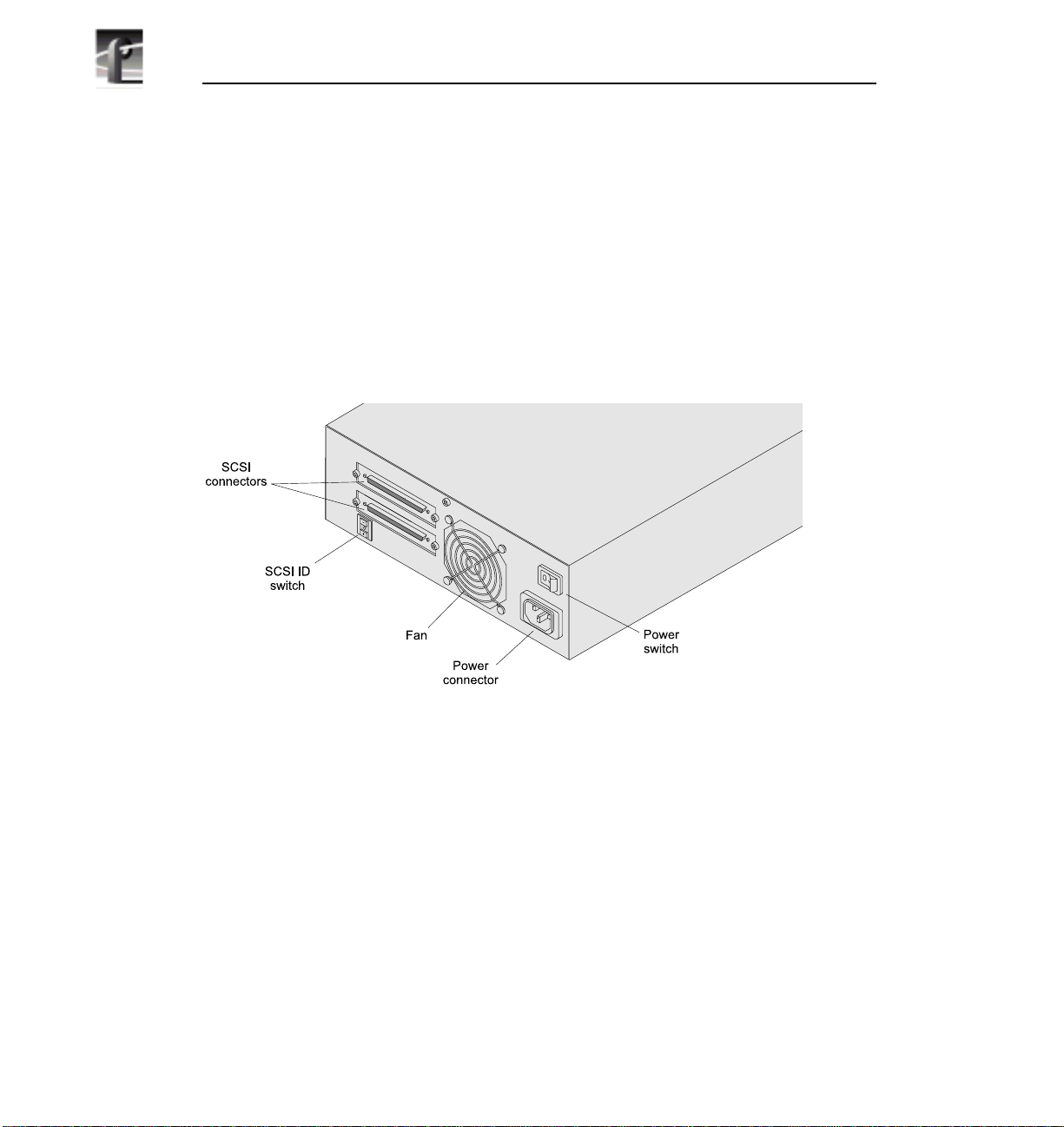
Location of components
When installing the PLS20, refer to Figure 10 for the location of components
on the rear panel.
0183-9
Figure 10. Component locations
Set the SCSI ID
To set the SCSI ID for the tape drive, use a pen or other fine-tipped instrument
to press the SCSI ID switch. Set the SCSI ID to 1 or 2., and ensure that no other
SCSI device on the bus is using the same ID.
NOTE: Changes in the SCSI ID setting take effect after a normal
power-on or SCSI bus reset.
2 Profile PLS20 Data Tape Drive
Page 13

Install the Orientation Pads
The tabletop model includes adhesive pads that you must apply to either the
base or the right side, depending on how you plan to position the tape drive.
These pads protect the tape drive’s surface and allow air to flow through the
vents when the tape drive is positioned on its side.
To install the pads:
1. Remove the backing from four pads. (Five pads are shipped with the tape
drive.)
2. Affix the pads to each corner, approximately -inch (1.3 cm) from the sides.
For a horizontal orientation, place the pads on the bottom. For a vertical
orientation, place the pads on the right side (the side with the external vents).
Install the Orientation Pads
0183-8
Figure 11. Installing the orientation pads
>>> If you want to position the tape drive on its side, you must place the pads on
the right side. Otherwise, the air flow vents will be blocked and the enclosed
tape drive will overheat.
Profile PLS20 Data Tape Drive 3
Page 14

Connect the Drive to the SCSI Bus
The PLS20 receives both data and commands through a single SCSI connector.
Figure 12 shows examples of how to connect your tape drive to a Profile
system.
CAUTION: To avoid damaging the tape drive and the Profile Professional
!
Disk Recorder, make sure that both devices are powered off when you
connect the cables on the back.
1. Connect the tape drive to one of the SCSI ports on the Profile rear panel with
the provided cable.
a. On a PDR100, connect to the SCSI A or SCSI B connector, or to another
device in the chain connected to that bus.
b. On a PDR200, connect to the SCSI B or SCSI D connector, or to another
device in the chain connected to that bus.
2. If the tape drive is the last device on the SCSI bus, install a terminator on the
other connector. If it is not the last device, connect another SCSI cable. Do
not install more than four Profile Data Tape Drives to a single Profile system.
NOTE: You may not connect a PLS200 Profile Library System and
a PLS20 Profile Data Tape Drive to the same Profile system.
However, you may connect up to four Profile Data Tape Drives to the
same Profile system, provided you do not exceed two PLS20s per
SCSI bus.
See Appendix A for cable and terminator requirements.
4 Profile PLS20 Data Tape Drive
Page 15

Connect the Drive to the SCSI Bus
SCSI A
SCSI B
PLS20
PLS20
PDR100
PDR200
SCSI Cable
Terminator
Figure 12. SCSI Bus Connections
Profile PLS20 Data Tape Drive 5
0183-1
Page 16

Connect Power
To connect power to the tape drive:
1. Connect the power cord to the back.
2. Press the power switch to the on (l) position.
Be sure to power on the PLS20 before starting the Profile system to
ensure that the Profile Data Tape Drive is recognized as a SCSI
device.
The tape drive performs its power-on self-test in about 30 seconds. When the
tape drive is ready to accept a cartridge, the LEDs turn off.
➤ Important: Do not insert a cartridge into the tape drive during the
power-on self-test. The tape drive will eject the cartridge.
6 Profile PLS20 Data Tape Drive
Page 17

Operating the Tape Drive
This section describes how to operate your PLS20 Profile Data Tape Drive.
Figure 13 below shows the front-panel components used for tape drive
operation.
Power LED
Status LEDs
LCD display
Door
Unload button
Operating the Tape Drive
0183-4
Figure 13. PLS20 Front Panel Components
Monitoring the Status LEDs
The status LEDs have the following, general meanings:
• Top LED (amber). When this LED is flashing, an error has occurred. When
this LED is on solid, the tape drive needs to be cleaned (see page 14).
• Middle LED (green). When this LED is on, tape is loaded and the tape drive
is ready to begin operations.
• Bottom LED (green). When this LED is flashing, tape motion is occurring.
Profile PLS20 Data Tape Drive 7
Page 18

Table 1 describes the LED combinations that occur during normal tape drive
operation.
Table 1. LED status
Tape Drive State
a
POST
or reset
Top LED
(Error/Cl
ean)
Middle
LED
(Tape
Ready)
Bottom
LED
(Tape
Motion)
a. POST = power-on self-test.
●
●❍❍●●●n/a ●
●❍❍❍
Error
or
failed
POST
❊
Ready
(no tape
loaded)
Ready
(tape
loaded)
Normal
tape
motion
High
speed
motion
Time to
clean
Clean in
progress
n/a n/a n/a n/a ●●
❊
❊
fast
n/a
Legend: ❍ = off ● = on ❊ = flash n/a = not applicable (may be any state)
❊
8 Profile PLS20 Data Tape Drive
Page 19

Monitoring the LCD
If the tape drive includes an LCD, refer to the following table for a detailed list
of messages that may appear.
Table 2. LCD Message Descriptions
Reset messages.
(When the tape drive is reset, the LCD cycles through the following messages.)
Monitoring the LCD
RESET
MODEL:
SUBMOD:
SN:
CODE:
LAST CLN:nn hrs
COMPRESS: ON
COMPRESS: OFF
SINGLE-ENDED
DIFFERENTIAL
WIDEor NARROW
SCSI ID:
LANGUAGE
nn
or
:
or
The first message in the power-on sequence.
The model number of the tape drive.
The submodel number of the tape drive.
The serial number of the tape drive.
The level of the tape drive’s firmware.
The number of hours since the tape drive has last been cleaned.
Compression is turned on or on. Must be off for operation with
a Profile Professional Disk Recorder.
The tape drive has a single-ended or differential SCSI
configuration. Must be Differential.
The tape drive has a wide or narrow SCSI configuration. Must
be wide.
The SCSI ID of the tape drive.
The available foreign languages for the LCD appear when you
perform the following steps:
1. Press and hold the unload button during the reset
sequence. After the SCSI ID message appears, the
LCD cycles through the languages.
2. When the desired language displays, release the
button and the messages appear in that language.
Profile PLS20 Data Tape Drive 9
Page 20

Table 2. LCD Message Descriptions
Tape drive status messages
READY–NOTAPE
LOADING . . . .
READY–TAPE
EJECT ■■■===
EJECT PREVNT
ILLEGAL TAPE
Tape motion messages
READ +■■■===
WRITE+■■■===
PROTECTED
The tape drive is ready to accept a cartridge.
The tape drive is loading the tape.
The tape drive has successfully loaded the tape and is ready for
read/write operations.
The unload button was pressed. The tape drive will eject the
cartridge as soon as it has finished its current operation. The
icon to the left of the Eject message indicates the current suboperation (write, erase, etc.).
The software has disabled the eject function with the
PREVENT/ALLOW MEDIA REMOVAL command. The
tape drive will rewind and unload the tape, but will not eject
the cartridge.
The tape drive detected an incompatible cartridge and ejected
it.
The tape drive is reading or writing data.
The + sign appears when the data is compressed. The boxes
show the amount of tape used.
The tape drive cannot write data because the data cartridge is
write-protected.
ILLEGAL WRT
The tape drive cannot write to the type of data cartridge
inserted. This message remains until an appropriate tape is
inserted or a tape motion command is issued.
>>
<<
<<
SEARCH ■■====
SEARCH ■■====
REWIND ■■====
ERASE ■■====
High-speed search is in progress. The arrows indicate either a
forward or backward search.
Rewind is in progress.
The tape drive is erasing data on the tape.
10 Profile PLS20 Data Tape Drive
Page 21

Table 2. LCD Message Descriptions
Monitoring the LCD
FORMAT ■■■■■■
The drive is repartitioning the tape to the requested format. The
icon to the left of the message displays the current suboperation (write, erase, search, etc.).
Cleaning messages
CLEAN SOON
MUST CLEAN
The tape drive should be cleaned at the next convenient time.
The tape drive must be cleaned after a metal particle tape has
been used in the drive. If you attempt to insert an AME data
cartridge before cleaning the tape drive, the cartridge will be
ejected.
CLEANING . . .
DEPLETED
Cleaning is in progress.
The cleaning tape in the cartridge is depleted and the tape drive
will eject it. Use a new cleaning cartridge.
Error conditions
(When a hardware error occurs, the LCD cycles through the current error code and the
previous three error codes.)
ERR 1:
ERR 2:
ERR 3:
xx yy zz
xx yy zz
xx yy zz
In the error display, xx indicates the fault symptom code, and
yy and zzindicate secondary errors (if any). If an error appears,
contact Exabyte Technical Support.
Profile PLS20 Data Tape Drive 11
Page 22

Selecting Appropriate Data Cartridges
For writing data, use only Profile 170m advanced metal evaporated (AME) data
cartridges, as shown in Figure 14. You must use Profile Media Manager to
format these cartridges before using them in a PLS20 connected to a Profile
Professional Disk Recorder. See the Profile Family User Manual for
information on running Profile Media Manager.
Data cartridges are completely interchangeable between a PLS20 Profile Data
Tape Drive and a PLS200 Profile Library System.
0183-7
Figure 14. A PLS20 170m tape cartridge
Loading Data Cartridges
To load a cartridge:
1. Make sure the tape drive is ready to accept a cartridge (all LEDs are off). Do
not insert a cartridge if the tape drive is still performing its power-on selftest.
2. Set the write-protect switch for the desired operation as shown in Figure 15.
Figure 15. Setting the Write Protection switch
12 Profile PLS20 Data Tape Drive
0183-6
Page 23

3. Insert the cartridge as shown in the Figure 16.
Figure 16. Inserting the tape cartridge
The tape drive loads the tape in approximately 20 seconds. When the middle
LED is on, the tape drive is ready for read and write operations.
Unloading Data Cartridges
Unloading Data Cartridges
0183-5
In normal operation, you should use the appropriate command in Media
Manager (or any other Profile application that supports Profile Library
Systems) to eject or export a data tape from the PLS20. See the Profile Family
User Manual for information on running Profile Media Manager.
In some cases, such as when the PLS20 is not connected to a Profile system,
you may have to manually unload a data tape from the PLS20.
To unload a cartridge, press the unload button. Do not press and hold the
unload button for more than 10 seconds; this can cause a reset under
certain conditions. If the tape drive is free of errors, it performs the following
actions in about one minute:
• Completes any command in process
• Writes any buffered information to tape
• Rewinds the tape to the beginning
• Unloads the tape and ejects the cartridge
Profile PLS20 Data Tape Drive 13
Page 24

NOTE: If an error occurs before or during the unload procedure, the
tape drive suspends the unload sequence. To clear the error, press the
unload button again. The tape drive reattempts the unload sequence,
but does not write data in the buffer.
Resetting the Tape Drive
To reset the tape drive, press and hold the unload button for at least 10 seconds,
or power the drive off and back on again.
If you reset the tape drive while a cartridge is loaded, it rewinds the
tape to the beginning after the reset is complete. The reset may take
as long as two minutes if the tape is positioned near the end.
Cleaning the Tape Drive
When the tape drive requires cleaning, the top (amber) LED turns on. You
should clean the tape drive as soon as possible after this LED turns on. The tape
drive’s cleaning requirements depend on the number of tape motion hours
To clean the tape drive, insert an Profile 8mm Cleaning Cartridge (or a cleaning
cartridge approved by Tektronix for use with the PLS20). When finished, the
tape drive turns off the top LED and ejects the cleaning cartridge.
Cleaning cartridges generally have a useful life of about 12 cycles. Be sure to
change your cleaning cartridges often to ensure the best results.
14 Profile PLS20 Data Tape Drive
Page 25

Packing the Tape Drive
If you are shipping the tape drive to another location or returning it for repair,
pack the tape drive in its original shipping container and packing materials.
CAUTON: To avoid damaging the tape drive and voiding your warranty, use
!
the original shipping materials (or replacement materials from your dealer).
➤ Important: If you are returning the tape drive for service, remove and
keep all cartridges, cables, and terminators.
If you are returning the tape drive to Tektronix, contact Tektronix Product
Support at a number listed at the front of this manual to obtain an RMA number.
Packing the Tape Drive
Profile PLS20 Data Tape Drive 15
Page 26

Specifications
The following tables provide specifications for the PLS20 Profile Data Tape
Drive when used with a Profile Professional Disk Recorder.
Table 3. Tape capacity
Tape Length Data
a
170m
a. PLS20 and PLS200 do not support 22m tapes
Table 4. Date rate
Maximum Data Capacity
20 gigabytes
Maximum Data Transfer Rates
Compressed video
a
data
a. Tape drive compression is not used on compressed video data.
Table 5. Environmental specifications
3 MB/sec.
Operating Environment Specifications
Tape Path Temperature
Range
+5° C to + 45° C
(+41° F to +104° F)
Relative Humidity 20% to 80%; non-condensing
Wet Bulb 26°C (79°F) max
Altitude –304.8 m to +3,048 m
(–1,000 ft to +10,000 ft)
16 Profile PLS20 Data Tape Drive
Page 27

Table 6. Input voltages
Specifications
Input Voltages
Automatic input
Accepts 120 or 240 VAC at 50 to 60 Hz.
voltage selection.
Table 7. SCSI cable specifications
SCSI Cable Specifications
Type Fast Wide Differential
Connector type Wide
68-pin male, high-density, shielded,
AMP 750752-1
Length (maximum)
a
Differential
25 meters (82 feet)
a. Each PLS20 tape drive attached to the SCSI bus uses 0.4 meters (1.31 feet) of cable
length internally. To determine the total length, add 0.4 meters (1.31 feet) to the length
of cable used on the bus for each tabletop tape drive.
Table 8. Terminator specifications
Terminator Specifications
Wide Differential Tektronix Part Number 011-0166-00
Profile PLS20 Data Tape Drive 17
Page 28

Index
Index
A
altitude specifications 16
AME tape 12, 14
Asia and South America, Tektronix Product
Support vii
Asia, Tektronix Product Support vii
B
back panel 2
C
Canada, Tektronix Product Support vii
Canadian Certified AC Adapter viii
Canadian Certified Power Cords viii
Canadian EMC Notice of Compliance viii
cartridges
data capacity 16
loading 12
types to use 12
unloading 13
Certification ix
cleaning
LED indicator 7–8
procedure 14
code level of tape drive 9
compression mode 9
D
data capacity 16
data transfer rate 16
E
EN55022 Class A Warning viii
environmental specifications 16
error conditions
displayed on LCD 11
displayed on LEDs 8
Europe, Tektronix Product Support vii
Exabyte Service 15
F
FCC Emission Control viii
front panel components 7
H
humidity specifications 16
I
input voltages 17
installation 2–6
L
language on LCD 9
LCD
changing the displayed language 9
status messages 9–11
LEDs
status messages 7–8
O
orientation pads for tabletop model 3
P
packing the tape drive 15
performance specifications 16
power
connecting for tabletop model 6
18
Page 29

Index
R
resetting the tape drive 14
returning the tape drive 15
S
SCSI bus
connecting 4
SCSI cable
specifications 17
SCSI ID
displayed on LCD 9
setting 2
serial number of tape drive 9
service 15
shipping the tape drive 15
South America, Tektronix Product Support
vii
T
tape motion LED 7–8
tape ready LED 7–8
Tektronix Product Support vii
temperature specifications 16
termination 4, 17
transfer rate 16
W
World Wide Tektronix Product Support vii
U
United States and Canada, Tektronix Prod-
uct Support vii
unload button
location 7
used for resetting tape drive 14
used for unloading cartridges 13
V
voltages 17
19
Page 30

Index
20
 Loading...