

Page 1
PFR600/E
FIBRE CHANNEL RAID STORAGE SYSTEM
Instruction Manual
071-8266-00
FEBRUARY 2004
the most watched worldwide
Page 2

Copyright Copyright 2004 Grass Valley Group. Grass Valley, California.
Portions copyright Ciprico, Inc. Reprinted with permission.
Printed in th e United States of A m eri ca. All rights reserved. This document may not be copied
in whole or in part, or otherwise reproduced except as specifically permitted under U.S.
copyright law, without the prior written consent of Grass Valley Group Inc., P.O. Box 1114,
Grass Valley, C alifornia 95945 USA .
Trademarks Grass Valley, Profile, and Profile XP are either registered trademarks or trademarks of
Thomson Broadcast and Media Solutions, Inc. in the United States and/or other countries.
Other trademarks used in this document are either registered trademarks or tr ademark s of the
manufacturers or vendors of the associated products. Thomson Broadcast and Media
Solutions, Inc. products are covered by U.S. and foreign patents, issued and pending.
Additional information regarding Thomson Broadcast and Media Solutions, Inc. trademarks
and other proprietary rights may be found at www.thomsongrassval ley.com.
Disclaimer Product options and specifications subject to change without notice. The information in this
manual is furn i shed for informational use only, is subject to chang e without notice, and should
not be construed as a commitment by Thomson Broa dcast and Media Solu tions, I nc. Thomso n
Broadcast and Media Solutions, Inc. assumes no responsibility or liability for any errors or
inaccuracie s that may appear in this publi cation.
U.S. Government
Restricted Rights
Legend
Use, duplicat ion, o r disclos ure by t he Unite d States Governme nt is su bject to restric tions as s et
forth in subparagraph (c)(1)(ii) of the Rights in Technical Data and Computer Software clause
at DFARS 252.277-7013 or in subparagraph c(1) and (2) of the Commercial Computer
Software Re st ri cted Rights c l ause at FAR 5 2.227-19, as applicable. Manufacturer is Thomson
Broadcast and Media Solutions, Inc., P.O. Box 59900, Nevada City, California 95959-7900
U.S.A.
Revision Status
Rev Date Description
20 February 2004 First releas e. 071-8266-00
2 PFR 600/E Instruction Manual 20 February 2004
Page 3

Contents
Safety Summaries
Preface
About this manual.................................................................................................................9
Using the Profile XP documentation Set .........................................................................9
Manual descriptions.......................................................................................................10
How this manual is organized........................................................................................11
Getting more information....................................................................................................12
On-line manuals ................ ......... ........ ......... ........ ........ ........................................... .......12
Chapter 1 About the PFR600 Series
PFR6 00 Series features.....................................................................................................15
PFR600 features...........................................................................................................16
Capacity and redundancy..............................................................................................16
PFR6 00 Series components..............................................................................................17
Chassis..........................................................................................................................19
Midplane........................................................................................................................19
Disk modules.................................................................................................................20
PFR600/E circuit board modules...................................................................................21
PFR 600 RAID Storage Chassis circuit board modules............................................21
PFR600E RAID Expansion Chassis circuit board modules......................................24
Power supplies..............................................................................................................25
Fan modules..................................................................................................................25
Configurations....................................................................................................................26
Chapter 2 PFR600 Series Installation Information
Installation requirements................. ........ ......... ........ ........ ......... ........ ......... ........................27
Site requirements..........................................................................................................27
Power........................................................................................................................27
Cooling......................................................................................................................27
Chassis address setting requirement............................................................................28
Cabling requirements ....................................................................................................29
Binding disk modules into groups..................................................................................30
Installing a PFR600/E in an equipment rack......................................................................31
Unpacking the chassis...................................................................................................31
Installing the rack mounts..............................................................................................32
Inserting the PFR600/E chassis in the rack..................................................................34
Installing the chassis with drive the support bracket.................................................34
Installing chassis without the drive support bracket..................................................34
PFR6 00/E power-up and initialization................................................................................36
Connecting electrical cables..........................................................................................36
Powering-up the PFR600/E system..............................................................................37
PFR6 00/E power-down......................................................................................................38
Battery Backup recharge....................................................................................................38
Chapter 3 Servicing the PFR600 Series RAID
Maintenance procedures using GVG Disk Utility ...............................................................40
Monitoring PFR600 Series RAID status using NetCentral.................................................40
Interpreting disk module LEDs ...........................................................................................41
Interpreting rear panel status LEDs....................................................................................42
LBB 7-segment display codes............................................................................................43
Removing and installing disk modules ...............................................................................44
20 February 2004 PFR600/E Instruction Manual 3
Page 4

Contents
Moving disk modules.....................................................................................................44
Removing a disk module...............................................................................................45
Installing disk module....................................................................................................46
Replacing the Loop Bypass Board (LBB) or
RAID Controller.............................................................................................................47
Removing the LBB or RAID Controller..........................................................................47
Installing the LBB or RAID Controller............................................................................48
Replacing data ports..........................................................................................................49
Replacing a power supply..................................................................................................50
Replacing the fan module..................................................................................................51
Appendix A Technical Specifications and
Operating Limits
AC power requirements.....................................................................................................53
Size and weight..................................................................................................................53
Cable lengths.............................. ......... ........ ......... ........ ........ .............................................53
Environmental limits...........................................................................................................54
Index.................................................................................................................................55
4 PFR 600/E Instruction Manual 20 February 2004
Page 5

Safety Summaries
General Safety Summary
Review the following safety precautions to avoid injury and prevent damage
to this product or any products connected to it.
Only qualified personnel should perform service procedures.
While using this product, you may need to access other parts of the system.
Read the General Safety summary in other system manuals f or warnings an d
cautions related to operating the system.
Injury P r e caution s
Use Correct Power
Cord
Ground the Product This product is grounded through the grounding conductor of the power
Do Not Operate Without Covers
Do Not operate in
Wet/Damp
Conditions
Do Not Operate in an
Explosive
Atmosphere
Avoid Exposed
Circuitry
Power cords for this equipment, if provided, meet all North American
electrical codes. Operation of this equipment at voltages exceeding 130
VAC requir es power supply cords which comply with NEMA
configurations. International power cords, if provided, have the approval
of the count ry of use.
cord. To avoid electric shock, the grounding conductor must be connected
to earth ground. Before making connections to the input or output terminals
of the product, ensure t hat the product is prope rl y grounded .
To avoid electric shock or fire hazard, do not operate this product with
covers or pa nels removed.
To avoid electric shock, do not operate this product in wet or damp
conditions.
To avoid injury or fire hazard, do not operate this product in an explosive
atmosphere.
To avoid injury, remove jewelry such as rings, watches, and other metallic
objects. D o not to uc h exp os e d con ne cti o ns and c ompon e nts wh en po we r is
present.
Product Dam age P recautions
Use Proper Power
Source
Provide Proper
Ventilation
Do Not Operate With
Suspected Failures
20 February 20 04 PFR600 /E Ins tru c t ion Manual 5
Do not operate this product from a power source that applies more than the
voltage specified.
To prevent product overheating, provide proper ventilation.
If you suspect there is damage to this product, have it inspected by qualified
service personnel.
Page 6
Safety Terms and Symbols
Terms in This
Manual
!
!
Terms on the
Product
Symbols on the
Product
These terms may appear in this manual:
WARNING: Warning statements identify conditions or practices that can
result in personal injury or loss of life.
CAUTION: Caution statements identify conditions or practices that may
result in damage to equ ipment or oth er property, or which may cause
equipment crucial to your business environment to become temporarily
non-operational.
These terms may appear on the product:
DANGER indicates a personal injury hazard immediately accessible as one
reads the marking.
WARNING indicates a personal injury hazard not immediately accessible
as you read the marking.
CAUTION indicates a hazard to property including the product.
The following symbols may appear on the product:
DANGER high voltage
!
ATTENTION – refer to manual
Service Safety Summary
Do Not Service
Alone
Disconnect Power To avoid electric shock, disconnect the main power by means of the power
Use Care When
Servicing With
Power On
Do not perform internal service or adjustment of this product unless another
person capable of rendering first aid and resuscitation is present.
cord or, if provided, the power switch.
Dangerous voltages or currents may exist in this product. Disconnect power
and remove battery (if applicable) before removing protective panels,
soldering, or replacing components.
To avoid electric shock, do not touch exposed connections
6 PFR600/E Instruction Manual 20 Februa ry 2004
Page 7

Certifications and Compli ances
Canadian Certified
Power Cords
FCC Emission
Control
Canadian EMC
Notice of
Compliance
Canadian approval includes the products and power cords appropriate for
use in the North America power network. All other power cords supplied
are approved for the country of use.
This equipment has been tested and found to comply with the limits for a
Class A digital device, pursuant to Part 15 of the FCC Rules. These limits
are designed to provide reasonable protection against harmful interference
when the equipment is operated in a commercial environment. This
equipment generates, uses, and can radiate radio frequency energy and, if
not installed and used in accordance with the instruction manual, may cause
harmful interference to radio communications. Operation of this equipment
in a residential area is likely to cause harmful interference in which case the
user will be required to correct the interference at his own expense. Changes
or modifications not expressly approved by Grass Valley Group can affect
emission compliance and could void the user’s authority to operate this
equipment.
This digital apparatus does not exceed the Class A limits for radio noise
emissions from digital apparatus set out in the Radio Interference
Regulations of the Canadian Department of Communications.
Le présent appareil numérique n ’émet pas de br uits radioélectriques
dépassant les limites applicables aux appareils numériques de la classe A
préscrites dans le Règlement sur le brouillage radioélectrique édicté par le
ministère des Communications du Canada.
EN55022 & EN55024
Class A Warning
FCC Emission
Limits
This product has been evaluated for Electromagnetic Compatibility under
the EN 55022 a nd 550 24 sta nd ard s fo r Emis si ons a nd Im mu nit y an d mee ts
the requirements for E4 environment.
This product complies with Class A (E4 environment). In a domestic
environment this product may cause radio interference in which case the
user may be required to take adequate measures .
This device complies with Part 15 of the FCC rules. Operation is s ubject
to the following two conditions: (1) this device may not cause harmful
interference, and (2) this device must accept any interference received,
including interference that may cause undesired operation.
20 February 20 04 PFR600 /E Ins tru c t ion Manual 7
Page 8
Safety Certification
This product has been evaluated and meets the following Safety
Certification Standards:
Standard Designed/teste d for compliance with:
UL1950 Safety of Information Technology Equipment, including
IEC 950 Safety of Information Technology Equipment, including
Electrical Business Equipment (Third edition).
Electrical Business Equipment (Second edition, 1991).
CAN/CSA C22.2,
No. 950-95
EN60950 Safety of Information Technology Equipment, including
Safety of Information Technology Equipment, including
Electrical Business Equipment.
Electrical Business Equipment 1992.
ATTENTION This product has been designed and certified to comply with certain
regulatory requirements pertaining to Information Technology
Equipment. This pr oduct has not been designed for us e as a medical
device. Without limitation of the foregoing, this product is not intended
and has not been certified for use in a hospital or clinical environment to
diagnose, treat, or monitor patients under medical supervision, and is not
intended and has not been certified to make physical or electrical contact
with patients, nor to transfer energy to or from patients and/or to detect
such energy transfer to or from patients.
8 PFR600/E Instruction Manual 20 Februa ry 2004
Page 9
Preface
About this manual
The PFR600/E Fibre Channel RAID Storag e Chassis prov ides RAID protected
storage for Profile XP Media Platforms and Grass Valley Open SANs. If you are
responsible for installing and servicing the PFR600/E in one of these systems, you
should read this manual.
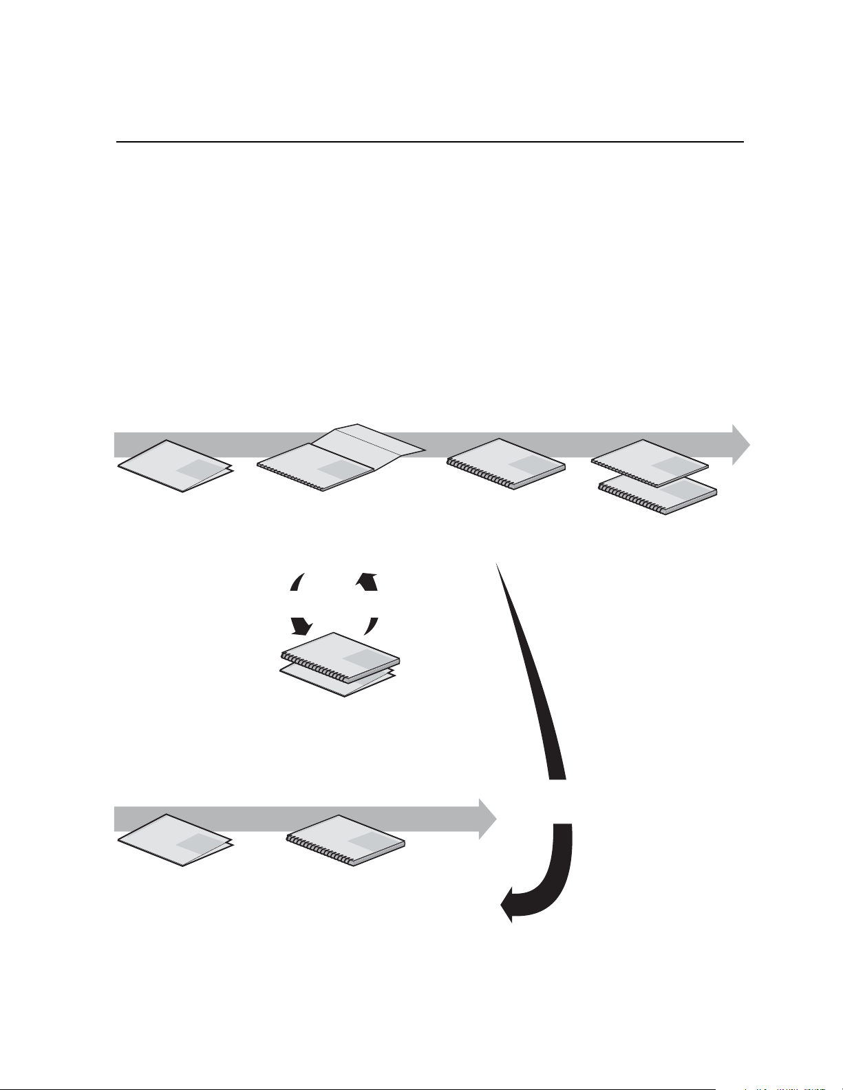
Using the Prof ile XP documentat ion Set
This manual is part of a full set of support documentation for the Profile XP Media
Platform. The following figure illustrates how to use the Profile XP documentation
depending on the task you are performing. For instructions on connecting and
configuring the PFR600 Series Fibre Channel RAID Storage Chassis, consult the
Profile XP Installation Guide (local storage) or Open SAN Instruction Manual
depending on the system you are installing.
Path for the Installer
s
ie
r
e
S
Profile XP
P
X
f
o
y
il
m
Manual
a
F
Grass Valley Group
Release Notes
Contains the latest
information about Profile XP
hardware and software
shipped with your system.
Grass Vall
ey Group
Profile XP
Manual
s
e
i
r
e
S
P
X
f
o
y
l
i
m
a
F
Installation Guide
Contains essential steps for
installing your Profile XP
system with local storage,
using factory default settings.
Use alternate procedures
for shared storage option.
System Guide
Contains the product description
and step-by-step instructions for
modifying system settings.
Grass Valley Group
Profile XP
s
e
i
r
e
S
P
X
f
o
y
l
i
Manual
m
a
F
Grass Valley Group
Grass Valley Group
Profile XP
s
e
i
r
e
S
P
X
f
o
y
l
i
Manual
m
a
F
s
e
i
r
e
S
P
X
f
o
Profile XP
y
l
i
Manual
m
a
F
Other Manuals
These manuals include:
- PFC500 Instruction Manual
- PFR500 Instruction Manual
- PFR600 Instruction Manual
- Profile XP Service Manual
Path for the Operator
up
s
e
i
r
e
S
Profile XP
P
X
f
o
ly
i
m
Manual
a
F
Grass Valley Gro
Release Notes
Contains the latest
information about Profile XP
hardware and software
shipped with your system.
ey Group
Grass Vall
Grass Valley Group
Profile XP
Profile XP
Manual
s
e
i
r
e
S
P
X
f
o
y
l
i
Manual
m
a
F
s
ie
r
e
S
P
X
f
o
ly
i
m
a
F
Open SAN
Instruction Manual and Release Notes
Contains instructions for installing storage
that is shared by multiple Profile XP systems.
s
e
i
r
e
Profile XP
S
P
X
f
o
y
l
i
Manual
m
a
F
Grass Valley Group
User Manuals
Contains complete instructions for using
Profile applications. These manuals include:
- Profile XP User Manual
- Other user manuals you received with
optional Profile applications.
Installers consult
the User Manuals
as needed.
20 February 2004 PFR 600/E Instruction Manual 9
Page 10

Manual descripti on s
• Installation Guide (for each Profile XP Model) This guide provides step-by-step
instructions for installing the Profile XP Media Platform using factory default
settings for all record/play channels. Factory default settings are indicated within
the guide. After installing the Profile XP system using this installation guide, you
can refer to this Profile XP System Guide to customize system settings for your
installation.
Profile XP System Guide This guide provides all the information you need to go
•
beyond factory default settings and customize your system’ s configuration to meet
your site-specific needs. This guide also provides an overview of your Profile XP
system, and provides all the specifications you need to integrate the Profile XP
Media Pla tform into your ope rat ion.
Profile XP User Manual Contains complete instructions for using Profile
•
applications to operate the Profile XP Media Platform.
Profile XP Service Manual Contains information for servicing the Profile XP
•
Media Platform, and includes procedures for the following tasks:
- Problem analysis using symptom, problem, solution tables.
- Runnin g di ag nostics loca l ly and remotel y
- Set up and operation of NetCentral monitoring software.
- Replacing field replaceable units.
Profile XP Release Notes Contains the latest information about the Profile
•
hardware and the software release shipped on your system. This information
includes software specifications and requirements, feature changes from the
previous releases, helpful system administrative information, and any known
problems.
PFR Series Instruction Manual Contains information for servicing the PFR600
•
Series Fibre Channel RAID Storage Chassis including step-by-step procedures for
replacing field replaceable units.
10 PFR600/E Instruction Manual 20 February 2004
Page 11

How this manual is organized
The PFR Series Instruction Manual is organized around t he tasks you’l l be
performing to install and service your Fibre Channel RAID Storage System. You can
see this reflected in the chapter titles chosen for this manual. The following identifies
and describes the chapters included in this manual:
Chapter 1 - About the PFR600 Series
Introduces the PFR600 Series Fibre Channel RAID Storage Chassis (PFR600) and
the RAID Expansion Chassis (PFR600E). You can read this chapter to get familiar
with the RAID Storage Chassis key features and components.
Chapter 2 - PFR 600 Series Installation Information
Describes how to install a RAID Storage Chassis and RAID Expansion Chassis,
including rack mounting. Refer to the Profile XP System Guide for connection and
configuration information.
Chapter 3 - Servicing the PFR600 Series RAID
Describes how to rep lace CRUs , such as dis k module s, and a dd disk m odules an d
redundant CRUs.
Appendix A - Technical Specifications and Operating Limits
This appendix consists of electrical and environmental specifications.
How this manual is organized
Glossary
The Glossary explains terms used throughout this manual.
20 February 2004 PFR 600/E Instruction Manual 11
Page 12

Getting more information
In addition to printed documents, Profile XP product information is available in
on-line manuals. Use these as additional sources for information.
On-line manuals
Electronic versions of the following manuals are located on the system drive of your
Profile XP Media Platform and on the Profile XP software CD-ROM.
• Installation Guide (for your model)
• Profile XP System Guide
• Profile XP User Manual
• Profile XP Service Manual
• PFR Series Instruction Manual
• Profile XP Release Notes
You can view these manuals using Adobe Acrobat Reader which is also pre-installed
on your Profile XP system .
12 PFR600/E Instruction Manual 20 February 2004
Page 13

Grass Valley Product Support
To get technical assistance, check on the status of problems, or report new problems,
contact Grass Valley Product Support via e-mail, the Web, or by phone or fax.
Web Technical Support
To access support information on the Web, visit the product support Web page on the
Grass Valley Web site. You can download software or find solutions to p roblems by
searching our Frequently Asked Questions (FAQ) database.
World Wide Web: http://www.thomsongrassvalley.com/support/
Technical Support E-mail Address: gvgtechsupport@thomson.net.
Phone Support
Use the following information to contact product support by phone during business
hours. Afterhours phone support is available for warranty and contract customers.
United States (800) 547-8949 (Toll Free) France +33 (1) 34 20 77 77
Latin America (800) 547-8949 (Toll Free) Germany +49 6155 870 606
On-line manuals
Eastern Europe +49 6155 870 606 Greece +33 (1) 34 20 77 77
Southern Europe +33 (1) 34 20 77 77 Hong Kong +852 2531 3058
Middle East +33 (1) 34 20 77 77 Italy +39 06 8720351
Australia +61 3 9721 3737 Netherlands +31 35 6238421
Belgium +32 2 3349031 Poland +49 6155 870 606
Brazil +55 11 5509 3440 Russia +49 6155 870 606
Canada (800) 547-8949 (Toll Free) Singapore +656379 1390
China +86 106615 9450 Spain + 34 91 512 03 50
Denmark +45 45968800 Sweden +46 87680705
Dubai + 971 4 299 64 40 Switzerland +41 (1) 487 80 02
Finland +35 9 68284600 UK +44 870 903 2022
Authorized Support Representative
A local authorized support representative may be available in your country. To locate
the support representative for your country, visit the product support Web page on the
Grass Valley Web site.
Profile Users Group
You can connect with other Profile XP Media Platform users to ask questions or share
advice, tips, and hints. Send e-mail to profil e-users@ thoms on.net to join the community
and benef it from the experience of others.
20 February 2004 PFR 600/E Instruction Manual 13
Page 14

14 PFR600/E Instruction Manual 20 February 2004
Page 15
Chapter
1
About the PFR600 Series
This chapter introduces the PFR600 Series Fibre Channel RAID Storage Chassis.
Topics include:
• PFR600 Seri es fea ture s
• PFR600 Se rie s comp on e nts
• Configurations
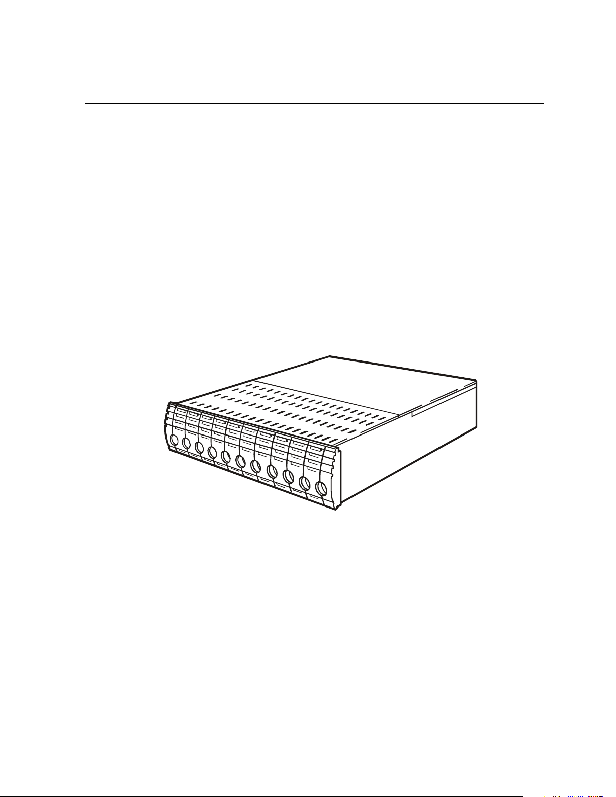
PFR600 Series features
The PFR600 Series Fibre Channel RAID Storage Chassis is a high performance, high
availability mass storage system. High-bandwidth storage is made possible using
Fibre Channel Arbitrated Loop (FC-AL) technology. The PFR600 Series’s modular,
scalable design provides additional disk storage as your needs increase.
2359
Feature highlights:
• Ten drives in a 3U vertical rack space
• No single point of failure
• Many active components are hot-serviceable
• Scalable expansion using RAID Expansion Chassis
• Optional dual RAID controllers provide Fibre Channel failover
• Copper or Optical Fibre Channel Small Form-Factor Pluggable interface (SFP)
The PFR600 Series utilizes dual FC-AL technology, allowing two loop
configurations within a single chassis. Port-Bypass Circuits have been added to
maintain loop integrity during failures without user intervention. Each loop and
associated Port Bypass Circuits along with all other active components are on
20 February 2004 PFR600/E Instruction Manual 15
Page 16

Chapter 1 About the PFR600 Series
redundant modules. This improves serviceability and increases fault tolerance by
eliminating any single point of failure. With two RAID Controllers, the two loops
within a single standard chassis are configured as a single loop with a backup loop in
standby mode.
PFR600 features
The PFR600 controllers provide enhanced performance of up to 2 Gb/s transfer rates
using SCSI protocol. Interchangeable SFPs (Small Form-factor Pluggable) adapters
allow you to configure your PFR600 for operation in a copper or fiber-optic (optical)
cabling environment. Generally, use optical SFPs and cables, which are rated at
2Gb/s, wherever possible, such as to connect a PFR600 to a Profile XP Media
Platform equipped with a Fibre Channel Disk II card, or to a Fibre Channel switch in
an Open SAN installation. Use copper SFPs and cables, which are rated at 1 Gb/s, to
connect a PFR600 directly to an older Profile XP Media Platform that does not
contain a Fibre Channel Disk II card.
The PFR600 su pp orts up to four PFR6 00E RAID Expansio n Ch as s is. It doe s not
support connection to PFR500E RAID Expansion Chassis. Always use optical SFPs
and cables to connect the PFR600 to PFR600E RAID Expansion Chassis to ensure
optimal performance of your RAID storage system.
Capacity and redundan cy
The PFR600 Series contains five or ten half-height 3.5" Fibre Channel Arbitrated
Loop (FC-AL) disk drives. The chas sis also support s one or two hardware RAID
Controllers in one 3U high rack-mountable chassis. The PFR600 Series currently uses
36GB, 73GB or 146GB drive capacities. With ten drives, one chassis holds up to
360GB, 730GB or 1.46TB depending on the disk drive option.
The RAID Expansion Chassis provides additional storage capacity. It is an identical
chassis with two Loop Bypass Board installed. Up to four RAID Expansion Chassis
can be connected to a single PFR600 Series comprising a single disk-array storage
system with a total of 60 driv es and 2. 16TB, 4.38TB or 8.88TB of stora ge de pending
on the disk drive option. The built-in chassis daisy-chaining capabilities provide for
cost effective storage expansion as requirements grow.
16 PFR600/E Instruction Manual 20 February 2004
Page 17

PFR600 Series components
The PFR600 Series components are:
• The chassis with passive midplan e board
• One or two RAID controllers (not present i n expansion units)
• One or t wo Loop Bypass B oards
• As many as ten Fibre Channel disk drives per chassis
• Two power supplies
• Two fa n modules
The disk drives, power supplies, and fan modules are hot-swappable field replaceable
units (FRUs), which means you can add or replace them while the PFR600 Series is
powered up.
IMPORTANT: You must not hot swap operational devices such as disk drives
without first disabling the target component using the Grass Valley Disk Utility.
An optional second RAID Controller Module in the PFR600 Series, allows for
continued access to the PFR600 Series if the primary RAID Controller fails. Adding
a second RAID Controller to the same chassis is not intended to increase performance,
but rather to add re dundanc y
for detailed connection and configuration instructions.
. Refer to your Profile XP PVS Series Installation Guide
PFR600 Series components
NOTE: Hot swapping disk drives may occasionally cause a slight interruption in
record or play operations.
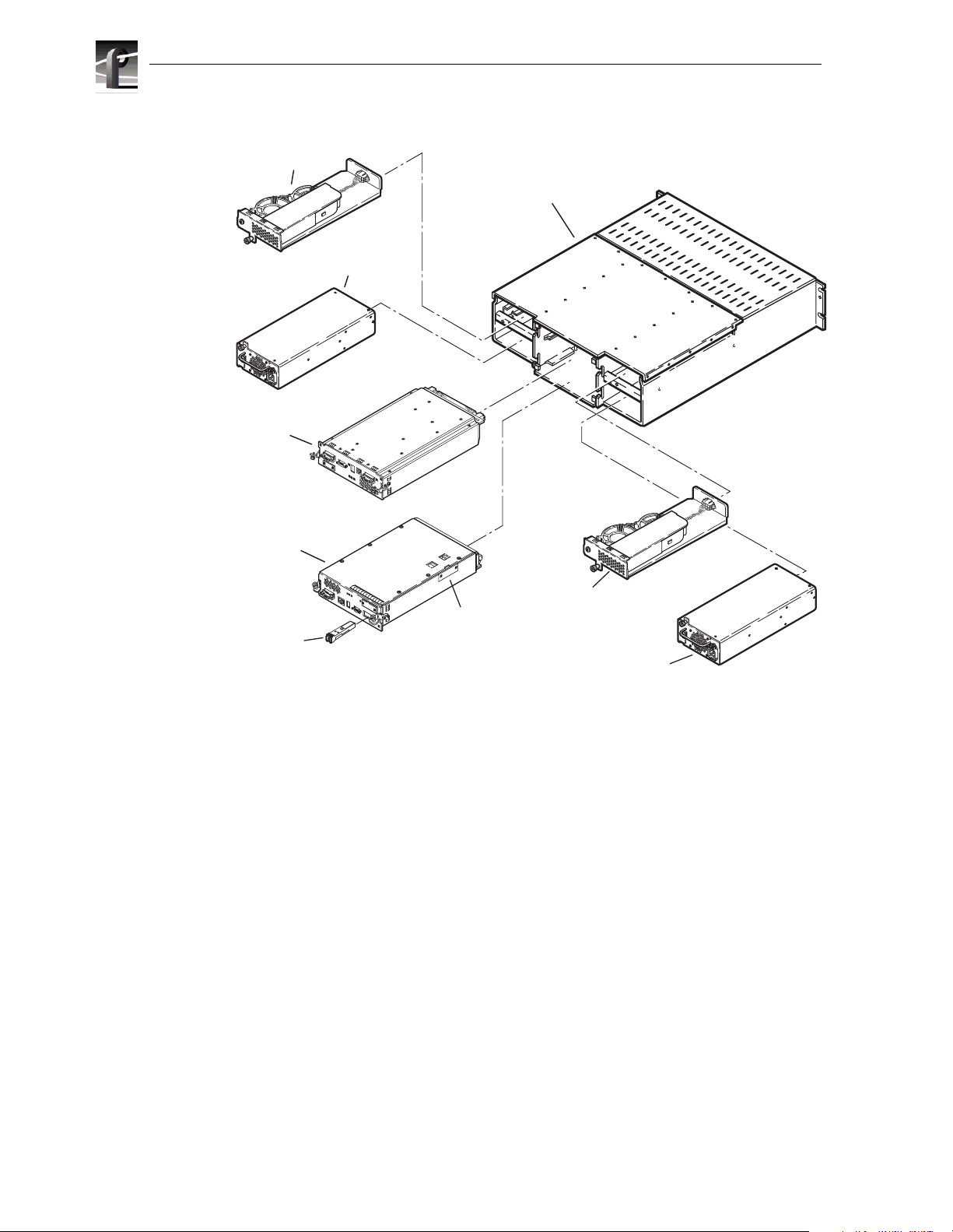
The following figure shows the RAID Storage Chassis components. Details on each
component follow the figure.
20 February 2004 PFR600/E Instruction Manual 17
Page 18
Chapter 1 About the PFR600 Series
Fan Module A
Power Supply A
LBB B
Chassis
LBB A
Fan Module B
Battery Backup
SFP
Unit (BBU)
Power Supply B
NOTE: Every PFR600 Series RAID controller includes a backup battery so that if
electrical power is lost, data stored in cache memory will be saved. Data store cache
is not used in the PFR600 Series, so the Battery Backup module is not used, even
though it ships as part of the LBB module.
18 PFR600/E Instruction Manual 20 February 2004
Page 19

Chassis
Chassis
The chassis is a sheet-metal housing which contains a passive midplane and chassis
slots for the RAID Controllers, or Loop Bypass Boards, disk drives, power supplies,
and the fan modules.
Each chassis includes a chassis add ress switch on t he midpl ane boar d that mus t be set
to a unique address 0 thro ugh 9 during installation. Refer to your PVS Series
Installation Guide or the Open SAN Installation Manual for information on setting the
chassis address switch depending how the PFR600 Series RAID is used. See also,
“Chassis address setting requirement” on page 28.
The following diagram shows how disk modules are identified based on the chassis
address and physical location. The chassis with an address set to 0 contains drives
from 1 to 10; the chassis with an address set to 1 contains drives from 11 to 20; and
so forth.
Midplane
The midplane distributes power and signals to all the chassis components. All FRUs
plug directly into midplane connectors. The midplane includes a chassis address
switch that must be set during installation. Refer to “Chassis address setting
requirement” on page 28 for information on setting the chassis address.
12345
Disk Modules
678910
20 February 2004 PFR600/E Instruction Manual 19
Page 20

Chapter 1 About the PFR600 Series
Disk modules
Each disk module consists of a Fibre Channel disk drive in a carrier assembly. If a
disk drive fails, and needs replacing, you can do so while the RAID Storage Chassis
is powered up. Replacement disk drives take 3-4 minutes to begin rebuild after being
installed. (See “Removing and installing disk modules” on page 44.)
The disk drives are 3.5-inch FC-AL drives that conform to the Fibre Channel
Arbitrated Loop (FC-AL) standards and support dual-port FC-AL interconnects
through the two RAID controllers and their cabling.
CAUTION: Once the PFR600 Series RAID is installed and configured, the disk
!
modules become slot dependent. Moving disk modules between physical slots will
result in loss of data and the need to reconfigure the system.
2299
1
2
20 PFR600/E Instruction Manual 20 February 2004
Page 21

PFR600/E circuit board modules
There are two circuit board modules used: the Loop Bypass Board module (LBB) and
the RAID Controller module. The LBB module contains one Loop Bypass Board
which provides an internal Fibre Channel loop for the disk modules installed in the
chassis. The RAID Controller module also contains a Loop Bypass Board plus a
RAID Controller board used to manage the disk drives and provide a Fibre Channel
interface to the Profile system.
PFR600 RAID Storage Chassis circuit board modules
The PFR600 includes one or two RAID Controller modules. Two RAID Controller
modules are installed when the redundant Fibre Channel option is installed. This
provides redundant Fiber Channel interface ports t o t he Profile sy st em or Fibre
Channel switch fabric.
The following figure shows a PFR600 RAID Storage Chassis with the two RAID
Controller Modules installed. RAID controllers can be installed in either position, top
or bottom. The one in the bottom position is identified as Controller A, the one in the
top position is identified as Controller B.
7 Segment LED
(displays chassis address)
Host Fibre
Channel Port
Serial
Port
Ethernet
Port
PFR600 /E ci rcuit board modules
Fibre
Channel
Loop Port
PFR600
Fibre
Channel
Loop Port
Ethernet
Port
7 Segment LED
(displays chassis address)
Serial
Port
RAID Controller B
RAID Controller A
Host Fibre
Channel Port
20 February 2004 PFR600/E Instruction Manual 21
Page 22

Chapter 1 About the PFR600 Series
Each RAID Controller module includes a Loop Bypass Board (LBB). These boards
provides internal Fibre Channel loops for the disk modules. In the event of an LBB
module failure, the faulty loop is bypassed and all disk drives failover to the
remaining LBB module.
The LBB in the PFR600 RAID Controller module has two Fibre Channel ports: the
Fibre Channel Host Port and the Fibre Channel Loop Port. Copper or optical SFP
(Small Form-factor Pluggable) modules are used in the Host Fibre Channel ports to
connect Fibre Channel cabling to a Profile XP Media Platform or to a Fibre Channel
switch in an Open SAN fabric, respectively. Optical SFP modules are used in the
Fibre Channel Loop ports to connect to a PFR600E. This extends the Fibre Channel
loop of the corresponding PFR600 chassis. There is a port status LED for each Fibre
Channel port. Refer to “Interpreting rear panel status LEDs” on page 42.
Tab
Optical SFP adapter
Remove
white cap
Remove
white cap
22 PFR600/E Instruction Manual 20 February 2004
Page 23

PFR600 /E ci rcuit board modules
When the redundant Fiber Channel option is not installed in the PFR600 RAID
Storage Chassis, only one RAID Controller is installed along with one LBB module
as shown in the following figure. The LBB module and the LBB contained in the
RAID Controller module provide the two LBBs required in the PFR600 Series Fibre
Channel RAID Storage Chassis. The LBB and RAID Controller modules are clearly
labeled on the rear panel of each canister.
7 Segment LED
(displays chassis address)
Serial
Port
Ethernet
Port
Fibre
Channel
Loop Port
Loop Bypass Board B
RAID Controller A
PFR600
Fibre
Channel
Loop Port
Ethernet
Port
7 Segment LED
(displays chassis address)
Serial
Port
Host Fibre
Channel Port
An RJ-type connector is provided for Ethernet network connection, which is used for
SNMP monitoring and firmware downloads. A DB-9 serial port is provided for serial
communications with a console program to configure the RAID Controller’s IP
address, subnet mask, SNMP domain, and other network settings. These settings are
required to use the NetCentral monitoring software. Refer to your PVS Ser i es
Installation Guide or the Open SAN Instruction Manual for information how these
connectors are used.
20 February 2004 PFR600/E Instruction Manual 23
Page 24

Chapter 1 About the PFR600 Series
PFR600E RAID Expansion Chassis circuit board modules
The PFR600E RAID Expansion Chassis always has two LBB modules installed as
shown in the following figure. The LBBs are identical, and can be used in either the
top or the bottom position.
7 Segment LED
Left
Fibre Channel
Loop Port
(displays chassis address)
Serial
Port
Ethernet
Port
Right
Fibre Channel
Loop Port
Loop Bypass Board B
Loop Bypass Board A
PFR600E
Left
Fibre Channel
Loop Port
Ethernet
Port
7 Segment LED
(displays chassis address)
Serial
Port
Right
Fibre Channel
Loop Port
The LBB in the PFR600E has two Fibre Channel ports: the Left and Right Fibre
Channel Loop Ports. 2Gb/s optical SFPs are used in these ports to connect Fibre
Channel cabling to a PFR600 or PFR600E. This extends the Fibre Channel loop of
the corresponding PFR600 chassis. There is a port status LED for each Fibre Channel
port. Refer to “Interpreting rear panel status LEDs” on page 42.
A DB-9 serial port is provided for serial communications with the PFR600 through
the supplied cable. Refer to your PV S Series Installation Guide or the Open SAN
Instructi on Manual for connection info rm at ion .
NOTE: The PFR600E Expansion chassis and P FR600 Controller chassis must be
powered on and off in the proper sequence. Refer to proper power procedures in
Chapter 2, “PFR600 Series Installation Information”.
24 PFR600/E Instruction Manual 20 February 2004
Page 25

Power supplies
There are two auto-ranging power supplies, each with its own power cord and standby
switch. Each supply supports a fully configured PFR600 Series RAID and shares load
currents with the other supply, if it is present. The power supplies are designed so as
to protect the disk drives if you install them while the PFR600 Series RAID is
powered up. A disk with power-related faults will not adversely affect the operation
of any other disk.
Each power supply has status LEDs visible from the rear panel. The status LEDs are
described in the “Interpreting rear panel status LEDs” on page 42.
A retaining screw secures the power supply in place. You can add or remove one
power supply in the RAID Storage Chassis while the RAID Storage Chassis is
powered up.
Fan modules
There are two fan modules used to cool the components installed in the PFR600
Series RAID chassis. The fan modules connect to the midplane board for power.
One status LED on the rear panel of the fan module indicates status. The status LED
is described in the “Interpreting rear panel status LEDs” on page 42.
Power supplies
A retaining screw on the fan module holds the module in place.
NOTE: If power is connected, fans run at low speed even with the power supply
switches in standby position.
20 February 2004 PFR600/E Instruction Manual 25
Page 26

Chapter 1 About the PFR600 Series
Configurations
The RAID Storage Chassis minimum and maximum configurations are as follows.
PFR600
Configuration
minimum 1 1 2 5
maximum 2 0 2 10
RAID Controller
Module
(Includes one LBB)
Loop Bypass
Board Module
Power Supplies/Fan
modules
Disk Modules
The maximum configuration provides the most redundancy, and therefore the highest
degree of system availability.
The PFR600E RAID Expansion Chassis minimum and maximum configurations are
as follows.
PFR600/E
Configuration
minimum 2 2 5
maximum 2 2 10
Loop Bypass
Board Module
Power Supplies/Fan
modules
Disk Modules
IMPORTANT : Gr ass Valley does not support mi xing disk dri ves of differing
capacities in any RAID chassis. All disk drives in any RAID chassis must be of the
same capacity. For example, if a PFR600 and a PFR600E are connected, all the
disk drives in both the PFR600 and the PFR600E must be of the same capacity.
26 PFR600/E Instruction Manual 20 February 2004
Page 27

Chapter
2
PFR600 Series Installation Information
This chapter describes information you’ll need to install the PFR600 Series Fibre
Channel RAID Storage Chassis (PFR600/E). Major topics are:
• Installation requirements
• Installing a PFR600/E in an equipment rack
• PFR 6 00/E power-up and initialization
• PFR600/E power-down
Installation requirements
This section describes the following requirements:
• “Site requirements” on page 27
• “Chassis address setting requirement” on page 28
• “Cabling requirements” on page 29
• “Binding disk modules into groups” on page 30
Site requirements
For proper PFR600/E operation, the installation site must conform to certain
environmental specifications. These are detailed below and in Appendix A, “Technical
Specifications and Operating Limits”.
Power
Refer to “AC power requirements” on page 53 for AC power requirements. The values
indicate either the values for the power cord of a PFR600/E with a single power supply,
or the total values shared by the line cords of two power supplies in the same PFR600/
E, with the division between the power cords and supplies at the current sharing ratio. If
one of the two power supplies fails, the remaining supply and cord must support the full
load. You must use a rack mount cabinet with ac power distribution, and have main
branch ac distribution that can handle these values for the number of PFR600s and
PFR600Es that you will interconnect.
Cooling
Make sure your site has air conditioning of the correct size and placement to maintain
the specified ambient temperature range. The air conditioning must be able to handle the
requirements of the PFR600s and any connected PFR600Es as indicated under
“Environmental limits” on page 54.
20 February 2004 PFR600/E Instruction Manual 27
Page 28

Chapter 2 PFR600 Seri es Inst al la tion Information
Chassis address setting requi re m ent
Each PFR600/E storage chassis has a chassis address switch that must be set to a unique
chassis address. Valid chassis addresses are 0-9 with 0 being reserved for the PFR600
RAID Chassis. All chassis are shipped with the chassis address set to 0.
The chassis address switch is located inside the chassis on the midplane board. The
following figures show how to gain access to the switch by removing the board canisters.
CAUTION: Refer to the PVS Series Installation Guide
you received with your Profile XP
storage syst em or the Open SA N Instructi on Manual for step-by-step instructions for
setting the chassis address.
Enclosure
LBB goes
in the top slot (B)
LBB goes
in the bottom slot (A)
2930
28 PFR600/E Instruction Manual 20 February 2004
Page 29

Cabling requirements
The midplane is at the back of the slot that held the LBB can isters. On the midplane is a
small, white rotary switch.
.
After the chassis addresses have been set and the chassis powered-up, the chassis address
is displayed on the 7-segment display LED as shown.
7-Segment Display LED
Cabling re quirements
You should use the Fibre Channel cables shipped with your PFR600/E when making
connections.
Optical cables must meet the appropriate 2-Gbit FC-AL loop standards. You must use
this type of cable to connect PFR600E expansion chassis to the PFR600 controller.
Any copper cables you use must meet the appropriate standards for 1-Gbit FC-AL loops.
Such cables are fully shielded, twin-axial, full-duplex cables with DB-9 connectors.
Cables greater than 10 meters must be equalized; cables equal to or less than 10 meters
do not need to be equalized. Do not use copper cables longer than 15 meters for any Fibre
Channel connection in a Profile system.
2796
2915a
PFR600 and PFR600E inter connec tio ns shoul d mai ntain LBB co nsist ency. T hat is , one
FC loop sh ould conn ect the PFR600’s RAID Contro ller A and each P FR600E’s LBB A.
The other FC loop should connect the PFR600E’s RAID Controller B and each
PFR600E’s LBB B.
Do not leave an unused (that is, dangling) cable connected to a Fibre Channel port
because it may cause excess noise on the loop.
20 February 2004 PFR600/E Instruction Manual 29
Page 30

Chapter 2 PFR600 Seri es Inst al la tion Information
Binding disk modules into groups
After cabl ing a PFR600 and any PFR600Es, you must bind di sk modules int o LUNs
using a GVG Disk Utility provided by Grass Valley. Refer to the appropriate manual for
information on using the GVG Disk Utility to bind drives.
Type of PFR500/E installation Manual to use for binding procedures
Part of an Open SAN Open SAN Instruction Manual
Connected directly to a Profile XP Media
Platform as local storage
PVS Installation Guide (for your Pr ofile XP model) or
the Profile XP System Guide
30 PFR600/E Instruction Manual 20 February 2004
Page 31

Installing a PFR600/E in an equipment rack
Installing a PFR600/E in an equipment rack
Use the information in this section to unpack the PFR600/E chassis and mount in an
equipment rack.
Procedures include:
• Unpacking the chassis
• Installing the rack mounts
• Installing the chassis with drive the support bracket
• Installing chassis without the drive support bracket
Unpacking the chassis
Unpack the PFR600/E chassis, cables, and installation kit.
WARNING: A PFR600/E chassis is heavy. Two people should lift and
!
move it.
Box containing cables
and manuals
Packaging
Chassis with
shipping bar
8136-4
CAUTION: Save the chassis packaging. Use only PFR600 approved packaging to ship.
20 February 2004 PFR600/E Instruction Manual 31
Page 32

Chapter 2 PFR600 Seri es Inst al la tion Information
You can either remove the drive support bracket, as shown in the following figure so that
you can hot-swap drives, or you can leave the bracket in place for greater drive stability.
In either case, keep the bracket and retaining screws in case you have to ship the chassis
in the future.
2781
Installing the rack mounts
To install the PFR600/E rack mounts:
1. Loosely fasten the left stationary chassis mount to th e left chassis slide rail with the
locking nuts.
2. Adjust the length of the outside edges of the chassis mount assembly to fit between
the front and back channel mounts. Secure these two pieces together. Pull chassis
mount assembly away from channel mounts.
3. Place cage nuts around the top and bottom two holes on the front of the chassis
mount assembly, such that the nuts are inside the front and the back of the chassis
mount assembly.
4. Place one cage nut on the bottom hole, and one cage nut on the second hole from
the top on the back, such that the nuts are inside the front and the back of the chassis
mount assembly.
5. Slide the chassis mount assembly between the left front and back channel mounts.
Secure the screws through the channel mounts into the cage nuts.
32 PFR600/E Instruction Manual 20 February 2004
Page 33

Cage Nuts
(2 per side)
Back Channel
Mount
Locking Nits
(3 per side)
Left Chassis
Slide Rail
Installing the rack mounts
Left Stationary
Chassis Mount
Front
Channel
Mount
Cage Nuts
(4 per side)
0626-15
6. Repeat steps 1 through 5 for the right side.
20 February 2004 PFR600/E Instruction Manual 33
Page 34

Chapter 2 PFR600 Seri es Inst al la tion Information
Inserting the PFR600/E chassis in the rack
Every PFR600/E chassis ships with drive support brackets. The support bracket provides
additional disk module support. If the ch assis will operate in a high-vibration area, leave
the brackets on. This adds time when hot-swapping drives, but provides additional
stability.
Installing the chassis with drive the support bracket
To install a chassis with the drive support bracket:
1. Rest the chassis on the support angles shown. Slide the chassis back and into place.
2. Add the drive support bracket and secure the chassis to the rack with the mounting
screws that shipped with the chassis.
Drive Support
Brackets
3006
Mounting Screws
Drive Support Bracket
3. Repeat steps 1-2 to insert each PFR600/E chassis in the rack.
The drive support brackets preclude edge covers.
Installing chassis without the drive support bracket
To install a chassis without the drive support bracket:
1. Rest the chassis on the rack mounts as shown. Slide the chassis back and into place.
2. Secure the chassis to the rack with the mounting screws included in the installation
kit.
34 PFR600/E Instruction Manual 20 February 2004
Page 35

Inserting the PFR600/E chassis in the rack
3. Apply the edge covers that are packaged with the PFR600/E.
4. Repeat steps 1-3 to install each PFR600/E chassis in the rack.
20 February 2004 PFR600/E Instruction Manual 35
Page 36

Chapter 2 PFR600 Seri es Inst al la tion Information
PFR6 00/E power-up and initialization
This section gives information about connecting power and powering-on the
PFR600/E system.
Connecting electrical cables
For each chassis, there are two electrical cables which should be connected to separate
outside power sources, as shown.
On/Off standby switches
To power
source
WARNING: Make sure the power cords meet local safety and elec t rical
!
standards.
CAUTION: The PFR600/E system must be electrically grounded.
!
Operating t he syste m without proper gr oundin g can dama ge disk d rives. If
To power
source
2924a
the outlet you use is not grounded, make sure that a licensed electrician
replaces it and installs a grounding conductor.
To prevent the plug from inadvertently being unplugged, secure the electrical cable into
the outlet by doing the following:
1. Insert the pl u g.
2. Press the small tabs together.
3. Slide the lock past the plug until the tabs snap into the plug housing.
Snap to here
Press small tabs
together
2798
36 PFR600/E Instruction Manual 20 February 2004
Page 37

Powering-up the PFR600/E system
1. Power-up the PFR600E Expansion chassis prior to, or at the same time as the
PFR60 0 Co nt roller chas s i s .
NOTE: You must al ways po wer-up the PFR600E Expansion ch assis pri or to, or at
the same time as the PFR600 RAID Controller chassis. Failure to do so may
prevent some LUNs in the expansion chassis from being recognized.
2. Wait for RAID storage initialization, as follows:
- Rear panel 7-segment LED displays the chassis address — approximately two
minutes.
7-Segment Display LED
Powering-up the PFR600/E syst em
2915a
- Wait until all disk access LEDs are steady green— approximately 3 minutes.
- Refer to sections in Chapter 3, “Servicing the PFR600 Series RAID” for
information on interpreting status LED behavior.
NOTE: Refer to the Profile XP System Guide or Open SAN Instruction Manual for
complete system power-up procedures.
20 February 2004 PFR600/E Instruction Manual 37
Page 38

Chapter 2 PFR600 Seri es Inst al la tion Information
PFR6 00/E power-down
IMPORTANT: If your PFR600/E system is part of an Open SAN, refer to the Open
SAN Instruction Manual for instructions on shutting down the Open SAN before
powering down a PFR600/E.
To power-down the PFR600/E correctly:
1. Stop all read/write activity to the PFR600/E storage system.
2. Power-down the RAID storage system by powering-down the PFR600 Controller
chassis prior to, or at the same time as with the PFR600E Expansion chassis.
>>> CAUTION: You must always power down the PFR600 RAID Controller chassis
prior to, or at the same time as the PFR600E Expansion Chassis.
To turn on power, refer to “PFR600/E power-up and initialization” on page 36.
Battery Backup recharge
Every PFR600/E RAID controller includes a backup battery so that if electrical power
is lost, data stored in cache memory will be saved.
Data store cache is not used in Profile storage systems, so the Battery Backup module is
not used, even though it ships as part of the LBB module.
38 PFR600/E Instruction Manual 20 February 2004
Page 39

Chapter
3
Servicing the PFR600 Series RAID
This chapter describes how to monitor PFR600 Series RAID status and replace Field
Replaceable Units (FRU).
Topics include:
• “Maintenance procedures using GVG Disk Utility” on page 40
• “Monitoring PFR600 Series RAID status using NetCentral” on page 40
• “Interpr eting disk module LEDs” on page 41
• “Interpreting rear panel status LEDs” on page 42
• “LBB 7-segme nt display codes” on page 43
• “Removing and installing disk modules” on page 44
• “Replacing the Loop Bypass Board (LBB) or RAID Contro l ler” on page 47
• “Replacing data ports” on page 49
• “Replacing a power supply” on page 50
• “Replacing the fan module” on page 51
20 February 2004 PFR600/E Instruction Manual 39
Page 40

Chapter 3 Servicing the PFR600 Series RAID
Maintenance procedures using GVG Disk Utility
Several maintenance procedures can be performed using the GVG Disk Utility
installed on the Profile XP Platform for standalone storage, or on the FSM in Open
SAN systems.
To perform the following tasks, refer to Chapter 3 of the Profile XP System Guide:
• Verifying and loading RAID controller microcode
• Downloading disk drive fi rmware
• Forcing a replacement drive to rebuild
• Disabling operational components for removal
Monitoring PFR600 Series RAID status using
NetCentral
You can moni t or PFR600 Series RAID Stora ge systems usin g Grass Valley’s
NetCentral monitoring software. Enabled by SNMP, NetCentral can continuously
monitor the storage system and send notifications if there is a problem. The SNMP
agent software required for NetCentral monitoring runs on the PFR600 Series RAID
Controller module. As a result, the PFR600 Series RAID appears in NetCentral as a
standalone device rather than a subsystem of the Profile XP Media Platform.
Communication with NetCentral takes place over the RAID Controller Ethernet port.
To monit or the PFR600 Series RAID , you must co nnect network cabling, power on
the system, then configure network and SNMP settings as described in the PVS Series
Installation Guide.
Refer to the Profile XP Service Manual for information on monitoring the PFR600
Series RAID with NetCentral.
40 PFR600/E Instruction Manual 20 February 2004
Page 41

Interpreting disk module LEDs
The disk module LEDs and the 7-segment display on the back of the RAID
Controllers are used to indicate system status. The following table describes how to
interpret the dis k modu le LED behav ior and rear panel 7 -segme nt disp lay f or var ious
conditions.
a
LEDs
7-Segment
Display
Interpreting disk module LEDs
Meaning
All drives are green,
non-blinking
All drives are green, rapid
blinking
One drive is blue chassis address Drive has been identified using the GVG Disk
One drive is alternating blue/
green, rapid blinking
One drive is green/red (orange) Drive itself has determined it is bad, or the
One drive is blue/red (purple) Drive itself has determined it is bad and the drive
All drives are blue/red (purple),
slow blink
One drive is white (red, green,
and blue LEDs active)
chassis address Drives are behaving normally— no disk access
in progress
chassis address Disk I/O in progress
Utility.
F Drive is failed.
chassis address Disk I/O in progress and the drive has been
identified using the GVG Disk Utility.
midplane has failed.
has been identified using the GVG Disk Utility.
A failure affecting drives or midplane has
occurred. Consult NetCentral for failure
information.
The drive is off the Fibre Channel loop, possibly
due to a drive or midplane failure, and the drive
has been identified using the GVG Disk Utility,
or the RAID array has gone critical.
b
a.
If the disk access LED is unlit at any point, it indicates one of the colored LEDs has failed. The access
LED should display some color at all times.
b.
A RAID LUN may fail without providing blue LED indication, however, NetCentral alerts can provide
this information.
20 February 2004 PFR 600/E Instruction Manual 41
Page 42

Chapter 3 Servicing the PFR600 Series RAID
Interpreting rear panel status LEDs
Refer to the following illustration to interpret rear panel LEDs.
FC loop status
lit - loop is down
off - loop is valid
Power supply - on
Fan light
red - fault
Reset button for LBB
(Use only when
advised by
Ciprico personnel)
FC loop status
lit - loop is down
off - loop is valid
Fan light
red - fault
FAULT
FAULT
OUTPUT
GOOD
Power supply
standby
Power supply status:
amber - fault
green - good
FC loop status:
lit - loop is down
off - loop is valid
Ethernet transmit
Ethernet receive
HOST B
LOOP
PORT
LOOP
SERIAL
LOOP
HOST A
TX
ETHERNET
LOOP
PORT
ID
RX
RX
ID
SERIAL
LOOP
ETHERNET
TX
HOST A
LOOP
LOOP
PORT
LOOP
PORT
HOST B
FAULT
FAULT
OUTPUT
GOOD
Power supply status:
amber - fault
green - good
FC loop status
lit - loop is down
off - loop is valid
Reset button for LBB
(Use only when advised
by Ciprico personnel)
Flashing decimal point
heartbeat for ESI processor
Drive enclosure number
and event code display
2948d
42 PFR600/E Instruction Manual 20 February 2004
Page 43

LBB 7-segment display codes
The following table shows event codes for the rear panel 7-segment display on each
LBB.
Code Type Blink Rate Meaning
LBB 7-segment display co des
0 thru 9 Informational Steady or
alternating with
other code.
A Warning Alternating with
chassis address
C Power-up Steady during
power-up
C Critical Steady >30
seconds from
power-up
F Critical Alternating with
chassis address
. Informational Blinking
throughout
operation
. Critical Blinking halted The LBB has critically failed (steady for greater
H Informational Alternating with
the chassis
address
Chassi s ad dress. R efer to “Chassis address setting
requirement” on page 28.
Fibre Channel speed has changed. Power cycle of
all connected RAID chassis is required.
Initially displayed during cold boot, will switch to
chassis address within 30 seconds
If C remains longer than 30 seconds after power up,
the LBB has failed. Board may not be fully seated
or may have suffered a critical error during a
firmware upgrade.
An error or event has occurred that requires human
intervention. Check disk LEDs and rear panel
LEDs. Also, check system status using NetCentral.
Indicates the LBB is functioning properly.
than 30 seconds)
A firmware update is in progress
H Warning Steady for short
duration with no
alternating
H Identify Alternating with
the chassis
address
Ethernet link has been detected
LBB has been sent an identify command by GVG
Disk Utility
20 February 2004 PFR 600/E Instruction Manual 43
Page 44

Chapter 3 Servicing the PFR600 Series RAID
Removing and installing disk modules
Use the following instructions to replace a faulty disk module. It should be replaced
while the array is running (hot-swapped).
NOTE: Grass Valley does not support mixing disk drives of differing capacities
within a RAID chassis connected to a Profile XP Media Platform or Open SAN. All
disk drives in any RAID chassis must be of the same capacity. For example, if a
PFR600 and a PFR600E are used, all the disk drives in both the PFR600 and the
PFR600E mus t be of the same capacity.
Moving disk modules
CAUTION: You can destroy the media file system beyond recovery if you move a
!
disk module to a different slot. The service person can move a disk module when you
don’t care about losing the media in the media file system and under the following
cautions:
• The disk module must be unbound.
• Moving a drive module that is part of a LUN to another slo t makes all information
on the LUN inaccessible.
• You must remove and install the disk m odule while the s torage system is p owered
up.
A disk module must be inserted all the way or removed entirely. Do not leave a disk
module partially removed except for periods when you are allowing it to spin down.
When replacing multiple disks, observe the following:
• After removing a disk module, wait for the activity LEDs on the other disk modules
to resume a steady flicker before removing the next module.
• After inserting a disk module, wait for the activity LEDs on the other drives to
resume a steady flicker before inserting the next module.
CAUTION: Handle a disk module gently and use an ESD wristband. Do not remove
!
a faulty disk module until you have a replacement module (with the same part
number) or a filler module available.
44 PFR600/E Instruction Manual 20 February 2004
Page 45

Removing a disk module
NOTE: If a disk module has been bound into a LUN, do not move it to another slot
unless you do not care about the data on the LUN. Each module has LUN
identifying information written when it is bound. Moving it to another slot can
make information on the original LUN inaccessible.
Generally, you should not remove a disk module unless it is faulty. Refer to
“Interpreting disk module LEDs” on page 41 and “Monitoring PFR600 Series RAID
status using NetCentra l” on page 40.
NOTE: If you wish to remove an operational disk module, use the Grass Valley
Disk Utility to disable the disk before removing it.
To remove the dis k mo du l e:
1. Confirm the drive location by ensuring that the disk module LED is blue or red.
NetCentral messages may report disk faults by disk module number. To locate a
disk modul e by nu mber, lo ok at th e 7-seg ment LED d isplay o n the r ear pan el of th e
RAID Controller or Loop Bypass Boards. It displays a single digit (0 through 9).
This indicates the chassis address of the chassis. The chassis displaying chassis
address 0 contains drives from 1 to 10; the chassis displaying chassis address 1
contains drives from 11 to 20; and so forth.
Removing a disk m odule
NOTE: Use the Identify Disks command in the GVG Disk Utility to flash the LED
on the drive to be removed.
2. Remove the drive support bracket, if installed (refer to “Installing the chassis with
drive the support bracke t” on page 34.)
3. Grasp the relea se lever wit h your thumb a nd index finge r and pull out ward to open the
door.
2
2905
4. Carefully slide the disk module out until it is free and out of its bay.
20 February 2004 PFR 600/E Instruction Manual 45
1
Page 46

Chapter 3 Servicing the PFR600 Series RAID
Installing disk module
To install a disk module:
1. Wait at least three minutes after removing the previous disk module.
2. I nsert the replacement disk module into the empty bay.
1
2299
3. Press the release lever down and into place, as shown.
4. T he disk spins up automatically.
5. Disk module rebuild begins in approximately 3-4 minutes. If not, refer to Chapter 3
of the Profile XP System Guide for instructio ns on fo rci ng disk mo du le reb uil d us i ng
GVG Disk Utility. Also refer to “Inter preti ng rear pa nel stat us LEDs” on page 42 fo r
disk module LED status during rebuild. Afterward, check disk module status using
NetCentral or GVG Disk Utility.
6. Replace the drive support bracket, if used (refer to “Installing the chassis with drive
the support bracket” on page 34.)
2
46 PFR600/E Instruction Manual 20 February 2004
Page 47

Replacing the Loo p Bypass Board (LBB) or RAID Controller
Replacing the Loop Bypass Board (LBB) or
RAID Controller
Use the following instructions to replace an LBB or RAID Controller module. It
should be replaced while the chassis is powered up.
NOTE: A PFR600 Series RAID must have at le ast one RAID Controller installed
while it is powered up. Do not remove both RAID Controllers while the PFR600
Series RAID is powered up.
Removing the LBB or RAID Controller
To remove the LBB or RAID Controller:
1. Identify the module to be replaced using NetCentral or rear panel LED indicators. If
you are removing an operational LBB or RAID controller, use the GVG Disk Utility
to disable the desired module.
2. Remove the cables connected to the module. Note where the cables connect to the
module.
3. Loosen captive screws as shown in the figure below.
1
2
3
4. Unseat the mod ule by pushing down on the two ejector le vers.
5. Pull the module out of the chassis.
2920
20 February 2004 PFR 600/E Instruction Manual 47
Page 48

Chapter 3 Servicing the PFR600 Series RAID
Installing the LBB or RAID Controller
To install the LBB or RAID Controller:
1. Insert the replacement module into the empty bay. Make sure the module is seated.
1
3
2
2921
2. Pu sh up the two ejector levers to seat the module.
3. Tighten the captive screws.
4. Reconnect cabling.
5. Verify module initialization using rear panel status LEDs. Refer to “Interpreting rear
panel status LEDs” on page 42.
6. Ensure that the replacement drive firmware matches that of the other controller. Refer
to Chapter 3, “Working with Storage Using GVG Disk Utility”, in the Profile XP
System Guide for information on checking and loading controller firmware.
7. If installing a RAID controller, configure the network and SNMP settings as
described in th e P VS Installation Guide.
8. Check module status using NetCentral or GVG Disk Utility. If required, update the
firmware to match the version on the other RAID controller using GVG Disk Utility.
48 PFR600/E Instruction Manual 20 February 2004
Page 49

Replacing data ports
The PFR600/E uses either 1Gb/s copper SFPs or 2GB/s optical SFPs as the Host Fibre
Channel data ports, and 2Gb/s SFPs as the Fibre Channel Loop data ports.
To replace the data ports:
1. Remove cabling and remove t he data port as shown.
2. Insert the replacement data port into the module as shown, then reconnect cabling.
3. Verify the Fibre Channel connection using the port Loop LED. Refer to “Interpreting
rear panel status LEDs” on page 42.
Tab
Replacing data ports
Optical SFP adapter
Remove
white cap
Remove
white cap
20 February 2004 PFR 600/E Instruction Manual 49
Page 50

Chapter 3 Servicing the PFR600 Series RAID
Replacing a power supply
CAUTION: Turn off the power supply before unplugging the power cord from the
!
supply or removing the supply f rom the chassis.
To replace the power supply:
1. Turn the standby switch to Standby (0), as shown.
On/Standby
switch
2750
2. Remove the electrical cable from the power supply.
3. Loosen the captive screw on the power supply.
4. Pull the module out of the enclosure, as shown.
Captive
screw
2918a
5. Insert the replacement power supply into the empty bay.
6. Tighten t he ca pti v e screw on the po w er supply.
7. Plu g the electrical cable into the power supply.
50 PFR600/E Instruction Manual 20 February 2004
Page 51

Replacing the fan module
8. Turn on the power supply. Turn the standby switch to ON (1).
9. Monitor the status of the power supply using rear panel status LEDs and NetCentral.
Replacing the fan module
CAUTION: Do not remove a faulty fan module until you have a replacement fan module
available. You can remove the drive fan module while the PFR600/E is powered up.
To replace a fan module:
1. Loosen the captive screw on the fan module.
2. Pull the module out of the enclosure.
3. Insert the replacement fan module into the empty bay.
4. Tighten the captive screw on the module.
Captive
screw
2919a
5. As soon as the module is reinstalled, the fans start spinning and the system fault
indicators are cleared if no other FRUs are faulty.
20 February 2004 PFR 600/E Instruction Manual 51
Page 52

Chapter 3 Servicing the PFR600 Series RAID
52 PFR600/E Instruction Manual 20 February 2004
Page 53

Appendix
A
Technical Specifications and Operating Limits
AC power requirements
Power Input
100-120 VAC, 50/60Hz, 6amps
200-240 VAC, 50/60Hz, 3 amps
If one of the two power supplies fails, the remaining supply and cord must support the
full load. Your rackmount cabinet must include ac power distribution that can handle
these values.
Size and weight
Item Measurement
Height 13.34 cm (5.25 in) (3 rack units)
Width 44.83 cm (17.65 in)
Depth 55.88 cm (22 in)
Weight 34.0 kg (75.0 lbs)
Cable lengths
You should use the Fibre Channel cables shipped with your PFR600/E when making
connections.
Any copper cables you use must meet the appropriate standards for 1-Gbit FC-AL loops.
Such cables are fully shielded, twin-axial, full-duplex cables with DB-9 or connectors.
Cables greater than 10 meters must be equalized; cables equal to or less than 10 meters
do not need to be equalized. Do not use copper cables longer than 15 meters for any Fibre
Channel connection in a Profile system.
Any optical cables you use must meet the appropriate standards for 2-Gb/s FC-AL loops.
Such cables are duplex LC cables with lengths up to 300m on 50/125
150m on 62.5/125
µm MMF, or up to
µm MMF
20 February 2004 PFR600/E Instruction Manual 53
Page 54

Appendix A
Environmental limits
Requirements Description
Temperature (Operating) 5 to 35 degrees C (41 to 95 degrees F)
Temperature (Non-operating -40 to 65 degrees C (-40 to 149 degrees F)
Relative Humidity (Operating) 5 to 75%, non-condensing
Relative Humidity (Non-operating 5 to 95%, non-condensing
The system includes two temperature level sensors used to issue auto-warning and
auto-shutdown incase the over temperature limit is reached.
54 PFR600/E Instruction Manual 20 February 2004
Page 55

Index
A
AC power
current draw 53
overview 27
address switch, chassis 28
B
Battery Backup Unit 18, 38
binding disk modules 30
blinking disk module LEDs 41
C
cabling
max lengths 29, 53
requirements 29
cabling requirements 29, 53
Canadi an Certifi ed Power Co r ds 7
Canadian EMC Notice of Compliance 7
capacity 1 6
chassis address switch 28
chassis description 19
chassis dimensions 53
chassis weight 53
colors, disk module LEDs 41
components 17
See FRUs (fi eld replaceable units )
configurations 26
console progra m 23
D
depth, chassis 53
disk module
descrip t io n 20
disk module LED colors 41
identifica tion 19
installing 46
removi ng 45
replacing 44
disk module LED displays, interpreting 41
disk utilities 30
drive support bracket 34
E
ejector lev er 47
Emission Contr o l, co mpliance 7
EN55022 Class A Wa rni ng 7
error codes 43
Ethernet conn ector 23
F
fan module
description 25
replacing 51
running in standby 25
status LEDs 42, 43
FC-AL (Fibre Channel Arbit rat e d Lo op)
cabling requirements 29
FCC Emission Limits 7, 8
features 15
field replaceabl e units (see FRU s )
flashing disk module LE Ds 41
FRUs (field-replace ab le unit s)
disk module
description 20
replacing 44
fan module
description 25
replacing 51
Loop Bypass Board
description 24
replacing 47
power supply
description 25
replacing 50
RAID Controller
description 21
replacing 47
SFP
description 22
replacing 49
G
General Safety Summary 5
H
height, chassis 53
high availabi li ty features 17
20 February 2004 PFR600/E Instruction Manual 55
Page 56

I
Injury Precautions 5
installing
disk module 46
PFR600/E 31
L
Laser Compli ance
FCC Emission Limits 7, 8
LBB
see Loop Bypa ss Bo ard
LEDs
7-segment display codes 43
disk modules 41
rear panel 42, 43
Loop Bypass Board
description 24
replacing 47
status LED s 42, 43
loose cable 29
M
midplane board
chassis address switch 28
description 19
N
NetCentral 40
P
packaging 31
PFR500/E
chassis
midplane 19
chassis depth 53
components 1 7
configurat ions 26
description 16
disk module descr iption 20
fan modules 25
high availabi li ty fea tures 17
installation requirements 27
install ing in rack 34
monitoring status 40
operating limits 54
power supply, description 25
powering down 38
rear panel view 21, 2 4
requirements
cabling 29
operat i ng 54
weight 53
power
cord 36
outlet 3 6
power supply
description 25
replacing 50
status LEDs 42, 43
powering-up 37
Product Damage Prec a uti ons 5
R
rack mounting 31
RAID configuration 30
RAID Controller
description 21
replacing 47
status LEDs 42, 43
remote monitorin g 40
replacing
disk module 44
fan module 51
Loop Bypass Board 47
power supply 50
RAID Controller 47
SFP 49
S
safety ground 36
Safety Terms and Symbol s 6
serial port 23
seven-segment display 29
SFP 23, 49
site requiremen ts
See also A p pendix A
see also Appendix A
size and weight 53
SNMP monitoring 40
standby switch 37, 50
status
56 PFR600/E Instruction Manual 20 February 2004
Page 57

monitoring PFR500/E 40
storage capacity 16
support, Grass Valley 13
V
voltage, PFR50 0/E re quirements 53
W
weight, chassis 53
width, chassis 53
20 February 2004 PFR600/E Instruction Manual 57
Page 58

58 PFR600/E Instruction Manual 20 February 2004
 Loading...