

Page 1

Instruction Manual
071-0683-03
NOVEMBER 2000
PROFILE XP PFC500/E
FIBRE CHANNEL RAID STORAGE SYSTEM
Page 2

Copyright Copyright 2000 Grass Valley Group Inc. Grass Valley, California.
Portions copyright
Printed in the United States of America. All rights reserved. This document may not be copied in
whole or in part, or otherwise reproduced except as specifically permitted under U.S. copyright law,
without the prior written consent of Grass Valley Group Inc., P.O. Box 1114, Crass Valley,
California 95945 USA.
CLARiiON Storage Systems, Inc. Reprinted with permission.
Trademarks Grass Valley, GRASS VALLEY GROU P, Profile and Pro file XP are either registered trad emarks
or trademarks of Grass Valley Group in the United States and/or other countries. Other trademarks
used in this document are either registered trademarks or trademarks of the manufacturers or
vendors of the associated products. Grass Valley Group products are covered by U.S. and foreign
patents, issued and pending. Additional information regarding Grass Valley Group’s trademarks
and other proprietary rights may be found at www.grassvalleygroup.com.
Windows NT is a registered trademark of Microsoft.
Disclaimer Product options and specifications subject to change without notice. The information in this manual
is furnished for informational use only, is subject to change without notice, and should not be
construed as a commitment by Grass Valley Group. Grass Valley Group assumes no responsibility
or liability for any errors or inaccuracies that may appear in this publication.
U.S. Government
Restricted Rights
Legend
Revision Status
Use, duplication, or disclosure by the United States Government is subject to restr ictions as set
forth in subparagraph (c)(1)(ii) of the Rights in Technical Data and Computer Software clause at
DFARS 252.277-7013 or in subparagraph c(1) and (2) of the Commercial Computer Sof tware
Restricted Rights clause at FAR 52.227-19, as applicable. Manufacturer is Grass Valley Group
Inc., P.O. Box 59900, Nevada City, California 95959-7900 U.S.A.
Rev Date Description
November 8, 1999 Initial release of the PFC500/E RAID Storage Instruction Manual
071-0683-00A
December 2, 1999 Revised to include Customer Replaceable Parts list.
071-0683-01
July 21, 2000 Corrected instructions for setting FC-AL IDs in installation chapter.
071-0683-02
November 17, 2000 Added procedure for wholesale drive replacement. 071-0683-03.
2 PFC500/E Instruction Manual November 17, 2000
Page 3

Notice
THIS DOCUMENT HAS BEEN PREPARED FOR USE BY GRASS VALLEY GROUP INC.
PERSONNEL, CUSTOMERS, AND PROSPECTIVE CUSTOMERS. THE INFORMATION
CONTAINED HEREIN SHALL NOT BE REPRODUCED IN WHOLE OR IN PART WITHOUT
PRIOR WRITTEN APPROVAL.
The right to make changes in specifications and other information contained in this document
without prior notice is reserved, and the reader should in all cases consult GRASS VALLEY
GROUP INC. to determine whether any such changes have been made.
NO REPRESENTATION OR OTHER AFFIRMATION OF FACT CONTAINED IN THIS
DOCUMENT INCLUDING BUT NOT LIMITED TO STATEMENTS REGARDING CAPACITY,
RESPONSE-TIME PERFORMANCE, SUITABILITY FOR USE OR PERFORMANCE OF
PRODUCTS DESCRIBED HEREIN SHALL BE DEEMED TO BE A WARRANTY FOR ANY
PURPOSE, OR GIVE R I SE T O AN Y LIA BI L IT Y O F D G C WH A TSOEVER.
IN NO EVENT SHALL LIABILITY FOR ANY INCIDENTAL, INDIRECT, SPECIAL OR
CONSEQUENTIAL DAMAGES WHATSOEVER (INCLUDING BUT NOT LIMITED TO LOST
PROFITS) ARISE OUT OF THIS DOCUMENT OR THE INFORMATION CONTAINED IN IT,
EVEN IF THE POSSIBILITY OF SUCH DAMAGES WAS KNOWN OR SHOULD HAVE BEEN
KNOWN.
LICENSED INTERNAL
CODE
Items of hardware (called "Machines") as described herein which are supplied to Buyer by GRASS
VALLEY GROUP INC. use licensed internal code ("LIC"). CLARiiON Storage Systems, Inc. owns
copyrights in the LIC and any updates or replacements and any utility software supplied with or for
a Machine (all "CODE") and all copies of the Code. All Code is subject to the following license
terms and conditions:
(a) License. Code is licensed for use only by Buyer, only for the specific Machine, designated by
serial number or other unique identifier, for which the Code is provided, and only while Buyer
is the rightful possessor of the Machine. Under this license, Buyer, and Buyer is authorized,
and Buyer agrees, to do only the following:
1. Execute the Code only on the Machine, as necessary to operate or maintain the Machine
according to its specifications except that utility software, designated as such, may be
executed on a host connected to the Machine but only for use with the Machine; and
2. make a backup or archival copy of t he Code, which Buyer may use only when necessary
to replace the original, provided Buyer reproduces the copyright notice and any other
legend on the copy.
(b) Duration of License. Buyer’s license terminates when Buyer no longer rightfully pos sesses
the Machine. Buyer may transfer possession of the Code to another party only with the transfer
of the Machine. If Buyer does so, Buyer shall (i) either give the other party, or destroy, all
Buyer’s copies of the Code, and (ii) give the other party a copy of these license terms together
with the serial number or other unique identifier for the Machine. The other party shall be
licensed only when the other party accepts these terms by initial use of the Code.
(c) Actions Buyer May Not Take. Buyer agrees to use the Code only as authorized above. Buyer
may not do, for example, any of the following:
1. otherwise copy, display, transfer, adapt, modify, distribute or transfer the Code, in whole
or in part,electronically or otherwise;
2. reverse assemble, reverse compile, or otherwise translate the Code; or
3. sublicense, assign or otherwise transfer Buyer’s license for the Code.
November 17, 2000 PFC500/E Instruction Manual 3
Page 4

4 PFC500/E Instruction Manual November 17, 2000
Page 5

Contents
Safety Summaries
General Safety Summary.....................................................................................................7
Safety Terms and Symbols..................................................................................................8
Service Safety Summary.......................................................... .................................. ..... .....8
Certifications and Compliances........................................... ..... ...... ..... ...... ...........................9
Preface
About this manual...............................................................................................................11
Using the Profile XP Documentation Set.......................................................................11
Manual Descriptions...................................... ................................. ...... ...... ..... ..............12
How this manual is organized........................................................................................13
Getting more information....................................................................................................14
On-line manuals............................................................................................................14
Grass Valley Group Product Support.................................................................................15
Chapter 1 About the PFC500/E
PFC 5 00/E components......................................................................................................18
Chassis...............................................................................................................................18
Midplane........................................................................................................................20
Front door......................................................................................................................21
RAID Controllers (RCs).................................................................................................21
Disk modules................................................. ..... .................................. ...... ..... ...... ..... ...22
Disk drives..................................................... ..... ...... .................................. ..... ...... ..... .. .22
Drive carrier...................................................................................................................22
Power supplies (PSs).........................................................................................................23
Drive fan pack ....................................................................................................................24
Configurations....................................................................................................................25
What next?.........................................................................................................................25
Chapter 2 Installing a PFC500/E
Requirements.....................................................................................................................27
Site requirements ..........................................................................................................27
Power........................................................................................................................27
Cooling......................................................................................................................27
Cabling requirements....................................................................................................28
Addressing requirements.................... ..... ...... ..... ...... .................................. ..... ...... ..... ...28
FC-AL address ID.....................................................................................................28
Chassis address (CA)...............................................................................................28
Installing a PFC500/E in a cabinet.......... ..... ...... ................................. ...... ...... ...................29
Determining the rail mounting positions........................................................................29
Attaching the mounting rails..........................................................................................31
Sliding PFC500/E onto rails ..........................................................................................32
Setting addresses and connecting cables.....................................................................35
PFC 5 00/E powerup and initialization.................................................................................40
PFC500/E powerdown.......................................................................................................40
Binding disk modules into groups.......................................................................................40
November 17, 2000 PFC500/E Instruction Manual 5
Page 6

Contents
Chapter 3 Servicing and upgrading a PFC500/E
Hot swapping components.................................................................................................41
Monitoring PFC500/E status..............................................................................................42
Handling CRUs ..................................................................................................................44
Power issues and CRUs ...............................................................................................44
Avoiding electrostatic discharge (ESD) damage...........................................................44
Emergency procedures (without an ESD kit)............................................................45
Precautions when removing, installing, or storing CRUs...............................................45
Replacing or adding a disk module.................................................................................... 46
Replacing all disk modules in a PFC500/E........................................................................51
Removing an RC or an RC filler module............................................................................52
Installing or removing the RC memory module..................................................................54
Installing an RC or an RC filler module..............................................................................57
Replacing the drive fan pack..............................................................................................60
Replacing or adding a power supply module.....................................................................62
Appendix A Technical specifications and operating limits
Technical specifications.....................................................................................................71
ac power requirements..................................................................................................71
Size and weight.............................................................................................................72
Drive type......................... ...... ..... .................................. ...... ..... ...... ..... ...... ....................72
Disk module address................................................................................................72
RC FC-AL interface.......................................................................................................72
Copper cabling..............................................................................................................73
Standards certification and compliance.........................................................................73
Safety standards.......................................................................................................73
EMI standards ..........................................................................................................73
Fibre Channel related standards..............................................................................73
Operating limits..................................................................................................................74
Shipping and storage requirements...................................................................................74
Glossary..........................................................................................................................75
Index.................................................................................................................................79
6 PFC500/E Instruction Manual November 17, 2000
Page 7

Safety Summaries
General Safety Summary
Review the following saf ety precautions to avoid injury and prevent damage
to this product or any products connected to it.
Only qualified personnel should perform service procedures.
While using this pr oduc t, you may need t o acce ss oth er par ts o f the syste m.
Read the General Safety summary in other system manuals for warnings and
cautions related to operating the system.
Injury Precautions
Use Proper Power
Cord
Ground the Product This product is grounded through the grounding conductor of the power
Do Not Operate Without Covers
Do Not operate in
Wet/Damp
Conditions
Do Not Operate in an
Explosive
Atmosphere
Avoid Exposed
Circuitry
To avoid fire hazard, use only the power cord specified for this product.
cord. To avoid electric shock, the grounding conductor must be connected
to earth ground. Before maki ng connections to the input or outpu t terminals
of the product, ensure that the product is properly grounded.
To avoid electric shock or fire hazard, do not operate this product with
covers or panels removed.
To avoid electric shock, do not operate this product in wet or damp
conditions.
To avoid injury or fire hazar d, do not operate this pr oduct in an explosive
atmosphere.
To avoid injury, remove jewelr y such as ring s, wa tc hes , and othe r meta ll ic
objects. Do not touch ex posed conn ectio ns and compone nts when power is
present.
Product Damage Precautions
Use Proper Power
Source
Provide Proper
Ventilation
Do Not Operate With
Suspected Failures
November 17, 2000 PFC500/E Instruction Manual 7
Do not operate this product f rom a power sour ce that applie s more than the
voltage specified.
To prevent product overheating, provide proper ventilation.
If you suspect t here is da mage to th is product, have it in spected by qu alified
service personnel.
Page 8
Safety Summaries
Safety Terms and Symbols
Terms in This
Manual
!
!
Terms on the
Product
Symbols on the
Product
These terms may appear in this manual:
WARNING: Warning statemen ts identify conditi ons or practices that can
result in personal injury or loss of life.
CAUTION: Caution statement s i dent if y conditions or practi ces tha t can
result in damage to the equipment or other property.
These terms may appear on the product:
DANGER indicates a personal injury hazard immediately acce ssible as one
reads the marking.
WARNING indicates a personal injury hazard not immediately accessible
as you read the marking.
CAUTION indicates a hazard to property including the product.
The following symbols may appear on the product:
DANGER high voltage
Protective ground (earth) terminal
!
ATTENTION – refer to manual
Service Safety Summary
Do Not Service
Alone
Disconnect Power To avoid electric shock, disconnect the main power by means of the power
Use Care When
Servicing With
Power On
Do not perform interna l service or adj ustment of this pro duct unless anothe r
person capable of rendering first aid and resuscitation is present.
cord or, if provided, the power switch.
Dangerous voltages or currents may exist in t his product. Discon nect power
and remove battery (if applicable) before removing protective panels,
soldering, or replacing components.
To avoid electric shock, do not touch exposed connections
8 PFC500/E Instruction Manual November 17, 2000
Page 9

Certifications and Compliances
Canadian Certified
Power Cords
FCC Emission
Control
Canadian EMC
Notice of
Compliance
Canadian approval includes the products and power cords appropriate for
use in the North America power network. All other power co rds supplied are
approved for the country of use.
This equipment has been tested and found to comply with the limits for a
Class A digital device, pursuant to Part 15 of the FCC Rules. These limits
are designed to provide reasonable protection against harmful interference
when the equipment is operated in a commercial environment. This
equipment generates, uses, and can radiate radio frequency energy and, if
not installed and use d in accordance with th e instruction ma nual, may cause
harmful interfere nce to radio communication s. Operation of this equipment
in a residential area is likely to cause harmful interference in which case the
user will be required to cor rect the interference at his own expense. Changes
or modifications not expressly approved by Tektronix can affect emission
compliance and could void the user’s authority to operate this equipment.
This digital apparatus does not exceed the Class A limits for radio noise
emissions from digital apparatus set out in the Radio Interference
Regulations of the Canadian Department of Communications.
Le présent appareil numérique n’émet pas de bruits radioélectriques
dépassant les limites applicables aux appareils numériques de la classe A
préscrites dan s le Règlement sur le brouillage radioélectrique édicté par le
ministère des Communications du Canada.
Canadian Certified
AC Adapter
EN55022 Class A
Warning
FCC Emission
Limits
Canadian approval includes the AC adapters appropriate for use in the
North America power network. All other AC adapters supplied are
approved for the country of use.
For products that comply with Class A. In a domestic environment this
product may cause radio interference in which case the user may be
required to take adequate measures.
This device complies with Part 15 of th e FCC rules. Operation is subject
to the following two conditions:
(1) this device may not cause harmful interference, and (2) this device
must accept any interference received, including interference that may
cause undesired operation. Testing was done with shielded cables.
Therefore, in order to comply with the FCC regulations, you must use
shielded cables with your installation.
November 17, 2000 PFC500/E Instruction Manual 9
Page 10

Safety Summaries
Manufacturer’s
Declaration of
Conformity
This equipment has been tested and found to comply with the
requirements of European Community Council Directives 89/336/EEC
and 73/23/EEC relating to electromagnetic compatibility and product
safety respectively.
ATTENTION This product has been designed and certified to comply with certain
regulatory requirements pertaining to Information Technology
Equipment. This product has not been designed for use as a medical
device. Without limitation of the foregoing, this product is not intended
and has not been ce rtif ied f or use i n a hosp ital or cl inica l envi ro nment t o
diagnose, treat, or monitor patients un der medical super vision, and is not
intended and has not been certif ied to make phys ical or electr ical co ntact
with patients, nor to transfer energy to or from patients and/or to detect
such energy transfer to or from patients .
10 PFC500/E Instruction Manual November 17, 2000
Page 11
Preface
About this manual
This manual explains how to install t he Profile XP Fibre Channel RAID Storage
Chassis and RAID Expansion Chassis (PFC500/E), and how to replace and add
customer-replaceable units (CRUs).
If you are a technical service person who will install and service the PFC500/E, you
should read this manual. After reading it, you will be able to install a PFC500/E,
replace any CRUs tha t may fail, and u pgrade a PFC500/E by adding disk modules and
redundant CRUs.
You must consult the Profile XP System Guide for information on connecting and
configuring your PFC500/E to a Profile XP Media Platform.
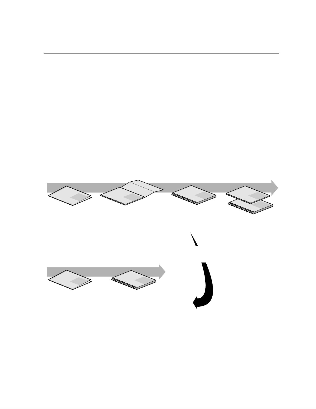
Using the Profile XP Documentation Set
This manual is part of a full set of support documentation for the Profile XP Media
Platform. The following illustrates how to use the Profile XP documentation
depending on the task you are performing.
Path for the Installer
Grass Valley Group
Profile XP
Manual
Family of XP Series
Release Notes
Contains the latest
information about Profile XP
hardware and software
shipped with your system.
Path for the Operator
Grass Valley Group
Profile XP
Manual
Family of XP Series
Release Notes
Contains the latest
information about Profile XP
hardware and software
shipped with your system.
Grass Valley Group
Profile XP
Manual
Family of XP Series
Installation Guide
Contains essential steps for
installing your Profile XP
system using factory
Grass Valley Group
System Guide
Contains the product description
and step-by-step instructions for
modifying system settings.
default settings.
Grass Valley Group
Profile XP
Manual
Family of XP Series
User Manuals
Contains complete instructions for using
Profile applications. These manuals include:
- Profile XP User Manual
- ContentShare Explorer User Manual
- Other user manuals you received with
Profile XP
Manual
Family of XP Series
Installers consult
the User Manuals
as needed.
Grass Valley Group
Profile XP
Manual
Family of XP Series
Grass Valley Group
Profile XP
Manual
Family of XP Series
Other Manuals
These manuals include:
- PFC500 Instruction Manu
- Profile XP Service Manua
with NetCentral.
0624-39
November 17, 2000 PFC500/E Instruction Manual 11
Page 12

Preface
Manual Descriptions
• Inst all atio n Guide (for your Profile XP Model) This guide provides step-by-step
instructio ns for installing the Profile XP Media Platform using factory default
settings fo r all record/play channels. Factory de fault settings are indicated within
the guide. After installing the Profile XP system using this installation guide, you
can refer to this Profile XP System Guide to customize system settings for your
installation.
•
Profile XP System Guide This guide provides al l t he inf or ma ti on yo u nee d to go
beyond factory defa ult settings an d customize your sys tem’s comfiguration to meet
your site-specific needs. This guide also provides an overview of your Profile XP
system, and provides all the spscifications you need to integrate the Profile XP
Media Platform into your operation.
•
Profile XP User Manual Contains complete instructions for using Profile
applications to operate the Profile XP Media Platform.
•
Profile XP Service with NetCentral Manual Contains information for servicing
the Profile XP Media Platform, and includes procedures for the following tasks:
- Problem analysis using symptom, problem, solution tables.
- Running diagnostics locally and remotely
- Set up and operation of Portals remote monitoring software.
- Replacing field replaceable units.
•
Profile XP Release Notes Contain s the latest inf ormation about the Profil e
hardware and the software release shipped on your system. This information
includes software specifications and requirements, feature changes from the
previous releases, helpful system administrative information, and any known
problems.
• PFC500/E Instruction Manual
Contains information f or servicing the Profile X P
Fibre Channel RAID Storage Chassis (PFC500/E) including step-by-step
procedures for replacing field replaceable units.
12 PFC500/E Instruction Manual November 17, 2000
Page 13

How this manual is organized
The PFC500/E Instruction Manual is organized around the tasks you’ll be
performing to install and service your Fibre Chann el RAID Storage Sys tem. You can
see this refl ected in the chap ter tit les chos en for t his man ual. The f ollowing i dentifi es
and describes the chapters included in this manual:
Chapter 1 - About the PFC500/E
Introduces the Profile XP Fibre Channel RAID Storage Chassis (PFC500) and the
RAID Expansion Chassis (PFC500E). You can read this chapter to get familiar with
the RAID Storage Chassis key features and components.
Chapter 2 - Installing a PFC500/E
Describes how to install a RAID Storage Chassis and RAID Expansion Chassis,
including rack mounting. Refer to the Profile XP System Guide for connection and
configuration information.
Chapter 3 - Servicing and upgrading a PFC500/E
Describes how to replace CRUs, such as disk modules , and add disk modules and
redundant CRUs.
Appendix A - Technical specifications and operating limits
This appendix consists of electrical and environmental specifications.
How this manual is organized
Glossary
The Glossary explains terms used throughout this manual.
November 17, 2000 PFC500/E Instruction Manual 13
Page 14

Preface
Getting more information
In addition to printed do cuments, Pro file XP product information is availabl e in
on-line manuals. Use these as additional sources for information.
On-line manuals
Electronic versions of the following manuals are located on the syst em dr i ve o f your
Profile XP Media Platform and on the Profile XP software CD-ROM.
• Installation Guide (for your model)
• Profile XP System Guide
• Profile XP User Manual
• Profile XP Service with NetCentral Manual
• PFC500/E Instruction Manual
• Profile XP Release Notes
You can view these manu als usin g Adobe Acroba t Reader whi ch is al so pre-in stalled
on your Profile XP system.
14 PFC500/E Instruction Manual November 17, 2000
Page 15

On-line manuals
Grass Valley Group Product Support
You can get technical assistanc e, c hec k on the status of pr obl ems, or report new problems b y
contacting our Product Support Group.
United States and Canada
Monday–Friday 5:30AM–5:00PM Pacific Time
(800) 547-8949
Europe
Monday–Friday 9:00AM–5:30PM
France 01 69 86 83 47 United Kingdom 01628 40583 0
Germany 0221 9477 446 Other +44 1628 405840
Italy 02 25086606
Asia and South America
Australia
- from overseas
Beijing 86-10-62351230
Brazil 55-11-3741-8422 Taiwan 886-2-27571571
Hong Kong 852-25856655
02-9888 0100
61-2-9888 0100
ext. 711
Japan 81-3-3448-3111
Korea 82-2-528-5299
Mexico 52-5-666-6333
Singapore 65-356-3900
World Wide
24-hour Emergency Hotline (530) 478-4148 (C ontr act and warranty customers)
World Wide Web http://www.grassvalleygroup.com
FTP Site ftp.grassvalleygroup.com
Users Group profile-users@grassvalleygroup.com
November 17, 2000 PFC500/E Instruction Manual 15
Page 16

Preface
16 PFC500/E Instruction Manual November 17, 2000
Page 17
Chapter
1
About the PFC500/E
This chapter introduce s the Pro file XP Fibr e Channel RAID Storage Chassis . Topics
are :
• PFC500/E components
• Enclosure
• RAID Controllers (RCs)
• Disk modules
• Power supplies
• Drive fan pack
• Configurations
The PFC500 is an intelligent, highly available, high performance, high capacity
storage system that uses a Fibre Channel Arbit rated Loop (FC-AL) as it s interconnect
interface. Its modula r, s calab le desi gn prov ides ad dit ional disk s torage as your needs
increase.
Using its FC-AL interface , with si mple FC-AL se rial cablin g, a PFC500 can support
up to two PFC500E RAID Expansion Chassis. A PFC500E is a basic chass is without
a RAID controller (RC). The PFC500 and two PFC500Es support up to 30 disk
modules in a single disk-array storage system. You can place the PFC500Es in the
same cabinet as the PFC500, in a separate cabinet, or in two separate cabinets.
A PFC500 connects to a Profile XP Media Platform using the server’s Fibre Channel
Disk adapter (FC adapter ).
Throughout this manual , t he term PFC500/E is used to refer to either the PFC500 or
the PFC 500E interchangeably.
November 17, 2000 PFC500/E Instruction Manual 17
Page 18

Chapter 1 About the PFC500/E
PFC500/E components
The PFC500/E components are:
• A sheet-metal chassis with a midplane and front door
• One or two RAID controllers (PFC500 only)
• One or two Link Control cards (PFC500E only)
• As many as ten Fibre Channel disk modules
• One or two power supplies
• One drive fan pack
Any unoccupied slot (RAID controller, disk module, or power supply) has a filler
module to maintain ai r flow and complian ce with electroma gnetic interfe rence (EMI)
standards.
The RCs, disk modules, power supplies, fan packs, and filler modules are
customer-replaceabl e units (CRUs), which you can add or replace without tools whi le
the PFC500/E is powered up.
The optional high availability features for a PFC 500/E are
• second RC (PFC500 only)
• second power supply
A second RC provides cont inued access to the PFC500 and any connected PFC500Es
if the first RC fails. Adding a second RC to the same chassis is not in tended to increase
performance, but ra ther to add re dundancy
detailed connection, configuration, and performance information.
The disk drives are FC-AL compliant and support dual-port FC-AL interconnects
through the two RCs and their cabling.
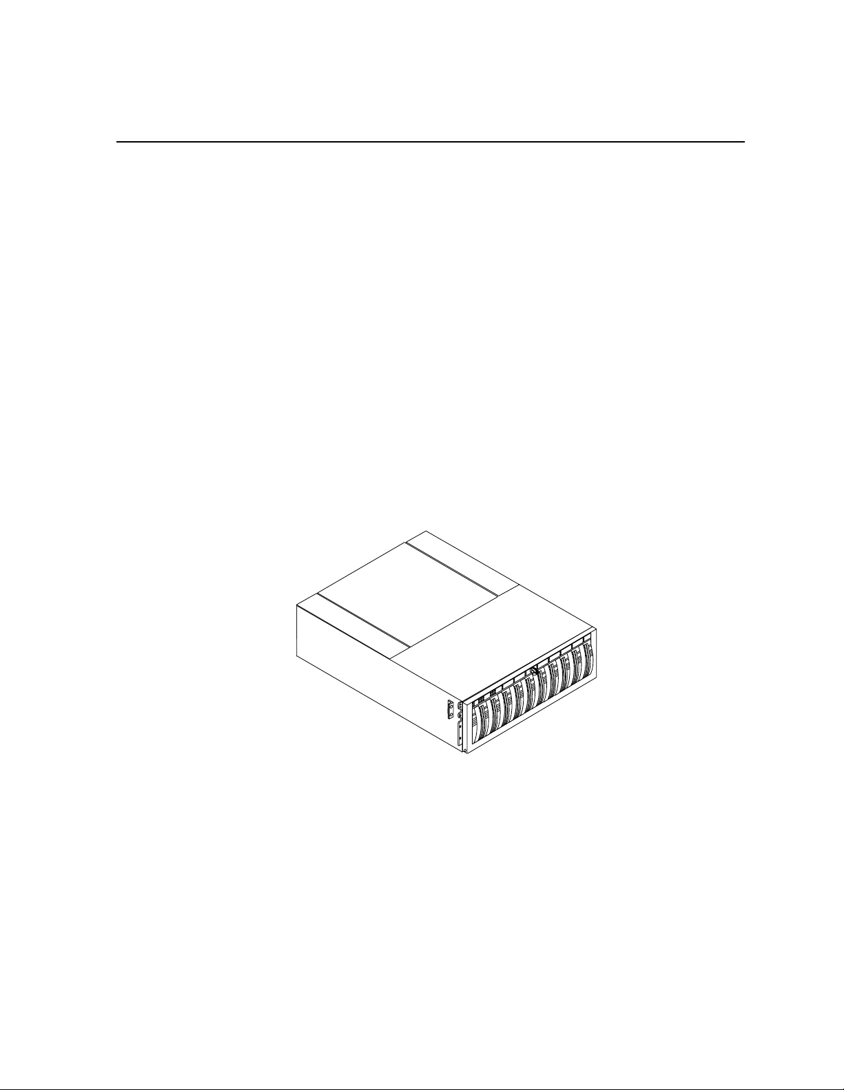
Chassis
The chassis is a sheet-metal housing with a front panel, a midplane, front door, and
slots for the RCs, disk modules, power supplies, and the fan pack.
The following figures show the PFC500/E components. Details on each component
follow the figures. If the chassis provides slots for two identical components, the
component in slot A is called component-name A. If there is a second component, it
is in slot B and is called component-nameB, as follows.
. Refer to the Profile XP System Guide for
Component Name in slot A Name in slot B
RAID Controller RC A RC B
Power supply PS A PS B
If you have one power supply, it can be in either slot A or slot B. If you have one
RAID controller, it can be in either slot A or B.
18 PFC500/E Instruction Manual November 17, 2000
Page 19
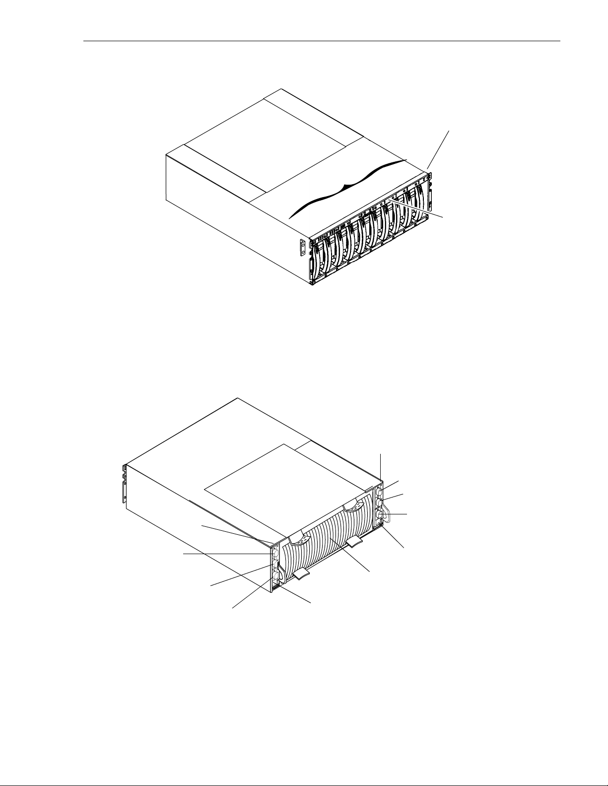
Front panel with door
removed for clarity.
*
s
e
l
u
d
o
m
k
s
i
D
n2
n1
n0
n3
n4
n5
n6
n7
n8
n9
* n is the chassis address (CA) set on the front panel at
installation. It must be set to 0 for a
values are invalid for a
PFC500. The disk module ID is the
PFC500. All other CA
chassis address and the module ID (0-9) within the chassis. In
PFC500, the ID for the right most disk module is 09.
a
Chassis
Front panel
Expansion (EXP) port
RC B
Port B
Port A
RC A
Expansion (EXP) port
E
X
P
Port B
A
B
Port A
E
X
P
A
B
Serial port
Drive fan pack
Serial port
November 17, 2000 PFC500/E Instruction Manual 19
Page 20
Chapter 1 About the PFC500/E
Power supply
in slot A
Power supply
E
X
P
in slot B
A
B
E
X
P
A
B
Power cord
connectors
Chassis
address lights
0
10
12345
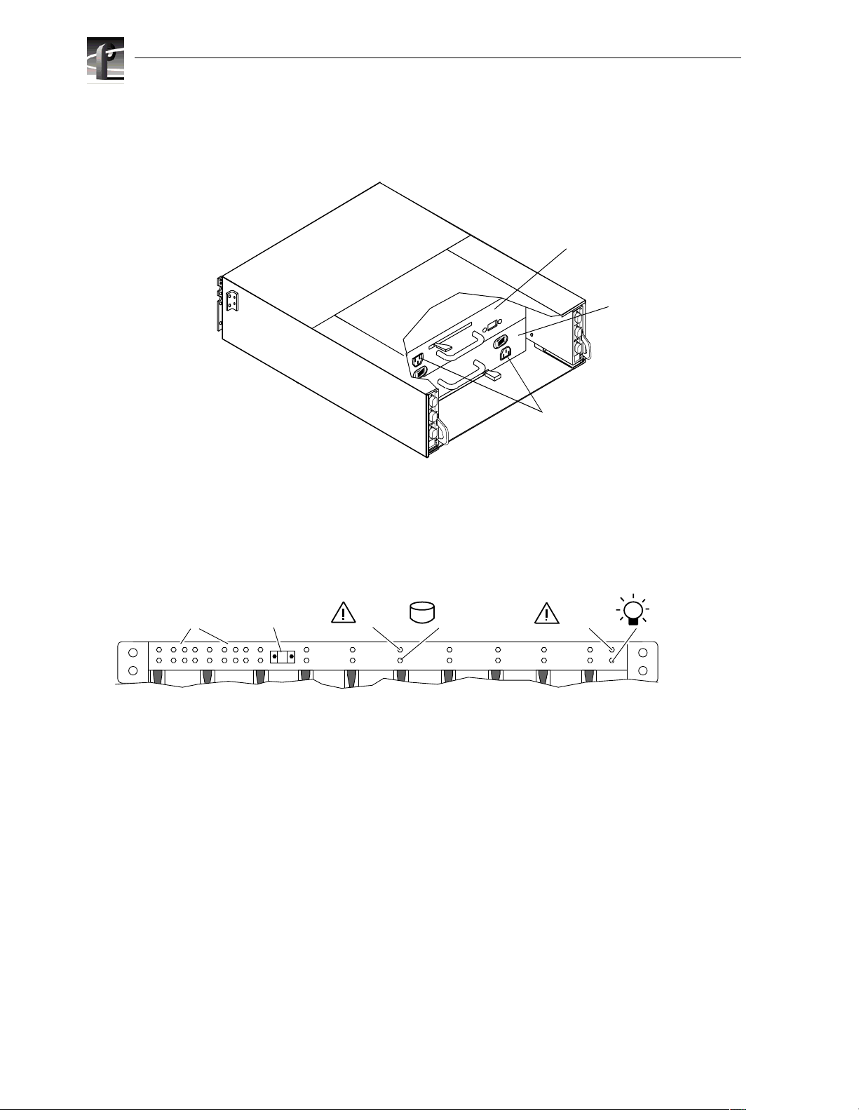
The front panel contains t he chassis address (CA) light, two status ligh ts for each disk
module slot, and two status lights. All lights are visible with the front door closed.
The chassis address light displays the chassis address setting for the PFC500. The
PFC500 must have a CA of 0. You must set that CA using the chassis address
switches, as explained in Chapter 2.
The status lights are described in the “Monitoring PFC500/E status” on page 42.
Midplane
The midplane distri but es power and signals t o a ll t he chassis components. All CRUs
except the fan packs plug directly into midplane connectors.
Disk module status lights
Chassis
address switch
(not visible with
door closed)
678910
0
2 3 4 5 6 7 8 9
11
(two per module)
Disk
check
Disk
Active
PFC 500/E status lights
System
Check
Power
20 PFC500/E Instruction Manual November 17, 2000
Page 21
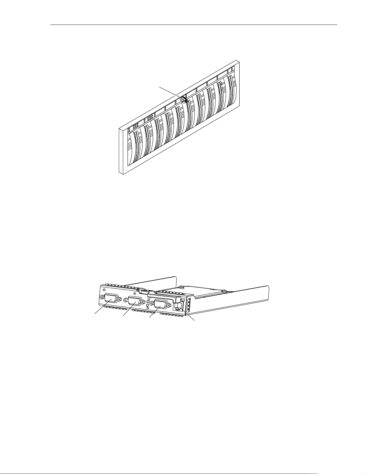
Front door
The front door has a loc king l atch a nd an EMI shiel d. The l atch i s a push button with
a removable locking key that you can use i n any PFC500 or PFC500E. When the door
is open, you can remove or install disk modules.
Front door
Locking latch
with key
IMPORTANT: The front door must be closed for the PFC500/E to be EMI
compliant. Opening the door to access the disk modules is a service procedure.
RAID Controllers (RCs)
The RC is the PFC500’s intelligent component. It defines the PFC500 and
differentiate s the
with one dual in-line memory module (DIMM), a bezel with status lights, and
securing latches.
E
X
P
expansion (EXP) port
The RC has three Fibre Channel ports. Port A and Port B are for connecting to a
Profile XP Media Platform. The expansion connector (EXP) is for connecting to a
PFC500E. The port interface is ca lled the RC front end. It can connect to a Profile XP
Media Platform’s Fibre Channel storage board. You set an RC’s FC-AL address ID
using rotary switches.
The RC connects to disk modules in the same chassis via an internal FC-AL. The
expansion port extends the internal FC-AL to the corresponding link control card
(LCC) in the PFC500E chassis. This FC-AL is referred to as the RC back end.
port B
PFC500 from a PFC500E. An RC is a printed-circuit board
B
port A
serial connection
An RC also has an RJ-type connector for serial communications with a console.
Each RC has two status light s visible from the rear of the PFC500/E. For the meaning
of these lights, see “Monitoring PFC500/E status” on page 42.
November 17, 2000 PFC500/E Instruction Manual 21
Page 22
Chapter 1 About the PFC500/E
Storage-system read caching requires one RC, and mirrored storage-system write
caching requires two RCs. If a PFC500 has one RC, you can install a second on e while
the PFC500 is running. When both RCs are ins talled, you can r eplace either RC whi le
the PFC 500 is running. You should never attempt to replace any of the RC’s
components, except the memory modules.
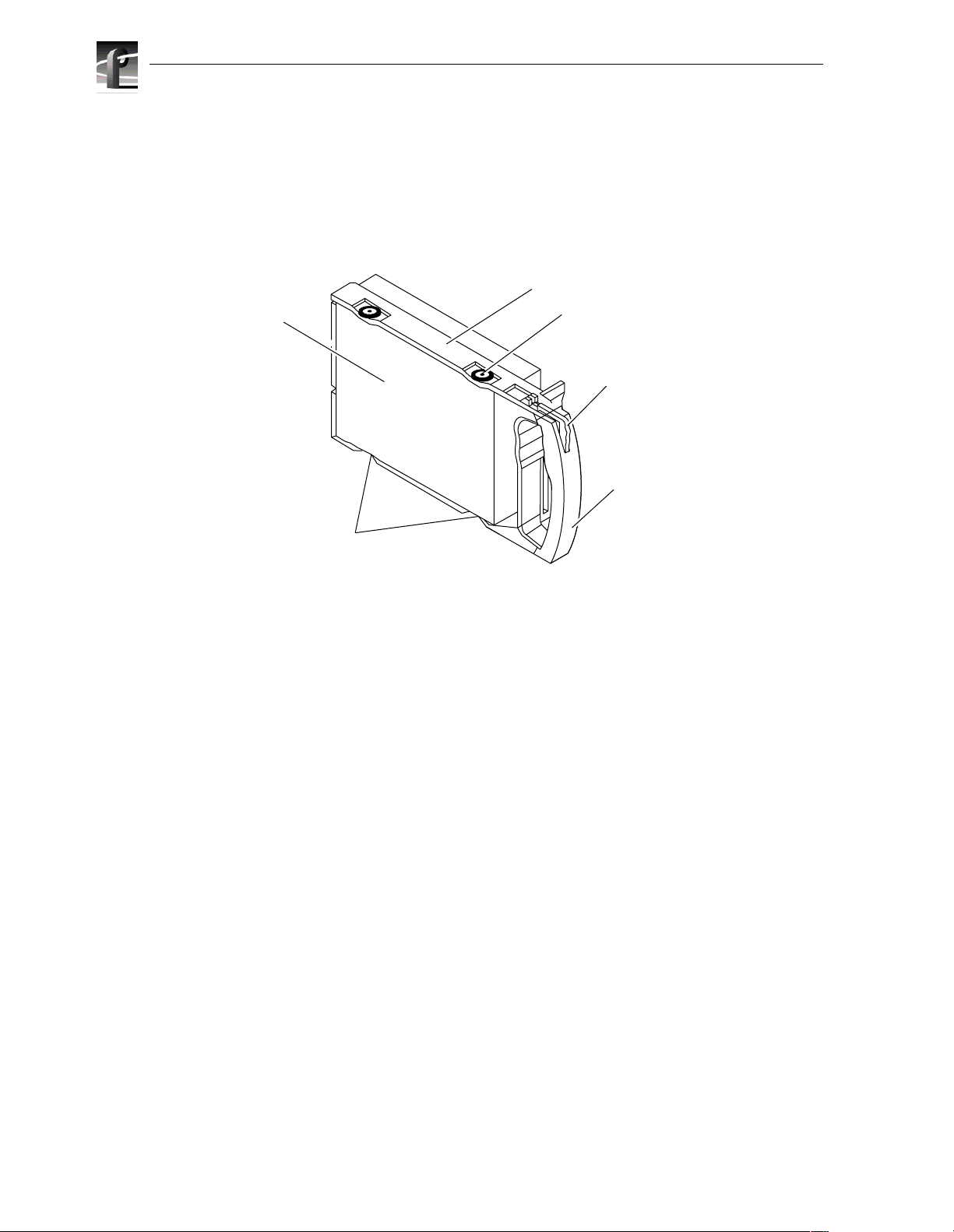
Disk modules
Disk drive
Carrier
Shock mount (4)
Latch
Handle
Each disk module consists of a Fibre Channel disk drive in a carrier assembly. You
can add or remove a disk module while the PFC500/E is powered up.
Disk drives
The disk drives are 3.5-inch FC-AL drives that conform to the following standards:
• SFF-8045
• Fibre Channel Arbitrated Loop (FC-AL)
• FC-AL Private Loop Direct Attach (PLDA) profile
The disk module slots in the chassis accommodate drives with heights of either
1.0 inch (2.54 cm) or 1.6 inches (4.06 cm). You can combine approved dr ives of either
height, and from different manufacturers, within the same PFC500/E, subject to the
restrictions imposed by the Licensed Internal Code (LIC) running in the PFC500’s
RCs.
Drive carrier
The disk-drive carr ier is a pl astic as sembly that s lides int o the chassi s slot gui des and
midplane connectors. It has a handle with a latch and electrostatic discharge (ESD)
clips, which connect to the drive’s head-disk assembly. The latch holds the disk
module in place to ensure proper connection with the midplane.
ESD clip (2)
22 PFC500/E Instruction Manual November 17, 2000
Page 23
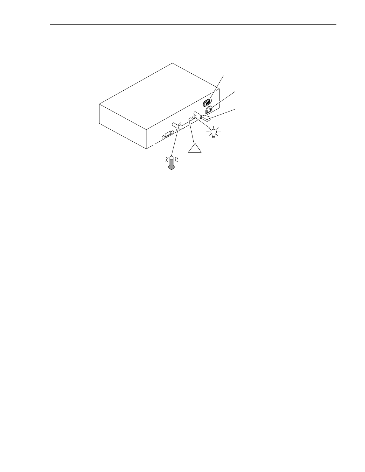
Power supplies (PSs)
The power supplies are located behind the drive fan pack. With two power supplies,
the top supply is installed inverted with respect to the bottom supply.
Each power supply is an auto-ran ging, power -factor-c orrected , multi-outp ut, off-li ne
converter with its own line cord and on/off switch. Each supply supports a fully
configured PFC500 and shares load currents with the other supply, if it is present. The
drive voltage lines have individual soft-start switches that protect the disk drives if
you install them whil e the PFC500/E is powered up. A disk with power-rela ted faults
will not adversely affect the operation of any other disk.
On/Off switch and
circuit breaker
Check light
!
(amber)
Cooling Check
light (amber)
Power supplies (PSs)
Ac line cord
connector
Latch
Active light
(green)
Each power supply has status lights. These status lights are partially visible through
the drive fan pack, and fully visible wi th the drive fan pack removed. The s tatus lights
are described in the “Monitoring PFC500/E status” on page 42.
A latch on the power supply locks it into place to ensure proper connection to the
midplane. You can add or remove on e power supp ly in a hig hly avai lable PFC500/E
while the PFC500/E is powered up.
November 17, 2000 PFC500/E Instruction Manual 23
Page 24
Chapter 1 About the PFC500/E
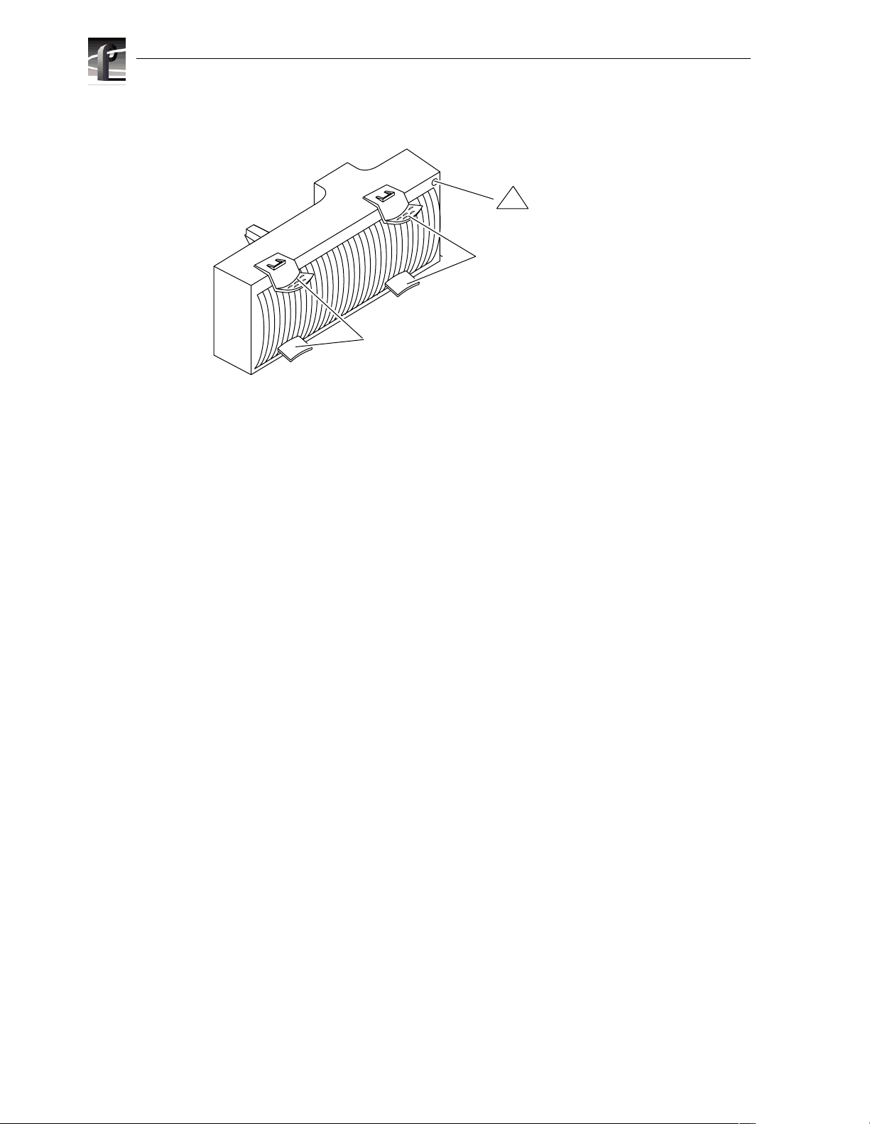
Drive fan pack
The drive fan pack cool s the disk modules and RCs in the PFC500. The drive fan pac k
contains three fans tha t draw ambient room air throug h the front door, across th e drive
modules, and through t he midpl ane and p ower supp lies. The dr ive f an pack c onnect s
directly to both power supplies, and ei the r s uppl y c an power it. The fans ope rat e a t a
lower voltage and speed durin g normal ope ration to min imize acoust ic noise. If a fan
fails, the voltag e and speed of the remaining fans increase to c ompensate, resul ting in
higher acoustic noise.
Check light
(amber)
!
Latches
Latches
One status light on th e dri ve fan pack i ndica te s sta tus. The stat us li ght i s desc ribed in
the “Monitoring PFC500 status” section of Chapter 3.
Latches on the drive fan pack hold the pack in place.
IMPORTANT: You can remove the drive fan pack while the PFC500 is powered
up. While the pack is removed, the Cooling Check light on each power supply
flashes. If the pack is removed for more than approximately two minutes, the disk
modules power down and the RCs go into standby mode. When you re-install the
drive fan pack, the disk modules power up and the RCs go into active mode.
24 PFC500/E Instruction Manual November 17, 2000
Page 25

Configurations
The PFC500 minimum and maximum configurations are as follows.
Configuration RCs Power Supplies Disk Modules
minimum 1
maximum 2 2 10
The maximum configurati on provides the most redundancy, and theref ore the highest
degree of system availability. The fan pack provides redundant cooling for any
configuration.
IMPORTANT: Grass Valley Group does not supp ort mixing disk drives of differing
capacities in any RAID c hassis connected to a Pr ofi le XP medi a platform. All disk
drives in any RAID chassis connect ed to a Profile XP media platform must be of the
same capacity. For example, if a PFC500 and a PFC500E are connected to a
Profile XP system, all the disk drives in both the PFC500 and the PFC500E must
be of the same capacity.
What next?
Configurations
1
2
1
5
5
Continue to the next chapter, which te lls how to install a PFC500/E.
November 17, 2000 PFC500/E Instruction Manual 25
Page 26

Chapter 1 About the PFC500/E
26 PFC500/E Instruction Manual November 17, 2000
Page 27

Chapter
2
Installing a PFC500/E
This chapter describes t he Profile XP Fibre Channel RAID Storage Chassis (PFC500/E)
installation requirements and procedures. Major topics are:
• Requirements
• Rack mounting a PFC500/E
• PFC500/E powerup and initialization
• PFC500/E powerdown
• Binding disk modules into groups
Requirements
This section explains site, cabling, and addressing requirements.
Site requirements
For proper PFC500/E operation, the installation site must conform to certain
environmental specifications. These are detailed below and in Appendix A.
Power
Cooling
To determine a PFC500/E’s power requirements, use the power rating on the chassis
label. This rating is the maximum power required for a fully loaded chassis. The input
current, power (VA), and dissipation for the PFC500/E are based on the maximum
capability of the power supplies and cooling system to provide internally regulated
power. Typical values will be less depending on the number and manufacturer of disk
drives and activity level. These values represent either the values for the power cord of
a PFC500/E with a single power supply, or the total values shared by the line cords of
two power supplies in the same PFC 500/E, with the division between the power cords
and supplies at the current sharing ratio. If one of the two power supplies fails, the
remaining supply and cord suppo rt the full load. You must use a rack mou nt cabinet with
ac power distribut ion, and have mai n branch ac dist ributio n that c an handle these values
for the number of PFC500s and PFC500Es that you will interconnect.
The ambient temperature spe cificat ion is measured at the front door in let. The site must
have air condit ioning of the correct siz e and placement to maintain the specified ambient
temperature range. The air conditioning mus t be able to handle the BTU requirements o f
the PFC 500s and any connected PFC500Es.
November 17, 2000 PFC500/E Instruction Manual 27
Page 28

Chapter 2 Installing a PFC500/E
Cabling requirements
You mst use copper cables for the FC-AL connections between the RCs and the server
adapters or hubs. You should use a common ground distribution grid for all
interconnected devices.
IMPORTANT: You must use a copper cable on ly (not an o pti cal cable) to connect
a PFC500 to a PFC500E.
Any copper cables you use must meet the appropriate standards for 1-Gbaud FC-AL
loops. Such cables are fully shielded, twin-axial, full-duplex cables with DB-9
connectors. Cables gr eater than 10 meters must be equalized; ca bles equal to or les s than
10 meters do not need to be equalized.
PFC500 and PFC500E interconnections should maint ain LCC consistency. That is, one
FC loop should conne ct the PFC500’s RC A and each PFC500E’s LCC A. The other FC
loop should connect the PFC500/E’s RC B and each PFC500E’s LCC B.
Do not leave an unused ( that is , dangling) cable conn ected to a n RC port beca use it may
cause excess noise on the loop.
Addressing requirements
There are two addresses for the PFC500: the Fibre Channel Arbitrated Loop add ress ID
(FC-AL address ID) and the chassis address.
FC-AL address ID
Each node (such as an RC) on the Fibre Channel front-end loop must have a unique
FC-AL address ID. The FC-AL protocol translates the FC-AL address ID into an 8-bit
arbitrated loop physical address (ALPA). You set the RC FC-AL address ID using
switches, as expla ined later in t his chapter . If your PFC500 has a second, redundant RC,
it should be set to a different FC-AL address ID than the primary FC.
Chassis address (CA)
Each PFC500 and PFC500E on a back-end loop needs a unique chassis address (CA)
that identifies the chassis and determines disk module addresses . The PFC500 must have
a CA of 0. You must set that CA using the chassis address switches, as explained later
in this chapter. If you cable any PFC500Es to the PFC500, you might want to set the
nearest PFC500E’s CA to 1, and the next to 2. The chassis a ddress is displayed in light s
visible behind the front door.
28 PFC500/E Instruction Manual November 17, 2000
Page 29

Installing a PFC500/E in a cabinet
Installing a PFC500/E in a cabinet
The cabinet in which you will insta ll the PFC500/E(s) must have a full earth ground to
provide reliable grounding. Also, the cabinet should have its own switchable power
distribution. If any PFC500/E you will install has two power supplies, we suggest that
you use a cabinet that has dual power distribution units, one on each side.
>>> WARNING: The rack mount PFC500/E is heavy and should be installed into a
rack by two people. To avoid personal injury and/or damage to the equipment, do
not attempt to lift an d ins ta ll the PFC500/E into a rack without help from ano the r
person.
We recommend that you use cabinet anti-tip devices, especially if you are installing or
removing a PFC500/E in the upper half of the cabinet when the lower half is empty.
You install each PFC500/E on two L-shaped mounting rails connected to the cabinet’s
vertical channels. The PFC500/E mounting rails attach to the cabinet only, and do not
have components which attach to the RAID chassis.
Rack-mounting the PFC500/E chassis consists of:
1. Determining the rail mounting positions in the cabinet.
2. Attaching the mounting rails to the cabinet.
3. Sliding the PFC500/E chassis onto the mounting rails.
4. Setting addresses and connecting cables.
The following sections describe these operations.
Determining the rail mounting positions
The following table lists the heights of the PFC500 and the PFC500E. Use these
measurements to determine the position of your RAID devices in your cabinet.
Device Height
PFC 500 RAID Storage
Chassis
PFC 500E RAID Expansion
Chassis
NOTE: Because the RAID storage units are eac h 3.5 U high, a 0.5 U open space is
created if you install one of these units immediately below your Profile XP Media
Platform. You can fill this gap with a 1/2 U filler, which attaches to the chassis, not
to the cabine t channels.
3.5. U, 6-1/8 in,
15.6 cm
3.5. U, 6-1/8 in,
15.6 cm
Number of cabinet
channel holes,
starting U-aligned
10
10
November 17, 2000 PFC500/E Instruction Manual 29
Page 30

Chapter 2 Installing a PFC500/E
The following illustration shows the baselines of different devices in a cabinet.
6.5U
6U
5U
4U
3.5U
3U
2U
1U
1/2in
5/8in
5/8in
1/2in
5/8in
5/8in
1/2in
5/8in
5/8in
1/2in
5/8in
5/8in
1/2in
5/8in
5/8in
1/2in
5/8in
5/8in
1/2in
5/8in
5/8in
1/2in
Pre drilled holes for
rail installation
3.5U device
1U device
Baseline of next device
Baseline of next device
6.5U device
Baseline of next device
Baseline of device at a
U-aligned position, between
two holes 1/2in apart.
Review your plan to make sure all devices will fit in the cabinet and also review any
requirements for filler panels.
30 PFC500/E Instruction Manual November 17, 2000
Page 31

Attaching the mounting rails
Once you have determined the positions for the mounting rails, you can attach them to
the cabinet. Each rail has threaded nuts on its front flange. You can install any rail in a
U-aligned or U-nonaligned position.
1. For each device, attach the rails to the front channels as follows.
Attaching the mounting rails
DPE rails
Baseline
A. Align the base of the left rail with the
baseline and use two screws to
attach the front of the left rail loosely
to the cabinet’s front channel.
Baseline
B. Align the base of the right rail with
the baseline and use two screws to
attach the front of the right rail
loosely to the cabinet’s front channel.
November 17, 2000 PFC500/E Instruction Manual 31
Page 32

Chapter 2 Installing a PFC500/E
2. Attach the rails to the middle channel, as shown next.
A.
Push the rail away from the middle channel and slide clip nuts onto the
channel, into the channel holes that align with the rail holes. The
surface of the channel you use depends on the type of rail.
B.
Use two screws to fasten the back of the rail to the clip nuts.
Middle channel,
view from front
of cabinet
C.
Tighten all screws that fasten the rails to the channels.
If you want to use one or more filler panels for esthetic purposes, attach them after
installing the devices in the cabinet.
Sliding PFC500/E onto rails
To install PFC500/Es on the mounting rails in the cabinet
1. Attach th e clip of the ESD wristband (strap) to bare metal on the cabinet, and put
the wristband around your wrist with the metal button against your skin.
2. Lift the PFC500/E, and from the front of the cabin et, sl ide the PFC500/E onto the
lowest rail s. Brackets on the rear of the rails fit into cutouts on the PFC500/E.
Middle channel,
view from front
of cabinet
32 PFC500/E Instruction Manual November 17, 2000
Page 33

3. Open the PFC500/E front door as shown here.
CAUTION: Do not force the door open.
If the door snaps off the hinges, re-install it by positioning it at a
o
angle to the chassis and snapping it into the hinge openings.
45
Latch
Key
Latch
Sliding PFC500/E onto rails
If the door is locked
• Insert the key in the door’s latch.
• Turn the key 180
• Remove the key, if desired. (If you
do not remove the key, it may fall
to the floor after you open the
door.)
• Press the door latch.
• Lower the door until it is perpendi cular
to the font of the chassis.
o
clockwise.
4. Secure the PFC500/E to the vertical channels of the cabinet as shown here.
Fasten the front of the enclosure to
the front mounting holes in the cabinet
using two screws (one per side)
NOTE: Only one hole in the chassis bracket aligns with
a mounting hole on the cabinet. The mounting hole you
use depends on where the rails are mounted in the cabinet.
November 17, 2000 PFC500/E Instruction Manual 33
Page 34

Chapter 2 Installing a PFC500/E
5. Close the PFC500/E front door, as shown here.
IMPORTANT: The door must be closed for EMI compliance. Open the door only
to service the PFC500/E.
A. Raise the door until it
latches into place.
B. If desired, lock the door as follows:
• Insert the key into the door latch.
• Turn the key 180
• Remove the key, if desired.
o
counterclockwise.
Latch
Latch
Key
34 PFC500/E Instruction Manual November 17, 2000
Page 35

Setting addresses and connecting cables
Setting addresses and connecting cables
You must now set FC-AL address ID on the RAID controllers, set the chassis ID,
connect Fibre Channel cables, and connect power cables. Refer to the Profile XP System
Guide for the settings required for your installation.
1. At the back of the PFC500 chassis, remove each RC f rom its slot as s hown below.
Latch up
P
X
E
A
B
A. Pull up the latch on the RC.
EXP
A
B
B. Grasp the RC and gently
pull it out of the slot
2. For each RC, set the FC-AL address ID using the FC-AL ID switches on the RC
printed circuit board.
Each node (such as an RC) on a Fi bre Channel front-end loop mu st have a unique
FC-AL address ID. The FC-AL protocol translates the FC-AL address ID into an
8-bit arbitrated loop physical address (ALPA).
IMPORTANT: Each RC’s FC-AL ID must be unique from all other FC devices on
that same FC-AL loop.
When using redundant RCs, set the FC-AL ID on the RCs for all PFC500s
connected as indicated in the following table.
Number of
PFC500s
1First 0 1
2First
PFC500
chassis
Second
Primary RC’s
FC-AL ID
0
1
Redundant
RC’s FC-AL ID
2
3
3First
Second|
Third
0
1
2
3
4
5
November 17, 2000 PFC500/E Instruction Manual 35
Page 36

Chapter 2 Installing a PFC500/E
The valid FC-AL address ID range is a number 0 through 125 decimal, whi ch is 0
through 7D hexadecimal. The following figures and table locate the switches and
show how to select ID numbers using them.
E
X
P
RC FC-AL address ID switches
B
For address ID Set top switch to Set bottom switch to
00 0
10 1
.
.
.
15 0 F
16 1 0
.
.
.
29 1 D
Location of switches
.
.
.
.
.
.
.
.
.
.
.
.
3. Set the PFC500’s chassis address (CA) switch to 0 using t he tip of a pen or a paper
clip as shown in the following illustration.
To access the CA switch, you must open the PFC500/E’s front door. The chassis
address, referred to as the back-end address, identifies the PFC500/E and
determines disk module addresses. The PFC500 chassis address must be set to 0.
00
1
2
3
4
5
123
6
7
8
9
10
11
0
Chassis
address lights
Decrement button
Push to decrease address.
Increment button
Push to increase address.
Address
switch
0
NOTE: The address
switch has 16 positions, 12 are marked
0 through 11 and the
remaining 4 are
marked with a dash
(-). A dash position
is equivalent to the 0
position.
36 PFC500/E Instruction Manual November 17, 2000
Page 37

4. Reinstall each RC in its slot as shown below.
A. Pull up the latch on the RC.
B. Align the RC with the guide on the slot.
C. Gently slide the RC into the slot.
EXP
A
B
EXP
Setting addresses and connecting cables
Latch up
A
B
5. Remove the drive fan pack as shown below.
E
X
P
A
B
A. Grasp the latches on the drive fan pack.
B. Squeeze the latch es to get her an d p ul l the
fan pack from the chassis.
D. Push dow n the latch until
the RC is fully seated in
the slot.
Latch down
November 17, 2000 PFC500/E Instruction Manual 37
Page 38

Chapter 2 Installing a PFC500/E
6. From the ba ck of the cabin et, plug the ac line cord in to each power su pply and tur n
on the supply’s power, as shown next.
ac inlet
Bottom power supply
E
X
P
A
B
ac inlet
Power switch and
circuit breaker
Top power supply
E
X
P
A
B
Channel
B
A
P
X
E
Channel
ac power cord
B
A
P
X
E
(right-angle plug)
ac power cord
(right-angle plug)
Power switch and
circuit breaker
For each power supply:
A. Insert the right-angle plug on the ac line cord into the supply’s ac inlet
B. Route the cord along the power supply to the side of the chassis.
IMPORTANT: The cord must not occupy the drive fan pack space.
C. Bend the cord into a U shape and slide the U into the channel so the end of
the cable comes out of the channel at the back of the chassis.
D. Plug the end of the cord into one of the cabinet’s power outlets.
E. Set the supply’s power switch to the on (1) position.
7. Re-install the drive fan pack in the back of the PFC500/E.
You can install the drive fan pack in either horizontal position. However, for a
consistent image with a ll PFC500/Es, we recommend you install it with the status
light in the upper right corner as shown below.
A. Grasp the latches on the
drive fan pack.
B. Squeeze the latches
together and gently push
the fan pack into the
E
X
P
A
B
chassis until it clicks in
place.
38 PFC500/E Instruction Manual November 17, 2000
Page 39

Setting addresses and connecting cables
8. Attach the Fibre Chann el cable from t he Profile XP Media Plat form Fibre Chan nel
Disk board to the RC’s A port. Use a copper cable as shown here
IMPORTANT: Do not leave an unused (that is, dangling) c able connected to an RC
port because it may cause excess noise on the loop.
EXP
A. Plug the copper cable from the
Profile XP Media Platform Fibre
Channel Disk board into po rt A on the
EXP
A
B
EXP
A
B
Port B
A
Port A
B
RC.
B. Tighten the two screws on each
cable connector.
RJ-style connector for
serial connection to an
RCS or a console
To server, hub, or other FC device
9. To expand this PFC500, cable its EXP connector to the correspond ing PFC500E’s
PRI (primary) connector as shown here.
IMPORTANT: Do not connect a cable between
an RC in slot A and any L CC in slot B or between
an RC in slot B and any LCC in slot A.
A. Plug one end of the copper cable
onto the expansion (EXP)
EXP
A
B
PRI
EXP port
connector on the RC in the
PFC 500/E.
B. Tighten the two screws on the
cable’s connector.
EXP
C. Plug the other end of the copper
cable into the primary (PRI)
connector on the LCC in the
A
PFC500E.
D. Tighten the two screws on the
cable’s connector.
10.If the PFC500 has another RC and PFC500Es , connect the PFC500’s other RC and
the PFC 500E’s other LCCs as above.
November 17, 2000 PFC500/E Instruction Manual 39
Page 40

Chapter 2 Installing a PFC500/E
11.To connect additional PFC500Es, attach a copper cable between the PFC500E’s
LCC EXP connector and the next PFC500E’s PRI (primary) connector. If this
PFC500E and the next PFC500E have a second LCC, repeat this step for the
second LCC.
12.Make sure all the slo ts in the PFC500 and each PFC500E contain either CRUs or
filler modules. At least three disk modules (in slots 0, 1and 2) are required in the
PFC500.
13.In the cabinet, set the main circuit breaker switches to the on position.
The PFC500 and any PFC500Es in the cabinet will power up.
PFC500/E powerup and initialization
The only power switches on a PFC 500/E are those on the power supply, which are
normally covered by the drive fan pack. As a result, a PFC500/E is always active.
When ac power is initially applied to a PFC500/E, the disk drives power up according
to their specifications, and spin up in a specified sequence. The slot spin-up delays are
multiples of 12 seconds. The maximum delay is 84 seconds. The same delays are used
when you insert a drive while a PFC500/E is powered up.
NOTE: Upon powerup, all LUNs are controlled by RAID Controller A if it is
operational. RC B controls LUNs onl y if RC A fails, and continue s to control LUNs
until the next powerup.
PFC500/E powerdown
To turn off power correctly
1. Stop any I/O activity to the PFC500/E.
2. Shut off power to the ac distribution strips that supply the PFC500/E.
The power in the distribution strips ma y be co ntr o l le d by a circuit breaker l oca ted
inside the cabinet (if the cabinet has such breakers) or may be controlled by a
circuit breaker located externally to the cabinet.
To turn on power, reverse the steps to powerup the PFC 500/E.
Binding disk modules into groups
After cabling a PFC500/E and any PFC500Es, you must bind disk modules into LUNs
and create a file system using the Profile XP Disk Utility. Refer to the Profile XP System
Guide for more information on configuring your storage system.
40 PFC500/E Instruction Manual November 17, 2000
Page 41

Chapter
3
Servicing and upgrading a PFC500/E
This chapter describes how to monitor PFC500/E status, handle CRUs, and replace
or add a CRU. Topics are
• Hot swapping components
• Monitoring PFC500/E status
• Handling CRUs
• Replacing or adding a disk module
• Replacing all disk modules in a PFC500/E
• Removing an RC or an RC filler module
• Installing or removing the RC memory module
• Installing an RC or RC filler module
• Replacing the drive fan pac k
• Replacing or adding a power supply
Hot swapping comp onents
The PFC500/E is designed for co ntinuous operation, and it should always be p owered
up. You can replace any disk module, redundant RC, or fan pack while the PFC500/
E is running.
During normal PFC500/E operation, all compartments s hould contain either a modul e
or filler, and t he front door s hould be closed. Th is ensures EMI complia nce and proper
air flow (cooling) within the unit.
The following CRUs are available from Grass Valley Group.
Description Part Number
18GB replacement drive PFC18G
36GB replacement drive PFC36G
RAID Controller (RC) 039-0084-XX
Link Controller Card (LCC) 116-0942-XX
Power supply 119-6314-XX
Fan module 119-6315-XX
Rackmount kit 016-1863-00
Fibre Optic Cable, PFC500 to PFC500E 174-4409-00
November 17, 2000 PFC500/E Instruction Manual 41
Page 42

Chapter 3 Servicing and upgrading a PFC500/E
Monitoring PFC500/E status
Status lights on the PFC500/E and its CRUs indicate error conditions. Thes e lights are
visible outsid e the PFC500/E. Some lights are visibl e from th e front, and ot hers fr om
the back. The following figure and table describes the status lights.
IMPORTANT: The PFC500 chassis address must be set to 0 (zero)
Disk module status lights
(two per module)
Disk
check
Disk
Active
Chassis
address lights
0
10
12345
Chassis
address switch
(not visible with
door closed)
678910
0
2 3 4 5 6 7 8 9
11
.
PFC 500/E status lights
System
Check
Power
Light Quantity Color Meaning
PFC500/E Power
PFC500/E System
1Green
On when the PFC500/E is powered up.
1 Amber On when any fault condition exists.
Check
Disk Active 1 per disk
module slot
Green Off when the disk module slot is empty or
contains a filler module.
Flashing (mostly off) when the drive is
powered up but not spinning; this is a
normal part of the spin
-up sequence,
occurring during the spin -up delay of a slot.
Flashing (at a const ant rate) when the disk
drive is spinning up or spinning down
normally.
On when the drive is spinning but not
handling any I/O activity (the ready state).
Flashing (mostly on ) when the disk drive is
spinning and handling I/O activity.
Disk Check 1 per disk
module slot
Amber On when the disk module is faulty, or as an
indication to remove the drive.
Chassis Address 12 Green The chassis ad dress for the PFC500 must
be set to 0 (zero), the only chassis
address that is valid for the PFC500.
42 PFC500/E Instruction Manual November 17, 2000
Page 43

Monitoring PFC500/E status
Status lights visible at the back of the PFC500/E
Light Quantity Color Meaning
Active 1 per RC Green On when the RC is powered up.
RC Check 1 per RC Amber On when either the RC or a Fibre Channel
connection is faulty.
Power Supply Active 1 per supply Green On when the power supply is operating.
Power Supply Check 1 per supply Amber On when the power supply is faulty or is
not receiving ac line voltage.
Cooling Check 1 per supply Amber Flashing when either multiple fans in the
drive fan pack are faulty or the drive fan
pack is removed. The RC powers down
the disk drives and goes into standby
mode when the fault persists for more
than about two minutes.
Drive Fan Pack Check 1 on drive
fan pack
If the RC Check light is on, you should look at the other Check lights to determine
which CRU is faulty. If a check light on a CRU remains on, you should replace that
CRU as soon as possible.
Yellow On when a fan in the drive fan pack is
faulty.
If a non-redundant CRU fails in a PFC500, the system may be inoperable while you
replace the CRU. If a redundant CRU fails, high availability will be compromised
until you replace the faulty CRU.
November 17, 2000 PFC500/E Instruction Manual 43
Page 44

Chapter 3 Servicing and upgrading a PFC500/E
Handling CRUs
This section describes the pre cauti ons that you must tak e and the genera l procedu res
you must follow when removing, installing, and storing CRUs.
Power issues and CRUs
The PFC500/E is designed for continuous operation and to be hot repairable . It should
always be powered up. You should replace any disk module, redundant RC,
redundant power supply, or the fan pack while the PFC500/E is running.
Its front door sh ould be clos ed and each o f its compar tments shoul d contain a CRU or
filler panel to ensure EMI compliance and proper air flow over the CRUs.
While the PFC500/E is powered up, you can service or replace any CRU. You should
not remove a faulty CRU until you have a replacement available.
IMPORTANT: You can remove the drive fan pack while the PFC500/E is powered
up. While the pack is removed, the Cooli ng check light on the power supply flashes.
If the pack is removed f or mor e t han 2 minut es, the disk modules power do wn and
the each RC goes into standby mode . When you reinstall the drive f an pack, the disk
modules power up and each RC goes into active mode.
Since you can replace or add any CRU without sliding the PFC500/E out of the
cabinet, you do not have to use cabinet anti-t ip de vi ces wh en yo u upgr ad e or service
a PFC500/E.
If you need to power down a PFC500/E, refer to “PFC500/E powerdown” on page 40.
Avoiding electrostatic discharge (ESD) damage
When you replace or install CRUs, you can inadvertently damage the sensitive
electronic circui ts in the equipment by si mply touching them. Electr ostatic charge that
has accumulated on your body discharges through the circuits. If the air in the work
area is very dry, running a humidifier in the work area will help decrease the risk of
ESD damage. You must follow the procedures below to prevent damage to the
equipment.
IMPORTANT: Read and understand the following instructions.
• Provide enough room to work on the equipment. Clear the work site of any
unnecessary materi als or materials th at naturally buil d up electrostati c charge, such
as foam packaging, foam cups, cellophane wrappers, and similar items.
• Do not remove replacement or upgrade CRUs from their anti static packagin g until
you are ready to install them.
• Gather together the ESD kit and all other materials you will need before you
service a PFC500/E. Once servicing begins, you should avoid moving away fr om
the work site; otherwise, you may build up an electrostatic charge.
• Use the ESD kit when handling any CRU. If an emergency arises and the ESD kit
is not available, follow the procedures in the “Emergency procedures (without an
ESD kit)” section.
44 PFC500/E Instruction Manual November 17, 2000
Page 45

Precautions when removing, installing, or storing
• To use an ESD wristband, attach the clip of the ESD wristband (str ap) to any bare
(unpainted) metal on the PFC500/E chassis; then put the wristband around your
wrist with the metal button against your skin.
Emergency procedures (without an ESD kit)
In an emergency when an ESD kit is not available, use the following procedures to
reduce the possibi lity of an ele ctrostatic di scharge by e nsuring that your body and the
subassembly are at the same electrostatic potential.
IMPORTANT: These procedures are not a substitute for the use of an ESD kit.
Follow them only in the event of an emergency.
• Before touching any CRU, touch a bare (unpainted ) metal surface of the cabinet o r
chassis.
• Before removing any CRU from its anti stat ic ba g, pla ce one hand firml y o n a ba re
metal surface of the chassi s, and at the sa me time, pi ck up the CRU while i t is s till
sealed in the antistat ic bag. Once you have done this, do not move around the room
or contact other furnishings, personnel, or surfaces until you have installed the
CRU.
• When you remove a CRU from the antistatic bag, avoid touching any electronic
components and circuits on it.
• If you must move around the room or touch o ther surfaces before instal ling a CRU,
first place the CRU back i n the antistatic bag. When you are ready again to i nst al l
the CRU, repeat these procedures.
Precautions when rem ov in g , inst a ll ing , or st or ing CRUs
Use the precautions listed below when you remove, handle, or store CRUs.
• Do not remove a faulty CRU until you have a replacement available.
• Handle a CRU only when using an ESD wristband as follows: attach the clip of the
ESD wristband to the ESD bracket or bare metal on the PFC500/E chassis, and put
the wristband around your wrist with the metal button against your skin.
• Handle CRUs gently. A sudden jar, drop, or vibration can permanently damage a
CRU.
• Never use excessive force to remove or install a CRU.
• Store a CRU in the antistatic bag and specially designed shipping container in
which you received it. Use tha t container if yo u need to return the CRU for repair.
• Maintain the location where you store CRUs within the limits specified in
Appendix A.
November 17, 2000 PFC500/E Instruction Manual 45
Page 46

Chapter 3 Servicing and upgrading a PFC500/E
Replacing or adding a disk module
IMPORTANT: Grass Valley Group does not support mixing disk drives of differing
capacities in any RAID c h ass is co nnect ed to a Profile XP media pla tf orm. Al l disk
drives in any RAID chassis conn ected to a Profile XP media platfo rm must be of the
same capacity. For example, if a PFC500 and a PFC500E are connected to a
Profile XP system, all the disk drives in both the PFC500 and the PFC500E must
be of the same capacity.
>>> CAUTION: You can destroy a storage system beyond recovery if you move the
wrong drive. The system operator or service person can move a disk module with
the followin g cautions:
• The disk module must be unbound.
• Moving a module that is part of a LUN to another slot makes all information on the
LUN inaccessible.
• You must remove and install the disk module while the storage system is powered
up.
A disk module must be inserted all the way or removed entirely. Do not leave a disk
module partially removed except for periods when you are allowing it to spin down.
A disk module being inserted or removed may be damaged by a partially removed
adjacent module.
When replacing multiple disks, observe the following:
• After removing a disk module, wait for the act ivity lights on the o ther disk modules
to resume a steady flicker before removing the next module. The activity lights
show that the LIC (licensed internal code) has rediscovered the FC loop.
• After inserting a disk module, wait for the activity lights on the other drives to
resume a steady flicker bef ore inserting the next module. As with module removal,
the activity lights show that the LIC has rediscovered the FC loop.
>>> CAUTION: Handle a disk module gently and use an ESD wristband. Do not remove
a faulty disk module until you have a replacement module (with the same part
number) or a filler module avai lable. The part number appears on t he top or bottom
of the module. A replacement or add-on disk module should have the same format
(520- or 512-byte sec tors) and the sa me capacity as the other modules in the chassis.
IMPORTANT: You must open the PFC500/E’s front door to access the disk
modules. The door must be closed for EMI compliance when the PFC500/E is
powered up. Open it only to replace or add a disk module.
46 PFC500/E Instruction Manual November 17, 2000
Page 47

Latch
3. To unlock and open the front door
CAUTION: Do not force the door open.
If the door snaps off the hinges, re-install it by positioning it at a
o
angle to the chassis and snapping it into the hinge openings.
45
Key
Latch
Replacing or adding a disk module
If the door is locked
• Insert the key in the door’s latch.
• Turn the key 180
• Remove the key, if desired. (If you
do not remove the key, it may fall
to the floor after you open the
door.)
• Press the door latch.
• Lower the door until it is perpendicul ar
to the font of the chassis.
o
clockwise.
If you are adding a new disk module, continue to the disk filler module removal
procedure that follows . If you are re placi ng a faul ty disk module, proc eed to t he disk
module removal procedure.
November 17, 2000 PFC500/E Instruction Manual 47
Page 48

Chapter 3 Servicing and upgrading a PFC500/E
To remove a disk filler module
Locate the slot where you want to install the disk module, and remove the filler
module, as shown next.
Skip to the disk installation procedure (page 49) to install the add-on disk module in
the slot you just emptied.
Latch
A. Grasp the disk filler module’s
handle so that your thumb is on the
latch.
B. Push the latch, and pull the disk
filler module from the chassis.
To remove a disk module
IMPORTANT: If a disk module has been bound into a LUN, do not move it to
another slot unless you do not care about the data on the LUN. Each module has
LUN identifying infor mation written when it is bound. Moving it to another slot c an
make information on the original LUN inaccessible.
Generally, you should not remove a disk module unless its amber check light is on.
Remove the disk module from the slot, as shown next.
Latch
A. Grasp the disk module’s handle so
that your thumb is on the latch.
B. If the active light is on steadily, push the
latch, and slowly pull the module about 1
inch (3 cm) from its slot. Wait 30 seconds
for the disk to stop spinning. The n remov e
the module.
If the active light is off or mostly off you do
not need to wait for the disk to stop
spinning. Push the latch an d slowly pull th e
module from its slot.
Continue to the next section to install the replacement disk module.
48 PFC500/E Instruction Manual November 17, 2000
Page 49

Replacing or adding a disk module
To install a disk or filler module
1. Gently insert the disk module as follows:
Latch
A. Grasp the disk or filler module’s
handle.
B. Align the module with the guides in
the slot.
C. Gently push the module into the
slot until the latch engages.
The disk module’s Active light flashes to reflect the disk’s spin-up sequence. (No
lights flash with a filler module.)
2. Remove and store the ESD wristba nd and cont inue to the next se ction to close the
front door.
November 17, 2000 PFC500/E Instruction Manual 49
Page 50

Chapter 3 Servicing and upgrading a PFC500/E
To close and lock the front door
A. Raise the door until it
latches into place.
B. If desired, lock the door as follows:
• Insert the key into the
door latch.
• Turn the key 180
Latch
o
Latch
Key
50 PFC500/E Instruction Manual November 17, 2000
Page 51

Replacing all disk modules in a PFC500/E
Replacing all disk modules in a PFC500/E
IMPORTANT: Grass Valley Group does not sup port mixing disk drives of differing
capacities in any RAID c h ass is co nnect ed to a Profile XP media pla tf orm. Al l disk
drives in any RAID chassis conn ected to a Profile XP media platfo rm must be of the
same capacity. For example, if a PFC500 and a PFC500E are connected to a
Profile XP system, all the disk drives in both the PFC500 and the PFC500E must
be of the same capacity.
In most cases, you will n ot need to replace more t han one disk module at a ti me, a nd
you do so while the PFC500/E is in operation without removing power . Howeve r, i f
you are upgrading your PFC500/E to use higher capacity or higher perf ormance disk
modules, it is necessary to power down the system.
To power down a PFC500/E, refer to “PFC500/E powerdown” on page 40.
Disk modules 0, 1, and 2 in the PFC500 RAID Storage Chassis each store a copy of
the licensed internal co de (LIC), whic h is the operating system and executable code
for the RCs. This code is not installed on replacement disk modules, but must be
transferred to th e new disk mod ules. The foll owing procedur e guides you t hrough the
installation, making sure that the LIC is safely transferred to the new disk modules.
IMPORTANT: Unbinding the LUNs in the PFC500/E renders all data on the disk
modules inaccessible. If you wish to preserve the data stored on the disk modules
prior to replacing them, be sure to transfer the data to another storage location
before you unbind the LUNs.
1. Unbind the LUNs in the PFC500/E that contain the disk modules you are
replacing.
2. Power down the Profile XP system.
3. Power down the PFC500/E.
4. Remove the disk modules n umbered 1 through 9 from the PFC500 Storage Chassis
leaving disk modul e 0 with the LIC instal led, and remove all the disk modules from
the PFC500/E RAID Expansion Chassis.
5. Install the re placeme nt dis k modules into sl ots 1 t hrough 9 in t he PFC500 Storage
Chassis, and into all slots in the PFC500/E RAID Expansion Chassis.
6. Power up the PFC500/E; allow disk module 0 in the PFC500 Storage Chassis to
copy the LIC to disk modules 1 and 2.
7. When the copy operation is complete, power down the PFC500/E.
8. Remove the disk module from position 0 in the PFC500 Storage Chassis and
replace it with the remaining replacement disk module.
9. Power up the PFC500/E; allow disk modules 1 and 2 in the PFC500 Storage
Chassis to copy the LIC to disk module 0.
10.When the copy operation is complete, power down the PFC500/E.
11.Power up the PFC500/E again, then power up the PVS1000.
12.Using the Profile disk utility described in the Profile XP System Guide, bind the
new disk modules in the PFC500/E into LUNs and create a new file system.
November 17, 2000 PFC500/E Instruction Manual 51
Page 52

Chapter 3 Servicing and upgrading a PFC500/E
Removing an RC or an RC filler module
>>> CAUTION: Handle an RC gently and use an ESD wristband. Do not remove a
faulty RC until you hav e a replacem ent module or filler module available.
IMPORTANT: A PFC500 must have at least one RC installed while it is powered
up. Do not remove both RCs while the PFC500 is powered up.
Before removing an RC from a storage system that has caching enabled, you
should disable th e storage-system c ache using a utili ty described in th e server setup
manual.
To remove an RC or an RC filler module
1. If you are removing an RC filler module, i gnore th is step and procee d to step 2 on
the next page; otherwise, remove the cables connected to the RC, as shown here.
IMPORTANT: Note where the cables connect to the RC.
A. Loosen two screws on
each cable’s connector.
EXP
EXP
A
B
A
EXP
A
B
B
B. Unplug each cable from its
associated RC connector.
52 PFC500/E Instruction Manual November 17, 2000
Page 53

Removing an RC or an RC filler module
2. Remove the RC or RC filler module from its slot as shown here.
Latch up
P
X
E
A
B
A. Pull up the latch on the RC.
P
X
E
A
B
B. Grasp the RC and gently
pull it out of the slot
Continue to the next section to install the memory on the RC.
November 17, 2000 PFC500/E Instruction Manual 53
Page 54

Chapter 3 Servicing and upgrading a PFC500/E
Installing or removing the RC memory module
Although you RC is equipped wit h the requ ired amount of memory, you may ne ed to
upgrade the memory in th e future. Use th ese instructions to remove or add memo ry
modules.
To install or remove an RC memory module
1. Read the “Avoiding electrostatic discharge (ESD) damage” section
(page 44).
2. Attach the clip of the ESD wri stband to an y bare (unpa inted) metal on the PFC500/
E chassis; then put the wristband around your wrist with the metal button against
your skin.
3. Remove the memory module (or the new RC board a nd memory modul e) from it s
packaging, and place it on a static-free work surface.
4. If you are upgrading an RC, remove the RC from the chassis (page 52) and place
it on a static-free work surface.
5. On the RC, remove and/o r install the DIMM in the appropriat e connector as sh own
next.
IMPORTANT: A memory module has a notch on its edge near pin
insert it only one way.
1 so that you can
54 PFC500/E Instruction Manual November 17, 2000
Page 55

A. Use your thumbs to
push out on the lock ing
tabs, and use your
fingers to push the
DIMM forward until it
releases from the tabs.
B. Lift the module out of
the connector, and
place it in its own
antistatic packaging.
A. Use your thumbs to
push out on the lock ing
tabs, and use your
fingers to push the
DIMM forward until it
releases from the tabs.
B. Lift the module out of
the connector, and
place it in its own
antistatic packaging.
Locking tab
Locking tab
Locking tab
Locking tab
Installing or removing the RC memory module
Alignment notch
Alignment notch
B
A
P
X
E
B
A
P
X
E
IMPORTANT: Depending on the m emory size (i n megabytes), the PFC500/E RC
memory module can contain chips on only one side or on both sides.
November 17, 2000 PFC500/E Instruction Manual 55
Page 56

Chapter 3 Servicing and upgrading a PFC500/E
A. Lift the module out of
its antistatic p ackaging
and place the module
into the connector.
B. Ensure that the
alignment notch is
correctly oriented.
C. Use your fingers to
push out on the lock ing
tabs, and use your
thumbs to push the
module in until sea ted.
Then engage the tabs.
6. If you want to install the RC, con tinue to the next section.
If you want to ship the RC, store it in its antistatic bag and special shipping
package. Then remove and store the ESD wristband.
Locking tab
Alignment notch
Locking tab
B
A
P
X
E
56 PFC500/E Instruction Manual November 17, 2000
Page 57

Installing an RC or an RC filler module
Installing an RC or an RC filler module
IMPORTANT: If you are installing a new/add-on/rep lacement RC, ensure tha t the
RC memory has been installed before proceeding to install the RC.
Each RC requires a unique FC-AL address ID on the loop to communicate with the
Profile XP Media Platform. If you are installing a replacement RC, set its address to
be the same as that of the RC you remov ed. If you are ins talling an add-on RC, set the
address to a different se tting than the address of any ot her RC on the loop. The FC-AL
protocol translat es the FC-AL address ID into an 8-bit arbitrated l oop physical address
(ALPA).
IMPORTANT: Each RC’s FC-AL ID must be unique on the FC-AL loop. If you
have two FC-AL loops, we suggest a unique FC-AL address ID for each RC on both
loops.
The valid FC-AL address ID range is a number 0 through 125 decimal, which is 0
through 7D hexadecimal. The following figures and table locate the switches and
show how to select ID numbers using them.
IMPORTANT: You must set the FC-AL address ID on t he RC before y ou install it.
If you are installing a n RC filler mod ule, ignore s tep 1 and proc eed to ste p 2 on the
next page.
1. Using the RC FC-AL ID switches, set the FC-AL address ID as shown below.
Refer to the table on page 35 for address settings in a redundant system.
Location of switches
E
X
P
RC FC-AL address ID switches
B
For address ID Set top switch to Set bottom switch to
00 0
10 1
.
.
.
15 0 F
16 1 0
.
.
.
29 1 D
.
.
.
.
.
.
.
.
.
.
.
.
November 17, 2000 PFC500/E Instruction Manual 57
Page 58

Chapter 3 Servicing and upgrading a PFC500/E
2. Gently insert the RC or RC filler module as shown below.
EXP
Latch up
A
B
A. Pull up the latch on the RC.
B. Align the RC with the g uide on the slot .
C. Gently slide the RC into the slot.
D. Push down the latch until the
RC is fully seated in the slot.
EXP
A
B
Latch down
If you just installed an RC fill er module, you ar e done. Remove and st ore the ESD
wristband.
If you just installed a replacement or add-on RC, the RC Active light turns on.
Continue to step 3.
58 PFC500/E Instruction Manual November 17, 2000
Page 59

3. Install the cables connected to the RC:
Installing an RC or an RC filler module
EXP
EXP
A
B
EXP
A
B
Port A
Port B
A
B
To Profile XP Fibre Channel Disk board.
4. Remove and store the ESD wristband.
A. Plug the copper cable(s) from the
server, hub, or other FC device into
port(s) A and/or B on the RC.
B. Tighten the two screws on each
cable connector.
November 17, 2000 PFC500/E Instruction Manual 59
Page 60

Chapter 3 Servicing and upgrading a PFC500/E
Replacing the drive fan pack
>>> CAUTION: Handle a drive fan pack gently and use an ESD wristband. Do not
remove a faulty drive fan pack unt il you have a replacement unit available. You can
remove the drive fan pack while the PFC500/E is powered up. While the pack is
removed, the Cooling Check light on the power supply flashes. If the pack is
removed for more than two minutes, the disk modules power down and the RC(s)
go into standby mode. The disk module s power up when you r einsta ll the dr ive fan
pack.
To remove the drive fan pack
E
X
P
A
B
A. Grasp the latches on the drive fan pack.
B. Squeeze the latch es to get her an d p ul l the
fan pack from the chassis.
As soon as the pack is disconnec ted from each power supply, the dr ive fan pack Check
light turns of f, i f it was not already off; t he PFC500/E Check light on the front panel
turns on, if it was not alr ea dy on; and the Coo li ng Che ck l ight on each power supply
flashes.
60 PFC500/E Instruction Manual November 17, 2000
Page 61

Replacing the drive fan pack
To install the drive fan pack
You can install the drive fan pack in either horizontal orientation. However, we
recommend that you install it with the s tatus light in the upper right corner.
A. Grasp the latches on the
drive fan pack.
B. Squeeze the latches
together and gently push
the fan pack into the
E
X
P
A
B
As soon as the pack is in place, the fans start spinning; the PFC500/E Check light
turns off if no other CRUs are faulty, and the Cooling Check light on each power
supply turns off.
chassis until it clicks in
place.
November 17, 2000 PFC500/E Instruction Manual 61
Page 62

Chapter 3 Servicing and upgrading a PFC500/E
Replacing or addi ng a power supply modu le
>>> CAUTION: To access the power supplies, you must remove the drive fan pack. If
the drive fan pack is removed for more than approximately two minutes, the disk
modules power down and the RC(s) go into standby mode. The disk module s power
up when you reinstall the drive fan pack.
Handle a power supply gently and use an ESD wristband. Do not remove a power
supply until you have a replacement supply or filler module available.
IMPORTANT: If one power supply is off and the other is on, do not turn one on
and immediately turn off the other. Instead, turn one on and wait five seconds
before turning the other off.
If you are adding a new power su ppl y, continue to the procedur e th at f ol lows . If you
are replacing a faulty power suppl y, proce ed to the power-su pply re moval proc edure
as shown on page 64.
62 PFC500/E Instruction Manual November 17, 2000
Page 63

Replacing or adding a power supply module
To remove a power supply filler module
1. Remove the drive fan pack as shown on page 60.
2. Remove the power supply filler module as shown.
E
X
P
A
B
E
X
P
A
B
Latch
(1 per side)
Bottom filler module
A. Push the latches on both sides of
the filler module towards the center
of the module.
E
X
P
A
B
E
X
P
A
B
E
X
P
A
B
B. Pull the filler module from the slot.
E
X
P
A
B
Top filler module
A. Push the latches on both sides of
Latch
(1 per side)
E
X
P
A
B
B. Pull the filler module from the slot.
the filler module towards the center
of the module.
Continue to the power supply installation procedure (page 67) to install the add-on
power supply in the slot from which you removed the filler module.
November 17, 2000 PFC500/E Instruction Manual 63
Page 64

Chapter 3 Servicing and upgrading a PFC500/E
To remove a power supply
>>> CAUTION: Turn off the power supply before unpluggin g the po wer cord fr om the
supply or removing the supply from the chassis.
1. Remove the drive fan pack as shown on page 60.
2. Turn off the power supply and unplug its ac line cord as shown.
Bottom power supply
E
X
P
A
B
ac receptacle
Power switch
Top power supply
E
X
P
A
B
Channel
ac power cord
B
A
P
X
E
Channel
Power switch
B
A
P
X
E
(right-angle plug)
For the power supply to be removed:
A. Set the supply’s power switch to the off (0) position.
B. Unplug the ac power cord from the supply’s receptacle.
C. Remove the cord from the ch assis .
64 PFC500/E Instruction Manual November 17, 2000
Page 65

3. Remove the power supply as shown here.
Latch
B
A
P
X
E
Replacing or adding a power supply module
A. With your thumb, push the latch
up, and then right as fa r as it
goes.
You may need to brace your
hand against the supply’s
handle.
B
A
XP
E
B. Grasp the handle with one hand,
and gently pull the supply from the
chassis, supporting it with your
other hand.
B
A
P
X
E
B
A
P
X
E
November 17, 2000 PFC500/E Instruction Manual 65
Page 66

Chapter 3 Servicing and upgrading a PFC500/E
E
X
P
A
B
Latch
E
X
P
A
B
A. With your thumb, push t he latch
down, and then left as far as it
goes.
You may need to brace your
hand against the supply’s
handle.
E
X
P
A
B
E
X
P
A
B
B. Grasp the handle with one hand,
and gently pull the supply from
the chassis, supporting it with
your other hand.
Continue to the power supply installation procedure that follows to install the
replacement supply.
66 PFC500/E Instruction Manual November 17, 2000
Page 67

Replacing or adding a power supply module
To install a power supply
1. Gently insert the new power supply into the chassis, as shown below.
IMPORTANT: The power supply in the t op slot is inverted with r espect to the power
supply in the bottom slot.
Installing the bottom power supply
E
X
P
A
B
E
X
P
A
B
Slot
Latch
A. Make sure that the supply’s latch is
as far left in the slot as possible.
B. Align the supply with the chassis slot
and gently push into the slot until the
latch moves to the middle of the slot.
E
X
P
A
B
E
X
P
A
B
C. With your thumb, push the latch right
until it snaps up.
You may need to brace your hand
against the supply’s handle.
November 17, 2000 PFC500/E Instruction Manual 67
Page 68

Chapter 3 Servicing and upgrading a PFC500/E
Installing the top power supply
B
A
P
X
E
B
A
Slot
Latch
A. Make sure that the supply’s latch is
as far right in the slot as possible.
P
X
E
B. Align the supply with the chassis slot
and gently push into the slot until the
latch moves to the middle of the slot.
C. With your thumb, push the latch right
until it snaps down.
You may need to brace your hand
against the supply’s handle.
B
A
P
X
E
B
A
P
X
E
68 PFC500/E Instruction Manual November 17, 2000
Page 69

Replacing or adding a power supply module
2. Plug the ac power c ord into the new supply, and turn o n the power supply as shown
here.
ac inlet
Bottom power supply
E
X
P
A
B
ac inlet
Power switch and
circuit breaker
Top power supply
E
X
P
A
B
Channel
B
A
P
X
E
Channel
ac power cord
B
A
P
X
E
(right-angle plug)
ac power cord
(right-angle plug)
Power switch and
circuit breaker
For each power supply:
A. Insert the right-angle plug on the ac line cord into the supply’s ac inlet
B. Route the cord along the power supply to the side of the chassis.
IMPORTANT: The cord must not occupy the drive fan pack space.
C. Bend the cord into a U shape and slide the U into the channel so the end of
the cable comes out of the channel at the back of the chassis.
D. Plug the end of the cord into one of the cabinet’s power outlets.
E. Set the supply’s power switch to the on (1) position.
3. Reinstall the drive fan pack as shown on page 60.
November 17, 2000 PFC500/E Instruction Manual 69
Page 70

Chapter 3 Servicing and upgrading a PFC500/E
70 PFC500/E Instruction Manual November 17, 2000
Page 71

Appendix
A
Technical specifications and operating limits
This appendix describ es the PFC500/E technical specifications, operat ing limits, and
shipping and storage requirements.
Technical specifications
Technical specifications include power requirement, size, drive, interface, and
standards information.
ac power requirements
The input current, power (VA), and dissipation per PFC500/E are based on the
maximum capability of the power supplies and cooling system to provide internal
regulated power. Typical values will be less, depending on the number and
manufacturer of disk modules. These values represent either
• the values for the line cord of a PFC500/E with a single power supply, or
• the total values shared by the line cords of two power supplies in the same iDAE,
with the division between the line cords and supplies at the current sharing ratio.
A failure of one of the two power suppl ies in the iDAE results in the remaini ng supply
and cord supporting the full load. You must use a rackmount cabinet with ac power
distribution, and have main branch ac distribution that can handle these values for
each iDAE in the cabinet.
Requirement Description
ac line voltage 100 to 240 Vac +
ac line current 4.0 A max estimate at 100 V (fully configured)
Power consumption 400 VA max estimate (fully configured)
Power dissipation 392 W max estimate (fully configured)
Power factor 0.98 min at full load, low voltage
Heat dissipation
In-rush current 25 A max estimate for 1/2 line cycle, per power supply
ac protection 8 A thermal circuit breaker on each power supply
ac inlet type IEC320-C14 appliance coupler
Hold-up time 20 ms min at 50 Hz
Current sharing 60% max, 40% min
1411x10
3
10%, single phase, 47 to 63 Hz
J/hr (1340 BTU/hr) max estimate
November 17, 2000 PFC500/E Instruction Manual 71
Page 72

Appendix A
1
5
9
6
Size and weight
Item Measurement
Height
Width 44.5 cm (17.5 in)
Depth
Weight 36.0 kg (80.0 lbs) highly available max
Drive type
3.5-inch drives, Fibre Channel interface, 1. 0-inches (2.54 cm) or 1.6-inch es (4.06 cm)
tall.
Disk module address
5.41 cm (6.07 in)
3.5 NEMA units including mounting hardware
63.27 cm (24 .91 in) front door to back of drive fan pack
60.43 cm (23.79 in) chassis front to back of drive fan pack
57.25 cm (22.54 in) rail front to back od drive fan pack
1.05 kg (2.3 lbs) disk module
0.68 kg (1.5 lbs) RAID controller or link control card
3.8 kg (8.5 lbs) power supply
1.8 kg (4.0 lbs) drive fan pack
Each disk module on a Fibre Channel l oop has a unique physical address. Thi s address
is derived from the enclosure address (EA, which must be set to 0 for an iDAE) as
follows:
Fibre Channel loop physical address = (10 multiplied by EA) + (slot address)
where the slot address is number of the slot (0-9) containing the disk module
(numbered from left to right, as viewed from the front of the enclosure).
RC FC-AL interface
Connector - shielded DB-9 receptacle with pinouts as follows.
Connector diagram
Pin Signal Defined by
1
2
n_mia_fault(active LO)
3
4
5
6
+fc_out
5V
key
+fc_in
-fc_out
FC standard
MIA consortium
MIA consortium
MIA consortium
FC standard
FC standard
7
8
9
mia_output_disable
gnd
-fc_in
MIA consortium
MIA consortium
FC standard
72 PFC500/E Instruction Manual November 17, 2000
Page 73

Copper cabling
Type: Shielded, 75Ω twin-axial, shield bonded to DB-9 plug
connector shell (360
°)
FC-AL Standard, Revision 4.4 or higher
Length: 0.3 m (1 foot) min., 10 m (33 feet) max. PFC500 to PFC500E,
30 m (99 feet) max PFC500 to Profile XP Media Pla tform;
<
10 m (33 feet) unequalized; > 10 m (33 feet) equalized
Standards certification and compliance
A stand-alone iDAE complies with the international environmental and safety
specifications listed below. Each iDAE will be marked to indicate such compliance
and certification as required.
Safety standards
Standard Description
CSA 22.2 No. 950 Safety of Information Technology Equipment
including Electrical Business Equipment.
EN 60950 Safety of Information Technology Equipment
including Electrical Business Equipment.
UL 1950 Safety of Information Technology Equipment
including Electrical Business Equipment.
Copper cabling
EMI standards
Standard Description
FCC Part 15 Class B, Radio Frequency Device Requirements
ICES-003 ClassB, Interference-Causing Equipments
Standard - Digital Apparatus
CISPR22 Class B, Limits & Methods of Measurement of
Radio Interference Characteristics of ITE
CE Mark European EMC Directive & Low Voltage Directive
Requirements
VCCI Class B, Voluntary Control Council for Interference
AS/NZS 3548 Class B, Electromagnetic Interference - Limits &
Methods of Measurement of ITE
CNS13438 BCIQ EMC Requirements
Fibre Channel related standards
Standard Description
Fibre Channel Physical and signaling interface, FC-PH, Revision
4.4
Fibre Channel Arbitrated Loop (FC-AL), Revision 4.5
Fibre Channel Private Loop Direct Attach (PLDA), Revision 1.10
SCSI III SCSI Enclosure Services (SES), Revision 8a
November 17, 2000 PFC500/E Instruction Manual 73
Page 74

Appendix A
Operating limits
The ambient temperature specification is measured at the front door inlet. The site
must have air condi tioning of the correct size and pl acement to mai ntain the s pecified
ambient temperature range. The air conditioning must be able to handle the BTU
requirements of the PFC500/Es.
.
Requirement Description
Ambient temperature 10°C to 40°C (50°F to 104°F)
Temperature gradient 10°C/hr (18°F/hr)
Relative humidity 20% to 80% noncondensing
Elevation 2438 m (8,000 ft) at 40°C, 3077 m (10,000 ft) at 37°C
Drive module power 25 W drive slot maximum (seeking)
IMPORTANT: The operating limits for temperature and humidity must not be
exceeded inside the close d cabinet in which thePFC500/Es are mounted. Mounting
equipment in a cabinet directly above or below a PFC500/E does not restrict air
flow to the PFC500/E, because air flows through the PFC500/E from
front-to-back. Cabinet doors must not impede the front-to-back air flow.
Shipping and storage requirements
Requirement Description
Ambient temperature -40°C to 65°C (-40°F to 149°F)
Temperature gradient -40°C to 65°C (-40°F to 149°F)
Relative humidity 10% to 90% noncondensing
Elevation 7625 m (25,000 ft.)
74 PFC500/E Instruction Manual November 17, 2000
Page 75

Glossary
The terms and definitions listed below are related to the storage system described in
this manual. Understanding them will aid your understanding of the storage system.
ALPA (arbitrated loop physical address) — An 8-bit address that uniquely
identifies a device on an FC loop.
bind — In the context of a disk-array storage system, the procedure by which you
hardware-format one or more disk modules into one LUN (logical unit) - usually as
one of several types of RAID group.
BTU (British Thermal Unit ) — A standard measure of a device’s heat output.
cache — See storage-system caching.
CA (chassis address) — A number, selectable on a PFC500/E front panel, set to 0
on a PFC 500, that helps establish a unique address for each disk module on an
FC-AL loop. You must set the CA on each RAID Expansion Chassis (PFC500E).
Since the PFC500 CA is 0, you might set the first PFC500E CA to 1 and the second
to 2.
CRU (customer-replaceable unit) — A hardware component, like a disk module,
that anyone can install or replace.
disk-drive module — Another name for disk module.
disk unit — A short name for physical disk unit.
disk module — A self-contained disk drive that slides into one of the slots in the
front of the storage system. It consists of the carrier assembly, which holds the disk
drive and the regulator board. Also called disk-drive module.
DIMM (dual in-line memory module) — A type of memory module used in RC
memory for write caching or RAID 3 memory.
EMI (electromagnetic interference) — Electronic radiation emitted by an
electrical device. The levels of EMI are strictly controlled for data processing
equipment. The EMI standards are explained after the Notice page near the
beginning of the manual.
ESD (electrostatic discharge) — The discharge of an accumul ated elect rical char ge
(static). This can severely damage delicate electronic circuits and you should take
steps to prevent this, as explained in the Chapter 3, “Servicing and upgrading a
PFC500/E”.
FC-AL (Fibre Channel arbitrated loop) — An arrangement of Fibre Channel
stations such that messages pass from one to the next in a ring.
November 17, 2000 PFC500/E Instruction Manual 75
Page 76

Glossary
FC-AL address ID — A number that identi fies a de vice as a no de on a fibr e channel
loop. You select the FC-AL address ID for an SP using switches on the RC. The
default FC-AL address ID for RC A is 0; th e default FC-AL address ID for RC B
is 1.
Fibre Channel Disk board — The name for the printe d-circuit board within the
Profile XP Media Platform that allows the server to access the Fibre Channel loop
and thence the disk drives within a PFC500/E.
field-replaceable unit — See FRU (field-replaceable unit).
FRU (field-replaceable un it) — A hardware assembly that can be replaced on site,
instead of at the point of manufacture.
hot repair — See replace under power.
hub — An FC_AL switching devi ce that allows multiple se rve rs an d targets such a s
storage systems to c onnect at a ce ntral poi nt. A s ingle hub confi gurat ion app ears as a
single loop.
LCC (link con trol card) — A CRU in an enclosure that connects Fibre Channel
signalling to the disk modules. The LCC receives and electrically terminates the
incoming FC-AL signal. Then it passes the input signal to the disk drives in the
PFC500E, and drives the output signal via cables to the next device (if any) in the
loop.
LUN (logical unit) — One o r mor e di sk mo dul es (ea ch having a head assembly a nd
spindle) bound into a group - usually a RAID group. The operating system sees the
LUN, which includes one or more disk modules, as one contiguous span of disk
space.
media interface adapter — See MIA (media interface adapter).
memory module — See RC memory module.
MIA (media interface adapter) — A device for connecting an optical cable to a
DB9 copper connector.
node — Any device with a Fi bre Channel interface that connects to a Fibr e Cha nne l
loop.
power supply — An essential element of the storage-system power supply. A
storage system can have two power supplies, PS A and PS B. With two, it can
survive failure of one supply. You can replace a power supply under power, without
interrupting applications.
PFC500 RAID Storage Chassis — A storage system that inclu des a chassis, up to
10 disk modules, one or two RCs, and one or two power supplies. A PFC500 can
support up to two PFC500E RAID Expansion Chassis (each with up to 10 disk
modules) in addition to its own 10 disk modules, for a total of 30 disk modules.
76 PFC500/E Instruction Manual November 17, 2000
Page 77

PFC500E RAID Expansion Chassis — A storage system that includes a chassis,
up to 10 disk modules, one or two LCCs, and one or two power supplies.
PLDA (private loop direct attach) profile — A standard for FC-AL disk drives.
RAID controller (RC) — See RC (RAID controller).
RC (RAID controller) — A printed-circuit board with memory modules and control
logic that manages the storage-system I/O between the Profile XP Media Platform
FC adapter and the disk modules. The RC in a PFC500/E storage system sends the
multiplexed fibre channel loop traffic through a link control card (LCC) to the disk
units. For higher availability, a PFC500 can use a second RC.
RC memory module — A memory module (DIMM or SIMM) that provides the
local storage for an RC.
replace under power — The storage system provides replace under power
capability, allowing you to replace, for example, a disk module or a fan module
without powering down the st orage syste m. Appl icati ons co ntinue while you repl ace
the failed module.
SCSI (small computer system interface) — A well-known protocol and standar d
for connecting computers and peripheral devices.
SES (SCSI enclosure services) — A functional subset of SCSI III commands that
allow a server to communicate with storage enclosures using their disk modules.
SFF — Small Form Factor Committee
server — In the context of storage systems, a processor that runs an operating
system and uses a disk-array storage system for data storage and retrieval.
storage chassis — A storage device that includes a chassis, up to 10 disk modules,
one or two Fibre Channel LCCs, and one or two power supplies.
storage-system caching — The procedure of storing disk-based data in RAM
memory (in this case , DIMM memory on an RC) te mporari ly to sav e ti me if the da ta
needs to be accessed or changed again soon.
November 17, 2000 PFC500/E Instruction Manual 77
Page 78

Glossary
78 PFC500/E Instruction Manual November 17, 2000
Page 79

Index
A
ac power cord
attaching to power supply 69
ac power, current draw 71
Active light
disk module 42
power supply 43
adding
disk module 46
power supply 62
address ID
FC-AL (Fibre Channel Arbitrated Loop)
setting 36, 57
ALPA (Arbitrated Loop Physical Address)
28, 35
defined 75
avoiding electrostatic discharge damage
(ESD) 44
B
back end defined 21
binding RAID configurations 40, 75
C
CA (chassis address)
about 28
defined 75
lights 20
setting 36
cabinet
installing PFC500/E in 29
requirements 29
cabling
connecting 39
copper
type and length restrictions 73
requirements 28
Canadian Certified AC Adapter 9
Canadian Certified Power Cords 9
Canadian EMC Notice of Compliance 9
carrier, drive 22
chassis description 20
Check light
drive fan pack 43
power supply 43
RC 43
components
PFC500/E 18
See also CRUs (customer replaceable
units)
configurations 25
Cooling Check light 43
copper cables
type and length restrictions 73
CRUs (customer-replaceable units) 41
defined 18, 75
disk module
adding 46
description 22
installing 49
removing 48
replacing 46
replacing all 51
drive fan pack
description 24
installing 61
removing 60
replacing 60
handling 44
listed 41
memory modules
installing 60
removing 60
power issues 44
power supply
adding 62
description 23
installing 67
removing 64
replacing 62
RC
replacing 52
storing 44
technical specifications 71
November 17, 2000 PFC500/E Instruction Manual 79
Page 80

Index
current draw, PFC500/E 71
customer-replaceable units
See CRUs (customer-replaceable units)
D
dimensions 72
DIMM (dual in-line memory module),
See memory module, RC memory module
75
Disk adapter
See Fibre Channel adapter
disk drive specifications 72
disk module
adding 46
defined 75
description 22
installing 49
removing 48
removing filler 48
replacing 46
replacing all 51
status lights 20
disk-drive module
See disk module
drive fan pack 24
Check status light 43
installing 61
removing 60
replacing 60
drives, disk 22
E
electromagnetic interference (EMI), defined
75
electrostatic discharge (ESD)
procedure 44
electrostatic discharge damage (ESD)
avoiding 44
EMI standards certification/compliance 73
EN55022 Class A Warning 9
ESD (electrostatic discharge), defined 75
F
FC-AL (Fibre Channel Arbitrated Loop)
address ID
about 28
setting 35
back end/front end defined 21
cabling
copper 73
cabling requirements 28
connector 72
disk standards 22
interface specifications 72
FCC Emission Control 9
FCC Emission Limits 9
Fibre Channel
adapter (FC adapter) 17, 21
Disk adapter (FC adapter) 76
related standards 73
Fibre Channel Arbitrated Loop
See FC-AL (Fibre Channel Arbitrated
Loop)
FRUs (field-replaceable units) 76
fillers 18
for disk module
removing 48
for power supply
removing 63
for RC
removing 52
front door
closing 50
description 21
locking 50
opening 47
unlocking 47
front end defined 21
front panel
description 20
G
General Safety Summary 7
grounding 27
H
height 72
high availability features 18
hub
defined 76
80 PFC500/E Instruction Manual November 17, 2000
Page 81

I
Injury Precautions 7
installing
disk module 49
drive fan pack 61
fillers
disk module 48
power supply 63
RC 52
memory modules 60
PFC500/E 29
power supply 67
L
Laser Compliance
FCC Emission Limits 9
LCC
See link control card 21
lights, status 41, 42
link control card
connecting 39
defined 21, 76
loose cable 28, 39
M
memory modules 77
installing 60
removing 60
midplane description 20
P
PFC500/E
addressing requirements 28
CA, setting 36
chassis
front panel 20
midplane 20
components 18
configurations 25
defined 17, 76
dimensions 72
disk module description 22
drive fan pack 24
fillers 18
front door
closing 50
description 21
locking 50
opening 47
unlocking 47
front panel
description 20
height 72
high availability features 18
installation requirements 27
installing in cabinet 29
monitoring status 42
operating limits 74
power supply, description 23
powering down 40, 44, 51
powering up 69
requirements
cabling 28
operating 74
standards certification/compliance 73
status lights 20
technical specifications 71
PFC500/E (Fibre Channel RAID chassis)
defined 77
physical disk units
defined 76
PLDA (Private Loop Direct Attach)
disk standard 22
power
issues and CRUs 44
overview 27
power light, PFC500/E 41, 42
power supply
adding 62
attaching ac power cord 69
defined 76
description 23
installing 67
removing 64
filler 63
replacing 62
status lights 23
Active 43
Check 43
Cooling Check 43
turning on 69
November 17, 2000 PFC500/E Instruction Manual 81
Page 82

Index
powering down PFC500/E 40, 44, 51
powering up PFC500/E 69
Product Damage Precautions 7
R
RAID configurations
binding 40
rails
attaching 31
RC (RAID controller)
adding 52
back end defined 21
cabling
copper 73
cabling requirements 28
defined 77
description 21
FC-AL connector 72
front end defined 21
lights 21
memory modules 77
installing 60
removing 60
removing
filler 52
replacing 52
status lights
Active 43
removing
disk module 48
drive fan pack 60
filler
disk-module 48
fillers
RC 52
memory modules 60
power supply 64
power-supply filler 63
replace under power
defined 77
replacing
all disk modules 51
disk module 46
drive fan pack 60
power supply 62
RC 52
S
Safety Terms and Symbols 8
SCSI (small computer system interface)
defined 77
server 77
SES (SCSI enclosure services) 77
SFF-8045 standard 22
shipping requirements 74
site requirements 27
See also Appendix A
specifications 71
standards certification/compliance 73
status
monitoring PFC500/E 42
storage processor 17
storage system
caching
defined 77
RC
description 21
System Check light, PFC500/E 42
T
technical specifications, PFC500/E 71
turning off power supply 40, 44, 51
turning on power supply 40, 44, 51, 69
V
voltage, PFC500/E requirements 71
82 PFC500/E Instruction Manual November 17, 2000
 Loading...