

Page 1

Instruction Manual
TP3461-01
FIRST PRINTING: SEPTEMBER 1994
PERFORMER
DIGITAL 10X1 ROUTING SWITCHER
Page 2

Contacting Grass Valley Group
Region Voice Fax Address Web Site
North America (800) 547-8949
530-478-4148
Pacific Operations +852-2585-6688
Support: 852-2585-6579
U.K., Europe, Asia, Middle East +44 1753 218 777 +44 1753 218 757
France +33 1 45 29 73 00
Germany +49 221 1791 234 +49 221 1791 235
Copyright © Grass Valley Group. All rights reserved.
This document may not be copied, in whole or in part, or otherwise reproduced, except as specifically
permitted under U.S. copyright law, without the prior written consent of Grass Valley Group, P.O. Box
599000, Nevada City, CA 95959-7900 USA. GRASS VALLEY GROUP is a registered trademark and
Grass Valley is a trademark of Grass Valley Group. All registered trademarks and trademarks are property of their respective holders. Grass Valley Group products are covered by U.S. and foreign patents,
issued and pending. Product options and specifications subject to change without notice. The information in this manual is furnished for informational use only, is subject to change without notice, and
should not be construed as a commitment by Grass Valley Group. Grass Valley Group assumes no responsibility or liability for any errors or inaccuracies that may appear in this publication.
(530) 478-3347 Grass Valley Group
+852-2802-2996
P.O. Box 599000
Nevada City, CA 95959-7900
USA
www.grassvalleygroup.com
Page 3

Contents
Important Safeguards and Regulatory Notices
Symbols and Their Meaning . . . . . . . . . . . . . . . . . . . . . . . . . . . . . . ix
Warnings . . . . . . . . . . . . . . . . . . . . . . . . . . . . . . . . . . . . . . . . . . . . . . xi
Cautions . . . . . . . . . . . . . . . . . . . . . . . . . . . . . . . . . . . . . . . . . . . . . . .xii
North American Power Supply Cords . . . . . . . . . . . . . . . . . xiii
International Power Supply Cords . . . . . . . . . . . . . . . . . . . . xiii
EMC Regulatory Notices . . . . . . . . . . . . . . . . . . . . . . . . . . . . . . . . xiv
Federal Communications Commission
(FCC) Part 15 Information . . . . . . . . . . . . . . . . . . . . . . . . . . . xiv
Germany – FTZ. . . . . . . . . . . . . . . . . . . . . . . . . . . . . . . . . . . . . xiv
iii
Preface
About the Performer™ Manual. . . . . . . . . . . . . . . . . . . . . . . . . . xiiv
Glossary of Terms . . . . . . . . . . . . . . . . . . . . . . . . . . . . . . . . . . . . xviii
Section 1 — Product Description
Introduction . . . . . . . . . . . . . . . . . . . . . . . . . . . . . . . . . . . . . . . . . . . 1-1
Product Features . . . . . . . . . . . . . . . . . . . . . . . . . . . . . . . . . . . . . . . 1-1
Page 4

Contents
Section 2 — Installation
Functional Description . . . . . . . . . . . . . . . . . . . . . . . . . . . . . . . . . . 1-3
System . . . . . . . . . . . . . . . . . . . . . . . . . . . . . . . . . . . . . . . . . . . . 1-3
Rear Motherboard . . . . . . . . . . . . . . . . . . . . . . . . . . . . . . . . . . 1-5
VAA Board . . . . . . . . . . . . . . . . . . . . . . . . . . . . . . . . . . . . . . . . 1-6
Front Panel Board . . . . . . . . . . . . . . . . . . . . . . . . . . . . . . . . . .1-6
Power Supply Board. . . . . . . . . . . . . . . . . . . . . . . . . . . . . . . . 1-7
Tally Board (option) . . . . . . . . . . . . . . . . . . . . . . . . . . . . . . . . 1-7
Introduction . . . . . . . . . . . . . . . . . . . . . . . . . . . . . . . . . . . . . . . . . . . 2-1
Installation Overview . . . . . . . . . . . . . . . . . . . . . . . . . . . . . . . . . . . 2-1
Uncrating . . . . . . . . . . . . . . . . . . . . . . . . . . . . . . . . . . . . . . . . . . 2-2
Safety Information . . . . . . . . . . . . . . . . . . . . . . . . . . . . . . . . . . 2-2
Button Labeling . . . . . . . . . . . . . . . . . . . . . . . . . . . . . . . . . . . . 2-3
Cabling . . . . . . . . . . . . . . . . . . . . . . . . . . . . . . . . . . . . . . . . . . . 2-6
Switcher Power-Up . . . . . . . . . . . . . . . . . . . . . . . . . . . . . . . . . 2-8
Common Configurations . . . . . . . . . . . . . . . . . . . . . . . . . . . . . . . .2-9
Performer Setup Switch Location . . . . . . . . . . . . . . . . . . . . 2-10
Performer Remote to Performer . . . . . . . . . . . . . . . . . . . . . 2-11
PC (Performer ASCII) to Performer . . . . . . . . . . . . . . . . . . 2-12
PC (Performer ASCII) to Performer (cont.) . . . . . . . . . . . . 2-13
PC (Performer ASCII) to Modem to Performer . . . . . . . . . 2-14
PC (Performer ASCII) to Modem to Performer (cont.) . . 2-15
PC (TEN-XL ASCII) to Performer (cont.) . . . . . . . . . . . . . 2-17
PC (TEN-XL ASCII) to Modem to Performer . . . . . . . . . . 2-18
PC (TEN-XL ASCII) to Modem to Performer (cont.) . . . . 2-19
TEN-XL SCP (XY-mode) to Performer . . . . . . . . . . . . . . . . 2-20
TEN-XL SCP (XY-mode) to Modem to Performer . . . . . . 2-21
TEN-XL Remote Panels to Performer . . . . . . . . . . . . . . . . . 2-22
TNX-AFV19 to Performer . . . . . . . . . . . . . . . . . . . . . . . . . . . 2-23
20-TEN XYCP to Performer . . . . . . . . . . . . . . . . . . . . . . . . . 2-24
Model 100/110 to Performer (Always Follow mode) . . . 2-25
Model 100/110 to Performer (Conditional mode) . . . . . . 2-26
Model 200 to Performer . . . . . . . . . . . . . . . . . . . . . . . . . . . . 2-27
Model 300 to Performer . . . . . . . . . . . . . . . . . . . . . . . . . . . . 2-28
Installation Reference . . . . . . . . . . . . . . . . . . . . . . . . . . . . . . . . . .2-29
Frame Top Removal and Replacement . . . . . . . . . . . . . . . . 2-30
iv
Page 5

Removal . . . . . . . . . . . . . . . . . . . . . . . . . . . . . . . . . . . . . . 2-30
Replacement. . . . . . . . . . . . . . . . . . . . . . . . . . . . . . . . . . . 2-31
Removing/Replacing Terminating Resistors . . . . . . . . . . 2-32
Remote Connector Cabling . . . . . . . . . . . . . . . . . . . . . . . . . 2-33
OPTION Connector Cabling . . . . . . . . . . . . . . . . . . . . . . . . 2-35
Tally Board Option . . . . . . . . . . . . . . . . . . . . . . . . . . . . . 2-35
Tally Board Option Installation . . . . . . . . . . . . . . . . . . . . . . 2-36
Looping Cable Option Installation . . . . . . . . . . . . . . . . . . . 2-39
Vertical Interval Strobe Selection . . . . . . . . . . . . . . . . . . . . 2-40
Switch Reference . . . . . . . . . . . . . . . . . . . . . . . . . . . . . . . . . . 2-41
Switcher Polling Address . . . . . . . . . . . . . . . . . . . . . . . . . . . 2-43
Polling Address,
Non GVG TEN-XL ASCII Protocols. . . . . . . . . . . . . . . 2-44
Polling Address, GVG TEN-XL ASCII Protocol . . . . 2-44
Serial Communications Protocol Selection. . . . . . . . . . . . . 2-45
General Selection Instructions . . . . . . . . . . . . . . . . . . . 2-45
Control Panel Reference . . . . . . . . . . . . . . . . . . . . . . . . . . . . . . . 2-47
Performer Serial Remote Control Panel . . . . . . . . . . . . . . . 2-48
Performer Protocol Selection . . . . . . . . . . . . . . . . . . . . 2-48
General Rules for Performer/TEN-20,
20-TEN Protocol . . . . . . . . . . . . . . . . . . . . . . . . . . . . . . . 2-50
Performer S1 Switch Settings . . . . . . . . . . . . . . . . . . . . 2-50
Remote Panel Switch Settings . . . . . . . . . . . . . . . . . . . 2-54
TEN–XL SCP Switch Configuration . . . . . . . . . . . . . . . . . . 2-59
Controlling More Than One Performer . . . . . . . . . . . 2-59
SCP Power Cabling . . . . . . . . . . . . . . . . . . . . . . . . . . . . 2-68
TEN–20/20–TEN Panels and Serial Interface . . . . . . . . . . 2-69
Panel Protocol Selection . . . . . . . . . . . . . . . . . . . . . . . . 2-69
General Rules for TEN-20, 20-TEN Protocol . . . . . . . 2-71
Performer S1 Switch Settings. . . . . . . . . . . . . . . . . . . . . 2-71
TEN–20 Panel Switch Settings . . . . . . . . . . . . . . . . . . . 2-75
Serial Interface Switch Settings . . . . . . . . . . . . . . . . . . 2-79
20–TEN Panel Cabling . . . . . . . . . . . . . . . . . . . . . . . . . . 2-83
DC Power Cabling . . . . . . . . . . . . . . . . . . . . . . . . . . . . . 2-85
Contents
Section 3 — Operation & Service
Introduction . . . . . . . . . . . . . . . . . . . . . . . . . . . . . . . . . . . . . . . . . . . 3-1
Performer Front & Remote Panel Operation . . . . . . . . . . . . . . . 3-2
v
Page 6

Contents
Audio Follow Video . . . . . . . . . . . . . . . . . . . . . . . . . . . . . . . . 3-3
Breakaway . . . . . . . . . . . . . . . . . . . . . . . . . . . . . . . . . . . . . . . . . 3-4
Video Only . . . . . . . . . . . . . . . . . . . . . . . . . . . . . . . . . . . . . 3-5
Audio 1 Only . . . . . . . . . . . . . . . . . . . . . . . . . . . . . . . . . . . 3-6
Audio 2 Only . . . . . . . . . . . . . . . . . . . . . . . . . . . . . . . . . . . 3-7
Protect . . . . . . . . . . . . . . . . . . . . . . . . . . . . . . . . . . . . . . . . . . . . 3-8
Joystick Override Operation . . . . . . . . . . . . . . . . . . . . . . . . . . . . . 3-9
TEN-XL Control Panels Operation . . . . . . . . . . . . . . . . . . . . . . . 3-10
TNX–RCP, TNX–TCP Remote Control . . . . . . . . . . . . . . . . 3-10
Audio Follow Video Source Selection . . . . . . . . . . . . . 3-10
Breakaway Source Selection . . . . . . . . . . . . . . . . . . . . . 3-11
TEN–XL Audio Follow Video Control Panels . . . . . . . . . . 3-12
Audio Follow Video Source Selection . . . . . . . . . . . . . 3-12
19 x 1 Operation . . . . . . . . . . . . . . . . . . . . . . . . . . . . . . . 3-12
TNX–SCP Serial Remote Control Panel . . . . . . . . . . . . . . . 3-14
Dual Mode Operation . . . . . . . . . . . . . . . . . . . . . . . . . . 3-14
X–Y Mode Operation . . . . . . . . . . . . . . . . . . . . . . . . . . . 3-16
Error Indicator . . . . . . . . . . . . . . . . . . . . . . . . . . . . . . . . . 3-18
Power Indicator . . . . . . . . . . . . . . . . . . . . . . . . . . . . . . . . 3-18
TEN–20, 20–TEN Control Panels Operation . . . . . . . . . . . . . . . 3-19
10 BPS Panel . . . . . . . . . . . . . . . . . . . . . . . . . . . . . . . . . . . . . . 3-20
Source Selection . . . . . . . . . . . . . . . . . . . . . . . . . . . . . . . 3-20
Placing Protects . . . . . . . . . . . . . . . . . . . . . . . . . . . . . . . . 3-20
Error Indications . . . . . . . . . . . . . . . . . . . . . . . . . . . . . . 3-20
MBCP Panels . . . . . . . . . . . . . . . . . . . . . . . . . . . . . . . . . . . . . 3-22
Selecting Destinations . . . . . . . . . . . . . . . . . . . . . . . . . . 3-22
Presetting and Taking a Source . . . . . . . . . . . . . . . . . . 3-23
Clearing Entry Errors . . . . . . . . . . . . . . . . . . . . . . . . . . . 3-23
Placing Protects . . . . . . . . . . . . . . . . . . . . . . . . . . . . . . . . 3-23
Displaying Destinations . . . . . . . . . . . . . . . . . . . . . . . . . 3-24
Error Codes . . . . . . . . . . . . . . . . . . . . . . . . . . . . . . . . . . . 3-24
XYCP Control Panel . . . . . . . . . . . . . . . . . . . . . . . . . . . . . . . 3-25
Presetting Destinations . . . . . . . . . . . . . . . . . . . . . . . . . 3-25
Presetting Sources . . . . . . . . . . . . . . . . . . . . . . . . . . . . . . 3-26
Performing a Take . . . . . . . . . . . . . . . . . . . . . . . . . . . . . 3-27
Using the Last Function . . . . . . . . . . . . . . . . . . . . . . . . . 3-27
Using the Protect Function . . . . . . . . . . . . . . . . . . . . . . 3-29
Serial Interface . . . . . . . . . . . . . . . . . . . . . . . . . . . . . . . . . . . . 3-29
Serial Protocol Descriptions . . . . . . . . . . . . . . . . . . . . . . . . . . . . . 3-30
vi
Page 7

Performer ASCII Protocol . . . . . . . . . . . . . . . . . . . . . . . . . . 3-32
Command Line . . . . . . . . . . . . . . . . . . . . . . . . . . . . . . . . 3-32
Command Strings . . . . . . . . . . . . . . . . . . . . . . . . . . . . . . 3-33
Data . . . . . . . . . . . . . . . . . . . . . . . . . . . . . . . . . . . . . . . . . 3-34
Examples . . . . . . . . . . . . . . . . . . . . . . . . . . . . . . . . . . . . . 3-35
Performer Remote, TEN–20/20-TEN
Compatible Protocol . . . . . . . . . . . . . . . . . . . . . . . . . . . . . . . 3-37
TEN–20/20–TEN Serial Interface Protocol . . . . . . . . . . . . 3-38
Take Message . . . . . . . . . . . . . . . . . . . . . . . . . . . . . . . . . 3-39
Enable Protect Message . . . . . . . . . . . . . . . . . . . . . . . . . 3-40
Release Protect Message . . . . . . . . . . . . . . . . . . . . . . . . 3-40
Status Request Message . . . . . . . . . . . . . . . . . . . . . . . . . 3-41
Response Message . . . . . . . . . . . . . . . . . . . . . . . . . . . . . 3-42
TEN–XL ASCII Protocol . . . . . . . . . . . . . . . . . . . . . . . . . . . . 3-43
TEN–XL SMPTE Protocol . . . . . . . . . . . . . . . . . . . . . . . . . . . 3-45
Model 100/110 Compatible Protocol. . . . . . . . . . . . . . . . . . 3-48
Model 200 Compatible Protocol. . . . . . . . . . . . . . . . . . . . . . 3-49
Model 300 Compatible Protocol. . . . . . . . . . . . . . . . . . . . . . 3-51
SMPTE 3245-E Protocol . . . . . . . . . . . . . . . . . . . . . . . . . . . . 3-52
Notes About SMPTE Message Processing . . . . . . . . . 3-55
Performer Service Information . . . . . . . . . . . . . . . . . . . . . . . . . . 3-58
Exchange Policy . . . . . . . . . . . . . . . . . . . . . . . . . . . . . . . . . . . 3-58
In Warranty . . . . . . . . . . . . . . . . . . . . . . . . . . . . . . . . . . . . . . 3-58
Troubleshooting . . . . . . . . . . . . . . . . . . . . . . . . . . . . . . . . . . . 3-59
Contents
vii
Index
Page 8

Contents
viii
Page 9
Important Safeguards and
Regulatory Notices
Information on the following pages provides important safety
guidelines for both Operator and Service Personnel. Specific
warnings and cautions will be found throughout the manual
where they apply, but may not appear here. Please read and
follow the important safety information, noting especially those
instructions related to risk of fire, electric shock, or injury to
persons.
WARNING
Any instructions in this manual that require opening the
equipment cover or enclosure are for use b y qualified service
personnel only. To reduce the risk of electric shock, do not
perform any servicing other than that contained in the
operating instructions unless you are qualified to do so.
vii
Page 10
Safeguards and Notices
Symbols and Their Meaning
The lightning flash with arrowhead symbol, within an equilateral
triangle, alerts the user to the presence of “dangerous voltage”
within the product’s enclosure that may be of sufficient
magnitude to constitute a risk of electric shock to persons.
The exclamation point within an equilateral triangle alerts the
user to the presence of important operating and maintenance
(servicing) instructions in the literature accompanying the
appliance.
The fuse symbol indicates that the fuse referenced in text must be
replaced with one having the ratings indicated.
This symbol represents a protective grounding terminal. Such a
terminal must be connected to earth ground prior to making any
other connections to the equipment.
viii
CAUTION
This equipment contains static sensitive components. Use antistatic grounding equipment when handling or servicing modules
and components. When circuit modules are removed from the
frame, place them on a flat, static-controlled surface. Failure to
follow this precaution can result in component damage due to
electrostatic discharge.
Page 11

Warnings
Safeguards and Notices
Heed all warnings on the unit and in the operating
■
instructions.
■
Do not use this product in or near water.
■
Disconnect ac power before installing any options.
This product is grounded through the grounding conductor
■
of the power cord. To avoid electrical shock, plug the power
cord into a properly wired receptacle before connecting the
product inputs or outputs.
■
Route power cords and other cables so that they are not likely
to be damaged.
Disconnect power before cleaning. Do not use liquid or
■
aerosol cleaners; use only a damp cloth.
■
Dangerous voltages exist at several points in this product. To
avoid personal injury, do not touch exposed connections and
components while power is on.
■
Do not wear hand jewelry or watches when troubleshooting
high current circuits, such as the power supplies.
■
During installation, do not use the door handles or front
panels to lift the equipment as they may open abruptly and
injure you.
■
To avoid fire hazard, use only the specified correct type,
voltage and current rating as referenced in the appropriate
parts list for this product. Always refer fuse replacement to
qualified service personnel.
■
To avoid explosion, do not operate this product in an
explosive atmosphere unless it has been specifically certified
for such operation.
■
Have qualified personnel perform safety checks after any
completed service.
■
If equipped with redundant power, this unit has two power
cords. To reduce the risk of electric shock disconnect both
power supply cords before servicing.
ix
Page 12

Safeguards and Notices
Cautions
To prevent damage to equipment when replacing fuses, locate
■
and correct the trouble that caused the fuse to blow before
applying power.
Verify that all power supply lights are off before removing
■
power supply or servicing equipment.
■
Use only specified replacement parts.
■
Follow static precautions at all times when handling this
equipment.
■
Leave the back of the frame clear for air exhaust cooling and
to allow room for cabling. Slots and openings in the cabinet
are provided for ventilation. Do not block them.
■
Front door is part of fire enclosure and should be kept closed
during normal operation.
■
This product should be powered only as described in the
manual. To prevent equipment damage select the proper line
voltage at the ac input connector as described in the
Installation documentation.
■
To reduce the risk of electric shock, ensure that the two power
supply cords are each plugged into a separate branch circuit.
■
Circuit boards in this product may be populated with surface
mount and ASIC components. Special tools and techniques
are required to safely and effectively troubleshoot and repair
modules that use SMT or ASIC components. For this reason,
service and repair of GVG products incorporating surface
mount technology are supported only on a module exchange
basis. Customers should not attempt to troubleshoot or repair
modules that contain SMT components. GVG assumes no
liability for damage caused by unauthorized repairs. This
applies to both in- and out-of-warranty products.
x
Page 13

North American Power Supply Cords
This cord is supplied with a molded grounding plug (NEMA 5-
15P) at one end and a molded grounding connector (IEC 320-C13)
at the other. Conductors are CEE color coded, light blue (neutral),
brown (line), and green/yellow (ground). See the illustration.
Operation of this equipment at voltages exceeding 130 VAC will
require power supply cords which comply with additional
NEMA guidelines.
International Power Supply Cords
This cord is supplied with a molded grounding connector (IEC
320-C13) at one end and stripped conductors (50/5 mm) at the
other. Conductors are CEE color coded, light blue (neutral),
brown (line), and green/yellow (ground). Other IEC 320 C-13
type power supply cords can be used if they comply with the
safety regulations of the country in which they are installed. See
the illustration.
Safeguards and Notices
Brown
Line
NOTE:
Blue
Green with
Yellow stripe
When used in the United States, this cord is for 100 - 130VAC
Neutral
Ground
(Earth)
use only.
When used internationally, this cord is for 100 - 130VAC or
200 - 240VAC (one line, one neutral, one earth).
xi
Page 14

Safeguards and Notices
EMC Regulatory Notices
Federal Communications Commission (FCC) Part 15 Information
This equipment has been tested and found to comply with the
limits for a Class A digital device pursuant to Part 15 of FCC
Rules.
These limits are designed to provide reasonable protection
against harmful interference in a commercial environment. This
equipment generates, uses, and can radiate radio frequency
energy and, if not installed and used in accordance with the
instructions, may cause harmful interference to radio
communications. Operation of this equipment in a residential
area is likely to cause harmful interference in which case the user
will be required to correct the interference at his own expense.
xii
Page 15

Germany – FTZ
Safeguards and Notices
Hiermit wird bescheingt, dieses Gerät in Übereinstimmung mit
den Bestimmungen der Amtsblatt-Verfügung Vfg. 243/46 (1992)
funk-entstört ist. Der Deutschen Bundespost wurde das
inverkehrbringen dieses Gerätes angezeigt und die
Berechtingung zur Überprüfung der Serie auf Einhalten der
Bestimmungen eingeräumt.
We hereby certify that this equipment complies with the RFI
suppression requirements of Vfg. 243/46 (1992). The German
postal service was notified that the equipment is being marketed.
The German Postal Service has the right to re-test the equipment
and verify compliance.
Grass Valley Group, Inc.
P.O. Box 1114
Grass Valley, CA 95945
U.S.A.
HINWEIS FÜR DEN BENUTZER/BETREIBER: Die Vom
Betreiber zusammengestellte Anlage, innerhalb dieses Gerätes
eingesetzt wird, muß ebenfalls den Voraussetzungen Vfg. 243/46
(1992) genügen.
The German Postal Service requires that systems assembled by
the operator/user of this instrument must also comply with Postal
Regulation Vfg. 243/46 (1992).
HINWEIS FÜR DEN BENUTZER/BETREIBER: Dieses Gerät darf
in Meßaufbauten nur betrieben werden, wenn die
Voraussetzungen Vfg. 243/46 (1992) eingehalten werden.
The German Postal Service requires that this equipment, when
used in a test setup, may only be operated if the requirements of
Postal Regulation Vfg. 243/46 (1992) are complied with.
xiii
Page 16

Safeguards and Notices
xiv
Page 17

2
About the Performer
Preface
™
Manual
The manual contains installation, operation, and service
instructions for Performer and its optional accessories and
control panels.
The manual contains the following sections.
■
Product Description—An overview of Performer,
including a functional description and a table of
specifications.
■
Installation—A comprehensive guide to uncrating,
installing, configuring, and cabling your Performer
system and its options.
■
Operation and Service—A guide to using your Performer
system and information regarding service.
■
Index—An alphanumeric locator of subjects in this
manual.
In addition, a glossary of terms begins on the next page.
xv
Page 18

Preface
Glossary of Terms
The terms defined below are used in this manual. We have listed
them here for your convenience.
AC coupled
address An identification tag for separate devices sharing a common
ASCII (American Standard Code for Information Interchange) – A
ASCII string
audio follow video An operational mode in which audio and video channels are
baud rate In terms of bits, the number of bits per second transmitted in
binary A base-2 numbering system using the two digits 0 and 1, as
BPS
breakaway The source number of at least one level (video, audio 1, or au-
bus A signal path to which a number of devices (control panels,
channel In routing switchers, a complete and independent signal path.
controlled destinations Outputs that are assigned to a specific control panel.
destination offset The addresses of the destinations controlled by a control pan-
destination The point to which a source signal is routed.
A method of connecting one circuit to another so as to transmit the varying AC characteristics of the signal while blocking
the static (DC) characteristics.
communications bus.
standard system used extensively in data transmissions, in
which 128 letters, numerals, symbols, and special codes are
each represented by a binary number.
A group of letters, numerals, and/or symbols represented by
ASCII code equivalents.
tied together so that when the operator selects the video
source, the audio simultaneously and automatically switches
with the video.
a digital signal.
opposed to the ten digits, 0 through 9, in the decimal system.
(Button Per Source) A router control panel that has a designat-
ed button for every controlled source.
dio 2) is different from the source number of one or both of the
other levels.
routers, etc.) are connected.
el which have been incremented to a higher set of numbers.
xvi
Page 19

Glossary of Terms
level offset The addresses of a level controlled by a control panel which
have been incremented to a higher set of numbers.
level(s) An independently controllable stratum of signals within a
routing switcher. Typically, a routing switcher will have a level of video and one or more audio levels.
MBCP
offset Where a set of numbers such as 1 through 10 are incremented
parity A method of verifying the accuracy of transmitted or record-
polling address A unique device designation that allows a controller to make
protect The current selection is locked and prevented from accidental
protocol A set of conventions governing the format and timing of mes-
RS232, RS422, RS485 Electrical/mechanical standards for serial communications.
serial bit rate The speed at which bits are transmitted in a serial digital sig-
SERIM (SERial Interface Module) Translates RS232 and RS422 com-
slave mode A condition in which a piece of equipment does not act inde-
source offset
source The origin of a video &/or audio signal—i.e., video tape re-
stop bit The indicator in the serial digital communications protocol
tally The acknowledgement returned to a control panel or terminal
(MultiBus Control Panel) A router control panel capable of
controlling multiple destinations. The destinations are selectable on the front panel.
to another range of values such as 11 through 20.
ed data.
regular status checks of a number of devices on a common
communications bus.
change.
sage exchanges to control data movements and detect errors.
nal.
mands into RS485 format.
pendently, but only under the control of another piece of
equipment.
The addresses of the sources controlled by a control panel
which have been incremented to a higher set of numbers.
corder, video camera, production switcher, etc..
that the transfer of one byte is complete.
that an operation has been executed.
xvii
Page 20

Preface
vertical interval strobe (VI) In relation to video switching applications, a signal sent
to indicate the beginning of the vertical interval.
video clamped Re-establishment of a fixed DC reference level for the video
signal.
X-Y mode A switching matrix which places inputs (sources) on an X axis
and outputs (destinations) on a Y axis. Routing connections
are made by specifying an X value to be connected to a Y value. Any available source can be connected to any available
destination.
xviii
Page 21
1
Introduction
Product Features
Product Description
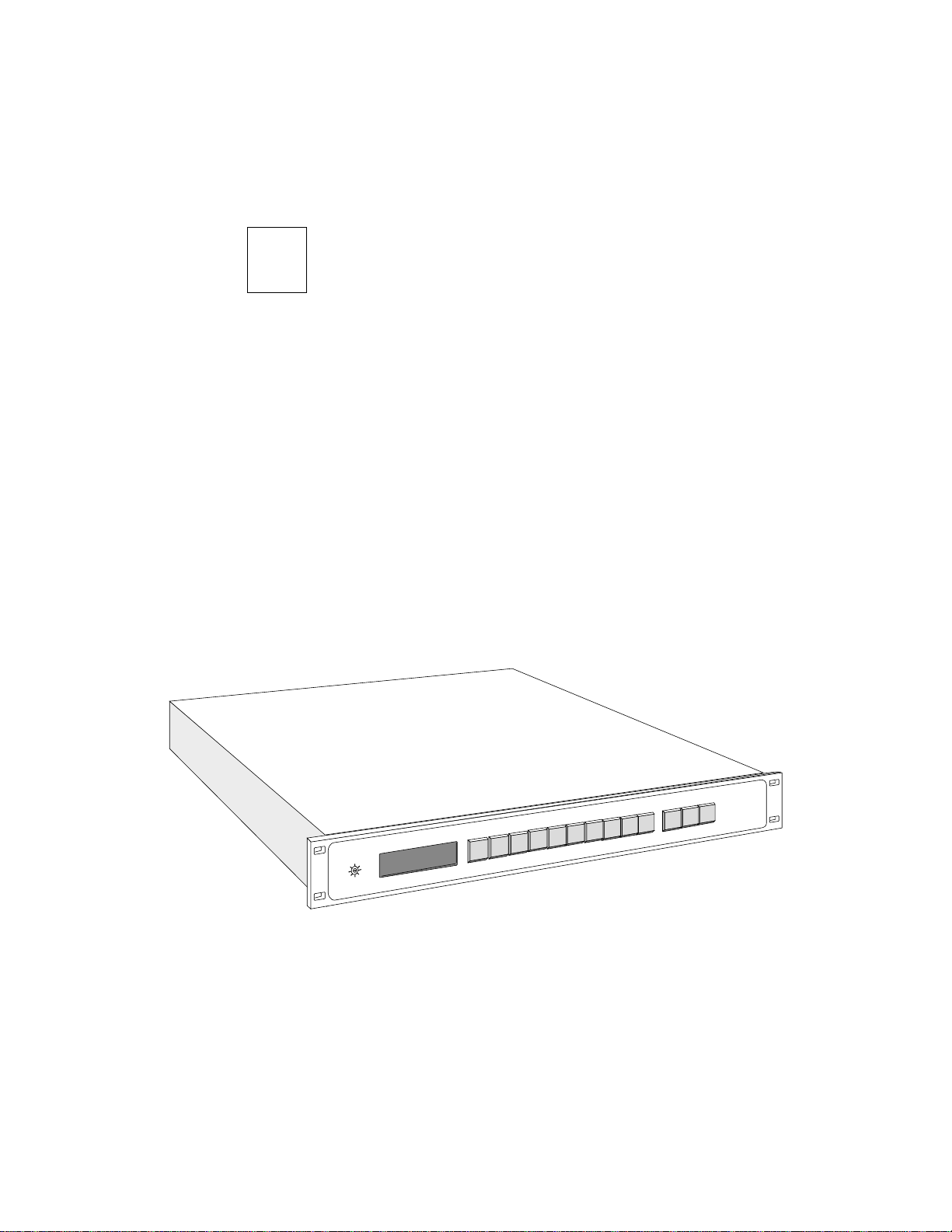
This section provides a general description of the serial digital
version of the Performer™ 10 x 1 Routing Switcher. Included are
Product features
■
Functional description
■
■
Specifications
Performer is a serial digital, 10-input by 1-output, video with dual
(AES/EBU) audio routing system from Grass Valley Group.
8
7
6
5
4
3
2
1
/4
3
h
C
2
A
/2
1
h
C
1
A
V
b
M
0
6
3
O
T
U
A
b
M
0
7
2
T
C
E
IR
D
b
M
7
7
1
b
M
3
4
1
STATUS DISPLAY
INPUT SELECTION
PERFORMER–SD
VAA
GRASS VALLEY GROUP
0
1
9
1-1
Page 22

Section 1 —
Product Description
Performer standard features include:
Automatic television standards compatibility
■
■
AFV or full breakaway operation
■
Protect function
Front panel control
■
■
TEN–XL and TEN–20/20–TEN compatibility
■
Source display for Video, A1, & A2 assignments
RS232, RS422, or RS485 control port
■
ASCII, SMPTE, & production switcher compatibility
■
■
External or internal Vertical Interval strobe select
■
BNC video connectors
■
BNC or D type AES/EBU connectors
■
Dual video and audio outputs
Compact, 1 rack unit construction
■
■
90 to 250-volt operation
■
Relegendable pushbutton caps
Performer options include:
Tally relays for 10 inputs & Joystick Override control
■
■
Remote control panel
Performer circuitry resides in a sealed, 1 rack unit frame. The
standard unit contains just four printed circuit boards. These are:
Rear Motherboard (two versions available)
■
■
VAA board
■
Front Panel board
Power Supply board
■
■
Optional tally relays and GPI inputs can add one more
board, the Tally board, to the system.
1-2
Page 23

Functional Description
System
Functional Description
See descriptions and the block diagram on the following pages.
The PERFORMER Serial Digital Video and AES/EBU Digital
Audio10X1 routing switcher. It is available in four (4) basic
models (configured with either BNC or D type audio connectors
and supplied with either local or remote control panel) as
described below. A bit-rate mode select switch is located on the
front of the local control panel.
D type audio I/O connectors (local or remote control):
Model PFR-SD 10X1 Serial Digital Video & AES/EBU Audio
(female D type connector ), Local Control Version.
Model PFR-SDRC 10X1 Serial Digital Video & AES/EBU Audio
(female D type connector ), Remote Control Version.
BNC type audio I/O connectors (local or remote control):
Model PFR-SDB 10X1 Serial Digital Video & AES/EBU Audio
(75Ω BNC type connector ), Local Control Version.
Model PFR-SDBRC 10X1 Serial Digital Video & AES/EBU Audio
(75Ω BNC type connector ), Remote Control Version.
NOTE:
The two AES/EBU audio channels can be: switched
together with video, switched together separately, or switched
individually. If audio is not synchronous with video, some
disturbances may occur during switching.
Tally and Cable Kit options
The tally option is a module providing contact closures for each
video input. As a video crosspoint is selected, the appropriate
relay closes. This closure can be used to light an external lamp for
tally, or can be used for a bi-directional route for an intercom.
The cable kit option is installed in the frame to permit use of an
additional control panel.
1-3
Page 24

Section 1 —
Product Description
Front panel bit-rate mode switch:
The bit-rate switch on the local control panel allows you to choose
between FORCED, AUTO, or DIRECT modes of matching input/
output bit rates.
• Forced modes include: 143 Mb/s for D2/NTSC; 177 Mb/s for
D2/PAL; 270 Mb/s for D1 both 625 and 525; and 360 Mb/s for
future HDTV use. NOTE: Care must be taken when using the
forced modes of operation; the bit rate selected via the front panel
switch must match the input rate(s).
• AUTO mode: provides automatic bit rate selection when input
rates are different. The PERFORMER automatically detects the
input bit rate and switches to the correct rate, i.e. with D1 at Input
1 and D2 at Input 2 user switches from Input 1 to Input 2. The
switcher will automatically switch to the new rate. NOTE: The
input sources must be locked together and timed).
• DIRECT mode: like the AUTO mode it automatically selects the
input rate and the non-reclocked mode (signal goes directly from
the input to the output without going through the deserializer or
the regenerator circuitry).
1-4
Video
Ten by one (10X1) video switcher. Provides 10 inputs and 1 output
serial digital video switching.
An equalizer is located on each video input path to equalize up to
225m of 8281 cable. The serial data stream output of the equalizers
enter a 10X1 crosspoint.
Audio
Ten by one (10X1) audio switcher. Provides two (2) “stereo” AES/
EBU channels of 10 by 1 serial digital audio switching.
Page 25

Rear Motherboard
All inputs and outputs are through connectors on the Rear
Motherboard. This board has only mechanical functions and
mounts no active circuitry.
There are two different types of rear connector panels available
(unbalanced BNC type audio connectors and balanced D type
audio connctors). Both types accomodate 10 video inputs, 1 pair
of video outputs, 2X10 audio inputs, and 2X2 audio outputs.
Unbalanced BNC type audio connectors
Ten (10) BNC connectors for ten (10) video inputs
Two (2) BNC connectors for the video output pair
Twenty (20) BNC connectors (10 for AES1 and 10 for AES2)
Four (4) BNC connectors (2 for AES1 out and 2 for AES2 out
An IEC connector for the mains power supply
One (1) 25-pin female D type connector for serial communication
and a slot for an optional 25-pin female D type connector
Functional Description
Balanced D type audio connector
Ten (10) BNC connectors for ten (10) video inputs
Two (2) BNC connectors for the video output pair
Two (2) 37-pin D type connectors (one each for AES1 and AES2 in)
An IEC connector for the mains power supply
Twenty-five (25) pin female D type connector for serial
communication and a slot for an optional twenty-five (25) pin
female D type connector
1-5
Page 26

Section 1 — Product Description
VAA Board
The VAA board contains:
■ Video processing circuitry
■ Audio processing circuitry
■ Control circuitry
■ Parameter-determining switches
■ Vertical Interval Strobe generating circuitry
Performer video processing circuitry consists of: ASIC cable
equalizers, an ASIC serial crosspoint, and an ECL line driver.
Serial bit stream at inputs is converted to parallel, and processed
in parallel digital domain, to extract line ID information and to
generate the vertical interval switching strobe.
The Performer supports two independent audio AES/EBU
channels (AUDIO 1/2 and AUDIO 3/4). Inputs can be either
balanced or unbalanced. Audio is received and converted to TTL
signals by RS485 line receiver circuitry. A pair of 8X1 multiplexers
form a 10X1 multiplexer to select one of the ten input signals of
AES Ch 1/2 to the output. AES Ch 3/4 uses identical circuitry.
Control circuitry is based on an 68HC711 CPU running at
4.9152MHz, supported by a 27C256 PROM and a DS1225AD
RAM. The CPU contains a programmable, full-duplex, serial
channel to handle serial data to and from the RS232, RS422, and
RS485 driver and receiver circuits. Three 8-segment switches
allow users to determine serial baud rate, communications
protocol, external or internal VI strobe, and other functions. The
internal VI strobe is stripped from digital video by a TRS ID Data
Separator. An external VI strobe may be used if desired.
1-6
Front Panel Board
The Front Panel board mounts a row of 13 buttons and three, twocharacter, seven-segment displays. The buttons are sequentially
scanned by the VAA board microcomputer (Switch Write); a
pressed button is detected by one of the two Switch Read lines and
the appropriate source taken to the output of the switcher. The
take may be Audio Follow Video or breakaway depending upon
Page 27

the state of the three “breakaway” buttons (V, AES1, and AES2).
The Performer is capable of full breakaway operation, meaning
that video may be separately switched from audio and even the
two audio channels may be separately switched one from the
other.
The microcomputer writes to the displays over an 8-bit parallel
bus. The appropriate display is enabled by a driver output from
the VAA board to accept the source number data.
Power Supply Board
The automatic switchmode Power Supply board delivers +5VDC
to the VAA main board. A step-up converter provides +15VDC
necessary for remote operation and for lighting the front panel
LEDs. Input power may be 100 to 240 volts. The AC line cord is
hardwired to the frame and is UL or TUV selectable at time of
original order.
The AC input is fused but is not user serviceable. This fuse is
soldered onto the power supply circuit board and is accessible to
a qualified service person only by removing the top cover.
Functional Description
Tally Board (option)
The optional Tally board mounts 10 relays and 13 opto-isolated
inputs. The 10 relays are slaved to the video selections made by
the switcher operator. When a video source is selected, the
corresponding relay closes (only a dry contact relay closure is
provided). The opto-isolated inputs provide a connection point
for a Joystick Override or other remote control device.
1-7
Page 28
Section 1 — Product Description
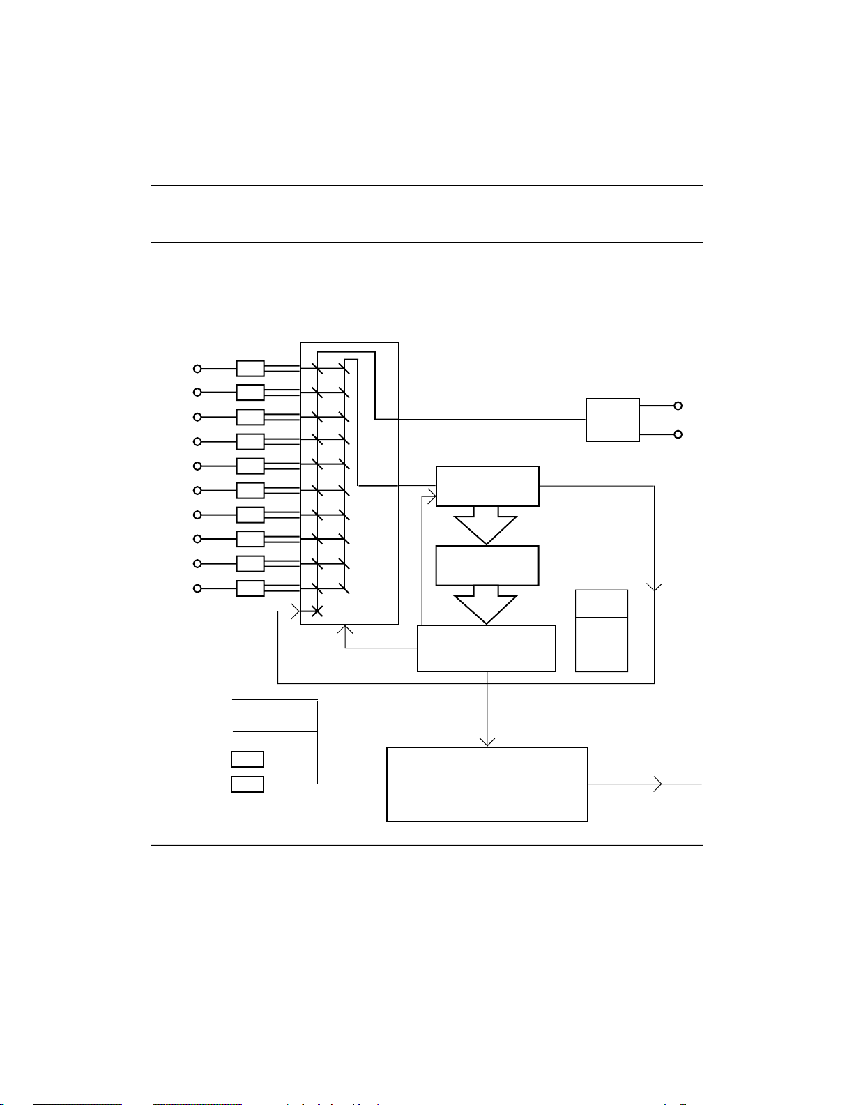
VIDEO/MICROPROCESSOR CONTROLLER
FUNCTIONAL BLOCK DIAGRAM
EQUALIZERS
VIDEO
INPUTS
(1 - 10)
Front Panel
Read/Write
LED Control
GPI/Tally
Options
Serial
Communications
AUTOMATIC
1
2
3
4
5
6
7
8
9
10
11th input
RS422
RS232
16X8 VIDEO
CROSSPOINT
Serial Control
Data Stream
Direct Mode
DESERIALIZER
COPROCESSOR
Indirect Mode
Bit Rate Switch
FIELD PROGRAMMABLE
GATE ARRAY
(Rate Detector)
Vertical
Interval
MICRO-PROCESSOR CONTROLLER
• Front panel control & communication
• RS422/232 communication control
• GPI and Tally control
SERIAL
LINE
DRIVER
(front panel)
Direct
Auto
143Mb/s
177Mb/s
270Mb/s
360Mb/s
To Audio Multiplexer
VIDEO
OUTPUTS
1-8
Page 29
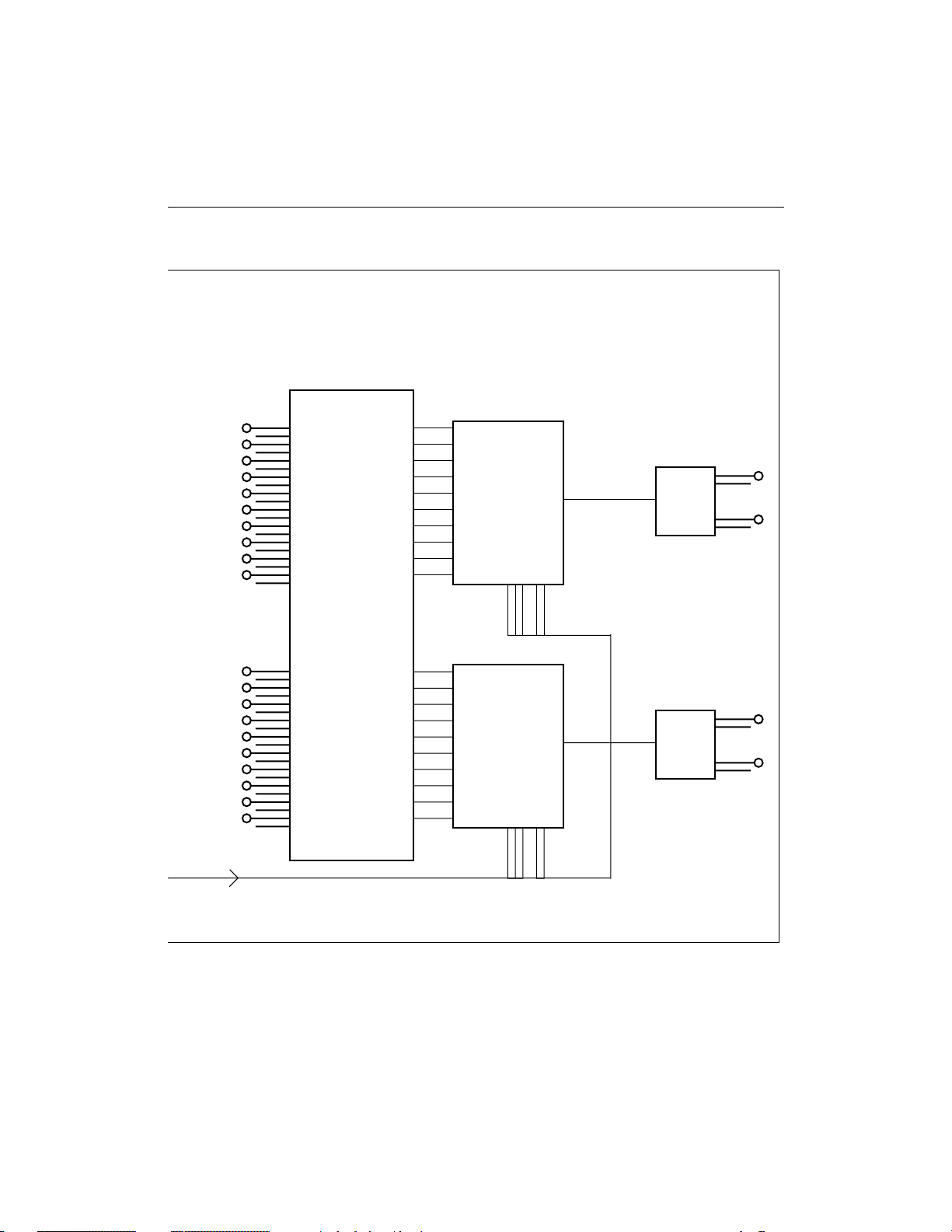
AUDIO
FUNCTIONAL BLOCK DIAGRAM
Functional Description
AES/EBU
AUDIO
INPUTS
(Ch 1)
AES/EBU
AUDIO
INPUTS
(Ch 2)
From Controller
LINE
RECEIVERS
Channel 1
10 X 1
AUDIO
MULTIPLEXER
Channel 2
10 X 1
AUDIO
MULTIPLEXER
RS485
LINE
DRIVER
RS485
LINE
DRIVER
CH 1
OUTPUTS
CH 2
OUTPUTS
1-9
Page 30

Section 1 — Product Description
Performer Specifications
Table 1-1. Performer Specifications
Parameter Performanace
Serial Digital Video Inputs
Video Data Type Serial Digital conforms to SMPTE 259M (D1, D2N, D2P)
Number of inputs Ten (10)
Data Format Selection Internal Selector Switch
Input Impedance 75Ω nominal, self terminating
Input Return Loss >15dB (1MHz to 270MHz)
Connector Type 75Ω BNC (compatible with 50Ω cable ends)
Cable Equalization Automatic for <225m of Belden 8281 up to 270MHz
For direct mode, depends on serial standard and
receiving equipment.
AES/EBU Digital Audio Inputs
Number of Audio Matrices Two (2) 10X1 AES/EBU matrices
Audio Data Type Serial Digital conforms to standard AES3-1992 (ANSI
S4.40-1985)
Number of Inputs Ten per each audio matrix (20 total)
Input Level 400mV <signal level <7Vp-p balanced
Input Connector Type Either balanced female “D” connector or unbalanced
75ΩBNC connector
Input Impedance 110Ω, ±5%, 100KHz to 6MHz (D connector input only)
75Ω, ±5%, 100KHz to 6MHz (BNC connector input only)
Common Mode Voltage +7V, –7V Maximum (D connector input only)
Serial Digital Video Outputs
Video Data Type Serial Digital conforms to SMPTE 259M standard
Number of Outputs Two (2)
Output Impedance 75Ω nominal
Output Return Loss >15dB (1MHz to 360MHz)
Signal Amplitude 800mV ±10% when terminated into 75Ω
D.C. Offset ±0.5V
Rise and Fall Times ≤1.5 nS when terminated into 75Ω
Connector Type 75Ω BNC
1-10
Page 31

Functional Description
Table 1-1. Performer Specifications (continued)
Parameter Performanace
AES/EBU Digital Audio Outputs
Audio Data Type Serial Digital conforms to AES3-1991 (ANSI S4.40-1985)
Number of Outputs Two per audio matrix (4 ea. total)
Output Connector Balanced female “D” or unbalanced 75Ω BNC
Output Level 1.0Vp-p, ±10%, into 75Ω BNC connector.
5Vp-p ±20% into 110Ω balanced Output D connector
(both ±5% and 100KHz to 6MHz)
Operating Modes and Electrical Length
Mode Length
143Mb 38.3 ns
177Mb 37.6 ns
270Mb 36.6 ns
360Mb 35.6 ns
Auto See Above
Direct 26.0 ns (non-reclocked)
Mechanical & Power
Size H-1 Rack Unit, 1.75" (4.45cm); D-10" (25.4cm);
W-EIA standard, 19" (48.3cm)
Weight <15 Lbs (6.75kg)
Temperature Range 0 to 50° C (operational)
Humidity Range 0 to 95% non-condensing (operational)
Operational Range 0-250V AC, 50/60Hz, <45 Watts
Miscellaneous
Vertical Interval
Switching Line 10/525 line standards; Line 6/625 line standards
Control Interfaces RS422 or RS232 25-pin female "D" connector
1-11
Page 32

Section 1 — Product Description
1-12
Page 33

Introduction
2
Installation
Installation Overview
This section provides installation information for Performer
10 x 1 Routing Switcher. Included here are:
■ Installation Overview
■ Common Configurations
■ Installation Reference
This section provides step-by-step installation instructions for the
Performer™ in the following order:
■ Uncrating Unpacking and inspecting the
equipment.
■ Button Labeling Installing supplied source names
under front panel button caps.
■ Rack Mounting Installing frame in an equipment rack.
■ Bit-Rate Selection Selecting correct in/out bit-rates via
front panel bit-rate mode switch.
■ Cabling Making cable connections to frame.
■ Power-Up Applying AC power and running a
brief switcher operating check.
TM
NOTE: Factory default settings allow a single system (frame
including local control panel) and a single remote panel to be
connected and used without following all the procedures
necessary for more complicated installations.
2-1
Page 34

Section 2 — Installation
Uncrating
When you opened the box in which your Performer arrived, you
found this guide. If there was more than one box, they were each
assigned a number. In the box labeled number 1, there was a
System Packing List. Use the packing list to check your order’s
completeness; use the guide to direct you through installation and
operation.
While checking off each item, make sure that no damage was
incurred during shipping. If you find shipping damage, contact
the shipping agency immediately.
Save the shipping containers. You can reuse them any time you
transport the equipment.
Safety Information
WARNING
High voltage. Do not apply AC power with cover removed.
Disconnect AC power before cover is removed.
2-2
Page 35

Button Labeling
Film chips imprinted with standard source names and clear
button caps are included with Performer. Select names which suit
your requirements and install the chips and caps as illustrated.
b
M
0
6
3
A
b
M
0
7
2
b
M
7
7
1
b
M
3
4
1
NOTE: Tally Board and Looping Cable Option .If you order the
Performer and the Tally Board or Looping Cable Option at the same time,
the board is installed at the factory. If you order the Tally Board or
Looping Cable Option later, see the Installation Reference section and
install it as described.
O
T
U
T
C
E
IR
D
A1 CH1/2
V
STATUS DISPLAY
Film Chip
A2 CH1/2
INPUT SELECTION
VTR
27
Installation Overview
Install caps so that the
“fingernail” slots are at top
and bottom.
If the factory settings meet your requirements and you are not installing
a Tally Board or Looping Cable Option, go to Rack-Mounting the
Performer in this section to begin frame installation. If you wish to
make changes in the factory configuration or learn more about potential
settings, go to the Installation Reference section.
2-3
Page 36

Section 2 — Installation
Rack-Mounting the Performer
Performer is designed to mount in a 19-inch equipment rack. The
frame occupies 1 RU (Rack Unit, 1.75 inches/4.45 cm) of vertical
space. The illustration below shows you how to mount the frame
in the rack. The rear rack mounting bracket is supplied with the
frame as shipped. You should consider it if you have a lot of
unsupported cable weight on the back of Performer.
P
U
O
R
G
Y
E
L
L
VA
S
S
A
R
G
D
S
–
R
E
10
9
8
7
6
5
4
3
2
1
2
A
1
A
V
b
M
0
6
3
O
T
U
A
b
M
0
7
2
T
C
E
R
I
D
b
M
7
7
1
b
M
3
4
1
STATUS DISPLAY
INPUT SELECTION
M
R
O
F
R
E
P
VAA
2-4
There are many different rack manufacturers. The size and thread
pitch of mounting screws varies. Thus, these screws must be
supplied by the rack manufacturer or purchased locally.
Page 37

Installation Overview
Front Panel Bit-Rate Mode Switch
The bit-rate switch on the local control panel allows you to choose
between “forced”, AUTO, or DIRECT modes of matching input/
output bit rates. The electrical length of each operating mode is
listed in the specifications section of Section 1 - Product
Description. The modes are described below.
V
b
360M
AUTO
b
270M
177M
b
143M
DIRECT
b
STATUS
• “forced” modes include: 143 Mb/s for D2/NTSC; 177 Mb/s for
D2/PAL; 270 Mb/s for D1 (625 and 525); and 360 Mb/s for future
HDTV use. NOTE: Care must be taken when using any of these
modes of operation, the bit rate selected via the front panel switch
must match the input rate(s).
• AUTO mode: provides automatic bit rate selection when input
rates are different. The PERFORMER automatically detects the
input bit rate and switches to the correct rate (i.e. with D1 at Input
1 and D2 at Input 2 user switches from Input 1 to Input 2. The
switcher will automatically switch to the new rate.) NOTE: The
input sources must be locked together and timed.
• DIRECT mode: like the AUTO mode it automatically selects the
input rate and the non-reclocked mode (signal goes directly from
the input to the output without going through the deserializer or
the regenerator circuitry).
2-5
Page 38

Section 2 — Installation
V
Cabling
Performer cabling is straightforward. Refer to the illustration.
Input 1,
(+) (–) (s)
(s) (+) (–)
Input 2
AC IN
Input 3,
(+) (–) (s)
(s) (+) (–)
Input 4
1
Input 5,
(+) (–) (s)
(s) (+) (–)
9
Input 6
7
Input 7,
(+) (–) (s)
(s) (+) (–)
Input 8
35
Input 9,
(+) (–) (s)
(s) (+) (–)
Input 10
1
Output
(+) (–) (s)
19181716151413121110987654321
373635343332313029282726252423222120
37-Pin, D
Audio Connectors
9
1
7
1
35
AC IN
The Performer power
supply automatically
accepts 120V or 240VAC
input power. No special
settings are necessary.
The frame is shipped with
either TUV or UL AC line
cords as requested in the
original system order.
AUDIO NOTE:
The frame is shipped with
either AES/EBU “D” or
BNC audio connectors.
The BNC frame and the
pinout of the D audio
connectors are shown
above.
8
AUDIO 2 IN
8
AUDIO 1 IN
2
46
A1 OUT
2
46
10
2
A2 OUT
2
10
A1, A2
A1 and A2 audio connectors may be used as left and right channels
for stereo applications, or as two independent audio channels.
AUDIO 1 & 2 (BNC) IN
1. Using 50-ohm coaxial cable,
connect the left or right channel
of your number 1 audio source
to AUDIO 1 IN BNC #1.
2. Connect the remaining
number1 audio source chan-
AUDIO 1 & 2 (BNC) OUT
Two points of connection are
provided for the single output of
each audio channel. Typically,
one is used as a monitor output;
the other as the primary destination.
nels to AUDIO 1 IN BNCs #2 -
10.
3. Connect your second audio
source left or right channel to
AUDIO 2 IN BNC #1.
4. Connect the remaining number
2 audio source channels to AUDIO 2 IN BNCs #2 - 10.
AUDIO 1 & 2 AES/EBU I/O
37-pin D connectors provide left
and right channel inputs and
outputs. Each D connector supports 10 audio inputs and 1 audio output. See above for pinout
information.
2-6
Page 39

tput
–) (s)
Installation Overview
1
7
8
35
AUDIO 1 IN
46
1
V OUT
2
2
Video IN (1-10)
1. Using 75-ohm coaxial cable,
connect your number 1 video
source to Video IN 1 BNC.
2. Connect additional video
sources to V2 through V10
just as you did for V1.
3. Unused inputs must be
terminated with a 75-ohm
load for proper operation.
NOTE
Video sources should be
1V p-p optimum, and must
not exceed 2V p-p. For
AUTO mode, inputs will be
automatically equalized to
270MHz for up to 225m of
BELDEN 8281 cable. For
DIRECT mode, cable length
is dependent on serial
standard and receiving
equipment.
9
7
VIDEO IN
8
10
1
35
2
46
Video Out (V OUT 1 and 2)
Single video output has two
points of connection.
1. Using 75-ohm coaxial cable,
connect the V OUT 1 or
V OUT 2 BNC to the equipment you are feeding.
2. Connect the unused V OUT
BNC in step 1 to additional
equipment or to a video
monitor as necessary.
3.The output cable must be
terminated with a 75-0hm
load for proper operation.
OPTION and REMOTE
Information is located in the
Common Configurations and
Installation Reference subsections of this Installation
section.
OPTION
REMOTE
2-7
Page 40

Section 2 — Installation
Switcher Power-Up
Once you have completed setup, mounting, and cabling you can
apply power to the system and perform an operational check.
To power up and perform an operational check:
At this point, Performer does a self-test.
NOTE: Displays may be accelerated by pressing any of buttons 1
through 8 on the Performer front panel or skipped entirely by
pressing any other button.
Status information is displayed in the following order:
1. Connect the AC line cord from switcher to an AC main.1
Start-up
Display
88 88 88 LED test
rE SE t Warm reset
10 20 TEN-20 compatible
7 68 00 Baud rate
PA r n8 No parity / 8 data bits
SO 1- 10 No source offset
DE St 01 No destination offset
LV L1 23 No level offset
SL AV E0 Master mode
NT SC NTSC video source*
*Performer automatically adjusts itself to NTSC or PAL video
signals.
1. Due to the variation in styles, you must provide and install the
AC plug end for export units (PFR-240).
Protocol or Test
2-8
Page 41

Common Configurations
After setup switch locations are described, this section provides
illustrated switch and cabling information for the most common
configurations.
Common Configurations
■ Performer Remote to Performer
■ PC (Performer ASCII) to Performer
■ PC (TEN-XL ASCII) to Performer
■ PC (Performer ASCII) to Modem to Performer
■ PC (TEN-XL ASCII) to Modem to Performer
■ TEN-XL SCP (XY-mode) to Performer
■ TEN-XL SCP (XY-mode) to Modem to Performer
■ TEN-XL Remote Panels to Performer
■ TNX-AFV19 to Performer
■ 20-TEN XYCP to Performer
■ 100/110 to Performer
■ 200 to Performer
■ 300 to Performer
2-9
Page 42

Section 2 — Installation
Performer Setup Switch Location
While setting up your Performer, you may need to change the
settings of switches S1, S2, and S3 located within the frame. You
won’t have to remove the top cover to access these switches
because a small “slide” cover is located on the frame’s top cover
directly above the switches. See the illustration below.
2-10
S3
OPEN
12345678
12345678
OPEN
OPEN
12345678
S2
1. Remove screw from side of "slide" cover.
S1
2. Hold "slide" cover tightly against side of
frame and remove top screw.
3. Slide cover to the left to open.
Page 43

Performer Remote to Performer
Common Configurations
Performer Remote Control Panel
12345678910
VA1A2
Dot indicates
switch down
on that side
12345678ON12345678
AUDIO
VIDEO
Grass Valley Group
AUDIO
PERFORMER–SD
1
2
REMOTE
1234
These are default settings; unless you
have changed the settings, proceed to
cabling.
12345678
12345678
OPEN
1
1234
OPEN
Performer
12345678910
V A1 CH1/2 A2 CH3/4
360Mb
270Mb
AUTO
177Mb
DIRECT
143Mb
S3
OPEN
12345678
OPEN
S2
OPEN
Grass Valley Group
A1
A2
VIDEO
PERFORMER–SD
CH1/2
CH3/4
VAA
S1
12345678
Dot indicates
switch down
on that side
12345678
These are default settings; unless you
have changed the settings, proceed to
cabling.
35
7
AUDIO 2 IN
8
46
Performer–SD
AES/EBU IN/OUT 1AES/EBU IN/OUT 2
Performer–SDB
1
9
1
7
AUDIO 1 IN
A1 OUT V OUT
2
8
10
2
AC IN
9
1
AC IN
A2 OUT
10
2
9
1
V OUT
2
1
1
35
2
2
46
1
35
7
VIDEO IN
8
10
2
46
9
1
35
7
VIDEO IN
8
10
2
46
14
1
OPTION
REMOTE
OPTION
REMOTE
25
13
Performer
9 pin
Female
RS485 (+) 3
RS485 (-) 8
GND (S) 9
Cable (max 2000'/610m)
User fabricated
Performer
25 pin
Male
1 RS485 (+)
2 RS485 (-)
18 GND (S)
2-11
Page 44

Section 2 — Installation
PC (Performer ASCII) to Performer
PC (Performer ASCII)
Baud 9600
Data Bit 7
Parity Odd
Stop 1
25
Performer
12345678910
V A1 CH1/2 A2 CH3/4
360Mb
270Mb
AUTO
177Mb
DIRECT
143Mb
S3
OPEN
12345678
OPEN
S2
OPEN
12345678
35
7
AUDIO 2 IN
8
46
Performer–SD
AES/EBU IN/OUT 1AES/EBU IN/OUT 2
Performer–SDB
1
9
1
A1 OUT V OUT
2
2
35
7
AUDIO 1 IN
8
10
46
1
2
AC IN
9
1
AC IN
A2 OUT
10
2
1
S1
V OUT
1
2
1
2
VIDEO
12345678
9
10
9
10
Grass Valley Group
A1
A2
CH1/2
CH3/4
Dot indicates
switch down
on that side
7
VIDEO IN
8
7
VIDEO IN
8
14
1
PERFORMER–SD
VAA
1
35
2
46
1
35
2
46
OPTION
REMOTE
OPTION
REMOTE
25
13
2-12
PC
25 pin
Female
TXD 2
RXD 3
GND 7
Cable (max 50'/15.25m)
TNX-IRS (056857)
Performer
25 pin
Male
16 RXD
3 TXD
18 GND
Page 45

Common Configurations
PC (Performer ASCII) to Performer (cont.)
The following is an example of a Performer ASCII string used to
control a Performer via a PC. The command string will switch
video input number 5 on all levels of the Performer (video, audio
1, and audio 2).
Performer ASCII command strings:
■ Preset string – ^M0007D000501
■ Take string – ^M0003T01
Table 2-1.
ASCI
I
Description
Preset String
Byte 1 ^M carriage return
Byte 2 00 Performer address
Byte 3 07 number of data string characters
CMD D data preset, source to destination
Byte 4 00 level, 00 = all levels
Byte 5 05 input selection
Byte 6 01 output selection
Take Strings
Byte 1 ^M carriage return
Byte 2 00 Performer address
Byte 3 03 number of data string characters
CMD T take the specified destination
Byte 4 01 output selection
2-13
Page 46

Section 2 — Installation
PC (Performer ASCII) to Modem to Performer
PC (Performer ASCII)
Baud 1200
Data Bit 7
Parity Odd
Stop 1
1
25
Modem*
V A1 CH1/2 A2 CH3/4
360Mb
270Mb
AUTO
177Mb
DIRECT
143Mb
Performer
12345678910
S3
OPEN
S2
OPEN
S1
12345678
OPEN
VIDEO
12345678
CH1/2
Grass Valley Group
A1
A2
PERFORMER–SD
CH3/4
Dot indicates
switch down
on that side
VAA
12345678
7
AUDIO 2 IN
8
Performer–SD
AES/EBU IN/OUT 1AES/EBU IN/OUT 2
Performer–SDB
1
9
35
1
7
A1 OUT V OUT
2
8
10
46
2
AUDIO 1 IN
AC IN
9
1
AC IN
A2 OUT
10
2
1
25
25
1
9
1
V OUT
2
1
1
35
2
2
46
1
OPTION
35
7
VIDEO IN
8
10
9
7
8
10
REMOTE
2
46
1
35
OPTION
VIDEO IN
2
46
REMOTE
14
1
25
13
SCP
25 pin
Female
TXD 2
RXD 3
GND 7
Cable (max 50'/15.25m)
TNX-CTM (056862)
Modem
25 pin
Male
2 RXC
3 TXD
7 GND
Modem
25 pin
Male
TXD 2
RXD 3
GND 7
Cable (max 50'/15.25m)
TNX-MIC (056861)
Performer
25 pin
Male
16 RXD
3 TXD
18 GND
*Disable or turn off modem response codes to terminal, or select the mode which sends them
as numbers; disable or turn off command character echo.
2-14
Page 47

Common Configurations
PC (Performer ASCII) to Modem to Performer (cont.)
The following is an example of a Performer ASCII string used to
control a Performer via a PC. The command string will switch
video input number 5 on all levels of the Performer (video, audio
1, and audio 2).
Performer ASCII command strings:
■ Preset string – ^M0007D000501
■ Take string – ^M0003T01
Table 1-2.
ASCI
I
Description
Preset String
^M carriage return
00 Performer address
07 number of data string characters
D CMD = data preset, source to destination
00 level, 00 = all levels
05 input selection
01 output selection
Take String
^M carriage return
00 Performer address
03 number of data string characters
T CMD = take the specified destination
01 output selection
2-15
Page 48

Section 2 — Installation
PC (TEN-XL ASCII) to Performer
PC (TEN-XL ASCII)
Baud 9600
Data Bit 7
Parity Odd
Stop 1
25
Performer
12345678910
V A1 CH1/2 A2 CH3/4
360Mb
270Mb
AUTO
177Mb
DIRECT
143Mb
S3
OPEN
12345678
OPEN
S2
OPEN
12345678
35
7
AUDIO 2 IN
8
46
Performer–SD
AES/EBU IN/OUT 1AES/EBU IN/OUT 2
Performer–SDB
1
9
1
A1 OUT V OUT
2
2
35
7
AUDIO 1 IN
8
10
46
AC IN
9
1
AC IN
A2 OUT
10
2
1
Grass Valley Group
A1
A2
VIDEO
PERFORMER–SD
CH1/2
CH3/4
VAA
S1
12345678
Dot indicates
switch down
on that side
9
1
V OUT
10
2
9
1
1
10
2
2
1
OPTION
35
7
VIDEO IN
8
7
8
REMOTE
2
46
1
35
OPTION
VIDEO IN
2
46
REMOTE
14
1
25
13
2-16
PC
25 pin
Female
TXD 2
RXD 3
GND 7
Cable (max 50'/15.25m)
TNX-IRS (056857)
Performer
25 pin
Male
16 RXD
3 TXD
18 GND
Page 49

PC (TEN-XL ASCII) to Performer (cont.)
The following is an example of a TEN-XL ASCII string used to
control a Performer via a PC. The command string will switch
video input number 4 and both audio channels to input number 6.
TEN-XL ASCII protocol does not allow left and right audio
channel breakaway.
TEN-XL ASCII command string: ^B0035
Table 2-2.
ASCII Description
Byte 1 ^B start of transmission
Byte 2 00 Performer address
Byte 3 35 video crosspoint 4*
audio crosspoint 6*
Common Configurations
*The video and audio crosspoints are numbered 0 through 9.
2-17
Page 50

Section 2 — Installation
PC (TEN-XL ASCII) to Modem to Performer
PC (Performer ASCII)
Baud 1200
Data Bit 7
Parity Odd
Stop 1
1
25
Modem*
V A1 CH1/2 A2 CH3/4
360Mb
270Mb
AUTO
177Mb
DIRECT
143Mb
Performer
12345678910
S3
OPEN
S2
OPEN
S1
12345678
OPEN
VIDEO
CH1/2
12345678
Grass Valley Group
A1
A2
PERFORMER–SD
CH3/4
Dot indicates
switch down
on that side
VAA
12345678
35
7
AUDIO 2 IN
8
46
Performer–SD
AES/EBU IN/OUT 1AES/EBU IN/OUT 2
Performer–SDB
1
9
1
7
AUDIO 1 IN
A1 OUT V OUT
2
8
10
2
AC IN
9
1
AC IN
A2 OUT
10
2
1
25
25
1
9
1
V OUT
10
2
1
1
35
2
2
46
1
OPTION
35
7
VIDEO IN
8
9
7
8
10
REMOTE
2
46
1
35
OPTION
VIDEO IN
2
46
REMOTE
14
1
25
13
SCP
25 pin
Female
TXD 2
RXD 3
GND 7
Cable (max 50'/15.25m)
TNX-CTM (056862)
Modem
25 pin
Male
2 RXC
3 TXD
7 GND
Modem
25 pin
Male
TXD 2
RXD 3
GND 7
Cable (max 50'/15.25m)
TNX-MIC (056861)
Performer
25 pin
Male
16 RXD
3 TXD
18 GND
*Disable or turn off modem response codes to terminal, or select the mode which sends them
as numbers; disable or turn off command character echo.
2-18
Page 51

PC (TEN-XL ASCII) to Modem to Performer (cont.)
The following is an example of a TEN-XL ASCII string used to
control a Performer via a PC. The command string will switch
video input number 4 and both audio channels to input number 6.
TEN-XL ASCII protocol does not allow left and right audio
channel breakaway.
TEN-XL ASCII command string: ^B0035
ASCII Description
^B start of transmission
00 Performer address
35 video crosspoint 4*
Common Configurations
Table 2-3.
audio crosspoint 6*
*The video and audio crosspoints are numbered 0 through 9.
2-19
Page 52

Section 2 — Installation
TEN X L
TEN-XL SCP (XY-mode) to Performer
TEN-XL SCP
12345678910 12345678910
Grass Valley Group
OPEN
12345678
S1
SERIAL CONTROL PANEL
Performer
12345678910
V A1 CH1/2 A2 CH3/4
360Mb
270Mb
AUTO
177Mb
DIRECT
143Mb
S3
OPEN
12345678
OPEN
OPEN
12345678
S2
35
7
AUDIO 2 IN
8
46
Performer–SD
AES/EBU IN/OUT 1AES/EBU IN/OUT 2
Performer–SDB
1
9
1
A1 OUT V OUT
2
2
35
7
AUDIO 1 IN
8
10
46
1
2
AC IN
9
1
AC IN
A2 OUT
10
2
1
25
Grass Valley Group
A1
A2
VIDEO
PERFORMER–SD
CH1/2
CH3/4
VAA
12345678
S1
Dot indicates
switch down
on that side
9
1
V OUT
10
2
9
1
10
2
1
OPTION
35
7
VIDEO IN
8
7
8
1
REMOTE
2
46
1
35
OPTION
VIDEO IN
2
46
REMOTE
14
25
13
TEN-XL
25 pin
Female
TXD 2
RXD 3
GND 7
Cable (max 50'/15.25m)
Performer
25 pin
Male
16 RXD
3 TXD
18 GND
TNX-IRS (056857)
To control more than one Performer, see additional information in Installation Reference section.
2-20
Page 53

Common Configurations
TEN X L
TEN-XL SCP (XY-mode) to Modem to Performer
TEN-XL SCP
12345678910 1 2345678910
Grass Valley Group
OPEN
12345678
S1
25
SERIAL CONTROL PANEL
1
Modem*
A1 CH1/2 A2 CH3/4
V
360Mb
270Mb
AUTO
177Mb
DIRECT
143Mb
Performer
12345678910
S3
OPEN
12345678
OPEN
OPEN
VIDEO
12345678
A1
CH1/2
Grass Valley Group
A2
PERFORMER–SD
CH3/4
S1
Dot indicates
switch down
on that side
VAA
12345678
S2
35
7
AUDIO 2 IN
8
46
Performer–SD
AES/EBU IN/OUT 1AES/EBU IN/OUT 2
Performer–SDB
1
9
1
7
AUDIO 1 IN
A1 OUT
2
8
10
2
AC IN
9
1
AC IN
A2 OUT
10
2
1
25
25
1
9
1
7
V OUT
8
10
2
9
1
1
35
46
7
V OUT
8
10
2
2
OPTION
1
35
VIDEO IN
REMOTE
2
46
OPTION
1
35
VIDEO IN
REMOTE
2
46
13
25
1
14
TEN-XL
25 pin
Female
TXD 2
RXD 3
GND 7
Cable (max 50'/15.25m)
TNX-CTM (056862)
Modem
25 pin
Male
RXC 2
TXD 3
GND 7
Modem
25 pin
Male
TXD 2
RXD 3
GND 7
Cable (max 50'/15.25m)
TNX-MIC (056861)
Performer
25 pin
Male
16 RXD
3 TXD
18 GND
*Disable or turn off modem response codes to terminal, or select the mode which sends them as
numbers; disable or turn off command character echo.
To control more than one Performer, see additional information in Installation Reference section.
2-21
Page 54

Section 2 — Installation
TEN X L
TEN-XL Remote Panels to Performer
TEN-XL Remote Panels
Grass Valley Group
TEN-XL Remote panels include:
TNX-RCP, TNX-AFV, TNX-TCP,
TNX-SMP, TNX-2AFV
25
Performer
12345678910
V
A1 CH1/2 A2 CH3/4
360Mb
270Mb
AUTO
177Mb
DIRECT
143Mb
S3
OPEN
12345678
OPEN
OPEN
12345678
S2
35
7
AUDIO 2 IN
8
46
Performer–SD
AES/EBU IN/OUT 1AES/EBU IN/OUT 2
Performer–SDB
1
9
1
35
7
AUDIO 1 IN
A1 OUT
2
8
10
2
46
AC IN
9
1
AC IN
A2 OUT
10
2
1
Grass Valley Group
A1
A2
VIDEO
PERFORMER–SD
CH1/2
CH3/4
VAA
12345678
S1
Dot indicates
switch down
on that side
9
1
7
V OUT
8
10
2
9
1
1
7
V OUT
8
10
2
2
OPTION
1
35
VIDEO IN
REMOTE
2
46
OPTION
1
35
VIDEO IN
REMOTE
2
46
1
25
TNX
25 pin
Male
1
25
Cable (max 1000'/305m)
Performer
25 pin
Male
1
25
TNX-RCC (056851)
Pins are one to one
To control more than one Performer, see additional information in Installation Reference section.
2-22
Page 55

TNX-AFV19 to Performer
TEN X L
Common Configurations
TEN-AFV19
Grass Valley Group
Performer (Primary and Secondary)
Note: Switch settings for S2 are different
for primary and secondary, see below.
12345678910
V
A1 CH1/2 A2 CH3/4
360Mb
270Mb
AUTO
177Mb
DIRECT
143Mb
S3
OPEN
12345678
OPEN
VIDEO
12345678
OPEN
Grass Valley Group
A1
A2
PERFORMER–SD
CH1/2
CH3/4
S1
Dot indicates
switch down
on that side
VAA
12345678
S2
Primary Performer
(increments 1 to 10)
Secondary Performer
(increments 2 to 10)
S3
OPEN
12345678
OPEN
OPEN
12345678
S1
Dot indicates
switch down
on that side
12345678
S2
35
7
AUDIO 2 IN
8
46
Performer–SD
AES/EBU IN/OUT 1AES/EBU IN/OUT 2
Performer–SDB
1
9
1
7
AUDIO 1 IN
A1 OUT
2
8
10
2
J1S
1
25
J1P
1
25
AC IN
9
1
AC IN
A2 OUT
10
2
9
1
7
V OUT
8
10
2
9
1
1
35
7
V OUT
8
10
2
2
46
OPTION
1
35
VIDEO IN
REMOTE
2
46
OPTION
1
35
VIDEO IN
REMOTE
2
46
13
1
TNX
25 pin
Male
TNX
25 pin
Male
1
25
Cable (max 1000'/305m)
TNX-RCC (056851)
Pins are one to one
Requires two cables
(Primary & Secondary)
Performer 25 pin
Male
1
Note: Wiring is identical
for both primary and
secondary Performers.
25
25
14
2-23
Page 56

Section 2 — Installation
20-TEN XYCP to Performer
TEN-20 XYCP
LEVEL 1 LEVEL 2 LEVEL 3 LEVEL 4 DESTINATION
1
2
3
OPEN
LEVELS
4
5
6
7
8
OPEN
PANEL
NUMBER
12345678
12345678
12345678
OPEN
OPEN
OPEN
Performer
0123 4
PROTECT
CLEAR
LAST
TAKE
5678 9
Grass Valley Group
1
2
3
4
5
6
7
8
OPEN
1
2
3
4
5
6
7
8
360Mb
270Mb
AUTO
177Mb
DIRECT
143Mb
DEST
AC IN
AC IN
A2 OUT
12345678910
V
A1 CH1/2 A2 CH3/4
S3
S2
9
1
35
7
AUDIO 2 IN
8
10
2
46
OPEN
12345678
OPEN
12345678
Performer–SD
AES/EBU IN/OUT 1AES/EBU IN/OUT 2
Performer–SDB
1
9
1
35
7
AUDIO 1 IN
A1 OUT
2
8
10
2
46
OPEN
1
2
Grass Valley Group
A1
A2
VIDEO
PERFORMER–SD
CH1/2
CH3/4
VAA
12345678
S1
Dot indicates
switch down
on that side
9
1
7
V OUT
8
10
2
9
1
7
V OUT
8
10
2
OPTION
1
35
VIDEO IN
REMOTE
2
46
OPTION
1
35
VIDEO IN
REMOTE
2
46
13
25
1
14
TEN-20 XYCP
3 pin
Female
RS485 (+)
150-ohm resistor
RS485 (-)
GND (S)
Cable (max 2000'/610m)
Performer
25 pin
Male
1 RS485 (+)
2 RS485 (-)
18 GND
Three strand coax
(Belden 8451)
To control more than one Performer, see additional information in Installation Reference section.
2-24
Page 57

Common Configurations
Model 100/110 to Performer (Always Follow mode)
Model 100/110
Baud 38400
Data bit 8
Parity odd
Address 30
Serial Interface Board
1 2 3 4 5 6 7 8 1 2 3 4 5 6 7 8
S1 o o c c o o o o S2 o o o o o o o c
Control Processor Board
Set jumpers J5, J6 & J7 to RS-422
Set baud rate jumper J9 to pos. E
100/110 Control Panel
Editor Enable ON
1
Performer (Always Follow mode)
12345678910
V A1 CH1/2 A2 CH3/4
360Mb
270Mb
AUTO
177Mb
DIRECT
143Mb
S3
OPEN
12345678
OPEN
OPEN
12345678
S2
35
AUDIO 2 IN
46
Performer–SD
AES/EBU IN/OUT 1AES/EBU IN/OUT 2
Performer–SDB
1
9
1
A1 OUT V OUT
2
2
35
7
AUDIO 1 IN
8
10
46
1
2
AC IN
9
1
7
AC IN
A2 OUT
8
10
2
Grass Valley Group
A1
A2
VIDEO
PERFORMER–SD
CH1/2
CH3/4
VAA
S1
12345678
Dot indicates
switch down
on that side
9
1
V OUT
10
2
9
1
10
2
1
1
OPTION
35
7
VIDEO IN
8
7
VIDEO IN
8
REMOTE
2
46
1
35
OPTION
2
46
REMOTE
14
25
13
100/110
9 pin
Male
GND 9
TX- 2
RX+ 3
TX+ 7
RX- 8
Cable (max 4000'/1220m)
TNX-ICC (056855)
Performer
25 pin
Male
18 GND
15 RX1 TX+
14 RX+
2 TX-
2-25
Page 58

Section 2 — Installation
Model 100/110 to Performer (Conditional mode)
Model 100/110
Baud 38400
Data bit 8
Parity odd
Address 30
Serial Interface Board
1 2 3 4 5 6 7 8 1 2 3 4 5 6 7 8
S1 o o c c o o o o S2 o o o o o o o c
Control Processor Board
Set jumpers J5, J6 & J7 to RS-422
Set baud rate jumper J9 to pos. E
100/110 Control Panel
Editor Enable ON
1
Performer (Conditional mode)
12345678910
V A1 CH1/2 A2 CH3/4
360Mb
270Mb
AUTO
177Mb
DIRECT
143Mb
S3
OPEN
12345678
OPEN
12345678
S2
35
AUDIO 2 IN
46
Performer–SD
AES/EBU IN/OUT 1AES/EBU IN/OUT 2
Performer–SDB
1
9
1
7
AUDIO 1 IN
A1 OUT V OUT
2
8
10
2
AC IN
9
1
7
AC IN
A2 OUT
8
10
2
35
46
OPEN
1
2
Grass Valley Group
A1
A2
VIDEO
PERFORMER–SD
CH1/2
CH3/4
VAA
S1
12345678
Dot indicates
switch down
on that side
9
1
V OUT
10
2
9
1
10
2
1
1
OPTION
35
7
VIDEO IN
8
7
VIDEO IN
8
REMOTE
2
46
1
35
OPTION
2
46
REMOTE
14
25
13
2-26
100/110
9 pin
Male
GND 9
TX- 2
RX+ 3
TX+ 7
RX- 8
Cable (max 4000'/1220m)
TNX-ICC (056855)
Performer
25 pin
Male
18 GND
15 RX1 TX+
14 RX+
2 TX-
Page 59

Model 200 to Performer
Common Configurations
Model 200
Baud 38400
Data bit 8
Parity odd
Address 1
200 Panel
Streamlline Menu
Select Misc. Menu
Select Periph
Select Peri 1
1
Grass Valley Group
Performer
12345678910
V A1 CH1/2 A2 CH3/4
360Mb
270Mb
AUTO
177Mb
DIRECT
143Mb
S3
OPEN
12345678
OPEN
OPEN
12345678
S2
35
7
AUDIO 2 IN
8
46
Performer–SD
AES/EBU IN/OUT 1AES/EBU IN/OUT 2
Performer–SDB
1
9
1
A1 OUT V OUT
2
2
35
7
AUDIO 1 IN
8
10
46
1
2
AC IN
9
1
AC IN
A2 OUT
10
2
Grass Valley Group
A1
A2
VIDEO
PERFORMER–SD
CH1/2
CH3/4
VAA
S1
12345678
Dot indicates
switch down
on that side
9
1
V OUT
10
2
9
1
10
2
1
1
OPTION
35
7
VIDEO IN
8
7
8
REMOTE
2
46
1
35
OPTION
VIDEO IN
2
46
REMOTE
14
25
13
200 Port 1
9 pin
Female
GND 9
TX- 2
RX+ 3
TX+ 7
RX- 8
Cable (max 4000'/1220m)
TNX-ICC (056855)
Performer
25 pin
Male
18 GND
15 RX1 TX+
14 RX+
2 TX-
2-27
Page 60

Section 2 — Installation
Model 300 to Performer
Model 300
Baud 38400
Data bit 8
Parity odd
Address 1
300 Panel
Streamlline Menu
Select Misc. Menu
Select Periph
Select Peri 1
1
Grass Valley Group
Performer
12345678910
V A1 CH1/2 A2 CH3/4
360Mb
270Mb
AUTO
177Mb
DIRECT
143Mb
S3
OPEN
12345678
OPEN
OPEN
12345678
S2
35
AUDIO 2 IN
46
Performer–SD
AES/EBU IN/OUT 1AES/EBU IN/OUT 2
Performer–SDB
1
9
1
A1 OUT V OUT
2
2
35
7
AUDIO 1 IN
8
10
46
1
2
AC IN
9
1
7
AC IN
A2 OUT
8
10
2
Grass Valley Group
A1
A2
VIDEO
PERFORMER–SD
CH1/2
CH3/4
VAA
S1
12345678
Dot indicates
switch down
on that side
9
1
V OUT
10
2
9
1
10
2
1
1
OPTION
35
7
VIDEO IN
8
7
8
REMOTE
2
46
1
35
OPTION
VIDEO IN
2
46
REMOTE
14
25
13
2-28
200 Port 1
9 pin
Female
GND 9
TX- 2
RX+ 3
TX+ 7
RX- 8
Cable (max 4000'/1220m)
TNX-ICC (056855)
Performer
25 pin
Male
18 GND
15 RX1 TX+
14 RX+
2 TX-
Page 61

Installation Reference
Installation Reference
The Installation Reference section may be viewed as two distinct
installation sub-sections:
Frame top cover removal/replacing
■ Removing/replacing frame top cover
■ Removing/replacing terminating resistors
■ Remote connector cabling
■ Option connector cabling
■ Tally board option installation
■ Looping cable option installation
Access to internal switches via frame top “slide-cover”
■ Vertical interval strobe selection
■ Switch reference
■ Switcher polling address
■ Serial communications protocol selection
2-29
Page 62

Section 2 — Installation
Frame Top Removal and Replacement
The Performer frame is EMI (electromagnetic interference) tight.
To gain access to change factory settings and set operating
voltage, it is necessary to remove the frame top cover. The
illustration below shows you how.
WARNING
Lethal voltages present inside frame. DO NOT apply AC
power with cover removed! Disconnect AC power before
removing cover.
Removal
1. Disconnect AC power.
2. Remove the six large phillips machine screws from each
side of the frame and the ten smaller screws from the top.
2-30
/4
3
H
C
2
A
/2
1
H
C
1
A
V
360Mb
AUTO
270Mb
DIRECT
177Mb
143Mb
Y
LA
P
IS
D
S
ATU
T
S
INPUT SELECTION
3. Lift the top back and up and set it aside.
GRASS VALLEY GROUP
GRASS VALLEY GROUP
PERFORM
A
A
V
–SD
ER
Page 63

/2
1
H
C
1
A
V
360Mb
AUTO
270Mb
DIRECT
177Mb
143Mb
STATU
D
S
Replacement
C
2
A
LA
P
IS
Front Lip
/4
3
H
Y
INPUT SELECTION
Installation Reference
GRASS VALLEY GROUP
GRASS VALLEY GROUP
PERFORMER
A
A
V
–SD
CAUTION
Wait until all configuration changes are complete. Then replace
the top in reverse order from its removal. Performer setups are
discussed on the following pages.
When replacing the top, make sure you slide the lip into the front
panel slot.
If the top is not replaced exactly according to instructions, it will
no longer be EMI tight.
2-31
Page 64

Section 2 — Installation
Removing/Replacing Terminating Resistors
When using your unit with more than one other device, you must
decide where your unit is to reside on the control bus. Depending
on its location on the bus, you may need to remove resistor R400.
NOTE: The silkscreen text on board may be incorrect.
■ If your unit will reside at the end of the bus, leave R400 in
place
■ If your unit will reside mid-bus, remove R400
■ R401 should not be installed in either case
R401
Remove
R400
Remove if not
at end of bus
NOTE: If Tally Relay Board
or Looping option is installed,
ribbon cables may have to be
moved to see resistors.
S3
OPEN
12345678
OPEN
12345678
S2
26-pin ribbon cable
12345678
OPEN
S1
Bit-Rate
Mode
Select
Switch
(052781)
optional
Tally Board
(066921-10)
40-pin ribbon cable
(054661-00)
40-pin ribbon cable
(054661-01)
AES/EBU IN/OUT 1
Connector
AES/EBU IN/OUT 2
Connector
Power Supply
(PE1298-00)
AC Line Cord
Receptacle
2-32
Page 65

CAUTION
Installation Reference
Remote Connector Cabling
The 25-pin, female D REMOTE connector provides a point of
connection for:
■ Optional remote control panel (RS485)
■ RS232, RS422 interface
■ External Vertical Interval Strobe
Connector pin numbering is illustrated below. Table 2-4 lists the
signal-to-pin number correlation.
If you are adding your own control device, using RS422 or RS485
control, you may need to construct a connecting cable.
Both RS422 and RS485 control require terminating resistors as
described in Removing/Replacing Terminating Resistors
later in this section. When cabling, be sure the terminating
resistor is installed at the end of the RS422 or RS485 bus.
14 25
113
REMOTE
Table 2-4. REMOTE Connector Pin Assignments
Signal Pin
VA (bit A of 4-bit binary video status 13
VB (bit B of 4-bit binary video status 25
VC (bit C of 4-bit binary video status) 24
25 24 2322 21 20 19 18 17 16 15 14
13121110987654321
2-33
Page 66

Section 2 — Installation
Table 2-4. REMOTE Connector Pin Assignments - (continued)
Signal Pin
VD (bit D of 4-bit binary video status) 23
AA (bit A of 4-bit binary audio status) 5
AB (bit B of 4-bit binary audio status) 6
AC (bit C of 4-bit binary audio status) 7
AD (bit D of 4-bit binary audio status) 8
O (bit O of 5-bit binary source select) 19
A (bit A of 5-bit binary source select) 21
B (bit B of 5-bit binary source select) 22
C (bit C of 5-bit binary source select) 9
D (bit D of 5-bit binary source select) 20
KEY ON (active low - any button press) 12
A ONLY (active low - audio only select) 10
V ONLY (active low - video only select) 11
TX RS422+ (RS485 <+>) 1
TX RS422– (RS485 <->) 2
RX RS422+ 14
RX RS422– 15
TX RS232 3
RX RS232 16
VI Strobe 4
Ground (RS485 <S>) 18
≈ +20V DC 17
2-34
Page 67

OPTION Connector Cabling
The OPTION connector slot may be used in two ways:
■ With Tally Board option, which allows Joystick Override/
Custom Control and Tally Relay connection
■ With Looping option, which parallels and duplicates the
pinouts of the REMOTE connector.
Tally Board Option
When used to connect Joystick Override or a custom control
panel, an optional Tally Relay Board and cable/connector
assembly must be installed in Performer. This installation is
described next in this section. Once the Tally Relay Board and
connector are installed, you can cable control and tally as
illustrated below and listed in Table 2-5. (See the
section of this guide for Joystick Override and control operating
information.)
Relay closures follow video source selections. When the
corresponding video source is selected, the relay closes and
remains closed until the video source is released.
Installation Reference
Operation
CAUTION
14 25
113
OPTION
25 24 2322 21 20 19 18 17 16 15 14
13121110987654321
Relays provide DRY CONTACT CLOSURE only. NO
VOLTAGE or PATH TO GROUND is provided. Relays are
rated at 42.4 volts, (30- volts RMS), 1 Amp,ere resistive or
inductive. UL Safety Extra Low Voltage requirements must be
met
2-35
Page 68

Section 2 — Installation
12345678
Tally Board Option Installation
The Tally Board option allows you to use a custom control panel
or Joystick Override to control the Performer, and provides tally
relay closures which follow the video switching level. (See the
Operation section for Tally Board function.)
Refer to the illustrations on the following pages to remove the top
cover and install the Tally Board. The Tally Board mounts on
standoffs on the Digital VAA (Video, Audio, Audio) Board. Follow
steps below to install Tally Board.
1. Using the hardware provided, install the Tally Board as
shown and described in the illustration below.
2. Attach the 26-pin ribbon cable (052781) between Tally
Board connector P2 and VAA Board connector P4.
3. Attach the 40-pin ribbon cable (054661) between Tally
Board connector P1 and VAA Board connector P3.
40-pin ribbon cable
(054661-00)
2-36
26-pin ribbon cable
(052781)
optional
Tally Board
(066921-10)
123
OPEN
S3
WARNING
High voltages
inside frame! Do not
apply AC power
with cover removed.
Side View, Standoffs.
1. Position Tally Board as shown.
2. Press extruded “feet” on
standoffs into holes on VAA
Board.
Page 69

Installation Reference
29
Once the Tally Board option has been installed, the OPTION
connector is linked to the Tally Board via a ribbon cable; the Tally
Board, in turn, is linked to the VAA Board via a second ribbon
cable.
14, +5V
OPTION
REMOTE
Ribbon
Cable
Control Path To
Microprocessor
Unused
Looping
Connector
Ribbon
Cable
When installing Tally Board, install blank header here to avoid
chafing ribbon cables.
OPTION CONNECTOR PIN NUMBERS
SWITCHES, JOYSTICK OR CUSTOM CONTROL
Switches are user-supplied.
-
Tally
Board
VAA
Board
12345678910111213
SW1SW2SW3SW4SW5SW6SW7SW8SW9SW10SWVSWA1SWA2
25,
COMMON
PERFORMER RELAYS
R1R2R3R4R6R7R8R9 R5R10
15161718192021222324
OPTION CONNECTOR PIN NUMBERS
2-37
Page 70

Section 2 — Installation
Table 2-5. OPTION Connector Pin Assignments, Tally Board Installed
Signal Pin#
Switch 1 1
Switch 2 2
Switch 3 3
Switch 4 4
Switch 5 5
Switch 6 6
Switch 7 7
Switch 8 8
Switch 9 9
Switch 10 10
Switch V (Video Only) 11
Switch A1 (Audio 1 Only) 12
Switch A2 (Audio 2 Only) 13
GPI (Switch) Common, +5V 14
Tally Relay 1 15
Tally Relay 2 16
Tally Relay 3 17
Tally Relay 4 18
Tally Relay 5 19
Tally Relay 6 20
Tally Relay 7 21
Tally Relay 8 22
Tally Relay 9 23
Tally Relay 10 24
Tally Common 25
2-38
Page 71

Looping Cable Option Installation
The OPTION slot is typically used to loop the REMOTE connector
when more than one standard remote control panel is used or if
the Performer is placed in Slave Mode and used with TEN-XLs or
other Performers.
1. Remove the blank cover from the OPTION cutouts.
2. Attach the 26-pin ribbon cable (052781) between the
Looping Connector and the OPTION cutout. See the
illustration.
OPTION
Ribbon Cable
Control Path to Microprocessor
Installation Reference
REMOTE
Control Path
To Microprocessor
Looping
Connector
Unused Tally Board
Connector
VAA Board
When the Looping connector has been installed, there are now
two control paths to and from the Performer microprocessor. The
microprocessor can use either of the two paths to receive
instructions from a control panel or additional switcher, or to send
instructions to additional frames.
2-39
Page 72

Section 2 — Installation
Vertical Interval Strobe Selection
Performer generates its own Vertical Interval strobe, which times
the switching of video so that switching occurs within a region of
each video field when there is no active video. You may use either
an internally generated strobe or an external strobe if the video
signal you are using does not contain sync information and you
wish to synchronize switching with an external device.
To change the vertical interval strobe setting:
1. Locate switch S2, segments 7 and 8 (see page 2-41).
2. Set for one of the three following conditions:
■ Standalone—For Internal Strobe without providing
external strobe output from pin 4 of REMOTE connector:
Open segments 7 and 8
■ Master—To provide External Strobe from pin 4 of the
REMOTE connector while using Internal Strobe: open
segment 7; Close segment 8.
• Factory setting
CAUTION
2-40
■ Slave—To receive External Strobe on pin 4 of the
REMOTE connector: Close segment 7; open segment 8.
• For video signals without sync information
Do not set both segments to the “C” closed/ON position. This may
cause a system malfunction.
Page 73

Installation Reference
Switch Reference
Table 2-6 lists potential settings and effects for switches used to
configure the Performer. The switches are located on the VAA
Board of the Performer switcher.
The table shows default settings in bold italic print. Address and
Starting Level default values are both zero (0). In the table, O = an
open or off switch segment; C = a closed or ON switch segment.
For Switch 5, R = right direction; L = left direction.
Table 2-6. Switch Reference, S1, 2, and 3 in Performer Switcher
Effect Switch
Segments
1 234 567 8
7 Data Bits S3 C Selectable for ASCII and Model 200
8 Data Bits S3 O
300 Baud S3 O O O `
600 Baud S3 O O C
1200 Baud S3 O C O
2400 Baud S3 O CC
4800 Baud S3 C OO
9600 Baud S3 C O C
19.2K Baud S3 CCO
38.4K Baud S3 CCC
76.8K Baud S3 OOO
No Parity S3 OO
Even Parity S3 O C
Odd Parity S3 C O
VI Internal,
send external
VI Internal,
don’t send
external
* 1. Address v alues are cumulative and are added into the total when the s witch is in the
Closed (ON) position. In default 20-TEN compatible protocol, S1 is a source, destina-
VI S2 C 0
tion, level offset determinant (see pages 2 - 54, 55, 56). Default address offset is 000.
S2 OC
S2 O O
protocols only. Other protocols are
always 8 data bits.
2-41
Page 74

Section 2 — Installation
Table 2-6. Switch Reference, S1, 2, and 3 in Performer Switcher - (continued)
Effect Switch
Segments
1 234 567 8
Address * S1 128 64 32 16 8 4 2 1
10XL ASCII S1 8 4218421
SMPTE 3245-E S2 OOOO
Perf ASCII S2 O O O C
10XL ASCII S2 O O C O
10XL SMPTE S2 O O CC
100/110,
Always
100/110,
Conditional
200 S2 O CCO
300 S2 O CCC
Perf/20-TEN,
Master
20-TEN, Slave S2 C O C O
20-TEN, All
Lvls, Master
20-TEN, All, Slv S2 C O CC
Loopback Test S2 CCOO
Normal S3 O
19 x 1
Secondary S3
TEN-XL
Parallel I/F
Master
TEN-XL Parallel
I/FSlave
S2 O C OO
S2 O C O C
S2 COOO
S2 C O O C
C
S3 O
S3 C
2-42
Page 75

Switcher Polling Address
Performer will accept a polling address from 0 to 255. A
polling address is necessary if more than one switcher is being
controlled by a single controller. The full address range is not
available to all protocols. Refer to the list below to see which
addresses your protocol allows.
Performer ASCII Full Range
TEN-XL ASCII 00-99 (2 BCD numbers. See
TEN-XL SMPTE 40-255 (28H-FFH)
GVG Model 100 or 110 Full Range
GVG Model 200 0-23
GVG Model 300 0-7
SMPTE 3245-E 40-255 (28H-FFH)
Installation Reference
illustration.)
NOTE: For addressing, refer to the instructions for the control
panel you are using (page 2-54 f or Performer remote panel, or
page 2-75 for TEN –20, 20–TEN remote panels)
2-43
Page 76

Section 2 — Installation
Polling Address, Non GVG TEN-XL ASCII Protocols
To determine a polling address, each segment of switch S1 is
assigned a value from 1 through 128. When the segment is closed,
that value is added into the polling address. In the example below,
the value of each segment is shown above the switch.
For SMPTE-45 protocol addressing, a value of 40 (28H) or more
must be used or the address will be invalid. The remaining
segments are then ABCDEFG. If the (tributary) address is
1000ABCD EFGH000P, P is 1 when polling and 0 when selecting.
128
128643216842
12345678
OPEN
Dot indicates switch segment is down on that side.
1
S1
16
4
148
=Sample Address
2-44
Polling Address, GVG TEN-XL ASCII Protocol
This protocol divides the address switch segments into two
groups of four each (1, 2, 3, 4) and (5, 6, 7, 8). Each group assigns,
in binary, an address digit from 0 to 9. Digits larger than nine are
invalid. Thus, the highest valid address is 99. Segments 1 - 4 assign
the first, or most significant, digit. Segments 5 - 8 assign the
second, or least significant, digit. See the illustration below.
84218421
12345678
OPEN
1st digit:
1 + 2 = 3
Dot indicates switch segment is down on that side.
2nd digit:
2+4 = 6
S1
Address = 36
When using a TNX-SCP in
X-Y mode, address must
be between 0 and 9
inclusive.
Page 77

Serial Communications Protocol Selection
Performer is designed to allow serial control from multiple
sources. Several communications protocols are serviced; RS232,
RS422, RS485, ASCII and SMPTE are available by setting the
proper switches.1 Protocols and their applications are listed in
Table 2-7. When you choose and begin setting up a protocol, you
will select protocol, message parity, bit rate, and switcher polling
address. For ASCII and GVG Model 200 protocols, you will also
set serial port data bits at 7 or 8. For other protocols, the data bits
are automatically set at 8. Performer serial port stop bits are
automatically set at 1.
The Operation section of this guide contains information
regarding, and examples of, messages in each of the various
protocols.
General Selection Instructions
1. Locate 8-segment switch S2 on the VAA Board (see page
2-10). Note that each switch is numbered (1 through 8)
and has a labeled open position and an unlabeled closed
position.
Installation Reference
2. Configure S2 according to the protocol you wish to select.
Directions for each protocol are on the following pages.
1. Table 2-6 earlier in this section recaps all switch settings in one location for speedy reference.
2-45
Page 78

Section 2 — Installation
Table 2-7. Protocols and Applications
Protocol Application
Performer Remote/20–TEN Compatible
Control
Perf ormer ASCII Straightforward control of the P erf ormer from
GVG TEN–XL ASCII Use this protocol when you are controlling a
GVG TEN–XL SMPTE Use this protocol when you are controlling a
GVG Model 100 and 110 Use this protocol when you are controlling
GVG Model 200 Use this protocol when you are controlling
GVG Model 300 Use this protocol when you are controlling
SMPTE 3245-E Remote Control System
for Television Equipment
Use this protocol when you are controlling
the Performer from the Performer or
20–TEN Remote Control Panels.
a host computer, using standard ASCII
characters.
Performer with a TEN-XL Serial Control
Panel. It is useful when controlling a TEN–
XL from a computer or TEN–XL Serial
Control Panel, and you wish to control the
Performer as well.
TEN–XL switcher from a host computer
using the TEN–XL’s modified SMPTE, and
you wish to control the Performer as well.
the Performer from the Grass Valley Model
100 or 110 Production Switcher.
the Performer from the Grass Valley Model
200 Production Switcher.
the Performer from the Grass Valley Model
300 Production Switcher.
Use this protocol when you are controlling
the Performer from a host computer using
SMPTE 3245-E.
2-46
Page 79

Control Panel Reference
Control Panel Reference
This section contains reference information for the following
control panels:
■ Performer Serial Remote Control Panel
■ TEN-XL Serial Control Panel
■ TEN-20/20-TEN Panels and Serial Interface
2-47
Page 80

Section 2 — Installation
Performer Serial Remote Control Panel
The Performer Serial Remote Control Panel communicates with
Performer serially using the RS485 standard. Up to four remote
control panels and four Performers or Performer and TEN–20
matrices may be on one communications bus. Installing the
Performer Remote Control Panel consists of the following steps:
Performer Protocol Selection
In order to use the Performer remote panel, you must set
Performer for one of the four 20–TEN compatible protocols
(referred to henceforth as Performer Remote/20-TEN protocol).
Directions for doing this are described earlier in this section.
When a 20-TEN protocol is selected, the Performer serial port is
forced to 76.8K baud, 8 data bits, no parity regardless of Performer
baud and parity-determining switches. In addition, the function
of Performer‘s address selection switch (S1) changes to become a
source, destination, and level offset determining switch to permit
multiple Performers to be ganged together in a master-slave
arrangement.
There are four TEN–20 protocols available. Their effects are
described in Table 2-8.
■ Selecting Performer protocol (Performer switch S2)
■ Setting Performer switch S1
■ Setting Control Panel switches
■ Mounting the panel in a standard, 19-inch equipment
rack
■ Connecting the communications cable
■ Powering up the panel
2-48
Page 81

Control Panel Reference
Table 2-8. Performer Remote/20-TEN Protocols
Perf ormer Remote/20–TEN
Compatible (Factory
Setting), Master Mode
Perf ormer Remote/20–TEN
Compatible, Slave Mode
Perf ormer Remote/20–TEN
Compatible, All Levels,
Master Mode
Perf ormer Remote/20–TEN
Compatible, All Levels,
Slave Mode
Each Performer level (V, A1, and A2, for one video and
two audio channels) is treated as a separate level. The
Control panel level-select buttons (if any) are operable.
Performer is in Master Mode: it responds to instructions
from and returns tally messages to control panel. Other
Performers on bus with same destination offset must be
in Slave Mode.
Performer is in Slave Mode. It responds to instructions
sent to Master (above), but does not return tally messages to control panel. This protocol permits several
Performers to be ganged on the same level and destination number as the Master while avoiding b us contention.
Levels V, A1, and A2 within a Perf ormer are treated as a
single level; they switch simultaneously in response to
commands from control panel (breakaway still possible
using Performer front-panel buttons).
Perf ormer is in Master Mode. It responds to instructions
from and returns tally messages to control panel. Other
Perf ormers on bus with same destination offset must be
in Slave Mode.
Levels V, A1, and A2 within a Perf ormer are treated as a
single level; they switch simultaneously in response to
commands from control panel (breakaway still possible
using Performer front-panel buttons).
Performer is in Slave Mode. It responds to instructions
sent to Master (above), but does not return tally messages to control panel. This protocol permits several
Performers to be ganged on the same level and destination number as the Master while avoiding b us contention.
2-49
Page 82

Section 2 — Installation
General Rules for Performer/TEN-20, 20-TEN Protocol
The ground rules under which 20–TEN protocol operates prevent
two switcher controllers (or control panels) from being placed on
the same level unless the two are controlling differentlynumbered destinations and/or levels. Likewise, no Performer
may be on the same bus as another unless they are assigned
different level, destination, and/or source offset. Using switch S1
on the Performer to manipulate source, destination, and level
assignments in conjunction with the four 20-TEN protocol
variations, you can configure control panels and switchers to suit
many needs (Performers on the same bus can be set to different
protocol variations). The settings described here consist of:
Performer S1 Switch Settings
When the Performer is configured for one of the 20-TEN protocol
variations, the function of S1 is to select source, destination, and
level offset (in other protocols, it selects the address of the
switcher). Performers on the same bus can be assigned different
variations of the 20-TEN protocol. Each switcher on the bus must
have a different destination offset and source offset.
■ Switch S1 settings on the Performer
■ Control Panel switch settings
2-50
NOTE: Source, Destination, and level offset tallies are not
displayed by Performer Remote Control Panels. Only some TEN20 or 20-TEN panels display offset tallies.
Page 83

Control Panel Reference
Source Offset
This is the address of the sources controlled by the control panel.
Segments 1, 2, and 3 of switch S1 determine source offset. The
switch segments operate in binary fashion (1 most significant; 3
least) to select source offsets from 0 to 7. When a source offset of 0
is selected, Performer sources are numbered from 1 through 10. If
a source offset of 1 is selected, Performer sources are numbered
from 11 through 20. When a source offset of 2 is selected,
Performer sources are numbered 21 through 30. This sequence
continues through a source offset of 7 and sources numbered from
71 through 80.
The following table lists S1 switch settings and the resulting
source offset. An “O” indicates an
closed segment.
Table 2-9. Performer Source Offset
Sources S1 #1 S1 #2 S1 #3
1-10 O O O
open segment; a “C” indicates a
11-20 O O C
21-30 O C O
31-40 O CC
41-50 C OO
51-60 C O C
61-70 CCO
71-80 CCC
2-51
Page 84

Section 2 — Installation
Segments 4, 5, and 6 of switch S1 determine destination offset. The
segments operate in binary fashion (4 most significant; 6 least) to
select destination offsets from 0 to 7. When a destination offset of
0 is selected, the Performer destination is 1. If a destination offset
of 1 is selected, the Performer destination is 11. When a destination
offset of 2 is selected, the Performer destination is 21. This
sequence continues through a destination offset of 7 and a
destination of 71.
The following table lists S1 switch settings and the resulting
destination offset. An “O” indicates an open segment; a “C”
indicates a closed segment.
Table 2-10. Performer Destination Offset
Destination Offset
Destination
1 OOO
11 O O C
21 O C O
31 O CC
41 C OO
51 C O C
61 CCO
71 CCC
S1 #4S1 #5S1
#6
2-52
Page 85

Control Panel Reference
Level Offset
Segments 7 and 8 of switch S1 determine level offset. The
segments operate in binary fashion (7 most significant; 8 least) to
select level offsets from 0 to 3. When set to 0, the Performer level
numbers (V, A1, and A2) are from 1 to 3. When set to 1, the
Performer level numbers are from 2 to 4. When set to 2, the
Performer level numbers are from 3 to 5. When set to 3, the
Performer level numbers are from 4 to 6. As the protocol supports
only 4 levels, never set level offset to a value greater than 1 unless
one of the All Levels protocol variations is selected.
The following table lists S1 switch settings and the resulting level
offset. An “O” indicates an open segment; a “C” indicates a closed
segment.
Table 2-11. Performer Level Offset
Level S1#7 S1#8
1-3 O O
2-4 O C
3-5 C O
4-6 CC
If two or more Performers are assigned to the same destination
and level, they cannot be independently controlled but will switch
in tandem. In this instance, only one of the Performers could be in
Master Mode; the others must be in a Slave Mode to prevent their
returning a tally response which would result in a bus collision.
Multiple Performers should not be set so that their levels overlap,
e.g., one set to levels 1-3, another to levels 2-4, unless their
destinations of control are different.
2-53
Page 86

Section 2 — Installation
D
T
E
Remote Panel Switch Settings
The remote control panel has a cutout on the back to allow access
to three switches. The first switch determines the panel ID
number; the second switch determines the sources, destinations,
and levels the panel will control; and the third switch determines
whether the panel is in normal operating mode or one of four
diagnostic modes. The source, destination, and level offset of the
panel must match the switcher it controls. Diagnostic modes are
described in the Performer Service Manual.
As many as 32 communicating devices may be placed along a
single RS485 bus. Each device must have a unique ID number
(address). Segments 4 through 8 of the first switch are each
assigned a value; that value is added into the address total when
the segment is in the ON position. See the illustration below.
Panel ID #
2-54
SPARES
PANEL ID # 0 - 31
ON
12345678
Dot indicates
switch position
Switch Values:
#4 #5 #6 #7 #8
16 8 4 2 1
ON
In the example, switches 4 and 8 are
ON. Since #4 has a value of 16 and
12345678
#8 a value of 1, the panel ID # is 17
(16 + 1 = 17).
SOURCE OFFS
CONTROLLED
LEVEL OFFSE
Source Offset
Segments 1, 2, and 3 of the middle switch determine Source Offset.
The segments operate in binary fashion (1 most significant; 3 least)
to select source offsets from 0 to 7. When a source offset of 0 is
selected the panel will control sources numbered from 1 through
10. If a source offset of 1 is selected, the panel controls sources 11
through 20. When a source offset of 2 is selected, the panel controls
sources 21 through 30. This sequence continues through a source
offset of 7 and controlled sources from 71 through 80.
Page 87

Control Panel Reference
The switch is illustrated below and its possible segment position
are listed in the following tables.
SOURCE OFFSET 0 - 7
CONTROLLED DESTINATION 0 - 7
LEVEL OFFSET 0 - 3
ON
12345678
The following table lists switch settings and the resulting source
offset. An “O” indicates an open segment; a “C” indicates a closed
segment.
Table 2-12. Remote Panel Source Offset
Sources #1 #2 #3
1-10 O O O
11-20 O O C
21-30 O C O
31-40 O CC
41-50 C OO
51-60 C O C
61-70 CCO
71-80 CCC
2-55
Page 88

Section 2 — Installation
Segments 4, 5, and 6 of switch S1 determine destination offset. The
segments operate in binary fashion (4 most significant; 6 least) to
select destination offsets from 0 to 7. When a destination offset of
0 is selected, the panel controls destination 1. If a destination offset
of 1 is selected, the panel controls destination 11. This sequence
continues through a destination offset of 7 and a destination of 71.
The following table lists switch settings and the resulting
destination offset. An “O” indicates an open segment; a “C”
indicates a closed segment.
Table 2-13. Remote Panel Destination Offset
Destination #4 #5 #6
1 OOO
11 O O C
21 O C O
Controlled Destinations Offset
2-56
31 O CC
41 C OO
51 C O C
61 CCO
71 CCC
Page 89

Control Panel Reference
Level Offset
Segments 7 and 8 of the switch determine level offset. The
segments operate in binary fashion (7 most significant; 8 least) to
select level offsets from 0 to 3. When set to 0, the remote panel
controls levels from 1 to 3. When set to 1, the level numbers are
from 2 to 4. When set to 2, the level numbers are from 3 to 5. When
set to 3, the level numbers are from 4 to 6. Since the protocol
supports only 4 levels, never set level offset to a value greater than
1 unless one of the All Levels protocol variations is selected.
The following table lists switch settings and the resulting level
offset. An “O” indicates an open segment; a “C” indicates a closed
segment.
Table 2-14. Remote Panel Level Offset
Level #7 #8
1-3 O O
2-4 O C
3-5 C O
4-6 CC
If two or more Performers are assigned to the same destination
and level, they cannot be independently controlled but will switch
in tandem. In this instance, only one of the Performers could be in
Master Mode; the others must be in Slave Mode to prevent their
returning a tally response which would result in a bus collision.
Multiple Performers should not be set so that their levels overlap,
e.g., one set to levels 1-3 and another to levels 2-4, unless their
destinations of control are different.
2-57
Page 90

Section 2 — Installation
The final (four-position) switch, segments 2, 3, and 4, determines
panel protocol. For normal operation, these segments should all
be in the OFF position. If they are in any other position, the panel
will not control switchers but will enter a diagnostic mode or an
invalid condition. Diagnostic modes are for factory test purposes
only.
Panel Protocol
Segments shown in
positions for normal
operation.
NOT USED
ON
1234
PROTOCOL
2-58
Page 91

TEN–XL SCP Switch Configuration
TEN X L
Controlling More Than One Performer
The TEN-XL Serial Control Panel may be set up in one of two
modes, Dual and X-Y. In the Dual Mode, it can control up to two
Performer switchers. In the X-Y mode, it can control up to ten
Performer switchers.
Dual Mode: Controlling Up To Two Performers
In the illustration below, note that there are two rows of ten
selection buttons. In Dual Mode, each of the button rows selects a
source for one Performer (two rows = two switchers).
X-Y Mode: Controlling Up To Ten Performers
Again, in the illustration below, note that there are two rows of ten
selection buttons. In X–Y Mode, the left button row selects a
source; the right button row selects one of ten Performers upon
which that source selection will be made.
Control Panel Reference
123 45678910 123 45678910
Grass Valley Group SERIAL CONTROL PANEL
In X–Y Mode, each button in the right button row (switcher
selection) determines the switcher address to which the routing
message will be sent. Button 1 selects the switcher at address 0,
Button 2 selects the switcher at address 1, and so on through
button 10, address 9. (Because binary count begins with 0, the
addresses are 0 through 9.) Thus, if you are using this panel to
control multiple Performers, they must be assigned to addresses 0
through (up to) 9 as described on page 2 - 60.
3282-34
2-59
Page 92

Section 2 — Installation
Additionally, Performer(s) must be set to TEN–XL ASCII protocol
(switch S2) and odd parity (switch S3)—refer to TEN-XL SCP (X-
Y mode) to Performer in the Common Configurations section. (Seven
data bits is automatically set at the Performer when TEN-XL
ASCII protocol is selected).
To set Performer address to be controlled by TEN-XL SCP in X-Y
mode:
Performer Address
■ Locate switch S1 on Performer (see Performer Setup
Switch Location in Common Configurations section).
■ Set dip switches on S1 for an address between 0 and 99.
8 4 2 1 8 4 2 1
12345678
OPEN
1st digit:
0 +0 = 0
2nd digit:
1 + 4 = 5
S1
Address = 5
2-60
The above protocol divides the address switches into two groups
of four each (1, 2, 3, 4 and 5, 6, 7, 8). Each group assigns, in binary,
an address digit from 0 to 9. Digits larger than nine are invalid.
Thus, the highest valid address is 99. Switches 1 - 4 assign the
second, or least significant digit.
Page 93

Control Panel Reference
Baud Rate
We recommend a baud rate of 9600 if you are cabling directly to
the Performer(s) or a baud rate of which your modem is capable if
you are cabling through a modem. Baud rate instructions for
Performer can be found in Switch Reference in the Installation
Reference section. Baud rate instructions for the TEN-XL SCP are
located on the following pages.
A single, 8-position switch, S1, is accessible through a cutout on
top of the TEN-XL SCP Panel.
To select a baud rate:
1. Locate segments 1 through 4 on SCP switch S1.
2. Set segments 1 through 4 for the appropriate baud rate.
The potential baud rate and corresponding switch
settings are listed in Table 2-15. An “O” indicates an open
segment. A “C” indicates a closed segment.
In the example below, the baud rate (first four segments) is set to
9600.
12345678
S1
OPEN
Dot indicates switch segment is down on that side.
2-61
Page 94

Section 2 — Installation
Table 2-15. SCP Serial Port Baud Rate
Baud Rate
45.5 CCCC
50 CCCO
75 CCO C
110 CCOO
134.5 C O CC
15 C O C O
300 C OOC
600 C OOO
1200 O CCC
1800 O CCO
2400 O C OO
4800 O O CC
9600 O O C O (Recommended)
19.2K O O O C
38.4K OOOO
S1
#1
S1
#2
S1
#3
S1
#4
2-62
Page 95

Control Panel Reference
Panel Operating Mode
To select operating mode, locate segment 5 on SCP switch S1.
To select Dual Mode (two Performers only):
■ Close segment 5.
To select X–Y Mode (up to ten Performers):
■ Open segment 5.
Normal & Diagnostic Mode
In order to operate, the SCP must be in the Normal Mode. The
Diagnostic Mode is reserved for panel test and is described in the
TEN-XL Service Manual.
To select Normal Mode:
1. Locate segment 6 on SCP switch S1.
2. Close segment 6.
Modem Compatibility
The SCP will work with a Hayes compatible modem. If you are
using a modem, you must set segment 7 of switch S1 accordingly.
If you are using a modem:
■ Open segment 7.
If you are not using a modem:
■ Close segment 7.
NOTE: S1, segment 8 is NOT USED.
2-63
Page 96

Section 2 — Installation
TNX-SCP Serial Control Panel Cabling
The SCP requires two cables: one communications (RS232 or
RS422, never both) and one power cable. Cabling for the SCP
is described in the following order:
■ RS232, Single Performer
■ RS422, Dual Mode
■ RS422, X–Y Mode
■ Connection Through Modem
■ Power Connection
RS232, Single Performer
Connect a TNX–IRS cable, assembly 056857, from the SCP
RS232 connector to the Performer REMOTE connector. The
cable length is sized according to your order, the maximum
length is 50 feet (15 meters).
1
TNX-SCP Panel Performer, Address 0
TNX-IRS Cable,
part number 056857
1. If you are controlling a single Performer, you may use RS232. If you are controlling two
or more, you must use RS422.
2-64
Page 97

Control Panel Reference
RS422, Dual Mode
Connect a TNX–CPS cable from the SCP RS422 connector to
the REMOTE connectors of each Performer (the cable has two
connectors at the switcher end, 8 inches apart from one
another). The cable length is sized according to your order.
The maximum length is 4,000 feet (1,200 meters). See the
illustration below.
Dual Mode is best for controlling two Performers. The SCP
left button row will control the switcher you assign to address
0; the right button row will control the switcher you assign to
address 1 or above.
TNX-SCPPanel Performer, Address 0
Performer, Address 1
TNX-CPS Cable,
part number 056830
2-65
Page 98

Section 2 — Installation
RS422, X–Y Mode, Multiple Performers
The X-Y Mode is for controlling more than two Performers at
the same time, and for operation through a modem.
If you are controlling multiple Performers, they must be
equipped with the internal cable which loops the OPTION
connector to the REMOTE control path (see page 2-39). One
Performer is cabled to the SCP panel, and the remaining
Performers are linked to the first using looping cables.
Connect a TNX–ICC cable from the SCP RS422 connector to a
Performer OPTION connector which has been internally
connected to the REMOTE control path (see above). The cable
length is sized according to your order. The maximum length
is 4,000 feet (1,200 meters).
Connect your own cables, with D connectors on their ends,
from the first Performer to additional units.
N
IO
T
P
O
2-66
G6
-
G6
-
To additional
Performers (up to ten)
TNX–ICC (056856) Cable to SCP
N
IO
T
P
O
Custom Looping Cable.
Connect only
pins 1, 2, 4,
14, and 15. These
N
IO
T
P
O
represent the RS422
transmit and receive, and
VI Strobe signals.
(Note: If other pins are
connected, the X-Y Mode
may not function.)
Page 99

Control Panel Reference
RS422, X–Y Mode, Modem Cabling
When connecting the SCP through a modem, the X-Y mode is
used.
1. Cable to your modem as described in the modem
manufacturer’s literature. Use GVG Cable TNX-CTM,
which can be up to 50 ft. (15 meters) in length, specified at
the time of the order. Connect the cable from J232 of the
control panel to the RS232 port of the modem.
2. Set the modem switches to achieve the following:
■ Disable or turn off modem response codes to
terminal, or select the mode which sends them as
numbers.
■ Disable or turn off command character echo.
■ Other settings will vary with particular modem.
At the far end, connect the Performer REMOTE connector to
the modem serial port using GVG Cable TNX-MIC, which can
be up to 50 ft. (15 meters) in length, specified at the time you
order the cable.
2-67
Page 100

Section 2 — Installation
SCP Power Cabling
The SCP uses an external power supply. The supply is 120V or
240V as specified in your order. The supply cords, both the AC
cord and the DC cord from the supply to the SCP, are six feet long.
The unit comes shipped with a 120V type AC plug1. If you order
a 240V supply, you must supply the AC plug end due to the large
variation in styles2.
See the Operation section of this guide for TEN–XL panel
operating instructions.
To connect the supply:
1. Plug the DC cord from the supply to the 9-pin male power
connector on the rear of the SCP.
2. Plug the AC cord from the supply into a commercial
power outlet.
1. North American Power Supply Cords:
Supplied with molded grounding plug (NEMA 5-15P) at one end and molded grounding connector IEC
320-C13 at the other end. Conductors are CEE color coded: light b lue (neutral), bro wn (line), and geen/
yellow (ground).
2. International Power Supply Cords:
Supplied with molded grounding connector IEC 320-C13 at one end and stripped conductors (50/5mm)
at the other end. Conductors are CEE color coded: light blue (neutral), brown (line), and geen/yellow
(ground). Other IEC 320 C-13 type power supply cords can be used if they comply with the safety regulations of the country in which they are installed.
2-68
 Loading...