

Page 1

Instruction Manual
071-0299-00
FIRST PRINTING: SEPTEMBER 1998
PERFORMER-HD
DIGITAL 10X1 ROUTING SWITCHER
Page 2

Contacting Grass Valley Group
Region Voice Fax Address Web Site
North America (800) 547-8949
530-478-4148
Pacific Operations +852-2585-6688
Support: 852-2585-6579
U.K., Europe, Asia, Middle East +44 1753 218 777 +44 1753 218 757
France +33 1 45 29 73 00
Germany +49 221 1791 234 +49 221 1791 235
Copyright © Grass Valley Group. All rights reserved.
This document may not be copied, in whole or in part, or otherwise reproduced, except as specifically
permitted under U.S. copyright law, without the prior written consent of Grass Valley Group, P.O. Box
599000, Nevada City, CA 95959-7900 USA. GRASS VALLEY GROUP is a registered trademark and
Grass Valley is a trademark of Grass Valley Group. All registered trademarks and trademarks are property of their respective holders. Grass Valley Group products are covered by U.S. and foreign patents,
issued and pending. Product options and specifications subject to change without notice. The information in this manual is furnished for informational use only, is subject to change without notice, and
should not be construed as a commitment by Grass Valley Group. Grass Valley Group assumes no responsibility or liability for any errors or inaccuracies that may appear in this publication.
(530) 478-3347 Grass Valley Group
+852-2802-2996
P.O. Box 599000
Nevada City, CA 95959-7900
USA
www.grassvalleygroup.com
Page 3

Contents
Preface
About This Manual . . . . . . . . . . . . . . . . . . . . . . . . . . . . . . . . . . . . . . . . . . . . . . . . vii
Conventions Used In This Manual . . . . . . . . . . . . . . . . . . . . . . . . . . . . . . . . . vii
Important Safeguards
Injury Precautions . . . . . . . . . . . . . . . . . . . . . . . . . . . . . . . . . . . . . . . . . . . . . . . . . . ix
Use Proper Power Cord . . . . . . . . . . . . . . . . . . . . . . . . . . . . . . . . . . . . . . . . . . . ix
Ground the Product . . . . . . . . . . . . . . . . . . . . . . . . . . . . . . . . . . . . . . . . . . . . . . ix
Do Not Operate Without Covers. . . . . . . . . . . . . . . . . . . . . . . . . . . . . . . . . . . . ix
Use Proper Fuse. . . . . . . . . . . . . . . . . . . . . . . . . . . . . . . . . . . . . . . . . . . . . . . . . . x
Do Not operate in Wet/Damp Conditions . . . . . . . . . . . . . . . . . . . . . . . . . . . x
Do Not Operate in an Explosive Atmosphere. . . . . . . . . . . . . . . . . . . . . . . . . x
Avoid Exposed Circuitry . . . . . . . . . . . . . . . . . . . . . . . . . . . . . . . . . . . . . . . . . . x
Product Damage Precautions . . . . . . . . . . . . . . . . . . . . . . . . . . . . . . . . . . . . . . . . x
Use Proper Power Source. . . . . . . . . . . . . . . . . . . . . . . . . . . . . . . . . . . . . . . . . . x
Use Proper Voltage Setting . . . . . . . . . . . . . . . . . . . . . . . . . . . . . . . . . . . . . . . . x
Provide Proper Ventilation . . . . . . . . . . . . . . . . . . . . . . . . . . . . . . . . . . . . . . . . x
Do Not Operate With Suspected Failures . . . . . . . . . . . . . . . . . . . . . . . . . . . . xi
Safety Terms and Symbols. . . . . . . . . . . . . . . . . . . . . . . . . . . . . . . . . . . . . . . . . . . xi
Terms in This Manual . . . . . . . . . . . . . . . . . . . . . . . . . . . . . . . . . . . . . . . . . . . . . xi
Terms on the Product . . . . . . . . . . . . . . . . . . . . . . . . . . . . . . . . . . . . . . . . . . . . . xi
Symbols on the Product . . . . . . . . . . . . . . . . . . . . . . . . . . . . . . . . . . . . . . . . . . . xi
Regulatory Notices
Certifications and Compliances . . . . . . . . . . . . . . . . . . . . . . . . . . . . . . . . . . . . xiii
Canadian Certified Power Cords . . . . . . . . . . . . . . . . . . . . . . . . . . . . . . . . . xiii
FCC Emission Control . . . . . . . . . . . . . . . . . . . . . . . . . . . . . . . . . . . . . . . . . . xiii
Canadian EMC Notice of Compliance . . . . . . . . . . . . . . . . . . . . . . . . . . . . . xiii
Canadian Certified AC Adapter . . . . . . . . . . . . . . . . . . . . . . . . . . . . . . . . . . . xiv
EN55022 Class A Warning . . . . . . . . . . . . . . . . . . . . . . . . . . . . . . . . . . . . . . . . xiv
Performer-HD Instruction Manual iii
Page 4

Contents
Section 1 — Overview
Introduction . . . . . . . . . . . . . . . . . . . . . . . . . . . . . . . . . . . . . . . . . . . . . . . . . . . . . . 1-1
High Definition Background . . . . . . . . . . . . . . . . . . . . . . . . . . . . . . . . . . . . . . 1-1
System Level Architecture. . . . . . . . . . . . . . . . . . . . . . . . . . . . . . . . . . . . . . . . . . 1-2
Specifications . . . . . . . . . . . . . . . . . . . . . . . . . . . . . . . . . . . . . . . . . . . . . . . . . . . . . 1-3
Section 2 — Installation
Introduction . . . . . . . . . . . . . . . . . . . . . . . . . . . . . . . . . . . . . . . . . . . . . . . . . . . . . . 2-1
Dip Switch Configurations . . . . . . . . . . . . . . . . . . . . . . . . . . . . . . . . . . . . . . . . . 2-1
Performer-HD ASCII. . . . . . . . . . . . . . . . . . . . . . . . . . . . . . . . . . . . . . . . . . . 2-5
Vertical Interval Strobe Selection . . . . . . . . . . . . . . . . . . . . . . . . . . . . . . . . . . 2-6
Switch Reference . . . . . . . . . . . . . . . . . . . . . . . . . . . . . . . . . . . . . . . . . . . . . . . . 2-7
Switcher Polling Address . . . . . . . . . . . . . . . . . . . . . . . . . . . . . . . . . . . . . . . 2-8
Serial Communications Protocol Selection. . . . . . . . . . . . . . . . . . . . . . . . . 2-8
Button Labeling . . . . . . . . . . . . . . . . . . . . . . . . . . . . . . . . . . . . . . . . . . . . . . . . . . . 2-9
Rack Layout . . . . . . . . . . . . . . . . . . . . . . . . . . . . . . . . . . . . . . . . . . . . . . . . . . . . . 2-10
Cabling . . . . . . . . . . . . . . . . . . . . . . . . . . . . . . . . . . . . . . . . . . . . . . . . . . . . . . . . . 2-11
D Connector Cabling. . . . . . . . . . . . . . . . . . . . . . . . . . . . . . . . . . . . . . . . . . . . 2-11
Matrix BNC Cabling . . . . . . . . . . . . . . . . . . . . . . . . . . . . . . . . . . . . . . . . . . . . 2-12
Power . . . . . . . . . . . . . . . . . . . . . . . . . . . . . . . . . . . . . . . . . . . . . . . . . . . . . . . . . . 2-13
Section 3 — Operation and Maintenance
Introduction . . . . . . . . . . . . . . . . . . . . . . . . . . . . . . . . . . . . . . . . . . . . . . . . . . . . . . 3-1
Performer-HD Front & Remote Panel Operation. . . . . . . . . . . . . . . . . . . . . . . 3-1
Data Rate Mode . . . . . . . . . . . . . . . . . . . . . . . . . . . . . . . . . . . . . . . . . . . . . . . . . 3-2
Audio Follow Video . . . . . . . . . . . . . . . . . . . . . . . . . . . . . . . . . . . . . . . . . . . . . 3-2
Breakaway . . . . . . . . . . . . . . . . . . . . . . . . . . . . . . . . . . . . . . . . . . . . . . . . . . . . . 3-3
Video Only . . . . . . . . . . . . . . . . . . . . . . . . . . . . . . . . . . . . . . . . . . . . . . . . . . . 3-3
Audio1 Only . . . . . . . . . . . . . . . . . . . . . . . . . . . . . . . . . . . . . . . . . . . . . . . . . . 3-4
Audio2 Only . . . . . . . . . . . . . . . . . . . . . . . . . . . . . . . . . . . . . . . . . . . . . . . . . . 3-5
Protect . . . . . . . . . . . . . . . . . . . . . . . . . . . . . . . . . . . . . . . . . . . . . . . . . . . . . . . . . 3-6
Joystick Override Operation . . . . . . . . . . . . . . . . . . . . . . . . . . . . . . . . . . . . . . . . 3-7
Serial Protocol Descriptions. . . . . . . . . . . . . . . . . . . . . . . . . . . . . . . . . . . . . . . . . 3-8
Performer-HD ASCII Protocol. . . . . . . . . . . . . . . . . . . . . . . . . . . . . . . . . . . . 3-10
Command Line. . . . . . . . . . . . . . . . . . . . . . . . . . . . . . . . . . . . . . . . . . . . . . . 3-10
Command Strings . . . . . . . . . . . . . . . . . . . . . . . . . . . . . . . . . . . . . . . . . . . . 3-11
Data . . . . . . . . . . . . . . . . . . . . . . . . . . . . . . . . . . . . . . . . . . . . . . . . . . . . . . . . 3-12
Examples . . . . . . . . . . . . . . . . . . . . . . . . . . . . . . . . . . . . . . . . . . . . . . . . . . . . 3-13
Performer-HD Remote . . . . . . . . . . . . . . . . . . . . . . . . . . . . . . . . . . . . . . . . . . 3-15
Model 110 Compatible Protocol . . . . . . . . . . . . . . . . . . . . . . . . . . . . . . . . . . 3-15
SMPTE 3245-E Protocol . . . . . . . . . . . . . . . . . . . . . . . . . . . . . . . . . . . . . . . . . 3-16
SMPTE Message Processing . . . . . . . . . . . . . . . . . . . . . . . . . . . . . . . . . . . . 3-18
Maintenance. . . . . . . . . . . . . . . . . . . . . . . . . . . . . . . . . . . . . . . . . . . . . . . . . . . . . 3-21
Troubleshooting. . . . . . . . . . . . . . . . . . . . . . . . . . . . . . . . . . . . . . . . . . . . . . . . 3-21
Service . . . . . . . . . . . . . . . . . . . . . . . . . . . . . . . . . . . . . . . . . . . . . . . . . . . . . . . . 3-21
iv Performer-HD Instruction Manual
Page 5

Glossary
Index
Contents
Performer-HD Instruction Manual v
Page 6

Contents
vi Performer-HD Instruction Manual
Page 7

Preface
About This Manual
This manual provides installation, operation, and service information for
the Performer-HD 10x1 Digital Routing Switcher.
Conventions Used In This Manual
Buttons pressed or switches set at specific locations on the Performer-HD
control panel are shown in the following type:
Press the
■
Set the
■
Mbps range.
Reclock
Video
button.
switch to
Off
to use SDTV signals in the 10 Mbps to 700
Performer-HD Instruction Manual vii
Page 8

Preface
viii Performer-HD Instruction Manual
Page 9

Important Safeguards
Please read and follow the important safety information listed below, not-
ing especially those instructions related to risk of fire, electric shock or in-
jury to persons. Additional specific warnings not listed here may also be
found throughout the manual.
WARNING Any instructions in this manual that require opening the equipment cover or
Injury Precautions
Use Proper Power Cord
To avoid fire hazard, use only the power cord specified for this product.
Ground the Product
This product is grounded through the grounding conductor of the power
cord. To avoid electric shock, the grounding conductor must be connected
to earth ground. Before making connections to the input or output termi-
nals of the product, ensure that the product is properly grounded.
enclosure are for use by qualified service personnel only. To reduce the risk
of electric shock, do not perform any servicing other than that contained in
the operating instructions unless you are qualified to do so.
Do Not Operate Without Covers
To avoid electric shock or fire hazard, do not operate this product with cov-
ers or panels removed.
Performer-HD Instruction Manual ix
Page 10

Important Safeguards
Use Proper Fuse
Do Not operate in Wet/Damp Conditions
Do Not Operate in an Explosive Atmosphere
To avoid fire hazard, use only the fuse type and rating specified for this
product.
To avoid electric shock, do not operate this product in wet or damp condi-
tions.
To avoid injury or fire hazard, do not operate this product in an explosive
atmosphere.
Avoid Exposed Circuitry
To avoid injury, remove jewelry such as rings, watches, and other metallic
objects. Do not touch exposed connections and components when power is
present.
Product Damage Precautions
Use Proper Power Source
Do not operate this product from a power source that applies more than the
voltage specified.
Use Proper Voltage Setting
Before applying power, ensure that the line selector is in the proper posi-
tion for the power source being used.
Provide Proper Ventilation
To prevent product overheating, provide proper ventilation.
x Performer-HD Instruction Manual
Page 11

Do Not Operate With Suspected Failures
If you suspect there is damage to this product, have it inspected by quali-
fied service personnel.
Safety Terms and Symbols
Terms in This Manual
These terms may appear in this manual:
Important Safeguards
WARNING
CAUTION
WARNING:
sult in personal injury or loss of life.
CAUTION:
damage to the equipment or other property.
Terms on the Product
These terms may appear on the product:
DANGER indicates a personal injury hazard immediately accessible as one
reads the marking.
WARNING indicates a personal injury hazard not immediately accessible
as you read the marking.
CAUTION indicates a hazard to property including the product.
Symbols on the Product
Warning statements identify conditions or practices that can re-
Caution statements identify conditions or practices that can result in
DANGER. High voltage. Presence of dangerous voltage within the equip-
ment enclosure that may be of sufficient magnitude to constitute a risk of
electric shock to persons.
ATTENTION. Refer to manual. Presence of important operating and main-
tenance (servicing) instructions in the literature accompanying the appli-
ance.
Performer-HD Instruction Manual xi
Page 12

Important Safeguards
The fuse referenced in the text must be replaced with one having the ratings
indicated.
Protective grounding terminal. Such a terminal must be connected to earth
ground prior to making any other connections to the equipment.
External protective grounding terminal. Such a terminal may be connected
to earth ground as a supplement to an internal grounding terminal.
Equipment contains static sensitive components. Use anti-static grounding
equipment whenever handling or servicing modules and components.
When circuit modules are removed from the frame, place them on a flat
static controlled surface. Failure to follow this precaution can result in com-
ponent damage due to electrostatic discharge.
xii Performer-HD Instruction Manual
Page 13

Regulatory Notices
Certifications and Compliances
Canadian Certified Power Cords
Canadian approval includes the products and power cords appropriate for
use in the North America power network. All other power cords supplied
are approved for the country of use.
FCC Emission Control
This equipment has been tested and found to comply with the limits for a
Class A digital device, pursuant to Part 15 of the FCC Rules. These limits
are designed to provide reasonable protection against harmful interference
when the equipment is operated in a commercial environment. This equip-
ment generates, uses, and can radiate radio frequency energy and, if not in-
stalled and used in accordance with the instruction manual, may cause
harmful interference to radio communications. Operation of this equip-
ment in a residential area is likely to cause harmful interference in which
case the user will be required to correct the interference at his own expense.
Changes or modifications not expressly approved by Tektronix can affect
emission compliance and could void the user’s authority to operate this
equipment.
Canadian EMC Notice of Compliance
This digital apparatus does not exceed the Class A limits for radio noise
emissions from digital apparatus set out in the Radio Interference Regula-
tions of the Canadian Department of Communications. Le present appareil
numerique n‘emet pas de bruits radioelectriques depassant les limites ap-
plicables aux appareils numeriques de la classe A prescrites dans le Regle-
ment sur le brouillage radioelectrique edicte par le ministere des
Communications du Canada.
Performer-HD Instruction Manual xiii
Page 14

Regulatory Notices
Canadian Certified AC Adapter
EN55022 Class A Warning
Canadian approval includes the AC adapters appropriate for use in the
North America power network. All other AC adapters supplied are ap-
proved for the country of use.
For products that comply with Class A. In a domestic environment this
product may cause radio interference in which case the user may be re-
quired to take adequate measures.
xiv Performer-HD Instruction Manual
Page 15
Overview
Introduction
Performer-HD has the full functionally of the Performer-SD with the added
ability to switch HDTV video signals.
Full bandwidth HDTV video signals are routed through a 10x1 video ma-
trix. The 10 Inputs and 1 Output will switch uncompressed serial digital
SMPTE 292M at 1.485 Gbps rate and in bypass (non-reclocking) mode will
handle data rates from 10 Mbps to 700 Mbps.
Audio signals are routed through two audio matrices of stereo AES/EBU
channels of 10x1 serial digital audio switching.
Section
1
HD Vid
On
Off
Present Reclock
V A1 CH1/2
A2 CH2/3
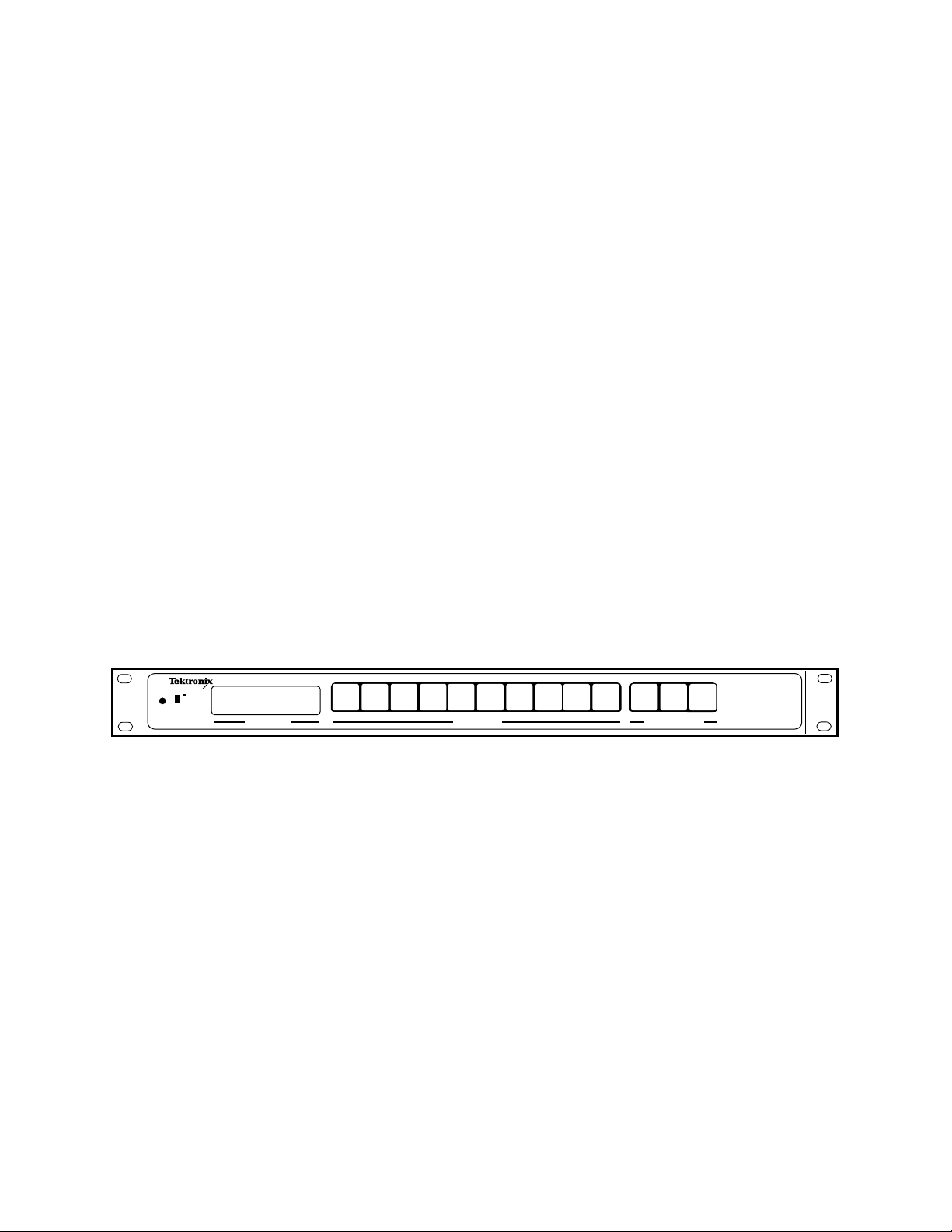
Figure 1-1. Performer-HD Router
12345678910
High Definition Background
HDTV is a form of digital television, which for home delivery uses MPEG-2
compressed video and Dolby AC-3 compressed audio. HDTV contains at
least twice the resolution of existing analog broadcast television (NTSC,
PAL, and related formats) in both the horizontal and vertical directions
(400% total increased resolution). HDTV is also presented at a 16:9 aspect
ratio, compared to existing analog broadcast’s 4:3 ratio, providing 33%
more picture area.
Related to HDTV is HD serial digital video. For full resolution broadcast,
HD serial digital video is fed to an encoder at the broadcast station which
compresses the video, combines it with compressed audio, and passes the
resultant digital signal to the transmitter for public consumption.
Input Selection
Video
CH 1/2A2CH 3/4
Breakaway/ProtectStatus/Display
A2
CH 3/4
Grass Valley
Performer-HD
VAA
A1
Performer-HD Instruction Manual 1-1
Page 16

Section 1 — Overview
The biggest technical difference between standard definition (SD) serial
digital video and HD serial digital video is the data rate. HD video has a
data rate 5.5 times (1.485 GBits/sec) that of SD video. HD video intercon-
nections use 75 ohm coax, like SD video, but the correct cables must be used
and cable runs will be limited. Connectors and patch panels must be spe-
cially constructed for HD rates to minimize signal degradation.
Several different HD video resolution and frame rates exist. Probably the
most widely supported formats are 1920x1080 interlaced at 30 frames per
second (1080i) , and 1280x720 progressive (720p) at 60 frames per second.
System Level Architecture
System Level Architecture addresses the configuration of your system and
how the signal flows.
The Performer-HD router is a three matrix frame. The video matrix switch-
es 10 Inputs to a single dual Output. The two audio matrices each switch 10
Inputs to a single 2 channel stereo Output.
The unit is a captive frame that does not require additional cooling.
10
Inputs
Video
1
Output
Dual (Identical)
Signals
10
Inputs
Audio1
AES
1
Output
Channel 1
Dual (Identical)
Signals
Channel 2
10
Inputs
Audio2
AES
1
Output
Channel 3
Dual (Identical)
Signals
Channel 4
Figure 1-2. Performer-HD System Signal Flow
1-2 Performer-HD Instruction Manual
Page 17

Specifications
Specifications
Table 1-1 contains specifications for the Performer-HD router.
Table 1-1. Performer-HD Specifications
Matrices
Serial Digital Video One 10x1
Audio Two 10x1 AES/EBU
Video/Data Inputs
Type Serial Digital conforming to SMPTE 292M or 10Mbps to 700 Mbps (non-
Impedance 75 Ohm
Quantity 10 Non Looping
Connector 75 Ohm BNC
Return Loss >15 dB to 1.485 GHz
Cable Equalization Automatic for up to 100m of Belden 1694A @ 1.485 Gbps
Video/Data Outputs
Type Serial Digital conforming to SMPTE 292M or 10Mbps to 700 Mbps (non-
Impedance 75 Ohm
Quantity 1 Dual
Connector 75 Ohm BNC
Return Loss >15 dB to 1.485 GHz
Audio/Data Inputs
Type Serial Digital conforming to standard AES3-1992 (ANSI S4.40-1985)
Impedance 75 Ohm, ±5%, 100KHz to 6MHz (BNC connector)
Quantity 10 per Audio Matrix (20 Total)
Level 400mV <signal level <7Vp-p balanced
Connector Type Unbalanced 75 ohm BNC
Audio/Data Outputs
Type Serial Digital conforming to standard AES3-1992 (ANSI S4.40-1985)
Quantity 1 dual per AES matrix
Level 1.0Vp-p ±10% into 75 Ohm BNC Connector
Connector Type Unbalanced 75 ohm BNC
Operational Modes/Performance
Video Path Delay Span 6.60nS +/- 0.5nS, Reclocked.
Data Rates Supported 1.485 Mbs reclocked or10Mb/sec to 700Mb/sec non reclocked
Interface Connectors
Type RS422 or RS232 25-pin Female D
Quantity 2
reclock mode)
reclock mode)
5.75nS +/- 0.5nS, Non Reclocked
Performer-HD Instruction Manual 1-3
Page 18

Section 1 — Overview
≤
Table 1-1. Performer-HD Specifications
Frame Power
Connector Type IEC Filtered AC connector
Quantity 1
Operational Range 10-240 VAC, 50/60Hz
Frame Power Consumption
Mechanical
Dimensions 1RU Frame 4.45 x 48.3 x 25.4 cm
Weight 6.75 kg
Environmental
Operating Temperature 0 to 40 degrees Centigrade ambient
Relative Humidity 0 to 90% non-condensing
16W
(1.75“ H x 19“ W x 10“ D)
(15 lbs)
1-4 Performer-HD Instruction Manual
Page 19

Installation
Introduction
The Performer-HD needs to be configured, to have the buttons labeled, to
be secured in a rack, to have cables attached, and to have power applied be-
fore it is ready for operation.
Dip Switch Configurations
Dipswitch banks identified as S1, S2, S3, and S4 are located under a remov-
able panel on the top of the Performer-HD. Figure 2-1 shows the location
and default settings of the dipswitch banks.
Section
2
S3
OPEN
Master
S1
123456
78
123456
OPEN
78
123456
OPEN
123456
OPEN
1
xxxx_xx_x
Figure 2-1. Dip Switch Location and Access Panel
78
78
S2
S3
OPEN
S4
Slave
S1
123456
78
123456
OPEN
78
123456
OPEN
123456
OPEN
78
78
S2
S4
2
Performer-HD Instruction Manual 2-1
Page 20

Section 2 — Installation
Figure 2-2 shows the dipswitch settings for a Performer-HD being used
with a Performer Remote Control Panel
.
Performer-HD
HD Vid
Present Reclock
V A1 CH1/2
On
Off
12345678910
A2 CH2/3
Input Selection
S3
S1
123456
123456
Video
123456
Breakaway/ProtectStatus/Display
A1
CH 1/2A2CH 3/4
78
Grass Valley
A2
Performer-HD
CH 3/4
VAA
S2
OPEN
O
78
OPEN
123456
78
OPEN
78
S4
OPEN
Performer Remote Control Panel (rear)
Dip Switch Settings
AC In
197531
A2 Out
AES/EBU 2 In
108642
2
197531
A1 Out AES/EBU 1 In
108642
2
197531
Option
V Out
Remote
108642
2
Video In
1
25
13
Performer
9 pin
Female
RS485 (+) 3
RS485 (-) 8
14
1
Performer-HD
25 pin
Male
1 RS485 (+)
2 RS485 (-)
GND (S) 9
18 GND (S)
Cable (max 2000'/610m)
User fabricated
Figure 2-2. Performer Remote to Performer-HD
2-2 Performer-HD Instruction Manual
Page 21

Dip Switch Configurations
Figure 2-3 shows the dipswitch settings for a Performer-HD being con-
trolled by a PC.
Performer-HD
HD Vid
Present Reclock
V A1 CH1/2
On
Off
12345678910
A2 CH2/3
Input Selection
Video
Breakaway/ProtectStatus/Display
A1
CH 1/2A2CH 3/4
Grass Valley
A2
Performer-HD
CH 3/4
VAA
Baud 9600
Data Bit 7
Parity Odd
Stop 1
PC (rear)
PC
25 pin
Female
TXD 2
25
S3
OPEN
S1
123456
78
123456
OPEN
78
123456
OPEN
123456
OPEN
78
78
S2
S4
Dip Switch Settings
AC In
197531
A2 Out
AES/EBU 2 In
108642
2
197531
A1 Out AES/EBU 1 In
108642
2
1
1
197531
Option
V Out
Remote
2
14
Video In
108642
25
13
Performer-HD
25 pin
Male
16 RXD
RXD 3
GND 7
3 TXD
18 GND
Cable (max 50'/15.25m)
Figure 2-3. PC to Performer-HD
Performer-HD Instruction Manual 2-3
Page 22

Section 2 — Installation
Figure 2-4 shows the dipswitch settings for a Performer-HD being con-
trolled by a PC via modem.
Performer-HD
HD Vid
Present Reclock
V A1 CH1/2
On
Off
12345678910
A2 CH2/3
Input Selection
Video
Breakaway/ProtectStatus/Display
A1
CH 1/2A2CH 3/4
Grass Valley
A2
Performer-HD
CH 3/4
VAA
Baud 1200
Data Bit 7
Parity Odd
Stop 1
PC (rear)
25
SCP
25 pin
Female
Disable or turn off
S3
modem response codes
to terminal, or select the
mode which sends them
OPEN
as numbers; disable or
turn off command
character echo.
Modem
AC In
1
25
Modem
25 pin
Male
1
25
Modem
25 pin
Male
Dip Switch Settings
197531
A2 Out
AES/EBU 2 In
108642
2
1
S1
123456
78
197531
A1 Out AES/EBU 1 In
2
123456
OPEN
78
108642
123456
OPEN
123456
OPEN
Option
V Out
Remote
14
1
Performer-HD
25 pin
Male
78
S2
78
S4
197531
Video In
108642
2
25
13
TXD 2
RXD 3
GND 7
2 RXC
3 TXD
7 GND
Cable (max 50'/15.25m)
TXD 2
RXD 3
GND 7
16 RXD
3 TXD
18 GND
Cable (max 50'/15.25m)
Figure 2-4. PC to Performer-HD via Modems
2-4 Performer-HD Instruction Manual
Page 23

Performer-HD ASCII
Table 2-1 provides an example of a Performer ASCII string used to control
a Performer-HD via a PC. The command string will switch video input
number 5 on all levels of the Performer-HD (video, audio1, and audio2).
■
Preset string = ^M007D000501
■
Take string = ^M0003T01
Table 2-1. Performer-HD ASCII Command String
Preset String
ASCII Description
Dip Switch Configurations
Byte 1 ^M carriage return
Byte 2 00 Performer address
Byte 3 07 number of data string characters
CMD D data preset, source to destination
Byte 4 00 level, 00 = all levels
Byte 5 05 input selection
Byte 6 01 output selection
Take Strings
Byte 1 ^M carriage return
Byte 2 00 Performer address
Byte 3 03 number of data string characters
CMD T take the specified destination
Byte 4 01 output selection
Performer-HD Instruction Manual 2-5
Page 24

Section 2 — Installation
Vertical Interval Strobe Selection
Performer generates its own Vertical Interval strobe, which times the
switching of video so that switching occurs within a region of each video
field when there is no active video. Performer-HD generates this from look-
ing at the parallel video data, extracting vertical interval timing informa-
tion and sending out a pulse at a specific time during vertical interval. The
DIP switch S4 is used to tell the Performer-HD which line to switch on. The
choices are lines 1, 5, 6, 7, 8, and 9; corresponding to lines 563, 567, 568, 569,
570, and 571 in the second field.
To change the vertical interval strobe setting:
1.
Locate switch S2, segments 2, 7, and 8.
Set for one of the three following conditions:
2.
●
STANDALONE
output from pin 4 of REMOTE connector: Open segments 2, 7, and 8
●
MASTER
—To provide External Strobe from pin 4 of the REMOTE
connector while using Internal Strobe: open segment 7;
ment 8. This is the Factory setting.
●
SLAVE
—To receive External Strobe on pin 4 of the REMOTE connec-
tor:
Close
without sync information.
CAUTION
3.
Do not set segments 7 and 8 to the “C” closed/ON position. This may cause a
system malfunction.
Locate switch S4 and select a line to switch using Table 2-2. Line 1 (563)
is default.
Table 2-2. Dipswitch S4 Settings
Line
Selected
12345678
—For Internal Strobe without providing external strobe
Close
seg-
segment 2 and 7;
S4 Switch Position
open
segment 8. This is for video signals
1 (563) CCCCCOOO
5 (567) OCOCCOOO
6 (568) COOCCOOO
7 (569) OOOCCOOO
8 (570) CCCOCOOO
9 (571) OCCOCOOO
2-6 Performer-HD Instruction Manual
Page 25

Switch Reference
Table 2-3 lists potential settings and effects for dip switches used to config-
ure the Performer. Address and Starting Level default values are both zero
(0). O = an
Table 2-3. Switch Reference, S1, 2, and 3 in Performer Switcher
Effect Switch
7 Data Bits S3 C
8 Data Bits S3 O
300 Baud S3 O O O `
600 Baud S3 O O C
1200 Baud S3 O C O
2400 Baud S3 O C C
4800 Baud S3 C O O
9600 Baud S3 C O C
19.2K Baud S3 C C O
38.4K Baud S3 C C C
76.8K Baud S3 O O O
No Parity S3 O O
Even Parity S3 O C
Odd Parity S3 C O
VI Internal, send external S2 O C
VI Internal, don’t send external S2 O O
VI S2 C 0
a
Address
10XL ASCII S1 8 4218421
SMPTE 3245-E S2 OOOO
Perf ASCII S2 OOOC
100/110, Always S2 OCOO
100/110, Conditional S2 OCOC
Loopback Test S2 CCOO
Normal S3 O
19 x 1 Secondary S3 C
a
Address values are cumulative and are added into the total when the switch is in the Closed (ON) position. De-
fault address offset is 000.
open
or
OFF
switch segment; C = a
S1 1286432168421
Dip Switch Configurations
closed
or ON switch segment
Segments
1
2345678
Selectable for ASCII and Model 200 protocols
only. Other protocols are always 8 data bits.
.
Performer-HD Instruction Manual 2-7
Page 26

Section 2 — Installation
Switcher Polling Address
Serial Communications Protocol Selection
Performer will accept a polling address from 0 to 255. A polling address is
necessary if more than one switcher is being controlled by a single controller. The full address range is not available to all protocols. Refer to the list
below for protocol address ranges:
■ Performer ASCII Full Range
■ GVG Model 100 or 110 Full Range
■ SMPTE 3245-E 40-255 (28H-FFH)
Performer is designed to allow serial control from multiple sources. Several
communications protocols are serviced; RS232, ASCII and SMPTE are
available by setting the proper switches. Protocols and their applications
are listed in Table 2-4.
To set up a protocol, select protocol, message parity, bit rate, and switcher
polling address. For ASCII protocols, also set serial port data bits at 7 or 8.
For other protocols, the data bits are automatically set at 8. Performer serial
port stop bits are automatically set at 1.
Table 2-4. Protocols and Applications
Protocol Application
Performer Remote Control
Performer ASCII
GVG Model 100 and 110
SMPTE 3245-E Remote Control System
for Television Equipment
Use this protocol when you are controlling the Performer from
the Performer Remote Control Panels.
Straightforward control of the Performer from a host computer,
using standard ASCII characters.
Use this protocol when you are controlling the Performer from
the Grass Valley Model 100 or 110 Production Switcher.
Use this protocol when you are controlling the Performer from
a host computer using SMPTE 3245-E.
2-8 Performer-HD Instruction Manual
Page 27

Button Labeling
Film chips imprinted with standard source names and clear button caps are
included with Performer. Select names which suit your requirements and
install the chips and caps as illustrated.
Button Labeling
A1 CH1/2
V
STATUS DISPLAY
Figure 2-5. Button Labeling
A2 CH1/2
Film Chip
VTR
27
IN
Install caps so that the
fingernail slots are at top and
bottom.
Performer-HD Instruction Manual 2-9
Page 28

Section 2 — Installation
Rack Layout
Performer-HD is designed to mount in a 19-inch equipment rack. The
frame occupies 1 RU (Rack Unit, 1.75 inches/4.45 cm) of vertical space.
Figure 2-6 shows how to mount the frame in the rack. The rear rack mount-
ing bracket is supplied with the frame. Use the mounting bracket to support cable weight on the back of the Performer-HD.
Grass Valley
A2
A2
A1
Performer-HD
CH 3/4
CH 3/4
Video
CH 1/2
HD Vid
Present Reclock
V A1 CH1/2
On
Off
Status/Display
Input Selection
12345678910
A2 CH2/3
Breakaway/Protect
VAA
Figure 2-6. Rack Installation
There are many different rack manufacturers. The size and thread pitch of
mounting screws varies. These screws must be supplied by the rack manufacturer or purchased locally.
When installing a Performer-HD router in a rack with other devices keep
the Performer-HD router out of the airflow path of vertically cooled components.
2-10 Performer-HD Instruction Manual
Page 29

Cabling
Cabling
AC In
197531
A2 Out
2
AES/EBU 2 In
108642
197531
A1 Out AES/EBU 1 In
108642
2
Option
Remote
19753 1
V Out
108642
2
Video In
AC In Audio2 Audio2 Audio1 Audio1 Option & Video Video
Out In Out In Remote Out In
Figure 2-7. Performer-HD Cabling Connections
D Connector Cabling
The 25-pin, female D connectors provide points of connection.
The
Remote connector can be used for:
■ Remote control panel (RS485)
■ RS232, RS422 interface
■ External Vertical Interval Strobe
The
Option connector can be used for:
■ Joystick Override/Custom control and Tally Relay connection when a
Tally module option is installed.
Table 2-5 shows the pin numbering and lists the signal-to-pin number cor-
relation for the
CAUTION If you are adding your own control device, using RS422 or RS485 control, you
may need to construct a connecting cable.
Both RS422 and RS485 control require terminating resistors installed at the
end of the RS422 or RS485 bus.
Remote and Option 25-pin female D connectors.
Performer-HD Instruction Manual 2-11
Page 30

Section 2 — Installation
Connector Pin Remote Pin Option
D-25 Female
Pin 1
Pin 13
a
/ = Active Low
Table 2-5. Remote 25-Pin D Connector Pinouts
13 VA (bit A of 4-bit binary video status 1 Switch 1
25 VB (bit B of 4-bit binary video status 2 Switch 2
24 VC (bit C of 4-bit binary video status) 3 Switch 3
Pin 14
Pin 25
23 VD (bit D of 4-bit binary video status) 4 Switch 4
5 AA (bit A of 4-bit binary audio status) 5 Switch 5
6 AB (bit B of 4-bit binary audio status) 6 Switch 6
7 AC (bit C of 4-bit binary audio status) 7 Switch 7
8 AD (bit D of 4-bit binary audio status) 8 Switch 8
a
(bit O of 5-bit binary source select)
19 0/
21 A/ (bit A of 5-bit binary source select) 10 Switch 10
22 B/ (bit B of 5-bit binary source select) 11 Switch V (Video Only)
9 C/ (bit C of 5-bit binary source select) 12 SwitchA1 (Audio 1 Only)
20 D/ (bit D of 5-bit binary source select) 13 Switch A2 (Audio 2 Only)
12 KEY ON/ (active low - any button press) 14 GPI (Switch) Common, +5V
10 A ONLY/ (active low - audio only select) 15 Tally Relay 1
11 V ONLY/ (active low - video only select) 16 Tally Relay 2
1 TX RS422+ (RS485 <+>) 17 Tally Relay 3
2 TX RS422– (RS485 <->) 18 Tally Relay 4
14 RX RS422+ 19 Tally Relay 5
15 RX RS422– 20 Tally Relay 6
3 TX RS232 21 Tally Relay 7
16 RX RS232 22 Tally Relay 8
4 VI Strobe 23 Tally Relay 9
18 Ground (RS485 <S>) 24 Tally Relay 10
17 ≈ +20V DC 25 Tally Common
9 Switch 9
Matrix BNC Cabling
Input Sources and output Destinations are cabled using 75 Ohm BNCs. All
outputs are duplicated. Any output that is not being used has to be terminated with a 75 Ohm terminator.
2-12 Performer-HD Instruction Manual
Page 31

Power
Power
When setup, mounting, and cabling is complete, apply power to the system
to perform an operational check.
To power up and perform an operational check:
1. Connect an AC cord to the AC IN connection on the back of the
Performer-HD.
2. Connect the AC line cord from switcher to an AC main. Performer-HD
does a self-test.
Note To accelerate the displays press any of the buttons 1 through 8 on the Perform-
er-HD front panel. To skip the self-test entirely press any other button.
Status information is displayed in the following order:
Table 2-6. Performer-HD Self-Test
Start-up Display Protocol or Test
88 88 88 LED test
rE SE t Warm reset
10 20 TEN-20 compatible
7 68 00 Baud rate
PA r n8 No parity / 8 data bits
SO 1- 10 No source offset
DE St 01 No destination offset
LV L1 23 No level offset
SL AV E0 Master mode
NT SC NTSC video source
Performer-HD Instruction Manual 2-13
Page 32

Section 2 — Installation
2-14 Performer-HD Instruction Manual
Page 33

Section3
Operation and Maintenance
Introduction
The Performer-HD will select any one of the ten input sources for output
on its single destination. Protects can be set so that the current selection is
locked and prevented from accidental change.
It is possible to control a Performer-HD from a 110 Production Switcher, or
from an RS232 or RS422-compatible terminal or computer. Control from a
Production Switcher is invisible to the Production Switcher operator (providing the Production Switcher is appropriately equipped and configured).
Use of RS232 or RS422 control via a terminal or computer is dependent
upon configuration and connection requirements. The Serial Protocol Descriptions provide the technical information needed for control from production switchers and terminals.
Performer-HD Front & Remote Panel Operation
When using a Performer-HD with any remote controller, the PerformerHD is the master panel; it can remove protects placed by the remote controller. Except for this difference, the following operating descriptions apply to both the local integrated control panel and the remote control panel.
The Performer-HD panel display does not tally Source, destination, and
level offsets. When several panels used on a bus are used to control several
Performers, other means (such as labeling) must be used to identify the
Performer associated with each panel.
HD Vid
On
Off
Present Reclock
V A1 CH1/2
A2 CH2/3
Figure 3-1. Performer-HD Front
12345678910
Input Selection
Video
CH 1/2A2CH 3/4
Breakaway/ProtectStatus/Display
A1
Performer-HD Instruction Manual 3-1
A2
CH 3/4
Grass Valley
Performer-HD
VAA
Page 34

Section 3 — Operation and Maintenance
Data Rate Mode
The Performer-HD can handle HDTV signals of SMPTE 292M at 1.485
Gbps and in bypass (non-reclocking) mode can pass data rates from 10
Mbps to 700 Mbps. When HDTV signals are present the
will be lit. When using the Performer-HD with data rates of 10 Mbps to 700
Mbps turn reclocking off.
HD Vid
Present Reclock
HD Vid Present LED
On
Off
Figure 3-2. Data Rate Mode Selection
Audio Follow Video
An Audio Follow Video (AFV) take is one in which Video, Audio 1 (Channel 1/2), and Audio 2 (Channel 3/4) all come from the same input.
To perform an AFV take:
■ Press the button below the number of the desired source.
For example, if you press the button
below source number 5, the number 5
input for Video, Audio 1, and Audio 2
will be taken to the output.
Figure 3-3. AFV Take Source 5
5
Following the action above, the Status Display would indicate Video, Audio 1 (Channel 1/2), and Audio 2 (Channel 3/4) deriving from source 5.
3-2 Performer-HD Instruction Manual
Page 35

Performer-HD Front & Remote Panel Operation
Breakaway
VA1A2
STATUS DISPLAY
Figure 3-4. Status Display for AFV Take on Source 5
02
A breakaway take is one in which the source number of at least one level
(Video, Audio1), or Audio2) is different from the source number of one or
both of the other levels. In the following example, we assume a beginning
status in which all levels are deriving from source 5.
VA1A2
STATUS DISPLAY
Figure 3-5. Breakaway Tale on Source 5
02
Many users are accustomed to holding down the Breakaway button while
making a breakaway selection. Performer-HD simplifies this operation by
allowing a press and release of the Breakaway button, followed by source
selection.
Video Only
To change the video source only:
1. Press the Breakaway button labeled Video
Figure 3-6. Video Source Change
The V window will display dashed underlines awaiting entry. (to cancel the breakaway, press the Breakaway button a second time.)
VA1A2
STATUS DISPLAY
02
Performer-HD Instruction Manual 3-3
Page 36

Section 3 — Operation and Maintenance
2. Press the button of the desired source
The Status Display will now indicate that video is deriving from the selected source (8 in the example) while Audio 1 and Audio 2 continue
from source 5.
Figure 3-7. Video Source 8 Audio Source 5
Audio1 Only
To change the Audio1 source only:
1. Press the Breakaway button labeled A1
The A1 window will display dashed lines awaiting entry. (If you wish
to cancel the breakaway, press the Breakaway button a second time.)
VA1A2
Figure 3-8. Audio1 Source change
VA1A2
STATUS DISPLAY
STATUS DISPLAY
03
04
2. Press the button of the desired source
The Status Display will now indicate that Audio1 is deriving from the
newly selected source; Video and Audio2 continue as before, for example, select A1, source 4.
VA1A2
STATUS DISPLAY
Figure 3-9. Video Source 8, Audio1 Source 4, Audio2 Source 5
04
3-4 Performer-HD Instruction Manual
Page 37

Audio2 Only
To change the Audio2 source only:
1. Press the Breakaway button labeled A2
The A2 window will display dashed lines awaiting entry. (To cancel the
breakaway, press the Breakaway button a second time.)
Performer-HD Front & Remote Panel Operation
VA1A2
STATUS DISPLAY
Figure 3-10. Audio2 Source Change
2. Press the button of the desired source
05
The Status Display will now indicate that Audio2 is deriving from the
newly selected source; Video and Audio1 continue as before. For example, select A2, source 3.
VA1A2
STATUS DISPLAY
Figure 3-11. Video Source 8, Audio1 Source 4, Audio2 Source 3
05
Performer-HD Instruction Manual 3-5
Page 38

Section 3 — Operation and Maintenance
Protect
To protect your source selection from being changed:
■ Press and release all three Breakaway buttons simultaneously
The Performer-HD is now protected. Further button presses will have no
effect (until the protect is released). The display will alternate between displaying the selected sources and displaying the panel’s protected status, as
illustrated below.
VA1A2
OR
STATUS DISPLAY
Protect placed by local front panel
Figure 3-12. Protected Status Display
VA1A2
STATUS DISPLAY
Protect placed by a Remote
Panel or external device
Alternating with:
VA1A2
STATUS DISPLAY
Figure 3-13. Sources Selected Display
05
To release the protect:
■ Press and release all three Breakaway buttons simultaneously.
The panel will revert to normal operation.
The integral control panel of the switcher can remove protects placed by remote panels or external devices. External devices cannot remove a protect
placed by the integral control panel.
3-6 Performer-HD Instruction Manual
Page 39

Joystick Override Operation
Joystick override control is used primarily when several camera operators
are using a common monitor to check the adjustment of their cameras. Each
camera control unit (CCU) has a momentary contact switch which is wired
to the
OPTION connector of Performer-HD. (See the Installation section of this
manual.) The Performer-HD output is connected to a common video monitor. Joystick override operations follows.
An initial source is sent to the monitor using the Performer-HD control
panel. This will be the default source.
To use the Joystick Override:
1. Press and hold the switch on the CCU to check the signal coming out of
the camera. As long as the switch is held down, the video of the
associated camera is displayed on the monitor.
Joystick Override Operation
2. Release the switch to return to the default video. The default video
source becomes the current selection on the Performer-HD control
panel.
Camera 1
Monitor
CCU
Camera 2
CCU
Cameras 3 - 9
Camera 10
CCU
Control
Video Signal
Figure 3-14. Joystick Override
OPTION
Performer-HD Instruction Manual 3-7
Page 40

Section 3 — Operation and Maintenance
Serial Protocol Descriptions
Performer-HD supports several serial communications protocols. Switches
inside the Performer-HD frame must be properly set depending upon
which protocol you will be using.
The following pages provide examples of messages in the various protocols and describe any operational conditions which must be met when using a production switcher protocol. Table 3-1 provides a cross-reference
between Hexadecimal and ASCII characters.
Any protocol which allows a protect must refresh the protect within a constant 30-second window or the protect will be removed. In the following
descriptions, Protocol Error, Parity, and Framing errors are mentioned.
When Protocol Error is called, the switcher displays
When Parity or Framing errors are received, the switcher displays
half a second.
ERR P for half a second.
ERR R for
3-8 Performer-HD Instruction Manual
Page 41

Serial Protocol Descriptions
Table 3-1. Hexadecimal - ASCII Cross-Reference
HEX CTRL CHARACTERS HEX CH HEX CH HEX CH
00 ^@ NUL 20 SP 40 @ 60 ‘
01 ^A SOM 21 ! 41 A 61 a
02 ^B STX 22 “ 42 B 62 b
03 ^C ETX 23 # 43 C 63 c
04 ^D EOT 24 $ 44 D 64 d
05 ^E ENQ 25 % 45 E 65 e
06 ^F ACK 26 & 46 F 66 f
07 ^G BEL 27 ' 47 G 67 g
08 ^H BS 28 ( 48 H 68 h
09 ^I HT 29 ) 49 I 69 i
0A ^J LF 2A * 4A J 6A j
0B ^K VT 2B + 4B K 6B k
0C ^L FF 2C , 4C L 6C l
0D ^M CR 2D - 4D M 6D m
0E ^N SO 2E . 4E N 6E n
0F ^O SI 2F / 4F O 6F o
10 ^P DLE 30 0 50 P 70 p
11 ^Q DC1 31 1 51 Q 71 q
12 ^R DC2 32 2 52 R 72 r
13 ^S DC3 33 3 53 S 73 s
14 ^T DC4 34 4 54 T 74 t
15 ^U NAK 35 5 55 U 75 u
16 ^V SYN 36 6 56 V 76 v
17 ^W ETB 37 7 57 W 77 w
18 ^X CAN 38 8 58 X 78 x
19 ^Y EM 39 9 59 Y 79 y
1A ^Z SUB 3A : 5A Z 7A
1B ^[ ESC 3B ; 5B [ 7B {
1C ^\ FS 3C < 5C \ 7C |
1D ^] GS 3D = 5D ] 7D }
1E ^^ RS 3E . 5E ^ 7E
1F ^_ US 3F ? 5F _ 7F DEL
Performer-HD Instruction Manual 3-9
Page 42

Section 3 — Operation and Maintenance
Performer-HD ASCII Protocol
Performer-HD ASCII allows control of the Performer-HD from a host terminal or computer using standard ASCII characters. Multiple Performers,
each assigned a unique address, may be controlled over a common RS422
bus. All characters are 7-bit ASCII (the eighth data bit out of the PerformerHD port is ignored). A ninth data bit may be used for parity if desired.
Command Line
A command line consists of series of bytes in the following format:
<CR><Adr Hi><Adr Lo><Len Hi><Len Lo><Data>
All bytes are hex ASCII (characters 0-9 [30H-39H] and A-F [41H-46H]), except for <CR>. A hex ASCII character specifies 4 bits or 1 nibble of information and is used in high/low pairs to specify a complete byte of
information. Received ASCII nulls (00H), spaces (20H), and line feeds
(0AH) are ignored and are not included in the byte count.
Command bytes have the following values:
Table 3-2. Command Bytes Values
Command Description
<CR> REQUIRED carriage return character (0DH)
<Adr Hi> 0-F, high nibble of Performer-HD switch 1 address
<Adr Lo> 0-F, low nibble of Performer-HD switch 1 address
<Len Hi> 0-F, high nibble of byte count for <Data>
<Len Lo> 0-F, low nibble of byte count. Count must not exceed 251 (FBH).
<Data>
0-9, A-Z. Zero or more command strings (see Command Strings).
Number of <Data> characters is <Len>
If the <Adr Hi> <Adr Lo> value is different from the value set at Performer-HD switch S1, the command and all subsequent characters are ignored by the Performer-HD until a new message is initiated using a
carriage return. The carriage return purges previously received data, and
must start each command line.
If a carriage return is received before a command string is complete, the
Performer-HD will display
play.
ERR P will also be displayed on receipt of parity/overrun, checksum,
ERR P for about half a second in the status dis-
or syntax errors.
3-10 Performer-HD Instruction Manual
Page 43

Command Strings
Commands, <Data>, must consist of exactly <Len Hi> <Len Lo> characters forming a string of zero or more commands. Each command must
consist of a single <CMD> character identifying the command, followed by
any <Data> required by that command.
The following command characters and data are supported.
Table 3-3. Command Characters
<Cmd> <Data> Description
D (44H) <Sources> Data preset, source to destination
A (41H) (None) All-destination Take of current preset matrix
T (74H) <Dest> Take of specified destination only
P (50H) <Dest> Protect specified destination (must be refreshed every 30 seconds)
C(43H) <Dest> Clear protect on specified destination
Serial Protocol Descriptions
R (52H) (None) Reset Performer-HD to factory defaults
Q (71H) <Dest> Query for status of specified destination
S (53H) <Status> Status response
Except for the S command, all of the above are sent by the controller to the
Performer-HD. The S command is sent by Performer-HD to the controller
in response to a Q (Query for status) command. Performer-HD generates a
response to the Q command only.
The R command (Reset) causes Performer-HD to initialize just as if power
had been turned off, then on. No data should follow the R command.
The D command allows matrix crosspoints to be preset but not actually activated. A subsequent A or T command causes preset values to take effect.
This can be useful when you wish to switch several switchers on a particular video field and thus have no time to send several messages. The D command is used to set up the switchers; then a series of short A commands to
each switcher initiates the switch.
The A and T commands both set all levels. D commands should be sent to
set the values of any level which are not to be the same as in the last A or T
command (source 1 initially).
Performer-HD Instruction Manual 3-11
Page 44

Section 3 — Operation and Maintenance
Data
Table 3-4 indicates the data to be inserted following a command character,
Table 3-4. Data Types
Data Type Command String Elements
<Sources> <Lvl Hi> <Lvl Lo> <Src Hi> <Src Lo> <Dest Hi><Dest Lo>
<Dest> <Dest Hi> <Dest Lo>
<Status> <PC> <Lvl Hi> <Lvl Lo> <Src Hi> <Src Lo><Dest Hi> <Dest Lo>
Table 3-5 indicates the command string elements.
Table 3-5. Command String Elements
Element Description
<PC> P(50H) if protect active, C(43H) if protect clear
<Lvl Hi> 0-F, high nibble of level
<Lvl Lo> 0-F, low nibble of level
<Src Hi> 0-F, high nibble of source
<Src Lo> 0-F, low nibble of source
<Dest Hi> 0-F, high nibble of destination
<Dest Lo> 0-F, low nibble of destination
Table 3-6 indicates the level settings set by <Lvl Hi> and <Lvl Lo>.
Table 3-6. Level Settings
LvL Hi LvL Lo Result
0 0 All Levels (AFV)
0 1 Video
0 2 Audio 1
0 3 Audio 2
3-12 Performer-HD Instruction Manual
Page 45

Serial Protocol Descriptions
Table 3-7 indicates the source settings set by <Src Hi> and <Src Lo>.
Table 3-7. Source Settings
Src Hi Src Lo Result
0 0 No Source
0 1 Source selection 1
0 2 Source selection 2
0 3 Source selection 3
0 4 Source selection 4
0 5 Source selection 5
0 6 Source selection 6
0 7 Source selection 7
0 8 Source selection 8
0 9 Source selection 9
0 A Source selection 10
Table 3-8 indicates the destination setting set by <Dest Hi> and
<Dest Lo>.
Table 3-8. Destination Setting
Dest Hi Dest Lo Result
0 1 Destination 1 (Performer -HD has only 1 destination)
Examples
In the following examples the Performer-HD address is set to 3C hex.
To preset level 3 of source 5 to destination 1, send these characters:
<CR>3C07D030501
In the example, 3C= <Adr>, 07=<Len>, and D030501= <Data>.
To take the preset values to the switcher output, send these characters:
<CR>3C01A
or, use the T command:
<CR>3C03T01
Performer-HD Instruction Manual 3-13
Page 46

Section 3 — Operation and Maintenance
To combine preset and take into a single command:
<CR>3C08D030501A
To query Performer-HD:
<CR>3C03Q01
If all levels were connected to source 3 and protected, the query response would be:
<CR>3C08SP000301
(Where level 00 indicates all levels)
If levels 1 and 3 were connected to source 10 and level 2 to source 1 and
unprotected, the response would be:
<CR>3C10SC000A01SC020101
The response contains two S commands. In the first, level 00 indicates
all levels are connected to source 10 (0A), but the second indicates that
level 2 is in fact connected to source 1 (takes precedence over the first
response). This technique reduces the number of characters in the response message by using the all levels value for the source connected
to the greatest number of levels followed by a specific message regarding sources connected to other levels.
If level 1 were connected to source 3, level 2 to 8, and level 3 not connected, the response would be:
<CR>3C18SP000301SP020801SP030001
The first S command specifies level 00, not level 01. The first S command in a status response is always for level 00 (all levels).
3-14 Performer-HD Instruction Manual
Page 47

Performer-HD Remote
This protocol provides bidirectional communication between controlling
devices and crosspoint controllers on a single shielded twisted-pair cable.
RS485 standard is used, allowing a maximum of 32 communicating devices
on the bus. The protocol supports crosspoint matrices up to 4 levels, each
99x99. When this protocol is selected, Performer-HD forces the serial port
to 76.8K baud, 8 data bits, no parity.
When selecting this protocol, note that four variations are allowed depending upon the position of switch 2, segments 6 and 5. If 6 is OPEN, each Performer-HD level (video, audio 1, audio 2) is treated as a separate level in
the protocol (independently controllable within the switcher). If 6 is
CLOSED, all three levels are treated as a single level and switch simultaneously. (A breakaway can still be executed at the switcher integral control
panel).
If segment 5 is OPEN, the switcher will be in master mode. In master mode,
Performer-HD receives, executes, and responds to commands. If segment 5
is CLOSED, the switcher will be in slave mode. In slave mode, PerformerHD receives and executes commands but does not respond on the serial
bus. Slave mode is used when it is desirable to use multiple Performers assigned to the same level and destination number. The switchers will execute commands simultaneously but only a single Performer (set to master
mode) will respond with a tally message. Only one master mode Performer
may be on any one level/destination combination at a time. Otherwise,
garbled communications due to bus collisions will result.
Serial Protocol Descriptions
Source, Level, and Destination offsets which allow you to use multiple
master mode Performers on the same bus (but not the same level and destination) are determined by Performer switch S1.
Model 110 Compatible Protocol
Performer-HD may be used as a Model 110 Production Switcher peripheral. The Performer-HD audio selection automatically follows the switching
of the Model 110 Program Bus.
Performer-HD Instruction Manual 3-15
Page 48

Section 3 — Operation and Maintenance
SMPTE 3245-E Protocol
Performer-HD may be controlled by a host computer using SMPTE 3245-E
protocol if the proper switches on the Performer-HD have been set. The
SMPTE 3245-E protocol is based on the following SMPTE standards documents:
■ Remote Control Systems for Television Production Equipment, Tech
3245-E, December 1984.
■ Remote Control Systems for Broadcasting Production Equipment: Sys-
tem Service and Common Messages, Supplement 1 to Tech 3245-E, June
1986.
■ Remote Control System for Broadcasting Equipment, Routing Switcher
Type-Specific Messages, Draft 0.1, July 1988.
Performer-HD has no non-standard communication sequences used with
the SMPTE ESCAPE sequence. If Performer-HD is selected and the SMPTE
ESCAPE character received, Performer-HD will enter the IDLE state and
call protocol error.
On reset, Performer-HD assigns itself to the SMPTE all-call group address
and clears all other group assignments.
Performer-HD does not make entries in the bus controller linkage directory. This must be handled by another device on the bus.
Performer-HD is a single virtual machine. Messages for selecting virtual
machine are NOT supported.
SMPTE standard (1984) shows the receive values for the ASSIGN state to
be 00-0F, 80-FF. This appears to be an error. It is 00-7F for deassignment and
80-FF for assignment.
SMPTE BUSY status (06H) is never returned by Performer-HD.
Protocol error is called when a protocol error occurs. Receive error is called
when a message we send is NAK’d by the bus controller or when a message
with a bad checksum is received.
3-16 Performer-HD Instruction Manual
Page 49

Serial Protocol Descriptions
SMPTE messages implemented by Performer-HD are listed in Table 3-9.
Table 3-9. SMPTE Messages Implemented by Performer-HD
Byte Mnemonic Full Name Type
00 R SNOP System Service NOP System Service
01 R RBGN Reserved Begin System Service
02 R REND Reserved End System Service
03 R SRST System Service Reset System Service
06 R BLCK Block System Service
08 T SERR System Service Error System Service
20 R CNOP Common NOP Common
21 R CRST Common Reset Common
22 R READ Read Info Fields Common
29 T CERR Common Error Common
32 T IFRE Info Field Item Response Common
3F – CEXT Common Extension Common
3F/07 R UDAT Update Common
3F/09 R MUTE Mute Common
a
40 T STUR Startup Response Type-Specific
42 R CONC Connect Crosspoint Type-Specific
43 R DISC Disconnect Crosspoint Type-Specific
46 R ???? Specific Mute Type-Specific
60 R PRST Preset Information Fields Type-Specific
a
R=Received, T=Transmitted
Performer-HD Instruction Manual 3-17
Page 50

Section 3 — Operation and Maintenance
SMPTE information fields implemented by Performer-HD are listed in
Table 3-10.
Table 3-10. SMPTE Information Fields Implemented by Performer-HD
Byte Full Name Type/Value
21 Virtual Machine Type Common, 8-bit unsigned = 05
22 Equipment Type Common, Byte Count/ASCII chars: Performer-HD\r07XXXX-00 VERS 1.0
27 Virtual Machine Status Common, 8-bit unsigned=02 (available)
41 Matrix Pointer Type-Specific, 1 byte, 00 or FF: 00=this Performer matrix; FF=all matrices
42 Level Pointer Type-Specific, 1 byte, 00-02 or FF:
43 Source Pointer Type-Specific, 2 bytes,0000-0009 or FFFF:
44 Destination Pointer Type-Specific, 2 bytes, 0000 or FFFF
46 Destinations to Source Type-Specific, 4 or 5 bytes: matrix, level, source, 0/1:
47 Sources to Destination Type-Specific, 4 or 5 bytes: matrix, level, destination, 0/1:
4A Level Configuration Type-Specific, 11 bytes:
00=video
01=audio 1
02=audio 2
FF=all levels
0000-0009=source
FFFF=all sources
0000=this Performers destination
FFFF=all destinations
0=no connection
1=next 2 bytes give destination (0000)
0=no connection
1=next 2 bytes give source (0000-0009)
matrix=00
level=00-02
min source=0000
max source=0009
min dest=0000
max dest=0000
nonexistent block count=00
SMPTE Message Processing
Message processing uses a buffer that can contain up to 200 bytes to hold
outgoing messages. All messages waiting to be sent are concatenated together into a single message block not surrounded by a Block command
(see below), which is placed in the message buffer and sent at the next message send time. The controlling machine must therefore be careful not to request too much information at one time, lest it overflow the buffer. If this
buffer does overflow before the bus controller polls and responds to the
router service request to send the data, the entire buffer contents are cleared
and replaced with a system service error (
overflow.
3-18 Performer-HD Instruction Manual
SERR) message indicating buffer
Page 51

Serial Protocol Descriptions
SERR (08, System Service Error) is also sent when a system service message
is encountered (byte code between 00 and 1F) that Performer cannot handle, or when a message that it can handle contains a bad data item.
CERR (29, Common Error) is sent when a common message is encountered
(byte code between 20 and 3F) that Performer cannot handle, or when a
message that it can handle contains a bad data item.
Any
SERR and CERR that is generated as a result of a bad value in the mes-
sage or inability to perform the message function contains all data bytes of
the message, from the command keyword up to the data byte at which the
error was detected.
Since the type-specific messages do not have an error response message,
CERR is sent when a type-specific message is received that has an error in it.
IFRE (32, Information Field Item Response) is sent in response to a READ
message or a previous UPDATE request.
STUR (40, Startup Response) is sent when the router is powered up or reset.
The SMPTE standard document, on page 37, shows in Figure 11c that a
Block keyword can surround a group of messages, and that additional messages can both precede and follow the block of data in the same supervisory-level message block. The SMPTE Supplement 1 to 3245-E says, on page
15 under the description of the Block command, that the command shall be
used on every occasion where message concatenation is employed. These
two seem to conflict with each other. Performer sends outgoing messages
without a Block command, and parses incoming messages with or without
Block commands.
The Specific Mute message definition does not explicitly say that more than
one information field can be supplied, wrapped in a Begin/End construct.
However, since this is the usual definition in other parts of the standard,
Performer-HD allows that construct.
Likewise, the Preset message definition does not explicitly say that more
than one information field name/value pair can be supplied, wrapped in a
Begin/End construct. This construct is allowed by Performer.-HD
The following I/F names can be used in a Preset message: Matrix, Level,
Source, and Destination pointers. In particular, note that sources-to-destination and destinations-to-source may not be used.
The Preset message will not allow the Matrix, Level, Source, or Destination
pointers to be set to values that are invalid for this matrix. The SMPTE standard does not say whether invalid I/F values can be set or not.
Performer-HD Instruction Manual 3-19
Page 52

Section 3 — Operation and Maintenance
The SMPTE standard does not say what should be returned for the Level
Configuration information field if the matrix pointer or level pointer is set
to an invalid value. Since Performer does not allow invalid values to be set,
this is not a problem.
The Level Configuration information is of limited usefulness because there
is no message for determining the allowed limits of the matrix pointer and
the level pointer. The router requires the matrix pointer to be 0 and the level
pointer to be between 0 and 2 (wildcard values are allowed too).
A single I/F Item Response message is sent containing all values (wrapped
in Begin/End) requested via Read or Update messages since the last such
response message was sent. Two separate Read messages back to back will
not produce two I/F Item Response messages containing the separate data
items, but rather will produce a single message containing them.
The Read message will result in all the values being read simultaneously,
just as with the SRDR (3F/11, Simultaneous Read Response) message.
The destinations-to-source and sources-to-destination information fields
are sensitive to whether or not the level, source, and/or destination pointers are set to the wildcard values (FF, FFFF). If so, reading these information
fields results in multiple I/F response values for these I/Fs; one for each
wildcard replacement combination. The SMPTE spec is a bit unclear about
how the wildcarding should apply, but this seems to be the correct way.
It is not possible to read the value of a single crosspoint, only of entire rows
or columns of the crosspoint matrix (using sources-to-destination or destinations-to-source). Setting the matrix, level, and destination pointers, and
then reading the source pointer, will not give the source connected at that
matrix/level/destination. Instead, it will give the current value of the
source pointer.
3-20 Performer-HD Instruction Manual
Page 53

Maintenance
Troubleshooting
Maintenance
If the Performer-HD is not responding to front panel selections, a power reset may correct the condition.
■ Disconnect then reconnect AC power to the unit
If the Performer-HD is responding to front panel selections but is not operating correctly:
■ Check input signals
■ Check cables and connections
■ Check reclock switch on front panel
■ Check internal setup switches (S1, S2, S3, S4)
Service
■ Verify source equipment is operating correctly
■ Check output connections
If the Performer-HD is not operating correctly, replace it with a known
good spare (if available) and contact Customer Service.
Use the information on the back of the title page to contact Customer Service. They will provide directions.
Performer-HD Instruction Manual 3-21
Page 54

Section 3 — Operation and Maintenance
3-22 Performer-HD Instruction Manual
Page 55

Glossary
1080i
An abbreviated term for a high definition
digital video signal as defined by SMPTE
274M. 1080i signals have 1920 horizontal
pixels per line, 1080 active lines, and are interlace with two fields per frame.
720p
An abbreviated term for a high definition
digital video signal as defined by SMPTE
296M. 720p signals have 1280 horizontal
pixels per line, 720 active lines, and are progressive scan.
AC-3
A transport mechanism for multi-channel
audio, as defined by ATSC specification
A-52. AC-3 is used as the audio delivery
system for DTV programs.
Analog
Use of a continuously variable signal to
convey information. Conventional Definition Television (NTSC, PAL, etc.) is analog.
Aspect
The ratio of a picture’s horizontal and vertical dimensions when correctly displayed
(16:9 for example).
Bit Rate
The number of bits per second passed from
one point to another.
Black Burst
See Color Black.
Color Black
An analog synchronizing signal consisting
o f horizontal, vertical, and color synchronizing information. This signal produces a
black screen on a Conventional Definition
television monitor.
Component Video
A video signal that keeps color and luminance information separate. RGB; Y, R-Y,
B-Y; and Y, Cr, Cb are examples of component video.
Composite Video
An encoded video signal that combines
color information with luminance information. NTSC, PAL, and D-2 are examples of
composite video.
Conventional Definition Television (CDTV)
The analog NTSC, PAL, SECAM, and related television systems.
ATSC
Advanced Television Systems Committee,
developer of the HDTV standards recommended to the FCC for adoption.
Auto Ranging
AC input range selections of 90 to 132 VAC
and 180 to 260 VAC are automatic.
Performer-HD Instruction Manual Glossary-1
Delegate
To assign panel controls to a particular operating function. Some panel controls (buttons, knobs, joystick) can affect more than
one function. The operator can choose an
alternative function by delegating the panel controls to that function (typically by
pressing or holding down a panel button).
Page 56

Deserializer
Frame Rate
A device that converts serial digital information to parallel.
Digital
Use of discrete signal levels that correspond to logic 1 or 0 to convey information.
Digital Television (DTV)
The digital television broadcasting system
that replaces analog television. DTV includes both HDTV and SDTV broadcast in
digital form using MPEG-2 compression
for video, AC-3 compression for multichannel audio, and 8-VSB modulation for
digital terrestrial transmission.
Field
One scan of an interlaced video image. In
interlace systems (1080i, for example) two
fields are required to make a complete picture (video frame) because alternate lines
are scanned. Note that on progressive systems (720p, for example), one scan contains all the image information, and so this
single scan is called a frame rather than a
field.
Field Replaceable Units
Components of a frame, matrix, switcher,
etc. that can be removed and replaced with
a spare. Field Replaceable Units are not repaired in the field and are sent to designated repair depots.
Frame
One complete scan of a video image. For
progressive video, all the lines in a frame
are scanned successively from top to bottom. For interlace video, alternate lines are
scanned, and so a frame containing all the
picture information consists of two fields.
The number of frames presented per second. Note that for interlace systems the
frame rate is half the field presentation
rate.
Framestore
A device that captures, saves, and outputs
a still video image.
GSC
Global Serial Channel
High Definition Television (HDTV)
Television with a resolution approximately
twice that of Conventional Definition Television in both the horizontal (H) and vertical (V) dimensions and a picture aspect
ratio (H x V) of 16:9.
Interlace
A system of video scanning where the odd
and even numbered lines of a picture are
presented consecutively as two separate
interleaved fields. The two fields required
to make a complete picture are called a
frame.
Jitter
An undesirable variation in the timing of
transitions in a digital signal.
MPEG-2
A video compression mechanism employed by DTV to fit the digital data into
an existing 6 MHz bandwidth transmission channel.
Parallel Digital Video
(1) Passing multiple video data bits in parallel groups along a collection of wires
(called a bus). High Definition parallel digital video (1080i and 720p) typically uses
two parallel 10 bit buses (20 bits total) operating at 74.25 MHz. In comparison, Stan-
Glossary-2 Performer-HD Instruction Manual
Page 57

dard Definition parallel digital video
employed within a device typically uses
two 10 bit buses operating at 13.5 MHz.
(2) For parallel interfaces between devices
using multi-pair cables (now obsolescent)
the two buses are combined for Standard
Definition video into one 27 MHz interface
(SMPTE 125M). The two buses remain separate for High Definition parallel interfaces
using multi-pair cables (SMPTE 274M).
Pixel
A picture element. A pixel is a digital sample of the color intensity values of a picture
at a single point.
PECL
Positive Emitter Coupled Logic
Progressive
Scanning every line of a video picture in
sequential order to create a complete picture. Each complete scan is a frame.
Sync
(1) General term for a synchronizing signal
or signal component. Digital systems generally employ an analog external timing
reference signal (such as color black or trilevel sync) to synchronize different pieces
of equipment. Within the digital signal itself, however, synchronizing information
is carried by special digital codes inserted
at the beginning and end of each active
line.
(2) In analog television systems, sync is the
portion of the video signal which occurs
during blanking and is used to synchronize the operation of cameras, monitors,
and other equipment. Horizontal sync occurs within the blanking period in each
horizontal scanning line, and vertical sync
occurs within the vertical blanking period.
A color black signal is often used for synchronizing different pieces of analog
equipment.
Television
Reclocking
The process of clocking the data with a regenerated clock.
Serial Digital Video
Passing video data bits in serial form (one
bit after another), along a single wire. High
Definition serial digital (1080i and 720p as
defined by SMPTE 292M) operates at 1.485
GHz (2 x 74.25 MHz x 10 bits). In comparison, Standard Definition serial digital video (SMPTE 259M) operates at 270 MHz (2 x
13.5 MHz x 10 bits).
Serializer
A device that converts parallel digital information to serial.
Standard Definition Television (SDTV)
A digital television system with quality approximately equivalent to that of NTSC.
An electric transmission and reception of
transient visual images, usually together
with associated sound. Television generally involves the broadcast of information
from one location to many locations.
Tri-Level Sync
The synchronizing portion of the HDTV
signal, as defined in SMPTE 240M. Tri-level sync signals (which are analog) can be
used to synchronize different pieces of
HDTV equipment.
Video
An electric signal that carries transient visual images. Video generally involves the
movement of visual information from a
single source location to a single destination, or to a small number of destinations.
Many different types of analog and digital
video signals exist.
Performer-HD Instruction Manual Glossary-3
Page 58

VCO
Voltage Control Oscillator
Glossary-4 Performer-HD Instruction Manual
Page 59

Index
A
addressing 2-8
Airflow 2-10
B
button labeling 2-9
I
Illustration
Performer-HD
Performer-HD System Signal Flow 1-2
Rack Installation 2-10
installation
button labeling
operational check 2-13
self-test 2-13
1-1
2-9
J
Joystick override control 3-7
M
Model 100/110 Compatible Protocol 3-15
O
examples 3-13
Performer front & remote panel operation
audio follow video
protect 3-6
Performer Remote, TEN–20/20-TEN
Compatible Protocol
Performer-HD Router
Illustration
Performer-HD System Signal Flow
Illustration
polling address 2-8
1-1
1-2
3-2
3-15
R
Rack Installation
Illustration
2-10
S
self-test 2-13
serial communications protocol selection 2-8
SMPTE 292M 1-1
SMPTE 3245-E Protocol 3-16
Specifications
Table
1-3
status information 2-13
switch reference table 2-7
operational check 2-13
P
Performer ASCII Protocol
command line
command strings 3-11
data 3-12
Performer-HD Instruction Manual Index-1
3-10
T
Table
Specifications
1-3
V
Vertical Interval strobe selection 2-6
Page 60

Index-2 Performer-HD Instruction Manual
 Loading...