

Page 1

Instruction Manual
071-0553-01
NOVEMBER 2000
PROFILE PDX218
DISK EXPANSION CHASSIS
Page 2

Copyright Copyright © 2000 Grass Valley Group Inc. All rights reserved. Printed in the United States of
America.
This document may not be copied in whole or in part, or otherwise reproduced except as
speci fical ly pe rmit ted u nder U.S . cop yri ght la w, wit ho ut the p rio r writ ten cons ent of Gr ass Va lley
Group Inc., P.O. Box 59900, Nev ad a City, C alifo rni a 95 959-7 90 0
Trademarks Grass Va lley , GRA SS VAL L EY GR OUP, Prof ile an d Pro file XP are ei the r reg ister ed tr adem ar ks
or trad emarks of Gr ass Va lley G roup in the Uni ted State s and/ or oth er coun tries . Oth er tra dema rks
used in this doc ument are e ither r egistered tradem arks or t rademar ks of the m anufactu rers or
vendors of t he ass oc ia te d p rod uct s. G ra ss Va ll ey Gr ou p pro du cts a r e co ver ed by U. S. an d for e ig n
patents, issued and pending. Additional information regarding
Grass Valley Group's trademarks and other proprietary rights may be found at
www.grassvalleygroup.com.
Disclaimer Produc t opti ons an d spe cifi cation s sub ject to ch ange wi thout not ice. Th e inf ormat ion i n this m anua l
is furnis hed for inform ational use on ly, is subjec t to change with out notice, and should not be
const rued as a commit ment by Grass V all ey Group . Gr ass Val ley Gr oup assu mes no respon sibi lity
or liability for any errors or inaccuracies that may appear in this publication.
U.S. Government
Restricted Rights
Legend
Use, du pli cati on, or di sclo su re by th e Unit ed Sta tes G ove rnme nt i s su bjec t to rest ric tions a s se t
forth in subparagraph (c)(1)(ii) of the Rights in Technical Data and Computer Software clause at
DFARS 252.277-7013 or in subparagraph c(1) and (2) of the Commercial Computer Software
Restricted Rights clause at FAR 52.227-19, as applicable. Manufacturer is Grass Valley Group
Inc., P.O . Bo x 59 90 0, N ev a da City, Cal ifornia 95 95 9- 7 90 0 U .S . A .
Revision Status
Rev Date Description
December, 1998 Initial Issue. Manual part number 071-0553-00.
November, 2000 Updated Product Support contact information.
Part number 071-0553-01.
Page 3

Grass Valley Group Product Support
You can ge t technical assistance, check on the sta tus of problems, or report new problems by contacting
our Product Support Group.
United States and Canada
Monday–Friday 5:30AM–5:00PM Pa cific Time
(800) 547-8949
Europe
Monday–Friday 9:00AM–5:30PM
France
Germany 49 221 1791 234 Other +44 1753 218 777
Italy 02 25086606
01 45 29 73 00
United Kingdom 01628 405830
Asia and South America
Australia
- from overseas
Beijing 86-10-62351230
Brazil 55-11-3741-8422 Taiwan 886-2-27571571
Hong Kong 852-2585-6579
02-9888 0100
61-2-9888 0100
ext. 711
Japan 81-3-3448-3111
Korea 82-2-528-5299
Mexico 52-5-666-6333
Singapore 65-356-3900
World Wide
24-hour Emergency Hotline (5 30) 478-4148 (Contract and warranty customers)
W orld Wide Web http://www.grassvalleygroup.com/support/
FTP Site ftp.grassvalleygroup.com
Users Group profile-users@grassvalleygroup.com
PDX218 Instruction Manual iii
Page 4

iv PDX218 Instruction Manual
Page 5

Contents
Grass Valley Group Product Support................ ......................................................... .. ..........iii
General Safety Summary.......................................................................................................ix
Injury P recaution s ..... ... .. ....................................... ...................................................... ........... ix
Product Damage Precaut ions.......... ............. .............. .. ......................... .. ......................... .. .. .x
Certific a tions and Com p l ia n ce s . ...................................................... ......................................xi
Chapter 1 Introduction
Scope.....................................................................................................................................1-1
Related Documentation .........................................................................................................1-2
Organizati on of the Manual.......... .. ............ .. ............ ........... ............ .. ............ .. .......................1-2
Product Descripti on................................. ........... .................................................. ..................1-2
Specifications.........................................................................................................................1-5
Chapter 2 Installing
Rack Mounting.......................................................................................................................2-1
Making Cable Connections....................................................................................................2-6
Creating a File System on the PDX218.................................................................................2-12
Storage Capacity...... .. ......................... .............. .. ........... .. .............. ......................... ..........1-3
Product Features...... .. ..................................... .............. ....................... .. .. .........................1-4
Indicators...........................................................................................................................1-4
Definition of Terms Used in Tables...................................................................................1-5
Electrical Specifications ....................................................................................................1-5
Mechan ic a l S pe c if ic a tio n s..... ... .. ................................ .............................................. ......... 1 -6
Enviro n me n ta l C rit e ria.. ............................... .............................................. ........................ 1 -7
Mounting the Slides in the Rack........................................................................................2-2
Mounting the PDX218....................................................................................................... 2-5
Rack Slide Adjustments ....................................................................................................2-5
PDX21 8 S CS I C ab l e Co nn e c tions................................................ ....................................2-6
One PDX218 Connected to a Profile System with Two Disk Recorder Boards...........2-6
One PDX218 Connected to a Profile System with One Disk Recorder Board.............2-8
Two PDX218s Connected to a Profile System with Two Disk Recorder Boards.........2-9
Power Connections............................. .. ..................................................... ............. .. .. ......2-10
Power Source...............................................................................................................2-10
Source Power Frequency and Voltage Ranges. ..........................................................2-10
Chapter 3 Service
Maintenance..........................................................................................................................3-2
Cleaning............................................................................................................................ 3-2
Exterior.........................................................................................................................3-2
Interior ..........................................................................................................................3-2
Cleaning and Changi ng the Ai r Fi lt er.................. ......................... .............. ........... .. .. ........3-3
Troubleshooting .....................................................................................................................3-4
Power On Indicator ...........................................................................................................3-4
Disk Activity Indicators ......................................................................................................3-5
System Fault Indicator ......................................................................................................3-5
Fan Faul t In di ca t o r ....... .. ........................ ...................................................... .....................3-5
Remova l an d Re pl a ce m e n t P rocedure s ........................................................... .....................3-6
Replaceable Parts.......................... .............. ......................... .............. ......................... .....3-6
Removing and Replaci ng the Fr ont Panel Bezel and Air Filter.............. .. .. ........... .. ..........3-8
Removi n g a nd R ep l ac in g a Di s k Dri v e. .. ... .............................................. ..........................3 -8
Removi n g a nd R ep l ac in g th e LED Bo a rd ..................................... ....................................3-10
Removi n g a nd R ep l ac in g th e LED Ca b le Ass e m b ly ............................... ..........................3-11
Removing and Replacing the Disk Drive LEDs Cable.......................................................3-12
Removing the Top Cover ..................................................................................................3-13
PDX218 Instruction Manual v
Page 6

Contents
Figures
Removing the Disk Tray Cover ......................................................................................... 3-14
Removi n g a nd R ep l ac in g a SC S I C ab l e ............................................... ............................ 3-16
Removi n g a nd R ep l ac in g th e SCS I D is tr ib u tio n Bo a r d P o wer Ca b le ..... ........................ .. 3-18
Removi n g a nd R ep l ac in g th e Switch Cabl e...................... .............................................. .. 3-20
Removi n g a nd R ep l ac in g th e Lin e In Ca b le... ................. .................................................. 3-21
Removi n g a nd R ep l ac in g th e Pow e r S up p ly.. .. ................................ ................................. 3 -2 2
Removi n g a nd R ep l ac in g a F an........... ...................................................... ....................... 3-24
Removi n g a nd R ep l ac in g th e SCS I D is tr ib u tio n Bo a r d..... ... .. ................................ ........... 3 -2 6
SCSI-2 C o n nector Pin-outs ... .. ................................ ..................................................... ......... 3-28
1-1 The PDX218 Disk Expansion Chassis.......................... .. .. .......................................... 1-1
1-2 PDX218 Indicators..................................................... .............. ........... .. .. .................... 1-4
1-3 Mechanical Specifications........................................................................................... 1-6
2-1 Rack Slide Set for Right Side of Chassis and Rack.................................................... 2-2
2-2 Spacing for Mounti ng Holes in a Rack............... ........... .............................................. 2-3
2-3 Front Slide Mounting Detail......................................................................................... 2-4
2-4 Re a r S lid e M o unting Deta il ..... .. ... ............................... .............................................. .. 2-4
2-5 Rack Slide Stop Latch................................................................................................. 2-5
2-6 PDX218 SCSI Bus Connectors.......................... .. .. ........... .. .. ......................... .. .......... 2-6
2-7 Connecting the PDX218 to a Profile System with Two Disk Recorder Boards...... .. ... 2-6
2-8 Connecting the PDX218 to a Profile System with a Master Disk Recorder Board..... 2-8
2-9 Connecting Two PDX218s to a Profile System with Master and Slave Disk
Reco rd e r Boa r d s...... ... ......... ............................................................. .......................... 2- 9
2-10 PDX218 Power Cord Connector and Switch................ .............. .. ......................... .. .. . 2-11
Tables
3-1 PDX218 Air Filter Removal............. .. ............. .............. ............. .............. .. .................. 3-3
3-2 PDX218 Front Panel Indicato rs.............. .............. .. ........... .. .. ......................... ............ 3-4
3-3 Re p la ceable P a rt s.... ................................ ..................................................... .............. 3-7
3-4 L o we ring the Fro n t Pa n el..... ... .............................................. ...................................... 3-8
3-5 PDX218 Disk Drive Caddie and Disk Drive Removal................................ .. .. ............. 3-9
3-6 PDX 218 LED Board and Cable Removal................................................................... 3-10
3-7 Disk Drive LEDs Cable Removal ................................................................................ 3-12
3-8 PDX218 Top Cover Removal ..................................................... ................................ 3-13
3-9 PDX218 Disk Tray Cover Removal............... .............. ............. .. .. ............. ................. 3-15
3-10 Removal of a SCSI Cable ........................................................................................... 3-16
3-11 Removal of the SCSI Distribution Board Power Cable ............................................... 3-18
3-12 Removal of the Switch and Line In Cables................ .. ....................... .. ...................... 3-20
3-13 PDX 218 Power Supply Removal . ............................................................................... 3-22
3-14 PDX218 Fan Removal......................... .. ....................... .. .............. .............................. 3-24
3-15 PDX218 SCSI Distribution Board Removal............. .............. .. ............. .. .................... 3-26
3-16 SCSI-2 Connector.................. .. .. ............. .. ..................................................... ............. 3-28
1-1 PDX218 Storage Capacity Esti ma tes (Eight 18GB disk drives) ................... .............1-3
1-2 Po w e r S o ur c e ............ ............................................................ .................................... 1-5
1-3 PDX218 Mechanical Specif ications ............................ ....................... .. .............. ........1-6
1-4 Environmental Criteria ............................................................................................... 1-7
2-1 Po w e r C o rd s for the PD X218 Disk Ex pa n s io n Ch a s si s .. ... ........................ ................ 2-11
3-1 PDX 218 Replaceable Part List ..................................................................................3-6
3-2 SCSI-2 Connector Pin-out s ................................ .. ................................................. .....3-29
vi PDX218 Instruction Manual
Page 7

General Safety Summary
General Safety Summary
Review the following safet y prec autions to avoid injury and prevent
damage to this product or any products connected to it.
Only qualified personne l should perform service procedures.
While using this product, you may need to access other parts of the
system. Read the General Safety summary in other system manuals for
warnings and cautions related to operating the system.
Injury Precautions
Use Proper Power
Cord
Ground the Product This product is grounde d through the grounding conductor of the power
Do Not Operate
Without Covers
Use Proper Fuse To avoid fire hazar d, use only the fuse type and rating specified for this
Do Not operate in
Wet/Damp
Conditions
Do Not Opera te i n an
Explosive
Atmosphere
Avoid Exposed
Circuitry
To avoid fire hazard, use only the power cord spe cified for this product.
cord. To avoid electric shock, the grounding conductor must be
connected to earth ground. Before making connections to the input or
output terminals of the produc t, ensure that the product is properly
grounded.
To avoid electric shock or fir e hazar d, do not ope rate this product with
covers or panels removed.
product.
To avoid electric shock, do not operate this product in wet or damp
conditions.
To avoid injury or fire hazard, do not opera te this product in an ex plosive
atmosphere.
To avoid injury, remove jewelry such as rings, watches, and other
metallic objects. Do not touch exposed connections and components
when power is presen t.
PDX218 Instruction Manual ix
Page 8

General Safety Summary
Product Damage Precautions
Use Proper Power
Source
Provide Proper
Ventilation
Do Not Operate With
Suspected Failures
Do not operate this product from a power source that applies more than
the voltage specifi ed.
To prevent product overheating, provide proper ventilati on.
If you suspect there is damage to this product, have it inspected by
qualified servic e personnel.
x PDX218 Instruction Manual
Page 9

Regulatory Summaries
Certifications and Compliances
Canadian Certified
Power Cords
FCC Emission
Control
Canadian EMC
Notice of
Compliance
Canadian approval incl udes the products and power cords appropriat e for
use in the North America power network. All other power cord s supplied
are approved for the country of use.
This equipment ha s been tes ted and f ound to comply with the li mits f or a
Class A digit al device, pur suant to Pa rt 15 of the FCC Rules. These limits
are designed to provide reasonable protection against harmful
interferen ce wh en the equ i pmen t is operated in a comm erc ia l
environment. This equipment generates, uses, and can radiate radio
frequency energy and, if not ins talled and us ed in accordan ce with the
instruction manual, may cause harmful interference to radio
communications. Operation of this equipment in a residential area is
likely to cause harmful int erf erence in which case the user will be
required to correct the interference at his own expense. Changes or
modifications not expr essly approved by Grass Valley Group can affect
emission compliance and could void the user’s authority to operate this
equipment.
This digital appar atus does not exceed the Class A limits for radio noise
emissions from digital apparatus set out in the Radio Interference
Regulations of the Canadian Department of Communications.
Le présent appareil num érique n émet pas de bruits radioélectriques
dépassant les limites applicables aux appareils numériques de la classe A
préscrites dans le Règlement sur le brouill ag e radioélectrique édicté par le
ministère des Communications du Canada.
EN55022 Class A
Warning
Certification
Category Standard
Safety Designed/tested for compliance with:
For products that comply with Class A. In a domestic environment this
product may cause radio interf erence in which case the user may be
required to take adequate measures.
UL1950 - Sa fe ty of Inf or mation Techn olo gy Equipme nt, incl udi ng Elect ri cal Bus in ess
Equipment (Third edition, 1995)
IEC 950 - Sa fe ty o f Info rma tion Te chn ol ogy Equi pment , inclu di ng Elec tric al Busines s
Equipment (Second edition, 1991, Amendments 1, 2, 3, and 4))
CAN/CSA C22.2, No. 950-95 - Safety of Information Tec hnology Equipment,
including Electrical Business Equipm ent
EN60950 - Sa fety of Inf ormation Technol ogy Eq uipment, includi ng El ectric al Busin ess
Equipment
PDX218 Instruction Manual xi
Page 10

xii PDX218 Instruction Manual
Page 11
Chapter
1
Introduction
Scope
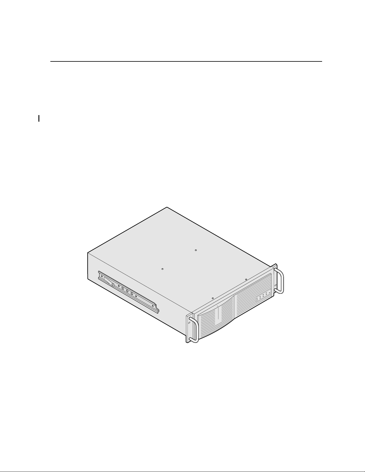
This is the Instruction Manual for the Grass Valley Group PDX218, Disk Expansion
Chassis (Figure 1-1). The manual con sists of:
• A description of the PDX218.
• Installation procedures.
• Maintenance procedures.
• Troubleshooting.
• Removal and replacement procedures.
9687-2
Figure 1-1. The PDX218 Disk Expansion Chassis
PDX218 Instruction Manual 1-1
Page 12

Chapter 1 Introduction
Related Documentation
Profile PDR200 & PDR300 Installation Manual
Profile Family User Manual
Profile Syst em Sof twa re Re le as e No te s
Organization of the Manual
This instruction manual consists of the chapters identified and described below.
Chapter 1 - Introduc tion: Thi s chapt er descr ibes the c ontents of the manual and the
PDX218 chassis. It i ncl udes ph ysical and ele ctric al spe cific ations and e nvironmen tal
criteria.
Chapter 2 - Installation: This chapter describes the physical installation of the
PDX 218 including initial power-on. It includes configuration information.
Chapter 3 - Service: This chapter consists of maintenance inform ation,
troubleshooting procedures, and removal and replacement procedures. The chapter
includes a list of Field Replaceable Units (FRUs) and pin-outs for the rear panel
SCSI-2 connector.
Product Description
The PDX218 Disk Expansion Chassis provides external stor age for the Pr ofile Video
File Server. The PDX 218 contains eight 18GB Ultra-SCSI disk drives on two SCSI
buses; four disk drives on each bus. The two SCSI buses can be connected togethe r,
using one of the external SCSI cables provided, placing all eight disk drives on a
single SCSI bus. This design provides the flexibility to operate the PDX218 with
different Profile Video File Server configurations.
The Profile Disk Utility, included with Profile system software, is used to configure
the PDX218 for operation as part of the Profile system. Fo r more information about
the Profile Disk Ut ili ty refer t o “Using the Pr ofile Dis k Uti lilt y” in the Profile Family
User Manual.
1-2 PDX218 Instruction Manual
Page 13
Storage Capac ity
The Profile Video File Server stor a ge capacity is determined by the number of disk
drives in the system and the select ed vid eo data rate used to record the video signal.
The Profile Video File Server stor age space can be expanded by adding one or two
PDX218 Disk Expansion Chassis containing eight 18GB disk drives each.
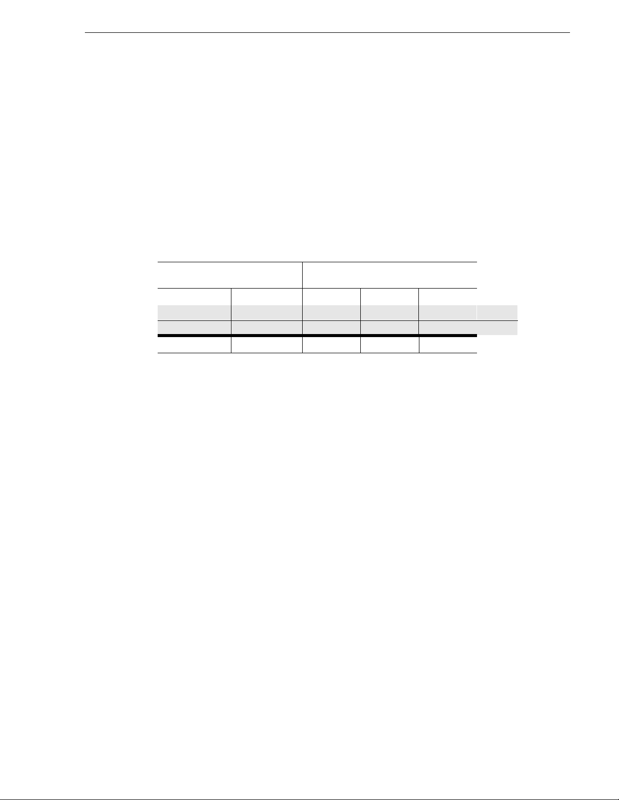
Table 1-1 shows storage capacity estimates at selected video data rates for a sin gle
PDX218 containing eight 18GB disk drives
All Profile applic ations software allows yo u to select the video da ta rate used to record
the video signal. For more information about setting the video data rate, refe r the
appropriate sections of the Profile Family User Manual.
Table 1-1. PDX218 Storage Capacity Estimates (Eight 18GB disk driv es)
Storage Capacity
PDR200
JPEG Data Rate
48Mb/s 24Mb/s 24Mb/s 18Mb/s 15Mb/s
100KB/fld 50KB/fld 100KB/frm 80KB/frm 70/KB/frm 525/50
120KB/fld 60KB/fld 120KB/frm 90KB/frm 80KB/frm 625/50
5.4 hrs 9.9 hrs 10.2 hrs 13 hrs 15 hrs
Storage estimates include 4 channel s of audio and 2 chann els of timecode. Adding 4
more channels of audio adds approximately 3Mb/s to the total data rate.
PDR300
MPEG2 Data Rate
PDX218 Instruction Manual 1-3
Page 14
Chapter 1 Introduction
Product Features
Features of the PDX218 are:
• Contains its own power supply and connection to source power.
• Mounts on rac k slides for installation in a standard equipment rack.
• Control interface and media transfers from and to the Profile system are through
SCSI-2 cables connected to the rear panel (see Chapter 2, Installation).
• Front panel indicators.
Indicators
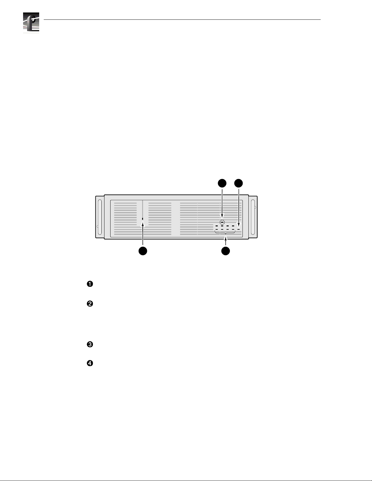
The following describe s the indicators on the PDX218 front panel (see Figure 1-2).
34
9687-17
1 2
Figure 1-2. PDX218 Indicators
Ê
Power indicator; gre en LED lighted when the power switch on the rear panel is
On.
Disk Activity indic ators; two bank s of four green LEDs show disk activity. Each
Ë
bank corresponds to a SCSI bus with four disk drives. Mapped to the physical
location of each h ard disk drive in the chassis, the LED s flash when act ivity
occurs on the associated disk. A LED that never fl as hes on or remains on may
indicate a problem with the associated disk.
System Fault indicator ; red LED off during normal ope ration. Lights to ind icate
Ì
either a terminal power failure or (with
Í
Fan Fault indi cator (behind the front panel bezel and only visible with the bezel
removed);
indicate
red LED off during normal operation . Lights (along with 3 above) to
a fan failure.
4 below lighted) a fan failure.
1-4 PDX218 Instruction Manual
Page 15

Specifications
The followin g tables list the electrical and physical specifications and environmental
criteria for the PDX218.
Definition of Terms Used in Tabl es
The following terms apply to the PDX218 as they appear in the following tables.
Specifications
Specification -
characteristics and performance requirements of equipment and certain program
material.
REQUIREMENT: (Performance Requirement)
characteristic usually in limit form.
SUPPLEMENTAL DATA: -
provide performance information. These are not considered to be statements of
guaranteed performance and are not ordinarily supported by a performance check
procedure.
A document or a section of a document that lists and describes
Electrical Specifications
Table 1-1 lists the el ect rical specificati on s for the PD X218.
Table 1-2. Power Source
Specifications Description
Electrical Rating Requirement: 100 -240V, 50/60 Hz, 3A maxim um
Supply Type Supplemental Data:Single Phase
Supply Connection Supplemental Data:Detachable cord set
Power C o nsumpt i o n Supplemen tal Data:<300 VA
- A statement that defines a
Statements that explain performance requirements or
PDX218 Instruction Manual 1-5
Page 16
Chapter 1 Introduction
Mechanical Specifications
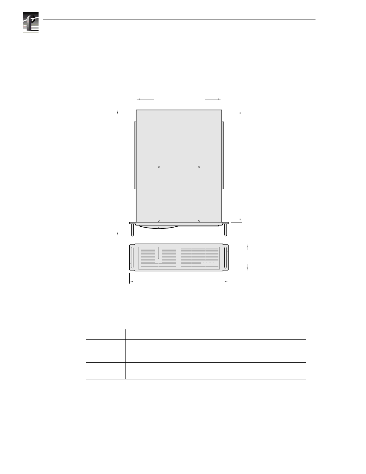
Figure 1-3 shows the dimensions of the PDX218 and Table 1-2 lists and the
mechanical specifications.
22.50 in
(57.25 cm)
16.87 in. (42.85 cm.)
20.25 in
(51.44 cm)
5.25 in
(13.34 cm)
19.00 in (48.26 cm)
Figure 1-3. Mechanical Specifications
Table 1-3. PDX218 Mechanical Specifications
Specification Description
Dimensions Requirement: Height: 5.250 inches (13.335 centimeters)
Width: 19.000 inches (48.260 centimeters)
Depth: 22.500 inches (57.150 centimeters)
Weight Requirement: Net: 51.5 pounds (23.360 kilograms)
Shipping:71 pounds (32.205 kilograms)
9687-1
1-6 PDX218 Instruction Manual
Page 17

Env ironmen tal Crite r ia
Environmental Criteria
Table 1-4. Environmental Criteria
Characteristics Description
Operating Tem perature Requirement: 10° to 40°C (+50° to 104°F)
Storage Temperature Requirement: -40° to 60°C (-40° to 140°F)
Operating Altitude Requirement: To 10,000 feet (3048 meters)
Supplemental Data:IEC 950 compliant to 2000 meters
Storage A ltitude Requirement: To 40,000 feet (12,192 meters)
Mechanical Shock Military Specification: Mil -T-28800D, Class 6 (Non-Operating Onl y)
Transportation Requirement: Qualified under NS TA Test Procedure 1A, Categ ory II (18 in ch drop)
Equipment Type Supplemental Data:Information Technology
Equipment Class Supplemental Data:Class I
Installation Category Requirement: Category II Local level mains, appliances, portable equipment
Pollution Degree Requirement: Level 2 operating environment, indoor use only
Humidity Requirement: Operating 8% - 90%
Non-Operating 8% - 90%
Maximum Wet Bulb Temperature 29° operating
Supplemental Data:Do not operate with visible moisture on the circuit boards
PDX218 Instruction Manual 1-7
Page 18

Chapter 1 Introduction
1-8 PDX218 Instruction Manual
Page 19

Chapter
2
Installing
This chapter describe s the physical installa tion of your PDX218 and configuring it for
use with your Profile Video File Serv er. The information includes:
• Mounting the PDX 218 in the equipment rack.
• Making PDX218 rear panel cable connections.
• Turning power On.
• Making a file system on the PDX218.
Rack Mounting
The PDX218 installs in a standard 19-inch equipment rack. Rack slides allow the
PDX218 to slide in and out without having to remove it from the rack. However, if
the rack does not already have rack slides installed, or if the slides are not correctly
positioned, you will have to use those shipped with the PDX218.
When determining the location of t he PDX218 in the rack, bear in mind that the unit
weighs approximately 51.5 pounds. Observe the following warnings:
WARNING: To prevent inju ry, t wo people a re req uired to li ft th e PDX218. It is too
!
heavy for one person to install in the rack.
WARNING: To prevent seriou s injury , in sure that the rack i s anc hored to the f loo r
!
so that it cannot tip over when the PDX218 is extended out of the rack.
PDX218 Instructi on Manual 2-1
Page 20
Chapter 2 Installing
Mounting the Slides in the Rack
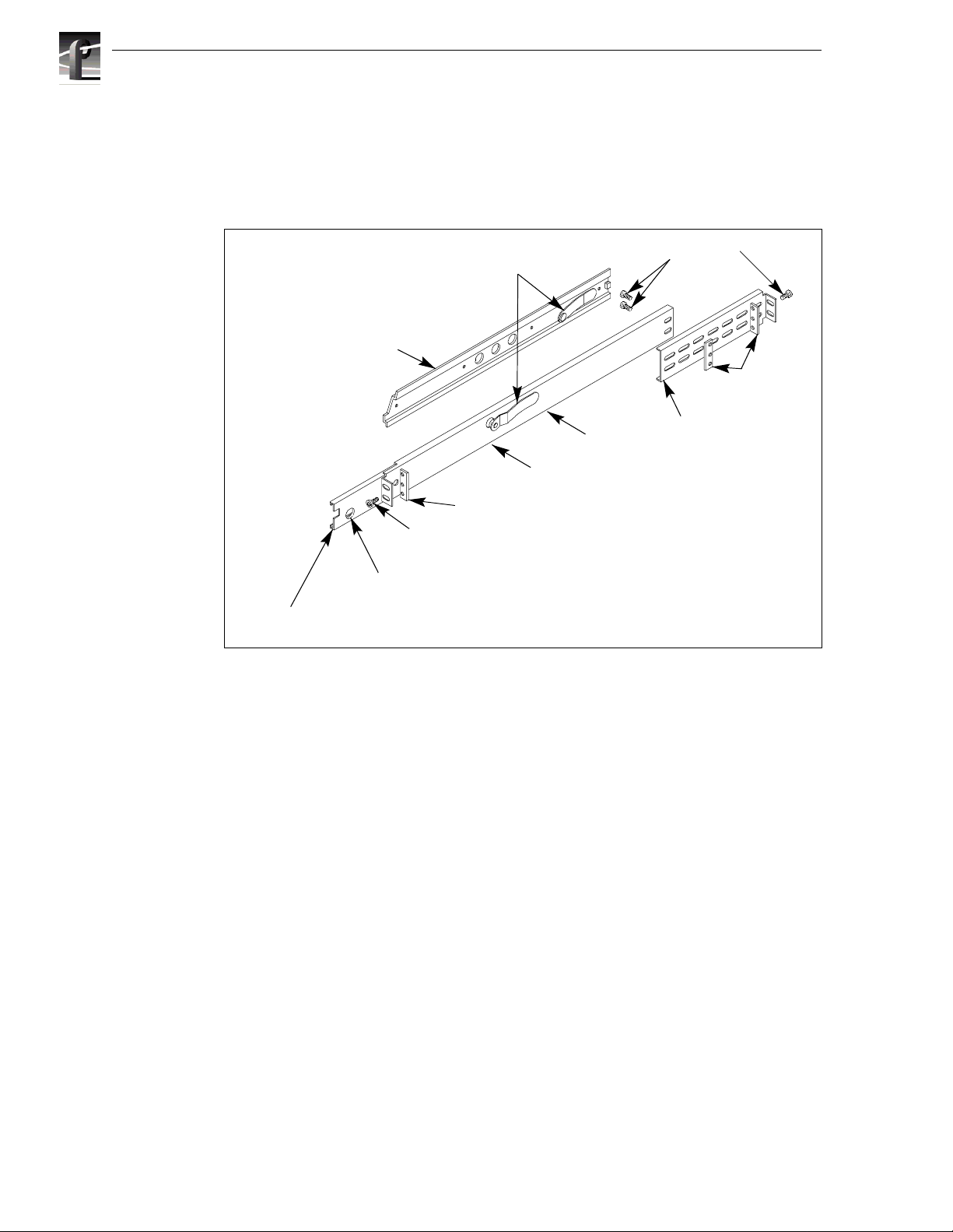
Figure 2-1 shows the components of a right-hand rack slide set. Note that the chassis
section is already atta ched to the PDX218. When mounting rack slides in the
equipment rack, bear in mind that the PDX218 occupies 3 RUs.
PDX 218 Ch assis Section
Stop Latch
Intermediate
Figure 2-1. Rack Slide Set for Right Side of Chassis and Rack
Automatic
Stationary
Rack
Flat Nut Bar
10-32 PHS
NOTE: Right-hand and left-hand stationary section is designated by the
RH and the LH marked on the rails. Stop latch holes should be towards
10-32 PHS
Rear
Flat
Nut
2-2 PDX218 Instruction Manual
Page 21

Mounting the Slides in the Rack
Locate the proper r ack holes as shown in F igure 2- 2. Notic e that the hole spa cing can
vary with the rack type. When mounting the slides in racks with EIA spacing, make
sure that the slides are attached to the 0.5-inch spaced holes.
MIL STD 189
1.250 in
0.625 in
1.250 in
Figure 2-2. Spacing for Mount ing Holes in a Rack
“UNIVERSAL” SPACING
1.250 in
0.625 in
0.500 in
PDX218 Instructi on Manual 2-3
Page 22

Chapter 2 Installing
Mount the slides u sing the enclos ed hardwar e as shown in Fi gure 2-2. Figur es 2-3 and
2-4 show the front and rear slide mounting de tails for both deep and shallow racks.
Make sure the stationary sections are horizontally aligned and are level as well as
parallel to each other.
BAR NUT
(Use if the front rail is not tapped)
Figure 2-3. Front Slide Mounting Det ail
BAR NUT
REAR RACK RAIL
Figure 2-4. Rear Slide Mount ing Detail
PNH
2-4 PDX218 Instruction Manual
Page 23

Mounti ng the PDX218
In addition to having room to make cable connections, the PDX218 requires six
inches (15.25 cm) of clearance behind the rear pa nel for connectors and cable bends.
Adequate air flow must also be assured around the chassis to provide sufficient
cooling. (Operating ambient temperature will affect the amount of air circ ulation
required to keep the PDX218 within its temperature limitations.)
1. Pull the slide-out section to the full y extende d position. See Figure 2-5.
WARNING: To prevent injury, two people are required to lif t the PDX218. The
!
PDX218 is too heavy for one person to install in the rack.
WARNING: To prevent seriou s injury , in sure that the rack i s anc hored to the f loo r
!
so that it cannot tip over when the PDX218 is extended out of the rack.
2. Insert the ends of the chassis sections into the slide-out sections.
3. Push the chassis toward the rack until the chas sis sections lock int o the intermediate
sections.
4. Press the stop latches in the intermediate sections and push the chassis toward the
rack until the latches sna p into their holes.
Mounting the PDX218
5. Again, press the stop latches and push the cabinet fu lly into the rack.
6. Insert and tighten the front panel retaining screws.
Rack Slide Adjustm ents
After instal lation, binding may oc cur if the sl ides a re not p rop erly adj usted. To adjus t
the slides:
1. Slide the chassis out approximately 10 inches.
2. Slightly loosen t he mounting screws holding the slides to the front of the rack and
allow the slides to seek an unbound posit ion.
3. Tighten the mounting screws and check the slides for smooth operation by sliding
the chassis in and out of the rack several times.
4. Tighten the front panel re taining screws once the cabinet is in plac e within the rack
to complete the installation.
Stop Latch
Figure 2-5. Rack Slide Stop Latc h
PDX218 Instructi on Manual 2-5
Page 24

Chapter 2 Installing
Making Cable Connections
All cables connect to the PDX218 SCSI Bus 1 and SCSI Bus 2 connectors on the rear
panel as shown in Figure 2-6.
SCSI Bus 1
connectors
Figure 2-6. PDX218 SCSI Bus Connectors
SCSI Bus 2
connectors
9687-18
PDX218 SCSI Cable Connections
The following examples show SCSI cabl e connections bet ween the PDX218 and the
Profile Video File Server.
NOTE: After making SCSI connections, you must use the Profile Disk Utility
software to create a file system on the PDX218 disk drives before i t can operate as
part of the Profile system. See “Creating a File System on the PDX218” on page
2-12.
One PDX 2 18 Connected to a Profile System with Two Disk Recorder Boards
Figure 2-7 shows a PDX218 connected to a Profile system with Master an d Slave
Disk Recorder Boards installed. The location of the Disk Recorder Boards may be
different than shown in Figur e 2-7. To loc ate the Disk Recorder boards in your
system, see the rear panel board slot labels.
Disk
Recorder
Slave
Figure 2-7. Connecting the PDX218 to a Profile System with Two Disk Recorder Boards
Disk
Recorder
Master
Profile Video
File Server
Note:
Disk recorder board locations may be
different than shown. See rear panel
labels for actual locations.
PDX218
SCSI Cable
Terminator
9687-26
2-6 PDX218 Instruction Manual
Page 25

PDX218 SCSI Cable Connections
To make SCSI cable connections refer to Figure 2-7 and:
1. Connect a SCSI cable from the PDX218 SCSI Bus 2 connector to the Profile
system rear panel connector in the slot labeled DISK RECORDER Master.
2. Connect a SCSI cable from the PDX218 SCSI Bus 1 connector to the Profile
system rear panel connector in the slot labeled DISK RECORDER Slave.
3. Connect SCSI Terminators to the unused SCSI Bus 1 and SCSI Bus 2 connectors
on the PDX218.
The PDX218 connections shown in Fi gure 2-7 provide four 18GB disk drives to the
SCSI A bus and four 18GB disk drives to the SCSI C bus on the Profile system (or
SCSI A & B bus on a PDR100).
PDX218 Instructi on Manual 2-7
Page 26

Chapter 2 Installing
One PDX218 Con ne cted to a Profi l e System wi th One Disk Recorder B o ar d
Figure 2-8 shows a PDX218 connected to a Profile system with only a Master Disk
Recorder board ins t all ed . Th e loca tio n of the Mast er D isk Recorder board ma y be
different tha n shown in Fi gure 2- 8. To loc ate the Mas ter Disk R ecorde r boar d in your
system, see the rear panel board slot labels.
To connect a PDX218, refer to Figure 2-6 and Figure 2-8 and:
1. Connect a SCSI cable from the PDX218 SCSI Bus 2 connector to the Profile
system rear panel connector in the slot labeled DISK RECORDER Master.
2. Connect a SCSI cable between SCSI Bus 1 and SCSI Bus 2 on the PDX218.
3. Connect a Terminator to the unused SCSI Bus 1 connector on the PDX218.
Disk Recorder Master
Profile Video
File Server
Note:
Disk recorder board location may be
different than shown. See rear panel
labels for actual location.
PDX218
SCSI Cable
Terminator
9687-27
Figure 2-8. Connecting the PDX218 to a Profile System with a Master Disk Recorder Board
The connection shown in Figure 2-8 provide s eight 18GB disk drives to the Profile
system SCSI A bus.
2-8 PDX218 Instruction Manual
Page 27

PDX218 SCSI Cable Connections
Two PDX218s Connected to a Profile System with Two Disk Recorder Boards
Figure 2-9 shows a PDX218 connected to a Profile system with Master an d Slave
Disk Recorder boards installed. The location of the Disk Recorder boards may be
different than shown in Figur e 2-9. To loc ate the Disk Recorder boards in your
system, see the rear panel board slot labels.
To connect two PDX 218s, refer to Figure 2-6 and Figure 2-9 and:
1. Connect a SCSI cable from t he first PDX218 SCSI Bus 2 connector to the Profile
system rear panel connector in the slot labeled DISK RECORDER Master.
2. Connect a SCSI cable between the SCSI Bus 1 and SCSI Bus 2 connectors on the
first PDX218.
3. Connect a Terminator to the unused SCSI Bus 1 connector on the first PDX218.
4. Connect a SCSI cable from the second PDX 218 SCSI Bus 1 connector to the
Profile system rear panel connector in the slot labeled DISK RECORDER Slave.
5. Connect a SCSI cable between the SCS I Bus 1 and SCSI Bus 2 connectors on the
second PDX218.
6. Connect a Terminator to t he unus ed SCSI B us 2 connec tor on the s econd PDX218.
Disk
Recorder
Slave
Figure 2-9. Connecting Two PDX218s to a Profile System with Master and Sla ve Disk Recorder Boards
Disk
Recorder
Master
Profile Video
File Server
Note:
Disk recorder board locations may be
different than shown. See rear panel
labels for actual locations.
First PDX218
Second PDX218
SCSI Cable
Terminator
9687-24
The connection shown in Figure 2-9 provide s eight 18GB disk drives to the SCSI A
bus and eight 18GB disk drives to the SCSI C bus on the Profile system (or SCSI A
and SCSI B bus on the PDR100).
PDX218 Instructi on Manual 2-9
Page 28

Chapter 2 Installing
Power Conne ctions
Power Sou r ce
The PDX218 operates from a single-phase power source having one of its
current-carryi ng conductors a t or near earth ground (the neutra l conductor). A fuse on
the line conductor provides over-current protection. Grass Valley Group does not
recommend connection to systems whose power source has both current carrying
conductors live with res pect to ground, such as phase-to-phase in multi-phase
systems.
Source Power Frequency and Voltage Ranges
The PDX218 operates at line frequencies of 50 or 60 Hz at nominal voltages from 100
to 240 VAC. Table 2-1 lists the power cord shipped with the PDX 218. Figure 2-10
shows the location of the power cord connec tor and the power switch.
2-10 PD X218 Instruction Manual
Page 29

Table 2-1. Power Cords for the PDX218 Disk Expansion Chassis
Power Plug Description
Standard 120 V , 3-pr ong po wer plug on a 2.5 met er long
power cord. For use with common ground systems in
North America.
Option A1 Un iversal European 2 30V/10A p ower pl ug on
a 2.5 meter long power cord.
Power Connections
Option A2
2.5 meter long power cord.
Option A3 Australian 230V/10A power plug on a 2. 5
meter lo ng power co rd .
United Kin gdom 230V/10A powe r plug on a
Insure that the power switch i s set to 0 (Off). Att ach the powe r cord from the PDX218
to the appropriate power s ource.
Power Cord
connector
Figure 2-10. PDX 218 Power Cord Connector and Switch
Power
switch
9687-6
PDX218 Instructi on Manual 2-11
Page 30

Chapter 2 Installing
Creating a File System on the PDX218
Now that the PDX218 is connected to the Profile system, you must use the Profile
Disk Utility to conf igure the disk driv es to stor e media by cre ating a file syste m (also
called making a data set in t he Profi le Disk Util ity). Refe r to the Profile Family User
Manual, “Using the Profile Disk Utility”, for detailed inf ormation about creating a file
system on the PDX218 disk drives. In addition, c onsider the following when crea ting
file systems with the Profile Disk Utility:
• When one PDX218 chassis is connected to a Profile system, the disk drives can be
grouped in the following ways:
- You can create a you a single file system including all externa l disk drives and
internal disk drives ( if installed).
- You can create a single ex tern al file syst em whi ch includes all eigh t extern a l
disk drives and a single interna l file system which includes all inte rnal drives (if
installed).
• When two PDX 218 chassis are connected to a Profile system, the disk drives can
be grouped the following ways:
- You can create a single file s ystem including al l exter na l di sk dri ve s and al l
internal disk drives ( if installed).
- You can create a single external file system which includes all sixteen external
disk drives. If internal disk drives are installe d, you c an create a single internal
file system.
- You can create two external file syste ms, eight disk driv es each. Each eight disk
file system include s four disks from both PDX218 chassis. If internal disk dr ives
are installed, you can also cre ate a single internal file system.
• If you are connecting the PDX218 to a Profile system with internal disk drives
smaller than 18GB, you may want to create two file systems. When creating a file
system, the Profile system limits the usable disk space of the larger drives to the
size of the sma llest drives in the file s ystem. For exampl e, if you are connecting the
PDX218 to a PDR100 with 4 GB disks, configure the PDX218 as a separate file
system. Making one file system including the internal 4GB drives and the external
18GB drives, limits the PDX218 storage capacity because the Profile system
recognizes the drive s in the PDX218 chassis as only 4GB drives.
• Some thir d party control software does not recognize internal and external file
systems. In this case, you must create one file system which includes all internal
and external disk drives.
• Oper ating the PDX218 with the Profile Video File Server requires Profile system
software 2.2.X greater than 2.2.4, 2.4.X greater than 2.4.4, or 2.5.X and greater.
2-12 PD X218 Instruction Manual
Page 31

WARNING
THE FOLLOWING SERVICING INSTRUCTIONS
ARE FOR USE BY QUALIFIED PERSONNEL
ONLY. TO AVOID PERSONAL INJURY, DO NOT
PERFORM ANY SERVICING OTHER THAN THAT
CONTAINED IN OPERATING INSTRUCTIONS
UNLESS YOU ARE QUALIFIED TO DO SO.
REFER TO OPERATOR’S SAFETY SUMMARY
AND SERVICE SAFETY SUMMARY PRIOR TO
PERFORMING ANY SERVICE.
Page 32

Page 33

Service Safety Summary
Service Safety Summary
Review the following safet y prec autions to avoid injury and prevent
damage to this product or any products connected to it.
Only qualified personne l should perform service procedures.
While using this product, you may need to access other parts of the
system. Read the General Safety summary in other system manuals for
warnings and cautions related to operating the system.
Safety Terms and Symbols
Terms in This
Manual
!
!
Terms on the
Product
!
!
Symbols on the
Product
These terms may appear in this manual:
WARNING: Warning st atements identify con ditions or practi ces that can
result in personal injur y or loss of life.
CAUTION: Caution statements identify conditions or practices that can
result in damage to the equipment or other property.
These terms may appear on the product:
DANGER indicates a personal injury ha zard immediately accessible as
one reads the marking.
WARNING indicates a personal injur y hazard not immediately
accessible as you read the marking.
CAUTION indicates a hazard to property inc luding the product.
The following symbols may appear on the produc t:
DANGER high voltage
Protective ground (ear th) terminal
!
ATTENTION – refer to manual
PDX218 Instruction Manual
Page 34

PDX218 Instruction Manual
Page 35

Chapter
3
Service
This chapter co ns ists of:
• Maintenance information.
• Troubleshooting procedures.
• Removal and replacement procedures for Field Replaceable Units (FRUs).
• Replaceable Parts Li st
• SCSI connector pin-outs
PDX218 Instruction Manual 3-1
Page 36

Chapter 3 Service
Maintenance
There is no specifically require d periodic maintenance for the PDX218. Cleaning the
exterior is on an “as needed” basis. Checking and cleaning or replacing the air filter
will depend on the operating envir onment. Procedures for doing these tasks are
discussed below.
WARNING: To avoid damage to the unit, if a liquid of any kind is spilled onto the
!
PDX218, immediately turn power Off and insure that both the inside and the
outside are completely dry before re-applying power.
Cleaning
Clean the PDX218 often enough to prevent dust or dirt from acc umulating. Dirt acts
as a thermal insulating bla nket that prevents effective heat dissipation, and can
provide high-resi stance electrical l eakage paths between conduc tors or components in
a humid environment.
Exterior
Clean the dust from the outside by wipi ng with a sof t cloth or small brush . A brush is
especially usefu l to remove dust from around the connectors. Hardened dirt may be
removed with a cl oth dampened i n wa ter or a 50 % isopropyl al cohol sol ution . Do not
use an abrasive cl ea ne r.
Interior
!
Clean the inter ior by lo osening a ccumulate d dust with a dry, soft br ush. Onc e the dir t
is loosened, remove it with low-pre ssure air (high-velocity air can damage some
parts). Remove hardene d dirt or grease wit h a cotton-tipped applica tor dampened with
a solution of mild detergent and water. Do not use an abrasive cleaner. If the circuit
board assembly must be removed for cleaning, follow the removal/replacement
instructions.
After cleaning, a llow the int erio r to thor oughly dry bef ore appl ying power to the unit .
CAUTION: Do not allow w ater to get inside any enclosed assembly or component.
Do not clean any plastic material s with organic cleanin g solvents, such as benze ne,
toluene, xylene, aceton e, or similar compounds, because they may damage the
plastic.
3-2 PDX218 Instruction Manual
Page 37

Cleaning and Changing the Air Filter
In a humid environment, the air filt er behind the front bezel of the PDX218 will
usually requir e more fre quent attent ion than in a dryer environment. F igure 3-1 sh ows
the location of the filter which requires removal of the front bezel. To remove the air
filter for cleaning or replacement, refer to Figure 3-1, and proceed as follows:
Cleaning and Changing the Air Filter
Unsnap Front
1
Panel Bezel
Air Filter
Remove
Air Filter
Air Filter
2
9687-8
Figure 3-1. PDX218 Air Filter Removal
1. Unsnap the front panel bezel by firmly pulling away from the front panel.
2. Detach the air filter from the studs behind the bezel.
3. If cleaning, use a low pressure air supply to blow contamina nts out of the filter.
4. Attach the filter to the bezel as shown in Figure 3-1.
5. Position the front panel bezel mounting posts over the holes in the front panel and
snap the bezel back in place.
PDX218 Instruction Manual 3-3
Page 38

Chapter 3 Service
Troubleshooting
If you suspect that the PDX218 is the cause of a Profile-related problem:
• Check al l SCSI cable connections.
• Check the power cord connection.
• Insure the On/Off switch is O n .
• Insure that the power switch and line filter are good.
• Check the indicators on t he front panel (Figure 3-2) which provide information to
assist in fault isola tion.
If it is necessa ry to re place a co mponent, se e Removal an d Replacement Procedures
later in this chapter.
Refer to Figure 3-2 in the following disc ussions.
Power On LED Disk activity
Figure 3-2. PDX 218 Front Panel Indicators
Power On Indicator
The chassis power green LED indicator should be On.
If Off
- Powe r Supply bad , repla ce Power Supply.
- Fuse F1 or F3 on SCSI Distribution board blown, replace SCSI Distribution
board.
- LED cable assembly bad, replace cable assembly.
Fan failure LED
(located behind bezel)
System fault
LED
9687-7
LEDs
3-4 PDX218 Instruction Manual
Page 39

Disk Activity Indicators
These eight green LED indicators show Disk Ac tivity.
If one or more LED(s) is frozen On or Off.
- Profile system crash, see Profile Family User Manual or Profile Service Manual.
- One or more bad disk drives. One bad disk drive will, after a few seconds, cause
all the Disk Activity LEDs to freeze On or Off. Turn PDX218 power off, then,
while observing these LEDs, turn power back on. The bad disk drive will not
show activity, replace that drive.
- SCSI Distribution boa rd bad, rep l ace.
- An external or internal cable is loose or bad. Check all cables, rec onnect or
replace as necessary.
All Disk Activity LEDs go off, but PDX218 remains operative.
- Fuse F3 on SCSI Distribution board blown, replace SCSI Distribution board.
Disk Activity LEDs do not flash.
- LED Board bad, repl ace LED Bo ar d.
- Disk Drive LEDs cable bad, replace.
Disk Activity Indicators
System Fault Indicator
The System Fault red LED indicator may be On under the two conditi ons listed
below. Remove the front bezel to determine which condition is present.
1. System Fault LED On but
terminal power fuses on the SCSI Distribution board has blown, replace SCSI
Distribution board.
2. System Fault LED On and
fans is bad. Turn PDX218 power Off, remove the top cover (see Removal and
Replacement Procedures) , br iefly turn power back On. Replace whichever fan is
not turning.
Fan Faul t In d ica to r
The Fan fault r ed LED indica tor is be hind the fr ont panel be zel. See above descripti on
on System Indicator.
Fan Fault indicator LED Off, one (or more) of the
the Fan Fault indicator LED On, one (or more) of the
PDX218 Instruction Manual 3-5
Page 40

Chapter 3 Service
Removal and Replacement Procedures
This section identifies the replaceable parts of the PDX218 and the procedures to
remove and replace them.
NOTE: Do not discard any hardware unless specific ally instructed to do so.
WARNING: To avoid electric shock, insure that the power cord is disconnected
!
prior to performing any removal and replac ement procedure.
Replaceable Parts
Table 3-1 lists the PDX218 replaceable parts. Figure 3-3, keyed to Table 3-1, shows
the parts.
Table 3-1. PDX 218 Replaceable Part List
Key Part Number Description
1 119-5195-XX Power Supply
2 119-4827-XX Fan, DC
3 671-4120-XX SCSI Distribution Board, Single Ended
4 119-6086-XX Video Disk Drive, 18GB, Single Ended
5 407-4478-XX Disk Drive Caddie
6 174-3748-XX Cable, Power Supply to SCSI Distribution Board
7 174-3612-XX Cable, Line In to Power Supply
8 174-3586-XX Cable, Line In/Switch to Power Supply
9 174-3668-XX Cable, SCSI Internal/External
10 174-3751-XX Cable, Disk Drive to LED
11 671-3948-XX LED Board Assy, PDX 218
12 174-3616-XX Cable Assy, LED
13 378-0432-XX Air Filter
14 333-4222-XX Front Bezel
15 200-4295-XX Front Plastic Ear
16 367-0450-XX Handle, Front Chassis
17 174-3517-XX
174-4181-XX
174-4182-XX
18 011-0166-XX Terminator, SCSI
Cable, External SCSI, Stan dard Profile system to PDX218, 73 inch
Cable, External SCSI, Prof ile system to PDX218, 3 foot
Cable, External SCSI, Prof ile system to PDX218, 10 foot
3-6 PDX218 Instruction Manual
Page 41

Replaceable Parts
1
2
6
3
4
7
8
9
5
18
17
15
16
Figure 3-3. Replaceable Parts
10
12
9687-25
11
13
14
PDX218 Instruction Manual 3-7
Page 42

Chapter 3 Service
Removi ng and Repla cing the Front Panel Bezel and Air Filter
For front panel bez el and air filter removal/replace ment, see Cleaning an d Changing
the Air Filter previously discussed in this chapter.
Removing and Replacing a Disk Drive
A disk drive caddie holds each disk drive in place (items 4 and 5 in Table 3-1). If in
troubleshooti ng the PDX218, a disk drive is determined to be bad, the hinged front
panel must be loosened and lowered, and the appropriate caddie must be removed
before the disk drive can be removed and replaced. It is not necessary to remove the
PDX218 from the rack to perform this procedure. See Figure 3- 4 to lower the front
panel and Figure 3-5 to remove the caddie and disk drive.
Remove screws (14)
1
Open hinged
2
front panel
3-8 PDX218 Instruction Manual
9687-12
Figure 3-4. Lowering the Front Panel
Page 43

Removing and Replacing a Disk Drive
Slide drive out
1
Remove drive
2
from bracket
9687-10
Figure 3-5. PDX218 Disk Drive Caddie and Disk Drive Removal
To remove a caddie and disk drive:
1. Unsnap the front panel bezel by firmly pulling away from the front panel (Figure
3-1).
2. Remove the retaining screws from the front panel. (Figure 3-4) (These are also
caddie retaining screws.)
3. Lo wer the front panel.
4. Grasp the appropriate caddie, pull straight out of the chassis, a nd place on a level,
static-proof sur face (Figure 3-5).
5. Remove the drive mounting screws and remove the drive from the caddie.
To install a disk drive and reinsta ll a caddie:
1. Mount the new drive in the caddie using the screws previously removed from the
caddie (Figure 3-5).
2. Sli de the cad d ie int o the ch as si s.
3. Raise the front panel and secure it with the screws previously removed (Figure
3-4).
4. Position the front panel bezel mounting posts over the holes in the front panel and
press firmly until the bezel sna ps ba ck in place (Figure 3-1).
PDX218 Instruction Manual 3-9
Page 44

Chapter 3 Service
Removing and Replacing the LED Board
The LED Board (item 11 in Table 3-1) is on the front panel It is not necessary to
remove the PDX218 from the rack to perform this procedure. Figure 3-6 shows
removal of the LED board.
Unsnap LED Board from
1
the two mounting posts
Pull LED out of
front panel socket
Figure 3-6. PDX 218 LED Board and Cable Removal
9687-11
Unplug cabling and
3
remove LED board
3-10 PD X218 Instruction Manual
Page 45

Removing and Replacing the LED Cable Assembly
To remove LED board:
1. Unsnap the front panel bezel by firmly pulling away from the front panel (Figure
3-1).
2. Remove the retaining screws from the front panel. (Figure 3-4) (These are also
caddie retaining screws.)
3. Lo wer the front panel.
4. Unsnap the LED board fr om the mounting posts (Figure 3-6) by pulling the board
straight up from the front panel.
5. Disconnect the cables from the LED board.
To install the LED board:
1. Connect the previously removed cables to the LED board.
2. Position the LED board over the mounting post s in the front panel and firml y press
down until the LED board snaps into place (Figure 3-6).
3. Raise the front panel and se cure with the screws previously r emoved (Figure 3-4).
4. Position the front panel bezel mounting posts over the holes in the front panel and
press firmly until the bezel sna ps ba ck in place (Figure 3-1).
Removing and Replacing the LED Cable Assembly
This cable assembly (ite m 12 in Table 3-1) conne cts from the LED board to the front
panel power LED. It is not nec essary to remove the PDX218 from the rack to perform
this procedure. Figure 3-6 shows removal of the LED cable assembly. To remove
LED cable assembly:
1. Unsnap the front panel bezel by firmly pulling away from the front panel (Figure
3-1).
2. Remove the retaining screws from the front panel. (Figure 3-4) (These are also
caddie retaining screws.)
3. Lo wer the front panel.
4. Unsnap the LED board fr om the mounting posts (Figure 3-6) by pulling the board
straight up from the front panel.
5. Disconnect the LED cable assembly from the LED board (Figure 3-6).
6. Pull the LED end of the cable out of the front panel socket.
To install the LED board:
1. Connect the new LED cable assembly to the LED board (Figure 3-6).
2. Position the LED board over the mounting post s in the front panel and firml y press
down until the LED board snaps into place (Figure 3-6).
3. Ins ert the L E D end o f the cabl e i nto the fro nt pa nel so ck et.
4. Raise the front panel and se cure with the screws previously r emoved (Figure 3-4).
5. Position the front panel bezel mounting posts over the holes in the front panel and
press firmly until the bezel sna ps ba ck in place (Figure 3-1).
PDX218 Instruction Manual 3-11
Page 46

Chapter 3 Service
Removing and Replacing the Disk Drive LEDs Cable
This cable (item 10 in Table 3-1), for the dis k dri ve activi ty LEDs, conn ects from th e
LED board on the front panel to the SCSI Distribution board. It is not necessary to
remove the PDX218 from the rack to perform this procedure. Figure 3-7 shows the
LED board and cables.
Unplug cable
connectors and
2
remove cable
Remove
LED board
9687-19
Figure 3-7. Disk Drive LEDs Cabl e Remova l
1
To remove the Disk Drive LEDs cable:
1. Unsnap the front panel bezel by firmly pulling away from the front panel (Figure
3-1).
2. Remove the retaining screws from the front panel (Figure 3-4). (These are also
caddie retaining screws.)
3. Lo wer the front panel.
4. Unsnap the LED board fr om the mounting posts (Figure 3-6) by pulling the board
straight up from the front panel.
5. Disconnect the Disk Drive LEDs cable from the LED board (Figure 3-7).
6. Remove as many caddies as necessary to reach the Disk Drive LEDs cable where
it connects to the SCSI Distribution board (Figure 3-7). (See Removing a Disk
Drive.)
7. Disconnect the Disk Drive LEDs cable from the SCSI Distribu tion board.
3-12 PD X218 Instruction Manual
Page 47

To install a new Disk Drive LEDs cable:
1. Connect the new Disk Drive LEDs cable from the LED board to the SCSI
Distribution board ( Figure 3-7).
2. Replace the caddies previously removed.
3. Position the LED bo ard over the mounting posts on the f ront panel and firmly press
down until the board snaps into place (Figure 3-6).
4. Raise the front panel and se cure with the screws previously r emoved (Figure 3-4).
5. Position the front panel bezel mounting posts over the holes in the front panel and
press firmly until the bezel sna ps ba ck in place (Figure 3-1).
Removi ng the Top Cover
Figure 3-8 shows removal of the top cover, which must be removed to access the
interior for removal of other parts. To remove the top cover, refer to Figure 3-8 and:
1. Remove the PDX218 from the equipment rack.
2. Remove the cover mounting screws.
3. Lift the cover up and off the chassis.
Removing the Top Cover
9687-9
Figure 3-8. PDX218 Top Cover Removal
PDX218 Instruction Manual 3-13
Page 48

Chapter 3 Service
Removing the Disk Tray Cover
Figure 3-9 shows removal of the disk tray cover, which must be removed to gain
access for removal of other parts.
To remove the disk tray cover:
1. Remove the PDX218 from the equipment rack.
2. Remove the top cover (Figure 3-8).
3. Unsnap the front panel bezel (Figure 3-1).
4. Remove the front panel retaining screws and lower the front panel (Figure 3-4).
5. Remove all disk drive caddies (Figure 3-5).
6. Remove the screws and L-brackets, one on each side (Figure 3-9).
7. Remove the Disk Tray cover mounting screws.
8. Slide the Disk Tray cover out through the front of the chassis.
To install the disk tray cover:
1. Slide the Disk Tray cover in through the front of the chassis and secure with the
screws previously removed (Figure 3-9).
2. Install the L-brackets with the screws previously removed.
3. Install all disk drive caddies (Figure 3-5) previously removed.
4. Raise the front panel and se cure with the screws previously r emoved (Figure 3-4).
5. Position the front panel bezel mounting posts over the holes in the front panel and
press firmly until the bezel sna ps ba ck in place (Figure 3-1).
6. Replace the top cover (Figure 3-8).
7. Reinstall the PDX218 into the equipment rack.
3-14 PD X218 Instruction Manual
Page 49

Removing the Disk Tray Cover
Remove L-brackets
1
and screws as shown
9687-14
Figure 3-9. PDX218 Disk Tray Cover Removal
Slide forward
2
to remove
2
PDX218 Instruction Manual 3-15
Page 50

Chapter 3 Service
Removing and Replacing a SCSI Cable
Internal SCSI cables (item 9 in Table 3-1) connec t from two connectors on each side
of the SCSI Di stribution b oard to t he two rear panel SCSI conne ctors on the same side
of the chassis. Figure 3-10 shows removal of an internal SCSI cable.
1
Unplug connectors on
1
both ends of SCSI cables
and remove cables
9687-20
Figure 3-10. Removal of a SCSI Cable
3-16 PD X218 Instruction Manual
Page 51

Removing and Replacing a SCSI Cable
To remove an int ernal SCSI cable:
1. Remove the PDX218 from the equipment rack.
2. Remove the top cover (Figure 3-8).
3. Remove the Disk Tray cover (Figure 3-9).
4. If necessary, remove disk caddie(s).
5. Disconnect the bad SCSI cable connector from the SCSI Distr ibution board (Fi gure
3-10).
6. Disconnect the connector at the other end of the bad SCSI cable from the rear
panel.
To install a SCSI cable:
1. Connect the SCSI cable from the appropriate rear panel co nnector to the
appropriate SCSI connector on the SCSI Distribution board (Figure 3-10).
2. Install any disk caddies previous ly remov ed.
3. Install the Disk Tray cover (Figure 3-9) .
4. Replace the top cover (Figure 3-8).
5. Reinstall the PDX218 into the equipment rack.
PDX218 Instruction Manual 3-17
Page 52

Chapter 3 Service
Removing and Replacing the SCSI Distribution Board Power Cable
Figure 3-11 shows removal of the cab le that provides power from the Power Supply
to the SCSI Distribution boar d (item 6 in Table 3-1).
Remove three
nuts and remove
1
air baffle
Unplug
2
power cable
Black
(two wires)
Red
(two wires)
Black
Yellow w/red stripe
Black w/yellow stripe
Yellow
Yellow
Black w/yellow stripe
3
Figure 3-11. Removal of the SCSI Distribution Board Power Cable
(two wires)
Remove power cable
wires from power supply
9687-21
(two wires)
3-18 PD X218 Instruction Manual
Page 53

Removing and Replacing the SCSI Distribution
To remove the SCSI Distribution boar d power cable:
1. Remove the PDX218 from the equipment rack.
2. Remove the top cover (Figure 3-8).
3. Remove the Disk Tray cover (Figure 3-9).
4. Remove as many caddies as necessary to access the Power Suppl y connector on the
left side of the SCSI Distribut ion board (Figure 3-5).
5. Disconnect the Power Supp ly connect or from the SCSI Dis tributi on boar d (Fig ure
3-11).
6. Remove the air baffle.
7. Disconnect the SCSI Distribution boa rd power cable wires from the Power Supply.
To install the SCSI Distribution board power cable:
1. Connect the cable wires to t he left s ide (as f aci ng the chas sis) of the Power Su pply
(see the insert in Figure 3-11).
2. Connect the Power Supply cable connector to the SCSI Distribution board.
3. Reinstall the air baffle.
4. Install the Disk Tray cover (Figure 3-9) .
5. Replace the top cover (Figure 3-8).
6. Reinstall the PDX218 into the equipment rack.
PDX218 Instruction Manual 3-19
Page 54

Chapter 3 Service
Removing and Replacing the Switch Cable
Figure 3-12 shows re moval of the cable assembly that connects the Power Supply to
the rear panel switch (item 8 in Table 3-1). This assembly includes the switch.
1
Remove
shield
Press tabs on top &
3
bottom of power switch
to remove through
rear panel
Remove wires
2
from power
supply
Press tabs on sides of
power cord connector
to remove through
rear panel
Unplug
wires(2)
Remove
ground
wire
Figure 3-12. Removal of the Switch and Line In Cables
3-20 PD X218 Instruction Manual
9687-22
Page 55

Removing and Replacing the Line In Cable
To remove the Switch cable:
1. Remove the PDX218 from the equipment rack.
2. Remove the top cover (Figure 3-9).
3. Remove the shield (Figure 3-12).
4. Disconnect the blac k and white c able wires f rom the r ight side o f the Power Supply
(Figure 3-12).
5. Disconnect the switch cable wires from the power connector.
6. Compress the retaining clips on the top and bottom of the switch and remove the
switch out of the chassis through the rear panel.
To install the Switch cable:
1. Install the switch into the chassis thr ough the rear panel with 0 (Off) at the bottom.
2. Connect the switch cable wires to the right side of the Power Supply as shown in
the insert in Figure 3-12.
3. Connect the switch cables wires to the power connector as shown in the insert in
Figure 3-12.
4. Replace the shield.
5. Replace the top cover (Figure 3-8) and reinstall the PDX218 into the rack.
Removing and Replacing the Line In Cable
Figure 3-12 shows the cable assembly tha t con nects the switch to the power cord
connector (item 7 in Table 3-1). This assembly includes the source power conne ctor
and line filter. To remove the pow er con n ecto r cab le as semb l y:
1. Remove the PDX218 from the equipment rack.
2. Remove the top cover (Figure 3-8).
3. Remove the shield (Figure 3-12).
4. Disconnect the power connector wires from the switch assembly (Figure 3-12).
5. Remove the chassis ground wire retaining nut.
6. Compress the retaining clips on each side of the power connector assembly and
remove the connector out of the chassis through the rear panel.
To install the Line In cable assembly:
1. Install the Line In asse mbly in to t he chass is t hrough t he rea r pane l wit h the g round
contact of the connector to the near side of the chassis.
2. Connect the power connector cable wires to the switch assembly as shown in the
insert in Figure 3-12.
3. Attach the chassis ground wire as shown in Figure 3-12.
4. Replace the shield (Figure 3-12).
5. Replace the top cover (Figure 3-8) and reinstall the PDX218 into the rack.
PDX218 Instruction Manual 3-21
Page 56

Chapter 3 Service
Removing and Replacing the Power Supply
Figure 3-13 shows removal of the Power Supply (ite m 1 in Table 3-1).
Remove four screws from
rear panel and remove
power supply.
4
Remove three
nuts and remove
1
air baffle
Remove shield and
3
detach two wires
Black
(two wires)
Red
(two wires)
Black
Yellow w/red stripe
Black w/yellow stripe
Yellow
Yellow
Black w/yellow stripe
2
Figure 3-13. PDX218 Power Supply Removal
(two wires)
(two wires)
Remove power cable
wires from power supply
9687-16
3-22 PD X218 Instruction Manual
Page 57

Removing and Replacing the Power Supply
To remove the power supply:
1. Remove the PDX218 from the equipment rack.
2. Remove the top cover (Figure 3-8).
3. Remove the Disk Tray cover (Figure 3-9).
4. Remove the shield from the right side of the Power Supply (Figure 3-13)
5. Remove the mounting nuts from the air baffle and lift the baffle up and out of the
chassis (Figure 3-13).
6. Remove the Power Supply moun ting scre ws fr om the rea r pan el and lif t the Power
Supply up and out of the chassis jus t enough to access the cable wire connections
on each side of the Power Supply.
7. Disconnect the SCSI Distribution board cable wires from the left side of the Power
Supply (Figure 3-13).
8. Disconnect the black and white Switch c able wires f rom the rig ht side of the Power
Supply (Figure 3-13).
9. Lift the Power Supply completely free of the chassis.
To reinstall the power suppl y:
1. Connect the cable wires from the Switch to the right side of the Power Supply
(Figure 3-13).
2. Connect the SCSI Distribution board cable wires to the left side of the Power
Supply (Figure 3-13).
3. Position the Power Supply at the rear panel and mount wit h the screws previously
removed (Figure 3-13).
4. Replace the shield.
5. Replace the air baffle using the mounting nut s previously removed.
6. Replace the top cover (Figure 3-8).
7. Reinstall the PDX218 into the equipment rack.
PDX218 Instruction Manual 3-23
Page 58

Chapter 3 Service
Removin g and R ep lac in g a Fan
Figure 3-14 shows removal of a fan (item 2 in Table 3-1).
Remove four screws from
2
fan and remove fan as shown.
Unplug fan cable
1
from end of board
9687-15
Figure 3-14. PDX218 Fan Removal
3-24 PD X218 Instruction Manual
Page 59

Removing and Replacing a Fan
To remove a fan:
1. Remove the PDX218 from the rack.
2. Remove the top cover (Figure 3-8).
3. Remove the Disk Tray cover (Figure 3-9).
4. Disconnect the appropriate fan cable from the left or right side of the SCSI
Distribution board ( Figure 3-14).
5. Remove the appropriate fan mounting screws and lift the fan up and out of the
chassis.
To install a fan:
1. Position the fan and mount with the screws previously removed (Figure 3-14)
2. Connect the new fan cable to the left or right side of the SCSI Distribution board.
3. Reinstall the Disk Tray cover (Figure 3-9).
4. Replace the top cover (Figure 3-8).
5. Reinstall the PDX218 into the Equipment rack.
PDX218 Instruction Manual 3-25
Page 60

Chapter 3 Service
Removing and Replacing the SCSI Distribution Board
Figure 3-15 shows removal of the SCSI Distribution board.
Unplug cabling on
1
both ends of board
Remove screws and
2
remove board
*
*
1
Fuse
Shield
9687-13
Figure 3-15. PDX218 SCSI Distribution Board Removal
Alignment Screws
*
(intstall first when
reinstalling board)
3-26 PD X218 Instruction Manual
Page 61

Removing and Replacing the SCSI Distribution
To remove the SCSI Distribution boar d:
1. Remove the PDX218 from the equipment rack.
2. Remove the top cover (Figure 3-8)
3. Remove the Disk Tray cover (Figure 3-9).
4. Unsnap the front panel bezel (Figure 3-1).
5. Remove the retaining screws from the f ront panel (Fig ure 3-4). (The se screws al so
retain the caddies.)
6. Lo wer the front panel.
7. Remove the disk drive caddies (Figure 3-5).
8. Disconnect all cables (list ed below) from the SCSI Distribution board (Figure
3-15).
- Fan power cable from each side
- LED board cable (right side)
- 2 SCSI Bus 1 cables (right side)
- 2 SCSI Bus 2 cable s (left sid e)
- SCSI Distribution board power cable (left side)
9. Remove the two SCSI Distributi on board mounting screws on the left side. These
two screws hold the fuse shield in place. (The fuse shield also captures these
screws.)
10.Remove the remaining screws and lift the board up and out of the chassis.
To install the SCSI Distribution board:
1. Align the SCSI Distribution board in the chassis by at taching the screw at the lower
right and the screw at the upper left (Figure 3-15).
Note that the upper and lower left screws are held captive on the fuse shield.)
2. Attach the lower left screw and all other mounting sc rews pr eviously removed.
3. Connect all previously disconnected cables to the SCSI Distribution board (Figure
3-15).
4. Replace the disk drive caddies (Figure 3- 5).
5. Replace the Disk Tray cover (Figure 3-9).
6. Replace the top cover (Figure 3-8)
7. Raise the front panel and secure with the retaining screws previously removed
(Figure 3-4).
8. Position the front panel bezel mounting posts over the holes in the front panel and
press firmly until the bezel sna ps ba ck in place (Figure 3-1).
9. Reinstall the PDX218 into the equipment rack.
PDX218 Instruction Manual 3-27
Page 62

Chapter 3 Service
SCSI-2 Connector Pin-outs
The PDX218 provides four SCSI-2 68-pi n int erface conne ctors a t the re ar pane l; two
on the right side (as facing the rea r panel ) for the SCSI A bus and two on the other
side for the SCSI C bus. All SCSI-2 connectors have the same pin-outs. Figure 3-16
shows the connector and Table 3-2 lists the signals. Note that in the table, signals
preceded by a dash (-) indicate signals that are true, asserted, and active when low.
1
35
3-28 PD X218 Instruction Manual
34
Figure 3-16. SCSI-2 Connec tor
68
Page 63

SCSI-2 Connector Pin-outs
Table 3-2. SCSI-2 Connector Pin-outs
Pin # Mnemonic Signal Description Pin # Mnemonic Signal Description
1 DB12 Data Bus bit 12 35 -DB12 Data Bus bit 12
2 DB13 Data Bus bit 13 36 -DB13 Data Bus bit 13
3 DB14 Data Bus bit 14 37 -DB14 Data Bus bit 14
4 DB15 Data Bus bit 15 38 -DB15 Data Bus bit 15
5 DB P1 Data Bus Parity (8-15) 39 -DB P1 Data Bus Parity (8-15)
6 GND Signal Ground 40 GND Signal Ground
7 DB0 Data Bus bit 0 41 -DB0 Data Bus bit 0
8 DB1 Data Bus bit 1 42 -DB1 Data Bus bit 1
9 DB2 Data Bus bit 2 43 -DB2 Data Bus bit 2
10 DB3 Data Bus bit 3 44 -DB3 Data Bus bit 3
11 DB4 Data Bus bit 4 45 -DB4 Data Bus bit 4
12 DB5 Data Bus bit 5 46 -DB5 Data Bus bit 5
13 DB6 Data Bus bit 6 47 -DB6 Data Bus bit 6
14 DB7 Data Bus bit 7 48 -DB7 Data Bus bit 7
15 DB P Data Bus Parity (0-7) 49 -DB P Data Bus Parity (0-7 )
16 D IFFSENS Differential (Drive) Sensor 50 GND Signal Ground
17 TERMPWR Termination Power 51 TERMPWR Termination Power
18 TERMPWR Termination Power 52 TERMPWR Termination Power
19 Reserved n.a. 53 Reserved n.a.
20 ATN Attention 54 -ATN Attention
21 GND Signal Ground 55 GND Signal Ground
22 BSY SCSI Bus Busy 56 -BSY SCSI Bus Busy
23 ACK Data Xfer Ackn ow ledge 57 -ACK Data Xfer Acknowledge
24 RST Reset 58 -RST Reset
25 MSG Message 59 -MSG Message
26 SEL Select 60 -SEL Select
27 C/D (Control)Data 61 -C/D Control(Data)
28 REQ Data Xfer Request 62 -REQ Data Xfer Request
29 I/O Input/Output 63 -I/O Input/Output
30 GND Signal Ground 64 GND Signal Ground
31 DB8 Data Bus bit 8 65 -DB8 Data Bus bit 8
32 DB9 Data Bus bit 9 66 -DB9 Data Bus bit 9
33 DB10 Data Bus bit 10 67 -DB10 Data Bus bit 10
34 DB11 Data Bus bit 11 68 -DB11 Data Bus bit 11
PDX218 Instruction Manual 3-29
Page 64

Chapter 3 Service
3-30 PDX218 Instruction Manual
Page 65

Index
A
Air Filter
Changing 3-3
Cleaning 3-3
C
Cable
Disk Drive LEDs, Removal and
Replacement 3-12
Line In, Removal and Replacement 3-21
Power LED, Removal and Replacement
3-11
SCSI, Removal and Replacement 3-16
Switch, Removal and Replacement 3-20
Cable, SCSI Distribution Board Power,
Removal and Replacement 3-18
Canadian Certified Power Cords xi
Canadian EMC Notice of Compliance xi
Certification xi
Certifications and Compliances xi
Changing the Air Filter 3-3
Cleaning 3-2
Exterior 3-2
Interior 3-2
Cleaning and Changing the Air Filter 3-3
Connecting to a Profile system with one disk
recorder board 2-8
Connecting to a Profile system with two disk
recorder boards 2-6, 2-9
Connector Pin-outs, SCSI-2 3-28
Creating a File System 2-12
D
Disk Activity Indicators 3-5
Disk Activity Indicators, Troubleshooting
Disk Activity Indicators 3-5
Disk Drive LEDs Cable, Removal and
Replacement 3-12
Disk Drive, Removal and Replacement 3-8
Disk Tray Cover, Removal 3-14
E
Electrical Characteri sti cs
Power Source 1-5
Electrical Specificati ons 1-5
EN55022 Class A Warning xi
Environmental Criteria 1-7
Exterior, Cleaning 3-2
F
Fan Fault Indicator, Troubleshooting 3-5
Fan, Removal and Replacement 3-24
FCC Emission Control xi
G
General Safety Summary ix
Grass Valley Group Product Support iii
I
Indicators
Disk Activity 3-5
Fan Fault 3-5
Power On 3-4
System Fault 3-5
Indicators, front panel 1-4
Installing 2-1
Interior, Cleaning 3-2
Introduction 1-1
L
LED Board, Removal and Replacement 3-10
Line In Cable, Removal and Replacement
3-21
M
Maintenance 3-2
Changing the Air Filter 3-3
Cleaning 3-2
Cleaning the Air Filter 3-3
Making Cable Connections 2-6
Manual Organization 1-2
Mechanical Specifications 1-6
Mounting the PDX 218 2-5
Mounting the Slides in the Rack 2-2
PDX218 Instruction Manual IND-1
Page 66

Index
O
Organization of the Manual 1-2
P
PDX218, Creating a File System 2-12
PDX218, Storage Capacity 1-3
Power Connections
Power Source 2-10
Source Power Frequency and Ranges 2-10
Power LED Cable, Removal and
Replacement 3-11
Power On Indicator, Troubleshooting 3-4
Power Source Frequency 2-10
Power Supply, Removal and Replacement
3-22
Product Description 1-2
Features 1-4
Indicators, front panel 1-4
Product Features 1-4
R
Rack Mounting 2-1
Mounting the PDX 218 2-5
Mounting the Slides in the Rack 2-2
Rack Slide Adjustments 2-5
Rack Slide Adjustments 2-5
Related Documentation 1-2
Removal and Replacement Procedures 3-6
Disk Drive 3-8
Disk Drive LEDs Cable 3-12
Disk Tray Cover 3-14
Fan 3-24
LED Board 3-10
Line In Cable 3-21
Power LED Cable 3-11
Power Supply 3-22
SCSI Cable 3-16
SCSI Distribution Board 3-26
SCSI Distribution Board Power Cable
3-18
Switch Cable 3-20
Top Cover 3-13
Removing the Front Panel Bezel and Air
Filter 3-8
Replaceable Parts 3-6
Replacing the Front Panel Bezel and Air Filter
3-8
S
Scope, Manual 1-1
SCSI cable, Removal and Replacement 3-16
SCSI Distribution Board, Removal and
Replacement 3-26
SCSI-2 Connector 3-28
Service 3-1
Service Safety Summary xv
Source Power Ranges 2-10
Specification
Electrical Characteri sti cs
Power Source 1-5
Specifications 1-5
Definition of Terms Used in Tables 1-5
Electrical 1-5
Environmental Criteria 1-7
Mechanical 1-6
Specifications, Electric al 1-5
Specifications, Mechanical Characteristics
1-6
Storage Capacity 1-3
Switch Cable, Removal and Replacement
3-20
System Fault Indicator, Troubleshooting 3-5
T
Top Cover, Removal 3-13
Troubleshooting 3-4
Fan Fault Indicator 3-5
Power On Indicator 3-4
System Fault Indicator 3-5
IND-2 PDX218 Instruction Manual
 Loading...