

Page 1

Instruction Manual
Profile Family
PDX208
Disk Expansion Chassis
Printed in USA or United Kingdom
Tektronix, Inc.
PO Box 1000
Wilsonville, OR 97070-1000 USA
1-800-547-8949 (USA and Canada)
1-503-682-7300
Page 2

Manual Revision Status
PRODUCT: Profile Family PDX208 Disk Expansion Chassis
REV DATE DESCRIPTION
April 1997 Initial Issue. Manual part number 070-9687-00.
Copyright 1997 Tektronix, Inc. Wilsonville, Oregon.
Printed in the United States of America or the United Kingdom. All rights reserved. This document may not be copied in whole or
in part, or otherwise reproduced except as specifically permitted under U.S. copyright law, without the prior written consent of
Tektronix, Inc., P.O. Box 1000, Wilsonville, Oregon 97070-1000 USA.
TEKTRONIX, TEK and Profile are registered trademarks of Tektronix, Inc. Other trade names used in this document are
trademarks or registered trademarks of the manufacturers or vendors of the associated products.
Manual Part Number: 070-9687-00
Page 3

Tektronix Product Support
You can get technical assistance, check on the status of problems, or report new problems by
contacting our Product Support Group.
United States and Canada
Monday–Friday 5:30AM–5:00PM Pacific Time
(800) 547-8949
Europe
Monday–Friday 9:00AM–5:30PM
Austria 222-799-3535 Netherlands 010-495-4255
Belgium 02-714-3401 Norway 22-83-85-69
Denmark 3543-5259 Spain 91-564-4692
Finland 161-691-98559 Sweden 08-679-8419
Germany 069-935-25001 Switzerland 041-210-6009
Italy 44-1908-681-706 United Kingdom 01908-681-703
Luxembourg 400-848 Other 44-1908-681-703
Email: EuroProfile@tek.com
Asia and South America
World Wide
24-hour Emergency Hotline (503) 685-2345 (Contract and warranty customers)
World Wide Webhttp://www.tek.com/Profile/Support
FTP Siteftp.tek.com (IP address: 134.62.48.21)
EmailProfileSupport@tek.com
Users Groupprofile-users@tek.com
Australia 61-2-888-7066 Korea 82-2-528-5299
Brazil 55-11-543-1911 Mexico 52-5-666-6333
Hong Kong 852-2585-6688 Singapore 65-356-3900
Japan 81-3-3448-3111 Taiwan 886-2-765-6362
PDX208 Instruction Manual iii
Page 4

iv PDX208 Instruction Manual
Page 5

Contents
Tektronix Product Support .....................................................................................................iii
Chapter 1 Introduction
Scope.....................................................................................................................................1-1
Related Documentation..........................................................................................................1-2
Organization of the Manual....................................................................................................1-2
Product Description................................................................................................................1-2
Specifications.........................................................................................................................1-4
Chapter 2 Installing
Rack Mounting.......................................................................................................................2-1
Making Cable Connections....................................................................................................2-6
Configuring the PDX208........................................................................................................2-11
United States and Canada................................................................................................iii
Europe...............................................................................................................................iii
Asia and South America....................................................................................................iii
World Wide........................................................................................................................iii
Product Features...............................................................................................................1-3
Indicators...........................................................................................................................1-3
Definition of Terms Used in Tables...................................................................................1-4
Electrical Specifications.....................................................................................................1-4
Mechanical Specifications.................................................................................................1-5
Environmental Criteria.......................................................................................................1-6
Mounting the Slides in the Rack........................................................................................2-2
Mounting the PDX208.......................................................................................................2-5
Rack Slide Adjustments ....................................................................................................2-5
PDX208 to Profile Connections ........................................................................................2-6
Connecting One PDX208 to One 4-Channel Profile ....................................................2-6
Connecting a PDX208 to a 2-Channel Profile..............................................................2-8
Connecting Two PDX208s to One 4-Channel Profile ..................................................2-9
Power Connections...........................................................................................................2-10
Power Source...............................................................................................................2-10
Source Power Frequency and Voltage Ranges ...........................................................2-10
Chapter 3 Service
Maintenance...........................................................................................................................3-2
Cleaning............................................................................................................................3-2
Exterior.........................................................................................................................3-2
Interior ..........................................................................................................................3-2
Cleaning and Changing the Air Filter ................................................................................3-3
Troubleshooting .....................................................................................................................3-4
Power On Indicator............................................................................................................3-4
Disk Activity Indicators ......................................................................................................3-5
System Fault Indicator.......................................................................................................3-5
Fan Fault Indicator ............................................................................................................3-5
Removal and Replacement Procedures ................................................................................3-6
Replaceable Parts.............................................................................................................3-6
Removing and Replacing the Front Panel Bezel and Air Filter.........................................3-8
Removing and Replacing a Disk Drive..............................................................................3-8
Removing and Replacing the LED Board..........................................................................3-10
Removing and Replacing the LED Cable Assembly.........................................................3-11
Removing and Replacing the Disk Drive LEDs Cable.......................................................3-12
Removing the Top Cover ..................................................................................................3-13
Removing the Disk Tray Cover .........................................................................................3-14
Removing and Replacing a SCSI Cable ...........................................................................3-16
PDX208 Instruction Manual v
Page 6

Contents
Figures
Removing and Replacing the SCSI Distribution Board Power Cable ...............................3-18
Removing and Replacing the Switch Cable......................................................................3-20
Removing and Replacing the Line In Cable......................................................................3-21
Removing and Replacing the Power Supply.....................................................................3-22
Removing and Replacing a Fan........................................................................................3-24
Removing and Replacing the SCSI Distribution Board.....................................................3-26
SCSI-2 Connector Pin-outs....................................................................................................3-28
1-1. The PDX208 Disk Expansion Chassis.............................................................................1-1
1-2. PDX208 Indicators...........................................................................................................1-3
1-3. Mechanical Specifications................................................................................................1-5
2-1. Rack Slide Set for Right Side of Chassis and Rack.........................................................2-2
2-2. Spacing for Mounting Holes in a Rack.............................................................................2-3
2-3. Front Slide Mounting Detail..............................................................................................2-4
2-4. Rear Slide Mounting Detail...............................................................................................2-4
2-5. Rack Slide Stop Latch......................................................................................................2-5
2-6. PDX 208 Cable Connections............................................................................................2-6
2-7. Example of PRX208 Cable Connections to a 4-channel Profile ......................................2-6
2-8. Example of PRX208 Cable Connections to a 2-channel Profile ......................................2-8
2-9. Two PRX208s Connections to a 4-channel Profile..........................................................2-9
2-10. PDX208 Power Cord Connector and Switch .................................................................2-11
Tables
3-1. PRX208 Air Filter Removal..............................................................................................3-3
3-2. PDX208 Front Panel Indicators .......................................................................................3-4
3-3. Replaceable Parts............................................................................................................3-7
3-4. Lowering the Front Panel.................................................................................................3-8
3-5. PDX208 Disk Drive Caddie and Disk Drive Removal ......................................................3-9
3-6. PDX208 LED Board and Cable Removal ......................................................................3-10
3-7. Disk Drive LEDs Cable Removal....................................................................................3-12
3-8. PDX208 Top Cover Removal.........................................................................................3-13
3-9. PDX208 Disk Tray Cover Removal................................................................................3-15
3-10. Removal of a SCSI Cable ..............................................................................................3-16
3-11. Removal of the SCSI Distribution Board Power Cable...................................................3-18
3-12. Removal of the Switch and Line In Cables.....................................................................3-20
3-13. PDX208 Power Supply Removal ...................................................................................3-22
3-14. PDX208 Fan Removal ...................................................................................................3-24
3-15. PDX208 SCSI Distribution Board Removal ...................................................................3-26
3-16. SCSI-2 Connector..........................................................................................................3-28
1-1 Power Source ................................................................................................................. 1-4
1-2 PDX208 Mechanical Specifications ................................................................................ 1-5
1-3 Environmental Criteria .................................................................................................... 1-6
2-1 Power Cord Options for the PDX208 ........................................................................... 2-10
3-1 PDX208 Replaceable Part List ....................................................................................... 3-6
3-2 SCSI-2 Connector Pin-outs .......................................................................................... 3-29
vi PDX208 Instruction Manual
Page 7

General Safety Summary
General Safety Summary
Review the following safety precautions to avoid injury and prevent
damage to this product or any products connected to it.
Only qualified personnel should perform service procedures.
While using this product, you may need to access other parts of the
system. Read the General Safety summary in other system manuals for
warnings and cautions related to operating the system.
Injury Precautions
Use Proper Power
Cord
Ground the Product This product is grounded through the grounding conductor of the power
Do Not Operate
Without Covers
Use Proper Fuse To avoid fire hazard, use only the fuse type and rating specified for this
Do Not operate in
Wet/Damp
Conditions
Do Not Operate in an
Explosive
Atmosphere
Avoid Exposed
Circuitry
To avoid fire hazard, use only the power cord specified for this product.
cord. To avoid electric shock, the grounding conductor must be
connected to earth ground. Before making connections to the input or
output terminals of the product, ensure that the product is properly
grounded.
To avoid electric shock or fire hazard, do not operate this product with
covers or panels removed.
product.
To avoid electric shock, do not operate this product in wet or damp
conditions.
To avoid injury or fire hazard, do not operate this product in an explosive
atmosphere.
To avoid injury, remove jewelry such as rings, watches, and other
metallic objects. Do not touch exposed connections and components
when power is present.
PDX208 Instruction Manual vii
Page 8

General Safety Summary
Product Damage Precautions
Use Proper Power
Source
Provide Proper
Ventilation
Do Not Operate With
Suspected Failures
Do not operate this product from a power source that applies more than
the voltage specified.
To prevent product overheating, provide proper ventilation.
If you suspect there is damage to this product, have it inspected by
qualified service personnel.
viii PDX208 Instruction Manual
Page 9

Regulatory Summaries
Certifications and Compliances
Canadian Certified
Power Cords
FCC Emission
Control
Canadian EMC
Notice of
Compliance
Canadian approval includes the products and power cords appropriate for
use in the North America power network. All other power cords supplied
are approved for the country of use.
This equipment has been tested and found to comply with the limits for a
Class A digital device, pursuant to Part 15 of the FCC Rules. These limits
are designed to provide reasonable protection against harmful
interference when the equipment is operated in a commercial
environment. This equipment generates, uses, and can radiate radio
frequency energy and, if not installed and used in accordance with the
instruction manual, may cause harmful interference to radio
communications. Operation of this equipment in a residential area is
likely to cause harmful interference in which case the user will be
required to correct the interference at his own expense. Changes or
modifications not expressly approved by Tektronix can affect emission
compliance and could void the user’s authority to operate this equipment.
This digital apparatus does not exceed the Class A limits for radio noise
emissions from digital apparatus set out in the Radio Interference
Regulations of the Canadian Department of Communications.
Le présent appareil numérique n émet pas de bruits radioélectriques
dépassant les limites applicables aux appareils numériques de la classe A
préscrites dans le Règlement sur le brouillage radioélectrique édicté par le
ministère des Communications du Canada.
EN55022 Class A
Warning
Certification
Category Standard
Safety Designed/tested for compliance with:
For products that comply with Class A. In a domestic environment this
product may cause radio interference in which case the user may be
required to take adequate measures.
UL1950 - Safety of Information Technology Equipment, including Electrical Business
Equipment (Third edition, 1995)
IEC 950 - Safety of Information Technology Equipment, including Electrical Business
Equipment (Second edition, 1991, Amendments 1, 2, 3, and 4))
CAN/CSA C22.2, No. 950-95 - Safety of Information Technology Equipment,
including Electrical Business Equipment
EN60950 - Safety of Information Technology Equipment, including Electrical Business
Equipment
PDX208 Instruction Manual ix
Page 10

x PDX208 Instruction Manual
Page 11
Chapter
1
Introduction
Scope
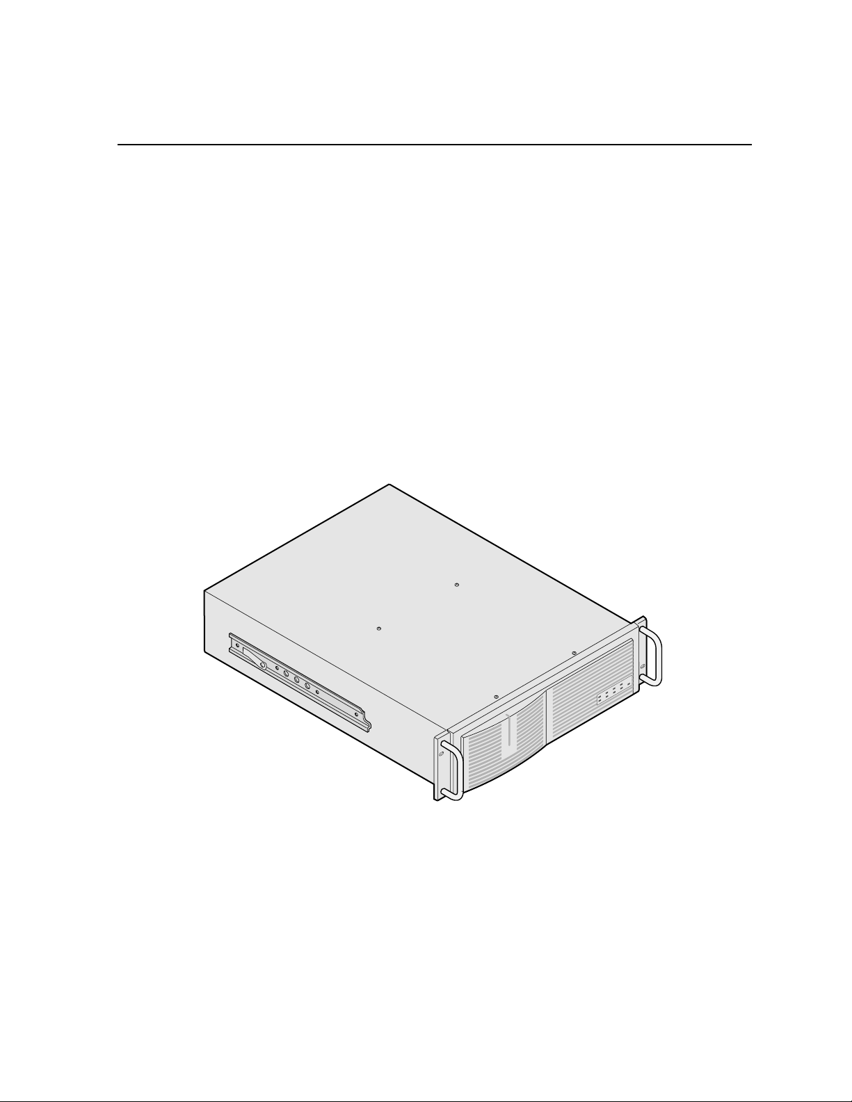
This is the Instruction Manual for the Tektronix PDX208, Disk Expansion Chassis
(Figure 1-1). The manual consists of:
• A description of the PDX208.
• Installation procedures.
• Maintenance procedures.
• Troubleshooting.
• Removal and replacement procedures.
9687-2
Figure 1-1. The PDX208 Disk Expansion Chassis
PDX208 Instruction Manual 1-1
Page 12

Chapter 1 Introduction
Related Documentation
Profile PDR200 Installation Manual
Profile Family User Manual
PDR200 Service Manual
Profile Release Notes
Organization of the Manual
The Installation manual consists of the chapters identified and described below.
Chapter 1 - Introduction: This chapter describes the contents of the manual and the
PDX208 chassis. It includes physical and electrical specifications and environmental
criteria.
Chapter 2 - Installation: This chapter describes the physical installation of the
PDX208 including initial power-on. It includes configuration information.
Chapter 3 - Service: This chapter consists of maintenance information,
troubleshooting procedures, and removal and replacement procedures. The chapter
includes a list of Field Replaceable Units (FRUs) and pin-outs for the rear panel
SCSI-2 connector.
Product Description
The PDX208 expands the capacity of a Profile to store program material. It adds
72GB media storage to your Profile. The amount of disk expansion for program
material storage depends on how your PRX208 is connected to your Profile, and how
it is configured through the Disk Utility on the Profile.
Each PDX208 contains eight 9GB hard disk drives. This provides two banks of four
drives (36GB each) to support a Profile with two Enhanced Disk Recorder boards
(Master and Slave). The PDX208 may be configured to provide one bank of eight
drives (72GB) to support a Profile with only the Master Enhanced Disk Recorder
board. Application software in the Profile provides control of the PDX208 usage.
Product features and front panel indicators are discussed below.
1-2 PDX208 Instruction Manual
Page 13
Product Features
Features of the PDX208 are:
• Contains its own power supply and connection to source power.
• Mounts on rack slides for installation in a standard equipment rack.
• Control interface and media transfers from and to the Profile are through SCSI-2
cables connected to the rear panel (see Chapter 2, Installation).
• Front panel indicators.
Indicators
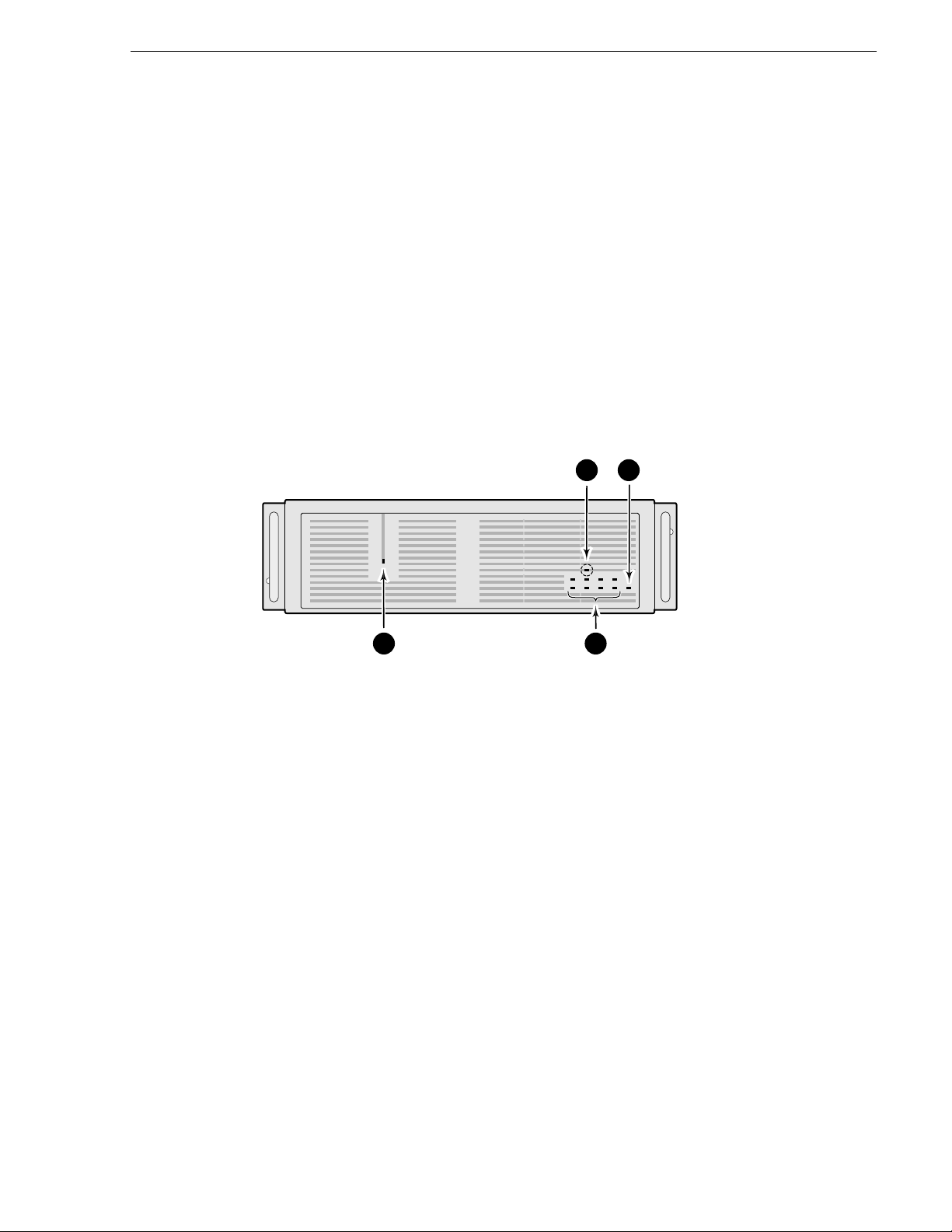
The following describes the indicators on the PDX208 front panel (see Figure 1-2).
Product Features
34
9687-17
1 2
Figure 1-2. PDX208 Indicators
Power indicator; green LED lighted when the power switch on the rear panel is
➊
On.
Disk Activity indicators; two banks of four green LEDs show disk activity. Each
➋
bank corresponds to a SCSI bus with four disk drives. Mapped to the physical
location of each hard disk drive in the chassis, the LEDs flash when activity
occurs on the associated disk. A LED that never flashes on or remains on may
indicate a problem with the associated disk.
System Fault indicator; red LED off during normal operation. Lights to indicate
➌
either a terminal power failure or (with
Fan Fault indicator (behind the front panel bezel and only visible with the bezel
➍
removed);
indicate
red LED off during normal operation. Lights (along with 3 above) to
a fan failure.
4 below lighted) a fan failure.
PDX208 Instruction Manual 1-3
Page 14

Chapter 1 Introduction
Specifications
The following tables list the electrical and physical specifications and environmental
criteria for the PDX208.
Definition of Terms Used in Tables
The following terms apply to the PDX208 as they appear in the following tables.
Specification -A document or a section of a document that lists and describes
characteristics and performance requirements of equipment and certain program
material.
REQUIREMENT: (Performance Requirement)
characteristic usually in limit form.
SUPPLEMENTAL DATA: - Statements that explain performance requirements or
provide performance information. These are not considered to be statements of
guaranteed performance and are not ordinarily supported by a performance check
procedure.
Electrical Specifications
Table 1-1 lists the electrical specifications for the PDX208.
Table 1-1. Power Source
Specifications Description
Electrical Rating Requirement: 100 -240V, 50/60 Hz, 3A maximum
Supply Type Supplemental Data:Single Phase
Supply Connection Supplemental Data:Detachable cord set
Power Consumption Supplemental Data:<300 VA
- A statement that defines a
1-4 PDX208 Instruction Manual
Page 15
Mechanical Specifications
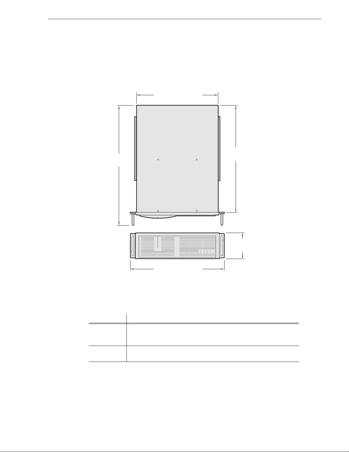
Figure 1-3 shows the dimensions of the PDX208 and Table 1-2 lists and the
mechanical specifications.
22.50 in
(57.25 cm)
Mechanical Specifications
16.87 in. (42.85 cm.)
20.25 in
(51.44 cm)
5.25 in
(13.34 cm)
19.00 in (48.26 cm)
Figure 1-3. Mechanical Specifications
Table 1-2. PDX208 Mechanical Specifications
Specification Description
Dimensions Requirement: Height: 5.250 inches (13.335 centimeters)
Width: 19.000 inches (48.260 centimeters)
Depth: 22.500 inches (57.150 centimeters)
Weight Requirement: Net: 51.5 pounds (23.360 kilograms)
Shipping:71 pounds (32.205 kilograms)
9687-1
PDX208 Instruction Manual 1-5
Page 16

Chapter 1 Introduction
Environmental Criteria
Table 1-3. Environmental Criteria
Characteristics Description
Operating Temperature Requirement: 10° to 40°C (+50° to 104°F)
Storage Temperature Requirement: -40° to 60°C (-40° to 140°F)
Operating Altitude Requirement: To 10,000 feet (3048 meters)
Supplemental Data:IEC 950 compliant to 2000 meters
Storage Altitude Requirement: To 40,000 feet (12,192 meters)
Vibration Requirement: Military Specification: Mil-T-28800D, Class 6 (Non-Operating Only)
Mechanical Shock Military Specification: Mil-T-28800D, Class 6 (Non-Operating Only)
Transportation Requirement: Qualified under NSTA Test Procedure 1A, Category II (18 inch drop)
Equipment Type Supplemental Data:Information Technology
Equipment Class Supplemental Data:Class I
Installation Category Requirement: Category II Local level mains, appliances, portable equipment
Pollution Degree Requirement: Level 2 operating environment, indoor use only
Humidity Requirement: Operating 8% - 90%
Non-Operating 8% - 90%
Maximum Wet Bulb Temperature 29° operating
Supplemental Data:Do not operate with visible moisture on the circuit boards
1-6 PDX208 Instruction Manual
Page 17

Chapter
2
Installing
This chapter describes the physical installation of your PDX208 and configuring it for
use with your Profile. The information includes:
• Mounting the PDX208 in the equipment rack.
• Making PDX208 rear panel cable connections.
• Turning power On.
• Configuring the PDX208.
Rack Mounting
The PDX208 installs in a standard 19-inch equipment rack. Rack slides allow the
PDX208 to slide in and out without having to remove it from the rack. However, if
the rack does not already have rack slides installed, or if the slides are not correctly
positioned, you will have to use those shipped with the PDX208.
When determining the location of the PDX 208 in the rack, bear in mind that the unit
weighs approximately 51.5 pounds. Observe the following warnings:
WARNING: To prevent injury, two people are required to lift the PDX208. It is too
!
heavy for one person to install in the rack.
WARNING: To prevent serious injury, insure that the rack is anchored to the floor
!
so that it cannot tip over when the PDX 208 is extended out of the rack.
PDX208 Instruction Manual 2-1
Page 18
Chapter 2 Installing
Mounting the Slides in the Rack
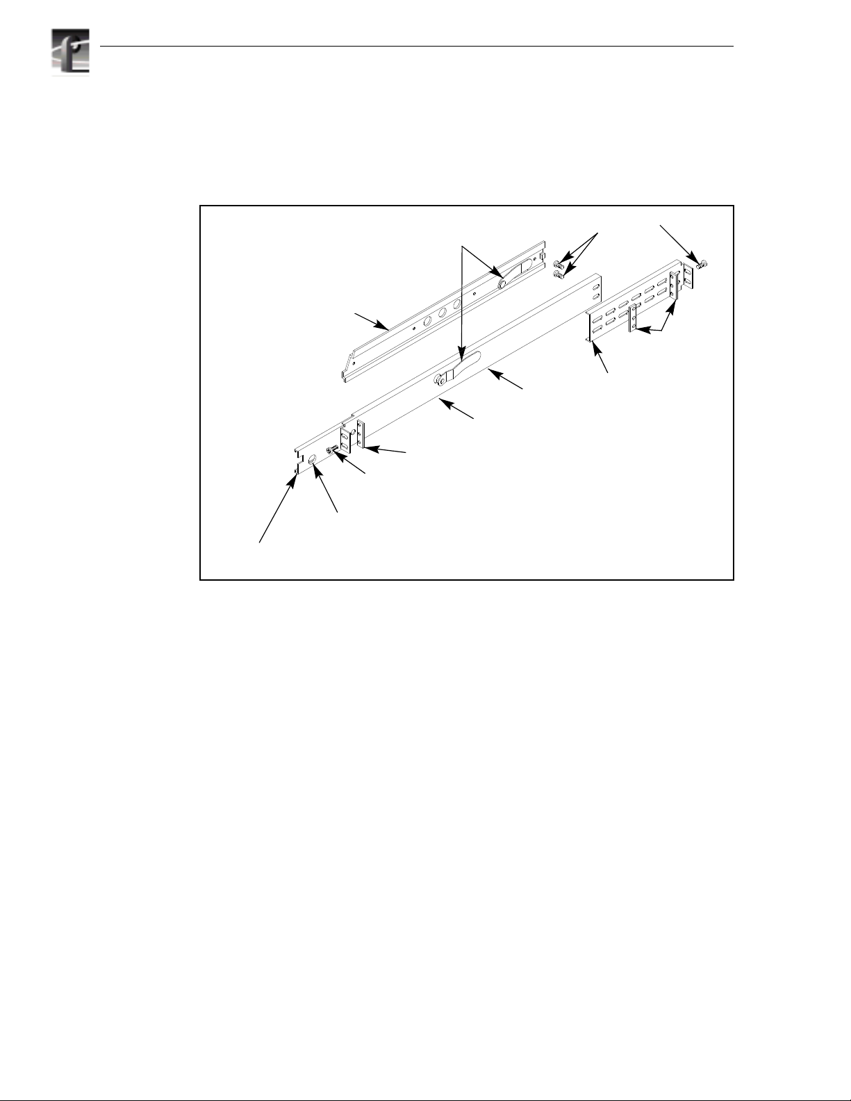
Figure 2-1 shows the components of a right-hand rack slide set. Note that the chassis
section is already attached to the PDX208. When mounting rack slides in the
equipment rack, bear in mind that the PDX208 occupies 3 RUs.
PDX 208 Chassis Section
10-32 PHS
Screw
Stop Latch
Hole
Intermediate
Section
Figure 2-1. Rack Slide Set for Right Side of Chassis and Rack
Automatic
Latches
Stationary
Section
Rack
Section
Flat Nut Bar
NOTE: Right-hand and left-hand stationary section is designated by the
RH and the LH marked on the rails. Stop latch holes should be towards
the bottom when slides are in place. (The right-hand rail is shown above.)
10-32 PHS
Screw
Flat
Nut
Bars
Rear
Mounting
2-2 PDX208 Instruction Manual
Page 19
Mounting the Slides in the Rack
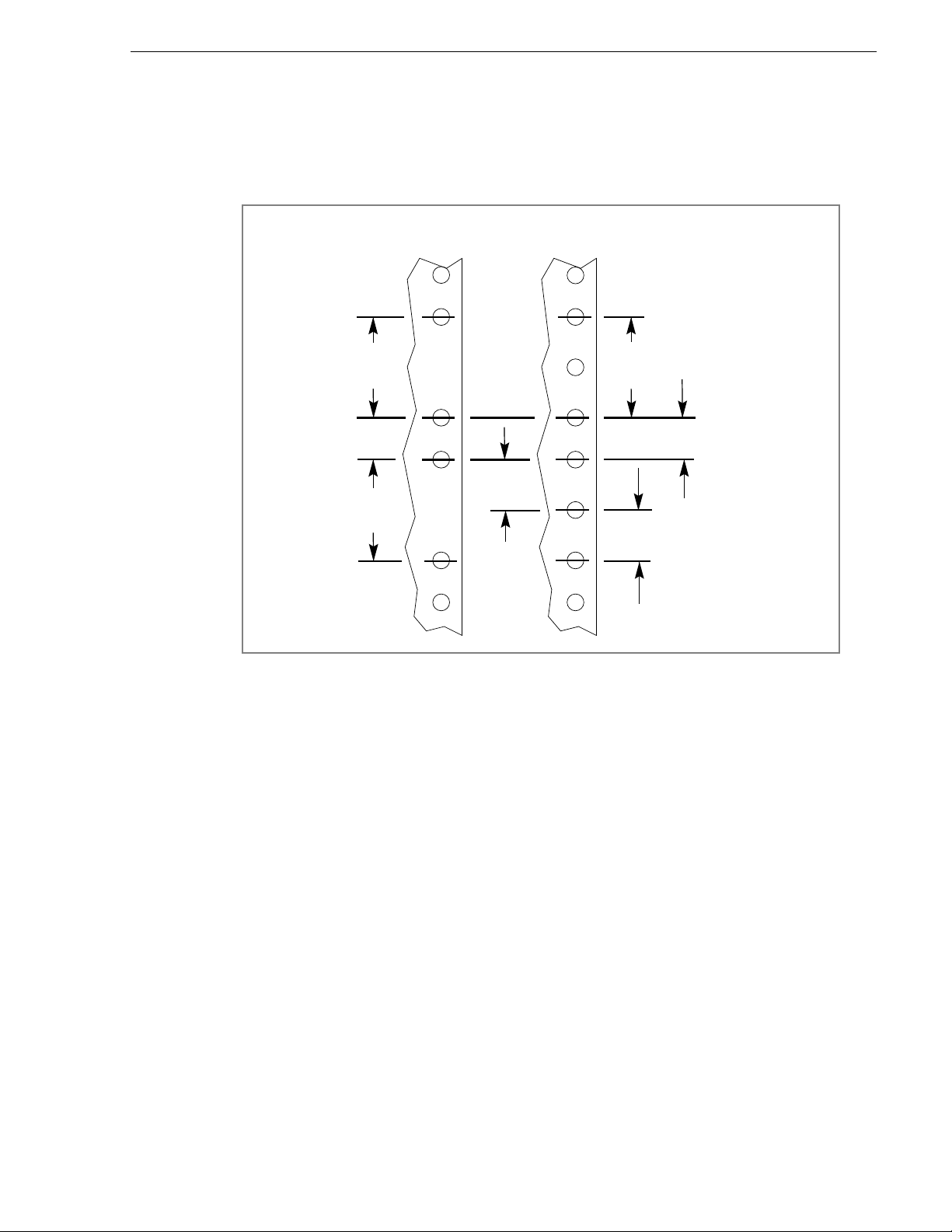
Locate the proper rack holes as shown in Figure 2-2. Notice that the hole spacing can
vary with the rack type. When mounting the slides in racks with EIA spacing, make
sure that the slides are attached to the 0.5-inch spaced holes.
MIL STD 189
SPACING
1.250 in
(3.18 cm)
0.625 in
1.250 in
(3.18 cm)
Figure 2-2. Spacing for Mounting Holes in a Rack
(1.59 cm)
“UNIVERSAL” SPACING
EIA RS310, RETMA
1.250 in
(3.18 cm)
0.625 in
(1.59 cm)
0.500 in
(1.27 cm)
PDX208 Instruction Manual 2-3
Page 20
Chapter 2 Installing
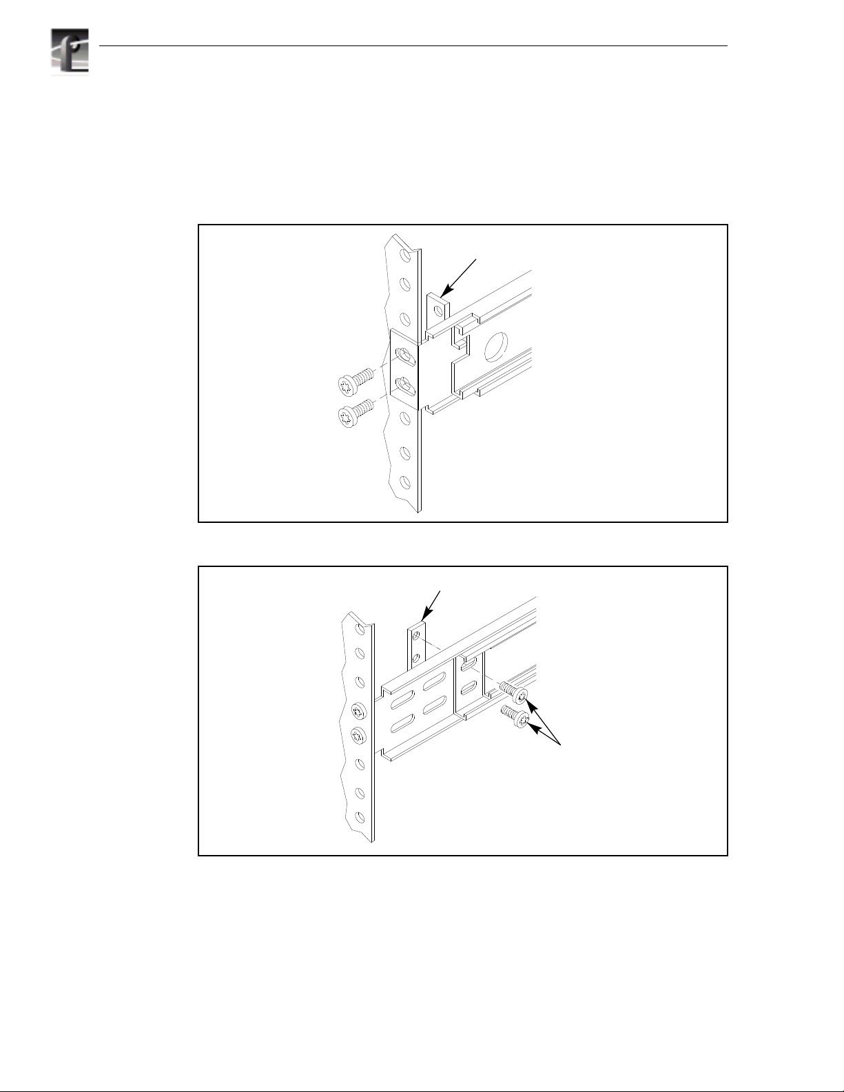
Mount the slides using the enclosed hardware as shown in Figure 2-2. Figures 2-3 and
2-4 show the front and rear slide mounting details for both deep and shallow racks.
Make sure the stationary sections are horizontally aligned and are level as well as
parallel to each other.
(Use if the front rail is not tapped)
Figure 2-3. Front Slide Mounting Detail
BAR NUT
BAR NUT
2-4 PDX208 Instruction Manual
PNH
SCREWS
REAR RACK RAIL
Figure 2-4. Rear Slide Mounting Detail
Page 21

Mounting the PDX208
In addition to having room to make cable connections, the PDX208 requires six
inches (15.25 cm) of clearance behind the rear panel for connectors and cable bends.
Adequate air flow must also be assured around the chassis to provide sufficient
cooling. (Operating ambient temperature will affect the amount of air circulation
required to keep the PDX208 within its temperature limitations.)
1. Pull the slide-out section to the fully extended position. See Figure 2-5.
WARNING: To prevent injury, two people are required to lift the PDX208. The
!
PDX208 is too heavy for one person to install in the rack.
WARNING: To prevent serious injury, insure that the rack is anchored to the floor
!
so that it cannot tip over when the PDX 208 is extended out of the rack.
2. Insert the ends of the chassis sections into the slide-out sections.
3. Push the chassis toward the rack until the chassis sections lock into the
intermediate sections.
4. Press the stop latches in the intermediate sections and push the chassis toward the
rack until the latches snap into their holes.
Mounting the PDX208
5. Again, press the stop latches and push the cabinet fully into the rack.
6. Insert and tighten the front panel retaining screws.
Rack Slide Adjustments
After installation, binding may occur if the slides are not properly adjusted. To adjust
the slides:
1. Slide the chassis out approximately 10 inches.
2. Slightly loosen the mounting screws holding the slides to the front of the rack and
allow the slides to seek an unbound position.
3. Tighten the mounting screws and check the slides for smooth operation by sliding
the chassis in and out of the rack several times.
4. Tighten the front panel retaining screws once the cabinet is in place within the rack
to complete the installation.
Stop Latch
Figure 2-5. Rack Slide Stop Latch
PDX208 Instruction Manual 2-5
Page 22

Chapter 2 Installing
Making Cable Connections
All cables connect to the PDX208 SCSI Bus 1 and SCSI Bus 2 connectors on the rear
panel as shown in Figure 2-6.
SCSI Bus 1
connectors
Figure 2-6. PDX 208 Cable Connections
PDX208 to Profile Connections
The following examples show typical PDX208 connections to a Profile.
Connecting One PDX208 to One 4-Channel Profile
Figure 2-7 shows an example of PDX208 connections to a 4-channel PDR200
Profile. If connecting to a PDR100 Profile, see the configuration stickers below the
rear panel slots for the locations of the Disk Recorder boards.
SCSI Bus 2
connectors
9687-18
PDR200
J10 J9
PDX208
SCSI Cable
Terminator
9687-3
Figure 2-7. Example of PRX208 Cable Connections to a 4-channel Profile
2-6 PDX208 Instruction Manual
Page 23

PDX208 to Profile Connections
To connect one PDX208 to one 4-channel PDR200, refer to Figures 2-6 and 2-7 and:
1. Connect a SCSI cable from the PDR200 rear panel connector on the Master
Enhanced Disk Recorder board (Slot J9) to one of the SCSI Bus 2 connectors on
the PDX208.
2. Connect another SCSI cable from the PDR200 rear panel connector on the Slave
Enhanced Disk Recorder board (Slot J10) to one of the SCSI Bus 1 connectors on
the PDX208.
3. Connect Terminators to the unused SCSI Bus 1 and SCSI Bus 2 connectors on the
PDX208.
The PDX208 connection shown in Figure 2-7 provides four 9GB disk drives to the
SCSI A bus on the Master Disk Recorder board and four 9GB disk drives to the SCSI
C bus on the Slave Disk Recorder board (or SCSI B bus on a PDR100).
PDX208 Instruction Manual 2-7
Page 24

Chapter 2 Installing
Connecting a PDX208 to a 2-Channel Profile
Figure 2-8 shows a PDX208 connection to a 2-channel Profile (i.e., without the Slave
Disk Recorder board). If connecting to a PDR100 Profile, see the configuration
stickers below the rear panel slots for the location of the Disk Recorder board. To
connect a PDX208 to a 2-channel Profile, refer to Figure 2-6 and Figure 2-8 and:
1. Connect a SCSI cable from the SCSI A bus on the Master Disk Recorder board
(Slot J9) to one of the SCSI Bus 2 connectors on the PDX208.
2. Connect another SCSI cable from the second SCSI Bus 2 connector on the
PDX208 to one of the SCSI Bus 1 connectors on the PDX208 as shown in Figure
2-8.
3. Connect a Terminator to the unused SCSI Bus 1 connector on the PDX208.
PDR200
J9
PDX208
SCSI Cable
Terminator
9687-4
Figure 2-8. Example of PRX208 Cable Connections to a 2-channel Profile
The connection shown in Figure 2-8 provides eight 9GB disk drives to the SCSI A
bus of the 2-channel Profile.
2-8 PDX208 Instruction Manual
Page 25

Connecting Two PDX208s to One 4-Channel Profile
Figure 2-9 shows two PDX208s connected to a 4-channel Profile. If connecting to a
PDR100 Profile, see the configuration stickers below the rear panel slots for the
locations of the Disk Recorder boards. To connect two PDX208s to a 4-channel
Profile, refer to Figure 2-6 and Figure 2-9 and:
1. Connect a SCSI cable from the SCSI A bus on the Master Disk Recorder board
(Slot J9) to one of the SCSI Bus 2 connectors on the first PDX208.
2. Connect a SCSI cable from the second SCSI Bus 2 connector on the first PDX208
to one of the SCSI Bus 1 connectors on the first PDX208.
3. Connect a Terminator to the unused SCSI Bus 1 connector on the first PDX208.
4. Connect a SCSI cable from the SCSI C bus on the Slave Disk Recorder board (Slot
J10) to one of the SCSI Bus 1 connectors on the second PDX208.
5. Connect a SCSI cable from the second SCSI Bus 1 connector on the second
PDX208 to one of the SCSI Bus 2 connectors on the second PDX208.
6. Connect a Terminator to the unused SCSI Bus 2 connector on the second PDX208.
PDX208 to Profile Connections
PDR200
J10 J9
First PDX208
Second PDX208
SCSI Cable
Terminator
9687-5
Figure 2-9. Two PRX208s Connections to a 4-channel Profile
The connection shown in Figure 2-9 provides eight 9GB disk drives to the SCSI A
bus and eight 9GB disk drives to the SCSI C bus on the 4-channel PDR200 Profile
(or the SCSI B bus on the 4-channel PDR100 Profile).
PDX208 Instruction Manual 2-9
Page 26

Chapter 2 Installing
Power Connections
Power Source
The PDX208 operates from a single-phase power source having one of its
current-carrying conductors at or near earth ground (the neutral conductor). A fuse on
the line conductor provides over-current protection. Tektronix does not recommend
connection to systems whose power source has both current carrying conductors live
with respect to ground, such as phase-to-phase in multi-phase systems.
Source Power Frequency and Voltage Ranges
The PDX208 operates at line frequencies of 50 or 60 Hz at nominal voltages from 100
to 240 VAC. Table 2-1 lists the power cord options available. Figure 2-10 shows the
location of the power cord connector and the power switch.
Table 2-1. Power Cord Options for the PDX208
Power Plug Description
Standard 120 V, 3-prong power plug on a 2.5 meter long
power cord. For use with common ground systems in
North America.
Option A1 Universal European 230V/10A power plug on
a 2.5 meter long power cord.
Option A2 United Kingdom 230V/10A power plug on a
2.5 meter long power cord.
Option A3 Australian 230V/10A power plug on a 2.5
meter long power cord.
Insure that the power switch is set to 0 (Off). Attach the power cord from the PDX208
to the appropriate power source.
2-10 PDX208 Instruction Manual
Page 27

Power Cord
connector
Power
switch
Figure 2-10. PDX208 Power Cord Connector and Switch
Configuring the PDX208
This concludes the installation of your PDX208. Refer to the Profile Family User
Manual,Using the Profile Disk Utility, for detailed information about configuring the
PDX208 for use with your Profile. Note that there may be differences between
configuring the PDX208 for:
Configuring the PDX208
9687-6
• Use with a PDR200 and use with a PDR100.
• Use with a 4-channel PDR100 and use with a 2-channel PDR100, both of which
require Profile software v2.1 or higher.
In addition, consider the following when configuring your PDX208:
- The disk drives in the PDX208 can be combined with Profile disk drives to form
one dataset.
- If you partition the PDX208 as an external dataset and using third party
software, insure that the software recognizes both internal and external datasets.
- The system recognizes the capacity of video disk drives at the smallest unit. If
connecting the PDX208 to a PDR100 with 4 GB drives, configure the PDX208
as a separate dataset. Making one dataset of Profile 4 GB drives and PDX208 9
GB drives limits PDX208 expansion to 32 GB (8 x 4 GB) instead of 72 GB (8
x 9 GB).
PDX208 Instruction Manual 2-11
Page 28

Chapter 2 Installing
2-12 PDX208 Instruction Manual
Page 29

WARNING
THE FOLLOWING SERVICING INSTRUCTIONS
ARE FOR USE BY QUALIFIED PERSONNEL
ONLY. TO AVOID PERSONAL INJURY, DO NOT
PERFORM ANY SERVICING OTHER THAN THAT
CONTAINED IN OPERATING INSTRUCTIONS
UNLESS YOU ARE QUALIFIED TO DO SO.
REFER TO OPERATORS SAFETY SUMMARY
AND SERVICE SAFETY SUMMARY PRIOR TO
PERFORMING ANY SERVICE.
Page 30

Page 31

Service Safety Summary
Service Safety Summary
Review the following safety precautions to avoid injury and prevent
damage to this product or any products connected to it.
Only qualified personnel should perform service procedures.
While using this product, you may need to access other parts of the
system. Read the General Safety summary in other system manuals for
warnings and cautions related to operating the system.
Safety Terms and Symbols
Terms in This
Manual
!
!
Terms on the
Product
!
!
Symbols on the
Product
These terms may appear in this manual:
WARNING:Warning statements identify conditions or practices that can
result in personal injury or loss of life.
CAUTION: Caution statements identify conditions or practices that can
result in damage to the equipment or other property.
These terms may appear on the product:
DANGER indicates a personal injury hazard immediately accessible as
one reads the marking.
WARNING indicates a personal injury hazard not immediately
accessible as you read the marking.
CAUTION indicates a hazard to property including the product.
The following symbols may appear on the product:
DANGER high voltage
Protective ground (earth) terminal
!
ATTENTION – refer to manual
PDX208 Instruction Manual
Page 32

PDX208 Instruction Manual
Page 33

Chapter
3
Service
This chapter consists of:
• Maintenance information.
• Troubleshooting procedures.
• Removal and replacement procedures for Field Replaceable Units (FRUs).
• Replaceable Parts List
• SCSI connector pin-outs
PDX208 Instruction Manual 3-1
Page 34

Chapter 3 Service
Maintenance
There is no specifically required periodic maintenance for the PDX208. Cleaning the
exterior is on an “as needed” basis. Checking and cleaning or replacing the air filter
will depend on the operating environment. Procedures for doing these tasks are
discussed below.
WARNING: If a liquid of any kind is spilled onto the PDX208, immediately turn
!
power Off and insure that both the inside and the outside are completely dry before
re-applying power.
Cleaning
Clean the PDX208 often enough to prevent dust or dirt from accumulating. Dirt acts
as a thermal insulating blanket that prevents effective heat dissipation, and can
provide high-resistance electrical leakage paths between conductors or components
in a humid environment.
Exterior
Clean the dust from the outside by wiping with a soft cloth or small brush. A brush is
especially useful to remove dust from around the connectors. Hardened dirt may be
removed with a cloth dampened in water or a 50% isopropyl alcohol solution. Do not
use an abrasive cleaner.
Interior
!
Clean the interior by loosening accumulated dust with a dry, soft brush. Once the dirt
is loosened, remove it with low-pressure air (high-velocity air can damage some
parts). Remove hardened dirt or grease with a cotton-tipped applicator dampened with
a solution of mild detergent and water. Do not use an abrasive cleaner. If the circuit
board assembly must be removed for cleaning, follow the removal/replacement
instructions.
After cleaning, allow the interior to thoroughly dry before applying power to the unit.
CAUTION: Do not allow water to get inside any enclosed assembly or component.
Do not clean any plastic materials with organic cleaning solvents, such as benzene,
toluene, xylene, acetone, or similar compounds, because they may damage the
plastic.
3-2 PDX208 Instruction Manual
Page 35

Cleaning and Changing the Air Filter
In a humid environment, the air filter behind the front bezel of the PDX208 will
usually require more frequent attention than in a dryer environment. Figure 3-1 shows
the location of the filter which requires removal of the front bezel. To remove the air
filter for cleaning or replacement, refer to Figure 3-1, and proceed as follows:
Cleaning and Changing the Air Filter
Unsnap Front
1
Panel Bezel
Air Filter
Remove
Air Filter
Air Filter
2
9687-8
Figure 3-1. PRX208 Air Filter Removal
1. Unsnap the front panel bezel by firmly pulling away from the front panel.
2. Detach the air filter from the studs behind the bezel.
3. If cleaning, use a low pressure air supply to blow contaminants out of the filter.
4. Attach the filter to the bezel as shown in Figure 3-1.
5. Position the front panel bezel mounting posts over the holes in the front panel and
snap the bezel back in place.
PDX208 Instruction Manual 3-3
Page 36

Chapter 3 Service
Troubleshooting
If you suspect that the PDX208 is the cause of a Profile-related problem:
• Check all SCSI cable connections.
• Check the power cord connection.
• Insure the On/Off switch is On.
• Insure that the power switch and line filter are good.
• Check the indicators on the front panel (Figure 3-2) which provide information to
assist in fault isolation.
If it is necessary to replace a component, see Removal and Replacement Procedures
later in this chapter.
Refer to Figure 3-2 in the following discussions.
Power On LED Disk activity
Figure 3-2. PDX208 Front Panel Indicators
Power On Indicator
The chassis power green LED indicator should be On.
If Off
- Power Supply bad, replace Power Supply.
- Fuse F1 or F3 on SCSI Distribution board blown, replace SCSI Distribution
board.
- LED cable assembly bad, replace cable assembly.
Fan failure LED
(located behind bezel)
System fault
LED
9687-7
LEDs
3-4 PDX208 Instruction Manual
Page 37

Disk Activity Indicators
These eight green LED indicators show Disk Activity.
If one or more LED(s) is frozen On or Off.
- Profile crash, see Profile Family User Manual or Profile Service Manual.
- One or more bad disk drives. One bad disk drive will, after a few seconds, cause
all the Disk Activity LEDs to freeze On or Off. Turn PDX208 power off, then,
while observing these LEDs, turn power back on. The bad disk drive will not
show activity, replace that drive.
- SCSI Distribution board bad, replace.
- An external or internal cable is loose or bad. Check all cables, reconnect or
replace as necessary.
All Disk Activity LEDs go off, but PDX208 remains operative.
- Fuse F3 on SCSI Distribution board blown, replace SCSI Distribution board.
Disk Activity LEDs do not flash.
- LED Board bad, replace LED Board.
- Disk Drive LEDs cable bad, replace.
Disk Activity Indicators
System Fault Indicator
The System Fault red LED indicator may be On under the two conditions listed
below. Remove the front bezel to determine which condition is present.
1. System Fault LED On
terminal power fuses on the SCSI Distribution board has blown, replace SCSI
Distribution board.
2. System Fault LED On
fans is bad. Turn PDX208 power Off, remove the top cover (see Removal and
Replacement Procedures), briefly turn power back On. Replace whichever fan is
not turning.
Fan Fault Indicator
The Fan fault red LED indicator is behind the front panel bezel. See above description
on System Indicator.
but Fan Fault indicator LED Off, one (or more) of the
and the Fan Fault indicator LED On, one (or more) of the
PDX208 Instruction Manual 3-5
Page 38

Chapter 3 Service
Removal and Replacement Procedures
This section identifies the replaceable parts of the PDX208 and the procedures to
remove and replace them.
NOTE: Do not discard any hardware unless specifically instructed to do so.
WARNING: Insure that the power cord is disconnected prior to performing any
!
removal and replacement procedure.
Replaceable Parts
Table 3-1 lists the PDX208 replaceable parts. Figure 3-3, keyed to Table 3-3, shows
the parts.
Table 3-1. PDX208 Replaceable Part List
Key Part Number Description
1 119-5195-XX Power Supply
2 119-4827-XX Fan, DC
3 671-4120-XX SCSI Distribution Board, Single Ended
4 119-5638-XX Video Disk Drive, 9 GB, Single Ended
5 407-4478-XX Disk Drive Caddie
6 174-3748-XX Cable, Power Supply to SCSI Distribution Board
7 174-3612-XX Cable, Line In to Power Supply
8 174-3586-XX Cable, Line In/Switch to Power Supply
9 174-3668-XX Cable, SCSI Internal/External
10 174-3751-XX Cable, Disk Drive to LED
11 671-3948-XX LED Board Assy, PDX208
12 174-3616-XX Cable Assy, LED
13 378-0432-XX Air Filter
14 333-4222-XX Front Bezel
Removal and replacement procedures begin with the parts listed below, which do not
require removal of the PDX208 from the equipment rack.
• Front panel bezel (item 14 in Table 3-1)
• Air Filter (item 13 in Table 3-1)
• Video Disk Drive (item 4 in Table 3-1)
• Disk Drive Caddie (item 5 in Table 3-1)
• LED board assembly (item 11 in Table 3-1)
• LED Cable Assembly (item 12 in Table 3-1)
3-6 PDX208 Instruction Manual
Page 39

Replaceable Parts
1
2
6
3
4
7
8
9
5
10
12
Figure 3-3. Replaceable Parts
9687-23
11
13
14
PDX208 Instruction Manual 3-7
Page 40

Chapter 3 Service
Removing and Replacing the Front Panel Bezel and Air Filter
For front panel bezel and air filter removal/replacement, see Cleaning and Changing
the Air Filter previously discussed in this chapter.
Removing and Replacing a Disk Drive
A disk drive caddie holds each disk drive in place (items 4 and 5 in Table 3-1). If in
troubleshooting the PDX208, a disk drive is determined to be bad, the hinged front
panel must be loosened and lowered, and the appropriate caddie must be removed
before the disk drive can be removed and replaced. It is not necessary to remove the
PDX208 from the rack to perform this procedure. See Figure 3-4 to lower the front
panel and Figure 3-5 to remove the caddie and disk drive.
Remove screws (14)
1
Open hinged
2
front panel
3-8 PDX208 Instruction Manual
9687-12
Figure 3-4. Lowering the Front Panel
Page 41

Removing and Replacing a Disk Drive
Slide drive out
1
Remove drive
2
from bracket
9687-10
Figure 3-5. PDX208 Disk Drive Caddie and Disk Drive Removal
To remove a caddie and disk drive:
1. Unsnap the front panel bezel by firmly pulling away from the front panel (Figure
3-1).
2. Remove the retaining screws from the front panel. (Figure 3-4) (These are also
caddie retaining screws.)
3. Lower the front panel.
4. Grasp the appropriate caddie, pull straight out of the chassis, and place on a level,
static-proof surface (Figure 3-5).
5. Remove the drive mounting screws and remove the drive from the caddie.
To install a disk drive and reinstall a caddie:
1. Mount the new drive in the caddie using the screws previously removed from the
caddie (Figure 3-5).
2. Slide the caddie into the chassis.
3. Raise the front panel and secure it with the screws previously removed (Figure
3-4).
4. Position the front panel bezel mounting posts over the holes in the front panel and
press firmly until the bezel snaps back in place (Figure 3-1).
PDX208 Instruction Manual 3-9
Page 42

Chapter 3 Service
Removing and Replacing the LED Board
The LED Board (item 11 in Table 3-1) is on the front panel It is not necessary to
remove the PDX208 from the rack to perform this procedure. Figure 3-6 shows
removal of the LED board.
Unsnap LED Board from
1
the two mounting posts
Pull LED out of
2
front panel socket
Unplug cabling and
3
remove LED board
9687-11
Figure 3-6. PDX208 LED Board and Cable Removal
3-10 PDX208 Instruction Manual
Page 43

Removing and Replacing the LED Cable Assembly
To remove LED board:
1. Unsnap the front panel bezel by firmly pulling away from the front panel (Figure
3-1).
2. Remove the retaining screws from the front panel. (Figure 3-4) (These are also
caddie retaining screws.)
3. Lower the front panel.
4. Unsnap the LED board from the mounting posts (Figure 3-6) by pulling the board
straight up from the front panel.
5. Disconnect the cables from the LED board.
To install the LED board:
1. Connect the previously removed cables to the LED board.
2. Position the LED board over the mounting posts in the front panel and firmly press
down until the LED board snaps into place (Figure 3-6).
3. Raise the front panel and secure with the screws previously removed (Figure 3-4).
4. Position the front panel bezel mounting posts over the holes in the front panel and
press firmly until the bezel snaps back in place (Figure 3-1).
Removing and Replacing the LED Cable Assembly
This cable assembly (item 12 in Table 3-1) connects from the LED board to the front
panel power LED. It is not necessary to remove the PDX208 from the rack to perform
this procedure. Figure 3-6 shows removal of the LED cable assembly. To remove
LED cable assembly:
1. Unsnap the front panel bezel by firmly pulling away from the front panel (Figure
3-1).
2. Remove the retaining screws from the front panel. (Figure 3-4) (These are also
caddie retaining screws.)
3. Lower the front panel.
4. Unsnap the LED board from the mounting posts (Figure 3-6) by pulling the board
straight up from the front panel.
5. Disconnect the LED cable assembly from the LED board (Figure 3-6).
6. Pull the LED end of the cable out of the front panel socket.
To install the LED board:
1. Connect the new LED cable assembly to the LED board (Figure 3-6).
2. Position the LED board over the mounting posts in the front panel and firmly press
down until the LED board snaps into place (Figure 3-6).
3. Insert the LED end of the cable into the front panel socket.
4. Raise the front panel and secure with the screws previously removed (Figure 3-4).
5. Position the front panel bezel mounting posts over the holes in the front panel and
press firmly until the bezel snaps back in place (Figure 3-1).
PDX208 Instruction Manual 3-11
Page 44

Chapter 3 Service
Removing and Replacing the Disk Drive LEDs Cable
This cable (item 10 in Table 3-1), for the disk drive activity LEDs, connects from the
LED board on the front panel to the SCSI Distribution board. It is not necessary to
remove the PDX208 from the rack to perform this procedure. Figure 3-7 shows the
LED board and cables.
Unplug cable
connectors and
2
remove cable
Remove
LED board
9687-19
Figure 3-7. Disk Drive LEDs Cable Removal
1
To remove the Disk Drive LEDs cable:
1. Unsnap the front panel bezel by firmly pulling away from the front panel (Figure
3-1).
2. Remove the retaining screws from the front panel (Figure 3-4). (These are also
caddie retaining screws.)
3. Lower the front panel.
4. Unsnap the LED board from the mounting posts (Figure 3-6) by pulling the board
straight up from the front panel.
5. Disconnect the Disk Drive LEDs cable from the LED board (Figure 3-7).
6. Remove as many caddies as necessary to reach the Disk Drive LEDs cable where
it connects to the SCSI Distribution board (Figure 3-7). (See Removing a Disk
Drive.)
7. Disconnect the Disk Drive LEDs cable from the SCSI Distribution board.
3-12 PDX208 Instruction Manual
Page 45

To install a new Disk Drive LEDs cable:
1. Connect the new Disk Drive LEDs cable from the LED board to the SCSI
Distribution board (Figure 3-7).
2. Replace the caddies previously removed.
3. Position the LED board over the mounting posts on the front panel and firmly press
down until the board snaps into place (Figure 3-6).
4. Raise the front panel and secure with the screws previously removed (Figure 3-4).
5. Position the front panel bezel mounting posts over the holes in the front panel and
press firmly until the bezel snaps back in place (Figure 3-1).
Removing the Top Cover
Figure 3-8 shows removal of the top cover, which must be removed to access the
interior for removal of other parts. To remove the top cover, refer to Figure 3-8 and:
1. Remove the PDX208 from the equipment rack.
2. Remove the cover mounting screws.
3. Lift the cover up and off the chassis.
Removing the Top Cover
9687-9
Figure 3-8. PDX208 Top Cover Removal
PDX208 Instruction Manual 3-13
Page 46

Chapter 3 Service
Removing the Disk Tray Cover
Figure 3-9 shows removal of the disk tray cover, which must be removed to gain
access for removal of other parts.
To remove the disk tray cover:
1. Remove the PDX208 from the equipment rack.
2. Remove the top cover (Figure 3-8).
3. Unsnap the front panel bezel (Figure 3-1).
4. Remove the front panel retaining screws and lower the front panel (Figure 3-4).
5. Remove all disk drive caddies (Figure 3-5).
6. Remove the screws and L-brackets, one on each side (Figure 3-9).
7. Remove the Disk Tray cover mounting screws.
8. Slide the Disk Tray cover out through the front of the chassis.
To install the disk tray cover:
1. Slide the Disk Tray cover in through the front of the chassis and secure with the
screws previously removed (Figure 3-9).
2. Install the L-brackets with the screws previously removed.
3. Install all disk drive caddies (Figure 3-5) previously removed.
4. Raise the front panel and secure with the screws previously removed (Figure 3-4).
5. Position the front panel bezel mounting posts over the holes in the front panel and
press firmly until the bezel snaps back in place (Figure 3-1).
6. Replace the top cover (Figure 3-8).
7. Reinstall the PDX208 into the equipment rack.
3-14 PDX208 Instruction Manual
Page 47

Removing the Disk Tray Cover
Remove L-brackets
1
and screws as shown
9687-14
Figure 3-9. PDX208 Disk Tray Cover Removal
Slide forward
2
to remove
2
PDX208 Instruction Manual 3-15
Page 48

Chapter 3 Service
Removing and Replacing a SCSI Cable
Internal SCSI cables (item 9 in Table 3-1) connect from two connectors on each side
of the SCSI Distribution board to the two rear panel SCSI connectors on the same side
of the chassis. Figure 3-10 shows removal of an internal SCSI cable.
1
Unplug connectors on
1
both ends of SCSI cables
and remove cables
9687-20
Figure 3-10. Removal of a SCSI Cable
3-16 PDX208 Instruction Manual
Page 49

Removing and Replacing a SCSI Cable
To remove an internal SCSI cable:
1. Remove the PDX208 from the equipment rack.
2. Remove the top cover (Figure 3-8).
3. Remove the Disk Tray cover (Figure 3-9).
4. If necessary, remove disk caddie(s).
5. Disconnect the bad SCSI cable connector from the SCSI Distribution board (Figure
3-10).
6. Disconnect the connector at the other end of the bad SCSI cable from the rear
panel.
To install a SCSI cable:
1. Connect the SCSI cable from the appropriate rear panel connector to the
appropriate SCSI connector on the SCSI Distribution board (Figure 3-10).
2. Install any disk caddies previously removed.
3. Install the Disk Tray cover (Figure 3-9).
4. Replace the top cover (Figure 3-8).
5. Reinstall the PDX208 into the equipment rack.
PDX208 Instruction Manual 3-17
Page 50

Chapter 3 Service
Removing and Replacing the SCSI Distribution Board Power
Cable
Figure 3-11 shows removal of the cable that provides power from the Power Supply
to the SCSI Distribution board (item 6 in Table 3-1).
Remove three
nuts and remove
1
air baffle
Unplug
2
power cable
Black
(two wires)
Red
(two wires)
Black
Yellow w/red stripe
Black w/yellow stripe
Yellow
Yellow (two wires)
Black w/yellow stripe (two wires)
Remove power cable
3
wires from power supply
Figure 3-11. Removal of the SCSI Distribution Board Power Cable
9687-21
3-18 PDX208 Instruction Manual
Page 51

Removing and Replacing the SCSI Distribution
To remove the SCSI Distribution board power cable:
1. Remove the PDX208 from the equipment rack.
2. Remove the top cover (Figure 3-8).
3. Remove the Disk Tray cover (Figure 3-9).
4. Remove as many caddies as necessary to access the Power Supply connector on
the left side of the SCSI Distribution board (Figure 3-5).
5. Disconnect the Power Supply connector from the SCSI Distribution board (Figure
3-11).
6. Remove the air baffle.
7. Disconnect the SCSI Distribution board power cable wires from the Power Supply.
To install the SCSI Distribution board power cable:
1. Connect the cable wires to the left side (as facing the chassis) of the Power Supply
(see the insert in Figure 3-11).
2. Connect the Power Supply cable connector to the SCSI Distribution board.
3. Reinstall the air baffle.
4. Install the Disk Tray cover (Figure 3-9).
5. Replace the top cover (Figure 3-8).
6. Reinstall the PDX208 into the equipment rack.
PDX208 Instruction Manual 3-19
Page 52

Chapter 3 Service
Removing and Replacing the Switch Cable
Figure 3-12 shows removal of the cable assembly that connects the Power Supply to
the rear panel switch (item 8 in Table 3-1). This assembly includes the switch.
1
Remove
shield
Press tabs on top &
3
bottom of power switch
to remove through
rear panel
Remove wires
2
from power
supply
Press tabs on sides of
power cord connector
to remove through
rear panel
Unplug
wires(2)
Remove
ground
wire
Figure 3-12. Removal of the Switch and Line In Cables
3-20 PDX208 Instruction Manual
9687-22
Page 53

Removing and Replacing the Line In Cable
To remove the Switch cable:
1. Remove the PDX208 from the equipment rack.
2. Remove the top cover (Figure 3-9).
3. Remove the shield (Figure 3-12).
4. Disconnect the black and white cable wires from the right side of the Power Supply
(Figure 3-12).
5. Disconnect the switch cable wires from the power connector.
6. Compress the retaining clips on the top and bottom of the switch and remove the
switch out of the chassis through the rear panel.
To install the Switch cable:
1. Install the switch into the chassis through the rear panel with 0 (Off) at the bottom.
2. Connect the switch cable wires to the right side of the Power Supply as shown in
the insert in Figure 3-12.
3. Connect the switch cables wires to the power connector as shown in the insert in
Figure 3-12.
4. Replace the shield.
5. Replace the top cover (Figure 3-8) and reinstall the PDX208 into the rack.
Removing and Replacing the Line In Cable
Figure 3-12 shows the cable assembly that connects the switch to the power cord
connector (item 7 in Table 3-1). This assembly includes the source power connector
and line filter. To remove the power connector cable assembly:
1. Remove the PDX208 from the equipment rack.
2. Remove the top cover (Figure 3-8).
3. Remove the shield (Figure 3-12).
4. Disconnect the power connector wires from the switch assembly (Figure 3-12).
5. Remove the chassis ground wire retaining nut.
6. Compress the retaining clips on each side of the power connector assembly and
remove the connector out of the chassis through the rear panel.
To install the Line In cable assembly:
1. Install the Line In assembly into the chassis through the rear panel with the ground
contact of the connector to the near side of the chassis.
2. Connect the power connector cable wires to the switch assembly as shown in the
insert in Figure 3-12.
3. Attach the chassis ground wire as shown in Figure 3-12.
4. Replace the shield (Figure 3-12).
5. Replace the top cover (Figure 3-8) and reinstall the PDX208 into the rack.
PDX208 Instruction Manual 3-21
Page 54

Chapter 3 Service
Removing and Replacing the Power Supply
Figure 3-13 shows removal of the Power Supply (item 1 in Table 3-1).
Remove four screws from
rear panel and remove
power supply.
4
Remove three
nuts and remove
1
air baffle
Remove shield and
3
detach two wires
Black
(two wires)
Red
(two wires)
Black
Yellow w/red stripe
Black w/yellow stripe
Yellow
Yellow (two wires)
Black w/yellow stripe (two wires)
Remove power cable
2
wires from power supply
Figure 3-13. PDX208 Power Supply Removal
9687-16
3-22 PDX208 Instruction Manual
Page 55

Removing and Replacing the Power Supply
To remove the power supply:
1. Remove the PDX208 from the equipment rack.
2. Remove the top cover (Figure 3-8).
3. Remove the Disk Tray cover (Figure 3-9).
4. Remove the shield from the right side of the Power Supply (Figure 3-13)
5. Remove the mounting nuts from the air baffle and lift the baffle up and out of the
chassis (Figure 3-13).
6. Remove the Power Supply mounting screws from the rear panel and lift the Power
Supply up and out of the chassis just enough to access the cable wire connections
on each side of the Power Supply.
7. Disconnect the SCSI Distribution board cable wires from the left side of the Power
Supply (Figure 3-13).
8. Disconnect the black and white Switch cable wires from the right side of the Power
Supply (Figure 3-13).
9. Lift the Power Supply completely free of the chassis.
To reinstall the power supply:
1. Connect the cable wires from the Switch to the right side of the Power Supply
(Figure 3-13).
2. Connect the SCSI Distribution board cable wires to the left side of the Power
Supply (Figure 3-13).
3. Position the Power Supply at the rear panel and mount with the screws previously
removed (Figure 3-13).
4. Replace the shield.
5. Replace the air baffle using the mounting nuts previously removed.
6. Replace the top cover (Figure 3-8).
7. Reinstall the PDX208 into the equipment rack.
PDX208 Instruction Manual 3-23
Page 56

Chapter 3 Service
Removing and Replacing a Fan
Figure 3-14 shows removal of a fan (item 2 in Table 3-1).
Remove four screws from
2
fan and remove fan as shown.
Unplug fan cable
1
from end of board
9687-15
Figure 3-14. PDX208 Fan Removal
3-24 PDX208 Instruction Manual
Page 57

Removing and Replacing a Fan
To remove a fan:
1. Remove the PDX208 from the rack.
2. Remove the top cover (Figure 3-8).
3. Remove the Disk Tray cover (Figure 3-9).
4. Disconnect the appropriate fan cable from the left or right side of the SCSI
Distribution board (Figure 3-14).
5. Remove the appropriate fan mounting screws and lift the fan up and out of the
chassis.
To install a fan:
1. Position the fan and mount with the screws previously removed (Figure 3-14)
2. Connect the new fan cable to the left or right side of the SCSI Distribution board.
3. Reinstall the Disk Tray cover (Figure 3-9).
4. Replace the top cover (Figure 3-8).
5. Reinstall the PDX208 into the Equipment rack.
PDX208 Instruction Manual 3-25
Page 58

Chapter 3 Service
Removing and Replacing the SCSI Distribution Board
Figure 3-15 shows removal of the SCSI Distribution board.
Unplug cabling on
1
both ends of board
Remove screws and
2
remove board
*
*
1
Fuse
Shield
9687-13
Figure 3-15. PDX208 SCSI Distribution Board Removal
Alignment Screws
*
(intstall first when
reinstalling board)
3-26 PDX208 Instruction Manual
Page 59

Removing and Replacing the SCSI Distribution
To remove the SCSI Distribution board:
1. Remove the PDX208 from the equipment rack.
2. Remove the top cover (Figure 3-8)
3. Remove the Disk Tray cover (Figure 3-9).
4. Unsnap the front panel bezel (Figure 3-1).
5. Remove the retaining screws from the front panel (Figure 3-4). (These screws also
retain the caddies.)
6. Lower the front panel.
7. Remove the disk drive caddies (Figure 3-5).
8. Disconnect all cables (listed below) from the SCSI Distribution board (Figure
3-15).
- Fan power cable from each side
- LED board cable (right side)
- 2 SCSI Bus 1 cables (right side)
- 2 SCSI Bus 2 cables (left side)
- SCSI Distribution board power cable (left side)
9. Remove the two SCSI Distribution board mounting screws on the left side. These
two screws hold the fuse shield in place. (The fuse shield also captures these
screws.)
10.Remove the remaining screws and lift the board up and out of the chassis.
To install the SCSI Distribution board:
1. Align the SCSI Distribution board in the chassis by attaching the screw at the lower
right and the screw at the upper left (Figure 3-15).
Note that the upper and lower left screws are held captive on the fuse shield.)
2. Attach the lower left screw and all other mounting screws previously removed.
3. Connect all previously disconnected cables to the SCSI Distribution board (Figure
3-15).
4. Replace the disk drive caddies (Figure 3-5).
5. Replace the Disk Tray cover (Figure 3-9).
6. Replace the top cover (Figure 3-8)
7. Raise the front panel and secure with the retaining screws previously removed
(Figure 3-4).
8. Position the front panel bezel mounting posts over the holes in the front panel and
press firmly until the bezel snaps back in place (Figure 3-1).
9. Reinstall the PDX208 into the equipment rack.
PDX208 Instruction Manual 3-27
Page 60

Chapter 3 Service
SCSI-2 Connector Pin-outs
The PDX208 provides four SCSI-2 68-pin interface connectors at the rear panel; two
on the right side (as facing the rear panel) for the SCSI A bus and two on the other
side for the SCSI C bus. All SCSI-2 connectors have the same pin-outs. Figure 3-16
shows the connector and Table 3-2 lists the signals. Note that in the table, signals
preceded by a dash (-) indicate signals that are true, asserted, and active when low.
1
35
3-28 PDX208 Instruction Manual
34
Figure 3-16. SCSI-2 Connector
68
Page 61

SCSI-2 Connector Pin-outs
Table 3-2. SCSI-2 Connector Pin-outs
Pin # Mnemonic Signal Description Pin # Mnemonic Signal Description
1 DB12 Data Bus bit 12 35 -DB12 Data Bus bit 12
2 DB13 Data Bus bit 13 36 -DB13 Data Bus bit 13
3 DB14 Data Bus bit 14 37 -DB14 Data Bus bit 14
4 DB15 Data Bus bit 15 38 -DB15 Data Bus bit 15
5 DB P1 Data Bus Parity (8-15) 39 -DB P1 Data Bus Parity (8-15)
6 GND Signal Ground 40 GND Signal Ground
7 DB0 Data Bus bit 0 41 -DB0 Data Bus bit 0
8 DB1 Data Bus bit 1 42 -DB1 Data Bus bit 1
9 DB2 Data Bus bit 2 43 -DB2 Data Bus bit 2
10 DB3 Data Bus bit 3 44 -DB3 Data Bus bit 3
11 DB4 Data Bus bit 4 45 -DB4 Data Bus bit 4
12 DB5 Data Bus bit 5 46 -DB5 Data Bus bit 5
13 DB6 Data Bus bit 6 47 -DB6 Data Bus bit 6
14 DB7 Data Bus bit 7 48 -DB7 Data Bus bit 7
15 DB P Data Bus Parity (0-7) 49 -DB P Data Bus Parity (0-7)
16 DIFFSENS Differential (Drive) Sensor 50 GND Signal Ground
17 TERMPWR Termination Power 51 TERMPWR Termination Power
18 TERMPWR Termination Power 52 TERMPWR Termination Power
19 Reserved n.a. 53 Reserved n.a.
20 ATN Attention 54 -ATN Attention
21 GND Signal Ground 55 GND Signal Ground
22 BSY SCSI Bus Busy 56 -BSY SCSI Bus Busy
23 ACK Data Xfer Acknowledge 57 -ACK Data Xfer Acknowledge
24 RST Reset 58 -RST Reset
25 MSG Message 59 -MSG Message
26 SEL Select 60 -SEL Select
27 C/D (Control)Data 61 -C/D Control(Data)
28 REQ Data Xfer Request 62 -REQ Data Xfer Request
29 I/O Input/Output 63 -I/O Input/Output
30 GND Signal Ground 64 GND Signal Ground
31 DB8 Data Bus bit 8 65 -DB8 Data Bus bit 8
32 DB9 Data Bus bit 9 66 -DB9 Data Bus bit 9
33 DB10 Data Bus bit 10 67 -DB10 Data Bus bit 10
34 DB11 Data Bus bit 11 68 -DB11 Data Bus bit 11
PDX208 Instruction Manual 3-29
Page 62

Chapter 3 Service
3-30 PDX208 Instruction Manual
Page 63

Index
A
Air Filter
Changing 3-3
Cleaning 3-3
Asia, Tektronix Product Support iii
C
Cable
Disk Drive LEDs, Removal and
Replacement 3-12
Line In, Removal and Replacement 3-21
Power LED, Removal and Replacement
3-11
SCSI, Removal and Replacement 3-16
SCSI Distribution Board Power, Removal
and Replacement 3-18
Switch, Removal and Replacement 3-20
Canada, Tektronix Product Support iii
Canadian Certified Power Cords ix
Canadian EMC Notice of Compliance ix
Certification ix
Certifications and Compliances ix
Changing the Air Filter 3-3
Cleaning 3-2
Exterior 3-2
Interior 3-2
Cleaning and Changing the Air Filter 3-3
Configuring the PDX 208 2-11
Connecting One PDX 208 to a 2-Channel
Profile 2-8
Connecting One PDX 208 to One 4-Channel
Profile 2-6
Connecting Two PDX 208s to One 4-Channel
Profile 2-9
Connections
2-channel Profile 2-8
4-channel Profile 2-6, 2-9
Connector Pin-outs, SCSI-2 3-28
D
Disk Activity Indicators 3-5
Disk Activity Indicators, Troubleshooting
Disk Activity Indicators 3-5
Disk Drive LEDs Cable, Removal and
Replacement 3-12
Disk Drive, Removal and Replacement 3-8
Disk Tray Cover, Removal 3-14
E
Electrical Characteristics
Power Source 1-4
Electrical Specifications 1-4
EN55022 Class A Warning ix
Environmental Criteria 1-6
Europe, Tektronix Product Support iii
Exterior, Cleaning 3-2
F
Fan Fault Indicator, Troubleshooting 3-5
Fan, Removal and Replacement 3-24
FCC Emission Control ix
G
General Safety Summary vii
I
Indicators
Disk Activity 3-5
Fan Fault 3-5
Power On 3-4
System Fault 3-5
Installing 2-1
Interior, Cleaning 3-2
Introduction 1-1
L
LED Board, Removal and Replacement 3-10
Line In Cable, Removal and
Replacement 3-21
M
Maintenance 3-2
Changing the Air Filter 3-3
Cleaning 3-2
Cleaning the Air Filter 3-3
Making Cable Connections 2-6
PDX208 Instruction Manual IND-1
Page 64

Index
Manual Organization 1-2
Mechanical Specifications 1-5
Mounting the PDX 208 2-5
Mounting the Slides in the Rack 2-2
O
Organization of the Manual 1-2
P
PDX 208/Profile Connections 2-6
Power Connections
Power Source 2-10
Source Power Frequency and Ranges 2-10
Power LED Cable, Removal and
Replacement 3-11
Power On Indicator, Troubleshooting 3-4
Power Source Frequency 2-10
Power Supply, Removal and
Replacement 3-22
Product Description 1-2
Features 1-3
Indicators, front panel 1-3
Product Features 1-3
R
Rack Mounting 2-1
Mounting the PDX 208 2-5
Mounting the Slides in the Rack 2-2
Rack Slide Adjustments 2-5
Rack Slide Adjustments 2-5
Related Documentation 1-2
Removal and Replacement Procedures 3-6
Disk Drive 3-8
Disk Drive LEDs Cable 3-12
Disk Tray Cover 3-14
Fan 3-24
LED Board 3-10
Line In Cable 3-21
Power LED Cable 3-11
Power Supply 3-22
SCSI Cable 3-16
SCSI Distribution Board 3-26
SCSI Distribution Board Power
Cable 3-18
Switch Cable 3-20
Top Cover 3-13
Removing the Front Panel Bezel and Air
Filter 3-8
Replaceable Parts 3-6
Replacing the Front Panel Bezel and Air Filter
3-8
S
Scope, Manual 1-1
SCSI cable, Removal and Replacement 3-16
SCSI Distribution Board, Removal and
Replacement 3-26
SCSI-2 Connector 3-28
Service 3-1
Source Power Ranges 2-10
South America, Tektronix Product Support iii
Specification
Electrical Characteristics
Power Source 1-4
Specifications 1-4
Definition of Terms Used in Tables 1-4
Electrical 1-4
Environmental Criteria 1-6
Mechanical 1-5
Switch Cable, Removal and Replacement 3-
20
System Fault Indicator, Troubleshooting 3-5
T
Tektronix Product Support iii
Top Cover, Removal 3-13
Troubleshooting 3-4
Fan Fault Indicator 3-5
Power On Indicator 3-4
System Fault Indicator 3-5
U
United States and Canada, Tektronix Product
Support iii
W
World Wide Tektronix Product Support iii
IND-2 PDX208 Instruction Manual
 Loading...