

Page 1

PDR200, PDR300, & PDR400
Installation Manual
071-8005-00
MARCH 23, 2 000
PROFILE FAMILY
VIDEO FILE SERVERS
Page 2

Copyright Copyright © 2000 Grass Valley Group Inc. All rights reserved. Printed in the United States of
America.
This document may not be copied in whole or in part, or otherwise reproduced except as
speci fical ly pe rmit ted u nder U.S . cop yri ght la w, wit ho ut the p rio r writ ten cons ent of Gr ass Va lley
Group Inc., P.O. Box 59900, Nev ad a City, C alifo rni a 95 959-7 90 0
Trademarks Grass Va lley , GRA SS VAL L EY GR OUP, Prof ile an d Pro file XP are ei the r reg ister ed tr adem ar ks
or trad emarks of Gr ass Va lley G roup in the Uni ted State s and/ or oth er coun tries . Oth er tra dema rks
used in this doc ument are e ither r egistered tradem arks or t rademar ks of the m anufactu rers or
vendors of t he ass oc ia te d p rod uct s. G ra ss Va ll ey Gr ou p pro du cts a r e co ver ed by U. S. an d for e ig n
patents, issued and pending. A dditional information regarding
Grass Valley Group's trademarks and other proprietary rights may be found at
www.grassvalleygroup.com.
Disclaimer Produc t opti ons an d spe cifi cation s sub ject to ch ange wi thout not ice. Th e inf ormat ion i n this m anua l
is furnis hed for inform ational use on ly, is subjec t to change with out notice, and should not be
const rued as a commit ment by Grass V all ey Group . Gr ass Val ley Gr oup assu mes no respon sibi lity
or liability for any errors or inaccuracies that may appear in this publication.
U.S. Government
Restricted Rights
Legend
Use, du pli cati on, or di sclo su re by th e Unit ed Sta tes G ove rnme nt i s su bjec t to rest ric tions a s se t
forth in subparagraph (c)(1)(ii) of the Rights in Technical Data and Computer Software clause at
DFARS 252.277-7013 or in subparagraph c(1) and (2) of the Commercial Computer Software
Restricted Rights clause at FAR 52.227-19, as applicable. Manufacturer is Grass Valley Group
Inc., P.O . Bo x 59 90 0, N ev a da City, Cal ifo r ni a 95 959-790 0 U. S. A .
Revision Status
REV DATE DESCRIPTION
April, 1997 Initial release of In stallation Manual 070-9676-00
May, 1997 Procedure change, roll Part Nu mber to 070-9676-01
September, 1997 Add Analog Composite I/O and Monitor Boards, remove Fibre Channel
user information, roll P/N to 070-9676-02
January, 1998 Change slot positions for systems above S/N B030000, roll P/N to
070-9676-03
June, 1998 Added PDR300 with MPEG, PDR200 slot positions change for systems
above S/N B040000, roll P/N to 070-9676-04.
October, 1998 Added support for PDR200 Option DV and PDR304. Roll P/N to
070-9676-05.
November, 1998 Modif ied sections to sup port cha nges to the CPU board for PDR200
system s above S/N B050000 an d PDR300 systems above S/ N B020000.
Roll P/N to 070-9676-06.
December , 1998 Modified se ction s to sup port 1 8GByte d riv es, for PDR200 systems abo ve
S/N B060000 and P DR300 systems above S/N B030000.
Roll P/N to 070-9676-07.
April, 1999 Modified manual title and added support for the PDR400 with DVCPRO.
Roll P/N to 070-9676-08
October, 1999 Added six-channel DVCPRO support. Roll P/N to 070-9 676-09.
March 23, 2000 Added DVCPRO 50 support. New P/N to 071-8005-00.
Page 3

Profile Video File Server Installation iii
Grass Valley Group Product Support
You ca n get technical assistance, check on the status of problems, or r eport new proble ms by
contacting our Product Sup port Group.
United States and Canada
Monday–Friday 5:30AM–5:00PM Pa cific Time
(800) 547-8949
Europe
Monday–Friday 9:00AM–5:30PM
Asia and South America
World Wide
24-hour Emergency Hotline (530) 478-4148 (Contract and warranty customers)
W orld Wide Web http://www.grassvalleygroup.com/support/
FTP Site ftp.grassvalleygroup.com
Users Group profile-users@grassvalleygroup.com
France 01 69 86 83 47 United Ki ngdom 01628 405830
Germany 0221 9477 446 Other +44 1628 405840
Italy 02 25086606
Australia
- from overseas
02-9888 0100
61-2-9888 0100
Japan 81-3-3448-3111
Korea 82-2-528-5299
Beijing 86-10-62351230
ext. 711
Mexico 52-5-666-6333
Singapore 65-356-3900
Brazil 55-11-3741-8422 Taiwan 886-2-27571571
Hong Kong 852-25856655
Page 4

Grass Valley Group Product Support
iv Profile Video File Server Instal lation
Page 5

Profile Video File Server Installation v
Contents
Grass Valley Group Pr oduct Support ................................... .. .............................. .. ...............iii
Chapter 1 Introducti on
Scope..................................................................................................................................... 1-1
Related Documentation ......................................................................................................... 1-2
Organization of the Manual....................................................................................................1-2
Product Descri pti on...................................... .. .............................. .. .......................................1-3
Product Feature s.......... .. .......................................... ........................................... ............ .1-4
Front Pan e l C o n tro l s a nd In d ic at o rs ...... ... .......... ......... ... .......... ......... .......... .......... ......... .. 1-5
Accessories ...........................................................................................................................1-6
Standard Accessor ies............................. ......................................................................... .1-6
Optiona l Acc e s so r ie s ............ .......... .......... .......... .. .......... .......... ......... .......... .......... ......... .. 1-7
Configurations........................................................................................................................1-8
Configuration Labels..............................................................................................................1-14
Maximu m V id eo D a ta Rate s .. .. .......... ......... .......... .......... .......... ......... ... .......... ......... .......... .... 1-15
Storage Capacit y Esti m ates ............................. .......... .. .............................. .. .........................1-16
DVCPR O Sy s te m T imin g C on s id e ra t io n s... ... .......... ......... .......... .......... .......... .. .......... ......... .. 1-17
Chapter 2 Mechanical Installation
Rack Mo unting........ .......... ......... ... .......... ......... .......... .......... .......... ......... ... ......... .......... .........2-1
Mounting the Slide Tracks in the Rack .............. ............................... .. .......... .. ..................2-2
Mounting the Profil e Video File Server .............. .. .. ............ ............ ...................... ............ .2-5
Making Rack Slide Adjustments ....................................................................................... 2-6
Mounting Panels and Audi o Chassis ............ ......................................... .. .................... .. ...2-6
Making Re a r P ane l C o nn e c tio n s ............ .. .......... ......... ... .......... ......... .......... .......... .......... ...... 2-7
Connecting the Mouse and Keyboard........... .. .. .......... .. .......... ............ .......... .. .......... ........2-8
Connec ting the Mon it o r......... ... .......... ......... .......... .......... .......... ......... ... ......... .......... ......... 2-8
Connecting the Reference Genlock .................................................................................. 2-9
Connec ting Video.... .. .......... .......... ......... .......... .......... .......... .. .......... .......... ......... .......... .... 2-10
Connec ting Serial D ig ital Video............ .. .......... .......... .......... ......... .......... .. .......... ......... 2-10
Connecting Analog Composite Video I/O.....................................................................2-11
Connec ting Analog C o mp os ite Monit or..... ......... .......... .......... .......... .. .......... .......... ...... 2-1 2
Connecting Analog Composite Video Out....................................................................2-13
Connecting Component Analog Video.........................................................................2-14
Connec ting Audio.... .. .......... .......... ......... .......... .......... .......... .. .......... .......... ......... .......... .... 2-15
Connecting 16 Channels AES/EBU Digital Audio (XLR216 or BNC 216) ....................2-16
Connecting 32 Channels AES/EBU Digital Audio (XLR216 or BNC 216) ....................2-18
Connecting 8 Analog and 8 Digital Channels (PAC208)..............................................2-20
Connecting 16 Analog/Digital Channels (PAC216) ......................................................2-22
Connecting 32 Analog/Digital Channels (PAC216) ......................................................2-24
Connec ting SCSI D ev ic e s.......... .......... .......... ......... .......... ... ......... .......... .......... .......... ...... 2-26
Connecting RS-422 Devices.............................................................................................2-32
Connec ting Netwo rk De v ic e s................. .......... .......... .......... ......... ... .......... ......... .......... .... 2-33
Connecting Fibre Channel...........................................................................................2-33
Connec ting to Ether n et ....... .......... ......... ... ......... .......... .......... .......... ......... .......... ......... 2 -3 3
Making Power Connecti ons................ ........................................... ...................... ............ .2-34
Power Source............................................................................................................... 2-34
Source Power Frequency and Voltage Ranges............... ...................... ......................2-34
Page 6

Contents
vi Profile Video File Server Insta llation
Chapter 3 Starting Your Profile System
Power On/Off ......................................................................................................................... 3-1
Logging On ....................................................................................................................... 3-1
Automa tic Logon ...................... .. .......... .......... ......... .......... .......... .......... .. .......... ......... .. 3-1
Logon as Administr ator ........................................ .. .......... .. .................... .. .......... .. ........3-2
Logon as Profile....... ........................................... .........................................................3-2
Turning Power On.............................................................................................................3-2
Turning Power Off............................................................................................................. 3-4
System Set-up .......................................................................................................................3-5
Configu ring Your Prof ile S ys t em........ ......... .......... .......... .......... .. .......... ......... .......... ......... 3-6
Updating an Emergency Repair Disk................................................................................3-6
Installation Verification...........................................................................................................3-7
Initial P owe r On Check s ........ .. .......... .. .......... .......... ......... .......... ... ......... .......... .......... ......... .. 3-7
System Board Diagnostics..................................................................................................... 3-9
Chapter 4 Networking Your Profile System
Network C on f ig u ra ti on s ...... ... ......... .......... .......... ......... .......... .......... .. .......... .......... .......... ...... 4-1
Network M o dels . ... ......... .......... .......... ......... .......... .......... .. .......... .......... .......... ......... .......... .... 4-1
Networking Several Profile Systems................................................................................. 4-2
Cascading Several Hubs .................................................................................................. 4-2
Point to Point Network Connection ................................................................................... 4-3
Connec ting Ethern e t .... .......... .. .......... ......... .......... .......... .......... ......... .......... ... ......... .......... .... 4-4
Etherne t In te rface Co n fig u ration........ ......... .......... .......... .......... .. .......... ......... .......... ......... 4-4
Configu ring Ethe rn e t fo r T CP /IP ... .. .......... .......... .. .......... .......... ......... .......... .......... ......... .. 4-5
Testing Your Ethernet Connection................ .. .. .............................. .. .. .................... .. ........4-5
Connecting Fibre Channel.....................................................................................................4-6
Appendix A S pecifications
General Information ............................................................................................................... A-1
Test Equipment......................................................................................................................A-1
Electrical Specifications......................................................................................................... A-2
Enviro n me n ta l C rit e ria . .......... .. .......... ......... .......... .......... .. .......... .......... .......... ......... .......... .. .. A-10
Mechan ic a l S pe c if ic at io n s ....... .. .......... .......... .......... ......... ... .......... ......... .......... .......... ......... .. A-11
PAC 208/216 Power Requiremen ts................ ............ .. ................................. .. ............ .. ........A-11
Appendix B Conne ct or Pin-outs
S-VGA C o nne c to r . .. .......... ......... .......... .......... .......... ......... .......... ... ......... .......... .......... ......... .. B-1
Etherne t C o nn e c to r. .. .......... .......... .. .......... .......... ......... .......... .......... .......... .. .......... .......... ......B-2
Parallel Port Conne ctor..................................... ............ ...................... ...................... .............B-3
RS-232 Connectors.................. .. ...................... ............ ...................... ...................... .............B-4
SCSI Connector..................................................................................................................... B-5
Fibre Channel Connec tor.................................................................... ...................................B-7
Fibre Channel Cable Specifications................ .. ............ ...................... ............ ..................B-7
Reference Genlock D-Connector............. .. ............ ............ .................................. ..................B-8
Audio Signal Processing Board Connector.......... ............ ............ ............ ...................... ........B-9
Page 7

Contents
Profile Video File Server Installation vii
Figures
1-1 The Profile Video File Server ......... ........... .. .. .. ........... .. .......................... .............................. 1-1
1-2 Profile Video File Server Front Panel.......................................................... ......................... 1-5
1-3 Configuration Labels Locations..................... .. .......... .......... .. .......... .......... .. .......... .......... .. ... 1-14
2-1 Rack Slide Set for Right Side of Profile Chassis and Rack.................................................. 2-2
2-2 Spacing Specification for Mounting Holes in a Rack............................................................ 2-3
2-3 Front Rail Mounting Detail.................... ............ ............ ............ ............ ............ .................... 2-4
2-4 Rear Rail M o u nt in g Deta il ...... ... ......... .......... .......... ......... ... .......... ......... .......... .......... .......... . 2-4
2-5 Rack Slide Stop Latch.......................................................................................................... 2-5
2-6 BNC Conne ction Wit h EM I G a s ke t... .. ... ......... .......... .......... .......... .. .......... .......... ......... ......... 2-7
2-7 Mouse, Keyboard, and S-VGA Monitor Connections ........................................................... 2-8
2-8 Reference Genlock Cable Connections................ .. .......... .. .......... .. .......... .. .......... .. .......... ... 2-9
2-9 Breako u t Cab l e.... .. .......... .......... ......... .......... .. .......... .......... .......... ......... .......... .......... ......... .. 2-9
2-10 Serial Digital I/O Cable Connections........... .. .. ...................... .................................. ............. 2-10
2-11 Analog Composite I/O Cable Connections....................................... ....................... ............. 2-11
2-12 Analog Composite Monitor Cable Connections......... ........................................................... 2-12
2-13 Analog Composite Out Cable Connections.......................................................................... 2-13
2-14 Analog Component Video In Cable Connections................................. ...................... .......... 2-14
2-15 ASPB Connections for 16 Channels of AES/EBU Digital Audio........... .. ........... ................... 2-17
2-16 ASPB Connections for 32 Channels of AES/EBU Digital Audio........... .. ........... ................... 2-19
2-17 ASPB Connecti ons for 8 Analog and 8 Digital Audio Channels........... ............ ............ ........ 2-21
2-18 ASPB Connections for 16 Analog and 16 Digital Audio Channels............................... ........ 2-23
2-19 ASPB Connections for 32 Analog and 32 Digital Audio Channels............................... ........ 2-25
2-20 SCSI Cable Connections......... ........................ ........... ............ .. .. ............ ........... .. ............ .. ... 2-26
2-21 Example 1: Connecting a PDX218 Disk Expansion Chassis............... .................... .. .......... 2-27
2-22 Example 2: Connecting two PDX218 Disk Expansion Chassis ............. .......... ............ ........ 2-28
2-23 Example 3: Profile Video File Server to PLS 200 Connections............................................ 2-29
2-24 Example 4: Profile Video File Server to PDX 218 and PLS 200 Connect ions.......... .. .......... 2-30
2-25 Example 5: Profile Video File Server to Multiple RAIDs and PLS 200 Connections............ 2-31
2-26 Profile Video File Server and RS-422 Connector Panel Cabl e Connection......................... 2-32
2-27 Power Cord Connector......................................................................................................... 2-35
3-1 Rear Panel Main Power Switch............................................................................................ 3-3
3-2 Front Panel Power Switch........................................................ ............................................ 3-3
3-3 Profile VdrPanel ................................................................................................................... 3-5
4-1 Basic Hub Connections......................................................... ...................... ............ ............. 4-2
4-2 Cascading Severa l Hubs........ .......... .......... ......... .......... .......... .. .......... .......... ......... .......... .... 4-3
4-3 Point-to-Point Network Connection....................................... ............................................... 4-3
4-4 System Ethernet Connector................................................................................................. 4-4
4-5 Example of Profile System and Fibre Channel Connec ti ons...................................... .......... 4-6
4-6 Fibre Channel Board and Hub Connection ........................... ............................................... 4-7
B-1 S-VGA Moni tor Co nnector.................................................................. .................................. B-1
B-2 Ethernet RJ-45 Connector...................... ............ .. ............ .................................................... B-2
B-3 Parallel Port Connector ........................................................................................................ B-3
B-4 RS-232 Connector Pin-outs ................................................................................................. B-4
B-5 68 Pin SC S I C o nne c to r ............. .. .......... ......... .......... .......... .......... ......... ... .......... ......... ......... B-5
B-6 Fibre Channel Connector ..................................................................................................... B-7
B-7 Reference Genlock 25-pin Connector.................................................................................. B-8
B-8 ASPB Connector .................................................................................................................. B-9
Page 8

Contents
viii Profile Vide o File Server Installation
Tables
1-1 Profile Video File Server Model Descriptions ....... .. ..................................................... ....1-8
1-2 PDR202 and PDR204 Factory Standard Configurations with Installable Options ..........1-9
1-3 PDR304 and PDR308 Factory Standard Configurati ons wit h Installable Options ..........1-10
1-4 PDR312 and PDR316 Factory Standard Configurati ons wit h Installable Options ..........1-11
1-5 PDR324 Factory Standard Configurations with Installable Options ...............................1-12
1-6 PDR404 Factory Standard Configurations wit h Installable Options ................ ............ ....1-13
1-7 Maximum Video Data Rates Per Channel With Non-RAID Storage ............ .. .. ............ ....1-15
1-8 Maximum Video Data Rates Per Channel With PRS255 RAID Storage Chassis ...........1-15
1-9 Maximum Video Data Rates Per Channel With PRS255M RAID Storage Chassis ........1- 15
1-10 Profile Video File Server Stora ge Capacity Estimates ......... ...................... ............ .........1-16
2-1 Audio Interface Chassis Summary ..................................................................................2-15
2-2 RS-422 Interface Board Connector ....... ...................... ...................... ...................... ........2-32
2-3 Power Cords for the Profile Video File Server and PAC 208 ..........................................2-35
3-1 Rear Panel Board Indicators ............ .. .................... .. .............................. .. .......................3-8
A-1 Serial Digital Video Input/Output .....................................................................................A-2
A-2 Analog Composite Video Output ............................... .. ........................ .. ........... .. .. ...........A-3
A-3 Analog Composite Video I/O ............... .. .. ................................... .. ...................................A-4
A-4 Component Analog Video Input .......................................................................................A-5
A-5 Component Analog Video Performance . .........................................................................A-5
A-6 Format Voltage Level Def initions for CAVmtrxN Colorbar Matrix Test Clip ............. ........A-6
A-7 Format Voltage Level Def initions for CAVmtrxP Colorbar Matrix Test Clip .....................A-7
A-8 Program Input Genlock ....................................................................................................A-8
A-9 Reference Genlock ..........................................................................................................A-8
A-10 Time Code .................... ........... .. ............ .. ......................................................... .. .............A-8
A-11 Analo g Au di o . .. ... ......... .......... .......... .......... .. .......... ......... .......... .......... .......... ......... ... .......A-9
A-12 Digital Audio ....................................................................................................................A-9
A-13 Profile Video File Server Power Source ..........................................................................A-9
A-14 Profile Video File Server Power Supply Specifications (from Man ufacturer) .......... .........A-10
A-15 Environmental Criteria .....................................................................................................A-10
A-16 Profile Video File Server Mechanical Specifications .......................................................A-11
A-17 PAC208/216 Power Requirements ...... .. ............ .. ............ ........... ............ .. ............ .. .........A-11
Page 9

Profile Video File Server Installation ix
Safety Summaries
General Safety Summary
Review the following sa fety precautions to a void injury and prevent damage
to this product or any products conne ct ed to it.
Only qualified personne l should perform service procedures.
While using this product, you may need to acces s other parts of the system.
Read the General Safety summary in other system manuals for warnings and
cautions related to operating the system.
Injury Precautions
Use Proper Power
Cord
To avoid fire hazard, use only the power cord spe cified for this product.
Ground the Product This produ ct is grounded through the grounding conductor of the power
cord. To avoid electric shock, the grounding conductor must be connected
to earth gr ound. B efore makin g c onnections to the in put o r output ter minal s
of the product, ensure that the product is properly grounded.
Do Not Operate
Without Covers
To avoid electric shock or fir e hazar d, do not ope rate this product with
covers or panels removed.
Do Not operate in
Wet/Damp
Conditions
To avoid electric shock, do not operate this product in wet or damp
conditions.
Do Not Opera te i n an
Explosive
Atmosphere
To avoid injury or fire hazard, do not opera te this product in an ex plosive
atmosphere.
Avoid Exposed
Circuitry
To avoid injury, remove jewelry such as rings, watches, and other metallic
objects. Do not touch exposed connections and components when power i s
present.
Product Damage Precautions
Use Proper Power
Source
Do not operate this product from a power source that applies more than the
voltage specifie d.
Provide Proper
Ventilation
To prevent product overheating, provide proper ventilation.
Do Not Operate With
Suspec ted Failures
If you suspect there is dama ge to this product, have it inspected by qualifi ed
service personnel.
Page 10
Safety Summaries
x Profile Video File Server Installation
Safety Terms and Symbols
Terms in This
Manual
These terms may appear in this manual:
WARNING: Warning statements identify conditio ns or practices t hat can
result in personal injur y or loss of life.
CAUTION: Caution statements identify conditions or practic es that can
result in damage to the equipment or other property.
Terms on the
Product
These terms may appear on the product:
DANGER indicates a person al inj ury ha zard i mmediately acc essible as one
reads the marking.
WARNING indicates a personal injury hazard not immediately accessible
as you read the marking.
CAUTION indicates a hazard to property inc luding the product.
Symbols on the
Product
The following symbols may appear on the produc t:
DANGER high voltage
Protective ground (ear th) terminal
ATTENTION – refer to manual
Service Safety Summary
Do Not Service
Alone
Do not perform interna l service or adjus tment of this pr oduct unless another
person capable of rendering first aid and resuscitation is present.
Disconnect Power To avoid ele ctric shock, disc onnect the main power b y means of the power
cord or, if provided, the power switch.
Use Care When
Servicing With
Power On
Dangerous voltages or currents may exi st in this produc t. Disconnect power
and remove battery (if applicable) before removing protecti ve panels,
soldering, or replacing components.
To avoid electric shock, do not touch exposed connections
!
!
!
Page 11

Certifications and Compliances
Profile Video File Server Installation xi
Certifications and Compliances
Canadian Certified
Power Cords
Canadian approval incl udes the products and power cords appropriat e for
use in the North Ameri ca power network. All other power cords supplied are
approved for the country of use.
FCC Emission
Control
This equipment has been tested and found to comply with the limits for a
Class A digital device, pursuant to Part 15 of the FCC Rules. These limits
are designed to provide reasonable protection against harmf ul interference
when the equipment is operated in a commercial environment. This
equipment generates, uses, and can radiate radio frequency energy and, if
not installed and used in accordance with the instruction manual, may cause
harmful inter ference t o rad io communic ations . Opera tion of thi s equipmen t
in a reside ntial area is like ly to cause harmful int erfere nce in whic h case the
user will be r equired t o correct t he interfer ence at his own expense . Changes
or modifications not expressly approved by Grass Valley Group can affect
emission compliance and could void the user’s authority to operate this
equipment.
Canadian EMC
Notice of
Compliance
This digital apparatus does not exceed the Class A limits for radio noise
emissions from digital apparatus set out in the Radio Interference
Regulations of the Canadian Department of Communications.
Le présent appareil num érique n’émet pas de bruit s radioélectriques
dépassant les limites applicables aux appareils numériques de la classe A
préscrites dans le Règlement sur le brouillage radioélectrique édicté par le
ministère des Communications du Canada.
Canadian Certified
AC Adapter
Canadian approval incl udes the AC adapters appropriate for use in the
North America power network. All other AC adapters supplied are
approved for the country of use.
EN55022 Class A
Warning
For products that comply with Class A. In a domestic environment this
product may cause radio interf erence in which case the user may be
required to take adequate measures.
Laser C om p liance
Laser Safety
Requirements
The device used in this product is a Class 1 certified laser product.
Operating this product outside specifications or altering its original design
may result in hazardous radi ation exposure, and may be considered an act
of modifying or new manufacturing of a laser product under U.S.
regulations cont ained in 21CFR Chapter 1, subchapter J or CENELEC
regulations in HD 482 S1. People performing such an act are required by
law to recer tify and reidenti fy this pr oduct i n accor danc e with p rovision s of
21CFR subchapter J for distribution within the U.S.A., and in accordance
with CENELEC HD 482 S1 for distribution within countries using the IEC
825 standard.
Page 12

Safety Summaries
xii Profile Video File Server Installation
Laser Safety Laser safety in the United States is regul ated by the Center for Devi ces and
Radiological Hea lth (CDRH). The laser safe ty r egulations are published in
the “Laser Product Performance Standard,” Code of Federal Regulation
(CFR), Title 21, Subchapter J.
The International Electrotechnical Commission (IEC) Standard 825,
“Radiation of Laser Produc ts, Equi pment Clas sific ation, Requirements a nd
User’s Guide,” governs laser products outside th e United States. Europe and
member nations of the European Free Trade Association fall under the
jurisdiction of the Comité Européen de Normalization Electrotechnique
(CENELEC).
For the CDRH: The radiant power is detected through a 7 mm apertur e at a
distance of 200 mm from the source focused through a lens with a focal
length of 100 mm.
For IEC compli ance: The radia nt power is detect ed through a 7 mm apertur e
at a distanc e of 100 mm f rom the so urce f ocused thr ough a lens with a foc al
length of 100 mm.
FCC Emission
Limits
This device c omplies with Part 1 5 of the FCC R ules. Operati on i s subje ct t o
the following two conditions: (1) This device may not cause harmful
interferen ce, and (2) thi s devi ce mu st acc ep t any int erf erence received ,
including interf erence that may cause undesirable operation. This device
has been tested and found to c omply with FCC Part 15 Class B limits for a
digital device when test ed with a representative laser-based fiber optical
system that complies with ANSI X3T11 Fiber Channe l Standard.
Certification
Category Standard
Safety Designed/tested for compliance with:
UL1950 - Sa fe ty of Inf or mation Techn olo gy Equipme nt, incl udi ng Elect ri cal Bus in ess
Equipment (Third Edition, 1995)
IEC 950 - Sa fe ty o f Info rma tion Te chn ol ogy Eq uipment , inclu di ng Elec tr ical Busines s
Equipment (Second edition, 1991)
CAN/CSA C22.2, No. 950-95 - Safety of Information Technology Equipment,
including Electrical Business Equipment
EN60950 - Sa fety of Inf ormation Technol ogy Eq uipment, includi ng El ectric al Busin ess
Equipment
Page 13
Profile Video File Server Installation 1-1
Chapter
1
Introduction
Scope
This is the Installation manual for the Grass Valley Group Profile Family of Video
File Servers. The Profile family of products includes the PDR200 JPEG Video File
Server, the PDR300 MPEG Video File Server, and the PDR400 DVCPRO Video File
Server. This Insta llation manual provides a n overview of the Prof ile Video File Server
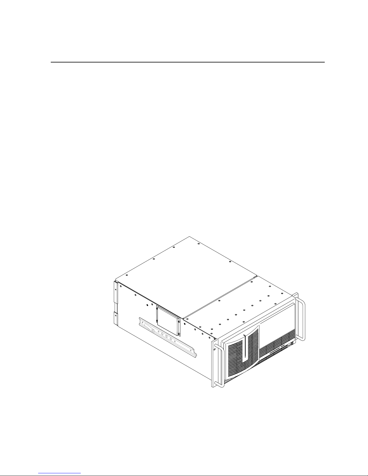
(shown in Figure 1-1) and descriptions of the tasks listed below:
• Installing the vide o file server into an equipment rack.
• Connecting Video and Audio I/O.
• Connecting SCSI devices.
• Connecting Fibre Channel and Ether net.
• Configuring Ethernet IP Address.
• Power On/Off procedures.
Figure 1-1. The Profile Video File Server
9675-10
Page 14

Chapter 1 Introduction
1-2 Profile Video File Server Installation
Related Documentation
Profile Family User Manual
PDR200 Service Manua l
Profile Syst em Sof twa re Re le as e No te s
PDX218 Disk Expansion Chassis Instruction Manual
Windows NT Instruction Manual
Organization of the Manual
The Installation manual is divided into the chapters identif ied and described below.
Chapter 1 - Introduction: This chapter describes the contents of the manual and
provides a brief overview of the Profile Video File Server. It includes configuration
and board location information.
Chapter 2 - Mechanical Installati on: This c hapter describes the physical
installation of the system up to initial power-on.
Chapter 3 - Starting Your Profile System: This chapter consists of procedures to
turn system powe r On and Off, to set up the system, and to verify correct installation
of the Profile Video File Server.
Chapter 4 - Networking Your Profile System: This chapter describes the Ethernet
and Fibre Channel networking use d in the Profile Video File Server, including
connections.
Appendix A - Sp ecificatio ns: This appendi x consists of physical and electrica l
specifications a nd environmental criteria.
Appendix B - Connector P in-outs: This appendix identifies certain connectors and
the signals present and the pins of those connectors.
Page 15

Product Description
Profile Video File Server Installation 1-3
Product Description
The Profile Video File Server is a disk-based video file server with enhanced record
and playback quality, and rapid storage/retrieval c apabilities. In addition to the
advantage of not having to load tape as with VTRs, the Profile Video File Server
occupies less rack space and is fully computer controlled.
The PDR200 provides up to four Motion-JPEG encoders/decoders (CODECs) in a
flexible system which star ts with four base configurations: two are for 2- channel
Profile systems and t wo are for 4- channel Pr ofile syste ms. These base configur ations
can be ordered with analog or digital inputs and outputs. Each configuration is then
tailored, through factory installed options, to meet your site-specific needs . Many
options may be e asily added to your PDR 200 as your needs change and expand. For
information on adding options, contact your Grass Valley Group represe ntative.
A two-channel system (PDR202) is equipped with a single Master Enhanced Disk
Recorder board, which provid es two JPEG codecs, and two SCSI buss es, SCSI A and
SCSI B, although SCSI B may not be a vailable on all models. A four- channel sy stem
(PDR204) adds a Slave Enhanced Disk Recorder, which pr ovides two additional
JPEG codecs and two more SCSI busses (SCSI C and SCSI D).
The PDR300 adds factory-installed MPEG encoders and decoders to the Profile
Video File Server, while retaining all the capabiliti es and optional configurations of
the PDR200. Two MPEG boards, one with one encoder and two decoders, the other
with four decoders, provide many combinations of capabiliti es to meet your needs.
The JPEG codecs on the Master and Slave Enhanced Disk Recorder boards remain
available as resources f or record/p lay channel s or for transcoding cli ps betwee n JPEG
and MPEG.
The PDR400 adds factory-inst alled DVCPRO boards to the Profile Video File S erver,
while retaini ng the same capabili ties and optiona l configura tions of the PDR200. The
DVCPRO boards includes up to six DVCPRO 2 5 codecs arra nged in pair s. Ea ch pair
of DVCPRO 25 codecs may be used a s a single DVCPRO 50 codec. Bec au se of this
paired codec arc h itec tur e, s ome s y stem tim ing rest ri ction s ap ply . These res tri ct ions
are discussed in “DVC PRO System Timing Consider ations” on page 1-17. The JPEG
codecs on the Master and Slave Enhanced Disk Recorder boards remain available as
resources for record/play channels or for transcoding clips between JPEG and
DVCPRO. In some configurations, the operation of one of the JPEG codecs may be
restricted as described in “C onfigurations” on page 1-8.
The Profile Vide o File Server is mounted o n rack slides for installation in a st andard
electronic equip ment rack. All connections to the Profi le Video File Server are on the
rear panel (see Chapter 2, “Mechanical In sta llat io n ”). Also see Appendix A,
“Specifications”, for physic al and electrical spe cifications and environmental crite ria.
Page 16

Chapter 1 Introduction
1-4 Profile Video File Server Installation
Product Features
Record/playback and storage/retrieval applications for the Profile Video File Server
run in the Windows NT
TM
environment. The Windows NT operating software is
loaded on the dedi cated system hard disk, which is also used for application storage .
Control is via an internal Pentium-based CPU board.
Other features incl ude:
• Super-VGA monitor output
• Auto switching 10/100BASE-T Ether net network support
• Control interfaces:
- RS-232 (two rear panel ports)
- RS-422 (eight ports through breakout panel)
- Keyboard and mouse
- Parallel port
• Front panel controls and indic ators.
Page 17
Front Panel Controls and Indicators
Profile Video File Server Installation 1-5
Front Panel Controls and Indicators
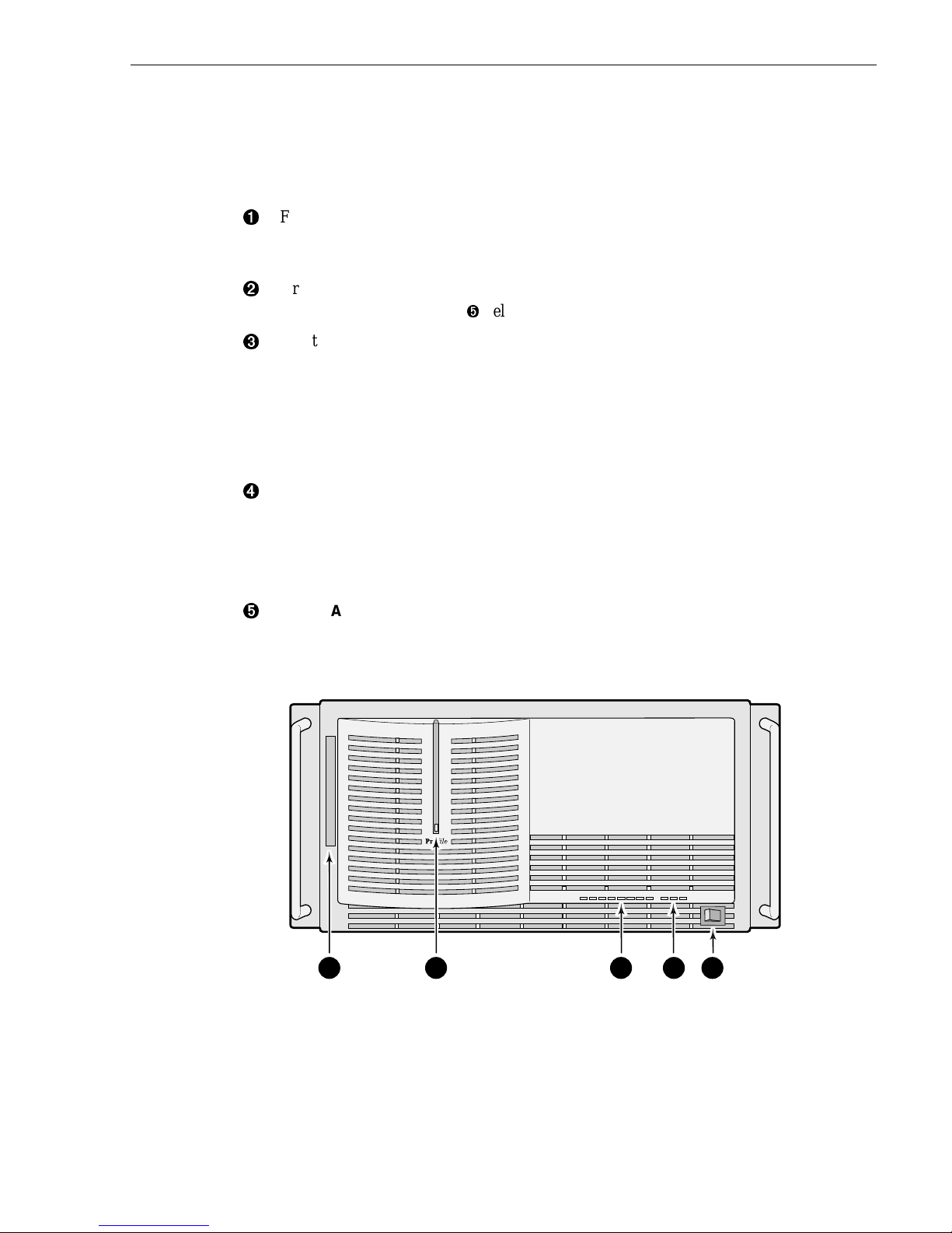
The Profile Video File Server front panel, shown in Figure 1-2, consists of the
controls and indicator s keyed to Figure 1-2 and briefly described below.
Ê
Floppy Disk Drive access for loading operating system software or specific
application soft ware. The drive accepts standard 3-1/2-inch double density
(720KB) or high density (1.44MB) floppy diskettes.
Ë
Green LED indic ator light ed when bot h the p ower s witch on the r ear pane l and the
one on the front panel (see Î below) are On.
Ì
Eight green LED indicators, labeled DISK ACCESS, show disk activity. They are
mapped right to left to the physical loc a tion of each hard disk drive in the chassis
and flash on when activity occurs on the associated disk. A LED should flash on
for every disk ins tal led in the unit . If a LED fai l s to flash on for each disk in the
unit or if a LED remains lit, there may be a problem with the one of the disks. If
you do not have any internal disk storage, which is an option, these LEDs remain
off.
Í
Three red Trouble LED indicators. When lighted they provide warnings of
(from the left):
SYS FAULT (not used)
FAN FAULT (failure of one or more fans)
OVER TEMP (power supply over temperature)
Î
The STANDBY/ON switch provides system On/Off control (the same as pressing
the rear pan el On/Off switch). Both must be On for o peration of the Profile Video
File Server.
Figure 1-2. Profile Video File Server Front Panel
9676-2
1 2 3 4 5
Page 18

Chapter 1 Introduction
1-6 Profile Video File Server Installation
Accessories
There are two types of accessories for the Profile Video File Server: Standard and
Optional. Standard Accessories are those items required to install and operate the
Profile Video File Server. They are shipped with your Profile system. Optional
accessories expand P rof ile Vi deo File Server capabili tie s, si mplif y i nstallati on, or aid
in servicing. Optional accessories are available through Grass Valley Group.
Standar d Acc ess or ie s
A Profile Video File Server shipmen t includes the following items:
• 1 Manual, Profile Family User
• 1 Manual, Installation
• Profile Syst em Sof twa re R elease Notes
• Soft ware Pa ckage which includ es the l atest versi on of Pro fil e Syste m Softwa re an d
an Emergency Repair diskette.
• Windows NT software package
• 1 Keyboard (Grass Valley Group part number 119-4899-XX)
• 1 Mouse (Grass Valley Group part number 119-433 0-XX)
• EMI Suppression Gaskets f or BNC Connectors (Grass Val ley Group part number
016-1448-XX)
• Cable Assemblies, Power (161-0123-00 for US and Japan; 161-0066-09 for
Europe; 161-0066-10 for the United Kingdom; or 161-0066-11 for Australia)
• 1 RS-422 Connector Panel and cable
• 1 Set of rack-mounting slides
• Ethernet cable
Page 19

Optional Accessories
Profile Video File Server Installation 1-7
Optional Accessories
If ordered, Grass Valley Group provide s the optional accessories listed below.
Contact your nearest fie ld office or distributor for more inform ation.
• Ethernet Hub (for Ethernet connections)
• Fibre Channel Hub (for Fibre Channel networking)
• Optical Media Interfa ce Adapter (copper-to-fibe r) for fibre channel networking.
• S-VGA Monitor
• PAC208/216 Analog/Digita l Profile Audio Chassis
• XLR216 or BNC216 Digital Audio Breakout Panel
• PDX218 Disk Drive Expansion Chassis
• 1 SCSI Terminator (011-0166-0 0)
• Eight-connecto r DB25-XLR breakout cable for longitudinal ti me code I/O, 6 ft.
(Grass Valley Group part number 174-3249-XX)
• Eight-connecto r breakout c able, with DB25 conne ctor, 24 ft. (Grass Valley Gr oup
part number 174-3481-XX)
• External CD ROM drive (Grass Valley Group part number PDRFCD)
• Service Manual (070-9675-XX)
Page 20
Chapter 1 Introduction
1-8 Profile Video File Server Installation
Configurations
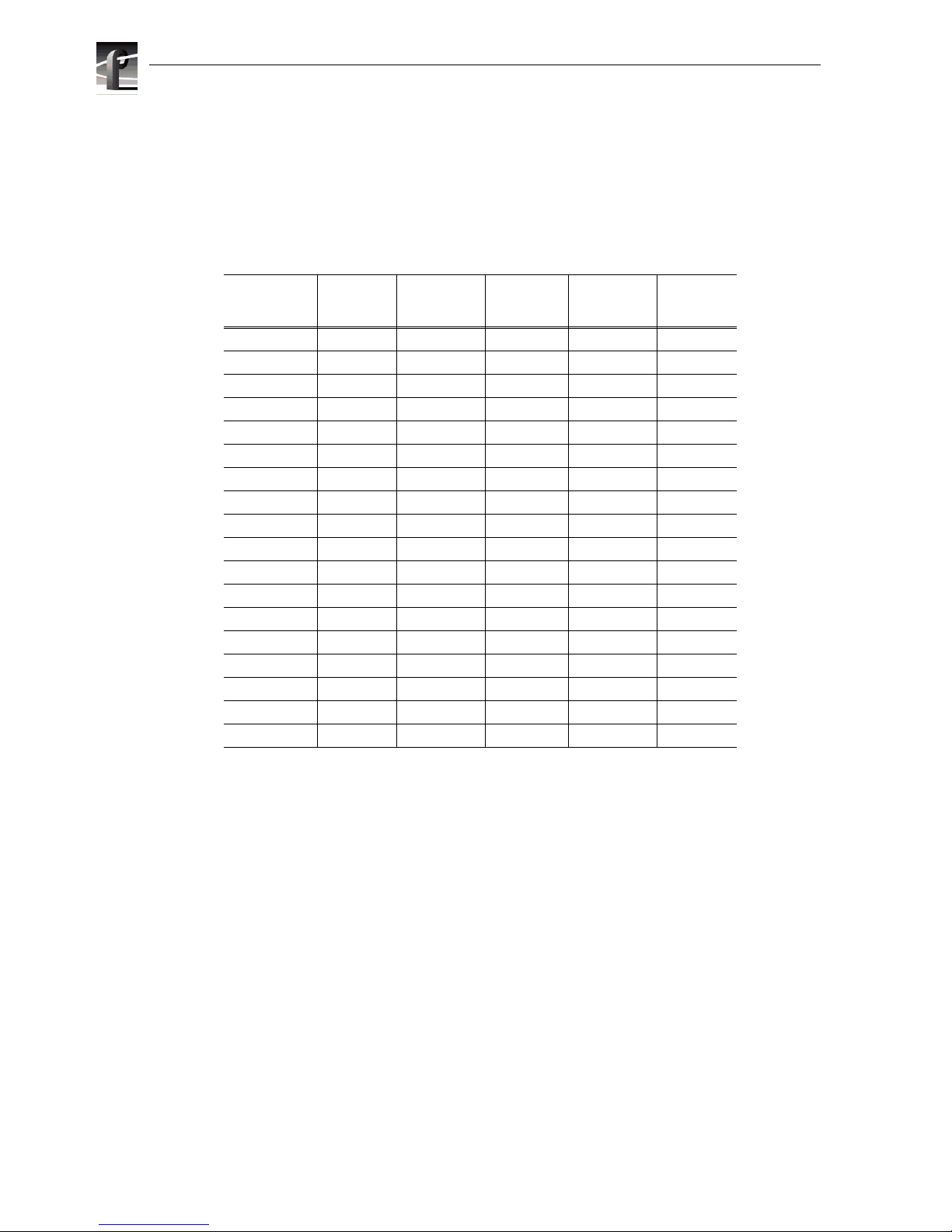
The Profile Vide o File Server is ava ilable in several factory instal led configurations.
Table 1-1 lists the available JPEG codecs, MPEG encoders, MPEG decoders and
DVCPRO2 5 co d ecs t hat are available on each mod el .
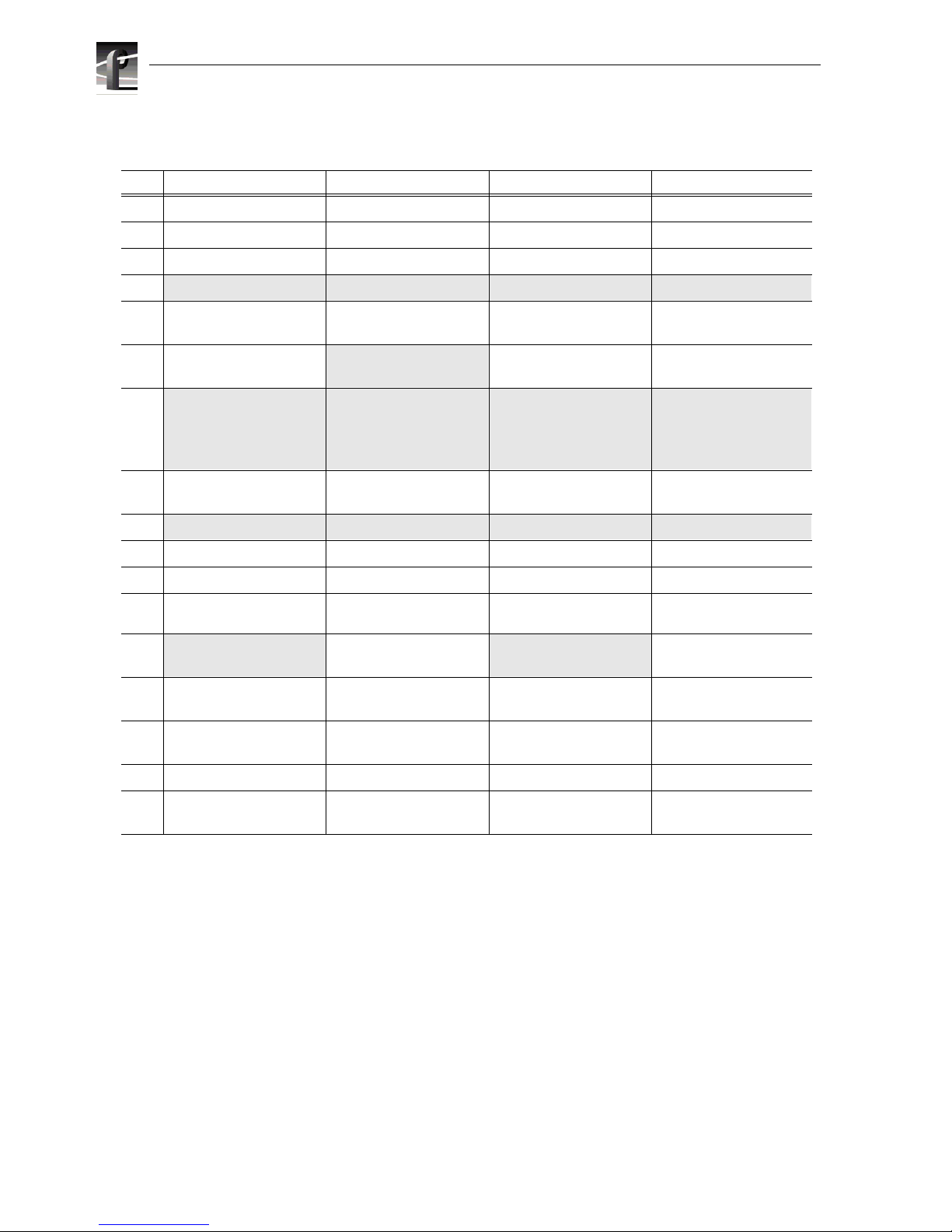
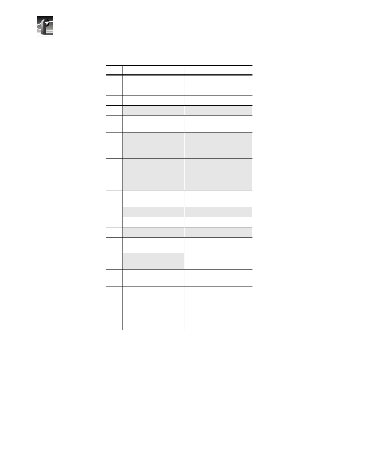
Tables 1-2 through 1-6, on pages 1-9 through 1-13, list the various video I/O
configurations, as well as the locations of all the boards in the system. In the tables,
note that factory inst allable option boards are shaded.
Table 1-1. Profile Video File Server Model Descriptions
Model
Number
Number
of JPEG
CODECs
Number of
MPEG
Encoders
Number of
MPEG
Decoders
Number of
DVCPRO25
CODECs
Video I/O
Type
PDR202A 2 0 0 0 Analog
PDR204A 4 0 0 0 Analog
PDR202D 2 0 0 0 Digital
PDR204D 4 0 0 0 Digital
PDR304A 2 0 4 0 Analog
PDR304D 2 0 4 0 Digital
PDR308A 2 0 8 0 Analog
PDR308D 2 0 8 0 Digital
PDR312A 2
a
a.
4 if Slave Di sk Recorder is installed
120Analog
PDR312D 2
a
120Digital
PDR316A 2
a
160Analog
PDR316D 2
a
160Digital
PDR324A 4 2 4 0 Analog
PDR324D 4 2 4 0 Digital
PDR404A 4
b
b.
If JPEG #2 and DVCPRO25 #4 are used, t hey must both be connected to the same video
input via the internal video crosspoint router, otherwis e, the wrong video input may be
record ed. To avoi d this res tricti on, use on e of the other thr ee JPEG c odecs avai labl e in the
system.
004Analog
PDR404D 4
b
004Digital
PDR406A 4
b
006Analog
PDR406D 4
b
006Digital
Page 21

Configurations
Profile Video File Server Installation 1-9
Table 1-2. PDR202 and PDR204 Factory Standard Configurations with Instal lable Options
Slot PDR202A PDR202D PDR204A PDR204D
J1 System CPU System CPU System CPU System CPU
J2 Parallel Port Parallel Port Parallel Port Parallel Port
J3
J4
System SCSI System SCSI System SCSI System SCSI
J5 Audi o I/O
Digita l A E S/ E BU
Audio I/O
Digital AES/ E B U
Audio I/O
Digital AES/ E B U
Audio I/O
Digital AES/ E B U
J6
Video Mixer Video Mixer Video M ixer Video Mixer
J7
Audio I/O
Digita l A E S/ E BU
Audio I/O
Digital AES/ E B U
Audio I/O
Digital AES/ E B U
Audio I/O
Digital AES/ E B U
J8
Video I/O
Serial D igital Compone nt
Video I/O
Analog Composite
Video I/O
Serial Di gi ta l C ompo nent
Video I/O
Analog Composi te
J9
Fibre Channel Fibre Channel Fibre Channel Fibre Channel
J10 Disk Recor der Master Disk Recorder Master Disk Recorder Master Disk Recorder Master
J11 Disk Recorder Slave Disk Recorder Slave
J12
Video Out
Picture M onitor (Analog)
or
Video Out
Analog Composite
Video Out
Picture Monitor (Analog)
or
Video Out
Analog Composite
Video Out
Picture M onitor ( A nalog)
or
Video Out
Analog Composi te
Video Out
Picture Mo nitor (Analog )
or
Video Out
Analog Composi te
J13
Video In
Analog Component
Video In
Analog Compo nent
Video In
Analog Component
Video In
Analog Component
J14 Video I/O
Analog Composite
Video I/O
Serial Digi tal Compon ent
Video I/O
Analog Composi te
Video I/O
Serial Digital Component
J15 Video I/O
Analog Composi te
Video I/O
Serial Digital Component
J16 Reference / Tim ecode Reference / Timecode Reference / Timecode Reference / Timecode
J17 Remote I/O
RS422
Remote I/O
RS422
Remote I/O
RS422
Remote I/O
RS422
Page 22
Chapter 1 Introduction
1-10 Profile Video File Se rver Installation
Table 1-3. PDR304 and PDR308 Factory Standard Configurations with Installable Options
Slot PDR304A PDR304D PDR 308A PDR308D
J1 System CPU System CPU System CPU System CPU
J2 Parallel Port Parallel Port Parallel Port Parallel Port
J3
J4
System SCSI System SCSI System SCSI System SCSI
J5 A udio I/O
Digital AES/EBU
Audio I/O
Digita l A E S/ E BU
Audio I/O
Digita l A E S /E BU
Audio I/O
Digital AES/EBU
J6 Video Out
Analog Compos ite
Video Out
Picture Monitor (Analog)
Video Out
Analog Composite
Video I/O
Serial Digit al Component
J7
Audio I/O
Digital AES/EBU
or
Video Out
Picture Monitor (Analog)
Audio I/O
Digita l A E S/ E BU
or
Video Out
Picture Monitor (Analog)
Audio I/O
Digita l A E S /E BU
or
Video Out
Picture Mo nitor (Analog)
Audio I/O
Digital AES/EBU
or
Video Out
Picture M onitor (Analog)
J8 MPEG Video
Decoder
MPEG Video
Decoder
MPEG Video
Decoder
MPEG Video
Decoder
J9
Fibre Channel Fibre Channel Fibre Channel Fibre Channel
J10 Disk Recorder Master Disk Recorde r Ma ster Disk Recorder Master Disk Recorder Master
J11
J12 MPEG Video
Decoder
MPEG Video
Decoder
J13
Video I/O
Serial Digit al Component
Video I/O
Serial Digital Component
Video I/O
Serial Digit al Component
J14 Video I/O
Serial Digital Component
Video I/O
Analog Composite
Video I/O
Serial Digit al Component
J15 Video I/O
Serial Digital Component
Video I/O
Analog Composite
Video I/O
Serial Digit al Component
J16 Reference / Timecode Reference / Timecode Reference / Timecode Reference / Timecode
J17 Remote I/ O
RS422
Remote I/O
RS422
Remote I/O
RS422
Remote I/O
RS422
Page 23

Configurations
Profile Video File Server Installation 1-11
Table 1-4. PDR312 and PDR316 Factory Standard Configurations wit h Inst allable Options
Slot PDR312A PDR312D PDR316A PDR316D
J1 System CPU System CPU System CPU System CPU
J2 Parallel Port Parallel Port Parallel Port Parallel Port
J3
J4
System SCSI System SCSI System SCSI System SCSI
J5 Audio I/O
Digital AES/ E B U
Audi o I/ O
Digital AES/ E B U
Audio I/O
Digital AES/EBU
Audio I/O
Digital AES/ E B U
J6
Video Mixer
or
Video Out
Picture Mo nitor (Analog )
Video Mixer
or
Video Out
Picture Mo nitor (Analog)
Video Out
Analog Compos ite
Video Mixer
or
Video Out
Picture Mo nitor (Ana log)
J7
Audio I/O
Digital AES/ E B U
or
Video Out
Picture Mo nitor (Analog )
Audi o I/ O
Digital AES/ E B U
or
Video Out
Picture Mo nitor (Analog)
Audio I/O
Digital AES/EBU
or
Video Out
Picture Monitor (Analog)
Audio I/O
Digital AES/ E B U
or
Video Out
Picture Mo nitor (Ana log)
J8 MPEG Video
Encoder/Decoder
MPEG Video
Encoder/Decoder
MPEG Video
Encoder/Decoder
MPEG Video
Encoder/Decoder
J9
Fibre Chan nel Fibr e Channel Fibre Channel Fibre Channel
J10 Disk Recorder Master Disk Recorder Master Disk Recorder Master Disk Recorder Master
J11
Disk Recorder Slave Disk Recorder Slave Disk Recorder Slave Disk Recorder Slave
J12 MPEG Video
Decoder
MPEG Video
Decoder
J13
Video I/O
Serial Digital Component
Video I/O
Serial Digital Component
Video I/O
Serial Di gi ta l C ompo nen t
J14 Video I/O
Analog Composi te
Video I/O
Serial Digital Component
Video I/O
Analog Compos ite
Video I/O
Serial Di gi ta l C ompo nen t
J15 Video I/O
Serial Di gi ta l C ompo nen t
J16 Reference / Timecode Reference / Timecode Reference / Timecode Reference / Timecode
J17 Remote I/O
RS422
Remote I/O
RS422
Remote I/O
RS422
Remote I/O
RS422
Page 24
Chapter 1 Introduction
1-12 Profile Video File Se rver Installation
Table 1-5. PDR324 Factory Standard Configurations with Instal lable Options
Slot PDR324A PDR324D
J1 System CPU System CPU
J2 Parallel Port Parallel Port
J3
J4
System SCSI System SCSI
J5 Audio I/O
Digita l A E S/ E BU
Audio I/O
Digital AES/EBU
J6
Video Mixer
or
Video Out
Picture Monitor (Analog)
Video Mixer
or
Video Out
Picture Monitor (Analog)
J7
Audio I/O
Digita l A E S/ E BU
or
Video Out
Picture Monitor (Analog)
Audio I/O
Digital AES/EBU
or
Video Out
Picture Monitor (Analog)
J8 MPEG Video
Encoder/Decoder
MPEG Video
Encoder/Decoder
J9
Fibre Channel Fibre Channel
J10 Disk Recorder Master Disk Recorder Master
J11
Disk Recorder Slave Disk Recorder Slave
J12 MPEG Video
Encoder/Decoder
MPEG Video
Encoder/Decoder
J13
Video I/ O
Serial Dig ital Com ponent
J14 Video I/O
Analog Composite
Video I/O
Serial Digital Component
J15 Video I/O
Analog Composite
Video I/O
Serial Digital Component
J16 R eferenc e / Timeco d e Referenc e / Ti m ec ode
J17 Remote I/O
RS422
Remote I/O
RS422
Page 25

Configurations
Profile Video File Server Installation 1-13
Table 1-6. PDR404 Factory Standard Configurations with Installable Options
Slot PDR404A PDR404D PDR406A PDR406D
J1 System CPU System CPU Syst em CPU System CPU
J2 Parallel Port Parallel Port Parallel Port Parallel Port
J3
J4
System SCSI System SCSI System SCSI System SCSI
J5 Audio I/O
Digita l A E S/ E BU
Audio I/O
Digita l A E S/ E BU
Audio I/O
Digita l A ES/EBU
Audio I/O
Digital AES/EBU
J6
Video Mixer
or
Video Out
Picture M onito r (Ana lo g)
Video Mixer
or
Video Out
Picture Monitor (Analog)
Video Mixer
or
Video Out
Picture M onitor (Analog)
Video Mixer
or
Video Out
Picture Monitor (Analog)
J7
Audio I/O
Digita l A E S/ E BU
or
Video Out
Picture M onito r (Ana lo g)
Audio I/O
Digita l A E S/ E BU
or
Video Out
Picture Monitor (Analog)
Audio I/O
Digita l A ES/EBU
or
Video Out
Picture M onitor (Analog)
Audio I/O
Digital AES/EBU
or
Video Out
Picture Monitor (Analog)
J8 Disk Recorder Slave Disk Recorder Slave Disk Recorder Sla v e Disk Recorder Slave
J9
Fibr e C h annel Fi bre Channel Fibre Channel Fibre Channel
J10 Disk Recorder Master Disk Recorder Master Disk Recorder Master Disk Recorder Master
J11 DVCPRO Four-codec DVCPRO Four-codec DVCPRO Four-codec DVCPRO Four-codec
J12 DVCPRO Two-codec DVCPRO Two-codec DVCPRO Two-codec DVCPRO Two-codec
J13
Video I/O
Analog Composite
Video I/ O
Serial Digital Component
Video I/O
Analog Composite
Video I/O
Serial Digital Component
J14 Video I/O
Analog Composite
Video I/ O
Serial Digital Component
Video I/O
Analog Composite
Video I/O
Serial Digital Component
J15 Video I/O
Analog Composite
Video I/ O
Serial Digital Component
Video I/O
Analog Composite
Video I/O
Serial Digital Component
J16 Reference / Timecode Reference / Timecode Reference / Timecode Reference / Timecode
J17 Remote I/O
RS422
Remote I/O
RS422
Remote I/O
RS422
Remote I/O
RS422
Page 26
Chapter 1 Introduction
1-14 Profile Video File Se rver Installation
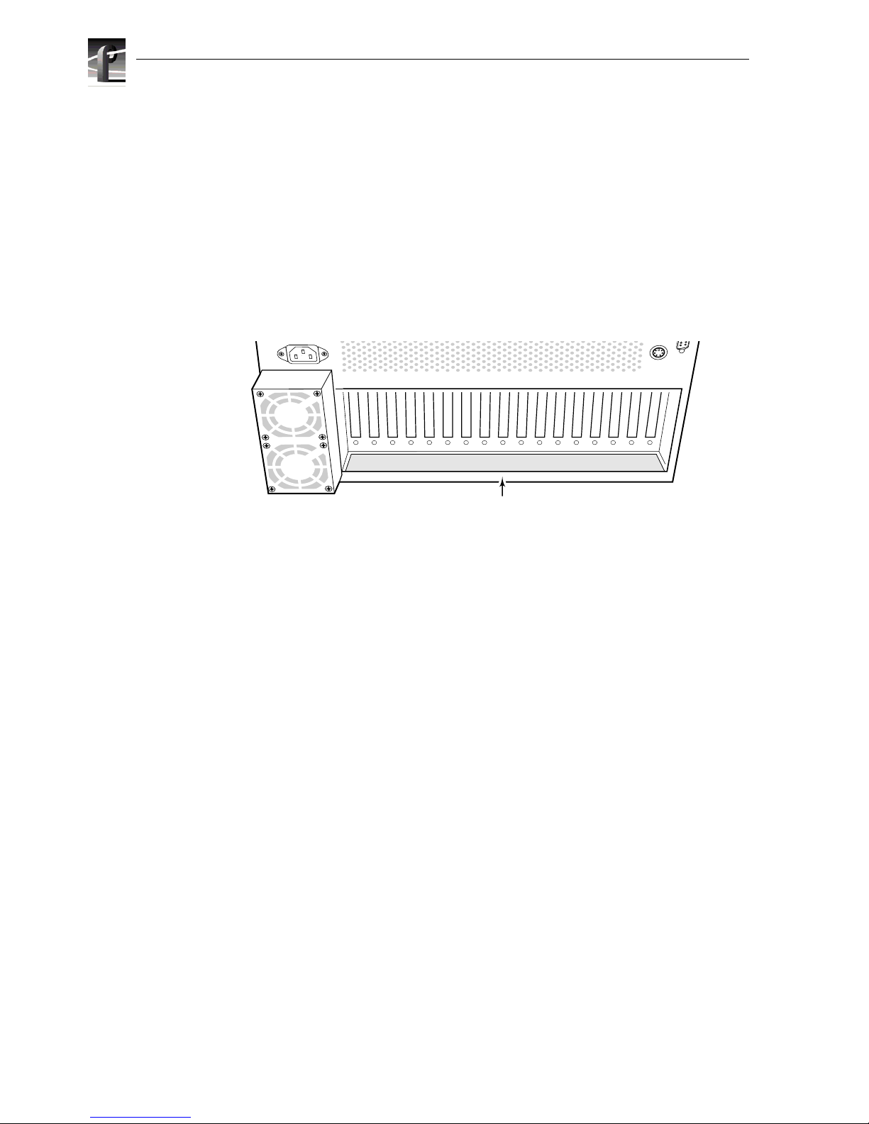
Configuration Labels
You may check/identify your conf iguration, including factory installed options, by
looking at the bottom panel just bel ow the rear panel board connectors. A
configuration label, whic h identifie s the board installe d in the sl ot above t he label, ha s
been attached to assist you in making connections to your Profile system. F igure 1-3
shows the location of the configur ation label.
Figure 1-3. Configuration Labels Locations
9676-26
Labels
Page 27

Maximum Video Data Rates
Profile Video File Server Installation 1-15
Maximum Video Data Rates
This section describes the maximum video data rate available per channel on the
Profile Video Fi le Server whe n all c hannels are in use. The maximum video da ta r ate
per channel depends on the Profile model, the type of storage, and the number of
storage disk drives in the system. The Profile Video File Server can be configured
with either RAID or non-RAID s torage. Refer t o Table 1-7, Table 1-8, and Table 1-9
to determine the maximum video data rates for various Profile models and storage
options.
Table 1-7. Maximum Video Data Rates Per Channel With Non-RAID Storage
Profile Models
with Non-RAID
Storage
Maximum Video Data Rat e Per Chan nel
(When All Channe ls Are In Use )
3 Internal Drives 5 Internal Drives 8 Drives
(Internal or PDX218 )
PDR202 48Mb/s 48Mb/s 48Mb/s
PDR204 not available 48Mb/s 48Mb/s
PDR312 24Mb/s 50Mb/s 50Mb/s
PDR304 24Mb/s 50Mb/s 50Mb/s
PDR324 not available 24Mb/s 24Mb/s
PDR 316 not available 24Mb/s 24Mb/s
PDR308 not available 18Mb/s 24Mb/s
Table 1-8. Maximum Video Data Rates Per Channel With PRS255 RAID Storage Chassis
Profile Models
with the
PRS255 RAID
Storage Chassis
Maximum Video Data Rat e Per Chan nel
(When All Channe ls Are In Use )
5 Drives 10 Drives 15 Drives 20 Drives
PDR202 24Mb/s 48Mb/s 48Mb/s 48Mb/s
PDR204 not allowed 36Mb/s 36Mb/s 48Mb/s
PDR312 24Mb/s 24Mb/s 24Mb/s 50Mb/s
PDR304 24Mb/s 24Mb/s 24Mb/s 24Mb/s
Table 1-9. Maximum Video Data Rates Per Channel With PRS255M RAID Storage Chassis
Profile Models
with the
PRS255M RAID
Storage Chassis
Maximum Video Data Rate Per Channel
(When All Channels Are In Use)
10 Drives 15 Drives 20 Drives
PDR312 50Mb/s 50Mb/s 50Mb/s
PDR304 24Mb/s 50Mb/s 50Mb/s
PDR324 24Mb/s 24Mb/s 24Mb/s
PDR 316 not allowed 24Mb/s 24Mb/s
PDR308 not allowed 18Mb/s 24Mb/s
Page 28
Chapter 1 Introduction
1-16 Profile Video File Se rver Installation
You can select the video data rate the Profile system uses to record the video signal,
unless you are using DVCPRO25 codecs which operate at a fixed 25Mb/s. When
selecting video data rates, be sure not to exceed the total Profile system bandwidth.
Fibre channel trans fers, archive opera tions, and high bandwidth recor ding or playout
may require that you reduce the data rate on other channels or operate fewer channels
at one time. Although playout and recording take priority over other operations,
exceeding your P rofile syst em bandwidth may result in r ecord or pla yback pr oblems.
For information on setting the video data rate in Profile applications software, ref er to
the appropriate sections o f the Profile Family User Manual
Storage Capacity Estimates
The Profile Video File Server stor a ge capacity is determined by the number of disk
drives in the system and the video data rate selected to record the video signal. The
Profile Video File Server can be configured with three, five, or eight int ernal 18GB
disk drives. You c an r efer to Tabl e 1-10 for storage esti mates ba sed on t he number of
disk drives installed and the video data rate. All Profile applications allow you to
select the video data rate used to record the video signal, unless you are using
DVCPRO 25 compression which operates at a fixed 25Mb/s data rate, or
DVCPRO 50 compression which operates at a fixed 50Mb/s data rate. For more
information about set ting the video data rate, refer the appropr iate sections of the
Profile Family User Manual.
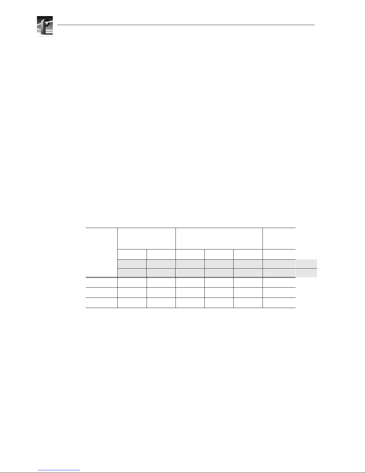
Video storage times are estimates (within 10%) and include 2 audio channels and 1 timecode channel.
Adding 2 more channels of audio adds approximately 1.5 Mb/s to the total data rate .
The Profile Video File Server stor age space can be expanded by adding one or two
PDX 218 Disk Expansion Chassis containing eight 18GB disk drives each. You can
refer to entrie s for eight drive systems in Table 1-10 to determine the storage capacity
of a PDX218 at various video data rates.
NOTE: Storage capacity estimate s for the PRS255 RAID Storage Chassis are
located in the PRS255 RAID Storage Instruction Manual.
Table 1-10. Profil e Video Fi le Ser ver Storage Capacity Estimates
Number of
Internal
Drives
JPEG Factory Preset
Data Rate Targets
MPEG-2 Factory Preset
Data Rate Targets
DVCPRO 25
Data Rate
48Mb/s 24Mb/s 24Mb/s 15Mb/s 8Mb/s 25Mb/s
100KB/fld 50KB/fld 102KB/frm 66KB/frm 37KB/frm 120KB/frm 525/60
120KB/fld 60KB/fld 123KB/frm 78KB/frm 41KB/frm 144KB/frm 625/50
3 disks 2 hrs 4 hrs 4 hrs 6.1 hrs 10.2 hrs
not available
5 disks 3.5 hrs 6.5 hrs 6.5 hrs 10.2 hrs 17 hrs not available
8 disks 5.5 hrs 10.5 hrs 10.5 hrs 16.3 hrs 27.2 hrs 9
Page 29

DVCPRO System Timing Considerations
Profile Video File Server Installation 1-17
DVCPRO System Timing Considerations
The DVCPRO codecs used in Profile systems are actually pairs of codecs. Because of this
paired codec arc h itec ture, some restrict io ns ap pl y to the DVCPRO codec s whic h require the
follow ing sy stem ti ming li mita ti o ns:
1. Y ou must supply a Reference In signal to the Profile system.
2. All video signals that you want to record with a D VCPR O codec must be synchronous with
the Reference In signal.
3. If you want to use the DVCPRO codecs as independent codecs, all of your video inputs
must be auto-timed to the Reference input. In Configuration Manager, select Enable
Auto-Tim ing for each input. You must ensure that each input actually auto-times by
checking that th e Auto-Tim ed indicator in the V ideo Input dia log box is li t. Refer to “Using
the Profile Configuration Manager ” in the Profile Family User Manual for more
information on Auto-Timing.
4. If you are unable to auto-time an input, or if you wish to use the DVCPRO 25 codecs for
BVW Insert/Edit operations, you may only use one of the codecs from each pair,
DVCPRO25 #1, DVCPRO25 #3, and D VCPRO25 #5. Note that the second DVCPRO 25
codec from each pair must not be used.
Page 30

Chapter 1 Introduction
1-18 Profile Video File Se rver Installation
Page 31

Profile Video File Server Installation 2-1
Chapter
2
Mechanical Installation
This chapter describes the mechanical installation of your Profile Video File Server
into an equipment rack and the connection of cables to the rear panel. The chapter
includes examples of connections to peripheral equipment such as the PDX218
storage expansion chassis, the PRS255 RAID Storage chassis. See the appropria te
manuals for ins tal l ation inst ru cti o ns for pe rip he ral eq u ipm en t. T he info rm at io n here
covers:
• Mounting the Profile Video Fil e Server in the rack.
• Mounting the RS-422 Connector Panel.
• Mounting the audio interfac e cha ssis (XLR216, BNC216, or PAC208/216).
• Making Profile Video File Server rear panel cable connections.
• Making other system connections.
Rack Mounting
The equipment for the P rofile Vi deo File S erver syste m installs in a st andard 19-inc h
equipment rac k. Rack slide tracks shipped with the Profile Video File Se rver and the
Profile Audio Chass is allow them to slide in and out without having to remove the m
from the rack. However, if the rack does not already have rack slides installed , or if
the slides are not correctly positioned, you will have to use those shipp ed with the
Profile Video File Server.
When determining the location of the Profile Video File Server in the rack, bear in
mind that the chassis with a full complement of disk drives we ighs appr oximately 70
pounds. Observe the following warnings:
WARNING: To prevent injury, t wo people are requi red to lift the Prof ile Video File
Server. The Profile Video File Server is too heavy for one person to install in the
rack.
WARNING: To prevent serious i njury , in sure that the rack i s anc hored to t he f loor
so that it cannot tip over when the Profile Video File Server is extended out of the
rack.
!
!
Page 32

Chapter 2 Mechanical Installation
2-2 Profile Video File Server Installation
Mounting the Slide Tracks in the Rack
Figure 2-1 shows the components of a right-hand rack slide set. Note that the chassis
sections are already att ached to the Profile Video File Server and PAC208/216. When
mounting rack slides in the equipment rack, bear the following in mind:
• The Profile Video File Server occupies 5 rack units (RUs).
• The PAC208/216 occupies 2 RUs
Figure 2-1. Rack Slide Set for Right Side of Profile Chassis and Rack
Profile Chassis Section
Automatic
Rack
Section
10-32 PHS
10-32 PHS
Flat
Nut
Flat Nut Bar
Intermediate
Stop Latch
Rear
NOTE: Right-hand and left-hand stationary section is designated by the
RH and the LH marked on the rails. Stop latch holes should be towards
Stationary
Page 33

Mounting the Slide Tracks in the Rack
Profile Video File Server Installation 2-3
From Figure 2-2, choose the proper set of rail mounting holes on the rack. Notice that
the hole spacing can vary with the rack type. When mounting the slides in r acks with
EIA spacing, make sure that the slides are attached to the 0.5-inch spaced holes.
Figure 2-2. Spacing Specif ication for Mounting Holes in a Rack
1.250 in
MIL STD 189
“UNIVERSAL” SPACING
0.500 in
0.625 in
1.250 in
1.250 in
0.625 in
Page 34

Chapter 2 Mechanical Installation
2-4 Profile Video File Server Installation
Figure 2-3 and Figure 2-4 show front and rear rail mounting details for both deep and
shallow racks. Mount the rails using the enclosed hardware. Make sure the stationary
sections are horizontally aligned and are level, as well as parallel to each other.
Figure 2-3. Front Rail Mounting Detail
Figure 2-4. Rear Rail Mounting Detail
BAR NUT
(Use if the front rail is not tapped)
BAR NUT
REAR RACK RAIL
PNH
Page 35

Mounting the Profile Video File Server
Profile Video File Server Installation 2-5
Mounting the Profile Video File Server
In addition t o room to make cab le connecti ons, the Profil e Video File Serve r require s
six inches (15.25 cm) of clearance behind the rear panel for connectors and cable
bends. Insure adequate air flow around the chassis to provide suffic ient cooling.
(Operating ambient temperature will affect the amount of air circulation required to
keep the Profile Video File Serve r with in its temperature limitations.)
1. Pull the slide-out track section to the fully extended position. See Figure 2-5.
WARNING: To prevent injury, t wo people are requi red to lift the Prof ile Video File
Server. It is too heavy for one person to install in the rack.
WARNING: To prevent serious i njury , in sure that the rack i s anc hored to t he f loor
so that it cannot tip over when the Profile Video File Server is extended out of the
rack.
2. Insert the ends of the chassis sections into the slide-out se ctions.
3. Push the chassis toward the rack unti l the chassis s ections lock into the int ermediate
sections.
4. Press the stop latches in the intermediate sections an d push the chassis toward the
rack until the latches sna p into their holes.
Figure 2-5. Rack Slide Stop Latc h
5. Again, press the stop latches and push the cabinet fully into the rack.
6. Insert and tighten the front panel retaining screws.
!
!
Stop Latch
Page 36

Chapter 2 Mechanical Installation
2-6 Profile Video File Server Installation
Maki ng Rack Slide Adjustments
After install ation, binding may occu r if the slide tracks are not properly adjusted. To
adjust the tracks:
1. Slide the chassis out approximately 10 inches.
2. Slightly loosen the mounting screws holding the tr acks to the f ront of the rail s and
allow the tracks to seek an unbound posit ion.
3. Tighten the mounting screws and check the tra cks for sm ooth operat ion by sli ding
the chassis in and out of the rack several times.
4. Tighten the front panel retaining scr ews once the cabinet is in place within th e rack
to complete the installation.
Mounting Panels and Audio Chassi s
Refer to the information that f ollows when mounting panels and audio chassis:
• The RS-422 Connector Panel is 1 RU high with the mounting holes space d 1.250
inches (3.17 5 cm ) apart .
• The XLR 216 is 2 RUs high with holes spaced 3.000 inches (7.62 cm) apart.
• The BNC216 is 1 RU high with holes spaced 3.000 inches (7.62 cm) apart.
• The PAC208 and PAC216 Audio Breakout panels are 2 RUs high with holes
spaced 3.000 inches (7.62 cm) apart.
The RS-422, XLR216 and BNC216 panels mount at the back of the rack with four
pan head screws. Ensure that there is ro om to make cable connections and mount in
any order which allows connection to the PRO Series Video Disk Recorder.
Page 37

Making Rear Panel Connections
Profile Video File Server Installation 2-7
Making Rear Panel Connections
Because of the flexible c onfigurations of the Profile Video File Server, not all of the
rear panel connections de scribed here may apply to your Profile system. The
connections are described as though all factory installable options were in fact
installed. As yo u go thr ough these instr uctions, simply ignor e a board you do not have
installed. Note that any rear panel sl ot which does not h ave a board insta lled will have
a blank cover over the rear panel slot.
NOTE: Insure that power switches of all equipmen t to be installed are in the
Off (O) positions.
To insure complianc e with EMI st andards, all B NC cable connec tions requi re tha t an
EMI suppression gasket be attac hed as shown in Figure 2-6. Your Profile system
shipment included a set of gaskets.
Figure 2-6. BNC Connection With EMI Gasket
9040-1
Page 38

Chapter 2 Mechanical Installation
2-8 Profile Video File Server Installation
Connecting the Mouse and Keyboard
The Profile system mouse and keyboard con nector s are located on the rear panel as
shown in Figure 2-7.
Connect the mouse and keyboard as shown in Figure 2-7.
Figure 2-7. Mouse, Keyboard, and S- VGA Monitor Connections
Connecting the Monitor
The S-VGA monitor c onnector is locate d on the Syste m CPU boa rd lo cated i n sl ot J 1.
Connect the S-VGA Monitor cable to the 15-pin conn ector as shown in Figure 2-7.
J1
J13
J14 J6J7
J4 J3 J2
J5
J12
J11 J9
J8
J10
9676-68
System
CPU
Mouse
Keyboard
Monitor
Parallel
Port
Page 39

Connecting the Reference Genlock
Profile Video File Server Installation 2-9
Connecting the Referen ce Genlock
The Profile Video File Server pro vides a Reference Genlock board, standard on all
configuration s, with two BNC connec tors and a 25-pin DIN connector. The BNC
connectors form a bridging, high impedance loop-th rough for the analog black burst
house reference si gnal. Thi s sig nal is used to sync hronize t he syste m video clock a nd
provide frame referenc e. The 25-pin DIN provides Longitudinal Time Code
interfaces, four in and four out. See Figure 2-8.
Figure 2-8. Reference Genlock Cable Connections
To make cable connections to the Reference Genlock board, refer to Figure 2-8 and:
1. Attach the optional Longitudinal Time Code breakout cable (Figure 2-9) to the
25-pin DIN connector.
Figure 2-9. Break out Cable
2. Place EMI gaskets on the BNC connectors as shown in Figure 2-6, page 2-7.
3. Attach the House Reference (Black Burst) BNC cable to the lower BNC connector.
4. Attach a 75Ω End-line Terminator to the upper BNC connector.
J17 J13J16
J15 J14 J6J7J4J5
J12
J11 J9
J8
J10
9676-9
Reference Analog Video
LTC Breakout Cable
House Reference
75Ω Terminator
9040-5
Page 40

Chapter 2 Mechanical Installation
2-10 Profile Video File Se rver Installation
Connecting V ide o
The Profile Video File Server supports S erial Digita l I/O, Analog Composite I/O, and
Analog Component Inputs . The v ideo conne ctions yo u make depen ds o n your Pro file
Video File Server configuration.
Connecting Serial Digital Video
The Profile Video File Server allows Serial Digital Video I/O board installati ons for
two channels of serial digital input and output per board. Figure 2-10 shows serial
digital cable connect ions for a typ ical loc ation, slot J14. Refer to the rear panel la bels
or Tables 1- 2 through 1-6 in Chapter 1, pages 1- 9 through 1-13, to determine the slot
location of this board in your system.
1. Place EMI gaskets on the four BNC connectors as shown in Figure 2-6, page 2-7.
2. Attach two BNC cables from seria l digit al sources to t he IN A a nd IN B connect ors.
3. Attach two BNC cables to serial digital sources to the OUT A and OUT B
connectors.
Figure 2-10. Serial Dig ital I/O Cable Connections
J1
J17 J13J16
J15 J14 J6J7
J4 J3 J2
J5
J12
J11 J9
J8
J10
9676-56
Video I/O Serial Digital Component
In B
In A
Out A
Out B
Page 41

Connecting Video
Profile Video File Server Installation 2-11
Connecting Analog Composite Video I/O
The Profile Vide o File Server may include one or more an Analog Composite Video
In/Output boards. Figur e 2-11 shows analog composite video cable conne ctions for a
typical locatio n, slot J14. Refer to the rear panel labels or Tables 1-2 through 1-6 in
Chapter 1, pages 1-9 through 1-13, to determine the slot location of thi s board in your
system.
The Analog Composite I/O board accepts two composite analog video inputs, and
provides two composite analog vide o outputs. The board is also equipped with an
S-Video connector, which allows video input to the Profile system directly from a
source such as a vi deo cassette re corder. However, the S-Video devi ce takes the plac e
of one of the input s (eithe r In A or I n B). The board pr ovides ti me base cor rectio n for
any one input. If the Analog Composite Video I/O board is installed, refer to
Figure 2-11 for an example and:
1. Place an EMI gasket on the BNC connectors being used as shown in Figure 2-6,
page 2-7.
2. Connect analog composite input and output cables to the Analog Composite I/O
board. See Figure 2-11 for an example.
Figure 2-11. Analog Composite I /O Cabl e Connecti ons
J1
J17 J13J16
J15 J14 J6J7
J4 J3 J2
J5
J12
J11 J9
J8
J10
9676-58
Video I/O
Analog Composite
S-video In
In B
Out A
Out B
In A
Page 42

Chapter 2 Mechanical Installation
2-12 Profile Video File Se rver Installation
Connecting Analog Composite Monitor
The Profile Video File Server may include an Analog Composite Monitor board
which provides four channels of analog composite video output with time code
burn-in and text overlay. With this board you can simultaneously displ ay independent
time code of each playback channel on a picture monitor display. Each channel also
provides text overlay for source identification.
Figure 2-12 shows composite monitor cable conne ctions for a typical location, slot
J12. Refer to the rear panel labels or Tables 1-2 through 1-6 in Chapter 1, pages 1-9
through 1-13, to determine the slot location of this board in your system.
1. Place an EMI gasket on each BNC connector as shown in Figure 2-6, page 2-7.
2. Attach four BNC cables for composite video outputs to the OUT A, OUT B,
OUT C, and OUT D connectors.
Figure 2-12. Analog Composite Monitor Cable Connections
J1
J17 J13J16
J15 J14 J6J7
J4 J3 J2
J5
J12
J11 J9
J8
J10
9676-60
Out B
Out A
Out C
Out D
Video Out
Analog Composite (Monitor)
Page 43

Connecting Video
Profile Video File Server Installation 2-13
Connecting Analog Composite Video Out
The Profile Video File Server may include an Analog Composite Video Out board
which provides u p to four channels of a nalog composit e video ou tput. The b oard also
has a Monitor D connector which is the Out D video with time code burn-in available .
Figure 2-13 shows analog composite video out cable co nnections for a typical
location, slot J6. Refe r to the r ear panel la bels or Tabl es 1- 2 thr ough 1 -6 in Chapter 1,
pages 1-9 through 1-13, to determine the slot location of this board in your system.
1. Place an EMI gasket on each BNC connector as shown in Figure 2-6, page 2-7.
2. Attach four BNC cables for composite video outputs to the OUT A, OUT B,
OUT C, and OUT D connectors.
3. Attach a BNC cable for the Out D output with time code burned-in to the
Monitor D connector (optional)
Figure 2-13. Analog Composite Out Cable Connections
J1
J17 J13J16
J15 J14 J6J7
J4 J3 J2
J5
J12
J11 J9
J8
J10
9676-21
Video Out
Analog Composite
Out B
Out A
Out C
Out D
Monitor D
Page 44

Chapter 2 Mechanical Installation
2-14 Profile Video File Se rver Installation
Connecting Component Analog Video
The Profile Video File Server may include an Component Analog Video In board
which accepts a single source of component analog video input.
Figure 2-14 shows component analog video in cable connections for a typical
location, slot J13. Refer to t he re ar panel labels or Tables 1-2 through 1 -6 in Chapter
1, pages 1-9 throug h 1- 13, to de termine th e slot l ocati on of thi s boa rd in y our syste m.
To make connections to th e Analog Component Vid eo In board , refer to the example
in Figure 2-14 and:
1. Place an EMI gasket on the three BNC connectors as shown in Figure 2-6,
page 2-7.
2. Attach three BNC cables from an appropriate component analog video sourc e to
the connectors.
Figure 2-14. Analog Component Video In Cable Connections
J1
J17 J13J16
J15 J14 J6J7
J4 J3 J2
J5
J12
J11 J9
J8
J10
9676-57
Video In
Analog Component
Y/G
B -Y/B
R -Y/R
Page 45

Connecting Audio
Profile Video File Server Installation 2-15
Connecting Audio
Your Profile Video File Server can have one or two Audio I/O boards inst alled. All uni ts have
at least one Audio I/O boar d, called Audio Signal Processor Board ( or ASPB), whi ch provides
16 channels of audio I/O. A second ASPB can be installed, adding 16 more channels for a total
of 32 channels of audio I/O.
If you have two Audio I/O boards installed, the first one (or ASPB1) resides in the lowest
numbered board slot and is labelle d “AUDIO I/O IN/OUT CH 1-16”. The second ASPB (or
ASPB2), if installed, is in the higher numbered board slot and is labelled “AUDIO I/O IN
OUT CH 17-32”. Refer to the rear panel labels or Table s 1-2 through 1-6 in Chapter 1, pages
1-9 through 1-13, to determine the slot location of these boards in your system.
The Audio Signal Processor Board (ASPB) can be configured to operate with analog, AES/
EBU digital, and digital embedded (SMPTE 272M Level A) audio. If you are using only
embedded audio, no interface chassis is required.
An interface chassis is required for Analog and AES/EBU Audio. Table 2-1 contains a
summary of interface chassis avail abl e.
NOTE:
- Interface chassis must be connected to both ASPBs for operation with 32 channels
of analog or AES/EBU digital audio.
- To determine if the PAC200 Analog Audio Chassis is a PAC208 or PAC216, look
at the identificati on tag toward the rear on the left side of the chassis.
Table 2-1. Audio Interface Chassis Summary
PAC200 Chassis
Models
Number of
Analog
Audio
Channels
Number of
AES/EBU
Audio
Channels
Comments
PAC208 8
(Ch 1 to 8)8(Ch 9 to 16 )
ASPB audio channels 1 to 8 are always
assigned to PAC208 analog channels 1 to 8.
ASPB au dio chann e ls 9 to 16 are al w ay s
assigned to PAC208 AES/EBU digital
channels 9 to 16.
PAC216
(includes PACX LR
breakout chassis)
16 16 The 16 ASPB audio channe ls ar e divi ded i nto
four audio grou ps (4 ch annels each). You can
assign the inp ut fo r ea ch aud io g ro up to e it her
the analog or digital inputs of the PAC216.
For exampl e, the input to ASPB ch annels 1 t o
4 can be assigned to analog input chan nels 1 to
4 or digital input channels 1 to 4 on the
PAC216. The ASPB output channels 1 to 16
are alwa ys as si gne d to bot h anal og an d d igit al
output channels 1 to 16 on the PAC216.
XLR216 none 16 Provides digital audio interface using XLR
connectors.
BNC216 none 16 Provides digital audio interface using BNC
connectors.
Page 46

Chapter 2 Mechanical Installation
2-16 Profile Video File Se rver Installation
The 16 channels supporte d by the ASPB are divid ed into four audio gr oups with fou r
audio channels in each gr oup. The fir st group consist s of channel s 1 to 4. The second
group consists of channel s 5 to 8, and so on up to the fourth group.
Audio channels are typically assigned by groups to video channels. However, some
Profile applic ations allow you to assign individual audio channels to video channels,
provided you select the appr opriate audio clock reference. See the Configuration
Manager chapter of the Profile Family User Manua l for more information a bout audio
channel assignments.
See Appendix A, Table A-11 and Table A-12, for audio specifications.
Connecting 16 Channels AES/EBU Digital Audio (XLR216 or BNC216)
Figure 2-15 shows ASPB connection to eithe r an XLR216 audio panel or a BNC216
Audio panel for up to 16 channels (eight pai rs) of AES/EBU digital only audio.
AES/EBU digital au dio sources ar e then connecte d to the XLR or BNC connectors on
the panel.
Note the following on the XLR216 Audio Panel:
• Each pair of digital audio channels (1/2, 3/4... 15/16) has an In (top row on the
panel) and an Out (bottom row).
• Connectors labelled “spares” are not avail abl e (n ot con nect ed ) .
• The AES REF connector provides both a clock fre quency and a framing alignment
reference, generally from a master sync generator, to the incoming digital audio.
• The AES/EBU MONITOR connector allows monitoring of one of the eight pairs
of digital audio channel s selected through software (see the Profile Family User
Manual). This is a digital audio output.
Note the following on the BNC216 Audio Panel:
• Each pair of digit al audio cha nnels (1/2, 3/4 , etc.) has a n In and an Out, side by side
across the panel.
• The AES REF connector provides both a clock fre quency and a framing alignment
reference, generally from a master sync generator, to the incoming digital audio.
• The MON OUT connector allows monitoring of one of the eight pair s of digi tal
audio channels selecte d through software (see the Profile Family User Manual).
This is a digital audio output.
Page 47

Connecting Audio
Profile Video File Server Installation 2-17
Figure 2-15. ASPB Connections for 16 Channels of AES/EBU Digital Audio
J1
J17 J13J16
J15 J14 J6J7
J4 J3 J2
J5
J12
J11 J9
J8
J10
PROFILE
XLR216
Audio
Panel
OR
9676-49
BNC216
Audio
Panel
In
Out
In
Out
. . .
1/2
Digital (AES/EBU)
Channels
1-16
AES
Ref
Spares
AES/EBU
Monitor
Mon
Out
ASPB
Digital (AES/EBU)
Channels
1-16
AES
Ref
Page 48

Chapter 2 Mechanical Installation
2-18 Profile Video File Se rver Installation
Connecting 32 Channels AES/EBU Digital Audio (XLR216 or BNC216)
Figure 2-16 shows AES/EBU digital audio interface connections for a 32 audio
channel Profil e Video File Server. The 32 channel Profile system has two Audio I/O
boards: ASPB1 and ASPB2. ASPB1 is in the lowe r numbere d slot, and ASPB2 is in
the higher numbered slot. Refer to the rear panel labels or Tables 1-2 through 1-6 in
Chapter 1, pages 1-9 through 1-13, to determine the slot location of these boards in
your system.
The 32 channel AES/EBU digital audio confi guration uses two XLR216 Audio
Panels or two BNC216 Audio Panels for up to 32 channels (sixteen pairs) of AES/
EBU digital audio. AES/EB U digi tal audio sour ce s are then c onnect ed to the XLR or
BNC connectors on the panel.
Note the following on each XLR216 Audio Panel:
• The XLR216 connected to ASPB1 supports channels 1-16.
• The XLR216 connected to ASPB2 supports channels 17-32.
• Each pair of digital audio channels has an In (top row on the panel) and an Out
(bottom row).
• Connectors labelled “spares” are not avail abl e (n ot con nect ed ) .
• The AES REF connector on each XLR216 provides both a clock frequency and a
framing alignment reference, generally from a master sync generator, to the
incoming digital audi o.
• The AES/EBU MONITOR connector on each XLR216 allows monitoring of one
of the eight pairs of digital audio channels selected through software (see the
Profile Family User Manual). This is a digital audio output.
Note the following on each BNC216 Audio Panel:
• The BNC216 connected to ASPB1 supports channels 1-16.
• The BNC216 connected to ASPB2 supports channels 17-32.
• Each pair of digital audio channels has an In and an Out, side by side across the
panel.
• The AES REF connector provides both a clock fre quency and a framing alignment
reference, generally from a master sync generator, to the incoming digital audio.
• The MON OUT connector allows monitoring of one of the eight pair s of digi tal
audio channels selecte d through software (see the Profile Family User Manual).
This is a digital audio output.
Page 49

Connecting Audio
Profile Video File Server Installation 2-19
Figure 2-16. ASPB Connections for 32 Channels of AES/EBU Digital Audio
J1
J17 J13J16
J15 J14 J6J7
J4 J3 J2
J5
J12
J11 J9
J8
J10
9676-55
ASPB2
(Channels 17-32)
ASPB1
(Channels 1-16)
PROFILE
ASPB1
XLR216
Breakout Panel
ASPB2
XLR216
Breakout Panel
ASPB1
BNC216
Breakout Panel
ASPB2
BNC216
Breakout Panel
In
Out
Digital (AES/EBU)
Channels
1-16
AES
Ref
Spares
AES/EBU
Monitor
PROFILE
In
Out
Digital (AES/EBU)
Channels
17-32
AES
Ref
Spares
AES/EBU
Monitor
In
Out
. . .
1/2
Mon
Out
Digital (AES/EBU)
Channels
17-32
AES
Ref
To ASPB1
Mon
Out
Digital (AES/EBU)
Channels
1-16
AES
Ref
To ASPB2
OR
Page 50

Chapter 2 Mechanical Installation
2-20 Profile Video File Se rver Installation
Connecting 8 Analog and 8 Digital Channels (PAC208)
Figure 2-17 shows analog/digital audio connections for a 16 audio channel Profile
Video File Server using the PAC208 version of the PAC200 Profile Audio Chassis.
The PAC208 chassis all ows you to connect eight analog and eight di gita l (four pair s)
audio I/Os to the Profile Video File Server. ASPB audio channels 1 to 8 are always
assigned to PAC208 analog channels 1 to 8. ASPB a udio channe ls 9 to 16 are always
assigned to PAC208 AES/EBU digital channels 9 to 16.
When used in this configurati on, the PAC200 is labelled PAC208 on the left side
panel at the rear of the panel.
NOTE: When using analog audi o, you must u se Conf iguratio n Manager t o enable
analog audio inputs and to unmute analog audio outputs. See the Profile Family
User Manual for Configuration Manager information.
On the PAC200 (PAC208):
• Connections are for analog audio channels 1-8, each with an In and Out.
• Connections are for four pairs of digital audio channels: 9/10, 11/12, 13/14, and
15/16, where each pair has an In and Out.
• The AES REF IN connector provides both a clock frequency and a framing
alignment referenc e, generally from a master sync generator, to the incoming
digital audio.
• The MONITOR LEFT/RIGHT connectors allow monitoring of one pair of audio
selected through so ftware (see the Profile Family User Manual) . This is an ana log
output.
Page 51

Connecting Audio
Profile Video File Server Installation 2-21
Figure 2-17. ASPB Connections for 8 Analog and 8 Digital Audio Channels
J1
J17 J13J16
J15 J14 J6J7
J4 J3 J2
J5
J12
J11 J9
J8
J10
9676-50
Analog
Channels
1-8
In
Out
PAC208
Audio
Chassis
Digital (AES/EBU)
Channels
9-16
AES
Ref Monitor
ASPB
Page 52

Chapter 2 Mechanical Installation
2-22 Profile Video File Se rver Installation
Connecting 16 Analog/Digital Channels (PAC216)
Figure 2-18 shows analog/digital audio connections for a 16 audio channel Profile
Video File Server using the PAC216 version of the PAC200 Profile Audio Chassis.
This Profile system has one ASPB (Audio Signal Processor Board) which provides
16 channels of audio I/O. The PAC216 chassis and the PACXLR Audio Breakout
Panel, allows you to connect up to 16 analog audio I/Os and 16 digital audio I/Os
(eight pairs) to the Profile Video File Server.
The 16 ASPB audio channels are divided into four audio groups of four channels
each. You can assign the input for each ASPB audio group to either the analog or
digital input c hannels of the PAC216. For example, the input to ASPB channels 1 to
4 can be assigned to analog input channels 1 to 4 or digital input channels 1 to 4 on
the PAC216. The four ASPB audio groups are always assigned to both analog and
digital output channels on the PAC216.
When used in this configurati on, the PAC200 is labelled PAC216 on the left side
panel at the rear of the panel.
NOTE: When using analog audi o, you must u se Conf iguratio n Manager t o enable
analog audio inputs and to unmute analog audio outputs. See the Profile Family
User Manual for Configuration Manager information.
On the PAC200 (PAC 216):
• Connections are for analog audio channels 1-8, each with an In and Out.
• Connections are for four pairs of digital audio channels: 9/10, 11/12, 13/14, and
15/16, where each pair has an In and Out.
• The AES REF IN connector provides both a clock frequency and a framing
alignment referenc e, generally from a master sync generator, to the incoming
digital audio.
• The MONITOR LEFT/RIGHT connectors allow monitoring of one pair of audio
selected through so ftware (see the Profile Family User Manual) . This is an ana log
output.
On the PACXLR Breakout Panel:
• Connections are for analo g audio channels 9-16, each with an In and Out.
• Connections are for four pairs of digital a udio channels: 1/2, 3/4, 5/6, and 7/8 where
each pair has an In and Out.
Page 53

Connecting Audio
Profile Video File Server Installation 2-23
Figure 2-18. ASPB Connections for 16 Analog and 16 Digital Audio Channels
J1
J17 J13J16
J15 J14 J6J7
J4 J3 J2
J5
J12
J11 J9
J8
J10
9676-51
Analog
Channels
1-8
In
Out
In
Out
PROFILE
PAC216
Audio
Chassis
PACXLR
Audio
Breakout
Panel
Digital (AES/EBU)
Channels
9-16
AES
Ref Monitor
Analog
Channels
9-16
Digital (AES/EBU)
Channels
1-8
AES
Ref
Monitor
ASPB
Page 54

Chapter 2 Mechanical Installation
2-24 Profile Video File Se rver Installation
Connecting 32 Analog/Digital Channels (PAC216)
Figure 2-19 shows analog/digit al interfac e connections for a 32 audio channe l Profile
Video File Server. The 32 channel Profile syste m has two Audio I/O boards: ASPB1
and ASPB2. ASPB1 is in the lower numbered slot, and ASPB2 is in the higher
numbered slot. Refer to the rear panel labels or Table s 1-2 through 1-6 in Chapter 1,
pages 1-9 thr ough 1-13, t o determine the slot location of these boards in your system.
The 32 channel analog/digi tal audio configuration uses two PAC216 Profile Audio
Chassis. Each PAC216 chassis and PACXLR Audio Breakout Panel all ows you to
connect up to 16 analog audio I/Os and 16 digital audio I/Os for a total of 32 analog
audio and 32 of digital audio I/Os.
The 16 audio channels on each ASPB are divided into four audio groups of four
channels each. You can assign the input for each ASPB audio group to either the
analog or digital input channels of the PAC216. For example, the input to ASPB1
channels 1 to 4 can be assigned to analog input channels 1 to 4 or digital input
channels 1 to 4 on the PAC216. The four ASPB audio groups are always assigned to
both analog and digital outp ut channels on the PAC216.
When used in this configurati on, the PAC200s are labelled PAC216 on the left side
panel at the rear of the panel.
NOTE: When using analog audi o, you must u se Conf iguratio n Manager t o enable
analog audio inputs and to unmute analog audio outputs. See the Profile Family
User Manual for Configuration Manager information.
On the PAC200 (PAC216) connected to ASPB1:
• Connections on the chas sis are provided for analog audio c hannels 1-8, each with
an In and Out.
• Connections on the chassis are provide d for four pairs of digital audio channels:
9/10, 11/12, 13/14, and 15/16, whe re each pair has an In and Out.
• Connections on the PACXLR Audio Breakout Panel are provided for anal og audio
channels 9-16, each with an In and Out.
• Connections on the PACXLR Audio Breakout Panel are provide d for four pairs of
digital audio channels: 1/2, 3/4, 5/6, and 7/8 where each pair has an In and Out.
• The AES REF IN connector provides both a clock frequency and a framing
alignment referenc e, generally from a master sync generator, to the incoming
digital audio.
• The MONITOR LEFT/RIGHT connectors allow monitoring of one pair of audio
selected through so ftware (see the Profile Family User Manual) . This is an ana log
audio output.
On the PAC200 (PAC 216) connected to ASPB2:
• Connections on the chassis are provided for analog audio channels 17-24, each
with an In and Out.
• Connections on the chassis are provided for f our pairs of digital audio channels: 17/
18, 19/20, 21/22, and 23/24 where each pair has an In and Out.
Page 55

Connecting Audio
Profile Video File Server Installation 2-25
• Connections on the PACXLR Audio Breakout Panel are provide for analog audio
channels 25-32, each with an In and Out.
• Connections on the PACXLR Audio Breakout Panel are for four pairs of digita l
audio channels: 25/26, 27/28, 29/30, and 31/32 where each pair has an In and Out.
• The AES REF IN connector provides both a clock frequency and a framing
alignment referenc e, generally from a master sync generator, to the incoming
digital audio.
• The MONITOR LEFT/RIGHT connectors allow monitoring of one pair of audio
selected through so ftware (see the Profile Family User Manual) . This is an ana log
output.
Figure 2-19. ASPB Connections for 32 Analog and 32 Digital Audio Channels
J1
J17 J13J16
J15 J14 J6J7
J4 J3 J2
J5
J12
J11 J9
J8
J10
9676-54
Analog
Channels
1-8
In
Out
In
Out
PROFILE
ASPB1
PAC200 Audio Chassis
(Back)
ASPB1
PAC XLR Breakout
Panel (Front)
ASPB2
PAC200 Audio Chassis
(Back)
ASPB2
PAC XLR Breakout
Panel (Front)
Digital (AES/EBU)
Channels
9-16
AES
Ref Monitor
Analog
Channels
9-16
Digital (AES/EBU)
Channels
1-8
Analog
Channels
17-24
In
Out
In
Out
PROFILE
Digital (AES/EBU)
Channels
25-32
AES
Ref Monitor
Analog
Channels
25-32
Digital (AES/EBU)
Channels
17-24
Spares
Spares
PAC
Breakout
PAC
Breakout
Main
Audio I/O
PAC
Breakout
PAC
Breakout
Main
Audio I/O
ASPB2
(Channels 17-32)
ASPB1
(Channels 1-16)
Page 56

Chapter 2 Mechanical Installation
2-26 Profile Video File Se rver Installation
Connecting SCSI Devices
The Profile Video File Server has a number of connectors for at taching SCSI device s.
There are SCSI connectors on the Master and Slave Enhanced Disk Recorder boards,
on the System SCSI board, and along the top of the rear panel (se e Figure 2-20).
Beyond the Master Enha nced Disk Recorder board, standard on all conf igurations, the
number of SCSI connectors available depends on your configuration. Also , the actual
board locations may vary. Refer to the rear panel labels or Tables 1-2 through 1-6 in
Chapter 1, pages 1-9 through 1-13, to determine the slot location of these boards in
your system.
Figure 2-20. SCSI Cable Connections
The Master Enhanced Disk Recorder board, shown in Fi gure 2-20, provides a SCSI
A bus and a SCSI B bus. (The SCSI B bus is not prese nt on Profile Vide o File Server s
which have eight internal media disks, and no Slave Enhanced Disk Recorder board.)
Connect disk-b ased SCSI d evi ces such as t he PDX218 Disk Expansion chassis to the
SCSI A bus connector on the board at the rear panel. Connect tape-based SCSI
devices such as the PLS200 Profile Library System to the SCSI B bus connector at
the top of the rear panel.
If installed, the Slave Enhanced Disk Recorder board provides a SCSI C bus and a
SCSI D bus (see Figure 2-20). Connect disk-based SCSI devices to the SCSI C bus
connector on t he board at the rear panel. C onnect tape-b ased SCSI devic es such as the
PLS 200 Profile Library System to the SCSI D bus connector at the top of the rear
panel.
The System SCSI board, s hown her e in slot J4 (se e Figur e 2-20) is installed as part of
the optional Profile Library System. If installed, conne ct the cable from the Profile
Library System to this board. (See the PLS 200 Installation Manual for details abo ut
installing the PLS 200.) Note that the System SCSI board is only used with the
PLS200 and the Ampex DST412 at this time.
J1
J17 J13J16
J15 J14 J6J7
J4 J3 J2
J5
J12
J11 J9
J8
J10
9676-48
System
SCSI
PLS
200
SCSI BSCSI D
Disk
Recorder
Slave
Disk
Recorder
Master
SCSI C
SCSI A
Page 57

Connecting SCSI Devices
Profile Video File Server Installation 2-27
NOTE: Disk-based SCSI storage devices attach ed to the Profile Video File Server,
such as the PDX218 or PRS250, must be configured using the Profile Disk Utility
before they can be used as part of the system. See “Using the Profile Disk Utility”
in the Profile Family User Manual.
See Figure 2-21 through Figure 2-25 for examples of Grass Valley Group SCSI
devices that can be connected to the SCSI connectors on the Master and Slave EDR
boards.
Figure 2-21. Example 1: Connecting a PDX218 Disk Expansion Chassis
Example 1 (Figure 2-21) shows disk expansion of a Profil e system equipped with
Master and Slave EDR boa rds. In th is example , the PDX218 Disk Expansion chassis
provides four hard disk drives to the SCSI A bus of the Master EDR and four hard
disk drives to the SCSI C bus of the Slave EDR.
NOTE: This example requires attac hment of SCSI Terminators to the unused SCSI
connectors on the PDX 218 as shown in Figure 2-21.
9687-26
Terminator
SCSI Cable
PDX218
Profile Video
File Server
Disk
Recorder
Master
Disk
Recorder
Slave
Note:
Disk recorder board locations may be
different than shown. See rear panel
labels for actual locations.
Page 58

Chapter 2 Mechanical Installation
2-28 Profile Video File Se rver Installation
Figure 2-22. Example 2: Connecting two PDX 218 Disk Expansion Chassis
Example 2 (Figure 2-22) shows disk expansion of a Profil e system equipped with
Master and Slave EDR boa rds. In this e xample, two PDX218 Disk Expansion chassis
are used. One PDX218 provides eight hard disk driv es to the SCSI A bus of the
Master EDR and the other PDX218 provides eight hard disk dr ives to the SCSI C bus
of the Slave EDR.
NOTE: This example requires attac hment of SCSI Terminators to the unused SCSI
connectors on each PDX 218 as shown in Figure 2-22.
9687-24
Terminator
SCSI Cable
First PDX218
Second PDX218
Profile Video
File Server
Disk
Recorder
Master
Disk
Recorder
Slave
Note:
Disk recorder board locations may be
different than shown. See rear panel
labels for actual locations.
Page 59

Connecting SCSI Devices
Profile Video File Server Installation 2-29
Figure 2-23. Example 3: Prof il e Video File Server to PLS 200 Connections
Example 3 (Figure 2-23) shows connection of a Profile Library System (PLS200) to
a Profile Vide o File Server equipped wi th a Slav e E DR. Thi s exam p l e allow s
archiving materia l on the Profile Video File Server to the PLS200 through the SCSI B
and SCSI D buses. The System SCSI board at Profile Video File Server Slot J4
provides control signal for the library robot.
NOTE: This example requires attachment of SCSI Terminators on the PLS200 as
shown in Figure 2-23.
9676-44
SCSI
B
SCSI
D
J4
Terminator
SCSI Cable
PLS200
Profile Video File Server
SCSI Jumper
Note:
Disk recorder board locations may be
different than shown. See rear panel
labels for actual locations.
Page 60

Chapter 2 Mechanical Installation
2-30 Profile Video File Se rver Installation
Figure 2-24. Example 4: Profile Video File Server to PDX 218 and PLS 200 Connections
Example 4 (Figure 2-24) shows disk expansion of a Slave EDR-equippe d Profile
system and connecti on to a Profile Library System (PLS200). This example combines
Examples 1 and 2. Note that cabling from the PLS200 connects to the SCSI B and
SCSI D buses on the Profile Video File Server, and the PDX 218 connects to the
SCSI A and SCSI C buses on the Profile Video File Server.
NOTE: This example requires attac hment of SCSI Terminators on the PLS200 and
the PDX218 as shown in Figure 2-24.
J11 J10 J4
9676-66
Terminator
SCSI Cable
PLS200
PDX218
Profile Video File Server
SCSI Jumper
SCSI
B
SCSI
D
Note:
Disk recorder board locations may be
different than shown. See rear panel
labels for actual locations.
Page 61

Connecting SCSI Devices
Profile Video File Server Installation 2-31
Figure 2-25. Example 5: Pro fi le Video File Server to Multiple RAI Ds and PLS 200
Connections
Example 5 (Figure 2-25) shows connection of the Profile Video File Server to two
RAID Storage chassis (PRS250) and to a Profile Library System (PLS 200). In this
example, cabling connects the SCSI A bus to one PRS250 and the SCSI C bus to
another PRS250. (You can connect PRS200/A units in a similar fashion.) The
PLS200 is connected to the SCSI B and SCSI D buses on the Profile Video File
Server.
NOTE: This example requires attac hment of SCSI Terminators on the PLS200 and
on the PRS250s, as shown in Figure 2-25.
9676-41
J11J10
Terminator
SCSI Cable
PLS200
PRS250
Additional
PRS250
Profile
Video
File
Server
SCSI Jumper
J4
SCSI
B
SCSI
D
Note:
Disk recorder board locations
may be different than shown.
See rear panel labels for actual
locations.
Page 62

Chapter 2 Mechanical Installation
2-32 Profile Video File Se rver Installation
Connec tin g RS -42 2 Devices
The Profile Vide o File Server provides eight RS-422 interface ports through a single
connector on the RS-422 Interface board. Attaching the RS-422 Connector Panel to
the RS-422 in terface board provides eigh t stand ard DB9 RS-422 c onnectors as sh own
in Figure 2-26.
Figure 2-26. Profi le Vi deo Fil e Server and RS-422 Connector Panel Cable Connecti on
On some Profile systems, the RS-422 Interface board connector may not appear as
shown in Figure 2-26. Be sure to use the cable shipped with your system. Table 2-2
shows the two connectors and the cable part numbers used.
Table 2-2. RS-422 Interface Board Connector
The DIP switch on the RS-422 Connector Panel includes a switch for each RS-422
port P1 to P8. Setting a switch to DEVICE indicates the port is being use d by external
equipment to control the Profil e system. Setting a switch to CONTROLLER indicates
software running on the Profile system is using the port to cont rol external equipm ent.
RS-422 Board Connector Part Number of Cable Used
174-3507-XX
174-4198-XX
J1
J17 J13J16
J15 J14 J6J7
J4 J3 J2
J5
J12
J11 J9
J8
J10
9676-62
RS-422 Connector Panel
RS-422 Communications
(Ports 1-8)
Remote I/O
RS-422
9676-63
9676-64
Page 63

Connecting Network Devices
Profile Video File Server Installation 2-33
Connecting Network Devices
The Profile Video File Server suppor ts c onnection to Ethernet and Fibre Channel
networks.
Connecting Fibre Channel
If the Fibre Channel board is installed, there are a number of ways it may be connected
for networking. P rofile Vide o Networking requir es both a Fibre Channel network a nd
an Ethernet network. See Chapter 4, “Networking Your Profile System”, for Fibre
Channel connection information.
Connecting to Ethernet
The Profile Video File Server pro vides a standard RJ45 connector on the System CPU
board for connecting to 10/100BASE-T Ethernet networks. See Chapter 4,
“Networking Your Profile System”, for more Ethernet connect i on info rm ation .
Page 64

Chapter 2 Mechanical Installation
2-34 Profile Video File Se rver Installation
Making Po wer Connections
Power Sou r ce
The Profile Video File Server and PAC208/216 operate from a single-phase power
source having one of its current-carrying conductors at or near earth ground (the
neutral condu ctor). Only the line c onductor i s fused for over-current protect ion. Grass
Valley Group does not recommend connection to systems that have both current
carrying conductors live with respect to ground as power sources, such as
phase-to-phase in multi-phase systems.
Source Power Frequency and Voltage Ranges
The Profile Video File Server and PAC 208/216 operate at line frequencies of 50 or
60 Hz at nominal voltages from 100 to 240 VAC. Table 2-3 lists the power cord
options available. Figure 2-27 shows the location of the Profile Video File Server
power cord connector (just below the main power switch).
Insure that the power switches of all equipment are set Off. Attach all power cords
from the equipment to the appropriate power sources.
Page 65

Making Power Connections
Profile Video File Server Installation 2-35
Figure 2-27. Power Cor d Connector
This completes the mechanical install ation of the Profile Video File Server. Continue
with Chapter 3, “Starting Your Profile System”.
Table 2-3. Power Cords for the Profile Video Fi le Ser ver and PAC 208
Power Plug Description
Standard 120 V, 3-p ron g power plu g on a 2.5 mete r lon g
power cord. Fo r use with common ground systems in
North America.
Universal Eur opean 230V/1 0A power plug on a 2. 5 meter
long power cord.
United Kingdom 230V/10A power plug on a 2.5 meter
long power cord.
Australian 230V/10A power plug on a 2.5 meter long
power cord.
9676-10
Power Cord
connector
Power
Cord
115V/230V
Page 66

Chapter 2 Mechanical Installation
2-36 Profile Video File Se rver Installation
Page 67

Profile Video File Server Installation 3-1
Chapter
3
Starting Your Profile System
This chapter contains infor mation to get you up and running with your Profile Video
File Server. The tasks you will perfor m are:
• Turning Profile system and peripheral equipment On.
• Logging On
• Configuring your Profile system.
• Updating your Emergency Repair Disk.
This chapter also includes a brief verification test and troubleshooting information.
Power On/Off
This heading desc ribes how to t urn on t he power to the Pr ofile Sy stem and periph eral
equipment. Before you turn on the power you need know about logging on to the
Profile system .
Logging On
When the Profile syst em power is turned on and befo re Windows NT boots, you must
make a choice of how you want to logon the system.
Automatic Logon
When the Profile system is powered on you may let Windows NT go through an
automatic logon sequence . The syste m will perform automatic logon using a default
account call ed profile. After automatic logon, the Profile VdrPanel application will
appear as shown in Figure 3-3.
Automatic logon will occur at power On when:
-The profile account was used the last time the Profile Video File Server was
turned off.
- The Profile Video File Server is init ially powered On from the factory. (The
factory sets the last use r to profile prior to shipment.)
Page 68

Chapter 3 Starting Your Profile System
3-2 Profile Video File Server Installation
Logon as Administrator
When the Profile system is powered On, you may int errupt automatic logon and logon
as Administrator. It is not necessary to logon as administrator to configure Profile
System software. However, you must logon as Administrator for Windows NT
administration and to:
- Configure Ethernet network settings (see Chapter 4, “Networking Your Profile
System”).
- Install new software applications or upgrades (see Profil e Release Notes).
To logon as Administrator:
1. Power-on the Profile system, then hold the Shift key down during star t-up to
prevent auto-logon as profile. Be sure to continue holding the shift key until the
logon dialog box appears.
2. Logon as administrator. The defau lt administrator password on a Profile system is
triton.
The next ti me the Profile system is restarted, Windows NT will display a logon error
message. When this occurs, use the logon dia log box to logon manually as
administrator or as profile (see the following procedure).
Logon as Profile
After performing syst em administrative tasks using the administrator user account,
you must logon using the profile account to enable the automatic logon feature for
future system boots.
To logon as profile:
1. Power up or log off the Profile System.
2. When the logon error message appears click
OK.
3. When the dialog box appears, logon as profile. The factory default password for
profile is profile.
Windows NT will now perform automa tic logon th e next ti me the system is re started .
Turning Power On
Figure 3-1 shows the location on the rear panel of the main power swit ch which
connects main power to the unit. Figure 3-2 shows the location of front panel power
switch which provides syst em On/Off control.
To turn the Profile system power On:
1. Turn the power On to all system peripheral equipment.
2. If appropriate, turn PLS 200 power On.
3. If appropriate, turn PRS 250 power On and tur n On the power to any other ex ternal
SCSI devices .
4. As appropriate, turn PDX 218 and PAC 208/216 power On.
Page 69

Turning Po wer On
Profile Video File Server Installation 3-3
5. Wait approximately 1 to 2 minutes.
6. On the rear panel of the Profile V i deo File Se rv er (s ee Fig u re 3-1), turn the mai n
power switch to
l (On).
7. On the front panel of the Profi le Vide o Fi le S erver ( see Figure 3-2), turn the power
swit c h to On.
Figure 3-1. Rear Panel Main Power Switc h
Figure 3-2. Front Panel Power Switch
9676-52
Main Power
Switch
9676-19
Front Panel
Power Switch
Page 70

Chapter 3 Starting Your Profile System
3-4 Profile Video File Server Installation
Turning Power Off
To turn your Profile system Off withou t loss of data, you must:
1. Quit all Profile System Software by selecting
Quit or Exit from the File menu.
2. Exit or Quit any other processes which may be running in the same way.
3. Shutdown Windows NT by pressing the CTRL+ALT+DEL key sequence and
choosing
Shutdown.
4. When Windows NT displays a message that it is safe to turn off the system, turn
the front panel power switc h to
Standby and then the rear panel main power switch
to
O (Off).
Page 71

System Set-up
Profile Video File Server Installation 3-5
System Set-up
If you have not interrupted the automatic logon sequence (see “Logging On” on
page 3-1), your Profile system wil l go through its normal self-check and ini tialization
sequence. When completed, the VdrPane l , shown in F igure 3-3, appears on the
monitor.
Figure 3-3. Profile VdrPanel
Page 72

Chapter 3 Starting Your Profile System
3-6 Profile Video File Server Installation
Configuring Your Profile System
Before you can use your Profile system to record and playback clips, you must
perform the tasks liste d below.
• If your syste m includes o ne or more di sk based exte rnal st orage devices, you must use
the Profile Disk Utility to make a file system. (See “Using the Prof ile Dis k Uti lity” in
the Profile Family User Manual.)
• Configure Video I/O, Audio I/O, Reference Genlock, and Time Code.
(See discussions in the Profile Family User Manual on the Configura tion Manager
and the applications sof tware you will be using.)
NOTE: If you have Analog Audio I/O, use Configuration Manager to ensure that
analog audio inputs are enabled and that analog audio outputs are unmuted.
For information on configuring your Profile system for Ethernet and Fibre Channel
networks, see Chapter 4, “Networking Your Profile System”.
Updating an Emergency Repair Disk
Whenever you upgrade your software or change your system configuration, Grass
Valley Group strongly recommends that you update the emergency repair disk
shipped with your Profile system. This will allow you to rest ore system configuration
in the event the operating system has a major problem.
To update your emergency repair disk, you need the 3.5inch floppy disk labeled
Emergency Repair Disk that was shipped with your Profile system, or any blank 3.5
inch floppy disk properly la beled.
NOTE: The emergency repair disk is Profile system specific. Make sure that the
emergen cy rep a ir disk is cle arly ma rk ed wit h th e unit ’s serial number.
To update the Emergency Repair Disk:
1. From the Start menu, choose the
RUN command.
2. Enter
rdisk /s in the Run dialog box, then press the Enter key or click OK. Th e
Saving Configurati on progress bar appears.
3. When the Setup dialog box appears, click
Yes to create an emergency repair disk.
4. Insert your existing emergency repair disk or a blank 3.5 inch floppy disk in the
Profile system floppy dri ve and click
OK. The Formatting Disk progress bar
appears.
5. When the operation is complete, remove t he emergency repair disk fr om the Profile
system and store it in a safe location.
Page 73

Installation Verification
Profile Video File Server Installation 3-7
Installation Verification
To verify that your Profile syste m has been correctly installed, perf orm the following:
1. From the VdrPanel application, record a clip which contains both a udio and video
(not Black).
2. Play back the clip.
If you get any errors, check the following:
• If you have Black with the audio , recheck the Video I/O crosspoint set up in VdrPanel.
(Refer to the Profile Family User Manual.) Make any necessary changes and repeat
Steps 1 and 2 above.
• If you have the video, but have an audio problem, recheck your Audio I/O
configuration through Configuration Manager. Also, recheck the audio assignments
in VdrPanel application. (Refer to the Profile Family User Manual.) Make any
necessary changes and repeat Steps 1 and 2 above.
• For other errors, see “Initial Power On Checks”.
• If errors persist, check the Profile Error Log and contact your Grass Valley Group
representati ve. (See the Profile Family User Manual, “Using Prof ile Utilities” to
access the Profi le E rro r Log. )
Initial Power On Checks
Grass Valley Group has made every effort to insure that your Profile system was in
perfect operati ng condition before it left the factory. However, unforeseeable
problems can oc cur. The discussion below applies to initial installation only. See the
Profile Video File Server Service Manual for any post-installation problems.
NOTE: Please take notes of trouble indic ations and what you do in attempting to
correct any problem. Doing so will assist Customer Support and Field Service
personnel in the event additional action is required.
If you have a problem with the initial Profile system power On:
• First check all connections and power switches.
• Check the status of the Profile front panel LED indicators.
If the large green LED just to the left of center is not lit, replace the power cord and
try again. If this problem still exists, contact your Gr ass Valley Group representative.
If one or mor e of the eight green Di sk Ac tivity LE Ds remai ns l it or stays l it for a l ong
time, power the Profile s ystem Off and t hen back On agai n. If this p roblem still exists,
power the Profile system Off and contact your Grass Valley Group representative.
If the
OVERTEMP and/ or the FAN FAULT red LED is On, immediately power the
Profile system Off and contac t your Grass Valley Group representative .
• Check to see if your system inclu des one or more disk based external stor age devices.
If so, you must use the Profile Disk Utility to create a file system on these disks at
initial insta llati on. (See the Profile Disk Utility di scussion in the Profile Family User
Manual.)
Page 74

Chapter 3 Starting Your Profile System
3-8 Profile Video File Server Installation
• Check the status of the rear panel LEDs three to four minutes after power On.
Compare with the status liste d in Table 3-1. Not all of the boards listed may be
installed in your Profi le system. Refer to Tables 1-2 through 1-5 in Chapter 1 pages
1-9 through 1-12, for the standard location of these boards.
Table 3-1. Rear Panel Board Indicators
If all LEDs are as indicated in Table 3-1, run the diagnostics below. If board LEDs
are not as indicated, contact your Grass Valley Group representative.
Board Status/Description
AUDIO I/O
Digital AES/EBU
Red LED should be off. (On at power up and then off after a few minutes.)
VIDEO IN
Analog Component
Red LED should be off. (On at power up and then Off after a few minutes.)
VIDEO OUT
Analog Compos ite
Red LED should be off. (On at power up and then off after a few minutes.)
FIBRE CHANNEL Red LED should be on.
DISK RECORDER
Master/Slave
Red LED(s) should be off. (O n at power up and then off after a few minutes.)
MPEG
Encoder/Decoder
Red LED(s) should be off. (O n at power up and then off after a few minutes.)
MPEG
Decoder
Red LED(s) should be off. (O n at power up and then off after a few minutes.)
DVCPRO Codec Red LED should be off. (O n at power up and then off after a few minutes.)
VIDEO I/O
Serial Digital
Component
Red LED should be off. (On at power up and then off after a few minutes.)
VIDEO I/O Analog
Composite
Red LED should be off. (On at power up and then off after a few minutes.)
REFERENCE
Analog Video
Red LED should be off. (On at power up and then off after a few minutes.)
Page 75

System Board Diagnostics
Profile Video File Server Installation 3-9
System Board Diagnostics
Run system boa rd diagnostics if you have a problem and the rear pane l LEDs are not
as indicated in Table 3-1. To run system board diagnostics:
1. Quit all Profile System Software by selecting
Quit or Exit from the File menu.
2. Wait approximately 30 seconds after all applications a re shutdown.
3. From the Start menu choose Programs, PDR Debug Tool s,
PDR Diagnostics. The
Main Diagnostics window appears , but the test buttons are not acti ve.
4. Click
Yes in the Close Applications messages box. After a short time, the Main
Diagnostics test butt ons become active.
You may get a message
Checking availability of VDR Services. Please wait
Wait approxi m at ely a minut e fo r this m essa g e to clear fro m the s cree n befor e
proceeding.
The Main Diagnostics window is comprised of three panels. The panel on the left
contains buttons which ide ntify the boards installed in each of the slo ts, J1 - J17.
Selecting a button brin gs up the test control buttons for tha t board’s diagnostic s in the
upper right panel of the window and loads the i960 diagnostics program for that
board. Selecting one of the tests e xecutes that test and test results are then shown in
the lower right panel of the diagnostics window.
5. Select the Master EDR button in the board slot ID region on t he Main Diagnostics
window. Test control buttons for the Master EDR board appear.
Another window, called DRSTART momentarily appea rs and is the n replaced by a
GDB960 window and i960 diagnost ics is loade d into EDR memory. Test r esult s will
appear in this window which remains open unt il you exit the Master EDR board
menu.
6. When a
READY prompt appears in the GDB960 window, select the All Tests
button on the Master EDR board menu.
7. Observe the messages which appear in the GDB960 window. If any
**FAILED**
message appears, the EDR Master board is bad and needs to be repl aced.
8. If no failures are noted, at the end of the tests, when
READY re-appears, select
Done in the Master EDR board menu.
9. If you have a Slave EDR, repeat Steps 3 through 6 for the
Slave EDR button.
10.From the Diagnostics menu bar, select
Tests/All Board Tests.
This executes diagnostics for all installed boards. The All Board Tests diagnostic is
dependent on the Enhanced Disk Recorder boards previously tested. Fully loaded
systems take from 10 to 15 m inutes to complete the test s. Once initiated, you cannot
cancel this diagnostic s operation.
Page 76

Chapter 3 Starting Your Profile System
3-10 Profile Video File Se rver Installation
11.Select Quit to exit the Main Diagno stics window.
If you have any board failures or any other unresolved installation problems, contact
your Grass Valley Gr oup representative. See “Grass Valley Group Produc t Support”
at the front of this manual.
12.Once you have checked all th e boards, shutdown and restart Windows NT and then
perform “Installation Verification” on page 3-7.
To shutdown and restart the Profile System:
a. Press the CTRL+ALT+DEL key sequence.
b. Select
Shutdown and Restart.
c. Select
OK.
This concludes the System Board Diagnostic procedure.
Page 77

Profile Video File Server Installation 4-1
Chapter
4
Networking Your Profile System
This chapter cont ains inf ormati on about t he Prof ile syst em and Ethe rne t configur ations,
and how to connect your Profile Video File Server for Ethernet and Fibre Channel
networking.
Network Configurations
The Profile Video File Server has both an Ethernet network interface (standard) and a
Fibre Channel network int erface (optional) . If you are connecting your Profile system to
only an Ethernet network, see “Connecting Ethernet” on page 4-4 .
Profile Video Networking requires both a Fibre Channel network and an Ethernet
network. Fibre Channel provides connectivity for high speed media data transfers
between two or more Profile systems. The Ethernet network provides for exchange of
command and status information between systems.
Building a network of more than two Profil e systems requires an Ethernet hub (or
connections to an existing Ethernet network) and a Fibre Channel hub. In thi s network
configuration , Grass Va lley Group recommends that you begin by configuring and
testing the network with onl y two Profile Systems connected to the Ethernet and Fibre
Channel hu bs. This will ens u re tha t all com p one n ts are work in g and are correctly
configured before adding additional Profile systems to the Ethernet and Fibre Channel
networks.
Network Models
The following discusses thr ee exampl es of Etherne t and F ibre Ch annel net working. The
first example shows connection of several Profile systems using an Ethernet hub (or
existing Ethernet network) and a Fibre Channel hub. The second example of Ethernet
and Fibre Channel networking shows an example of casca ding several hubs. The third
example shows a point to point connecti on for two Prof ile systems.
Page 78

Chapter 4 Networking Your Profile System
4-2 Profile Video File Server Installation
Networking Several Profile Systems
If you want t o connect mo re than two Profile s ystems togethe r for vi deo networking, you
will need to connect each system to an Ethernet hub or an existing Ethernet network and
a Fibre Channel hub. Figure 4-1 shows an example of this configuration.
Figure 4-1. Basic Hub Connections
Cascading Several Hubs
Connecting hubs together provide s a way to add more and more systems to the network.
Large Fibre Cha nnel networks will probably not perfor m as well as smaller ones due to
bandwidth limitations. Figure 4-2 shows a network using cascaded hubs.
The number of hubs r equired depends on the number of connections supported by each
hub. Remember that one of the connections is needed to connect to the next hub. You
must use appropriate cable s for the distance between devices.
0033-9
Profile1
Profile2
Profile3
Ethernet Hub
Fibre Channel Hub
Page 79

Point to Point Network Connection
Profile Video File Server Installation 4-3
Figure 4-2. Cascading Seve ral Hubs
Point to Point Network Connection
The simplest network connec tion is the point-to-point conne ction shown in Figure 4-3.
This method allows you to connect two Profile systems together. The Fibre Channel
connection can be made using a Fibre Channel cable. The Ethernet connection can be
made using an Ethernet hub or an Ethernet cros sove r cable.
NOTE: The Ethernet crossover cable requi red for point to point Ethernet
connection is not shipped with the Profile system. Also, for point to point
connection, both Profiles must be powered on at the same time.
Figure 4-3. Point-to-Point Network Connection
0033-10
Profile4
Profile5
Profile6
Ethernet Hub 1
Ethernet Hub 2
Fibre Channel Hub 2
Fibre Channel Hub 1
Profile1
Profile2
Profile3
n
o
i
t
c
e
n
n
o
C
t
e
n
r
e
h
t
E
n
o
i
t
c
e
n
n
o
C
l
e
n
n
a
h
C
e
r
b
i
F
0033-11
Profile1
Profile2
Page 80

Chapter 4 Networking Your Profile System
4-4 Profile Video File Server Installation
Connecting Ethernet
The Profile system supports a 10/100BASE-T Ethernet interface. Figure 4-4 shows the
location of the 10/100BASE-T Ethernet interface connector on the System CPU board
in slot J1. See Appendix B for connector pin-out inf ormation.
To connect your Profile system to Ethernet:
1. Turn the Profile system power Off. (See page 3-2 for power on/off procedures.)
2. Connect the Ethernet cable to the Profile system Ethernet conn ector as shown in
Figure 4-4.
3. Power On your Profile system and configure the Ethernet board IP address as
described in “Configuring Ethernet for TCP/IP”, page 4-5.
4. If you are also connecting Fibr e Channel, procee d to “Connecting Fibre Channel ”,
page 4-6.
If a problem occu rs, s ee “Ini tia l Pow e r On Ch ec k s”, page 3-7.
Figure 4-4. System Ethernet Connector
Ethernet Interface Configuration
Y ou m ust set the Ethern et Interface dr ive r to match the speed of your networ k, either 10Ba seT
or 100BaseT. To set the Etherne t Interface speed:
1. Choose
Settings | Control Panel from the Start menu.
2. Double-click
Network, then select the Adapters tab in the Network dialog box.
3. Select the
Intel EtherExpress PRO Adapter, then click the Properties button.
4. In the Properties dialog box, click the
Settings butto n for the Intel EtherExpress PRO
Adapter.
5. In the Basic Settings panel, sele ct the appropr iate speed, e ither 10Mbps or 100Mbps, from
the Network Speed drop-down list box.
NOTE: The
Auto speed setting may not work correctl y with some Ethernet hubs and
switches. Grass Valley Group does not recommend the use of the
Auto setting.
6. Click
OK to close all of the open dialog boxes, and reboot your system.
J1
J17 J13J16
J15 J14 J6J7
J4 J3 J2
J5
J12
J11 J9
J8
J10
9676-47
CPU board
Ethernet
(10/100BaseT)
Page 81

Configuring Ethernet for TCP/IP
Profile Video File Server Installation 4-5
Configuring Ethernet for TCP/IP
NOTE: If you are connecting to an existing TCP/IP network, you must contact your
network administrato r before proceeding w ith TCP/IP configurati on. Please review
this procedure with your network admini strator before performing it.
The following steps a ssume that you are not connec ting t o an existing TCP/IP network.
To configure Ethernet board I P Address:
1. Logon as Administrator
a. Hold the S hift ke y down duri ng start -up to p revent auto- logon as profile. Be su re
to continue holding the shift key until the logon dialog box appears.
b. Log in as administrator. The fact ory default administrator password on a Profile
system is triton.
2. Select
Start | Settings | Control Panel | Network
3. In the Network window, select the Protocols tab and then double click on TCP/IP
Protocol.
4. You must fill in two fields in the IP Address tab; IP Address and Subnet Mask. For
the IP Address, we recommend the following numbering convention. Note that
each Profile system must have a unique IP address.
For the first Profile system, use 128.181.1.1
For the second Profile system, use 128.181.1.2
For the third Profile system, use 128.181.1.3
etc. …
5. For the Subnet mask, use t he sa me val ue on all P rof ile s ystems: 25 5.255 .255.0 and
then click
OK to close the TCP/IP Protocol window.
6. Click
OK to close the Network window and then restart Windows NT.
Testing Your Ethernet Connection
To test your Ethernet connect ion:
1. Verify TCP/IP connectivity between Profiles by opening a command prompt
window and typing
ping 128.181.1.n, where n is the number for this Profile
system, and then pressing
Enter.
2. Check for a reply.
3. Repeat step 1 and 2 using the IP address for another Profile system in the net work.
Page 82

Chapter 4 Networking Your Profile System
4-6 Profile Video File Server Installation
Connecting Fibre Channel
Figure 4-5 shows the connection of sever al Profile systems to a Fibre Channel Hub using
fibre channel cables. See Appendix B for fibre channel board connector pin- out
information.
Recommended Maximum Fibre Channel cable lengths are:
• Up to 25 meters: Copper cable.
• Up to 500 meters: Multi-mode optical cable with optional Media Interface
Adapters (copper-t o-fiber optic adapter).
Figure 4-5. Example of Prof il e System and Fibre Channel Connections
NOTE: The Fibre Channel Hub may be s upplie d with caps over t he c onnectors. To
maintain EMI compliance, only remove caps as necessary. If you disconnect a
Profile syst em from the hu b, pla ce a cap on the vaca n t con nector.
To connect your Profile system to a Fibre Channel network:
1. Turn Profile system power Off. (See page 3-2 for power on/off procedures.)
2. Connect the Fibre Channel cable from the board to the Fibre Channel hub
(Figure 4-6).
0033-8
Up to 25m
(use copper cable)
From 25m to 500m
(use fiber-optic cable)
Profile3
Profile1 Profile2
Fibre Channel Hub
Page 83

Connecting Fibre Channel
Profile Video File Server Installation 4-7
Figure 4-6. Fibre Channel Board and Hub Connection
3. Turn Profile system power On.
4. You must now configure the Fibre Channel board for use in your video network
environment. Refer to the Profile Family User Manual for information on how to
do this.
If a problem occu rs, s ee “Ini tia l Pow e r On Ch ec k s”, page 3-7, and “System Board
Diagnostics”, page 3-9.
J1
J17 J13J16
J15 J14 J6J7
J4 J3 J2
J5
J12
J11 J9
J8
J10
9676-53
Fibre Channel board
Fibre Channel Hub
Page 84

Chapter 4 Networking Your Profile System
4-8 Profile Video File Server Installation
Page 85

Profile Video File Server Installation A-1
Appendix
A
Specifications
General Information
This appendix provides table s of electrical specific ations for the video and audio
characteristics, as well as environmental criteria and power and mechanical
characteristics. The tables in this appendix make it easier to present the specifications
in numerical values. The following terms apply to the Profile Video File Serve r
Characteristics and Descriptions in the tables.
Specification: A document or a section of a document that lists and describes char acte ristics
and performance requir ements of equipment and certain program materia l.
Requirement (Performance Requirement): A statement that d efin es a charact e ri stic,
usually in limit form.
Supplemental Data: Sta tements that explain performance requirements or provide
performance information. These are not considered to be statements of guaranteed
performance and are not ordinarily supported by a performance check procedur e.
Test Equipment
Grass Valley Group uses the follo wing test equipment to verify the performanc e
requirements listed in this chapter.
• VM700A
• Signal Source (Video and Audio)
• Signal Generator
• Monitor
Page 86

Appendix A
A-2 Profile Video File Serve r Installation
Electrical Specifications
The Performance Requirements listed in the Electrical Specifications apply over an
ambient temperature range of +20.5 C to +30.5 C. The Performance Requirement
tolerances list ed in the Electric al Specification are doub led over the temperatur e range
of 0 to +40.5 C, unless there is a specific exc eption.
Table A-1. Serial Digital Video Input/Output
Characteristics Description
Number of Inputs Supplemental Data:Two component serial digital
Input Type Supplemental Data:75Ω
terminated
Number of Outputs Supplemental Data:Two component serial digital
Output Timing Range Requirement: -21/2 H to +148 H
Supplemental Data:Independen t for each output
Supplemental Data:Resolution; 7 4 ns
Digital Format Supplemental Data:CCIR 601 Compo nent 525/625 8 bit data, Scrambled
NRZI; compli es with SMPTE 259M and CCIR 65 6
Bit Rate Supplemental Data:270 Mb/s
Source Impedance Supplemental Data:75Ω
Return Loss Supplemental Data:≥15 dB from 5 MHz to 270 MHz
DC Offset Requirement: 0 ±0.5V
Rise and Fall Times Requirement: 400 - 1000ps; 20% to 80% amplitude slew rate
Jitter Requirement: ≤±360 ps
Input Level Supplemental Data:800 mV p-p ±10%
Supplemental Data:Input voltages outside this range may cause reduced
receiver performance
Serial Receiver
Equalization Range
Requirement: Proper operation wit h up to 17 dB loss at 135 MHz using
coaxial cable having 1/√
F
loss characteristics. 800 mV
launch amplitude
Output Level Requirement: 800 mV p-p ±10%
Supplemental Data:Can be adjusted for 740 mV p-to-p ±10%
Page 87

Electrical Specifications
Profile Video File Server Installation A-3
Table A-2. Analog Composite Vide o Output
Characteristics Description
Program Gai n Requirement: 1 ±1%
Frequen cy Response Requirement: 50 0 kH z to 5.8 MHz ±2%
Suppleme n tal Data:-3 dB Nominally 6.25 MHz
Signal-to-Noise Ratio Requirement: > 50 dB
Chrominance-to-L uminance Delay
Error
Requirement: ≤10 ns NTSC
≤15 ns PAL
Differe n tia l G a in Requirement: ≤1% NTSC
≤1.5% PAL
Differential Phase Requirement: ≤1°
K-Factor Requirement: ≤1%
2T Pulse-to-Bar Ratio Requirement: ≤1%
Output Timing Range Requirement: -21/2H to +148H
Suppleme n tal Data:Independent for each output
Suppleme n tal Data:Resolution; ≈0.3° of 3.58 MHz
Suppleme n tal Data:Timing Stability: 1°
Sync and Burst Insertion Requirement: Meets RS-17 0A, an d CCIR RPT 624-3;
always on
Insertion Phase Error Requirement: ≤1°
Chrominance Phase Error with
Referen ce Burst Frequency Change
Requirement: ≤1° with an inpu t burst frequen cy ch ange o f
±10 Hz
Chrominance Phase Error with
Referen ce Signal Amplitude Change
Requirement: ≤1° with a ±3 dB amplitude change
DC Offset Requirement: ≤±50 mV
Inserted Sync and Burst A m plitude
Accuracy
Requirement: Sync
NTSC 40 IRE ±1 IRE
PAL 300 mV ±7 mV
Burst
NTSC 40 IRE ±1 IRE
PAL 300 mV ±7 mV
Inserted Sync and Burst SCH Phase
Accuracy
Requirement: 0° ±5°
Black Level Error Requirement: ±3.5 mV
Page 88

Appendix A
A-4 Profile Video File Serve r Installation
Note: Analog Composi te I/O specifications are applicable when TB C is not enabled. The image quality of
any channe l with TBC enabled i s comp arable to professional Super VHS recorder/pla yback qualit y. For
optimal im age quality, and if not requi red, TBC should be disabled.
Table A-3. Analog Composite Vide o I/O
Characteristics Description
Inputs (with out TBC)
Return Loss ≥40 dB to 5MHz
Genlock Locks to (a nd remain locked) to incoming Black Burst -3 dB to +6 dB
from nominal.
PAL nominal - Sync @ 300mV; Burs t @ 300mV
NTSC nominal - Sync @ 40 IRE; Burst @ 40 IRE
White noise immunity - Remains locked with signal-to-noise ratio
>20dB.
Hum rejection - Remains locke d w ith 60Hz hum <1V p-p.
Decoding modes Notch and Adaptive Com b m odes operational.
Outputs
Inserted Sync and Burst PAL 300 mV ±21 mV
NTSC 40 IRE ±3 IRE
Inserted Sync and Burst
SCH Phase
0° ±5°
Signal-to-Noise Rati o >58dB
K-factor ≤2%
Supported video
formats
PAL and NTSC
Return Loss ≥40 dB to 5MHz
Analog Video Quality E-E (Direct Input-Output)
Gain 1 ±1%
Program Input Gain
Range
±3dB
Black Level Error ±5mV from inserted Sync and Burst blanking level.
Frequency Response PAL - ≤0.2dB from 500kHz to 4.8MHz.
NTSC - ≤0.2dB from 500kHz to 4.2MHz.
Chrominance to
Luminance Delay
≤20nS
Differential Gain ≤2%
Differential Phase ±2°
Signal-t o-Noise Rati o >50dB
K-factor ≤2%
2T Pulse-to-Bar Ratio ≤2%
Insertion Timing Error ≤5nS
Page 89

Electrical Specifications
Profile Video File Server Installation A-5
Table A-4. Component Analog Video Inp ut
Characteristic Specification
Input connectors: BNCx (3) terminating
Impedance: 75 ohms
Return loss: ≤ -40dB to 5.0MHz
Input formats
supported (525/60):
Betacam
Betacam without setup
Betacam (non-EBU)
MII
MII without setup (SMPTE/EBU-N10)
GBR (700mv no set up)
Input formats
supported (625/50):
SMPTE/EBU-N 10
Betacam (non-EBU)
GBR (700mv no set up)
Referen ce: Sync on Y/G video input
Table A-5. Component Analog Video Performance
Characteristic Specification
A to D conversion: Supplemental Data:10 bits at 27 M S PS on al l 3 in puts
Output video data: Supplemental Data:Dynamically round ed (dithere d) to 8 bits
Input gain controls: Requirement: Each CAV input is software adjustable ±3dB except
MII, which is software adjustable +2 .5/-3d B .
Input Setup Controls Requirement: ±20 mV
Supplemental Data:Software adjustable
Frequen cy response : Requirement: (Y) ±0.25 dB 0-5.8MHz
(Cb/Cr) ±0.25 dB 0-2.75 MHz
Signal-to-Noise Ratio Requirement: > +50dB
Relative timing error: Engineeri ng Note: Y to Cb/Cr, <5ns by design
Cb to Cr, <5ns by design
Measurement accuracy ±5ns
Internal Sync (Y/G input)
timing:
Requirement: Digital video output H pos it ion er ror <25ns w.r.t . inp ut
sync
Engineering Note: CAV auto-timing O N. Input signa l timed to Genloc k
Black Burst.
Standar ds selection: Software selectable 525/625
Gain Accuracy Requirement: A l l su p po rted input formats translate d to ±1% of
SMPTE/EBU-N10 levels given in Tables 2-9 and 2-10.
Supplemental Data:75% bars with 100% flag
K Factor K-2T (Y)
K-4T (B -Y)
K-4T (R -Y)
Requirement: ≤1%
Supplemental Data:Component K factor measurement @ VM700
K Pulse-to-Bar Requirement: ±1% K factor
Supplemental Data:Component K factor measurement @ VM700
Page 90

Appendix A
A-6 Profile Video File Serve r Installation
Table A-6. Format Voltage Level Definitions for CAVmtrxN Colorbar Matrix Test Clip
Format White Yellow Cyan Green Magenta Red Blue Black
SMPTE/EBU-N10
(MII w/o set up)
Y 700 465.2 368 308.2 216.8 157.0 59.9 0
B-Y 0 -262.5 88.6 -173.9 173.9 -88.6 262.5 0
R-Y 0 42.7 -262.5 -219.8 219.8 262.5 -42.7 0
MII
Y 700 482.8 392.9 337.6 253.1 197.7 107.9 52.5
B-Y 0 -242.8 81.9 -160.9 160.9 -81.9 242.8 0
R-Y 0 39.5 -242.8 -203.3 203.3 242.8 -39.5 0
Betacam
Y 714.3 492.6 400.9 344.4 258.2 201.7 110.1 53.6
B-Y 0 -350 118.1 -231.9 231.9 -118.1 350 0
R-Y 0 56.9 -350 -293.1 293.1 350 -56.9 0
Betacam w/o setup
Y 714.3 474.6 375.5 314.5 221.2 160.2 61.1 0
B-Y 0 -378.4 127.7 -250.7 250.7 -127.7 378.4 0
R-Y 0 61.5 -378.4 -316.8 316.8 378.4 -61.5 0
Betacam w/o se tup
(non-EBU)
Y 700 465.2 368 308.2 216.8 157.0 59.9 0
B-Y 0 -350 118.1 -231. 9 23 1. 9 -118.1 350 0
R-Y 0 56.9 -350 -293.1 293.1 350 -56.9 0
GBR
G 700 525 525 525 0 0 0 0
B 700 0 525 0 525 0 525 0
R 700 525 0 0 525 525 0 0
Page 91

Electrical Specifications
Profile Video File Server Installation A-7
Table A-7. Format Voltage Level Defi nitions for CAVmtrxP Colorbar Matri x Test Clip
Format White Yellow Cyan Green Magenta Red Blue Black
SMPTE/EBU-N10
(MII w/o setup)
Y 700 465.2 368 308.2 216.8 157.0 59.9 0
B-Y 0 -262.5 88.6 -173.9 173.9 -88.6 262.5 0
R-Y 0 42.7 -262.5 -219.8 219.8 262.5 -42.7 0
Betacam w/o se tup
(non-EBU)
Y 700 465.2 368 308.2 216.8 157.0 59.9 0
B-Y 0 -350 118.1 -231. 9 23 1. 9 -118.1 350 0
R-Y 0 56.9 -350 -293.1 293.1 350 -56.9 0
GBR
G 700 525 525 525 0 0 0 0
B 700 0 525 0 525 0 525 0
R 700 525 0 0 525 525 0 0
Page 92

Appendix A
A-8 Profile Video File Serve r Installation
Table A-8. Program Input Genlock
Characteristics Description
Burst Frequency Lock Range Requirement: ±50 Hz at subcarrier
Supplemental Data:Remains locked or initial lock
Signal Amplitude Lock
Range
Requirement: Stays locked to +6 dB and -3 dB
Phase Ji tter (Ana log Inp ut and
Analog Output)
Requirement: ≤1°
Phase Jitter (Analog Output
Only)
Requirement: ≤0.5°
Hum Rejection Requirement: ≥32 dB
Recovery Time Requirement: Fast - Within 35.7 mV in 2 to 3 lines
Medium - W ith i n 35.7 m V in 10 to 3 0 lin e s
Slow - Within 35.7 mV in > 30 l ines
Switch Points Requirement: Fast - Medium 30 to 40 dB signal-to-noise
Supplemental Data:Medium - Slow 20 to 30 dB signal-to-noise
Table A-9. Reference Genlock
Characteristics Description
Color F ield Detection , B ased on
SCH Phase
Requirement: Correct color framing for signals havi ng an
average SCH phase ±40°; Lock up ±10°
Supplement al Data:Onc e locked to color field, it will stay lo cked
over a range o f 0° to ±90°
Burst Frequency Lock Range Requirement: PAL,±10 H z at sub carrier
NTSC, ±20 Hz at subcarrier
Signal Amplitude Lock Range Requirement: Stays locked to +6 dB and -3 dB
Reference Genlo ck Input Return
Loss
Requirement: ≥40 dB to 5 MHz
Table A-10. Time Code
Characteristics Description
Input Su pplemental Data:Longitudinal Time Code. AC coupled, differential
input
Input Impedance Suppl emental Data:20 kΩ. Switch selectable 600 Ω inpu t.
Input Amplitude Supplemental Data:0.1 V p-p, differential, minimum
Maximum Input Voltage Supplemental Data:2.5 V p-p, differential, maximum
Page 93

Electrical Specifications
Profile Video File Server Installation A-9
Table A-11. Analog Audio
Characteristics Description
Through Gai n Requirement: 1 ±1 dB
Supplemental Data:Non-mix mod e each of
four channe ls
Frequen cy Response Requirement: 20 Hz to 20 kHz, with between +0.5 dB, -2 dB
maximum deviation from flatness at 48 kHz
sample rate
Input Impedance Supplemental Data:600 Ω or 20 kΩ each channel
Input/Output Signal Levels Supplemental Data:Nominal Line Level: 0 dBu
Nominal Peak Line Level: +9 dBu
Digita l Cli pp i ng : + 1 8 dBu (1 6- b it q ua n tiz a tio n )
THD+N at 1020 Hz and 60 Hz Requirement: -70 dBm (0.031%) at +9dBu input
Table A-12. Digital Audio
Characteristics Description
Bit Rate Supplemental Data:270 Mb/S
Return Loss Supplemental Data:15 dB from 5 MHz to 270 MHz
Input Impedance Supplemental Data:75 Ω
Output Amplitude Requirement: 800 mV p-p, ±80 mV.
Output DC Level Requirement: 0 V, ±0.5 V
Output Rise and Fall Time Requirement: 400 pS to 1000 pS between 20% and 80%
Jitter Requirement: ≤ either 0.2ui or 720 pS p-p
Table A-13. Profile Video File Server Power Source
Characteristics Description
Electrical Rating Requirement: 100 -240V, 50/ 60 Hz, 10A maximum
Supply Type Supplemental Data :Single Phase
Supply Connection Supplemental Data:Detachable cord set
Power C o nsumpt ion Supplemental Data :<60 0 VA
Page 94

Appendix A
A-10 Profile Video File Server Installation
Environmental Criteria
Table A-15 lists the envir o nmen t al cri t eria fo r the Profile Video File Se rv er and the
PAC208/216.
Table A-14. Profile Video Fil e Server Power Supply Specification s (from Manu fact urer)
Characteristics Description
Output voltages Supplemental Data:+5Vdc @ 70 A max.
-5Vdc @ 5 A max.
+12Vdc
1
@ 10 A max.
+12Vdc
2
@ 6 A max.
-12Vdc @ 6A max.
Total wattage Supplemental Dat a:1000 W maximum
Ripple Suppleme n tal Data:200 mV p-p on + 5V supply
50 mV p-p on -5V supply
120 mV p-p on +12V supplies
225 mV p-p on -12V supply
Regulation Supplemental Data:±3% on + 5, -5, and -12 V supplies
±5% on +12 V supplies
Table A-15. Environ men tal Crit eria
Characteristics Description
Operating Temperature Requirement: 5° to 40°C (+41° to 122°F)
Storage Temperature Requirement: -40° to 65°C (-40° to 1 4 9 °F)
Operating Altitude Requirement: To 15,0 00 feet (4572 meters)
Supplemental Data:IEC 950 compliant t o 2000 meters
Storage Altitude Requirement: To 50,000 feet (15,240 meters)
Mechanical Shock Mil Specification: Mil-T-28800D, Class 6 (Non-Operating Only)
Transportation Requirement: Qualified under N S TA Test Procedure 1A, Category II (24 inch drop)
Equipment Type Supplemental Data:Informatio n T ec h no logy
Equipment Class Supplemental D ata:Class I
Installa tion Categ o ry Requirement: Category II Local level, appliances, portable equipment, etc.
Pollution Degree Requirement: Level 2 Normally only non-conductive pollution occurs. Occasionally a
temporary conductivity caused by condensation must be expecte d.
Humidity Requirement: Opera ting 20% - 80%
Non-Operating 8% - 90%
Transportation 5% - 95%
Maximum Wet Bulb Temperature 26°
Supplemental Data:Do not operat e with visible moisture on t he circuit boards
Page 95

Mechanical Specifications
Profile Video File Server Installation A-11
Mechanical Specifications
Table A-16 lists the dimensions for the Profile Video File Server chassis, the PAC
208/216 chassis, the XLR panels, a nd the BNC panel.
PAC 208/216 Power Requirements
Table A-17 lists the power requirements for the PAC 208/216.
.
Table A-16. Profile Vi deo File Server Mechanical Specifications
Item Dimensions
PDR200/PDR300 Height: 8.720 inche s (22.149 centimeters)
Width: 19.000 inches (48.260 centimeters)
Depth: 24.150 inches (61.341 centi m eters)
PAC208/216 Height: 3.5 00 inches (8.89 centimeters)
Width: 19.000 inches (48.260 centimeters)
Depth: 19.000 inches (48.260 centi m eters)
XLR Panel Height: 3.500 inches (8.89 centimete rs)
Width: 19.000 inches (48.260 centimeters)
Depth: 3.250 inches (8.255 centimeters)
BNC Panel Height: 1.750 inches (4.445 centimeters)
Width: 19.000 inches (48.260 centimeters)
Depth: 3.250 inches (8.255 centimeters)
Table A-17. PAC208/216 Power Requirements
Characteristic Specification
Voltages/current from power supply +5V, 1.9 A maximum
Typical Total Pow er 9.0 Watts t y p ical
Maximum Heat Dissipation 32.42 BTU/hour (9.5 watts)
Page 96

Appendix A
A-12 Profile Video File Server Installation
Page 97

Profile Video File Server Installation B-1
Appendix
B
Connector Pin-outs
This appendix contains the pin-outs for the connectors at the rear panel of the Profile
Video File Server.
S-VGA Connector
The S-VGA monitor connector on the System CPU board in slot J1 is a high
density15-pin female connector. Figure B-1 shows the S-VGA Monitor connector
and Table B-1 lists the pin-outs.
Figure B-1. S-VGA Monitor Connector
Table B-1. S-VGA Monitor Connector Pin-outs
Pin # Signal Pin # Signal Pin # Signal
1 Analog Red Output 6 Ground 11 not used
2 Analog G r e e n O utput 7 G round 12 not used
3 Analog Blue Output 8 Ground 13 Horizontal Sync
4 not used 9 not used 14 Vertical Sync
5 Ground 10 Ground 15 not used
1
6
11
5
10
15
Page 98

Appendix B
B-2 Profile Video File Serve r Installation
Ethernet Connector
The Ethernet conne ctor loc ated o n the Syste m CPU board in s lot J 1 is an 8- pin RJ-45
snap-in telephone- type connector which suppor ts Catego ry 5 unshielded twisted pai r
cable. Figure B-2 shows the RJ-45 connector and Table B-2 lists the pin-outs.
Figure B-2. Ethernet RJ-45 Connector
Table B-2. RJ-45 Connector Pin-outs
Pin # Signal Pin # Signal
1 Transmit + 5 not used
2 Transmit - 6 Receive 3 Receive + 7 not used
4 not used 8 not used
9676-18
Pin 8
Pin 1
8
7
6
5
4
3
2
1
Page 99

Parallel Port Connector
Profile Video File Server Installation B-3
Parallel Port Connector
Figure B-3. shows the parallel port connector in slot J2 and Table B-3 lists the
pin-outs.
Figure B-3. Parallel Port Connector
.
Table B-3. Parallel Port Connect or Pi n-outs
Pin Signal Pin Signal
1 STROBE/ 14 AUTO FEED
2 PD(0) 15 ERROR
3 PD(1) 16 INIT
4 PD(2) 17 LCTIN/
5 PD(3) 18 GND
6 PD(4) 19 GND
7 PD(5) 20 GND
8 PD(6) 21 GND
9 PD(7) 22 GND
10 ACK 23 GND
11 BUSY 24 GND
12 PAPER ERROR 25 GND
13 SLCT
9676-61
1
13
25
14
Page 100

Appendix B
B-4 Profile Video File Serve r Installation
RS-232 Connectors
The Profile Video File Server has two R S-232 interf ace conne ctors on the rear panel .
Figure B-4 shows a 9-pin RS-232 rear panel connecto r (both are male) and Table B-4
lists the pin-outs .
Figure B-4. RS-232 Connector Pin-out s
Table B-4. RS-232 Connector Pi n-out s
Pin # Signal Description
1 DCD Received line Signal Detector
2 RXD Recei ved Data
3 TXD Transmitted Data
4 DTR Data Terminal Ready
5 GND Ground
6 DSR Data Set Ready
7 RTS Request To Send
8 CTS Clear To Send
9 CE Ring Detect
5
1
9
6
 Loading...