

Page 1

User Manual
Profile Family
Printed in USA or UK
Tektronix, Inc.
P.O. Box 1000
Wilsonville, OR 97070-1000 USA
1-800-547-8949 (USA and Canada)
1-503-682-7300
http://www.tek.com
Page 2

Copyright Copyright 1997 Tektronix, Inc., Wilsonville, Oregon.
Printed in the United States of America or the United Kingdom. All rights
reserved. This document may not be copied, in whole or in part, or otherwise
reproduced, except as specifically permitted under U.S. copyright law, without
the prior written consent of Tektronix, Inc., P.O. Box 1000, Wilsonville, Oregon
97070-1000.
TEKTRONIX, TEK, and Profile are registered trademarks of Tektronix, Inc.
Windows NT is a registered trademark of Microsoft.
Other trade names used in this document are trademarks or registered
trademarks of the manufacturers or vendors of the associated products.
Tektronix License
Agreement
Profile system software contains intellectual property of Tektronix, Inc., i.e.,
software programs that are licensed for use by the end user consumer. The
terms of the license are contained on the package containing the backup disks,
or a copy may be obtained from your local licensed Tektronix dealer.
Revision Status
Profile Family User Manual
Rev Date Description
APR 1997 Original issue for version 2.1. Part number 070-9955-00.
SEP 1997 Version 2.2. Part number rolled to 070-9955-01.
revision status.
Page 3

Contents
Preface
About this Manual................................................................................. xv
Related Documentation........................................................................ xvi
Terminology and Conventions.............................................................. xvii
Chapter 1 Introducing the Profile Family
A Profile System Overview................................................................... 4
Video Disk Subsystem..................................................................... 4
Video Compression.......................................................................... 5
Video Interface Boards .................................................................... 6
Profile Software Development ......................................................... 8
What to Read First................................................................................ 9
Starting Your Profile System................................................................. 10
Starting and Closing Profile Applications.............................................. 11
Starting an Application..................................................................... 12
Viewing Help.................................................................................... 12
Closing an Application ..................................................................... 12
Profile Configuration Manager.............................................................. 13
Media Manager..................................................................................... 14
VdrPanel............................................................................................... 15
Profile Disk Utility.................................................................................. 16
Tool Box Editor..................................................................................... 17
List Manager......................................................................................... 18
TimeDelay............................................................................................. 19
Profile Logs........................................................................................... 20
ProLink.................................................................................................. 20
PortSever.............................................................................................. 20
Fibre Channel Support.......................................................................... 20
Chapter 2 Using the Profile Configuration Manager
Saving a Configuration File................................................................... 22
Loading a Configuration File................................................................. 23
Setting Master Timecode...................................................................... 24
Setting the System Timing.................................................................... 27
E to E Timed Outputs....................................................................... 29
Adjusting the Timing when Upgrading to 2.2................................... 30
Setting the Reference Genlock............................................................. 31
Status Indicators.............................................................................. 31
VITC Reader Setting........................................................................ 31
Internal Reference Timing................................................................ 32
Changing LTC Input and Output Names .............................................. 33
Video Input............................................................................................ 34
Analog Composite Video Input ........................................................ 34
Analog Composite Video Input Advanced Control........................... 37
Profile Family iii
Page 4

Contents
Analog Composite Video Input Time Base Correction.................... 39
Analog Composite Video Input for Preexisting Profile Units............ 40
Analog Composite Video Input Advanced Control .......................... 43
Analog Composite Video Input Vertical Interval.............................. 46
Component Analog Video Input....................................................... 48
Serial Digital Component Video Input.............................................. 51
Serial Digital Component Video Input Advanced............................. 53
Video Output ........................................................................................ 54
Analog Composite Video Output..................................................... 54
Analog Composite Video Output Vertical Interval ........................... 57
Analog Composite Monitor Output .................................................. 58
Analog Composite Monitor Output Burn-in Timecode Tab.............. 59
Serial Digital Component Video Output........................................... 60
Serial Digital Component Video Output Advanced.......................... 61
PDR100 Audio..................................................................................... 62
Analog Audio Input.......................................................................... 62
Digital Audio Input ........................................................................... 63
Analog Audio Output ....................................................................... 64
Digital Audio Output......................................................................... 65
PDR200 Audio..................................................................................... 66
Analog Audio Input.......................................................................... 66
Digital Audio Input ........................................................................... 69
Analog Audio Output ....................................................................... 71
Digital Audio Output......................................................................... 75
Audio Configuration for the PDR200.................................................... 76
Input and Output Mapping............................................................... 76
Input Clocking.................................................................................. 79
Audio Configuration Other Tab........................................................ 82
Chapter 3 Using the Media Manager
Starting and Exiting the Media Manager.............................................. 86
Starting Other Applications from the Tools Menu............................ 87
Viewing and Hiding the Toolbar and Status Bar.............................. 88
Viewing Help and Software Version Information............................. 88
Connecting to a Remote Machine................................................... 89
Viewing the Media Hierarchy................................................................ 93
Copying Media................................................................................. 96
Moving Media.................................................................................. 96
Duplicating Media............................................................................ 98
Creating, Renaming and Deleting Bins ........................................... 98
Renaming Clips and Masters .......................................................... 99
Deleting Clips and Masters.............................................................. 100
Emptying the Recycle Bin................................................................ 100
Viewing Clip and Master Properties..................................................... 101
iv Profile Family
Page 5

Finding Clips and Masters.................................................................... 103
Using a Library System......................................................................... 105
Archiving a Clip................................................................................ 105
Restoring a Clip ............................................................................... 106
Renaming an Archived Clip ............................................................. 107
Deleting an Archived Clip................................................................. 108
Importing a Cartridge....................................................................... 109
Exporting a Cartridge....................................................................... 111
Updating and Inventorying Cartridges ............................................. 112
Inventorying the Library ................................................................... 114
Formatting Cartridges...................................................................... 115
Viewing Library, Cartridge and Archived Clip Properties................. 118
Viewing Tape Transport Status........................................................ 121
Viewing the Transfer Monitor................................................................ 124
Chapter 4 Using VdrPanel
Opening a Panel................................................................................... 130
Making a Panel Active.......................................................................... 131
Arranging Panels and Icons.................................................................. 131
Viewing Record Capacity...................................................................... 132
Viewing an Audio Monitor for a Panel................................................... 133
Selecting a Controller ........................................................................... 134
Selecting a Communications Port.................................................... 135
Selecting Clip Length (BVW Only)................................................... 136
Configuring a Controller................................................................... 137
Setting Compression Presets .......................................................... 139
Setting up BVW [insert edit] Emulation............................................ 141
Selecting Video Crosspoints............................................................ 143
Setting Timecode.................................................................................. 145
Selecting How to Display Timecode on a Panel.............................. 145
Setting Timecode Crosspoints......................................................... 147
Setting Drop-Frame Timecode......................................................... 149
Panel Basics......................................................................................... 150
Using Clips............................................................................................ 154
Defining a New Clip ......................................................................... 154
Loading and Playing a Clip.............................................................. 157
Renaming a Clip .............................................................................. 159
Setting Clip Protection ..................................................................... 160
Striping a Clip................................................................................... 161
Setting Long or Short Clip Names ................................................... 161
Ejecting All Clips.............................................................................. 162
Deleting a Clip.................................................................................. 162
Clip Lists............................................................................................... 163
Saving a Group of Clips in a Clip List .............................................. 163
Contents
Profile Family v
Page 6

Contents
Playing a Clip List............................................................................ 164
Editing a Clip List............................................................................. 165
Setting In and Out Marks in Clips......................................................... 166
Setting Marks................................................................................... 166
Removing Marks.............................................................................. 167
Setting Field Dominance for Marks ................................................. 167
Chapter 5 Using the Profile Disk Utility
Creating a File System......................................................................... 170
Setting a Disk Label ............................................................................. 171
Formatting a Disk Volume.................................................................... 172
Loading Microcode............................................................................... 173
Relocating and Testing Bad Blocks...................................................... 174
The Detail Log...................................................................................... 175
Chapter 6 Using Profile Utilities
Viewing Profile Logs............................................................................. 177
ProLink................................................................................................. 179
PortServer............................................................................................ 179
PDR Access Control............................................................................. 180
Chapter 7 Video Networking
Configuring a Fibre Channel Hardware Address.................................. 184
Configuring the Fibre Channel Board for TCP/IP................................. 185
Configuring Fibre Channel for Isolated Operation........................... 185
Configuring Fibre Channel for an Existing Network......................... 186
Checking Profile Communication .................................................... 187
The PDR Network Configuration Service............................................. 188
Chapter 8 Using the Tool Box Editor
Starting and Exiting the Tool Box Editor............................................... 190
Using the Resource Manager............................................................... 192
Acquiring Resources ....................................................................... 193
Acquiring Profile Channels.............................................................. 194
Configuring Video Resources.......................................................... 195
Configuring Audio Resources.......................................................... 196
Configuring Timecode Resources................................................... 197
Project Files.......................................................................................... 199
Connecting to a Remote Profile Machine............................................. 200
Selecting a Current Bin ........................................................................ 201
Opening a Bin.................................................................................. 203
Creating a New Bin.......................................................................... 203
Record Time Remaining.................................................................. 203
Renaming Media ............................................................................. 203
Viewing Media Properties................................................................ 204
vi Profile Family
Page 7

Deleting Media................................................................................. 205
Emptying the Recycle Bin................................................................ 206
The Capture Timeline........................................................................... 206
Capturing a New Clip....................................................................... 208
Loop Recording................................................................................ 210
Playing a Clip................................................................................... 211
Trimming a Clip................................................................................ 211
Creating a Subclip............................................................................ 212
Creating Subclips on the Fly............................................................ 214
The Edit Timeline.................................................................................. 215
Creating a New Master.................................................................... 217
Adding Media to a Master................................................................ 217
Playing a Master.............................................................................. 218
Using the Audio Controls...................................................................... 219
Tool Box Editor Keyboard Shortcuts..................................................... 221
Chapter 9 Using the List Manager
List Manager Overview......................................................................... 224
Starting List Manager............................................................................ 225
Configuring Resources......................................................................... 227
Acquiring Profile Channels............................................................... 228
Configuring Video Resources.......................................................... 229
Configuring Audio Resources.......................................................... 231
Connecting to a Remote Profile Machine............................................. 232
Building a Playback List........................................................................ 233
Adding Media for Playback.............................................................. 233
Changing Event Settings ................................................................. 235
Monitoring a List as it Runs.............................................................. 238
Validating a List................................................................................ 238
Scheduling Recording Operations........................................................ 239
Using a Live Feed................................................................................. 240
Scheduling a Transfer Event ................................................................ 241
Scheduling an Archive Event................................................................ 242
Editing Event Lists................................................................................ 243
Changing the Order of Events ......................................................... 243
Inserting Events............................................................................... 243
Removing Events From a List.......................................................... 244
Using the Edit Window.......................................................................... 245
Creating a New List.......................................................................... 245
Saving a List .................................................................................... 245
Reusing a List.................................................................................. 246
Closing a List ................................................................................... 246
Exporting a List................................................................................ 246
Importing a List ................................................................................ 249
Contents
Profile Family vii
Page 8

Contents
Deleting an Entire List ..................................................................... 249
Overriding Events in a List ................................................................... 250
Taking an Event............................................................................... 250
Stopping an Event........................................................................... 250
Customizing Your List Display.............................................................. 251
Using the Event Log............................................................................. 255
Chapter 10 Using TimeDelay
Getting Started with TimeDelay............................................................ 259
Record Panel Controls .................................................................... 260
Playback Panel Controls ................................................................. 262
Censor Panel Controls .................................................................... 263
Exiting TimeDelay............................................................................ 265
Configuring the Panels......................................................................... 266
Selecting a Controller...................................................................... 266
Selecting a Communications Port for Remote Control.................... 267
Configuring a Controller................................................................... 268
Setting up the Signal Routing............................................................... 270
Assigning Video Crosspoints........................................................... 271
Setting up Timecode........................................................................ 272
Assigning Timecode Crosspoints.................................................... 274
Setting a Delay Time............................................................................ 276
Starting Video Recording................................................................. 277
Changing Playback Delay Time........................................................... 278
Pausing the Playback Panel............................................................ 278
Changing the Timecode .................................................................. 278
Locking the System.............................................................................. 279
Recording a New Clip........................................................................... 280
Renaming a Clip................................................................................... 281
Deleting a Clip...................................................................................... 281
Using Drop-Frame Timecode............................................................... 281
Auto Restore ........................................................................................ 281
Auto Shuttle.......................................................................................... 282
Starting the Censor Channel................................................................ 282
Understanding Segments................................................................ 283
Marking Segments........................................................................... 284
Reviewing Segments....................................................................... 285
Editing Segments ............................................................................ 285
Closing the Censor Channel............................................................ 286
Using Remote Control.......................................................................... 287
Packet Format................................................................................. 287
Arguments............................................................................................ 288
Commands........................................................................................... 288
Capacity........................................................................................... 288
viii Profile Family
Page 9

Glossary
Contents
Censor ............................................................................................. 289
ClipSelect......................................................................................... 289
Close................................................................................................ 289
Cue .................................................................................................. 290
Drive................................................................................................. 290
EE.................................................................................................... 290
EndClip ............................................................................................ 291
Frame............................................................................................... 291
GotoTimecode ................................................................................. 291
Jog................................................................................................... 292
JoinBoth........................................................................................... 292
JoinDelete........................................................................................ 293
JoinNext........................................................................................... 293
JoinPrevious .................................................................................... 294
Lockout ............................................................................................ 294
MarkIn.............................................................................................. 294
MarkOut........................................................................................... 295
NewChannel .................................................................................... 295
Pause............................................................................................... 295
Play.................................................................................................. 296
Record ............................................................................................. 296
RecordPair....................................................................................... 296
Rename ........................................................................................... 297
SegmentReview............................................................................... 297
SetTime............................................................................................ 297
Stop.................................................................................................. 298
SysPause......................................................................................... 298
StartClip........................................................................................... 298
Status............................................................................................... 299
TimeSet............................................................................................ 299
Timecode......................................................................................... 299
TrimIn............................................................................................... 299
TrimOut............................................................................................ 300
System Control Returns........................................................................ 301
ACK.................................................................................................. 301
NAK.................................................................................................. 301
Status Responses................................................................................. 302
CapacityData ................................................................................... 302
StatusData....................................................................................... 302
TimeSetData.................................................................................... 303
TimecodeData.................................................................................. 303
Profile Family ix
Page 10

Contents
Tables
Figures
1 PDR100 and PDR200 features compared .............................................................2
2 Digital audio input channel indicators ......................................................................70
3 Board representation key ........................................................................................80
4 Configuration example, two video input clocking sources .......................................80
5 Configuration example, four video input clocking sources ......................................81
6 Factory set values of the compression presets .......................................................139
7 VdrPanel shortcut keys ...........................................................................................153
8 Tool Box Editor Keyboard Shortcuts .......................................................................221
9 Event status indicators ............................................................................................235
10 Factory set values of the compression presets .......................................................269
1 Profile front panel ....................................................................................................1
2 The PDR200 block diagram ....................................................................................7
3 PDR Application shortcuts on the Windows NT 4.0 desktop ..................................11
4 Profile Configuration Manager window ...................................................................13
5 Media Manager window ..........................................................................................14
6 VdrPanel window ....................................................................................................15
7 Profile Disk Utility window .......................................................................................16
8 Tool Box Editor window ...........................................................................................17
9 List Manager window ..............................................................................................18
10 TimeDelay window ..................................................................................................19
11 Profile Configuration Manager window ...................................................................21
12 Save As dialog box .................................................................................................22
13 Open dialog box for loading a configuration file ......................................................23
14 Master Timecode dialog box, genlock settings .......................................................24
15 System Timing dialog box, zero-timed ....................................................................28
16 System Timing dialog box, E to E timed .................................................................29
17 Reference Genlock dialog box ................................................................................31
18 LTC Inputs and Outputs dialog box .........................................................................33
19 Analog Composite Video Input dialog box, Main tab ..............................................34
20 Analog Composite Video Input dialog box, Advanced Control tab ..........................37
21 Analog Composite Video Input dialog box, Time Base Correction tab ...................39
22 Analog Composite Video Input dialog box, Main tab ..............................................40
23 Analog Composite Video Input dialog box, Advanced Control tab ..........................43
24 Analog Composite Video Input dialog box, Vertical Interval tab .............................46
25 Component Analog Video Input dialog box (CAV) ..................................................48
26 Serial Digital Component Video Input dialog box ....................................................51
27 Serial Digital Component Video Input, Advanced tab .............................................53
28 Analog Composite Video Output dialog box ...........................................................54
29 Analog Composite Video Input Vertical Interval dialog box ....................................57
x Profile Family
Page 11

30 Analog Composite Monitor Output dialog box, Main tab .........................................58
31 Analog Composite Monitor Output dialog box, Burn-in Timecode tab .....................59
32 Serial Digital Component Video Output dialog box .................................................60
33 Serial Digital Video Output dialog box, Advanced tab .............................................61
34 Analog Audio Input dialog box .................................................................................62
35 Digital Audio Input dialog box ..................................................................................63
36 Analog Audio Output dialog box ..............................................................................64
37 Digital Audio Output dialog box ...............................................................................65
38 Analog Audio Input dialog box, Main tab .................................................................67
39 Analog Audio Input dialog box, Line Level tab ........................................................68
40 Digital Audio Input dialog box, Main tab ..................................................................69
41 Digital Audio Input dialog box, Status tab ................................................................70
42 Digital Audio Input dialog box, Sample Rate Converter tab ....................................71
43 Analog Audio Output dialog box, Main tab ..............................................................72
44 Analog Audio Output dialog box, Line Mode tab .....................................................73
45 Analog Audio Outputs dialog box, Line Level tab ....................................................74
46 Digital Audio Output dialog box ...............................................................................75
47 Audio Configuration dialog box, Input Mapping tab .................................................76
48 Audio Configuration dialog box, Output Mapping tab ..............................................77
49 Audio Configuration dialog box, Input Clocking tab .................................................81
50 Audio Configuration dialog box, Other tab ...............................................................82
51 Media Manager window ...........................................................................................86
52 Hardware Communication message box .................................................................87
53 Add/Remove Machine dialog box ............................................................................91
54 Add Network Host dialog box ..................................................................................91
55 The Media Manager window ...................................................................................93
56 Properties dialog box for clips or masters ...............................................................101
57 Find dialog box ........................................................................................................103
58 Import Cartridge dialog box .....................................................................................109
59 Export Cartridge dialog box .....................................................................................111
60 Confirm Inventory dialog box ...................................................................................114
61 Format Cartridge dialog box ....................................................................................115
62 Format Cartridge dialog box ....................................................................................116
63 Properties dialog box for the library .........................................................................118
64 Properties dialog box for a cartridge ........................................................................119
65 Properties dialog box for an archived clip ................................................................120
66 Tape Transport Status dialog box ...........................................................................121
67 Transfer Monitor dialog box .....................................................................................124
68 VdrPanel window .....................................................................................................129
69 Open Panel dialog box ............................................................................................130
70 Message box showing record capacity ....................................................................132
71 Audio Monitor dialog box .........................................................................................133
72 Controller Setup dialog box .....................................................................................134
73 Comm Port dialog box .............................................................................................135
Contents
Profile Family xi
Page 12

Contents
74 Set Clip Marks dialog box .......................................................................................136
75 Profile Options dialog box .......................................................................................137
76 Profile Options dialog box (BVW [insert-edit] only) .................................................138
77 Edit Compression Presets dialog box .....................................................................139
78 Video Crosspoint dialog box ...................................................................................143
79 Timecode Setup dialog box .....................................................................................145
80 Timecode Crosspoint dialog box .............................................................................148
81 Panel dialog box ......................................................................................................150
82 New Clip dialog box ................................................................................................155
83 Load Clip dialog box ................................................................................................157
84 Rename Video Clip dialog box ................................................................................159
85 Set Clip Protection dialog box .................................................................................160
86 Stripe Timecode dialog box .....................................................................................161
87 Delete Clip dialog box .............................................................................................162
88 Save Group of Clips dialog box ...............................................................................163
89 Load Group of Clips dialog box ...............................................................................164
90 Edit Clip List dialog box ...........................................................................................165
91 Field Dominance dialog box ....................................................................................167
92 Profile Disk Utility window .......................................................................................169
93 Set Label dialog box ................................................................................................171
94 Format Disk(s) dialog box .......................................................................................172
95 Microcode Filename to Load dialog box .................................................................173
96 Detail Log dialog box ...............................................................................................175
97 WinTail window .......................................................................................................177
98 PortServer window ..................................................................................................179
99 Services dialog box .................................................................................................181
100 Tool Box Editor window ...........................................................................................190
101 Hardware Communication message box ................................................................191
102 Resource Manager dialog box ................................................................................192
103 Channel tabs in Tool Box Editor ..............................................................................194
104 Custom Video Quality Settings dialog box ..............................................................195
105 Resource Manager dialog box, Timecode ..............................................................197
106 Remote Machine dialog box ....................................................................................200
107 Current bin display ..................................................................................................202
108 Properties dialog box ..............................................................................................204
109 Capture timeline ......................................................................................................206
110 Timecode entry window ..........................................................................................208
111 E to E button ...........................................................................................................208
112 Record buttons ........................................................................................................208
113 Clip Name text box ..................................................................................................209
114 Transport controls ...................................................................................................209
115 Record Buffer dialog box .........................................................................................210
116 Create and User Mark buttons, plus event and frame controls ...............................212
117 Edit timeline .............................................................................................................215
xii Profile Family
Page 13

118 Trim handles on the edit timeline .............................................................................216
119 Audio controls ..........................................................................................................219
120 List Manager window ...............................................................................................225
121 Resource Manager dialog box .................................................................................227
122 Custom Video Quality Settings dialog box ..............................................................230
123 Remote Machine dialog box ....................................................................................232
124 A basic playback list ................................................................................................234
125 Creating a record event ...........................................................................................239
126 New Switch Event dialog box ..................................................................................240
127 New Transfer Event dialog box ...............................................................................241
128 New Transfer Event dialog box ...............................................................................242
129 New List dialog box .................................................................................................245
130 Font dialog box ........................................................................................................251
131 Color dialog box, with custom color controls shown ................................................252
132 Columns dialog box .................................................................................................253
133 An example of a log file ...........................................................................................255
134 TimeDelay conceptual model ..................................................................................257
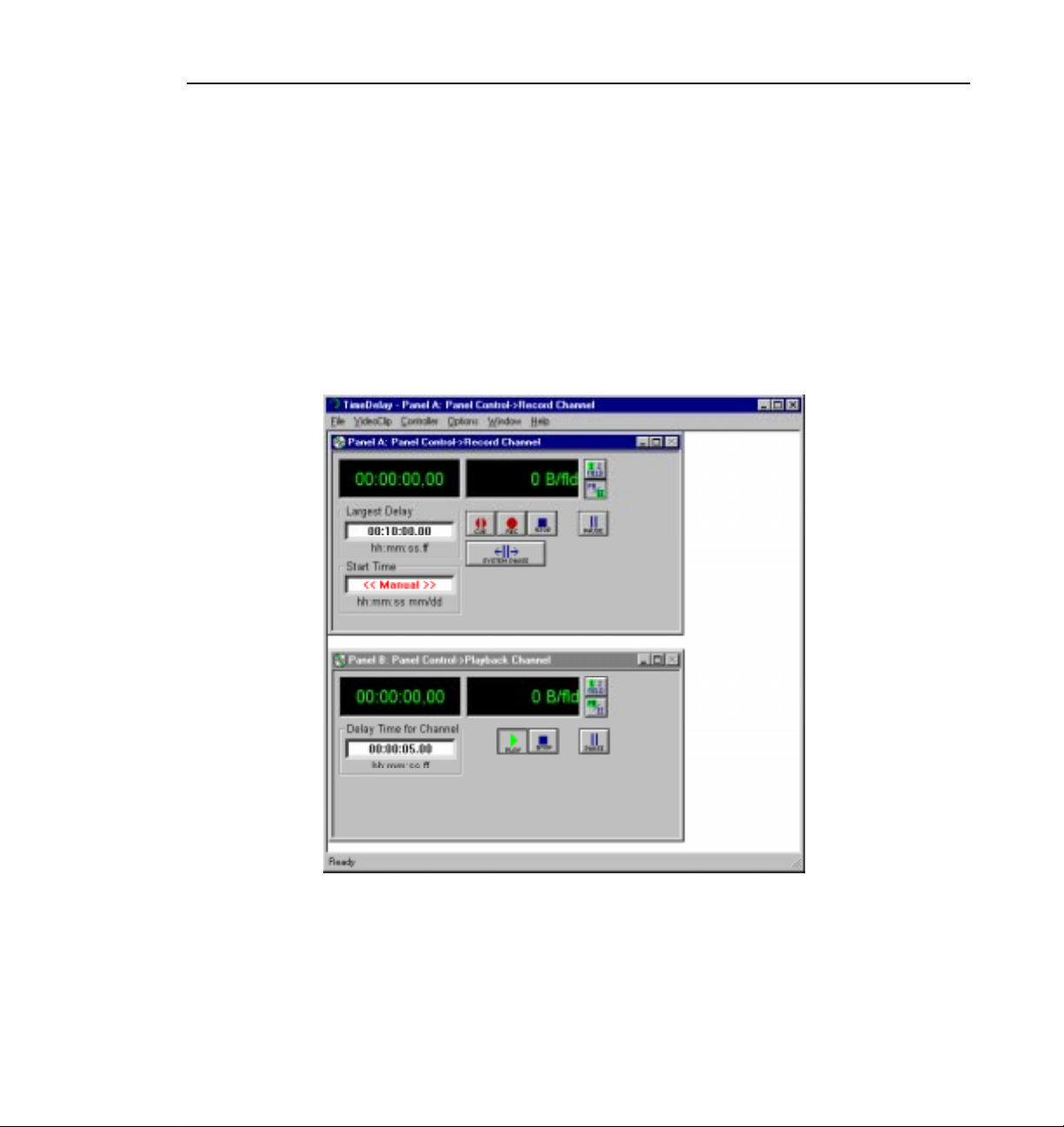
135 TimeDelay window with record/playback pair ..........................................................259
136 Record panel controls ..............................................................................................260
137 Playback panel controls. ..........................................................................................262
138 Censor panel controls ..............................................................................................263
139 Controller Setup dialog box .....................................................................................266
140 Communication Port dialog box ...............................................................................267
141 Profile Options (controller configuration) dialog box ................................................268
142 Edit Compression Presets dialog box ......................................................................269
143 Video crosspoint dialog box .....................................................................................271
144 Timecode Setup dialog box .....................................................................................272
145 Timecode crosspoint dialog box ..............................................................................274
146 Go To Timecode dialog box ....................................................................................278
147 Panel Lockout dialog box ........................................................................................279
148 New Clip dialog box .................................................................................................280
149 Segments in the clip window ...................................................................................283
150 Censor channel .......................................................................................................284
Contents
Profile Family xiii
Page 14

Contents
xiv Profile Family
Page 15

Preface
About this Manual
The Profile® Family User Manualsupports Profile System Software 2.2 for the
industry-standard Profile PDR100 Video Disk Recorder and the PDR200
Profile Video File Server. Profile disk recorders use digital technology to store
and produce broadcast-quality video and CD-quality audio. This manual
documents the standard and optional software applications that run on the
Profile disk recorder:
• The Profile Configuration Manager configures your hardware for input and
output of video and audio, genlock, and system timing.
• The Media Manager manages clips and masters on disk and in a cartridge
library system.
• VdrPanel lets you capture and use video and audio clips.
• The Profile Disk Utility lets you create a file system or load new microcode
for a volume of disks.
• The optional Tool Box Editor logs material and performs simple, cuts-only
edits. It also allows you to create a sequence of clips called a master.
• The optional List Manager allows you to set up simple station automation.
• TimeDelay, also optional, allows you to delay a video feed by a specific
amount of time.
• Other Profile utilities include Profile Log (WinTail), PDR Service, ProLink,
PortServer, plus
fcconfig, a utility used for Fibre Channel networking.
NOTE: This manual assumes that you are familiar with basic
Microsoft Windows operation.
Profile Family xv
Page 16

Preface
Related Documentation
Several manuals related to the Profile Family User Manual include:
• On-line manuals. You can access on-line help for an application at any time
by choosing
• Profile System Version 2.2 Release Notes.
• Profile PDR200 Installation Manual.
• PLS200 Library System Manual.
• PRS200 RAID Storage Instruction Manual.
• PDX103 Disk Expansion Unit Installation Manual.
• PDX208 Disk Expansion Chassis Instruction Manual.
• PRC100 Profile Control Panel User Manual.
• Microsoft Windows NT user documentation.
Help | Help Topics.
xvi Profile Family
Page 17

Terminology and Conventions
Button (graphical) Buttons shown in bold (OK, for example) that you click with
the mouse pointer.
Button (mouse) The two or three buttons on the top of the mouse.
Terminology and Conventions
Choosing Choosing menu items,
means choose the Exit menu item under the File menu.)
Commands Commands (
Clicking Pressing and releasing the mouse button without moving
the pointer.
Ctrl key Hold Ctrl down while pressing other keys in a sequence.
Double-clicking Pressing and releasing the left mouse button twice without
moving the pointer.
Dragging Pressing and holding the mouse button while moving the
pointer.
Moving Changing the location of the pointer on the screen by
moving the mouse.
Pointer An arrow or other graphic on the screen indicating the
current cursor position for selecting or clicking.
Pointing Positioning the pointer on an object on the display by
moving the mouse.
Right-click Pressing and holding the right mouse button.
a:\setup, for example) are shown in bold.
File | Exit, for example. (File | Exit
Profile Family xvii
Page 18

Preface
xviii Profile Family
Page 19
Chapter
1
Introducing the Profile Family
The PDR100 Profile Video Disk Recorder and the PDR200 Profile Video File
Server store broadcast-quality video and CD-quality audio on computer disk
drives rather than on tape, allowing almost instant access to any location in your
video and audio material.
A Profile system is more than just a one-for-one replacement of a VTR: it can
have up to four video channels which is like having four independent VTRs in
one unit. Clips are available to all channels at once, so you can play a clip on
more than one channel at the same time without making a copy of it. Since each
channel is independent of the others, each playback can start at a different time
and at a different place in the clip.
You can even start playing a clip while it’s still being recorded. Just start
capturing the clip on one channel, wait about five seconds, and then play the clip
back on another channel. This kind of control makes the Profile system an ideal
solution if you want to go to air with a clip before you are finished recording it.
Table 1 on page 2 lists and compares other features of the PDR100 and PDR200
in detail.
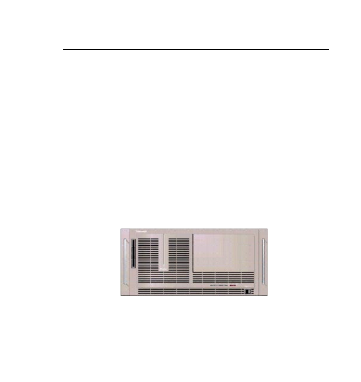
Figure 1. Profile front panel
Profile Family 1
Page 20

Chapter 1 Introducing the Profile Family
Table 1. PDR100 and PDR200 features compared
Feature PDR100 PDR200
Video inputs Analog composite,
component analog (CAV),
serial digital component
Video channels
2 or 4 2 or 4
Analog composite,
component analog (CAV),
serial digital component
(CODECs)
Disk drives Up to eight 4-GB SCSI Up to eight 9-GB Ultra-SCSI
Audio Up to 16 channels, 16-bit
analog standard; digital
embedded optional (625
16 channels, digital standard
(AES/EBU, embedded);
analog optional
only)
Digital audio interfaces None XLR216, BNC216
Analog audio
interfaces
Internal storage at 24
XLR100 PAC208 (8 channel),
PAC216 (16 channel)
3 hours 6 hours
Mb/s
Mainframe bandwidth 24 Mb/s 30 Mb/s
Ethernet 10/100 BaseT 10/100 BaseT
Video network Fibre Channel upgradeable Fibre Channel ready
RS-422 protocols Profile, Louth, Odetics, BVW Profile, Louth, Odetics, BVW
Reference signals NTSC and PAL NTSC and PAL
Line formats 525/60 and 625/50 525/60 and 625/50
Compression Continuously variable
motion JPEG
2 Profile Family
Continuously variable
motion JPEG
Page 21

NOTE: Profile System Software version 2.2 supports both the
PDR100 and the PDR200. In addition, version 2.2 is runs on
Windows® NT™ 3.51 and 4.0.
The PDR100 and PDR200 are supported by the following optional products:
• Fibre Channel interface card
• PDX103 and PDX208 Profile Disk Expansion Units
• PAC208 and PAC216 Analog/Digital Interface chassis (PDR200 only)
• XLR216 and BNC216 Digital Interface chassis (PDR200 only)
• PRS200 Profile RAID Storage System (3 to 96 hours of storage)
• PLS200 Profile Library System
• PRC100 Profile Control Panel unit
• LVS100 Live Controller
• PDRFCD CD-ROM Drive
• Profile Tool Box Editor software
• Profile Tool Box List Manager software
• Profile TimeDelay application software
Profile Family 3
Page 22

Chapter 1 Introducing the Profile Family
A Profile System Overview
The PDR100 and PDR200 are multichannel digital disk recorders capable of
supporting up to four channels with motion JPEG compression. In a fourchannel Profile system, each channel can play back one video and four audio
signals while using several different video formats. In other words, one Profile
unit can replace up to four VTRs, with added benefit of random access to video
and audio data stored on disk.
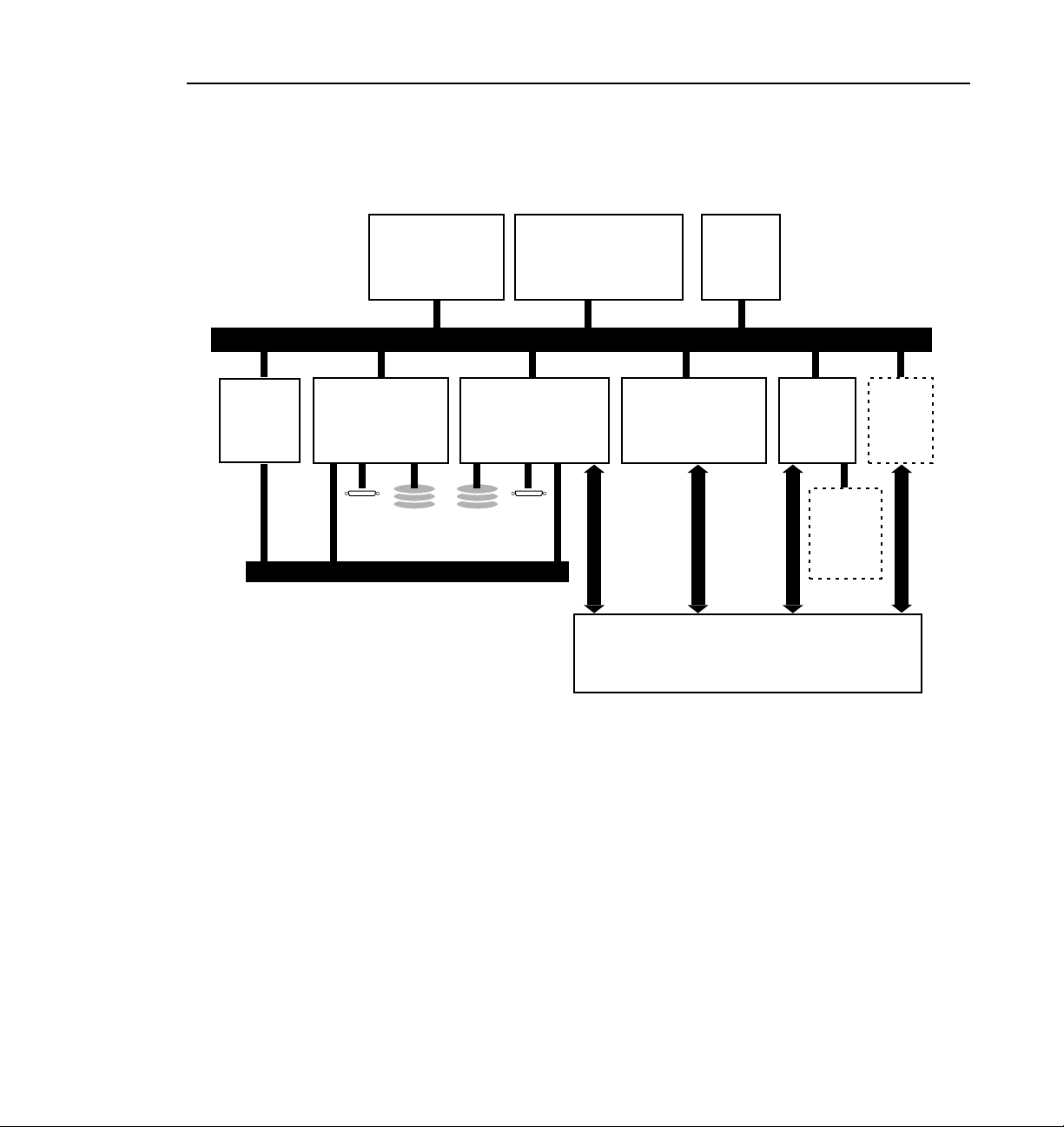
The Profile system has an EISA motherboard with an internal digital video
routing system. There are sixteen EISA slots and one ISA slot used for interface
cards and routing audio data.
The applications processor subsystem, which runs the Windows NT operating
system, is based on an Intel Pentium 133 Mhz with 32 Mbytes of RAM. The
subsystem also has a hard disk drive and a 3.5-inch floppy disk drive, plus a
keyboard, mouse, and an SVGA card.
A video router chip set is integrated on the mother board. It routes video signals
between the video disk system, video effects cards, and video I/O cards. The
video router is a 32 x 32 crosspoint matrix capable of full bandwidth 4:2:2
CCIR 601 8-bit digital video. The video router allows real-time transfer of
video throughout the system without impacting overall system performance.
The video router also makes simultaneous record and playback possible on
separate channels.
Video Disk Subsystem
In the video disk subsystem, video data is compressed and written to disk, or
read from disk and decompressed. This video data is read from and written to
the video router in 8-bit, parallel component digital video format. The video
disk subsystem has disk recorder boards, a SCSI interface to the disks, and an
Intel i960 real-time processor.
The video disk subsystem uses master and slave disk recorder boards with two
SCSI channels on each board. The master disk recorder board comes standard
with a two-channel Profile unit, and a four-channel system adds a slave disk
recorder board. The master board has a Intel i960 real-time processor which
controls compression and the data flows on SCSI channels and CODECs.
A two-channel Profile has two JPEG CODECs and an i960 processor located
on the master disk recorder board. Bidirectional CODEC channels allow
channels to be configured for recording or playback. In a four-channel Profile
system, a slave disk recorder board adds two additional video disk recorder
channels and another SCSI-2 interface to support more disk drives.
4 Profile Family
Page 23

Video Compression
The i960 on the master board is used to control data flow and compression
coefficient loading of the JPEG CODECs. The amount of video compression
varies according to the setting of the compression coefficient. Higher
compression ratios store more data, but the result is lower quality video. On the
other hand, lower compression ratios result in higher quality video and less
storage capacity. Audio is not compressed.
Since JPEG compression ratio can be varied to change the video quality given
available storage time, the amount of storage depends on your choice of
compression ratio. A quick rule of thumb is that five minutes of video—plus
four channels of audio and two channels of timecode—is roughly equal to one
gigabyte of disk storage at a 24 Mbps compressed video data rate. For example,
a PDX208 Disk Expansion unit expands storage up to twelve hours and a
PRS200 RAID Storage System can brings it up to approximately 96 hours.
In addition to video compression, the recorder boards also integrate the audio
data, coming from the EISA bus, with compressed video data. with up to four
channels of audio per channel of video. These recorder boards communicate
with the SCSI-2 interface using a Direct Memory Access (DMA) interface.
Video data is written to and read from the disk over a fast/wide/differential or
Ultra SCSI interface. A maximum of eight 9 gigabyte disk drives are used for
storing the video and audio. Data is striped across disk drives for increased
aggregate bandwidth. External disk drives may be added, such as the PDX208
Disk Expansion unit or the PRS200 RAID Storage system. A maximum of
twelve drives can be supported on a single SCSI-2 bus. The master and slave
recorder boards each have one SCSI-2 interface.
Video Compression
Profile Family 5
Page 24

Chapter 1 Introducing the Profile Family
Video Interface Boards
Video and audio interface boards receive incoming and send outgoing video
and audio data. These boards are responsible for converting the video and audio
to internal formats used by the disk recorder.
There are several video boards that allow a Profile unit to be used with various
standard video formats: Composite analog, serial digital component, or
component analog video are all possible. All boards accept 525/625 (NTSC or
PAL) video standards.
The latest analog composite input and output board offers two input and output
channels per board. The two output channels for this board are similar to the
output channels of the original analog composite board.
The monitor board allows you to display text and burn-in timecode on an output
monitor.
Component analog input allows dithering, auto-timing, and vertical blanking.
As with other inputs, you can automate VITC detection. You adjust input gain
and also select an input format such as Betacam.
A serial digital component board handles both input and output. You can also
enable dithering, auto-timing, and automate VITC detection. The board also
has error detection and handling.
The standard reference genlock board allows you to time your Profile disk
recorder to other devices in a broadcast facility. You can lock a Profile unit to
a PAL or NTSC reference signal (house black). The genlock board also lets you
have four LTC inputs and outputs, one input and one output for each for the four
possible channel.
6 Profile Family
Page 25
Video Interface Boards
Fibre
Channel
Arbitrated
Loop
Networking
• RS-422 ports(8)
• Ethernet LAN I/O
Slave Recorder Bd.
• 2 JPEG CODECs
• Ultra SCSI-2
External SCSI Devices
PCI Bus
Applications Processor
Subsystem
• Intel Pentium
133 Mhz Processor
EISA Bus
Master Recorder Bd.
• Intel i960 real-time
processor
• 2 JPEG CODECs
• Ultra SCSI-2
Video I/O
• Analog Composite
• SDI w/Embedded
Audio
CCIR 601
Video Router
Reference
Genlock
Board
CCIR 601
32 x 32
CCIR 601
Digital
Audio
I/O
Optional
Analog
Audio I/O
(External
CCIR 601
Chassis)
Optional
Mix
Effects
Board
CCIR 601
9955-1
Figure 2. The PDR200 block diagram
Profile Family 7
Page 26

Chapter 1 Introducing the Profile Family
Profile Software Development
The Profile Software Development Kit (SDK) provides an application
programming interface (API) for libraries of Profile functions. You can call
these functions from any language that permits calls to C declared functions.
Software developers can use the API to control the Profile from third-party
hardware devices, for example. The API consisting of six libraries:
• The TekCfg library provides an interface to the Profile configuration.
• The TekPdr library furnishes calls that inventory and manage movies in
Common Movie Format (CMF), an internal file format standard for video,
audio, and timecode.
• The TekRem library makes it possible for a remote Windows NT system on
an x86 processor to control a Profile disk recorder over an Ethernet LAN.
• The TekVdr library provides an interface for playing and recording video
and audio clips.
• The TekVfs library supports low-level access to individual media files in the
media file system.
• The TekVme library controls the optional video mix effects board.
Eight RS-422 serial ports come standard on a disk recorder. A disk recorder can
issue serial commands or receive them from an external device via RS-422
communication lines. The Profile Protocol associates each API call with a
specific number that can be sent over an RS-422 line. The ProLink application
monitors Profile Protocol calls over an RS-422 link, allowing you to use
compatible hardware devices, such as the PRC100 Control Panel, to issue
commands to a Profile unit.
Windows applications are also available to control the Profile system. Your
disk recorder comes with several standard and optional applications. See
“Starting and Closing Profile Applications” on page 11 for more information.
NOTE: Louth and Odetics RS-422 protocols are also supported,
although there is not a one-to-one correspondence between these
protocols and the Profile API. Louth and Odetics protocols do not
allow you full access to the functionality of the
8 Profile Family
Page 27

What to Read First
The order in which you should read the chapters of this manual depends on how
you want to set up your Profile system.
• Before using your Profile unit, you must first configure your video and audio
resources. Refer to Chapter 2, “Using the Profile Configuration Manager.”
• If you are upgrading a PDR100 to version 2.2 of Profile system software
from version 1.4.XX or earlier, you must rebuild your file system. Refer to
Chapter 5, “Using the Profile Disk Utility.”
• Once you have configured your video and audio resources, and rebuilt your
file system, if necessary, you are ready to capture and replay video and audio
clips. Refer to Chapter 4, “Using VdrPanel.”
• To read Profile logs, access your Profile system from a remote PC, or attach
a PRC100 Profile Control Panel, refer to Chapter 6, “Using Profile
Utilities.”
• To learn how to manage media on disk or over Fibre Channel on a Profile
network, see “Using the Media Manager” on page 85.
• If want to use purchase and use optional software applications, see “Using
the Tool Box Editor” on page 189, “Using the List Manager” on page 223,
or “Using TimeDelay” on page 257.
What to Read First
Profile Family 9
Page 28

Chapter 1 Introducing the Profile Family
Starting Your Profile System
Once the unit is properly installed, you are ready to log in. For instructions on
how to install and power-on either a PDR100 or PDR200, see the unit’s
installation manual.
To log in automatically:
1. Power up the Profile unit, and the start up routine begins. During normal start
up, you are logged in automatically and the VdrPanel application starts. You
can hold down the Shift key during start up to interrupt the automatic log in
process.
NOTE: If you stop the automatic log in, or if it fails, the Windows NT
log in screen appears. When logging in, remember that Windows NT
is case-sensitive.
To manually log in:
1. At the Windows NT log in screen, enter the username: profile
2. Use the Tab key to advance to the From field. If your domain name or local
computer name is not displayed in the box, click in the box to access a list of
choices. Select your domain or local computer name from the list.
3. Use the Tab key to advance to the password field.
4. The password appears as asterisks (*) for password security. For the
password, enter:
5. Click OK or press Enter.
NOTE: If a log in error message appears, and all the information is
correct, try deleting the password and clicking
10 Profile Family
profile
OK.
Page 29
Starting and Closing Profile Applications
Starting and Closing Profile Applications
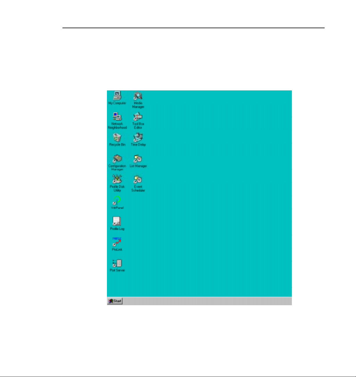
After logging into your Profile system, you see shortcuts for the Profile
applications on the Windows NT desktop.
Figure 3. PDR Application shortcuts on the Windows NT 4.0 desktop
Profile Family 11
Page 30

Chapter 1 Introducing the Profile Family
Starting an Application
To start a Profile application such as VdrPanel using Windows NT 4.0:
• Double-click the shortcut icon on the Windows NT desktop.
Or:
• Choose
Start | VdrPanel.
Or:
• Choose
Start | Programs | PDR Applications | VdrPanel.
To start a Profile application such as VdrPanel using Windows NT 3.51:
1. In Program Manager, double-click the
icon.
2. Double-click the VdrPanel icon in the
Viewing Help
To view the Help for an application:
• Choose
• Click the
Help | Help Topics.
Help button on a dialog box or a toolbar, if available.
To view version information (for VdrPanel in this example):
• Choose
Help | About VdrPanel.
Closing an Application
To close Profile applications:
• Choose
File | Quit, File | Exit or click the Close button.
PDR Applications program group
PDR Applications program group.
12 Profile Family
Page 31

Profile Configuration Manager
The Profile Configuration Manager shown in Figure 4 is an interface for
configuring reference genlock, system timing, video and audio inputs and
outputs. Refer to Chapter 2, “Using the Profile Configuration Manager.”
Profile Configuration Manager
Figure 4. Profile Configuration Manager window
NOTE: You must configure your system resources with this
application before you can use your Profile unit.
Profile Family 13
Page 32
Chapter 1 Introducing the Profile Family
Media Manager
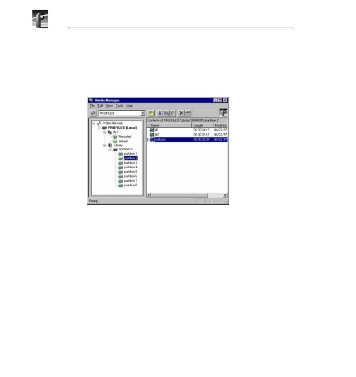
The Media Manager shown in Figure 5 allows you to manage clips and masters
on disk and to archive and restore clips on a library system. Refer to Chapter 3,
“Using the Media Manager.”
14 Profile Family
Figure 5. Media Manager window
Page 33
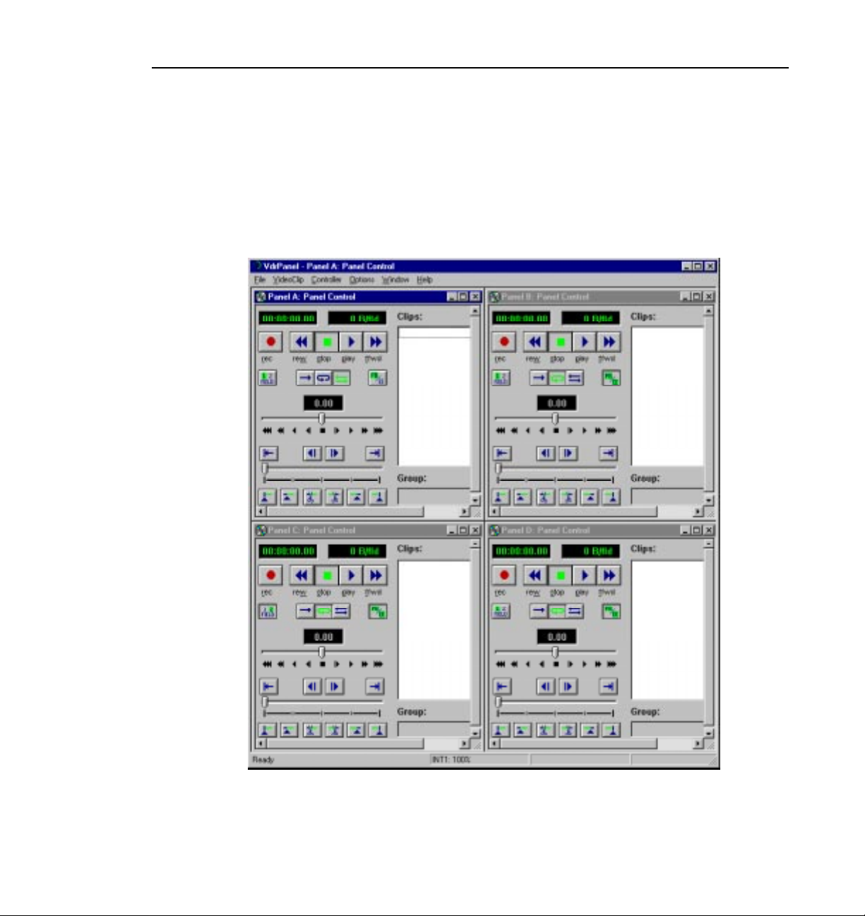
VdrPanel
VdrPanel enables you to capture and trim video and audio clips and then play
those clips back. VdrPanel appears in Figure 6. By default, VdrPanel starts
automatically when you power-on your Profile system. For more information,
refer to Chapter 4, “Using VdrPanel.”
VdrPanel
Figure 6. VdrPanel window
Profile Family 15
Page 34
Chapter 1 Introducing the Profile Family
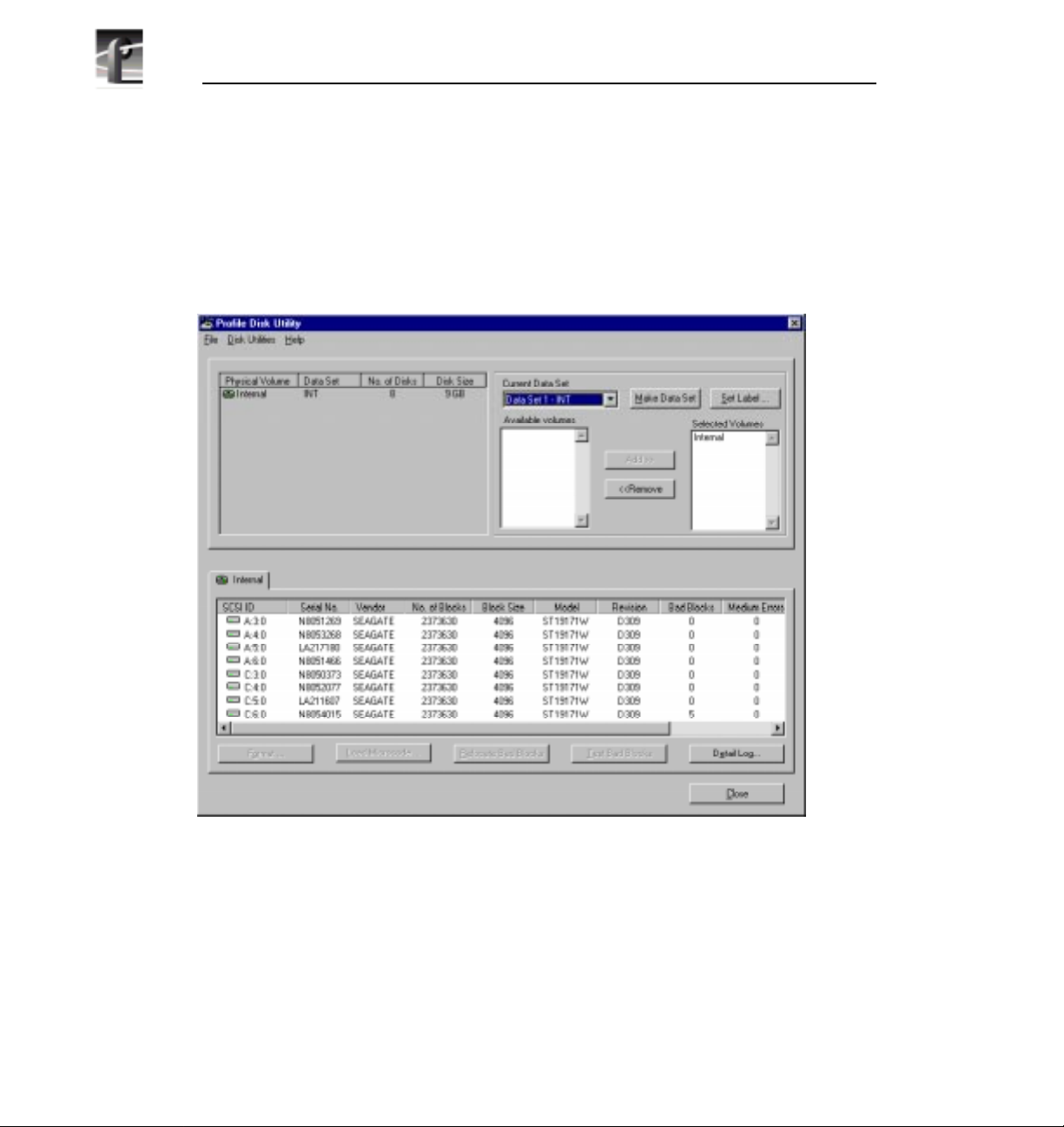
Profile Disk Utility
As shipped from the factory, Profile disks come preformatted and a file system
is already created. Profile Disk Utility allows you to create new file systems,
reformat disks, and change disk labels (see Figure 7). To find out more about
how to use this utility, refer to Chapter 5, “Using the Profile Disk Utility.”
16 Profile Family
Figure 7. Profile Disk Utility window
Page 35
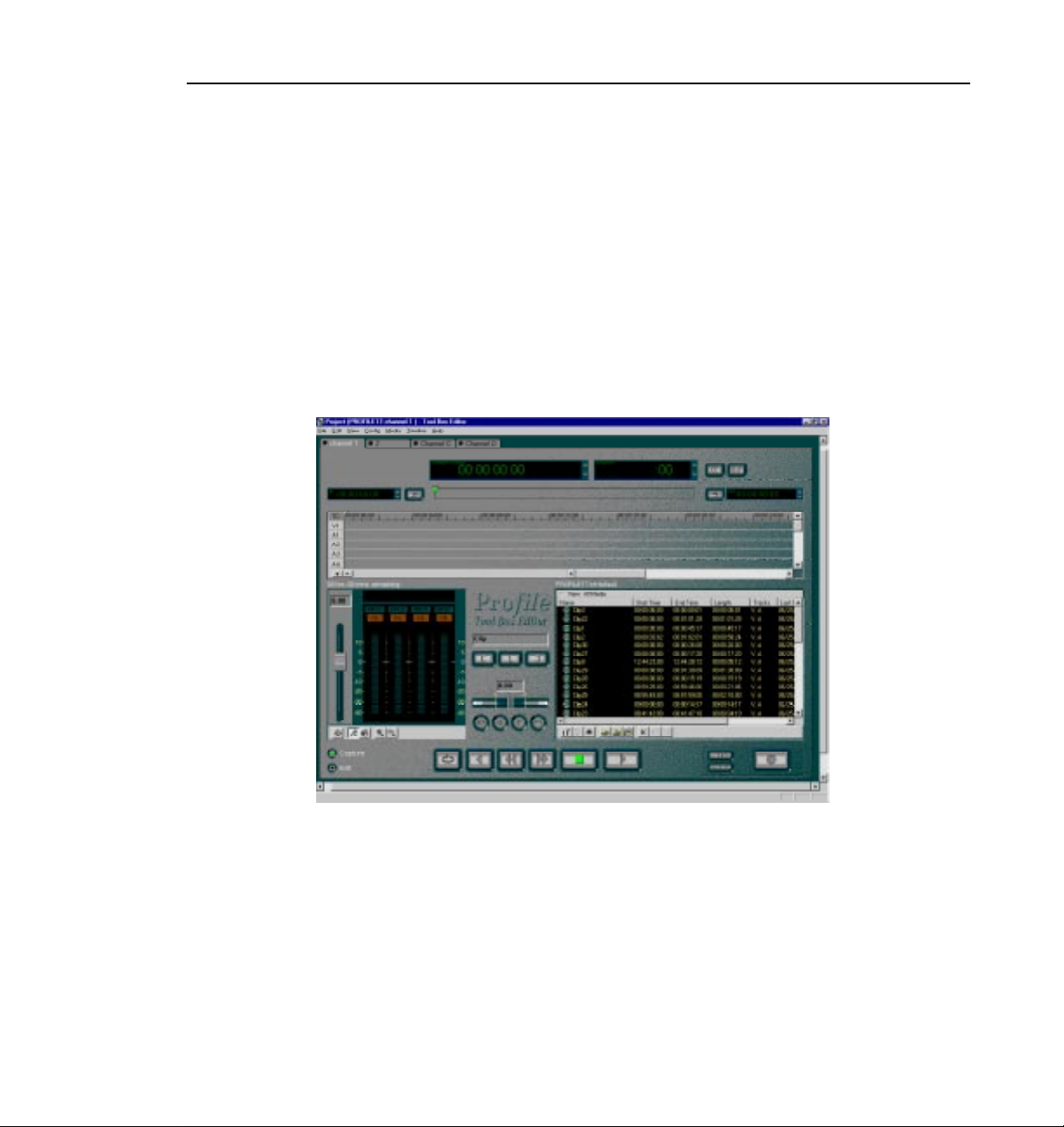
Tool Box Editor
NOTE: A time-locked version of this optional software was shipped
to you with version 2.2 system software. Unlocking this software
requires an additional purchase. Click Purchase in the timelock
dialog box for information on how to purchase this software.
The optional Tool Box Editor shown in Figure 8 lets you create new media by
logging and capturing video and audio clips while also providing an
inexpensive, cuts-only editing system. Refer to Chapter 8, “Using the Tool Box
Editor.”
Tool Box Editor
Figure 8. Tool Box Editor window
Profile Family 17
Page 36
Chapter 1 Introducing the Profile Family
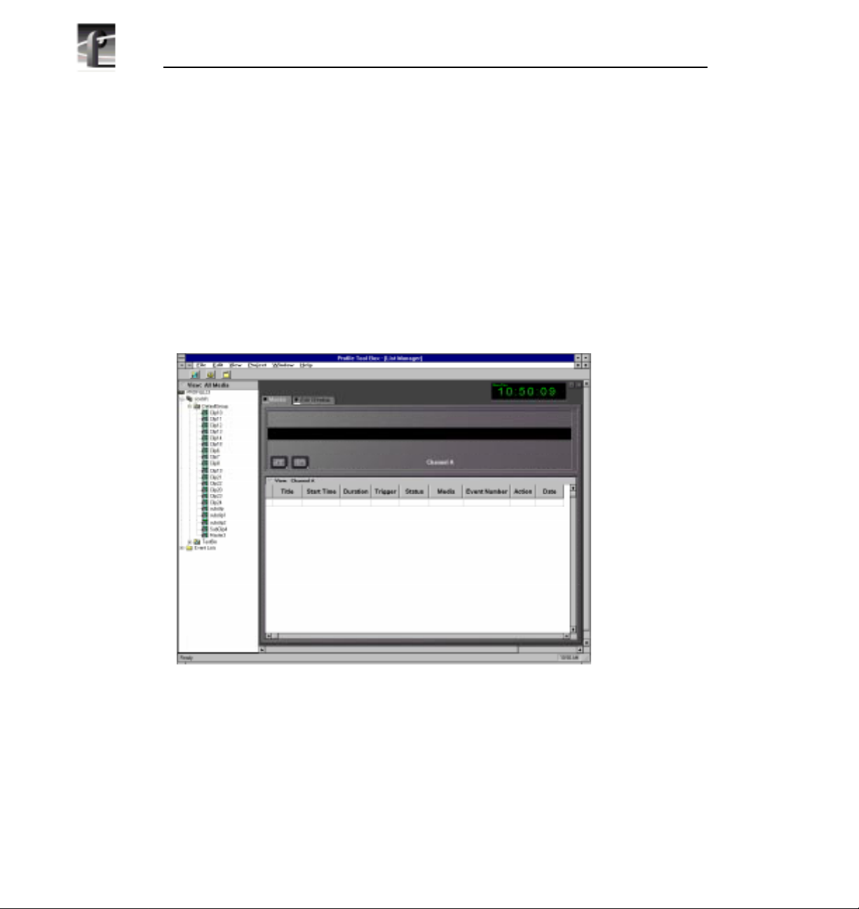
List Manager
NOTE: A time-locked version of this optional software was shipped
to you with version 2.2 system software. Unlocking this software
requires an additional purchase. Click Purchase in the timelock
dialog box for information on how to purchase this software.
The optional List Manager shown in Figure 9 allows you to set up simple
station automation. You can record incoming video at predetermined times,
send incoming video directly to an output, or combine all of these functions to
increase the automation level of you operations. Refer to Chapter 9, “Using the
List Manager.”
18 Profile Family
Figure 9. List Manager window
Page 37
TimeDelay
NOTE: A time-locked version of this optional software was shipped
to you with version 2.2 system software. Unlocking this software
requires an additional purchase. Click Purchase in the timelock
dialog box for information on how to purchase this software.
TimeDelay allows you to delay incoming video by a user-specified amount of
time (see Figure 10). For more information, see Chapter 10, “Using
TimeDelay.”
TimeDelay
Figure 10. TimeDelay window
Profile Family 19
Page 38

Chapter 1 Introducing the Profile Family
Profile Logs
You can view Profile system logs with the graphical log viewer, WinTail. This
log viewer allows you to see the end of a log file. To learn more about how to
view Profile logs, see Chapter 6, “Using Profile Utilities.”
ProLink
ProLink monitors Profile Protocol calls over RS-422 communication lines,
allowing you to use a controller such as the PRC100 Profile Control Panel to
communicate with a Profile system. For more information on Profile Protocol,
see the documentation that accompanies the Profile Software Development Kit.
PortSever
PortSever allows you to control a Profile unit remotely using Ethernet
communications. For example, you can run PortServer on a remote Profile
system so that you can control it over a LAN with it from another Profile.
PortServer is used in conjunction with Fibre Channel operations.
Fibre Channel Support
You can use Fibre Channel video networking capabilities to move media from
one Profile unit directly to another. You can Media Manager use the Fibre
Channel connection to transfer media files between machines, as well as the
listnames and copymovie commands (described in the PDR200 Installation
Manual and thePDR100 Fibre Channel Manual). Ethernet LAN is required for
transferring commands and status information. For more information, see
Chapter 7, “Video Networking.”
20 Profile Family
Page 39

Chapter
2
Using the Profile Configuration Manager
The Profile Configuration Manager provides an easy-to-use interface to
streamline setting up reference genlock, video and audio inputs and outputs,
system timing, and timecode. You use the configuration tree to open the specific
configuration dialog boxes. A graphic representation of the Profile rear panel
shows which boards have been installed. The Configuration Manager window
appears in Figure 11.
Figure 11. Profile Configuration Manager window
To select an item from the configuration tree:
• The configuration tree appears to the left of the display. Clicking on an entry,
such as
of choices, such as if you click on
of choices.
Video Input, expands the list of choices. Clicking on an expanded list
Video Input a second time, collapses the list
Profile Family 21
Page 40
Chapter 2 Using the Profile Configuration Manager
• A single click opens the specific dialog box, closing a previously opened
box, if necessary. A double-click opens the specific dialog box but does not
close any other open dialog boxes. To close all open dialog boxes at once,
choose
Window | Close All.
All changes in a dialog box take place immediately. The
changes from the time a dialog box was opened in the current tab of the dialog
box. The
Undo button is dimmed if there is nothing to undo. The Help button
opens context-sensitive help related to the current dialog box.
By default, the toolbar and status bar are shown in the Configuration Manager
window. To hide the toolbar or status bar:
• Choose
View | Toolbar or View | Status Bar.
To view information about installed boards:
• Choose
Help | Installed Boards Information.
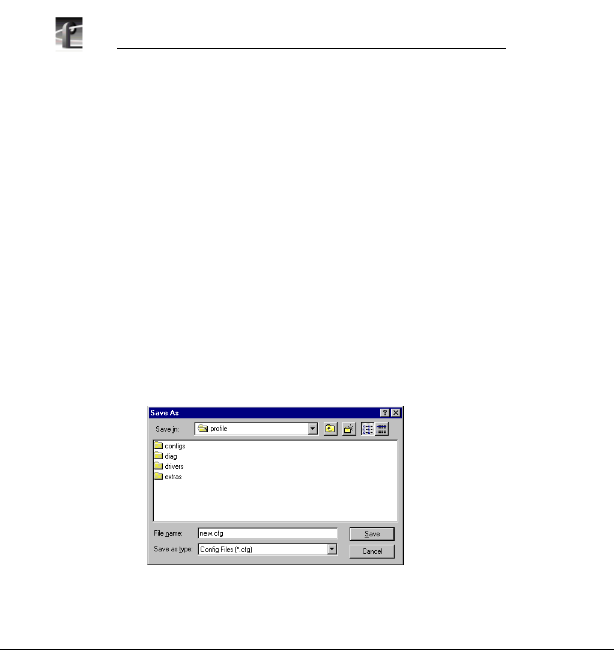
Saving a Configuration File
It is possible to preserve a configuration for later use. You can save your current
overall configuration in a file and then load it later. Configuration files have a
.cfg extension. To save your current configuration in a file:
1. Choose
(Figure 12).
File | Save Current Configuration. The Save As dialog box appears
Undo button will undo
22 Profile Family
Figure 12. Save As dialog box
Page 41

Loading a Configuration File
2. Enter a file name in the File Name box—new.cfg in this example.
3. Press Enter or click
Save. The current configuration is saved.
Loading a Configuration File
To load a configuration file that has been saved previously:
1. Choose
13).
File | Load Configuration File. The Open dialog box appears (Figure
Figure 13. Open dialog box for loading a configuration file
2. A message box warns you that if you load a configuration file, all open
windows are closed. Click
Yes to continue.
3. Double-click a file name in the tree or type the name of the file in the File
Name box—new.cfg in this example.
4. Press Enter or click
Open. The file is loaded as the current configuration.
Profile Family 23
Page 42

Chapter 2 Using the Profile Configuration Manager
Setting Master Timecode
From the Master VITC Setting dialog box, you can conveniently view and
change VITC settings for genlock and all available inputs and outputs. To set
the master timecode (VITC) settings:
1. Choose
toolbar. The Master VITC Setting dialog box appears (Figure 14).
Options | Master Timecode or click theMaster Timecode button on the
Figure 14. Master Timecode dialog box, genlock settings
2. The VITC Present status indicator should be on (green) if VITC is present.
If VITC Present is not on, use one of the following options:
• Manual VITC detection (four-channel LTC version of the reference genlock
board):
- Verify Automatic VITC detect is not selected. If it is, click to toggle it.
- Set VITC Reader Line1 to the expected location of the first Reader Line
24 Profile Family
Page 43

Setting Master Timecode
and VITC Reader Line2 to the second expected Reader Line. If you only
have one VITC line, enter the same value on both Reader lines.
- Check VITC Present. If it is still not on, use a waveform monitor to check
the genlock signal to make sure that VITC exists on these lines.
• Automatic VITC detection only:
- Verify Automatic VITC detect is selected. If it is not, click to toggle it.
The Search Lines are automatically established for NTSC/525 and
PAL/625.
- Check VITC Present. If it is still not on, check the genlock signal to make
sure that VITC exists and is within the expected range.
3. For each video input that should have VITC, select it from the list:
• For automatic VITC detection on analog composite and serial digital
component signals:
- Verify Automatic VITC detect is selected. If it is not, click to toggle it.
- Set VITC Reader Line1 to the beginning of the search line. The minimum
line number is 6 in PAL and 10 in NTSC.
- Check for VITC Present.
• For manual VITC detection on analog composite and serial digital
component signals:
- Verify Automatic VITC detect is not selected. If it is, click to toggle it.
- Set VITC Reader Line1 and VITC Reader Line2 to the lines where VITC
is located. If you only have one VITC line, enter the same value on both
Reader lines.
- Check VITC Present. If it is still not on, double check your line numbers
and try again.
4. For each video output that should have VITC, select it from the list:
• For analog composite on preexisting PDR100 and PDR200 units:
- Verify VITC Generator Enable is checked. If not, click to toggle it.
- Click on Vert. Interval to open the Vertical Interval Line Programming
dialog box.
Profile Family 25
Page 44

Chapter 2 Using the Profile Configuration Manager
- Select the desired VITC lines by checking in the VITC Enable column for
the line. There is not a limit on the number of VITC lines.
- Click
Close to close the Vertical Interval Line Programming dialog box.
• For serial digital component:
- From the Serial Digital Component Video Output dialog box, set the lines
where you want VITC in VITC Generator Line1 and VITC Generator
Line2.
- Verify VITC Generator Enable is checked. If not, click to toggle it.
26 Profile Family
Page 45

Setting the System Timing
A new, factory-default PDR200 is configured so that:
• All outputs are zero-timed to the external reference (house black).
• Each input can lock to and record any stable video input, whether or not the
source is genlocked to an external reference.
NOTE: Serial digital inputs (525 lines) on a PDR100 must be timed
manually.
To adjust system timing:
Setting the System Timing
1. Choose
toolbar. The System Timing dialog box appears (see Figure 15 which shows
an example of how the dialog box looks when the outputs are zero-timed by
default).
- The red line represents the external reference, and the yellow line
- A hashed box represents a timing window or, in other words, the range of
- The external reference, represented at the top of the dialog box, shows a
2. Click any button to the left of the internal reference (genlock) or video output
signal name and the timing edit box appears in the bottom left of the System
Timing dialog box (see Figure 16 which shows the dialog box when the
outputs are E to E timed).
3. In the timing edit box, you can adjust the number of fields (genlock only) or
lines, and also tune these settings with course or fine adjustments. You can
enter a number directly or click an arrow to adjust a setting. The adjustments
and ranges available vary, depending on the type of output you have.
4. Click
Default to return to the default settings.
Options | System Timing or click the System Timing button on the
represents reference genlock.
lines within which the timing is adjusted.
range from –16 to +16 lines. You can scroll past this range by dragging
the pointer on this line in either direction with the mouse.
Close to accept the settings, Undo to return to the previous settings,
NOTE: You must restart your unit for the new system timing setting
to take effect.
Profile Family 27
Page 46

Chapter 2 Using the Profile Configuration Manager
You can also fine tune your system timing settings individually under
Reference Genlock System Input Advanced Adjustment in the Reference
Genlock dialog box. You can also tune individual output settings under Output
Timing Adjustment in under Video Output.
28 Profile Family
Figure 15. System Timing dialog box, zero-timed
Page 47

E to E Timed Outputs
In some applications, you may want to precisely switch an output from a live
video feed to playback of recorded material. Since the live input will be delayed
as it passes through the Profile unit, you must set a corresponding delay on the
playback. The E to E Timed Output option sets a 16-line delay on all the system
outputs, allowing a zero-timed input to be exactly timed with a play to air
signal. To set all your Profile unit output for E to E operations:
E to E Timed Outputs
1. Choose
Options | System Timing or click the System Timing button on the
toolbar. The System Timing dialog box appears.
Figure 16. System Timing dialog box, E to E timed
2. Click E to E Timed Output.
3. Click
Close.
Profile Family 29
Page 48

Chapter 2 Using the Profile Configuration Manager
Adjusting the Timing when Upgrading to 2.2
If you are upgrading an existing PDR100 to system software version 2.2, your
system timing will be left in E to E mode and no changes will be made to your
system timing. The only difference you will see is a numeric offset of 7 lines in
the Line setting under Reference Genlock System Input Advanced Adjustment
in the Reference Genlock dialog box and an offset of nine lines in the Vertical
Line Delay under Output Timing Adjustment under Video Output.
30 Profile Family
Page 49
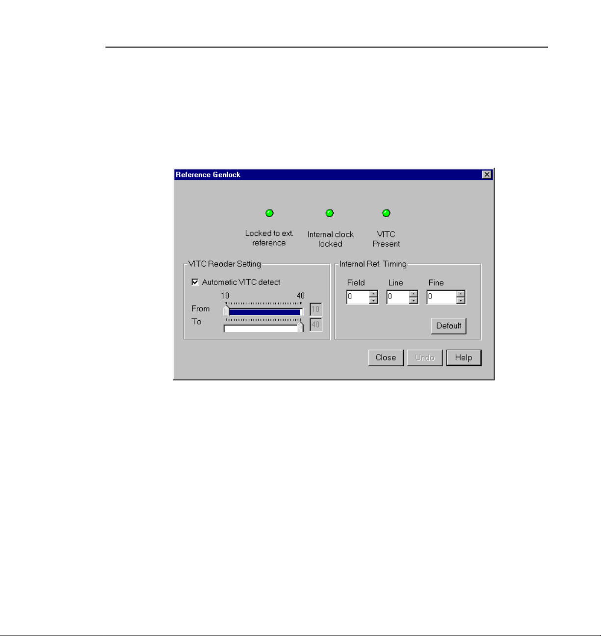
Setting the Reference Genlock
The Reference Genlock dialog box sets the genlock parameters. To open this
dialog box, click or double-click
Reference Genlock dialog box appears.
Genlock from the configuration tree and the
Setting the Reference Genlock
Figure 17. Reference Genlock dialog box
Status Indicators
At the top of the dialog box, the status indicators display the current status of
the Genlock input: Locked to External Reference, Internal Clock Locked and
VITC Present. A green light indicates that the particular status is on. These are
indicators and cannot be edited.
VITC Reader Setting
If you use Automatic VITC detect, the Profile unit uses the range set in the
From and To lines to look for the VITC signals. If Automatic VITC detect is
not used, the unit expects to find the VITC signals on the VITC Reader Line 1
(default 10) or Line 2 (default 12).
Profile Family 31
Page 50

Chapter 2 Using the Profile Configuration Manager
Internal Reference Timing
Use the Field, Line, and Fine entries to adjust the internal timing relative to the
reference input. Changing this setting affects all system timing, including all
output timing and the input synchronized timing window. Click
return to the default values (0,0,0).
NOTE: In order to properly time the disk recorder into the system, the
Internal Reference Timing should only be changed if the
downstream timing requirements cannot be met using the Video
Output Delay Adjustment. This should be done prior to setting
individual output delay adjustments.
Default to
32 Profile Family
Page 51
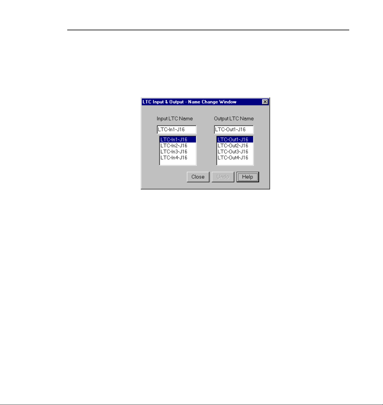
Changing LTC Input and Output Names
Changing LTC Input and Output Names
The LTC Inputs & Outputs renames the LTC inputs and outputs. To open this
dialog box, click or double click
Figure 18. LTC Inputs and Outputs dialog box
1. Select an LTC input or output name.
LTC Input & Output in the configuration tree.
2. Position the text edit cursor within the edit box.
3. Enter the new name or portion of name.
4. The new name appears in the name list.
Profile Family 33
Page 52
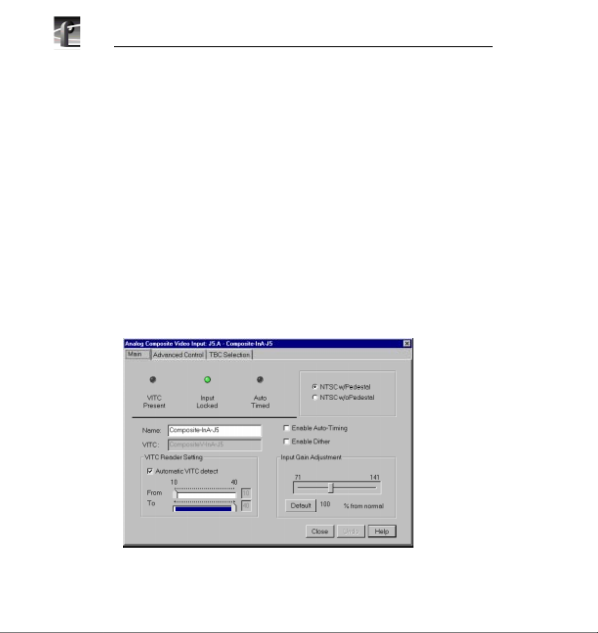
Chapter 2 Using the Profile Configuration Manager
Video Input
You may have analog composite, component analog (CAV), or serial digital
component video inputs installed in your Profile system. The steps to configure
video inputs follow.
Analog Composite Video Input
NOTE: If you have received a new PDR200 video file server from the
factory, you will have the new analog composite video input. If you
have an existing system and are upgrading to Profile system software
version 2.2, see “Analog Composite Video Input for Preexisting
Profile Units” on page 40.
To open the Analog Composite Video Input dialog box, select Video Input
from the configuration tree, and then click or double-click an analog composite
input from the list, such as Composite-InA-J5. This configuration has several
dialog boxes, each opened by clicking the appropriate tab. The Main tab is
displayed when the configuration is opened (see Figure 19). Click on the other
tabs to open the other controls.
Figure 19. Analog Composite Video Input dialog box, Main tab
34 Profile Family
Page 53

Analog Composite Video Input
Status Indicators
These indicators show the current status of the analog composite video input:
VITC Present, Input Locked, and Auto Timed. A green light indicates that a
status is on. These are indicators and cannot be edited.
Video Standard
You have two choices for the video standard of this input board: NTSC with
pedestal or NTSC without pedestal. If you change the standard, restart all tools
that use this channel. The board can serve both standards, but the input can only
accept one at a time.
Renaming the Input Signal
Enter a new name for the input signal in the Name box. For example, if the
signal is a network feed, you could rename it to Network_Feed. The VITC
name, the window title bar, and the configuration tree name change
automatically as you enter the new name. Names can be up to 30 characters, and
can include spaces. To return a renamed signal to the default, delete all the
characters in the text field, and press Enter.
VITC Reader Setting
If you use Automatic VITC detect, the Profile system uses the range set in the
From and To lines to look for the VITC signals. If Automatic VITC detect is
not checked, the system expects to find the VITC signals on the VITC Reader
Line 1 (default 10) or Line 2 (default 12). If the signal is found, the VITC
Present status indicator is turned on.
NOTE: Input must be auto-timed to use automatic VITC detection.
Enable Auto-Timing
Auto-timing determines if the input is synchronized to the reference genlock
signal. The Profile system records time-base corrected video, whether or not it
is also locked to the reference. If auto-timing is enabled and the signal was able
to be timed into the system, then the Auto Timed indicator is turned on.
If you want to use your Profile unit as a switcher and/or have the output video
correctly timed when in E to E mode, the input video must be locked to the
reference and properly timed to the Profile system. To aid in the timing setup,
all video inputs have auto-timing circuits which synchronize input video to the
Profile Family 35
Page 54

Chapter 2 Using the Profile Configuration Manager
internal timing reference as long as the input video is within the auto-timing
sync window (±2 lines). To get to the auto-timing window, the input must be
advanced seven and one-half lines.
The auto-timing circuit is always trying to lock to the signal. If you try to autotime a signal outside of the window, the video signal appears to be broken-up
as it cannot be timed into the system. If the input drifts out of range, it is retimed
as soon as it drops back into range. The Profile unit can use untimed signals if
auto-timing is not enabled, but they are not timed correctly and may cause
jumping and skipping in E to E mode.
NOTE: If you select auto-timing for an input signal and it cannot
auto time with the genlock reference signal, the input signal is not
recorded accurately. If you must record an input that cannot lock,
disable auto timing and record. There may be problems if you are
operating in E to E mode, but the clip won’t play back correctly timed.
Enable Dither
Dithering smooths out roughness caused when a signal is digitized. The LSB
artifacts on 10-bit video feeds are reduced. There is no effect on 8-bit video.
Input Gain Adjustment
You adjust the input gain on the syncs to compensate for any losses in the input.
To adjust the gain, move the slider to the desired value. The range is from 71 to
141 percent (±3 dB) of the input signal. When you click
Adjustment resets to the default value (100 percent).
36 Profile Family
Default, the Input Gain
Page 55

Analog Composite Video Input Advanced Control
Analog Composite Video Input Advanced Control
The Advanced Control tab allows you to select a decode mode, clamp speed,
and vertical interval. Click or double-click on the Advanced Control tab to view
it (see Figure 20).
Figure 20. Analog Composite Video Input dialog box, Advanced Control tab
Decode mode determines how the chrominance and luminance information is
separated for conversion for storage. There are three options:
• Notch Filter. Decode mode separates the chrominance by using a notch
filter around the chrominance subcarrier. This leaves the high frequency
luminance intertwined with the chrominance. A notch decoder readily
determines horizontal lines are line-to-line luminance. Fine vertical lines can
be more difficult.
Profile Family 37
Page 56

Chapter 2 Using the Profile Configuration Manager
• Comb Filter. Decode mode tries to separate high frequency luminance from
the chrominance using the same notch filter as the notch decoder, but also
takes information from the next line. It uses this information to determine if
high frequency is luminance or chrominance. A comb decoder readily
determines finely spaced vertical lines are luminance. A lack of line-to-line
phase alteration causes difficulty with fine horizontal lines.
• Spatial Adaptive. Decoding uses either the comb or notch decoder, on a
pixel by pixel basis, depending on which gives the best results. For
horizontal lines, notch is used; for vertical lines, comb is used.
NOTE: Spatial adaptive decoding uses the high or low threshold
setting.
Clamp Speed
Clamp speed sets the reaction to changing DC levels of the input signal. Click
Enable Clamp Speed to enable it. Speed can be either slow or fast. The fast
clamp speed is more reactive to small DC variations. The slow speed ignores
short-term DC level changes but gradually changes the clamping level to track
the input.
Vertical Interval
These controls set how vertical interval signals are handled. Move the Group
Definition slider to set how many lines are in Groups 1 and 2. In Group 1, Notch
and Pass are available while Blank and Pass are available in Group 2:
• Notch applies notch filtering to the vertical interval video line. This means
that chrominance information and any luminance around the chroma
subcarrier are removed.
• Pass indicates that the vertical video line is passed-through.
• Blank indicated that line the group are blank.
38 Profile Family
Page 57
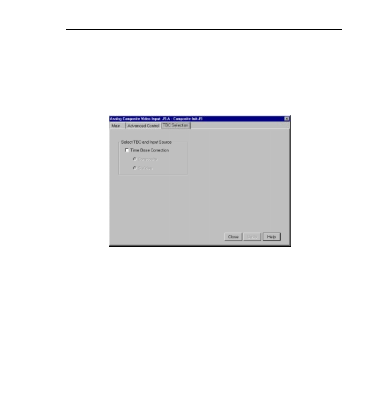
Analog Composite Video Input Time Base Correction
Analog Composite Video Input Time Base Correction
The TBC Selection tab allows you to select Time Base Correction (see Figure
21). When you select Time Base Correction, you can select either composite
input or Super VHS (SVHS or S-video) input. There are two channels available
on this video input board. If Time Base Correction is selected in channel A,
channel B is unselected, and vice versa.
Figure 21. Analog Composite Video Input dialog box, Time Base Correction tab
Profile Family 39
Page 58

Chapter 2 Using the Profile Configuration Manager
Analog Composite Video Input for Preexisting Profile Units
NOTE: These instructions apply only if you are upgrading your disk
recorder to Profile system software version 2.2. If you have a new disk
recorder, follow the instructions in “Analog Composite Video Input”
on page 34.
To open the Analog Composite Video Input dialog box, select Video Input
from the configuration tree, and then click or double-click an analog composite
input from the list, such as Composite-InA-J5. This configuration has several
dialog boxes, each opened by clicking the appropriate tab. The Main tab is
displayed when the configuration box is opened. Click on the other tabs to open
the other controls.
Figure 22. Analog Composite Video Input dialog box, Main tab
Status Indicators
Display the current status of this video input: VITC Present, Burst Present,
Input Locked and Video Timed. The green light indicates a particular status is
on. These indicators cannot be edited.
40 Profile Family
Page 59

Analog Composite Video Input for Preexisting Profile Units
Overwritable Video Standard
This changes the video standard for this input board: NTSC with pedestal,
NTSC without pedestal, or PAL. If you change this standard, restart all tools
that use this channel. The board can serve both standards, but the input can only
accept one at a time.
Renaming the Input Signal
Enter the new name in the Name box. For example, if it is a network feed, you
could rename it to Network_Feed. The VITC name, the window title bar, and
the configuration tree name change automatically as you enter the new name.
Names can be up to 30 characters, and can include spaces. To return a renamed
signal to the default, delete all the characters in the text field, and press Enter.
VITC Reader Setting
If you use Automatic VITC detect, the disk recorder uses the range set in the
From and To lines to look for the VITC signals. If Automatic VITC detect is
not used, the disk recorder expects to find the VITC signals on the VITC Reader
Line 1 (default 10) or Line 2 (default 12). If the signal is found, the VITC
Present indicator is turned on.
NOTE: Input must be auto-timed to use automatic VITC detection.
Enable Auto-Timing
Auto-timing determines if the input is synchronized to the reference genlock
signal. The disk recorder records time-base corrected video whether or not it is
also locked to the reference. If auto-timing is enabled and the signal was able
to be timed into the system, then the Auto Timed indicator is turned on.
If you want to use the disk recorder as a switcher and/or have the output video
correctly timed when in E to E mode, the input video must be locked to the
reference and properly timed to the disk recorder. To aid in the timing setup, all
video inputs have auto-timing circuits which synchronize input video to the
internal timing reference as long as the input video is within the auto-timing
sync window (±1 lines). To get to the auto-timing window, the input must be
advanced seven and one half lines.
The auto-timing circuit is always trying to lock to the signal. If you try to autotime a signal outside of the window, the video signal appears to be broken-up
as it cannot be timed into the system. If the input drifts out of range, it is retimed
Profile Family 41
Page 60

Chapter 2 Using the Profile Configuration Manager
as soon as it drops back into range. The disk recorder can use untimed signals
if auto-timing is not enabled, but they are not timed correctly and may cause
jumping and skipping in E to E mode.
NOTE: If you select auto-timing for an input signal and it cannot
auto time with the genlock reference signal, the input signal is not
recorded accurately. If you must record an input that cannot lock,
disable auto timing and record. There may be problems if you are
operating in E to E mode, but the clip won’t play back correctly timed.
Enable Dither
Dithering smooths out roughness caused when a signal is digitized. The LSB
artifacts on 10-bit video feeds are reduced. There is no effect on 8-bit video.
Input Gain Adjustment
Adjust the input gain on the syncs to compensate for any losses in the input.
You can adjust the gain manually or use the AGC (audio gain control). AGC
enables the internal quality monitoring circuit to automatically adjust the gain
to keep the sync level constant.
To manually adjust the gain, turn off AGC and move the slider to the desired
value. The range is from 45 to 142 percent (±3 dB) of the input signal for
NTSC/525 and 82 to 142 percent for PAL/625. When you click
Input Gain Adjustment resets to the default value (100 percent).
Default, the
42 Profile Family
Page 61

Analog Composite Video Input Advanced Control
Analog Composite Video Input Advanced Control
The Advanced Control tab allows you to select a Decode mode. Decode mode
determines how the chrominance and luminance information is separated for
conversion for storage. Click or double-click on the Advanced Control tab (see
Figure 23).
Figure 23. Analog Composite Video Input dialog box, Advanced Control tab
There are four options:
• Notch. Decoder mode separates the chrominance by using a notch filter
around the chrominance subcarrier. This leaves the high frequency
luminance intertwined with the chrominance. A notch decoder readily
determines horizontal lines are line-to-line luminance. Fine vertical lines can
be more difficult.
Profile Family 43
Page 62

Chapter 2 Using the Profile Configuration Manager
• Comb. Decoder mode tries to separate high frequency luminance from the
chrominance using the same notch filter as the notch decoder, but also takes
information from the next line. It uses this information to determine if high
frequency is luminance or chrominance. A comb decoder readily determines
finely spaced vertical lines are luminance. A lack of line to line phase
alteration causes difficulty with fine horizontal lines.
• Spatial Adaptive. Decoding uses either the comb or notch decoder, on a
pixel by pixel basis, depending on which gives the best results. For
horizontal lines, Notch is used; for vertical lines, Comb is used.
• Temporal/Spatial Adaptive. Decoding uses both the next line and the same
line in the alternate field in the calculations. This decoder uses all of the
properties of the Spatial Adaptive decoder, plus it uses Temporal (interfield
changes) information. The phase change (or lack of) from field to field helps
determine whether high frequency should be decoded as chrominance or
luminance.
NOTE: Spatial adaptive and temporal/spatial adaptive decoding use
the high or low threshold setting.
Temporal/Spatial Option
This control is only used if the Decode Mode is set to Temporal/Spatial
Adaptive. The threshold determines the amount of motion allowed between
alternate fields to still have the Temporal decoder recognize the pixel. High
allows more motion than Low.
Noise Reduction
These controls enable and set various noise reduction methods:
• Enable Luma and Chroma Reduction applies the Level and Threshold
settings to use a feedback noise reduction scheme on the decoded input
signals after they have been separated into chrominance and luminance. The
Level and Threshold settings determine the amount of weight the feedback
signal has in comparison to the input signal. The Threshold range takes into
consideration the amount of motion in the picture. Use the sliders to adjust
the ranges. Be sure Enable Luma and Chroma Reduction is checked for the
reduction values to be applied.
44 Profile Family
Page 63

Analog Composite Video Input Advanced Control
• Enable Quiet Line acts as a noise reference. If the Quiet line is noise-free,
the rest of the signal should also be noise-free. This allows the decoder to not
mistake noise for motion. If the Quiet Line is enabled, the line values for
Field 1 and Field 2 are used. Use the sliders to set the line values for each
field. Click on
Default Lines to return to the default values.
• Enable Impulse Noise Reduction automatically filters out noise spikes,
such as amplifier crackling.
NOTE: If reduction of impulse noise is selected, the disk recorder
automatically switches the clamp speed to slow. It is recommended
that you use the spatial adaptive decode option, although it does not
automatically switch.
Clamp Speed
Clamp speed sets the reaction to changing DC levels of the input signal. Speed
can be Adaptive, Slow, Medium, or Fast. The faster the clamp the more reactive
it is to small DC variations.
Slow ignores short-term DC level changes but gradually changes the clamping
level to track the input. Adaptive uses the best clamp for the current video input.
The Clamp Speed also helps with white noise reduction. Adaptive is the best
choice for white noise reduction. Do not use Adaptive for impulse noise, use
Slow and the Impulse Noise Detection option from the Noise Reduction group.
NOTE: If you set AGC (audio gain control) to automatic on the main
screen, clamp speed cannot be selected.
Profile Family 45
Page 64

Chapter 2 Using the Profile Configuration Manager
Analog Composite Video Input Vertical Interval
The controls under the Vertical Interval tab sets how the vertical interval signals
are handled. There are different vertical interval line numbers in the dialog
boxes, depending on your video standard—NTSC/525 or PAL/625. Click or
double-click on the Vertical Interval tab (see Figure 24).
Figure 24. Analog Composite Video Input dialog box, Vertical Interval tab
46 Profile Family
Page 65

Analog Composite Video Input Vertical Interval
For each Video Line, position the slider pointer to one of the following:
• Normal indicates the vertical interval video line is passed-through.
• Notch applies notch filtering to the vertical interval video line (chrominance
information and any luminance around the chroma subcarrier are removed).
• Pass On Y passes luminance information straight through. This is useful for
VITC and closed-caption or data filtering.
• Delete removes the vertical interval video line and replaces it with black.
Profile Family 47
Page 66

Chapter 2 Using the Profile Configuration Manager
Component Analog Video Input
To open the Analog Component Video Input (CAV) dialog box, select Video
Input from the configuration tree, and then click or double-click an analog
component input from the list, such as CAV-InA-J9.
Figure 25. Component Analog Video Input dialog box (CAV)
Status Indicators
Display the current status of the Genlock input: Video Present, VITC Present,
and Auto Timed. The green light indicates the particular status is on. These
indicators cannot be edited.
Overwritable Video Standard
Changes the video standard for this input board: NTSC/525 or PAL/625. If you
change this standard, you must restart all tools that use this channel. The board
can serve both standards, but the input can only accept one at a time.
48 Profile Family
Page 67

Component Analog Video Input
Renaming the Input Signal
Enter the new name in the Name field. For example, if the signal is a Betacam
input, rename it Betacam_1. The VITC name, window title bar name, and the
configuration tree name automatically change as you enter the new name.
Names can be up to 30 characters, and can include spaces. To return a renamed
signal to the default, delete all the characters in the text field, and press Enter.
VITC Reader Setting
If you to use Automatic VITC detect, the disk recorder uses the range set in the
From and To lines to look for the VITC signals. If Automatic VITC detect is
not used, the disk recorder expects to find the VITC signals on the VITC Reader
Line 1 (default 10) or Line 2 (default 40). If the signal is found, the VITC
Present indicator is turned on.
NOTE: Input must be auto-timed to use automatic VITC detection.
Input Gain Adjustment
Move the adjustment slider to the desired value. The range is from 70 percent
to 140 percent (3 dB) for the input signal for both 525 and 625. When you click
Default, the Input Gain Adjustment resets to the default value (100 percent).
on
Enable Auto-Timing
Auto-timing determines if the input is synchronized to the reference genlock
signal. The disk recorder records time-base corrected video whether or not it is
also locked to the reference.
If you want to use the disk recorder as a switcher and/or have the output video
correctly timed when in E to E mode, the input video must be locked to the
reference and properly timed to the disk recorder. To aid in the timing setup, all
video inputs have auto-timing circuits which synchronize input video to the
internal timing reference as long as the input video is within the auto-timing
sync window (±1 lines). To get to the auto-timing window the input must be
advanced seven and one half lines.
The auto-timing circuit is always trying to lock to the signal. If you try to autotime a signal outside of the window, the video signal appears to be broken-up
as it cannot be timed into the system. If the input drifts out of range, it is retimed
Profile Family 49
Page 68

Chapter 2 Using the Profile Configuration Manager
as soon as it drops back into range. The disk recorder can use untimed signals
if auto-timing is not enabled, but they are not timed correctly and may cause
jumping and skipping in E to E mode.
NOTE: If you select auto-timing for an input signal and it cannot
auto time with the genlock reference signal, the input signal is not
recorded accurately. If you must record an input that cannot lock,
disable auto timing and record. There may be problems if you are
operating in E to E mode, but the clip plays back correctly timed.
If auto-timing is enabled, and the signal was able to be timed into the system,
the Auto Timed indicator is turned on.
Enable Dither
Dithering smooths out roughness caused when a signal is digitized. The LSB
artifacts on 10-bit video feeds are reduced. There is no effect on 8-bit video.
Vertical Blanking
If you enable vertical blanking, for the 525 standard, lines 1 through 9 and 264
through 272 are blanked; for the 625 standard, lines 1 through 5, 311 through
317, 624, and 625 are blanked.
50 Profile Family
Page 69
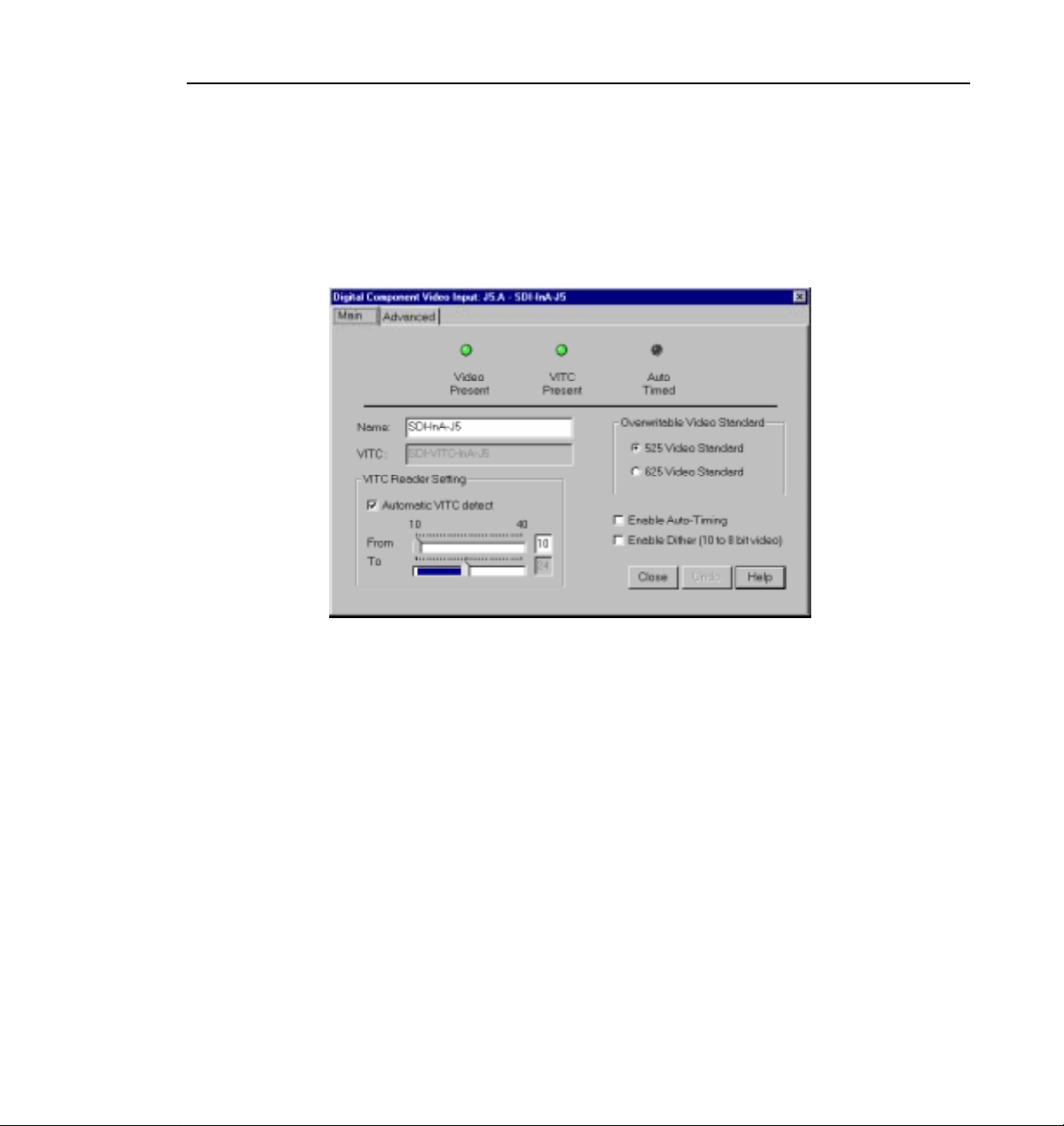
Serial Digital Component Video Input
To open the Serial Digital Component Video Input dialog box, click or double-
Video Input on the configuration tree, and then select a digital component
click
input from the list, such as SDI-InA-J13.
Serial Digital Component Video Input
Figure 26. Serial Digital Component Video Input dialog box
Status Indicators
Display the current status of this video input: Video Present, VITC Present, and
Auto Timed. The green light indicates that a particular status is on. These
indicators cannot be edited.
Overwritable Video Standard
Changes the video standard for this input board: NTSC/525 or PAL/625. If you
change this standard, you must restart all tools that use this channel. The board
can serve both standards, but the input can only accept one at a time.
Profile Family 51
Page 70

Chapter 2 Using the Profile Configuration Manager
Renaming the Input Signal
Enter the new name in the Name field. For example, if SDI-InA-J13 is a
dedicated satellite feed, rename itSatellite_1. The VITC name, window title bar
name, and the configuration tree name automatically change as you enter the
new name. Names can be up to 30 characters, and can include spaces. To return
a renamed signal to the default, delete all the characters in the text field, and
press Enter.
VITC Reader Setting
If you to use Automatic VITC detect, the disk recorder uses the range set in the
From and To lines to look for the VITC signals. If Automatic VITC detect is
not used, the disk recorder expects to find the VITC signals on the VITC Reader
Line 1 (default 10) or Line 2 (default 12). If the signal is found, the VITC
Present indicator is turned on. Line 1 and Line 2 cannot be more than 14 apart.
NOTE: Input must be auto-timed to use automatic VITC detection.
Enable Auto-Timing
Auto-timing determines if the input is synchronized to the reference genlock
signal. The disk recorder records time-base corrected video whether or not it is
also locked to the reference.
If you want to use the disk recorder as a switcher and/or have the output video
correctly timed when in E to E mode, the input video must be locked to the
reference and properly timed to the disk recorder. To aid in the timing setup, all
video inputs have auto-timing circuits which synchronize input video to the
internal timing reference as long as the input video is within the auto-timing
sync window (±1 lines). To get to the auto-timing window the input must be
advanced seven and one half lines.
The auto-timing circuit is always trying to lock to the signal. If you try to autotime a signal outside of the window, the video signal appears to be broken-up
as it cannot be timed into the system. If the input drifts out of range, it is retimed
as soon as it drops back into range. The disk recorder can use untimed signals
if auto-timing is not enabled, but they are not timed correctly and may cause
jumping and skipping in E to E mode.
52 Profile Family
Page 71
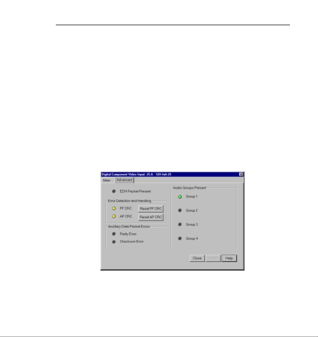
Serial Digital Component Video Input Advanced
NOTE: If you select auto-timing for an input signal and it cannot
auto time with the genlock reference signal, the input signal is not
recorded accurately. If you must record an input that cannot lock,
disable auto timing and record. There may be problems if you are
operating in E to E mode, but the clip plays back correctly timed.
If auto-timing is enabled, and the signal was able to be timed into the system,
the Auto Timed indicator is turned on. Also, Line 1 can still be adjusted, but
Line 2 is always equal to Line 1 + 14.
Enable Dither
Dithering smooths out roughness caused when a signal is digitized. The LSB
artifacts on 10-bit video feeds are reduced. There is no effect on 8-bit video.
Serial Digital Component Video Input Advanced
Click the Advanced tab to view the Serial Digital Component Video Input
Advanced settings.
Figure 27. Serial Digital Component Video Input, Advanced tab
These advanced settings allow you to determine whether the EDH packet is
present, which audio groups are present, and which errors are present: Full
Field (FF) CRC or Active Picture (AP) CRC, plus parity and checksum errors.
Profile Family 53
Page 72
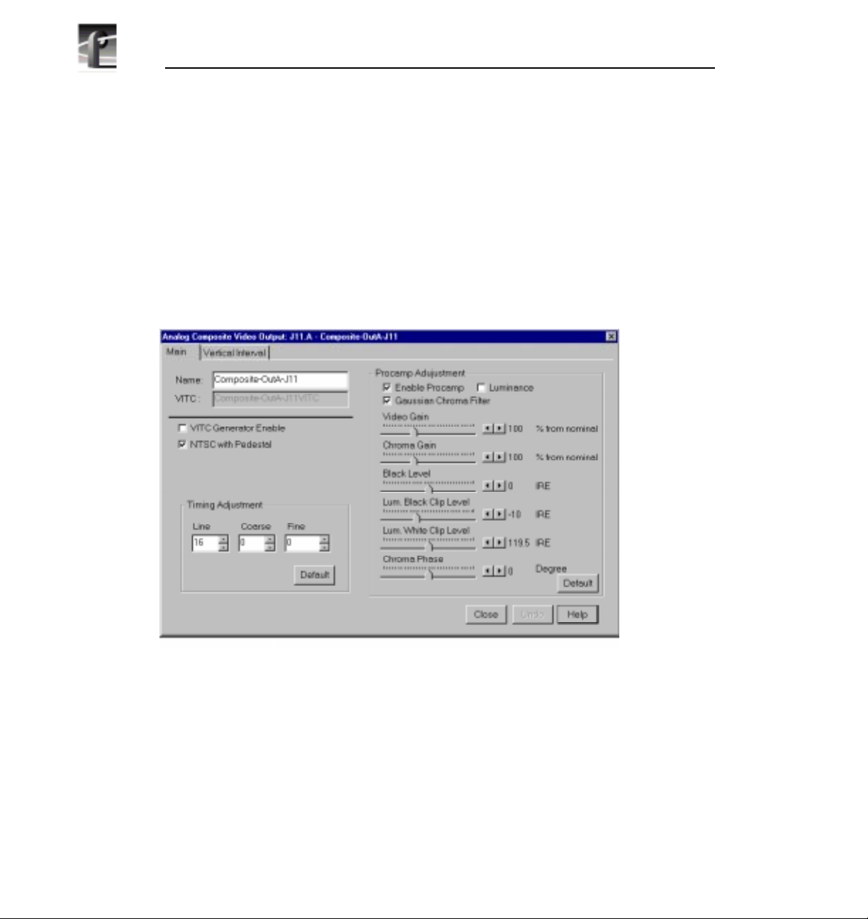
Chapter 2 Using the Profile Configuration Manager
Video Output
You can configure either analog composite or serial digital component video
output on your Profile system, depending on which boards are installed.
Analog Composite Video Output
To open the Analog Composite Video Output dialog box, select Video Output
from the configuration tree and click or double-click an analog composite
output from the list, such as Composite-OutA-J11.
Figure 28. Analog Composite Video Output dialog box
Changing the Procamp Adjustments
The Procamp Adjustment group modifies the output signal to compensate for
any irregularities in the signal path. All changes take place immediately.
• Enable Procamp must be checked before anything in this group can be
adjusted. This enables you to setup the Procamp and then disable it without
losing the setup.
54 Profile Family
Page 73

Analog Composite Video Output
• Luminance (enabled) specifies only the luminance portion of the signal is
output. The signal is black and white.
• Gaussian Chroma Filter determines the type of filter used on the
chrominance portion of the signal. If the Gaussian Chroma Filter is selected,
the filter has a long slow roll-off to prevent ringing. If it is not selected, then
a brickwall filter is used. Although this may introduce ringing into the signal,
it maintains the integrity of the signal for multiple processing. Use the
Gaussian Filter as a last step before transmission and if ringing suppression
is required. Do not use this filter if you are doing multiple processes/passes
on the signal or if the material is in component form.
The Procamp controls are adjusted with either the slider bars or arrow buttons.
The corresponding numeric values are displayed in the text boxes.
• Video Gain raises or lowers the overall amplitude of the video signal. It has
a range of 50 to 200 percent of nominal.
• Chroma Gain changes the amplitude of the chrominance portion of the
signal to change the color intensity. It has a range of 50 to 200 percent of
nominal.
• Black Level sets the voltage level of the reference black level. This is
expressed in mV in the PAL video standard and in IRE units in NTSC. The
range in the PAL standard is –140 to 140 mV. The range in the NTSC
standard is –20 to +20 IRE.
• Chroma Phase sets the colors by varying the phase of the chrominance
subcarrier. The range is –45 to +45.
• Luminance Black Clip Level is the point where the procamp clips the
luminance portion of any video that drops below this level. For PAL, the
range is –150 mV to 0 mV and –20 IRE to 7.5 IRE (or 0 IRE if pedestal is
not selected) in the NTSC standard.
• Luminance White Clip Level follows the same logic, only it clips any
luminance above the set threshold. Its range in the PAL standard is 700 to
909.5 mV and 100 to 139.5 IRE in the NTSC standard.
• Default Procamp resets the Procamp to the factory-defined levels.
Profile Family 55
Page 74

Chapter 2 Using the Profile Configuration Manager
Changing the Output Timing Adjustments
The Output Timing Adjustment group enables you to adjust the timing of the
output signal to compensate for any additional delays in your system. Any
changes you make in this group take place immediately. You can delay at the
following levels, to get the exact amount of delay required:
• Vertical Line level (from –2 to +148 lines)
• Coarse Horizontal level (from –100 to +100 ms)
• Fine Horizontal level (from –100 to +100 ms)
Use the slider bars to set the delay amount. The timing adjustments are
generally done with a waveform monitor, visually moving the signal so that it
matches the reference. Click on
which is the point where the output signal timing is aligned with the reference
genlock signal.
Default Timing to reset the slider bars to 0,
Changing Output Settings
• Name changes the signal name. For example, if this is a dedicated signal to
a main switcher, rename it Switcher_1. The VITC Name automatically
tracks the signal name. Names can be up to 30 characters, and can include
spaces. To return a renamed signal to the default, delete all the characters in
the text field, and press Enter.
• VITC Generator Setting places VITC on specified lines and/or erases lines
in the vertical interval.
- If VITC Generator Enable is selected, VITC is placed on the lines given
in VITC Generator Line 1 and 2. If you only want one line, use the same
number in both text boxes.
- If VITC Erase Enable is selected, it replaces lines (mostly vertical
interval, but into the active video) with black. The range of lines is given
in the Start and End sliders.
56 Profile Family
Page 75

Analog Composite Video Output Vertical Interval
Analog Composite Video Output Vertical Interval
The Vertical Interval tab brings up the Analog Composite Video Output
Vertical Interval controls. The vertical interval line numbers change depending
on the selected video standard.
Figure 29. Analog Composite Video Input Vertical Interval dialog box
The settings determine how the Vertical Interval signals are handled. The video
on these lines can have the Procamp Enabled (the settings are the same as the
regular video), the VITC Enabled (if VITC Generator Enable from the Output
Settings group is checked), or the input can Pass Video through. All or none of
the options can be selected for each line. There are three default buttons:
Default Procamp, Default VITC, and Default Pass Video; to reset these
specified values back to the factory presets.
NOTE If the Pass Video box is not checked, the input video is
replaced with black. Do not check Pass Video for VITC lines. Pass
Video overrides VITC Insertion.
Profile Family 57
Page 76

Chapter 2 Using the Profile Configuration Manager
Analog Composite Monitor Output
To open the Analog Composite Monitor Output dialog box, select Video
Output from the configuration tree, and then click or double-click a monitor
output from the list, such as Monitor-Out-J12.
Figure 30. Analog Composite Monitor Output dialog box, Main tab
Displaying text on a monitor is good way to help identify where the output is
coming from. To display text on an attached monitor, click
Name changes the signal name. For example, you could rename it to
Monitor_1. Names can be up to 30 characters, and can include spaces. To return
a renamed signal to the default, delete all the characters in the text field, and
press Enter.
Under Text Layout, you can select either a small or large font, a dim or bright
white character display, and a transparent or opaque background for the
lettering. With the small font, you get twelve lines and twenty-four columns;
with the large, you get six lines and thirteen columns.
58 Profile Family
Show Text.
Page 77

Analog Composite Monitor Output Burn-in Timecode Tab
To enter text, click in the text entry box and start typing where you want the text
displayed on the monitor. Legal characters are: a-z A-Z 0-9 / ! ? + - = ( ) < > ‘
“ . , . Use _ (underbar) for transparent space.
To clear entire monitor, click
Clear Display. Click the button again to display
text once more. Under Windows NT 3.51, this button appears as a check box.
Analog Composite Monitor Output Burn-in Timecode Tab
The Burn-in Timecode tab brings up the controls for displaying burn-in
timecode on the monitor (see Figure 31).
Figure 31. Analog Composite Monitor Output dialog box, Burn-in Timecode tab
To display timecode on an attached monitor, select Show/Hide Window.
To display a large timecode window, select
Under Window Position, you can select the
Large Window Size.
Start Row and Start Column for the
timecode with the sliders. This determines where the timecode is displayed on
the monitor screen. The current row and column are displayed on the right.
Profile Family 59
Page 78

Chapter 2 Using the Profile Configuration Manager
You can display the timecode in one of four formats: black on white, white on
black, black on background, or white on background.
Serial Digital Component Video Output
To open the Serial Digital Component Video Output dialog box, select Video
Output from the configuration tree, and then click or double-click a digital
component output from the list, such as SDI-OutA-J5.
Figure 32. Serial Digital Component Video Output dialog box
• Name changes the signal name. For example, if the signal named SDI-OutAJ13is a dedicated signal to a main switcher, rename itSwitcher_1. The VITC
name automatically tracks the signal name. Names can be up to 30
characters, and can include spaces. To return a renamed signal to the default,
delete all the characters in the text field, and press Enter.
• VITC Generator Setting places VITC on specified lines and/or erase lines
in the vertical interval.
- If VITC Generator Enable is selected, VITC is placed on the lines given
in VITC Generator Line 1 and 2. If you only want one line, use the same
number in both text boxes.
- If VITC Erase Enable is selected, it replaces lines (mostly vertical
interval, but into the active video) with black. The range of lines is given
in the Start and End sliders.
60 Profile Family
Page 79

Serial Digital Component Video Output Advanced
• Timing Adjustment sets the timing of each output with respect to the
Reference Genlock System Input Advance which, in turn, is set with respect
to the external reference input. With the Reference Genlock System Input
Advance set to the factory default of 0, the outputs have an adjustment range
of –2.5 lines to +148 lines of delay. The Fine delay is in nanoseconds and the
Line delay is in lines.
Serial Digital Component Video Output Advanced
Click the Advanced tab to view the Serial Digital Component Video Output
Advanced settings (Figure 33).
Figure 33. Serial Digital Video Output dialog box, Advanced tab
The Advanced tab allows you to set options for error detection and handling
(EDH). If Insert EDH Packets is checked, Full Frame CRC and Active Picture
CRC are inserted into the video stream. If Blank Ancillary Data is checked,
ancillary data information is inserted into the video stream.
Profile Family 61
Page 80
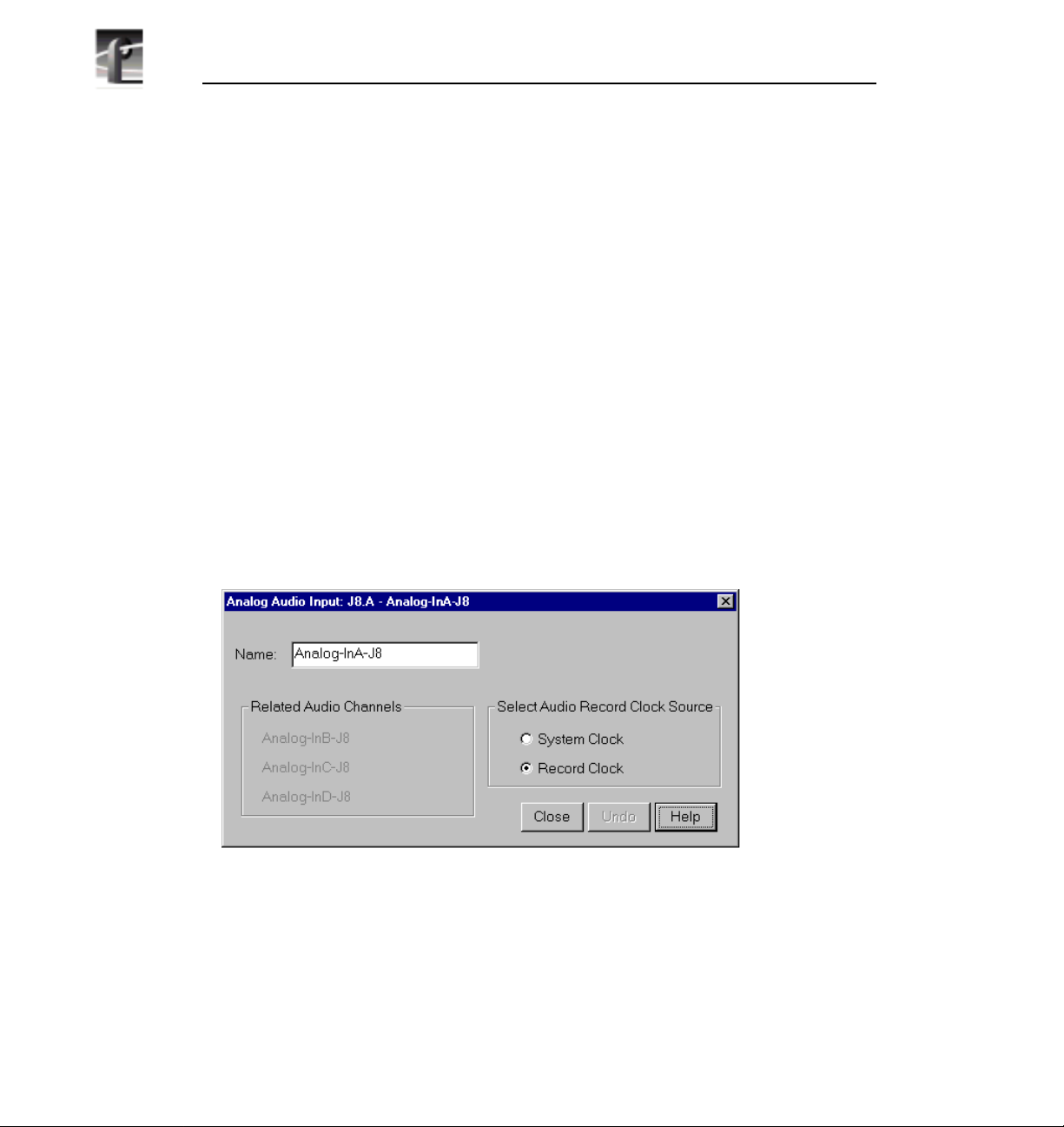
Chapter 2 Using the Profile Configuration Manager
PDR100 Audio
The PDR100 supports both analog and serial digital embedded (625 only)
audio inputs and outputs, depending on which boards are installed your the
PDR100 system. Audio in the PDR100 is routed using the EISA bus with data
flow controlled by a real time controller and the audio interface card. The
analog audio card is capable of converting four channels of analog audio to
digital audio (and vice versa) using 16-bit/48kHz conversion. The input and
output data flow to the card via the EISA bus, with sample clocks coming from
a video interface card, such as the analog composite board or the SDI board.
However, the analog audio card can only have one clock operating at a time. If
the card is used as an input device, it must have the clock that originates on the
video board associated with the audio.
Analog Audio Input
To open the Analog Audio Input dialog box, select Audio Input from the
configuration tree, and then click or double-click an analog audio name from
the list, such as Analog-InA-J8. The dialog box appears, as shown in Figure 34.
• Name allows you to change the signal name—from Analog-InA-J8 to Audio
One, for example. Signal names can be up to 30 characters long, and can
include spaces. The window title bar name and the configuration tree name
automatically change as you enter the new name. To return a renamed signal
to the default, delete all the characters in the text field, and press Enter.
62 Profile Family
Figure 34. Analog Audio Input dialog box
Page 81

• Related Audio Channels lists the audio channels that are related to the
signal name.
• Select Audio Record Clock Source allows you to select either the system
clock or the record clock.
Digital Audio Input
To open the Digital Audio Input dialog box, select Audio Input from the
configuration tree, and then click or double-click a digital audio name from the
list.
Digital Audio Input
Figure 35. Digital Audio Input dialog box
• Name changes the signal name—Audio_1, for example. Names can be up to
30 characters, and can include spaces. The window title bar name and the
configuration tree name automatically change as you enter the new name. To
return a renamed signal to the default, delete all the characters in the text
field, and press Enter.
• Audio Groups Present is represented by four status indicators, one per
audio group. The green light indicates that the particular status is on. These
indicators cannot be edited.
Profile Family 63
Page 82
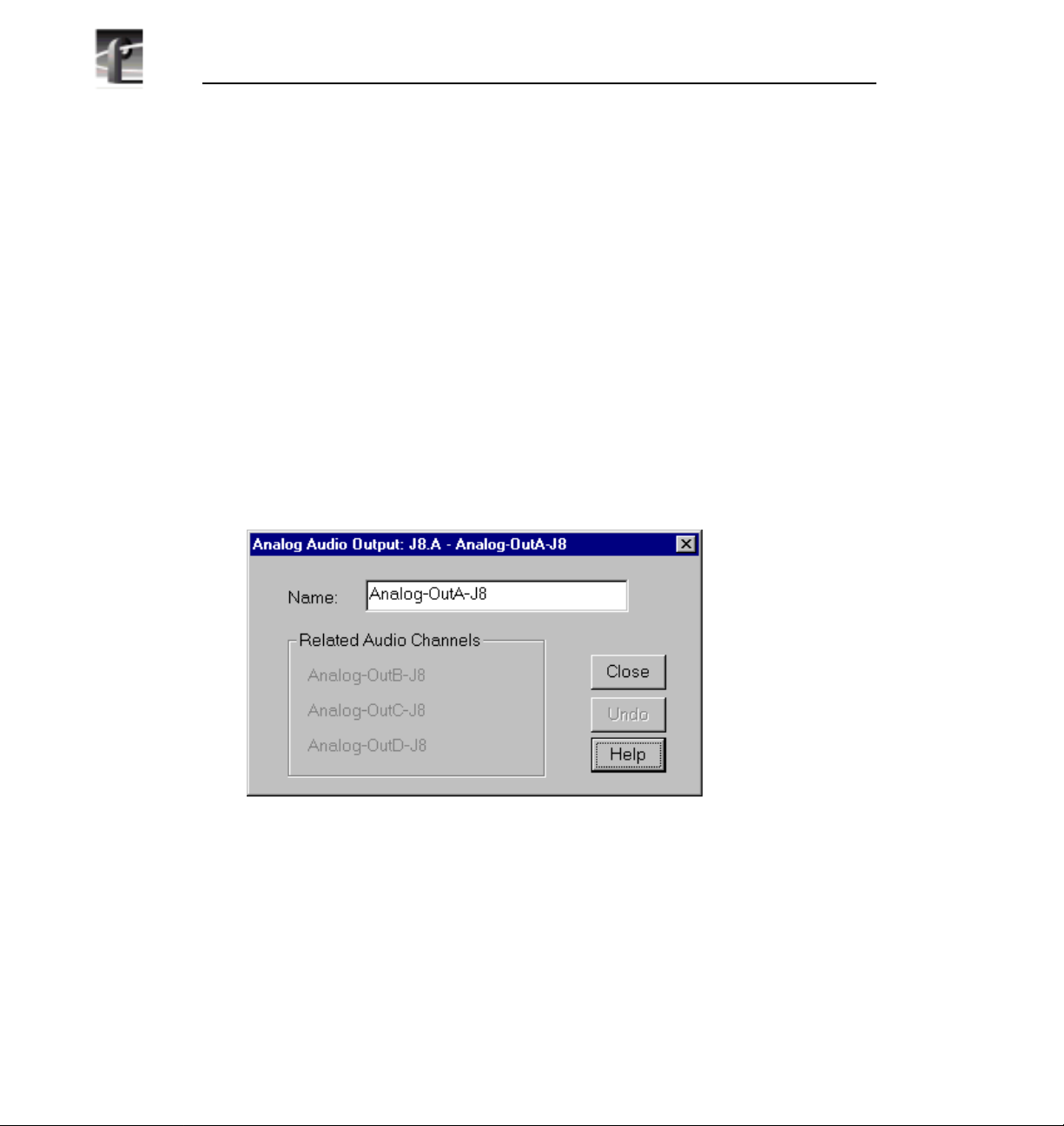
Chapter 2 Using the Profile Configuration Manager
• Associated Video Input Channel lists the name of the digital component
video input channel associated with the audio signal.
• Related Audio Channels lists the audio channels that are related to the
signal name.
• Selected Audio Receive Group is in the range 1–4. To change the group,
click on the button associated with the group.
• Selected Group Status represents parity error and check sum error with a
status indicator for each. The green light indicates an error condition. These
indicators cannot be edited.
Analog Audio Output
To open the Analog Audio Output dialog box, select Audio Output from the
configuration tree, and then click or double-click an analog audio name from
the list.
• Name changes the signal name—Audio_Out_1, for example. Names can be
up to 30 characters, and can include spaces. The window title bar name and
the configuration tree name automatically change as you enter the new name.
To return a renamed signal to the default, delete all the characters in the text
field, and press Enter.
• Related Audio Channels lists the audio channels that are related to the
signal name.
64 Profile Family
Figure 36. Analog Audio Output dialog box
Page 83
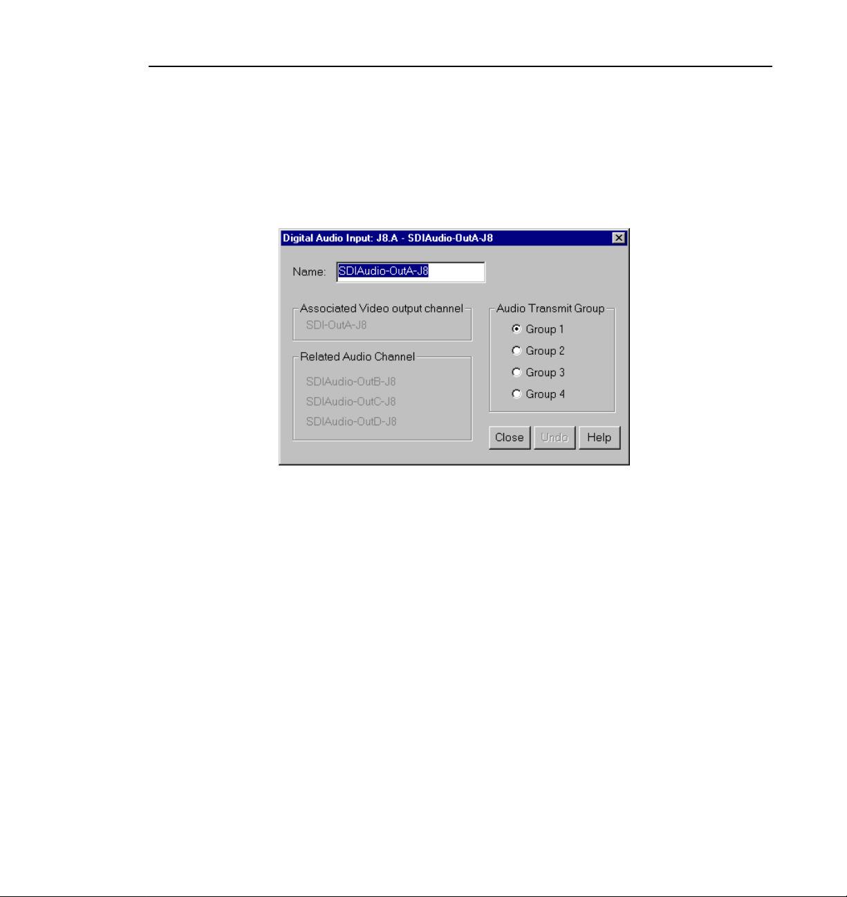
Digital Audio Output
To open the Serial Digital Audio Output dialog box, select Audio Output from
the configuration tree, and then click or double-click a digital audio name from
the list.
Digital Audio Output
Figure 37. Digital Audio Output dialog box
• Name changes the signal name—Audio_Out_1, for example. Names can be
up to 30 characters, and can include spaces. The window title bar name and
the configuration tree name automatically change as you enter the new name.
To return a renamed signal to the default, delete all the characters in the text
field, and press Enter.
• Associate Video Output Channel lists the name of the associated video
output channel.
• Related Audio Channels lists the audio channels that are related to the
signal name.
• Audio Transmit Group changes the audio transmit group in the range 1–4.
To change the group, click on the button associated with the group.
Profile Family 65
Page 84

Chapter 2 Using the Profile Configuration Manager
PDR200 Audio
The PDR200 audio architecture accepts and simultaneouly processes sixteen
audio inputs and outputs at up to four simultaneous clock rates. Internally, all
audio is processed in floating point at 48kHz with a selectable storage
resolution of 16 or 20 bits. Inputs may be individually clocked in groups of four,
and any clock group may be referenced to the system reference (house black)
or any one of four video inputs. Output clocking is synchronous to system
reference. Sample rate conversion is available for all inputs (30 to 50kHz),
providing uniform storage at 48kHz.
The PDR200 can be configured to operate with analog, AES/EBU digital, or
embedded (SMPTE 272M Level A) audio, depending on which options are
installed in your system. All three audio formats are supported without external
conversion equipment. Analog audio is only available with an optional
PAC208 or PAC216 Analog/Digital Interface chassis. You can expand the
number of XLR or BNC connectors for AES/EBU audio with an optional
XLR216 or BNC216 Digital Interface chassis.You can choose an audio format
for each video channel. For example, you could enable analog audio on one
channel, embedded audio on another, and AES/EBU on the rest.
NOTE: Do not turn off sample rate conversion or use AES/EBU as a
reference unless you are certain that all inputs and outputs are
synchronous.
Analog Audio Input
In analog audio input, you can change audio channel names, check the channel
overload status, or adjust line levels in decibels. Click
or click
1. Expand
66 Profile Family
Help for context-sensitive Help. To configure analog audio input:
Audio Input dialog box appears (Figure 38). The channel numbers on the left
refer to the physical input connectors on the audio input box. Ch. 01 refers
Undo to cancel changes,
Audio Input, and then click one of the Analog Channels. The Analog
Page 85
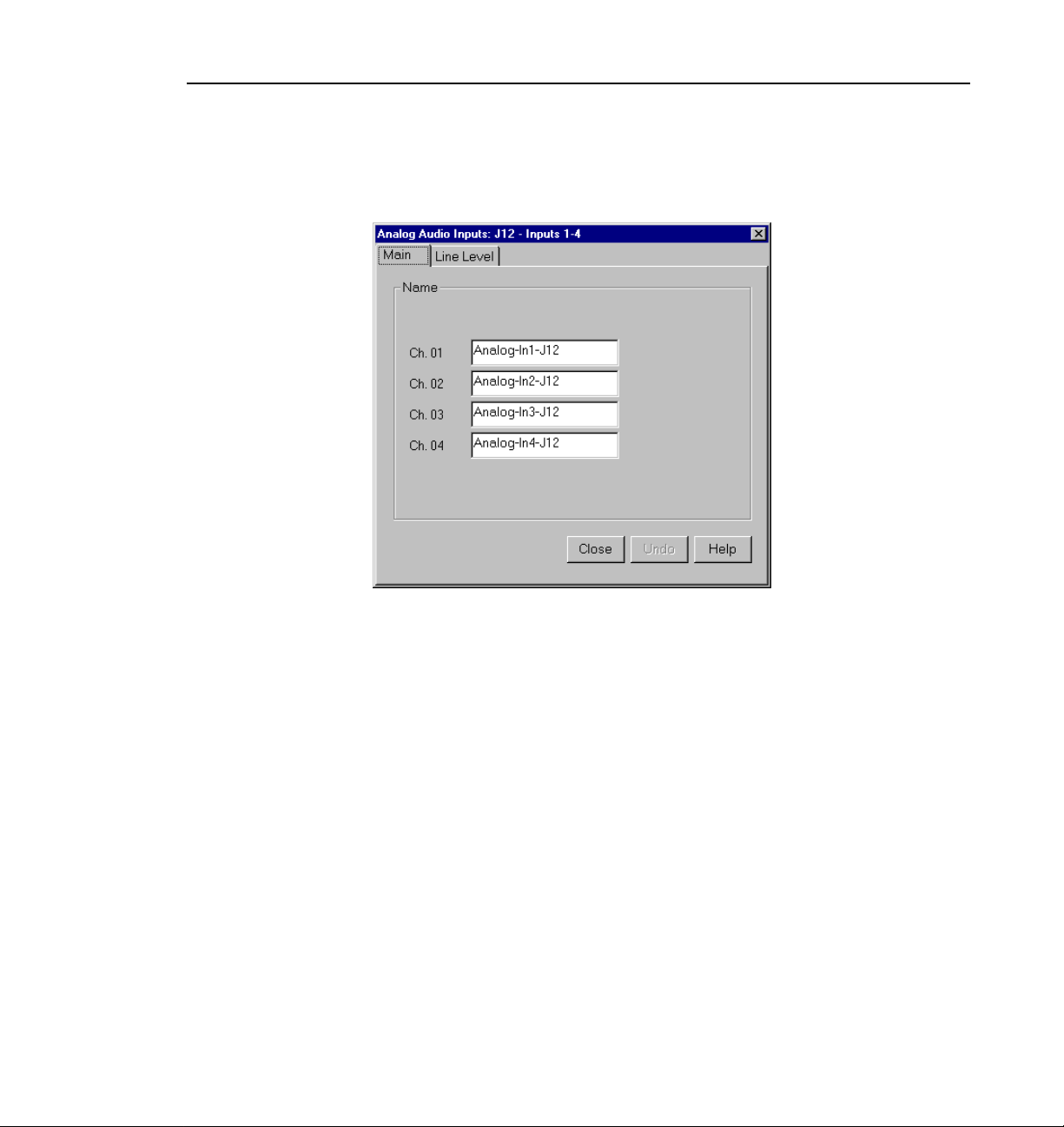
Analog Audio Input
to the first connector, and Ch. 02 refers to the second connector, and so forth.
Figure 38. Analog Audio Input dialog box, Main tab
2. Click the Main tab, if it is not already visible.
3. Click in the box of the input channel whose name you want to change. A
channel name can have up to 30 characters.
4. After you have changed the channel names, click
Close or another tab.
Profile Family 67
Page 86
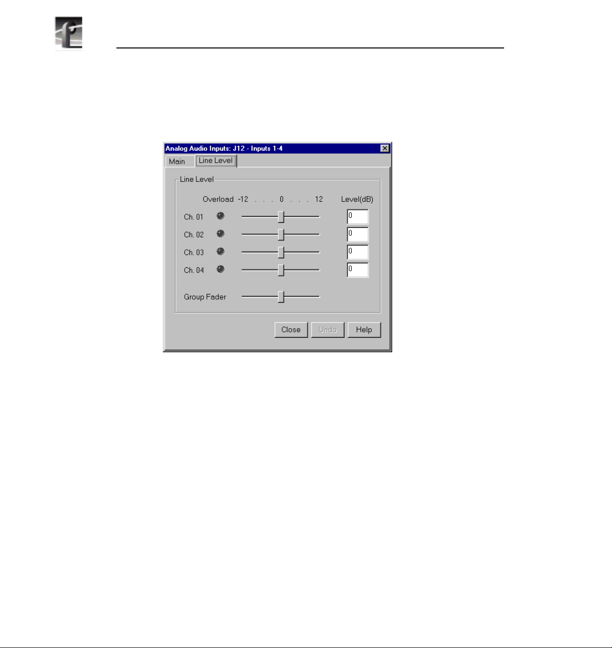
Chapter 2 Using the Profile Configuration Manager
To trim the line level or view overload status:
1. In the Analog Audio Input dialog box, click the Line Level tab (Figure 39).
Figure 39. Analog Audio Input dialog box, Line Level tab
2. The line level range is –12 to +12 dB. If you trim the line level for an
individual channel with the slider handle, the line level is incremented by 1
dB; clicking on either side of the slider handle increments the line level by
0.5 dB. The Level boxes show the current line level. If you enter a number
directly into a Level box, the line level number is rounded to the nearest ±0.5
dB.
3. To adjust the trim for all channels at once, use the
the Group Fader moves all channels at once, it maintains the individual
channel differences.
4. If a channel is overloaded, the Overload indicator is on. This means that the
incoming audio is clipping.
5. After you have adjusted the line levels, click
68 Profile Family
Group Fader slider. While
Close or another tab.
Page 87
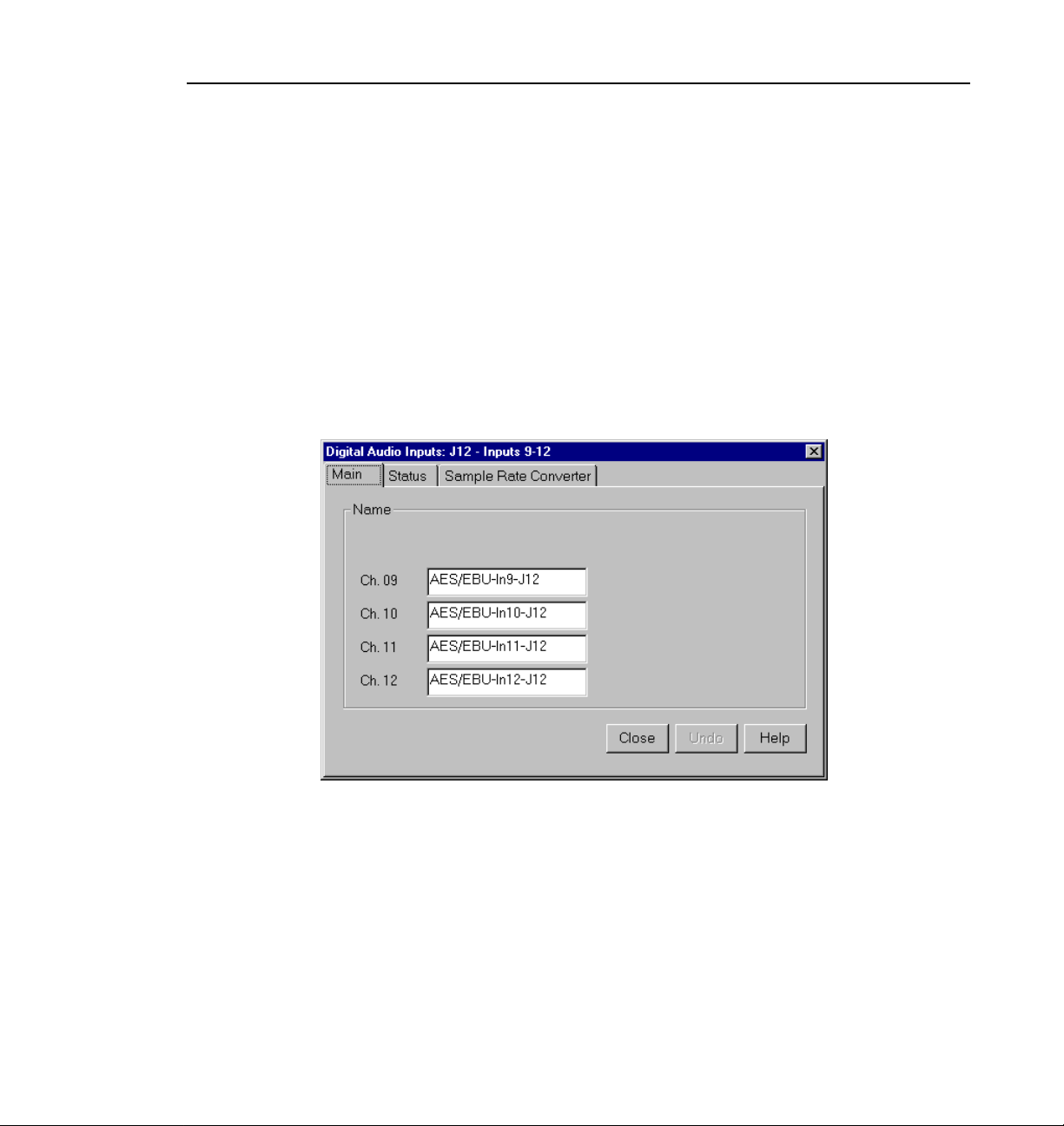
Digital Audio Input
In digital audio input, you can change channel names, check the status of
channel errors, and change the setting of the sample rate converter. Click
if you want to cancel any changes, or click Help for context-sensitive Help.
To configure digital audio input:
1. Expand Audio Input, and then click one of the Digital Channels to bring up
the Digital Audio Input dialog box (Figure 40). The channel numbers on the
left refer to the physical input connectors on the audio input box. Ch. 01 and
Ch. 02 refer to the channel pair on the first connector, and Ch. 03 and Ch.
04 refer to the pair on the second connector, and so forth.
Digital Audio Input
Undo
Figure 40. Digital Audio Input dialog box, Main tab
2. Click the Main tab, if it is not already visible.
3. Click in the box of the input channel whose name you want to change. A
channel name can have up to 30 characters.
4. After you have changed the channel name or names, click
Close or another
tab.
Profile Family 69
Page 88
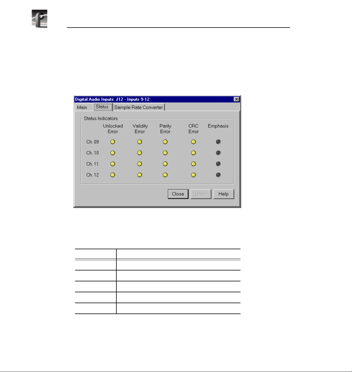
Chapter 2 Using the Profile Configuration Manager
To check the status of digital input channels:
1. In the Digital Audio Input dialog box, click the Status tab. Under Status
Indicators, you see the error status of each channel. If a channel has an error,
the indicator is on. See Table 2 for a description of each error indicator.
2. When you are done checking for errors, click Close or another tab.
Indicator Description
Unlocked Error Receiver unlocked
Validity Error AES receiver validity
Parity Error Parity error
CRC Error CRC subframe errors
Emphasis Detected emphasis
70 Profile Family
Figure 41. Digital Audio Input dialog box, Status tab
Table 2. Digital audio input channel indicators
Page 89
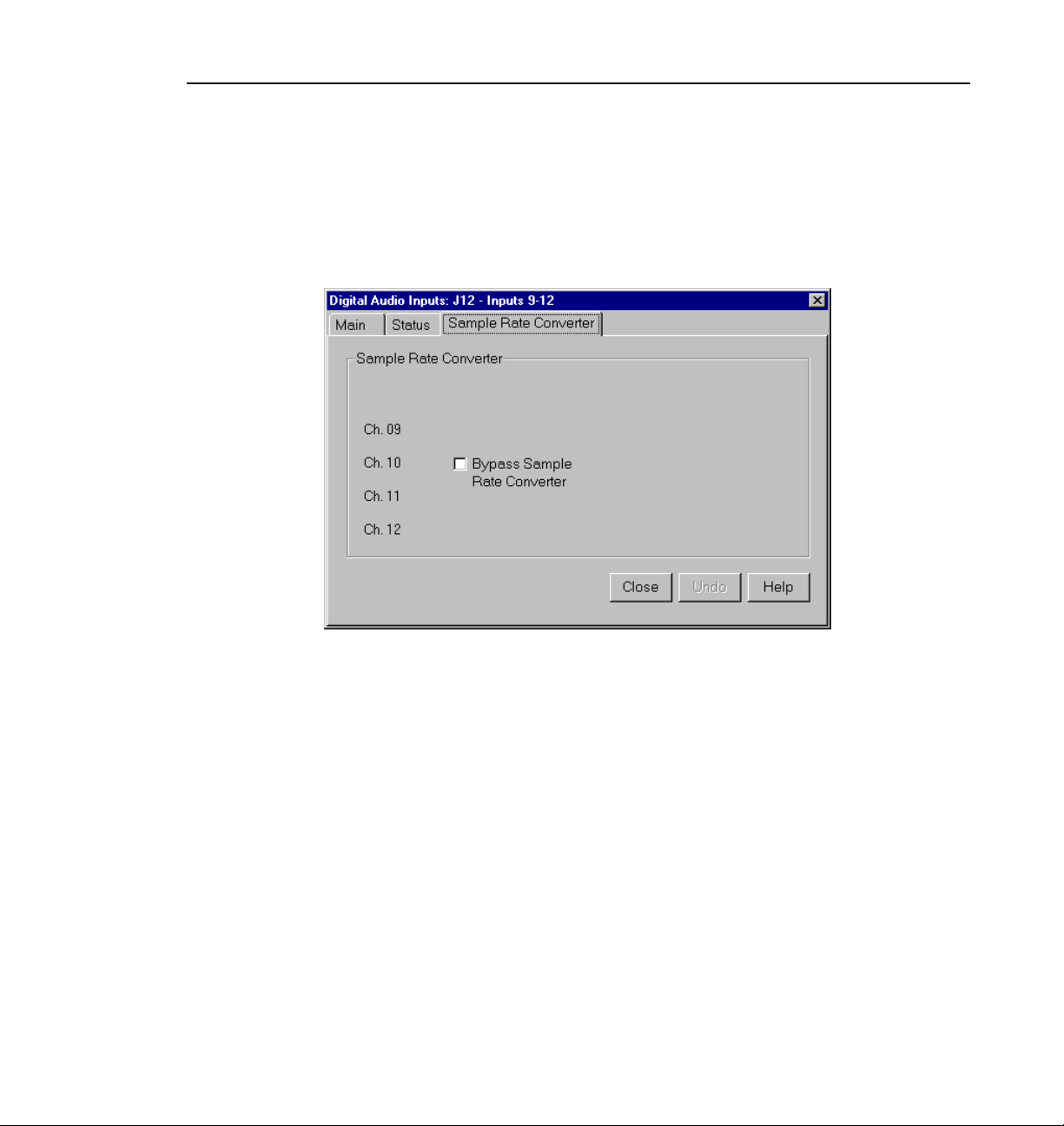
Analog Audio Output
If you want to bypass the sample rate converter:
1. In the Digital Audio Input dialog box, click the Sample Rate Converter tab
(Figure 42). By default, the sample rate converter is enabled. The sample rate
converter affects all four channel inputs.
Figure 42. Digital Audio Input dialog box, Sample Rate Converter tab
2. Click Bypass Sample Rate Converter.
NOTE: Do not bypass sample rate conversion unless you are certain
that all inputs and outputs are synchronous.
3. After you have disabled the sample rate converter, click
Analog Audio Output
In analog audio output, you can change audio channel names, change line
modes for XLR connectors, or adjust individual or group line levels in decibels.
Undo if you want to cancel any changes, or click Help for context-
Click
sensitive Help.
To configure analog audio output:
1. Expand
Audio Output, and then click one of the Analog Channels to bring up
Close or another tab.
Profile Family 71
Page 90

Chapter 2 Using the Profile Configuration Manager
the Analog Audio Output dialog box. The channel numbers on the left refer
to the physical output connectors on the audio output box. Ch. 01 refers to
the first connector, and Ch. 02 refers to the second connector, and so forth.
2. Click the Main tab, if it is not already visible.
3. Click in the box of the output channel whose name you want to change. A
channel name can have up to 30 characters.
4. After you have changed channel name(s), click
72 Profile Family
Figure 43. Analog Audio Output dialog box, Main tab
Close or another tab.
Page 91
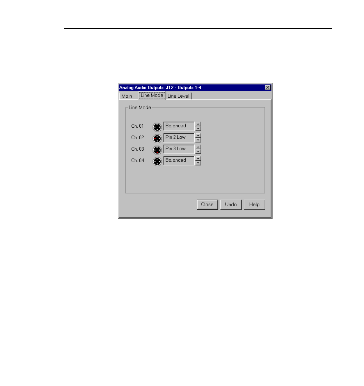
Analog Audio Output
To change line modes for the XLR connectors:
1. In the Analog Audio Output dialog box, click the Line Mode tab (Figure 44).
Figure 44. Analog Audio Output dialog box, Line Mode tab
2. In the Line Mode box, you have three options: Balanced (default),
unbalanced Pin 2 Low, or unbalanced Pin 3 Low. The illustrations of the
XLR connectors to the left of the box give visual cues of the selected mode.
3. After choosing a line mode or modes, click
Close or another tab.
Profile Family 73
Page 92

Chapter 2 Using the Profile Configuration Manager
To trim the line level:
1. In the Analog Audio Output dialog box, click the Line Level tab (Figure 45).
Figure 45. Analog Audio Outputs dialog box, Line Level tab
2. The line level range is –12 to 0 dB. If you trim the line level for an individual
channel with the slider handle, the line level is incremented or decremented
by 1 dB; clicking on either side of the slider handle changes the line level by
0.5 dB. The Level boxes show the current line level. If you enter a number
directly into a Level box, the line level number is rounded to the nearest 0.5
dB.
3. To adjust the trim for all channels at once, use the
Group Fader moves all channels at once, it maintains the individual
the
channel differences.
4. To mute a channel, click the mute button next to the channel name.
5. After you have adjusted the line levels, click
74 Profile Family
Group Fader slider. While
Close or another tab.
Page 93

Digital Audio Output
You can change the names of the digital audio channels. ClickUndo if you want
to cancel any changes. Click
output.
To change a channel name:
1. Expand Audio Output, and then click one of the Digital Channels to bring up
the Digital Audio Output dialog box (Figure 46). The channel numbers on
the left refer to the physical output connectors on the audio output box. Ch.
01 and Ch. 02refer to the channel pair on the first connector, andCh. 03 and
Ch. 04 refer to the pair on the second connector, and so forth.
Digital Audio Output
Help for context-sensitive Help on digital audio
Figure 46. Digital Audio Output dialog box
2. Click in the box of the output channel whose name you want to change. A
channel name can have up to 30 characters.
3. After you have changed the channel name or names, click
Close.
Profile Family 75
Page 94

Chapter 2 Using the Profile Configuration Manager
Audio Configuration for the PDR200
The Audio Configuration dialog box shown in Figure 47 allows you to
configure input and output channels, input clocking, audio quality and monitor
channels.
Input and Output Mapping
The Input Mapping tab is used for mapping input sources to Profile channels,
while the
destinations. For example, you can map Profile Audio Chassis (PAC) input
sources and serial digital audio input sources. Figure 47 and Figure 48 illustrate
a sample configuration: a Profile unit with an audio signal processing board, a
PAC 208 chassis (with A/D and D/A convertors and connectors for eight
channels), and two serial digital cards providing eight analog audio channels,
eight digital audio channels, and four video channels with 16 embedded audio
channels each.
Output Mapping tab is used for mapping Profile channels to output
Figure 47. Audio Configuration dialog box, Input Mapping tab
76 Profile Family
Page 95

Input and Output Mapping
Figure 48. Audio Configuration dialog box, Output Mapping tab
The columns represent the sources to the sixteen channels on the input side and
the destinations from the sixteen channels on the output side. The examples in
Figure 47 and Figure 48 illustrate the system with a PAC 208 chassis allowing
the selection of analog channels 1–8 and digital channels 9–16. A PAC 216
chassis, however, provides sixteen analog inputs and outputs or sixteen digital
inputs and outputs. For the PAC 208, rows 9 through 16 of the analog channel
column, and rows 1 through 8 of the AES/EBU channel column, are crosshatched to indicate that these channels are not selectable. In Figure 48, in the
column labeled AES/EBU, rows 9–16 appear dimmed, indicating that this
audio type is always mapped and cannot be unmapped. Attempting to remap
this section results in an error message.
Profile Family 77
Page 96

Chapter 2 Using the Profile Configuration Manager
The number of columns in the mapping grid depends on the number of possible
input or output audio types that may be mapped to or from the disk recorder
channels. The grid is used for selecting which of the possible input or output
audio sources and destinations to map to the channels. Audio channels are
mapped in groups of four channels only, and the four audio channels are always
mapped to consecutive disk channels. For example, analog channels 1–4 (Input
01–Input 04) in the first column of Figure 47 are mapped to the first four disk
recorder channels (Ch. 01–Ch. 04), while digital channels 9–12 (Input 09–Input
12) in Figure 48 are mapped to another four disk recorder channels (Ch. 09– Ch.
12).
In another example, channels 1–4 may be mapped to analog, channels 5–8
mapped to AES/EBU, and so forth. In addition, analog and AES/EBU audio
types have an assigned one-to-one mapping to their respective channels, that is,
input 1 always maps to channel 1, input 2 to channel 2, and so on.
Serial digital embedded audio contains sixteen audio channels grouped into
four groups of four channels. Each group can be assigned to any group of four
channels. For example, group 1 (Grp1) may be assigned to channels 1–4 (Ch1–
Ch4), 5–8 (Ch5–Ch8), 9–12 (Ch9–Ch12), or 13–16 (Ch13–Ch16). However, a
maximum of two of the four groups from a serial digital video source may be
used simultaneously.
Input Mapping
The Input Mapping tab is used for mapping input channels to Profile disk
channels. The channels must be mapped to an audio type (analog, SDI, or
AES/EBU) at all times—there is no unmapped state for input mapping.
However, channels may only be mapped to one audio type at a time. Analog
and AES/EBU channels must always be mapped directly to the same physical
channel numbers.
To map input channels:
1. Choose
appears (Figure 47).
2. Click the Input Mapping tab.
3. Click on a button in a column. This displays a list containing analog,
AES/EBU, or SDI audio groups. Unavailable audio groups appear dimmed.
78 Profile Family
Options | Audio Configuration. The Audio Configuration dialog box
Page 97

Input Clocking
4. Click on the group of channels you want. Any single group of AES/EBU
channels may be mapped to any group of disk channels.
5. Click
OK to accept your changes or click another tab.
Output Mapping
The Output Mapping tab is used for mapping Profile disk channels to output
destinations. If analog or AES/EBU audio types are present, they are always
mapped to their associated channels. These audio types cannot be unmapped.
Channels may be mapped to multiple audio types, but of these only one can be
a serial digital embedded or SDI audio type.
To map output channels:
1. Choose
appears (Figure 48).
2. Click the Output Mapping tab.
3. Click on a button in a column. This displays a list containing analog,
AES/EBU, or SDI audio groups. Unavailable audio groups appear dimmed.
4. Click on the group of channels you want. The audio channel may be mapped
to any of the outputs in groups of four.
5. Click
OK to accept your changes or click another tab.
Input Clocking
The Input Clocking tab is used for assigning video input clocking sources to
input audio channels. The first column on the left side of the dialog box displays
the disk recorder channel numbers. The last column shows the audio clock
reference source selection (Figure 49).
Options | Audio Configuration. The Audio Configuration dialog box
You get one system reference by default from the Reference Genlock boards,
and up to four video input references, depending on which video boards are
installed in your Profile unit. Even if more than four video references are
available, only the first four input clocking references are used. If you look at
Profile Family 79
Page 98

Chapter 2 Using the Profile Configuration Manager
the bottom of the Configuration Manger window, you will see a graphic
representation of the installed boards. A key to the board representations is
shown in Table 3.
Table 3. Board representation key
Board Tag Board Type
Vid I/O SDI VA Serial digital component video 2
Vid I CAV Component analog video 1
Vid I Cmpst Analog composite video 1
No. of Video
References
The video references shown in the Input Clocking tab—Video Input 1–4 —
correspond to the actual video boards installed, from left to right, as represented
at the bottom of the Configuration Manager window.
For example, a system that does not use all four available clock references
might be configured like this. In this specific example, shown in Table 4, you
have one analog composite board and one component analog board. The panel
in the tab shows System, Video Input 1, and Video Input 2.
Table 4. Configuration example, two video input clocking sources
Board Tag Board Type
Vid I CAV Component analog video 1 Video Input 1
Vid I Cmpst Analog composite video 1 Video Input 2
Board
Reference
Input Clock Reference
80 Profile Family
Page 99
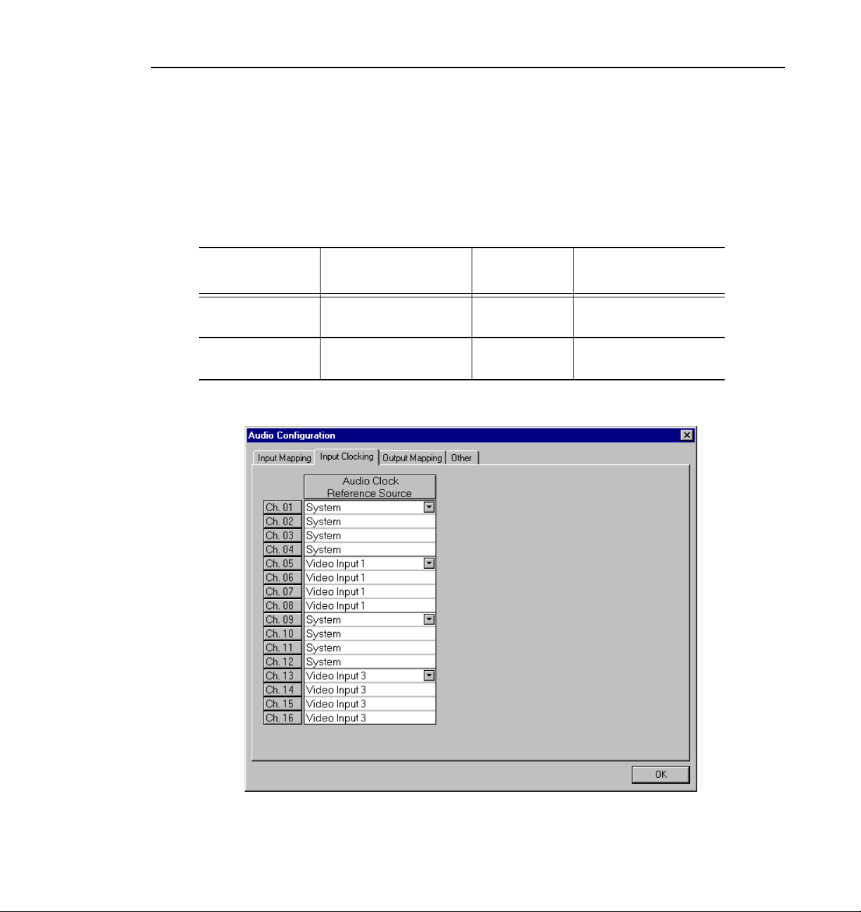
Input Clocking
In the next example, a system that uses all four available clock references might
be configured with two serial digital component boards. In this specific
example, shown in Table 5, the panel in the tab shows System, Video Input 1,
Video Input 2, Video Input 3, and Video Input 4.
Table 5. Configuration example, four video input clocking sources
Board Tag Board Type
Vid I/O SDI VA Serial digital component 1 and 2 Video Input 1,
Vid I/O SDI VA Serial digital component 1 and 2 Video Input 3,
Board
Reference
Input Clock Reference
Video Input 2
Video Input 4
Figure 49. Audio Configuration dialog box, Input Clocking tab
Profile Family 81
Page 100

Chapter 2 Using the Profile Configuration Manager
To change the input clocking:
1. Choose
appears. Click the Input Clocking tab, if it isn’t already displayed.
2. Click the button in the Audio Clock Reference Source column for the desired
channels and select one of up to five choices: System (default) or Video
Input. (The number of video inputs depends on the number of available
video channels.) Selecting one of the video inputs sets the group of four
channels to use the selected input as their audio clocking source.
Options | Audio Configuration. The Audio Configuration dialog box
3. Click
OK to accept your changes or click another tab.
Audio Configuration Other Tab
Finally, under the Other tab, you can select recording and playback quality and
adjust monitor channels.
1. Choose
appears (Figure 50).
Options | Audio Configuration. The Audio Configuration dialog box
82 Profile Family
Figure 50. Audio Configuration dialog box, Other tab
 Loading...