

Page 1
Compact Router
System Configurator
User’s Guide
Miranda Technologies Inc.
3499 Douglas B. Floreani
Montreal, Quebec
Canada H4S 2C6
Page 2

CR Series — CRSC User’s Guide
• Revision: 2.0
• Software Version: 1.6.0
• Part Number: UG0032-03
• Copyright: © 2010 Miranda Technologies. All rights reserved.
• No part of this manual may be reproduced in any form by photocopy, microfilm, xerography or
any other means, or incorporated into any information retrieval system, electronic or mechanical, without the written permission of Miranda Technologies, Inc.
• The information contained in this manual is subject to change without notice or obligation.
• All title and copyrights as well as trade secret, patent and other proprietary rights in and to the
Software Product (including but not limited to any images, photographs, animations, video,
audio, music, test, and “applets” incorporated into the Software Product), the accompanying
printed materials, and any copies of the Software Product, are owned by Miranda Technologies,
Inc. The Software Product is protected by copyright laws and international treaty provisions.
Customer shall not copy the printed materials accompanying the software product.
Notice
The software contains proprietary information of Miranda Technologies, Inc. It is provided under a
license agreement containing restrictions on use and disclosure and is also protected by copyright
law. Reverse engineering of the software is prohibited.
Due to continued product development, the accuracy of the information in this document may
change without notice. The information and intellectual property contained herein is confidential
between Miranda and the client and remains the exclusive property of Miranda. If you find any
problems in the documentation, please report them to us in writing. Miranda does not warrant that
this document is error-free.
FCC Statement
This equipment has been tested and found to comply with the limits for a Class A digital device,
pursuant to part 15 of the FCC Rules. These limits are designed to provide reasonable protection
against harmful interference when the equipment is operated in a commercial environment. This
equipment generates, uses, and can radiate radio frequency energy and, if not installed and used in
accordance with the instruction manual, may cause harmful interference to radio communications.
Operation of this equipment in a residential area is likely to cause harmful interference in which
case the user will be required to correct the interference at his own expense.
Declaration of Conformance (CE)
All of the equipment described in this manual has been designed to conform with the required
safety and emissions standards of the European Community. Products tested and verified to meet
these standards are marked as required by law with the CE mark. (See Symbols and Their Mean-
ings on page v.)
ii Rev 2.0 • 29 Mar 10
Page 3

When shipped into member countries of the European Community, this equipment is accompanied
by authentic copies of original Declarations of Conformance on file in Miranda GVD offices in
Grass Valley, California USA.
Trademarks
Miranda is a registered trademark of Miranda Technologies, Inc.
Brand and product names mentioned in this manual may be trademarks, registered trademarks or
copyrights of their respective holders. All brand and product names mentioned in this manual serve
as comments or examples and are not to be understood as advertising for the products or their manufactures.
Software License Agreement and Warranty Information
Contact Miranda for details on the software license agreement and product warranty.
Technical Support Contact Information
Miranda has made every effort to ensure that the equipment you receive is in perfect working order
and that the equipment fits your needs. In the event that problems arise that you cannot resolve, or
if there are any questions regarding this equipment or information about other products manufactured by Miranda, please contact your local representative or contact Miranda directly through one
of the appropriate means listed here.
• Main telephone: 530-265-1000 (9 am to 9 pm PST)
Fax: 530-265-1021
In the Americas, call toll-free: +1-800-224-7882 (9 am to 9 pm EST)
In Europe, the Middle East, African or the UK, call +44 (0) 1491 820222 (9 am to 6 pm, GMT)
In France, call +33 1 55 86 87 88 (9 am to 5 pm, GMT + 1)
In Asia, call +852-2539-6987 (9 am to 5 pm, GMT + 8)
In China, call +86-10-5873-1814
• Emergency after hours: toll-free: +1-800-224-7882
Tel: +1-514-333-1772
•E-Mail:
In the Americas, support@miranda.com
In Europe, the Middle East, African or the UK, eurotech@miranda.com
In France, eurotech@miranda.com
In Asia, asiatech@miranda.com
In China, asiatech@miranda.com
• Website: http://www.miranda.com
• Mail Shipping
Miranda GVD Miranda GVD
P.O. Box 1658 125 Crown Point Court
Nevada City, CA 95959, USA Grass Valley, CA 95945, USA
Note Return Material Authorization (RMA) required for all returns.
Compact Router System Configurator • User’s Guide iii
Page 4
Change History
The table below lists the changes to the Compact Router User’s Guide.
• User’s Guide Part # UG0032-03
• Software version: 1.6.0
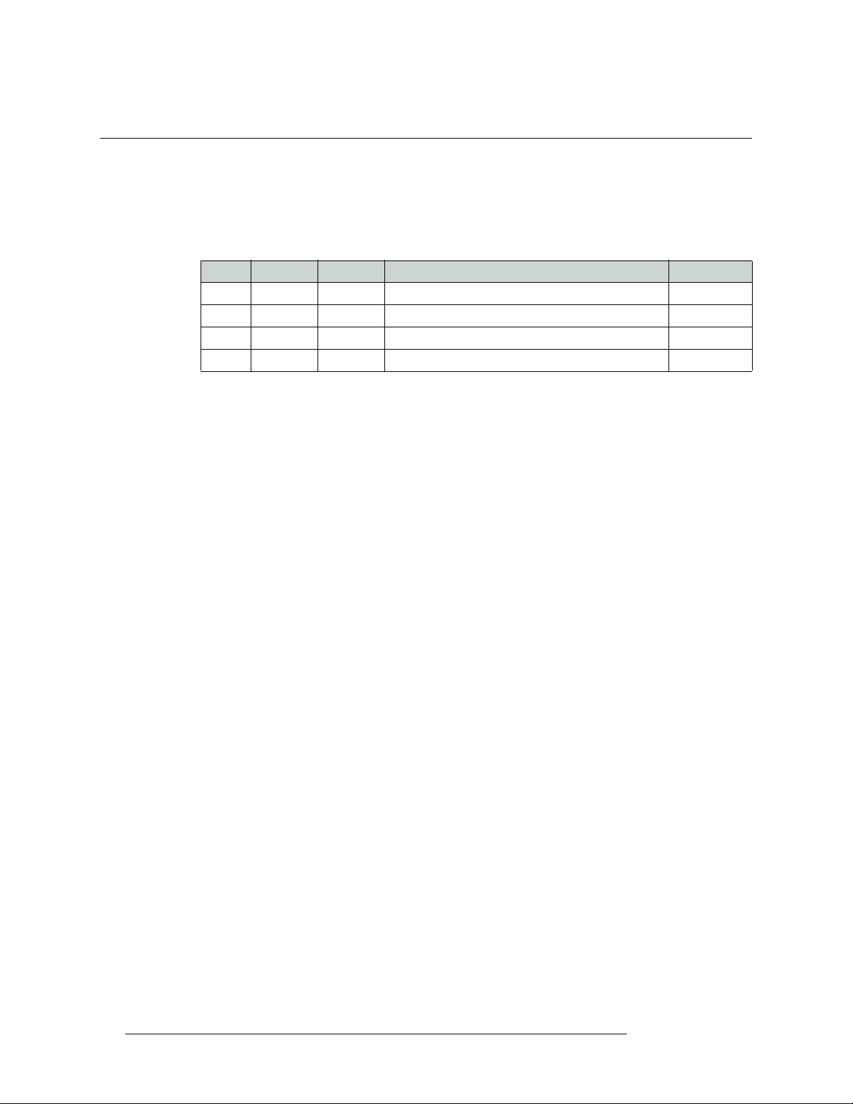
Rev Date ECO Description Approved By
1.0 17 Nov 08 14426 Initial Release D. Cox
1.1 31 Mar 09 15703 New format D.Cox
1.2 12 Oct 09 16114 Restructured online help. New software features DEM
2.0 29 Mar 10 16912 Addition of CQX routers DEM, SM, TS
iv Rev 2.0 • 29 Mar 10
Page 5
Important Safeguards and Notices
This section provides important safety guidelines for operators and service personnel. Specific
warnings and cautions appear throughout the manual where they apply. Please read and follow this
important information, especially those instructions related to the risk of electric shock or injury to
persons.
Warning
Any instructions in this manual that require opening the equipment cover or
enclosure are for use by qualified service personnel only. To reduce the risk of
electric shock, do not perform any service other than that contained in the
operating instructions unless you are qualified to do so.
Symbols and Their Meanings
The lightning flash with arrowhead symbol within an equilateral triangle alerts the user to the presence of dangerous voltages within the product’s enclosure that may be of sufficient magnitude to
constitute a risk of electric shock to persons.
The exclamation point within an equilateral triangle alerts the user to the presence of important
operating and maintenance/service instructions.
The Ground symbol represents a protective grounding terminal. Such a terminal must be connected
to earth ground prior to making any other connections to the equipment.
The fuse symbol indicates that the fuse referenced in the text must be replaced with one having the
ratings indicated.
The presence of this symbol in or on Miranda equipment means that it has been designed, tested
and certified as complying with applicable Underwriter’s Laboratory (USA) regulations and recommendations.
The presence of this symbol in or on Miranda equipment means that it has been designed, tested
and certified as essentially complying with all applicable European Union (CE) regulations and
recommendations.
Compact Router System Configurator • User’s Guide v
Page 6

General Warnings
A warning indicates a possible hazard to personnel which may cause injury or death. Observe the
following general warnings when using or working on this equipment:
• Heed all warnings on the unit and in the operating instructions.
• Do not use this equipment in or near water.
• This equipment is grounded through the grounding conductor of the power cord. To avoid electrical shock, plug the power cord into a properly wired receptacle before connecting the equipment inputs or outputs.
• Route power cords and other cables so they are not likely to be damaged.
• Disconnect power before cleaning the equipment. Do not use liquid or aerosol cleaners; use
only a damp cloth.
• Dangerous voltages may exist at several points in this equipment. To avoid injury, do not touch
exposed connections and components while power is on.
• Do not wear rings or wristwatches when troubleshooting high current circuits such as the power
supplies.
• To avoid fire hazard, use only the specified fuse(s) with the correct type number, voltage and
current ratings as referenced in the appropriate locations in the service instructions or on the
equipment. Always refer fuse replacements to qualified service personnel.
• To avoid explosion, do not operate this equipment in an explosive atmosphere.
• Have qualified service personnel perform safety checks after any service.
General Cautions
A caution indicates a possible hazard to equipment that could result in equipment damage. Observe
the following cautions when operating or working on this equipment:
• When installing this equipment, do not attach the power cord to building surfaces.
• To prevent damage to equipment when replacing fuses, locate and correct the problem that
caused the fuse to blow before re-applying power.
• Use only the specified replacement parts.
• Follow static precautions at all times when handling this equipment.
• This product should only be powered as described in the manual. To prevent equipment damage, select the proper line voltage on the power supply(ies) as described in the installation documentation.
• To prevent damage to the equipment, read the instructions in the equipment manual for proper
input voltage range selection.
• Some master control products include a backup battery. There is a risk of explosion if the battery is replaced by a battery of an incorrect type. Dispose of batteries according to instructions.
• Products that have (1) no on/off switch and (2) use an external power supply must be installed
in proximity to a main power output that is easily accessible.
vi Rev 2.0 • 29 Mar 10
Page 7

Table of Contents
Chapter 1 What Is New. . . . . . . . . . . . . . . . . . . . . . . . . . . . . . . . . . . . . . . . . . . . . . . . . . . . . . . . . . . . . . . 1
Changes . . . . . . . . . . . . . . . . . . . . . . . . . . . . . . . . . . . . . . . . . . . . . . . . . . . . . . . . . . . . . . . . . . . . . . 1
CQX (“Clean and Quiet”) Products . . . . . . . . . . . . . . . . . . . . . . . . . . . . . . . . . . . . . . . . . . . . . 1
New IP Addresses . . . . . . . . . . . . . . . . . . . . . . . . . . . . . . . . . . . . . . . . . . . . . . . . . . . . . . . . . . 1
Persistent IP Addresses and Levels . . . . . . . . . . . . . . . . . . . . . . . . . . . . . . . . . . . . . . . . . . . . . 2
Single Control Panel and Multiple Routers . . . . . . . . . . . . . . . . . . . . . . . . . . . . . . . . . . . . . . . 2
Configurable Remote Panels . . . . . . . . . . . . . . . . . . . . . . . . . . . . . . . . . . . . . . . . . . . . . . . . . . 2
Salvos . . . . . . . . . . . . . . . . . . . . . . . . . . . . . . . . . . . . . . . . . . . . . . . . . . . . . . . . . . . . . . . . . . . . 2
Sources and Destinations No Longer Tied to I/O Position . . . . . . . . . . . . . . . . . . . . . . . . . . . 2
Lock Management and Crosspoint View . . . . . . . . . . . . . . . . . . . . . . . . . . . . . . . . . . . . . . . . . 3
Easy Firmware Updates . . . . . . . . . . . . . . . . . . . . . . . . . . . . . . . . . . . . . . . . . . . . . . . . . . . . . . 3
New Compact Routers Supported . . . . . . . . . . . . . . . . . . . . . . . . . . . . . . . . . . . . . . . . . . . . . . 3
Chapter 2 Before Using CRSC. . . . . . . . . . . . . . . . . . . . . . . . . . . . . . . . . . . . . . . . . . . . . . . . . . . . . . . . . 5
About CRSC . . . . . . . . . . . . . . . . . . . . . . . . . . . . . . . . . . . . . . . . . . . . . . . . . . . . . . . . . . . . . . . . . . 5
Upload Recent Firmware . . . . . . . . . . . . . . . . . . . . . . . . . . . . . . . . . . . . . . . . . . . . . . . . . . . . . . . . . 6
Panel Locked at Reset . . . . . . . . . . . . . . . . . . . . . . . . . . . . . . . . . . . . . . . . . . . . . . . . . . . . . . . . . . . 7
System Design . . . . . . . . . . . . . . . . . . . . . . . . . . . . . . . . . . . . . . . . . . . . . . . . . . . . . . . . . . . . . . . . . 7
Design Issues . . . . . . . . . . . . . . . . . . . . . . . . . . . . . . . . . . . . . . . . . . . . . . . . . . . . . . . . . . . . . . 7
Creating a Network . . . . . . . . . . . . . . . . . . . . . . . . . . . . . . . . . . . . . . . . . . . . . . . . . . . . . . . . . . . . . 8
What is a Subnet?. . . . . . . . . . . . . . . . . . . . . . . . . . . . . . . . . . . . . . . . . . . . . . . . . . . . . . . . . . . 9
What is a Subnet Mask?. . . . . . . . . . . . . . . . . . . . . . . . . . . . . . . . . . . . . . . . . . . . . . . . . . . . . . 9
What is an IP Address? . . . . . . . . . . . . . . . . . . . . . . . . . . . . . . . . . . . . . . . . . . . . . . . . . . . . . . 9
Rotary Switches . . . . . . . . . . . . . . . . . . . . . . . . . . . . . . . . . . . . . . . . . . . . . . . . . . . . . . . 10
Initial Assembly . . . . . . . . . . . . . . . . . . . . . . . . . . . . . . . . . . . . . . . . . . . . . . . . . . . . . . . 10
Powering Up Re-initializes . . . . . . . . . . . . . . . . . . . . . . . . . . . . . . . . . . . . . . . . . . . . . . 10
Network Speeds . . . . . . . . . . . . . . . . . . . . . . . . . . . . . . . . . . . . . . . . . . . . . . . . . . . . . . . . . . . 11
Cabling . . . . . . . . . . . . . . . . . . . . . . . . . . . . . . . . . . . . . . . . . . . . . . . . . . . . . . . . . . . . . . . . . . 11
CQX Networks. . . . . . . . . . . . . . . . . . . . . . . . . . . . . . . . . . . . . . . . . . . . . . . . . . . . . . . . . . . . 11
Mode Rotary Switch . . . . . . . . . . . . . . . . . . . . . . . . . . . . . . . . . . . . . . . . . . . . . . . . . . . 11
Frame ID Rotary Switch . . . . . . . . . . . . . . . . . . . . . . . . . . . . . . . . . . . . . . . . . . . . . . . . 12
Setting Up the Configuration PC and Installing CRSC . . . . . . . . . . . . . . . . . . . . . . . . . . . . . . . . . 12
How to Configure your PC’s IP Address. . . . . . . . . . . . . . . . . . . . . . . . . . . . . . . . . . . . . . . . 13
How to Create Multiple Subnets . . . . . . . . . . . . . . . . . . . . . . . . . . . . . . . . . . . . . . . . . . 15
How to Install CRSC . . . . . . . . . . . . . . . . . . . . . . . . . . . . . . . . . . . . . . . . . . . . . . . . . . . . . . . 16
Installation Testing. . . . . . . . . . . . . . . . . . . . . . . . . . . . . . . . . . . . . . . . . . . . . . . . . . . . . . . . . . . . . 16
Chapter 3 Show Products Online . . . . . . . . . . . . . . . . . . . . . . . . . . . . . . . . . . . . . . . . . . . . . . . . . . . .17
Chapter 4 CR Series Ethernet Setttings. . . . . . . . . . . . . . . . . . . . . . . . . . . . . . . . . . . . . . . . . . . . . . .19
CQX Routers — Separate Subnet. . . . . . . . . . . . . . . . . . . . . . . . . . . . . . . . . . . . . . . . . . . . . . 19
An Overview of Networking . . . . . . . . . . . . . . . . . . . . . . . . . . . . . . . . . . . . . . . . . . . . . . . . . . . . . 19
Using the ‘CR Series Ethernet Settings’ Page . . . . . . . . . . . . . . . . . . . . . . . . . . . . . . . . . . . . 20
How to Add Routers to a Network. . . . . . . . . . . . . . . . . . . . . . . . . . . . . . . . . . . . . . . . . . . . . 20
How to Add Remote Panels to a Network . . . . . . . . . . . . . . . . . . . . . . . . . . . . . . . . . . . . . . . 21
How to Change Ethernet Settings . . . . . . . . . . . . . . . . . . . . . . . . . . . . . . . . . . . . . . . . . . . . . 22
Compact Router System Configurator • User’s Guide vii
Page 8

Table of Contents
Chapter 5 Configuring Router Levels . . . . . . . . . . . . . . . . . . . . . . . . . . . . . . . . . . . . . . . . . . . . . . . . 25
Overview . . . . . . . . . . . . . . . . . . . . . . . . . . . . . . . . . . . . . . . . . . . . . . . . . . . . . . . . . . . . . . . . . . . . 25
Levels and Partitions . . . . . . . . . . . . . . . . . . . . . . . . . . . . . . . . . . . . . . . . . . . . . . . . . . . . . . . 25
Using the ‘Configure Router Levels’ Page . . . . . . . . . . . . . . . . . . . . . . . . . . . . . . . . . . . . . . 26
Active Subnet . . . . . . . . . . . . . . . . . . . . . . . . . . . . . . . . . . . . . . . . . . . . . . . . . . . . . . . . . 27
Signal Types. . . . . . . . . . . . . . . . . . . . . . . . . . . . . . . . . . . . . . . . . . . . . . . . . . . . . . . . . . 28
How to Create or Update a Level. . . . . . . . . . . . . . . . . . . . . . . . . . . . . . . . . . . . . . . . . . . . . . 28
How to Create Multiple Levels . . . . . . . . . . . . . . . . . . . . . . . . . . . . . . . . . . . . . . . . . . . . . . . 29
How to Delete a Level . . . . . . . . . . . . . . . . . . . . . . . . . . . . . . . . . . . . . . . . . . . . . . . . . . . . . . 29
Chapter 6 Setting Up Machine Control Routers . . . . . . . . . . . . . . . . . . . . . . . . . . . . . . . . . . . . . . 31
An Overview of Machine Control Routers . . . . . . . . . . . . . . . . . . . . . . . . . . . . . . . . . . . . . . . . . . 31
Viewing Machine Control Router Crosspoints . . . . . . . . . . . . . . . . . . . . . . . . . . . . . . . . . . . 32
Machine Control Router Port Types . . . . . . . . . . . . . . . . . . . . . . . . . . . . . . . . . . . . . . . . . . . 32
Using the ‘Setup Machine Control Router’ Page. . . . . . . . . . . . . . . . . . . . . . . . . . . . . . . . . . 34
How to Select a Machine Control Router . . . . . . . . . . . . . . . . . . . . . . . . . . . . . . . . . . . . . . . 35
How to Change a Port Type . . . . . . . . . . . . . . . . . . . . . . . . . . . . . . . . . . . . . . . . . . . . . . . . . . 36
Chapter 7 Programming Remote Panels . . . . . . . . . . . . . . . . . . . . . . . . . . . . . . . . . . . . . . . . . . . . .37
Overview . . . . . . . . . . . . . . . . . . . . . . . . . . . . . . . . . . . . . . . . . . . . . . . . . . . . . . . . . . . . . . . . . . . . 37
Configuring Remote Panels . . . . . . . . . . . . . . . . . . . . . . . . . . . . . . . . . . . . . . . . . . . . . . . . . . 37
“Captive” Panels . . . . . . . . . . . . . . . . . . . . . . . . . . . . . . . . . . . . . . . . . . . . . . . . . . . . . . . . . . 38
Standard Mode . . . . . . . . . . . . . . . . . . . . . . . . . . . . . . . . . . . . . . . . . . . . . . . . . . . . . . . . 38
Enhanced Mode (Hold and No-hold) . . . . . . . . . . . . . . . . . . . . . . . . . . . . . . . . . . . . . . . 39
About Salvos . . . . . . . . . . . . . . . . . . . . . . . . . . . . . . . . . . . . . . . . . . . . . . . . . . . . . . . . . . . . . 39
Using the ‘Program Remote Panels’ Page . . . . . . . . . . . . . . . . . . . . . . . . . . . . . . . . . . . . . . . 40
Button Functions . . . . . . . . . . . . . . . . . . . . . . . . . . . . . . . . . . . . . . . . . . . . . . . . . . . . . . . . . . 42
Destination . . . . . . . . . . . . . . . . . . . . . . . . . . . . . . . . . . . . . . . . . . . . . . . . . . . . . . . . . . . 42
Levels . . . . . . . . . . . . . . . . . . . . . . . . . . . . . . . . . . . . . . . . . . . . . . . . . . . . . . . . . . . . . . . 43
Salvos . . . . . . . . . . . . . . . . . . . . . . . . . . . . . . . . . . . . . . . . . . . . . . . . . . . . . . . . . . . . . . . 43
Sources . . . . . . . . . . . . . . . . . . . . . . . . . . . . . . . . . . . . . . . . . . . . . . . . . . . . . . . . . . . . . . 44
Unused . . . . . . . . . . . . . . . . . . . . . . . . . . . . . . . . . . . . . . . . . . . . . . . . . . . . . . . . . . . . . . 45
How to View an Existing Panel Configuration . . . . . . . . . . . . . . . . . . . . . . . . . . . . . . . . . . . 45
How to Create a New Panel Configuration . . . . . . . . . . . . . . . . . . . . . . . . . . . . . . . . . . . . . . 45
How to Change a Button Function. . . . . . . . . . . . . . . . . . . . . . . . . . . . . . . . . . . . . . . . . . . . . 46
How to Change a Button Label . . . . . . . . . . . . . . . . . . . . . . . . . . . . . . . . . . . . . . . . . . . . . . . 47
How to Change the Panel Operation Mode . . . . . . . . . . . . . . . . . . . . . . . . . . . . . . . . . . . . . . 48
Chapter 8 Viewing Router Crosspoints. . . . . . . . . . . . . . . . . . . . . . . . . . . . . . . . . . . . . . . . . . . . . . .49
Discussion . . . . . . . . . . . . . . . . . . . . . . . . . . . . . . . . . . . . . . . . . . . . . . . . . . . . . . . . . . . . . . . . . . . 49
About AES Crosspoints . . . . . . . . . . . . . . . . . . . . . . . . . . . . . . . . . . . . . . . . . . . . . . . . . . . . . 49
Using the ‘View Router Crosspoints’ Page . . . . . . . . . . . . . . . . . . . . . . . . . . . . . . . . . . . . . . 50
How to View an Existing Panel Crosspoint Configuration . . . . . . . . . . . . . . . . . . . . . . . . . . 51
How to Perform or Undo a Take . . . . . . . . . . . . . . . . . . . . . . . . . . . . . . . . . . . . . . . . . . . . . . 51
Chapter 9 Firmware Updates . . . . . . . . . . . . . . . . . . . . . . . . . . . . . . . . . . . . . . . . . . . . . . . . . . . . . . . . 53
Discussion . . . . . . . . . . . . . . . . . . . . . . . . . . . . . . . . . . . . . . . . . . . . . . . . . . . . . . . . . . . . . . . . . . . 53
Using the ‘Firmware Updates’ Page . . . . . . . . . . . . . . . . . . . . . . . . . . . . . . . . . . . . . . . . . . . 53
How to Update Firmware. . . . . . . . . . . . . . . . . . . . . . . . . . . . . . . . . . . . . . . . . . . . . . . . . . . . 54
How to View Past Update Reports . . . . . . . . . . . . . . . . . . . . . . . . . . . . . . . . . . . . . . . . . . . . 55
How to Reset Frames . . . . . . . . . . . . . . . . . . . . . . . . . . . . . . . . . . . . . . . . . . . . . . . . . . . . . . . 56
viii Rev 1.1 • 29 Mar 10
Page 9

Table of Contents
Chapter 10 Lock Maintenance . . . . . . . . . . . . . . . . . . . . . . . . . . . . . . . . . . . . . . . . . . . . . . . . . . . . . . . . 57
Discussion . . . . . . . . . . . . . . . . . . . . . . . . . . . . . . . . . . . . . . . . . . . . . . . . . . . . . . . . . . . . . . . . . . . 57
Using the ‘Lock Maintenance’ Page . . . . . . . . . . . . . . . . . . . . . . . . . . . . . . . . . . . . . . . . . . . 57
How to Unlock an Individual or All Locks . . . . . . . . . . . . . . . . . . . . . . . . . . . . . . . . . . . . . . 58
Chapter 11 Setup NV9000 Remote Panel. . . . . . . . . . . . . . . . . . . . . . . . . . . . . . . . . . . . . . . . . . . . . . 59
Discussion . . . . . . . . . . . . . . . . . . . . . . . . . . . . . . . . . . . . . . . . . . . . . . . . . . . . . . . . . . . . . . . . . . . 59
Using the ‘Setup NV9000 Remote Panel’ Page. . . . . . . . . . . . . . . . . . . . . . . . . . . . . . . . . . . 59
How to Setup an NV9000 Remote Panel. . . . . . . . . . . . . . . . . . . . . . . . . . . . . . . . . . . . . . . . 61
How to Disable NV9000 Control. . . . . . . . . . . . . . . . . . . . . . . . . . . . . . . . . . . . . . . . . . . . . . 61
Chapter 12 Tutorials . . . . . . . . . . . . . . . . . . . . . . . . . . . . . . . . . . . . . . . . . . . . . . . . . . . . . . . . . . . . . . . . . 63
Routing Overview . . . . . . . . . . . . . . . . . . . . . . . . . . . . . . . . . . . . . . . . . . . . . . . . . . . . . . . . . . . . . 63
What is a Router? . . . . . . . . . . . . . . . . . . . . . . . . . . . . . . . . . . . . . . . . . . . . . . . . . . . . . . . . . . 63
Inside the Router . . . . . . . . . . . . . . . . . . . . . . . . . . . . . . . . . . . . . . . . . . . . . . . . . . . . . . 64
Sources and Destinations . . . . . . . . . . . . . . . . . . . . . . . . . . . . . . . . . . . . . . . . . . . . . . . . 65
What is a Control Panel? . . . . . . . . . . . . . . . . . . . . . . . . . . . . . . . . . . . . . . . . . . . . . . . . . . . . 65
Signals . . . . . . . . . . . . . . . . . . . . . . . . . . . . . . . . . . . . . . . . . . . . . . . . . . . . . . . . . . . . . . . . . . 65
A Note About AES Signal Types . . . . . . . . . . . . . . . . . . . . . . . . . . . . . . . . . . . . . . . . . 66
A Note About Machine Control Signals . . . . . . . . . . . . . . . . . . . . . . . . . . . . . . . . . . . . 66
Partitions and Levels . . . . . . . . . . . . . . . . . . . . . . . . . . . . . . . . . . . . . . . . . . . . . . . . . . . . . . . 67
Router Control . . . . . . . . . . . . . . . . . . . . . . . . . . . . . . . . . . . . . . . . . . . . . . . . . . . . . . . . . . . . 67
Remote Panel Operating Modes. . . . . . . . . . . . . . . . . . . . . . . . . . . . . . . . . . . . . . . . . . . . . . . . . . . 68
Standard Mode . . . . . . . . . . . . . . . . . . . . . . . . . . . . . . . . . . . . . . . . . . . . . . . . . . . . . . . . . . . . 68
Enhanced Mode . . . . . . . . . . . . . . . . . . . . . . . . . . . . . . . . . . . . . . . . . . . . . . . . . . . . . . . . . . . 68
Salvos . . . . . . . . . . . . . . . . . . . . . . . . . . . . . . . . . . . . . . . . . . . . . . . . . . . . . . . . . . . . . . . . . . . . . . . 69
Cabling . . . . . . . . . . . . . . . . . . . . . . . . . . . . . . . . . . . . . . . . . . . . . . . . . . . . . . . . . . . . . . . . . . . . . . 69
Cable Types . . . . . . . . . . . . . . . . . . . . . . . . . . . . . . . . . . . . . . . . . . . . . . . . . . . . . . . . . . . . . . 70
Connectors . . . . . . . . . . . . . . . . . . . . . . . . . . . . . . . . . . . . . . . . . . . . . . . . . . . . . . . . . . . . . . . 70
Serial Connector. . . . . . . . . . . . . . . . . . . . . . . . . . . . . . . . . . . . . . . . . . . . . . . . . . . . . . . 70
DB25 Connectors. . . . . . . . . . . . . . . . . . . . . . . . . . . . . . . . . . . . . . . . . . . . . . . . . . . . . . 71
RJ-45 Connectors. . . . . . . . . . . . . . . . . . . . . . . . . . . . . . . . . . . . . . . . . . . . . . . . . . . . . . 71
Making Connections . . . . . . . . . . . . . . . . . . . . . . . . . . . . . . . . . . . . . . . . . . . . . . . . . . . . . . . 71
Sample Configuration . . . . . . . . . . . . . . . . . . . . . . . . . . . . . . . . . . . . . . . . . . . . . . . . . . . . . . 72
Equipment . . . . . . . . . . . . . . . . . . . . . . . . . . . . . . . . . . . . . . . . . . . . . . . . . . . . . . . . . . . 72
Analysis . . . . . . . . . . . . . . . . . . . . . . . . . . . . . . . . . . . . . . . . . . . . . . . . . . . . . . . . . . . . . 72
Partitioning. . . . . . . . . . . . . . . . . . . . . . . . . . . . . . . . . . . . . . . . . . . . . . . . . . . . . . . . . . . 73
Operational Considerations . . . . . . . . . . . . . . . . . . . . . . . . . . . . . . . . . . . . . . . . . . . . . . 75
Cabling Diagram . . . . . . . . . . . . . . . . . . . . . . . . . . . . . . . . . . . . . . . . . . . . . . . . . . . . . . 75
Products . . . . . . . . . . . . . . . . . . . . . . . . . . . . . . . . . . . . . . . . . . . . . . . . . . . . . . . . . . . . . . . . . . . . . 77
Summary . . . . . . . . . . . . . . . . . . . . . . . . . . . . . . . . . . . . . . . . . . . . . . . . . . . . . . . . . . . . . . . . 77
Routers . . . . . . . . . . . . . . . . . . . . . . . . . . . . . . . . . . . . . . . . . . . . . . . . . . . . . . . . . . . . . . . . . . 78
Control Panels . . . . . . . . . . . . . . . . . . . . . . . . . . . . . . . . . . . . . . . . . . . . . . . . . . . . . . . . . . . . 79
Remote Panel Modules . . . . . . . . . . . . . . . . . . . . . . . . . . . . . . . . . . . . . . . . . . . . . . . . . . . . . 79
Usage . . . . . . . . . . . . . . . . . . . . . . . . . . . . . . . . . . . . . . . . . . . . . . . . . . . . . . . . . . . . . . . . . . . 79
Software . . . . . . . . . . . . . . . . . . . . . . . . . . . . . . . . . . . . . . . . . . . . . . . . . . . . . . . . . . . . . . . . . 81
Benefits . . . . . . . . . . . . . . . . . . . . . . . . . . . . . . . . . . . . . . . . . . . . . . . . . . . . . . . . . . . . . . . . . 81
The Routers . . . . . . . . . . . . . . . . . . . . . . . . . . . . . . . . . . . . . . . . . . . . . . . . . . . . . . . . . . . . . . 81
Digital Video Routers . . . . . . . . . . . . . . . . . . . . . . . . . . . . . . . . . . . . . . . . . . . . . . . . . . 83
3Gig Video Routers . . . . . . . . . . . . . . . . . . . . . . . . . . . . . . . . . . . . . . . . . . . . . . . . . . . 84
HD Video Routers . . . . . . . . . . . . . . . . . . . . . . . . . . . . . . . . . . . . . . . . . . . . . . . . . . . . . 84
SD Video Routers . . . . . . . . . . . . . . . . . . . . . . . . . . . . . . . . . . . . . . . . . . . . . . . . . . . . . 84
NR Video Routers . . . . . . . . . . . . . . . . . . . . . . . . . . . . . . . . . . . . . . . . . . . . . . . . . . . . . 84
CQX Video Routers . . . . . . . . . . . . . . . . . . . . . . . . . . . . . . . . . . . . . . . . . . . . . . . . . . . 84
Analog Video Routers . . . . . . . . . . . . . . . . . . . . . . . . . . . . . . . . . . . . . . . . . . . . . . . . . . 86
Compact Router System Configurator • User’s Guide ix
Page 10

Table of Contents
Digital Audio Routers . . . . . . . . . . . . . . . . . . . . . . . . . . . . . . . . . . . . . . . . . . . . . . . . . . 86
Analog Audio Routers . . . . . . . . . . . . . . . . . . . . . . . . . . . . . . . . . . . . . . . . . . . . . . . . . 88
Machine Control Routers . . . . . . . . . . . . . . . . . . . . . . . . . . . . . . . . . . . . . . . . . . . . . . . 88
Background Information . . . . . . . . . . . . . . . . . . . . . . . . . . . . . . . . . . . . . . . . . . . . . . . . 89
Controlling or Controlled. . . . . . . . . . . . . . . . . . . . . . . . . . . . . . . . . . . . . . . . . . . . . . . . 89
Dynamic . . . . . . . . . . . . . . . . . . . . . . . . . . . . . . . . . . . . . . . . . . . . . . . . . . . . . . . . . . . . . 89
Master or Slave . . . . . . . . . . . . . . . . . . . . . . . . . . . . . . . . . . . . . . . . . . . . . . . . . . . . . . . 89
Configuration . . . . . . . . . . . . . . . . . . . . . . . . . . . . . . . . . . . . . . . . . . . . . . . . . . . . . . . . . 90
The Control Panels . . . . . . . . . . . . . . . . . . . . . . . . . . . . . . . . . . . . . . . . . . . . . . . . . . . . . . . . . 90
1RU Panels. . . . . . . . . . . . . . . . . . . . . . . . . . . . . . . . . . . . . . . . . . . . . . . . . . . . . . . . . . . 90
CQX Panel . . . . . . . . . . . . . . . . . . . . . . . . . . . . . . . . . . . . . . . . . . . . . . . . . . . . . . . . . . . 90
2RU Panels. . . . . . . . . . . . . . . . . . . . . . . . . . . . . . . . . . . . . . . . . . . . . . . . . . . . . . . . . . . 91
The Remote Panel Modules . . . . . . . . . . . . . . . . . . . . . . . . . . . . . . . . . . . . . . . . . . . . . . . . . . 92
Chapter 13 Operating Panels . . . . . . . . . . . . . . . . . . . . . . . . . . . . . . . . . . . . . . . . . . . . . . . . . . . . . . . . . 93
Control Panel Buttons . . . . . . . . . . . . . . . . . . . . . . . . . . . . . . . . . . . . . . . . . . . . . . . . . . . . . . . . . . 93
Button Types . . . . . . . . . . . . . . . . . . . . . . . . . . . . . . . . . . . . . . . . . . . . . . . . . . . . . . . . . 94
Panel Modes . . . . . . . . . . . . . . . . . . . . . . . . . . . . . . . . . . . . . . . . . . . . . . . . . . . . . . . . . . 94
Red Buttons . . . . . . . . . . . . . . . . . . . . . . . . . . . . . . . . . . . . . . . . . . . . . . . . . . . . . . . . . . 95
Button Order . . . . . . . . . . . . . . . . . . . . . . . . . . . . . . . . . . . . . . . . . . . . . . . . . . . . . . . . . . . . . 95
Spatial Ordering . . . . . . . . . . . . . . . . . . . . . . . . . . . . . . . . . . . . . . . . . . . . . . . . . . . . . . 95
Temporal Ordering . . . . . . . . . . . . . . . . . . . . . . . . . . . . . . . . . . . . . . . . . . . . . . . . . . . . 95
Button Illumination . . . . . . . . . . . . . . . . . . . . . . . . . . . . . . . . . . . . . . . . . . . . . . . . . . . . . . . . 95
Source Button Lighting . . . . . . . . . . . . . . . . . . . . . . . . . . . . . . . . . . . . . . . . . . . . . . . . . 96
Destination Button Lighting. . . . . . . . . . . . . . . . . . . . . . . . . . . . . . . . . . . . . . . . . . . . . . 96
Level Button Lighting . . . . . . . . . . . . . . . . . . . . . . . . . . . . . . . . . . . . . . . . . . . . . . . . . . 96
CQX Panel Buttons . . . . . . . . . . . . . . . . . . . . . . . . . . . . . . . . . . . . . . . . . . . . . . . . . . . . . . . . 97
Power Up and Reset . . . . . . . . . . . . . . . . . . . . . . . . . . . . . . . . . . . . . . . . . . . . . . . . . . . . . . . . . . . . 98
During System Construction . . . . . . . . . . . . . . . . . . . . . . . . . . . . . . . . . . . . . . . . . . . . . . . . . 98
Routers at Power-Up . . . . . . . . . . . . . . . . . . . . . . . . . . . . . . . . . . . . . . . . . . . . . . . . . . . . . . . 98
Remote Panel Modules at Power-Up . . . . . . . . . . . . . . . . . . . . . . . . . . . . . . . . . . . . . . . . . . . 98
Performing Takes . . . . . . . . . . . . . . . . . . . . . . . . . . . . . . . . . . . . . . . . . . . . . . . . . . . . . . . . . . . . . . 99
Normal Takes . . . . . . . . . . . . . . . . . . . . . . . . . . . . . . . . . . . . . . . . . . . . . . . . . . . . . . . . . . . . . 99
Example
Example
Breakaway Takes . . . . . . . . . . . . . . . . . . . . . . . . . . . . . . . . . . . . . . . . . . . . . . . . . . . . . . . . . 100
Example
Example
Example
Example — Breakaway in Enhanced Mode with Hold . . . . . . . . . . . . . . . . . . . . . . . . 103
CP3201 Takes . . . . . . . . . . . . . . . . . . . . . . . . . . . . . . . . . . . . . . . . . . . . . . . . . . . . . . . . . . . 104
Example
Example
Example
Example
Machine Control Takes . . . . . . . . . . . . . . . . . . . . . . . . . . . . . . . . . . . . . . . . . . . . . . . . . . . . 106
CQX Takes. . . . . . . . . . . . . . . . . . . . . . . . . . . . . . . . . . . . . . . . . . . . . . . . . . . . . . . . . . . . . . 107
Performing Locks. . . . . . . . . . . . . . . . . . . . . . . . . . . . . . . . . . . . . . . . . . . . . . . . . . . . . . . . . . . . . 107
Panel Lock . . . . . . . . . . . . . . . . . . . . . . . . . . . . . . . . . . . . . . . . . . . . . . . . . . . . . . . . . . . . . . 107
Destination Locks . . . . . . . . . . . . . . . . . . . . . . . . . . . . . . . . . . . . . . . . . . . . . . . . . . . . . . . . 107
Simple Locks . . . . . . . . . . . . . . . . . . . . . . . . . . . . . . . . . . . . . . . . . . . . . . . . . . . . . . . . 108
Complex Locks . . . . . . . . . . . . . . . . . . . . . . . . . . . . . . . . . . . . . . . . . . . . . . . . . . . . . . 108
CP3201 Locks and Unlocks. . . . . . . . . . . . . . . . . . . . . . . . . . . . . . . . . . . . . . . . . . . . . 108
Executing Salvos . . . . . . . . . . . . . . . . . . . . . . . . . . . . . . . . . . . . . . . . . . . . . . . . . . . . . . . . . . . . . 109
— Normal Take in Standard Mode . . . . . . . . . . . . . . . . . . . . . . . . . . . . . . . . . 99
— Normal Take in Enhanced Mode . . . . . . . . . . . . . . . . . . . . . . . . . . . . . . . 100
— Breakaway in Standard Mode. . . . . . . . . . . . . . . . . . . . . . . . . . . . . . . . . . 100
— Breakaway in Enhanced Mode without Hold — Variant 1. . . . . . . . . . . . 101
— Breakaway in Enhanced Mode without Hold — Variant 2. . . . . . . . . . . . 102
— Normal Take for CP3201 . . . . . . . . . . . . . . . . . . . . . . . . . . . . . . . . . . . . . 104
— Breakaway for CP3201 in Standard Mode . . . . . . . . . . . . . . . . . . . . . . . . 104
— Breakaway for CP3201 in Enhanced Mode with Hold . . . . . . . . . . . . . . 105
— Breakaway Take for CP3201 in Enhanced Mode without Hold . . . . . . . 105
x Rev 1.1 • 29 Mar 10
Page 11

Table of Contents
Performing Level Selection . . . . . . . . . . . . . . . . . . . . . . . . . . . . . . . . . . . . . . . . . . . . . . . . . . . . . 109
Level Selection in Standard Mode . . . . . . . . . . . . . . . . . . . . . . . . . . . . . . . . . . . . . . . . . . . . 110
Button Order . . . . . . . . . . . . . . . . . . . . . . . . . . . . . . . . . . . . . . . . . . . . . . . . . . . . . . . . 110
Level Selection in Enhanced Mode . . . . . . . . . . . . . . . . . . . . . . . . . . . . . . . . . . . . . . . . . . . 112
Chapter 14 Glossary. . . . . . . . . . . . . . . . . . . . . . . . . . . . . . . . . . . . . . . . . . . . . . . . . . . . . . . . . . . . . . . . .113
Index . . . . . . . . . . . . . . . . . . . . . . . . . . . . . . . . . . . . . . . . . . . . . . . . . . . . . . . . . . . . . . . . . . . . . . . . .115
Compact Router System Configurator • User’s Guide xi
Page 12

Table of Contents
xii Rev 1.1 • 29 Mar 10
Page 13

1. What Is New
Before using the Compact Router System Configurator (CRSC), please review the following list of
feature enhancements and system changes.
Changes
CQX (“Clean and Quiet”) Products
CRSC supports the new CQX (“clean and quiet”) router and CQX control panel. The CQX router
and CQX panel are designed to work together as a single unit and are not usable as a separate router
or panel at this time.
A CQX router performs smooth transitions in both HD and SD video and audio. The CQX control
panel has 4 dedicated transition type buttons (cut, v-fade, cut-fade, and fade-cut). Transitions may
be slow (3 seconds), medium (2 seconds) or fast (1 second). The number of frames used for a transition depends on the video frame rate, as follows:
• 1080i59.94, NTSC
• 1080i50, PAL
• 720p50
• 720p60
— slow 150, medium 100, fast 50.
— slow 180, medium 120, fast 60.
— slow 90, medium 60, fast 30.
— slow 75, medium 50, fast 25.
A CQX router operates only with a CQX control panel. The CQX panel can be local (mounted on a
CQX router) or it can be remote (mounted on a remote panel module). The remote CQX panel must
be connected to the CQX router by an Ethernet switch. However, the transition rate or transition
type buttons of a CQX control panel mounted on a remote panel module do not operate.
All CQX routers and control panels must exist on a separate subnet from other CR Series products.
For more information, see CR Series Ethernet Setttings
on page 19.
New IP Addresses
The default IP address for routers and remote control panels have been changed. Previously, the
default IP addresses were:
Routers
Remote Panel Modules
The current default IP addresses are now:
Routers
Remote Panel Modules
(xxx.yyy.zzz denotes the subnet determined by the router or remote panel module. The default
is 192.168.2.).
For instructions on managing IP addresses, see Chapter 4.
— 192.168.x where x= the switch setting plus 20.
— 192.168.x where x = the switch setting plus 24.
— 192.168.x where x = the switch setting plus 100.
— 192.168.x where x = the switch setting plus 50.
Compact Router System Configurator • User’s Guide 1
Page 14

1. What Is New
Changes
Persistent IP Addresses and Levels
After routers and remote panels are configured for your network, IP addresses and levels are no
longer associated with rotary switches. IP addresses can be whatever suits your purposes. The
CRSC software can detect and manage multiple independent router networks (subnets) if your configuration PC has the appropriate network connections.
You can define up to 4 partitions (i.e., levels) for any router, subject to a limit of 8 levels in any subnet. CRSC does not support more than 4 routers in a subnet. Gateways are supported for third-party
system developers. See CR Series Ethernet Setttings
Single Control Panel and Multiple Routers
When a control panel is mounted on a router, and several routers are connected to that router network, the control panel can control all connected routers. If CRSC is used to make any configuration changes on the router to which the control panel is attached, the control panel will only control
the router it is attached to. To resolve this issue, attach the control panel to a remote panel module.
Once attached to a remote panel module, the control panel is once again able to control all attached
routers.
If the routers are no longer in default mode, the control panel must be configured. “0” reset will
return the router to default mode.
on page 19.
Note Setting the rotary switch on the control panel to “0” (reset) will return the router
to default mode.
Configurable Remote Panels
Any button — except the lock buttons — on a remote panel can be programmed as a source button,
destination button, salvo button, or level selection button.
Captive panels
mode and control only the router on which they are mounted.
Remote panels can be configured in any of 3 different modes:
• Standard Mode
• Enhanced Mode
• Enhanced Mode, without hold, on page 68.
— those mounted on routers — cannot be configured. They act in default default-
on page 68.
, with hold, on page 68.
Salvos
A salvo is a set of pre-defined low-level takes. Salvos can rapidly perform many repeatable tasks.
To learn about salvos, see Salvos
see About Salvos
on page 39.
on page 69. For instructions on adding salvos and salvo buttons,
Sources and Destinations No Longer Tied to I/O Position
Sources and destinations are no longer tied to the position of input and output connections on the
routers. Control panel “real estate” is more effectively utilized. Sources and destinations are
defined in the course of panel configuration. (See chapter 7 on page 37.)
2 Rev 2.0 • 29 Mar 10
Page 15

1. What Is New
Changes
Lock Management and Crosspoint View
After your CRSC network is running, you can use CRSC software for maintenance and diagnostics
of your network. The ‘Lock Management’ page enables you to view and clear any or all locks. (See
chapter 10 on page 57.) The ‘View Router Crosspoints’ page lets you perform takes from your PC
and view, in real time, the takes that operators make on the their control panels. (See chapter 8 on
page 49.)
Easy Firmware Updates
Update all devices in your network at once with just a few clicks. (See chapter 9 on page 53.)
New Compact Routers Supported
CRSC now supports Miranda’s line of non-reclocked compact routers and 8×8 compact routers.
Compact Router System Configurator • User’s Guide 3
Page 16

1. What Is New
Changes
4 Rev 2.0 • 29 Mar 10
Page 17

2. Before Using CRSC
Before Compact Router System Configurator (CRSC) can be used effectively, the following tasks
must first be completed:
Once these tasks are complete, you are ready to start using CRSC. If you are unfamiliar with routing, networking concepts, or Compact Router Series products, it is strongly recommended that you
review the Tutorials
signal types and levels. For detailed information on using a specific compact router or control
panel, refer to that product’s documentation.
About CRSC
CRSC (Compact Router System Configurator) is configuration software that runs on your PC. A
compact router network developed using CRSC offers many benefits:
1 If you are new to CRSC, review About CRSC
2 Upload new firmware using CRSC. See Upload Recent Firmware
3 Be sure that any reset panels are unlocked. See Panel Locked at Reset
4 If you have not already done it, create a system design. See System Design
5 Create a network and add compact routers or remote panels to the network. (A remote panel is a
control panel mounted on a remote panel module.) See Creating a Network
6 Set up the configuration PC and install CRSC. See Setting Up the Configuration PC and Install-
ing CRSC on page 12.
7 Test the CRSC installation to ensure that everything is working properly. See Installation Test-
ing on page 16.
on page 63. It provides overviews on several relevant topics, such as routing,
on page 5.
on page 6.
on page 7.
on page 7.
on page 8.
CRSC might require that your older routers and remote panel modules be updated with firmware
compatible with CRSC. This should present no problem to you other than the few minutes it takes.
You can use CRSC to initialize your remote panel module(s) for use with a NV9000 network and to
restore those remote panel module(s) to use under CRSC.
Using CRSC, the following benefits can be realized:
• Configurable panels
A stand-alone system is not configurable.
In a CRSC system, you can create and configure router levels, and exercise control over network device addresses. You can also save and restore panel configuration files. CRSC supports
3 panel operating modes.
• Partitioning
A stand-alone system does not allow router partitioning.
A CRSC network allows partitioning. A “level” is equivalent to a partition.
Compact Router System Configurator • User’s Guide 5
Page 18

2. Before Using CRSC
Upload Recent Firmware
• Configurable networks
A stand-alone network comprises up to 4 routers and up to 16 remote panels. IP addresses
depend on the devices’ rotary switches and router levels are limited to the range 1–4.
A CRSC network supports up to 4 routers, up to 8 levels, and up to 16 remote panels. IP
addresses are configurable.
You can create many Compact Router networks. If you do, CRSC can manage them all at once
as long as your configuration PC has the network connections to do so. CRSC treats multiple
CRSC networks as “subnets.”
• Efficient multi-level ‘takes’ and breakaway
In a stand-alone system, panel buttons have a fixed and limited association with router inputs
and outputs.
In a CRSC network, remote panel buttons have a configurable association with router inputs
and outputs. In fact, remote panels control “sources” and destinations,” not merely inputs and
outputs. Consequently, CRSC systems can use less equipment and do so more effectively.
Remote panels configured in “enhanced” mode provide automatic level selection. Remote panels in a CRSC system provide breakaway status.
• CRSC systems can perform salvos.
• CRSC can perform system monitoring. You can examine and set crosspoints and view and clear
locks on your PC.
• CRSC simplifies firmware updates with a single file for all Compact Router Series devices. All
Compact Router Series devices can (and should) be updated at the same time.
In addition to the benefits of using CRSC, configuration changes can be made easily and quickly.
CRSC has 4 primary configuration functions:
• Organize devices on your Ethernet LAN.
• Define levels and router partitions.
• Specify machine control port settings.
• Configure control panels.
There are also 3 secondary (maintenance and monitoring) functions:
• View router crosspoints.
• Upload firmware to the routers and remote panel modules.
• Examine, set, or clear destination locks.
Upload Recent Firmware
We strongly recommend that when you receive CRSC that you upload the most recent firmware to
all your compact routers and remote panel modules before proceeding. This is done after the frames
have been added to the CRSC network. For instructions, see How to Update Firmware
on page 54.
6 Rev 2.0 • 29 Mar 10
Page 19

Panel Locked at Reset
At reset, a panel is locked. The panel lock button (at the top right) is red. Before using a panel, you
must unlock the panel by pressing the red ‘Panel Lock’ button.
System Design
By the time you are ready to install your equipment and software most of the system design decisions have likely already been made. However, it may be helpful to review the following sections to
ensure all issues have been captured in your system design.
Because design issues require an understanding of routing, if you are unfamiliar with routing concepts, see What is a Router?
Design Issues
What signals do you intend to manage? How many are there?
2. Before Using CRSC
Panel Locked at Reset
on page 63.
What are the signal types? Will you need machine control routers?
Are you using CQX (“clean and quiet”) routers? If so, CQX routers only operate by themselves
with CQX control panels and must be on a separate subnet from other routers.
A compact router has a maximum of 16 or 32 inputs or outputs. (An AES router in mono mode has
a 64×64 matrix although it is still considered a 32×32 router.) How you partition a router depends
in part on the organization of buttons on your control panels and similarly the organization of buttons depends in part on router partitions.
Router partitions are contiguous sets of connectors. For example, you cannot alternate SD and HD
signals on odd and even connectors. You cannot keep multiple AES connectors (e.g., AES 1/2, 3/4,
5/6, and 7/8) clustered together; they must be separated.
Router partitions, especially for AES or machine control routers, depend on many factors:
AES partitions – Number of AES channels. Number of embedded audio channels.
Machine control partitions – What kind of devices you have that require machine control.
HD routers can switch SD signals. You do not need a separate SD router unless you have more than
32 HD devices. If you have a 3Gig router, it can switch HD and SD signals as well as 3Gig signals.
You can switch analog signals using Analog Video (AV) and Analog Audio (AA) routers. You can
also use analog-to-digital (A/D) and digital-to-analog (D/A) converters in conjunction with HD,
SD, and AES routers when you have analog signals. Whether this is an effective solution depends
on factors that include your budget, whether you need or already have A/D and D/A converters, and
how much delay you can tolerate in your video or audio.
Whether your video signals contain embedded audio is another issue: Do you actually need any
audio routers?
Compact Router Series routers and panels do not start, stop, rewind, cue, or otherwise control any
media. You will need to purchase equipment that performs those tasks. You must consider how that
equipment works in conjunction with Compact Router Series products.
Compact Router System Configurator • User’s Guide 7
Page 20

2. Before Using CRSC
Creating a Network
For additional assistance, review the Sample Configuration on page 72. It illustrates design issues
that you might encounter.
Creating a Network
Compact Router Series (CR Series) products and CRSC communicate through a network. There are
three main reasons to create a network:
• To perform multi-level operations, such as ‘takes’ and locks.
• To operate routers or a network of routers remotely (e.g., from a separate room).
• To make use of CRSC features, such as configuring remote panels. Remember that it is actually
the remote panel module that is configurable.
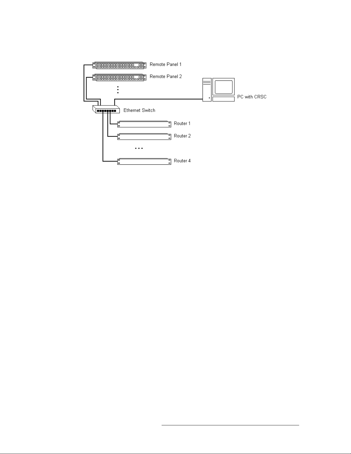
A CRSC network can be comprised of:
• From 1 to 16 remote panel modules (with attached control panels).
You can add at most 16 remote panel modules at any one time. Once added—with network
addresses assigned in CRSC—the frames remain identifiable and configurable and more frames
can be added.
• From 1 to 4 compact routers. You can mix CR Series routers of any size and type according to
your requirements.
You can add at most 4 routers at any one time. If the routers you are adding are already set to
use different subnets, the limit of 4 does not hold. However, routers from the factory are usually
set to the same subnet: 192.168.2. Routers that are freshly initialized also use that subnet.
The network must also include:
• One or more PCs (running Windows XP or Vista) on which you have installed CRSC or other
configuration software.
• An Ethernet switch (or hub) capable of 100 MB/s operation with enough ports to accommodate
your routers, remote panels, and PCs.
If you are using only CR Series routers, the typical network uses a single Ethernet switch, a single
subnet, and a variety of routers, panels, and configuration PCs connected at the switch. If you are
also using any CQX routers and control panels, a second, separate subnet must be created for the
CQX products. The control panels and routers communicate by sending messages across the network. The different devices on the network are identifiable by their unique numbers (IP addresses).
If any routers or control panels on the network have identical IP addresses, the devices are not distinguishable and the network may not functions properly. CRSC notifies you of any identical IP
addresses and which frames are inaccessible on a specific subnet.
8 Rev 2.0 • 29 Mar 10
Page 21
2. Before Using CRSC
Creating a Network
Figure 2-1 shows a sample network of routers with remote panel modules.
Figure 2-1. Sample Network
You can create multiple CRSC networks. CRSC can detect and manage all networks as long as two
conditions are met:
• Each network is defined as a distinct subnet.
• Your configuration PC has enough network connections to support the different subnets.
What is a Subnet?
A subnet is an identifiably separate part of an organization's network that allows a single large network to be broken down into smaller ones. Typically, a subnet may represent all the machines at
one geographic location or on the same local area network (LAN). All CR Series routers and control panels must be on a separate subnet from any CQX routers and control panels. However,
devices must be on the same subnet to communicate with each other. For example, a router can
only receive commands from a control panel on the same subnet.
What is a Subnet Mask?
A subnet mask is the technique used by the IP protocol to create a subnet address. Or, to put it
another way, a subnet mask is a screen of numbers used for routing traffic within a subnetwork. In
CRSC, the subnet mask is typically: 255.255.255.0. The subnet masks need not be 255.255.255.0,
but if it differs, the frame address range will be something other than 1–254.
What is an IP Address?
An IP address is a 32-bit number given by four 8-bit values (octets) separated by periods:
192.168.2.87 (for example). The number is comprised of a subnet and a frame address. Each network must be a distinct subnet in CRSC and CR Series routers and CR Series panels must be on a
separate subnet from CQX routers and CQX control panels.
Using that subnet, a router’s or remote panel’s frame address is the last octet in the address. For
example, if the router’s full IP address is 192.168.2.87, the router’s frame address is 87 and the subnet is 192.168.2. A frame address can range from 1 to 254. The values 0 and 255 are not allowed
because they have special meaning.
Compact Router System Configurator • User’s Guide 9
Page 22

2. Before Using CRSC
Creating a Network
Rotary Switches
The 16-position rotary switch located on the front of a router or remote panel module is used to
determine a device’s initial IP address. Routers and remote panel modules usually come from the
factory with the switch set to 1. Once the frames are added to your network, you can use CRSC to
assign a different IP addresses, if you want. After that, the rotary switches are generally irrelevant.
The switches have hexadecimal position numbers from 0 to 9 and A to F. In hex notation, each letter represents the following:
A = 10, B = 11, C = 12, D = 13, E = 14, F = 15
The switch is then added to a present number to create the initial IP address for the router or panel.
If a rotary switch is set to zero (0), the router or panel reverts to the factory default state, not to a
previously set state.
In the following, the subnet is represented by xxx.yyy.zzz:
For CR Series routers, IP address = xxx.yyy.zzz.sss where sss = switch value + 100.
For CQX routers, IP address = xxx.yyy.zzz.sss where sss = switch value + 200. Use only a
switch setting in the range 1–4 (addresses 201 to 204).
For remote panel modules, IP address = xxx.yyy.zzz.sss where sss = switch value + 50.
Using these formulas, a router and a control panel can have the same switch setting because each is
being added to a unique number. However, two routers or two control panels cannot have the same
switch setting because the resulting number would be the same creating identical IP addresses.
Remember that each device must have a unique IP address. If the devices are on the same subnet,
use the rotary switch setting plus the value listed above to create the default, IP address making
sure that the frame number is unique.
Remember that CQX routers and control panels must be on a separate subnet.
For instructions on setting switch settings, see How to Add Routers to a Network
How to Add Remote Panels to a Network
the network, you can change its IP address using CRSC. See How to Change Ethernet Settings
page 22.
on page 21. After you add the router or remote panel to
on page 20 and
on
Initial Assembly
During the initial physical assembly of routers, panels, and remote panel modules, you need to
ensure that:
• All routers and remote panel modules have their rotary switches set to unique settings before
adding them to the network
• The switch settings of the routers and remote panel modules are non-zero and distinct.
Powering Up Re-initializes
A router or remote panel module re-initializes to its factory default settings if you power it up with
the rotary switch set to zero (0). If you reset the frame by accident, and the frame is in your network, you will have to add the frame again and reconfigure it.
10 Rev 2.0 • 29 Mar 10
Page 23
2. Before Using CRSC
Creating a Network
Network Speeds
Compact router networks are Ethernet LANs (100 Mb/s, UDP). That means they are reasonably
fast, and have potentially many network configuration options. However, no matter how fast the
network is, the amount of network traffic increases exponentially with the number of devices on the
network. At some point, the traffic exceeds the capacity of the network. The practical limit is 4
compact routers and about 16 remote panel modules.
Cabling
In general, router networks and machine control ports use ordinary Ethernet cable and connectors
(RJ-45). However, some frames have DE9 connectors. To make network connections to these
devices, you will need to acquire DE9-to-RJ45 cables.
Analog audio connectors are DB25. Each connector supports 8 audio channels (4 stereo pairs). You
will need to acquire breakout cables to connect individual analog audio devices, such as Miranda’s
WC0053 breakout cable.
CQX Networks
A CQX router must be operated with a CQX control panel (or automation). Do not place a CQX
router on a subnet with other routers. However, you can have more than one subnet dedicated to
CQX routers.
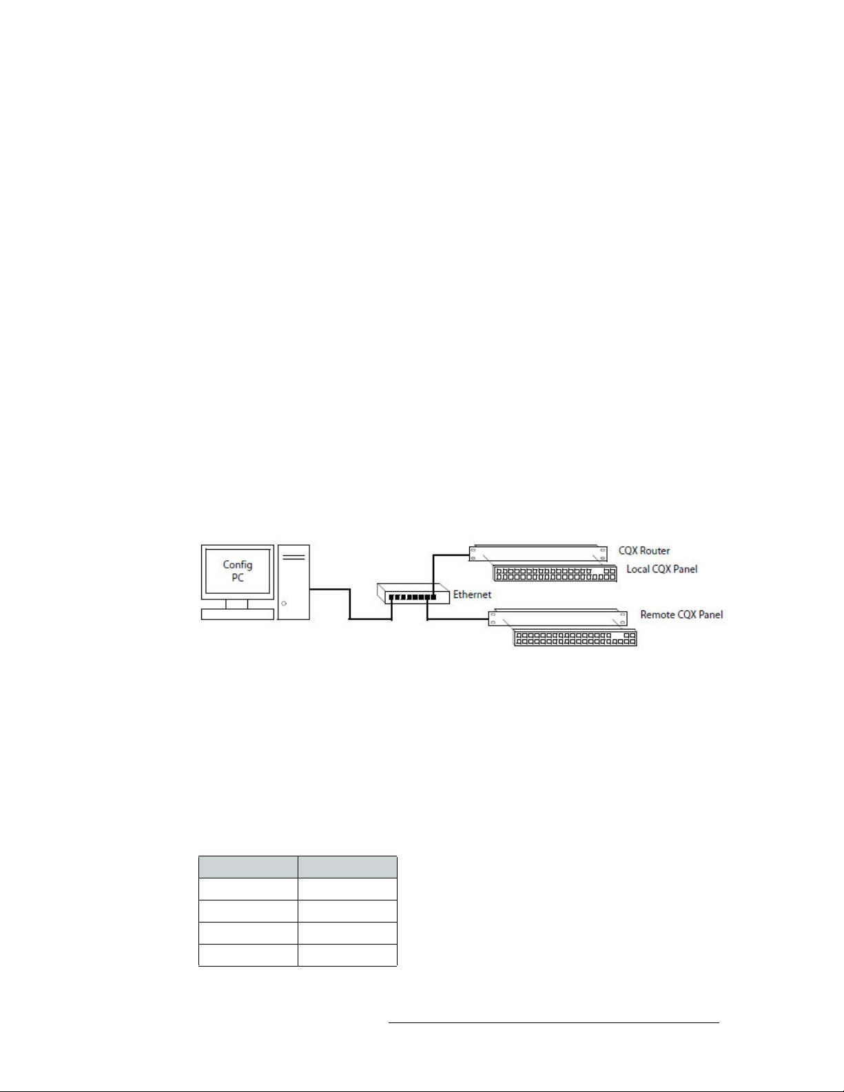
Figure 3-3 shows the ways a “clean and quiet” router can be connected:
Figure 2-2. Figure 3-3. CQX Network
The CQX panel can be local (mounted on a CQX router) or it can be remote (mounted on a remote
panel module). The remote CQX panel then must be connected to the CQX router by an Ethernet
switch. It is possible to use both a captive panel and a remote panel.
Unlike other compact routers, the CQX routers have two rotary switches. You must set both
switches to an appropriate value.
Mode Rotary Switch
The ‘Mode’ rotary switch configures the router’s video format. Set this 16-position rotary switch to
a position in the range 0–5 according to this table:
Setting Format
0 1080i, 59.94
1 1080i, 50
2 525i, 59.94
3 625i, 50
Compact Router System Configurator • User’s Guide 11
Page 24
2. Before Using CRSC
Setting Up the Configuration PC and Installing CRSC
Setting Format
4 720p, 59.94
5 720p, 50
The 1080p formats are not yet available. The default is 1080i, 59.94 Hz (switch setting 0).
Note Every time you make a switch change, power-cycle the router.
Frame ID Rotary Switch
You must set up the IP addresses for the router (and a remote panel, if you have one). First, use the
rotary switch on the router (and remote panel module) to set an initial IP address. For a CQX router,
the address = switch value + 200. The default IP address is 192.168.2.address. Thus, address ranges
from 201 to 215. However, use only a switch setting in the range 1–4 (addresses 201 to 204).
For remote panel modules, address = switch value + 50. The default IP address is
192.168.2.address. Here, address ranges from 51 to 65.
The numbers on the rotary switch are in hexadecimal: 0–F. Do not use 0 because 0 causes the router
or remote panel module to be reset. After you perform the setup using the rotary switches, you can
use CRSC to change the IP addresses from the defaults.
Note Every time you make a switch change, power-cycle the router.
Setting Up the Configuration PC and Installing CRSC
After the CRSC network is setup, you are ready to configure the PC that will run CRSC. Once the
PC is configured, you can install the CRSC application on that computer.
The PC must be assigned an IP address on one of the subnets you intend to use for the CRSC network. Usually the subnet is 192.168.2 because that is the default subnet assigned to all Compact
Router Series products.
If you have multiple subnets in your compact router system, you will probably have to add those
subnets to your PC’s network configuration. Doing this is especially important for CQX routers.
12 Rev 2.0 • 29 Mar 10
Page 25
2. Before Using CRSC
Setting Up the Configuration PC and Installing CRSC
How to Configure your PC’s IP Address
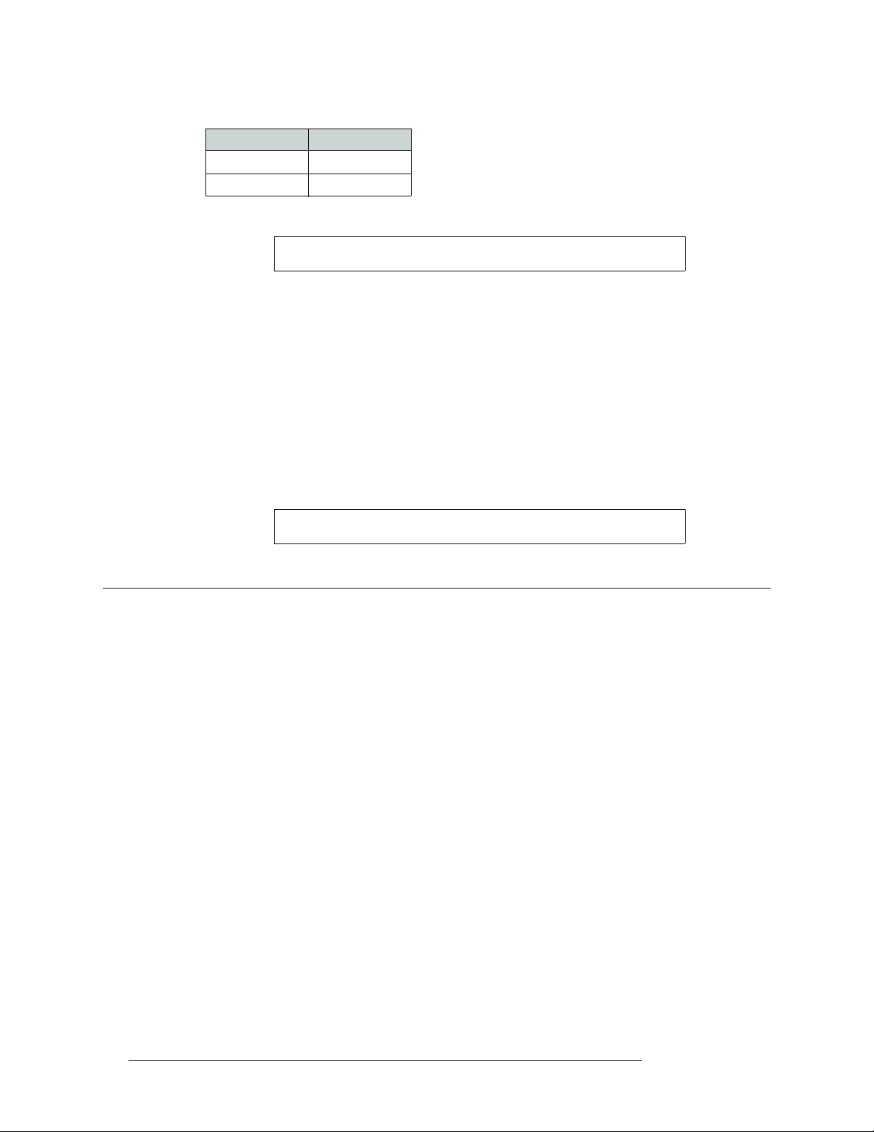
1 From the PC’s Start menu, choose ‘Settings > Network Connections’ or 'All Programs > Acces-
sories > Communications > Network Connections', whichever is available. The ‘Network Connections’ dialog box appears:
Figure 2-3. Network Connections Window
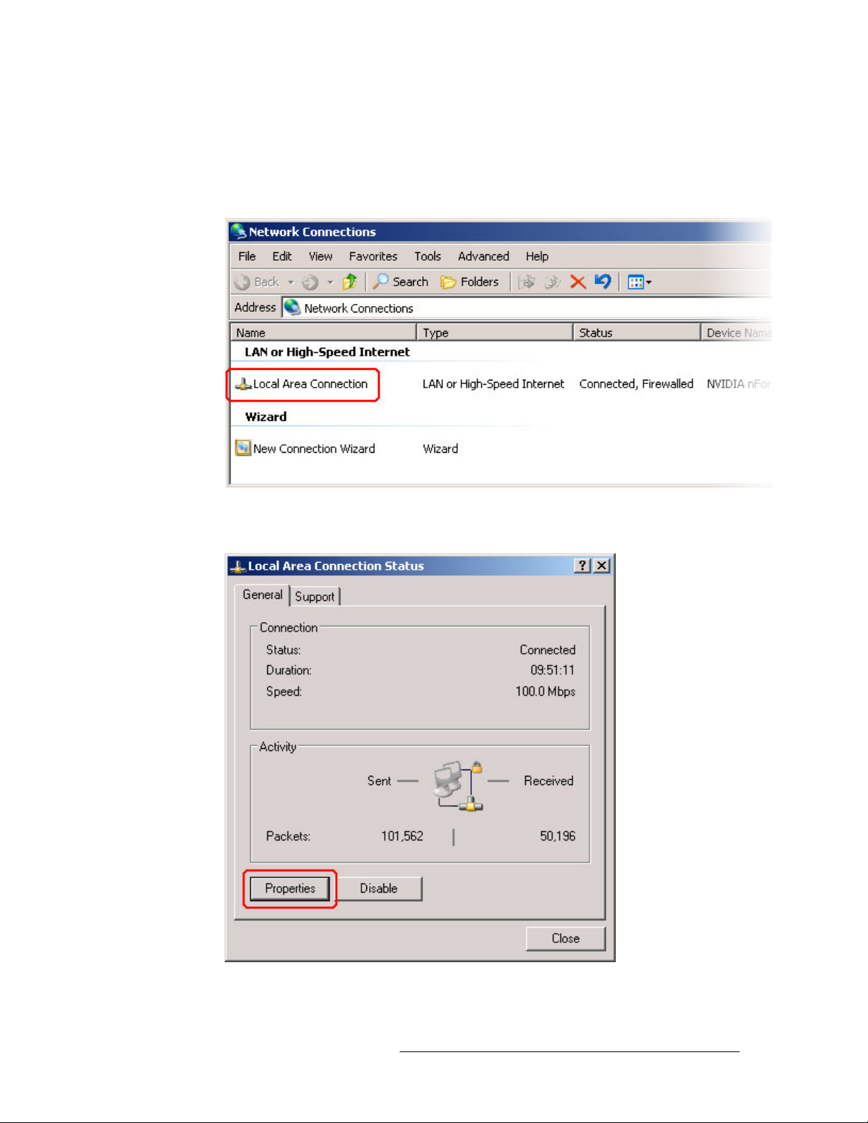
2 Double-click ‘Local Area Connection’. The ‘Local Area Connection Status’ dialog box
appears:
Figure 2-4. Local Area Connection Status Dialog Box
Compact Router System Configurator • User’s Guide 13
Page 26
2. Before Using CRSC
Setting Up the Configuration PC and Installing CRSC
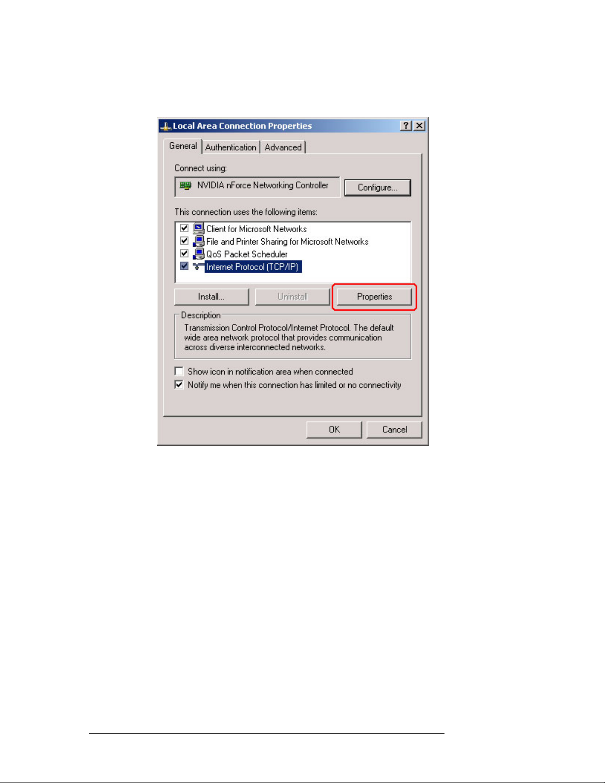
3 Choose the ‘General’ tab and click Properties. The ‘Local Area Connection Properties’ dialog
box appears.
Figure 2-5. Local Area Connection Properties Dialog Box
14 Rev 2.0 • 29 Mar 10
Page 27
2. Before Using CRSC
Setting Up the Configuration PC and Installing CRSC
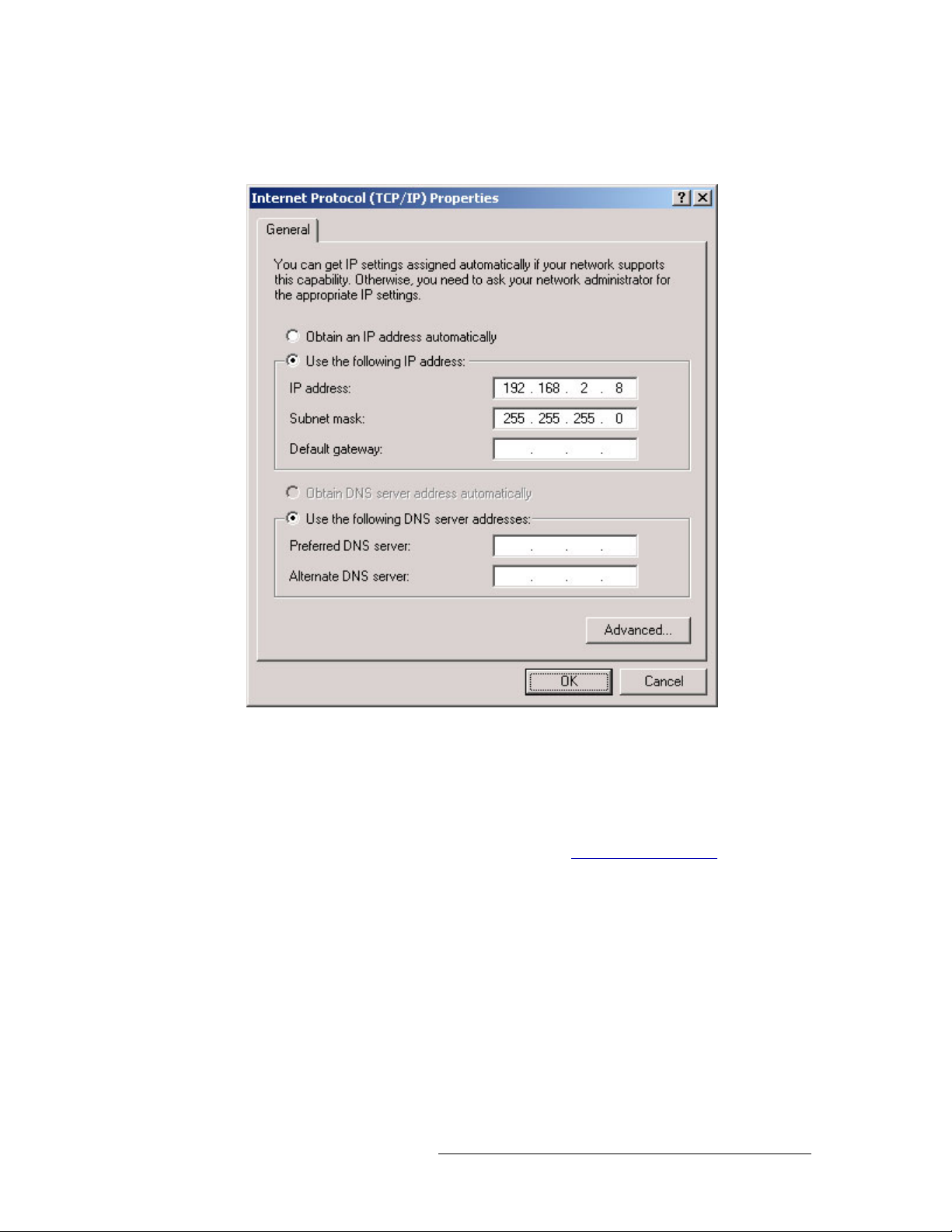
4 Select ‘Internet Protocol (TCP/IP)’ and click Properties. The ‘Internet Protocol (TCP/IP) Prop-
erties’ dialog box appears.
Figure 2-6. Internet Protocol (TCP/IP) Properties Dialog Box
5 Select ‘Use the following IP address’ and enter the IP address for your PC. It is recommended
that you use the default subnet 192.168.2 and the subnet mask 255.255.255.0.
Any unique IP address will work as long as it is on one of the subnets of your CRSC network.
The PC’s address on the subnet must not be the same as any of the frames (routers or remote
panels) on the subnet. It is recommended that you use Avoid addresses in the 50, 100 and 200
range. CRSC uses those as defaults. For details, see What is an IP Address?
6Click
OK to save your changes.
on page 9.
How to Create Multiple Subnets
1 Starting from step 4 in the preceding procedure, click Advanced.
2 In the ‘Advanced’ window, click
nets. Repeat this step for additional subnets.
3 After adding IP addresses for your subnets, click
Compact Router System Configurator • User’s Guide 15
Add and enter an IP address for your PC on each of the sub-
OK.
Page 28

2. Before Using CRSC
Installation Testing
How to Install CRSC
The CR Series (Compact Router) is available on the CD (SB0033-xx) that ships with the equipment. CRSC is a Java application and the installer installs a Java runtime support package. The
installer creates a desktop shortcut for CRSC and makes an entry in Windows’ Start menu for
CRSC.
To install, place the CD in the CD drive of your PC. The CD should autoplay and present an option
to run the CRSC installer. Choose the option and follow the instructions. The software installation
process takes about one minute.
Installation Testing
After installing CRSC, launch CRSC by clicking the desktop icon or selecting ‘NVISION > Compact Router System Configurator’ from the ‘Start’ menu. Click the ‘Compact Router Series Ethernet Settings’ link to open the ‘Compact Router Series Ethernet Settings’ page and view list of
devices in your network.
Examine the list of devices and note if any of the following exist:
• No entries in the list. Either you have no network or the network is not properly connected to
your PC. Ensure that your PC has an Ethernet connection to the Ethernet switch for the network.
• Entries read “IP Conflict.” There might be a duplicate IP address. To fix this issue, adjust the
rotary switch setting on your frames. The switch settings for each router must be unique from
any other router; the switch settings for each remote panel module must be unique from any
other remote panel module. (See Rotary Switches
If you determine that IP addresses are not a problem, one of the frames might be disconnected,
have no power, or might be defective. Again, check Ethernet connections, power connections,
and power supplies. A power supply light and the power indicators on all routers, remote panel
modules, and control panels should be on.
• Entries read “Different Subnet.” These are frames that are detectable by CRSC, but are not on a
currently available subnet. To view available subnets, move the mouse pointer and hover over
“Different Subnet.” A popup list of available subnets appears.
There are several options for such entries:
Change the IP address of the frame to the current subnet.
Change the IP address or subnet of the configuration PC.
Change the IP address in some other way, but leaving the device on some other subnet.
Physically remove the frame from the network by disconnecting the connecting cables.
Fix any problems and click
view an updated list of devices. Once the network is functioning properly, you are ready to use
CRSC to perform other tasks.
on page 10.)
Refresh List on the ‘Compact Router Series Ethernet Settings’ page to
16 Rev 2.0 • 29 Mar 10
Page 29
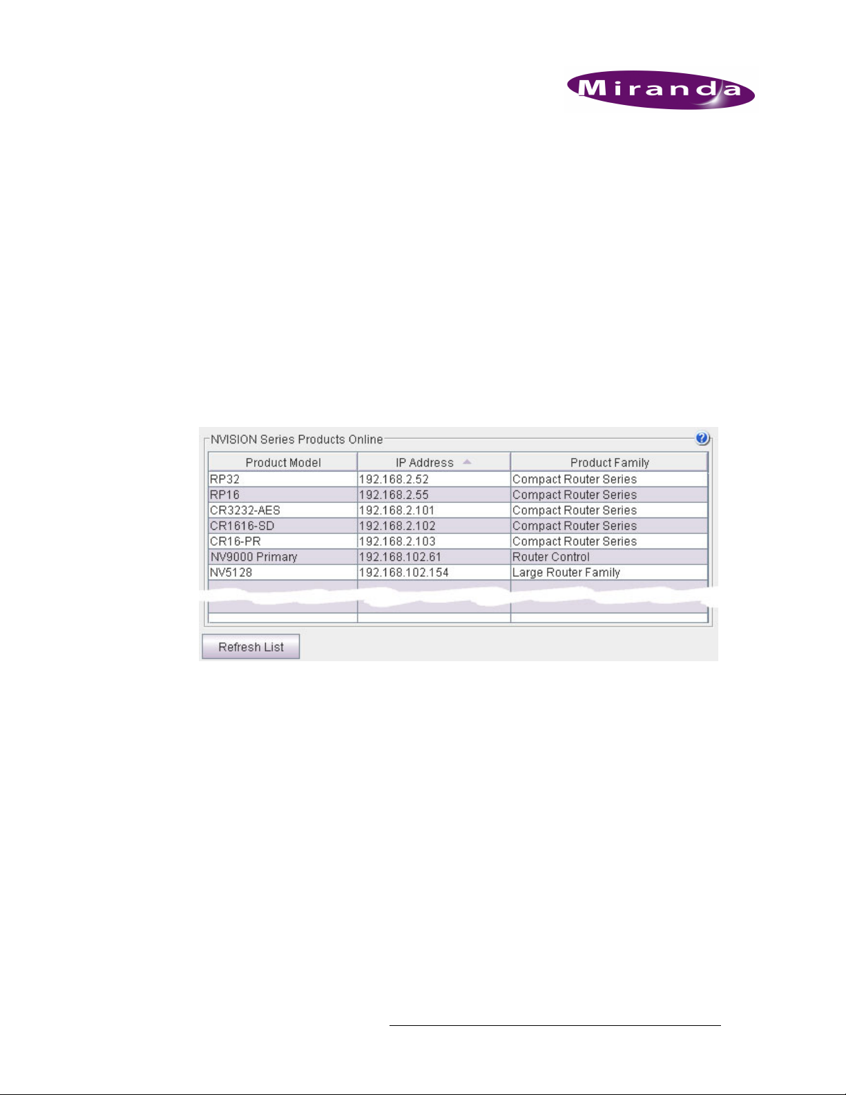
3. Show Products Online
The ‘NVISION Series Products Online’ page lists all products — compact routers, remote panels,
large routers, router control systems
nected.
The page lists the product name and model, the IP address, and the device family for all detectable
products. Use this page for reference when determining what products can be configured. The page
is for information only.
To open the ‘Show NVISION Products Online’ page, from the navigation pane click ‘Show NVISION Products Online’ under the ‘Home’ bar. The ‘Show NVISION Products Online’ page
appears in the right-hand pane. At any time, click
ucts.
— detectable on the networks to which the CRSC PC is con-
Refresh List to view the most recent list of prod-
Figure 3-1. Show NVISION Products Online Page
Compact Router System Configurator • User’s Guide 17
Page 30

3. Show Products Online
18 Rev 2.0 • 29 Mar 10
Page 31

4. CR Series Ethernet Setttings
Using the ‘CR Series Ethernet Settings’ page you can change the name, IP address, subnet mask, or
gateway IP address of any compact router or remote panel module. In order for routers and panels
to be able to communicate they must be part of a network. (Click ‘Show NVISION Products
Online’ to see a list of routers and panels on the network.) Each device has a unique IP address
assigned to it. For information on setting up the initial network, see Creating a Network
Routers and panels are also assigned a subnet mask. A subnet mask is an identifiably separate part
of an organization's network. Typically, a subnet mask may represent all the machines at one geographic location or on the same local area network (LAN). This manual assumes a basic knowledge
of networks. If you are unsure about any IP address, subnet mask or gateway information required,
contact your System Administrator.
CQX Routers — Separate Subnet
The CQX router must be operated with a CQX control panel, either mounted on a CQX router
(local) or on a remote panel module (remote). When setting up the network it is important to assign
all CQX routers and CQX panels a subnet separate from other Compact Router Series (CR Series)
routers or control panels. CQX products and CR Series products cannot be on the same subnet. See
CQX Networks
detailed instructions, see the CR Series Compact Router User’s Guide.
on page 11.You can also setup more than one subnet on a single switch. For
on page 8.
To open the ‘CR Series Ethernet Settings’ page, from the navigation pane, click ‘CR Series Ethernet Settings’ under the ‘CR Series Network Setup’ bar. The ‘CR Series Ethernet Settings’ page
appears in the right-hand pane.At any time, click
An Overview of Networking
The Compact Router System Configurator (CRSC) resides on a PC connected to a network. This
network includes the router and remote panel modules that CRSC manages. If you are unfamiliar
with networks, please review Creating a Network
Refresh List to view the latest network details.
on page 8.
Compact Router System Configurator • User’s Guide 19
Page 32

4. CR Series Ethernet Setttings
An Overview of Networking
Using the ‘CR Series Ethernet Settings’ Page
The ‘Ethernet settings’ page lists compact routers and remote panel modules available on the
CRSC network.
Figure 4-1. CR Series Ethernet Settings Page
Each column presents the following option or information:
Column Description
Update Check the check box to select the frame listed on that row for updating.
Name Name of the compact router or remote panel.
Frame Type Type (model #) of compact router or remote panel, such as CP3232.
IP Address IP address currently assigned to the device.
Subnet Mask Subnet mask currently assigned to the device. It is recommended that you leave the
subnet mask at 255.255.255.0.
Gateway IP Gateways are not used except by third-party systems or occasionally by an NV9000
Mode The ‘Mode’ column is status-only and displays how the particular router or remote panel
Identify CP When you click
system. Developers may use the gateway and subnet mask fields in any way they deem
useful. A gateway setting is not needed for a normal compact router setup.
module is configured. These are the 3 possible “modes”:
NA
— The frame is either a remote panel module or a router with old software.
Config
Default
mode.
displaying a moving pattern of button lights. This feature is helpful if you forget which
panel of possibly many is represented by the particular IP address. The moving button
lights continue indefinitely. To turn off the pattern, click any button on the panel or click
Identify CP again.
— The frame is a router configured with CRSC.
— No settings have been changed and the frame is a router in the factory default
Identify CP, the remote panel listed on that row identifies itself by
How to Add Routers to a Network
You can only add up to 4 routers at any one time because there can only be 4 routers in a subnet. If
the routers being added are already set to use different subnets, the limit of 4 does not apply. However, routers from the factory are usually set to the same subnet: 192.168.2. Routers that are freshly
initialized also use that subnet.
Adding a router to the CR system creates a new level. Routers are assigned to a subnet and no more
than 8 levels in any single subnet is allowed. CRSC will not let you delete a router you just added
20 Rev 2.0 • 29 Mar 10
Page 33

4. CR Series Ethernet Setttings
An Overview of Networking
because each router must correspond to at least one level. Either disconnect the router physically,
delete one or more levels (other than those just added), or move the router to another subnet. Levels
are managed using the ‘Setup Router Levels’ page. See Configuring Router Levels
Only CQX control panels can be used with CQX routers. Both the CQX router and CQX panel
must be on the same subnet, but a different subnet than other CR Series routers and panels. See
Creating a Network
Note If your subnet mask is 255.255.255.0, CRSC does not allow a frame address out-
1 Connect one or more remote panel modules (16 or fewer) to your network with unique rotary
switch settings from 0 to 15. See Rotary Switches
position numbers from 0 to 9 and A to F. In hex notation, the letters mean the following:
A = 10, B = 11, C = 12, D = 13, E = 14, F = 15.
Note If a rotary switch is set to zero (0), the router reverts to the factory default
on page 8.
side the range 1–254. You can use other subnet masks and other address ranges.
on page 10. The switches have hexadecimal
state, not to a previously set state.
on page 25.
2 From the side navigation pane, click ‘CR Series Ethernet Settings’ page under the ‘CR Series
Network Setup’ bar.
3 On the ‘CR Series Ethernet Setting page’, verify that all routers appear in the list.
4 For each router, click on the cell in the ‘IP Address’ column to activate the field. (A check mark
appears in the ‘Update’ check box). Enter a unique IP address according to the following formulas:
CR Series routers – xxx.yyy.zzz.s where s = the switch setting plus 100.
CQX routers – xxx.yyy.zzz.s where s = the switch setting plus 200. Use only a switch setting in
the range 1–4 (addresses 201 to 204).
Each IP address must be unique. The default subnet (xxx.yyy.zzz) for CR Series routers and
panels is 192.168.2. CQX routers and CQX panels must exist on a separate subnet.
5 Repeat steps 1 through 4 for each router. Remember that no more than 4 routers can be added to
a single subnet.
6 Important! Click
with ‘Update’ checked are updated. The changes are stored in the frames’ internal configuration
data.
7 Remember to cycle power after you change a rotary switch.
Apply Updates to send the changes to the selected frames. Only those frames
How to Add Remote Panels to a Network
You can only add up to 16 remote panel modules at any one time because there are only 16 switch
positions. If your subnet mask is 255.255.255.0, CRSC does not allow a frame address outside the
range 1–254. You can use other subnet masks and other address ranges.
Only CQX control panels can be used with CQX routers. Both the CQX router and CQX panel
must be on the same subnet, but a different subnet than other CR Series routers and panels. See
Creating a Network
Compact Router System Configurator • User’s Guide 21
on page 8.
Page 34

4. CR Series Ethernet Setttings
An Overview of Networking
1 Connect the remote panel modules (16 or fewer) to the network with unique rotary switch set-
tings from 0 to 15. The switches have hexadecimal position numbers from 0 to 9 and A to F. In
hex notation, the letter mean the following:
A = 10, B = 11, C = 12, D = 13, E = 14, F = 15.
Note If a rotary switch is set to zero (0), the panel reverts to the factory default
state, not to a previously set state.
2 From the side navigation pane, click ‘CR Series Ethernet Settings’ page under the ‘CR Series
Network Setup’ bar.
3 On the ‘CR Series Ethernet Setting page’, verify that all added remote panels appear in the list.
4 For each remote panel, click on the cell in the ‘IP Address’ column to activate the field. (A
check mark appears in the ‘Update’ check box). Enter a unique IP address according to the following formulas:
Remote panel modules
Each IP address must be unique. The default subnet (xxx.yyy.zzz) for CR Series routers and
panels is 192.168.2. CQX routers and CQX panels must exist on a separate subnet.
5 Repeat steps 1 through 4 for each remote panel. Remember that no more than 16 remote panels
can be added to a single subnet.
6 Important! Click
with ‘Update’ checked are updated. The changes are stored in the frames’ internal configuration
data.
7 Remember to cycle power after you change a rotary switch.
Apply Updates to send the changes to the selected frames. Only those frames
— xxx.yyy.zzz.s where s = the switch setting plus 50.
How to Change Ethernet Settings
Only CQX control panels can be used with CQX routers. Both the CQX router and CQX panel
must be on the same subnet, but a different subnet than other CR Series routers and panels. See
Creating a Network
1 From the navigation pane, click ‘CR Series Ethernet Settings’ under the ‘CR Series Network
Setup’ bar to open the ‘CR Series Ethernet Settings’ page.
2 Locate the row listing the frame you want to update.
3 In the same row, click in cell listed in the column displaying the ‘IP Address’, ‘Subnet Mask’ or
‘Gateway IP’ information you want to update. The field activates.
4 Type in the new value. It is recommended that you leave the subnet masks at 255.255.255.0
unless you are a developer. If updating IP addresses, click the cell in the ‘IP Address’ column
and use the following formulas:
CR Series routers
CQX routers
the range 1–4 (addresses 201 to 204).
Remote panel modules
Each IP address must be unique. The default subnet (xxx.yyy.zzz) for CR Series routers and
panels is 192.168.2. CQX routers and CQX panels must exist on a separate subnet.
on page 8.
— xxx.yyy.zzz.s where s = the switch setting plus 100.
— xxx.yyy.zzz.s where s = the switch setting plus 200. Use only a switch setting in
— xxx.yyy.zzz.s where s = the switch setting plus 50.
22 Rev 2.0 • 29 Mar 10
Page 35

4. CR Series Ethernet Setttings
An Overview of Networking
5 To save your current changes, press Enter or Ta b on your keyboard, or click in another field.
Or
Press
Esc to cancel changes.
6 Repeat steps 2 through 5 until all changes have been made. The ‘Update’ check box automati-
cally displays a check mark if you update any of the information.
7 Important! Click
with ‘Update’ checked are updated. The changes are stored in the frames’ internal configuration
data.
Apply Updates to send the changes to the selected frames. Only those frames
Compact Router System Configurator • User’s Guide 23
Page 36

4. CR Series Ethernet Setttings
An Overview of Networking
24 Rev 2.0 • 29 Mar 10
Page 37

5. Configuring Router Levels
The ‘Configure Router Levels’ page enables you to define up to 4 levels in a router. In CRSC, a
level is created (1) when you create a router partition or (2) when you add a router to the network.
Levels within a router may overlap or they may be distinct. A level may also be the entire router or
just specific inputs and outputs.
Important CQX routers are not designed to use levels. For proper functioning, do not
configure levels in a CQX router.
Adding a router to the Compact Router Series system creates a new level. Routers are assigned to a
subnet and no more than 8 levels in any single subnet is allowed. See An Overview of Networking
on page 19. CRSC will not let you delete a router you just added because each router must correspond to at least one level. Either disconnect the router physically, delete one or more levels (other
than those just added), or move the router to another subnet. Miranda does not guarantee system
performance beyond 4 routers.
To open the ‘Configure Router Levels’ page, from the navigation pane, click ‘Configure Router
Levels’ under the ‘CR Series Network Setup’ bar. The ‘Configure Router Levels’ page appears in
the right-hand pane.
At any time, click Refresh Summary at the bottom of the page to repopulate the ‘Configure Router
Levels’ page. This is important to do periodically so that accurate data displays, particularly when
you make new physical connections.
Overview
Levels and Partitions
Partitions are boundaries within the router used to organize switching. This defines what signal format is in use and enables the control card to determine the correct switching rules and reference
requirements.
Signals are switched within a partition, not between partitions. Inputs can be switched only to outputs contained in the same partition. Every switching matrix must contain at least one partition. It is
not required that different signal formats be split into separate partitions, and in fact, one partition
for an entire router may be desirable.
CRSC uses virtual partitions instead of physical partitions, called “levels”. In CRSC, levels are
analogous to partitions. A level is automatically created (1) when you create a router partition or (2)
Compact Router System Configurator • User’s Guide 25
Page 38

5. Configuring Router Levels
Overview
when you add a router to the network. CRSC allows you to define up to 8 levels in total and up to 4
levels per router.
Important CQX Routers are not designed to use levels. For proper functioning, do not
configure levels in a CQX router.
Using the ‘Configure Router Levels’ Page
At the top of the page, the ‘Setup Crosspoint Ranges for Levels’ displays all levels currently added
and enables you to add and update levels as needed. In the lower section of the page the ‘Network
Frame Summary’ has two tabs that display data related to routers for easy reference. Each tab displays either ‘Routers’ or ‘All CR Frames’ (compact routers) defined in your network.
Figure 5-1. Configure Router Levels Page
26 Rev 2.0 • 29 Mar 10
Page 39

5. Configuring Router Levels
Overview
The ‘Setup Crosspoint Ranges for Levels’ section display the following information:
Column Description
Level Number Number assigned to the level. The number must be unique and between 1
and 250.
Level Name Name assigned to the level. Usually this is a signal type and limited to 16
characters.
Router Name Router that contains the level.
Signal Type Type of signal switched on that level. See Signal Types
Physical Input Start Use these fields to define the physical start and endpoints of the level within
Physical Input End
Physical Output Start
Physical Output End
Controller Source Start I/O numbering in the system controller may not match the physical I/Os in
Controller Destination Start
the router.
the router. Use these fields to map the router I/Os to the system controller I/
O numbering.
The ‘Network Frame Summary’ presents the following information:
on page 28.
Tab Column Description
Routers Name Name of the compact router or remote panel.
Frame Type Type of router or remote panel.
Level(s) Level numbers associated with the router. Each level is assigned a
IP Address IP address currently assigned to the device.
Subnet Mask Subnet mask currently assigned to the device. It is recommended that
All CR Frames Frame Type Type of compact router.
Level(s) Level numbers associated with the router.
Subnet Mask Subnet mask currently assigned to the device. It is recommended that
unique number.
you leave the subnet masks at 255.255.255.0 unless you are a
developer.
you leave the subnet masks at 255.255.255.0 unless you are a
developer.
Active Subnet
CRSC detects all subnets for which there are connections in your configuration PC. You can place
different frames on different subnets and use any available subnet you want. Choose the subnet
from the ‘Active Subnet’ drop-down list. The router levels page refreshes its lists of frames after
you choose a different subnet.
The designation “active” applies only in Compact Router itself: it is the subnet you are configuring.
In the actual network, all subnets operate independently and concurrently. An Ethernet switch is
usually required for each subnet.
Compact Router System Configurator • User’s Guide 27
Page 40

5. Configuring Router Levels
Overview
Signal Types
The Compact Router Series routers can switch one or more signal types.
AV
AA
AES
SD
HD
3Gig
PR
AES signals and machine control signals are unique from video signals. If you are unfamiliar with
the various signal types, please review Signals
Analog Video or Timecode
Analog Audio or Timecode
Synchronous AES Mono
SD Digital Video
HD or SD Digital Video
3Gig, HD, or SD Digital Video
Machine Control Reverse
on page 65.
How to Create or Update a Level
All level information can be updated except for router names and signal types. These are automatically generated. For every level you define, the ‘Signal Type’ column displays the signal for that
level. See Overview
Important CQX Routers are not designed to use levels. For proper functioning, do not
1 From the left-hand navigation area, expand the ‘CR Series Network Setup’ pane and click
‘Configure Router Levels’.
2 On the ‘Configure Router Levels’ page, in the ‘Setup Crosspoint Ranges for Levels’ section
locate the row listing the level being updated and make changes as described in the following
steps.
Or
To add a new level:
aClick
on page 25., Signal Types.
configure levels in a CQX router.
Add Level. The ‘Select a Router’ dialog box appears.
Figure 5-2. Select a Router Dialog Box
b Click the arrow to the right of the field and from the drop-down list select a router and then
click
OK. A row is added to the ‘Setup Crosspoint Ranges for Levels’ section unless you
have already defined 8 levels.
3 On the same row, click in the ‘Level Number’ or ‘Level Name’ cell to activate the field and
enter new values, if desired. Level numbers are limited to 1 to 250 and must be unique. Level
names are limited to 16 characters.
4 Define the physical start and endpoints for the level. These are the actual I/O connections on the
router:
a In the row, in the ‘Physical Input Start’ column, enter the starting input number.
b In the same row, in the ‘Physical Input End’ column, enter the ending input number.
28 Rev 2.0 • 29 Mar 10
Page 41

5. Configuring Router Levels
Overview
c In the row, in the ‘Physical Output Start’ column, enter the starting output number.
d In the same row, in the ‘Physical Output End’ column, enter the ending output number.
5 In the ‘Controller Input Start’ and ‘Controller Destination Start’ columns, assign a starting point
to the partitions. In the example in Figure 5-3, inputs and outputs are numbered from 1 to 32 in
both partitions, even though the partitions use different parts of the router.
The numbers entered in the ‘Controller Source Start’ and ‘Controller Destination Start’ fields
are used for the destination and source buttons in the ‘Program Remote Panels’ page. See Pro-
gramming Remote Panels on page 37.
Figure 5-3. Example of Levels for AES Signals
6 When you have finished defining levels, click Update Router Levels to send the partition data to
the routers.
How to Create Multiple Levels
Important CQX Routers are not designed to use levels. For proper functioning, do not
configure levels in a CQX router.
To create multiple levels for a router, add levels that reference the same router. For example, a
CR3232-AES router might have two partitions:
Level 2, 32 inputs × 32 outputs, numbered from 1 to 32
Level 3, 32 inputs × 32 outputs, numbered from 33 to 64
The resulting configuration would resemble Figure 5-4.
Figure 5-4. Example of Levels for AES Signals
How to Delete a Level
1 From the left-hand navigation area, expand the ‘CR Series Network Setup’ pane and click
‘Configure Router Levels’.
2 On the ‘Configure Router Levels’ page, click on the row listing the level and click
3Click
Update Router Levels to send the updated partition data to the routers.
Delete Level.
Compact Router System Configurator • User’s Guide 29
Page 42

5. Configuring Router Levels
Overview
30 Rev 2.0 • 29 Mar 10
Page 43

6. Setting Up Machine Control Routers
The ‘Setup Machine Control Router’ page enables you to configure port types for machine control
routers. In general, machine control routers are switched separately from other routers because of
the differences in the behavior of the ports. Unlike other routers, machine control routers have bidirectional ports and routes are port-to-port.
To open the ‘Setup Machine Control Router’ page, from the navigation pane, click ‘Setup Machine
Control Router’ under the ‘System Configuration’ bar. The ‘Setup Machine Control Router’ page
appears in the right-hand pane.
At any time, click
Refresh Summary to view the latest list of machine control routers in the system.
An Overview of Machine Control Routers
Compact machine control routers are different from other compact routers because they can receive
signals from both controlled and controlling devices depending on the their port settings. A controlling port is defined as one that is connected to a controlling device. A controlled port is one connected to a controlled device.
Machine control routers have unique features:
• Machine control routers have bidirectional ports. Because machine control routers have bidirectional ports (A to B, B to A), whatever connections you make appear twice in the ‘View Router
Crosspoints’ page twice: once in the lower left portion of the matrix and once in the upper right.
• Machine control routes are point-to-point
a column on the ‘View Router Crosspoint’ page.
For more information about machine control signals, see Signals
— one input, one output. Outputs only appear once in
on page 65.
Compact Router System Configurator • User’s Guide 31
Page 44

6. Setting Up Machine Control Routers
An Overview of Machine Control Routers
Viewing Machine Control Router Crosspoints
The display of machine control matrices is different from that of other matrices.
Figure 6-1. View Router Crosspoints Page
In this matrix, ports 4 and 7 are connected. The square (A) at row 4 and column 7 is highlighted.
The square (B) at row 7 and column 4 is also highlighted.
If the two ports (in this example, ports 4 and 7) are dynamic ports, then clicking box A and clicking
box B give different results. Either way connects ports 4 and 7, but clicking box B makes port 7
controlled whereas clicking box A makes port 7 controlling.
A controlling port is defined as one that is connected to a controlling device. A controlled port is
one connected to a controlled device.
A dynamic port is one that can change. If a port is not dynamic, its configuration does not change.
S Clicking box A has the same effect as pressing destination (DST) 7 then source (SRC) 4 on a
panel.
S Clicking box B has the same effect as pressing DST 4 then SRC 7 on a panel.
In general, clicking column C, row R has the same effect as pressing DST C then SRC R: columns
are destinations and rows are sources.
When a port is on the diagonal, it is tri-stated or disabled. It neither transmits nor receives. Clicking
a column head for a machine control router is a no-op.
Machine Control Router Port Types
A device can be considered a “controlled” device or a “controlling” device. A controlling device
sends commands to a controlled device. The controlled device passes responses (such as status)
back to the controlling device. Both source devices and destination devices can be a controlling
device or a controlled device.
32 Rev 2.0 • 29 Mar 10
Page 45

6. Setting Up Machine Control Routers
An Overview of Machine Control Routers
The illustration below shows that the source device is a controlling device.
A destination can also be the controlling device, as shown below.
Note Some external devices must be placed in “remote” mode to work with a machine
control router.
A controlling port is one connected to a controlling device. A controlled port is one connected to a
controlled device.
The compact machine control routers operate in “data reverse” mode. This means that in any connection, the destination device is the controlling device. That is the default. It can be overridden by
port type.
Machine control routers have five port types, each of which is a variation of “controlled” or “controlling”:
• Controlling or Controlled
The port settings fix the direction of the router port to “controlling” or “controlled.” The port’s
connection for Tx and Rx — made during configuration — is static and does not change during
operation.
•Dynamic
A dynamic port can be a controlling or controlled port depending on whether it is connected to
a master port or slave port. The port’s configuration is dynamic and can change during operation. Dynamic ports are typically assigned to VTRs.
A dynamic port may connect to any port.
• Master or Slave
Any dynamic port connected to a “master” port will be changed to a controlled port. A “slave”
port is the opposite of a “master” port: any dynamic port connected to a slave port will be
changed to a controlling port.
A master port must connect to either a dynamic or controlled port. A slave port must connect to
either a dynamic port or a controlling port.
The compact router applies logic to the port direction setting when a master port is connected to a
dynamic port. In this case, the machine at the dynamic port is always controlled and the machine at
the master port is always controlling.
In general, a controlling port connects to a controlled port. (Dynamic, master, and slave port types
are variants of “controlled” and “controlling.”)
Compact Router System Configurator • User’s Guide 33
Page 46

6. Setting Up Machine Control Routers
An Overview of Machine Control Routers
Using the ‘Setup Machine Control Router’ Page
In the upper portion of the ‘Setup Machine Control Router’ page, the ‘Machine Control Port Settings’ section displays all currently added ports and the port type. Using this section you can
change the port type. In the lower portion of the page the ‘Network Frame Summary’ section has
three tabs that display data related to machine control routers for easy reference. Each tab displays
either ‘Machine Control Routers’, ‘Levels’ or ‘All CR Frames’ (compact routers) defined in the
network by Name, Frame Type, IP Address and Subnet Mask.
Figure 6-2. Setup Machine Control Router Page
The ‘Machine Control Port Settings’ section displays the following:
Column Description
Port Number Port number of a port on the machine control router.
Port Type Port type assigned to the port. There are five port types. (See Machine
34 Rev 2.0 • 29 Mar 10
Control Router Port Types on page 32.) Port types are selected from the
drop-down list.
Page 47

6. Setting Up Machine Control Routers
An Overview of Machine Control Routers
The ‘Network Frame Summary’ presents the following option and information:
Tab Column Description
Machine
Control
Routers
Levels Level The level name. Level names map to the level number.
All CR Frames
(lists all frames
in the system)
Edit Select the radio button on the row listing the router you want to edit.
Details display in the ‘Machine Control Port Settings’ section. Once
selected, router information can be updated.
Name Name of the router.
Frame Type Type (model number) of router.
Level(s) Level numbers associated with the router.
IP Address IP address currently assigned to the device.
Subnet Mask Subnet mask currently assigned to the device. We recommend that
you leave the subnet masks at 255.255.255.0 unless you are a
developer.
Signal Type Type of signal(s) assigned to the level.
Router Router to which the level is assigned.
Physical Inputs These fields show the physical start and endpoints of the level within
Physical
Outputs
Controller
Sources
Controller Dest
Name Name assigned to the router.
Frame Type Type (model number) of router.
IP Address IP address currently assigned to the router.
Subnet Mask Subnet mask currently assigned to the device. It is recommended that
the router.
I/O numbering in the system controller may not match the physical I/
Os in the router. Use these fields to map the router I/Os to the system
controller I/O numbering.
you leave the subnet masks at 255.255.255.0 unless you are a
developer.
How to Select a Machine Control Router
To select a specific router, locate the router in the ‘Network Frame Summary’ section and click on
that row. Routers are listed by three different categories. Click the related tab to bring that tab forward:
• Machine Control Routers
Address’
• Levels
— Lists all routers by ‘Level’, ‘Signal Type’, ‘Routers’, ‘Inputs and Outputs’, and ‘Con-
troller Destinations’.
• All CR Frames
— Lists compact router frames by ‘Name’, ‘Frame Type’ and ‘IP Address’.
Details of the port settings for that router display in the ‘Machine Control Port Settings’ section.
Compact Router System Configurator • User’s Guide 35
— Lists machine control routers by ‘Name’, ‘Frame Type’ and ‘IP
Page 48

6. Setting Up Machine Control Routers
An Overview of Machine Control Routers
How to Change a Port Type
1 From the left-hand navigation area, expand the ‘System Configuration’ pane and click ‘Setup
Machine Control Router’.
2 Select the router and locate the row listing the ‘Port Number’ you want to update.
3 On the row, click in the ‘Port Type’ column. A drop-down menu appears:
Figure 6-3. Setup Machine Control Router Page
4 From the drop-down menu, select a new port type. There are five types of ports: ‘Controlled’,
‘Controlling’, ‘Dynamic’, ‘Master’ and ‘Slave’. For a complete description, see An Overview
of Machine Control Routers on page 31.
5Click
36 Rev 2.0 • 29 Mar 10
Update Router. CRSC uploads the port configurations to the router.
Page 49

7. Programming Remote Panels
Using the ‘Program Remote Panels’ page you can choose a panel type and define the button functions for that panel. You can save the panel configuration to a file or upload a saved control panel
configuration to one or more remote panels. Each remote panel in the network requires configuration. A remote panel is the combination of a control panel that is mounted on a remote panel module.
A remote panel module can send control messages to a network of routers and receive station information from the network. Remote panel modules must be attached to a control panel to be used.
The combination of a remote panel module and control panel is called a remote panel. These panels
are “remote” because they do not need to be directly attached to a router and can be used remotely
as far as cable restrictions allow. Once attached, a remote panel module can send take and ‘Lock’
commands to the control panel.
Important CQX panels are not configurable through CRSC at this time.
For general information on configuring a panel for operators and operating a panel, see Operating
Panels on page 93. For more detailed information see the CR Series Compact Router User’s Guide
or that panel’s related documentation.
To open the ‘Program Remote Panels’ page, from the navigation pane, click ‘Program Remote Panels’ under the ‘System Configuration’ bar. The ‘Program Remote Panels’ page appears in the righthand pane.
Overview
At any time, click
Refresh Summary to update the list of panels that display.
Configuring Remote Panels
Before configuring remote panels, it is a good idea to review the following definitions:
•An input or an output is a single port at the rear of a compact router. Different routers have dif-
ferent kinds of ports (e.g., BNC, DB25, RJ-45).
•A source is a set of inputs on one or more routers, on one or more levels. The inputs might, or
might not, belong to a single physical device.
•A destination is a set of outputs on one or more routers, on one or more levels. The outputs
might, or might not, belong to a single physical device.
•A salvo is a list of ‘takes’ that execute in the order you define the) when a panel operator
presses a salvo button. A take in a salvo is comprised of 3 values: level, input and output. A single take involves both an input and an output on a single level.
Compact Router System Configurator • User’s Guide 37
Page 50

7. Programming Remote Panels
Overview
Operators control a Compact Router Series system using remote panels. Remote panels are control
panels mounted on remote panel modules. Remote panels must be attached to a control panel to be
used. All but two of a panel’s buttons are configurable. An operator is presented with a large number of arbitrary button definitions. It is the configurer’s task to produce a panel that is easy to use:
• When your system has multiple panels, exercise caution so that you do not create panel configurations that conflict with each other.
• Avoid configuring source buttons and destination buttons that do not match the actual router
connections and the numbering given by the router partitions.
• Create meaningful button legends that accurately describe what the button does. There are button templates available on the installation CD (SB0033-xx).
“Captive” Panels
Captive panels are control panels that are mounted on a compact router. CRSC cannot detect or
configure captive panels.
A captive panel controls only the router on which it is mounted when the router is in configuration
mode. When the router is in default mode, the captive panel controls that router and all routers in
the router’s stand-alone network.
A captive panel displays status according to the inputs and outputs of the compact router on which
it is mounted. It does not display any level information.
Remote Panel Modes
Remote panels operate in one of three modes: standard, enhanced hold and enhanced no-hold.
Important CQX panels have a default configuration and are not configurable at this time.
Standard Mode
‘Takes’ are performed on selected levels only.
Level selection is persistent and at the discretion of the panel operator. Once the operator makes a
selection, it remains until the operator changes the selection. The current level selection enables
some sources and destinations and disables others. The sources and destinations that are enabled
depend on which level button has precedence.
If no levels are selected, no sources or destinations are enabled. A take cannot occur.
If the panel has no level buttons, all destinations’ levels are always selected and all destinations are
enabled.
Which level button has precedence depends on the order of level buttons on the panel and the order
in which the operator presses the level buttons.
Standard mode allows breakaway. A breakaway is when you route to a subset of available valid
levels, not to all valid levels. By default, all valid levels are automatically selected when preparing
for a take. By creating a breakaway, you route only to the levels you have individually selected. To
determine what sources are routed to a destination might require a few button presses. Clearing a
breakaway is relatively simple.
38 Rev 2.0 • 29 Mar 10
Page 51

7. Programming Remote Panels
Overview
Enhanced Mode (Hold and No-hold)
‘Takes’ are performed on all the levels specified by the destination.
In enhanced mode, level selection is applicable only to breakaway. Level selection governs the
selection of sources for the breakaway. All sources and destinations are always enabled. The choice
between hold mode and no-hold mode is meant to accommodate operator preferences.
Enhanced mode has 2 submodes:
• Hold mode
— the level selection persists after the destination button is pressed and until the
operator changes it. This allows an operator to try different sources. To clear a breakaway, start
a new normal take to that destination.
• No-hold mode
— a level selection reverts to the levels defined by the destination after the oper-
ator presses a source button. To clear a breakaway, either start a new normal take to that destination or press a source without a level selection.
About Salvos
A “salvo” is a list of preset actions or routes. Usually these are routes that are commonly repeated
over and over. By assigning a salvo to a button, an operator need only press the one button rather
than several to perform a route. When an operator presses a salvo button, the ‘takes’ execute very
rapidly and in sequence, but not simultaneously. The salvo button lights turns bright during the
salvo execution and returns to dim at completion.
Important CQX panels are not configurable through CRSC at this time.
Salvos do not:
• Execute source selections, destination selections, or level selection functions.
• Execute other salvos. (That is, salvos cannot be nested.)
• Contain loops or branches.
A simple take is expressed in CRSC as 3 values: level, input and output. These three values
uniquely define a crosspoint in the set of routers and router partitions.
A salvo can include up to 32 basic ‘takes’. A panel configuration can have up to 32 individual salvo
buttons. Each panel can have a different set of salvos.
If multiple salvos execute simultaneously, it is likely that their effects will be in conflict. There is
an exception: if two or more salvos have no outputs in common, they can safely run at the same
time. It is not possible to execute multiple salvos simultaneously from a single panel.
If a salvo attempts an impossible take (e.g., one on a non-existent level), it will try the take and wait
for a response 5 times before proceeding. This means that salvos that have errors take noticeably
longer to execute than salvos without errors. A salvo without errors should take only a fraction of a
second to execute.
Compact Router System Configurator • User’s Guide 39
Page 52

7. Programming Remote Panels
Overview
Using the ‘Program Remote Panels’ Page
Important CQX panels have a default configuration and are not configurable at this time.
The ‘Program Remote Panels’ page has three parts. At the top of the page is the ‘Remote Panel’
section that displays an image of the buttons for your selected panel type. In the middle of the page
is the ‘Select Button Functions’ section in which you assign button functions and specify the
panel’s mode of operation. At the bottom of the page, the ‘Network Frame Summary’ has three tabs
that display a list of ‘Remote Panels’, ‘Levels’, or ‘All CR Frames’ (compact routers) defined in
your network. Use the ‘Remote Panels’ tab to select a remote panel to view or update. When you
choose one of the remote panels in the ‘Remote Panels’ list, CRSC reads the panel configuration
and displays it in the top two sections.
Figure 7-1. Program Remote Panels Page
The ‘Remote Panel’ section provides a visual representation of the remote control panel. How the
buttons display in this section mimics how the buttons display to the operator using the control
panel. Click on any button to select it. When selected, fields related to configuring that button
appear in the ‘Select Button Functions’ section.
The ‘Select Button Functions’ section provides fields and drop-down lists that enable you to select
the button’s function, label and other related features. The options available change depending on
40 Rev 2.0 • 29 Mar 10
Page 53

7. Programming Remote Panels
Overview
the button function selected. For a full description of each button function and related options, see
Button Functions
Tab Column Description
Remote Panels Edit/Update Click the radio button on the row displaying the remote panel you
Levels Level Number assigned to the level. This number maps to the level name.
All CR Frames Name Name assigned to the compact router.
on page 42.
want to update. All details of the panel display in the ‘Remote Panel’
and ‘Select Button Functions’ sections. Once selected, panel
information can be updated.
Name Name of the remote panel.
Frame Type Type of remote panel module by model number.
Panel Type Type of control panel by model number.
IP Address IP address currently assigned to the device.
Identify CP When you click Identify CP, the remote panel listed on that row
Router Router to which the level is assigned.
Frame Type Type (model number) of router.
Router IP IP address assigned to the router.
Physical Inputs These fields show the physical start and endpoints of the level within
Physical
Outputs
Controller
Sources
Controller Dest
Frame Type Type (model number) of compact router.
Panel Type Type (model number) of control panel associated with the compact
Subnet Mask Subnet mask currently assigned to the device. It is recommended that
identifies itself by displaying a moving pattern of button lights.
This feature is helpful if you forget which panel of possibly many is
represented by the particular IP address.
The moving button lights continue indefinitely. To turn off the pattern,
click any button on the panel or click Identify CP again.
the router.
I/O numbering in the controller may not match the physical I/Os in
the router. Use these fields to map the router I/Os to the controller I/O
numbering.
router.
the subnet mask not be changed unless you are a developer.
At the very bottom of the page are 6 function buttons:
•Refresh List
•New
— Creates a new panel configuration. (You will be prompted to save unsaved configura-
— Updates the list of remote panels.
tions.)
• Read Panel
• Update Panel
— Retrieves the button configuration that currently exists in the remote panel.
— Sends the button configuration to the remote panel.
The configuration is stored in the underlying remote panel module. If you later change the
physical panel, it might not work properly with this configuration.
Note Because a configuration is stored in the underlying remote panel module,
captive panels, those mounted on routers, cannot be configured.
Compact Router System Configurator • User’s Guide 41
Page 54

7. Programming Remote Panels
Overview
• Read from File — Retrieves a configuration from your PC’s file system.
• Save to File
uration files is.pfg.
— Saves the configuration in your PC’s file system. The extension for panel config-
Button Functions
Any button on any remote panel can be configured to perform one of five functions: destination,
level, salvo, source or unused.
Important CQX panels are not configurable through CRSC at this time.
Destination
To configure a button as a destination button, choose ‘Destination’ from the ‘Button Function’
drop-down list. A configuration table appears in the ‘Configure Button’s Outputs’ section. It has 8
rows. Each row is a level/output pair. Remember that a level is equivalent to a partition. See Parti-
tions and Levels on page 67.
Figure 7-2. Example of Destination Button Fields
The table identifies the output ports that belong to the destination. The outputs you specify are relative to the level specified in the ‘Configure Router Levels’ page. See Using the ‘Configure Router
Levels’ Page on page 26.
For example, suppose a 32×32 AES router is divided into 4 equal partitions:
Level A = outputs 1–8, Level B = 9–16, Level C = 17–24, Level D = 25–32 where each level
starts counting at output 1.
When entering an output on level C, you specify an output in the range 1–8, not 17–24. Output 3 of
level C is router output 19 (in this example). You would specify (level C, output 3) in the table and
run cable to the router’s output BNC numbered 19.
Entries in the ‘Level’ column are drop-down lists and list all available levels. The number of
choices diminishes as you add levels to the destination button’s list. CRSC does not allow you to
represent the same level more than once.
How you organize levels is up to you. It is recommended that you place as the first entry in the list,
the level you want to be considered the primary level. Typically this would be an SD or HD video
level.
42 Rev 2.0 • 29 Mar 10
Page 55

7. Programming Remote Panels
Overview
There are two shortcut buttons at the right: Clear Table clears all entries in the table; Delete Row
deletes only the selected row.
Special
Case
The CP3201 does not have destination buttons. The CP3201 is a single-destination control panel. The panel has an implicit destination that is not operatorselectable. (The button does, however, appear in the configuration page for a
CP3201 just to the left of the
To configure the implicit destination of a CP3201, select the button labeled ‘DEF
DEST’ and specify its levels and outputs as you would any ordinary destination.
The default destination does not correspond to any physical button an operator
can press.
Destination Lock button.)
Levels
A level is a partition within a router. An input can only be switched to an output in the same level.
See Partitions and Levels
the ‘Button Function’ drop-down list. A drop-down list of defined levels appears in the ‘Level
Setup’ section. Select a level from the drop-down list. Levels are defined in the ‘Configure Router
Levels’ page. See Configuring Router Levels
Level numbers range from 1 to 250. Up to 8 levels are permitted. The level numbers must be
unique.
on page 67. To configure a button as a level button, choose ‘Level’ from
on page 25.
Figure 7-3. Example of Level Button Fields
A panel requires at least one level button for every level to be controlled at the panel. ‘Takes’ do not
occur on unselected levels. A level cannot be selected unless it is on a button, with one exception: If
a panel has no level buttons defined, ‘takes’ and locks occur on all levels defined for the destination
selected.
Salvos
To configure a button as a salvo button, choose ‘Salvo’ from the ‘Button Function’ drop-down list:
A configuration table appears in the ‘Configure Salvo Buttons’ section. See About Salvos
page 39.
Choose one of the 32 salvos listed in the drop-down salvo list. Salvos are numbered from 1 to 32.
Entries in the ‘Level’ column are drop-down lists. Entries in the ‘Input’ and ‘Output’ columns are
input and output connector numbers. The numbers must be in the range your configuration defines
Compact Router System Configurator • User’s Guide 43
on
Page 56

7. Programming Remote Panels
Overview
for the level (partition). Exercise care that the inputs and outputs you specify correspond to the
physical inputs and outputs you actually use.
Figure 7-4. Example of Salvo Button Fields
After you have chosen the salvo, you must enter at least one take for it to be of any value. When
you are configuring a salvo, the software displays a table of ‘takes’, as shown above. Each take
comprises a level, an input number and an output number. The level, input, and output form a single
crosspoint. A zero value in any of the fields renders the take a no-op.
A salvo can perform up to 32 ‘takes’. The ‘takes’ execute sequentially.
Salvos execute in the remote panel. Salvos do not contain loops. It is indeterminate what happens
when salvos from more than one remote panel execute simultaneously.
There are two shortcut buttons at the right:
deletes only the selected row.
Clear Table clears all entries in the table; Delete Row
Sources
To configure a button as a source button, choose ‘Source’ from the ‘Button Function’ drop-down
list. A configuration table appears in the ‘Configure Button’s Inputs’ section. It has 8 rows. Each
row is a level/input pair. Remember that a level is equivalent to a partition. See About Salvos
page 39.
on
Figure 7-5. Example of Source Button Fields
The table identifies the input ports that belong to the destination. The inputs you specify are relative
to the level you specified in the ‘Configure Router Levels’ Page. See Configuring Router Levels
on
page 25 page.
44 Rev 2.0 • 29 Mar 10
Page 57

7. Programming Remote Panels
Overview
For example, suppose you divide an 32×32 AES router into 4 equal partitions:
Level A = outputs 1–8, Level B = 9–16, Level C = 17–24, Level D = 25–32 where each level
starts counting at input 1.
When entering an input on level C, you specify an input in the range 1–8, not 17–24. Input 3 of
level C is router input 19 (in this example). You would specify (level C, input 3) in the table and run
cable to the router’s input BNC numbered 19.
Entries in the ‘Level’ column are drop-down lists and list all available levels. The number of
choices diminishes as you add levels to the source button’s list. CRSC does not allow you to represent the same level more than once.
There are two shortcut buttons at the right:
deletes only the selected row.
Clear Table clears all entries in the table; Delete Row
Unused
The button is not used and has no function. This informs the operator that the button can be
ignored.
How to View an Existing Panel Configuration
You can read a panel configuration from the remote panel module on which the control panel is
mounted.
1 From the left-hand navigation area, expand the ‘System Configuration’ pane and click ‘Pro-
gram Remote Panels’.
2 Click the ‘Remote Panels’ tab at the bottom of the page to bring it forward.
3 Click the radio button in the ‘Edit/Update’ column in the row listing the panel you want to view.
This selects the panel. The CRSC software automatically reads the configuration from the
remote panel and displays the details. If there is no configuration, a default configuration is
automatically created.
How to Create a New Panel Configuration
S Special Note: The CP3201 is a single-destination control panel. The panel has an implicit des-
tination that is not operator-selectable. However, the button appears in the configuration page
for a CP3201 just to the left of the ‘Destination Lock’ button.
To configure the implicit destination of a CP3201, select the button labeled ‘DEF DEST’ and specify its levels and outputs as you would any ordinary destination. The default destination does not
correspond to any physical button an operator can press.
Important CQX panels have a default configuration and are not configurable at this time.
1 From the left-hand navigation area, expand the ‘System Configuration’ pane and click ‘Pro-
gram Remote Panels’.
2Click
3 From the drop-down list select a control panel type. The top and middle sections display con-
4 In the ‘Remote Panel’ section, define functions for each button:
Compact Router System Configurator • User’s Guide 45
New. The ‘New Control Panel’ dialog box appears.
figuration options for the type of control panel selected.
Page 58

7. Programming Remote Panels
Overview
a Click on a button in the ‘Remote Panel’ section at the top of the page. A default function
may already be assigned, but it can be changed to any other function available. Usually the
default function is ‘SRC’ (source) or ‘DST’ (destination0.
b From the ‘Button Function’ drop-down list in the ‘Select Button Functions’ section, select a
function (or do nothing and accept the default assignment).
c Depending on the button, the section below populates with different entry fields. Fill in
each field as needed for the type of button:
• Destination
• Levels
• Salvos
• Sources
• Unused
5 In the ‘Device Name/Button Label’ field, type a name for the button and press
keyboard. The text displays on the button in the top section of the page. Only four characters
can be listed on each line; maximum of two lines of text. Punctuation marks are okay.
The name you assign displays in CRSC, but does not display to the panel operator. The actual
labels for buttons must be physically created and placed under clear plastic inserts on the panel
itself.
6 In the ‘Panel Mode’ field, from the drop-down list select a mode of operation: ‘Standard’,
‘Enhanced – Hold’, or ‘Enhanced – No Hold’. For a description of each mode, see Remote
Panel Modes on page 38.
7 When you have finished defining button functions, click
figuration to the remote panel.
on page 42.
on page 43.
on page 43.
on page 44.
on page 45.
Enter on your
Update Panel to write the button con-
Note The configuration is stored in the remote panel. If you later change the
remote panel’s physical panel, it might not work properly with this configuration. Because a configuration is stored in the underlying remote panel
module, it follows that captive panels, those mounted on compact routers,
cannot be configured.
8 Important! Click
for panel configuration files is .pfg.
Save to File to save the configuration in your PC’s file system. The extension
How to Change a Button Function
Important CQX panels have a default configuration and are not configurable at this time.
1 From the left-hand navigation area, expand the ‘System Configuration’ pane and click ‘Pro-
gram Remote Panels’.
2 Click the ‘Remote Panels’ tab at the bottom of the page to bring it forward and then click the
‘Edit/Update’ radio button in the row listing the panel you want to update. The remote panel’s
configuration displays in the page.
46 Rev 2.0 • 29 Mar 10
Page 59

7. Programming Remote Panels
Overview
3 In the ‘Remote Panel’ section at the top of the page, click on the button you want to update.
a From the ‘Button Function’ drop-down list in the ‘Select Button Functions’ section, select a
new function.
Or
If you want to keep the current function type, but change the associated functions, go to
Step b.
b Depending on the button function, the section below populates with different entry fields.
Fill in each field as needed for the type of button:
• Destination
• Levels
• Salvos
• Sources
• Unused
4 When you have finished defining button functions, click
figuration to the remote panel.
5 Important! Click
for panel configuration files is .pfg.
on page 42.
on page 43.
on page 43.
on page 44.
on page 45.
Update Panel to write the button con-
Save to File to save the configuration in your PC’s file system. The extension
How to Change a Button Label
Important CQX panels have a default configuration and are not configurable at this time.
1 From the left-hand navigation area, expand the ‘System Configuration’ pane and click ‘Pro-
gram Remote Panels’.
2 Click the ‘Remote Panels’ tab at the bottom of the page to bring it forward and then click the
‘Edit/Update’ radio button in the row listing the panel you want to update. The remote panel’s
configuration displays in the page.
3 In the ‘Remote Panel’ section at the top of the page, click on the button you want to update.
4 In the ‘Device Name/Button Label’ field, type a name for the button and press
keyboard. The text displays on the button.
Only four characters can be listed on each line; maximum of two lines of text. Punctuation
marks are okay. The name you assign displays in CRSC, but does not display to the panel operator. The actual button labels must be physically created and placed under clear plastic inserts
on the panel itself.
5 When you have finished defining button functions, click
figuration to the remote panel.
6 Repeat Steps 2 through 5 until all buttons have been defined.
7 Important! Click
for panel configuration files is .pfg.
Save to File to save the configuration in your PC’s file system. The extension
Update Panel to write the button con-
Enter on your
Compact Router System Configurator • User’s Guide 47
Page 60

7. Programming Remote Panels
Overview
How to Change the Panel Operation Mode
Important CQX panels have a default configuration and are not configurable at this time.
1 From the left-hand navigation area, expand the ‘System Configuration’ pane and click ‘Pro-
gram Remote Panels’.
2 Click the ‘Remote Panels’ tab at the bottom of the page to bring it forward and then click the
‘Edit/Update’ radio button in the row listing the panel you want to update. The remote panel’s
configuration displays in the page.
3 In the ‘Remote Panel’ section at the top of the page, click on the button you want to update.
4 In the ‘Panel Mode’ field, from the drop-down list select a mode of operation: ‘Standard’,
‘Enhanced
Panel Modes on page 38.
5 When you have finished defining button functions, click
figuration to the remote panel.
6 Important! Click
for panel configuration files is .pfg.
— Hold’, or ‘Enhanced — No Hold’. For a description of each mode, see Remote
Save to File to save the configuration in your PC’s file system. The extension
Update Panel to write the button con-
48 Rev 2.0 • 29 Mar 10
Page 61

8. Viewing Router Crosspoints
Using the ‘View Router Crosspoints’ page, you can view router crosspoints and perform ‘takes’
(i.e., manipulate router crosspoints). The page provides a visual representation of the router
matrix—the inputs and outputs
interface.
A router matrix is organized into levels. Levels are partitions in the matrix. A signal can only be
switched from inputs to outputs within the same level. (See Configuring Router Levels
Depending on the router, there may be only one level encompassing the entire router, as with CQX
routers, or several levels, each representing a portion of the matrix.
The grid that displays on the ‘View Router Crosspoints’ page represents a router’s entire crosspoint
matrix. Inputs are columns; outputs are rows. There are as many rows and columns as supported by
the router. For example, a 16×4 router will have 16 columns and 4 rows. The grid for AES routers,
however, shows twice as many rows and columns because there are two channels for a single input
or output. (See About AES Crosspoints
Panel operators can perform ‘takes’ and locks at any time, changing the router crosspoints. Any
crosspoint change made by a panel operator is reflected immediately in the ‘View Router Crosspoints’ page.
‘Takes’ can be performed using the page by clicking a cell where an input (column cell) intersects
an output (row cell). For example, to take input 7 to output 11, click the cell at column 7 and row
11. The cell turns black indicating that it is a crosspoint connection. To undo the last take click
Undo Last Take.
— enabling you to manage the crosspoints through an easy-to-use
on page 49.)
on page 25.)
To open the ‘View Router Crosspoints’ page, from the navigation pane, click ‘View Router Crosspoints’ under the ‘Tools’ bar. The ‘View Router Crosspoints’ page appears.
At any time, click
Refresh Summary to refresh the list of crosspoints.
Discussion
About AES Crosspoints
AES routers have paired signals for each input and output. Usually the signals are stereo pairs, but
this is not a requirement. Because of this pairing, the crosspoint view for AES routers has 2 rows
for every output and 2 columns for every input. As an example, a 32×4 AES crosspoint matrix has
64 inputs and 8 outputs. Therefore the crosspoint view for that router has 64 columns and 8 rows.
For AES routers to operate in synchronous mode, there must be a video reference signal present. If
no video reference signal is present, the router operates in asynchronous mode. Compact routers
cannot resolve mono signals without a video reference. When the router is in synchronous mode,
the router’s level type is ‘Synchronous AES Mono’. When the router is in asynchronous mode, the
router’s level type is undefined, but it appears as though it were ‘Synchronous AES Mono’. In other
Compact Router System Configurator • User’s Guide 49
Page 62

8. Viewing Router Crosspoints
Discussion
words, all levels defined for a single AES router behave identically according to whether the router
does or does not have a video reference.
Audio router ‘takes’ differ depending on the mode:
• When the router is in synchronous mode, ‘takes’ performed in the crosspoint view are “mono”
meaning that any individual channel can be taken to any individual output channel.
• When the router is asynchronous mode, ‘takes’ performed in the crosspoint view are “stereo”
meaning that you can take only paired input channels to paired output channels. A pair of channels is always an odd/even pair, where the even number = the odd number + 1. Thus (1,2) is a
pair, but (2,3) is not and (1,5) is not.
Using the ‘View Router Crosspoints’ Page
The page is divided into two sections. At the top is the ‘View or Set Crosspoints’ section that provides a visual representation of crosspoints. At the bottom of the page, the ‘Network Frame Summary’ has three tabs that display a list of ‘Routers’, ‘Levels’, or ‘All CR Frames’ (compact routers)
defined in the network. Use the ‘Routers’ tab to select a router crosspoint to view.
Figure 8-1. Example of the View Router Crosspoint Page
50 Rev 2.0 • 29 Mar 10
Page 63

8. Viewing Router Crosspoints
Discussion
The ‘Network Frame Summary’ presents the following information:
Tab Column Description
Routers Select Click the radio button to select the router listed on that row and
display the crosspoint in the ‘View or Set Crosspoints’ section.
Name Name of the compact router or remote panel.
Frame Type Type of router or remote panel.
IP Address IP address currently assigned to the device.
Reference Lists the reference signal for the router, if any, and if it is audio or
video.
Levels Level Level name, which is mapped to the level number. For CQX routers,
only one level displays.
Signal Type Type of signal(s) associated with that level.
Router Router to which the level is assigned.
Physical Inputs These fields show the physical start and endpoints of the level within
Physical
Outputs
Controller
Sources
Controller Dest
All CR Frames Name Name assigned to the compact router.
Frame Type Type (model number) of compact router.
IP Address IP address assigned to the compact router.
Subnet Mask The subnet mask currently assigned to the device. It is recommended
the router.
I/O numbering in the system controller may not match the physical I/
Os in the router. Use these fields to map the router I/Os to the system
controller I/O numbering.
that you leave the subnet masks at 255.255.255.0 unless you are a
developer.
How to View an Existing Panel Crosspoint Configuration
1 From the left-hand navigation area, expand the ‘Tools’ pane and click ‘View Router Cross-
points’.
2 Click the ‘Routers’ tab at the bottom of the page to bring it forward.
3 Click the radio button on the row listing the router whose crosspoint matrix you want to view.
Details of the crosspoints appear in the ‘View or Set Crosspoints’ section.
How to Perform or Undo a Take
If you want to perform a take — alter the crosspoint connections — click any cell at the intersection
of a column (input) and row (output). For example, to take input 7 to output 11, click the square at
the intersection of column 7 and row 11, as shown in Figure 8-2 on page 52. The square turns black
indicating that it is a crosspoint connection.
Or
Click the top left corner of the grid to perform a diagonal take. A diagonal take is where input n is
connected to output n for all n. (The black squares are arranged diagonally.)
Compact Router System Configurator • User’s Guide 51
Page 64

8. Viewing Router Crosspoints
Discussion
Exception: for machine control routers, entries on the diagonal represent tri-stated or disabled connections.
Or
Click the number at the top of a column to effect a vertical take. A vertical take is where input n is
connected to all outputs. (The black squares are arranged vertically.) A vertical take is also called a
range take.
For AES routers, stereo input pair n is connected to all stereo output pairs. The pattern is vertical,
but occupies two columns in alternation. To perform a take in the crosspoint view of an asynchronous AES router, click on the square at the intersection of an odd row and odd column.
AES takes performed at a control panel are always paired.
Exception: for machine control routers, vertical takes are not possible because connections are
point-to-point.
Or
To undo the last take click
Undo Last Take. You can only undo the last take.
Figure 8-2. Example of Take
52 Rev 2.0 • 29 Mar 10
Page 65

9. Firmware Updates
The ‘Firmware Updates’ page enables you to upload firmware to selected devices or reset selected
devices. The ‘Firmware Updates’ page displays a list of all compact routers and remote panel modules on your networks.
To open the ‘Firmware Updates’ page, from the ‘Administrative Tools’ pane, click ‘Firmware
Updates’.
Discussion
At any time, click
Refresh List to regenerate the list of devices.
Using the ‘Firmware Updates’ Page
The ‘Firmware Updates’ page provides a quick and easy way to view if devices in the CRSC network have the latest firmware.
Figure 9-1. Firmware Update Page
Compact Router System Configurator • User’s Guide 53
Page 66

9. Firmware Updates
Discussion
The columns present the following options and information:
Column Description
Select Check the check box to select the device listed on that row for updating.
Name Name of the compact router or remote panel.
Frame Type Type of compact router or remote panel, such as CP3232
IP Address IP address currently assigned to the device.
Boot (uC) Version Boot code for initial boot up.
Application (uC) Version Application code that exists on the router.
Firmware (FPGA) Version Hardware application downloaded to the router.
How to Update Firmware
1 Select individual compact routers or remote panels by checking the check box in ‘Select’ col-
umn on the row listing the device.
Or
Click
Select All to select all devices.
To deselect all devices and start again, click
must have selected at least one device in the device list.
2 (Optional) Clear the ‘Only update if versions are different’ check box if you want to force every
selected device to be updated. Otherwise, a device is updated only when the firmware is different from the firmware in the device. CRSC automatically checks the firmware version.
3Click
Update Firmware. The ‘Select the Compact Router Firmware’ dialog box appears.
Select None. To execute a firmware update, you
Figure 9-2. Select the Compact Router Firmware Dialog Box
54 Rev 2.0 • 29 Mar 10
Page 67

9. Firmware Updates
Discussion
4 Browse to select a firmware file. (The file extension of a firmware file is .CRF.) and click OK.
The updates begins and a progress bar displays.
The firmware applies to all the devices you have selected. Firmware updates take between 2
and 3 minutes for each device.
Or
(Optional) Click
router or remote panel module in a undefined state. The update terminates at a safe point and
leaves the remaining devices as they were.
5 When the firmware update completes, it displays a status report.
Stop Update... at any time before the update completes. CRSC will not leave a
Figure 9-3. Example of Firmware Status Report
6Click Save... to save this report as a .txt file to print or review later.
Note If CRSC fails to update any frame, try the update again. If the frame fails
repeatedly, cycle power, restart, and try the update again. If the frame fails
again, contact Miranda Technical Support.
How to View Past Update Reports
To display past update status reports, click View Past Update Logs. The button remains greyed out
(i.e., inactive) until you have performed an update that can be logged.
Compact Router System Configurator • User’s Guide 55
Page 68

9. Firmware Updates
Discussion
How to Reset Frames
After uploading firmware, it is recommended that you reset the frames to ensure that the devices
“see” the new firmware.
1 Select individual compact routers or remote panels by checking the check box in ‘Select’ col-
umn on the row listing the device.
Or
Click
Select All to select all devices.
To deselect all devices and start again, click
selected at least one device in the device list.
2Click
Reset Frames. All selected compact routers and remote panel modules are reset. A reset
takes a few seconds, but it can take up to a minute for remote panels to “discover” the state of
the network.
Select None. To execute a reset, you must have
56 Rev 2.0 • 29 Mar 10
Page 69

10. Lock Maintenance
The ‘Lock Maintenance’ page enables you to view all locks, clear individual locks or clear all
locks. Using this page, locks can be cleared that cannot be cleared at the control panel. If the page is
empty, there are no destination locks set. Locks are available on all control panels, including the
CQX panel.
There are two types of locks:
Discussion
• Panel Lock
• Destination Lock
vents the content delivered at the destination from being changed. When the lock is released,
the destination’s content can be changed.
the ‘Lock Maintenance’ page manages only destination locks. Panel locks are managed at the
individual panel.
To open the ‘Lock Maintenance’ page, from the ‘Administrative Tools’ pane, click ‘Lock Maintenance’. At any time, click
— Locks the entire panel preventing accidental changes.
— A locked destination is one to which a source may not be routed. This pre-
Refresh Summary to refresh the list.
Using the ‘Lock Maintenance’ Page
Locks are listed for each output that is locked, not for each level nor for each destination. A single
destination lock usually includes locks on several levels.
Figure 10-1. Lock Maintenance Page
Compact Router System Configurator • User’s Guide 57
Page 70

10. Lock Maintenance
Discussion
The levels are “flattened” in the lock list displayed on this page. For example, if a 32×32 HD router
had two partitions each numbered 1–16 and 1–16, the range reported for the HD router is 1–32 and
the output number given is for the router, not the level.
The case of AES routers is distinct: an AES router output is a stereo pair unless the router is in synchronous mono mode. Therefore, a single stereo output appears twice in the list.
To sort a column, click the column header once for ascending order; click the column header again
for descending order.
The page presents the following information:
Column Description
Select Select the check box on the row listing the panel you want to lock.
Router Name Name of the router.
Frame Type Type of compact router.
IP Address IP address currently assigned to the device.
Level Destination, level number, and level name for each router output that is
Output The output to which a lock is applied.
Lock ID Entries in the ‘Lock ID’ column are hexadecimal values used by automation
Locked By Panel Lists three values: 1) the IP address of the panel that locked the output, 2)
Panel Online Indicates, by a check mark, whether the panel that locked an output is
currently locked.
systems that follow a serial protocol. The automation system uses lock IDs as
“passwords” to lock and unlock router outputs. If you do not have an
automation system, you may ignore lock IDs.
‘Self’ if the output was locked using a control panel attached to the router, or 3)
‘Serial’ if the output was locked by a control system operating over a serial
connection.
connected on the compact router network.
How to Unlock an Individual or All Locks
Once unlocked, a lock cannot be reapplied through CRSC. Locks are applied either at the control
panel or through a control system, such as NV9000, using NV9000-SE Utilities. See the related
control panel, control system or NV9000-SE Utilities documentation for details.
1 From the left-hand navigation area, expand the ‘Administrative Tools’ pane and select ‘Lock
Maintenance’.
2 On the ‘Lock Maintenance’ page, locate the row listing the router and panel you want to
unlock.
3 To unlock a specific lock, check the ‘Select’ check box on the row listing that lock.
Or
To unlock all locks, click
4Click
58 Rev 2.0 • 29 Mar 10
Unlock Selected.
Select All.
Page 71

11. Setup NV9000 Remote Panel
The Compact Router Series does not have centralized router control. Instead, control is distributed
to the remote panel modules. Control panels, through which operators perform switching tasks, are
mounted on remote panel modules. This combination is called a remote panel. For systems using
compact routers, this is a cost-effective way to control routing until your facility and system needs
require robust routers and a system controller.
Using the ‘Setup NV9000 Remote Panel’ page you can “turn off” a remote panel modules control
features enabling an external NV9000 router control system to control the attached control panel.
This enables you to control your control panels and routers all from one NV9000.
Discussion
For an overview of routing and router control, see Routing Overview
To open the ‘Setup NV9000 Remote Panel’ page, from the navigation pane, click ‘Setup NV9000
Remote Panel’ under the ‘Administrative Tools’ bar. The page appears in the right-hand pane.
At any time, click
Refresh Summary to update the list of panels that display.
on page 63.
Using the ‘Setup NV9000 Remote Panel’ Page
The ‘Setup NV9000 Remote Panel’ page has two parts. At the top of the page is the ‘NV9000
Remote Panel Settings’ section. This section allows you to enable NV9000 control of a remote
panel module. At the bottom of the page, the ‘Network Frame Summary’ has three tabs that display
a list of ‘Remote Panels’, ‘Levels’, or ‘All CR Frames’ (compact routers) defined in the network.
Use the ‘Remote Panels’ tab to select a remote panel module to update.
Compact Router System Configurator • User’s Guide 59
Page 72

11. Setup NV9000 Remote Panel
Discussion
Figure 11-1. Setup NV9000 Remote Panel Page
When a panel is selected in the ‘Network Frame Summary’ section, the ‘Enable NV9000 Mode’
check box becomes active. Once checked, a panel ID can be entered and whether the IP address
should be acquired using a DHCP or the currently assigned IP address be used.
Dynamic Host Configuration Protocol (DHCP) is an IP standard for allowing dynamic assignment
of IP address to a device from a DHCP server. Because every computer on a TCP/IP network must
have a unique IP address, DHCP provides an easy way to assign an IP address when moving a
device to a different subnet.
The ‘Network Frame Summary’ presents the following option and information:
Tab Column Description
Remote Panels Edit/Update Click the radio button on the row displaying the remote panel you
want to update. All details of the panel display in the ‘Remote Panel’
and ‘Select Button Functions’ sections. Once selected, panel
information can be updated.
Name Name of the remote panel.
Frame Type Type of remote panel module by model number.
Panel Type Type of control panel by model number.
Panel Mode Lists the panel mode. See Remote Panel Operating Modes
IP Address IP address currently assigned to the device.
Identify CP When you click Identify CP, the remote panel listed on that row
identifies itself by displaying a moving pattern of button lights.
This feature is helpful if you forget which panel of possibly many is
represented by the particular IP address.
The moving button lights continue indefinitely. To turn off the pattern,
click any button on the panel or click Identify CP again.
on page 68.
60 Rev 2.0 • 29 Mar 10
Page 73

11. Setup NV9000 Remote Panel
Discussion
Tab Column Description
Levels Level Number assigned to the level. This number maps to the level name.
Router Router to which the level is assigned.
Frame Type Type (model number) of router.
Router IP IP address assigned to the router.
Physical Inputs These fields show the physical start and endpoints of the level within
Physical
Outputs
Controller
Sources
Controller Dest
All CR Frames Name Name assigned to the compact router.
Frame Type Type (model number) of compact router.
Panel Type Type (model number) of control panel associated with the compact
Subnet Mask Subnet mask currently assigned to the device. It is recommended that
the router.
I/O numbering in the system controller may not match the physical I/
Os in the router. Use these fields to map the router I/Os to the system
controller I/O numbering.
router.
the subnet mask not be changed unless you are a developer.
How to Setup an NV9000 Remote Panel
1 From the left-hand navigation area, expand the ‘Administrative Tools’ pane and click ‘Setup
NV9000 Remote Panel’.
2 On the ‘Remote Panel’ tab in the ‘Network Frame Summary’ section, click the ‘Edit/Update’
radio button on the row listing the remote panel being updated.
3 Check the ‘Enable NV9000 Mode’ check box to enable NV9000 control of the panel.
4 Assign an ‘NV9000 Panel ID’ in the field provided. The identification number must be unique
and contain no special characters or punctuation marks. By default, the ID number is the last six
digits of the panel’s IP address.
5 Check ‘Use DHCP to acquire IP Address’ to have the panel’s currently assigned IP address
overridden by an IP address acquired through a DHCP server on the NV9000. If you are unfamiliar with DHCP servers, contact your System Administrator.
Or
Leave the check box unchecked to use the IP address currently assigned to the panel.
6Click
Update Remote Panel to send the updated status to the panel and enable NV9000 control.
How to Disable NV9000 Control
1 From the left-hand navigation area, expand the ‘Administrative Tools’ pane and click ‘Setup
NV9000 Remote Panel’.
2 On the ‘Remote Panel’ tab in the ‘Network Frame Summary’ section, click the ‘Edit/Update’
radio button on the row listing the remote panel being updated.
3 Click on the ‘Enable NV9000 Mode’ check box to remove the check mark.
4Click
Update Remote Panel to send the updated status to the panel and disable NV9000 control.
Compact Router System Configurator • User’s Guide 61
Page 74

11. Setup NV9000 Remote Panel
Discussion
62 Rev 2.0 • 29 Mar 10
Page 75

12. Tutorials
The following topics are designed for users who are unfamiliar with routing and other aspects of
CRSC operation. Each topic covers a specific area of information:
•Networks
works, IP addresses, subnets and related topics, see Creating a Network
• Routing
routers, crosspoints, control panels, signal types, partitions and levels, and router controls. See
Routing Overview
• Control Panel Modes
how this impacts level selection by operators using the panel, see Remote Panel Operating
Modes on page 68.
• Salvos
button press on a control panel performs the entire operation. See Salvos
•Cabling
discusses in detail the different cables and connectors used. See Cabling
•Products
Routing Overview
Routing is the movement of signals from one device to another. In general, there are devices that
create signals, such as video recorders. These devices send the signals to a router. The router
switches the signal from the input to a designated output. Usually routers manage hundreds of
incoming and outgoing signals. The output is then sent to another device for distribution, manipulation, and so on. To manage the incoming and outgoing signals, and how they are switched in the
router, operators use pre-programmed control panels. Commands from the control panels are sent
to the routers telling the routers how to switch the signals.
— CRSC and related devices communicate via a network. To learn more about net-
on page 8.
— An overview of how signals are moved from device to device. This section discusses
on page 63.
— Control panels operate in standard or enhanced mode. To learn about
— Salvos enable you to pre-program all steps for performing a specific task so that one
on page 69.
— Devices, such as routers and control panels, are connected using cables. This section
on page 69.
— See Products on page 77 for a list of Miranda products relevant to CRSC.
What is a Router?
Suppose you have two VCRs and one TV. You want to be able to view a movie from either VCR.
So you plug the cable from one VCR into the TV. When you want to use the other VCR, you switch
cables. After a while, that gets a little tiresome. Wouldn’t it be easier if you had a switch you could
flip?
Now suppose you have a dozen TVs and a dozen VCRs plus cable service. You want to be able to
direct any program from any VCR or from the cable company to any of the TVs. But how? That is
what routers do: direct the content from a number of inputs to selected outputs.
A router is a box (containing electronics) that has a number of input connectors and a number of
output connectors. Inside the box are switches that “listen” to a control panel. Pressing buttons on
Compact Router System Configurator • User’s Guide 63
Page 76

12. Tutorials
Routing Overview
the control panel causes one of the switches to connect one of the inputs to one of the outputs, for
example, input 3 to output 12.
You can connect your VCRs to the box’s inputs, and your TVs to its outputs, punch a few buttons
on its control panel, and everyone can view their programs.
If you have DVD players, it is slightly more complicated: there are several signals for each DVD
and you will need a router for each of the different signal types. Further, you might need converters
if your TVs are older models that cannot receive DVD input.
Compact Router Series routers and control panels allow you to control and route signals to and
from your professional-grade equipment.
Compact Router Series routers and control panels do not start, stop, rewind, cue, or fast-forward
any device. Compact Router Series routers do not perform signal conversion.
Inside the Router
In concept, at least, a router contains an array of wires. (Physically, it might be different.)
123456
1
2
3
4
Figure 12-1. A rudimentary switching matrix
If you had the patience and some materials, you could build a simple router. It would be nothing
more than a number of wires arranged so they cross over each other. If you pressed two wires
together where they cross, a signal could flow (given proper electrical connections) from the input
to the output. In Figure 12-1, input wire 4 and output wire 2 are connected.
The point where they cross is called a crosspoint. The pattern formed by all the points is called a
crosspoint matrix.
Input wires
Output wires
If a matrix has N inputs and M outputs, it has N × M crosspoints. The 6×4 matrix depicted above
has 24 crosspoints. By convention, the number on the left represents inputs; the number on the
right, outputs.
64 Rev 2.0 • 29 Mar 10
Page 77

12. Tutorials
Routing Overview
In a real router, the matrix is an integrated circuit, and the connection between an input and an output is performed electronically (by a transistor or similar circuit).
Some routers also perform signal conditioning at the output of the matrix.
Sources and Destinations
The signals that routers process come from, and go to, devices. “Device” is a generic name for
VCRs, DVDs, cameras, video monitors, audio monitors, mixers, video editing workstations, and so
on.
A source device is one that feeds a signal into a router. The source is where the signal originates.
A destination device is one that receives a signal from a router. The destination is where the signal
is going.
What is a Control Panel?
A control panel is the set of buttons operators use to control a router.
Miranda’s compact routers and control panels are separate units and more than one router can be
controlled from a single panel. This enables you to place multiple panels in different rooms.
Miranda’s Compact Router Series control panels were designed for very simple operation.
Control panels, under CRSC, operate in one of 3 modes. For details on panel operation modes, see
Remote Panel Operating Modes
on page 68.
Signals
Many devices have several signal types. In the Compact Router Series, routers can switch one or
more signal types.
AV
AA
AES
SD
HD
3Gig
PR
Video signals are classified as digital (3Gig, HD, SD) or analog. Audio signals are classified as digital or analog and also stereo or mono. For compact routers, digital audio is AES3id (AES for
short). There are several different digital video formats and two analog video formats. Video signals might or might not also carry audio signals. Audio carried in a video signal is called embedded
audio. Digital video can embed (carry) up to 16 individual AES audio channels.
Analog signals are not directly compatible with digital signals, but devices that convert one to the
other are available.
Analog Video or Timecode
Analog Audio or Timecode
Synchronous AES Mono
SD Digital Video
HD or SD Digital Video
3Gig, HD, or SD Digital Video
Machine Control Reverse
The different digital formats are also not compatible, but an HD router will also route SD signals
and a 3Gig router will also route HD and SD signals. Most video monitors recognize several different formats and adjust themselves to display the format they receive. See
page 83 and
Compact Router System Configurator • User’s Guide 65
Digital Audio Routers on page 86 for more information.
Digital Video Routers on
Page 78

12. Tutorials
Routing Overview
A Note About AES Signal Types
AES matrices are different from other matrices. AES signals are numbered as stereo pairs. A 16×16
AES router has a 32×32 matrix. A 32×32 AES router has a 64×64 matrix.
If the AES router detects a video reference signal, the router operates in synchronous mode. Otherwise, it operates in asynchronous mode.
• Asynchronous Mode
In asynchronous mode, AES ‘takes’ occur in “stereo” pairs only. AES channels 1 and 2 are a
pair, 3 and 4 are a pair, and so on. For example, you can take input pair (1,2) to output pair (5,6).
You cannot choose (even, odd) pairs. For instance, you cannot take (2,3) to any output. You
cannot take any input to an (even, odd) output.
• Synchronous Mode
When an AES router is in synchronous mode (i.e., it has a valid video reference signal), the
router’s level type is ‘Synchronous AES Mono’.
AES ‘takes’ in a “mono” partition are not paired. Each AES channel is independent. The 16×16
router has 32 independent inputs and 32 independent outputs. The 32×32 router has 64 independent inputs and 64 independent outputs.
Note The same level type (Synchronous AES Mono) appears whether the router
is in asynchronous mode or synchronous mode.
When an AES router is in synchronous mode, the video reference type appears in the ‘Reference’ column of the ‘Routers’ tab of the ‘View Router Crosspoints’ page (See Viewing Router
Crosspoints on page 49). If the router is in asynchronous mode, the word ‘None’ appears in that
column.
A Note About Machine Control Signals
Machine control routers operate in “machine control reverse” mode. “Machine control reverse”
means that the destination device is the controlling device (as opposed to the controlled device).
Machine control signals operate according to a serial communications protocol called RS-422 (or
EIA-422). Typically, control signals originate in an editing machine which sends commands to
playback devices. Commands include “rewind,” “skip to a certain frame,” “stop,” and so on.
For most routers, a single input can be taken to any or all of the outputs. However, a router cannot
take multiple inputs to a single output. Even if were possible, the result would be sheer noise. That
is because a router is not a mixer. It does not blend inputs
Where control signals are concerned, the routers are a bit different. First, a control signal is bidirec-
tional, unlike video or audio. There is a command in one direction and a response in the reverse
direction. Each end of the connection is therefore both an input and an output. And because no
router can take multiple inputs to a single output, control signals are by definition point-to-point or
one-to-one. (Thus, when a control signal connection is made, any prior connections of its input or
output are first broken.)
— it takes them wholly or not at all.
Video, audio, and data signals flow continuously in a stream. Control signals occur asynchronously
and intermittently. See Setting Up Machine Control Routers
66 Rev 2.0 • 29 Mar 10
on page 31
Page 79

12. Tutorials
Routing Overview
Partitions and Levels
Partitions are boundaries within the router used to organize switching. After creating partitions, a
signal type is selected to associate with each partition. This defines what signal format is in use and
enables the control card to determine the correct switching rules and reference requirements.
Note Partitions and levels do not apply to CQX routers.
Signals are switched within a partition, not between partitions. Inputs can be switched only to outputs contained in the same partition. Every matrix must contain at least one partition. The router’s
control card will be in an error state (red LED illuminated) if no partition information is found in
EE memory on the router motherboard during boot up.
It is not required that different signal formats be split into separate partitions. In fact, there are cases
where doing this prohibits system functionality. For example, on a router with 32 x 32 SD video
and 32 x 32 analog video with analog-to-digital conversion input and output cards, if the system is
divided into two partitions it is not possible to route between the analog and digital partitions even
though the conversion cards are designed to allow this. Making one 64 x 64 partition eliminates this
issue. In this case the router control system may address the router by specifying physical input and
output ports on a single partition.
Many router control systems, and CRSC, support partitioning use virtual instead of physical partitions, called “levels.” In CRSC, “levels” are analogous to partitions. A level is defined (1) when
you create a router partition or (2) when you add a router to your network. CRSC allows you to
define up to 8 levels in total and up to 4 levels per router.
Router Control
Large routers usually require large router control systems (such as Miranda’s NV9000).
A compact router network can function efficiently with no external control system. The “intelligence” of a CRSC network resides in the remote panel module(s) in the network. Thus, a CRSC
network requires at least one remote panel.
In a CRSC network, router control means 3 things:
• Performing multi-level ‘takes’ with or without breakaway.
• Locking or unlocking one or more destinations (or locking and unlocking panels).
• Executing salvos.
The operator performs all operations by pressing buttons on the remote panel. The buttons reflect
the state of the routers using color and brightness.
Routers are passive; they switch when commanded.control panels are also passive
than keyboard/displays. It is the remote panel modules that perform the network’s control functions.
— nothing more
Compact Router System Configurator • User’s Guide 67
Page 80

12. Tutorials
Remote Panel Operating Modes
Remote Panel Operating Modes
Remote panels operate in different modes. There are 3 panel modes:
• Standard.
• Enhanced, with hold.
• Enhanced, without hold.
They differ chiefly in the use of level selection buttons.
Note Panel modes do not apply to CQX panels.
Standard Mode
Level selection is persistent and at the discretion of the panel operator. Once the operator makes a
selection, it remains until the operator next changes the selection.
The current level selection enables some sources and destinations and disables others. The sources
and destinations that are enabled depend on which level button has precedence.
If no levels are selected, no sources or destinations are enabled. A take cannot occur.
If the panel has no level buttons, all destinations’ levels are always selected and all destinations
are enabled.
Which level button has precedence depends on the order of level buttons on the panel and the order
in which the operator presses the level buttons.
Standard mode allows breakaway. To determine what sources are routed to a destination might
require a few button presses. Clearing a breakaway is relatively simple. For general information on
panel operation, see Operating Panels
pact Router User’s Guide or a panel’s documentation.
on page 93. For detailed information, see the CR Series Com-
Enhanced Mode
Level selection is applicable only to breakaway. Level selection governs the selection of sources for
the breakaway.
All sources and destinations are always enabled.
Enhanced mode has 2 submodes: hold and no-hold.
• Hold mode: the level selection persists (after the destination button press) until you change it.
This allows you to try different sources.
(Clear a breakaway by starting a new normal take to that destination.)
• No-hold mode: a level selection reverts to the levels defined by the destination after you press a
source button.
(Clear a breakaway by either starting a new normal take to that destination or just pressing a
source without a level selection.)
The choice between hold mode and no-hold mode is meant to accommodate operator preferences.
There is no functional difference between these two submodes. For general information on panel
68 Rev 2.0 • 29 Mar 10
Page 81

Salvos
12. Tutorials
Salvos
operation, see Operating Panels on page 93. For detailed information, see the CR Series Compact
Router User’s Guide or a panel’s documentation.
A “salvo” is a list of preset actions or routes. Usually these are routes that are commonly repeated
over and over. By assigning a salvo to a button, an operator need only press the one button rather
than several to perform a route. When an operator presses a salvo button, the ‘takes’ execute very
rapidly and in sequence, but not simultaneously. The salvo button lights turns bright during the
salvo execution and returns to dim at completion.Such a triple uniquely defines a crosspoint in the
set of routers and router levels you have. (A level is the ID of a router or a partition.).
Note Salvos do not apply to CQX panels.
A salvo can include up to 32 primitive ‘takes’. A panel configuration can have up to 32 individual
salvo buttons. Each panel can have a different set of salvos.
When an operator presses a salvo button, the salvo’s primitive ‘takes’ execute rapidly, in sequence.
The salvo button lights turns bright during the salvo execution and returns to dim at completion.
Cabling
Salvos do not execute source selections, destination selections, or level selection functions.
Salvos do not execute other salvos. (That is salvos cannot be nested.)
Salvos do not contain loops or branches.
If multiple salvos execute simultaneously, it is likely that their effects will be in conflict. There is
an exception: if two or more salvos have no outputs in common, they can safely run at the same
time
— from different panels. (Their inputs can overlap without ill effect.) It is not possible to exe-
cute multiple salvos simultaneously from a single panel.
If a salvo attempts an impossible take (one on a non-existent level, or one that uses non-existent
ports) it will try the take and wait for a response 5 times before proceeding. Thus, salvos that have
errors will take noticeably longer to execute than salvos without errors. A salvo without errors
should take only a small fraction of a second to execute. Under normal conditions, a typical salvo
executes in a few milliseconds.
Salvos are not affected by the state of level buttons.
Compact routers and control panels are professional- or industrial-grade products. Although they
are small and relatively inexpensive, they are actually designed to be used in broadcast systems and
professional video editing. They can also be used in conference rooms, digital cinemas, and other
facilities.
Routers and control panels are just one part of a system that may include DVDs, VTRs, Monitors,
A/D converters, D/A converters, and so on. To connect all these devices you will need cables and
connectors. Whatever your application, cabling requires high-quality cables of various kinds and
certain tools to prepare cables of the right length.
Compact Router System Configurator • User’s Guide 69
Page 82

12. Tutorials
Cabling
Cable Types
There are many cable types. In a compact router system, cables differ primarily by connector type.
Miranda routers have BNC connectors for the most part.
Length limits are as follows:
• SD Belden 1694A, BNC, 350
• HD Belden 1694A, BNC, 150
• 3Gig Belden 1694A, BNC, 100
• AVBelden 8281, BNC connectors, to 1000 feet.
• AABelden 8451, DB25 connectors (each supports 8 shielded twisted pairs), to 1000 feet. See
DB25 Connectors
on page 71. Miranda’s WC0053 breakout cable can be useful with DB25
connectors.
• PortRJ-45 connectors, cable length to 100 m with high-quality cable. Port routers often connect
to machines (VTRs, for example) that have DE9 serial connectors. If that is your case, you will
have to fabricate a DE9-to-RJ45 cable. (Miranda’s BP-PORT-64 breakout panel can be of some
use here.) See RJ-45 Connectors
• EthernetRJ-45 connectors, cable length to 100 m with CAT5 or CAT6 cable. Beyond 100 m, you
will probably get some packet loss or degradation in speed.
m at 270 MB/s (1312 feet)
m at 1.485 GB/s (492 feet)
m at 2.97 GB/s (328 feet)
on page 71.
Connectors
Serial Connector
The automation connector for all CR Series Compact Routers has this pinout:
Gnd
TX
RX+
Gnd
n.c.
1
6
9
5
The connector is RS-485, but can be used as RS-422. Most of the compact routers allow RS-485
multi-drop now and eventually all will support it.
Customers who want to operate the router through an automation system may contact Miranda
technical support for information.
Note On remote panel modules, the serial port is not active and will be removed
from future versions. Automation cannot use Remote Panel Modules.
Gnd
TX+
RX
Gnd
70 Rev 2.0 • 29 Mar 10
Page 83

12. Tutorials
Cabling
DB25 Connectors
The analog audio routers use DB25 connectors. Each connector supports 8 inputs (or outputs):
GND
8
GND
GND
No. 4
20
7
+
11
No. 2
23
(n.c.) 13
10
+
25
No. 1
12
24
+
GND
22
No. 3
9
21
+
No. 6
No. 5
For 16×16 routers, the connectors provide inputs (or outputs) 1–8, 9–16, 17–24, and 25–32, respectively, and are labelled that way on the rear of the router. Inputs (and outputs) are treated as 16 stereo pairs.
For 32×32 routers, the connectors provide inputs (or outputs) 1–8, 9–16, 17–24, 25–32, 33–40, 41–
48, 49–56, and 57–64, respectively, and are labelled that way on the rear of the router. Inputs (and
outputs) are treated as 32 stereo pairs.
For 32×4 routers, the connectors provide inputs 1–8, 9–16, 17–24, 25–32, 33–40, 41–48, 49–56,
and 57–64, respectively. The inputs and outputs are labelled accordingly. The inputs are treated as
32 stereo pairs. The single output connector provides outputs 1–8 (4 stereo pairs). The inputs and
outputs are labelled accordingly.
GND
5
17
4
+
GND
2
No. 8
1
1425
No. 7
19
GND
6
18
+
14
1
+
16
GND
3
15
+
I/O Connections
Number
1
2
3
4
5
6
7
8
Stereo Designation
1L
1R
2L
2R
3L
3R
4L
4R
You can use Miranda’s WC0053 breakout cable with DB25 connectors.
RJ-45 Connectors
All machine control ports are serial, RS-422, operating at up to 1MB/s. The interface is RJ-45.
Each port has the following pinout:
1 Gnd
1
8
2 n.c.
7 Gnd
8 Gnd
3
4
5
6
Controlling
Port
Tx +
Rx
Rx +
Tx
Controlled
Port
Rx +
Tx
Tx +
Rx
A port can be configured as “controlling” or “controlled” or variants (dynamic, master, slave). That
is, the definition of the port can be reversed (Tx becomes Rx and vice versa) either during configuration or during operation.
Making Connections
When making connections, you will (1) decide which router inputs and outputs to use for each of
your devices and (2) need to remember what you decided. It is strongly recommended that you create and maintain lists of all connections.
Your decisions will be based in part on the button layouts of the control panels you have in your
system. Keep in mind that salvos (and salvo buttons) can effect rapid changes that otherwise might
require too much thought or activity from a human operator.
If you have only a few destination devices or just one, you can use a control panels with fewer buttons (such as the CP1604, CP1602, or CP3201).
Compact Router System Configurator • User’s Guide 71
Page 84

12. Tutorials
Cabling
Sample Configuration
Here is a sample cabling configuration. It illustrates some of the issues often encountered during
system configuration. This example is for illustration only and is not in any way endorsed by
Miranda. The equipment described is theoretical and fictitious.
Equipment
You have 6 VTRs that play, and record, SD and AES 1/2.
You have 2 SD cameras and 1 HD camera and with the cameras are (pairs of) microphones that produce analog audio (stereo).
You have 6 DVD players that produce HD and AES 1/2, 3/4, and 5/6 as Dolby 5.1 output, and produce AES 7/8 as a stereo mix-down of the Dolby. (The DVDs do not record.)
You have 2 SD monitors and 1 HD monitor. You have analog audio speakers (6 set up for Dolby,
and 2 as stereo) and perhaps a set of VU meters.
You want to direct any video/audio source to any monitor or to any VTR.
How can it be done?
Analysis
Sources Destinations
8 SD
4 AA (3 mic pairs + silence)
8 HD
14 AES 1/2
6 AES 3/4
6 AES 5/6
6 AES 7/8
Tota ls:
video in = 16, video out = 10
AES in = 32, AES out = 11 (6 AES 1/2 to the VTRs, 3 Dolby + 1 stereo to the D/A, 1 “DDD”)
AA in = 3 mic + 1 silence), AA out = 1 (mic out to AES mic in)
The system needs these routers:
CR1616-HD (handling both HD and SD)
CR3232-AES
CR1604-AA
72 Rev 2.0 • 29 Mar 10
8 SD
2 HD
11 AES
1 AA (mic out)
Page 85

12. Tutorials
Cabling
Additional equipment to be purchased:
1 HD-to-SD down-converter (DVD to VTR)
1 analog-to-AES audio converter for mics
4 AES-to-analog converters (4 AES in, 4 analog pairs out) for speakers/VU
As far as panels are concerned, there are 16 sources and 10 destinations. The DVD output uses the
6 Dolby speakers/VUs. The VTR outputs use the 2 stereo speakers/VUs. The VUs and speakers are
on the same circuit. The operator can adjust the speaker levels.
Therefore, a CP1616 is sufficient.
The speakers are all analog (and so are the VUs) so the AES outputs will require D/A conversion.
The mics require AA to AES conversion. To record the HD of the DVD to a VTR requires (at least)
one down-conversion channel.
Partitioning
HD router:
8 SD, 8 HD in, 8 SD out, 2 HD out
Put the 8 SD in & out on the left and the remaining (HD) devices on the right. Could partition
the router into 2 levels but that creates an extra level for nothing.
Result one combined SD/HD level. (SD gets routed as SD, HD gets routed as HD.)
Level name = ‘SD/HD’
AES router:
12 AES 1/2 in, 6 each AES 3/4, 5/6, 7/8 in, Mic in, DDS (32 in all)
14 out (6 AES 1/2, 4 for speakers, 1 DDD)
The HD with Dolby requires 4 levels: AES12, AES34, AES56, AESLR. Let the SD with just
AES 1/2 use the level named AESLR.
Partitions: AES12 = in 1–6, out 1; AES34 = in 7–12, out 2; AES56 = in 13–18, out 3;
AESLR = in 19–32, out 4-32
Total now 5 levels.
AA router:
In 4 pairs (3 mics + silence)
Out (1 pair to A/D to AES mic in)
Note Note the clusters of I/O on the DB25s. 1-8, 9-16, 17-24, 25-32. They are
labeled as if mono, but in fact are switched in stereo pairs.
Put the 3 mic pairs on the first DB25 input. The mic out goes on the first DB25 output.
Levels: one additional level (‘AA’). The total is now 6 levels.
(So we could have that additional HD/SD level split if it desired. Could also add another AES
level if desired.)
Compact Router System Configurator • User’s Guide 73
Page 86

12. Tutorials
Cabling
Here’s the resulting block diagram:
Here is the breakdown for the panel:
Device Src Dst Panel Buttons Connectors
VTR1
VTR2
VTR3
VTR4
VTR5
VTR6
CAM1
CAM2
CAM3
DVD1
DVD2
DVD3
DVD4
DVD5
DVD6
SDMON1
SDMON2
HDMON
MIC1
MIC2
MIC3
MUTE
MICout
MICin
DDS
DDD
1
2
3
4
5
6
7
8
9
10
11
12
13
14
15
—
—
—
—
—
—
—
—
—
16
—
1
2
3
4
5
6
—
—
—
—
—
—
—
—
—
7
8
9
—
—
—
—
—
—
—
—
1, 17
2, 18
3, 19
4, 20
5, 21
6, 22
7
8
9
10
11
12
13
14
15
23
24
25
(salvo1)
(salvo2)
(salvo3)
(salvo4)
—
—
—
32
HD in1, out1; AES in25, out25
HD in2, out2; AES in26, out26
HD in3, out3; AES in27, out27
HD in4, out4; AES in28, out28
HD in5, out5; AES in29, out29
HD in6, out6; AES in30, out30
HD in7, AES in31 (mic in)
HD in8, AES in31 (mic in)
HD in9, AES in31 (mic in)
HD in10; AES in 1, 7, 13, 19
HD in11; AES in 2, 8, 14, 20
HD in12; AES in 3, 9, 15, 21
HD in13; AES in 4, 10, 16, 22
HD in14; AES in 5, 11, 17, 23
HD in15; AES in 6, 12, 18, 24
HD out7, AES out 4
HD out8, AES out 4
HD out9, AES out 1–3
AA in 1,2
AA in 3,4
AA in 5,6
AA in 7,8 (silence)
AA out 1,2
AES in 31
HD in 16, AES in 32
HD out 16, AES out 32
Level buttons
SD/HD
AES12
AES34
AES56
AESLR
AA
26
27
27
28
30
31 (not essential)
AES 1/2 is considered (L,R) stereo and so is Dolby 7/8. Therefore the level AESLR represents
both.
Please refer to the Cabling Diagram
74 Rev 2.0 • 29 Mar 10
on page 75.
Page 87

12. Tutorials
Cabling
Operational Considerations
You can view HD sources on the HD monitor and SD sources on the SD monitors.
You can take SD CAM or VTR to any VTR.
The DVDs do not record. Take DVD to VTR in two ‘takes’: DVD to DDD; DDS to VTR. Between
DDD and DDS is a down-converter. There might be a video frame delay (with loss of sync with
audio). To perform a take:
1 Press DDD. 2 Press a DVD. 3 Press a VTR (dest). 4 Press DDS.
The HD CAM would have to go through DDD/DDS as well to reach a VTR.
There are 3 salvos that select microphone (pairs). Pressing a Camera source gets whichever microphone pair you’ve selected. Mic input is converted to AES.
Each salvo contains one take: (level = AA, input = 1, 2, or 3 as required, output = 1).
You can record to VTR but to view/hear the source on the monitors requires an additional take.
A take (or a double take) does not start, stop, rewind, or cue any media. That you have to do on
your own.
Cameras and microphones are assumed to be on at all times. They are not playback devices and
there is no stop, start, rewind, etc. for these devices.
The level buttons are not really necessary
— except for those times an operator wants a breakaway.
AA is for the microphones only so its level button could be omitted from the buttons.
The AA router is under-utilized. It is needed because (1) there is only one ADC channel and (2)
there is only one AES input left because of all the DVDs in the system. Take one DVD out and
you’ve got 4 additional AES inputs that could put the mics (through ADCs) directly into the AES
router. Then you wouldn’t need the AA router.
There is only one (expensive) down-converter channel. So any DVD input routed to a VTR (HDto-SD down conversion) must go through it. Thus there is one destination (DDD) and one source
port (DDS) for the purpose.
The “mute” salvo works by routing silence to the AES MIC input. The mute does not silence other
AES inputs. A breakaway to silence could do that. The silence is actually low-level noise and not
complete silence. If you ground the mute inputs, you’ll get complete silence.
Cabling Diagram
The diagram is on the next page. It shows the I/O connections of all routers in the cabling example
and the button assignments for the CP1616 panel used.
Compact Router System Configurator • User’s Guide 75
Page 88

12. Tutorials
Cabling
Figure 12-2. Cabling Diagram
76 Rev 2.0 • 29 Mar 10
Page 89

Products
12. Tutorials
Products
The Compact Router Series includes a wide variety of routers and panels. This section provides an
overview of all Compact Router Series products. For more details about any product, refer to the
device’s documentation or contact Miranda.
Summary
CR Series products include 1RU and 2RU routers, control panels, and “remote panel modules.”
The CR Series includes video and audio routers in several formats, and machine control routers.
These are the 1RU compact routers and matching control panels:
1RU Routers Corresponding 1RU Control Panel
CR0808-3Gig
CR0808-HD
CR0808-SD
CR0808-AES
CR0808-HD-NR
CR0808-SD-NR
CR0808-AA
CR0808-AV
CR1616-3Gig
CR1616-HD
CR1616-SD
CR1616-AES
CR16-PR 16-port machine control
CR1616-HD-NR
CR1616-SD-NR
CR1616-AA
CR1616-AV
CR1604-3Gig
CR1604-HD
CR1604-SD
CR1604-AES
CR1604-HD-NR
CR1604-SD-NR
CR1604-AA
CR1604-AV
CR1602-HD-CQX
CR1602-SD-CQX
8×8, “3Gig” digital video
8×8, high definition digital video
8×8, standard definition digital video
8×8, AES3id digital audio
8×8, HD video, non-reclocking
8×8, SD video, non-reclocking
8×8, analog audio
8×8, analog video
16×16, “3Gig” digital video
16×16, high definition digital video
16×16, standard definition digital video
16×16, AES3id digital audio
16×16, HD video, non-reclocking
16×16, SD video, non-reclocking
16×16, analog audio
16×16, analog video
16×4, “3Gig” digital video
16×4, high definition digital video
16×4, standard definition digital video
16×4, AES3id digital audio
16×4, HD video, non-reclocking
16×4, SD video, non-reclocking
16×4, analog audio
16×4, analog video
16×2, high definition digital video
16×2, standard definition digital video
CP0808 8×8, with 6 function
buttons
CP1616 16×16, with 6 function
buttons
CP1604
CP1602
CP1602-CQX 16×8, with 4 transition
16×4, with 6 function
buttons
16×2, with 6 function
buttons
type buttons, 3 transition
rate buttons, and 7
function buttons
Compact Router System Configurator • User’s Guide 77
Page 90

12. Tutorials
Products
These are the 2RU compact routers and matching control panels:
2RU Routers Corresponding 2RU Control Panel
CR3232-3Gig
CR3232-HD
CR3232-SD
CR3232-AES
CR32-PR 32-port machine control
CR3232-HD-NR
CR3232-SD-NR
CR3232-AA
CR3232-AV
CR3204-3Gig
CR3204-HD
CR3204-SD
CR3204-AES
CR3204-HD-NR
CR3204-SD-NR
CR3204-AA
CR3204-AV
32×32, “3Gig” digital video
32×32, high definition digital video
32×32, standard definition digital video
32×32, AES3id digital audio
32×32, HD video, non-reclocking
32×32, SD video, non-reclocking
32×32, analog audio
32×32, analog video
32×4, “3Gig” digital video
32×4, high definition digital video
32×4, standard definition digital video
32×4, AES3id digital audio
32×4, HD video, non-reclocking
32×4, SD video, non-reclocking
32×4, analog audio
32×4, analog video
CP3232 32×32, with 12 function buttons
CP3204 32×4, with 12 function buttons
The CP3201 (a 1 RU panel) is special case not listed in the tables above: it controls 32 sources and
1 destination. It does not “correspond” to any router and is used only in a Compact Router Series
network. (See CR Series Ethernet Setttings
Remote Panel Modules Corresponding Control Panel
RP16 1RU CP1616, CP1604,
CP1602, CP3201
RP32 2RU CP3232, CP3204 32×32, 32×4 with 12 function buttons.
on page 19.)
16×16, 16×4, 16×2, with 6 function buttons.
(The CP3201 is a 1RU panel.)
Routers
The 16×16 routers can switch any of 16 inputs to any of 16 outputs and the 32×32 routers can
switch any of 32 inputs to any of 32 outputs. The 8×8 routers switch 8 inputs to 8 outputs. The
16×4 routers switch 16 inputs to 4 outputs. The 32×4 routers switch 32 inputs to 4 outputs.
With the exception of the machine control routers (CR16-PR and CR32-PR), all the compact routers are X/Y routers having n × m crosspoint matrices. An input can be routed to any or all of the
outputs.
The machine control routers (also called port routers) are point-to-point routers. An input can be
connected to at most one output. (The connections are RS-422 and bidirectional, typically with
commands in one direction and responses in the other direction.)
Each of the two CQX (“clean and quiet”) routers routes any of 16 inputs to 2 “clean and quiet” outputs or to 6 auxiliary (normal) outputs. For the clean and quiet outputs, the router performs smooth
transitions. The transitions are governed by transition type and transition rate, selectable on the
CP1602-CQX control panel. The CQX routers also provide 2 bypass inputs. The 2 clean and quiet
outputs switch to the bypass inputs if the router loses power. There are no 2RU clean and quiet
routers at present. The CQX routers also provide a GPIO connector, supporting 16 inputs and 4 out-
78 Rev 2.0 • 29 Mar 10
Page 91

12. Tutorials
Products
puts. The inputs each select one of the video inputs for CQ output 1 and the outputs signal alarms
and status.
Control Panels
A control panel mounts on the front of a router or on the front of a remote panel module and provides direct visual and tactile control of the router or routers connected to the remote panel module.
(You can install or uninstall one easily in a few seconds.) However, any of the routers can also
operate without a control panel, under network control or through automation.
The CP3201 is special case: it is a 1 RU panel that controls 32 sources and 1 destination. It does not
mount on the front of a router and is used only in a Compact Router Series network.
The CP1602-CQX is also a special case: it is a 1RU control panel used in conjunction with any of
the 3 CQX routers. This panel has 16 source buttons, 2 “clean and quiet” destination buttons, 6 auxiliary destination buttons, 4 transition type buttons, 3 transition rate buttons, and 7 function buttons.
Remote Panel Modules
A “remote panel module” is a device that sends control messages to a network of routers (and
receives status messages from the routers in the network). A remote panel module receives take and
lock commands from an attached control panel and must have a control panel attached to be useful.
We say the panel module is “remote” because it and its control panel can be located apart from the
routers (from a few inches to several hundred meters, subject to cable limitations).
A remote panel module can be configured to operate (with its mounted control panel) as either (1) a
Compact Router Series remote panel or (2) an NV9000 panel in a system controlled by an NV9000
or NV915 router control system. When it is set up for use as a control panel, it is configured in
CRSC. When it is set up for use as an NV9000 panel, it must be configured in NV9000-SE Utilities. Please refer to the NV9000-SE Utilities User’s Guide (or the NV9000-SE Utilities help system).
Usage
There are several different ways to use compact routers:
• A single stand-alone router with a “captive” control panel or with automation.
• A network of stand-alone routers, possibly with remote panels, possibly with captive panels,
and with or without automation.
• A Compact Router Series network of routers and remote panels with or without automation.
Here, the panels and routers are configured using CRSC.
• A network of routers under an NV9000 or NV915 router control system.
• A single stand-alone CQX router with a “captive” CQX control panel or with automation.
• A CQX router with a remote CQX control panel.
A captive panel is one attached directly to a router. A remote panel is one mounted on a remote
panel module. Automation is up to the customer.
Routers and remote panel modules come from the factory ready for stand-alone operation. They
must be configured for use either in a Compact Router Series network or in an NV9000 network.
Once configured, they must be reset to work in stand-alone mode.
Compact Router System Configurator • User’s Guide 79
Page 92

12. Tutorials
Products
A remote panel module must be configured to work either in a Compact Router Series network or
in an NV9000 network. The two configuration modes are not compatible.
Figure 12-3 compares a stand-alone router with a captive panel to a stand-alone router network
with remote panel modules:
Remote Panel 1
Standalone Router and
“Captive” Control Panel
Ethernet Switch
PC
Figure 12-3. Standalone Router vs. a Network of Routers
Remote Panel 2
Networked Routers with
Remote Panels
Router 1
Router 2
Router 3
Router 4
A Compact Router Series network has the same topology as a stand-alone network, except (1) the
routers and remote panel modules have been configured under CRSC which provides a more elegant solution to system design.
Figure 12-4 shows a sample NV9000 network, one of several possible topologies:
Remote Panel 1
Remote Panel 2
House Net
Ethernet
P/R Net 1
NV9000
P/R Net 2
Ethernet
Router 1
Config
PC
Figure 12-4. NV9000 Network of Routers
• • •
Router 2
• • •
Router n
An NV9000 network supports a larger number of routers. Commands issue from the remote panels
to the NV9000 which then dispatches the instructions to the routers. The routers return status to the
NV9000 which in turn relays the status to the remote panels.
CR Series routers can be used with a NV9000 Router Control System or a NV915 Router Control
System. These router control systems extend the capabilities of the compact routers.
80 Rev 2.0 • 29 Mar 10
Page 93

12. Tutorials
Products
An NV9000 network is constructed and operated according to the requirements of the NV9000
router control system. Configuration and control of the routers is entirely within the scope of
NV9000-SE Utilities, although you can use CRSC to designate IP addresses. See CR Series Ether-
net Setttings on page 19.
Figure 12-5 shows the ways a “clean and quiet” router can be connected:
CQX Router
Config
PC
Ethernet
Figure 12-5. CQX Network
At present, the CQX connections are limited. One CQX router with a local (or captive) CQX panel
or a remote CQX panel can exist on any subnet. (You can have more than one subnet, however.)
At present there is little to configure other than the IP address of the router or the remote panel
module.
Local CQX Panel
Remote CQX Panel
Software
CRSC (Compact Router System Configurator) is a configuration and monitoring tool for compact
routers and remote panels. Refer to the CRSC User’s Guide for details. CrConfig (a precursor to
CRSC) is no longer supported.
Benefits
The CR Series Compact Routers offer these benefits:
• Miranda performance and quality.
• Very simple operation.
• Low cost.
• Small form factor.
• Easy migration to larger systems.
The Routers
The routers are slim (35–57mm or 1.38ð–2.25ð) and mechanically similar, differing principally in
the number and type of connectors. The fronts of all the 1RU routers are the same except for their
legends and the fronts of all the 2RU routers are the same except for their legends.
The 3Gig, HD, SD, AES, and analog video routers have BNC connectors. The analog audio routers
have DB25 connectors (and fans). The machine control routers have RJ-45 connectors.
Figures 12-6 through 12-16 show front and rear views of the routers.
Figure 12-6. Front View of the CR1616-SD Digital Video Router
Compact Router System Configurator • User’s Guide 81
Page 94

12. Tutorials
Products
Figure 12-7. Rear View of the 16×16 3Gig, HD, SD, or AES Routers
Figure 12-8. Front View of the CR3232-HD Digital Video Router
Figure 12-9. Rear View of the 32×32 3Gig, HD, SD, or AES Routers
Figure 12-10. Rear View of the CR1616-AV Analog Video Router
Figure 12-11. Rear View of the CR3232-AV Analog Video Router
Figure 12-12. Rear View of the CR1616-AA Analog Audio Router
Figure 12-13. Rear View of the CR3232-AA Analog Audio Router
Figure 12-14. Rear View of the CR16-PR Machine Control Router
82 Rev 2.0 • 29 Mar 10
Page 95

12. Tutorials
Products
Figure 12-15. Rear View of the CR32-PR Machine Control Router
Figure 12-16. Rear View of the 16×2 CQX Router (HD or SD)
Some routers (e.g., the CR3204-AA or the CR0808-3Gig) have fewer input or output connectors
than shown here.
All compact routers save their state in non-volatile memory. Thus, if a power loss occurs, a router
can recover almost instantly. All compact routers require a few seconds to initialize.
All compact routers have an automation port (DE9, RS-422 or RS-485).
All routers except machine control routers accept these video reference rates:
NTSC (30/1.001) Hz frame rate 525 lines/frame
PAL 25 Hz frame rate 625 lines/frame
HD trilevel (24/1.001) Hz frame rate
24 Hz frame rate
25 Hz frame rate
(30/1.001) Hz frame rate
30 Hz frame rate
50 Hz frame rate
(60/1.001) Hz frame rate
60 Hz frame rate
1080p
1080p
1080i
1080i
1080i
1080p, 720p
1080p, 720p
1080p, 720p
The machine control routers do not receive video reference signals.
Digital Video Routers
The 1RU digital video routers have 16×16, 16×4, or 8×8 crosspoint matrices, depending on the
model. The 2RU digital video routers have either 32×32 or 32×4 crosspoint matrices.
Figure 12-17 shows a simplified view of the digital video router:
(Equalized)
Automation
Ethernet
M N
Inputs
µP Logic
Crosspoint
Switch
Outputs
(Reclocked)
Video
Reference
M = 8, 16 or 32
N = 4, 8, 16, or 32
Control
Panel
Figure 12-17. Block Diagram of the Digital Video Router
(optional)
Compact Router System Configurator • User’s Guide 83
Page 96

12. Tutorials
Products
The video routers perform input equalization and, except for the -NR models, perform reclocking
of outputs. The -NR models do not perform reclocking. Router outputs are switched in sync with an
external video reference if it is present.
All digital video routers accept bi-level or tri-level video references (sync) and switch according to
SMPTE RP168-2002.
3Gig Video Routers
All of the “3Gig” routers support 2.966Gb/s, and 2.97Gb/s video rates as well as a number of HD
bit rates and formats. The 3Gig routers reclock at 270Mb/s, 1.483Gb/s, 1.485Gb/s, 2.966Gb/s, and
2.97Gb/s. The 3Gig routers bypass re-clocking for other rates. Video references must be nominally
800mV p-p and bi-level or tri-level in nature.
HD Video Routers
All of the “HD” routers are SWB (super wide band) routers: they support a wide range of SD and
HD bit rates and formats, from 10Mbps to 1.5Gbps. With the exception of the -NR routers, the HD
routers reclock at 143, 177, 270, 360, and 540 Mb/s and 1.483 and 1.485 Gb/s and bypass re-clocking for other rates. Video references must be nominally 800 mV p-p and bi-level or tri-level in
nature. The HD routers support DVB-ASI signals.
SD Video Routers
All of the “SD” routers support a wide range of SD serial data rates from 10Mb/s to 540MB/s.
With the exception of the -NR routers, the SD routers reclock at 143, 177, 270, 360, and 540Mb/s.
The SD routers support DVB-ASI signals.
NR Video Routers
The HD and SD routers are available in non-reclocking models, such as the CR1616-HD-NR and
CR3204-SD-NR. These models are less expensive than the models that have reclocking circuitry
and work well with relatively noise-free signals. The reclocking models give better performance in
noisy environments.
CQX Video Routers
These 1RU digital video routers have two crosspoint matrices. The first crosspoint routes 16 normal inputs either to an internal mixer or to the second crosspoint matrix.
The mixer has 2 channels. Each channel mixes two inputs and produces an internal “clean” output.
One of the inputs is the signal previously routed to that channel and the other input is the signal that
will be routed to that channel. The mixer produces the transition between the previous input and the
next input according to the transition type and transition rate currently selected (at a control panel)
for the router.
The second crosspoint matrix receives internal signals and produces the CQX outputs 1 and 2 and 6
auxiliary outputs (which are normal outputs). A multiplexer selects either the clean output or the
bypass input. The bypass input is selected only when power fails. (The multiplexer is controlled by
a relay that switches to its relaxed position when power fails.)
The router has 16 normal input BNCs, 2 bypass input BNCs, 2 CQX output BNCs, and 6 aux output BNCs.
84 Rev 2.0 • 29 Mar 10
Page 97

Figure 12-18 shows a simplified view of the CQX digital video router:
clean 1
clean 2
Reclock
Bypass 1
Reclock
Bypass 2
Reclock
Inputs
(Equalized)
16
Mix 1
Mix 2
6
12. Tutorials
Products
CQX 1
CQX 2
6
Aux Outputs
Automation
Ethernet
GPIO
Figure 12-18. Block Diagram of the CQX Digital Video Router
µP Logic
Control
Panel
Video Reference
(optional)
The video routers perform input equalization and perform reclocking of outputs. Router outputs are
switched in sync with an external video reference if it is present. The video reference also provides
sync for embedded audio.
All CQX video routers accept bi-level or tri-level video references (sync) and switch according to
SMPTE RP168-2002.
The CQX video routers provide a bypass path for non-synchronous input signals. If the two sources
chosen for a clean and quiet switch are not of the same format, are off-rate, are not at the same
frame rate as the video reference, or do not meet the timing window specified by the user, the video
processor enters non-sync mode where the clean and quiet output behaves like an aux output in
which there is no video or audio processing. Switches still occur at the specified switchpoint for the
video reference, but they will not be “clean and quiet.”
Where two sources are not of the same format but are both synchronous with the video reference,
the switch still occurs in the video processor. This allows any eligible subsequent switches to be
clean and quiet and it also allows frame alignment of the output.
Where one or both of the sources is off-rate or at a frame rate different from that of the video reference, the output will bypass the video processor.
If a clean and quiet output is in a non-sync state but conditions change so that a clean switch is possible, the processor waits for one frame of video before switching to processed video to ensure that
the processed video has enough time to pass through the video processing path.
The CQX video routers have a removable fan unit. The fan unit is not visible when a CQX panel is
mounted on the router.
Recessed Fan unit 16-pos Mode Switch
16-pos Frame ID Switch
Figure 12-19. Front View of the CQX Video Router
Customers should have no reason to remove the fan unit.
Compact Router System Configurator • User’s Guide 85
Page 98

12. Tutorials
Products
The CQX video routers have a “mode” switch in addition to the 16-position frame ID switch. Both
are 16-position rotary switches that turn with a small screwdriver. The “mode” switch configures
the video format of the router.
Analog Video Routers
The 1RU analog video routers have 16×16, 16×4, or 8×8 crosspoints. The 2RU analog video routers have either 32×32 or 32×4 crosspoints.
Figure 12-20 shows a simplified view of an analog video router:
M N
Inputs Outputs
Automation
Ethernet
Figure 12-20. Block Diagram of the Analog Video Router
µP Logic
Crosspoint
Switch
Control
Panel
M = 8, 16 or 32
N = 4, 8, 16, or 32
Video
Reference
(optional)
The analog video routers switch NTSC (525i) or PAL (625i) video signals. The router outputs are
switched in sync with an external video reference if it is present.
Digital Audio Routers
The 1RU AES routers have 16×16, 16×4, or 8×8 crosspoints. The 2RU AES routers have either
32×32 or 32×4 (stereo) crosspoints.
Figure 12-21 is a simplified view of an AES router:
M N
Inputs Outputs
Crosspoint
Switch
M = 8, 16 or 32
N = 4, 8, 16, or 32
Automation
Ethernet
Figure 12-21. Block Diagram of the AES Router
µP Logic
Control
Panel
Video
Reference
(optional)
If a video reference is present, the router is considered “synchronous” and regenerates output at
48kHz (nominally). The routers also perform a certain amount of signal processing if the input is
synchronous. If a video reference is not present, the router is asynchronous and passes input signals
straight through without any processing.
In synchronous mode, the router can perform mono routing, in which case, the maximum number
of signals is 2N, that is 8, 16, 32, or 64. In asynchronous mode, the router processes AES stereo
pairs.
86 Rev 2.0 • 29 Mar 10
Page 99

12. Tutorials
Products
The “AES” routers switch AES3id audio. The AES routers switch in sync with a video reference if
one is present.
The two AES modes have different functional characteristics:
• Synchronous mode.
This mode is intended for 48kHz input. However, the router accepts input from 32kHz to
192kHz. The router produces AES3id output at 48kHz using adds and drops, as required. If
the input itself is locked to the video reference, no adds or drops occur.
When the source and output AES streams are not in sync, AES samples arrive at a rate
different from the rate at which they leave the router. Add: when the source is slower than
the output, router software occasionally inserts an extra copy of the most recent sample in
the output stream until the source and output are back in sync. Drop: when the source is
faster than the output, software occasionally does not send the sample(s) to the output until
the source and output are back in sync again. Adds and drops are performed on a minute
scale, never in large blocks, keeping perceptible distortions to a minimum.
The 16×16 router supports either 16×16 stereo switching or 32×32 mono channel switching
(when controlled by an external control system). The 32×32 router supports either 32×32 stereo switching or 64×64 mono channel switching (when controlled by an external control system).
A control panel cannot and does not perform mono switching. It is only in external
software (CRSC, CRConfig, NV9000, or third-party software) that you can do that and then
only when the router is in synchronous mode (i.e., has a video reference).
• Asynchronous mode.
The router passes the input stream (32kHz–192kHz) transparently to the output with no audio
processing. The output is the same as the input and the output rate is the same as the input rate.
Because the router does no audio processing, it performs stereo switching only.
AES routers power up in asynchronous mode. If a video reference is present, the router immediately switches to synchronous mode. If no video reference is present, the router stays in asynchronous mode.
If a video reference is applied at any time after power-up, the router immediately switches from
asynchronous to synchronous mode.
Important
When the router is in synchronous mode, and video reference is lost, the router
waits 15 minutes (a “grace” period) before reverting to asynchronous mode. If you
need to switch from synchronous mode to asynchronous mode in less than 15 minutes, you can cycle power to the router with the video reference disconnected.
Compact Router System Configurator • User’s Guide 87
Page 100

12. Tutorials
Products
Analog Audio Routers
The 1RU analog audio routers have 16×16, 16×4, or 8×8 crosspoints. The 2RU analog audio routers have either 32×32 or 32×4 (stereo) crosspoints. Figure 12-22 shows a simplified view of the
analog video router:
M N
Inputs Outputs
Automation
Ethernet
Figure 12-22. Block Diagram of the Analog Audio Router
µP Logic
Crosspoint
Switch
Control
Panel
M = 8, 16 or 32
N = 4, 8, 16, or 32
Video
Reference
(optional)
The analog audio routers switch analog audio signals. Router outputs are switched in sync with an
external video reference if the reference is present and are switched asynchronously if no reference
is present.
The analog audio router passes input signals transparently to the output with no audio processing or
adjustments.
Although the analog audio routers signals are stereo, the connectors are labeled as if the signals
were mono. A 16×16 router shows inputs and outputs numbered 1–32. A 32×32 router shows
inputs and outputs numbered 1–64. An 8×8 router shows inputs and outputs numbered 1–16.
Machine Control Routers
The machine control routers do not have X/Y crosspoints per se, but allow point-to-point connections. One input may connect to (at most) one output.
The 1RU machine control router has 16 bidirectional serial ports (RJ-45). The 2RU machine control router has 32. Figure 12-23 shows a simplified view of the machine control router:
Ports
Automation
Ethernet
Figure 12-23. Block Diagram of the Machine Control Router
N
µP Logic
Crosspoint
Switch
Control
Panel
N = 16 or 32
(optional)
Machine routers channel serial data, typically commands in one direction and responses in the other
direction. Because the connections are bidirectional, a port is both an input and an output.
The machine control routers are defined as “data reverse” routers. Each port can be configured as
dynamic, master, slave, controlling, or controlled. Either CRConfig or CRSC is a requirement for
configuring the ports.
88 Rev 2.0 • 29 Mar 10
 Loading...