

Page 1
NV9700
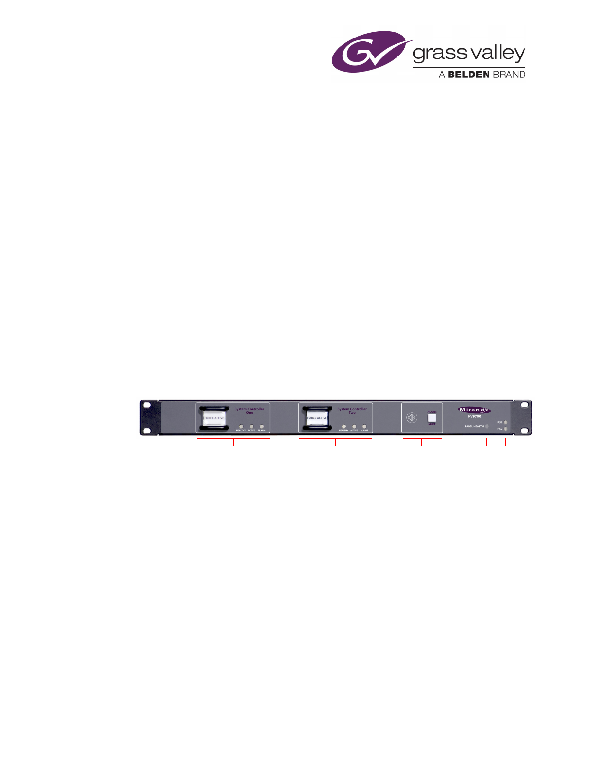
Switch and Status LEDs for
System Controller 1
Switch and Status LEDs for
System Controller 2
Buzzer and
Mute Switch
Panel
Health LED
Power Supply
LEDs
This brief guide describes the NV9700 Remote Diagnostic and Changeover Panel, a small and simple device that is part of a redundant NV9000 control system.
Please refer to the NV9000 documentation for information about NV9000 and its operation.
Introduction
The NV9700 is a slim 1RU device that allows an NV9000 operator these capabilities:
In addition, the NV9700 has a set of relay (GPO) outputs at the rear that can control fairly heavyduty external circuitry. The relays reflect the status conditions that are indicated at the front of the
panel. (See the Specifications
This is the front of the panel:
• See at a glance which NV9000 system controller is active.
• See at a glance whether an NV9000 system controller has an abnormal condition.
• Force a switch from one system controller to the other at any time.
• Hear an alert signal when an alarm condition occurs.
on page 10.)
There are two large push-button switches and 3 status LEDs for each of the two redundant system
controllers. Pressing the button forces the system active. The 3 LEDs indicate:
• Left, green LED
— system controller is “healthy.”
• Middle, amber LED — the system controller is active. Normally, one controller is active.
• Right, red LED
— the system controller has an alarm condition.
Buzzer
The front of the panel has an internal buzzer that sounds when an alarm condition arises. The
buzzer is behind the speaker icon imprinted on the panel. The buzzer can be disabled.
Next to the buzzer is a mute button. When the buzzer sounds and an operator responds to the alarm,
the operator may press the mute button to turn off the buzzer. (The mute is not a toggle. The buzzer
remains muted until another alarm condition occurs.)
Panel Health
At the right end of the panel are 3 more LEDs. Two represent the two (redundant) power supplies
and are illuminated when the power supply is connected and power is good. The remaining LED
NV9700 • User’s Guide 1
Page 2
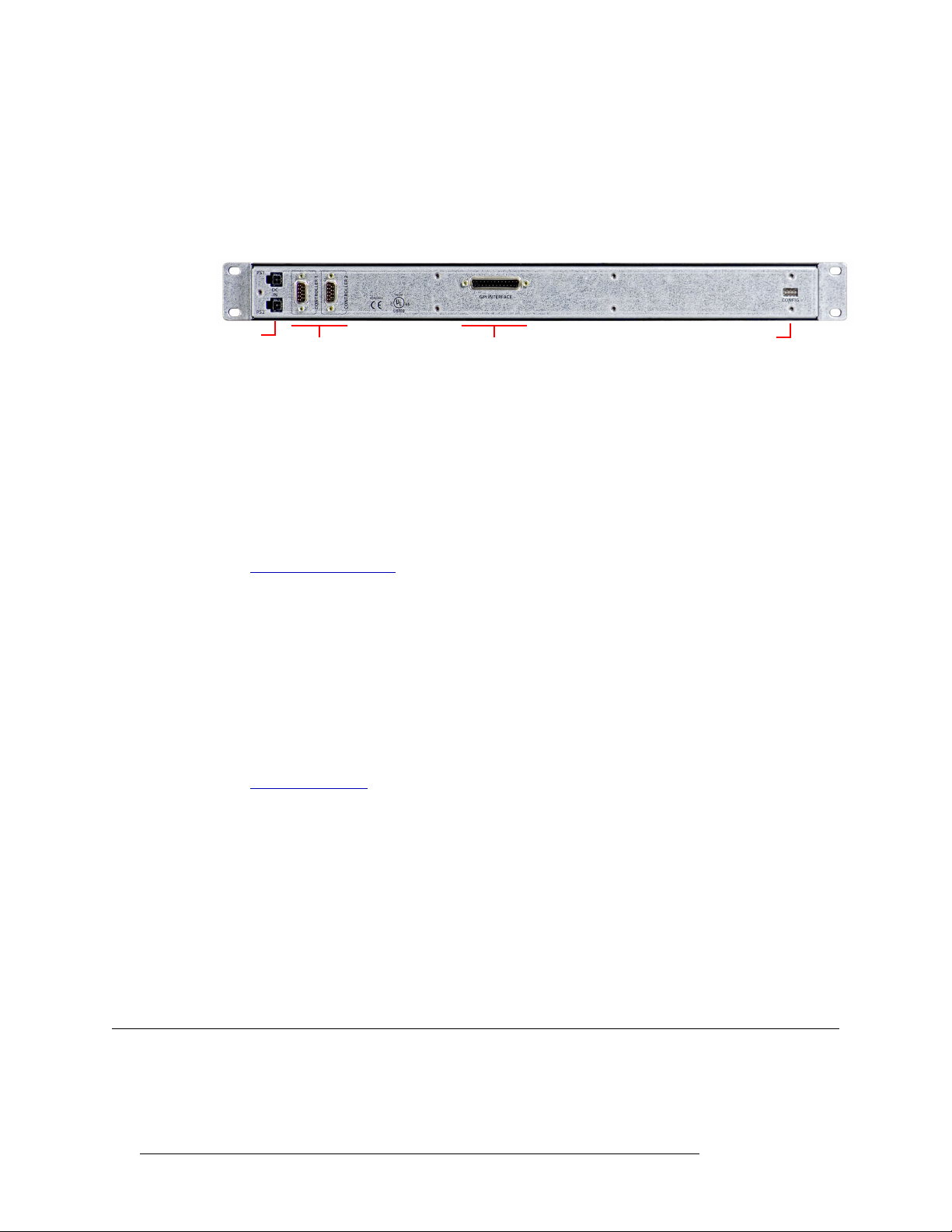
NV9700
Relay (GPO) Output
Connector
Controller
Connectors
DIP SwitchesPS1, PS2
Connections
(“Panel Health”) is green when the NV9700 itself is functioning properly and red if the NV9700 is
malfunctioning.
Panel Rear
This is a view of the rear of the panel:
At the left end are two power supply connectors. The NV9700 uses one or two PS0001 power sup-
— two for redundancy. The connectors are keyed 4-pin Molex connectors. It is not possible to
plies
connect the power supplies incorrectly. The connectors are labeled PS1 and PS2. LEDs on the front
of the panel are also labeled PS1 and PS2 and indicate whether a (good) power supply is connected.
Controller Connectors
Next to the power supply connectors are two DE9 connectors. These connect to the NV9000 system controllers. The protocol is RS-422.
See Controller Connections
for detail.
Relay Outputs
In the middle is a DB25 connector that supports relay output. The connector is labeled ‘GPI Interface’. (This is a bit of misnomer. The DB25 supports general-purpose outputs or GPOs.)
The connector presents 7 relay outputs:
• Three (health, active, alarm) for system controller 1.
• Three (health, active, alarm) for system controller 2.
• One (alarm) triggered when any alarm condition exists.
See Relay Connections
for detail.
DIP Switches
At the far right is an exposed set of DIP switches. There are 4 switches. The up position means the
switch is closed; the down position means the switch is open.
Switch 1 (on the left) enables the buzzer, when the switch is up.
Switch 4 (on the right) enables a technician to install new firmware in the panel. This switch should
be down under normal operation (and up to allow the firmware installation).
Switches 2 and 3 are unused at present.
Connections
For it to be useful, you must connect the NV9700 to both system controllers. You have the option of
using any or all of the relays to control external circuitry.
2 Rev 1.3 • 25 Nov 14
Page 3
NV9700
Connections
Controller Connections
The first step is to connect one serial (controller) port to one NV9000 system controller and the
other serial port to the other NV9000 system controller.
Each of the NV9000 system controllers must have a serial card installed. (There are several options
regarding the serial cards. Consult your service representative to determine your options.) Depending on the serial card installed in the NV9000, you will need either a straight-through serial cable or
a cross-over cable. See Cabling
These are two 8-port examples. There are other types of serial cards. In any case, the protocol is
RS-422, 9600 Baud, 8 data bits, 1 stop bit, no parity.
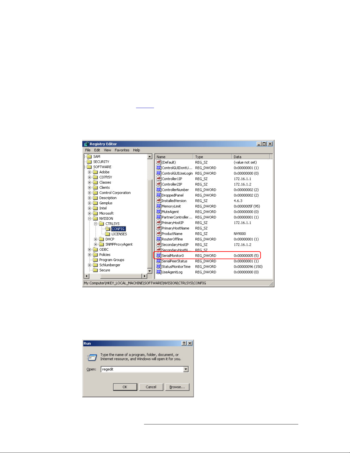
The second step is to create a registry variable in each of the NV9000 controllers:
, next page.
The registry variable allows the NV9000 software to monitor the serial port.
The variable is named
the NV97000 connection. In the preceding illustration, the port number is 5.
The numbering of the serial monitors starts at 0.
To launch the registry editor, choose ‘Run...’ from the Start menu, type ‘regedit’ and click OK:
Refer to the NV9000-SE Utilities User’s Guide for additional information.
NV9700 • User’s Guide 3
SerialMonitor0, a DWORD, and its value is the serial port number used by
Page 4

NV9700
1
5
9
6
Gnd
Tx
Rx +
Gnd
n.c.
Gnd
Tx +
Rx
Gnd
1
5
9
6
Rx
Tx
Tx +
Rx +
(RocketPort) Non-SMPTE
1
5
9
6
Tx +
Rx +
Rx
Tx
Moxa CP-118U and
other Moxa breakout
cables
1
5
9
6
Rx
Tx +
Tx
Gnd
Rx +
Grass Valley WC0153 cable
end for Moxa NPort 6650
Connections
Cabling
This is the pinout for each of the NV9700’s controller ports:
Depending on the serial card installed in your NV9000 controller, the DE9 ports to which you will
connect the NV9700 will have any of 3 pinouts:
Your cabling must accommodate the pinout. In all cases, Tx– connects to Rx– and Tx+ to Rx+.
(The NV9700’s ports are female. The serial card’s breakout ports might be either male or female.)
Making It Work
To make the NV9000 communicate with the NV9700 you must add the following registry entry:
\HKLM\SOFTWARE\NVISION/CTRLSYS/CONFIG/SerialMonitor0
The entry is a REG_DWORD and its value is that of COM port you are using for the NV9700. For
instance, the value is
Repeat this on the secondary system controller too if your NV9000 system is redundant.
Important: restart NVAGENT so it can detect the registry change.
In the general case, the registry entry is:
SerialMonitorN
where N is an integer starting at 0 and continuing contiguously until all the intended serial ports are
listed. When these keys are nonzero, the system controller listens for status and monitoring queries
on the port.
0x0000006 for COM port 6.
4 Rev 1.3 • 25 Nov 14
Page 5

NV9700
+ + + + + + +
121212
ActiveHealth AlarmBuzzer
13
1
14
25
+
Logic
External Power,
200V max, 130 mA max
+5V
Optical
Isolation
External lamp or load
External Ground
+
Discussion Points
Relay Connections
There are 7 relay outputs. Each can switch a fairly heavy load:
(Relay specifications are on page 10.)
Each relay has power (+) and ground (–) terminals on the DB25 connector. The DB25 connector
also has a number of additional ground terminals which you might want to connect to earth ground.
There are ‘alarm’ relays for controllers 1 and 2, ‘active’ relays for controllers 1 and 2, and ‘health’
relays for controllers 1 and 2. The relays are active when the LEDs are on and inactive when the
LEDs are off.
A seventh relay is analogous to the buzzer: that relay switches on during any alarm condition for
either controller and switches off if there is no alarm condition. Unlike the buzzer, the relay is not
deactivated by the mute button and is not enabled or disabled by a DIP switch.
Discussion Points
The NV9700 is a very simple device. It displays the status of your system controllers. It illuminates
an alarm LED when a system controller has a problem. If the buzzer is enabled, an alarm condition
sounds the buzzer. The buzzer continues to sound until someone mutes it.
When Failure Occurs
The NV9700 itself could fail. If the power supply LEDs are not illuminated, the panel has lost
power. If the ‘Panel Health’ LED is not illuminated, the NV9700 is malfunctioning. Ensure that the
NV9700 is powered up and functioning before continuing.
If a system controller fails (i.e., the red alarm LED is on), you will probably need to use the ‘System Management’ page of NV9000-SE Utilities to review system status and to restart system controllers.
Before doing anything else, check the obvious:
• Are the serial cables (between the NV9700 and the system controllers) connected?
• Are both system controllers powered up and running?
If both these conditions are met, and the alarms are still present, then you must perform further
NV9700 • User’s Guide 5
investigation to determine the cause of the failure and correct it.
Page 6

NV9700
Discussion Points
Failure Detection
The NV9000 has an watchdog timer that can be used to detect failures of the NV9700. Its use is
optional. To enable the watchdog, create a registry entry:
\HKLM\SOFTWARE\NVISION/CTRLSYS/CONFIG/SerialWatchdogEnable
This entry is a REG_DWORD. Set its value to 1 to enable the watchdog and set its value to 0 to disable
the watchdog. The time-out period is 100 ms. If the NV9000 does not receive a status poll from the
NV9700 every 100 ms, it signals a fault condition.
Failure Conditions
The following table lists the causes of failure (the reasons for the red alarm light to go on).
Condition Failover? Alarm?
Loss of communication between system controllers No
Failed network connection (hub, switch, or NIC) Yes Yes
Active system controller failed Yes Yes
Inactive system controller failed No Yes
Lost contact with a router (all types) Yes Yes
Lost contact with a (configurable) number of control panels Yes Yes
Lost contact with third-party external interface Not applicable
Solid state “hard drive” failed
(Spinning) hard disk failed No No
Lost 1 AC main or 1 power supply No No
Active system controller restarted Yes Yes
Inactive system controller restarted No Yes
Both system controllers restarted Yes Yes
Detection of system resource degradation Yes Yes
b
a
Ye s Ye s
Ye s
a. Both system controllers go active.
b. A solid state “hard drive” contains the operating system as well as data. A standard hard disk contains data only.
Routers have their own system and power alarms.
Details
Although not exhaustive, these points provide some detail regarding system failures:
• Loss of communication between system controllers.
A communication link between the two system controllers is required. That link can be a crossover Ethernet cable, straight cables with an Ethernet switch, or a serial connection.
If the cabling is absent or broken, or if an Ethernet switch is present and it malfunctions, each
system controller begins to operate as a stand-alone controller and attempts to operate as the
active controller. Eventually, one or both system controllers will malfunction in this condition.
Both ‘Active’ LEDs of the NV9700 go on. Both ‘Alarm’ LEDs go on. If you see this condition,
reconnect or replace the crossover cable.
• Failed network connection (hub, switch, or NIC).
6 Rev 1.3 • 25 Nov 14
Page 7

NV9700
Discussion Points
Any failed network will result in a fail-over and an alarm. (That includes the network supported
by the crossover cable.)
Generally, you will notice (in SE Utilities or in actuality) the failure of routers or panels in the
system at the same time or before you notice a hub failure.
If multiple routers or panels fail at the same time, it is probably that a hub, switch, or NIC failure occurred.
• Active system controller failed.
There are many reasons why a system controller could fail. In any case, such a failure results in
a fail-over and an alarm.
First, check whether the system controller is powered up and running. (Connect a keyboard,
mouse and monitor to verify that it is running properly.) If necessary, reboot the controller. That
will probably fix all but the most severe problems (such as a disk crash).
• Inactive system controller failed.
Again, there are many reasons why a system controller could fail. A fault in an inactive system
controller does not result in a fail-over but does generate an alarm.
Again, check whether the system controller is powered up and running. (Connect a keyboard,
mouse and monitor to verify that it is running properly.) If necessary, reboot the controller. That
will probably fix all but the most severe problems (such as a disk crash).
• Lost contact with a router (any and all types).
The system controller is otherwise healthy but either a router “died” or its network “died.” The
system fails over (in case it is a network failure) and generates an alarm.
Check the router’s power and control card(s) first. The control cards should show green
‘Health’ LEDs and one of the control cards should be active (the amber LED is illuminated). If
not, the router needs service.
If the router is healthy, the network is probably at fault. Check the hub or switch and the NIC.
• Lost contact with 2 or more control panels.
The system controller is otherwise healthy but two or more panels “died” or their network
“died.” (The problem is similar to a router failure, but the loss of a single panel is not considered a cause for alarm.) The system fails over (in case it is a network failure) and generates an
alarm.
Check power on all malfunctioning panels first. Restart any non-responsive panel that has good
power. If you get no response, either the panel needs service or the network has failed. Check
the hub or switch and the NIC.
• Lost contact with third-party external interface.
This condition
and alarms are not signaled.
• “Hard drive” failed.
A system controller will stop functioning or start malfunctioning if there is a hard drive failure.
If it stops functioning, the system fails over and generates an alarm. If the controller merely
malfunctions, the result is indeterminate. However, malfunctions typically cause the controller
to stop quickly.
If the drive is a solid state drive, it is possible that the operating system is corrupt. A reinstallation would be required.
— although serious — is not applicable to the NV9700. Fail-over does not occur
NV9700 • User’s Guide 7
Page 8

NV9700
Discussion Points
If the drive is a normal disk drive, data might be corrupt and a configuration reload would be
required.
It is also possible that the disk itself has been damaged.
Reboot the system controller. When you do, you will probably find out quickly what the problem is.
• Lost one AC main or one power supply.
Losing a single power supply or AC connection is not a cause for fail-over or an alarm unless it
is the only power source for the system controller.
The newer version of the NV9700 system controller will have a red lamp that indicates that one
of the two required power supplies has failed. The older NV9700s have an internal green LED
that does the same thing, but you might not be able to see it without dismantling the NV9700.
A fail-over occurs on full loss of power for the active controller and does not occur for the inactive controller.
The remedy might be as simple as plugging the AC cable back in. It is probable that the internal
power supply failed when you have AC power but the system controller still does not run.
• System controller restarted.
A restart of any system controller takes about 30 seconds. During that time, the controller is
effectively disconnected from the NV9700 and from NV9000-SE Utilities (from which you
must execute the restart).
Restarting the active controller causes a fail-over and an alarm.
Restarting the inactive controller does not cause a fail-over but does generate an alarm.
The alarm condition disappears after a successful restart (although the NV9700 buzzer might
continue to sound).
If you restart both system controllers at the same time (in NV9000-SE Utilities), system controller number 1 starts first and becomes active.
• Detection of system resource degradation.
Performance degradation is gradual. It is possible for the controller to degrade to a point at
which it can no longer function. The controller signals an alarm and the system fails over.
8 Rev 1.3 • 25 Nov 14
Page 9

1234
FORCE ACTIVE FORCE ACTIVE
PS1
PS2
9K50
E146905
DC
IN
GPI INTERFACE
CONFIG
CONTROLLER 2
CONTROLLER 1
19.0 [482.6]
17.23 [437.7]
0.19 [4.8]
0.61 [15.5]
1.15
[29.2]
1.95
[49.4]
1.72
[43.7]
Top View
Front View
Rear View
Drawings
The following drawing show the overall dimensions and features of the NV9700.
NV9700
Drawings
NV9700 • User’s Guide 9
Page 10

Specifications
Power Supply: PS0001-00. External, 12VDC at 2.5A.
Dimensions: 19.0″ W × 1.72″ H × 1.95″ D. [482.6 mm × 43.7 mm × 49.4 mm]
Weight: 1.69
Power: ≤ 4.5 W.
Relay limit: V
Buzzer: 4
Technical Support
Grass Valley has made every effort to ensure that the equipment you receive is in perfect working
order and that the equipment fits your needs. In the event that problems arise that you cannot
resolve, or if there are any questions regarding this equipment or information about other products
manufactured by Grass Valley, please contact your local representative or contact Grass Valley
directly through one of the appropriate means listed here.
• Main telephone: 514-333-1772 Website: http://www.grassvalley.com)
Fax: +1 514-333-9828
In the Americas, call toll-free: +1-800-547-8949 or +1 530 478 4148 (9 am to 9 pm EST)
In Europe, the Middle East, Africa, or the UK, call +44 118 952 3444 (9 am to 6 pm, GMT)
For playout automation, call +44 870 500 4350 (9 am to 5:30 pm, GMT)
In France, call +33 1 55 86 87 88 (9 am to 5 pm, GMT + 1)
In Asia, call +852-2539-6987 (9:30 am to 5 pm, GMT + 8)
In China, call +86-10-5873-1814 (9:30 am to 5 pm, GMT + 8)
In Malaysia, call +60 3 2247 1808
•E-Mail:
In the Americas, support@grass valley.com
In Europe, the Middle East, Africa, or the UK, eurotech@grass valley.com
For playout automation, automationsupport@grass valley.com
In France, eurotech@grass valley.com
In Asia, asiatech@grass valley.com
In China, asiatech@grass valley.com
In Malaysia, asiatech@grass valley.com
•Mail
Grass Valley
3499 Douglas B. Floreani
Montreal, Quebec
Canada H4S 2C6
lb [0.765 kg].
(output dielectric strength) ≤ 200 V
OFF
Continuous load current ≤ 200 mA
Recommended operation:
Load current < 130 mA
V
< 200 V
OFF
kHz; 87 dB at 12 VDC.
NV9700
Specifications
Note Return Material Authorization (RMA) required for all returns.
10 Rev 1.3 • 25 Nov 14
 Loading...