

Page 1

NV9654
NV9000 Control Panel
User’s Guide
UG0077-01
20 Nov 2014
Page 2

Copyright & Trademark Notice
Copyright © 2014 Grass Valley. All rights reserved.
Belden, Belden Sending All The Right Signals, and the Belden logo are trademarks or
registered trademarks of Belden Inc. or its affiliated companies in the United States and
other jurisdictions. Grass Valley, NVISION, NV9000, and NV9654 are trademarks or registered
trademarks of Grass Valley. Belden Inc., Grass Valley, and other parties may also have
trademark rights in other terms used herein.
Terms and Conditions
Please read the following terms and conditions carefully. By using NV9654 documentation,
you agree to the following terms and conditions.
Grass Valley hereby grants permission and license to owners of NV9654 routers to use their
product manuals for their own internal business use. Manuals for Grass Valley products may
not be reproduced or transmitted in any form or by any means, electronic or mechanical,
including photocopying and recording, for any purpose unless specifically authorized in
writing by Grass Valley.
A Grass Valley manual may have been revised to reflect changes made to the product during
its manufacturing life. Thus, different versions of a manual may exist for any given product.
Care should be taken to ensure that one obtains the proper manual version for a specific
product serial number.
Information in this document is subject to change without notice and does not represent a
commitment on the part of Grass Valley.
Warranty information is available in the support section of the Grass Valley web site
(www.grassvalley.com).
Title NV9654 Control Panel User’s Guide
Part Number UG0077-01
Revision 1.1 (20 Nov 14)
ii
Page 3
Change History
Rev. Date ECO Description Approved
1.0 24 Apr 13 18826 Initial release D.Cox
1.1 20 Nov 14 19357 New format. Added Korean compliance statement.
Safety Compliance
Korean Compliance (KCC) Statement
이 기기는 업무용 (A 급 ) 전자파적합기기로서 판
매자
또는 사용자는 이 점을 주의하시기 바라
며
, 가정외의 지역에서 사용하는 것을 목적으로
합니다
Please note this is a Class A device. Sellers or users need to take note of this and should not
use this equipment in a domestic environment.
.
Revisions to selection buttons and the edit
navigation button dialog.
KCC-REM-XEI-NV8500
급 기기
A
( 업무용 방송통신 기자재 )
Class A Equipment
(Commercial Broadcasting & Communication Equipment)
NV9654
User’s Guide
D.Cox
FCC Statement
This equipment has been tested and found to comply with the limits for a Class A digital
device, pursuant to part 15 of the FCC Rules. These limits are designed to provide reasonable
protection against harmful interference when the equipment is operated in a commercial
environment. This equipment generates, uses, and can radiate radio frequency energy and,
if not installed and used in accordance with the instruction manual, may cause harmful
interference to radio communications. Operation of this equipment in a residential area is
likely to cause harmful interference in which case the user will be required to correct the
interference at his own expense.
Declaration of Conformance (CE)
All of the equipment described in this manual has been designed to conform with the
required safety and emissions standards of the European Community. Products tested and
verified to meet these standards are marked as required by law with the CE mark.
When shipped into member countries of the European Community, this equipment is
accompanied by authentic copies of original Declarations of Conformance on file in the
Grass Valley offices in Grass Valley, California USA.
Software License Agreement and Warranty Information
Contact Grass Valley for details on the software license agreement and product warranty.
iii
Page 4

Important Safeguards and Notices
This section provides important safety guidelines for operators and service personnel.
Specific warnings and cautions appear throughout the manual where they apply. Please
read and follow this important information, especially those instructions related to the risk
of electric shock or injury to persons.
WAR NIN G
Any instructions in this manual that require opening the equipment cover or enclosure are
for use by qualified service personnel only. To reduce the risk of electric shock, do not
perform any service other than that contained in the operating instructions unless you are
qualified to do so.
Restriction on Hazardous Substances (RoHs)
Grass Valley is in compliance with EU Directive RoHS 2002/95/EC governing the restricted
use of certain hazardous substances and materials in products and in our manufacturing
processes.
Grass Valley has a substantial program in place for RoHS compliance that includes significant
investment in our manufacturing process, and a migration of Grass Valley product electronic
components and structural materials to RoHS compliance.
It is our objective at Grass Valley to maintain compliance with all relevant environmental and
product regulatory requirements. Detailed information on specific products or on the RoHS
program at Grass Valley is available from Grass Valley Customer Support at
1-800-719-1900 (toll-free) or
1-530-265-1000 (outside the U.S.).
iv
Page 5
Symbols and Their Meanings
The lightning flash with arrowhead symbol within an equilateral triangle alerts the
user to the presence of dangerous voltages within the product’s enclosure that
may be of sufficient magnitude to constitute a risk of electric shock to persons.
The exclamation point within an equilateral triangle alerts the user to the presence
of important operating and maintenance/service instructions.
The Ground symbol represents a protective grounding terminal. Such a terminal
must be connected to earth ground prior to making any other connections to the
equipment.
The fuse symbol indicates that the fuse referenced in the text must be replaced
with one having the ratings indicated.
NV9654
User’s Guide
The presence of this symbol in or on Grass Valley equipment means that it has been
designed, tested and certified as complying with applicable Underwriter’s
Laboratory (USA) regulations and recommendations.
The presence of this symbol in or on Grass Valley equipment means that it has been
designed, tested and certified as essentially complying with all applicable
European Union (CE) regulations and recommendations.
General Warnings
A warning indicates a possible hazard to personnel which may cause injury or death.
Observe the following general warnings when using or working on this equipment:
• Heed all warnings on the unit and in the operating instructions.
• Do not use this equipment in or near water.
• This equipment is grounded through the grounding conductor of the power cord. To
avoid electrical shock, plug the power cord into a properly wired receptacle before connecting the equipment inputs or outputs.
• Route power cords and other cables so they are not likely to be damaged.
• Disconnect power before cleaning the equipment. Do not use liquid or aerosol cleaners; use only a damp cloth.
• Dangerous voltages may exist at several points in this equipment. To avoid injury, do
not touch exposed connections and components while power is on.
• Do not wear rings or wristwatches when troubleshooting high current circuits such as
the power supplies.
v
Page 6

• To avoid fire hazard, use only the specified fuse(s) with the correct type number, voltage
and current ratings as referenced in the appropriate locations in the service instructions or on the equipment. Always refer fuse replacements to qualified service personnel.
• To avoid explosion, do not operate this equipment in an explosive atmosphere.
• Have qualified service personnel perform safety checks after any service.
General Cautions
A caution indicates a possible hazard to equipment that could result in equipment damage.
Observe the following cautions when operating or working on this equipment:
• When installing this equipment, do not attach the power cord to building surfaces.
• To prevent damage to equipment when replacing fuses, locate and correct the problem
that caused the fuse to blow before re-applying power.
• Use only the specified replacement parts.
• Follow static precautions at all times when handling this equipment.
• This product should only be powered as described in the manual. To prevent equipment damage, select the proper line voltage on the power supply(ies) as described in
the installation documentation.
• To prevent damage to the equipment, read the instructions in the equipment manual
for proper input voltage range selection.
• Some products include a backup battery. There is a risk of explosion if the battery is
replaced by a battery of an incorrect type. Dispose of batteries according to instructions.
• Products that have (1) no on/off switch and (2) use an external power supply must be
installed in proximity to a main power outlet that is easily accessible.
• To reduce the risk of electrical shock, plug each power supply cord into a separate
branch circuit having a separate service ground.
vi
Page 7

Table of Contents
1 Preface . . . . . . . . . . . . . . . . . . . . . . . . . . . . . . . . . . . . . . . . . . . . . . . . 1
Chapter Structure . . . . . . . . . . . . . . . . . . . . . . . . . . . . . . . . . . . . . . . . . . . . . . . . . . . . . . . . . . . . . . . . . . . . . . . . . . . . . . 1
The PDF Document . . . . . . . . . . . . . . . . . . . . . . . . . . . . . . . . . . . . . . . . . . . . . . . . . . . . . . . . . . . . . . . . . . . . . . . . . . . . . 1
Terms, Conventions and Abbreviations . . . . . . . . . . . . . . . . . . . . . . . . . . . . . . . . . . . . . . . . . . . . . . . . . . . . . . . . . . 2
Other Documentation and Software . . . . . . . . . . . . . . . . . . . . . . . . . . . . . . . . . . . . . . . . . . . . . . . . . . . . . . . . . . . . 2
2 Introduction . . . . . . . . . . . . . . . . . . . . . . . . . . . . . . . . . . . . . . . . . . . 3
Summary . . . . . . . . . . . . . . . . . . . . . . . . . . . . . . . . . . . . . . . . . . . . . . . . . . . . . . . . . . . . . . . . . . . . . . . . . . . . . . . . . . . . . . . 3
Panel Organization . . . . . . . . . . . . . . . . . . . . . . . . . . . . . . . . . . . . . . . . . . . . . . . . . . . . . . . . . . . . . . . . . . . . . . . . . . . . . 4
Function Buttons. . . . . . . . . . . . . . . . . . . . . . . . . . . . . . . . . . . . . . . . . . . . . . . . . . . . . . . . . . . . . . . . . . . . . . . . . . . 4
Alphanumeric Display . . . . . . . . . . . . . . . . . . . . . . . . . . . . . . . . . . . . . . . . . . . . . . . . . . . . . . . . . . . . . . . . . . . . . . 5
Display Fields . . . . . . . . . . . . . . . . . . . . . . . . . . . . . . . . . . . . . . . . . . . . . . . . . . . . . . . . . . . . . . . . . . . . . . . . . 6
Tally Interface . . . . . . . . . . . . . . . . . . . . . . . . . . . . . . . . . . . . . . . . . . . . . . . . . . . . . . . . . . . . . . . . . . . . . . . . . . . . . 8
Modes of Operation. . . . . . . . . . . . . . . . . . . . . . . . . . . . . . . . . . . . . . . . . . . . . . . . . . . . . . . . . . . . . . . . . . . . . . . . . . . . . 8
Other NV9654 Functions . . . . . . . . . . . . . . . . . . . . . . . . . . . . . . . . . . . . . . . . . . . . . . . . . . . . . . . . . . . . . . . . . . . . . . . . 9
3 Installation. . . . . . . . . . . . . . . . . . . . . . . . . . . . . . . . . . . . . . . . . . . . 11
Package Contents . . . . . . . . . . . . . . . . . . . . . . . . . . . . . . . . . . . . . . . . . . . . . . . . . . . . . . . . . . . . . . . . . . . . . . . . . . . . . 11
Installation . . . . . . . . . . . . . . . . . . . . . . . . . . . . . . . . . . . . . . . . . . . . . . . . . . . . . . . . . . . . . . . . . . . . . . . . . . . . . . . . . . . . 12
Installing Software and Documentation. . . . . . . . . . . . . . . . . . . . . . . . . . . . . . . . . . . . . . . . . . . . . . . . . . . . . . . . . 12
Initialization . . . . . . . . . . . . . . . . . . . . . . . . . . . . . . . . . . . . . . . . . . . . . . . . . . . . . . . . . . . . . . . . . . . . . . . . . . . . . . . . . . . 13
Testing . . . . . . . . . . . . . . . . . . . . . . . . . . . . . . . . . . . . . . . . . . . . . . . . . . . . . . . . . . . . . . . . . . . . . . . . . . . . . . . . . . . . . . . . 14
4 Configuration . . . . . . . . . . . . . . . . . . . . . . . . . . . . . . . . . . . . . . . . . 15
Summary . . . . . . . . . . . . . . . . . . . . . . . . . . . . . . . . . . . . . . . . . . . . . . . . . . . . . . . . . . . . . . . . . . . . . . . . . . . . . . . . . . . . . . 15
Adding a Panel to an NV9000 Configuration . . . . . . . . . . . . . . . . . . . . . . . . . . . . . . . . . . . . . . . . . . . . . . . . . . . . 15
NV9654 Panel Configuration Page . . . . . . . . . . . . . . . . . . . . . . . . . . . . . . . . . . . . . . . . . . . . . . . . . . . . . . . . . . . . . . 18
Regions of the Configuration Page. . . . . . . . . . . . . . . . . . . . . . . . . . . . . . . . . . . . . . . . . . . . . . . . . . . . . . . . . 19
Configuration Tasks . . . . . . . . . . . . . . . . . . . . . . . . . . . . . . . . . . . . . . . . . . . . . . . . . . . . . . . . . . . . . . . . . . . . . . . 20
Commitment Buttons . . . . . . . . . . . . . . . . . . . . . . . . . . . . . . . . . . . . . . . . . . . . . . . . . . . . . . . . . . . . . . . . . . . . . . . . . 21
Panel Options. . . . . . . . . . . . . . . . . . . . . . . . . . . . . . . . . . . . . . . . . . . . . . . . . . . . . . . . . . . . . . . . . . . . . . . . . . . . . . . . . . 21
Checkbox Options . . . . . . . . . . . . . . . . . . . . . . . . . . . . . . . . . . . . . . . . . . . . . . . . . . . . . . . . . . . . . . . . . . . . . . . . 23
Button Definitions . . . . . . . . . . . . . . . . . . . . . . . . . . . . . . . . . . . . . . . . . . . . . . . . . . . . . . . . . . . . . . . . . . . . . . . . . . . . . 25
Button Specification. . . . . . . . . . . . . . . . . . . . . . . . . . . . . . . . . . . . . . . . . . . . . . . . . . . . . . . . . . . . . . . . . . . . . . . 26
Button Types . . . . . . . . . . . . . . . . . . . . . . . . . . . . . . . . . . . . . . . . . . . . . . . . . . . . . . . . . . . . . . . . . . . . . . . . . . . . . 27
‘Edit Navigation Button’ Dialog . . . . . . . . . . . . . . . . . . . . . . . . . . . . . . . . . . . . . . . . . . . . . . . . . . . . . . . . . . . . 34
Automatic Fill Options . . . . . . . . . . . . . . . . . . . . . . . . . . . . . . . . . . . . . . . . . . . . . . . . . . . . . . . . . . . . . . . . 35
Button Page List . . . . . . . . . . . . . . . . . . . . . . . . . . . . . . . . . . . . . . . . . . . . . . . . . . . . . . . . . . . . . . . . . . . . . . . . . . . . . . . 37
Tally (GPIO) Window . . . . . . . . . . . . . . . . . . . . . . . . . . . . . . . . . . . . . . . . . . . . . . . . . . . . . . . . . . . . . . . . . . . . . . . . . . . 38
Selection Buttons . . . . . . . . . . . . . . . . . . . . . . . . . . . . . . . . . . . . . . . . . . . . . . . . . . . . . . . . . . . . . . . . . . . . . . . . . . . . . . 38
Scrolling . . . . . . . . . . . . . . . . . . . . . . . . . . . . . . . . . . . . . . . . . . . . . . . . . . . . . . . . . . . . . . . . . . . . . . . . . . . . . . . . . . 39
vii
Page 8

Table of Contents
Selection Button Behavior . . . . . . . . . . . . . . . . . . . . . . . . . . . . . . . . . . . . . . . . . . . . . . . . . . . . . . . . . . . . . . . . . 40
XY Mode . . . . . . . . . . . . . . . . . . . . . . . . . . . . . . . . . . . . . . . . . . . . . . . . . . . . . . . . . . . . . . . . . . . . . . . . . . . . . 40
MD Mode . . . . . . . . . . . . . . . . . . . . . . . . . . . . . . . . . . . . . . . . . . . . . . . . . . . . . . . . . . . . . . . . . . . . . . . . . . . . 40
Populating the MD Device List . . . . . . . . . . . . . . . . . . . . . . . . . . . . . . . . . . . . . . . . . . . . . . . . . . . . . . . . 40
Selection. . . . . . . . . . . . . . . . . . . . . . . . . . . . . . . . . . . . . . . . . . . . . . . . . . . . . . . . . . . . . . . . . . . . . . . . . . . . . . . . . . 40
XY Mode
XY Mode — Hold Mode . . . . . . . . . . . . . . . . . . . . . . . . . . . . . . . . . . . . . . . . . . . . . . . . . . . . . . . . . . . . . . 41
MD Mode — Normal . . . . . . . . . . . . . . . . . . . . . . . . . . . . . . . . . . . . . . . . . . . . . . . . . . . . . . . . . . . . . . . . . 41
MD Mode
Display Indexes . . . . . . . . . . . . . . . . . . . . . . . . . . . . . . . . . . . . . . . . . . . . . . . . . . . . . . . . . . . . . . . . . . . . . . . . . . . 41
Single-Destination Mode . . . . . . . . . . . . . . . . . . . . . . . . . . . . . . . . . . . . . . . . . . . . . . . . . . . . . . . . . . . . . . . . . . . . . . 41
Multi-Destination Configuration . . . . . . . . . . . . . . . . . . . . . . . . . . . . . . . . . . . . . . . . . . . . . . . . . . . . . . . . . . . . . . . 42
How to Configure MD Devices . . . . . . . . . . . . . . . . . . . . . . . . . . . . . . . . . . . . . . . . . . . . . . . . . . . . . . . . . . . . . 42
MD Destination Options . . . . . . . . . . . . . . . . . . . . . . . . . . . . . . . . . . . . . . . . . . . . . . . . . . . . . . . . . . . . . . . . . . . 44
User-Definable . . . . . . . . . . . . . . . . . . . . . . . . . . . . . . . . . . . . . . . . . . . . . . . . . . . . . . . . . . . . . . . . . . . . . . . 44
User-Selectable. . . . . . . . . . . . . . . . . . . . . . . . . . . . . . . . . . . . . . . . . . . . . . . . . . . . . . . . . . . . . . . . . . . . . . . 44
Global Navigation . . . . . . . . . . . . . . . . . . . . . . . . . . . . . . . . . . . . . . . . . . . . . . . . . . . . . . . . . . . . . . . . . . . . . . . . . . . . . 44
Names . . . . . . . . . . . . . . . . . . . . . . . . . . . . . . . . . . . . . . . . . . . . . . . . . . . . . . . . . . . . . . . . . . . . . . . . . . . . . . . . . . . . 45
Referencing a Suffix Template . . . . . . . . . . . . . . . . . . . . . . . . . . . . . . . . . . . . . . . . . . . . . . . . . . . . . . . . . . . . . 45
Referencing a Navigate Template . . . . . . . . . . . . . . . . . . . . . . . . . . . . . . . . . . . . . . . . . . . . . . . . . . . . . . . . . 46
Composing Suffix Templates . . . . . . . . . . . . . . . . . . . . . . . . . . . . . . . . . . . . . . . . . . . . . . . . . . . . . . . . . . . . . . 47
Template Changes . . . . . . . . . . . . . . . . . . . . . . . . . . . . . . . . . . . . . . . . . . . . . . . . . . . . . . . . . . . . . . . . . . . 47
Composing Navigate Templates . . . . . . . . . . . . . . . . . . . . . . . . . . . . . . . . . . . . . . . . . . . . . . . . . . . . . . . . . . . 48
Template Changes . . . . . . . . . . . . . . . . . . . . . . . . . . . . . . . . . . . . . . . . . . . . . . . . . . . . . . . . . . . . . . . . . . . 48
— Normal . . . . . . . . . . . . . . . . . . . . . . . . . . . . . . . . . . . . . . . . . . . . . . . . . . . . . . . . . . . . . . . . . . 40
— Hold Mode . . . . . . . . . . . . . . . . . . . . . . . . . . . . . . . . . . . . . . . . . . . . . . . . . . . . . . . . . . . . . . 41
5 Operation. . . . . . . . . . . . . . . . . . . . . . . . . . . . . . . . . . . . . . . . . . . . . 51
Summary . . . . . . . . . . . . . . . . . . . . . . . . . . . . . . . . . . . . . . . . . . . . . . . . . . . . . . . . . . . . . . . . . . . . . . . . . . . . . . . . . . . . . . 51
Modes of Operation . . . . . . . . . . . . . . . . . . . . . . . . . . . . . . . . . . . . . . . . . . . . . . . . . . . . . . . . . . . . . . . . . . . . . . . 52
Behavioral Models . . . . . . . . . . . . . . . . . . . . . . . . . . . . . . . . . . . . . . . . . . . . . . . . . . . . . . . . . . . . . . . . . . . . . . . . 53
Button Legends . . . . . . . . . . . . . . . . . . . . . . . . . . . . . . . . . . . . . . . . . . . . . . . . . . . . . . . . . . . . . . . . . . . . . . . . . . . 53
Levels on Selection Buttons. . . . . . . . . . . . . . . . . . . . . . . . . . . . . . . . . . . . . . . . . . . . . . . . . . . . . . . . . . . . . . . . 53
Level Mapping . . . . . . . . . . . . . . . . . . . . . . . . . . . . . . . . . . . . . . . . . . . . . . . . . . . . . . . . . . . . . . . . . . . . . . . 55
MD Devices on Selection Buttons . . . . . . . . . . . . . . . . . . . . . . . . . . . . . . . . . . . . . . . . . . . . . . . . . . . . . . . . . . 55
Lists . . . . . . . . . . . . . . . . . . . . . . . . . . . . . . . . . . . . . . . . . . . . . . . . . . . . . . . . . . . . . . . . . . . . . . . . . . . . . . . . . . . . . . 56
Operating Concepts. . . . . . . . . . . . . . . . . . . . . . . . . . . . . . . . . . . . . . . . . . . . . . . . . . . . . . . . . . . . . . . . . . . . . . . . . . . . 57
Levels . . . . . . . . . . . . . . . . . . . . . . . . . . . . . . . . . . . . . . . . . . . . . . . . . . . . . . . . . . . . . . . . . . . . . . . . . . . . . . . . . . . . 57
Breakaway . . . . . . . . . . . . . . . . . . . . . . . . . . . . . . . . . . . . . . . . . . . . . . . . . . . . . . . . . . . . . . . . . . . . . . . . . . . 57
Level Grouping . . . . . . . . . . . . . . . . . . . . . . . . . . . . . . . . . . . . . . . . . . . . . . . . . . . . . . . . . . . . . . . . . . . . . . . 57
Hold . . . . . . . . . . . . . . . . . . . . . . . . . . . . . . . . . . . . . . . . . . . . . . . . . . . . . . . . . . . . . . . . . . . . . . . . . . . . . . . . . . . . . . 58
Breakaway . . . . . . . . . . . . . . . . . . . . . . . . . . . . . . . . . . . . . . . . . . . . . . . . . . . . . . . . . . . . . . . . . . . . . . . . . . . 58
Multi-Destination Mode . . . . . . . . . . . . . . . . . . . . . . . . . . . . . . . . . . . . . . . . . . . . . . . . . . . . . . . . . . . . . . 58
Category Selection . . . . . . . . . . . . . . . . . . . . . . . . . . . . . . . . . . . . . . . . . . . . . . . . . . . . . . . . . . . . . . . . . . . . . . . . 58
Buttons . . . . . . . . . . . . . . . . . . . . . . . . . . . . . . . . . . . . . . . . . . . . . . . . . . . . . . . . . . . . . . . . . . . . . . . . . . . . . . . . . . . 59
Back . . . . . . . . . . . . . . . . . . . . . . . . . . . . . . . . . . . . . . . . . . . . . . . . . . . . . . . . . . . . . . . . . . . . . . . . . . . . . . . . . 59
Broadcast . . . . . . . . . . . . . . . . . . . . . . . . . . . . . . . . . . . . . . . . . . . . . . . . . . . . . . . . . . . . . . . . . . . . . . . . . . . . 59
Category . . . . . . . . . . . . . . . . . . . . . . . . . . . . . . . . . . . . . . . . . . . . . . . . . . . . . . . . . . . . . . . . . . . . . . . . . . . . 60
Chop . . . . . . . . . . . . . . . . . . . . . . . . . . . . . . . . . . . . . . . . . . . . . . . . . . . . . . . . . . . . . . . . . . . . . . . . . . . . . . . . 60
Clear Preset . . . . . . . . . . . . . . . . . . . . . . . . . . . . . . . . . . . . . . . . . . . . . . . . . . . . . . . . . . . . . . . . . . . . . . . . . . 61
Default State . . . . . . . . . . . . . . . . . . . . . . . . . . . . . . . . . . . . . . . . . . . . . . . . . . . . . . . . . . . . . . . . . . . . . . . . . 61
Destination . . . . . . . . . . . . . . . . . . . . . . . . . . . . . . . . . . . . . . . . . . . . . . . . . . . . . . . . . . . . . . . . . . . . . . . . . . 61
Destination Lock . . . . . . . . . . . . . . . . . . . . . . . . . . . . . . . . . . . . . . . . . . . . . . . . . . . . . . . . . . . . . . . . . . . . . 61
Destination Protect . . . . . . . . . . . . . . . . . . . . . . . . . . . . . . . . . . . . . . . . . . . . . . . . . . . . . . . . . . . . . . . . . . 62
Free Source . . . . . . . . . . . . . . . . . . . . . . . . . . . . . . . . . . . . . . . . . . . . . . . . . . . . . . . . . . . . . . . . . . . . . . . . . . 62
Forward . . . . . . . . . . . . . . . . . . . . . . . . . . . . . . . . . . . . . . . . . . . . . . . . . . . . . . . . . . . . . . . . . . . . . . . . . . . . . 62
Hold . . . . . . . . . . . . . . . . . . . . . . . . . . . . . . . . . . . . . . . . . . . . . . . . . . . . . . . . . . . . . . . . . . . . . . . . . . . . . . . . . 63
viii
Page 9

Information . . . . . . . . . . . . . . . . . . . . . . . . . . . . . . . . . . . . . . . . . . . . . . . . . . . . . . . . . . . . . . . . . . . . . . . . . . 63
Level Map . . . . . . . . . . . . . . . . . . . . . . . . . . . . . . . . . . . . . . . . . . . . . . . . . . . . . . . . . . . . . . . . . . . . . . . . . . . 63
Menu . . . . . . . . . . . . . . . . . . . . . . . . . . . . . . . . . . . . . . . . . . . . . . . . . . . . . . . . . . . . . . . . . . . . . . . . . . . . . . . . 65
Name Set Toggle . . . . . . . . . . . . . . . . . . . . . . . . . . . . . . . . . . . . . . . . . . . . . . . . . . . . . . . . . . . . . . . . . . . . . 65
Navigate . . . . . . . . . . . . . . . . . . . . . . . . . . . . . . . . . . . . . . . . . . . . . . . . . . . . . . . . . . . . . . . . . . . . . . . . . . . . . 66
Global Navigate . . . . . . . . . . . . . . . . . . . . . . . . . . . . . . . . . . . . . . . . . . . . . . . . . . . . . . . . . . . . . . . . . . . . . . 66
Page Down . . . . . . . . . . . . . . . . . . . . . . . . . . . . . . . . . . . . . . . . . . . . . . . . . . . . . . . . . . . . . . . . . . . . . . . . . . 66
Page Up . . . . . . . . . . . . . . . . . . . . . . . . . . . . . . . . . . . . . . . . . . . . . . . . . . . . . . . . . . . . . . . . . . . . . . . . . . . . . 67
Panel Lock . . . . . . . . . . . . . . . . . . . . . . . . . . . . . . . . . . . . . . . . . . . . . . . . . . . . . . . . . . . . . . . . . . . . . . . . . . . 67
Preset Release . . . . . . . . . . . . . . . . . . . . . . . . . . . . . . . . . . . . . . . . . . . . . . . . . . . . . . . . . . . . . . . . . . . . . . . 67
Previous Source . . . . . . . . . . . . . . . . . . . . . . . . . . . . . . . . . . . . . . . . . . . . . . . . . . . . . . . . . . . . . . . . . . . . . . 67
Quick Source . . . . . . . . . . . . . . . . . . . . . . . . . . . . . . . . . . . . . . . . . . . . . . . . . . . . . . . . . . . . . . . . . . . . . . . . 67
Salvo . . . . . . . . . . . . . . . . . . . . . . . . . . . . . . . . . . . . . . . . . . . . . . . . . . . . . . . . . . . . . . . . . . . . . . . . . . . . . . . . 68
Save Preset . . . . . . . . . . . . . . . . . . . . . . . . . . . . . . . . . . . . . . . . . . . . . . . . . . . . . . . . . . . . . . . . . . . . . . . . . . 68
Selection Buttons . . . . . . . . . . . . . . . . . . . . . . . . . . . . . . . . . . . . . . . . . . . . . . . . . . . . . . . . . . . . . . . . . . . . 68
Source . . . . . . . . . . . . . . . . . . . . . . . . . . . . . . . . . . . . . . . . . . . . . . . . . . . . . . . . . . . . . . . . . . . . . . . . . . . . . . . 70
Source/Destination . . . . . . . . . . . . . . . . . . . . . . . . . . . . . . . . . . . . . . . . . . . . . . . . . . . . . . . . . . . . . . . . . . 71
Source is Master . . . . . . . . . . . . . . . . . . . . . . . . . . . . . . . . . . . . . . . . . . . . . . . . . . . . . . . . . . . . . . . . . . . . . . 71
Take . . . . . . . . . . . . . . . . . . . . . . . . . . . . . . . . . . . . . . . . . . . . . . . . . . . . . . . . . . . . . . . . . . . . . . . . . . . . . . . . . 71
Undefined . . . . . . . . . . . . . . . . . . . . . . . . . . . . . . . . . . . . . . . . . . . . . . . . . . . . . . . . . . . . . . . . . . . . . . . . . . . 71
Toggle Display . . . . . . . . . . . . . . . . . . . . . . . . . . . . . . . . . . . . . . . . . . . . . . . . . . . . . . . . . . . . . . . . . . . . . . . 71
‘VFD/Sel Paging Toggle’ . . . . . . . . . . . . . . . . . . . . . . . . . . . . . . . . . . . . . . . . . . . . . . . . . . . . . . . . . . . . . . 71
X-Y Display . . . . . . . . . . . . . . . . . . . . . . . . . . . . . . . . . . . . . . . . . . . . . . . . . . . . . . . . . . . . . . . . . . . . . . . . . . 72
XY/MD Mode . . . . . . . . . . . . . . . . . . . . . . . . . . . . . . . . . . . . . . . . . . . . . . . . . . . . . . . . . . . . . . . . . . . . . . . . 72
Lock, Protect, and Release . . . . . . . . . . . . . . . . . . . . . . . . . . . . . . . . . . . . . . . . . . . . . . . . . . . . . . . . . . . . . . . . . 72
Takes . . . . . . . . . . . . . . . . . . . . . . . . . . . . . . . . . . . . . . . . . . . . . . . . . . . . . . . . . . . . . . . . . . . . . . . . . . . . . . . . . . . . . 73
XY Mode . . . . . . . . . . . . . . . . . . . . . . . . . . . . . . . . . . . . . . . . . . . . . . . . . . . . . . . . . . . . . . . . . . . . . . . . . . . . . 73
Single-Destination Panel . . . . . . . . . . . . . . . . . . . . . . . . . . . . . . . . . . . . . . . . . . . . . . . . . . . . . . . . . . . . . 73
MD Mode . . . . . . . . . . . . . . . . . . . . . . . . . . . . . . . . . . . . . . . . . . . . . . . . . . . . . . . . . . . . . . . . . . . . . . . . . . . . 73
Name Sets . . . . . . . . . . . . . . . . . . . . . . . . . . . . . . . . . . . . . . . . . . . . . . . . . . . . . . . . . . . . . . . . . . . . . . . . . . . . . . . . 74
Broadcast Routes . . . . . . . . . . . . . . . . . . . . . . . . . . . . . . . . . . . . . . . . . . . . . . . . . . . . . . . . . . . . . . . . . . . . . . . . . 74
Making Broadcast Routes . . . . . . . . . . . . . . . . . . . . . . . . . . . . . . . . . . . . . . . . . . . . . . . . . . . . . . . . . . . . . 74
Removing Broadcast Routes . . . . . . . . . . . . . . . . . . . . . . . . . . . . . . . . . . . . . . . . . . . . . . . . . . . . . . . . . . 75
Data Routing. . . . . . . . . . . . . . . . . . . . . . . . . . . . . . . . . . . . . . . . . . . . . . . . . . . . . . . . . . . . . . . . . . . . . . . . . . . . . . 75
Automatic Data Routing . . . . . . . . . . . . . . . . . . . . . . . . . . . . . . . . . . . . . . . . . . . . . . . . . . . . . . . . . . . . . . 75
Manual Data Routing . . . . . . . . . . . . . . . . . . . . . . . . . . . . . . . . . . . . . . . . . . . . . . . . . . . . . . . . . . . . . . . . . 75
Semi-Automatic Data Routing . . . . . . . . . . . . . . . . . . . . . . . . . . . . . . . . . . . . . . . . . . . . . . . . . . . . . . . . 75
Chop . . . . . . . . . . . . . . . . . . . . . . . . . . . . . . . . . . . . . . . . . . . . . . . . . . . . . . . . . . . . . . . . . . . . . . . . . . . . . . . . . . . . . 76
Salvo Mode . . . . . . . . . . . . . . . . . . . . . . . . . . . . . . . . . . . . . . . . . . . . . . . . . . . . . . . . . . . . . . . . . . . . . . . . . . . . . . . . . . . 76
Menu Mode . . . . . . . . . . . . . . . . . . . . . . . . . . . . . . . . . . . . . . . . . . . . . . . . . . . . . . . . . . . . . . . . . . . . . . . . . . . . . . . . . . . 76
Software Versions . . . . . . . . . . . . . . . . . . . . . . . . . . . . . . . . . . . . . . . . . . . . . . . . . . . . . . . . . . . . . . . . . . . . . . . . . 77
User . . . . . . . . . . . . . . . . . . . . . . . . . . . . . . . . . . . . . . . . . . . . . . . . . . . . . . . . . . . . . . . . . . . . . . . . . . . . . . . . . . . . . . 77
Panel . . . . . . . . . . . . . . . . . . . . . . . . . . . . . . . . . . . . . . . . . . . . . . . . . . . . . . . . . . . . . . . . . . . . . . . . . . . . . . . . . . . . . 78
LCD Control. . . . . . . . . . . . . . . . . . . . . . . . . . . . . . . . . . . . . . . . . . . . . . . . . . . . . . . . . . . . . . . . . . . . . . . . . . . . . . . 78
Setup Mode . . . . . . . . . . . . . . . . . . . . . . . . . . . . . . . . . . . . . . . . . . . . . . . . . . . . . . . . . . . . . . . . . . . . . . . . . . . . . . . . . . . 78
MasterConfig
User’s Guide
6 GPIO. . . . . . . . . . . . . . . . . . . . . . . . . . . . . . . . . . . . . . . . . . . . . . . . . . 81
The Interface. . . . . . . . . . . . . . . . . . . . . . . . . . . . . . . . . . . . . . . . . . . . . . . . . . . . . . . . . . . . . . . . . . . . . . . . . . . . . . . . . . . 81
Input . . . . . . . . . . . . . . . . . . . . . . . . . . . . . . . . . . . . . . . . . . . . . . . . . . . . . . . . . . . . . . . . . . . . . . . . . . . . . . . . . . . . . 81
Output . . . . . . . . . . . . . . . . . . . . . . . . . . . . . . . . . . . . . . . . . . . . . . . . . . . . . . . . . . . . . . . . . . . . . . . . . . . . . . . . . . . 82
GPIO Configuration Concepts . . . . . . . . . . . . . . . . . . . . . . . . . . . . . . . . . . . . . . . . . . . . . . . . . . . . . . . . . . . . . . . . . . 82
The GPIO Section of the NV9654 Page. . . . . . . . . . . . . . . . . . . . . . . . . . . . . . . . . . . . . . . . . . . . . . . . . . . . . . 82
Configuring Outputs . . . . . . . . . . . . . . . . . . . . . . . . . . . . . . . . . . . . . . . . . . . . . . . . . . . . . . . . . . . . . . . . . . . . . . . . . . . 83
Configuring Inputs . . . . . . . . . . . . . . . . . . . . . . . . . . . . . . . . . . . . . . . . . . . . . . . . . . . . . . . . . . . . . . . . . . . . . . . . . . . . . 85
ix
Page 10

Table of Contents
7 Technical Details . . . . . . . . . . . . . . . . . . . . . . . . . . . . . . . . . . . . . . 87
Power Specifications . . . . . . . . . . . . . . . . . . . . . . . . . . . . . . . . . . . . . . . . . . . . . . . . . . . . . . . . . . . . . . . . . . . . . . . . . . . 87
NV9654 Specifications. . . . . . . . . . . . . . . . . . . . . . . . . . . . . . . . . . . . . . . . . . . . . . . . . . . . . . . . . . . . . . . . . . . . . . . . . . 88
Environmental Specifications. . . . . . . . . . . . . . . . . . . . . . . . . . . . . . . . . . . . . . . . . . . . . . . . . . . . . . . . . . . . . . . . . . . 89
Defaults . . . . . . . . . . . . . . . . . . . . . . . . . . . . . . . . . . . . . . . . . . . . . . . . . . . . . . . . . . . . . . . . . . . . . . . . . . . . . . . . . . . . . . . 89
Initial Panel State . . . . . . . . . . . . . . . . . . . . . . . . . . . . . . . . . . . . . . . . . . . . . . . . . . . . . . . . . . . . . . . . . . . . . . . . . 89
Configuration Page . . . . . . . . . . . . . . . . . . . . . . . . . . . . . . . . . . . . . . . . . . . . . . . . . . . . . . . . . . . . . . . . . . . . . . . 89
DHCP . . . . . . . . . . . . . . . . . . . . . . . . . . . . . . . . . . . . . . . . . . . . . . . . . . . . . . . . . . . . . . . . . . . . . . . . . . . . . . . . . . . . . 90
Drawings . . . . . . . . . . . . . . . . . . . . . . . . . . . . . . . . . . . . . . . . . . . . . . . . . . . . . . . . . . . . . . . . . . . . . . . . . . . . . . . . . . . . . . 90
8 Misc. Topics . . . . . . . . . . . . . . . . . . . . . . . . . . . . . . . . . . . . . . . . . . . 93
LCD Buttons . . . . . . . . . . . . . . . . . . . . . . . . . . . . . . . . . . . . . . . . . . . . . . . . . . . . . . . . . . . . . . . . . . . . . . . . . . . . . . . . . . . 93
Power Cord Retention . . . . . . . . . . . . . . . . . . . . . . . . . . . . . . . . . . . . . . . . . . . . . . . . . . . . . . . . . . . . . . . . . . . . . . . . . 93
Ordering Information . . . . . . . . . . . . . . . . . . . . . . . . . . . . . . . . . . . . . . . . . . . . . . . . . . . . . . . . . . . . . . . . . . . . . . . . . . 95
Glossary . . . . . . . . . . . . . . . . . . . . . . . . . . . . . . . . . . . . . . . . . . . . . . . . . 97
Index . . . . . . . . . . . . . . . . . . . . . . . . . . . . . . . . . . . . . . . . . . . . . . . . . . . . 99
Contact Us . . . . . . . . . . . . . . . . . . . . . . . . . . . . . . . . . . . . . . . . . . . . . 107
x
Page 11

Chapter 1 is an introduction to the NV9654 User’s Guide.
Topics
Chapter Structure . . . . . . . . . . . . . . . . . . . . . . . . . . . . . . . . . . . . . . . . . . . . . . . . . . . . . . . . . . . . . . . . . . . . . . . . . 1
The PDF Document
Terms, Conventions and Abbreviations
Other Documentation and Software
Chapter Structure
The following chapters provide detailed information regarding the NV9654 Control Panel:
• Chapter 1, Preface, (this chapter) outlines ways to use this guide.
• Chapter 2, Introduction, provides a functional description of the NV9654.
• Chapter 3, Installation, provides installation, connection, and initialization instructions.
• Chapter 4, Configuration, provides configuration instructions.
This chapter is for configurers, primarily.
• Chapter 5, Operation, provides operating instructions.
This chapter is for operators, primarily.
• Chapter 6, GPIO, describes the tally (a.k.a. GPIO) interface and tells you how to configure it.
• Chapter 7, Technical Deta i l s , provides electrical, mechanical, and environmental specifica-
tions, product drawings, and default settings.
• Chapter 8, Misc. Topics, presents a glossary and miscellaneous instructions and information.
• An Index is also provided for your reference.
Preface
. . . . . . . . . . . . . . . . . . . . . . . . . . . . . . . . . . . . . . . . . . . . . . . . . . . . . . . . . . . . . . . . . . . . . . . . 1
. . . . . . . . . . . . . . . . . . . . . . . . . . . . . . . . . . . . . . . . . . . . . . . . . . . . . 2
. . . . . . . . . . . . . . . . . . . . . . . . . . . . . . . . . . . . . . . . . . . . . . . . . . . . . . . 2
The PDF Document
This guide is provided in PDF format, allowing you to use Acrobat’s “bookmarks” to navigate to
any desired location. You can also easily print a hardcopy. Please note:
• Use the Table of Contents or the bookmarks page to jump to any desired section.
• Many hyperlinks are provided within the chapters.
• Use the Index to jump to specific topics within a chapter. Each page number in the index is a
hyperlink.
• Use Acrobat’s ‘Go to Previous View’ and ‘Go to Next View’ buttons to retrace your complete
navigational path.
1
Page 12

Preface
Terms, Conventions and Abbreviations
Use the ‘First Page’, ‘Previous Page’, and ‘Next Page’, and ‘Last Page’ buttons to go to the first,
previous, next, or last page within a PDF file.
Note
To display the navigation buttons, right-click the Tool Bar area, and check ‘Navigation’.
• Use Acrobat’s extensive search capabilities, such as the ‘Find’ tool and ‘Search’ tool to per-
form comprehensive searches as required.
Terms, Conventions and Abbreviations
The following conventions are used throughout this guide:
• The symbol p denotes either an example or a special message.
• Entries enclosed in single quotation marks or Capital Letters denote physical control panel
buttons, configuration buttons, or menu items.
• Click ‘Apply’ to ...
• Press the SRC 12 button ...
The following terms and abbreviations are used throughout this guide:
• The term “control panel” refers to the NV9654 control panel and to NV96xx control panels, in
general.
• “High tally” means that a button is brightly illuminated.
• “Low tally” means that a button is illuminated at low intensity. Most buttons assume a low
tally state until selected.
• “MD” is an abbreviation for multi-destination.
• “SE” is an abbreviation for NV9000-SE Utilities.
Other Documentation and Software
You should read and be familiar with the material presented in the following documents:
• NV9000 Quickstart Guide.
• NV9000-SE Utilities User’s Guide (or NV9000-SE Utilities help files).
• The router manuals for whatever routers you have in your system.
You should also be familiar with the NV9000-SE Utilities software and NV9000 router control
systems.
2
Page 13
Summary
“Display”
Area (5×3)
54 Function Buttons
Introduction
Chapter 2 provides a basic functional description of the NV9654.
Topics
Summary . . . . . . . . . . . . . . . . . . . . . . . . . . . . . . . . . . . . . . . . . . . . . . . . . . . . . . . . . . . . . . . . . . . . . . . . . . . . . . . . . 3
Panel Organization
Modes of Operation
Other NV9654 Functions
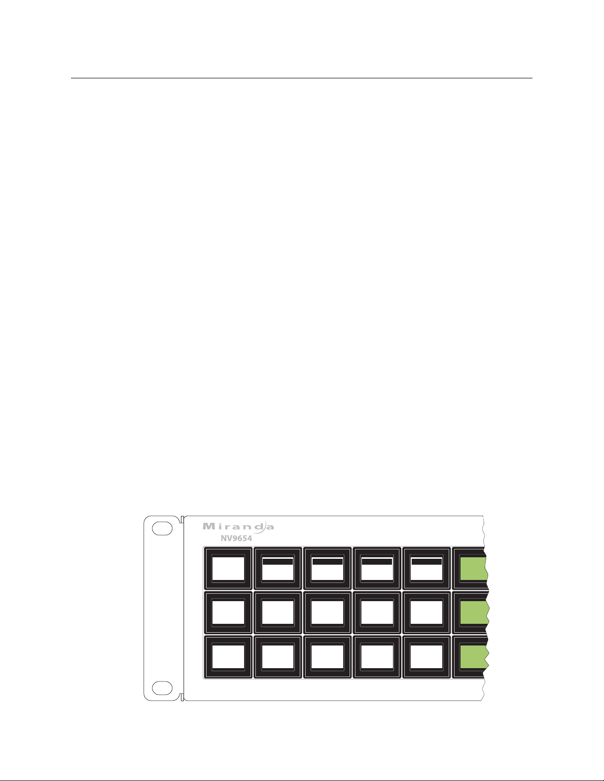
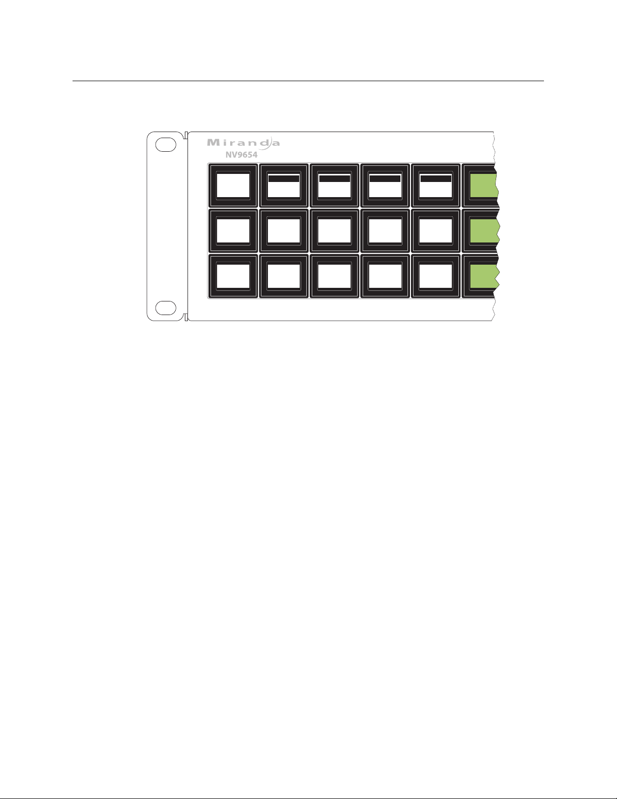
The NV96541 is a hierarchical control panel featuring 54 LCD function buttons (illuminated in
various colors and having 1 to 3 lines of text). The panel can be configured in either of two
behavioral modes:
• All-Button mode
• ‘Display and Button’ mode
Under ‘Display and Button’ mode, the left-most 15 buttons function as an alphanumeric display.
These buttons display the same information as some other panels that have displays, such as
the NV9640. Under this mode, the panel operator can turn the “display” on and off. When the
display is off, the 15 buttons can have other configured functions.
Under ‘All-Button’ mode, the panel provides no display. Note that under ‘Display and Button’
mode, the panel has 3 additional button functions that relate to the display.
The panel can operate in X-Y mode or in multi-destination (MD) mode. Operators can switch
between modes at any time.
This 2RU panel is organized as shown in figures 2-1 and 2-2:
. . . . . . . . . . . . . . . . . . . . . . . . . . . . . . . . . . . . . . . . . . . . . . . . . . . . . . . . . . . . . . . . . . . . . . . . 4
. . . . . . . . . . . . . . . . . . . . . . . . . . . . . . . . . . . . . . . . . . . . . . . . . . . . . . . . . . . . . . . . . . . . . . . 8
. . . . . . . . . . . . . . . . . . . . . . . . . . . . . . . . . . . . . . . . . . . . . . . . . . . . . . . . . . . . . . . . . . . 9
Fig. 2-1: NV9654 Front View
1. An equivalent NV9654V — a GUI that is called a “virtual panel”— is available. It emulates the NV9654.
3
Page 14
Introduction
GPIO (tally)
Ethernet
Serial (RS-232)
Power (2)
Panel Organization
At the rear, in addition to power, serial, and network connectors, is a 25-pin GPIO (i.e., tally)
connector that supports 4 optically isolated relay outputs and 8 optically isolated inputs:
Fig. 2-2: NV9654 Rear
The NV9654 is a compact unit, being 2RU and having an overall depth of 3.2”.
The NV9654 provides a tree-structured (or hierarchical) button layout. Configurers can define a
“tree” of button pages in such a way that each of the 54 LCD buttons can either (1) execute a
function or (2) select a subtree (i.e., present an entirely new set of functions at a different level in
the tree). The tree, with its subtrees, is not limited in size.
We use the term “button page” or “page” to mean the set of 54 button functions at any particular place in the tree. A panel that is configured in ‘Panel and Button’ mode shows the “display”
only on the top level page of the button “tree.”
Configurers will use ‘Navigate’ buttons to create new button pages (subtrees). During operation,
NV9654 users will press a ‘Navigate’ button to access a subtree. However, ‘Navigate’ buttons are
typically not labeled “Navigate”; they would be labeled according to the specific function they
perform in your system.
The panel can also display predefined button pages. For instance, a “category” button, when
pressed, can display one or more pages of sources or destinations through which the operator
may browse. A “menu” button presents a page of (pre-defined) menu options.
Panel Organization
Function Buttons
The NV9654 has an array of 54 LCD buttons. Each button has 1, 2, or 3 lines of text, 8 characters
per line. When there are one or two lines of text, the characters are large; when there are 3 lines
of text, the characters are smaller. (One or all of the lines of text might be blank). The buttons can
display one of seven colors dynamically: nominally red, green, blue, purple, amber, yellow, or
grey. We say a button is “dark” when its LCD is turned off.
During configuration, you can assign any of the 7 colors to a button.
Each LCD button has four levels of brightness: off, low, medium, and high, and supports three
operational levels: high tally, low tally, and off. High tally can be either medium or high brightness and low tally can be either low or medium brightness. High tally is always constrained to be
brighter than low tally. We say a button is “dark” when its LCD is turned off. See LCD Buttons
page 93, for a color chart.
Although you can see a list of the pages in the tree during configuration, the structure of the
tree is not evident on the panel itself. The panel operator must commit the tree structure to
4
,
Page 15
NV9654
X - Y
Dest
STATUS
VTR--4
VTR--4
LVL/DST
HD
SD
-S-I-L-
B
*
*
VTR--1 VTR--4
VTR--4
VTR--4
AUDIO 1
AUDIO 2
AUDIO 3
*
*
*
Page 1
VTR--4
VTR--4
VTR--4
AUDIO 4
AUDIO 5
AUDIO 6
*
*
*
PRESET
PAGE
UP
PAGE
DOWN
User’s Guide
memory to be able to use the panel. It is up to the person configuring the panel to design a
usable tree structure.
Some buttons functions are assigned by the system depending on the context. For example. if a
button page is to represent all sources in a category, and that list changes, the button subtree
adjusts in size dynamically. The panel software adds a “forward” button and a “back” button if
there are more sources than buttons. Pressing the ‘Forward’ button takes you to the next page
of sources. Pressing the ‘Back’ button takes you to the previous page of sources.
Some button states depend on context. Many buttons remain unlit when their functions are
disabled. For example, ‘Page Up’ and ‘Page Down’ buttons remain unlit until there is an opportunity to scroll up or down, respectively. By default, an XY/MD button turns green for X-Y mode
and amber for multi-destination mode.
The LCD buttons display a menu if the operator presses a menu button. When the operator
make a menu selection, the panel displays viewable data on the LCD buttons. In some cases, the
operator can enter data (such as panel ID or LCD brightness) using buttons that allow data entry.
Configurers can define ‘Selection’ buttons that select a level or an MD device. (They must do so if
the operator is to make such selections.)
Scrolling is necessary when a list of items
— for instance, levels or MD devices — exceeds the
number of buttons available for the items. Panels that use multi-destination mode will probably
require ‘Page Up’ and ‘Page Down’ buttons.
Alphanumeric Display
The panel can be configured in ‘All-Button’ mode or ‘Display and Button’ mode. In ‘Display and
Button’ mode, the left-most 15 buttons (a 5×3 array) form an alphanumeric display. (These
buttons therefore provide a 40×9 matrix of characters.) The panel operator has the option of
turning the display on or off. When the display is off, the 15 buttons can have other functions.
In ‘All-Button’ mode, the display is not present. In ‘Display and Button’ mode, the display is available only in the top-level button page.
The alphanumeric display provides real-time feedback for the operators as they make selections
to execute takes and other operations. The panel functions in two modes: X-Y or multi-destination. The display changes according to those modes. This is an example for X/Y mode:
5
Page 16
Introduction
MultiDes
STATUS
VTR--4
VTR--6
LVL/DST
VTR--1
VTR--2
-S-I-L-
B
*
*
VTR-12
VTR200
VTR--5
VTR--3
VTR--4
VTR--5
*
*
Page 1
VTR--6
VTR--7
VTR--8
VTR--6
VTR--7
VTR--8
PRESET
VTR--4
VTR--6
PAGE
UP
PAGE
DOWN
Panel Organization
Fig. 2-3: X/Y Mode
This is an example for multi-destination mode:
Fig. 2-4: Multi-Destination Mode
In either case, the display has 9 lines (1 header and 8 lines of information) and its buttons are
white. Operators might need to scroll the display to see additional information. (‘Page Up’ and
‘Page Down’ buttons can be used to scroll the display.
(It is with the ‘Toggle Display’ button that the operator hides or reveals the display.)
Display Fields
The display has 5 columns:
• Information (the left-most column, which has no heading).
The first entry in this column is either “X - Y” or ‘MultiDest” unless the panel is in salvo mode,
menu mode, or setup mode. See chapter 5 for those topics.
The bottom-most entry in this column is always the page number of the display, which can
scroll.
In X-Y mode, the second entry is always the word “Dest” as a title for the third entry which
identifies the destination currently selected. In Figure 2-3, the current destination is VTR--1.
In MD mode, there are no entries in this column other than the word “MultiDes” and the
page number.
• Preset.
The preset column indicates what source will be routed to a destination when the operator
presses the ‘Take’ button.
In X-Y mode, the preset column represents the levels of a source or the levels of multiple
sources under breakaway. These are called the preset source(s). After the take, they disappear
from the preset column and re-appear in the status column, reflecting that the preset
sources have now become current sources.
In MD mode, the preset column indicates the sources that will be routed to selected destinations in the ‘Level/Dest’ column. These are the preset source(s). After the take, they disappear
6
Page 17

NV9654
User’s Guide
from the preset column and re-appear in the status column, reflecting that the preset
sources have now become current sources.
• Status.
The status column indicates what source(s) have been routed to the currently selected destination.
In X-Y mode, the status column represents the levels of a source or the levels of multiple
sources under breakaway. These are called the current source(s).
In MD mode, the status column represents the sources routed to each of the destinations in
the ‘Level/Dest’ column. Again, these are the current sources.
• LVL /DST.
(This stands for “level/destination.”)
In X/Y mode, this column identifies the levels of the currently selected destination. That destination is identified in first column, the information column. In Figure 2-3, ‘VTR 1’ is selected.
Operators might need to scroll to see or select a level.
In MD mode, the ‘Level/Dest’ column presents all the MD devices (destinations) defined in
the NV9654 configuration. (Actual destinations are defined in the NV9000 system configuration.) Operators might need to scroll to see or select a destination.
• S-I-L-B (Attributes).
This column represents 4 attributes of the levels or destinations present in the ‘LVL/DST’ column:
“S” stands for selected. An asterisk (*) in the “S” column means that the associated level (or
destination) is selected. A blank space in the “S” column means that the level (or destination)
is not selected.
In X-Y mode, an “*” indicates that a level is selected. In MD mode, an “*” indicates that an
MD device is selected.
“I” stands for information. An asterisk in the “I” column means that the additional information
regarding the associated level or destination is available. Press an ‘Information’ button to
view the information.
“L” is the heading for locks and protects. An “L” in the “L” column means that the associated
level (or destination) is locked. A “P” in the “L” column means that the associated level (or
destination) is protected. A blank space in the “L” column means that the level (or destination) is neither locked nor protected.
NV9654 operators may lock, protect or release destinations. It is important for operators
to know that other operators may lock, protect, or release sources and destinations.
When we say a level is locked (or protected), we really mean that the currently selected
detination is locked on that level.
“B” stands for breakaway. In X/Y mode, an asterisk in the “B” column means that the associated level is a breakaway level. A blank space in the “B” column means that the level is not a
breakaway level. In MD mode, an asterisk indicates a breakaway on the associated destination.
The display fields can show either names from a name set or system mnemonics for devices
depending on (1) the state of the ‘Name Set Toggle’ button (if the panel has one), (2) the default
name set (3) the existence of name sets in the NV9000 configuration. (An “alias” is a name
defined in a name set.) See Panel Options
on page 21.
7
Page 18

Introduction
Modes of Operation
Tally Interface
At the rear of the panel is a DB25 connector that provides 8 tally inputs and 4 tally outputs. (The
outputs are solid state relay outputs.) Both inputs and outputs are optically isolated.
During configuration, you can construct expressions of Boolean logic that switch the outputs on
or off. The terms of the logic expressions are states of the source and destination devices, etc.,
controlled by the NV9000 control system.
During configuration, you can define NV9654 behavior that will follow the tally inputs.
What you connect to the tally interface is, of course, up to you. Grass Valley provides a breakout
cable (WC0053) for the tally connector
The NV9000-SE Utilities on-line help calls the tally interface a GPIO interface. On the rear of the
panel, it is labelled a “GPI interface.”
See chapter 6, GPIO
Modes of Operation
The panel operates in either X-Y mode or multi-destination (MD) mode. The panel has a button
type (XY/MD) that toggles between the modes. A third mode
destination,” or “button-per-source” mode
The primary modes of operation are:
• X-Y mode — control of individual router levels. Choose a destination, optionally choose
desired breakaway levels, choosing source(s), and press ‘Take’ to complete a desired route.
• Multi-destination mode — lets you control multiple destinations. The LCD buttons display
destinations and sources. You can scroll through destination lists using the ‘Page Up’ and
‘Page Down’ buttons. Select a destination using selection buttons, choose a source, and
repeat for all desired routes. Then press ‘Take’. Takes in MD mode are “all level,” and breakaways cannot be performed.
A ‘Hold’ button allows you to select many MD destinations at once.
• Single-destination mode.
Single-destination” mode is not a distinct mode, but we mention it here because it is a mode
on some other panels and can be simulated on the NV9654. It can be combined with the
other two modes. You can create many different forms of “single-destination” mode.
To understand single-destination mode, you must understand the different button types.
Please read the Configuration and Operation chapters and then see Single-Destination
Mode (page 41).
The secondary modes of panel operation are:
• Setup mode — where the NV9654 is freshly powered up, but disconnected from the net-
work. In this mode, you can preset the NV9654’s panel ID and perform a few diagnostic tasks.
• Salvo mode — pressing a Salvo button (and then the ‘Take’ button) executes a salvo. (The
duration of a salvo is indeterminate.)
• Menu mode — pressing a Menu button places the NV9654 in “menu” mode. In menu mode,
the panel’s button array becomes a menu that changes as needed during menu operation.
— as a purchase option.
, on page 81, for complete detail.
— called “single-bus,” “single-
— can be emulated in either X-Y mode or MD mode.
8
Page 19

Other modes of operation are:
• Hold mode — when you press the ‘Hold’ button, hold mode becomes active and when you
press it again, hold mode becomes inactive. See Hold
• Save preset mode — when you press the ‘Save Preset’ button, ‘Save Preset’ mode becomes
active and when you press it again, ‘Save Preset’ mode becomes inactive. See Save Preset
page 62.
Other NV9654 Functions
The NV9654 can be configured to perform the following additional functions:
• Previous source, free source, “quick” source, and immediate source/destination selection.
• Return to a pre-defined (or default) state.
• Hold breakaway levels.
• System salvos.
• Lock/protect/release for destinations.
• Forced release of locked or protected devices.
• Device selection using indexes or suffixes.
NV9654
User’s Guide
on page 59.
on
The NV9654 provides the following additional features:
• The NV9654 supports multiple-level breakaways in X-Y mode. This lets you route multiple
sources to the same destination on different levels.
• The panel supports gang or dub switching in multi-destination mode.
• Broadcast data routing in X-Y mode.
• Level mapping.
• Button page “templates”— global navigation templates and suffix templates — for easier
configuration.
9
Page 20

Introduction
Other NV9654 Functions
10
Page 21

Chapter 3 provides installation and connection instructions.
Topics
Package Contents . . . . . . . . . . . . . . . . . . . . . . . . . . . . . . . . . . . . . . . . . . . . . . . . . . . . . . . . . . . . . . . . . . . . . . . . 11
Installation . . . . . . . . . . . . . . . . . . . . . . . . . . . . . . . . . . . . . . . . . . . . . . . . . . . . . . . . . . . . . . . . . . . . . . . . . . . . . . . 12
Installing Software and Documentation . . . . . . . . . . . . . . . . . . . . . . . . . . . . . . . . . . . . . . . . . . . . . . . . . . 12
Initialization . . . . . . . . . . . . . . . . . . . . . . . . . . . . . . . . . . . . . . . . . . . . . . . . . . . . . . . . . . . . . . . . . . . . . . . . . . . . . . 13
Tes ti ng . . . . . . . . . . . . . . . . . . . . . . . . . . . . . . . . . . . . . . . . . . . . . . . . . . . . . . . . . . . . . . . . . . . . . . . . . . . . . . . . . . . 14
Package Contents
If you have ordered one or more NV9654 control panels from Grass Valley, inspect the shipping
container for damage. If you find any container damage, unpack and inspect the contents. If the
contents are damaged, notify the carrier immediately.
As you unpack the shipping container, look for the packing slip and compare it against the
contents to verify that you received everything as ordered. If anything is missing (or if you find
equipment damage unrelated to shipping), please contact technical support. Refer to Grass
Valley Technical Support on page 107.
Depending on your order, the NV9654 items that can ship include:
• One or more NV9654 control panels.
• One or two power supplies for each NV9654, with straps that secure the AC power cords to
the power supplies.
• Optional WC0053 breakout cable.
The package does not contain network cables, serial cables, or mounting screws.
You do not need to take any special precautions regarding ESD.
This document does not address the shipment or installation of any other equipment or software that can be used in conjunction with the NV9654 (including the NV9000 system controller,
NV915 system controller, NV915 system controller, other NV96xx control panels, EC9700 GUI,
EC9710 GUI, and configuration programs such as UniConfig, MRC, or NV9000-SE Utilities).
This document does briefly address the use of NV9000-SE Utilities and the Panel IP Configuration Utility as they pertain to panel configuration.
Installation
11
Page 22

Installation
2
1
4
3
Receptacle
n.c.
n.c.
GND
12VDC
4
3
21GND
12 VDC
n.c.
n.c.
Plug
Installation
Installation
Follow these steps to install a NV9654 control panel:
1 Mount, and secure, the panel in the rack.
The NV9654 is designed to mount in a 19” rack. Rack-mounting is not a requirement.
Place the panel in position in your rack. Attach the panel to the rack frame, using screws
appropriate for your rack. The panel’s mounting slots are spaced 3.00” (76.2mm) vertically
and allow approximately 1/8” (3mm) of movement horizontally.
2 We assume that you have an Ethernet switch connected to the “Panel and Router Network”
port of your system controller. Connect an Ethernet cable from that switch to the RJ-45 port
at the rear of the NV9654.
3 Connect one or both power supplies. First connect the 4-pin connector to PS1 or PS2 on the
rear of the router. The connectors are keyed and snap into place. There is only one way they
fit. Do not force them. Then connect the power supply to AC power.
A second power connection is for redundancy only (protection against failure) and is not a
requirement for operation.
Refer to Power Specifications
Power Cord Retention
on page 87 for details on the PS0001 power supply. See also
on page 93.
4 Connect tally (GPIO) input devices and output devices at the DB25 GPI connector.
You can use the optional WC0053 breakout cable to make these connections.
See chapter 6, GPIO, on page 81 for detail regarding the tally interface.
Installing Software and Documentation
This document is available through the Grass Valley web site.
You must use NV9000-SE Utilities to configure the NV9654 control panel. Contact Grass Valley if
you need to obtain the latest version of this NV9000 configuration software.
You may use the Panel IP Configuration Utility if you want to your NV9654 to have a static IP
address or to use DHCP. The panel, as it comes from the factory, defaults to DHCP.
12
Page 23
Initialization
NV9654
PANEL ID
65410
NO
SERVER
MENU
• • •
ENTER
PANEL ID
SOFTWARE
VERSIONS
EXIT
• • •
PANEL
TEST
MODE
0 0 CLEAR CLEAR
SAVE SAVE
EXIT EXIT
1 1 2 2 3 3 4 4 5 5 6 6 7 7 8 8 9 9
PANEL IDPANEL ID
65410 65410
PANEL IDPANEL ID
1234 1234
Before your NV9000 system controller can communicate with an NV9654, you must give it a
panel ID. Follow these steps for each NV9654 you are installing:
1 Power up the NV9654. Do not connect its Ethernet cable. (Disconnect it if it is connected.)
2 Press the ‘Menu’ button to enter the menu. The menu button now displays ‘Exit’. At any time
3 Find and press ‘Enter Panel ID’ among the panel buttons on the left.
NV9654
User’s Guide
After a few seconds, the alphanumeric display will show ‘No Server’ at the top and show the
panel’s current panel ID. The 2 left-most buttons and the right-most button in the top row
now read:
during this process, you can press the exit button to “back out of” the process. You might
have to press it more than once.
4 After you press ‘Enter Panel ID’, the panel illuminates 10 “digit” buttons at the left end of the
top row of buttons. Press the digits of your intended panel ID
— up to 8 digits. The digits you
enter appear on the button next to the ‘Clear’ button at the right. If you make an error, press
the ‘Clear’ button to start over.
5 Then press the ‘Save’ button (on the right) to save the ID, or press the ‘Clear’ button to dis-
card the ID.
The new panel ID does not appear until you exit the menu after saving.
6 You may use any other menu function at this time. When you are finished, press the ‘Exit’
button (which reappears) to leave the menu.
7 After you designate the panel ID, reconnect the Ethernet cable. The system controller will
detect your panel in a few seconds. (All panel IDs must be unique.)
You can now prepare an NV9654 configuration in NV9000-SE Utilities and upload the configuration to the NV9654. You need the panel ID to create a NV9654 configuration. When you upload
the configuration, the panel ID you entered in NV9000-SE Utilities designates the actual panel to
which the upload will occur. The panel might be a physical panel or a virtual panel. If no actual
panel has that ID, the upload cannot occur.
13
Page 24

Installation
Testing
Testing
As shown above in step 3, a panel test function is available when the NV9654 is disconnected
from the system controller. The test determine the “health” of the buttons of your NV9654. See
Setup Mode
installed software and firmware.
These are points to consider after you install your NV9654 control panel(s):
1 Do the buttons illuminate? When an NV9654 powers up, its two leftmost LCD buttons are
supposed to turn green. Does it pass the panel test mentioned above?
2 When the NV9654 powers up and it is connected to the system controller, it should initialize
completely. (That takes a few seconds.) The NV9000 system should load whatever configuration exists for that panel and the buttons appropriate for that configuration should light in
the colors appropriate for the top-level button page of that configuration.
If you continue to see “No Server,” “Acquiring IP Address,” or “Locating Network” on button 2,
you have a problem. Reboot everything and try again.
The NV9654, by default, acquires its IP address through DHCP on the NV9000’s panel/
If (in setup mode) you do not see your designated panel ID on the top left button, you have
either not initialized the panel or no configuration has been created for your panel in
NV9000-SE Utilities.
3 Is the system controller actually running? With the typical noise levels in a facility, it can
sometimes be difficult to tell. Use the ‘System’ pages of NV9000-SE Utilities to make the
determination.
4 Is NV9000-SE Utilities installed and operating? If so, can you upload a configuration to the
specified panel?
5 Does the configuration actually work? Is it useful? Can the operator perform takes and per-
form other operations?
The design of an NV9654 “operator interface” is non-trivial. You might want to consider how well
your operator interface works in addition to the basic question of whether it works.
on page 78 for detail. Press the ‘Software Versions’ button to review the versions of
router network. You can use the Panel IP Configuration Utility to force the panel to have a
static IP address.
14
Page 25

Configuration
Chapter 4 provides configuration instructions for the NV9654.
Topics
Summary . . . . . . . . . . . . . . . . . . . . . . . . . . . . . . . . . . . . . . . . . . . . . . . . . . . . . . . . . . . . . . . . . . . . . . . . . . . . . . . . 15
Adding a Panel to an NV9000 Configuration
NV9654 Panel Configuration Page
Commitment Buttons
Panel Options
Button Definitions
Button Page List
Tally (GPIO) Window
Selection Buttons
Single-Destination Mode
Multi-Destination Configuration
Global Navigation
Persons not interested in NV9654 configuration need not read this chapter.
. . . . . . . . . . . . . . . . . . . . . . . . . . . . . . . . . . . . . . . . . . . . . . . . . . . . . . . . . . . . . . . . . . . . . . . . . . . . 21
. . . . . . . . . . . . . . . . . . . . . . . . . . . . . . . . . . . . . . . . . . . . . . . . . . . . . . . . . . . . . . . . . . . . 21
. . . . . . . . . . . . . . . . . . . . . . . . . . . . . . . . . . . . . . . . . . . . . . . . . . . . . . . . . . . . . . . . . . . . . . . . 25
. . . . . . . . . . . . . . . . . . . . . . . . . . . . . . . . . . . . . . . . . . . . . . . . . . . . . . . . . . . . . . . . . . . . . . . . . . 37
. . . . . . . . . . . . . . . . . . . . . . . . . . . . . . . . . . . . . . . . . . . . . . . . . . . . . . . . . . . . . . . . . . . . . . 38
. . . . . . . . . . . . . . . . . . . . . . . . . . . . . . . . . . . . . . . . . . . . . . . . . . . . . . . . . . . . . . . . . . . . . . . . . 38
. . . . . . . . . . . . . . . . . . . . . . . . . . . . . . . . . . . . . . . . . . . . . . . . . . . . . . . . . . . . . . . . . 41
. . . . . . . . . . . . . . . . . . . . . . . . . . . . . . . . . . . . . . . . . . . . . . . . . . . . . . . . . . . . . . . . . . . . . . . . 44
. . . . . . . . . . . . . . . . . . . . . . . . . . . . . . . . . . . . . . . . . . . . . . . . . . . . . . . . 18
. . . . . . . . . . . . . . . . . . . . . . . . . . . . . . . . . . . . . . . . . . . . . . . . . . . . . . . . . . 42
. . . . . . . . . . . . . . . . . . . . . . . . . . . . . . . . . . . . . . . . . . . . . . 15
Summary
The NV9654 has a “multi-page” user interface. Each of its 54 buttons (illuminated in various
colors and having 3 lines of text) can either (1) execute a function or (2) select another button
page (i.e., present another set of functions). The number of different button pages is not limited.
Panel operators navigate to different button pages to perform different tasks.
We say that the user interface is tree-structured (or hierarchical) although it is not always a “tree”
in the strictest sense. (It is possible to construct a tree-like graph of the button pages.)
Fifteen of the NV9654’s buttons — a 5×3 button array at the left of the panel — can optionally
be configured as an alphanumeric display that presents the status of operations as they occur.
An NV9654 configuration typically provides ‘Page Up’ button and ‘Page Down’ buttons with
which the operator can scroll the display. The operator can turn the display on and off.
At the rear of the panel, a DB25 connector supports 8 tally inputs and 4 tally outputs.
NV9000-SE Utilities is the software with which to configure the NV9654. Figure 4-1, following,
shows the default NV9654 panel configuration page from NV9000-SE Utilities.
Adding a Panel to an NV9000 Configuration
You must create configurations for the NV9654 using NV9000-SE Utilities. We assume that you
are familiar enough with NV9000-SE Utilities that you can understand the following material. It
is not difficult material, but some of the concepts might not be familiar to everyone.
It takes only a few seconds to add a new panel configuration.
15
Page 26
Configuration
Adding a Panel to an NV9000 Configuration
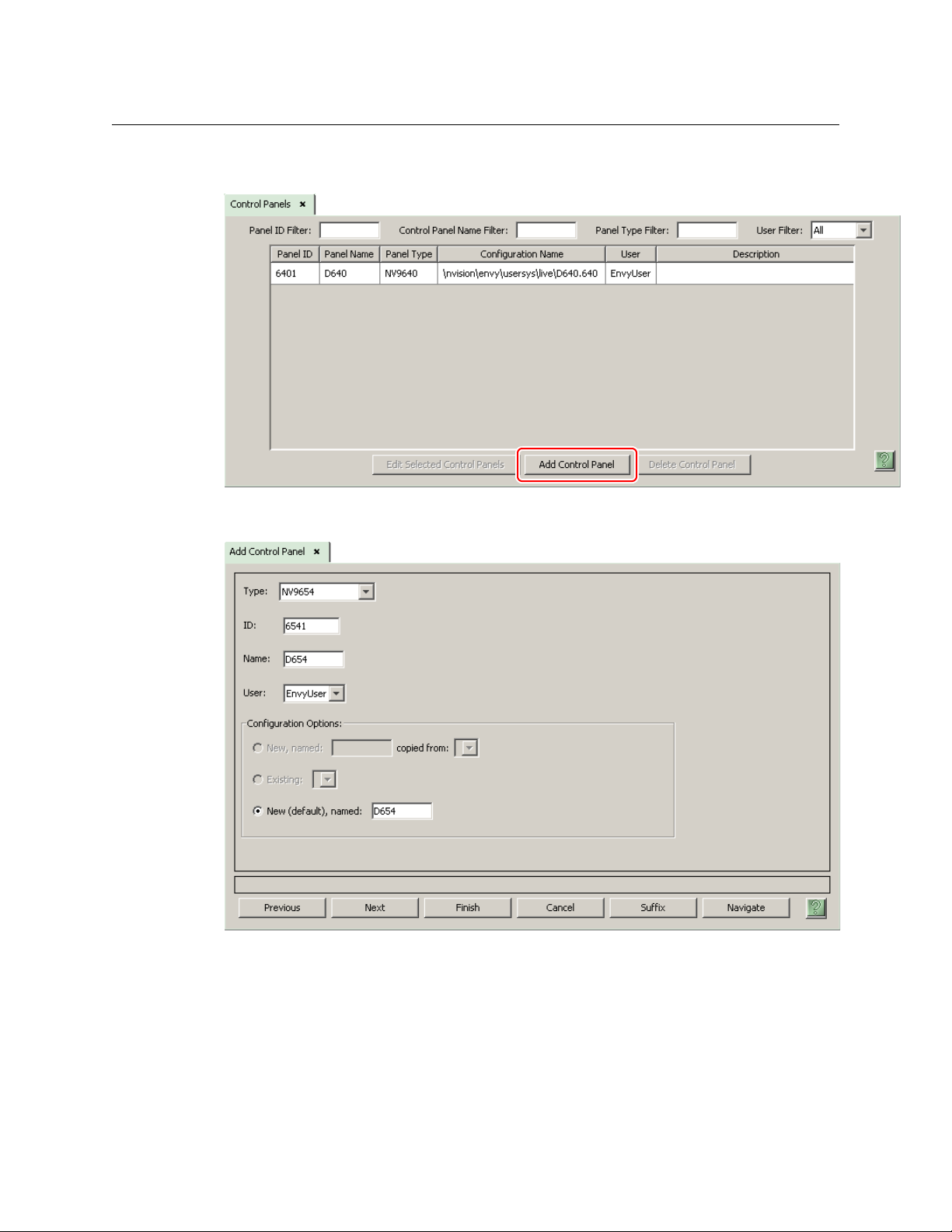
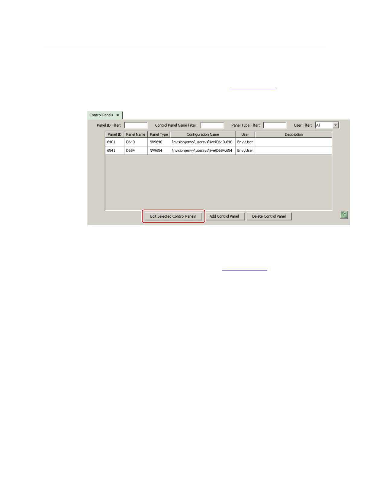
After launching NV9000-SE Utilities, choose ‘Control Panels’ from the Configuration pane in the
navigation area. The ‘Control Panels’ configuration page appears:
Click ‘Add Control Panel’ at the bottom of the configuration page. The ‘Add Control Panel’ page
appears:
16
Choose “NV9654” from the ‘Type’ field. In the ID field, enter the panel ID you assigned to the
panel while it was in setup mode. Give a name to the panel in the name field and select a user.
When you are creating a panel configuration you have 3 options. These options are presented in
the ‘Configuration Options’ area:
1 Make a copy of an existing configuration file, giving it a new file name.
2 Use an existing configuration file. (This allows several panels to share a single configuration.)
3 Create an entirely new configuration file.
Page 27
NV9654
User’s Guide
In the first and third cases, you will create a new configuration file whose name you designate.
The file extension for an NV9654 configuration file is
There are 2 other buttons: ‘Suffix’ and ‘Navigate’. Pressing either of these buttons creates a
button page template, not a panel configuration. See Global Navigation
.654. Click ‘Next’ or ‘Finish’ to proceed.
on page 44.
Return to the ‘Control Panels’ page to view your new entry. To edit an NV9654 configuration,
either double-click its list entry or select the entry and then click ‘Edit Selected Control Panels’:
You will then see the panel configuration page for the selected NV9654.
The following section of this guide discusses using the panel configuration page in which you
configure an NV9654.
The entries in the control panel list can be (1) actual panel configurations (2) global naviga-
tion templates or (3) global “suffix” templates. See Global Navigation
on page 44.
17
Page 28
Configuration
Button
Definition
Section
Button
Page Table
GPIO Defi-
nitions
Panel
Options
Panel Image
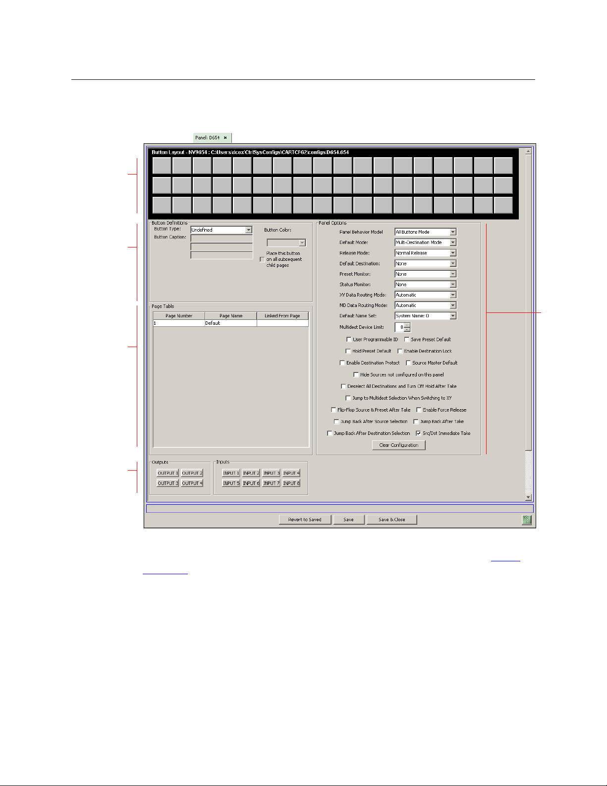
NV9654 Panel Configuration Page
NV9654 Panel Configuration Page
This is the default NV9654 panel configuration page in NV9000-SE Utilities:
Fig. 4-1: NV9654 Configuration Page (Default, All Buttons Mode)
Similar pages exist for NV9654 suffix templates and global navigation templates. See Global
Navigation on page 44.
Figure 4-1 shows the default panel configuration page, which has no buttons defined. After you
configure buttons, and button pages, the appearance of the panel buttons will have changed.
At the bottom of the page are two important configuration buttons: ‘Revert to Saved’ and ‘Save’.
The ‘Save’ button commits modifications you have just made. The ‘Revert to Saved’ button
restores the last saved version of the panel configuration, canceling any changes you just made.
The ‘Save and Close’ button, also at the bottom, dismisses the configuration page in addition to
saving the configuration changes.
18
Page 29
NV9654
User’s Guide
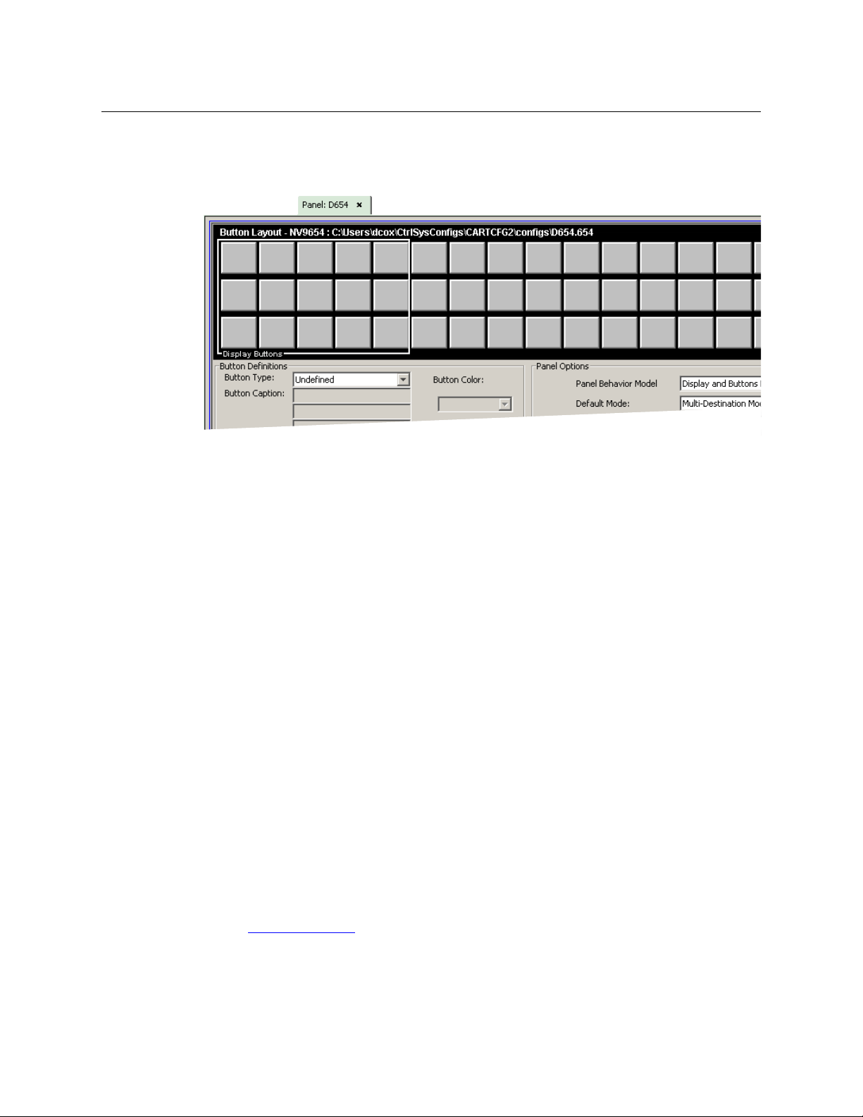
The previous ilustration showed the configuration page set up for ‘All Buttons’ mode. The panel
can also be configured in ‘Display and Buttons’ mode, in which case the “display” section of the
button matrix is delineated by a white line on the page:
Fig. 4-2: NV9654 Configuration Page (Default, ‘Display and Buttons’ Mode)
The display section is the 5×3 array of buttons at the left.
Regions of the Configuration Page
T here are 5 main regions:
• The NV9654 panel image.
The NV9654 has 54 LCD buttons in an 18×3 array. Click on a button to assign a function to it.
In some cases, you can click or double-click a button to execute the button function. Double-clicking a ‘Navigate’ button, for instance, causes the button’s “subpage” to appear.
Buttons can be illuminated in several colors: green, amber, yellow, red, blue, purple, and
grey. There are 3 levels of illumination: high tally (bright), low tally (muted) and off. Undefined buttons are turned off (dark) on the actual panel and are gray in the configuration
page.
Buttons in the 5×3 display section are always white (if the display is enabled). Operators can
turn the display on and off. Configurers may assign button functions to the buttons of the
display section for those occasions when the operator has turned the display off.
The display is available only at the top-level page of the button tree.
Buttons disabled during operation have text, but are dark on the control panel. Unde-
fined buttons are dark and have no text.
• Button definition section.
In this section, configurers make button assignments, using its pull-down menus and text
fields. It is here that the button captions are defined and the button color is specified. (For
some button types, you cannot define a caption. The button text is defined by the system.)
See Button Definitions
, following.
19
Page 30

Configuration
NV9654 Panel Configuration Page
• Button page table.
This section
ual pages of the tree structure. The button page at the top of the list (or root of the tree) is
called “Default.”
During operation, category buttons can display device subpages when pressed. Those subpages are not explicitly definable in NV9000-SE Utilities. The button page list does not display the device subpages accessed through category buttons. Category buttons can also
display suffix pages when pressed. Suffix pages are included in the button page table.
See Button Page List
• GPIO definitions.
In this section, configurers may define GPIO logic. The control panel has a rear connector
that provides 4 relay outputs and 8 optically isolated inputs. See GPIO
information. (Note that the graphical buttons represent connector terminals and not actual
buttons.)
• Panel options.
In this section, configurers may specify the behavioral characteristics of the panel.
See Panel Options
— the region below the button definition section — displays a list of the individ-
on page 37.
, page 81, for more
on page 21.
Configuration Tasks
The person configuring an NV9654 panel will want to consider how best to use the hierarchical
nature of the button tree to support the devices and routers in the router control system at
hand. The task is non-trivial.
In support of that effort, the configurer will do the following:
• Select panel options.
• Assign functions to buttons.
• Create pages (subtrees) of buttons. (Do this using the Navigation button type).
• Define logic for some or all of the tally inputs and outputs.
A configuration should lead the operator through required tasks. It is possible to make navigation through the tree structure of panel operations intuitive through the judicious use of color
and text on the LCD buttons.
The configurer must keep in mind that the operator generally cannot view the entire button
tree at a glance.
The configurer must also keep in mind that the operator must be able to reach any page in the
tree. In particular, the operator, having navigated down a subtree, must have some way to navigate back up the subtree. There are several ways to ensure this. Two are listed here:
• Place a “Back” button on each subpage. The “back” button causes the NV9654 to redisplay
the previous page.
• Place a “Navigate” button on each page, where the navigate button causes the NV9654 to
display a specific page.
The operator can always return from system-generated pages (e.g., device lists) using the
‘back’ button.
20
Page 31

The panel operator, in most cases, needs a ‘Take’ button and at least one selection button. In
addition to their basic function, selection buttons provide feedback about the preset source
device and level mapping. A ‘Clear Preset’ button is strongly recommended.
Commitment Buttons
Two buttons at the bottom of the configuration page are self-explanatory and present on most
configuration pages:
• Revert to Saved. Press this button if you want to discard any recent changes you have made.
• Save. Press this button to commit all your recent changes.
Neither of these actions is reversible.
The ‘Save and Close’ button, also at the bottom, dismisses the configuration page in addition to
saving the configuration changes.
Panel Options
The panel options section, at the right of the configuration page, has two parts: drop-down
menus and checkbox options. These are the drop-down menus:
NV9654
User’s Guide
These are its drop-down menu options:
Behavioral Model All Buttons mode The panel does not include a simulated alphanumeric display. See
Defaults
Display and Buttons mode
Default Mode X-Y Mode Starts the panel in XY mode after a reset. See Defaults
Multi-Dest Mode Starts the panel in multi-destination mode after a reset.
Release Mode Normal Release This panel can release “locks” and “protects” set by the designated
Force Release This panel can release locks and protects set by any user.
The panel does include a simulated alphanumeric display. It is possible for the operator to turn the display on and off.
user (at this panel or any other panel).
on page 89.
on page 89.
21
Page 32

Configuration
Panel Options
Default
Destination
Preset Monitor None The preset source video is not sent to a monitor.
Status Monitor None The current source video is not sent to a monitor.
XY Data
Routing Mode
None After a reset, the panel displays no destination device. (This is not
recommended.)
‹device› The Panel uses the specified device as the destination after a reset.
(The ‘Default State’ button also returns the panel to this destination.)
‹device› The preset source video for the selected destination appears on
the specified monitor (device).
‹device› The current source video for the selected destination appears on
the specified monitor (device).
Automatic If a machine control (i.e., data) level is involved in a route, the sys-
tem makes the route on the control level even if the control port is
in use on the source or destination device. It breaks the previous
control connection and then makes a new control connection for
the route in progress.
Semi-automatic
(recommended)
Manual If the control port is in use for the source or destination device, the
If the control port is in use for the source or destination device, the
system takes all (selected) levels except control and allows the
operator to perform the control level route by pressing ‘Take’ a second time. The operator may cancel the control-level take by pressing a button other than ‘Take.’
If the control port is not in use, the control level take occurs normally.
system takes all (selected) levels except control. It does not perform the control level route.
If the control port is not in use, the control level take occurs normally.
To carry out a take on a machine control port that is in use, the
operator must first free the port by performing a “tristate” take on
the port, that is, taking the device (as a source) to itself (as a destination) on the control level.
A take can occur on the machine control level if, in the status column of the display, the source entry is “FREE.”
22
Page 33

NV9654
User’s Guide
MD Data
Routing Mode
Default Name
Set
Multidest
Device Limit
Automatic If a machine control (i.e., data) level is involved in a route, the sys-
tem makes the route on the control level even if the control port is
in use on the source or destination device. It breaks the previous
control connection and then makes a new control connection for
the route in progress.
Manual If the control port is in use for the source or destination device, the
system takes all (selected) levels except control. It does not perform the control level route.
If the control port is not in use, the control level take occurs normally.
To carry out a take on a machine control port that is in use, the
operator must first free the port by performing a “tristate” take on
the port, that is, taking the device (as a source) to itself (as a destination) on the control level.
An operator can determine whether the control level is free by
switching momentarily to X-Y mode and examining the destination’s levels.
System Name A list of “name sets” appears in the drop-down menu. The name
sets can be defined under the System Management pane of
NV9000-SE Utilities. Choose ‘System Name’ in this list if you do not
want, or do not care about, device name aliases.
Do not choose ‘System Name’ if you are configuring any ‘Name Set
Toggle’ buttons.
(Selectable in
multiples of 8)
The number of multi-destination entries you are allowing. Make
this value equal to or greater than the number of MD devices you
need. The default, and lowest value, is 8. The maximum is 512.
(Elsewhere in the configuration, you will create a list of MD devices.
You can leave some MD destinations unassigned.)
Checkbox Options
The checkbox options section is at the bottom of the panel options section:
A check in the box enables the option. Clearing the checkbox disables the option.
23
Page 34

Configuration
Panel Options
By default, all the check box options are unchecked except ‘Src/Dst Immediate Take’. That particular option is enabled by default.
The ‘Clear Configuration’ button removes all configuration data from the panel. The panel then
has a blank configuration. If you click this button by mistake, you can regain the previously
saved configuration by clicking the ‘Revert to Saved’ button.
The check box options differ under the ‘All Buttons’ model and the ‘Display and Buttons’ model.
The difference is the ‘Page VFD Only’ option which is available only under the ‘Display and
Buttons’ model.
The following items are the checkbox options:
• User-Programmable ID.
Allows the Panel ID to be changed locally at the control panel (in menu mode).
• Save Preset Default.
Makes ‘Save Preset’ mode active when the panel reverts to its default state (after a Default
State button is pressed, or when the panel is restarted).
A ‘Save Preset’ button is needed only when you want the operator to be able to view or
change the mode.
• Hold Preset Default.
Makes “hold” mode active when the panel reverts to its default state (after a Default State
button is pressed, or when the panel is restarted).
Note: a ‘Hold’ button is needed only when you want the operator to be able to view or
change the mode.
• Enable Destination Lock.
Check ‘Enable Destination Lock’ so that any ‘Destination Lock’ button on the panel will function.
• Enable Destination Protect.
Check ‘Enable Destination Protect’ so that any ‘Destination Protect’ button on the panel will
function.
• Source Master Default.
Makes a control-level source the controlling device (or master device) by default. Otherwise,
the destination is the master by default. (The option is specifically for use with NV9000 series
machine control routers.)
“Source is master” is used for duplication, or broadcast routing, on a machine control level.
“Destination is master” is for machine-to-machine editing. If you do not select the “source
master default” option, you can place a ‘Source is Master’ button on the panel.
Note: a ‘Source is Master’ button is a toggle that reverses the direction of data routing
for devices used in data level (machine control) takes.
• Hide sources not configured on this panel.
Causes the names of source devices that are not presently configured for this particular
panel to be effectively hidden. When another panel changes the source to one not configured for this panel, this panel displays asterisks instead.
• Deselect all destinations and turn off hold after take.
24
Page 35

NV9654
User’s Guide
After selecting many MD destinations (with ‘Hold’ mode on), it can be time-consuming and
error-prone to find them all (and no others) to deselect them after a take. When you enable
this option, the NV9654 does exactly that (and turns off hold mode).
• Jump to multi-dest selection when switching to XY.
Makes the currently selected multi-destination device the current destination when you
switch from MD mode to X-Y mode.
The X-Y destination shown will be the default destination when the panel is in MD “hold”
mode and multiple destinations are selected
configuration. Otherwise, no destination will be selected.
— if a default destination is specified in the
• Flip-flop source and preset after take.
Swaps the preset source and the currently routed source for this destination after a take.
• Enable force release.
Allows operators to execute a force release.
• Jump back after source selection.
After you make a source selection, the panel reactivates the default button page.
• Jump back after take.
After you press a ‘Take’ button, the panel reactivates the default button page.
• Jump back after destination selection.
After you make a destination selection, the panel reactivates the default button page.
Jumping back to the default page is usually helpful, but in some configuration designs,
might not be. You can design your panel configuration to take advantage of the jumpback behavior.
• Src/dst immediate take.
A ‘Src/Dst’ button connects a source to a destination. When this box is checked (as it is in the
default NV9654 configuration) the button performs an immediate take. When the box is
clear, the button sets up the preset and the operator must press a ‘Take’ button to complete
the take.
• Page VFD only.
The panel pages the display (here called a VFD) only and does not page selection buttons.
(See Selection Buttons
This option is available only when the panel is being configured under the ‘Display and Buttons’ model.
Further, the option is meaningful (or useful) only when the panel has no ‘VFD/Sel Paging
Toggle’ button (anywhere in any of its button pages).
on page 38.)
Button Definitions
There are four classes of button functions:
• Dedicated functions, such as ‘Default State’ or ‘Chop’.
• Variable functions, such as ‘Category’ or ‘Source’. With this type of button, additional selec-
tions are needed to complete the button configuration.
25
Page 36

Configuration
Button Definitions
• Special functions, such as ‘Navigate’ and ‘Back’. These functions allow the panel operator to
move from one button page to another. (The Navigate button is unique: it initiates a dialog
in which you create a subtree.)
• System-generated button functions. These are buttons that are generated dynamically (by
the router control system) during operation. An example of system-generated buttons is a
device list generated when the user presses a category button. The set of devices in a category can change over time (as the configuration database changes); the NV9654 device list
changes also.
The number and names of categories can also change over time and the NV9654 will track
those changes too.
Note
Certain button fields contain a colon (:) and number after the data in the field. The
number is the record ID of the object in the NV9000 configuration database. The
record IDs can be ignored but might be of some use when the configurer is searching
for items in the configuration database.
There are different sets of button types for global suffix pages and for global navigation pages.
See Global Navigation
on page 44.
Button Specification
The button definitions section has several controls:
The controls vary according to the button type.
Button Type A pull-down menu where you may select a button type.
Button Caption Three text boxes in which you can enter three lines of button text up to 8
characters each. SE provides a default for the button caption.
Some buttons do not allow you to enter button text. Category buttons, for
example, use the category name as the button text.
26
Page 37

NV9654
User’s Guide
Button Color A pull-down menu where you can select a button color: amber, blue, green,
grey, purple, red, or yellow:
On the panel, each of the 7 defined colors has two brightness levels: “hightally” and “low-tally.” Buttons are dark if their functions are disabled.
Buttons are low tally if they are available and unselected. Buttons are high
tally when they are selected. (An exception to this is the LCD brightness
submenu when the panel is in menu mode.) Some button types are never
high-tally.
Check box “Place this button on all child pages.” When the operator presses a naviga-
tion button, its target page appears on the buttons. Any page can have
multiple navigation buttons and therefore multiple target pages. If you
check this option, the button you are defining will occur, in the same posi-
tion, on all pages in the subtree available through the navigation button.
A “back” button is a good candidate for such a button. The back button
returns the operator to the previous page. (Back buttons are automatically
placed on list pages and most navigation target pages.)
Check box “Use custom button text.” This checkbox is not present for all button types.
The option allows you to define specific button text for certain buttons
such as the ‘Src/Dst’ button. By default, the button gets the source name
and destination name as text. The option, when checked, overrides the
default.
Be careful: unchecking this box alters the text you entered.
When you choose a button type, additional drop-down menus can appear, depending on the
button type, allowing you to further specify the button’s behavior. Available options and selections vary from button type to button type.
There are other button definition options that become available when you are defining a category button or a global navigation button and you have defined one or more suffix pages or
global navigation pages. These options are described under Global Navigation
The Navigate button is a special case. It invoking an “Edit Navigate Button” dialog during configuration. See ‘Edit Navigation Button’ Dialog
, on page 34.
on page 44.
Button Types
Note that different subsets of these button types are available when you are defining a global
suffix template or a global navigation template. See Global Navigation
on page 44.
27
Page 38

Configuration
Button Definitions
These are the button types available for NV9654 configurations:
Type Description
Back The ‘Back’ function places the predecessor of the current button page on the
panel.
The panel software can introduce a “back” button if an automatically generated
list has more entries than can fit on a page.
Broadcast On the machine control level, the button enables a broadcast take to an addi-
tional controlled device, after a broadcast route has been initiated with a “source
is master” control-level take to the first controlled device.
The button is useful in dubbing applications or when a backup (redundant)
device is in use. See Broadcast Routes
See also the Source Master
Category Displays a category’s device list.
When you assign a category button, two additional drop-down menus appear:
‘Src Category’ and ‘Dst Category’. Choose a category from one of the category
lists. When you choose a source category, the destination categories become
inaccessible and vice versa: a category button must be either a source category
or a destination category. You must choose ‘None’ in either category list to
switch to the other category list.
When you choose either ‘Src Category’ or ‘Dst Category’, the ‘Use global suffix
page to select devices’ checkbox becomes enabled and a ‘Suffix Page’ dropdown menu appears. You can select a suffix template in the drop-down menu.
If you choose a suffix template, when the operator clicks the category button,
the suffix page appears. If you do not, a list of devices in the category appears.
See Global Navigation
The default button text will be the category name. You can override the default
text.
button, following.
on page 44 for further detail.
on page 74.
28
Chop When a chop function is supported by the router, the button is a toggle that
enables and disables rapid switching of the selected destination device between
the current source and the preset source. This chop function is used to test
system timing.
Clear Preset Erases preset entries, while leaving the panel in the same mode. We recommend
you use this button because it is a “safety” feature.
The clear preset button has the side effect of switching off ‘Save Preset’ mode.
Default State Returns the panel to its most recent power-up state. That is called the default
state.
Destination Selects a destination.
When you assign a destination button, a drop-down menu appears: ‘Destination
Device’. Choose a device from the list.
The ‘None’ entry is merely a placeholder. Do not choose ‘None’.
Page 39

Type Description
Destination
Lock
Sets or removes a “lock” on the current destination device. The lock can be
removed only by the user that originally set the lock, or by a panel that has
“Force Release” enabled.
When the panel has its display area enabled, an “L” appears, in MD mode, under
the “L” column (of the “S I L B” buttons) on the rows representing locked destina-
tions. In X-Y mode, an “L” appears under the “L” column on the rows representing
locked levels.
NV9654
User’s Guide
Destination
Protect
Sets or removes a “protect” on the current destination device. The protect can be
removed only by the user that originally set the protect, or by a panel that has
“Force Release” enabled.
Note: a protect prevents others from routing to a destination; a lock prevents
anyone
— even the user who issued the lock — from routing to the destination.
When the panel has its display area enabled, a “P” appears, in MD mode, under
the “L” column (of the “S I L B” buttons) on the representing locked destinations.
In X-Y mode, a “P” appears under the “L” column on the rows representing locked
levels.
Free Source Defines a phantom device that can be used to release or “free” devices on the
machine control level. A free source is also used with tielines to free the tieline
for others to use. The free source is configured in the Level Set Details page of
NV9000-SE Utilities.
[Forward] The panel software can introduce a “forward” button if an automatically gener-
ated list has more entries than can fit on a page.
A ‘Forward’ button displays and activates the next button page in an automatically generated sequence.
There is no explicit ‘Forward’ button type; configurers cannot create forward
buttons explicitly.
Global
Navigate
A global navigation button is very much like a navigation button to the operator.
However, during configuration, it selects a previously defined “global navigation” template. The template itself may have structure that ordinary button
pages have. It can include any button type except additional global navigate
buttons. See Global Navigation
on page 44.
Hold Toggles the panel in and out of “hold” mode. In multi-destination mode, hold
mode retains destination selections after a take. In X-Y mode, hold mode retains
breakaway levels after a take. (There are other effects. See Selection Buttons
on
page 38.)
Information The information button displays auxiliary information about level mapping and
perhaps other matters. The operator presses the information button once to see
the information and again to hide the information.
An information button remains disabled (dark) until there is information to
display. When there is information to display, an asterisk appears in the “I”
column of the panel’s display (when it is turned on). The “I” column is found on
the “S I L B” buttons of the display.
29
Page 40

Configuration
Button Definitions
Type Description
Level Map Cross-connects levels (in the same physical router). The function is typically used
to shuffle audio channels, for example, to connect AES1/2 to AES3/4.
The Level Map mode is cancelled when the next normal take is performed
involving the selected destination.
Menu This button puts the NV9654 panel in menu mode and displays a menu on the
LCD buttons that provides access to a variety of panel options. Place the button
on the panel only if you want the user to have access to the menu.
By pressing certain buttons, the user makes menu selections and may enter data
Name Set
Togg le
(such as panel ID) or change LCD brightness values. See Menu Mode
The button toggles the panel between its default name set and the “system
name” set. One or the other becomes the active name set.
on page 76.
The button definition has no fields to configure.
If the default name set is the system name set, the button would be a no-op.
Therefore configurers should not create a ‘Name Set Toggle’ button if the default
name set is ‘System Names’.
The status, preset, or destination displays use the active name set
— either the
default name set (aliases) or the system name set. However, that when the panel
is displaying aliases, and a device does not have an alias, the panel displays the
system name.
Navigate During operation, a navigate button selects and displays a “target” button page.
During configuration, a navigate button presents a dialog in which you can enter
details of the target page. After you do so, SE displays the target page’s buttons
on the panel image and adds the subtree to the tree window in the lower left
corner if it is not there.
(You’ll use the navigate function to create new button pages.)
The default text for a Navigate button depends on what you assign it. Sometimes it is “Navigate.” You will probably want to change it to something
meaningful to operators.
See ‘Edit Navigation Button’ Dialog
on page 34 for detail.
Page Down Scrolls a list down. Lists include categories, source devices, and destination
devices. Scrolling is necessary when the list exceeds the number of buttons available for the list.
‘Page Down’ also scrolls through multi-destination devices in multi-destination
mode and through levels in X-Y mode.
Page Up Scrolls a list up. Lists include categories, source devices, and destination devices.
Scrolling is necessary when the list exceeds the number of buttons available for
the the list.
‘Page Up’ also scrolls through multi-destination devices in multi-destination
mode and through levels in X-Y mode.
When the operator is displaying a list of devices from a category, the ‘Page Up’
button will return the operator to the page containing the category button.
30
Page 41

NV9654
User’s Guide
Type Description
Panel Lock Prevents accidental changes to the panel settings, especially router crosspoints.
When the panel is locked, the button array becomes blank except for the Panel
Lock button which becomes high tally red. Pressing the Panel Lock button again
reverts the panel to its previous mode.
Preset
Release
Previous
Source
Removes locks and protects from preset source devices. This button is not
needed if source locks and protects are not used in your system.
Presets the previously routed source to the currently selected destination. The
operator must next press ‘Take’ to restore the previous source. This function is
useful when a user makes a route in error.
The button does not restore the previous destination. If the user changed the
destination and presses ‘Previous Source’, the take will not restore the previous
route.
Quick Source A quick source button selects a source and performs an immediate take.
When you assign a quick source button, a drop-down menu appears in which
you choose a source device. (The ‘None’ entry is merely a placeholder. Do not
choose ‘None’.)
Salvo Executes a salvo.
When you assign a Salvo button, a drop-down list appears in which you select a
system salvo (previously defined in NV9000-SE Utilities).
The ‘None’ entry is merely a placeholder. Do not choose ‘None’.
(You can cause the panel to generate salvo buttons automatically using the
options of the ‘Edit Navigation Button’ dialog when you create a navigation
button.) See ‘Edit Navigation Button’ Dialog
on page 34.
Save Preset When this function is enabled (its button is high tally), whatever is on preset is
retained (on preset) after a take. When the function is disabled (its button is low
tally), preset is cleared after a take.
31
Page 42

Configuration
Button Definitions
Type Description
Selection Typically, at least one button page should provide a set of selection buttons.
Operators press selection buttons to select levels (when the panel is in XY mode)
or to select MD device (in MD mode). Each selection button represents one level
or one MD device.
You may configure any number of selection buttons (on any button page). The
selection buttons can be arranged anywhere on the button page.
The selection buttons on any button page are unrelated to the selection buttons
on any other page. Only the selection buttons on the currently visible page are
active at a given time.
When there are more levels, or more MD devices, than buttons on a page, the
panel enables scrolling. The operator presses ‘Page Up’ or ‘Page Down’ to scroll
through the levels or MD devices to make selections.
Scrolling is affected by two factors
— the presence or absence of a ‘VFD/Sel
Paging Toggle’ button and whether the ‘Page VFD only’ option is in effect. Thus,
If your panel does not have a ‘VFD/Sel Paging Toggle’ button,
1 When the ‘Page VFD Only’ option is not in effect, selection buttons scroll
(always in increments of 8) when the panel’s display scrolls. We say that the
selection buttons “follow” the display.
2 When the ‘Page VFD Only’ option is in effect, only the panel’s display scrolls
and the selection buttons, if any, do not scroll.
If your panel does have a ‘VFD/Sel Paging Toggle’ button,
1 When the ‘VFD/Sel Paging Toggle’ button reads ‘Paging LCD Display’, the
panel’s display scrolls (and selection buttons do not).
2 When the ‘VFD/Sel Paging Toggle’ button reads ‘Paging Select Buttons’, the
selection buttons scroll by an increment equal to the number of buttons on
the page (and the display does not scroll).
Under the ‘All Buttons’ model, there is no such effect.
If the panel is configured so that both the display and the selection buttons
scroll, the number of selection buttons on a page should be exactly 8.
See Selection Buttons
on page 38 for further detail.
During configuration, when you assign a selection button, an additional dropdown menus appears in the button definition area: ‘Display Index’. An ‘Edit MultiDest Devices’ button also appears.
The drop-down menu for the button’s display index has as many entries as the
panel’s ‘MultiDest Device Limit’ option. The number of selection buttons would
usually be much smaller than the MD device limit. We recommend that you
choose consecutive display indexes from 1 to the number of selection buttons
on the page.
Use the ‘Edit Multi-Dest Devices’ button to define MD devices. They are assigned
to selection buttons in the order in which you define them. See Multi-Destina-
tion Configuration on page 42.
32
Page 43

NV9654
User’s Guide
Type Description
Source A source button selects a source. (Note that a quick source button selects a
source and also performs an immediate take.)
When you assign a source button, a drop-down menu appears: ‘Source Device’.
Choose a device from the list. (The ‘None’ entry is merely a placeholder. Do not
choose ‘None’.)
Source
Master
Means “source is the master” and makes the source device the master during
machine control operations. Otherwise, the destination is the master.
The button is a toggle: Press it once to make the source the master (it goes hightally); press it again to make the destination the master (the button is low-tally).
A panel option allows you to make “source is master” the default. In this case, the
button still toggles between “source is master” and “destination is master,” and
the button, if present, is high-tally by default.
The ‘Source is Master’ button is also used to initiate “broadcast” machine control
Source/
Destination
routes. See Broadcast Routes
A source/destination button selects both a source and a destination at one time.
Source/destination buttons can be configured to perform immediate takes. (It is
on page 74.
a NV9654 panel option.) If they are not so configured, the operator must also
press a ‘Take’ button to effect a take.
Take In X-Y mode, a take button switches the preset source device to the selected
destination device on selected levels.
In MD mode, a take button switches the preset source device(s) to the selected
destination device(s) on all levels.
In most cases, configurers should provide the operator a ‘Take’ button.
Togg le
Display
When the panel is operating under ‘Display and Buttons’ mode, this button turns
the display portion of the button array on or off.
When the “display” is off, the buttons used for the display perform other
assigned functions, as configured in NV9000-SE Utilities.
Undefined Makes the button undefined and inactive. On the actual panel, it will remain
unlit (dark).
VFD/SEL
Togg le
The button is a toggle. In one state, it makes the display (called a VFD) scroll
when the operator presses ‘Page Up’ or ‘Page Down’. In the other state, it makes
the items on selection buttons scroll.
See Selection Buttons
See Scrolling
on page 39.
on page 38.
See Panel Options on page 21.
This button has no configuration options. The button legend is fixed. Depending
on which state the button is in, it will read “Paging LCD Display” [sic] or “Paging
Select Buttons.”
The presence or absence of this button affects how selection buttons scroll. See
Selection
on page 32 for details.
33
Page 44

Configuration
Automatic Fill Options
Button text
Navigation
Choices
Button Definitions
Type Description
X-Y Display This button displays the current source and current destination. It is usable in
both X/Y mode and MD mode. It is very useful when the panel has no display.
It might be appropriate to define an ‘X-Y Display’ button in the display area.
When the display is turned off, the button would become visible.
XY/MD
Mode
Switches the panel between X-Y mode and multi-destination mode.
The configuration page lets you specify a color for this button, but the color you
specify is ignored. The button is always green for XY mode and amber for multidestination mode.
‘Edit Navigation Button’ Dialog
During configuration, when you choose ‘Navigate’ for a selected button, NV9000-SE Utilities
displays an ‘Edit Navigate Button’ dialog in which you specify the navigation button’s details:
At the top, this dialog presents 3 lines on which you can enter text for the button caption. In this
dialog, The 3 lines you enter here are concatenated to form the name of the page in the button
page table and might be the button caption, depending on context.
The button caption is independent of the page name. You can change either without
affecting the other.
The dialog has 3 navigation choices:
• Jump to an empty new page.
34
Page 45

NV9654
User’s Guide
This option creates a new page in the button tree. During operation, the navigation button
you are creating will cause the NV9654 to display, or jump to, that page. The name of the
page and the button caption are what you type in the three lines for the button caption. You
can change the name of the page in the button page list. At the time you create it, the page
is empty. After the page is created, you can select it at any time and edit its buttons.
• Jump to an existing page.
This option does not create a new page in the button tree. The navigation button you are
creating will cause the NV9654 to display the page you select in the associated drop down
menu. The button caption is what you type in the three lines for the button caption.
• Use “auto fill” to create a new button page.
NV9000-SE Utilities (SE) creates at least one new button page, filling the page(s) with button
functions according to the fill options you specify. Automatic fill has several sub-options:
Source buttons Salvo buttons
Destination buttons Source category buttons
Source/destination buttons Destination category buttons
Quick source buttons
Automatic fill has a “manually order buttons” option where you can reorder the list items as
you wish. See Automatic Fill Options
Automatic fill creates as many new pages in the button tree as required to support the number of fill items. If the number of items is greater than 29, SE places 28 items on a page where
the bottom left button is a back button and the bottom right button is a “forward” button.
The last page of the automatic fill will not have a forward button and might not be completely filled.
The fill occurs in left-to-right, top-down, order:
, following.
During operation, the navigation button will cause the NV9654 to display the first of the
auto-fill pages. The operator uses the back and forward buttons to scroll through the list.
The button caption is what you type in the three lines for the button caption. You can
change the names of the automatic fill pages in the button page list. After the pages are created, you can select any of them at any time and edit its buttons.
During configuration, you can double-click a navigation button to view and edit its target page.
Any page can have navigation buttons. You can also select pages by double-clicking on the
page’s page number field in the button page list.
Automatic Fill Options
• Source Devices
SE assigns sources to buttons in new button subpage(s). If it has too many sources to fit on
the subpage, it creates further subpages as needed. The software adds ‘Back’ and ‘Forward’
buttons when more than one subpage is required.
There are 3 sub-options under ‘Source Devices’:
35
Page 46

Configuration
Button Definitions
• ‘From Category’. Specify a category other than ‘None’. The fill list will include all the
devices in the category.
• ‘Starting with’. Specify an initial substring. For example, if you specify “V,” all sources
whose names start with “V” are included in the list.
If you leave the ‘Starting with’ field blank, the page will list all devices.
• ‘Manually Fill Devices’. Specify the number of buttons you want to be assigned. The soft-
ware creates as many subpages as are required to hold the buttons. The buttons are
source buttons, but remain blank so that you can assign sources to them manually.
• Quick Source Devices
Automatic fill using quick source buttons for source devices is the same as for source
devices, except that quick source buttons are used. In the case of manual fill, blank quick
source buttons are created.
• Destination Devices
Automatic fill using destination devices is the same as for source devices, except that destination devices are chosen. In the case of manual fill, blank destination buttons are created.
• Source/Dest Devices
This option creates subpages of ‘Source/Destination’ buttons. All use the same destination,
which you specify in the ‘Destination Device’ field that becomes enabled for this option. The
sources can vary according to the sub-option:
• ‘From Category’. The fill list will include all the source devices in the category you choose.
• ‘Starting with’. Specify an initial substring. For example, if you specify “CA,” all sources
whose names start with “CA” are included in the list.
If you leave the ‘Starting with’ field blank, the page(s) will create ‘Src/Dst’ buttons for
all source devices.
• ‘Manually Fill Devices’. Specify the number of buttons you want to be assigned. The soft-
ware creates as many subpages as are required to hold the buttons. The buttons are ‘Src/
Dst’ buttons, but remain blank so that you can assign sources and destinations to them
manually.
• Salvos
SE assigns salvos to buttons in new button subpage(s). If it has too many salvos to fit on the
subpage, it creates further subpages as needed. The software adds ‘Back’ and ‘Forward’ buttons when more than one subpage is required.
• Source Categories
SE assigns source categories to buttons in new button subpage(s). If there are too many
source categories to fit on the subpage, it creates further subpages as needed. The buttons
are labeled with the category names. You can edit the button captions. The software adds
‘Back’ and ‘Forward’ buttons when more than one subpage is required.
Categories that are both source and destination categories are included.
• Destination Categories
Automatic fill using destination categories is the same as for source categories, except that
destination categories are chosen.
• Manually Order Buttons
36
Page 47

If you check the ‘Manually order buttons’ box, SE presents a dialog that lists the sources, des-
1 Default
2 Router Sources 6 Router Dests 9 UTILITY
10 Random Sources
3 Prod Sources 5 TOC Sources 7 Prod Dests 8 TOC Dests
tinations, categories, or salvos you selected. You may reorder the items. To do so, double-
click on a row in the ordered list and drag it up or down to the position that you want. The
new position will be indicated by a slightly heavier black line. The row you selected is repositioned where the black line is when you release your mouse button.
Button Page List
This section is the region below the button definition section. It lists the pages of the button
tree. It has 3 columns: Page Number, Page Name, and “Link to Page Num(s).”
The button page at the top (or root) of the tree is called “Default.” Initially, the tree has just the
default page, until you add other pages.
To delete a page or pages from the tree, select the pages in the button page list, right-click the
list, and choose one of the deletion commands from the context menu that appears.
Be aware when deleting pages from the tree that the deletion does not remove any naviga-
tion buttons from any button page.
This is a sample of a button page list:
NV9654
User’s Guide
It represents this tree structure:
You can change the name of a page by double-clicking the page’s name field and editing its
text. Changing the name of a page does not cause a change to the caption of the navigation
button and vice versa.
During configuration, you will use ‘Navigate’ buttons to create new pages. During configuration,
you can double-click a ‘Navigate’ button to jump to its page.
During operation, panel operators will press navigation buttons, global navigation buttons, or
category buttons to jump to other pages.
37
Page 48

Configuration
Tally (GPIO) Window
Navigation buttons do not jump to global suffix pages or global navigation pages. Only
global navigation buttons jump to global navigation pages; only category buttons jump to
suffix pages. However, the operator will probably see no appreciable difference between the
button types. See Global Navigation
When you double-click the page number field of a page you want to edit, the image of that
page appears in the panel graphic area.
The “Links to Page Num(s)” column lists, for any page, the other pages that refer to it. Using the
links column you can mentally examine the tree structure or create a sketch of the tree structure. You might note that if the link field of a page is empty, the page is inaccessible during
operation. (The exception is the default page which is always available after reset. It might
become unavailable in a configuration that has subpages with no ‘back’ buttons.)
Tally (GPIO) Window
Below the tree window is the tally section of the configuration page.
on page 44.
It has two sections: inputs and outputs. By clicking on one of the input or output buttons, you
can configure the input or output.
(The NV9654 has no actual tally buttons. Instead, these buttons represent the ports of the DB25
connector at the rear of the panel. The buttons are present in the configuration page to allow
you to configure the tally interface.)
If you are interested in configuring the tally interface, read Chapter 6, GPIO
Selection Buttons
Operators use selection buttons to select levels when the panel is in X-Y mode and MD devices
when the panel is in MD mode. Selection buttons also provide feedback (e.g., source and destination mnemonics on the face of the buttons) when the operator is performing takes.
You may configure any number of selection buttons (on any button page). The selection
buttons can be arranged anywhere on the button page. The selection buttons on any button
page are unrelated to the selection buttons on any other page. Only the selection buttons on
the currently visible page are active at a given time.
You should configure at least one selection button (for feedback). You may configure as many
selection buttons as are suitable for your system. For instance, if your system has a maximum of
12 levels for any device, it might make sense to have 12 selection buttons.
Operators can scroll through multiple pages of levels in X-Y mode and through multiple pages
of devices in MD mode.
, on page 81.
38
Page 49

NV9654
User’s Guide
There are 3 options for scrolling:
1 Scrolling the display only. The items on the selection buttons do not scroll.
When an operator scrolls the display only, it scrolls by 8 lines at a time.
2 Scrolling the selection buttons only. The items on the display do not scroll.
When an operator scrolls the selection buttons only, they scroll modulo the number of buttons. For instance, if there are 9 buttons, they scroll in groups of 9 items.
3 Scrolling both the display and the selection buttons at the same time. This behavior can
occur only when the panel has no ‘VFD/SEL Toggle’ button and the ‘Page VFD Only’ panel
option is not in effect.
When both the display and the selection buttons scroll, they scroll by 8 items, regardless of
the the number of selection buttons.
If the panel has a ‘VFD/Sel Paging Toggle’ button, operators can always switch between options
1 and 2. The button will read either “Paging VFD Display” [sic] or “Paging Select Buttons.”
Selection (of levels or MD devices) is affected by ‘Hold’ mode. (See the Information
button,
page 29.) The user may toggle hold mode at any time. Using the selection buttons follows hold
mode or normal mode, whichever is in effect at the moment. Normal mode is the default
—
unless you specify otherwise in the Panel Options.
Scrolling
The operator might wish to scroll (or page) through a list of levels (in XY mode) or destinations
(in MD mode). Depending on your configuration, either the display, or the visible selection
buttons, or both can scroll. The operator uses the ‘Page Up’ and ‘Page Down’ buttons to do so.
This is a summary of the options:
• Page VFD only.
This is a configurable panel option, where the selection buttons never scroll.
• The panel has a ‘VFD/Sel Paging Toggle’ button.
Either the display will scroll or the selection buttons will scroll depending the state of the
‘VFD/SEL Toggle’ button.
The display will scroll in increments of 8 lines. The selection buttons scroll modulo the number of selection buttons.
• Both the display and the selection buttons scroll in increments of 8.
The panel has no ‘VFD/Sel Paging Toggle’ button and was configured without the ‘Page VFD
Only’ option. In this case, the panel should have exactly 8 visible selection buttons. Otherwise, the selection buttons will show faulty results.
If the panel is configured in ‘All Button’ mode, there is no display, there is no ‘Page VFD Only’
option, and there is no ‘VFD/Sel Paging Toggle’ button type. Scrolling can occur only on selection buttons.
In ‘Display and Buttons’ mode, if the operator turns off the display, it nevertheless scrolls (or not)
as it would if it were visible. When the operator turns the display on again after scrolling, it reappears correctly.
39
Page 50

Configuration
Selection Buttons
Selection Button Behavior
XY Mode
When the panel is in XY mode, a set of selection buttons presents a set of virtual levels. The
levels displayed on the buttons correspond to the levels in the level set of a selected destination
device. If a selection button is dark and blank, the level does not exist in the level set. If a selection button is dark, but has text, the level exists, but is not defined for the selected device.
If a selection button is high-tally, the level is selected. If a selection button is low-tally, the level is
not selected.
If there are more levels than selection buttons, the ‘Page Up’ and ‘Page Down’ buttons activate
and the operator can scroll through the levels.
MD Mode
When the panel is in MD mode, a set of selection buttons presents a set of MD devices.
If a selection button is blank, an MD device was not assigned to it. If a selection button is hightally, the MD device is selected. If a selection button is low-tally, the MD device is not selected.
If there are more destinations than selection buttons, the operator can scroll through the destinations using ‘Page Up’ and ‘Page Down’ buttons. Including those buttons on the button page
that has the selection is strongly recommended.
Note that the maximum number of MD destinations is configured in multiples 8, from 8 to
512.
Populating the MD Device List
The ‘Edit Multi-Destination Device’ button appears when you are configuring a selection button.
Click this button to get the ‘Multi-Destinaton Entry’ window. The window presents a list of all
destinations on the left and a set of MD devices at the right. The MD device set is initially empty
and becomes populated as you add destination devices from the left. You can add devices in
any order. The order is preserved and is the order in which the MD devices appear on the selection buttons under scrolling.
See Multi-Destination Configuration
on page 42.
Selection
XY Mode — Normal
When the operator selects a destination, all selection buttons that have levels defined for the
destination turn on (high-tally). The operator may select or deselect any levels as required, by
pressing selection buttons and perhaps scrolling the display.
Note that if the operator selects a level when all levels are on, all the other levels become
unselected (low-tally).
Selecting a new destination again turns on all selection buttons that have levels defined.
Source/Destination buttons are “all level”— not subject to level selection.
40
Page 51

NV9654
User’s Guide
XY Mode — Hold Mode
In hold mode, when the operator selects a destination, previously deselected levels (defined
for the destination) remain selected for additional takes and previously unselected levels
remain deselected. (Individual levels turn on or off as the user selects them.)
MD Mode — Normal
When the user selects an MD device, all selection buttons are mutually exclusive: when the
operator presses one button, any others that were selected turn off. To perform MD takes,
the operator alternately selects an MD device and then a source until all intended devices
have been preset. Then the operator presses ‘Take’.
(In normal mode, any selected MD devices become unselected after the take.)
MD Mode — Hold Mode
In hold mode, selection buttons are not mutually exclusive. To perform MD takes, the operator
selects one or more MD devices. All of them turn on (high-tally). The operator then selects a
source (which becomes preset for all the selected devices).
The operator can preset another source to another set of destinations by deselecting selected
destinations, selecting other destinations, and selecting another source.
When all intended destinations are preset, the operator then presses ‘Take’.
(In hold mode, the MD devices remain selected after the take.)
Display Indexes
You can configure selection buttons on any of your button pages. During configuration, when
you assign a selection button, an additional drop-down menu appears: ‘Display Index’.
The drop-down menu for the button’s display index has as many entries as defined by the panel
option ‘MultiDest Device Limit’. If that limit is 64, then the list has 64 entries.
That number is an upper limit to the number of selection buttons on a page of the panel.
Usually a button page will have a small number of selection buttons, typically 8. We recommend
that each selection button have an index from 1 to the number of selection buttons on the
page.
It is possible for two or more selection buttons to have the same display index. The same information would be displayed on on both.
Single-Destination Mode
Single-destination mode (a.k.a. “single-bus” or “button-per-source” mode) can be emulated in
either X-Y mode or MD mode.
Single-destination mode is not a distinct mode. It can be blended with either of the other two
modes. You can create many different forms of “single-destination” mode. This mode need not
have just one destination.
41
Page 52

Configuration
Misc. buttons ‘Quick Source’ buttons to other pages
Multi-Destination Configuration
The simplest form presents a group of “quick source” buttons. This illustration shows 49 quick
source buttons, coupled with a few navigation buttons for (1) selecting a destination and (2)
other functions:
If you configure a default destination in the panel options, all the quick sources could be taken
to a (single) default destination with no need for destination selection.
Other more complex forms of “single-destination” mode are conceivable.
Multi-Destination Configuration
Multi-destination (MD) devices are a subset of all destination devices. You can configure a panel
to have from 8 to 512 MD destinations in increments of 8 destinations. Not all of those need be
used. Those that are not used are considered “undefined.”
It is possible to have duplicate entries in the MD destination set. For example, it might be
useful to have one or two MD destinations visible at all times.
You should make sure your configuration page shows a ‘Page Up’ and a ‘Page Down’ button
if the operator will be required to scroll through MD devices.
The limit to the number of MD devices is a panel option. If the limit is 64, for example, the
display can scroll through 8 pages of 8 rows, regardless of whether these rows have been
assigned a destination. Similarly, the operator could scroll through 4 pages of 16 selection
buttons.
How to Configure MD Devices
Follow these guidelines.
1 Go to the NV9654 configuration page of NV9000-SE Utilities.
2 Click any button in the panel image. In the button definition section, choose ‘Selection’ from
the drop-down list.
A ‘Display Index’ field and an ‘Edit Multi-Dest Devices’ button appear in the button definition
section.
42
Page 53

3 Click ‘Edit Multi-Dest Devices’. The multi-destination entry editor appears:
NV9654
User’s Guide
On the left is a list of all destinations defined in the NV9000 system. On the right is a table of
the MD destinations you are defining. The number of rows in this table is equal to the maximum number of MD destinations your configuration allows. The MD device list is initially
empty.
To define an MD destination, select a destination on the left and copy it, using either the
‘Append’ button, the ‘Insert’ button, or the ‘Replace’ button, to the right.
The ‘Append’ button appends the selected destination(s) to the end of your set of MD destinations.
The ‘Insert’ button places the selected destination(s) immediately above whatever MD destination you have highlighted on the right.
The ‘Replace’ button replaces whatever MD destination(s) you have highlighted on the
right.with the selected destination from the left.
The ‘Remove’ button removes highlighted MD destinations from the right.
At the bottom left, there is a scroll box in which you can adjust the maximum number of MD
destinations. (The page size field is grayed out and irrelevant.)
At the bottom right, are ‘Move Up’ and ‘Move Down’ buttons. You can use these to adjust the
position in the list of any MD destination.
After you have finished configuring MD destinations, click OK (or cancel, if you want to discard your entries). The MD destinations you have configured will appear on the selection
buttons or the display of a running panel having this configuration (when it is operating in
MD mode).
You can edit the set of MD devices later, adding or removing entries as you wish. (To edit the
MD devices, again choose a selection button in the panel graphic and click the ‘Edit MultiDest Devices’ button.)
43
Page 54

Configuration
Global Navigation
MD Destination Options
On the right side of the multi-destination entry editor, each MD destination has two checkboxes. One is in the ‘User Definable’ column and the other is in the ‘User Selectable’ column.
User-Definable
When the MD destination is “user definable,” the operator may choose a different destination
using the panel buttons. “User definable” is the default for all MD destinations. Uncheck the
‘User Definable’ box if you want to prevent the operator from changing this MD destination.
User-Selectable
When the MD destination is “user selectable,” the operator may select it and assign a different
source to it using the panel buttons. That is also the default for all MD destinations. Uncheck the
‘User Selectable’ box if you want to prevent the operator from taking a source to this
destination.
Global Navigation
NV9000-SE Utilities supports what are known as “global navigation” pages for NV9654 control
panels. Global navigation pages are templates
creation of NV9654 configurations.
There are two types of global navigation pages: ‘Suffix’ and ‘Navigate’. A ‘Navigate’ template can
define a single button page or an entire subtree of pages. A ‘Suffix’ template is a single page
only. The buttons allowed in a suffix template are a small subset of the buttons supported by
NV9654 configurations. Navigate templates support all functions except ‘Global Navigate’. That
is because templates cannot be nested (i.e., recursively defined).
Templates themselves are not NV9654 configurations.
Follow these steps to create either type:
1 Choose ‘Control Panels’ from the ‘Configuration’ pane. Then click ‘Add Control Panel’.
2 In the ‘Add Control Panel’ page, complete the details as you would for a panel: The panel
type is NV9654. Specify a panel ID, a name, and choose ‘New’ in the options section.
3 Rather than click the ‘Next’ or ‘Finish’ button, click the ‘Suffix’ or ‘Navigate’ button as you
require. Doing so creates a global navigation page of the required type.
Using a suffix page is different from using a navigation page.
— patterns — that may be used and reused in the
44
Page 55

NV9654
Navigation
Tem pl at e
Suffix
Tem pl at e
Suffix checkbox
Suffix
template
selection
Suffix page
User’s Guide
Names
After adding global navigation templates to your N9000 configuration, you will see them identified as such in the control panel list:
The words “Navigate” and “Suffix” appear in the ‘Panel Type’ and ‘Configuration Name’ columns.
Referencing a Suffix Template
Suffix pages can be accessed through ‘Category’ buttons.
When you create a ‘Category’ button, the button type region displays a checkbox option: ‘Use
global suffix page to select devices’:
When you check the option, an additional ‘Suffix Page’ field appears. Choose one of the suffix
templates in the drop-down list. The suffix page appears in the panel configuration’s button
page list:
The suffix page is a copy of the suffix template. It is not the template or a link to the
template. Category buttons in the panel configuration that reference a suffix template do
have links to their templates.
45
Page 56

Configuration
Global navigation page(s)
Global Navigation
The suffix page allows operators to enter a numerical suffix (that is, an index).
The suffix page typically has a simulated numeric keypad with which operators enter a device
suffix in the category-suffix method used under NV9000 systems. The method “builds” device
names as a category name concatenated with one or more suffixes. For example, the device
name for suffix “114” in category VTR is “VTR114.”
There are different ways to join the category with the suffix (such as with hyphens). Refer to
the NV9000-SE Utilities User’s Guide if you need information about that.
In addition to its numeric keypad, the suffix page must have a ‘Back’ button. It could have a
‘Take’ button and a few other buttons.
The same suffix template can be used for both source and destination categories.
If you do not check the ‘Use global suffix page to select devices’ box, the category button
produces, during operation, a list of all the devices in the category, on one or more button
pages. It is not possible to view those (dynamically created) button pages in NV9000-SE Utilities.
Referencing a Navigate Template
Navigate pages can be accessed through ‘Global Navigate’ buttons.
When you create a ‘Global Navigate’ button, the button definition has a ‘Navigation Btn’ field:
46
Choose a navigate template in that field. The global navigation page and any of its subpages
appears in the panel configuration’s button page list:
The global navigation pages are copies made from the navigate template. They are not the
template or a link to the template. The ‘Global Navigate’ buttons in the panel configuration
that reference a navigate template do have links to their templates.
The global navigation template provides all the button types available for panel configurations
except additional ‘Global Navigate’ buttons. Other than that, a global navigation page is functionally identical to any ordinary button page.
A global navigation page should at least have a back button.
Page 57

NV9654
User’s Guide
Composing Suffix Templates
Suffix templates have only a few button types. Essentially what you can do with a suffix
template is create a “keypad.” This example includes all button types allowed for suffix pages:
The keypad itself consists of ‘Category’ buttons. In this illustration, these are the yellow buttons
numbered 1–9 and 0. The designation “category button” has little relation to “category buttons”
in panel configurations. (The operator will have pressed a category button, selecting a category,
to get to the suffix page.) Here, the category button simply places a numeral or a suffix on the
button page. When the operator presses a numeral or a suffix, the numeral or suffix is appended
to the mnemonic of the device being identified. The mnemonic being generated appears in the
display area of the panel if the display is enabled and turned on.
It is an NV9000-SE Utilities feature that certain numerals become disabled if there is no
device index in the category that contains that numeral. It is possible for all numerals to be
disabled. For example, if there are 23 devices in the category that caused the suffix page to
be displayed, then after the operator presses two numerals, all further entry is disabled.
It is logical to include a ‘Take’ button on suffix templates used by source categories. It is not
logical to include a ‘Take’ button on suffix templates used by destination categories.
However, if a suffix template can be used for either sources or destinations, then a ‘Take’
button is at your discretion.
It is prudent to place a ‘VFD/SEL Toggle’ button on the suffix page, in case an operator has
turned off the display and wants to get feed back as the digits are pressed.
The operator can use a ‘Clear Preset’ button to cancel a mistaken entry and start over.
Every suffix template must have a ‘Back’ button, and may have a ‘Take’ button, a ‘Clear Preset’
button, or a ‘Hold’ button. There are no other button types. You can duplicate buttons. The
arrangement of the “keypad” is at your discretion.
Template Changes
If you make a change to a suffix template and it is in use (you will see the entries in the list) you
probably want to click ‘Push changes to panel configs’. When you do, the configuration software
adjusts all NV9654 panel configurations to use the modified suffix template. This might override
changes you have made to the copy of the suffix page in some other NV9654 configuration.
47
Page 58

Configuration
List of panel configuration
pages that use this suffix template
List of panel configuration
pages that use this navigate
template
Global Navigation
If you make a change to a suffix template and it is in use by one or more panel configurations,
you will want to click ‘Push changes to panel configs’. You can see the panel configurations in
the list under ‘Panel References’:
When you click ‘Push changes to panel configs’, the configuration software adjusts all panel
configurations to use the modified suffix template.
If you want to update the suffix page in only some of your panel configurations, create an alternate version of your suffix template and change the panel configurations to use one or the other
as desired.
Composing Navigate Templates
Composing a navigate template is not substantially different from composing panel configurations. The only difference is that navigate templates do not have ‘Global Navigation’ buttons.
Usage differs, however. Navigate templates can be referenced by panel configurations. And that
is the point: you can create multiple panel configurations that, because they reference a navigate template, can all be guaranteed to include the same button pages.
(Navigation templates themselves are not panel configurations.)
Template Changes
If you make a change to a navigate template and it is in use by one or more panel configurations, you will want to click ‘Push changes to panel configs’. You can see the panel configurations
in the list under ‘Panel References’:
48
Page 59

NV9654
User’s Guide
When you click ‘Push changes to panel configs’, the configuration software adjusts all panel
configurations to use the modified navigate template.
If you want to update the global navigation page in only some of your panels, create an alternate version of your navigate template and change the panel configurations to use one or the
other as desired.
49
Page 60

Configuration
Global Navigation
50
Page 61

Summary
Operation
Chapter 5 provides operating instructions for the NV9654 control panel.
Topics
Summary . . . . . . . . . . . . . . . . . . . . . . . . . . . . . . . . . . . . . . . . . . . . . . . . . . . . . . . . . . . . . . . . . . . . . . . . . . . . . . . . 51
Operating Concepts
Salvo Mode
Menu Mode
Setup Mode
This chapter is intended specifically for the NV9654 panel operator.
As an NV9654 operator, you will be confronted initially with a relatively small panel — 54 buttons
of various colors. As a panel option, some of the buttons at the left might be configured to
emulate an alphanumeric display. Because the NV9654 is a “hierarchical” control panel, you can
view, at any one time, one button “page” of a potentially large number of pages in the hierarchy
of a page “tree.” Pressing certain buttons
different button “pages.”
The design of the user interface is entirely at the discretion of the configurer. You, the user,
depend on the configurer having designed a logical and usable tree structure.
The user interface of an NV9654 in one installation can be radically different from the user interface of an NV9654 in another installation. It is impossible to describe operations in great detail
because there is no one interface. What we can do, however, is give you general advice and, of
course, specific information on the behavior of the different button types and operational
modes.
Because some of the panel’s buttons can have arbitrary legends, a button’s legend might or
might not indicate its function. Operators and configurers will have to communicate about the
meaning of the buttons in the button tree.
The “alphanumeric display” (9 lines of 40 characters, showing 8 lines of data) shows the status of
takes (pending or complete) in X-Y mode or multi-destination mode under normal circumstances. The display presents information or menu items as isolated cases warrant. You can scroll
the display when necessary.
Physically, you will find
• Navigation buttons to go up or down in the button tree, or to a specific page in the tree.
• Function buttons (e.g., select a source or lock a destination).
• Lists of sources, destinations, source categories, destination categories, or salvos.
• Virtual level selection buttons (in X-Y mode) or MD device selection buttons (in MD mode).
• Status of preset and current sources and the selected destination(s).
. . . . . . . . . . . . . . . . . . . . . . . . . . . . . . . . . . . . . . . . . . . . . . . . . . . . . . . . . . . . . . . . . . . . . . . . . . . . . . . 76
. . . . . . . . . . . . . . . . . . . . . . . . . . . . . . . . . . . . . . . . . . . . . . . . . . . . . . . . . . . . . . . . . . . . . . . . . . . . . . 76
. . . . . . . . . . . . . . . . . . . . . . . . . . . . . . . . . . . . . . . . . . . . . . . . . . . . . . . . . . . . . . . . . . . . . . . . . . . . . . 78
. . . . . . . . . . . . . . . . . . . . . . . . . . . . . . . . . . . . . . . . . . . . . . . . . . . . . . . . . . . . . . . . . . . . . . 57
— navigation buttons — causes the panel to display
51
Page 62

Operation
Summary
At any particular time, some of the buttons are enabled or disabled. Some are high-tally; some
are low-tally; and some might be off entirely (undefined). The buttons have different colors, the
choices of which depend on the configurer’s intentions.
Please refer to the NV9000-SE Utilities User’s Guide (or the NV9000-SE Utilities help files) if you
are unfamiliar with the concepts used in this chapter.
Modes of Operation
The panel operates primarily in either “X-Y mode” or a “multi-destination mode.” An XY/MD
button can toggle between the modes. (The configurer can specify the default mode.)
The primary modes of operation are:
• X-Y mode — individual control of router levels. Choose a destination, optionally choose
desired breakaway levels, choosing a source or sources, and press ‘Take’ to complete a
desired route. Sources are taken only on selected levels.
• Multi-destination (MD) mode — lets you view and control multiple destinations. The button
tree presents destination devices on selection buttons. You can scroll through the MD device
list using ‘Page Up’ and ‘Page Down’ buttons. Select one or more MD devices, choose a
source, and repeat for all desired routes. Then press ‘Take’. Takes are “all level,” and breakaways cannot be performed.
MD mode allows you to make multiple routes in a single take.
• Single-destination mode — A single destination is defined during configuration. You have
only to choose a (quick) source. The take is automatic when you are using quick source buttons.
Single-destination mode is not a distinct mode and actually need not involve only a single
destination. It can be combined with X-Y mode or multi-destination mode.
Secondary modes are:
• Setup mode — where the NV9654 is freshly powered up, but disconnected from the network.
In this mode, the configurer can preset the NV9654’s panel ID and perform a few diagnostic
tasks.
Usually, only configurers need be concerned with setup mode.
See Setup Mode
• Salvo mode — pressing a ‘Salvo’ button and then a ‘Take’ button executes a salvo. The dura-
tion of a salvo is indeterminate.
• Menu mode — pressing a ‘Menu’ button places the NV9654 in “menu” mode. In menu mode,
the oanel’s button array becomes a menu button panel that changes as needed during
menu operation.
There is nothing in the menu that concerns operators except LCD brightness. An operator
may use the menu to set LCD brightness. Administrators and configurers may use the menu
to view or change the panel ID, or to determine the software and firmware revisions.
See Menu Mode
on page 78.
on page 76.
52
Page 63

NV9654
User’s Guide
Behavioral Models
The panel has two behavioral models: ‘All Buttons’ mode and ‘Display and Buttons’ mode.
In ‘Panel and Buttons’ mode, the panel emulates an “alphanumeric display” using the characters
on the left-most 5×3 array of buttons. In this mode, users can turn the display on or off, as
needed. When the display is off, the 5×3 button array provides additional button functions.
In ‘All Buttons’ mode, the panel does not provide an “alphanumeric display.”
Under the ‘Display and Button’ model, the panel can have a ‘VFD/Sel Paging Toggle’ button. The
presence or absence of this button affects the operation of selection buttons. See Selection
Buttons on page 68 for information.
Button Legends
There are many different button function types (about 35) and the legend that appears on any
button varies with the type and depends on the configurer’s intentions. Button legends have 3
lines of 8 characters. One or more lines of a button legend can be blank.
Buttons are also color-coded. The colors are specified in the NV9654 configuration. In most
cases, buttons that are high-tally (bright) are active or selected. Buttons that are low-tally
(muted) are inactive or unselected. Buttons that are dark either have no function or are momentarily disabled. As an example, a ‘Take’ button is disabled until you have a destination and a
source selected. Then, the ‘Take’ button goes high tally (red, by default).
By default, category buttons show the category mnemonic and source buttons show the source
device mnemonic. By default, destination buttons show the destination device mnemonic and
salvo buttons show the salvo mnemonic.
Levels on Selection Buttons
In X-Y mode, a set of selection buttons presents a set of virtual levels that you can select and
deselect for breakaway takes. When a panel is in X-Y mode, we can call them “level” buttons for
the sake of simplicity. You can also use the level buttons to perform level-mapping. See the
Level Map
If you have more levels than buttons, you can use ‘Page Up’ and ‘Page Down’ buttons to view
(scroll through) all the levels. The ‘Page Up’ and ‘Page Down’ buttons are disabled when there is
nothing to scroll. There are 3 options for scrolling:
1 Scrolling the display only. The items on the selection buttons do not scroll.
2 Scrolling the selection buttons only. The items on the display do not scroll.
3 Scrolling both the display and the selection buttons at the same time. This behavior can
If the panel has a ‘VFD/SEL Toggle’ button, you can switch between options 1 and 2. The button
will read either “Paging VFD Display” [sic] or “Paging Select Buttons.”
When you page up or page down through levels on the selection buttons, the levels scroll on
the selection buttons visible on the current button page, modulo the number of buttons. For
instance, if there are 5 selection buttons on the page, they scroll in groups of 5 levels.
function on page 63.
occur only when the panel has no ‘VFD/SEL Toggle’ button.
In this case, the panel should have exactly 8 selection buttons visible to match the 8 lines
of the display.
53
Page 64

Operation
Main Men Softw
User
Panel
are 1
2
3
-S-I-L-
B
LCD C ontrol 4
Exit 10
*
u
Summary
The display shows up to 8 levels at a time, as determined by the current destination:
The display shows the current destination at the left. Here, it is VTR 1. The 3 columns show the
preset source(s) and current source(s) for each of the levels (named in the ‘LVL/DST’ column) of
the current destination.
The symbols at the very right of the display
— the S-I-L-B columns — present information about
the levels displayed. There is an asterisk in the “S” column for any level that is selected. Here,
levels HD, AUDIO 3, and TIMECODE are not selected. Therefore there is no asterisk for those
levels.
The S, I, L, and B columns contain dense information:
• “S” stands for selected.
In X-Y mode, an “*” appears to indicate that a level is selected and is absent otherwise.
In MD mode, an “*” appears near currently selected destinations. It is absent for unselected
MD destinations.
• “I” stands for information. An asterisk in the “I” column means that the additional information
regarding the associated level or destination is available. Press an ‘Information’ button to
view the information.
• “L” stands for lock/protect. An “L” in the “L” column means that the associated level (or desti-
nation) is locked. A “P” in the “L” column means that the associated level (or destination) is
protected. A blank space in the “L” column means that the level (or destination) is neither
locked nor protected.
NV9654 operators may lock, protect or release destinations. It is important for operators
to know that other operators may lock, protect, or release sources and destinations.
When we say a level is locked (or protected), we really mean that the currently selected
detination is locked on that level.
• “B” stands for breakaway.
In X/Y mode, an asterisk in the “B” column means that the associated level is a breakaway
level. A blank space in the “B” column means that the level is not a breakaway level.
In MD mode, an asterisk indicates that a breakaway exists on the associated destination.
The display fields can show either names from a name set or system mnemonics for devices
depending on (1) the state of the ‘Name Set Toggle’ button (if the panel has one), (2) the default
name set (3) the existence of name sets in the NV9000 configuration. (An “alias” is a name
defined in a name set.)
54
Page 65

NV9654
HD HD
CAM--1 CAM--1
VTR--2 VTR--2
SD SD
CAM--1 CAM--1
VTR--2 VTR--2
AUDIO 1AUDIO 1
CAM--1 CAM--1
VTR--2 VTR--2
AUDIO 2AUDIO 2
CAM--1 CAM--1
VTR--2 VTR--2
AUDIO 3AUDIO 3
CAM--1 CAM--1
VTR--2 VTR--2
AUDIO 4AUDIO 4
CAM--1 CAM--1
VTR--2 VTR--2
TIMECODETIMECODE
User’s Guide
Any button page may have one or more selection buttons. The number of buttons on the page
is not important unless your panel is configured so that its display and selection buttons scroll
together. In that case, the button page should have exactly 8 selection buttons. The arrangement of selection buttons on the button page is entirely up to the configurer.
In X-Y mode, the selection buttons represent levels. Each button displays 3 lines of text:
The top line of text identifies the current source and should be identical to the matching entry in
the ‘Status’ column of the display. The middle line identifies the preset source and should be
identical to the matching entry in the ‘Preset’ column of the display. If there is no ‘Take’ pending,
the preset fields will be blank, both in the display and on the buttons. The bottom row of text
shows a level for the current destination and should be identical to the matching entry in the
‘Level/Dest’ column of the display.
If the current destination had a breakaway, the sources will be different across the levels. If the
destination does not include a particular level, that button will be dark, but it will show the level
name, as is the case with ‘HD’, and ‘Timecode’ here. (Audio 3 is available but not selected and is
therefore low-tally.)
Level buttons for which there is no level defined remain blank and dark. Lines in the display for
which there is no level defined also remain blank.
Level Mapping
If a level was level-mapped, the display shows an asterisk in the “I” column next to the level
name. An operator may press an ‘Information’ button to get details of the level mapping.
See Level Map
on page 63 for usage information.
MD Devices on Selection Buttons
In multi-destination (MD) mode, a set of selection buttons presents a set of MD devices. To
perform an MD take, you assign sources to as many MD devices as you like and then press ‘Take’.
The multiple takes occur simultaneously. In MD mode, we can call these “dest” buttons for the
sake of simplicity.
If you have more MD devices than buttons, you can use ‘Page Up’ and ‘Page Down’ buttons to
view (scroll through) all the levels. The ‘Page Up’ and ‘Page Down’ buttons are disabled when
there is nothing to scroll. There are 3 options for scrolling:
1 Scrolling the display only. The items on the selection buttons do not scroll.
2 Scrolling the selection buttons only. The items on the display do not scroll.
3 Scrolling both the display and the selection buttons at the same time. This behavior can
occur only when the panel has no ‘VFD/SEL Toggle’ button.
In this case, the panel should have exactly 8 selection buttons visible to match the 8 lines
of the display.
If the panel has a ‘VFD/SEL Toggle’ button, you can switch between options 1 and 2. The button
will read either “Paging VFD Display” [sic] or “Paging Select Buttons.”
55
Page 66

Operation
Multides STATUS
CAM--1
CAM--2
LVL/DST
VTR--1
VTR--2
-S-I-L-
B
CAM--5 CAM--3
CAM--4
CAM--5
VTR--3
VTR--4
VTR--5
*
Page 1
CAM--6
CAM--7
CAM--8
VTR--6
VTR--7
VTR--8
PRESET
CAM--4
CAM--1 CAM--1
VTR--1 VTR--1
CAM--2 CAM--2
CAM--4 CAM--4
VTR--2 VTR--2
CAM--3 CAM--3
CAM--5 CAM--5
VTR--3 VTR--3
CAM--4 CAM--4
VTR--4 VTR--4
CAM--5 CAM--5
VTR--5 VTR--5
CAM--6 CAM--6
VTR--6 VTR--6
CAM--7 CAM--7
VTR--7 VTR--7
CAM--8 CAM--8
VTR--8 VTR--8
Summary
When you page up or page down through MD devices on the selection buttons, the MD devices
scroll on the selection buttons visible on the current button page, modulo the number of
buttons. For instance, if there are 5 selection buttons on the page, they scroll in groups of 5 MD
devices.
To assign a source to an MD destination, select the destination using a selection button and
locate and press a source button. You might have to scroll the display to find the MD destination
of interest. (In hold mode, you can assign a source to several MD destinations at once.)
In this example, the displays shows that two sources, CAM--4 and CAM--5, were preset to 2 destinations, VTR--2 and VTR--3, respectively:
Selection buttons also show the preset and current sources and the MD destinations. Each
button displays 3 lines of text:
The top line of text shows the current sources. The middle line of text shows the preset sources.
The bottom line shows the destinations.
If an MD destination is undefined, it has no name on the display, and the matching button is
dark and has no text.
After a take, the preset source becomes the current source. The preset column of the display
becomes blank and the middle text rows of the selection buttons become blank.
Lists
The NV9654 can produce lists of devices, categories, and salvos automatically — on the buttons.
Lists of categories and salvos are generated statically — during configuration. Lists of sources
and destinations can be generated dynamically
to day. Long lists (more than the number of buttons available) are characterized by the presence
of “Back” and “Forward” buttons in the list. You can move to the next set of entries in the list by
pressing the forward button. Press the back button to go to the previous set. A final “back”
returns to the page containing the button you pressed to display the list.
Levels or MD devices presented on the display are also considered lists, but these lists are
different from, say, salvo lists. To scroll through lists of levels or MD destinations, use the ‘Page
Up’ and ‘Page Down’ buttons.
— during operation — and might vary from day
56
Page 67

Operating Concepts
HD SD Aud1 Aud2 Aud3 Aud4 Aud5
Video Audio
. . .
Status for most or all operations is presented on the alphanumeric display if it is present and
turned on (and occasionally on certain buttons).
Levels
In NV9000-SE Utilities and in the NV9000 router control system, routes occur on levels. A level is
typically SD, HD, analog video, AES, analog audio, or machine control. Various devices are
defined as sending and receiving signals on certain levels. The set of levels handled by a device
belong to what is called a level set.
A source can be routed to a destination if it has the same set of levels, i.e., it belongs to the same
named level set. A source can be routed to a destination in a different level set if the NV9000
configuration has the appropriate level mapping.
The effect of this is that when you, the operator, choose a destination, the NV9000 system recognizes its levels and which source devices are allowed to be routed to the destination and limits
your selection to those sources.
Breakaway
Routes can be all-level in which case they are taken on all levels defined for the destination. The
acceptable sources for a route have the same levels as, or some configured mapping to, the
levels of the destination.
A breakaway can occur in X-Y mode. A breakaway is where you take different sources to the
same destination
It is not possible to take different sources to the destination on the same level. For instance, you
cannot take SD from two different sources. The outcome would be noise even if you could do it.
(That is because routers are not mixers.)
NV9654
User’s Guide
— on different levels.
Level Grouping
Virtual levels can be grouped. This diagram illustrates grouping:
There are two types of virtual levels: basic and abstract. Basic virtual levels are those that
correspond to actual physical levels. Abstract virtual levels do not correspond to physical levels.
In the illustration, the 5 “Aud x” levels are grouped under ‘Audio’. The two video levels are
grouped under ‘Video’.
The levels ‘Video’ and ‘Audio’ are abstract levels; the other levels are basic levels.
The NV9654, at present, ignores the concept of level groups, and presents any configured
level groups as completely expanded. That is, it always displays basic levels and never
abstract levels.
57
Page 68

Operation
Operating Concepts
Hold
Hold mode (and hold buttons) apply in both X-Y mode and multi-destination mode.
Breakaway
In X-Y mode, a hold button retains breakaway levels after a take.
Simply press the hold button at any time before the take.
A hold button is a toggle. Press it once to put the panel in hold mode; press it again to remove
hold mode.
Multi-Destination Mode
In multi-destination mode, hold mode allows you to select more than one MD destination at a
time.
Category Selection
In the NV9000 system, devices are assigned to categories, where the devices within the categories are either numbered or identified by alphanumeric suffixes. For instance, a category
representing cameras might be CAM and the cameras in the category might be named CAM1,
CAM2, and so on.
NV9654 category buttons can represent either a source category or a destination category (but
not both). When you pressing category buttons to begin device selection, one of two things
occurs:
• The panel displays a list of all devices in that category. If the list has more entries than will fit
on the available buttons, you can scroll through multiple pages of devices using ‘Back’ and
‘Forward’ buttons to find the device you want.
• The panel displays a “suffix page” which contains a keypad containing numerals and possi-
bly alphanumeric suffixes, and perhaps some other functions. By pressing keys of the keypad, you can “construct” a device name. Each press of the keypad appends a digit or a suffix
to the category name. The device name appears in the alphanumeric display as you construct it.
Suffixes may be numeric or alphanumeric, and up to 4 characters in length. Any device may
have up to 8 suffixes. However, device mnemonics are limited to 8 characters. Therefore, the
usual
— and default — suffixes are just the numerals 0–9.
Example: you want to select the source device CAM_12.
1 Press the category button labeled ‘CAM’.
The display for this source shows ‘
2 If you see a list of devices, scroll until you find CAM_12 and press that button.
3 Or if you see a keypad, press ‘1’ and then press ‘2’.
At this point, you could press a ‘Clear Preset’ button
to erase the digits or suffixes you entered. ‘Clear Preset’ does not return to the previous page
but allows you to re-enter digits or suffixes.
4 When you have the desired source selected, press a ‘Back’ button to return to the previous
page.
CAM’.
— on the suffix page with the keypad —
58
Page 69

NV9654
User’s Guide
Buttons
The NV9654 has four classes of button functions:
• Dedicated functions, such as ‘Default State’, ‘Chop’ or ‘Quick Source’.
• Variable functions, such as ‘Category’, ‘Source’, or ‘Destination’. A category button identifies a
specific category. A source button identifies a specific source. A destination button identifies
a specific destination. A button page will usually contain more than one category, source, or
destination button. Often, category lists, source lists, and destination lists span multiple
pages.
• Special functions, such as ‘Navigate’, ‘Global Navigate’, ‘Back’, and ‘Forward’. These functions
allow the panel operator to move from one button page to another.
• System-generated button functions. When you press a category button, the panel either (1)
displays a list of devices belonging to the category or (2) displays a “suffix page.” See Global
Navigation on page 44. A device list, if it is long, spans more than one button page.
At present, there are 35 button types, not including “undefined” which is not a real button type:
Back
Broadcast Information Save Preset
Category Level Map Selection Buttons
Chop Menu Source
Clear Preset Name Set Toggle Source is Master
Default State Navigate Source/Destination
Destination Page Down Tak e
Destination Lock Page Up Tog g l e Display
Destination Protect Panel Lock ‘VFD/Sel Paging Toggle’
Free Source Preset Release X-Y Display
Global Navigate Previous Source XY/MD Mode
Forward Quick Source
Hold Salvo
Back
Redisplay the previous button page. (The previous buttons become active.)
A back button may have any legend and be any color, but typically its legend is just “BACK” and
typically, its color is blue, as for back buttons generated automatically for lists. A back button is
never high-tally.
A back button has no effect on the contents of the alphanumeric display.
See also Forward
.
Broadcast
A broadcast button applies to a machine control level only. The button assigns one controlling
device (the master) to multiple controlled devices (the slaves). The function is useful in dubbing
applications. See Broadcast Routes
Pressing the ‘Broadcast’ button turns off the ‘Source is Master’ button and vice versa.
The default button text is “Broadcast” but a broadcast button can have any legend.
on page 74 for more information.
59
Page 70

Operation
Operating Concepts
Category
A category button either (1) causes the display of a category’s device list or (2) displays a “suffix
page.” See Global Navigation
or destination category.
The button text is normally the category name, but the configurer can give it any text. Category
names tend to be short.
It is a common convention that buttons for source categories and devices are green and buttons
for destination categories and devices are amber. The NV9654 follows this convention.
Device List
When you press a category button, the NV9654 displays the first of perhaps several pages of
device buttons. You can scroll the pages using back and forward buttons. If you press ‘Back’
while on the first page of the list, the NV9654 returns to the page containing the category
button.
Suffix Page
When you press a category button that produces a suffix page, the NV9654 displays the suffix
page which will contain buttons forming a numeric keypad, other buttons that represent alphanumeric suffixes and perhaps a few other buttons. Use the keypad to enter an index or suffixes
of a device within the category. If you make a mistake, press the ‘Clear Preset’ button and try
again.
When you have finished entered an index or suffixes, press either the back button or the take
button if present. The panel will have tracked your entries by concatenating the index or suffixes
to the current destination name (for a destination category) or to a preset source name (for a
source category).
While you are pressing digits to enter an index, some of the numeric buttons can become
disabled. They do so because there are no further categories that can be selected using those
buttons. For example, if you have 14 devices in a category, numbered 1–14, after you press the
digit 1, digits 5, 6, 7, 8, and 9 go dark. The digits 0–4 remain because they can be part of a valid
index.
The same is true for suffixes: if a suffix cannot be used for a device name, it is disabled.
Keep in mind that device names are limited to 8 characters.
A keypad normally has 10 buttons, 0–9. However, it is possible for a suffix page to have fewer
buttons.
on page 44. A category button represents either a source category
60
Chop
When a “chop” function is supported by a router, the button is a toggle that enables and
disables “chop.” Chop is a rapid switching of the selected destination device between the
current source and the preset source.
The chop function is used to test system timing and would not be used during normal
operation.
The default button text is “Chop” but a chop button can have any legend.
Select a preset source and press ‘Chop’ to start the chop function. Press ‘Chop’ again to stop the
chop function.
Page 71

NV9654
User’s Guide
Clear Preset
The ‘Clear Preset’ button removes all preset entries (while leaving the panel in the same mode).
The clear preset button has the side effect of switching off ‘Save Preset’ mode.
The default button text is “Clear Preset” but the button can have any legend.
Default State
This button returns the NV9654 to its most recent power-up state. You may consider this button
an emergency button or a “soft reset” button.
This button does not affect any previous routes. Only the panel itself is reset.
The default button text is “Default State” but the button can have any legend.
Destination
This button selects a destination.
A destination button can occur on any page, but destination buttons often appear in destination lists. Destination lists can occur either (1) in automatically configured, but static, pages or (2)
as a result of pressing a destination category button, in which case, the destinations buttons are
generated dynamically. In either case, you navigate through multiple pages by pressing the
back and forward buttons.
The button text is normally the destination name, but the configurer can give it any text.
Dynamically generated destination lists, however, use the device names defined in the NV9000
configuration. of
Destination names are often created as a concatenation a category mnemonic with a device
index.
Note that an MD device button is actually a selection button and is not a destination button.
Destination Lock
This button is a toggle that sets or clears a lock on the current destination. The lock can be
removed at the panel that originally set the lock, at a panel that has the same user ID, or by a
forced release at any panel.
MD Mode
In MD mode, a locked destination has an “L” in the “L” column when it appears in the panel’s
display. When you select a locked MD destination with a button, the ‘Destination Lock’ button
goes high-tally.
The ‘Destination Lock’ button text is normally “Dest Lock” and when a selected MD device is
locked, the button legend becomes “Dest Unlock.”
To lock or unlock MD destinations, select the destinations and press a ‘Destination Lock’ button.
X-Y Mode
In X-Y mode, you may lock or unlock the current destination on any of its levels. Select the
level(s) and press the ‘Destination Lock’ button to perform the lock. Select locked levels and
press the ‘Destination Lock’ button to unlock them. A locked level has an “L” in the “L” column
when it appears in the panel’s display.
61
Page 72

Operation
Operating Concepts
In MD mode, a locked destination button appears bright red and its button legend is ‘LOCKED
by ‹user›’ and the ‘X-Y Display’ button turns dark red.
In X-Y mode, the ‘X-Y Display’ button turns dark red for a locked destination.
See Lock, Protect, and Release
on page 72.
Destination Protect
This button is a toggle that sets or clears a protect on the current destination device. The protect
can be removed at the panel that originally set the protect, at any panel that has the same user
ID, or by a forced release at any panel.
Note: a protect prevents others from routing to a destination; a lock prevents anyone — even
the user who issued the lock
You may lock a protected destination, but you cannot change a locked destination to a
protected destination directly. You must first unlock it.
The ‘Destination Protect’ button text is normally “Dest Protect” and when a selected MD destination is protected, the button legend becomes “Dest Unprotect.”
MD Mode
In MD mode, a protected destination has a “P” in the “L” column when it appears in the panel’s
display. When you select a protected MD destination with a button, the ‘Destination Protect’
button goes high-tally.
To protect or unprotect MD destinations, select the destinations and press a ‘Destination
Protect’ button.
— from routing to the destination.
X-Y Mode
In X-Y mode, you may protect or unprotect the current destination on any of its levels. Select the
level(s) and press the ‘Destination Protect’ button to perform the protect. Select protected
levels and press the ‘Destination Protect’ button to unprotect them. A protected level has a “P”
in the “L” column when it appears in the panel’s display.
See Lock, Protect, and Release
on page 72.
Free Source
This button selects a phantom device that can be used to release or “free” devices on the
machine control level. A free source can also be used with tielines to free the tieline for others to
use.
Use the button as if it were a source.
(The actual free source is configured in the Level Set Details page of NV9000-SE Utilities.)
The default button text is “Free Source” but the button can have any legend.
Forward
This button displays and activates the next button page of an automatically generated list.
A forward button is never high-tally. A forward button is generated by the system when a list
has more entries than the number of buttons available on the panel. When the list is at its last
page, a forward button would do nothing.
62
Page 73

NV9654
User’s Guide
See also Back.
Hold
The ‘Hold’ button is a toggle. Press it once to activate “hold” mode, press it again to deactivate
“hold.” The button is high-tally when hold mode is active and low-tally when it is not.
You can activate or deactivate hold mode at any time during an MD selection or a breakaway
selection in X-Y mode. Your selection remains intact and the panel subsequently operates in
hold mode or non-hold mode according to the hold button state.
The default button text is “Hold Preset” but the button can have any legend.
Hold in MD Mode
In MD mode, turning hold mode on allows you to select more than one destination button at a
time. When you select a source, the source applies to all selected (high-tally) destinations. If hold
is still on when you press ‘Take’, the selected destinations remain selected and the display
reflects the selected destinations. The buttons for the selected destinations remain high-tally.
Without hold enabled, the panel has no destinations selected after an MD take and the buttons
for the selected destinations go low-tally.
When hold is active, all selected MD destinations get the source you selected most recently (in
case you change your mind and selected another source).
Hold in X-Y Mode
In X-Y mode, the hold button causes breakaway levels to be retained after a take. The levels you
selected (and deselected) remain lit (or unlit) as they were before the take.
Information
The ‘Information’ button presents auxiliary information on the alphanumeric display. Such information might be level-mapped sources.
The default button text is “Info” but the button can have any legend.
Level Map
The ‘Level Map’ button cross-connects levels (typically in the same physical router). The function
is typically used to shuffle audio channels, for example, to connect AES1/2 to AES3/4.
Follow these steps to create a level mapping:
63
Page 74

Operation
X - Y
Dest
STATUS
-------CAM--1
LVL/DST
HD
SD
-S-I-L-
B
*
VTR--1 CAM-14
CAM-14
CAM-14
CAM--1
CAM--1
CAM--1
AUDIO 1
AUDIO 2
AUDIO 3
*
*
* *
Page 1
CAM-14
CAM-14
--------
CAM--1
CAM--1
--------
AUDIO 4
TIMECODE
*
PRESET
-------CAM-14
X - Y
Dest
STATUS
-------CAM--1
LVL/DST
HD
SD
-S-I-L-
B
*
VTR--1
Select
Source
CAM-14
CAM-14
CAM-14
CAM--1
CAM--1
CAM--1
AUDIO 1
AUDIO 2
AUDIO 3
*
*
*
Level.
Page 1
CAM-14
CAM-14
--------
CAM--1
CAM--1
--------
AUDIO 4
TIMECODE
*
PRESET
-------CAM-14
X - Y
Dest
STATUS
-------CAM--1
LVL/DST
HD
SD
-S-I-L-
B
*
VTR--1
Select
Dest
CAM-14
CAM-14
CAM-14
CAM--1
CAM--1
CAM--1
AUDIO 1
AUDIO 2
AUDIO 3
*
*
*
Level.
Page 1
CAM-14
CAM-14
--------
CAM--1
CAM--1
--------
AUDIO 4
TIMECODE
*
PRESET
-------CAM-14
Operating Concepts
1 Select a source. Here, the source is CAM-14:
2 Press ‘Level Map’. The button goes bright and the display tells you to “Select Source Level.”
Press a level button.
3 The display now says “Select Dest Level.”
Press another level button.
64
Page 75

NV9654
X - Y
Dest
STATUS
-------CAM--1
LVL/DST
HD
SD
-S-I-L-
B
*
VTR--1 CAM-14
CAM-14
CAM-14
CAM--1
CAM--1
CAM--1
AUDIO 1
AUDIO 2
AUDIO 3
*
*
* *
Page 1
CAM-14
CAM-14
--------
CAM--1
CAM--1
--------
AUDIO 4
TIMECODE
*
PRESET
-------CAM-14
Mapping
marked
Audio 1
on VTR
--
4 is pre set to A UDIO 3on CAM-1
1
User’s Guide
4 At this point, the level mapping is complete. The display shows an asterisk in the “I” column
indicating that you can view details about the level using an ‘Information’ button:
This is an example of information that shows the result of level mapping:
After you view the information, press the ‘Information’ button again to return to the X-Y display.
5 Finally, press ‘Take’. You can view the level mapping after the take.
You can create multiple level mappings. Level mappings are typically used for AES levels.
The level map mode is cancelled when the next normal take is performed involving the selected
devices.
The default button text is “Level Map” but the button can have any legend.
It is possible, but more difficult, to perform level mapping without a display.
Menu
The button puts the NV9654 panel in menu mode and places a small menu on the LCD buttons,
that provides access to a variety of panel options.
By pressing any of the menu buttons, you may enter data (such as panel ID) or change LCD
brightness values or you can view panel data. The LCD button text varies with context in menu
mode.
See Menu Mode
Name Set Toggle
An ‘Name Set Toggle’ button toggles the panel between its default name set and the “system
name” set. Whichever name set you select becomes the “active” name set.
on page 76 for more detail.
65
Page 76

Operation
Operating Concepts
‘Name Set Toggle’ buttons are disabled while a category selection is in progress.
The panel requires that category/suffix device selection be performed using the names in
the system name set. However, it displays the device you selected using the active name set.
We recommend that you switch to the system name set prior to category/suffix device selection and return to your preferred name set afterward.
Navigate
A navigate button displays and activates one of the button pages defined in the panel configuration. We call that the “target” button page.
The target page can be an ordinary button page (defined during configuration) or it can be the
first page of a list. Lists are characterized by “back” and “forward” buttons on the panel. Such
lists can be categories (source or destination), sources, destinations, or salvos.
Navigate buttons have no specific default text and it is the configurer’s job to provide text that is
meaningful. The text should help identify the contents of the target page.
Just press the navigate button to access the target page.
Other kinds of buttons can cause the display of a target page. These include ‘Global Navigate’
buttons and category buttons. In practice, navigate buttons, global navigate buttons, and category buttons are nearly indistinguishable, although the pages they display can be quite
different.
See the Category
button type.
Global Navigate
A ‘Global Navigate’ button functions the same way a navigate button does. Global navigate
buttons exist mainly for the convenience of the configurer. Operators should rarely notice any
difference between global navigation buttons and other navigation buttons.
Global navigate buttons, however, can access only static button pages. They do not access list
pages. That is because configurers have no list options for global navigate buttons.
Page Down
This button scrolls a list of levels in X-Y mode or a list of MD devices in MD mode. There are 3
options for scrolling:
1 Scrolling the display only. The items on the selection buttons do not scroll.
2 Scrolling the selection buttons only. The items on the display do not scroll.
3 Scrolling both the display and the selection buttons at the same time. This behavior can
occur only when the panel has no ‘VFD/Sel Paging Toggle’ button.
If the panel has a ‘VFD/Sel Paging Toggle’ button, you can switch between options 1 and 2. The
button will read either “Paging VFD Display”[sic] or “Paging Select Buttons.”
When you scroll the selection buttons, they scroll modulo the number of buttons. For instance, if
there are 9 buttons, they scroll in groups of 9 items.
This button scrolls the list down. Down means toward the end of the list of scrolled items, or in
the direction of increasing numbers. The ‘Page Down’ button becomes enabled when it is
possible to scroll down and is disabled when it is not possible.
The default button text is “Page Down” but the button can have any legend.
66
Page 77

NV9654
User’s Guide
Page Up
This button scrolls a list of levels in X-Y mode or a list of MD devices in MD mode. There are 3
options for scrolling:
1 Scrolling the display only. The items on the selection buttons do not scroll.
2 Scrolling the selection buttons only. The items on the display do not scroll.
3 Scrolling both the display and the selection buttons at the same time. This behavior can
occur only when the panel has no ‘VFD/Sel Paging Toggle’ button.
If the panel has a ‘VFD/Sel Paging Toggle’ button, you can switch between options 1 and 2. The
button will read either “Paging VFD Display” [sic] or “Paging Select Buttons.”
When you scroll the selection buttons, they scroll modulo the number of buttons. For instance, if
there are 9 buttons, they scroll in groups of 9 items.
This button scrolls the list up. Up means toward the beginning of the list of scrolled items, or in
the direction of decreasing numbers. The ‘Page Up’ button becomes enabled when it is possible
to scroll up and is disabled when it is not possible.
The default button text is “Page Up” but the button can have any legend.
Panel Lock
A panel lock button prevents changes to the panel settings, especially router crosspoints. When
the panel is locked, the button array becomes blank except for the ‘Panel Lock’ button which
becomes high-tally red.
The button is a toggle: press the ‘Panel Lock’ button to lock the panel. Press it again to unlock
the panel.
The button text is generated by the NV9000 system and is either “Panel Lock” or “Panel Unlock.”
Preset Release
This button removes locks and protects from preset source devices. (If source locks and protects
are not used in your system, this button is not needed.)
If you select a source and someone else has locked or protected the source, your panel will illuminate the ‘Preset Release’ button and tell you who locked or protected the source. You can
release it if your panel has “forced release” enabled. (Note that you cannot lock or protect
sources with the NV9654.)
Press the ‘Preset Release’ button to release the source.
The default button text is “Preset Release” but the button can have any legend.
Previous Source
This button presets the previously selected source for the current destination. This function is
useful when you make a route in error.
To recover the previous source, press ‘Previous Source’. When you do, the ‘Take’ button goes
high-tally. Then press ‘Take’ to recover the source.
The default button text is “Previous Source” but the button can have any legend.
Quick Source
A quick source button selects a source and performs an immediate take.
67
Page 78

Operation
Salvo
Execute
SD-Setup
Press
Take
SD-Setup *
Salvo Name
Operating Concepts
Quick source and source buttons are similar, except that the quick source performs a take. Be
aware of which buttons are quick sources so you do not perform an accidental take.
Normally, the button text is the source’s mnemonic, but the configurer can assign any text to the
button.
Salvo
This button executes a system salvo. A salvo is a pre-defined sequence of NV9000 commands.
The button text is the salvo name. When you press the salvo button, the panel temporarily
enters “salvo” mode and presents a message similar to this one on the display:
To confirm that you want to execute the salvo, press a ‘Take’ button. (You might have to navigate
to a ‘Take’ button.) When you press the take button, the salvo begins executing immediately.
Salvos are typically short in duration.
If you want to cancel the salvo before it executes, press the salvo button again.
System salvos are defined in NV9000-SE Utilities. You can review the defined salvos in NV9000SE Utilities or communicate with the panel’s configurer regarding the function of any salvos in
your panel configuration.
Save Preset
This button is a toggle: it enables or disables “save preset” mode. When this function is enabled
(and the button is high tally), whatever is on preset is retained on preset after a take. When the
function is disabled (its button is low tally), whatever is on preset is discarded after a take.
The default button text is “Save Preset” but the button can have any legend.
Selection Buttons
In X-Y mode, the display (if it is present) shows the levels of the current destination. Selection
buttons (if present in the current button page) represent individual levels and allow operators to
select or deselect levels. The selection buttons themselves show the preset source and current
source for each level.
In MD mode, the display (if it is present) shows MD devices. Selection buttons (if present in the
current button page) represent individual MD devices and allow operators to select or deselect
MD devices. The selection buttons themselves show the indivdual MD device names and the
current and preset sources for each device. If there is no preset device, that line of text is blank.
A selection button is high-tally when its associated level or MD device is selected and low-tally
otherwise.
68
Page 79

NV9654
User’s Guide
Selection Button Organization
A button page in your panel might have any number of selection buttons, in any arrangement.
Typically though, a page provides either a row or matrix of selection buttons. Selection buttons
are numbered. (Configurers call the numbers “display indexes.”) The typical selection button
arrangement is consecutive integers. But that is not a requirement.
The selection buttons on any button page form an independent set. That is, the selection
buttons on any page are unrelated to the selection buttons on any other page.
Only the selection buttons on the currently visible page are active at a given time.
When the panel is in X-Y mode, the selection button number is a level number. If the current
destination has no level number equal to a selection button number, the selection button is
dark (turned off).
When the panel is in MD mode, the selection number is an MD device number. If there is no MD
device number equal to a selection button number, the selection buttonn is dark (turned off).
Because the NV9654 allows a configuration to have up to 512 MD devices, it also allows configurers to assign any integer up to 512 as the button’s selection number. Thus, a given selection
button might for instance represent MD device 497. (That button would also represent level 497
in X-Y mode, but usually there are no level numbers that high. A selection button whose
number represents level 497 would be turned off, and therefore useless in X-Y mode.)
Scrolling
By pressing a ‘Page Up’ or ‘Page Down’ button, the panel operator can scroll either the selection
buttons or the display (if there is one) or both.
‘Page Up’ scrolling makes the selection button numbers decrease by an amount equal to the
number of selection buttons on the panel’s current button page. ‘Page Down’ makes the selection button numbers increase. (“Up” means toward the beginning of the list; “down” means
toward the end of the list
A relatively small number of selection buttons can thus be used to select any level (in X-Y mode)
or any MD device (in MD mode) because you can scroll through the available levels or MD
devices on the available buttons.
Scrolling is affected by two factors — the presence or absence of a ‘VFD/Sel Paging Toggle’
button and whether the ‘Page VFD only’ option is in effect. Thus,
If your panel does not have a ‘VFD/Sel Paging Toggle’ button,
1 When the ‘Page VFD Only’ option is not in effect, selection buttons scroll (modulo 8) when
the panel’s display scrolls. We can say that the selection buttons “follow” the display.
2 When the ‘Page VFD Only’ option is in effect, only the panel’s display scrolls.
If your panel does have a ‘VFD/Sel Paging Toggle’ button,
1 When the ‘VFD/Sel Paging Toggle’ button reads ‘Paging LCD Display’, the panel’s display
scrolls (and selection buttons do not).
2 When the ‘VFD/Sel Paging Toggle’ button reads ‘Paging Select Buttons’, the selection but-
tons scroll by an increment equal to the number of buttons on the page (and the display
does not scroll).
Under the ‘All Buttons’ model, there is no such side effect.
At present, there is a bug that makes the selection buttons scroll in increments of 8 no
matter how many selection buttons are present.
— higher numbers.)
69
Page 80

Operation
Operating Concepts
Selection Buttons in X-Y Mode
When the panel is in X-Y mode, a selection button represents a virtual level. Pressing one or
more selection buttons selects (or deselects) the levels associated with the buttons.
When all levels are selected, pressing a level button turns them all off except the one
pressed.
If there are more levels than selection buttons, scrolling is enabled.
Deselecting virtual levels in X-Y mode prepares a breakaway take.
Hold mode preserves the level selection after a take. See Hold
.
Selection Buttons in MD Mode
When the panel is in MD mode, a selection button represents an MD device. If there are more
devices than selection buttons, scrolling is enabled. Pressing a selection button selects the MD
device.
Certain MD destinations might be unassigned. They appear blank in the display and the
corresponding buttons are also blank.
When your panel is in hold mode, you can select more than one destination at one time. If your
panel is not in hold mode, MD destinations are mutually exclusive: you can select only one at a
time.
If you have enabled ‘Hold’ mode,
1 Select one or more MD devices. Scroll the MD devices as needed.
2 Select a source.
3 Repeat steps 1 and 2 until your presets are complete.
4 Press ‘Take’. The selected MD devices remain selected.
If you have not enabled ‘Hold’ mode,
1 Select an MD device. Scroll the MD device display as needed.
2 Select a source.
3 Repeat steps 1 and 2 until your presets for the take are complete.
4 Press ‘Take’. The selected MD devices become unselected.
70
Adding or Redefining MD Devices
The configurer might have allowed you to redefine certain MD destinations. To do so is simple:
(1) select an MD destination on a selection button, (2) choose a destination that is not on a
selection button. You might have to navigate or scroll through a destination list to choose one.
Source
A source button selects a source. (Note that a quick source button selects a source and also
performs an immediate take.)
Quick source and source buttons are similar, except that the quick source performs a take. Be
aware of which buttons are quick sources so you do not perform an accidental take.
Normally, the button text is the source device’s mnemonic, but the configurer can assign any
text to the button.
See Preset Release
on page 67 and Destination on page 61.
Page 81

NV9654
User’s Guide
Source/Destination
A source/destination button selects both a source and a destination and optionally performs an
immediate take. The take is an all-level take.
A configuration option (‘Src/Dst Immediate Take’) governs source/destination buttons. When
the option is enabled, source/destination buttons perform an immediate take, without
requiring the operator to press a take button.
When the option is disabled, the button merely selects the source and destination (on all levels).
The operator must then press the take button.
By default, the button shows the source name and the destination name, but the configurer
may assign other text to the button.
Source is Master
During data level (i.e., machine control) takes, this button makes the source device the master.
Otherwise, the destination is the master.
The button is a toggle that reverses the direction of data routing. For example, if the destination
is the master and the source is the slave, pressing a ‘Source is Master’ button reverses their roles.
Pressing the button again reverts the roles.
The ‘Source is Master’ button is used to initiate “broadcast” control routes. See Broadcast Routes
on page 74.
Pressing the ‘Source is Master’ button turns off the ‘Broadcast’ button and vice versa.
The default button text is “Source Master” but the button can have any legend.
Take
In X-Y mode, a take button routes the preset source device(s) on selected levels to the selected
destination device.
In MD mode, a take button switches the preset source device(s) to the selected destination
device(s) on all levels.
The default button text is “Take” but the button can have any legend.
Undefined
An undefined button cannot be used and appears dark (unlit) on the panel. The term “undefined button” has meaning primarily to the configurer and not the operator.
Toggle Display
The button is a toggle that turns the panel’s display on or off. If the panel was configured in ‘AllButtons’ mode
— with no display — the button is not available.
‘VFD/Sel Paging Toggle’
The button is toggle. In one state, it reads “Paging LCD Display” [sic] and makes the display
(called either a VFD or an LCD) scroll when the operator presses ‘Page Up’ or ‘Page Down’.
In the other state, it reads “Paging Select Buttons” and makes the items on selection buttons
scroll. These items are levels, in X-Y mode, and MD devices, in MD mode.
71
Page 82

Operation
Operating Concepts
(Note that this button is available only when the panel is configured under the ‘Display and
Buttons’ behavioral model).
Special Side Effect
Your panel has two distinct behaviors — not immediately obvious — based in whether it has a
‘VFD/Sel Paging Toggle’ button or not.
If your panel does not have a ‘VFD/Sel Paging Toggle’ button,
1 The ‘Page VFD only’ panel option has meaning.
2 When the ‘Page VFD Only’ option is not in effect, selection buttons scroll (modulo 8) when
the panel’s display scrolls.
3 When the ‘Page VFD Only’ option is in effect, only the panel’s display scrolls.
If your panel does have a ‘VFD/Sel Paging Toggle’ button,
1 The ‘Page VFD only’ panel option has no meaning.
2 When the ‘VFD/Sel Paging Toggle’ button reads ‘Paging LCD Display’, the panel’s display
scrolls.
3 When the ‘VFD/Sel Paging Toggle’ button reads ‘Paging Select Buttons’, the panel’s selection
buttons on the current page scroll.
Under the ‘All Buttons’ model, there is no such side effect.
X-Y Display
The ‘X-Y Display’ button displays status in either X-Y mode or MD mode. It also displays other
messages in other circumstances, as required. Pressing this button has no effect.
Prior to a take, the status includes the selected destination and current source. After a take, the
status includes current source and current destination. The ‘X-Y Display’ button turns low-tally
red if that destination is locked (by anyone) or protected (by another user).
If there is no destination selected, this button says so.
The button appears in whatever color the system assigns it
Prior to a take, the preset source name is displayed on any selection buttons present on the
— typically amber or dark red.
panel. After a take, the selection buttons continue to display the source name, which is now
the current source name.
In MD mode, the X-Y Display button shows (1) current source, (2) preset source, and (3) destination for one of the selected MD devices
— the first one if more than one are selected.
XY/MD Mode
This button switches the panel between X-Y and multi-destination modes.
The button is green for X-Y mode and amber for multi-destination mode.
The button text changes to read “XY-MD In XY Mode” or “XY-MD In MD Mode” according to the
mode you have selected. The alphanumeric display also reflects the current mode.
72
Lock, Protect, and Release
In a multi-user system, routes made by one user can be made safe from being accidentally or
maliciously change by another user.
Page 83

NV9654
User’s Guide
Definitions
Owner The user ID of a panel where a lock or protect was issued.
Source lock No one can use the source.
Source protect No one but the owner can use the source.
Destination lock No one can route to the destination.
Destination protect No one but the owner can route to the destination.
Release To remove a lock or protect.
Some control panels can lock or protect both sources and destinations. However, The NV9654
provides locks and protects for destinations only.
A forced release is when the lock or protect is removed by someone other than the owner. A
forced release can be performed:
• At any panel configured with release mode set to “forced release”.
• At any other panel with “force release” enabled.
The ‘Destination Lock’ and ‘Destination Protect’ buttons are toggles. Press the lock (or protect)
button to lock (or protect) a destination. Press the button again to release the lock (or protect).
Takes
Following are brief instructions on how to perform a take in 3 scenarios.
XY Mode
1 If required, enter X-Y mode. (Use the XY/MD button.)
2If required, select a destination.
3 Optionally choose levels.
4 Select a source and press ‘Take’.
OR
5 Select a quick source. The take is automatic.
Single-Destination Panel
(This scenario assumes that a destination was pre-selected during configuration.)
1 Select a source and press ‘Take’.
OR
2 Navigate to a quick source, and select it. The take is automatic.
MD Mode
1 If required, enter MD mode. (Use the XY/MD button.)
2 Scroll to a destination and select it.
3 Select a source.
4 Repeat steps 2 and 3 for all destinations you intend to use.
5 Press ‘Take’.
73
Page 84

Operation
Operating Concepts
When ‘Hold’ is enabled in MD mode, you can select many MD destinations at once. Subsequently selecting a source assigns the source to all selected MD destinations. You can turn ‘Hold’
on and off as you require during an MD take.
Name Sets
NV9000-SE Utilities allows configurers to define multiple name sets. Each name set contains
alternate device names for any and all devices in the NV9000 system. The alternate device
names can appear in the displays of your panel.
Further, your panel can have a ‘Name Set Toggle’ buttons that allows you to switch between the
“default” name set and the “system name” set. Whichever name set you are currently using is the
active name set.
There is always a ‘System Name’ set. That name set includes the device names defined within
the NV9000 configuration. Any other name sets are optional.
Device selection using categories and suffixes requires that you enter device names using the
system name set. However, the display shows the device name as it is represented in the active
name set.
For example, suppose the system name for a destination is “VTR_42” and its alternate name is
“Prod_A.” Follow these steps to select the device using category selection:
1 Switch to destination mode if necessary.
2 Press a VTR category button. (Suffix buttons become enabled.)
3 Press 4, then 2. The device is selected, but the name appearing in the destination display is
“PROD_A.”
In this example, you could press the ‘Name Set Toggle’ button a number of times to see that
PROD_A and VTR_45 are, in fact, the same device.
If you are using aliases, we recommend that you switch to the system name set during device
selection and switch back to your preferred name set afterward.
Note that when the panel is displaying aliases, and a device does not have an alias, the panel
displays the system name.
74
Broadcast Routes
It is easy and normal to route a source to multiple destinations for audio and video routers. In
contrast, machine control routes are typically point-to-point. Therefore, to control multiple
machines requires that you perform a “broadcast” operation using a ‘Broadcast’ button.
During broadcast, the source device controls one or more destination devices.
Making Broadcast Routes
Follow these steps to broadcast control signals:
1 Ensure that the panel is in “source is master” mode. It is either in “source is master” mode by
default or you must press a ‘Source is Master’ button to activate the mode. The mode is
active when the ‘Source is Master’ button is high-tally.
2 Select a destination and preset a source. Then press ‘Take’.
3 Press the ‘Broadcast’ button.
Page 85

NV9654
User’s Guide
4 Select a destination and preset a source. Then press ‘Take’.
5 Repeat steps 3 and 4 to add other machines to the set of controlled devices.
In MD mode, with hold mode active, you can select multiple broadcast destinations with a
single take.
Implicit in the ‘Broadcast’ button is the “source is master” mode. It is not necessary to press
‘Source is Master’ repeatedly. The reason you must press ‘Source is Master’ the first time is that
“broadcast mode” is not yet active.
Removing Broadcast Routes
To cancel a route, route the source to another destination normally.
To remove a destination from the set of broadcast destinations, route another source (e.g., the
free source) to the destination.
Data Routing
There are 3 data routing options that affect sources and destinations that have a machine
control level (i.e., a data level). These options govern what happens when a source or destination device is to be used.
Automatic Data Routing
A take involving a machine control level occurs naturally on all selected levels, including the
machine control level, regardless of whether an affected machine control port is in use. The
system breaks any existing control connections involved with the source and destination and
makes a new control connection for the source and destination.
This data routing option applies in both operating modes.
Manual Data Routing
If a control port for the source or destination is “in use,” a take involving a machine control level
occurs on all levels except the machine control level. You must break either the source’s control
connection, the destination’s control connection, or both of those existing connections before
you can take the source to the destination on the machine control level. To break a connection,
route a device (as a source) to itself (as a destination) on the machine control level. When the
connection is broken, the status column of the display reads “FREE” for the machine control
level (in X-Y mode). If your panel is in multi-destination mode, you might switch to X-Y mode
momentarily to see this.
When a take involving a machine control level is blocked on the control level, the display
displays the message “Control In Use.”
If neither of the control ports for the source or destination are in use, the take occurs naturally
without any further action required. Note that the ports will become “in use” after the take you
are performing.
This data routing option applies in both operating modes.
Semi-Automatic Data Routing
This data routing option applies only in X-Y mode.
75
Page 86

Operation
Salvo Mode
If a control port for the source or destination is “in use,” a take involving a machine control level
occurs on all levels except the machine control level. Nevertheless, you are given the opportunity to complete the take on the machine control level by pressing the ‘Take’ button a second
time.
If neither of the control ports for the source or destination are in use, the take occurs naturally
without any further action required. Note that the ports will become “in use” after the take you
are performing.
Follow these steps to take the data level as a breakaway:
1 Select a destination.
2 Select a source.
3 Examine the display and the take button.
4 If the display shows “Control in Use” and the Take button is still high-tally, press the ‘Take’
button again to complete the take.
You can cancel the control-level take by pressing a button other than ‘Take’.
Chop
The chop function is a diagnostic function for routers that support chop. It allows you to switch
rapidly between two sources at a particular destination. The chop interval is defined in the
NV9000 configuration. The default chop interval is 6 fields.
Follow these steps to use chop:
1 Select a destination. The ‘Destination’ field of the display shows the destination you chose.
2 Select a source. This is the first source.
3 Press the chop button.
4 Select another source. This is the second source. The chop is immediately activated on the
routers (of the default destination) that support chop.
To terminate the chop, (1) press the chop button again to turn it off, (2) select the destination
you had chosen for the chop, then (3) select any source.
Salvo Mode
The NV9654 enters a minor “salvo mode”1 when you press a salvo button. Salvo mode is a
temporary mode, usually brief, where you are given an opportunity to reconsider the salvo you
are about to execute. The NV9654’s display tells you the name of the salvo and instructs you to
press the take button to execute the salvo. If you wish to cancel the salvo before it executes,
press the salvo button again.
After you press take or cancel the salvo, the panel returns to its previous mode.
See Salvo
Menu Mode
The NV9654 enters menu mode when it has a menu button and you press it.
1. Other panels, such as the NV9601, have a more extensive “salvo mode.”
76
on page 68.
Page 87

The menu has 4 menu choices and an ‘Exit’ button:
SOFTWARESOFTWARE
VERSIONSVERSIONS USER USER PANEL PANEL
LCD LCD
CONTROLCONTROL
EXIT EXIT
BOOT BOOT
SV1165- SV1165-
000000 000000
APP APP
SV0000- SV0000-
000000 000000
SERVER SERVER
SV0921- SV0921-
06 06
EXIT EXIT
USER USER USER IDUSER ID
01 01
EXIT EXIT
Press ‘Exit’ when you want to leave the menu and return to the previous button page.
Software Versions
Press the ‘Software Versions’ button to view the software and firmware versions:
NV9654
User’s Guide
The 3 buttons on the left tell you the current versions of the software in the NV9654. Generally,
this is of no relevance unless you are in a diagnostic situation.
Press ‘Exit’ on the right to return to the menu.
User
Press the ‘User’ button to view user data:
The 2 buttons on the left tell you the user name and user ID as determined by the router control
system. These are not the Windows user name or the panel ID.
User names are important in lock, protect, and release situations. The user who “owns” a lock
or protect is identified by a user name.
Press ‘Exit’ on the right to return to the menu.
77
Page 88

Operation
Panel Panel
ID ID
6541 6541
Panel Panel
Name Name
D654 D654
IP AddrIP Addr
192.168.192.168.
100.44 100.44
SVR_NAMSVR_NAM CFG CFG
File File
D654 D654
EXIT EXIT
LCD HI LCD HI
GREEN GREEN
HIGH HIGH
LCD LO LCD LO
AMBER AMBER
LOWLOW
LCD HI LCD HI
BLUE BLUE
HIGH HIGH
LCD HI LCD HI
BLUE BLUE
HIGH HIGH
LCD LO LCD LO
GREEN GREEN
LOW LOW
LCD HI LCD HI
AMBER AMBER
HIGH HIGH
LCD HI LCD HI
YELLOW YELLOW
HIGH HIGH
LCD HI LCD HI
RED RED
HIGH HIGH
LCD LO LCD LO
RED RED
LOW LOW
LCD LO LCD LO
YELLOW YELLOW
LOW LOW
LCD HI LCD HI
PURPLE PURPLE
HIGH HIGH
LCD LO LCD LO
PURPLE PURPLE
LOWLOW
LCD HI LCD HI
GREY GREY
HIGH HIGH
LCD LO LCD LO
GREY GREY
LOW LOW
EXIT EXIT
MAKE MAKE
COLOR COLOR
BRIGHTERBRIGHTER
Setup Mode
Panel
Press the ‘Panel’ button to view panel data:
The 5 buttons on the left tell you the panel ID, and other useful information about the panel, in
particular, the panel’s IP address. These are useful in a diagnostic situation. This information
helps you ensure that you are sending the correct configuration file to the correct panel.
The panel acquires its IP address through DHCP on the NV9000’s panel/router network.
If the ‘Panel ID’ button is high-tally, you may change the panel ID. Normally, only your system
administrator would do that. See Initialization
Press ‘Exit’ on the right to return to the menu.
on page 13 for instructions.
LCD Control
Press the ‘LCD Control’ button to view and change LCD brightness. When you do, the current
LCD button state appears on the 14 top left buttons:
The 14 buttons occur in pairs
and low tally values for the particular color.
You can change high-tally from high to medium brightness and change low tally to medium or
low brightness, as long as high tally is brighter than low tally. (They cannot both be medium, for
instance.)
To change a color’s brightness, select the button for the color you want to change. Press either
the ‘Make Color Lighter’ button or the ‘Make Color Darker’ button, whichever is available.
If you make a change, press ‘Save’ to commit the change or press ‘Cancel’ to discard the change.
If you have made no changes, just press ‘Exit’ to return to the menu.
The actual colors cannot be represented accurately in print or in a PDF file displayed on your
screen. There is a small amount of variation in color from button to button. See LCD Buttons
page 93 for a color chart.
— one pair for each defined color. The pair shows the high tally
on
Setup Mode
78
Setup mode occurs when the NV9654 is disconnected from its network and is freshly powered
up. In setup mode, you can set or change the panel ID, determine software versions, and
perform a test of the panel’s buttons. It is in setup mode that you must initially set the panel ID.
Page 89

NV9654
NV9654 NV9654
PANEL IDPANEL ID
6541 6541
NO NO
SERVER SERVER MENU MENU
ENTER ENTER
PANEL PANEL
ID ID
SOFTWARESOFTWARE
VERSIONSVERSIONS
PANEL PANEL
TEST TEST
MODE MODE
EXIT EXIT
0 0 CLEAR CLEAR
SAVE SAVE
EXIT EXIT
1 1 2 2 3 3 4 4 5 5 6 6 7 7 8 8 9 9
PANEL IDPANEL ID
65410 65410
PANEL IDPANEL ID
1234 1234
APP APP
SV1161-SV1161-
O0 A0 O0 A0
FIRMWAREFIRMWARE
VERSIONVERSION
O1 O1
EXIT EXIT
User’s Guide
The panel powers up with 3 buttons illuminated in green:
It can take up to 30 seconds for the menu buttons to appear.
In this illustration, the panel ID was already set to 6412. The “Acquire IP Address” is a status
message during initialization. Until you connect the panel to its network, the status message
will remain the same.
Press the ‘Menu’ button at the far right to access the setup menu:
There are 3 setup menu choices. The ‘Exit’ button at the far right allows you to leave the menu.
• Panel ID Entry.
Press the Panel ID Entry button to set the panel ID. A numeric button array appears:
Use the numeric button array as a keypad to enter a panel ID. What you enter appears on the
‘Panel ID’ button at the top left.
To make the ID permanent, press ‘Save’; to cancel your entry, press ‘Cancel’. In either case,
you will be returned to the setup menu.
• Software Versions.
In the setup menu, press the ‘Software Versions’ button. Three buttons appear:
The 2 buttons at the top left display the software version numbers. Use the ‘Exit’ button on
the right to return to the setup menu.
• Panel Test Mode.
79
Page 90

Operation
PUSH PUSH
TO TO
TEST TEST
Setup Mode
In the setup menu, press the ‘Panel Test Mode’ button. One button appears:
Press the ‘Push to Test’ button repeatedly to execute the test.
Each time you press the button, the panel illuminates all its LCD buttons in a single color,
changing the color each time you press the button. Keep pressing the button until all 7 colors (high and low tally) have been displayed.
The panel test shows you (1) whether all the buttons are working and how well and (2)
whether the software and firmware are working.
When you are finished using the setup menu, press ‘Exit’ one or more times to return the panel
to its normal pre-connected state.
When you connect the panel to its network, the panel leaves its setup state and begins to
initialize in its normal operational state. After a short time, the panel will have initialized to its
configured state and will display its default button page.
80
Page 91

Chapter 6 provides information about the tally (GPIO) interface.
+
+
7 63 2
13
3
1
25
14
+
21
+
0
5 4
Inputs
1 0
Outputs
Ground
+
+
3
14
+
21
+
0
7 63 2 5 41 0
+5V
Optical
Isolation
C
E
+5V
Tally Input n
to internal bus
10K
Customers
Switch (or
Equivalent
Logic)
Topics
The Interface . . . . . . . . . . . . . . . . . . . . . . . . . . . . . . . . . . . . . . . . . . . . . . . . . . . . . . . . . . . . . . . . . . . . . . . . . . . . . 81
GPIO Configuration Concepts . . . . . . . . . . . . . . . . . . . . . . . . . . . . . . . . . . . . . . . . . . . . . . . . . . . . . . . . . . . . . 82
Configuring Outputs . . . . . . . . . . . . . . . . . . . . . . . . . . . . . . . . . . . . . . . . . . . . . . . . . . . . . . . . . . . . . . . . . . . . . . 83
Configuring Inputs . . . . . . . . . . . . . . . . . . . . . . . . . . . . . . . . . . . . . . . . . . . . . . . . . . . . . . . . . . . . . . . . . . . . . . . 85
The Interface
The tally interface includes 8 optically isolated inputs and 4 solid-state relay outputs (also optically isolated). Tally devices you connect to inputs can trigger events
in the router control system. The router control system can trigger events that — through the
relays in the NV9654
The DB25 connector, labeled “GPI Interface” at the rear of the NV9654 presents the tally signals.
There are 8 input signals and 4 pairs of output signals.
GPIO
— through the NV9654 —
— switch your tally devices.
Fig. 6-1: GPI Interface
Input
The tally inputs expect contact closure to ground, through the ground pins on the connector, to
trigger a GPI input event.
Fig. 6-2: GPI Input
81
Page 92

GPIO
Optical
Isolation
Customers Load
+5V
499
+
from internal bus
Tally Output n
V
Optional Grounding
GPIO Configuration Concepts
When the input transitions off or transitions on, the NV9654 notifies the router control system,
which carries out the task defined for the input (if a task has been configured).
During contact closure, a current of 1.2mA flows. A maximum of 48VDC can be applied to the
tally input for less than 5 seconds without failure. No voltage above 5VDC should be continuously applied.
Output
A tally output is a solid state relay (no audible click) with a maximum resistance of 10 W and
current capability of 150mA. It can withstand 200 VAC.
Fig. 6-3: GPI Output
When a condition (defined for the relay) occurs, the router control system notifies the NV9654
which then opens or closes the relay. The relay switches the customer’s circuit on or off. (It does
not power the circuit. Customers must provide their own power.)
GPIO Configuration Concepts
These are the I/O characteristics of the NV9654’s tally interface:
• Eight optically isolated inputs (sometimes called GPIs) that can be configured to trigger an
event when the input transitions from off to on and to trigger another event on a transition
from on to off. Events include:
• Execute a salvo.
• Route the “previous source” switched by any panel to a destination.
• Route the “previous source” switched by this panel to a destination.
• Route a source to a destination.
• Four relays that can be configured to switch on a number of conditions:
• One or more routes occurring on specific levels.
• Conditions involving output ports (destination, level).
• A transition on one or more of the panel’s tally inputs.
The GPIO Section of the NV9654 Page
82
SE’s NV9654 configuration page provides a GPIO section, below the tree window:
Page 93

Click on a button under ‘Outputs’ to configure one of the 4 tally outputs.
term
operator
term
operator
term
Click on a button under ‘Inputs’ to configure one of the 8 tally inputs.
There are no actual GPIO buttons on the NV9654 control panel.
Configuring Outputs
Clicking an output button (one of 4) displays a “Relay Rule” dialog for the output:
NV9654
User’s Guide
Fig. 6-4: Relay Rule Dialog
In this dialog, you create a Boolean expression involving sources destinations, port status, and
GPI (input) status. When the conditions of the Boolean expression are met (i.e., the expression is
“true”) the relay closes. When the conditions are not met, the relay opens. Figure 6-4 shows one
such Boolean expression.
Boolean expressions comprise terms and operators. The operators include those indicated on
the left: AND, OR, and NOT. Expressions can be parenthesized to control the order of evaluation.
Operator precedence is normally NOT > AND > OR. All parenthesized expressions are evaluated
first; expressions in nested parentheses are evaluated before those in outer parentheses.
Terms (i.e., operands) are generated by choosing entries in the other fields in this dialog and
clicking ‘ADD’. The example shows the following:
Dest. Device: MON2 Dest. Level: SD
Source Device: CAM1 Source Level: SD
Choosing these items (and clicking ADD) produces the Boolean sub-expression:
SD on CAM1 is switched to SD on MON2
In Figure 6-4, that sub-expression is ANDed with another sub-expression
INPUT 3 OR INPUT 8
83
Page 94

GPIO
Configuring Outputs
The relay will turn on when the entire expression is true. That is, when the switch occurs and
either of the inputs (3 or 8) transitions from off to on.
(To allow a relay to switch when an input transitions from on to off, precede the input term by
“NOT.” For example, the expression
INPUT 3 OR NOT INPUT 8
will evaluate TRUE when either input 3 goes on or input 8 goes off.)
You can also include one or more sub-expressions regarding the state of output ports. You must
choose a entry in the drop-down menu. These are the choices:
The operation was successful Destination port locked
Destination port protected Router offline / unavailable
No tieline available Used as master point to point
Used as master without responses Used as broadcast master
Used as slave point to point Used as slave without responses
Used as broadcast slave
As an example, choosing ‘Used as broadcast slave’, device VTR3, and level CTRL for output port
status produces the sub-expression:
CTRL on VTR3 has status of ‘Used as broadcast slave.’
which you can combine with other sub-expressions as you require.
The actual logic takes place in the router control system, based on the state of the NV9654
inputs and other system-wide events. The router control system sends signals to the NV9654
instructing it to open or close its relays.
Four arrow buttons at the lower left corner of the relay dialog allow you to traverse the expression you are building:
The left double arrows highlights the first term or operator in the expression. The right double
arrow positions you at the very end of the expression where you may add more items.
The single arrows select and highlight the previous or next terms, operators, or spaces between
terms and operators. If you wish to change a term, you may highlight it, reconstruct the term in
the appropriate entry fields, and click the ‘Change’ button to effect the change.
Using the arrows is the only way to position between two items or at the end of the expression.
You can double-click a term or an operator to select it directly.
You can click ‘Check Syntax’ to evaluate the syntax of your complete expression. Generally, an
syntax error will have occurred because you forgot an operator between terms or you have an
extra operator at the end. You can click ‘Delete’ to delete a selected term.
This is a summary of Boolean operations:
All operands evaluate either TRUE or FALSE.
AND = true if ALL terms are true; false if ANY term is false.
OR = false if ALL terms are false; true if ANY term is true.
NOT = true if term is false; false if term is true (i.e., negation).
Relay output expressions can be as rich (or complex) as you require.
84
Page 95

Configuring Inputs
Clicking an input button (one of 8) displays the GPI input dialog:
An event is signalled when a transition occurs on the input from on to off or from off to on. You
can configure the NV9654 to recognize either occurrence on any of the 8 inputs, and specify one
of 4 behaviors for each event or both:
1Execute a salvo.
If you choose this behavior, select a salvo ID in the salvo drop-down list.
Note: Although it is not evident in the GPIO input dialog (or anywhere else), a ‘Previous
Source’ command in a salvo chooses the most recent source that is different from the current
source (for a designated destination).
2 Route the “previous source” (that was switched by any control panel) to a destination, even
if it is the same as the current source.
If you choose this behavior, select a destination in the destination drop-down list.
3 Route the “previous source” switched by this panel to a destination, even if it is the same as
the current source.
If you choose this behavior, select a destination in the destination drop-down list.
4 Route a source to a destination.
If you choose this behavior, select a source and a destination in the two drop-down lists.
NV9654
User’s Guide
GPIO Summary
The NV9654 has 4 relays that can switch on or off your external devices, based on (1) NV9654
input transitions and (2) events in the router control system.
Its 8 inputs can be switched on or off by your external devices. When an input transitions on or
off, the NV9654 can respond with one of 4 actions, such as executing a salvo. (It is the system
that actually executes the salvo.)
85
Page 96

GPIO
Configuring Inputs
86
Page 97

Chapter 7 provides electrical and mechanical specifications for the NV9654.
Topics
Power Specifications . . . . . . . . . . . . . . . . . . . . . . . . . . . . . . . . . . . . . . . . . . . . . . . . . . . . . . . . . . . . . . . . . . . . . . 87
NV9654 Specifications . . . . . . . . . . . . . . . . . . . . . . . . . . . . . . . . . . . . . . . . . . . . . . . . . . . . . . . . . . . . . . . . . . . . 88
Environmental Specifications . . . . . . . . . . . . . . . . . . . . . . . . . . . . . . . . . . . . . . . . . . . . . . . . . . . . . . . . . . . . . 89
Defaults . . . . . . . . . . . . . . . . . . . . . . . . . . . . . . . . . . . . . . . . . . . . . . . . . . . . . . . . . . . . . . . . . . . . . . . . . . . . . . . . . . 89
Drawings . . . . . . . . . . . . . . . . . . . . . . . . . . . . . . . . . . . . . . . . . . . . . . . . . . . . . . . . . . . . . . . . . . . . . . . . . . . . . . . . . 90
Power Specifications
Table provides power specifications for the NV9654 control panels.
NV9654 Power Specifications
Specification Detail
DC power External power supply: 12VDC ± 10%, 5A.
Power consumption 12.72 W
Regulatory UL listed and CE compliant.
Technical Details
Table provides specifications for the PS0001 power supply.
Power Supply Specifications
Specification Detail
AC power 90–264 VAC (127–300VDC), 47–447 Hz.
Inrush current < 50 A at 230 VAC, cold start, at 25°C,
Input current < 2.0A rms at 115 VAC; < 1.0sA at 230VAC.
DC power < 60W, 12VDC, 5 A (5.4 A peak), Regulation ± 2%. Ripple < 120 mV.
Efficiency Efficiency > 80% at full load typical, 115VAC.
Weight 1.06 lb (0.48 kg).
Regulatory UL Listed and CE Compliant.
87
Page 98

Technical Details
Indicator LED
5.24
[133.0]
2.39
[60.7]
AC Input
1.62
[41.0]
DC Output
n.c.
1
5
9
6
Tx
Rx
Gnd
n.c.
n.c.
n.c.
n.c.
n.c.
NV9654 Specifications
The power supply is an Grass Valley PS0001-00:
Fig. 7-1: The power output has Molex 4-pin plug. See Power Cord Retention on page 93.
NV9654 Specifications
Table provides specifications for the NV9654.
NV9654 Physical Specifications
Specification Detail
Dimensions Height: 3.47” (88.1mm), fits EIA 2 RU (3.5” or 88.9 mm),
Width: 19.0? (482.6mm).
Depth 3.20± 0.01” (81.3 mm), overall.
Power 12.72W
Weight 1.892kg (4.17 lb)
Connectors Power: 2 connectors, Molex 4-pin, keyed.
Ethernet: 1 connector, 10/100baseT, RJ-45 jack.
RS-232: 1 connector, 9-pin D type, for diagnostics and upgrades.
GPIO: DB25.
Tally Interface (GPIO) Input: < 5 VDC continuous; < 48 VDC for less than 5 seconds; 1.2mA when on.
Output: < 150mA; < 200 VAC.
Grounding terminal None.
The RS-232 connector has this pinout:
88
Pins 1, 4, and 6 are tied together and pins 7 and 8 are tied together. None of those pins are
connected to any circuitry.
Page 99

Environmental Specifications
Table provides environmental specifications for the NV9654.
NV9654 Environmental Specifications
Specification Detail
Operating temperature 0–40° C, ambient.
Relative humidity 0 to 90%, non-condensing.
Cooling No fan required.
Defaults
Initial Panel State
Multi-destination mode or X-Y mode, selectable.
Destination: the configured default.
Buttons: high-tally is maximum brightness; low-tally is low brightness.
NV9654
User’s Guide
Configuration Page
The initial button page for a new NV9654 configuration is empty:
No button pages are defined other than the default.
The default panel options are:
Behavioral model: All-Buttons.
Panel mode: Multi-destination.
Release mode: Normal.
Default destination: None.
Preset Monitor: None
Status Monitor: None
XY Data Routing: Automatic.
MD Data Routing: Automatic.
Default name set: System names
Multidest Device Limit:8. (This is the lowest value. The upper limit is 512.)
Src/Dst Immediate TakeEnabled (checkbox checked).
All other options: Disabled (check boxes clear).
The tally inputs and outputs are all initially undefined.
89
Page 100

Technical Details
Drawings
Drawings
DHCP
The panel is set up to respond to DHCP from the factory. It is possible to assign the panel a fixed
IP address using the Panel IP Configuration Utility.
The drawings on the following pages identify features and provide overall and critical
dimensions.
90
 Loading...