

Page 1
NV9608 and NV9616
Control Panels
User’s Guide
Miranda Technologies Inc.
3499 Douglas B. Floreani
Montreal, Quebec
Canada H4S 2C6
Page 2

NV9616 Control Panel — User’s Guide
• Revision: 1.0
• Software Version: 6.0.8
• Part Number: UG0046-00
• Copyright: © 2010 Miranda Technologies. All rights reserved.
• No part of this manual may be reproduced in any form by photocopy, microfilm, xerography or
any other means, or incorporated into any information retrieval system, electronic or mechanical, without the written permission of Miranda Technologies, Inc.
• The information contained in this manual is subject to change without notice or obligation.
• All title and copyrights as well as trade secret, patent and other proprietary rights in and to the
Software Product (including but not limited to any images, photographs, animations, video,
audio, music, test, and “applets” incorporated into the Software Product), the accompanying
printed materials, and any copies of the Software Product, are owned by Miranda Technologies,
Inc. The Software Product is protected by copyright laws and international treaty provisions.
Customer shall not copy the printed materials accompanying the software product.
Notice
The software contains proprietary information of Miranda Technologies, Inc. It is provided under a
license agreement containing restrictions on use and disclosure and is also protected by copyright
law. Reverse engineering of the software is prohibited.
Due to continued product development, the accuracy of the information in this document may
change without notice. The information and intellectual property contained herein is confidential
between Miranda and the client and remains the exclusive property of Miranda. If you find any
problems in the documentation, please report them to us in writing. Miranda does not warrant that
this document is error-free.
FCC Statement
This equipment has been tested and found to comply with the limits for a Class A digital device,
pursuant to part 15 of the FCC Rules. These limits are designed to provide reasonable protection
against harmful interference when the equipment is operated in a commercial environment. This
equipment generates, uses, and can radiate radio frequency energy and, if not installed and used in
accordance with the instruction manual, may cause harmful interference to radio communications.
Operation of this equipment in a residential area is likely to cause harmful interference in which
case the user will be required to correct the interference at his own expense.
Declaration of Conformance (CE)
All of the equipment described in this manual has been designed to conform with the required
safety and emissions standards of the European Community. Products tested and verified to meet
these standards are marked as required by law with the CE mark. (See Symbols and Their Mean-
ings on page v.)
ii Rev 1.0 • 18 Aug 10
Page 3

When shipped into member countries of the European Community, this equipment is accompanied
by authentic copies of original Declarations of Conformance on file in Miranda GVD offices in
Grass Valley, California USA.
Trademarks
Miranda is a registered trademark of Miranda Technologies, Inc.
Brand and product names mentioned in this manual may be trademarks, registered trademarks or
copyrights of their respective holders. All brand and product names mentioned in this manual serve
as comments or examples and are not to be understood as advertising for the products or their manufactures.
Software License Agreement and Warranty Information
Contact Miranda for details on the software license agreement and product warranty.
Technical Support Contact Information
Miranda has made every effort to ensure that the equipment you receive is in perfect working order
and that the equipment fits your needs. In the event that problems arise that you cannot resolve, or
if there are any questions regarding this equipment or information about other products manufactured by Miranda, please contact your local representative or contact Miranda directly through one
of the appropriate means listed here.
• Main telephone: 530-265-1000 (9 am to 9 pm PST)
Fax: 530-265-1021
In the Americas, call toll-free: +1-800-224-7882 (9 am to 9 pm EST)
In Europe, the Middle East, African or the UK, call +44 (0) 1491 820222 (9 am to 6 pm, GMT)
In France, call +33 1 55 86 87 88 (9 am to 5 pm, GMT + 1)
In Asia, call +852-2539-6987 (9 am to 5 pm, GMT + 8)
In China, call +86-10-5873-1814
• Emergency after hours: toll-free: +1-800-224-7882
Tel: +1-514-333-1772
•E-Mail:
In the Americas, support@miranda.com
In Europe, the Middle East, African or the UK, eurotech@miranda.com
In France, eurotech@miranda.com
In Asia, asiatech@miranda.com
In China, asiatech@miranda.com
• Website: http://www.miranda.com
• Mail Shipping
Miranda GVD Miranda GVD
P.O. Box 1658 125 Crown Point Court
Nevada City, CA 95959, USA Grass Valley, CA 95945, USA
Note Return Material Authorization (RMA) required for all returns.
NV9616 Control Panel • User’s Guide iii
Page 4
Change History
The table below lists the changes to the Control Panel User’s Guide.
• User’s Guide Part # UG0046-00
• Software version: 6.0.8
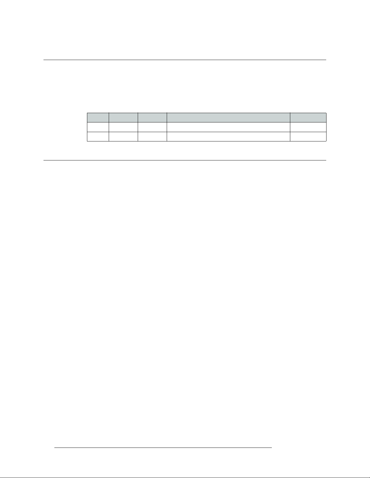
Rev Date ECO Description Approved By
1.0 18 Aug 10 17186 Initial release. Conforms to SE version 6.0.8 D. Cox
Restriction on Hazardous Substances (RoHS)
Miranda is in compliance with EU Directive RoHS 2002/95/EC governing the restricted use of certain hazardous substances and materials in products and in our manufacturing processes.
Miranda has a substantial program in place for RoHS compliance that includes significant investment in our manufacturing process, and a migration of Miranda product electronic components and
structural materials to RoHS compliance.
It is our objective at NV to maintain compliance with all relevant environmental and product regulatory requirements. Detailed information on specific products or on the RoHS program at Miranda
is available from Miranda Customer Support at
1-800-719-1900 (toll-free) or
1-530-265-1000 (outside the U.S.).
iv Rev 1.0 • 18 Aug 10
Page 5
Important Safeguards and Notices
This section provides important safety guidelines for operators and service personnel. Specific
warnings and cautions appear throughout the manual where they apply. Please read and follow this
important information, especially those instructions related to the risk of electric shock or injury to
persons.
Warning
Any instructions in this manual that require opening the equipment cover or
enclosure are for use by qualified service personnel only. To reduce the risk of
electric shock, do not perform any service other than that contained in the
operating instructions unless you are qualified to do so.
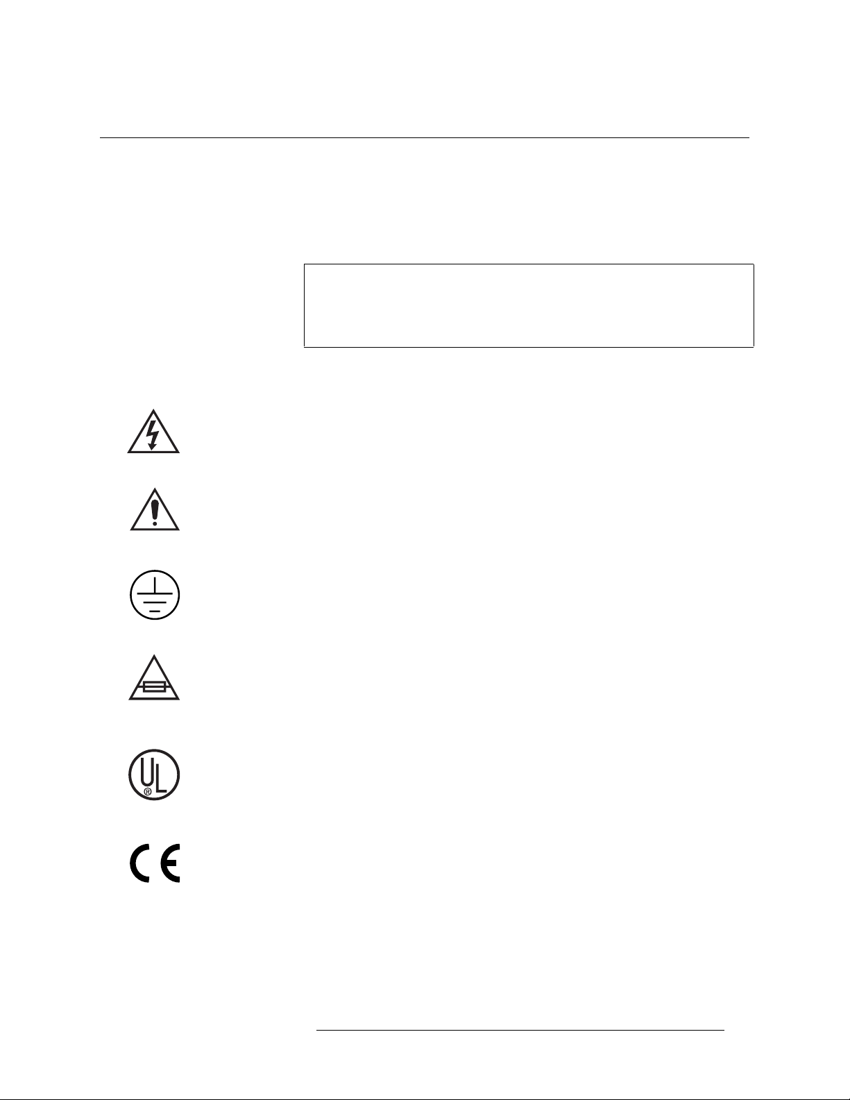
Symbols and Their Meanings
The lightning flash with arrowhead symbol within an equilateral triangle alerts the user to the presence of dangerous voltages within the product’s enclosure that may be of sufficient magnitude to
constitute a risk of electric shock to persons.
The exclamation point within an equilateral triangle alerts the user to the presence of important
operating and maintenance/service instructions.
The Ground symbol represents a protective grounding terminal. Such a terminal must be connected
to earth ground prior to making any other connections to the equipment.
The fuse symbol indicates that the fuse referenced in the text must be replaced with one having the
ratings indicated.
The presence of this symbol in or on Miranda equipment means that it has been designed, tested
and certified as complying with applicable Underwriter’s Laboratory (USA) regulations and recommendations.
The presence of this symbol in or on Miranda equipment means that it has been designed, tested
and certified as essentially complying with all applicable European Union (CE) regulations and
recommendations.
NV9616 Control Panel • User’s Guide v
Page 6

General Warnings
A warning indicates a possible hazard to personnel which may cause injury or death. Observe the
following general warnings when using or working on this equipment:
• Heed all warnings on the unit and in the operating instructions.
• Do not use this equipment in or near water.
• This equipment is grounded through the grounding conductor of the power cord. To avoid electrical shock, plug the power cord into a properly wired receptacle before connecting the equipment inputs or outputs.
• Route power cords and other cables so they are not likely to be damaged.
• Disconnect power before cleaning the equipment. Do not use liquid or aerosol cleaners; use
only a damp cloth.
• Dangerous voltages may exist at several points in this equipment. To avoid injury, do not touch
exposed connections and components while power is on.
• Do not wear rings or wristwatches when troubleshooting high current circuits such as the power
supplies.
• To avoid fire hazard, use only the specified fuse(s) with the correct type number, voltage and
current ratings as referenced in the appropriate locations in the service instructions or on the
equipment. Always refer fuse replacements to qualified service personnel.
• To avoid explosion, do not operate this equipment in an explosive atmosphere.
• Have qualified service personnel perform safety checks after any service.
General Cautions
A caution indicates a possible hazard to equipment that could result in equipment damage. Observe
the following cautions when operating or working on this equipment:
• When installing this equipment, do not attach the power cord to building surfaces.
• To prevent damage to equipment when replacing fuses, locate and correct the problem that
caused the fuse to blow before re-applying power.
• Use only the specified replacement parts.
• Follow static precautions at all times when handling this equipment.
• This product should only be powered as described in the manual. To prevent equipment damage, select the proper line voltage on the power supply(ies) as described in the installation documentation.
• To prevent damage to the equipment, read the instructions in the equipment manual for proper
input voltage range selection.
• Some products include a backup battery. There is a risk of explosion if the battery is replaced by
a battery of an incorrect type. Dispose of batteries according to instructions.
• Products that have (1) no on/off switch and (2) use an external power supply must be installed
in proximity to a main power output that is easily accessible.
vi Rev 1.0 • 18 Aug 10
Page 7

Table of Contents
Chapter 1 Preface. . . . . . . . . . . . . . . . . . . . . . . . . . . . . . . . . . . . . . . . . . . . . . . . . . . . . . . . . . . . . . . . . . . . 1
Chapter Structure . . . . . . . . . . . . . . . . . . . . . . . . . . . . . . . . . . . . . . . . . . . . . . . . . . . . . . . . . . . . . . 1
The PDF Document . . . . . . . . . . . . . . . . . . . . . . . . . . . . . . . . . . . . . . . . . . . . . . . . . . . . . . . . . . . . 1
Terms, Conventions and Abbreviations . . . . . . . . . . . . . . . . . . . . . . . . . . . . . . . . . . . . . . . . . . . . . 2
Other Documentation and Software . . . . . . . . . . . . . . . . . . . . . . . . . . . . . . . . . . . . . . . . . . . . . . . . 2
Notice . . . . . . . . . . . . . . . . . . . . . . . . . . . . . . . . . . . . . . . . . . . . . . . . . . . . . . . . . . . . . . . . . . . . . . . 2
Chapter 2 Introduction. . . . . . . . . . . . . . . . . . . . . . . . . . . . . . . . . . . . . . . . . . . . . . . . . . . . . . . . . . . . . . . 5
Summary . . . . . . . . . . . . . . . . . . . . . . . . . . . . . . . . . . . . . . . . . . . . . . . . . . . . . . . . . . . . . . . . . . . . . 5
Panel Organization . . . . . . . . . . . . . . . . . . . . . . . . . . . . . . . . . . . . . . . . . . . . . . . . . . . . . . . . . . . . . 6
LCD Button Array . . . . . . . . . . . . . . . . . . . . . . . . . . . . . . . . . . . . . . . . . . . . . . . . . . . . . . . . . . 6
Scroll Buttons. . . . . . . . . . . . . . . . . . . . . . . . . . . . . . . . . . . . . . . . . . . . . . . . . . . . . . . . . . . . . . 7
Shortcut . . . . . . . . . . . . . . . . . . . . . . . . . . . . . . . . . . . . . . . . . . . . . . . . . . . . . . . . . . . . . . 7
Function Buttons . . . . . . . . . . . . . . . . . . . . . . . . . . . . . . . . . . . . . . . . . . . . . . . . . . . . . . . . . . . 7
Modes of Operation . . . . . . . . . . . . . . . . . . . . . . . . . . . . . . . . . . . . . . . . . . . . . . . . . . . . . . . . . . . . . 8
Multi-Destination Mode . . . . . . . . . . . . . . . . . . . . . . . . . . . . . . . . . . . . . . . . . . . . . . . . . . . . . 8
X-Y Mode . . . . . . . . . . . . . . . . . . . . . . . . . . . . . . . . . . . . . . . . . . . . . . . . . . . . . . . . . . . . . . . . 8
Secondary Modes . . . . . . . . . . . . . . . . . . . . . . . . . . . . . . . . . . . . . . . . . . . . . . . . . . . . . . . . . . . 9
Other Panel Functions . . . . . . . . . . . . . . . . . . . . . . . . . . . . . . . . . . . . . . . . . . . . . . . . . . . . . . . . . . . 9
Additional Control Panel Features . . . . . . . . . . . . . . . . . . . . . . . . . . . . . . . . . . . . . . . . . . . . . . 9
Chapter 3 Installation . . . . . . . . . . . . . . . . . . . . . . . . . . . . . . . . . . . . . . . . . . . . . . . . . . . . . . . . . . . . . . . 11
Package Contents . . . . . . . . . . . . . . . . . . . . . . . . . . . . . . . . . . . . . . . . . . . . . . . . . . . . . . . . . . . . . 11
Installation . . . . . . . . . . . . . . . . . . . . . . . . . . . . . . . . . . . . . . . . . . . . . . . . . . . . . . . . . . . . . . . . . . . 12
Installing Software and Documentation. . . . . . . . . . . . . . . . . . . . . . . . . . . . . . . . . . . . . . . . . . . . . 12
Initialization . . . . . . . . . . . . . . . . . . . . . . . . . . . . . . . . . . . . . . . . . . . . . . . . . . . . . . . . . . . . . . . . . 12
Testing . . . . . . . . . . . . . . . . . . . . . . . . . . . . . . . . . . . . . . . . . . . . . . . . . . . . . . . . . . . . . . . . . . . . . . 13
Chapter 4 Configuration . . . . . . . . . . . . . . . . . . . . . . . . . . . . . . . . . . . . . . . . . . . . . . . . . . . . . . . . . . . .15
Summary . . . . . . . . . . . . . . . . . . . . . . . . . . . . . . . . . . . . . . . . . . . . . . . . . . . . . . . . . . . . . . . . . . . . 15
Adding a Panel to an NV9000 Configuration . . . . . . . . . . . . . . . . . . . . . . . . . . . . . . . . . . . . . . . . 15
NV9616 Panel Configuration Page . . . . . . . . . . . . . . . . . . . . . . . . . . . . . . . . . . . . . . . . . . . . . . . . 18
Regions of the Configuration Page . . . . . . . . . . . . . . . . . . . . . . . . . . . . . . . . . . . . . . . . . . . . 19
Configuration Tasks . . . . . . . . . . . . . . . . . . . . . . . . . . . . . . . . . . . . . . . . . . . . . . . . . . . . . . . . 19
Commitment Buttons . . . . . . . . . . . . . . . . . . . . . . . . . . . . . . . . . . . . . . . . . . . . . . . . . . . . . . . . . . 19
Panel Options . . . . . . . . . . . . . . . . . . . . . . . . . . . . . . . . . . . . . . . . . . . . . . . . . . . . . . . . . . . . . . . . . 20
Checkbox Options . . . . . . . . . . . . . . . . . . . . . . . . . . . . . . . . . . . . . . . . . . . . . . . . . . . . . . . . . 21
Button Definitions . . . . . . . . . . . . . . . . . . . . . . . . . . . . . . . . . . . . . . . . . . . . . . . . . . . . . . . . . . . . . 24
Button Specification. . . . . . . . . . . . . . . . . . . . . . . . . . . . . . . . . . . . . . . . . . . . . . . . . . . . . . . . 24
Button Types . . . . . . . . . . . . . . . . . . . . . . . . . . . . . . . . . . . . . . . . . . . . . . . . . . . . . . . . . . . . . 25
NV9616 Control Panel • User’s Guide vii
Page 8

Table of Contents
Chapter 5 Operation . . . . . . . . . . . . . . . . . . . . . . . . . . . . . . . . . . . . . . . . . . . . . . . . . . . . . . . . . . . . . . .31
Summary . . . . . . . . . . . . . . . . . . . . . . . . . . . . . . . . . . . . . . . . . . . . . . . . . . . . . . . . . . . . . . . . . . . . 31
Modes of Operation . . . . . . . . . . . . . . . . . . . . . . . . . . . . . . . . . . . . . . . . . . . . . . . . . . . . . . . . 31
Multi-Destination Mode . . . . . . . . . . . . . . . . . . . . . . . . . . . . . . . . . . . . . . . . . . . . . . . . 32
X-Y Mode . . . . . . . . . . . . . . . . . . . . . . . . . . . . . . . . . . . . . . . . . . . . . . . . . . . . . . . . . . . 32
Secondary Modes. . . . . . . . . . . . . . . . . . . . . . . . . . . . . . . . . . . . . . . . . . . . . . . . . . . . . . 33
Button Legends . . . . . . . . . . . . . . . . . . . . . . . . . . . . . . . . . . . . . . . . . . . . . . . . . . . . . . . . . . . 33
Operating Concepts . . . . . . . . . . . . . . . . . . . . . . . . . . . . . . . . . . . . . . . . . . . . . . . . . . . . . . . . . . . . 34
Levels . . . . . . . . . . . . . . . . . . . . . . . . . . . . . . . . . . . . . . . . . . . . . . . . . . . . . . . . . . . . . . . . . . 34
Breakaway . . . . . . . . . . . . . . . . . . . . . . . . . . . . . . . . . . . . . . . . . . . . . . . . . . . . . . . . . . . 34
Hold . . . . . . . . . . . . . . . . . . . . . . . . . . . . . . . . . . . . . . . . . . . . . . . . . . . . . . . . . . . . . . . . . . . . 35
Breakaway . . . . . . . . . . . . . . . . . . . . . . . . . . . . . . . . . . . . . . . . . . . . . . . . . . . . . . . . . . . 35
Multi-Destination Mode. . . . . . . . . . . . . . . . . . . . . . . . . . . . . . . . . . . . . . . . . . . . . . . . . 35
Category Selection . . . . . . . . . . . . . . . . . . . . . . . . . . . . . . . . . . . . . . . . . . . . . . . . . . . . . . . . 35
Lock, Protect, and Release . . . . . . . . . . . . . . . . . . . . . . . . . . . . . . . . . . . . . . . . . . . . . . . . . . . 36
Takes . . . . . . . . . . . . . . . . . . . . . . . . . . . . . . . . . . . . . . . . . . . . . . . . . . . . . . . . . . . . . . . . . . . 37
Scenario 1
Scenario 2 — X-Y Mode, Breakaway . . . . . . . . . . . . . . . . . . . . . . . . . . . . . . . . . . . . . . 37
Scenario 3
Scenario 4 — MD Mode, Multiple Destinations . . . . . . . . . . . . . . . . . . . . . . . . . . . . . . 38
Gang Takes . . . . . . . . . . . . . . . . . . . . . . . . . . . . . . . . . . . . . . . . . . . . . . . . . . . . . . . . . . . . . . 39
Buttons . . . . . . . . . . . . . . . . . . . . . . . . . . . . . . . . . . . . . . . . . . . . . . . . . . . . . . . . . . . . . . . . . . 39
Broadcast . . . . . . . . . . . . . . . . . . . . . . . . . . . . . . . . . . . . . . . . . . . . . . . . . . . . . . . . . . . . 39
Category . . . . . . . . . . . . . . . . . . . . . . . . . . . . . . . . . . . . . . . . . . . . . . . . . . . . . . . . . . . . 39
Chop . . . . . . . . . . . . . . . . . . . . . . . . . . . . . . . . . . . . . . . . . . . . . . . . . . . . . . . . . . . . . . . 40
Clear . . . . . . . . . . . . . . . . . . . . . . . . . . . . . . . . . . . . . . . . . . . . . . . . . . . . . . . . . . . . . . . 40
Clear Preset . . . . . . . . . . . . . . . . . . . . . . . . . . . . . . . . . . . . . . . . . . . . . . . . . . . . . . . . . . 40
Default State . . . . . . . . . . . . . . . . . . . . . . . . . . . . . . . . . . . . . . . . . . . . . . . . . . . . . . . . . 41
Destination Mode . . . . . . . . . . . . . . . . . . . . . . . . . . . . . . . . . . . . . . . . . . . . . . . . . . . . . 41
Destination Lock . . . . . . . . . . . . . . . . . . . . . . . . . . . . . . . . . . . . . . . . . . . . . . . . . . . . . . 41
Destination Protect . . . . . . . . . . . . . . . . . . . . . . . . . . . . . . . . . . . . . . . . . . . . . . . . . . . . 41
Free Source . . . . . . . . . . . . . . . . . . . . . . . . . . . . . . . . . . . . . . . . . . . . . . . . . . . . . . . . . . 42
Gang Take . . . . . . . . . . . . . . . . . . . . . . . . . . . . . . . . . . . . . . . . . . . . . . . . . . . . . . . . . . . 42
Hold . . . . . . . . . . . . . . . . . . . . . . . . . . . . . . . . . . . . . . . . . . . . . . . . . . . . . . . . . . . . . . . . 42
Information . . . . . . . . . . . . . . . . . . . . . . . . . . . . . . . . . . . . . . . . . . . . . . . . . . . . . . . . . . 42
Level Map . . . . . . . . . . . . . . . . . . . . . . . . . . . . . . . . . . . . . . . . . . . . . . . . . . . . . . . . . . . 42
Load Preset . . . . . . . . . . . . . . . . . . . . . . . . . . . . . . . . . . . . . . . . . . . . . . . . . . . . . . . . . . 43
Menu . . . . . . . . . . . . . . . . . . . . . . . . . . . . . . . . . . . . . . . . . . . . . . . . . . . . . . . . . . . . . . . 43
Name Set Toggle . . . . . . . . . . . . . . . . . . . . . . . . . . . . . . . . . . . . . . . . . . . . . . . . . . . . . . 43
Panel Lock . . . . . . . . . . . . . . . . . . . . . . . . . . . . . . . . . . . . . . . . . . . . . . . . . . . . . . . . . . . 43
Preset Release . . . . . . . . . . . . . . . . . . . . . . . . . . . . . . . . . . . . . . . . . . . . . . . . . . . . . . . . 43
Previous Source . . . . . . . . . . . . . . . . . . . . . . . . . . . . . . . . . . . . . . . . . . . . . . . . . . . . . . . 43
Salvo . . . . . . . . . . . . . . . . . . . . . . . . . . . . . . . . . . . . . . . . . . . . . . . . . . . . . . . . . . . . . . . 44
Save Preset . . . . . . . . . . . . . . . . . . . . . . . . . . . . . . . . . . . . . . . . . . . . . . . . . . . . . . . . . . 44
Source . . . . . . . . . . . . . . . . . . . . . . . . . . . . . . . . . . . . . . . . . . . . . . . . . . . . . . . . . . . . . . 44
Source Mode . . . . . . . . . . . . . . . . . . . . . . . . . . . . . . . . . . . . . . . . . . . . . . . . . . . . . . . . . 44
Source is Master. . . . . . . . . . . . . . . . . . . . . . . . . . . . . . . . . . . . . . . . . . . . . . . . . . . . . . . 44
Src/Dst Mode . . . . . . . . . . . . . . . . . . . . . . . . . . . . . . . . . . . . . . . . . . . . . . . . . . . . . . . . . 45
XY/MD Mode . . . . . . . . . . . . . . . . . . . . . . . . . . . . . . . . . . . . . . . . . . . . . . . . . . . . . . . . 45
Undefined. . . . . . . . . . . . . . . . . . . . . . . . . . . . . . . . . . . . . . . . . . . . . . . . . . . . . . . . . . . . 45
Name Sets . . . . . . . . . . . . . . . . . . . . . . . . . . . . . . . . . . . . . . . . . . . . . . . . . . . . . . . . . . . . . . . 45
Broadcast Routes . . . . . . . . . . . . . . . . . . . . . . . . . . . . . . . . . . . . . . . . . . . . . . . . . . . . . . . . . . 46
Making Broadcast Routes . . . . . . . . . . . . . . . . . . . . . . . . . . . . . . . . . . . . . . . . . . . . . . . 46
Removing Broadcast Routes . . . . . . . . . . . . . . . . . . . . . . . . . . . . . . . . . . . . . . . . . . . . . 46
— X-Y Mode, All Level . . . . . . . . . . . . . . . . . . . . . . . . . . . . . . . . . . . . . . . . 37
— Multi-Destination Mode, One Destination . . . . . . . . . . . . . . . . . . . . . . . 38
viii Rev 1.0 • 01 Jul 10
Page 9

Table of Contents
Saving and Loading Presets . . . . . . . . . . . . . . . . . . . . . . . . . . . . . . . . . . . . . . . . . . . . . . . . . 46
How to Save a Preset . . . . . . . . . . . . . . . . . . . . . . . . . . . . . . . . . . . . . . . . . . . . . . . . . . . 46
Using the Save Preset Buttons . . . . . . . . . . . . . . . . . . . . . . . . . . . . . . . . . . . . . . . . . . . . 47
How to Load a Preset . . . . . . . . . . . . . . . . . . . . . . . . . . . . . . . . . . . . . . . . . . . . . . . . . . . 48
Salvo Mode . . . . . . . . . . . . . . . . . . . . . . . . . . . . . . . . . . . . . . . . . . . . . . . . . . . . . . . . . . . . . . . . . . 48
Menu Mode . . . . . . . . . . . . . . . . . . . . . . . . . . . . . . . . . . . . . . . . . . . . . . . . . . . . . . . . . . . . . . . . . . 49
Software Versions Submenu . . . . . . . . . . . . . . . . . . . . . . . . . . . . . . . . . . . . . . . . . . . . . . . . . 49
User Submenu . . . . . . . . . . . . . . . . . . . . . . . . . . . . . . . . . . . . . . . . . . . . . . . . . . . . . . . . . . . . 50
Panel Submenu . . . . . . . . . . . . . . . . . . . . . . . . . . . . . . . . . . . . . . . . . . . . . . . . . . . . . . . . . . . 50
Function Button Illumination . . . . . . . . . . . . . . . . . . . . . . . . . . . . . . . . . . . . . . . . . . . . . . . . 51
LCD Button Illumination . . . . . . . . . . . . . . . . . . . . . . . . . . . . . . . . . . . . . . . . . . . . . . . . . . . 51
Local Salvos Submenu . . . . . . . . . . . . . . . . . . . . . . . . . . . . . . . . . . . . . . . . . . . . . . . . . . . . . 52
Stop Record . . . . . . . . . . . . . . . . . . . . . . . . . . . . . . . . . . . . . . . . . . . . . . . . . . . . . . . . . . 52
Pause Record . . . . . . . . . . . . . . . . . . . . . . . . . . . . . . . . . . . . . . . . . . . . . . . . . . . . . . . . . 52
Save Salvo . . . . . . . . . . . . . . . . . . . . . . . . . . . . . . . . . . . . . . . . . . . . . . . . . . . . . . . . . . . 52
Cancel Salvo . . . . . . . . . . . . . . . . . . . . . . . . . . . . . . . . . . . . . . . . . . . . . . . . . . . . . . . . . 53
Erase Local Salvo. . . . . . . . . . . . . . . . . . . . . . . . . . . . . . . . . . . . . . . . . . . . . . . . . . . . . . 53
Using the Salvo Naming Buttons . . . . . . . . . . . . . . . . . . . . . . . . . . . . . . . . . . . . . . . . . . 53
Setup Mode . . . . . . . . . . . . . . . . . . . . . . . . . . . . . . . . . . . . . . . . . . . . . . . . . . . . . . . . . . . . . . . . . . 54
Setting the Panel ID . . . . . . . . . . . . . . . . . . . . . . . . . . . . . . . . . . . . . . . . . . . . . . . . . . . . . . . . 55
Viewing the Software Versions . . . . . . . . . . . . . . . . . . . . . . . . . . . . . . . . . . . . . . . . . . . . . . . 56
Panel Test Mode. . . . . . . . . . . . . . . . . . . . . . . . . . . . . . . . . . . . . . . . . . . . . . . . . . . . . . . . . . . 56
Chapter 6 Technical Details . . . . . . . . . . . . . . . . . . . . . . . . . . . . . . . . . . . . . . . . . . . . . . . . . . . . . . . . . 57
Power Specifications . . . . . . . . . . . . . . . . . . . . . . . . . . . . . . . . . . . . . . . . . . . . . . . . . . . . . . . . . . . 57
NV9616 and NV9608 Specifications. . . . . . . . . . . . . . . . . . . . . . . . . . . . . . . . . . . . . . . . . . . . . . . 58
Environmental Specifications . . . . . . . . . . . . . . . . . . . . . . . . . . . . . . . . . . . . . . . . . . . . . . . . . . . . 58
Defaults . . . . . . . . . . . . . . . . . . . . . . . . . . . . . . . . . . . . . . . . . . . . . . . . . . . . . . . . . . . . . . . . . . . . . 59
Initial Panel State . . . . . . . . . . . . . . . . . . . . . . . . . . . . . . . . . . . . . . . . . . . . . . . . . . . . . . . . . 59
Configuration Page . . . . . . . . . . . . . . . . . . . . . . . . . . . . . . . . . . . . . . . . . . . . . . . . . . . . . . . . 59
DHCP . . . . . . . . . . . . . . . . . . . . . . . . . . . . . . . . . . . . . . . . . . . . . . . . . . . . . . . . . . . . . . . . . . 59
Drawings . . . . . . . . . . . . . . . . . . . . . . . . . . . . . . . . . . . . . . . . . . . . . . . . . . . . . . . . . . . . . . . . . . . . 59
Chapter 7 Misc. Topics . . . . . . . . . . . . . . . . . . . . . . . . . . . . . . . . . . . . . . . . . . . . . . . . . . . . . . . . . . . . . . 63
Glossary . . . . . . . . . . . . . . . . . . . . . . . . . . . . . . . . . . . . . . . . . . . . . . . . . . . . . . . . . . . . . . . . . . . . 63
Setting the Timeout Value . . . . . . . . . . . . . . . . . . . . . . . . . . . . . . . . . . . . . . . . . . . . . . . . . . . . . . . 65
Index . . . . . . . . . . . . . . . . . . . . . . . . . . . . . . . . . . . . . . . . . . . . . . . . . . . . . . . . . . . . . . . . . . . . . . . . . .67
NV9616 Control Panel • User’s Guide ix
Page 10

Table of Contents
x Rev 1.0 • 01 Jul 10
Page 11

1. Preface
Chapter 1 is an introduction to the NV9608 and NV9616 User’s Guide. It presents the following
topics:
• Chapter Structure
• The PDF Document
• Terms, Conventions and Abbreviations
Chapter Structure
The following chapters provide detailed information regarding the NV9616 Control Panel:
• Chapter 1, Preface
• Chapter 2, Introduction
• Chapter 3, Installation
• Chapter 4, Configuration
This chapter is for configurers, primarily.
• Chapter 5, Operation
This chapter is for operators, primarily.
• Chapter 6, Technical Details
product drawings, and default settings.
• Chapter 7, Misc. Topics
, (this chapter) outlines ways to use this guide.
, provides a functional description of the NV9616.
, provides installation, connection, and initialization instructions.
, provides configuration instructions.
, provides operating instructions.
, provides electrical, mechanical, and environmental specifications,
, presents a glossary and miscellaneous instructions and information.
•An Index
is also provided for your reference.
The PDF Document
This guide is provided in PDF format, allowing you to use Acrobat’s “bookmarks” to navigate to
any desired location. You can also easily print a hardcopy. Please note:
• Use the Table of Contents or the bookmarks page to jump to any desired section.
• Many hyperlinks are provided within the chapters.
• Use the Index to jump to specific topics within a chapter. Each page number in the index is a
hyperlink.
• Use Acrobat’s ‘Go to Previous View’ and ‘Go to Next View’ buttons to retrace your complete
navigational path.
NV9616 Control Panel • User’s Guide 1
Page 12

1. Preface
Terms, Conventions and Abbreviations
• Use the ‘First Page’, ‘Previous Page’, and ‘Next Page’, and ‘Last Page’ buttons to go to the
first, previous, next, or last page within a PDF file.
Note
• Use Acrobat’s extensive search capabilities, such as the ‘Find’ tool and ‘Search’ tool to perform
comprehensive searches as required.
To display the navigation buttons, right-click the Tool Bar area, and check
‘Navigation’.
Terms, Conventions and Abbreviations
The following conventions are used throughout this guide:
• The symbol
• Entries enclosed in single quotation marks or C
tons, configuration buttons, or menu items.
• Click ‘Apply’ to ...
• Press the SRC
The following terms and abbreviations are used throughout this guide:
• The terms “panel” and “control panel” refers to the NV9616 and NV9608 control panels and to
NV96xx control panels, in general.
• “High tally” means that a button is brightly illuminated. High-tally usually means that the button function is selected or active.
• “Low tally” means that a button is illuminated at low intensity. Most buttons assume a low tally
state until selected.
• “SE” is an abbreviation used in this document for NV9000-SE Utilities.
S denotes either an example or a special message.
12 button ...
apital Letters denote physical control panel but-
Other Documentation and Software
You should read and be familiar with the material presented in the following documents:
• NV9000 Quickstart Guide.
• NV9000-SE Utilities User’s Guide (or NV9000-SE Utilities help files).
• The router manuals for whatever routers you have in your system.
You should also be familiar with the NV9000-SE Utilities software and NV9000 or NV915 router
control systems.
Notice
Certain features of the NV9616 and NV9608 are not supported in NV915 control systems:
• Saving presets and loading presets.
• Local salvos.
These features are fully supported in NV9000 control systems.
2 Rev 1.0 • 01 Jul 10
Page 13

1. Preface
Notice
NV9616 Control Panel • User’s Guide 3
Page 14

1. Preface
Notice
4 Rev 1.0 • 01 Jul 10
Page 15
2. Introduction
Chapter 2 provides a functional description of the NV9616 and NV9608 control panels. It presents
these topics:
• Summary
• Panel Organization
• Modes of Operation
• Other Panel Functions
Summary
The NV96161 and NV9608 are 2RU control panels, 9.25″ deep. The NV9616 has 16 LCD buttons
whereas the NV9608 has 8 LCD buttons. Otherwise, they are functionally identical. (The NV9608
is less expensive.)
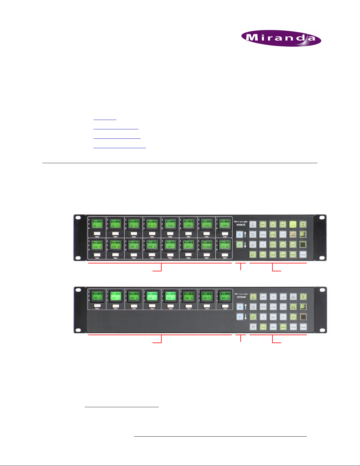
The panels are organized as shown in figures 2-1, 2-2, and 2-3:
Scroll Buttons (2)
Figure 2-1. NV9616 Front Views
Scroll Buttons (2)
Figure 2-2. NV9608 Front Views
The panels can operate in one of 2 modes:
•X-Y mode.
• Multidestination mode.
The panels can be configured so that either mode is selectable by the operator. The panels can also
operate in several secondary modes, including salvo mode and menu mode.
1 An equivalent NV9616V — a GUI that is called a “virtual panel”— is available. It emulates the NV9616. There is no
NV9608V.
NV9616 Control Panel • User’s Guide 5
Function Buttons (24)LCD Button Array (16)
Function Buttons (24)LCD Button Array (16)
Page 16
2. Introduction
CAM100
VTR 20
MON 4
CAM 1
VTR 20
MON 4
Panel Organization
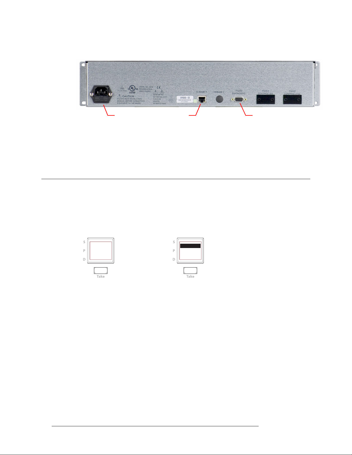
At the rear are power, serial, and network connectors:
Figure 2-3. NV9616 and NV9608 Rear
The ports labeled 10base2 and RS-422 are non-operational and are covered. Only the serial port
and the Ethernet port are available.
S The AC connector has a compartment in which you can find a spare fuse.
(The Ethernet port is 10baseT. The NV9000 supports 10baseT as well as 100baseT.)
Panel Organization
Ethernet (RJ-45) Serial port (RS-232)Power (AC)
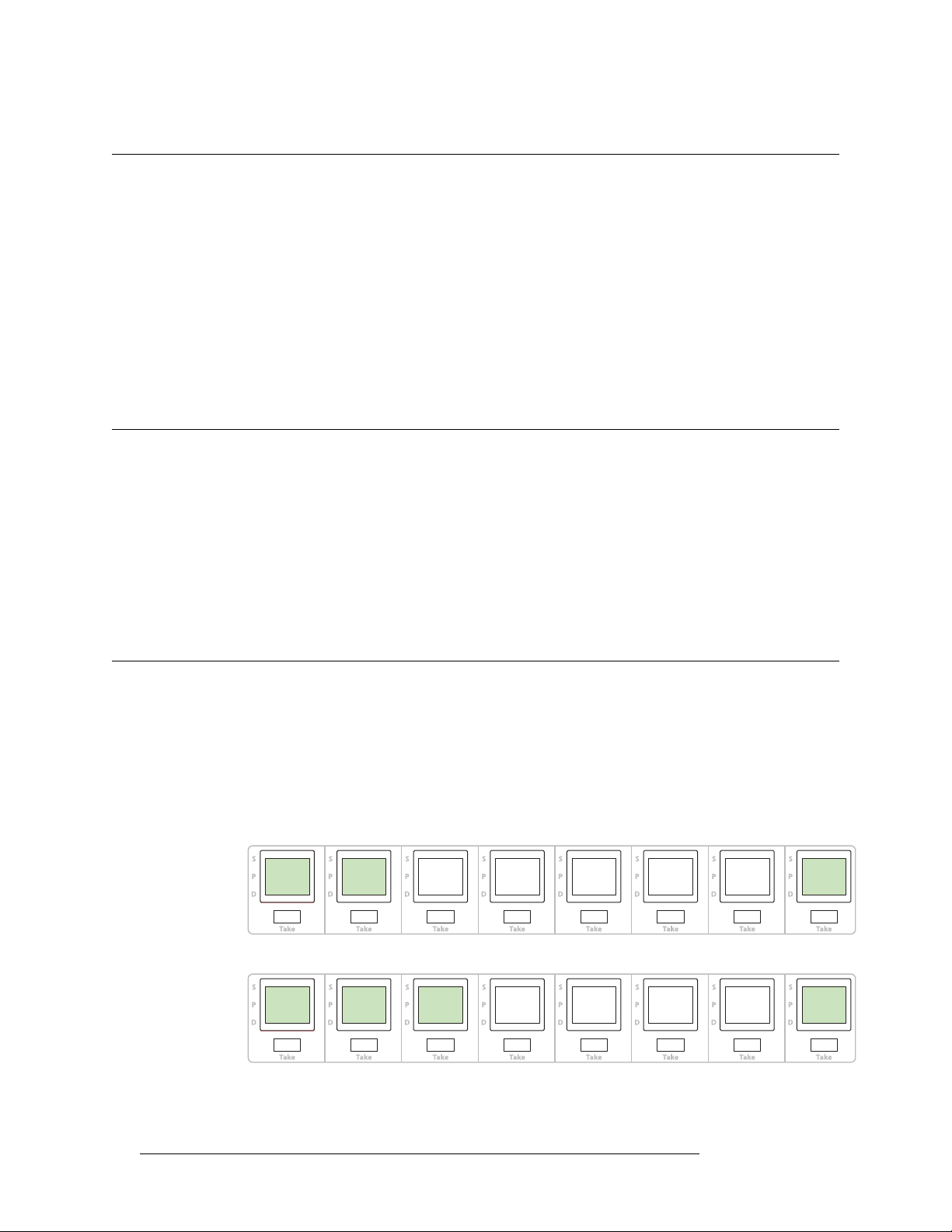
LCD Button Array
The NV9616 has 16 LCD button units. The NV9608 has 8. Each unit comprises a large LCD button
and a small ‘Take’ button below the LCD button. The LCD buttons each have 3 lines of text (up to
8 characters per line). The lines of the button are labeled “S,” “P,” and “D” on the panel:
CAM100
VTR 20
MON 4
In multi-destination mode, the 3 lines of text display status (S), preset (P), and destination (D),
respectively. If breakaway applies to that destination, the status apppears in reverse text. A button
can display other messages in other contexts.
Under each LCD button is a smaller white ‘Take’ button. Pressing the take button executes a take
for the selected destination. The methods for selecting destinations and sources for the take are different in X-Y mode and multi-destination (MD) mode.
The LCD button array represents:
• Destinations (in multi-destination mode). The panels provide support for up to 512 MD destinations. You can select different “pages” of destinations using the scroll buttons.
• Levels (in X-Y mode). The button at the top left represents the selected destination. The
remaining 15 buttons (or 7 buttons on the NV9608) buttons represent the levels of the selected
destination.
• Menu functions (in menu mode). Some of the LCD buttons execute menu functions.
• Salvos (in salvo mode). The panels provide support for system salvos and local salvos on multiple pages of salvo buttons. You can select a “page” of salvos using the scroll buttons.
All-Level Breakaway
VTR 20
MON 4
6 Rev 1.0 • 01 Jul 10
Page 17

2. Introduction
Panel Organization
Scroll Buttons
There are two scroll buttons (called ‘Page Up’ and ‘Page Down’ in the configuration software).
These buttons scroll either through pages of MD destinations or through pages of salvos. The scroll
buttons page through levels if you have more than 15 (or 7) levels defined.
Scrolling of MD destinations wraps around at the ends of the MD destination list if ‘Use Continuous Scrolling’ is enabled. At the head of the list, ‘Page Up’ causes the last page to display. At the
end of the list, ‘Page Down’ causes the first page to display. If ‘Use Continuous Scrolling’ is not
enabled, the pages stop scrolling at the ends of the list.
Continuous scrolling is a panel default.
Continuous scrolling does not apply to the salvo list and does not apply to levels in X-Y mode.
Shortcut
In MD mode, the panel’s category buttons allow you to enter a page number for multi-destination
devices, instead of scrolling. This is a convenience
‘Page Up’ button presses when you know the number of the page you want.
Note:
• The shortcut is available only when no category device selection is pending (in MD mode).
• Only category buttons that have single-digit suffixes are enabled.
• The shortcut is not available for salvo pages.
— a shortcut that lets you avoid ‘Page Down’ or
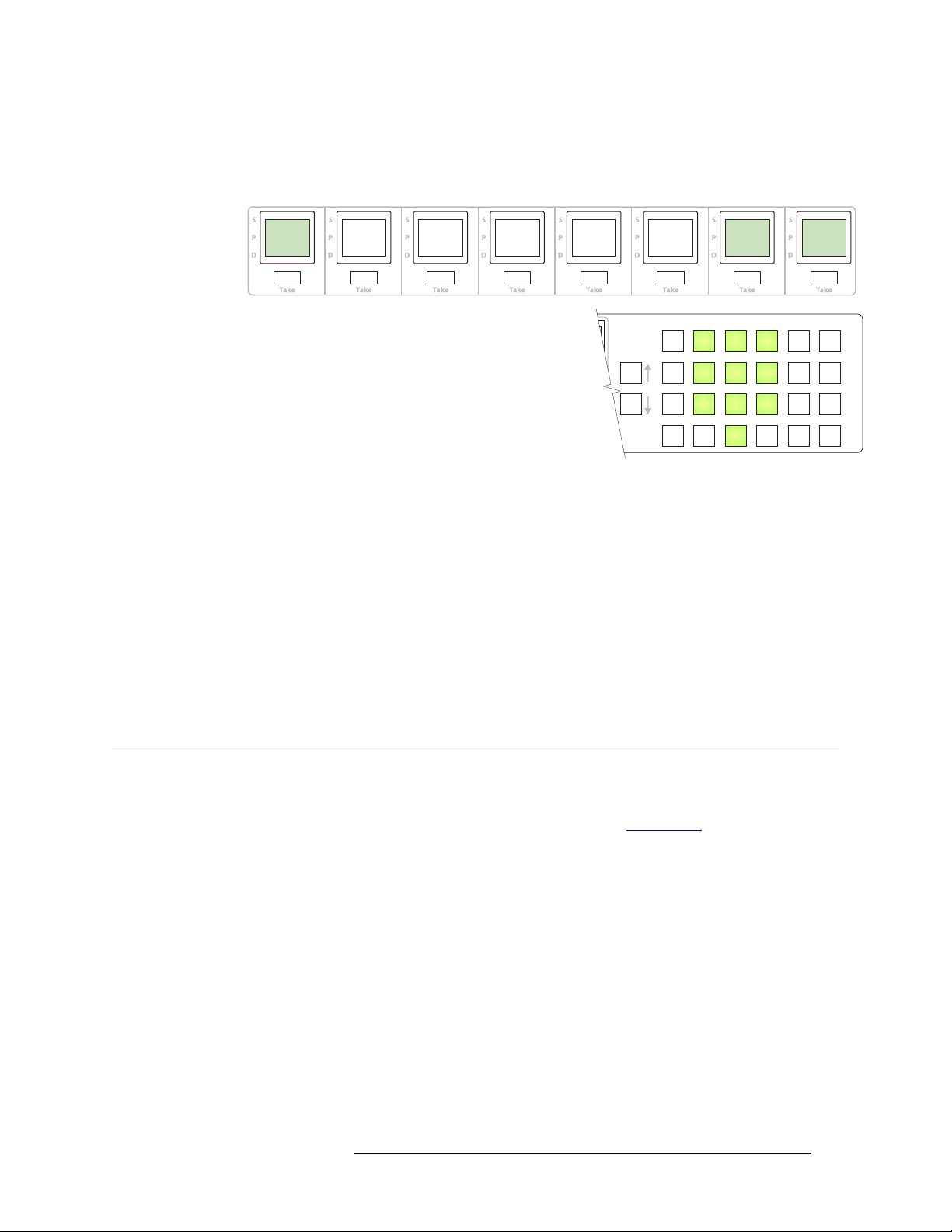
Function Buttons
The NV9616 and NV9608 have an array of 24 function buttons on the right.
Of those, 10 buttons, arranged like a telephone keypad, have fixed functions. These 10 buttons are
“category” buttons, representing category mnemonics or category suffixes or both:
The ordering of suffixes and mnemonics on these fixed buttons is arbitrary. See Category Selection
on page 35 for more information.
The other 14 function buttons can be assigned any available function.
The set of available functions (28) is the same in X-Y mode and MD mode.
NV9616 Control Panel • User’s Guide 7
Page 18

2. Introduction
Modes of Operation
Modes of Operation
The panels can operate in one of 2 modes:
•X-Y mode.
• Multi-destination (MD) mode.
The panels can be configured so that either mode is selectable by the operator.
Multi-Destination Mode
The panel supports up to 512 MD destinations. The NV9616 displays 16 at a time on the LCD buttons. The NV9608 displays 8 at a time.
Operators perform a take by (optionally) scrolling to an MD page, pressing an LCD button to select
a destination, selecting a source, and pressing the take button under the selected LCD button. The
operator uses the function buttons to select a source. See Category Selection
information.
In MD mode, the LCD buttons are generally green
yellow when you have selected a source and red when you have locked or protected a destination.
Breakaway is not directly possible in MD mode, but when the operator performs breakaway in X-Y
mode and then switches to MD mode, the destination(s) for which breakaway occurred show the
device name in reverse text.
on page 35 for more
— and high-tally when selected. They become
X-Y Mode
The LCD buttons represent a single selected destination and the levels for that destination.
The destination appears on the top left LCD button (for the NV9616). On the NV9608, it is simply
the left button. This button is generally amber. It also displays the text “X - Y” and “Dest” to
remind operators that the panel is in X-Y mode. The button is red when the destination is locked.
The remaining LCD buttons show the levels. The level buttons are generally green
when selected. Level buttons turn yellow when you have selected a source on those levels. If there
are fewer levels than available buttons, the extra buttons are blank. If there are more levels than
available buttons, the operator can scroll through the pages of levels using the scroll buttons. The
destination button remains in its fixed position regardless of the page.
Breakaway is possible in X-Y mode. Operators may select the levels for which the take is to occur
by pressing the individual LCD buttons that represent the levels. (Scrolling might be necessary to
view all the levels.)
Operators perform a take by selecting a destination, (optionally) selecting levels, selecting a source,
and pressing the take button under any of the selected LCD buttons. The operator uses the function
buttons to select a source and to select a destination. See Category Selection
information.
— and high-tally
on page 35 for more
8 Rev 1.0 • 01 Jul 10
Page 19

2. Introduction
Other Panel Functions
Secondary Modes
Additional but secondary modes of panel operation are:
• Setup mode
this mode, you can preset the panel ID and perform a few diagnostic tasks.
• Salvo mode
the operator will choose a salvo on the LCD button, possibly scrolling to find the salvo. (The
duration of a salvo is indeterminate, but usually short.)
• Menu mode
buttons lose their normal functions and become part of a menu that changes as needed during
menu operation.
• Source mode
where the operator can use category and suffix buttons to select a source.
• Destination mode
tion mode, where the operator can use category and suffix buttons to select a destination.
• Hold mode
effect until the operator turns hold mode off. In MD mode, when hold mode is active, the operator may select multiple destinations.
• Save preset mode and load preset mode
temporary mode in which you can name and save a preset selection. Pressing a ‘Load Preset’
button places the panel in a temporary mode in which you can select a saved preset selection.
When the panel is not in setup mode, salvo mode, or menu mode, we say it is in normal mode.
— where the panel is freshly powered up, but disconnected from the network. In
— pressing a salvo button places the panel in salvo mode, where it is expected that
— pressing a menu button places the panel in “menu” mode. In menu mode, the
— pressing a source mode button places the panel temporarily in source mode,
— pressing a destination mode button places the panel temporarily in destina-
— when hold mode is active in X-Y mode, a breakaway level selection remains in
— pressing a ‘Save Preset’ button places the panel in a
Other Panel Functions
The NV9616 and NV9608 can be configured to perform the following additional functions:
• Previous source and free source.
• System salvos and local salvos.
• Lock/protect/release for destinations.
• Multiple- and single-level breakaway.
• Broadcast data routing.
• “Gang” takes.
Additional Control Panel Features
The panel supports gang switching in multi-destination mode. The operator may route single or
multiple sources to multiple destinations in a single operation.
The LCD buttons can be green (for sources), amber (for destinations), yellow, or red. Each button
provides three levels of tally: off, low, and high. Through the menu, high tally can be set at high or
medium brightness and low tally can be set at low or medium brightness, where high tally is constrained to be brighter than low tally.
The panel’s 24 function buttons and two scroll buttons are backlit. The buttons can be green or
amber. Each button provides three levels of tally: off, low, and high. (You can adjust the levels of
NV9616 Control Panel • User’s Guide 9
Page 20

2. Introduction
Other Panel Functions
low and high tally, through the menu. LED brightness levels range from 0% to 100%, in 10% increments, with high tally constrained to be brighter than low tally.)
If you assign an X-Y/Multi-Destination button on your panel, it is a toggle: press it once to place
the panel in X-Y mode and press it again to place the panel in multi-destination mode. (It turns
green for X-Y mode and amber for multi-destination mode.)
10 Rev 1.0 • 01 Jul 10
Page 21

3. Installation
Chapter 3 provides installation and connection instructions. It presents the following topics:
• Package Contents
• Installation
• Installing Software and Documentation
• Installation
• Testing
Package Contents
If you have ordered one or more NV9616 or NV9608 control panels from Miranda, inspect the
shipping container for damage. If you find any container damage, unpack and inspect the contents.
If the contents are damaged, notify the carrier immediately.
As you unpack the shipping container, look for the packing slip and compare it against the contents
to verify that you received everything as ordered. If anything is missing (or if you find equipment
damage unrelated to shipping), please contact technical support. Refer to Technical Support Con-
tact Information on page iii.
Depending on your order, the items that can ship include:
• One or more NV9616 or NV9608 control panels.
• One or two power supplies for each panel, with straps that secure the AC power cords to the
power supplies.
• Optional WC0053 breakout cable.
The package does not contain network cables, serial cables, or mounting screws.
You do not need to take any special precautions regarding ESD.
This document does not address the shipment or installation of any other equipment or software
that can be used in conjunction with the panel (including the NV9000 system controller, NV915
system controller, other NV96xx control panels, EC9700 GUI, EC9710 GUI, and configuration
programs such as UniConfig or NV9000-SE Utilities).
This document does briefly address the use of NV9000-SE Utilities and the Panel IP Configuration
Utility as they pertain to panel configuration.
NV9616 Control Panel • User’s Guide 11
Page 22
3. Installation
NV9616
PANEL ID
0
ACQUIRE
IP
ADDRESS
MENU
PANEL
ID ENTRY
SOFTWARE
VERSIONS
PANEL
TEST
MODE
EXIT
Installation
Installation
Follow these steps to install a NV9616 or NV9608 control panel:
1 Mount, and secure, the panel in the rack.
The NV9616 and NV9608 are designed to mount in a 19″ rack. Rack-mounting is not a requirement.
2 We assume that you have an Ethernet switch connected to the “Panel and Router Network” port
of your system controller. Connect an Ethernet cable from that switch to the RJ-45 port at the
rear of the panel.
3 Connect power.
Installing Software and Documentation
This document is available through the Miranda web site.
You must use NV9000-SE Utilities to configure the NV9616 or NV9608 control panel. Contact
Miranda if you need to obtain the latest version of this NV9000 configuration software.
You may use the Panel IP Configuration Utility if you want to your panel to have a static IP address
(with respect to the NV9000) or to use DHCP. The panel, as it comes from the factory, defaults to
DHCP.
Initialization
Before your NV9000 system controller can communicate with your panel, you must give it a panel
ID. Follow these steps for each NV9616 you are installing:
1 Power up the panel. Do not connect its Ethernet cable. (Disconnect it if it is connected.)
After a few seconds, the LCD buttons will show ‘Acquire IP Address’ on the seond button and
the panel’s current panel ID on the first button. The right-hand button is designated the menu
button:
NV9616
PANEL ID
0
ACQUIRE
IP
ADDRESS
2 Press the menu button. The menu appears:
PANEL
ID ENTRY
SOFTWARE
VERSIONS
PANEL
TEST
MODE
MENU
EXIT
The menu has three submenus. Press the ‘Panel ID Entry’ button.
12 Rev 1.0 • 18 Aug 10
Page 23
3. Installation
PANEL
ID
6061
CANCEL
SAVE
123
456
789
0
Testing
3 The panel now allows you to enter the panel ID using the panel’s standard numeric keypad (the
same as the fixed category buttons when the panel is operating under the NV9000 system). The
ID you enter is displayed on the first button:
PANEL
ID
6061
The numbers of the keypad
are shown here
After you enter the panel ID using the keypad, press ‘Save’. You can press ‘Cancel’ if you make
a mistake.
The panel returns to the menu, at which point you should click ‘Exit’.
4 The second LCD button should display ‘Acquire IP Address’ once again as in step 1.
5 When you finish, reconnect the Ethernet cable. The NV9000 system controller will detect your
panel in a few seconds. (All panel IDs must be unique.)
You can now prepare an NV9616 or NV9608 configuration in NV9000-SE Utilities and upload the
configuration to the NV9616 or NV9608. You need the panel ID to create a panel configuration.
When you upload the configuration, the panel ID you entered in NV9000-SE Utilities designates
the actual panel to which the upload will occur. If no actual panel has that ID, the upload cannot
occur.
CANCEL
SAVE
Testing
A panel test function is available when the NV9616 or NV9608 is disconnected from the system
controller. Run the test to determine the health of your panel. See Setup Mode
You can also view the software version numbers under setup mode.
These are points to consider after you install your control panel(s):
1 Do the buttons illuminate? When an NV9616 or NV9608 powers up, one or more of its buttons
are supposed to turn green or amber. Does it pass the panel test mentioned above?
2 When the NV9616 or NV9608 powers up and it is connected to the system controller, it should
initialize completely. (That takes a few seconds.) The NV9000 system should load whatever
configuration exists for that panel and the buttons appropriate for its configuration should light.
If you continue to see “No Server,” “Acquire IP Address,” or “Locating Network,” you have a
problem. Reboot everything and try again.
S The panel, by default, acquires its IP address through DHCP on the NV9000’s panel/router
network. You can use the Panel IP Configuration Utility to force the panel to have a static IP
address.
NV9616 Control Panel • User’s Guide 13
on page 54 for detail.
Page 24

3. Installation
Testing
If (in setup mode) you do not see your designated panel ID on the first LCD button, you have
either not initialized the panel or no configuration has been created for your panel in NV9000SE Utilities.
3 Is the NV9000 system controller actually running? With the typical noise levels in a facility, it
can sometimes be difficult to tell. Use the ‘System’ pages of NV9000-SE Utilities to make the
determination.
4 Is NV9000-SE Utilities installed and operating? If so, can you upload a configuration to the
specified panel?
5 Does the configuration actually work? Is it useful? Can the operator perform takes and perform
other operations?
You might want to consider how well your operator interface works in addition to the basic question of whether it works.
14 Rev 1.0 • 18 Aug 10
Page 25

4. Configuration
Chapter 4 provides configuration instructions for the NV9616 or NV9608. It presents the following
topics:
• Summary
• Adding a Panel to an NV9000 Configuration
• NV9616 Panel Configuration Page
• Commitment Buttons
• Panel Options
• Button Definitions
This chapter addresses configurers. Operators and other persons not interested in NV9616 configuration need not read this chapter.
Summary
The NV9616 and NV9608 are relatively complex panels. Both have 24 configurable function buttons and 2 dedicated scroll buttons. The NV9616 has 16 LCD button units; the NV9608 has 8.
Among the function buttons is a fixed set of 10 category buttons. You cannot configure these buttons as any other type of button. You can create additonal category buttons however. Category buttons provide category mnemonics or category suffixes, or both, and support device selection using
categories and suffixes for sources and for destinations.
The panels have dedicated take buttons. The NV9616 has 16 and the NV9608 has 8. The take buttons are part of the LCD button units. They operate differently in X-Y mode and MD mode.
NV9000-SE Utilities is the software with which to configure the NV9616. Figure 4-1, following,
shows the default NV9616 panel configuration page from NV9000-SE Utilities.
Adding a Panel to an NV9000 Configuration
You must create configurations for the NV9616 and NV9608 using NV9000-SE Utilities. We
assume that you are familiar enough with NV9000-SE Utilities that you can understand the following material. It is not difficult material, but some of the concepts might not be familiar to everyone.
It takes only a few seconds to add a new panel configuration.
NV9616 Control Panel • User’s Guide 15
Page 26
4. Configuration
Adding a Panel to an NV9000 Configuration
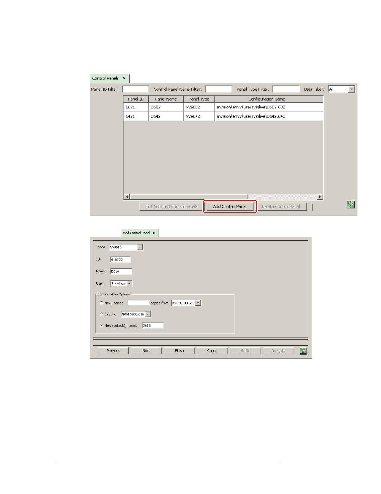
After launching NV9000-SE Utilities, choose ‘Control Panels’ from the Configuration pane in the
navigation area. The ‘Control Panels’ configuration page appears:
Click ‘Add Control Panel’ at the bottom of the page. The ‘Add Control Panel’ page appears:
Choose “NV9616” or “NV9608” from the ‘Type’ field. This illustration shows the addition of an
NV9616. In the ID field, enter the panel ID you assigned to the panel while it was in setup mode.
(You can change the panel ID in NV9000-SE Utilities.) Give a name to the panel in the name field
and select a user.
When you are creating a panel configuration you have 3 options. These options are presented in the
‘Configuration Options’ area:
1 Make a copy of an existing configuration file, giving it a new file name.
2 Use an existing configuration file. (This allows several panels to share a single configuration.)
3 Create an entirely new configuration file.
16 Rev 1.0 • 01 Jul 10
Page 27

4. Configuration
Adding a Panel to an NV9000 Configuration
In the first and third cases, you will create a new configuration file whose name you designate. The
file extension for an NV9616 configuration file is
ration file is
.608. Click ‘Next’ or ‘Finish’ to proceed. Click ‘Previous’ to go back the previous
page. Click ‘Cancel’ to terminate the entry operation.
S There are 2 other buttons, ‘Suffix’ and ‘Navigate’, both dim (disabled). These do not apply to
the NV9616 or NV9608.
Return to the ‘Control Panels’ page to view your new entry. To edit an NV9616 or NV9608 configuration, double-click its list entry. This illustrates the addition of an NV9616:
.616. The file extension for an NV9608 configu-
You will then see the panel configuration page for the selected panel.
The following section of this guide discusses using the panel configuration page in which you configure an NV9616 or NV9608.
NV9616 Control Panel • User’s Guide 17
Page 28

4. Configuration
NV9616 Panel Configuration Page
NV9616 Panel Configuration Page
This is the default NV9616 panel configuration page in NV9000-SE Utilities:
Panel Image:
Button
Definition
Section
Panel
Options
Figure 4-1. NV9616 Configuration Page (Default)
The NV9608 configuration page is functionally identical, but instead of showing 16 LCD button
proxies, it shows only 8.
After you configure buttons the appearance of the panel buttons will have changed. The panel buttons on the configuration page will show legends, determined from the button type assigned to the
button. (The actual panel’s 26 small buttons have removable clear plastic keycaps under which you
can insert button legends, graphic or text, of your own design.)
18 Rev 1.0 • 01 Jul 10
Page 29

4. Configuration
Commitment Buttons
At the bottom of the page are two important configuration buttons: ‘Revert to Saved’ and ‘Save’.
The ‘Save’ button commits modifications you have just made. The ‘Revert to Saved’ button
restores the last saved version of the panel configuration, canceling any changes you just made.
Regions of the Configuration Page
Above the ‘Revert to Saved’ and ‘Save’ buttons (always present) there are 4 main regions:
• A graphic representation of the panel (NV9616 or NV9608).
Configurers must click a button “proxy” to select the button for configuration.
At the left are the 16 (or 8) LCD button proxies. These represent either MD destinations or salvos. You can click the line of text in the middle of this section to toggle between MD destination entry and salvo entry. The text changes accordingly:
If you are configuring more than 16 (or 8) MD destinations, you must click the ‘Page Up’ and
‘Page Down’ button proxies to scroll to a different page to select those MD destinations. Similarly you can scroll through pages of salvo button definitions.
At the right are the 24 function buttons. The 10 yellow buttons are fixed category buttons. You
cannot change the button type of these buttons. The other 14 function buttons are completely
configurable.
• Button definitions.
In this section, configurers make button assignments, using its pull-down menus and text fields.
See Button Definitions
• Panel options.
In this section, configurers may specify the behavioral characteristics of the panel. See Panel
Options, following.
, following.
Configuration Tasks
The person configuring an NV9616 or NV9608 panel will want to consider how best to use the buttons to support the devices and routers in the router control system at hand. The task is non-trivial.
In support of that effort, the configurer will do the following:
• Select panel options.
• Assign functions to buttons.
Commitment Buttons
Two buttons at the bottom of the configuration page are self-explanatory and appear on most configuration pages:
• Revert to Saved. Press this button if you want to discard any recent changes you have made.
• Save. Press this button to commit all your recent changes.
Neither of these actions is reversible.
NV9616 Control Panel • User’s Guide 19
Page 30

4. Configuration
Panel Options
Panel Options
The panel options section, at the right of the configuration page, has two parts: drop-down menus
and checkbox options. These are the drop-down menus:
These are its drop-down menu options:
Panel Type XY/Multi-
Default Mode X-Y Mode Starts the panel in X-Y mode after a reset.
Release Mode Normal Release This panel can release “locks” and “protects” set by the designated
Default
Destination
Preset Monitor None The preset source video is not sent to a monitor.
Status Monitor None The current source video is not sent to a monitor.
destination Modes
XY only The panel configuration is restricted to X-Y mode.
Multi-destination
only
Multi-Dest Mode Starts the panel in multi-destination mode after a reset.
Force Release This panel can release locks and protects set by any user.
None After a reset, the panel displays no destination device. (This is not
‹device› The Panel uses the specified device as the destination after a reset.
‹device› The preset source video for the selected destination appears on the
‹device› The current source video for the selected destination appears on the
The panel configuration allows the operator to switch between X-Y
mode and multi-destination mode at any time.
The panel configuration is restricted to multi-destination mode.
a
user (at this panel or any other panel).
recommended.)
(The ‘Default State’ button also returns the panel to this destination.)
specified monitor (device).
specified monitor (device).
20 Rev 1.0 • 01 Jul 10
Page 31

4. Configuration
Panel Options
XY Data
Routing Mode
MD Data
Routing Mode
Default Name Set System Name A list of “name sets” appears in the drop-down menu. The name sets
Multidest Device
Limit
Automatic If a machine control (data) level is involved in the route, make the
Semi-automatic
(recommended)
Manual A take on the data level must be performed manually as a breakaway
Automatic If a data level is involved in the multi-destination route, connect the
Manual All multi-destination takes on the data level must be performed
16 (or 8) This scroll box allows you to specify the maximum number of MD
route on the control level even if the control port is in use on the
source or destination device.
If the machine control port is in use on the source or destination
device, take all levels except control and allow the user to perform
the control level route by pressing ‘Take’ a second time. If ‘Take’ is
not pressed again, the route is cancelled.
If the control port is not in use, the control level take occurs
automatically.
on the control level. The control level will never switch as part of a
multi-level take.
source to the destinations, regardless of who is currently using the
devices. (Recommended.)
manually as breakaways. The data level will never switch as part of a
multi-level take.
can be defined under the System Management pane of NV9000-SE
Utilities. Choose ‘System Name’ in this list if you do not want, or do
not care about, device name aliases. Do not choose ‘System Name’ if
you are configuring any ‘Name Set Toggle’ buttons.
devices, up to 512. The values increment or decrement by 16 for the
NV9616 and by 8 for the NV9608. The default value is the minimum
value which is 16 for the NV9616 and 8 for the NV9608.
a. See Defaults on page 77.
Checkbox Options
The checkbox options section is at the bottom of the panel options section:
A check in the box enables the option. Clearing the checkbox disables the option.
By default, all the check box options are clear except ‘Use Continous Scrolling’.
NV9616 Control Panel • User’s Guide 21
Page 32

4. Configuration
Panel Options
The following items are the checkbox options:
• User-programmable ID.
• Hold preset default.
• Enable destination lock.
• Enable destination protect.
• Source master default.
• Hide sources not configured on this panel.
• Deselect all destinations and turn off hold after take.
• Jump to multi-dest selection when switching to XY.
• Flip-flop source to preset after take.
Allows the Panel ID to be changed locally at the control panel (in menu mode).
Makes “hold” mode active when the panel reverts to its default state (after a ‘Default State’ button is pressed, or when the panel is restarted).
S Note: a ‘Hold’ button is needed only when you want the operator to be able to view or
change the mode.
Check ‘Enable Destination Lock’ so that any ‘Destination Lock’ button on the panel will function.
Check ‘Enable Destination Protect’ so that any ‘Destination Protect’ button on the panel will
function.
Makes a machine-control-level source the controlling device (or master device) by default.
Otherwise, the destination is the master device by default. (The option is specifically for use
with NVISION series machine control routers.)
“Source is master” is used for duplication, or broadcast routing, on a machine control level.
“Destination is master” is for machine-to-machine editing. Regardless of the default, you can
place a ‘Source is Master’ button on the panel.
S Note: a ‘Source is Master’ button is a toggle that reverses the direction of data routing for
devices used in data level (machine control) takes.
Causes the names of source devices that are not presently configured for this particular panel to
be effectively hidden. When another panel changes the source to one not configured for this
panel, this panel displays asterisks instead.
After selecting many MD destinations (with ‘Hold’ mode on), it can be time-consuming to find
them all (and no others) to deselect them after a take. When you enable this option, the NV9616
does exactly that (and turns off hold mode).
You should not check this option unless you configure the panel with a ‘Hold’ button so the
operator can turn hold mode back on.
Makes the currently selected multi-destination device the preset destination when you switch
from MD mode to X-Y mode.
S The X-Y destination chosen is unpredictable when the panel is in MD “hold” mode and
multiple destinations are selected.
Swaps the preset source and the currently routed source for this destination.
22 Rev 1.0 • 01 Jul 10
Page 33

4. Configuration
Panel Options
• Lock page after timeout.
If you check this box, the panel will lock the current MD destination page after the panel is idle
for the timeout period.
To clear the lock, operators can press any enabled function button.
See Setting the Timeout Value
• Clear preset when going from low tally to high tally.
If you check this box, the panel lets the operator clear a preset (in MD mode only) by deselecting and reselecting a destination. When you deselect the destination, it goes low-tally, and when
you reselect it, it goes high-tally.
This method does the same thing a ‘Clear’ button does, but it does not require a ‘Clear’ button.
This might be advantageous if you want some other button in place of a ‘Clear’ button.
• Use continuous scrolling.
If you check this box, the panel scrolls MD destinations continuously. That is, the MD destination pages wrap around at the beginning and at the end of the page list.
The LCD buttons will show the first page in the list following the last when you are scrolling
down, and will show the last page following the first if you are scrolling up.
If you uncheck this box, the panel will stop scrolling when it reaches either the beginning or
end of the page list.
This option does not affect scrolling of salvos when the panel is in salvo mode or levels when
the panel is in X-Y mode.
on page 65.
NV9616 Control Panel • User’s Guide 23
Page 34

4. Configuration
Button Definitions
Button Definitions
There are three classes of button functions:
• Dedicated functions, such as ‘Default State’ or ‘Chop’.
• Variable functions, such as ‘Category’ or ‘Source’. With this type of button, additional selections are needed to complete the button configuration.
• Special functions, such as ‘Menu’ and ‘Salvo’.
Button Specification
The button definition section configures the button you have selected in the image of the panel:
When you choose a button type, additional drop-down menus can appear, depending on the button
type, allowing you to further specify the button’s behavior. Available options and selections vary
from button type to button type.
Note During configuration, certain button fields contain a colon (:) and a number after
the data in the field. The number is the record ID of the object in the NV9000 configuration database. The record IDs can be ignored but might be of some use when
the configurer is searching for items in the configuration database.
24 Rev 1.0 • 01 Jul 10
Page 35

4. Configuration
Button Definitions
Button Types
These are the button types available for NV9616 and NV9608 configurations:
Type Description
Broadcast On the data level (i.e., machine control level), the button enables a broadcast take to
an additional controlled device, after a broadcast route has been initiated with a
“source is master” control-level take to the first controlled device.
The button definition has no fields to configure.
A broadcast button is useful in dubbing applications or when a backup (redundant)
device is in use. See Broadcast Routes
See also the Source Master
Category The button selects a device category. When the panel is in source mode, a category
button (partially) selects a source. When the panel is in destination mode, a category button (partially) selects a destination.
During operation, a sequence of category button presses is required to select a
source or a destination. The first press selects the actual category (e.g., CAM, VTR,
MON) and subsequent presses select either alphanumeric suffixes or digits in a
numerical suffix.
During configuration, you can specify a source category for the button, a destination category, and a suffix. Any of those fields can be ‘None’. When the field is
‘None’, the button is inapplicable in that context.
Thus, when the panel is in source mode, category buttons that are not configured
with a source category become disabled. When the panel is in destination mode,
category buttons that are not configured with a destination category become disabled. Category buttons configured with both source and destination categories are
not disabled in either mode. Category buttons that have only a suffix configured are
disabled until a category becomes selected.
After a category button has been pressed, the operator must then press number or
suffix buttons to perform a device selection within the category. Only those suffixes
or digits that can apply to the present selection remain enabled.
The 24 function buttons include 10 fixed category buttons. You cannot configure
these as any other button type. You can create additional category buttons however.
The names of devices in categories are composed of the category name followed by
one or more suffices. (Device names are limited to 8 characters, however.)
NV9000-SE Utilities allows configurers to designate a separator character which is
inserted between the parts of the device name.
S Category buttons also allow you to enter a page number for multi-destination
devices as an alternative to scrolling. This is a convenience, but it is available
only when no category device selection (in MD mode) is pending. The convenience is not available for salvos. See Shortcut
Chop When a chop function is supported by a router, the button is a toggle that enables
and disables rapid switching of the selected destination device between the current
source and the preset source. This chop function is used to test system timing.
The button definition has no fields to configure.
button, following.
on page 46.
on page 7.
NV9616 Control Panel • User’s Guide 25
Page 36

4. Configuration
Button Definitions
Type Description
Clear The button reverts to the most recent action. You may also think of this as a “back-
Clear preset The button removes the preset source from a pending take.
Default state The button returns the panel to its most recent power-up state. That is called the
Destination
Lock
Destination
Mode
space key.” It erases the suffixes entered under category selection in reverse order.
If the operator continues to press the ‘Clear’ button during category selection, it
will erase the entire selection, including the category mnemonic.
(If the operator has placed the panel in salvo mode, ‘Clear’ brings the panel back to
normal mode, without executing a salvo.)
The button definition has no fields to configure.
default state.
The button definition has no fields to configure.
The button sets or removes a “lock” on the currently selected destination device(s).
The lock can be removed only by the user that originally set the lock, or by a panel
that has “Force Release” enabled.
The button definition has no fields to configure.
In X-Y mode, the panel turns the destination button (the top left LCD button) red
whne the destination is locked..
In MD mode, the panel turns the buttons for locked destinations red. It also displays
“Locked by ‹user›” on the buttons of locked destinations (where ‹user› is one of the
user names defined in the NV9000 system).
The button places the panel in destination mode. Category selections in destination
mode select destination devices. Category buttons that are not configured with destination categories become disabled.
Categories that include both source and destinations remain enabled in both source
mode and destination mode.
The button definition has no fields to configure.
Destination
Protect
The button sets or removes a “protect” on the current destination device. The protect can be removed only by the user that originally set the protect, or by a panel
that has “Force Release” enabled.
Note: a protect prevents others from routing to a destination; a lock prevents any-
one
— even the user who issued the lock — from routing to the destination.
The button definition has no fields to configure.
In X-Y mode, the panel provides no explicit indication, during operation, whether a
destination is protected or unprotected.
In MD mode, the panel turns the buttons for protected destinations red. It also displays “Protect by ‹user›” on the buttons of protected destinations (where ‹user› is
one of the user names defined in the NV9000 system).
Free Source The button selects a pre-defined phantom device that can be used to release or
“free” devices on the data (machine control) level. A free source is also used with
tielines to free the tieline for others to use. The free source is defined in the Level
Set Details page of NV9000-SE Utilities.
The button definition has no fields to configure.
26 Rev 1.0 • 01 Jul 10
Page 37

4. Configuration
Button Definitions
Type Description
Gang Take When the panel is in MD mode, the gang take button allows operators to select and
preset multiple MD destinations and execute a take for all of them simultaneously.
When the panel is in X-Y mode, the gang take button acts like an ordinary take button.
The button definition has no fields to configure.
Hold In multi-destination mode, Hold retains destination selections after a take. In X-Y
mode, Hold retains breakaway levels after a take.
The button definition has no fields to configure.
Information Although an information button is present in the drop-down menu for button types,
you should not configure an information button on the panel, because an information button does nothing.
Level Map Cross-connects levels (in the same physical router). The function is typically used
to shuffle audio channels, for example, to connect AES1/2 to AES3/4.
The level map mode is cancelled when the next normal take is performed involving
the selected destinations.
The button definition has no fields to configure.
Load Preset The ‘Load Preset’ button creates a preset for MD destinations using one of the pre-
sets the operator saved with a ‘Save Preset’ operation. See Saving and Loading Pre-
sets on page 46.
The button does not operate in X-Y mode.
The button definition has no fields to configure.
S The ‘Load Preset’ button and ‘Save Preset’ button are not supported in an
NV915 system. They are fully functional in an NV9000 system.
Menu This button puts the NV9616 panel in menu mode and displays a menu on the LCD
buttons that provides access to a variety of panel functions. Without the button, the
operator has no access to the menu functions.
Using the menu, the operator chan change the panel ID (if the configuration permist
it) or change button brightness values. Administrators could use the menu to determine the panel’s software revision, IP address, user ID, or configuration name. See
Menu Mode
on page 49.
The button definition has no fields to configure.
Name Set
Toggle
The button toggles the panel between its default name set and the “system name”
set. One or the other becomes the active name set.
The button definition has no fields to configure.
If the default name set is the system name set, the button would be a no-op. Therefore configurers should not create a ‘Name Set Toggle’ button if the default name
set is ‘System Names’.
The status, preset, or destination displays use the active name set
— either the
default name set (aliases) or the system name set. However, that when the panel is
displaying aliases, and a device does not have an alias, the panel displays the system name.
NV9616 Control Panel • User’s Guide 27
Page 38

4. Configuration
Button Definitions
Type Description
Panel Lock The button prevents accidental changes to the panel settings, especially router cros-
Preset
Release
spoints. When the panel is locked, the button array becomes blank except for the
Panel Lock button which becomes high tally amber. Pressing the panel lock button
again reverts the panel to its previous state.
The button definition has no fields to configure.
The button removes locks and protects from preset source devices. This button is
not needed if source locks and protects are not used in your system.
The button definition has no fields to configure.
Previous
Source
The button presets the previously routed source to the currently selected destination. The operator must next press ‘Take’ to restore the previous route. This function is useful when an operator makes a route in error.
The button definition has no fields to configure.
The button does not restore the previous destination. If the user changed the destination and presses ‘Previous Source’, the take will not restore the previous route.
Salvo The salvo button places the panel in salvo mode where the operator can scroll
through pages of system salvos and local salvos. Salvo names appear on the panel’s
LCD buttons. The operator might need to scroll to find the salvo of interest. When
the operator finds the salvo of interest, he or she presses the button for the salvo to
select the salvo and presses the take button under the salvo button to execute the
salvo. After the salvo executes, the panel returns to its normal mode.
The operator must press the salvo button again (while the panel is still in salvo
mode) to return to normal mode.
S Local salvos are not supported in an NV915 system. They are fully functional
in an NV9000 system.
Save Preset The ‘Save Preset’ button becomes enabled, in MD mode only, when you have
selected a preset for a destination (or multiple presets for multiple destinations).
When the operator presses ‘Save Preset’ the panel enters a “save preset” mode
where the operator may enter an name under which the preset will be saved and
which can be used later if the operator presses a ‘Load Preset’ button. See Saving
and Loading Presets on page 46.
The button does not operate in X-Y mode.
The button definition has no fields to configure.
S The ‘Save preset’ button and ‘Load Preset’ button are not supported in an
NV915 system. They are fully functional in an NV9000 system.
Source The button selects a pre-defined source. The source name appears in the ‘Preset’
display.
During configuration, when you assign a source button, a drop-down menu
appears: ‘Source Device’. Choose a device from the list. The ‘None’ entry is
merely a placeholder. Do not choose ‘None’.
28 Rev 1.0 • 01 Jul 10
Page 39

4. Configuration
Button Definitions
Type Description
Source
Master
Source Mode The button places the panel in source mode. Category selections in source mode
Means “the source is the master” and makes the source device the master. Otherwise, the destination device is the master. This button (and these concepts) apply
only to machine control routes only.
The button definition has no fields to configure.
The button is a toggle: Press it once to make the source the master (it goes hightally); press it again to make the destination the master (the button is low-tally).
A panel option allows you to make “source is master” the default. In this case, the
button still toggles between “source is master” and “destination is master,” and the
button, if present, is high-tally by default.
The ‘Source is Master’ button is also used to initiate “broadcast” machine control
routes. See Broadcast Routes
select source devices. Category buttons that are not source categories become disabled in source mode.
Categories that include both source and destinations appear in both source mode
and destination mode.
The button definition has no fields to configure.
on page 46.
Src/Dst Mode The button toggles between source and destination modes. Category selections in
source mode select source devices. Category selections in destination mode select
destination devices.
If you place this button on a panel, the panel does not need a ‘Source Mode’ button
or a ‘Destination Mode’ button.
The button definition has no fields to configure.
XY/MD
Mode
Undefined This button type is a placeholder: during configuration, it makes the button unde-
The button toggles the panel between X-Y mode and multi-destination mode.
The button definition has no fields to configure.
fined and inactive. On the actual panel, the undefined button remains unlit (dark).
NV9616 Control Panel • User’s Guide 29
Page 40

4. Configuration
Button Definitions
30 Rev 1.0 • 01 Jul 10
Page 41

5. Operation
Chapter 5 provides operating instructions for the NV9616 and NV9608 control panels. It presents
these topics:
• Summary
• Operating Concepts
• Salvo Mode
• Menu Mode
• Setup Mode
This chapter is intended specifically for the NV9616 panel operator.
Summary
As an NV9616 or NV9608 operator, you will be confronted initially with a relatively complex
panel
—16 (or 8) LCD button units, 24 backlit function buttons, and 2 backlit scroll buttons.
The panel’s function buttons can have arbitrary legends (using plastic inserts under the button
caps). A button’s legend should indicate its function. Some buttons can be applied differently in
other modes (such as menu mode). Operators and configurers will have to communicate about the
meaning of the buttons.
The LCD buttons show the status of takes (pending or completed) under normal circumstances. The
LCD buttons present information or menu items in certain cases.
At any particular time, some of the buttons are enabled or disabled. Some are high-tally; some are
low-tally; and some might be undefined. Active function buttons are of two colors, green and
amber. Active LCD buttons are green, amber, yellow, or red. (Red indicates a lock or a protect.)
S Please refer to the NV9000-SE Utilities User’s Guide (or the NV9000-SE Utilities help files) if
you are unfamiliar with the concepts used in this chapter.
Modes of Operation
The panels can operate in one of 2 modes:
•X-Y mode.
• Multidestination mode.
The panels can be configured so that you can select either mode.
NV9616 Control Panel • User’s Guide 31
Page 42

5. Operation
Summary
Multi-Destination Mode
The panel supports up to 512 MD destinations. The NV9616 displays 16 at a time on the LCD buttons. The NV9608 displays 8 at a time.
Operators perform a take by (optionally) scrolling to an MD page, pressing an LCD button to select
a destination, selecting a source, and pressing the take button under the selected LCD button. The
operator uses the function buttons to select a source.
In MD mode, all the LCD buttons are normally green
— and high-tally green when selected. When
you preset a source for an MD destination, then the button turns yellow.
Breakaway is not directly possible in MD mode, but when the operator performs breakaway in X-Y
mode and then switches to MD mode, the destination(s) for which breakaway occurred show the
source name in reverse text.
You can preset multiple MD destinations each, with its own source, and press ‘Gang Take’ to execute a simultaneous route to all selected destinations.
S The panel might be configured so that it becomes locked after a timeout period in MD mode. If
your panel times out, simply press any active function button to release the lock.
X-Y Mode
The LCD buttons represent a single selected destination and the levels for that destination.
The destination appears on the top left LCD button (for the NV9616). On the NV9608, it is simply
the left button. This button is usually amber. It usually displays the text “X - Y” and “Dest” to
remind you that the panel is in X-Y mode. It is red when the destination is locked (or when someone else has protected it).
The remaining LCD buttons show the levels. When the panel is in source mode, all the level buttons are green
source for those levels. If there are fewer levels than available buttons, the extra buttons are blank.
If there are more levels than available buttons, the operator can scroll through the pages of levels
using the scroll buttons. The destination button remains in its fixed position regardless of the page.
When the panel is in destination mode (i.e., you are selecting a destination) all the LCD buttons are
amber and high-tally when selected. This is a fairly obvious indication that the panel is in destination mode. In addition, the destination button (at the left or top left) shows the destination you are
selecting on the top line of text. Because destination selection uses categories and suffixes, the
pending destination name will appear partially completed as you continue to “build” the destination
name using category/suffix buttons.
Breakaway is possible in X-Y mode. You may select the levels on which the take is to occur by
pressing the individual LCD buttons that represent the levels. (Scrolling might be necessary to view
all the levels.) You cannot select a level that does not apply to the selected destination.
Operators perform a take by selecting a destination, (optionally) selecting levels, selecting a source,
and pressing the take button under any of the selected LCD buttons. The operator uses the function
buttons to select a source and to select a destination.
— and high-tally when selected. The level buttons turn yellow if you have preset a
32 Rev 1.0 • 18 Aug 10
Page 43

5. Operation
Secondary Modes
Secondary modes are:
• Source mode
• Destination mode
• Setup mode
this mode, the configurer can preset the NV9616’s panel ID and perform a few diagnostic tasks.
Usually, only configurers need be concerned with setup mode.
See Setup Mode
• Salvo mode
that you will choose a salvo and then press the ‘Take’ button to execute the salvo. (The duration
of a salvo is indeterminate, but usually short.)
• Menu mode
buttons lose their normal functions and become part of a menu that changes as needed during
menu operation.
There is nothing in the menu that concerns operators except button brightness. An operator may
use the menu to set button brightness. Administrators and configurers may use the menu to
view or change the panel ID, or to determine the software and firmware revisions.
See Menu Mode
• Hold mode
effect until the operator turns hold mode off. In MD mode, when hold mode is active, the operator may select multiple destinations.
• Save Preset mode
source pending, places the panel in “save preset” mode in which you can name, and save, a the
current presets. You can then retrieve a named preset by pressing a ‘Load Preset’ button. See
Saving and Loading Presets
• Load preset mode
which you can select a saved preset selection.
— exists briefly while you are choosing a source.
— exists briefly while you are choosing a destination.
— where the NV9616 is freshly powered up, but disconnected from the network. In
on page 54.
— pressing a salvo button places the NV9616 in salvo mode, where it is expected
— pressing a menu button places the NV9616 in “menu” mode. In menu mode, the
on page 49.
— when hold mode is active in X-Y mode, a breakaway level selection remains in
— pressing a ‘Save Preset’ button, in MD mode, while you have a preset
on page 46.
— pressing a ‘Load Preset’ button places the panel in a temporary mode in
Summary
When the panel is not in setup mode, salvo mode, menu mode, we say it is in normal mode. Normal
mode might or might not include level mode.
Button Legends
There are about 26 different button functions. Typically, function buttons have graphic or textual
legends that are plastic inserts placed under the clear button caps.
There are button templates available. Use these or your own to create button graphics. Print the
graphics on clear plastic, cut the button graphics apart and insert these under the button caps.
Buttons are also color-coded to a limited degree. Green represents sources. Amber represents destinations. Those colors are used for other functions, however. High-tally (bright) buttons are those
that are selected; low-tally (dim) buttons are those that are not selected. Dark buttons are those that
are disabled.
The legends on the LCD buttons change dynamically and represent different things in different
contexts:
• In MD mode, the LCD buttons each represent a destination. All the LCD buttons work the same
way. The top line of text is the current source for the destination. The middle line of text is the
NV9616 Control Panel • User’s Guide 33
Page 44

5. Operation
Operating Concepts
preset source for the destination. The middle line of text is blank when you have not preset a
source. The bottom line of text is the destination name.
• In X-Y mode, the top left button of the NV9616 represents the selected destination. Similarly,
the left button of the NV9608 represents the selected destination. Any remaining buttons represent levels. Not all levels necessarily apply to the selected destination. Those that do apply can
be selected and those that are selected are high-tally.
The text on the destination button varies. The top two lines usually read “X - Y” and “DEST”
respectively. The bottom line is the destination name.
The top line of buttons that represent levels is the current source for that level. The middle line
is the preset source for that level. The middle line of text is blank when you have not preset a
source. The bottom line is the level name.
• In menu mode, the button text varies according to the button function.
• In salvo mode, the button text is the salvo name.
Operating Concepts
Levels
In the NV9000-SE Utilities and in the NV9000 router control system, routes occur on levels. A
level is typically SD, HD, analog video, AES, analog audio, or machine control. Various devices
are defined as sending and receiving signals on certain levels. The set of levels handled by a device
belong to what is called a level set.
A source can be routed to a destination if it has the same set of levels, i.e., it belongs to the same
named level set. A source can be routed to a destination in a different level set if the NV9000 configuration has the appropriate level mapping.
The effect of this is that when you, the operator, choose a destination, the NV9000 recognizes
which source devices are allowed to be routed to the destination and limits your selection to those
sources.
Breakaway
Routes can be all-level in which case they are taken on all levels defined for the destination. The
acceptable sources for a route have the same levels as, or some configured mapping to, the levels of
the destination.
A breakaway is where you take different sources to the same destination
It is not possible to take different sources to the destination on the same level. For instance, you
cannot take SD from two different sources. The outcome would be noise even if you could do it.
(That is because routers are not mixers.)
— on different levels.
Hold
Hold mode (and hold buttons) apply in both X-Y mode and multi-destination mode.
A hold button is also called a ‘Hold Preset’ button.
34 Rev 1.0 • 18 Aug 10
Page 45

5. Operation
Operating Concepts
Breakaway
In X-Y mode, a hold button retains breakaway levels after a take.
Simply press the hold button at any time before the take.
A hold button is a toggle. Press it once to put the panel in hold mode; press it again to remove hold
mode.
Multi-Destination Mode
In multi-destination mode, Hold retains destination selection(s) after a take.
Category Selection
Your panel has 10 fixed category buttons and perhaps other optional category buttons. The fixed
category buttons are arranged like a telephone keypad:
Although their position is fixed, their functions are not.
Every category button can represent up to three items: a source category, a destination category,
and a suffix. By pressing category buttons in succession, you can construct a device name.
A category button selects a source category immediately after you place the panel in source mode
by pressing a ‘Source Mode’ button (or a ‘Src/Dst’ button).
A category button selects a destination category immediately after you place the panel in destination mode by pressing a ‘Destination Mode’ button (or a ‘Src/Dst’ button).
After you select a category, the category name appears as the first part of a device name you are
building. The category buttons you press subsequently select suffixes which are appended to the
device name you have built so far. As you continue to append suffixes, the category buttons that no
longer apply to the name you are building become disabled. In fact, at some point all the category
buttons might become disabled.
Suffixes may be numeric or alphanumeric, and up to 4 characters in length. Any device may have
up to 8 suffixes. However, device mnemonics are limited to 8 characters. Therefore, the usual
—
and default — suffixes are just the numerals 0–9.
Example: you want to select the source device
CAM_12.
1 Press ‘Source Mode’ or ‘Src/Dst’
2 Press the category button that selects category
CAM_____.
3 Press the category button for suffix 1. The LCD button for this source shows
CAM. The LCD button for this source shows
CAM__1 or a simi-
lar name.
4 Press the category button for suffix 2. The LCD button for this source now shows
CAM_12.
At this point, you could press a ‘Clear’ button — as you would a backspace key — to erase the
most recent entries in the name. If you press ‘Clear’ once, it would erase the “2” you just
entered.
NV9616 Control Panel • User’s Guide 35
Page 46

5. Operation
Operating Concepts
5 The desired source is selected.
S Category buttons also allow you to enter a page number for multi-destination devices. This is a
convenience, but it is available only in MD mode when no category device selection is in
progress.
Lock, Protect, and Release
In a multi-user system, routes made by one user can be made safe from being accidentally or maliciously change by another user.
Definitions
Owner The user ID of a panel where a lock or protect was issued.
Source lock No one can use the source.
Source protect No one but the owner can use the source.
Destination lock No one can route to the destination.
Destination protect No one but the owner can route to the destination.
Release To remove a lock or protect.
Some control panels can lock or protect both sources and destinations. However, The NV9616 pro-
vides locks and protects for destinations only.
A forced release is when the lock or protect is removed by someone other than the owner. A forced
release can be performed at any panel configured with release mode set to “forced release.”
The ‘Destination Lock’ and ‘Destination Protect’ buttons are toggles. Press the lock (or protect)
button to lock (or protect) a destination. Press the button again to release the lock (or protect).
In X-Y mode, a destination lock disables destination protect for a particular destination.
In X-Y mode, the destination button turns red when the destination is locked or when the destination is protected by someone else. If you have protected the current destination, there is no color
change.
In MD mode, the button for a destination that is locked or protected turns high-tally red, and the
phrase “Locked by ‹user›” or “Protect by ‹user›” appears on the button when it is selected. When
the locked destination is not selected, it is low-tally red and shows the source and destination
names. In MD mode, the lock button does not disable the protect button, but nevertheless, you cannot protect a locked destination.
Takes
Following are brief instructions on how to perform a take under different scenarios.
Scenario 1 — X-Y Mode, All Level
1 (If required) switch to X-Y mode.
2 (If required) select a destination.
Press ‘Destination Mode’ to begin selection of a destination. Then press a category button to
choose a destination category. Then press additional category buttons to append a suffix to the
category mnemonic to generate the destination name.
The name you generate appears on the left (or top left) LCD button on the panel.
36 Rev 1.0 • 18 Aug 10
Page 47

5. Operation
Operating Concepts
3 Select a source
Press ‘Source Mode’ to begin selection of a source. Then press a category button to choose a
source category. Then press additional category buttons to append a suffix to the category mnemonic to generate the source name.
You can also press a dedicated source button if you have one for that source.
The selected LCD buttons turn yellow. The name of the source appears in the preset line of
those LCD buttons. All levels of the destination you chose are selected by default.
4 Press a ‘Take’ button. You can press the take button under the destination button or you can
press the take button under any of the buttons for selected levels.
You could also press a ‘Gang Take’ button (among the function buttons) if you have one.
Scenario 2 — X-Y Mode, Breakaway
1 (If required) switch to X-Y mode.
2 (If required) select a destination.
Press ‘Destination Mode’ to begin selection of a destination. Then press a category button to
choose a destination category. Then press additional category buttons to append a suffix to the
category mnemonic to generate the destination name.
The name you generate appears on the left (or top left) LCD button on the panel.
3 When you have selected a destination, its levels appear high-tally on the LCD buttons used for
levels. The level names are displayed on the bottom line of text on the buttons.
Initially all levels are selected (unless hold mode is on). Press one or more level buttons to
select and deselect levels until you have the selection you want.
4 Select a source
Press ‘Source Mode’ to begin selection of a source. Then press a category button to choose a
source category. Then press additional category buttons to append a suffix to the category mnemonic to generate the source name.
You can also press a dedicated source button if you have one for that source.
The LCD buttons for preset source levels turn yellow. The name of the source appears in the
preset line of those LCD buttons.
5 Press a ‘Take’ button. You can press the take button under the destination button or you can
press the take button under any of the buttons for selected levels.
You could also press a ‘Gang Take’ button (among the function buttons) if you have one.
Scenario 3 — Multi-Destination Mode, One Destination
1 (If required) switch to MD mode.
2 Select a destination.
(Optionally) scroll the MD pages to locate the destination of choice.
Press the destination’s LCD button.
S After pressing the destination’s LCD button, you can optionally assign a new destination to
that button. To do so, press ‘Destination Mode’ to begin selection of a destination. Then,
press a category button to choose a destination category. Then press additional category buttons to append a suffix to the category mnemonic to generate the destination name. The
name of the new destination appears on the LCD button.
NV9616 Control Panel • User’s Guide 37
Page 48

5. Operation
Operating Concepts
3 Select a source
If necessary, press ‘Source Mode’ to begin selection of a source. Then press a category button
to choose a source category. Then press additional category buttons to append a suffix to the
category mnemonic to generate the source name.
You can also press a dedicated source button if you have one for that source.
The LCD buttons for preset source levels turn yellow. The name of the source appears in the
preset line of those LCD buttons.
4 Press the ‘Take’ button under the destination button.
You could also press a ‘Gang Take’ button (among the function buttons) if you have one.
Scenario 4 — MD Mode, Multiple Destinations
This scenario requires that your panel have a gang take button.
1 (If required) switch to MD mode.
2 Select a destination.
(Optionally) scroll the MD pages to locate the destination of choice.
Press the destination’s LCD button.
S After pressing the destination’s LCD button, you can optionally assign a new destination to
that button. To do so, press ‘Destination Mode’ to begin selection of a destination. Then,
press a category button to choose a destination category. Then press additional category buttons to append a suffix to the category mnemonic to generate the destination name. The
name of the new destination appears on the LCD button.
3 Select a source
If necessary, press ‘Source Mode’ to begin selection of a source. Then press a category button
to choose a source category. Then press additional category buttons to append a suffix to the
category mnemonic to generate the source name.
You can also press a dedicated source button if you have one for that source.
The LCD buttons for preset source levels turn yellow. The name of the source appears in the
preset line of those LCD buttons.
4 Repeat steps 2 and 3 until you have selected, and preset, all the destinations you want.
5 Press the ‘Gang Take’ button (among the function buttons).
The take buttons under the LCD buttons do not perform gang takes.
Gang Takes
Gang takes occur in MD mode only. However, the ‘Gang Take’ button will perform ordinary takes
when your panel is in X-Y mode.
In MD mode, the ‘Gang Take’ button performs takes to multiple MD destinations (which have presets) simultaneously. The gang take is the only way to perform simultaneous takes.
In X-Y mode, the gang take button acts like an ordinary take button. It just executes the take that
any of the dedicated take buttons in the LCD button array would execute.
38 Rev 1.0 • 18 Aug 10
Page 49

5. Operation
Operating Concepts
Buttons
The NV9616 has 3 classes of button functions:
• Dedicated functions, such as ‘Default State’ and ‘Chop’.
• Variable functions, such as ‘Category’, ‘Source’, or ‘Destination’. A category button identifies
a specific category. A source button identifies a specific source. A destination button identifies
a specific destination.
• Special functions, such as ‘Menu’, ‘Page Up’, and ‘Page Down’.
At present, there are 26 button types, not including “undefined” which is not a true button type:
Broadcast
Category Gang Take Previous Source
Chop Hold Salvo
Clear Information Save Preset
Clear Preset Level Map Source
Default State Load Preset Source is Master
Destination Lock Menu Source Mode
Destination Mode Name Set Toggle Src/Dst Mode
Destination Protect Panel Lock XY/MD Mode
These button types are available in both X-Y mode and MD mode.
Free Source Preset Release
Broadcast
A broadcast button applies to a data (or machine control) level only. The button assigns one controlling device (the master) to multiple controlled devices (the slaves). The function is useful in
dubbing applications. See Broadcast Routes
S Pressing the ‘Broadcast’ button turns off the ‘Source is Master’ button and vice versa.
The default button text is “Broadcast” but a broadcast button can have any legend.
on page 46 for more information.
Category
A category button selects either a category mnemonic or a category suffix. Category buttons exist
for the purpose of selecting (naming) either a source or a destination device.
When you have not started a device selection, pressing a category button (1) chooses a category
mnemonic as the beginning of a device name and (2) starts the device selection.
Thereafter, pressing a category button appends the suffix represented by the button to the device
name. When you have constructed the device name of choice, you simply stop pressing suffix buttons.
A category button operates in source mode or destination mode. In source mode, it selects a source
category or a suffix for the source category. In destination mode, it selects a destination category or
a suffix for the destination category.
When the panel is in source mode, category buttons that are not configured with a source category
become disabled. When the panel is in destination mode, category buttons that are not configured
with a destination category become disabled. Category buttons configured with both source and
destination categories are not disabled in either mode. Category buttons that have only a suffix configured are disabled until a category becomes selected.
NV9616 Control Panel • User’s Guide 39
Page 50

5. Operation
Operating Concepts
There are fixed and optional category buttons. The fixed category buttons form a keypad within the
arry of function buttons:
The keypad is used under menu mode and under setup mode.
S You cannot perform a name set change using a ‘Nameset Toggle’ button while a category selec-
tion is in progress.
Chop
When a “chop” function is supported by a router, the button is a toggle that enables and disables
“chop.” Chop is a rapid switching of the selected destination device between the current source and
the preset source.
The chop function is used to test system timing and would not be used during normal operation.
The default button text is “Chop” but a chop button can have any legend.
Select a preset source and press ‘Chop’ to start the chop function. Press ‘Chop’ again to stop the
chop function.
Clear
The ‘Clear’ button reverts the panel to the most recent preset. (It does not cause any changes to the
routers, control system, or its signals.)
You may think of this as a “backspace” or “cancel” key. During category/suffix device selection, it
erases the suffixes you entered in reverse order.
(If you are in level mode or in salvo mode, ‘Clear’ brings you back to normal mode.)
Clear Preset
The ‘Clear Preset’ button removes the preset source from a pending take. (It does not cause any
changes to the routers, control system, or its signals.)
The preset source names appear on the middle line of text of applicable LCD buttons. When you
press ‘Clear Preset’, the middle line of text becomes blank.
Default State
The ‘Default State’ button returns the panel to its most recent power-up state. That is called the
default state. (It does not cause any changes to the routers, control system, or its signals.)
Destination Mode
The button places the panel in destination mode. Category selections in destination mode select
destination devices. Category buttons that are not configured with destination categories become
disabled.
40 Rev 1.0 • 18 Aug 10
Page 51

5. Operation
Operating Concepts
Destination devices are represented on the ‘Destination’ display.
Categories that include both source and destinations appear in both source mode and destination
mode.
Destination Lock
This button is a toggle that sets or clears a lock on the current destination. The lock can be removed
at the panel that originally set the lock, at a panel that has the same user ID, or by a forced release at
any panel.
In X-Y mode, the destination button (left or top left) turns red when you lock the destination. You
must select at least one level on which to lock the destination. To unlock a destination, select
exactly those levels and press ‘Destination Lock’ again. The button reverts to amber when it is
unlocked on all levels.
S The panel provides no explicit indication, in X-Y mode, which levels are locked or unlocked.
In MD mode, the lock affects all selected MD destinations. The buttons for those destinations turn
red and their legends read “Locked by ‹user›” where ‹user› is the user name assigned to your panel.
The button representing that destination on other users’ NV9616s or NV9608s turns red with the
same legend.
Destination Protect
This button is a toggle that sets or clears a protect on the current destination device. The protect can
be removed at the panel that originally set the protect, at any panel that has the same user ID, or by
a forced release at any panel.
In X-Y mode, the destination button (left or top left) does not change color on your panel when you
protect the destination. The same destination does however turn red on other users’ NV9616s or
NV9608s (and on certain other panels in your NV9000 system). You must select at least one level
on which to protect the destination. To unprotect a destination, select exactly those levels and press
‘Destination Protect’ again. The button reverts to amber on other panels when it is unprotected on
all levels.
S The panel provides no explicit indication, in X-Y mode, of which levels are protected or unpro-
tected and in fact no indication of which destinations you have protected or unprotected.
In MD mode, the protect affects all selected MD destinations. The buttons for those destinations
turn red and their legends read “Protect by ‹user›” where ‹user› is the user name assigned to your
panel. The button representing that destination on other users’ NV9616s or NV9608s turns red with
the same legend.
S Note: a protect prevents others from routing to a destination; a lock prevents anyone — even the
user who issued the lock
S You may lock a protected destination, but you cannot change a locked destination to a protected
— from routing to the destination.
destination directly. You must first unlock it.
Free Source
The button selects a pre-defined phantom device that can be used to release or “free” devices on the
data (machine control) level. A free source is also used with tielines to free the tieline for others to
use. The actual free source used is defined in the NV9000 configuration.
Use this button as if it were a source button.
NV9616 Control Panel • User’s Guide 41
Page 52

5. Operation
Operating Concepts
Gang Take
When the panel is in MD mode, the ‘Gang Take’ executes a simultaneous take for all selected MD
destinations.
When the panel is in X-Y mode, the gang take button acts like an ordinary take button.
Hold
The button is a toggle; press it once to place the panel in “hold mode.” Press it again to cancel “hold
mode.” (The panel might or might not be configured to power up in hold mode.)
In single-destination mode with breakaway, this button retains breakaway levels after a take.
In limited X-Y mode, this button allows you to perform a gang (or “dub”) switch. In hold mode,
destination selections are cumulative, and not mutually exclusive. See Hold
The ‘Destination’ field of the display shows the most recently selected destination under hold
mode.
The button definition has no fields to configure.
on page 35.
Information
An ‘Information’ button does nothing.
Level Map
The ‘Level Map’ button cross-connects levels (typically in the same physical router). The function
is typically used to shuffle audio channels, for example, to connect AES1/2 to AES3/4.
Level mapping is possible only in X-Y mode.
Follow these steps to create a level mapping:
1 Select a destination and preset a source. The ‘Level Map’ button becomes enabled.
2 Press ‘Level Map’. The button goes high-tally and the destination button tells you to “Select
Source Level.”
Press a level button.
3 The destination button now reads “Select Dest Level.”
Press another level (selection) button.
4 At this point, the level mapping is complete. The source level is mapped to the destination
level. The source level appears in the preset line of the button assigned to the destination level.
5 Finally, press ‘Take’.
You can create multiple level mappings. Level mappings are typically used for AES levels.
The level map mode is cancelled when the next normal take is performed involving the selected
devices.
Load Preset
The ‘Load Preset’ button creates a preset for MD destinations using one of the presets the operator
saved with a ‘Save Preset’ operation. See Saving and Loading Presets
The button does not operate in X-Y mode.
on page 46.
42 Rev 1.0 • 18 Aug 10
Page 53

5. Operation
Operating Concepts
Menu
This button puts the panel in menu mode and produces a menu on the LCD buttons that provides
access to a variety of panel functions.
Without the button, the operator has no access to the menu functions.
By pressing certain buttons, you makes menu selections and enter data (such as panel ID) or change
brightness values. When the panel is in menu mode, you must press the ‘Menu’ button to cycle
through the functions of the menu. See Menu Mode
Name Set Toggle
An ‘Name Set Toggle’ button toggles the panel between its default name set and the “system name”
set. Whichever name set you select becomes the “active” name set.
S ‘Name Set Toggle’ buttons are disabled while a category selection is in progress.
S The panel requires that category/suffix device selection be performed using the names in the
system name set. However, it displays the device you selected using the active name set. We
recommend that you switch to the system name set prior to category/suffix device selection and
return to your preferred name set afterward.
on page 49.
Panel Lock
The button prevents accidental changes to the panel settings, especially router crosspoints. When
the panel is locked, the button array becomes blank except for the Panel Lock button which
becomes high tally amber.
The button is a toggle: press the panel lock button again to revert the panel to its previous state.
Preset Release
The button presets the previously routed source to the currently selected destination. To restore the
previous route, you must next press ‘Take’ assuming you have not changed the destination. This
function is useful when you make a route in error.
Previous Source
The button presets the previously routed source to the currently selected destination. To restore the
previous route, you must next press ‘Take’ assuming you have not changed the destination. This
function is useful when you make a route in error.
The button does not restore the previous destination. If you changed the destination and press ‘Previous Source’, the take will not restore the previous route.
Salvo
The salvo button places the panel in salvo mode. In salvo mode, most buttons become disabled. In
salvo mode, you can scroll through the salvo list assigned to the panel. When you find the salvo of
your choice, press the ‘Take’ button to execute the salvo. After the salvo executes, the panel returns
to its normal mode.
Pressing the salvo button again while the panel is in salvo mode to reset the salvo selection. Press
any other button (such as ‘Clear’) while the panel is in salvo mode to return the panel to its normal
mode.
NV9616 Control Panel • User’s Guide 43
Page 54

5. Operation
Operating Concepts
Save Preset
The ‘Save Preset’ button becomes enabled, in MD mode only, when you have selected a preset (or
multiple presets) for a destination (or multiple destinations). When the operator presses ‘Save Preset’ the panel enters a “save preset” mode where the operator may enter a name under which the
preset will be saved and which can be used later if the operator presses a ‘Load Preset’ button. See
Saving and Loading Presets
The button does not operate in X-Y mode.
on page 46.
Source
The button selects a specific source. The source name appears in the ‘Preset’ display.
Selecting a source activates the ‘Take’ button, which you must press to complete the route.
Source Mode
The button places the panel in source mode. Category selections in source mode select source
devices. Category buttons that are not source categories become disabled in source mode.
Categories that include both source and destinations appear in both source mode and destination
mode.
In source mode, a category selection appears at the beginning of the ‘Preset’ display.
Source is Master
Means “source is the master” and makes the source device the master. Otherwise, the destination is
the master. This button (and these concepts) apply only to machine control routes.
The button is a toggle: Press it once to make the source the master (it goes high-tally); press it again
to make the destination the master (the button is low-tally).
The ‘Source is Master’ button is also used to initiate “broadcast” machine control routes. See
Broadcast Routes
During data level (i.e., machine control) takes, this button makes the source device the master. Otherwise, the destination is the master.
The button is a toggle that reverses the direction of data routing. For example, if the destination is
the master and the source is the slave, pressing a ‘Source is Master’ button reverses their roles.
Pressing the button again reverses the roles.
The ‘Source is Master’ button is used to initiate “broadcast” control routes. See Broadcast Routes
on page 46.
The panel can be configured so that “source is master” is the default state or so that “destination is
master” is the default. The button still toggles between “source is master” and “destination is master.”
S Pressing the ‘Source is Master’ button turns off the ‘Broadcast’ button and vice versa.
on page 46.
Src/Dst Mode
The button toggles between source and destination modes. Category selections in source mode
select source devices. Category selections in destination mode select destination devices.
44 Rev 1.0 • 18 Aug 10
Page 55

5. Operation
Operating Concepts
XY/MD Mode
The button toggles the panel between X-Y mode and MD mode.
Undefined
An undefined button cannot be used and appears dark (unlit) on the panel. The term “undefined”
has meaning primarily to the configurer.
Name Sets
NV9000-SE Utilities allows configurers to define multiple name sets. Each name set contains
aliases (alternate names) for any and all devices in the NV9000 system. The aliases can appear in
the displays of your panel.
Further, your panel can have a ‘Name Set Toggle’ buttons that allows you to switch between the
“default” name set and the “system name” set. Whichever name set you are currently using is the
active name set.
There is always a ‘System Name’ set. That name set includes the device names defined within the
NV9000 configuration. Any other name sets are optional.
Device selection using categories and suffixes requires that you enter device names using the sys-
tem name set. However, the display shows the device name as it is represented in the active name
set.
For example, suppose the system name for a destination is “VTR_42” and its alias is “Prod_A.”
Follow these steps to select the device using category selection:
1 Switch to destination mode if necessary.
2 Press a VTR category button. (Suffix buttons become enabled.)
3 Press 4, then 2. The device is selected, but the name appearing in the destination display is
“PROD_A.”
In this example, you could press the ‘Name Set Toggle’ button a number of times to see that
PROD_A and VTR_45 are, in fact, the same device.
If you are using aliases, we recommend that you switch to the system name set during device selection and switch back to your preferred name set afterward.
Note that when the panel is displaying aliases, and a device does not have an alias, the panel displays the system name.
Broadcast Routes
It is easy and normal to route a source to multiple destinations for audio and video routers. In contrast, machine control routes are typically point-to-point. Therefore, to control multiple machines
requires that you perform a “broadcast” operation using a ‘Broadcast’ button.
During broadcast, the source device controls one or more destination devices.
NV9616 Control Panel • User’s Guide 45
Page 56

5. Operation
ENTER
PRESET
DESC
_
ABC
CANCEL
SYMBOLS
NUMERALS
UPPER
CASE
LOWER
CASE
Operating Concepts
Making Broadcast Routes
Follow these steps to broadcast control signals:
1 Ensure that the panel is in “source is master” mode. It is either in “source is master” mode by
default or you must press a ‘Source is Master’ button to activate the mode. The mode is active
when the ‘Source is Master’ button is high-tally.
2 Select a destination and preset a source. Then press the ‘Take’ button.
3 Press the ‘Broadcast’ button.
4 Select another destination and preset the same source. Then press the ‘Take’ button.
5 Repeat steps 3 and 4 to add other machines to the set of controlled devices.
Implicit in the ‘Broadcast’ button is the “source is master” mode. It is not necessary to press
‘Source is Master’ repeatedly. The reason you must press ‘Source is Master’ the first time is that
“broadcast mode” is not yet active.
Removing Broadcast Routes
To cancel a route, route the source to another destination normally.
To remove a destination from the set of broadcast destinations, route another source (e.g., the free
source) to the destination.
Saving and Loading Presets
S This capability is not available for the NV915, although it is fully supported by the NV9000.
The NV9616 and NV9608 allow you to save complex multi-destination presets and retrieve them
when needed. The ‘Save Preset’ and ‘Load Preset’ buttons are available for this purpose.
The concept of saving and reloading presets applies to MD mode only.
The ‘Save Preset’ button is enabled when you have selected at least one preset for at least one destination. Press the button to enter “save preset” mode in which you can name and save the presets.
When you press a load preset button, you can select the name of a saved preset and it will “load.”
That means that all the destinations which you had selected and saved become selected once again
and the sources that you had preset for these destinations become preset once again.
How to Save a Preset
1 (If required) switch to MD mode.
2 Select a destination and preset a source. Repeat, for any other destinations.
3 Press ‘Save Preset’. The panel enters “save preset” mode and the LCD buttons display the fol-
lowing functions:
ENTER
PRESET
DESC
_
ABC
CANCEL
SYMBOLS
NUMERALS
UPPER
CASE
LOWER
CASE
Enter a preset description using the functions provided. See Using the Save Preset Buttons
lowing. The description is an identifier that you will use later when loading the preset.
46 Rev 1.0 • 18 Aug 10
, fol-
Page 57

5. Operation
PRESS
WHEN
FINISHED
MY PST
_
TUV
CANCEL
SYMBOLS
NUMERALS
UPPER
CASE
LOWER
CASE
Operating Concepts
4 When you finish entering the description, press the button that reads ‘Press When Finished’:
PRESS
WHEN
FINISHED
MY PST
_
TUV
CANCEL
SYMBOLS
NUMERALS
UPPER
CASE
LOWER
CASE
The preset will be saved.
Using the Save Preset Buttons
These are the 8 functions displayed:
Button 1 The button reads ‘Enter Preset Desc’ if you have not entered anything yet. It reads
‘Press When Finished’ if you have entered at least one character.
Button 2 Initially, this button displays all dashes. This button will display the preset identifier
you are creating.
Button 3 This is a character entry button. The characters that appear on this button are controlled
by the keypad (i.e., fixed category buttons) at the right. This is the mapping:
1 space character
2ABC
3DEF
4 GHI
5JKL
6MNO
7PQRS
8TUV
9WXYZ
The characters on this button are also controlled by the buttons labeled ‘Upper Case’,
‘Lower Case’, ‘Symbols’, and ‘Numerals’.
Button 4 The button reads ‘Cancel’ if you have not entered anything yet. It reads ‘Back’ if you
have entered at least one character. As a cancel button, pressing it takes you out of save
preset mode and returns you to MD mode. As a back button, it erases the most recently
entered character, as a backspace button does on your keyboard.
Button 5 The button reads ‘Symbol’. Press this button to be able to enter special symbols with
the character entry button (button 3).
There are 16 special symbols from which to choose. Two of the keypad buttons apply
here too:
1 #, (space), _, &, (, ), $
0 *, @, (period), !, ^, +, –, ?
Button 6 The button reads ‘Numerals’. Press this button to be able to enter numerals. The char-
acter entry button reads ‘Use Keypad Directly’. Thus, to enter numerals, press the keypad buttons.
Button 7 The button reads ‘Upper Case’. Press this button to switch to upper case letters (espe-
cially if you have been entering symbols or numerals).
Button 8 The button reads ‘Lower Case’. Press this button to switch to lower case letters (espe-
cially if you have been entering symbols or numerals).
When you are entering letters, several letters appear on the character entry button. You can select
one of those characters by repeatedly pressing the keypad button that corresponds to those characters. A line appears over the selected character. Repeatedly pressing the keypad button will cycle
NV9616 Control Panel • User’s Guide 47
Page 58

5. Operation
BBB
My PST
AAA
LOCAL
C
SYS
DIAG
LOCAL
A
LOCAL
B
Salvo Mode
through all the letters. When you have selected the letter you want, press the character entry button
to append the character to the preset identifier.
Similarly, when you are entering symbols, 8 symbols appear on the character entry button. You can
select one of those symbols by repeatedly pressing the keypad button (1 or 0) that corresponds to
those characters. A line appears over the selected symbol. Repeatedly pressing the keypad button
will cycle through all the symbols. When you have selected the symbol you want, press the character entry button to append the symbol to the preset identifier.
The preset identifier may have up to 24 characters.
Your panel may have up to 8 saved presets.
Once entered, you cannot delete the saved presets. You can, however, redefine any of them.
How to Load a Preset
1 (If required) switch to MD mode.
2 Press ‘Load Preset’. The panel enters “load preset” mode and the LCD buttons display a set of 8
preset identifiers. Some buttons might be blank:
Salvo Mode
Pressing a ‘Salvo’ button puts your panel in salvo mode, where a page of salvos appears. You can
choose a salvo to execute. If there are more salvos than will fit on a page (16 salvos for the NV9616
and 8 salvos for the NV9608) you can scroll to find the salvo of interest.
When you enter salvo mode, all function buttons except the ‘Salvo’ button become disabled.
You can define “local salvos” (in the menu, if your panel has one) by recording actions performed
at the panel. Both system salvos and local salvos appear on salvo pages, inter-mixed:
There is no way to distinguish system salvos from local salvos, unless you use a naming convention.
My PST
AAA
BBB
Choose a named preset and press its button. The preset will load.
SYS
DIAG
LOCAL
A
LOCAL
B
LOCAL
C
To execute a salvo, scroll to the appropriate page, press the LCD button for the salvo, and press the
take button below the LCD button.
To leave salvo mode and return to normal mode, press the ‘Salvo’ function button again.
S Local salvos are not supported in NV915 systems, although they are fully supported in NV9000
systems.
48 Rev 1.0 • 18 Aug 10
Page 59

Menu Mode
SOFTWARE
VERSIONS
USER
PANEL
LED
CONTROL
LCD
CONTROL
LOCAL
SALVOS
EXIT
BOOT
SV0546030001
APP
SV0000000000
SERVER
SV0921 06
EXIT
USER
ENVYUSER
USER ID
01
EXIT
PANEL
NAME
D616
Panel ID
616100
IP ADDR
192.168.
2.42
SVR_NAME
NVCONFIG
CFG FILE
D616
EXIT
The NV9616 enters menu mode if it has a menu button and you press it. The menu appears on the
top row of LCD buttons. This is the main menu:
5. Operation
Menu Mode
SOFTWARE
VERSIONS
USER
PANEL
LED
CONTROL
LCD
CONTROL
LOCAL
SALVOS
EXIT
The menu has 6 submenus:
• Software versions • User name and ID
• Panel name and ID • Function button illumination
• LCD button illumination • Local salvos
The ‘Exit’ button at the right terminates menu mode and returns the panel to its normal mode.
Software Versions Submenu
Press the first menu button to display the software versions:
BOOT
SV0546030001
APP
SV0000000000
SERVER
SV0921 06
EXIT
Press ‘Exit’ to return to the main menu.
User Submenu
Press the second menu button to display the user submenu:
USER
ENVYUSER
USER ID
01
EXIT
The user submenu shows the user name and the user ID assigned to the panel.
Panel Submenu
Press the third menu button to display the panel submenu:
PANEL
NAME
D616
The panel submenu shows the panel name, the panel ID, its IP address on the NV9000’s panel and
router network, the server name (almost always NVCONFIG), and the panel’s configuration name.
NV9616 Control Panel • User’s Guide 49
Panel ID
616100
IP ADDR
192.168.
2.42
SVR_NAME
NVCONFIG
CFG FILE
D616
EXIT
Page 60

5. Operation
PANEL
NAME
D616
Panel ID
IP ADDR
192.168.
2.42
SVR_NAME
NVCONFIG
CFG FILE
D616
CANCEL
SAVE
123
456
789
0
LED
HIGH
100%
LED
LOW
40%
EXIT
LCD HI
GREEN
HIGH
LCD LO
GREEN
LOW
LCD HI
AMBER
HIGH
LCD LO
AMBER
LOW
CHANGE
YELLOW
RED
EXIT
Menu Mode
If the panel has been configured to allow it, you can change the panel ID. Press the ‘Panel ID’ button to do so. The ‘Panel ID’ button goes high tally and the keypad (i.e., the fixed category buttons)
become illuminated:
PANEL
NAME
D616
Panel ID
IP ADDR
192.168.
2.42
SVR_NAME
NVCONFIG
CFG FILE
D616
CANCEL
SAVE
You can now enter the panel ID using the keypad. Press ‘Cancel’ to cancel the entry or press ‘Save’
to save the new panel ID.
S To use the keypad, you might have to disregard whatever legends are on the buttons.
Press ‘Exit’ to return to the panel menu. Press ‘Exit’ again to return to the main menu.
Function Button Illumination
Press the fourth menu button to display the function button illumination submenu:
LED
HIGH
100%
LED
LOW
40%
EXIT
This submenu is labeled ‘LED Control’ because the function buttons are illuminated with LEDs.
Press ‘LED High’ to change the high-tally level; press ‘LED Low’ to change the low-tally level.
After you press either of these buttons, all the function buttons illuminate with the current illumination level. Use the scroll buttons to increase or decrease the illumination level in steps of 10%.
The illumination may vary between 0 and 100%, but the high level is always constrained to be
greater than the low level.
Press ‘Exit’ to return to the main menu.
LCD Button Illumination
Press the fifth menu button to display the LCD button illumination submenu:
LCD HI
GREEN
HIGH
This submenu is labeled ‘LCD Control’.
50 Rev 1.0 • 18 Aug 10
LCD LO
GREEN
LOW
LCD HI
AMBER
HIGH
LCD LO
AMBER
LOW
CHANGE
YELLOW
RED
EXIT
Page 61

5. Operation
LCD HI
YELLOW
HIGH
LCD LO
YELLOW
LOW
LCD HI
RED
HIGH
LCD LO
RED
LOW
CHANGE
GREEN
AMBER
EXIT
START
RECORD
ERASE
LOCAL
SALVO
EXIT
START
RECORD
PAUSE
RECORD
SAVE
SALVO
CANCEL
SALVO
ERASE
LOCAL
SALVO
EXIT
Menu Mode
When they are lit, LCD buttons can be green, amber, yellow, or red and high- or low-tally. There
are 3 levels of illumination: high, medium, and low. The LCD button illumination is constrained so
that high-tally is brighter than low tally. If, for instance, low-tally green is medium, then high-tally
green must be high.
When you first view the submenu it shows controls for green and amber. If you then press the
‘Change Yellow Red’ button, the second submenu
— for red and yellow — appears:
LCD HI
YELLOW
HIGH
LCD LO
YELLOW
LOW
LCD HI
RED
HIGH
LCD LO
RED
LOW
CHANGE
GREEN
AMBER
EXIT
Then you can press ‘Change Green Amber’ to get back to the first submenu.
In either case, to change a setting, press the desired button (e.g., ‘LCD Hi Amber’) to select the
color setting and use the scroll buttons to increase or decrease the setting’s value.
The chosen value appears in reverse text while you are making changes.
Press ‘Exit’ to return to the main menu.
Local Salvos Submenu
S Local salvos are not supported in NV915 systems. They are fully supported in NV9000 sys-
tems.
Press the sixth menu button to display the local salvos submenu:
START
RECORD
This submenu has two function buttons: ‘Start Record’ and ‘Erase Local Salvo’.
ERASE
LOCAL
SALVO
EXIT
To define a local salvo, you record a series of button presses at your panel. To do so, press ‘Start
Record’. The panel returns to normal mode, where you can carry out a series of tasks that is to be
the salvo.
When you have completed the series of tasks, press the menu button again, and then press the
‘Local Salvos’ button again.
The local salvos submenu now has a different appearance:
START
RECORD
PAUSE
RECORD
SAVE
SALVO
CANCEL
SALVO
ERASE
LOCAL
SALVO
EXIT
The functions that are available now are:
• Stop Record • Save Salvo • Erase Local Salvo
• Pause Record • Cancel Salvo
The ‘Exit’ button returns to the main menu.
NV9616 Control Panel • User’s Guide 51
Page 62

5. Operation
Setup
MySVO1
MySVO2
ENTER
SALVO
DESC
_
ABC
CANCEL
SYMBOLS
NUMERALS
UPPER
CASE
LOWER
CASE
PRESS
WHEN
FINISHED
NEW SVO
_
MNO
CANCEL
SYMBOLS
NUMERALS
UPPER
CASE
LOWER
CASE
Menu Mode
Stop Record
Press ‘Stop Record’ to terminate the recording of the salvo. You cannot save the salvo until the
recording is stopped.
Pause Record
Press ‘Pause Record’ to pause recording of the salvo, in anticipating of resuming the recording
later. After you press ‘Pause Record’, the button changes to ‘Resume Record’.
Save Salvo
Press ‘Save Salvo’ to name and save the salvo. When you press ‘Save Salvo’, a salvo page appears
in which you may select an unused button (or a button that shows an existing local salvo) to use for
the salvo.
Setup
MySVO1
MySVO2
When you select that button, the salvo naming submenu appears:
ENTER
SALVO
DESC
Enter a salvo name using the functions provided. See Using the Salvo Naming Buttons
_
ABC
CANCEL
SYMBOLS
NUMERALS
UPPER
CASE
LOWER
CASE
, following.
When you finished entering the name, press the button that reads ‘Press When Finished’:
PRESS
WHEN
FINISHED
NEW SVO
_
MNO
CANCEL
SYMBOLS
NUMERALS
UPPER
CASE
LOWER
CASE
The salvo will be saved.
Cancel Salvo
Press ‘Cancel Salvo’ to return to the local salvos menu without saving the salvo you just recorded.
Erase Local Salvo
Press ‘Erase Local Salvo’ to show a salvo page. You might need to scroll to find the salvo you want
to erase.
Press the button representing the salvo to erase the salvo.
Press ‘Clear’ to return to the local salvos menu without erasing a salvo. (Your panel must have a
‘Clear’ button.)
52 Rev 1.0 • 18 Aug 10
Page 63

5. Operation
Menu Mode
Using the Salvo Naming Buttons
These are the 8 functions displayed:
Button 1 The button reads ‘Enter Salvo Desc’ if you have not entered anything yet. It reads
‘Press When Finished’ if you have entered at least one character.
Button 2 Initially, the button displays all dashes. This button will display the salvo name you are
creating.
Button 3 This is a character entry button. The characters that appear on this button are controlled
by the keypad (i.e., fixed category buttons) at the right. This is the mapping:
1 space character
2ABC
3DEF
4 GHI
5JKL
6MNO
7PQRS
8TUV
9WXYZ
The characters on this button are also controlled by the buttons labeled ‘Upper Case’,
‘Lower Case’, ‘Symbols’, and ‘Numerals’.
Button 4 The button reads ‘Cancel’ if you have not entered anything yet. Reads ‘Back’ if you
have entered at least one character. As a cancel button, pressing it returns you to the
local salvos menu.. As a back button, it erases the most recently entered character, as a
backspace button does on your keyboard.
Button 5 The button reads ‘Symbol’. Press this button to be able to enter special symbols with
the character entry button (button 3).
There are 16 special symbols from which to choose. Two of the keypad buttons apply
here too:
1 #, (space), _, &, (, ), $
0 *, @, (period), !, ^, +, –, ?
Button 6 The button reads ‘Numerals’. Press this button to be able to enter numerals. The char-
acter entry button reads ‘Use Keypad Directly’. Thus, to enter numerals, press the keypad buttons.
Button 7 The button reads ‘Upper Case’. Press this button to switch to upper case letters (espe-
cially if you have been entering symbols or numerals).
Button 8 The button reads ‘Lower Case’. Press this button to switch to lower case letters (espe-
cially if you have been entering symbols or numerals).
When you are entering letters, several letters appear on the character entry button. You can select
one of those characters by repeatedly pressing the keypad button that corresponds to those characters. A line appears over the selected character. Repeatedly pressing the keypad button will cycle
through all the letters. When you have selected the letter you want, press the character entry button
to append the character to the preset identifier.
Similarly, when you are entering symbols, 8 symbols appear on the character entry button. You can
select one of those symbols by repeatedly pressing the keypad button (1 or 0) that corresponds to
those characters. A line appears over the selected symbol. Repeatedly pressing the keypad button
will cycle through all the symbols. When you have selected the symbol you want, press the character entry button to append the symbol to the preset identifier.
The salvo name may have up to 24 characters.
NV9616 Control Panel • User’s Guide 53
Page 64

5. Operation
NV9616
PANEL ID
0
ACQUIRE
IP
ADDRESS
MENU
PANEL
ID ENTRY
SOFTWARE
VERSIONS
PANEL
TEST
MODE
EXIT
PANEL
ID ENTRY
SOFTWARE
VERSIONS
PANEL
TEST
MODE
EXIT
Setup Mode
Your panel may have many local salvos. When you are defining local salvos, the salvo pages that
appear include both system salvos and local salvos. You might need to scroll the pages to find a
blank salvo button or an existing local salvo that you want to overwrite.
If you are viewing a full salvo page and wish to return to the local salvos menu, press ‘Clear’
S It is advisable not to overwrite system salvos. The panel does not indicate which salvos are sys-
Setup Mode
Setup mode occurs when the NV9616 is disconnected from its network and is freshly powered up.
In setup mode, you can set or change the panel ID, identify the software version, and perform a test
of the panel’s buttons. It is in setup mode that you must initially set the panel ID.
After a few seconds, the LCD buttons will show ‘Acquire IP Address’ on the seond button and the
panel’s current panel ID on the first button. The right-hand button is designated the menu button:
tem salvos.
NV9616
PANEL ID
0
ACQUIRE
IP
ADDRESS
Press the menu button to proceed to the setup menu:
PANEL
ID ENTRY
SOFTWARE
VERSIONS
PANEL
TEST
MODE
There are 3 submenus: panel ID entry, software versions, and panel test mode.
Press the menu button to proceed to the first part of setup which is to set the panel ID:
PANEL
ID ENTRY
SOFTWARE
VERSIONS
PANEL
TEST
MODE
MENU
EXIT
EXIT
54 Rev 1.0 • 18 Aug 10
Page 65

5. Operation
PANEL
ID
6061
CANCEL
SAVE
123
456
789
0
APP
SV054605 A0
CPLD 1
VERSION
02
CPLD 2
VERSION
01
EXIT
PUSH
TO
TEST
Setup Mode
Setting the Panel ID
The keypad buttons on the right become enabled. Enter a panel ID (up to 8 digits):
PANEL
ID
6061
Press ‘Cancel’ to cancel the entry or press ‘Save’ to save the new panel ID. In either case, the panel
returns to the setup menu.
CANCEL
SAVE
Viewing the Software Versions
Press ‘Software Versions’ to view the software versions:
APP
SV054605 A0
CPLD 1
VERSION
02
CPLD 2
VERSION
01
EXIT
Press ‘Exit’ to return to the setup menu.
Panel Test Mode
Press ‘Panel Test Mode’ to enter panel test mode:
PUSH
TO
TEST
There are two parts to the panel test: a color test and a button test.
Press ‘Push to Test’ to start the color test. The panel first illuminates all the LCD buttons in hightally green. As you continue to press ‘Push to Test’, the panel will show low-tally green, high-tally
amber, low-tally amber, high-tally yellow, low-tally yellow, high-tally red, and low-tally red.
NV9616 Control Panel • User’s Guide 55
Page 66

5. Operation
BUTTON
NUMBER
05
EXIT
Setup Mode
Press ‘Push to test’ to continue to the button test:
BUTTON
NUMBER
05
EXIT
Press any LCD button, any function button, or either of the scroll buttons. The button number will
display on the left-hand button and the button will flash momentarily. You can press as many buttons as you want to test.
Press ‘Exit’ to return to the setup menu.
56 Rev 1.0 • 18 Aug 10
Page 67

6. Technical Details
Chapter 6 provides electrical and mechanical specifications for the NV9616. It discusses these topics:
• Power Specifications
• NV9616 and NV9608 Specifications
• Environmental Specifications
• Defaults
• Drawings
Power Specifications
Table 6-2 provides power specifications for the NV9608 control panel.
Table 6-1. NV9608 Power Specifications
Specification Detail
AC power 90–250 VAC, 50–60 Hz, auto-sensing.
Power consumption ≤ 18
Regulatory UL listed and CE compliant.
Table 6-2 provides power specifications for the NV9616 control panel.
Inrush current < 50 A at 230 VAC, cold start, at 25°C,
Input current < 2.0 A rms at 115 VAC; < 1.0 A at 230 VAC.
W
Table 6-2. NV9616 Power Specifications
Specification Detail
AC power 90–250 VAC, 50–60 Hz, auto-sensing.
Inrush current < 50 A at 230 VAC, cold start, at 25°C,
Input current < 2.0 A rms at 115 VAC; < 1.0 A at 230 VAC.
Power consumption ≤ 20
Regulatory UL listed and CE compliant.
NV9616 Control Panel • User’s Guide 57
W
Page 68

6. Technical Details
NV9616 and NV9608 Specifications
NV9616 and NV9608 Specifications
Table 6-3 provides specifications for both the NV9616 and NV9608.
Table 6-3. NV9616 and NV9608 Physical Specifications
Specification Detail
Dimensions Height: 3.47″ (88.1 mm), fits EIA 2 RU (3.5″ or 88.9 mm),
Depth 8.61± 0.01″ (218.7mm), enclosure.
Weight NV9608 9.35 lb (4.24 kg).
Connectors Power: AC.
Grounding terminal None.
The RS-232 connector has this pinout:
Width: 19.0″ (482.6 mm).
9.25″ (235.0 mm) overall.
NV9616 9.6 lb (4.35 kg).
Ethernet: 1 connector, 10baseT, RJ-45 jack.
RS-232: 1 connector, 9-pin D type, for diagnostics and upgrades.
n.c.
Gnd
n.c.
n.c.
96
TxRx
n.c.
15
n.c.
n.c.
Pins 1, 4, and 6 are tied together and pins 7 and 8 are tied together. None of those pins are connected to any circuitry.
Environmental Specifications
Table 6-4 provides environmental specifications for the NV9608 and NV9616.
Table 6-4. Environmental Specifications
Specification Detail
Operating temperature 0–40° C, ambient.
Relative humidity 0 to 90%, non-condensing.
Cooling No fan required.
58 Rev 1.0 • 01 Jul 10
Page 69

Defaults
6. Technical Details
Defaults
Initial Panel State
Destination: the configured default.
Buttons: low-tally is 40% brightness by default and stays at its most recent setting.
Configuration Page
The initial NV9616 or NV9608 configuration has no buttons defined. The default panel options are:
Panel type: X-Y/Multidestination.
Default mode: Multi-destination.
Release mode: Normal.
Default destination: None.
Preset monitor: None
Status monitor: None
XY data routing: Automatic.
MD data routing: Automatic.
Default name set: System names
Multi-dest device limit: 16
Use continuous scroll: Enabled (check box checked)
All other options: Disabled (check boxes clear).
Drawings
DHCP
The panel is set up to respond to DHCP from the factory. It is possible to assign the panel a fixed IP
address using the Panel IP Configuration Utility.
The drawings that follow identify features and provide overall and critical dimensions.
NV9616 Control Panel • User’s Guide 59
Page 70

6. Technical Details
Drawings
19.0 [482.6]
3.00
[76.2]
3.47
[88.1]
Figure 6-1. Front Views of the NV9608 and NV9616
19.0 [482.6]
NV9616NV9608
3.00
[76.2]
3.47
[88.1]
60 Rev 1.0 • 01 Jul 10
Page 71

6. Technical Details
Drawings
0.23 [5.8]
8.61
[218.7]
9.25
[235.0]
Figure 6-2. Rear and Top Views of the Either the NV9608 or NV9616
17.38 [441.5]
19.0 [482.6]
3.00
[76.2]
3.47
[88.1]
NV9616 Control Panel • User’s Guide 61
Page 72

6. Technical Details
Drawings
62 Rev 1.0 • 01 Jul 10
Page 73

7. Misc. Topics
Chapter 7 provides the following:
• Glossary
• Setting the Timeout Value
Glossary
AES/EBU (Audio Engineering Society/European Broadcasting Union). AES and EBU are standards organiza-
tions.
Breakaway A condition where a destination has multiple sources on different levels.
Category A category represents a set of devices. (The concept of categories exists to make it easier to select
devices at a control panel.) A category can contain sources, destinations, or devices that are both
sources and destinations. Each device in the category has a unique selection index within that category. Each category has a mnemonic ID associated with it.
Data Routing Data routing (a.ka., machine control routing) is a bidirectional form of routing. Routes are charac-
terized by a controlling device and controlled device(s). The NV9616 provides certain data routing
options including a ‘Broadcast’ button.
Device A “device” is a grouping of input and output ports that define a logical entity. (The logical entity
often represents a real device, but it does not have to be a real entity.) For example, a system might
have 3 levels: video, AES, and time code. A hypothetical device in this system is Camera 1, which
consists of video on input port 1 of the video router, AES on input port 5 of the AES router, and
time code on input port 8 of the time code router.
GPIO General Purpose Input and Output. A generic term for the NV9616’s tally interface. The tally inter-
face is called the “GPI Interface” at the rear of the NV9616.
Level set A level set is a group of virtual levels that are commonly used together when switching devices. A
level set also defines the mapping of each virtual level within the level set to a single physical level.
All levels in a level set have a unique display index within that level set.
Multi-Destination (Mode)
Operator The term operator (a.k.a. user) usually refers to users other than the system administrator or config-
Physical Level Multiple routers provide different “physical levels” on which to switch the signals of devices. Any
PIN The system administrator may create a single “super user” personal identification number (PIN)
A mode on an NV9000 control panel that presents many destinations at once, in contrast to X-Y
mode. An operator may route sources to multiple destinations in a single take. Multi-destination
mode does not permit the selection of breakaway levels.
urer. An operator is responsible for making the routes.
particular device might send or receive HD, SD, AES, time-code, or machine-code signals.
that functions as a passcode. A PIN is 4–6 digits in length. The PIN allows certain operators to per-
NV9616 Control Panel • User’s Guide 63
Page 74

7. Misc. Topics
Glossary
form functions such as (1) forced release on a control panel that is configured for normal release or
(2) changing the ID of a control panel.
Port A port is the physical connection on a router. A port can only be an input port or an output port.
Primary level The primary level is the virtual level on a device with the lowest display index in the level set. Note
that virtual levels that do not exist on a device cannot be the primary level for that device.
Salvo A salvo is a stored group of commands that can be recalled and executed at a NV9000 control
panel.
Source/
Destination
Suffix Suffixes are an optional extension to the category/index device selection mechanism. A device can
Synchronous As it applies to the AES routers, “synchronous” means switched in relation to the sync obtained
System administrator
Tally (1) High or low button illumination.
Virtual level Virtual levels allow the system administrator to define a single physical router level as multiple lev-
The term “source device” is used interchangeably with “source” and the term “destination device”
is used interchangeably with “destination.” A source is a device that is connected to one or more
input ports. A destination is a device that is connected to one or more output ports. An example of
such a device would be a monitor.
A device can be both a source and destination. An example of such a device is a VTR.
be selected in two steps:
1 Selecting a category
2 Keying in a sequence of suffixes.
Each suffix consists of 1–4 alphanumeric characters. The NV9000 router control system allows up
to 8 suffixes in a single device selection.
from a video reference signal. The AES routers perform certain functions when in “synchronous”
mode, namely (1) outputting an AES stream at 48kHz, and (2) switching mono channels.
The system administrator is the person responsible for installing, configuring, and maintaining a
router control system.
(2) Tally interface to be defined.
els. Within a physical level, any port can be mapped to any virtual level. For example, an AES
matrix could be divided into AES 1/2 and AES 3/4 virtual levels.
X-Y (mode) A mode on a control NV9000 control panel that switches one destination at a time, in contrast to
multi-destination mode. In X-Y mode, some panels can display the virtual levels for the selected
destination. Operators using those panels can perform breakaway level selection and level mapping.
64 Rev 1.0 • 01 Jul 10
Page 75

Setting the Timeout Value
The NV9616 has panel options that use a timeout value. You can set the timeout value in NV9000SE Utilities. Choose the ‘SysParams’ table from the ‘Tables’ folder under the ‘Views’ navigation
pane. Click ‘Add’ and enter a timeout value as shown:
7. Misc. Topics
Setting the Timeout Value
Figure 7-1. SysParams Table (in NV9000-SE Utilities)
The name of the parameter must be exactly as you see it here. The timeout value (expressed in seconds) must be a non-negative value. A suggested value is 120 seconds (two minutes) or more. The
default timeout value is 30 seconds.
S The timeout value applies to all panels in your NV9000’s panel and router network.
S If you do not add a timeout value to the ‘SysParams’ table, the timeout period will be the
default of 30 seconds.
NV9616 Control Panel • User’s Guide 65
Page 76

7. Misc. Topics
Setting the Timeout Value
66 Rev 1.0 • 01 Jul 10
Page 77

Index
A
ACQ IP (message) . . . . . . . . . . . . . . . . . . .12–13, 55
Acrobat usage
bookmarks . . . . . . . . . . . . . . . . . . . . . . . . . . . . .1
hyperlinks . . . . . . . . . . . . . . . . . . . . . . . . . . . . . .1
navigating and searching . . . . . . . . . . . . . . . . . .1
Add control panel (button) . . . . . . . . . . . . . . . . . . .16
Add control panel (page) . . . . . . . . . . . . . . . . . . . .16
Address
mailing . . . . . . . . . . . . . . . . . . . . . . . . . . . . . . . iii
shipping . . . . . . . . . . . . . . . . . . . . . . . . . . . . . . iii
AES
mono switching . . . . . . . . . . . . . . . . . . . . . . . .64
AES (Audio Engineering Society) . . . . . . . . . . . . .63
AES/EBU . . . . . . . . . . . . . . . . . . . . . . . . . . . . . . . .63
Aliases, aliasing . . . . . . . . . . . . . . . . . . . . .21, 43, 45
B
Bookmarks, Acrobat . . . . . . . . . . . . . . . . . . . . . . . .1
Breakaway . . . . . . . . . . . . . . . . .9, 27, 34–35, 42, 63
Breakout cable (WC0053) . . . . . . . . . . . . . . . . . . .11
Broadcast (button) . . . . . . . . . . . . . . . .25, 39, 45–46
Broadcast data routing . . . . . . . . . . . . . . . . . . . . . . .9
Broadcast mode . . . . . . . . . . . . . . . . . . . . . . . . . . .46
Broadcast routes . . . . . . . . . . . . . . . . . . . . . . . . . . .46
Button
add control panel . . . . . . . . . . . . . . . . . . . . . . .16
broadcast . . . . . . . . . . . . . . . . . . . .25, 39, 45–46
category . . . . . . . . . . . . . . . . . . . . . . . . . . .25, 39
chop . . . . . . . . . . . . . . . . . . . . . . . . . . . . . .25, 40
clear . . . . . . . . . . . . . . . . . . . . . . . . . . . . . .26, 40
clear preset . . . . . . . . . . . . . . . . . . . . . . . . .26, 40
default state . . . . . . . . . . . . . . . . . . . . . . . .26, 41
destination . . . . . . . . . . . . . . . . . . . . . . . . . . . .39
destination lock . . . . . . . . . . . . . . .22, 26, 36, 41
destination mode . . . . . . . . . . . . . . . . . . . .26, 41
destination protect . . . . . . . . . . . . .22, 26, 36, 41
finish . . . . . . . . . . . . . . . . . . . . . . . . . . . . . . . . .17
free source . . . . . . . . . . . . . . . . . . . . . . .9, 26, 42
gang take . . . . . . . . . . . . . . . . . . . . . . . . . . 27, 42
hold . . . . . . . . . . . . . . . . . . . . . . . . . . . 22, 27, 42
information . . . . . . . . . . . . . . . . . . . . . . . . 27, 42
level map . . . . . . . . . . . . . . . . . . . . . . . . . . 27, 42
level mode . . . . . . . . . . . . . . . . . . . . . . . . . . . . 27
load preset . . . . . . . . . . . . . . . . . . . . . . . . . . . . 43
menu . . . . . . . . . . . . . . . . . . 9, 27, 33, 39, 43, 49
name set toggle . . . . . . . . . . . . . . . . . . 27, 43, 45
next . . . . . . . . . . . . . . . . . . . . . . . . . . . . . . . . . 17
page down . . . . . . . . . . . . . . . . . . . . . . . . . . . . 39
page up . . . . . . . . . . . . . . . . . . . . . . . . . . . . . . 39
panel lock . . . . . . . . . . . . . . . . . . . . . . . . . 28, 43
preset release . . . . . . . . . . . . . . . . . . . . . . . 28, 43
previous source . . . . . . . . . . . . . . . . . . . 9, 28, 43
revert to saved . . . . . . . . . . . . . . . . . . . . . . . . . 19
salvo . . . . . . . . . . . . . . . . . . . . . . . . . . . . . 28, 44
save . . . . . . . . . . . . . . . . . . . . . . . . . . . . . . . . . 19
save preset . . . . . . . . . . . . . . . . . . . . . . . . . 28, 44
source . . . . . . . . . . . . . . . . . . . . . . . . . 28, 39, 44
source is master . . . . . . . . . . . . 22, 29, 39, 44, 46
source mode . . . . . . . . . . . . . . . . . . . . . . . 29, 44
src/dst mode . . . . . . . . . . . . . . . . . . . . . . . 29, 45
undefined . . . . . . . . . . . . . . . . . . . . . . . . . 29, 45
XY/MD mode . . . . . . . . . . . . . . . . . . . . . . 29, 45
Button classes . . . . . . . . . . . . . . . . . . . . . . . . . 24, 39
Button color . . . . . . . . . . . . . . . . . . . . . . . . . . 31, 33
Button definition section . . . . . . . . . . . . . . . . . 18, 24
Button definitions . . . . . . . . . . . . . . . . . . . . . . 19, 24
Button functions . . . . . . . . . . . . . . . . . . . . . . . . . . 39
Button illumination . . . . . . . . . . . . . . . . . . . . . . . . 51
Button legends . . . . . . . . . . . . . . . . . . . . . . . . . . . 33
Button types . . . . . . . . . . . . . . . . . . . . . . . . . . . . . 25
Buttons
commitment . . . . . . . . . . . . . . . . . . . . . . . . . . 19
control panel . . . . . . . . . . . . . . . . . . . . . . . . . . . 2
function . . . . . . . . . . . . . . . . . . . . . . . . . . . . . . . 7
C
Cable, breakout (WC0053) . . . . . . . . . . . . . . . . . . 11
Cable, Ethernet . . . . . . . . . . . . . . . . . . . . . . . . . . . 12
NV9616 Control Panel • User’s Guide 67
Page 78

Index
Category (button) . . . . . . . . . . . . . . . . . . . . . . .25, 39
Category (defined) . . . . . . . . . . . . . . . . . . . . . . . . .63
CE declaration . . . . . . . . . . . . . . . . . . . . . . . . . . . . .ii
Chapter structure . . . . . . . . . . . . . . . . . . . . . . . . . . .1
Chapters
1, Preface . . . . . . . . . . . . . . . . . . . . . . . . . . . . . .1
2, Introduction . . . . . . . . . . . . . . . . . . . . . . . . . .5
3, Installation . . . . . . . . . . . . . . . . . . . . . . . . . .11
4, Configuration . . . . . . . . . . . . . . . . . . . . . . . .15
5, Operation . . . . . . . . . . . . . . . . . . . . . . . . . . .31
6, Technical details . . . . . . . . . . . . . . . . . . . . .57
7, Misc. Topics . . . . . . . . . . . . . . . . . . . . . . . . .63
Checkbox options . . . . . . . . . . . . . . . . . . . . . . . . . .21
Chop (button) . . . . . . . . . . . . . . . . . . . . . . . . . .25, 40
Clear (button) . . . . . . . . . . . . . . . . . . . . . . . . . .26, 40
Clear preset (button) . . . . . . . . . . . . . . . . . . . . .26, 40
Clear preset when going from low tally to
high tally (option) . . . . . . . . . . . . . . . . . .23
Color, button . . . . . . . . . . . . . . . . . . . . . . . . . .31, 33
Commitment buttons . . . . . . . . . . . . . . . . . . . . . . .19
Configuration . . . . . . . . . . . . . . . . . . . . . . . . . . .2, 15
NV9608 . . . . . . . . . . . . . . . . . . . . . . . . . . . . . .15
NV9616 . . . . . . . . . . . . . . . . . . . . . . . . . . . . . .15
options . . . . . . . . . . . . . . . . . . . . . . . . . . . . . . .16
page . . . . . . . . . . . . . . . . . . . . . . . . . . . . . . . . .18
page, default . . . . . . . . . . . . . . . . . . . . . . . .18, 59
pane . . . . . . . . . . . . . . . . . . . . . . . . . . . . . . . . .16
tasks . . . . . . . . . . . . . . . . . . . . . . . . . . . . . . . . .19
Connectors . . . . . . . . . . . . . . . . . . . . . . . . . . . . . . .58
Ethernet . . . . . . . . . . . . . . . . . . . . . . . . . . . . . .12
RJ-45 . . . . . . . . . . . . . . . . . . . . . . . . . . . . . . . .12
RS-232 . . . . . . . . . . . . . . . . . . . . . . . . . . . . . . .58
Contact information
technical support . . . . . . . . . . . . . . . . . . . . . . . iii
Continuous scrolling . . . . . . . . . . . . . . . . . . . . . . .23
Control panel . . . . . . . . . . . . . . . . . . . . .2, 11–12, 64
buttons . . . . . . . . . . . . . . . . . . . . . . . . . . . . . . . .2
installation . . . . . . . . . . . . . . . . . . . . . . . . . . . .12
NV96xx . . . . . . . . . . . . . . . . . . . . . . . . . . .11, 64
Control panels (page) . . . . . . . . . . . . . . . . . . . .16–17
Control system
NVISION . . . . . . . . . . . . . . . . . . . . . . . . . . . . .64
Control system, NV9000 . . . . . . . . . . . . . . . . . . . .64
Controlled device . . . . . . . . . . . . . . . . . . . . . . . . . .39
Controlling device . . . . . . . . . . . . . . . . . . . . . . . . .39
Copyright notice . . . . . . . . . . . . . . . . . . . . . . . . . . . .ii
D
Data routing . . . . . . . . . . . . . . . . . . . . . . . . . . . . . . .9
Data routing (defined) . . . . . . . . . . . . . . . . . . . . . .63
Declaration of conformance (CE) . . . . . . . . . . . . . . ii
Default
destination . . . . . . . . . . . . . . . . . . . . . . . . . 20, 59
hold preset . . . . . . . . . . . . . . . . . . . . . . . . . . . . 22
NV9608 configuration page . . . . . . . . . . . . . . 59
NV9616 configuration page . . . . . . . . . . . 18, 59
source is master . . . . . . . . . . . . . . . . . . . . . . . . 22
Default mode (option) . . . . . . . . . . . . . . . . . . . . . . 59
Default name set (option) . . . . . . . . . . . . . . . . 21, 59
Default State (button) . . . . . . . . . . . . . . . . . . . . . . 41
Default state (button) . . . . . . . . . . . . . . . . . . . . . . 26
Defaults . . . . . . . . . . . . . . . . . . . . . . . . . . . . . . . . . 59
Deselect all destinations and turn off hold
after take (option) . . . . . . . . . . . . . . . . . . 22
Destination . . . . . . . . . . . . . . . . . . . . . . . . . . . . . . 22
default . . . . . . . . . . . . . . . . . . . . . . . . . . . . 20, 59
lock, enabled . . . . . . . . . . . . . . . . . . . . . . . . . . 22
locks . . . . . . . . . . . . . . . . . . . . . . . . . . . . . . . . 36
protect, enabled . . . . . . . . . . . . . . . . . . . . . . . . 22
protects . . . . . . . . . . . . . . . . . . . . . . . . . . . . . . 36
Destination (button) . . . . . . . . . . . . . . . . . . . . . . . 39
Destination (defined) . . . . . . . . . . . . . . . . . . . . . . 64
Destination lock (button) . . . . . . . . . . 22, 26, 36, 41
Destination mode . . . . . . . . . . . . . 26, 29, 33, 41, 45
Destination mode (button) . . . . . . . . . . . . . . . 26, 41
Destination protect (button) . . . . . . . . 22, 26, 36, 41
Device . . . . . . . . . . . . . . . . . . . . . . . . . . . . . . . . . . 64
selection . . . . . . . . . . . . . . . . . . . . . . . . . . . . . 64
Device (defined) . . . . . . . . . . . . . . . . . . . . . . . . . . 63
Devices
source . . . . . . . . . . . . . . . . . . . . . . . . . . . . . . . 22
switching . . . . . . . . . . . . . . . . . . . . . . . . . . . . . 63
DHCP . . . . . . . . . . . . . . . . . . . . . . . . . . . . 11–13, 59
Dimensions . . . . . . . . . . . . . . . . . . . . . . . . . . . . . . 59
Disabled buttons . . . . . . . . . . . . . . . . . . . . . . . . . . 33
Display
preset . . . . . . . . . . . . . . . . . . . . . . . . . . . . . 28, 44
Display index . . . . . . . . . . . . . . . . . . . . . . . . . . . . 64
Document
part number . . . . . . . . . . . . . . . . . . . . . . . . . . . . ii
revision . . . . . . . . . . . . . . . . . . . . . . . . . . . . . . . ii
Documentation . . . . . . . . . . . . . . . . . . . . . . . . . . . 12
other . . . . . . . . . . . . . . . . . . . . . . . . . . . . . . . . . 2
Drawings . . . . . . . . . . . . . . . . . . . . . . . . . . . . . . . . 59
NV9608, front view . . . . . . . . . . . . . . . . . . . . 60
NV9608, rear view . . . . . . . . . . . . . . . . . . . . . 61
NV9608, top view . . . . . . . . . . . . . . . . . . . . . . 61
NV9616, front view . . . . . . . . . . . . . . . . . . . . 60
NV9616, rear view . . . . . . . . . . . . . . . . . . . . . 61
NV9616, top view . . . . . . . . . . . . . . . . . . . . . . 61
Dubbing applications . . . . . . . . . . . . . . . . . . . . . . 39
68 Rev 1.0 • 18 Aug 10
Page 79

Index
E
EBU . . . . . . . . . . . . . . . . . . . . . . . . . . . . . . . . . . . .63
EC9700 (GUI) . . . . . . . . . . . . . . . . . . . . . . . . . . . .11
EC9710 (GUI) . . . . . . . . . . . . . . . . . . . . . . . . . . . .11
Electrical specifications
NV9608 . . . . . . . . . . . . . . . . . . . . . . . . . . .57–58
NV9616 . . . . . . . . . . . . . . . . . . . . . . . . . . .57–58
Electrostatic discharge . . . . . . . . . . . . . . . . . . . . . .11
Email address
tech support . . . . . . . . . . . . . . . . . . . . . . . . . . . iii
Enable
destination lock . . . . . . . . . . . . . . . . . . . . . . . .22
destination protect . . . . . . . . . . . . . . . . . . . . . .22
Environmental specifications . . . . . . . . . . . . . . . . .58
ESD . . . . . . . . . . . . . . . . . . . . . . . . . . . . . . . . . . . .11
Ethernet cable . . . . . . . . . . . . . . . . . . . . . . . . . . . . .12
Ethernet connector . . . . . . . . . . . . . . . . . . . . . . . . .12
Ethernet port . . . . . . . . . . . . . . . . . . . . . . . . . . . . . . .6
European broadcasting union (EBU) . . . . . . . . . . .63
Examples, symbol for . . . . . . . . . . . . . . . . . . . . . . .2
F
Glossary . . . . . . . . . . . . . . . . . . . . . . . . . . . . . . . . 63
Go to first page, Acrobat . . . . . . . . . . . . . . . . . . . . . 2
Go to last page, Acrobat . . . . . . . . . . . . . . . . . . . . . 2
Go to next page, Acrobat . . . . . . . . . . . . . . . . . . . . 2
Go to next view, Acrobat . . . . . . . . . . . . . . . . . . . . 1
Go to previous page, Acrobat . . . . . . . . . . . . . . . . . 2
Go to previous view, Acrobat . . . . . . . . . . . . . . . . . 1
H
Hide sources not configured on this panel . . . . . . 22
High tally . . . . . . . . . . . . . . . . . . . . . . . . . . . . . 2, 33
Hold (button) . . . . . . . . . . . . . . . . . . . . . . . 22, 27, 42
Hold (mode) . . . . . . . . . . . . . . . . . . . . . . . . . . 35, 42
Hold mode . . . . . . . . . . . . . . . . . . . . . . . . . 22, 27, 35
Hold preset as default . . . . . . . . . . . . . . . . . . . . . . 22
How to
create a level mapping . . . . . . . . . . . . . . . . . . 42
initialize the NV9608 . . . . . . . . . . . . . . . . . . . 12
initialize the NV9616 . . . . . . . . . . . . . . . . . . . 12
install the NV9616 or NV9608 . . . . . . . . . . . . 12
make a broadcast route . . . . . . . . . . . . . . . . . . 46
Hyperlinks, Acrobat . . . . . . . . . . . . . . . . . . . . . . . . 1
FCC statement . . . . . . . . . . . . . . . . . . . . . . . . . . . . .ii
Figures
NV9608, front view . . . . . . . . . . . . . . . . . . . . .60
NV9608, rear view . . . . . . . . . . . . . . . . . . . . . .61
NV9608, rear, photo . . . . . . . . . . . . . . . . . . . . . .6
NV9608, top view . . . . . . . . . . . . . . . . . . . . . .61
NV9616, front view . . . . . . . . . . . . . . . . . . . . .60
NV9616, front, photo . . . . . . . . . . . . . . . . . . . . .5
NV9616, rear view . . . . . . . . . . . . . . . . . . . . . .61
NV9616, rear, photo . . . . . . . . . . . . . . . . . . . . . .6
NV9616, top view . . . . . . . . . . . . . . . . . . . . . .61
Find, Acrobat . . . . . . . . . . . . . . . . . . . . . . . . . . . . . .2
Finish (button) . . . . . . . . . . . . . . . . . . . . . . . . . . . .17
First page, Acrobat . . . . . . . . . . . . . . . . . . . . . . . . . .2
Flip-flop source to preset after take . . . . . . . . . . . .22
Forced release . . . . . . . . . . . . . . . . . . .20, 36, 41, 64
Free source (button) . . . . . . . . . . . . . . . . . . .9, 26, 42
Function button illumination . . . . . . . . . . . . . . . . .51
Function buttons . . . . . . . . . . . . . . . . . . . . . . . . . . . .7
Fuse . . . . . . . . . . . . . . . . . . . . . . . . . . . . . . . . . . . . .6
G
Gang take (button) . . . . . . . . . . . . . . . . . . . . . .27, 42
I
ID, panel . . . . . . . . . . . . . . . . . 12–13, 22, 27, 33, 43
Illumination, button . . . . . . . . . . . . . . . . . . . . . . . 51
Information (button) . . . . . . . . . . . . . . . . . . . . 27, 42
Initial panel state . . . . . . . . . . . . . . . . . . . . . . . . . . 59
Initialization . . . . . . . . . . . . . . . . . . . . . . . . . . . . . 12
Initializing the NV9608 . . . . . . . . . . . . . . . . . . . . 12
Initializing the NV9616 . . . . . . . . . . . . . . . . . . . . 12
Installation . . . . . . . . . . . . . . . . . . . . . . . . . . . . . . 11
control panels . . . . . . . . . . . . . . . . . . . . . . . . . 12
NV9616 or NV9608 control panel . . . . . . . . . 12
package contents . . . . . . . . . . . . . . . . . . . . . . . 11
receiving and unpacking . . . . . . . . . . . . . . . . . 11
Introduction . . . . . . . . . . . . . . . . . . . . . . . . . . . . . . . 5
IP addresses . . . . . . . . . . . . . . . . . . . . . 11–13, 55, 59
IP configuration . . . . . . . . . . . . . . . . . . . . 11–12, 59
J
Jump to multi-dest selection when
switching to XY (option) . . . . . . . . . . . . 22
NV9616 Control Panel • User’s Guide 69
Page 80

Index
L
Last page, Acrobat . . . . . . . . . . . . . . . . . . . . . . . . . .2
LCD button illumination . . . . . . . . . . . . . . . . . . . .51
Legends, button . . . . . . . . . . . . . . . . . . . . . . . . . . .33
Level . . . . . . . . . . . . . . . . . . . . . . . . . . . . . . . . . . . .27
breakaway . . . . . . . . . . . . . . . . . . . . . .27, 35, 42
mapping . . . . . . . . . . . . . . . . . . . . . . . . . . . . . .42
physical . . . . . . . . . . . . . . . . . . . . . . . . . . .63–64
sets . . . . . . . . . . . . . . . . . . . . . . . . . . . . . . . . . .63
virtual . . . . . . . . . . . . . . . . . . . . . . . . . .42, 63–64
Level map (button) . . . . . . . . . . . . . . . . . . . . . .27, 42
Level mode . . . . . . . . . . . . . . . . . . . . . . . . . . . . .8, 32
Level mode (button) . . . . . . . . . . . . . . . . . . . . . . . .27
Level set . . . . . . . . . . . . . . . . . . . . . . . . . . . . . . . . .34
Level sets . . . . . . . . . . . . . . . . . . . . . . . . . . . . . . . .64
Levels . . . . . . . . . . . . . . . . . . . . . . . . . . . . .27, 34–35
Load preset (button) . . . . . . . . . . . . . . . . . . . . . . . .43
Local salvos (submenu) . . . . . . . . . . . . . . . . . . . . .52
Locating network (message) . . . . . . . . . . . . . . . . .13
Lock page after timeout (option) . . . . . . . . . . . . . .23
Locks . . . . . . . . . . . . . . . . . . . . . . . .9, 22, 26, 36, 41
destination . . . . . . . . . . . . . . . . . . . . . . . . . . . .36
source . . . . . . . . . . . . . . . . . . . . . . . . . . . . . . . .36
Low tally . . . . . . . . . . . . . . . . . . . . . . . . . . . . . .2, 33
M
Machine control . . . . . . . . . . . . . . . . . . . . .39, 42, 44
Mailing address . . . . . . . . . . . . . . . . . . . . . . . . . . . iii
Mapping levels . . . . . . . . . . . . . . . . . . . . . . . . . . . .42
Mapping, virtual to physical level . . . . . . . . . . . . .63
MD data routing mode . . . . . . . . . . . . . . . . . . .21, 59
Menu
local salvos . . . . . . . . . . . . . . . . . . . . . . . . . . . .52
panel . . . . . . . . . . . . . . . . . . . . . . . . . . . . . . . . .50
software version . . . . . . . . . . . . . . . . . . . . . . . .49
software versions . . . . . . . . . . . . . . . . . . . . . . .49
user . . . . . . . . . . . . . . . . . . . . . . . . . . . . . . . . . .50
Menu (button) . . . . . . . . . . . . . .9, 27, 33, 39, 43, 49
Menu mode . . . . . . . . . . . . . . . . . . .9, 27, 33, 43, 49
Messages
acquiring IP address . . . . . . . . . . . . . . .12–13, 55
locating network . . . . . . . . . . . . . . . . . . . . . . . .13
no server . . . . . . . . . . . . . . . . . . . . . . . . . . . . . .13
select dest level . . . . . . . . . . . . . . . . . . . . . . . .42
select src level . . . . . . . . . . . . . . . . . . . . . . . . .42
Miranda
email, tech support . . . . . . . . . . . . . . . . . . . . . . iii
mailing address . . . . . . . . . . . . . . . . . . . . . . . . iii
main number . . . . . . . . . . . . . . . . . . . . . . . . . . iii
sales number . . . . . . . . . . . . . . . . . . . . . . . . . . .iii
shipping address . . . . . . . . . . . . . . . . . . . . . . . .iii
technical support . . . . . . . . . . . . . . . . . . . . . . . .iii
website address . . . . . . . . . . . . . . . . . . . . . . . . .iii
Misc. Topics . . . . . . . . . . . . . . . . . . . . . . . . . . . . . 63
Mode
broadcast . . . . . . . . . . . . . . . . . . . . . . . . . . . . . 46
data routing, MD . . . . . . . . . . . . . . . . . . . . . . . 59
data routing, XY . . . . . . . . . . . . . . . . . . . . . . . 59
destination . . . . . . . . . . . . . . . . 26, 29, 33, 41, 45
hold . . . . . . . . . . . . . . . . . . . . . . . . 22, 27, 35, 42
level . . . . . . . . . . . . . . . . . . . . . . . . . . . . . . . 8, 32
MD data routing . . . . . . . . . . . . . . . . . . . . . . . 21
menu . . . . . . . . . . . . . . . . . . . . . 9, 27, 33, 43, 49
multi-destination . . . . . 20, 22, 27, 35, 45, 63–64
normal . . . . . . . . . . . . . . . . . . . . . . . . . . . . . . . . 9
panel . . . . . . . . . . . . . . . . . . . . . . . . . . . . . . . . 20
release . . . . . . . . . . . . . . . . . . . . . . . . . . . . 20, 59
salvo . . . . . . . . . . . . . . . . . . 9, 28, 33, 44, 46, 48
setup . . . . . . . . . . . . . . . . . . . . . . . . . . . 9, 33, 54
source . . . . . . . . . . . . . . . . 25, 29, 33, 41, 44–45
source is master . . . . . . . . . . . . . . . . . . . . . . . . 46
X-Y . . . . . . . . . . . . . . . . . . . . . 20, 22, 35, 63–64
XY data routing . . . . . . . . . . . . . . . . . . . . . . . 21
Modes of operation . . . . . . . . . . . . . . . . . . . . . . . . . 8
Monitor, preset . . . . . . . . . . . . . . . . . . . . . . . . . . . 20
Monitor, status . . . . . . . . . . . . . . . . . . . . . . . . . . . 20
Mono AES switching . . . . . . . . . . . . . . . . . . . . . . 64
Multi-destination device limit (option) . . . . . . . . . 21
Multi-destination mode . . . 20, 22, 27, 35, 45, 63–64
Multi-destination only (option) . . . . . . . . . . . . . . . 20
N
Name set toggle (button) . . . . . . . . . . . . . . 27, 43, 45
Name sets . . . . . . . . . . . . . . . . . . . . . . 21, 27, 45, 59
Next (button) . . . . . . . . . . . . . . . . . . . . . . . . . . . . . 17
Next page, Acrobat . . . . . . . . . . . . . . . . . . . . . . . . . 2
Next view, Acrobat . . . . . . . . . . . . . . . . . . . . . . . . . 1
No server (message) . . . . . . . . . . . . . . . . . . . . . . . 13
Normal mode . . . . . . . . . . . . . . . . . . . . . . . . . . . . . 9
Normal release . . . . . . . . . . . . . . . . . . . . . . . . . . . 20
NV9000
router control system . . . . . . . . . . . . . . . . . 2, 64
system controller . . . . . . . . . . . . . . . . . . . . 11–12
user’s guide . . . . . . . . . . . . . . . . . . . . . . . . . . . . 2
NV9000 configuration . . . . . . . . . . . . . . . . . . . . . 15
NV9000-SE Utilities . . . . . . 2, 11–16, 18, 25, 31, 65
user’s guide . . . . . . . . . . . . . . . . . . . . . . . . . . . . 2
NV915, system controller . . . . . . . . . . . . . . . . . . . 11
70 Rev 1.0 • 18 Aug 10
Page 81

Index
NV9608 . . . . . . . . . . . . . . . . . . . . . . .2, 5, 11–12, 15
configuration . . . . . . . . . . . . . . . . . . . . . . . . . .15
front view . . . . . . . . . . . . . . . . . . . . . . . . . . . . .60
initialization . . . . . . . . . . . . . . . . . . . . . . . . . . .12
installation . . . . . . . . . . . . . . . . . . . . . . . . . . . .11
rear view . . . . . . . . . . . . . . . . . . . . . . . . . . . . . .61
top view . . . . . . . . . . . . . . . . . . . . . . . . . . . . . .61
NV9616 . . . . . . . . . . . . . . . . . . . . . . .2, 5, 11–12, 15
configuration . . . . . . . . . . . . . . . . . . . . . . . . . .15
front view . . . . . . . . . . . . . . . . . . . . . . . . . . . . .60
initialization . . . . . . . . . . . . . . . . . . . . . . . . . . .12
installation . . . . . . . . . . . . . . . . . . . . . . . . . . . .11
rear view . . . . . . . . . . . . . . . . . . . . . . . . . . . . . .61
top view . . . . . . . . . . . . . . . . . . . . . . . . . . . . . .61
NV96xx control panels . . . . . . . . . . . . . . . . . .11, 64
O
Operating modes . . . . . . . . . . . . . . . . . . . . . . . . . . .8
Operating temperature . . . . . . . . . . . . . . . . . . . . . .58
Operation . . . . . . . . . . . . . . . . . . . . . . . . . . . . . . . .31
Operator . . . . . . . . . . . . . . . . . . . . . . . . . . . . . . . . .63
Options
checkbox . . . . . . . . . . . . . . . . . . . . . . . . . . . . .21
configuration . . . . . . . . . . . . . . . . . . . . . . . . . .16
default name set . . . . . . . . . . . . . . . . . . . . . . . .21
panel . . . . . . . . . . . . . . . . . . . . . . . . . . . . . . . . .19
Other documentation . . . . . . . . . . . . . . . . . . . . . . . .2
P
Package contents . . . . . . . . . . . . . . . . . . . . . . . . . .11
Page (SE)
add control panel . . . . . . . . . . . . . . . . . . . . . . .16
control panels . . . . . . . . . . . . . . . . . . . . . . .16–17
NV9616 configuration . . . . . . . . . . . . . . . . . . .18
Page down (button) . . . . . . . . . . . . . . . . . . . . . . . .39
Page up (button) . . . . . . . . . . . . . . . . . . . . . . . . . . .39
Pane, configuration . . . . . . . . . . . . . . . . . . . . . . . .16
Panel
initial state . . . . . . . . . . . . . . . . . . . . . . . . . . . .59
mode . . . . . . . . . . . . . . . . . . . . . . . . . . . . . . . . .20
options . . . . . . . . . . . . . . . . . . . . . . . . . . . . . . .19
organization . . . . . . . . . . . . . . . . . . . . . . . . . . . .6
type . . . . . . . . . . . . . . . . . . . . . . . . . . . . . . . . . .20
Panel (submenu) . . . . . . . . . . . . . . . . . . . . . . . . . . .50
Panel configuration . . . . . . . . . . . . . . . . . . . . . . . .15
Panel configuration (page) . . . . . . . . . . . . . . . . . . .18
Panel ID . . . . . . . . . . . . . . . . . .12–14, 22, 27, 33, 43
Panel image . . . . . . . . . . . . . . . . . . . . . . . . . . . . . .18
Panel IP configuration utility . . . . . . . . . . 11–12, 59
Panel lock (button) . . . . . . . . . . . . . . . . . . . . . 28, 43
Panel options . . . . . . . . . . . . . . . . . . . . . . . . . . 18, 20
Panel type (option) . . . . . . . . . . . . . . . . . . . . . . . . 59
Panel/router network . . . . . . . . . . . . . . . . . . . . . . . 13
Panels, control . . . . . . . . . . . . . . . . . . . . 2, 11–12, 64
NV96xx . . . . . . . . . . . . . . . . . . . . . . . . . . . 11, 64
Part number, document . . . . . . . . . . . . . . . . . . . . . . ii
PDF documents . . . . . . . . . . . . . . . . . . . . . . . . . . . . 1
navigating and searching . . . . . . . . . . . . . . . . . 1
Photos
NV9608, rear . . . . . . . . . . . . . . . . . . . . . . . . . . 6
NV9616, front . . . . . . . . . . . . . . . . . . . . . . . . . . 5
NV9616, rear . . . . . . . . . . . . . . . . . . . . . . . . . . 6
Physical level . . . . . . . . . . . . . . . . . . . . . . . . . 63–64
Physical specifications, NV9608 . . . . . . . . . . . . . 58
Physical specifications, NV9616 . . . . . . . . . . . . . 58
PIN . . . . . . . . . . . . . . . . . . . . . . . . . . . . . . . . . . . . 63
Port (defined) . . . . . . . . . . . . . . . . . . . . . . . . . . . . 64
Power cord retention . . . . . . . . . . . . . . . . . . . . . . . 11
Power specifications
NV9608 . . . . . . . . . . . . . . . . . . . . . . . . . . . . . . 57
NV9616 . . . . . . . . . . . . . . . . . . . . . . . . . . . . . . 57
Power supply . . . . . . . . . . . . . . . . . . . . . . . . . . . . . 11
Preface . . . . . . . . . . . . . . . . . . . . . . . . . . . . . . . . . . 1
about PDF documents . . . . . . . . . . . . . . . . . . . . 1
chapter structure . . . . . . . . . . . . . . . . . . . . . . . . 1
terms, conventions and abbreviations . . . . . . . . 2
Preset (display) . . . . . . . . . . . . . . . . . . . . . . . . 28, 44
Preset monitor . . . . . . . . . . . . . . . . . . . . . . . . . 20, 59
Preset release (button) . . . . . . . . . . . . . . . . . . . 28, 43
Previous page, Acrobat . . . . . . . . . . . . . . . . . . . . . . 2
Previous source (button) . . . . . . . . . . . . . . . 9, 28, 43
Previous view, Acrobat . . . . . . . . . . . . . . . . . . . . . . 1
Primary level . . . . . . . . . . . . . . . . . . . . . . . . . . . . . 64
Protects . . . . . . . . . . . . . . . . . . . . . . . . . 9, 22, 36, 41
destination . . . . . . . . . . . . . . . . . . . . . . . . . . . . 36
source . . . . . . . . . . . . . . . . . . . . . . . . . . . . . . . 36
R
Rack mount . . . . . . . . . . . . . . . . . . . . . . . . . . . . . . 12
Receiving and unpacking shipments . . . . . . . . . . . 11
Release . . . . . . . . . . . . . . . . . . . . . . . . . . . . . . . 9, 36
forced . . . . . . . . . . . . . . . . . . . . . . 20, 36, 41, 64
mode . . . . . . . . . . . . . . . . . . . . . . . . . . . . . . . . 20
mode (option) . . . . . . . . . . . . . . . . . . . . . . . . . 59
normal . . . . . . . . . . . . . . . . . . . . . . . . . . . . . . . 20
Return Material Authorization (RMA) . . . . . . . . . .iii
Revert to saved (button) . . . . . . . . . . . . . . . . . . . . 19
NV9616 Control Panel • User’s Guide 71
Page 82

Index
Revision, document . . . . . . . . . . . . . . . . . . . . . . . . .ii
RJ-45 connector . . . . . . . . . . . . . . . . . . . . . . . . . . .12
RMA . . . . . . . . . . . . . . . . . . . . . . . . . . . . . . . . . . . . iii
Router control system . . . . . . . . . . . . . . . . . . . . . . .2
NV9000 . . . . . . . . . . . . . . . . . . . . . . . . . . . . . .64
RS-232 connector . . . . . . . . . . . . . . . . . . . . . . . . . .58
S
Sales number . . . . . . . . . . . . . . . . . . . . . . . . . . . . . iii
Salvo (button) . . . . . . . . . . . . . . . . . . . . . . . . . .28, 44
Salvo (defined) . . . . . . . . . . . . . . . . . . . . . . . . . . . .64
Salvo mode . . . . . . . . . . . . . . . . .9, 28, 33, 44, 46, 48
Salvos, system . . . . . . . . . . . . . . . . . . . . . . . . . . . . .9
Save (button) . . . . . . . . . . . . . . . . . . . . . . . . . . . . .19
Save preset
(button) . . . . . . . . . . . . . . . . . . . . . . . . . . . . . . .44
Save preset (button) . . . . . . . . . . . . . . . . . . . . . . . .28
SB0033 . . . . . . . . . . . . . . . . . . . . . . . . . . . . . . .12, 33
Scenarios, take . . . . . . . . . . . . . . . . . . . . . . . . . . . .37
Scrolling . . . . . . . . . . . . . . . . . . . . . . . . . . . . . .23, 59
SE (abbreviation for NV9000-SE Utilities)
Search, Acrobat . . . . . . . . . . . . . . . . . . . . . . . . . . . .2
Select dest level (message) . . . . . . . . . . . . . . . . . .42
Select src level (message) . . . . . . . . . . . . . . . . . . .42
Setup mode . . . . . . . . . . . . . . . . . . . . . . .9, 13, 33, 54
Shipping address . . . . . . . . . . . . . . . . . . . . . . . . . . iii
Software . . . . . . . . . . . . . . . . . . . . . . . . . . . . . . . . .12
Software version . . . . . . . . . . . . . . . . . . . . . . . . . . .ii
Software version (submenu) . . . . . . . . . . . . . . . . .49
Software versions (submenu) . . . . . . . . . . . . . . . . .49
Software, configuration . . . . . . . . . . . . . . . . . . . . . .2
Source
devices . . . . . . . . . . . . . . . . . . . . . . . . . . . . . . .22
locks . . . . . . . . . . . . . . . . . . . . . . . . . . . . . . . . .36
protects . . . . . . . . . . . . . . . . . . . . . . . . . . . . . . .36
Source (button) . . . . . . . . . . . . . . . . . . . . . .28, 39, 44
Source (defined) . . . . . . . . . . . . . . . . . . . . . . . . . . .64
Source is master
as default . . . . . . . . . . . . . . . . . . . . . . . . . . . . .22
mode . . . . . . . . . . . . . . . . . . . . . . . . . . . . . . . . .46
Source is master (button) . . . . . . . .22, 29, 39, 44, 46
Source mode . . . . . . . . . . . . . . .25, 29, 33, 41, 44–45
Source Mode (button) . . . . . . . . . . . . . . . . . . . . . .44
Source mode (button) . . . . . . . . . . . . . . . . . . . . . . .29
Special messages, symbol for . . . . . . . . . . . . . . . . .2
Specifications
environmental . . . . . . . . . . . . . . . . . . . . . . . . . .58
NV9608 . . . . . . . . . . . . . . . . . . . . . . . . . . .57–58
NV9616 . . . . . . . . . . . . . . . . . . . . . . . . . . . 57–58
Src/Dst mode (button) . . . . . . . . . . . . . . . . . . . . . . 45
Src/dst mode (button) . . . . . . . . . . . . . . . . . . . . . . 29
Static . . . . . . . . . . . . . . . . . . . . . . . . . . . . . . . . . . . 11
Status monitor . . . . . . . . . . . . . . . . . . . . . . . . . 20, 59
Strap, power cord retention . . . . . . . . . . . . . . . . . . 11
Suffix . . . . . . . . . . . . . . . . . . . . . . . . . . . . . . . . . . 64
Suffixes . . . . . . . . . . . . . . . . . . . . . . . . . . . . . . . . . 25
Switching
mono . . . . . . . . . . . . . . . . . . . . . . . . . . . . . . . . 64
Switching devices . . . . . . . . . . . . . . . . . . . . . . . . . 63
Symbols
for examples . . . . . . . . . . . . . . . . . . . . . . . . . . . 2
for special messages . . . . . . . . . . . . . . . . . . . . . 2
SysParams (table) . . . . . . . . . . . . . . . . . . . . . . . . . 65
System administrator . . . . . . . . . . . . . . . . . . . . . . 64
System controller . . . . . . . . . . . . . . . . . . . . 2, 12–14
NV9000 . . . . . . . . . . . . . . . . . . . . . . . . . . . 11–12
NV915 . . . . . . . . . . . . . . . . . . . . . . . . . . . . . . . 11
System salvos . . . . . . . . . . . . . . . . . . . . . . . . . . . . . 9
T
Tables
environmental specifications . . . . . . . . . . . . . 58
physical specifications, NV9608 . . . . . . . . . . 58
physical specifications, NV9616 . . . . . . . . . . 58
power specifications, NV9608 . . . . . . . . . . . . 57
power specifications, NV9616 . . . . . . . . . . . . 57
Take scenarios . . . . . . . . . . . . . . . . . . . . . . . . . . . . 37
Takes . . . . . . . . . . . . . . . . . . . . . . . . . . . . . . . . 37, 63
Tally
high . . . . . . . . . . . . . . . . . . . . . . . . . . . . . . . . . . 2
low . . . . . . . . . . . . . . . . . . . . . . . . . . . . . . . . . . 2
Technical details . . . . . . . . . . . . . . . . . . . . . . . . . . 57
Technical support . . . . . . . . . . . . . . . . . . . . . . . . . .iii
Telephone number
main . . . . . . . . . . . . . . . . . . . . . . . . . . . . . . . . .iii
sales . . . . . . . . . . . . . . . . . . . . . . . . . . . . . . . . . .iii
technical support . . . . . . . . . . . . . . . . . . . . . . . .iii
Temperature, operating . . . . . . . . . . . . . . . . . . . . . 58
Terms, conventions and abbreviations . . . . . . . . . . 2
Testing your installation . . . . . . . . . . . . . . . . . . . . 13
Tielines . . . . . . . . . . . . . . . . . . . . . . . . . . . . . . . . . 42
Timeout . . . . . . . . . . . . . . . . . . . . . . . . . . . . . . 23, 65
Trademarks . . . . . . . . . . . . . . . . . . . . . . . . . . . . . . .iii
Type, panel . . . . . . . . . . . . . . . . . . . . . . . . . . . . . . 20
72 Rev 1.0 • 18 Aug 10
Page 83

Index
U
Undefined (button) . . . . . . . . . . . . . . . . . . . . . .29, 45
UniConfig . . . . . . . . . . . . . . . . . . . . . . . . . . . . . . . .11
Use continuous scrolling (option) . . . . . . . . . .23, 59
User (submenu) . . . . . . . . . . . . . . . . . . . . . . . . . . .50
User’s guide, chapter structure . . . . . . . . . . . . . . . . .1
User-programmable panel ID . . . . . . . . . . . . . . . . .22
V
Velcro strap . . . . . . . . . . . . . . . . . . . . . . . . . . . . . .11
Version, software . . . . . . . . . . . . . . . . . . . . . . . . . . .ii
Virtual level . . . . . . . . . . . . . . . . . . . . . . . . . . . . . .64
Virtual levels . . . . . . . . . . . . . . . . . . . . . . .42, 63–64
W
WC0053 . . . . . . . . . . . . . . . . . . . . . . . . . . . . . . . . 11
Website, Miranda . . . . . . . . . . . . . . . . . . . . . . . . . .iii
X
X-Y (mode) . . . . . . . . . . . . . . . . . . . . . . . . . . . . . . 35
XY data routing mode . . . . . . . . . . . . . . . . . . . 21, 59
X-Y mode . . . . . . . . . . . . . . . . . . . . . . 20, 22, 63–64
XY only (option) . . . . . . . . . . . . . . . . . . . . . . . . . . 20
XY/MD mode (button) . . . . . . . . . . . . . . . . . . 29, 45
XY/multidestination modes (option) . . . . . . . . . . 20
NV9616 Control Panel • User’s Guide 73
Page 84

Index
74 Rev 1.0 • 18 Aug 10
 Loading...