

Page 1
NV960 1
NV9000 Control Panel
User’s Guide
UG9601-03
13 Nov 2014
Page 2

Copyright & Trademark Notice
Copyright © 2014 Grass Valley. All rights reserved.
Belden, Belden Sending All The Right Signals, and the Belden logo are trademarks or
registered trademarks of Belden Inc. or its affiliated companies in the United States and
other jurisdictions. Grass Valley, NVISION, NV9000, NV9000-SE Utilities, and NV9601 are
trademarks or registered trademarks of Grass Valley. Belden Inc., Grass Valley, and other
parties may also have trademark rights in other terms used herein.
Terms and Conditions
Please read the following terms and conditions carefully. By using NV9601 documentation,
you agree to the following terms and conditions.
Grass Valley hereby grants permission and license to owners of NV9601 routers to use their
product manuals for their own internal business use. Manuals for Grass Valley products may
not be reproduced or transmitted in any form or by any means, electronic or mechanical,
including photocopying and recording, for any purpose unless specifically authorized in
writing by Grass Valley.
A Grass Valley manual may have been revised to reflect changes made to the product during
its manufacturing life. Thus, different versions of a manual may exist for any given product.
Care should be taken to ensure that one obtains the proper manual version for a specific
product serial number.
Information in this document is subject to change without notice and does not represent a
commitment on the part of Grass Valley.
Warranty information is available in the support section of the Grass Valley web site
(www.grassvalley.com).
Title NV9601 User’s Guide
Part Number UG9601-03
Revision 2.2 (18 Nov 14)
ii
Page 3
Change History
Rev. Date ECO Description Approved
2.0 29 Mar 09 17503 Initial release. D. Cox
2.1 05 Nov 10 17286 Updated. Added virtual level expand and contract
2.2 18 Nov 14 19357 Reformatted and slight adjustments. D.Cox
Safety Compliance
FCC Statement
This equipment has been tested and found to comply with the limits for a Class A digital
device, pursuant to part 15 of the FCC Rules. These limits are designed to provide reasonable
protection against harmful interference when the equipment is operated in a commercial
environment. This equipment generates, uses, and can radiate radio frequency energy and,
if not installed and used in accordance with the instruction manual, may cause harmful
interference to radio communications. Operation of this equipment in a residential area is
likely to cause harmful interference in which case the user will be required to correct the
interference at his own expense.
NV9601
User’s Guide
D.Cox
buttons, etc.
Declaration of Conformance (CE)
All of the equipment described in this manual has been designed to conform with the
required safety and emissions standards of the European Community. Products tested and
verified to meet these standards are marked as required by law with the CE mark.
When shipped into member countries of the European Community, this equipment is
accompanied by authentic copies of original Declarations of Conformance on file in the
Grass Valley offices in Grass Valley, California USA.
Software License Agreement and Warranty Information
Contact Grass Valley for details on the software license agreement and product warranty.
Important Safeguards and Notices
This section provides important safety guidelines for operators and service personnel.
Specific warnings and cautions appear throughout the manual where they apply. Please
read and follow this important information, especially those instructions related to the risk
of electric shock or injury to persons.
WAR NIN G
Any instructions in this manual that require opening the equipment cover or enclosure are
for use by qualified service personnel only. To reduce the risk of electric shock, do not
perform any service other than that contained in the operating instructions unless you are
qualified to do so.
iii
Page 4
Restriction on Hazardous Substances (RoHs)
Grass Valley is in compliance with EU Directive RoHS 2002/95/EC governing the restricted
use of certain hazardous substances and materials in products and in our manufacturing
processes.
Grass Valley has a substantial program in place for RoHS compliance that includes significant
investment in our manufacturing process, and a migration of Grass Valley product electronic
components and structural materials to RoHS compliance.
It is our objective at Miranda GVD to maintain compliance with all relevant environmental
and product regulatory requirements. Detailed information on specific products or on the
RoHS program at Grass Valley is available from Grass Valley Customer Support at
1-800-719-1900 (toll-free) or
1-530-265-1000 (outside the U.S.).
Symbols and Their Meanings
The lightning flash with arrowhead symbol within an equilateral triangle alerts the
user to the presence of dangerous voltages within the product’s enclosure that
may be of sufficient magnitude to constitute a risk of electric shock to persons.
The exclamation point within an equilateral triangle alerts the user to the presence
of important operating and maintenance/service instructions.
The Ground symbol represents a protective grounding terminal. Such a terminal
must be connected to earth ground prior to making any other connections to the
equipment.
The fuse symbol indicates that the fuse referenced in the text must be replaced
with one having the ratings indicated.
The presence of this symbol in or on Grass Valley equipment means that it has been
designed, tested and certified as complying with applicable Underwriter’s
Laboratory (USA) regulations and recommendations.
The presence of this symbol in or on Grass Valley equipment means that it has been
designed, tested and certified as essentially complying with all applicable
European Union (CE) regulations and recommendations.
iv
Page 5

NV9601
User’s Guide
General Warnings
A warning indicates a possible hazard to personnel which may cause injury or death.
Observe the following general warnings when using or working on this equipment:
• Heed all warnings on the unit and in the operating instructions.
• Do not use this equipment in or near water.
• This equipment is grounded through the grounding conductor of the power cord. To
avoid electrical shock, plug the power cord into a properly wired receptacle before connecting the equipment inputs or outputs.
• Route power cords and other cables so they are not likely to be damaged.
• Disconnect power before cleaning the equipment. Do not use liquid or aerosol cleaners; use only a damp cloth.
• Dangerous voltages may exist at several points in this equipment. To avoid injury, do
not touch exposed connections and components while power is on.
• Do not wear rings or wristwatches when troubleshooting high current circuits such as
the power supplies.
• To avoid fire hazard, use only the specified fuse(s) with the correct type number, voltage
and current ratings as referenced in the appropriate locations in the service instructions or on the equipment. Always refer fuse replacements to qualified service personnel.
• To avoid explosion, do not operate this equipment in an explosive atmosphere.
• Have qualified service personnel perform safety checks after any service.
General Cautions
A caution indicates a possible hazard to equipment that could result in equipment damage.
Observe the following cautions when operating or working on this equipment:
• When installing this equipment, do not attach the power cord to building surfaces.
• To prevent damage to equipment when replacing fuses, locate and correct the problem
that caused the fuse to blow before re-applying power.
• Use only the specified replacement parts.
• Follow static precautions at all times when handling this equipment.
• This product should only be powered as described in the manual. To prevent equipment damage, select the proper line voltage on the power supply(ies) as described in
the installation documentation.
• To prevent damage to the equipment, read the instructions in the equipment manual
for proper input voltage range selection.
• Some products include a backup battery. There is a risk of explosion if the battery is
replaced by a battery of an incorrect type. Dispose of batteries according to instructions.
• Products that have (1) no on/off switch and (2) use an external power supply must be
installed in proximity to a main power outlet that is easily accessible.
• To reduce the risk of electrical shock, plug each power supply cord into a separate
branch circuit having a separate service ground.
v
Page 6

vi
Page 7

Table of Contents
1 Preface . . . . . . . . . . . . . . . . . . . . . . . . . . . . . . . . . . . . . . . . . . . . . . . . 1
Chapter Structure . . . . . . . . . . . . . . . . . . . . . . . . . . . . . . . . . . . . . . . . . . . . . . . . . . . . . . . . . . . . . . . . . . . . . . . . . . . . . . 1
The PDF Document . . . . . . . . . . . . . . . . . . . . . . . . . . . . . . . . . . . . . . . . . . . . . . . . . . . . . . . . . . . . . . . . . . . . . . . . . . . . . 1
Terms, Conventions and Abbreviations . . . . . . . . . . . . . . . . . . . . . . . . . . . . . . . . . . . . . . . . . . . . . . . . . . . . . . . . . . 2
Other Documentation and Software . . . . . . . . . . . . . . . . . . . . . . . . . . . . . . . . . . . . . . . . . . . . . . . . . . . . . . . . . . . . 2
2 Introduction . . . . . . . . . . . . . . . . . . . . . . . . . . . . . . . . . . . . . . . . . . . 3
Summary . . . . . . . . . . . . . . . . . . . . . . . . . . . . . . . . . . . . . . . . . . . . . . . . . . . . . . . . . . . . . . . . . . . . . . . . . . . . . . . . . . . . . . . 3
Panel Organization . . . . . . . . . . . . . . . . . . . . . . . . . . . . . . . . . . . . . . . . . . . . . . . . . . . . . . . . . . . . . . . . . . . . . . . . . . . . . 4
Function Buttons. . . . . . . . . . . . . . . . . . . . . . . . . . . . . . . . . . . . . . . . . . . . . . . . . . . . . . . . . . . . . . . . . . . . . . . . . . . 4
Scroll Buttons . . . . . . . . . . . . . . . . . . . . . . . . . . . . . . . . . . . . . . . . . . . . . . . . . . . . . . . . . . . . . . . . . . . . . . . . . . . . . . 4
Alphanumeric Display . . . . . . . . . . . . . . . . . . . . . . . . . . . . . . . . . . . . . . . . . . . . . . . . . . . . . . . . . . . . . . . . . . . . . . 5
Display Fields . . . . . . . . . . . . . . . . . . . . . . . . . . . . . . . . . . . . . . . . . . . . . . . . . . . . . . . . . . . . . . . . . . . . . . . . . 5
Flags . . . . . . . . . . . . . . . . . . . . . . . . . . . . . . . . . . . . . . . . . . . . . . . . . . . . . . . . . . . . . . . . . . . . . . . . . . . . . . . . . . 6
Selection Buttons . . . . . . . . . . . . . . . . . . . . . . . . . . . . . . . . . . . . . . . . . . . . . . . . . . . . . . . . . . . . . . . . . . . . . . . . . . 7
Modes of Operation. . . . . . . . . . . . . . . . . . . . . . . . . . . . . . . . . . . . . . . . . . . . . . . . . . . . . . . . . . . . . . . . . . . . . . . . . . . . . 7
Other NV9601 Functions . . . . . . . . . . . . . . . . . . . . . . . . . . . . . . . . . . . . . . . . . . . . . . . . . . . . . . . . . . . . . . . . . . . . . . . . 8
3 Installation. . . . . . . . . . . . . . . . . . . . . . . . . . . . . . . . . . . . . . . . . . . . . 9
Package Contents . . . . . . . . . . . . . . . . . . . . . . . . . . . . . . . . . . . . . . . . . . . . . . . . . . . . . . . . . . . . . . . . . . . . . . . . . . . . . . 9
Installation . . . . . . . . . . . . . . . . . . . . . . . . . . . . . . . . . . . . . . . . . . . . . . . . . . . . . . . . . . . . . . . . . . . . . . . . . . . . . . . . . . . . 10
Installing Software and Documentation. . . . . . . . . . . . . . . . . . . . . . . . . . . . . . . . . . . . . . . . . . . . . . . . . . . . . . . . . 10
Initialization . . . . . . . . . . . . . . . . . . . . . . . . . . . . . . . . . . . . . . . . . . . . . . . . . . . . . . . . . . . . . . . . . . . . . . . . . . . . . . . . . . . 10
Testing . . . . . . . . . . . . . . . . . . . . . . . . . . . . . . . . . . . . . . . . . . . . . . . . . . . . . . . . . . . . . . . . . . . . . . . . . . . . . . . . . . . . . . . . 11
4 Configuration . . . . . . . . . . . . . . . . . . . . . . . . . . . . . . . . . . . . . . . . . 13
Summary . . . . . . . . . . . . . . . . . . . . . . . . . . . . . . . . . . . . . . . . . . . . . . . . . . . . . . . . . . . . . . . . . . . . . . . . . . . . . . . . . . . . . . 13
Adding a Panel to an NV9000 Configuration . . . . . . . . . . . . . . . . . . . . . . . . . . . . . . . . . . . . . . . . . . . . . . . . . . . . 13
NV9601 Panel Configuration Page . . . . . . . . . . . . . . . . . . . . . . . . . . . . . . . . . . . . . . . . . . . . . . . . . . . . . . . . . . . . . . 16
Regions of the Configuration Page. . . . . . . . . . . . . . . . . . . . . . . . . . . . . . . . . . . . . . . . . . . . . . . . . . . . . . . . . 16
Configuration Tasks . . . . . . . . . . . . . . . . . . . . . . . . . . . . . . . . . . . . . . . . . . . . . . . . . . . . . . . . . . . . . . . . . . . . . . . 17
Commitment Buttons . . . . . . . . . . . . . . . . . . . . . . . . . . . . . . . . . . . . . . . . . . . . . . . . . . . . . . . . . . . . . . . . . . . . . . . . . 17
Panel Options. . . . . . . . . . . . . . . . . . . . . . . . . . . . . . . . . . . . . . . . . . . . . . . . . . . . . . . . . . . . . . . . . . . . . . . . . . . . . . . . . . 18
Checkbox Options . . . . . . . . . . . . . . . . . . . . . . . . . . . . . . . . . . . . . . . . . . . . . . . . . . . . . . . . . . . . . . . . . . . . . . . . 20
Button Definitions . . . . . . . . . . . . . . . . . . . . . . . . . . . . . . . . . . . . . . . . . . . . . . . . . . . . . . . . . . . . . . . . . . . . . . . . . . . . . 22
Button Specification. . . . . . . . . . . . . . . . . . . . . . . . . . . . . . . . . . . . . . . . . . . . . . . . . . . . . . . . . . . . . . . . . . . . . . . 22
Button Types . . . . . . . . . . . . . . . . . . . . . . . . . . . . . . . . . . . . . . . . . . . . . . . . . . . . . . . . . . . . . . . . . . . . . . . . . . . . . 23
Selection Buttons . . . . . . . . . . . . . . . . . . . . . . . . . . . . . . . . . . . . . . . . . . . . . . . . . . . . . . . . . . . . . . . . . . . . . . . . . . . . . . 27
Selection Button Behavior . . . . . . . . . . . . . . . . . . . . . . . . . . . . . . . . . . . . . . . . . . . . . . . . . . . . . . . . . . . . . . . . . 27
XY Mode . . . . . . . . . . . . . . . . . . . . . . . . . . . . . . . . . . . . . . . . . . . . . . . . . . . . . . . . . . . . . . . . . . . . . . . . . . . . . 27
MD Mode . . . . . . . . . . . . . . . . . . . . . . . . . . . . . . . . . . . . . . . . . . . . . . . . . . . . . . . . . . . . . . . . . . . . . . . . . . . . 27
vii
Page 8

Table of Contents
Selection. . . . . . . . . . . . . . . . . . . . . . . . . . . . . . . . . . . . . . . . . . . . . . . . . . . . . . . . . . . . . . . . . . . . . . . . . . . . . . . . . . 28
XY Mode — Normal . . . . . . . . . . . . . . . . . . . . . . . . . . . . . . . . . . . . . . . . . . . . . . . . . . . . . . . . . . . . . . . . . . 28
XY Mode — Hold Mode . . . . . . . . . . . . . . . . . . . . . . . . . . . . . . . . . . . . . . . . . . . . . . . . . . . . . . . . . . . . . . 28
MD Mode
MD Mode — Hold Mode . . . . . . . . . . . . . . . . . . . . . . . . . . . . . . . . . . . . . . . . . . . . . . . . . . . . . . . . . . . . . . 28
Multi-Destination Configuration . . . . . . . . . . . . . . . . . . . . . . . . . . . . . . . . . . . . . . . . . . . . . . . . . . . . . . . . . . . . . . . 28
How to Configure MD Destinations . . . . . . . . . . . . . . . . . . . . . . . . . . . . . . . . . . . . . . . . . . . . . . . . . . . . . . . . 29
MD Destination Options . . . . . . . . . . . . . . . . . . . . . . . . . . . . . . . . . . . . . . . . . . . . . . . . . . . . . . . . . . . . . . . . . . . 30
User-Definable . . . . . . . . . . . . . . . . . . . . . . . . . . . . . . . . . . . . . . . . . . . . . . . . . . . . . . . . . . . . . . . . . . . . . . . 30
User-Selectable. . . . . . . . . . . . . . . . . . . . . . . . . . . . . . . . . . . . . . . . . . . . . . . . . . . . . . . . . . . . . . . . . . . . . . . 30
Salvo Configuration . . . . . . . . . . . . . . . . . . . . . . . . . . . . . . . . . . . . . . . . . . . . . . . . . . . . . . . . . . . . . . . . . . . . . . . . . . . 30
System Salvos . . . . . . . . . . . . . . . . . . . . . . . . . . . . . . . . . . . . . . . . . . . . . . . . . . . . . . . . . . . . . . . . . . . . . . . . . . . . . 31
Local Salvos . . . . . . . . . . . . . . . . . . . . . . . . . . . . . . . . . . . . . . . . . . . . . . . . . . . . . . . . . . . . . . . . . . . . . . . . . . . . . . . 31
Single-Destination Mode . . . . . . . . . . . . . . . . . . . . . . . . . . . . . . . . . . . . . . . . . . . . . . . . . . . . . . . . . . . . . . . . . . . . . . 32
— Normal . . . . . . . . . . . . . . . . . . . . . . . . . . . . . . . . . . . . . . . . . . . . . . . . . . . . . . . . . . . . . . . . . 28
5 Operation. . . . . . . . . . . . . . . . . . . . . . . . . . . . . . . . . . . . . . . . . . . . . 33
Summary . . . . . . . . . . . . . . . . . . . . . . . . . . . . . . . . . . . . . . . . . . . . . . . . . . . . . . . . . . . . . . . . . . . . . . . . . . . . . . . . . . . . . . 33
Modes of Operation . . . . . . . . . . . . . . . . . . . . . . . . . . . . . . . . . . . . . . . . . . . . . . . . . . . . . . . . . . . . . . . . . . . . . . . 34
Button Legends . . . . . . . . . . . . . . . . . . . . . . . . . . . . . . . . . . . . . . . . . . . . . . . . . . . . . . . . . . . . . . . . . . . . . . . . . . . 35
MD Devices . . . . . . . . . . . . . . . . . . . . . . . . . . . . . . . . . . . . . . . . . . . . . . . . . . . . . . . . . . . . . . . . . . . . . . . . . . . . . . . 35
Lists . . . . . . . . . . . . . . . . . . . . . . . . . . . . . . . . . . . . . . . . . . . . . . . . . . . . . . . . . . . . . . . . . . . . . . . . . . . . . . . . . . . . . . 36
Operating Concepts. . . . . . . . . . . . . . . . . . . . . . . . . . . . . . . . . . . . . . . . . . . . . . . . . . . . . . . . . . . . . . . . . . . . . . . . . . . . 36
Levels . . . . . . . . . . . . . . . . . . . . . . . . . . . . . . . . . . . . . . . . . . . . . . . . . . . . . . . . . . . . . . . . . . . . . . . . . . . . . . . . . . . . 36
Breakaway . . . . . . . . . . . . . . . . . . . . . . . . . . . . . . . . . . . . . . . . . . . . . . . . . . . . . . . . . . . . . . . . . . . . . . . . . . . 36
Level Mapping . . . . . . . . . . . . . . . . . . . . . . . . . . . . . . . . . . . . . . . . . . . . . . . . . . . . . . . . . . . . . . . . . . . . . . . 36
Virtual Level Expand and Contract . . . . . . . . . . . . . . . . . . . . . . . . . . . . . . . . . . . . . . . . . . . . . . . . . . . . 37
Level Grouping. . . . . . . . . . . . . . . . . . . . . . . . . . . . . . . . . . . . . . . . . . . . . . . . . . . . . . . . . . . . . . . . . . . . . . . . . . . . 37
Hold . . . . . . . . . . . . . . . . . . . . . . . . . . . . . . . . . . . . . . . . . . . . . . . . . . . . . . . . . . . . . . . . . . . . . . . . . . . . . . . . . . . . . . 37
Breakaway . . . . . . . . . . . . . . . . . . . . . . . . . . . . . . . . . . . . . . . . . . . . . . . . . . . . . . . . . . . . . . . . . . . . . . . . . . . 37
Multi-Destination Mode . . . . . . . . . . . . . . . . . . . . . . . . . . . . . . . . . . . . . . . . . . . . . . . . . . . . . . . . . . . . . . 37
Category Selection . . . . . . . . . . . . . . . . . . . . . . . . . . . . . . . . . . . . . . . . . . . . . . . . . . . . . . . . . . . . . . . . . . . . . . . . 38
Category Buttons for Rapid MD Device Selection . . . . . . . . . . . . . . . . . . . . . . . . . . . . . . . . . . . . . . 38
Lock, Protect, and Release . . . . . . . . . . . . . . . . . . . . . . . . . . . . . . . . . . . . . . . . . . . . . . . . . . . . . . . . . . . . . . . . . 39
Buttons . . . . . . . . . . . . . . . . . . . . . . . . . . . . . . . . . . . . . . . . . . . . . . . . . . . . . . . . . . . . . . . . . . . . . . . . . . . . . . . . . . . 39
Broadcast . . . . . . . . . . . . . . . . . . . . . . . . . . . . . . . . . . . . . . . . . . . . . . . . . . . . . . . . . . . . . . . . . . . . . . . . . . . . 40
Category . . . . . . . . . . . . . . . . . . . . . . . . . . . . . . . . . . . . . . . . . . . . . . . . . . . . . . . . . . . . . . . . . . . . . . . . . . . . 40
Chop . . . . . . . . . . . . . . . . . . . . . . . . . . . . . . . . . . . . . . . . . . . . . . . . . . . . . . . . . . . . . . . . . . . . . . . . . . . . . . . . 40
Clear . . . . . . . . . . . . . . . . . . . . . . . . . . . . . . . . . . . . . . . . . . . . . . . . . . . . . . . . . . . . . . . . . . . . . . . . . . . . . . . . 41
Clear Preset . . . . . . . . . . . . . . . . . . . . . . . . . . . . . . . . . . . . . . . . . . . . . . . . . . . . . . . . . . . . . . . . . . . . . . . . . . 41
Default State . . . . . . . . . . . . . . . . . . . . . . . . . . . . . . . . . . . . . . . . . . . . . . . . . . . . . . . . . . . . . . . . . . . . . . . . . 41
Destination . . . . . . . . . . . . . . . . . . . . . . . . . . . . . . . . . . . . . . . . . . . . . . . . . . . . . . . . . . . . . . . . . . . . . . . . . . 41
Destination Lock . . . . . . . . . . . . . . . . . . . . . . . . . . . . . . . . . . . . . . . . . . . . . . . . . . . . . . . . . . . . . . . . . . . . . 41
Destination Mode . . . . . . . . . . . . . . . . . . . . . . . . . . . . . . . . . . . . . . . . . . . . . . . . . . . . . . . . . . . . . . . . . . . . 41
Destination Protect . . . . . . . . . . . . . . . . . . . . . . . . . . . . . . . . . . . . . . . . . . . . . . . . . . . . . . . . . . . . . . . . . . 42
Free Source . . . . . . . . . . . . . . . . . . . . . . . . . . . . . . . . . . . . . . . . . . . . . . . . . . . . . . . . . . . . . . . . . . . . . . . . . . 42
Hold . . . . . . . . . . . . . . . . . . . . . . . . . . . . . . . . . . . . . . . . . . . . . . . . . . . . . . . . . . . . . . . . . . . . . . . . . . . . . . . . . 42
Information . . . . . . . . . . . . . . . . . . . . . . . . . . . . . . . . . . . . . . . . . . . . . . . . . . . . . . . . . . . . . . . . . . . . . . . . . . 43
Level Map . . . . . . . . . . . . . . . . . . . . . . . . . . . . . . . . . . . . . . . . . . . . . . . . . . . . . . . . . . . . . . . . . . . . . . . . . . . 43
Lock . . . . . . . . . . . . . . . . . . . . . . . . . . . . . . . . . . . . . . . . . . . . . . . . . . . . . . . . . . . . . . . . . . . . . . . . . . . . . . . . . 44
Menu . . . . . . . . . . . . . . . . . . . . . . . . . . . . . . . . . . . . . . . . . . . . . . . . . . . . . . . . . . . . . . . . . . . . . . . . . . . . . . . . 45
Name Set Toggle . . . . . . . . . . . . . . . . . . . . . . . . . . . . . . . . . . . . . . . . . . . . . . . . . . . . . . . . . . . . . . . . . . . . . 45
Panel Lock . . . . . . . . . . . . . . . . . . . . . . . . . . . . . . . . . . . . . . . . . . . . . . . . . . . . . . . . . . . . . . . . . . . . . . . . . . . 45
Preset Release . . . . . . . . . . . . . . . . . . . . . . . . . . . . . . . . . . . . . . . . . . . . . . . . . . . . . . . . . . . . . . . . . . . . . . . 45
Previous Source . . . . . . . . . . . . . . . . . . . . . . . . . . . . . . . . . . . . . . . . . . . . . . . . . . . . . . . . . . . . . . . . . . . . . . 45
Protect . . . . . . . . . . . . . . . . . . . . . . . . . . . . . . . . . . . . . . . . . . . . . . . . . . . . . . . . . . . . . . . . . . . . . . . . . . . . . . 45
viii
Page 9

Quick Source . . . . . . . . . . . . . . . . . . . . . . . . . . . . . . . . . . . . . . . . . . . . . . . . . . . . . . . . . . . . . . . . . . . . . . . . . 46
Salvo . . . . . . . . . . . . . . . . . . . . . . . . . . . . . . . . . . . . . . . . . . . . . . . . . . . . . . . . . . . . . . . . . . . . . . . . . . . . . . . . 46
Save Preset . . . . . . . . . . . . . . . . . . . . . . . . . . . . . . . . . . . . . . . . . . . . . . . . . . . . . . . . . . . . . . . . . . . . . . . . . . 47
Scroll . . . . . . . . . . . . . . . . . . . . . . . . . . . . . . . . . . . . . . . . . . . . . . . . . . . . . . . . . . . . . . . . . . . . . . . . . . . . . . . . 47
Source . . . . . . . . . . . . . . . . . . . . . . . . . . . . . . . . . . . . . . . . . . . . . . . . . . . . . . . . . . . . . . . . . . . . . . . . . . . . . . . 47
Source is Master . . . . . . . . . . . . . . . . . . . . . . . . . . . . . . . . . . . . . . . . . . . . . . . . . . . . . . . . . . . . . . . . . . . . . . 47
Source Mode . . . . . . . . . . . . . . . . . . . . . . . . . . . . . . . . . . . . . . . . . . . . . . . . . . . . . . . . . . . . . . . . . . . . . . . . 47
Src/Dst Mode. . . . . . . . . . . . . . . . . . . . . . . . . . . . . . . . . . . . . . . . . . . . . . . . . . . . . . . . . . . . . . . . . . . . . . . . . 48
Take . . . . . . . . . . . . . . . . . . . . . . . . . . . . . . . . . . . . . . . . . . . . . . . . . . . . . . . . . . . . . . . . . . . . . . . . . . . . . . . . . 48
Undefined. . . . . . . . . . . . . . . . . . . . . . . . . . . . . . . . . . . . . . . . . . . . . . . . . . . . . . . . . . . . . . . . . . . . . . . . . . . . 48
Virtual Level Expander . . . . . . . . . . . . . . . . . . . . . . . . . . . . . . . . . . . . . . . . . . . . . . . . . . . . . . . . . . . . . . . 48
Virtual Levels Contract . . . . . . . . . . . . . . . . . . . . . . . . . . . . . . . . . . . . . . . . . . . . . . . . . . . . . . . . . . . . . . . 48
XY/MD Mode . . . . . . . . . . . . . . . . . . . . . . . . . . . . . . . . . . . . . . . . . . . . . . . . . . . . . . . . . . . . . . . . . . . . . . . . 48
Takes . . . . . . . . . . . . . . . . . . . . . . . . . . . . . . . . . . . . . . . . . . . . . . . . . . . . . . . . . . . . . . . . . . . . . . . . . . . . . . . . . . . . . 48
XY Mode . . . . . . . . . . . . . . . . . . . . . . . . . . . . . . . . . . . . . . . . . . . . . . . . . . . . . . . . . . . . . . . . . . . . . . . . . . . . . 48
Single-Destination Panel . . . . . . . . . . . . . . . . . . . . . . . . . . . . . . . . . . . . . . . . . . . . . . . . . . . . . . . . . . . . . 48
MD Mode . . . . . . . . . . . . . . . . . . . . . . . . . . . . . . . . . . . . . . . . . . . . . . . . . . . . . . . . . . . . . . . . . . . . . . . . . . . . 49
Name Sets . . . . . . . . . . . . . . . . . . . . . . . . . . . . . . . . . . . . . . . . . . . . . . . . . . . . . . . . . . . . . . . . . . . . . . . . . . . . . . . . 49
Broadcast Routes . . . . . . . . . . . . . . . . . . . . . . . . . . . . . . . . . . . . . . . . . . . . . . . . . . . . . . . . . . . . . . . . . . . . . . . . . 49
Making Broadcast Routes . . . . . . . . . . . . . . . . . . . . . . . . . . . . . . . . . . . . . . . . . . . . . . . . . . . . . . . . . . . . . 50
Removing Broadcast Routes . . . . . . . . . . . . . . . . . . . . . . . . . . . . . . . . . . . . . . . . . . . . . . . . . . . . . . . . . . 50
Data Routing. . . . . . . . . . . . . . . . . . . . . . . . . . . . . . . . . . . . . . . . . . . . . . . . . . . . . . . . . . . . . . . . . . . . . . . . . . . . . . 50
Automatic Data Routing . . . . . . . . . . . . . . . . . . . . . . . . . . . . . . . . . . . . . . . . . . . . . . . . . . . . . . . . . . . . . . 50
Manual Data Routing . . . . . . . . . . . . . . . . . . . . . . . . . . . . . . . . . . . . . . . . . . . . . . . . . . . . . . . . . . . . . . . . . 50
Semi-Automatic Data Routing . . . . . . . . . . . . . . . . . . . . . . . . . . . . . . . . . . . . . . . . . . . . . . . . . . . . . . . . 51
Chop . . . . . . . . . . . . . . . . . . . . . . . . . . . . . . . . . . . . . . . . . . . . . . . . . . . . . . . . . . . . . . . . . . . . . . . . . . . . . . . . . . . . . 51
Salvo Mode . . . . . . . . . . . . . . . . . . . . . . . . . . . . . . . . . . . . . . . . . . . . . . . . . . . . . . . . . . . . . . . . . . . . . . . . . . . . . . . . . . . 51
Menu Mode . . . . . . . . . . . . . . . . . . . . . . . . . . . . . . . . . . . . . . . . . . . . . . . . . . . . . . . . . . . . . . . . . . . . . . . . . . . . . . . . . . . 52
Software Versions . . . . . . . . . . . . . . . . . . . . . . . . . . . . . . . . . . . . . . . . . . . . . . . . . . . . . . . . . . . . . . . . . . . . . . . . . 52
User . . . . . . . . . . . . . . . . . . . . . . . . . . . . . . . . . . . . . . . . . . . . . . . . . . . . . . . . . . . . . . . . . . . . . . . . . . . . . . . . . . . . . . 53
Panel . . . . . . . . . . . . . . . . . . . . . . . . . . . . . . . . . . . . . . . . . . . . . . . . . . . . . . . . . . . . . . . . . . . . . . . . . . . . . . . . . . . . . 53
Illumination . . . . . . . . . . . . . . . . . . . . . . . . . . . . . . . . . . . . . . . . . . . . . . . . . . . . . . . . . . . . . . . . . . . . . . . . . . . . . . 54
Salvo . . . . . . . . . . . . . . . . . . . . . . . . . . . . . . . . . . . . . . . . . . . . . . . . . . . . . . . . . . . . . . . . . . . . . . . . . . . . . . . . . . . . . 54
Force Release . . . . . . . . . . . . . . . . . . . . . . . . . . . . . . . . . . . . . . . . . . . . . . . . . . . . . . . . . . . . . . . . . . . . . . . . . . . . . 56
Setup Mode . . . . . . . . . . . . . . . . . . . . . . . . . . . . . . . . . . . . . . . . . . . . . . . . . . . . . . . . . . . . . . . . . . . . . . . . . . . . . . . . . . . 56
Panel ID Entry . . . . . . . . . . . . . . . . . . . . . . . . . . . . . . . . . . . . . . . . . . . . . . . . . . . . . . . . . . . . . . . . . . . . . . . . . . . . 57
Software Versions . . . . . . . . . . . . . . . . . . . . . . . . . . . . . . . . . . . . . . . . . . . . . . . . . . . . . . . . . . . . . . . . . . . . . . . . . 57
Test. . . . . . . . . . . . . . . . . . . . . . . . . . . . . . . . . . . . . . . . . . . . . . . . . . . . . . . . . . . . . . . . . . . . . . . . . . . . . . . . . . . . . . . 58
NV9601
User’s Guide
6 Technical Details . . . . . . . . . . . . . . . . . . . . . . . . . . . . . . . . . . . . . . 59
Power Specifications . . . . . . . . . . . . . . . . . . . . . . . . . . . . . . . . . . . . . . . . . . . . . . . . . . . . . . . . . . . . . . . . . . . . . . . . . . . 59
NV9601 Specifications. . . . . . . . . . . . . . . . . . . . . . . . . . . . . . . . . . . . . . . . . . . . . . . . . . . . . . . . . . . . . . . . . . . . . . . . . . 59
Environmental Specifications. . . . . . . . . . . . . . . . . . . . . . . . . . . . . . . . . . . . . . . . . . . . . . . . . . . . . . . . . . . . . . . . . . . 60
Defaults . . . . . . . . . . . . . . . . . . . . . . . . . . . . . . . . . . . . . . . . . . . . . . . . . . . . . . . . . . . . . . . . . . . . . . . . . . . . . . . . . . . . . . . 60
Initial Panel State . . . . . . . . . . . . . . . . . . . . . . . . . . . . . . . . . . . . . . . . . . . . . . . . . . . . . . . . . . . . . . . . . . . . . . . . . 60
Configuration Page . . . . . . . . . . . . . . . . . . . . . . . . . . . . . . . . . . . . . . . . . . . . . . . . . . . . . . . . . . . . . . . . . . . . . . . 60
DHCP . . . . . . . . . . . . . . . . . . . . . . . . . . . . . . . . . . . . . . . . . . . . . . . . . . . . . . . . . . . . . . . . . . . . . . . . . . . . . . . . . . . . . 61
Drawings . . . . . . . . . . . . . . . . . . . . . . . . . . . . . . . . . . . . . . . . . . . . . . . . . . . . . . . . . . . . . . . . . . . . . . . . . . . . . . . . . . . . . . 61
Glossary . . . . . . . . . . . . . . . . . . . . . . . . . . . . . . . . . . . . . . . . . . . . . . . . . 65
Index . . . . . . . . . . . . . . . . . . . . . . . . . . . . . . . . . . . . . . . . . . . . . . . . . . . . 67
Contact Us . . . . . . . . . . . . . . . . . . . . . . . . . . . . . . . . . . . . . . . . . . . . . . . 73
ix
Page 10

Table of Contents
x
Page 11

Chapter 1 is an introduction to the NV9601 User’s Guide.
Topics
Chapter Structure . . . . . . . . . . . . . . . . . . . . . . . . . . . . . . . . . . . . . . . . . . . . . . . . . . . . . . . . . . . . . . . . . . . . . . . . . 1
The PDF Document
Terms, Conventions and Abbreviations
Other Documentation and Software
Chapter Structure
The following chapters provide detailed information regarding the NV9601 control panel:
• Chapter 1, Preface, (this chapter) outlines ways to use this guide.
• Chapter 2, Introduction, provides a functional description of the NV9601.
• Chapter 3, Installation, provides installation, connection, and initialization instructions.
• Chapter 4, Configuration, provides configuration instructions.
This chapter is for configurers, primarily.
• Chapter 5, Operation, provides operating instructions.
This chapter is for operators, primarily.
• Chapter 6, Technical Deta i l s , provides electrical, mechanical, and environmental specifica-
tions, product drawings, and default settings.
• An index and glossary are also provided for your reference.
Preface
. . . . . . . . . . . . . . . . . . . . . . . . . . . . . . . . . . . . . . . . . . . . . . . . . . . . . . . . . . . . . . . . . . . . . . . . 1
. . . . . . . . . . . . . . . . . . . . . . . . . . . . . . . . . . . . . . . . . . . . . . . . . . . . . 2
. . . . . . . . . . . . . . . . . . . . . . . . . . . . . . . . . . . . . . . . . . . . . . . . . . . . . . . 2
The PDF Document
This guide is provided in PDF format, allowing you to use Acrobat’s “bookmarks” to navigate to
any desired location. You can also easily print a hardcopy. Please note:
• Use the Table of Contents or the bookmarks page to jump to any desired section.
• Many hyperlinks are provided within the chapters.
• Use the Index to jump to specific topics within a chapter. Each page number in the index is a
hyperlink.
• Use Acrobat’s ‘Go to Previous View’ and ‘Go to Next View’ buttons to retrace your complete
navigational path.
1
Page 12

Preface
Terms, Conventions and Abbreviations
Use the ‘First Page’, ‘Previous Page’, and ‘Next Page’, and ‘Last Page’ buttons to go to the first,
previous, next, or last page within a PDF file.
Note
To display the navigation buttons, right-click the Tool Bar area, and check ‘Navigation’.
• Use Acrobat’s extensive search capabilities, such as the ‘Find’ tool and ‘Search’ tool to per-
form comprehensive searches as required.
Terms, Conventions and Abbreviations
The following conventions are used throughout this guide:
• The symbol p denotes either an example or a special message.
• Entries enclosed in single quotation marks or Capital Letters denote physical control panel
buttons, configuration buttons, or menu items.
• Click ‘Apply’ to ...
• Press the SRC 12 button ...
The following terms and abbreviations are used throughout this guide:
• The term “control panel” refers to the NV9601 control panel and to NV96xx control panels, in
general.
• “High tally” means that a button is brightly illuminated.
• “Low tally” means that a button is illuminated at low intensity. Most buttons assume a low
tally state until selected.
• “MD” is an abbreviation for multi-destination.
• “SE” is an abbreviation for NV9000-SE Utilities.
Other Documentation and Software
You should read and be familiar with the material presented in the following documents:
• NV960, NV920, or NV915 Quickstart Guide(s).
• NV9000-SE Utilities User’s Guide (or NV9000-SE Utilities help files).
• The router manuals for whatever routers you have in your system.
You should also be familiar with the NV9000-SE Utilities software and NV9000 family router
control systems.
2
Page 13
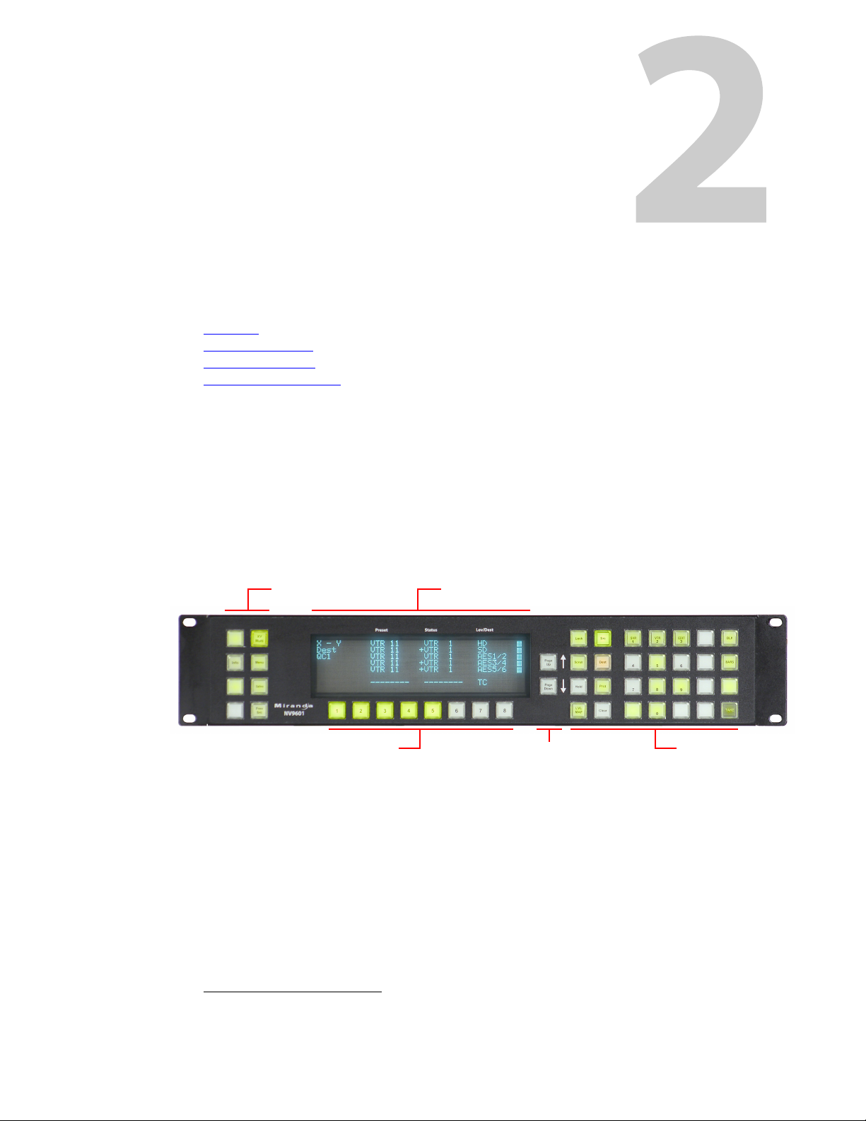
Summary
Scroll Buttons (2)
Function Buttons Selection Buttons
Alphanumeric DisplayFunction Buttons (8)
Introduction
Chapter 2 provides a functional description of the NV9601.
Topics
Summary . . . . . . . . . . . . . . . . . . . . . . . . . . . . . . . . . . . . . . . . . . . . . . . . . . . . . . . . . . . . . . . . . . . . . . . . . . . . . . . . . 3
Panel Organization
Modes of Operation
Other NV9601 Functions
The NV96011 is a 2RU control panel, 9.17” deep. The NV9601 has a large alphanumeric display,
36 function buttons, 8 selection buttons, and 2 scrolling buttons. The alphanumeric display has
8 lines of 42 characters. The 8 selection buttons correspond to the 8 lines of the display, the leftmost selection button corresponding to the top line and the rightmost button corresponding to
the bottom line. Operators select what is displayed on the particular line with the matching
button.
The panel is organized as shown in figures 2-1 and 2-2:
. . . . . . . . . . . . . . . . . . . . . . . . . . . . . . . . . . . . . . . . . . . . . . . . . . . . . . . . . . . . . . . . . . . . . . . . 4
. . . . . . . . . . . . . . . . . . . . . . . . . . . . . . . . . . . . . . . . . . . . . . . . . . . . . . . . . . . . . . . . . . . . . . . 7
. . . . . . . . . . . . . . . . . . . . . . . . . . . . . . . . . . . . . . . . . . . . . . . . . . . . . . . . . . . . . . . . . . . 8
Fig. 2-1: NV9601 Front View
The panels can operate in one of 2 modes:
• X-Y mode.
• Multi-destination mode.
The panels can be configured so that either mode is selectable by the operator. The panels can
also operate in several secondary modes, including salvo mode and menu mode.
1. An equivalent NV9601V — a GUI that is called a “virtual panel”— is available. It emulates the NV9601.
3
Page 14
Introduction
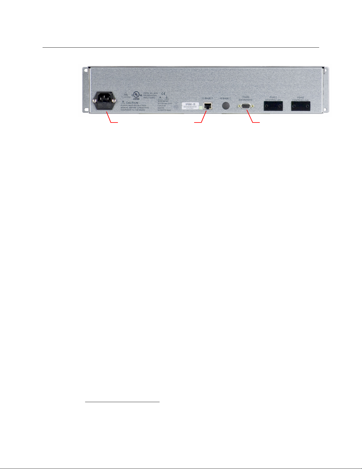
Ethernet (RJ- Serial port (RS-232)Power (AC)
Panel Organization
At the rear are power, serial, and network connectors:
Fig. 2-2: NV9601 Rear
The ports labeled 10base2 and RS-422 are non-operational and are covered. Only the serial port
and the Ethernet port are available.
The AC connector has a compartment in which you can find a spare fuse.
(The Ethernet port is 10baseT. The system controller supports 10baseT as well as 100baseT.)
Panel Organization
Function Buttons
The NV9601 has an array of 8 function buttons on the left and 28 function buttons on the right.
Function buttons either select sources and destinations or perform certain other functions such
as locking a destination or switching to the menu.
Each button has three operational levels: high and low tally (green or amber), and off. Operators
can adjust the illumination levels in increments of 10% using the panel’s menu. Buttons that are
turned off are said to be dark. (Their material is actually white or light gray.)
Generally, green represents a source or a source function and amber represents a destina-
tion or a destination function. However, amber and green can represent other functions too.
The function buttons each have clear plastic keycaps under which you may place plastic inserts
for button legends. It is a simple matter to change button legends.
1
Scroll Buttons
The NV9601 has 2 dedicated scroll buttons. These scroll the display up and down. A scroll button
is illuminated when scrolling is possible in that direction and dark when scrolling is not possible.
1. The NV9601V (virtual panel) has automatically generated button legends. For instance, a source button’s legend is the source name. Depending on the operating mode, the source button might have up
to 3 lines of text.
4
Page 15
NV9601
X Y HDX Y HD
Dest CAM1 SDDest CAM1 SD
VTR 1 CAM1 AUDIO 1VTR 1 CAM1 AUDIO 1
+CAM1 AUDIO 2 +CAM1 AUDIO 2
+CAM1 AUDIO 3 +CAM1 AUDIO 3
+CAM1 AUDIO 4 +CAM1 AUDIO 4
TIMECODE TIMECODE
Page 1Page 1
MultiDest CAM1 VTR1MultiDest CAM1 VTR1
CAM1 VTR2 CAM1 VTR2
CAM1 VTR3 CAM1 VTR3
CAM1 VTR4 CAM1 VTR4
CAM1 VTR5 CAM1 VTR5
CAM1 VTR6 CAM1 VTR6
CAM1 VTR7 CAM1 VTR7
Page 1 CAM1 VTR8Page 1 CAM1 VTR8
X-Y mode
Multi-destination mode
User’s Guide
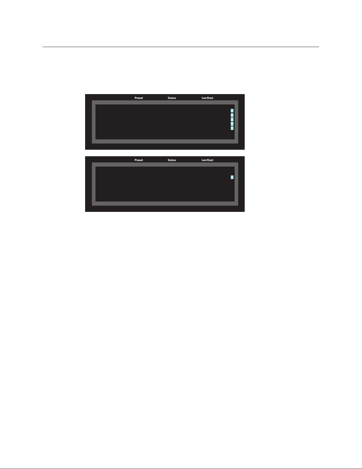
Alphanumeric Display
The 8×42 alphanumeric display provides real-time feedback for the operators as they press
buttons to execute takes and other operations. The panel functions in two modes: X-Y or multidestination. The display changes according to the mode:
In either case, the display has 8 lines. Operators might need to scroll the display to see additional
information. (The scroll buttons can be used to scroll the display.)
Display Fields
The display has 4 columns:
• Information (not labeled).
The first entry in this column is “X - Y” or ‘MultiDest” unless you have entered salvo mode,
menu mode, or setup mode. See chapter 5 for those topics.
The bottom-most entry in this column is always the page number of the display.
In X-Y mode, the second entry is always the word “Dest” as a title for the third entry which
identifies the current destination. In the preceding illustration, the current destination was
VTR 1.
In MD mode, there are no entries in this column other than “MultiDest” and the page number.
• Lev/Dest.
In X-Y mode, this column identifies the levels of the currently selected destination. That destination is identified in the information column. In the illustration above, ‘VTR 1’ was
selected. Operators might need to scroll to see or select a level.
In MD mode, the ‘Level/Dest’ column presents all the MD destinations defined in the
NV9601 configuration. (Actual destinations are defined in the NV9000 configuration.) Operators might need to scroll to see or select a destination.
• Status.
The status column indicates what source was routed to the destination.
5
Page 16

Introduction
Panel Organization
In X-Y mode, the status column represents the levels of a source or the levels of multiple
sources under breakaway. These are called the current source(s). The presence of ‘--------’ in
the status or preset columns means that that particular level is not defined for the destination. Therefore, no source selection for that level is possible. The illustration above shows
that levels HD and ‘TimeCode’ are not defined for VTR 1.
In MD mode, the status column represents the sources routed to each of the destinations in
the ‘Level/Dest’ column. Again, these are the current sources.
• Preset.
The preset column indicates what source will be routed to a destination when the operator
presses the ‘Take’ button.
In X-Y mode, the preset column represents the levels of a source or the levels of multiple
sources under breakaway. These are called the preset source(s). After the take, they disappear
from the preset column and re-appear in the status column, reflecting that the preset
sources have now become current sources.
In MD mode, the preset column indicates the sources that will be routed to selected destinations in the ‘Level/Dest’ column. These are the preset source(s). After the take, they disappear
from the preset column and re-appear in the status column, reflecting that the preset
sources have now become current sources.
The display fields can show either names from a name set or system mnemonics for devices
depending on (1) the state of the ‘Name Set Toggle’ button (if the panel has one), (2) the default
name set (3) the existence of name sets in the NV9000 configuration. (An alias is a name defined
in a name set.)
Flags
The display also shows flags of different kinds next to the sources and destinations.
Selection Marks
At the far right of the display are marks (rectangles) that turn on to indicate selections.
In X-Y mode, the marks turn on to indicate that a level is selected. They are not visible otherwise.
(The operator makes level selections using the selection buttons below the display.)
In MD mode, a mark appears to the right of the currently selected destination (and of all the
currently selection destinations when the panel is in hold mode).
Other Signs
A plus sign (+) indicates that additional information is available. There is an ‘Info’ button that
operators may press to view the additional information.
In MD mode, an asterisk (*) directly after a source name indicates a breakaway on that destination. In X-Y mode, an asterisk (*) directly after the destination name indicates a breakaway on
that destination.
An ‘L’ indicates that a device has been locked. A ‘P’ indicates that a device has been protected.
NV9601 operators may lock, protect or release sources and destinations if the panel configuration allows it. It is important for operators to know that other operators may lock, protect, or
release sources and destinations.
6
Page 17

Selection Buttons
Beneath the display are 8 selection buttons. The buttons correspond to the lines of the display.
Each button selects the item on the corresponding line. The left button corresponds to line 1
(the top line). The rightmost button corresponds to line 8 (the bottom line).
Selection buttons can be used in any mode.
Modes of Operation
The panel operates in either X-Y mode or multi-destination (MD) mode. A single button (XY/MD)
can toggle between the modes. A third mode
“button-per-source” mode
The primary modes of operation are:
• X-Y mode — individual control of all router levels. Choose a destination, optionally choose
desired breakaway levels, choose a source, and press ‘Take’ to complete a desired route.
• Multi-destination mode — lets you control multiple destinations. The display shows destina-
tions and their sources. You can scroll through destination lists using the ‘Page Up’ and ‘Page
Down’ buttons. Select a destination using selection buttons, choose a source, and repeat for
all desired routes. Then press ‘Take’. Takes are “all level,” and breakaways cannot be performed.
A ‘Hold’ button allows you to select many MD destinations at once.
The secondary modes of panel operation are:
• Setup mode — where the NV9601 is freshly powered up, but disconnected from the panel
network. In this mode, you can preset the NV9601’s panel ID and perform a few diagnostic
tasks.
• Salvo mode — the operator presses a Salvo button to enter salvo mode where the display
lists both system salvos and local salvos. The operator may select a salvo and then the ‘Take’
button to execute a salvo. (The duration of a salvo is indeterminate.)
• Menu mode — pressing a Menu button places the NV9601 in “menu” mode. In menu mode,
the display shows a menu that changes as needed during menu operation. Operators pick
menu items using selection buttons.
• Information mode — pressing an ‘Information’ button (when there is information to display)
places the NV9601 in “information” mode. In information mode, the display reports information such as level mappings.
Information is available, for example, when a plus sign appears next to a level in the
display under X-Y mode.
Other modes of operation are:
• Hold mode — when the operator presses the ‘Hold’ button, hold mode becomes active and
when the operator presses it again, hold mode becomes inactive. See Hold
• Save preset mode — when the operator presses the ‘Save Preset’ button, ‘Save Preset’ mode
becomes active and when the operator presses it again, ‘Save Preset’ mode becomes inactive. See Save Preset
• Scroll mode — when the operator presses a ‘Scroll’ button, scroll mode becomes active and
the operator may scroll through lists of devices for a category (during category device selection). Note that scroll mode does not cause the display to scroll.
NV9601
User’s Guide
— called “single-bus,” “single-destination,” or
— can be emulated in either X-Y mode or MD mode.
on page 42.
on page 47.
7
Page 18

Introduction
Other NV9601 Functions
Other NV9601 Functions
The NV9601 can be configured to perform the following additional functions:
• Previous source, free source, and source/destination buttons.
• Return to a pre-defined (or default) state.
• Hold breakaway levels.
• System salvos and local salvos.
• Lock/protect/release for destinations.
• Forced release of locked or protected devices.
• Device selection using category indexes or suffixes.
The NV9601 provides the following additional features:
• The NV9601 supports multiple-level breakaways in X-Y mode. This lets you route multiple
sources to the same destination on different levels.
• The panel supports gang or dub switching in multi-destination mode.
• Broadcast data routing in X-Y mode.
• Level mapping.
8
Page 19

Chapter 3 provides installation and connection instructions.
Topics
Package Contents . . . . . . . . . . . . . . . . . . . . . . . . . . . . . . . . . . . . . . . . . . . . . . . . . . . . . . . . . . . . . . . . . . . . . . . . . 9
Installation
Installing Software and Documentation
Initialization
Tes ti ng
. . . . . . . . . . . . . . . . . . . . . . . . . . . . . . . . . . . . . . . . . . . . . . . . . . . . . . . . . . . . . . . . . . . . . . . . . . . . . . . 10
. . . . . . . . . . . . . . . . . . . . . . . . . . . . . . . . . . . . . . . . . . . . . . . . . . . . . . . . . . . . . . . . . . . . . . . . . . . . . . . . . . . 11
Package Contents
If you have ordered one or more NV9601 control panels from Grass Valley, inspect the shipping
container for damage. If you find any container damage, unpack and inspect the contents. If the
contents are damaged, notify the carrier immediately.
As you unpack the shipping container, look for the packing slip and compare it against the
contents to verify that you received everything as ordered. If anything is missing (or if you find
equipment damage unrelated to shipping), please contact technical support. Refer to Grass
Valley Technical Support on page 73.
Depending on your order, the NV9601 items that can ship include:
• One or more NV9601 control panels.
• An AC power cord.
The package does not contain network cables, serial cables, or mounting screws.
You do not need to take any special precautions regarding ESD.
This document does not address the shipment or installation of any other equipment or software that can be used in conjunction with the NV9601 (including any system controllers, other
NV96xx control panels, EC9700 GUI, EC9710 GUI, and configuration programs such as UniConfig,
MRC, or NV9000-SE Utilities).
This document does briefly address the use of NV9000-SE Utilities and the Panel IP Configuration Utility as they pertain to panel configuration.
Installation
. . . . . . . . . . . . . . . . . . . . . . . . . . . . . . . . . . . . . . . . . . . . . . . . . . 10
. . . . . . . . . . . . . . . . . . . . . . . . . . . . . . . . . . . . . . . . . . . . . . . . . . . . . . . . . . . . . . . . . . . . . . . . . . . . . . 10
9
Page 20
Installation
ACQ IP
0
Firmware Menu Panel ID
Software
Test
Exit
Installation
Installation
Follow these steps to install a NV9601 control panel:
1 Mount, and secure, the panel in the rack.
The NV9601 is designed to mount in a standard 19” rack. Rack-mounting is not a requirement.
2 We assume that you have an Ethernet switch connected to the “Panel and Router Network”
port of your system controller. Connect an Ethernet cable from that switch to the RJ-45 port
at the rear of the NV9601.
3 Connect power.
Installing Software and Documentation
This document is available through the Grass Valley web site.
You must use NV9000-SE Utilities to configure the NV9601 control panel. Contact Grass Valley if
you need to obtain the latest version of this NV9000 configuration software.
You may use the Panel IP Configuration Utility if you want to your NV9601 to have a static IP
address or to use DHCP. The panel, as it comes from the factory, defaults to DHCP.
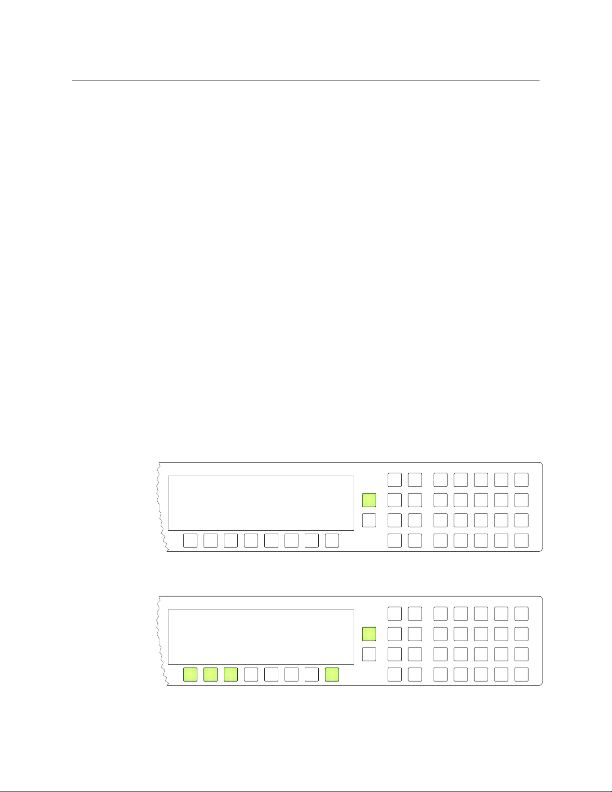
Initialization
Before your system controller can communicate with an NV9601, you must give it a panel ID.
Follow these steps for each NV9601 you are installing:
1 Power up the NV9601. Do not connect its Ethernet cable. (Disconnect it if it is connected.)
2 The ‘Firmware Menu’ appears.
After a few seconds, the alphanumeric display will show ‘ACQ IP’ at the top and show the
panel’s current panel ID. The ‘Page Up’ button illuminates:
Press the ‘Page Up’ button to proceed.
10
Page 21
NV9601
Firmware Menu
Panel ID Panel ID 0
Use Keypad to Change ID
6011
Cancel
Save
123
456
789
0
User’s Guide
In this menu, you have 3 options:
• Set the panel ID.
• View the software versions.
• Perform a panel test.
Some of the selection buttons are illuminated. To select an option, press the corresponding
selection button. To set the panel ID, press the leftmost selection button.
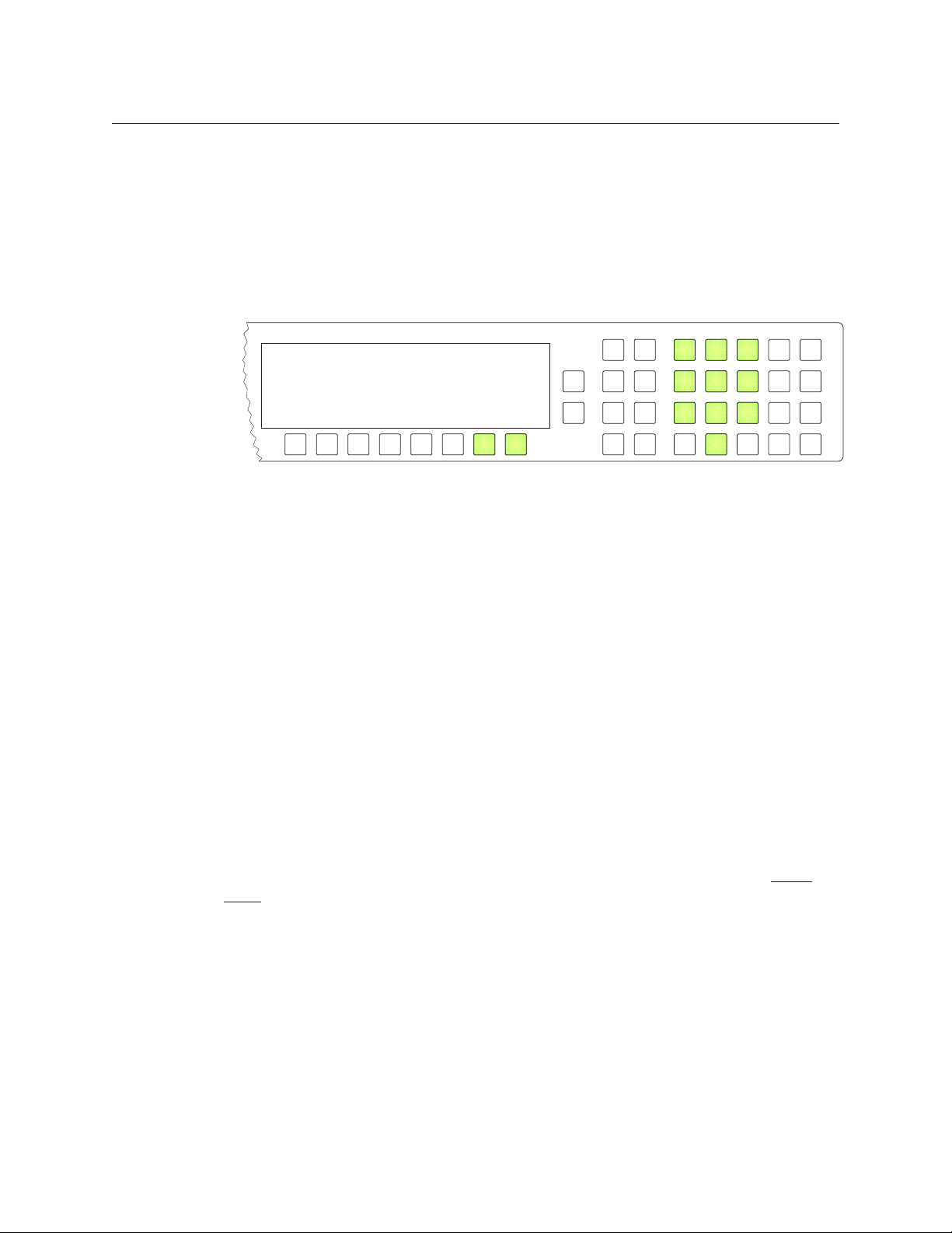
3 The ‘Panel ID’ menu appears and the “keypad” is activated:
The “keypad” is an array of function buttons, numbered in this illustration, that you can use
to enter the panel ID. Press the button numbered ‘1’ to enter the digit 1, and so on. Your new
panel ID appears on the display where the dashes are.
You can press selection button 7 to cancel your entry. The panel’s ID will remain unchanged.
Press selection button 8 to save your new entry. You can change it later at any time.
When you cancel, the display returns to the firmware menu. Press the selection button corresponding to ‘Exit’ to return to the initial display (that reads ‘ACQ IP’).
When you save, the display returns to the initial display.
4 After you designate the panel ID, reconnect the Ethernet cable. The system controller will
detect your panel in a few seconds. (All panel IDs must be unique.)
You can now prepare an NV9601 configuration in NV9000-SE Utilities and upload the configuration to the NV9601. You need the panel ID to create a NV9601 configuration. When you upload
the configuration, the panel ID you entered in NV9000-SE Utilities designates the actual panel to
which the upload will occur. If no actual panel has that ID, the upload cannot occur.
Testing
As shown above in step 2, a panel test function is available when the NV9601 is disconnected
from the system controller. Run the test to determine the health of your NV9601. See Setup
Mode on page 56 for detail. Press the selection button for ‘Software’ to review the versions of
installed software and firmware.
These are points to consider after you install your NV9601 control panel(s):
1 When the NV9601 powers up and it is connected to the system controller, it should initialize
completely. (That takes several seconds.) The NV9000 system should access whatever configuration exists for that panel and the buttons appropriate for that configuration should
light in the colors appropriate for the initial state of the panel.
If you continue to see “ACQ SVR” on the display, you have a problem. Reboot everything and
try again.
11
Page 22

Installation
Testing
The NV9601, by default, acquires its IP address through DHCP on the system controller’s
panel/router network. You can use the Panel IP Configuration Utility to force the panel to
have a static IP address.
If (in setup mode) you do not see your designated panel ID on the display, you have not initialized the panel.
2 Is the system controller actually running? With the typical noise levels in a facility, it can
sometimes be difficult to tell. Use the ‘System’ pages of NV9000-SE Utilities to make the
determination. You can determine whether the system has detected your panel by reviewing the control panels page for your particular system controller.
3 Does the configuration actually work? Is it useful? Can the operator perform takes and per-
form other operations?
The design of an NV9601 “operator interface” is non-trivial. You might want to consider how
well your operator interface works in addition to the basic question of whether it works.
12
Page 23

Summary
Configuration
Chapter 4 provides configuration instructions for the NV9601.
Topics
Summary . . . . . . . . . . . . . . . . . . . . . . . . . . . . . . . . . . . . . . . . . . . . . . . . . . . . . . . . . . . . . . . . . . . . . . . . . . . . . . . . 13
Adding a Panel to an NV9000 Configuration
NV9601 Panel Configuration Page
Commitment Buttons
Panel Options
Button Definitions
Selection Buttons
Multi-Destination Configuration
Salvo Configuration
Single-Destination Mode
This chapter addresses configurers. Operators and other persons not interested in NV9601
configuration need not read this chapter.
. . . . . . . . . . . . . . . . . . . . . . . . . . . . . . . . . . . . . . . . . . . . . . . . . . . . . . . . . . . . . . . . . . . . . . . . . . . . 18
. . . . . . . . . . . . . . . . . . . . . . . . . . . . . . . . . . . . . . . . . . . . . . . . . . . . . . . . . . . . . . . . . . . . 17
. . . . . . . . . . . . . . . . . . . . . . . . . . . . . . . . . . . . . . . . . . . . . . . . . . . . . . . . . . . . . . . . . . . . . . . . 22
. . . . . . . . . . . . . . . . . . . . . . . . . . . . . . . . . . . . . . . . . . . . . . . . . . . . . . . . . . . . . . . . . . . . . . . . . 27
. . . . . . . . . . . . . . . . . . . . . . . . . . . . . . . . . . . . . . . . . . . . . . . . . . . . . . . . . . . . . . . . . . . . . . 30
. . . . . . . . . . . . . . . . . . . . . . . . . . . . . . . . . . . . . . . . . . . . . . . . . . . . . . . . . . . . . . . . . 32
. . . . . . . . . . . . . . . . . . . . . . . . . . . . . . . . . . . . . . . . . . . . . . . . . . . . . . . . 16
. . . . . . . . . . . . . . . . . . . . . . . . . . . . . . . . . . . . . . . . . . . . . . . . . . . . . . . . . . 28
. . . . . . . . . . . . . . . . . . . . . . . . . . . . . . . . . . . . . . . . . . . . . . 13
The NV9601 has a relatively simple interface: a scrollable display and 36 function buttons. Each
of its buttons (green or amber, low- or high-tally) can either execute a function or select a source
or a destination.
The 8×42 alphanumeric display presents the status of operations as they occur. Under the
display are 8 selection buttons that correspond to the 8 lines of the display. Pressing a selection
button selects (or deselects) the item in the corresponding line of the display.
NV9000-SE Utilities is the software with which to configure the NV9601. Figure 4-1, following,
shows the default NV9601 panel configuration page from NV9000-SE Utilities.
Adding a Panel to an NV9000 Configuration
You must create configurations for the NV9601 using NV9000-SE Utilities. We assume that you
are familiar enough with NV9000-SE Utilities that you can understand the following material. It
is not difficult material, but some of the concepts might not be familiar to everyone.
It takes only a few seconds to add a new panel configuration.
13
Page 24
Configuration
Adding a Panel to an NV9000 Configuration
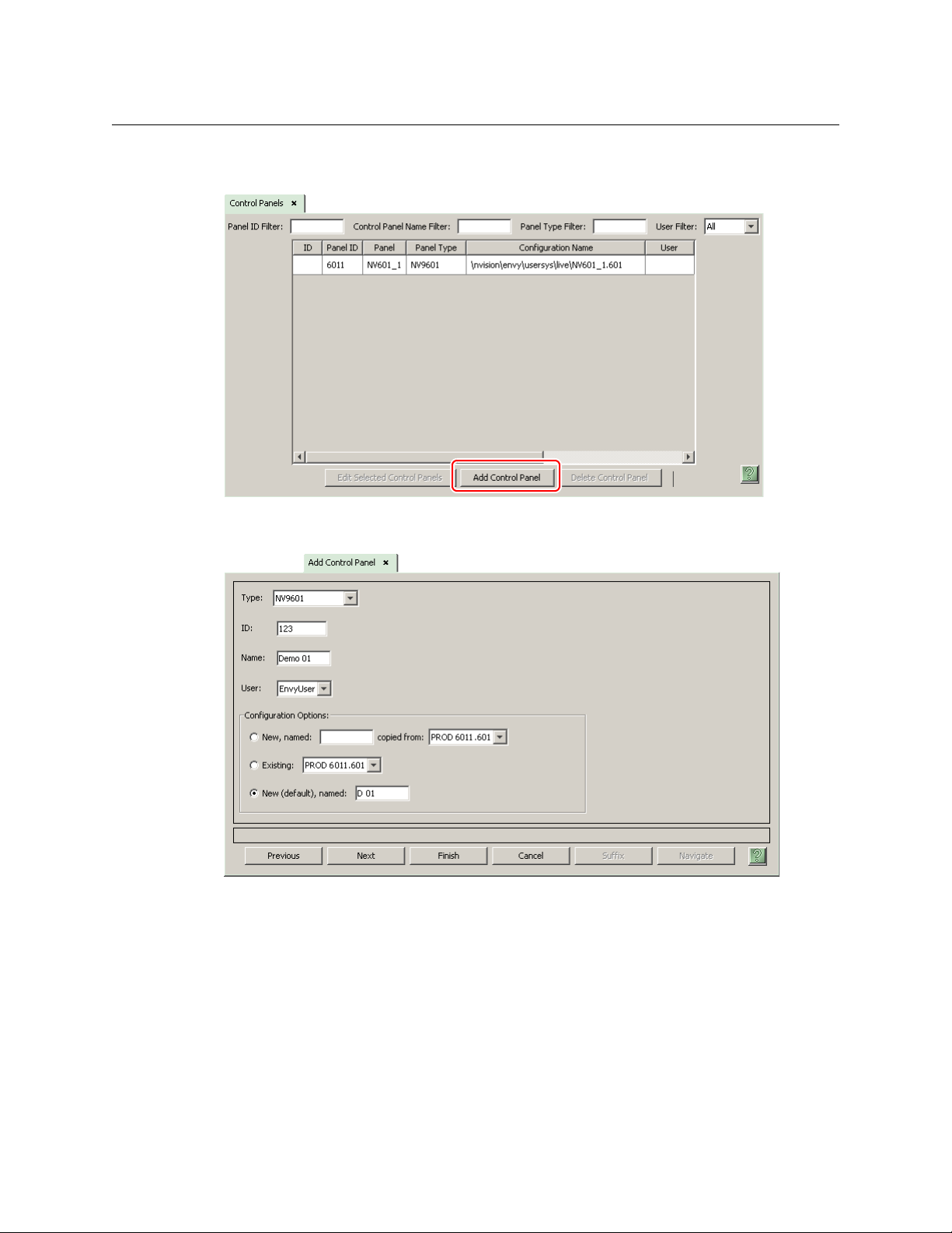
After launching NV9000-SE Utilities, choose ‘Control Panels’ from the Configuration pane in the
navigation area. The ‘Control Panels’ configuration page appears:
Click ‘Add Control Panel’ at the bottom of the configuration page. The ‘Add Control Panel’ page
appears:
14
Choose “NV9601” from the ‘Type’ field. In the ID field, enter the panel ID you assigned to the
panel while it was in setup mode. Give a name to the panel in the name field and select a user.
When you are creating a panel configuration you have 3 options. These options are presented in
the ‘Configuration Options’ area:
1 Make a copy of an existing configuration file, giving it a new file name.
2 Use an existing configuration file. (This allows several panels to share a single configuration.)
3 Create an entirely new configuration file.
In the first and third cases, you will create a new configuration file whose name you designate.
The file extension for an NV9601 configuration file is
.601. Click ‘Next’ or ‘Finish’ to proceed.
Page 25
NV9601
User’s Guide
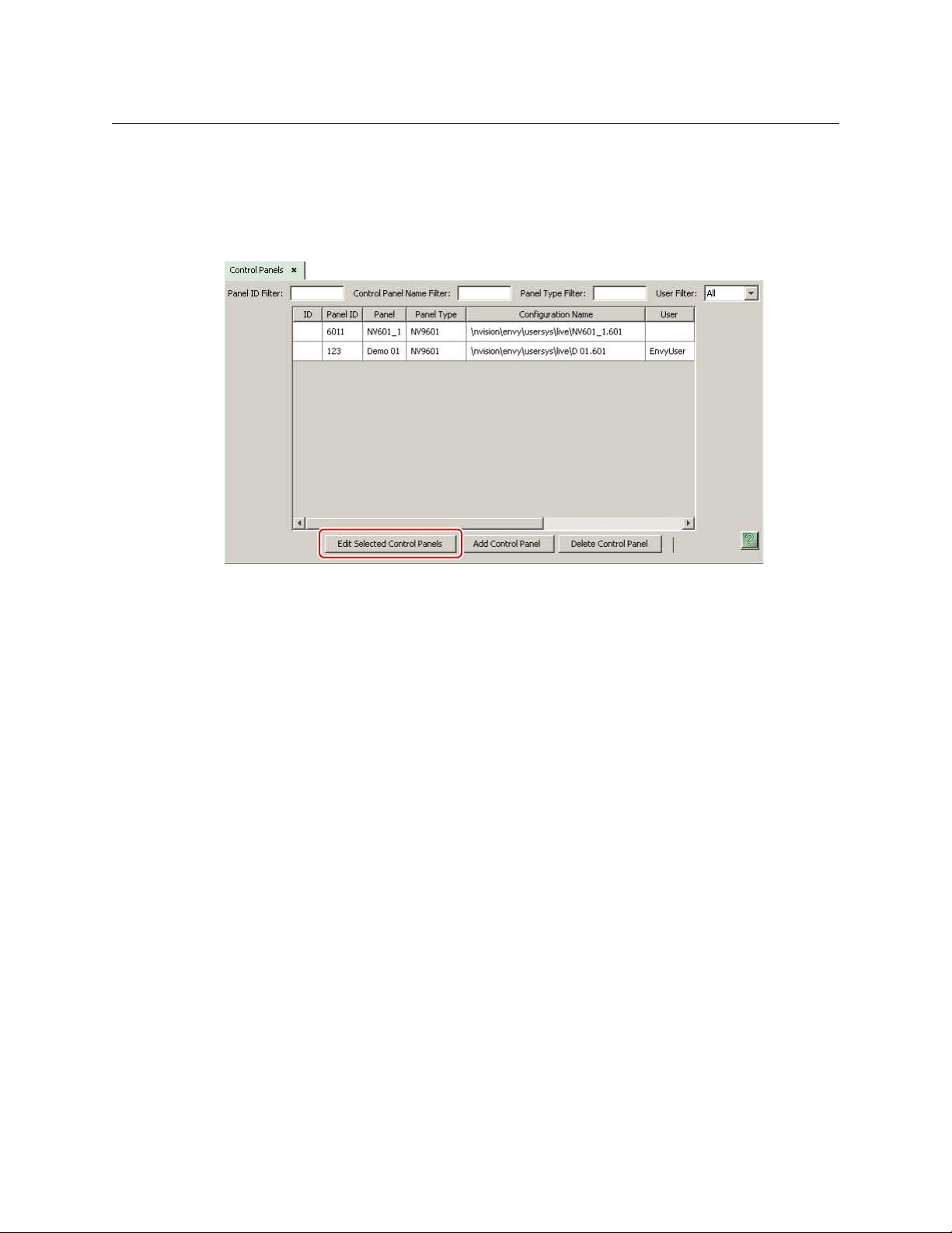
There are 2 other buttons, ‘Suffix’ and ‘Navigate’, both dim (disabled). These do not apply to
the NV9601.
Return to the ‘Control Panels’ page to view your new entry. To edit an NV9601 configuration,
either double-click its list entry or select the entry with a check in the checkbox and then click
‘Edit Selected Control Panels’:
You will then see the panel configuration page for the selected NV9601.
The following section of this guide discusses using the panel configuration page in which you
configure an NV9601.
15
Page 26
Configuration
Button
Definition
Section
Panel
Options
Panel Image
Category
(Keypad)
NV9601 Panel Configuration Page
NV9601 Panel Configuration Page
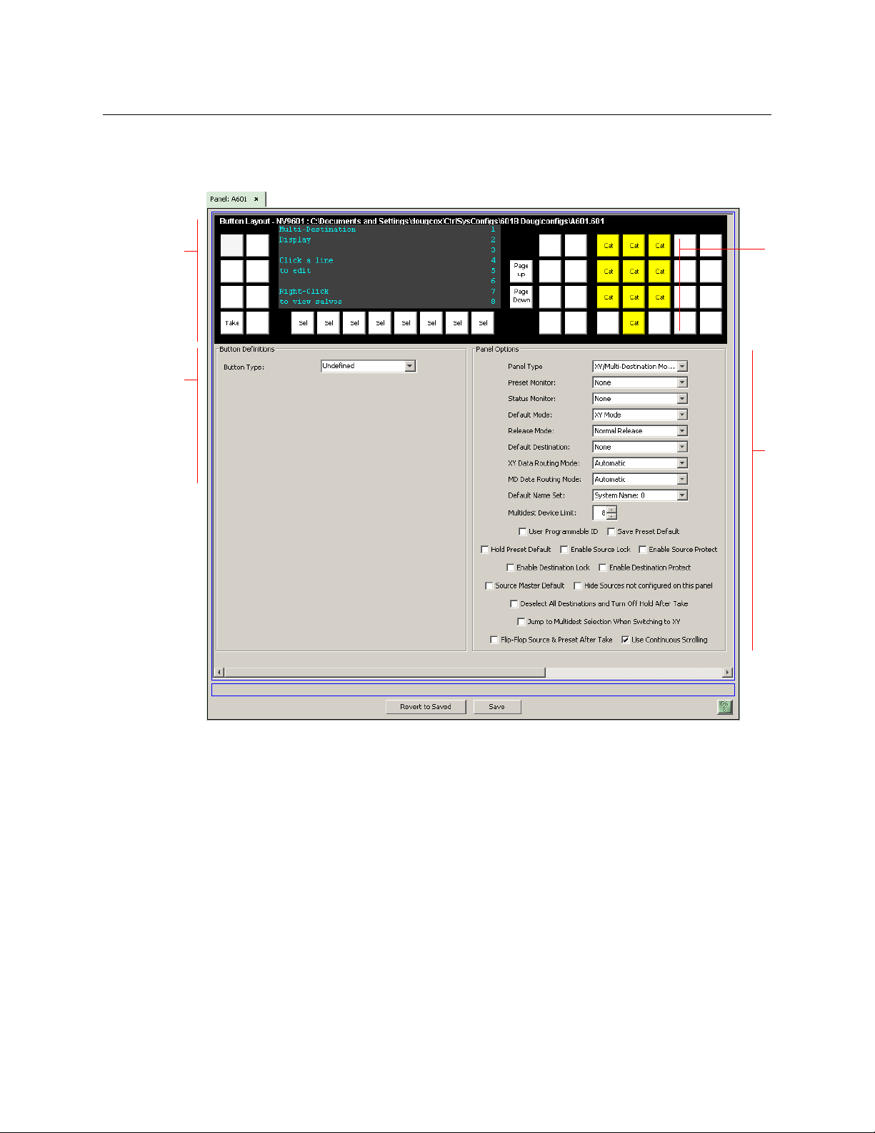
This is the default NV9601 panel configuration page in NV9000-SE Utilities:
Fig. 4-1: NV9601 Configuration Page (Default)
After you have configure the panel’s buttons, and the panel options, the page will have
changed.
At the bottom of the page are two important configuration buttons: ‘Revert to Saved’ and ‘Save’.
The ‘Save’ button commits modifications you have just made. The ‘Revert to Saved’ button
restores the last saved version of the panel configuration, canceling any changes you just made.
Regions of the Configuration Page
Above the ‘Revert to Saved’ and ‘Save’ buttons (always present) there are 3 main regions:
• A graphic representation of the NV9601 panel.
Click on any of the 36 button “proxies” to assign a function to that button. Specify the button
characteristics in the button definition section of the page.
In the middle of the graphic is a representation of the panel’s display. This representation
supports the definition of multi-destination devices and salvos. Click the display representa-
16
Page 27

NV9601
User’s Guide
tion to edit the multi-destination device list. Right-click the display to edit the panel’s salvo
list. Click the ‘Page Up’ or ‘Page Down’ button to scroll the display representation.
When you are editing the salvo list, right-click the display to return to the multi-destination
device list. When you are editing the salvo list, you can add or remove (1) system salvos and
(2) local salvos.
Click a line in the display to add or remove a system salvo. Control-click a line in the display
to add, remove, or rename a local salvo. See Salvo Configuration
Among the function buttons at the far right of the graphic are 10 buttons colored yellow.
These are category buttons. They can also be considered a keypad. (In fact, these buttons are
used for the keypad under setup mode and menu mode.) They cannot be configured as
other than category buttons. See Category Selection
The selection buttons (under the display) cannot be configured.
Buttons disabled during operation are dark on the control panel. Undefined buttons are
also dark.
on page 38.
on page 30 for more detail.
• Button definition section.
In this section, configurers make button assignments, using its pull-down menus and text
fields.
See Button Definitions
, following.
• Panel options.
In this section, configurers may specify the behavioral characteristics of the panel.
Configuration Tasks
The person configuring an NV9601 panel will want to consider how best to utilize the fixed
number of function buttons to support the devices and routers in the router control system at
hand. The task is non-trivial.
In support of that effort, the configurer will do the following:
• Select panel options.
• Assign functions to buttons.
The panel operator, in most cases, needs a ‘Take’ button. In addition to their basic function,
selection buttons provide feedback about the preset source device and level mapping. A ‘Clear
Preset’ button is strongly recommended.
Commitment Buttons
Two buttons at the bottom of the configuration page are self-explanatory and present on most
configuration pages:
• Revert to Saved. Press this button if you want to discard any recent changes you have made.
• Save. Press this button to commit all your recent changes.
Neither of these actions is reversible.
17
Page 28
Configuration
Panel Options
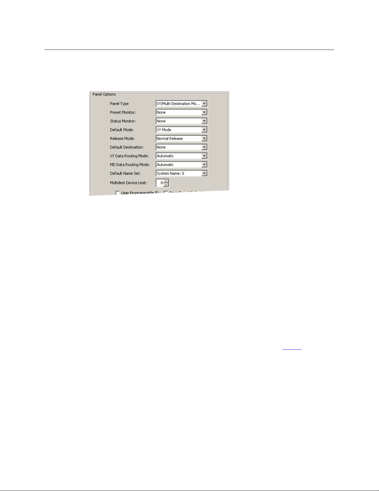
Panel Options
The panel options section, at the right of the configuration page, has two parts: drop-down
menus and checkbox options. These are the drop-down menus:
The minimum number of destinations for multi-destination mode is 8. If you have the minimum,
there is no need for scrolling during configuration. You may leave some (or all) MD destinations
undefined. Scrolling is disabled unless you have chosen more than 8 destinations as the multidestination device limit.
These are its drop-down menu options:
Panel Type XY / Multidest
Modes
Multidest Only Locks the panel in multidest mode. XY mode cannot be accessed.
XY Only Locks panel in XY mode. Multidest mode cannot be accessed.
Preset Monitor None The preset source video is not sent to a monitor.
‹device› The preset source video for the selected destination appears on
Status Monitor None The current source video is not sent to a monitor.
‹device› The current source video for the selected destination appears on
Default Mode X-Y Mode Starts the panel in XY mode after a reset. See Defaults
Multi-Dest Mode Starts the panel in multi-destination mode after a reset.
Release Mode Normal Release This panel can release “locks” and “protects” set by the designated
Force Release This panel can release locks and protects set by any user.
Default
Destination
None After a reset, the panel displays no destination device. (This is not
‹device› The Panel uses the specified device as the destination after a reset.
Panel can be used in either XY or multidest modes. If this option is
chosen, place an XY/MD button on the panel.
the specified monitor (device).
the specified monitor (device).
on page 60.
user (at this panel or any other panel).
recommended.)
(The ‘Default State’ button also returns the panel to this destination.)
18
Page 29

NV9601
User’s Guide
XY Data
Routing Mode
MD Data
Routing Mode
Automatic If a machine control (i.e., data) level is involved in a route, the sys-
tem makes the route on the control level even if the control port is
in use on the source or destination device. It breaks the previous
control connection and then makes a new control connection for
the route in progress.
Semi-automatic
(recommended)
Manual If the control port is in use for the source or destination device, the
Automatic If a machine control (i.e., data) level is involved in a route, the sys-
Manual If the control port is in use for the source or destination device, the
If the control port is in use for the source or destination device, the
system takes all (selected) levels except control and allows the
operator to perform the control level route by pressing ‘Take’ a second time. The operator may cancel the control-level take by pressing a button other than ‘Take.’
If the control port is not in use, the control level take occurs normally.
system takes all (selected) levels except control. It does not perform the control level route.
If the control port is not in use, the control level take occurs normally.
To carry out a take on a machine control port that is in use, the
operator must first free the port by performing a “tristate” take on
the port, that is, taking the device (as a source) to itself (as a destination) on the control level.
A take can occur on the machine control level if, in the status column of the display, the source entry is “FREE.”
tem makes the route on the control level even if the control port is
in use on the source or destination device. It breaks the previous
control connection and then makes a new control connection for
the route in progress.
system takes all (selected) levels except control. It does not perform the control level route.
If the control port is not in use, the control level take occurs normally.
To carry out a take on a machine control port that is in use, the
operator must first free the port by performing a “tristate” take on
the port, that is, taking the device (as a source) to itself (as a destination) on the control level.
An operator can determine whether the control level is free by
switching momentarily to X-Y mode and examining the destination’s levels.
19
Page 30

Configuration
Panel Options
Default Name
Set
Multidest
Device Limit
System Name A list of “name sets” appears in the drop-down menu. The name
sets can be defined under the System Management pane of
NV9000-SE Utilities. Choose ‘System Name’ in this list if you do not
want, or do not care about, device name aliases. Do not choose
‘System Name’ if you are configuring any ‘Name Set Toggle’ buttons.
(Selectable in
multiples of 8)
The number of multi-destination entries you are defining. (Strictly
speaking, this is not a limit, but a count.) The default, and lowest
value, is 8. The maximum is 512. (If you have more entries than
devices, you can leave some MD destinations unassigned.)
(If the configuration has 8 MD destinations, MD scrolling is disabled.)
Checkbox Options
The checkbox options section is at the bottom of the panel options section:
A check in the box enables the option. Clearing the checkbox disables the option.
By default, all the check box options are clear except ‘Use Continuous Scrolling’. That particular
option is enabled by default.
The following items are the checkbox options:
• User-Programmable ID.
Allows the Panel ID to be changed locally at the control panel (in menu mode).
• Save Preset Default.
Makes ‘Save Preset’ mode active when the panel reverts to its default state (after a Default
State button is pressed, or when the panel is restarted).
A ‘Save Preset’ button is needed only when you want the operator to be able to view or
change the mode.
• Hold Preset Default.
Makes “hold” mode active when the panel reverts to its default state (after a Default State
button is pressed, or when the panel is restarted).
Note: a ‘Hold’ button is needed only when you want the operator to be able to view or
change the mode.
• Enable Source Lock.
Check ‘Enable Source Lock’ to allow the panel operator to lock sources.
20
Page 31

NV9601
User’s Guide
• Enable Source Protect.
Check ‘Enable Source Protect’ to allow the panel operator to protect sources.
• Enable Destination Lock.
Check ‘Enable Destination Lock’ to allow the panel operator to lock destinations.
• Enable Destination Protect.
Check ‘Enable Destination Protect’ to allow the panel operator to protect destinations.
• Source Master Default.
Makes a control-level source the controlling device (or master device) by default. Otherwise,
the destination is the master by default. (The option is specifically for use with NVISION
series machine control routers.)
“Source is master” is used for duplication, or broadcast routing, on a machine control level.
“Destination is master” is for machine-to-machine editing. If you do not select the “source
master default” option, you can place a ‘Source is Master’ button on the panel.
Note: a ‘Source is Master’ button is a toggle that reverses the direction of data routing
for devices used in data level (machine control) takes.
• Hide sources not configured on this panel.
Causes the names of source devices that are not presently configured for this particular
panel to be effectively hidden. When another panel changes the source to one not configured for this panel, this panel displays asterisks instead.
• Deselect all destinations and turn off hold after take.
After selecting many MD destinations (with ‘Hold’ mode on), it can be time-consuming and
error-prone to find them all (and no others) to deselect them after a take. When you enable
this option, the NV9601 does exactly that (and turns off hold mode).
• Jump to multi-dest selection when switching to XY.
Makes the currently selected multi-destination device the current destination when you
switch from MD mode to X-Y mode.
The X-Y destination shown will be the default destination when the panel is in MD “hold”
mode and multiple destinations are selected
— if a default destination is specified in the
configuration. Otherwise, no destination will be selected.
• Flip-flop source and preset after take.
Swaps the preset source and the currently routed source for this destination after a take.
• Use continuous scrolling.
If you check this box, the panel scrolls MD destinations continuously. That is, the MD destination pages wrap around at the beginning and at the end of the page list.
If you uncheck this box, the panel will stop scrolling when it reaches either the beginning or
end of the MD device list.
This option does not affect scrolling of salvos when the panel is in salvo mode or levels when
the panel is in X-Y mode.
21
Page 32

Configuration
Button Definitions
Button Definitions
There are 2 classes of button functions:
• Dedicated functions, such as ‘Default State’ or ‘Chop’.
• Variable functions, such as ‘Category’ or ‘Source’. With this type of button, additional selec-
tions are needed to complete the button configuration.
Note
Certain button fields contain a colon (:) and number after the data in the field. The
number is the record ID of the object in the NV9000 configuration database. The
record IDs can be ignored but might be of some use when the configurer is searching
for items in the configuration database.
Button Specification
The button definitions section has several controls:
When you choose a button type, additional drop-down menus can appear, depending on the
button type, allowing you to further specify the button’s behavior. Available options and selections vary from button type to button type. You will frequently see these options:
Button Type A drop-down menu where you may select a button type.
Level Set Filter A drop-down menu listing level sets. Choosing a level set here restricts the
list of categories or devices to those belonging to that level set.
22
Page 33

NV9601
User’s Guide
Button Types
These are the button types available for NV9601 configurations:
Type Descript ion
Broadcast On the data (control) level, the button enables a broadcast take to an additional
controlled device, after a broadcast route has been initiated with a “source is
master” control-level take to the first controlled device.
The button is useful in dubbing applications or when a backup (redundant)
device is in use. See Broadcast Routes
See also the Source Master
Category Displays a category’s device list.
When you assign a category button, 4 additional drop-down menus appear:
‘Level Set Filter’, ‘Source Category’, ‘Destination Category’, and ‘Suffix’.
The level set filter allows you to restrict the list of categories according to the
level set to which the categories’ devices belong. Choose one of the level set
names in the drop-down list.
Each category button can represent a source category, a destination category,
and a suffix. When the panel is in source mode, the category button will select its
source category. When the panel is in destination mode, the category button will
select its destination category.
After a category has been selected, the suffixes on the category buttons come
into play. All of the panel’s category buttons that provide suffixes activate when
a category has been selected.
To configure the button, choose a source category and a destination category.
You can choose ‘None’ for either.
Finally, and optionally, choose a suffix from the drop-down list for suffixes.
Generally, suffixes are the numerals 0–9, but they can also be alphanumeric and
up to 4 characters in length. (You can review the available suffixes in the
‘Suffixes’ table under ‘Views’ in NV9000-SE Utilities.)
button, following.
on page 49.
Chop When a chop function is supported by the router, the button is a toggle that
enables and disables rapid switching of the selected destination device between
the current source and the preset source. This chop function is used to test
system timing.
Clear Preset Erases preset entries, while leaving the panel in the same mode. We recommend
you use this button because it is a “safety” feature.
The clear preset button has the side effect of switching off ‘Save Preset’ mode.
Default State Returns the panel to its most recent power-up state. That is called the default
state.
Destination Selects a destination.
When you assign a destination button, a drop-down menu appears: ‘Destination
Device’. Choose a device from the list.
The ‘None’ entry is merely a placeholder. Do not choose ‘None’.
23
Page 34

Configuration
Button Definitions
Type Descript ion
Destination
Lock
Sets or removes a “lock” on the current destination device. The lock can be
removed only by the user that originally set the lock, or by a panel that has
“Force Release” enabled.
In MD mode, an “L” appears next to the destination in the display when it is
locked. In X-Y mode, an “L” appears next to selected levels in the display when
they are locked.
Destination
Mode
Places the panel in destination mode. In destination mode, category buttons
that do not represent destinations become momentarily disabled (dark) and the
remaining enabled category buttons select destinations.
Note that the function of ‘Lock’ and ‘Protect’ buttons depend on whether the
panel is in destination mode or source mode.
Destination
Protect
Sets or removes a “protect” on the current destination device. The protect can be
removed only by the user that originally set the protect, or by a panel that has
“Force Release” enabled.
Note: a protect prevents others from routing to a destination; a lock prevents
anyone
— even the user who issued the lock — from routing to the destination.
In MD mode, a “P” appears next to the destination in the display when it is
protected. In X-Y mode, a “P” appears next to selected levels in the display when
they are protected.
Free Source Defines a phantom device that can be used to release or “free” devices on the
data (control) level. A free source is also used with tielines to free the tieline for
others to use. The free source is configured in the Level Set Details page of
NV9000-SE Utilities.
Hold Toggles the panel in and out of “hold” mode. In multi-destination mode, hold
mode retains destination selections after a take. In X-Y mode, hold mode retains
breakaway levels after a take. (There are other effects. See Selection Buttons
on
page 27.)
Information The information button displays auxiliary information about level mapping and
perhaps other matters. The operator presses the information button once to see
the information and again to hide the information.
Level Map Cross-connects levels (in the same physical router). The function is typically used
to shuffle audio channels, for example, to connect AES1/2 to AES3/4.
The Level Map mode is cancelled when the next normal take is performed
involving the selected destinations.
24
Lock The button locks (or unlocks) a source when the panel is in source mode and
locks (or unlocks) a destination when the panel is in destination mode.
Menu This button puts the NV9601 panel in menu mode and displays a menu on the
LCD buttons that provides access to a variety of panel options. The button is
required if you want the user to have access to the menu.
By pressing certain LCD buttons, the user makes menu selections and may enter
data (such as panel ID) or change LCD brightness values. The LCD button text
varies greatly with context in menu mode. See Menu Mode
on page 52.
Page 35

NV9601
User’s Guide
Type Descript ion
Name Set
Togg le
The button toggles the panel between its default name set and the “system
name” set. One or the other becomes the active name set.
The button definition has no fields to configure.
If the default name set is the system name set, the button would be a no-op.
Therefore configurers should not create a ‘Name Set Toggle’ button if the default
name set is ‘System Names’.
The status, preset, or destination displays use the active name set
— either the
default name set or the system name set. However, that when the panel is
displaying name sets, and a device does not have a name in the name set, the
panel displays the system name.
Panel Lock Prevents accidental changes to the panel settings, especially router crosspoints.
When the panel is locked, the button array becomes blank except for the Panel
Lock button which becomes amber. Pressing the ‘Panel Lock’ button again
reverts the panel to its previous mode.
Preset
Release
Previous
Source
Removes locks and protects from preset source devices. This button is not
needed if source locks and protects are not used in your system.
Presets the previously routed source to the currently selected destination. The
operator must next press take to restore the previous source. This function is
useful when a user makes a route in error.
The button does not restore the previous destination. If the user changed the
destination and presses ‘Previous Source’, the take will not restore the previous
route.
Protect The button protects (or unprotects) a source when the panel is in source mode
and protects (or unprotects) a destination when the panel is in destination
mode.
Quick Source A quick source button selects a source and performs an immediate take.
When you assign a quick source button, a drop-down menu appears in which
you choose a source device.
The ‘None’ entry is merely a placeholder. Do not choose ‘None’.
Salvo The button puts the panel in salvo mode where the operator can choose a salvo
(local or system) to execute, review the contents of any salvo, and execute a salvo
(by pressing ‘Take’).
Save Preset When this function is enabled (its button is high tally), whatever is on preset is
retained (on preset) after a take. When the function is disabled (its button is low
tally), preset is cleared after a take.
Scroll A scroll button places the panel in scroll mode, where the operator can scroll
(using the ‘Page Up’ and ‘Page Down’ buttons, through devices belonging to a
category during category device selection.
If the panel is in scroll mode, the operator cannot specify a category’s device by
suffix. Note also that the button does not cause the display to scroll.
25
Page 36

Configuration
Button Definitions
Type Descript ion
Source A source button selects a source. (Note that a quick source button selects a
source and also performs an immediate take.)
When you assign a source button, a drop-down menu appears: ‘Source Device’.
Choose a device from the list.
The ‘None’ entry is merely a placeholder. Do not choose ‘None’.
Source
Master
Means “source is the master” and makes the source device the master. Otherwise, the destination is the master.
The button is a toggle: Press it once to make the source the master (it goes hightally); press it again to make the destination the master (the button is low-tally).
A panel option allows you to make “source is master” the default. In this case, the
button still toggles between “source is master” and “destination is master,” and
the button, if present, is high-tally by default.
The ‘Source is Master’ button is also used to initiate “broadcast” control routes.
See Broadcast Routes
on page 49.
Source/
Mode
Src/Dst
Mode
Take In X-Y mode, a take button switches the preset source device to the selected
Undefined Makes the button undefined and inactive. On the actual panel, it will remain
Virtual Level
Contract
Virtual Level
Expander
Places the panel in source mode. In source mode, category buttons that do not
represent source become momentarily disabled (dark) and the remaining
enabled category buttons select source.
Note that the function of ‘Lock’ and ‘Protect’ buttons depend on whether the
panel is in destination mode or source mode.
Toggles the panel between source mode and destination mode.
Note that the function of ‘Lock’ and ‘Protect’ buttons depend on whether the
panel is in destination mode or source mode.
destination device on selected levels.
In MD mode, a take button switches the preset source device(s) to the selected
destination device(s) on all levels.
In most cases, configurers should provide the operator a ‘Take’ button.
unlit (dark).
In X-Y mode, this button causes the alphanumeric display to show virtual levels
at the highest level of grouping (with the least detail). The button affects only
virtual levels that have been grouped. See Level Grouping
The button has no effect in multi-destination mode.
This button has no configuration options.
In X-Y mode, this button causes the alphanumeric display to show virtual levels
at the lowest level of grouping (with the most detail). The button affects only
virtual levels that have been grouped. See Level Grouping
The button has no effect in multi-destination mode.
This button has no configuration options.
on page 37.
on page 37.
26
XY/MD
Mode
Switches the panel between X-Y mode and multi-destination mode.
The button is always green for XY mode and amber for multi-destination mode.
Page 37

Selection Buttons
Selection buttons are dedicated buttons; they are not configurable. Each selects or deselects the
item on the corresponding line of the display. Button 1 (left) selects what is on line 1 (the top)
and so on.
Selection buttons support level selection in XY mode and device selection in multi-destination
mode. Operators can scroll through multiple pages of levels in X-Y mode and through multiple
pages of devices in MD mode. The operator makes selections from whatever appears on the
display at any given time.
Selection buttons also allow operators to select menus when the panel is in menu mode (or in
setup mode) and to select salvos when the panel is in salvo mode.
Selection (of either levels or MD devices) is affected by ‘Hold’ mode. (See the Hold
page 24.) The operator may toggle hold mode at any time. Using the selection buttons follows
hold mode or non-hold mode, whichever is in effect at the moment. Non-hold mode is the
default
— unless you specify otherwise in the Panel Options.
Selection Button Behavior
NV9601
User’s Guide
button,
XY Mode
When the panel is in XY mode, the selection buttons represent the virtual levels present in the
display. If there are fewer than 8 levels in the level set of the current destination device, the
rightmost selection buttons will be dark (disabled) and the bottom lines of the display will be
empty.
If a level is selected, the selection button is high-tally, and there is a rectangular marker at the
right end of the line in the display that shows the level. If a level is not selected, the selection
button is low-tally, and there is no marker for that level.
If the level does not exist for the currently selected destination, the matching selection button is
dark.
If there are more levels than selection buttons, the ‘Page Up’ and ‘Page Down’ buttons activate
and the operator can scroll through the levels.
The levels displayed might be level groups: The operator can use ‘Virtual Level Expand’ or
‘Virtual Level Contract’ buttons to expand or collapse the displayed level groups.
MD Mode
When the panel is in MD mode, the selection buttons represent the currently displayed MD
devices.
If an MD device was not defined, the line of the display is blank and the corresponding selection
button is dark. If an MD device is selected, its selection button is high-tally, and there is a marker
at the right end of the line showing the device. If an MD device is not selected, its selection
button is low-tally, and there is no marker for that device.
(Configurers perform MD destination population by clicking on the image of the display and
making entries in the MD device table that appears. See Multi-Destination Configuration
page 28.)
on
27
Page 38

Configuration
Multi-Destination Configuration
If there are more destinations than selection buttons, the operator can scroll through the destinations using ‘Page Up’ and ‘Page Down’ buttons.
Note that the maximum number of MD destinations is configured in multiples 8, from 8 to
512. Not all of those need be defined.
Selection
XY Mode — Normal
When the operator selects a destination, all selection buttons that have levels defined for the
current destination turn on (high-tally). The operator may select or deselect any levels as
required, by pressing selection buttons and perhaps scrolling the display.
Note that if the operator selects a level when all levels are on, all the other levels become
unselected (low-tally).
Selecting a new destination again turns on all selection buttons that have levels defined.
XY Mode — Hold Mode
In hold mode, when the operator selects a destination, previously selected levels (defined for
the destination) remain selected for additional takes and previously unselected levels remain
deselected. (Individual levels turn on or off as the user selects them.)
MD Mode — Normal
When the user selects an MD device, all selection buttons are mutually exclusive: when the
operator presses one button, any others that were selected turn off. To perform MD takes, the
operator alternately selects an MD device and then a source until all intended devices have
been preset. Then the operator presses ‘Take’.
MD Mode — Hold Mode
In hold mode, selection buttons are not mutually exclusive. To perform MD takes, the operator
selects one or more MD devices. The operator then selects a source (which becomes preset for
all the selected devices).
The operator can preset another source to another set of destinations by deselecting selected
destinations, selecting other destinations, and selecting another source.
When all intended destinations are preset, the operator then presses ‘Take’.
(In hold mode, selected MD devices remain selected after the take. In non-hold mode, any
selected MD devices become unselected after the take.)
Multi-Destination Configuration
Multi-destination (MD) devices are a subset of all destination devices that the operator may use
in the ways supported by MD mode. You can configure a panel to have from 8 to 512 MD destinations in increments of 8 destinations. Not all of those need be used. Those that are not used
are considered “undefined.”
It is possible to have duplicate entries in the MD destination set. For example, it might be
useful to have one or two MD destinations available at all times.
28
Page 39

NV9601
User’s Guide
Multi-destination configuration uses the display portion of the panel graphic in the panel
configuration page. It also uses ‘Page Up’ and ‘Page Down’ buttons
— also in the panel graphic
— to select a group of MD destinations that will appear in the display. The display scrolls by 8
lines when you click a scroll button.
The limit to the number of MD devices is controlled by a panel option. If the limit is 64, for
example, the display can scroll through 8 pages of 8 rows, regardless of whether these rows
have been assigned a destination device.
Initially the list of MD destinations is empty and all you will see in the display are numbered
blank lines. After you assign MD destinations to the numbered lines, the destinations’
mnemonics appears on those lines.
How to Configure MD Destinations
Follow these guidelines.
1 Click any line in the display portion of the panel graphic. (A single click is all that is required.)
A dialog appears. This is the multi-destination entry editor:
On the left is a list of all destinations defined in the NV9000 system. On the right is a table of
the MD destinations you are defining. The number of rows in this table is equal to the maximum number of MD destinations your configuration allows.
To define an MD destination, select a destination on the left and copy it, using either the
‘Append’ button, the ‘Insert’ button, or the ‘Replace’ button, to the right.
The ‘Append’ button appends the selected destination to the end of your set of MD destinations.
The ‘Insert’ button places the selected destination immediately above whatever MD destina-
tion you have highlighted on the right.
The ‘Replace’ button replaces whatever MD destination you have highlighted on the
right.with the selected destination from the left.
29
Page 40

Configuration
Salvo Configuration
The ‘Remove’ button removes highlighted MD destinations from the right.
At the bottom left, there is a scroll box in which you can adjust the maximum number of MD
destinations. (The page size is indicated as fixed at 8 entries. You cannot change the page
size.)
At the bottom right, are ‘Move Up’ and ‘Move Down’ buttons. You can use these to adjust the
position in the list of any MD destination.
After you have finished configuring MD destinations, click OK (or cancel, if you want to discard your entries). The MD destinations you have configured now appear in the display section of the panel graphic. They will subsequently appear in the display of the panel when it is
operating in MD mode.
You can edit the set of MD destinations later, adding or removing entries as you wish.
MD Destination Options
On the right side of the multi-destination entry editor, each MD destination has two checkboxes. One is in the ‘User Definable’ column and the other is in the ‘User Selectable’ column.
User-Definable
When the MD destination is “user definable,” the operator may choose a different destination
using the panel buttons. “User definable” is the default for all MD destinations. Uncheck the
‘User Definable’ box if you want to prevent the operator from changing this MD destination.
You can check or uncheck all the entries in this column by right-clicking the column heading.
User-Selectable
When the MD destination is “user selectable,” the operator may select it and take sources to it.
That is also the default for all MD destinations. Uncheck the ‘User Selectable’ box if you want to
prevent the operator from taking a source to this destination.
You can check or uncheck all the entries in this column by right-clicking the column heading.
You can also just to leave a destination out of the MD list if you do not want the operator to
use it.
Salvo Configuration
Salvos are stored command lists. The NV9000 system supports system salvos. Some control
panels, including the NV9601, also support local salvos. System salvos are defined in NV9000-SE
Utilities. Local salvos are named during NV9601 panel configuration and defined (or redefined)
by panel operators by recording actions performed at the panel. (Panel operators cannot
change the names of salvos.)
To configure salvos, right-click the display region of the panel graphic in the NV9601 configuration page to switch it to salvo configuration. (If you have already switched, do not right-click the
display.)
30
Page 41

NV9601
User’s Guide
The salvo configuration image appears:
To add or remove system salvos, click either a blank line or an existing system salvo. You might
need to scroll the display if there are many salvos defined.
To add, remove, or rename a local salvo, control-click either a blank line or an existing local salvo.
Clicking a local salvo has no effect. Control-clicking a system salvo likewise has no effect.
System Salvos
When you click a system salvo, the following dialog appears:
Select a system salvo from the drop-down menu. If the salvo was already in the salvo list, you
can delete it from the list.
Click OK to confirm your entry or ‘Cancel’ to cancel it.
Local Salvos
When you click a system salvo, the following dialog appears:
To create a local salvo, enter or re-enter the name of a local salvo in the text box.
If the local salvo exists already, you can delete it from the NV9601’s salvo list.
Click OK to confirm your entry or ‘Cancel’ to cancel it.
After you create a local salvo, it is empty. It contains no commands. It is the task of the panel
operator to create or erase the contents of a local salvo by recording actions at the panel. See
Salvo
on page 54 for information. (Local salvo definition is a function available when the panel is
in menu mode.)
31
Page 42

Configuration
Single-Destination Mode
Single-Destination Mode
Single-destination mode (a.k.a., “single-bus” or “button-per-source” mode) can be emulated in
either X-Y mode or MD mode.
Single-destination mode is not a distinct mode. It can be blended with either of the other two
modes. You can create many different forms of “single-destination” mode. This mode need not
have just one destination.
The simplest form presents a group of “source” buttons. If you configure a default destination in
the panel options, all the sources could be taken to a (single) default destination with no need
for destination selection.
Other more complex forms of “single-destination” mode are conceivable.
32
Page 43

Summary
Operation
Chapter 5 provides operating instructions for the NV9601 control panel.
Topics
Summary . . . . . . . . . . . . . . . . . . . . . . . . . . . . . . . . . . . . . . . . . . . . . . . . . . . . . . . . . . . . . . . . . . . . . . . . . . . . . . . . 33
Operating Concepts
Salvo Mode
Menu Mode
Setup Mode
This chapter is intended specifically for the NV9601 panel operator.
As an NV9601 operator, you will be confronted initially with a relatively simple panel — 36
buttons and a scrollable alphanumeric display. The design of the user interface is entirely at the
discretion of the configurer. You, the user, depend on the configurer having designed a useful
panel.
The user interface of an NV9601 in one installation can be radically different from the user interface of an NV9601 in another installation. It is impossible to describe operations in great detail
because there is no one interface. What we can do, however, is give you general advice and, of
course, specific information on the behavior of the different button types and operational
modes.
The panel’s buttons can have arbitrary legends (because they are inserts under the clear plastic
button caps). A button’s legend might or might not indicate its function. Operators and configurers will have to communicate about the meaning of the buttons.
The alphanumeric display (8 lines of 42 characters) shows the status of takes (pending or
complete) in X-Y mode or multi-destination mode under normal circumstances. The display
presents information or menu items as isolated cases warrant. You can scroll the display as
necessary.
Physically, you will find
• Function buttons (that, e.g., select a source or lock a destination).
• Selection buttons that select levels in X-Y mode and devices in MD mode.
• Status of preset and current sources and the selected destination(s).
At any particular time, some of the buttons are enabled or disabled. Some are high-tally; some
are low-tally; and some might be undefined.
Please refer to the NV9000-SE Utilities User’s Guide (or the NV9000-SE Utilities help files) if you
are unfamiliar with the concepts used in this chapter.
. . . . . . . . . . . . . . . . . . . . . . . . . . . . . . . . . . . . . . . . . . . . . . . . . . . . . . . . . . . . . . . . . . . . . . . . . . . . . . . 51
. . . . . . . . . . . . . . . . . . . . . . . . . . . . . . . . . . . . . . . . . . . . . . . . . . . . . . . . . . . . . . . . . . . . . . . . . . . . . . 52
. . . . . . . . . . . . . . . . . . . . . . . . . . . . . . . . . . . . . . . . . . . . . . . . . . . . . . . . . . . . . . . . . . . . . . . . . . . . . . 56
. . . . . . . . . . . . . . . . . . . . . . . . . . . . . . . . . . . . . . . . . . . . . . . . . . . . . . . . . . . . . . . . . . . . . . 36
33
Page 44

Operation
Summary
Modes of Operation
The panel operates primarily in either “X-Y mode” or a “multi-destination mode.” An XY/MD
button can toggle between the modes. (The configurer can specify the default mode.)
The primary modes of operation are:
• X-Y mode — individual control of router levels. Choose a destination, optionally choose
desired breakaway levels, choosing a source or sources, and press ‘Take’ to complete a
desired route. Sources are taken only on selected levels.
• Multi-destination (MD) mode — lets you view and control multiple destinations. The button
tree presents destination devices on selection buttons. You can scroll through the MD device
list using ‘Page Up’ and ‘Page Down’ buttons. Select one or more MD devices, choose a
source, and repeat for all desired routes. Then press ‘Take’. Takes are “all level,” and breakaways cannot be performed.
MD mode allows you to make multiple routes in a single take.
• Single-destination mode — A single destination is defined during configuration. You have
only to choose a source and press ‘Take.
Single-destination mode is not a distinct mode and actually need not involve only a single
destination. It can be combined with X-Y mode or multi-destination mode.
Secondary modes are:
• Setup mode — where the NV9601 is freshly powered up, but disconnected from the network.
In this mode, the configurer can preset the NV9601’s panel ID and perform a few diagnostic
tasks.
Usually, only configurers need be concerned with setup mode.
See Setup Mode
• Salvo mode — pressing a ‘Salvo’ button places the panel in salvo mode, where the salvos are
listed on the display. You can select a salvo and then press ‘Take’ to execute the salvo. The
duration of a salvo is indeterminate.
• Menu mode — pressing a ‘Menu’ button places the NV9601 in “menu” mode. In menu mode,
the LCD button array becomes a menu button panel that changes as needed during menu
operation. Some menu data are presented on the alphanumeric display.
There is nothing in the menu that concerns operators except LCD brightness. An operator
may use the menu to set LCD brightness. Administrators and configurers may use the menu
to view or change the panel ID, or to determine the software and firmware revisions.
See Menu Mode
• Information mode — pressing an ‘Information’ button (when there is information to display)
places the NV9601 in “information” mode. In information mode, the display reports information such as level mappings.
Information is available when a plus sign appears next to a level in the display under X-Y
mode.
Other modes are:
• Source mode — the panel is ready for you to select a source category or to lock or protect a
source.
• Destination mode — the panel is ready for you to select a destination category or to lock or
protect a destination.
on page 56.
on page 52.
34
Page 45

NV9601
MultiDest CAM1 VTR1MultiDest CAM1 VTR1
CAM4 CAM2 VTR2 CAM4 CAM2 VTR2
CAM5 CAM3 VTR3 CAM5 CAM3 VTR3
CAM4 VTR4 CAM4 VTR4
CAM5 VTR5 CAM5 VTR5
CAM6 VTR6 CAM6 VTR6
CAM7 VTR7 CAM7 VTR7
Page 1 CAM8 VTR8Page 1 CAM8 VTR8
User’s Guide
• Hold mode — in hold mode, level selections (under X-Y mode) persist from one take to
another and under MD mode, you can select multiple MD devices.
• Save preset mode — in “save preset” mode, whatever is on preset is retained (on preset) after
a take.
• Scroll mode — in scroll mode, you can scroll through a list of devices for a category (during
category device selection).
Button Legends
There are about 32 different button functions. Some might not be available on your panel. Typically, buttons have graphic or text legends that are plastic inserts placed under the clear button
caps.
There are button templates available. Use these or your own to create button graphics. Print the
graphics on clear plastic, cut the button graphics apart and insert these under the clear button
caps.
Buttons are also color-coded to a limited degree. Green represents sources. Amber represents
destinations. Those colors are used for other functions, however. High-tally (bright) buttons are
those that are selected; low-tally (dim) buttons are those that are not selected. Dark buttons are
those that are disabled. Dark buttons are unlit, and actually white or gray in color.
MD Devices
In multi-destination (MD) mode, MD devices appear in a list on the display and can be selected
with the selection buttons below the display. It is often necessary to scroll the display to be able
to select particular MD devices.
To perform an MD take, you assign sources to as many MD devices as you like and then press
‘Take’. The multiple takes occur (nearly) simultaneously.
To assign a source to an MD destination, select the destination using a selection button. You
might have to scroll the display to find the MD destination of interest. Then either locate and
press a source button or use the category buttons to perform category selection. (In hold mode,
you can assign a source to several MD destinations at once.)
In this example, the displays shows that two sources, CAM--4 and CAM--5, were preset to 2 destinations, VTR--2 and VTR--3, respectively:
35
Page 46

Operation
Operating Concepts
Lists
The NV9601 presents several items in lists: levels, MD devices, salvos, and category devices.
You can scroll through lists to view, and select, entries in the list.
Category device lists are different from other lists. The list itself does not appear on the display.
However, the display does show the device in the list you have presently chosen.
To scroll through category devices, a ‘Scroll’ button is required on your panel. Press a category
button, then press the ‘Scroll’ button to enable scrolling through devices, and then use the
‘Page Up’ and ‘Page Down’ buttons to advance to the previous or to the next device in the list.
The MD device list, the salvo list, and the level list do appear on the display. For MD devices,
salvos, and levels, it is sufficient just to press the ‘Page Up’ and ‘Page Down’ buttons to scroll. The
display scrolls in “pages” of 8 items at a time.
Operating Concepts
Status for most or all operations is presented on the alphanumeric display (and occasionally on
certain buttons).
Levels
In NV9000-SE Utilities and in the NV9000 router control system, routes occur on levels. A level is
typically SD, HD, analog video, AES, analog audio, or machine control. Various devices are
defined as sending and receiving signals on certain levels. The set of levels handled by a device
belong to what is called a level set.
A source can be routed to a destination if it has the same set of levels, i.e., it belongs to the same
named level set. A source can be routed to a destination in a different level set if the NV9000
configuration has the appropriate inter-level set mapping.
The effect of this is that when you, the operator, choose a destination, the NV9000 software
recognizes which source devices are allowed to be routed to the destination and limits your
selection to those sources.
Breakaway
Routes can be all-level in which case they are taken on all levels defined for the destination. The
acceptable sources for a route have the same levels as, or some configured mapping to, the
levels of the destination.
A breakaway is where you take different sources to the same destination
It is not possible to take different sources to the destination on the same level. For instance, you
cannot take SD from two different sources. The outcome would be noise even if you could do it.
(That is because routers are not mixers.)
— on different levels.
36
Level Mapping
If a level was level-mapped, the display shows a plus sign next to the level name.
See Level Map
on page 43 for usage information.
Page 47

NV9601
HD SD Aud1 Aud2 Aud3 Aud4 Aud5
Video Audio
. . .
User’s Guide
Virtual Level Expand and Contract
If the levels for a particular device belong to a virtual level group, you can collapse the display of
levels to its minimal possible representation (just the group names) or expand the display of the
levels so that all individual levels are displayed.
Use the ‘Virtual Levels Contract’ button to collapse the list of levels. Use the ‘Virtual Levels
Expand’ button to expand the list of levels.
See Level Grouping
, following.
Level Grouping
Virtual levels can be grouped. This diagram illustrates grouping:
There are two types of virtual levels: basic and abstract. Basic virtual levels are those that
correspond to actual physical levels. Abstract virtual levels do not correspond to physical levels.
In the illustration, the 5 “Aud x” levels are grouped under ‘Audio’. The two video levels are
grouped under ‘Video’.
The levels ‘Video’ and ‘Audio’ are abstract levels; the other levels are basic levels.
The NV9601, at present, ignores the concept of level groups, and presents any configured
level groups as completely expanded. That is, it always displays basic levels and never
abstract levels.
Hold
Hold mode (and hold buttons) apply in both X-Y mode and multi-destination mode.
Breakaway
In X-Y mode, a hold button retains breakaway levels after a take.
Simply press the hold button at any time before the take.
A hold button is a toggle. Press it once to put the panel in hold mode; press it again to remove
hold mode.
Multi-Destination Mode
In multi-destination mode, hold mode allows you to select more than one MD destination at a
time.
37
Page 48

Operation
Operating Concepts
Category Selection
Your panel has 10 fixed category buttons and perhaps other optional category buttons. The
fixed category buttons are arranged, like a telephone keypad, among the right-hand set of function buttons:
Every category button can represent up to three items: a source category, a destination category, and a suffix. By pressing category buttons in succession, you can construct a device name.
A category button selects a source category immediately after you place the panel in source
mode by pressing a ‘Source Mode’ button (or a ‘Src/Dst Mode’ button).
A category button selects a destination category immediately after you place the panel in destination mode by pressing a ‘Destination Mode’ button (or a ‘Src/Dst Mode’ button).
After you select a category, the category name appears as the first part of a device name you are
building. The category buttons you press subsequently select suffixes which are appended to
the device name you have built so far. As you continue to append suffixes, the category buttons
that no longer apply to the name you are building become disabled. In fact, at some point all
the category buttons might become disabled.
Suffixes may be numeric or alphanumeric, and up to 4 characters in length. Any device may
have up to 8 suffixes. However, device mnemonics are limited to 8 characters. Therefore, the
usual
— and default — suffixes are just the numerals 0–9.
Example: you want to select the source device
1 Press ‘Source Mode’ or ‘Src/Dst’ (if the panel is not already in source mode).
2 Press the category button that selects category
3 Press the category button for suffix 1. The display shows
4 Press the category button for suffix 2. The display now shows
At this point, you could press a ‘Clear’ button — as you would a backspace key — to erase the
most recent entries in the name. If you press ‘Clear’ once, it would erase the “2” you just
entered.
5 The desired source is selected.
CAM_12.
CAM. The display shows CAM_____.
CAM__1 or a similar name.
CAM_12.
38
Category Buttons for Rapid MD Device Selection
Category buttons (that are numeric suffix buttons) also allow you to enter a page number for
multi-destination devices. This is a convenience, but it is available only in MD mode when no
category device selection is in progress.
For example, if you have 512 MD devices, there would be 64 pages of MD devices. In MD mode,
if you press category suffix buttons “3” and then “4” (if your panel has them), the display immediately jumps to page 34 of the MD devices. This shortcut saves you the trouble of pressing
‘Page Up’ or ‘Page Down’ to scroll through the device pages.
Page 49

NV9601
User’s Guide
Any category button becomes disabled when it would have no effect. If your panel had only
4 MD pages, the suffix buttons 5, 6, 7, 8, 9, and 0 (if you have them) would remain disabled.
Lock, Protect, and Release
In a multi-user system, routes made by one user can be made safe from being accidentally or
maliciously change by another user.
Definitions
Owner The user ID of a panel (especially, where a lock or protect was issued).
Source lock No one can use the source.
Source protect No one but the owner can use the source.
Destination lock No one can route to the destination.
Destination protect No one but the owner can route to the destination.
Release To remove a lock or protect.
The NV9601 is the only panel that can lock sources as well as destinations.
A forced release is when the lock or protect is removed by someone other than the owner. A
forced release can be performed at any panel configured with release mode set to “forced
release.”
The ‘Destination Lock’ and ‘Destination Protect’ buttons are toggles. Press the lock (or protect)
button to lock (or protect) a destination. Press the button again to release the lock (or protect).
The ‘Lock’ and ‘Protect’ buttons are toggles. Press the lock (or protect) button to lock (or protect)
a source (in source mode) or a destination (in destination mode). Press the button again to
release the lock (or protect).
A lock overrides and removes a protect for a particular source or destination.
The display shows an “L” next to a source, a destination, or a destination level when it is locked.
The display shows a “P” next to a source, a destination, or a destination level when it is
protected.
Buttons
The NV9601 has 2 classes of button functions:
• Dedicated functions, such as ‘Default State’, ‘Chop’ or ‘Panel Lock’.
• Variable functions, such as ‘Category’, ‘Source’, or ‘Destination’. A category button identifies a
specific category. A source button identifies a specific source. A destination button identifies
a specific destination.
At present, there are 33 button types:
Broadcast
Category Free Source Previous Source Src/Dst Mode
Chop Hold Protect Tak e
Clear Information Quick Source Virtual Level Expander
Clear Preset Level Map Salvo Virtual Levels Contract
Default State Lock Save Preset XY/MD Mode
Destination Menu Scroll
Destination Protect Preset Release Source Mode
39
Page 50

Operation
123
456
789
0
Operating Concepts
Destination Lock
Name Set Toggle Source
Destination Mode Panel Lock Source is Master
Broadcast
A broadcast button applies to a data (or machine control) level only. The button assigns one
controlling device (the master) to multiple controlled devices (the slaves). The function is useful
in dubbing applications. See Broadcast Routes
Pressing the ‘Broadcast’ button turns off the ‘Source is Master’ button and vice versa.
on page 49 for more information.
Category
A category button selects either a category mnemonic or a category suffix. Category buttons
exist for the purpose of selecting (i.e., naming) either a source or a destination device.
When you have not started a device selection, pressing a category button (1) chooses a category mnemonic as the beginning of a device name and (2) starts the device selection.
Thereafter, pressing a category button appends the suffix represented by the button to the
device name. When you have constructed the device name of choice, you simply stop pressing
suffix buttons.
A category button operates in source mode or destination mode. In source mode, it selects a
source category or a suffix for the source category. In destination mode, it selects a destination
category or a suffix for the destination category.
When the panel is in source mode, category buttons that are not configured with a source category become disabled. When the panel is in destination mode, category buttons that are not
configured with a destination category become disabled. Category buttons configured with
both source and destination categories are not disabled in either mode. Category buttons that
have only a suffix configured are disabled until a category becomes selected.
There are fixed and optional category buttons. The fixed category buttons form a keypad within
the array of function buttons at the right:
40
The keypad is also used under menu mode and under setup mode.
You cannot perform a name set change using a ‘Nameset Toggle’ button while a category
selection is in progress.
See also Category Buttons for Rapid MD Device Selection on page 38.
Chop
When a “chop” function is supported by a router, the button is a toggle that enables and
disables “chop.” Chop is a rapid switching of the selected destination device between the
current source and the preset source.
The chop function is used to test system timing and would not be used during normal
operation.
Page 51

NV9601
User’s Guide
Select a preset source and press ‘Chop’ to start the chop function. Press ‘Chop’ again to stop the
chop function.
Clear
The ‘Clear’ button reverts the panel to the most recent preset. (It does not cause any changes to
the routers, control system, or its signals.)
You may think of this as a “backspace” or “cancel” key. During category/suffix device selection, it
erases the suffixes you entered in reverse order.
Clear Preset
The ‘Clear Preset’ button removes all preset entries (while leaving the panel in the same mode).
The clear preset button has the side effect of switching off ‘Save Preset’ mode.
(If you are in salvo mode, pressing a ‘Clear Preset’ brings you back to normal operating mode.)
Default State
This button returns the NV9601 to its most recent power-up state. You may consider this button
an emergency button or a “soft reset” button.
This button does not affect any previous routes. Only the panel itself is reset.
Destination
This button selects a destination.
Destination Lock
This button is a toggle that sets or clears a lock on the current destination. The lock can be
removed at the panel that originally set the lock, at a panel that has the same user ID, or by a
forced release at any panel.
MD Mode
In MD mode, a locked destination has an “L” next to it when it appears in the display. When you
select a locked MD destination with a button, the ‘Destination Lock’ button goes high-tally.
To lock or unlock MD destinations, select the destinations and press a ‘Destination Lock’ button.
X-Y Mode
In X-Y mode, you may lock or unlock the current destination on each of its levels. Select the
level(s) and press the ‘Destination Lock’ button to perform the lock. Select locked levels and
press the ‘Destination Lock’ button to unlock them. A locked level has an “L” next to it when it
appears in the display.
See Lock, Protect, and Release
on page 39.
Destination Mode
The button places the panel in destination mode. Category selections in destination mode
select destination devices. Category buttons that are not configured with destination categories
become disabled.
41
Page 52

Operation
Operating Concepts
Categories that include both source and destinations appear in both source mode and destination mode.
Destination Protect
This button is a toggle that sets or clears a protect on the current destination device. The protect
can be removed at the panel that originally set the protect, at any panel that has the same user
ID, or by a forced release at any panel.
Note: a protect prevents others from routing to a destination; a lock prevents anyone — even
the user who issued the lock
You may lock a protected destination, but you cannot change a locked destination to a
protected destination directly. You must first unlock it.
MD Mode
In MD mode, a protected destination has a “P” next to it when it appears in the display. When
you select a protected MD destination with a button, the ‘Destination Protect’ button goes
high-tally.
To protect or unprotect MD destinations, select the destinations and press a ‘Destination
Protect’ button.
— from routing to the destination.
X-Y Mode
In X-Y mode, you may protect or unprotect the current destination on each of its levels. Select
the level(s) and press the ‘Destination Protect’ button to perform the protect. Select protected
levels and press the ‘Destination Protect’ button to unprotect them. A protected level has a “P”
next to it when it appears in the display.
See Lock, Protect, and Release
on page 39.
Free Source
This button selects a phantom device that can be used to release or “free” devices on the data
(control) level. A free source can also be used with tielines to free the tieline for others to use.
Use it as if it were a source.
(The actual free source is configured in the Level Set Details page of NV9000-SE Utilities.)
Hold
The ‘Hold’ button is a toggle. Press it once to activate “hold” mode, press it again to deactivate
“hold.” The button is high-tally when hold mode is active and low-tally when it is not.
You can activate or deactivate hold mode at any time during an MD selection or a breakaway
selection in X-Y mode. Your selection remains intact and the panel subsequently operates in
hold mode or non-hold mode according to the hold button state.
MD Mode
In MD mode, turning hold mode on allows you to select more than one destination button at a
time. When you select a source, the source applies to all selected (high-tally) destinations. If hold
is still on when you press ‘Take’, the selected destinations remain selected and the display
reflects the selected destinations. The buttons for the selected destinations remain high-tally.
42
Page 53

NV9601
X Y HDX Y HD
Dest CAM14 CAM1 SDDest CAM14 CAM1 SD
VTR1 CAM14 CAM1 AUDIO 1VTR1 CAM14 CAM1 AUDIO 1
CAM14 CAM1 AUDIO 2 CAM14 CAM1 AUDIO 2
CAM14 CAM1 AUDIO 3 CAM14 CAM1 AUDIO 3
CAM14 CAM1 AUDIO 4 CAM14 CAM1 AUDIO 4
TIMECODE TIMECODE
Page 1Page 1
X Y HDX Y HD
Dest CAM14 CAM1 SDDest CAM14 CAM1 SD
VTR1 CAM14 CAM1 AUDIO 1VTR1 CAM14 CAM1 AUDIO 1
Select CAM14 CAM1 AUDIO 2Select CAM14 CAM1 AUDIO 2
Source CAM14 CAM1 AUDIO 3Source CAM14 CAM1 AUDIO 3
Level. CAM14 CAM1 AUDIO 4Level. CAM14 CAM1 AUDIO 4
TIMECODE TIMECODE
Page 1Page 1
X Y HDX Y HD
Dest CAM14 CAM1 SDDest CAM14 CAM1 SD
VTR1 CAM14 CAM1 AUDIO 1VTR1 CAM14 CAM1 AUDIO 1
Select CAM14 CAM1 AUDIO 2Select CAM14 CAM1 AUDIO 2
Dest CAM14 CAM1 AUDIO 3Dest CAM14 CAM1 AUDIO 3
Level. CAM14 CAM1 AUDIO 4Level. CAM14 CAM1 AUDIO 4
TIMECODE TIMECODE
Page 1Page 1
User’s Guide
Without hold enabled, the panel has no destinations selected after an MD take and the buttons
for the selected destinations go low-tally.
When hold is active, all selected MD destinations get the source you selected most recently (in
case you change your mind and selected another source).
X-Y Mode
In X-Y mode, the hold button causes breakaway levels to be retained after a take. The levels you
selected (and deselected) remain selected (or unselected) as they were before the take.
Information
The ‘Information’ button causes the panel to present auxiliary information on the alphanumeric
display. Such information might be level-mapped sources.
Level Map
The ‘Level Map’ button cross-connects levels (typically in the same physical router). The function
is typically used to shuffle audio channels, for example, to connect AES 1/2 to AES 3/4.
Follow these steps to create a level mapping:
1 Select a source. Here, the source is CAM-14:
2 Press ‘Level Map’. The button goes bright and the display tells you to “Select Source Level.”
Press a selection button to select a level.
3 The display now says “Select Dest Level.”
43
Page 54

Operation
X Y HDX Y HD
Dest CAM14 CAM1 SDDest CAM14 CAM1 SD
VTR1 CAM14 CAM1 AUDIO 1VTR1 CAM14 CAM1 AUDIO 1
CAM14 CAM1 AUDIO 2 CAM14 CAM1 AUDIO 2
+CAM14 CAM1 AUDIO 3 +CAM14 CAM1 AUDIO 3
CAM14 CAM1 AUDIO 4 CAM14 CAM1 AUDIO 4
TIMECODE TIMECODE
Page 1Page 1
AUDIO 1 on CAM14 is preset to AUDIO 3 onAUDIO 1 on CAM14 is preset to AUDIO 3 on
VTR1.VTR1.
X-Y Display
Information Display
Mapping
marked
Operating Concepts
Press another selection button to select a destination level.
4 At this point, the level mapping is complete. The display shows a plus sign next to the level
indicating that you can view details about the level using an ‘Information’ button:
After you view the information, press the ‘Information’ button again to return to the X-Y display.
5 Finally, press ‘Take’. After the take, the plus sign(s) migrate from the preset column to the sta-
tus column with the rest of the source data. You can view the level mapping after the take.
You can create multiple level mappings. Level mappings are typically used for AES levels.
The level map mode is cancelled when the next normal take is performed involving the selected
devices.
Lock
This button is a toggle that sets or clears a lock on the current source when the panel is in source
mode or on the current destination when the panel is in destination mode.
The lock can be removed at the panel that originally set the lock, at a panel that has the same
user ID, or by a forced release at any panel.
MD Mode
In MD mode, a locked device has an “L” next to it when it appears in the display.
To lock or unlock an MD device, select the device and press a ‘Lock’ button.
X-Y Mode
In X-Y mode, you can lock or unlock the current destination on each of its levels or you can lock a
source on all levels. For destinations, select the level(s) and press the ‘Lock’ button to perform
the lock. For sources, just press the ‘Lock’ button. Select locked levels and press the ‘Lock’
button to unlock them. A locked level has an “L” next to it when it appears in the display.
See Lock, Protect, and Release
on page 39.
44
Page 55

NV9601
User’s Guide
Menu
The button puts the NV9601 panel in menu mode and places a small menu on the LCD buttons,
that provides access to a variety of panel options.
By pressing any of the menu buttons, you may enter data (such as panel ID) or change LCD
brightness values or you can view panel data. The LCD button text varies with context in menu
mode.
See Menu Mode
on page 52 for more detail.
Name Set Toggle
A ‘Name Set Toggle’ button toggles the panel between its default name set and the “system
name” set. Whichever name set you select becomes the “active” name set.
‘Name Set Toggle’ buttons are disabled while a category selection is in progress.
The panel requires that category/suffix device selection be performed using the names in
the system name set. However, it displays the device you selected using the active name set.
We recommend that you switch to the system name set prior to category/suffix device selection and return to your preferred name set afterward.
Panel Lock
A panel lock button prevents changes to the panel settings, especially router crosspoints. When
the panel is locked, the button array becomes blank except for the ‘Panel Lock’ button which
becomes high-tally red.
The button is a toggle: press the ‘Panel Lock’ button to lock the panel. Press it again to unlock
the panel.
Preset Release
This button removes locks and protects from preset source devices. (If source locks and protects
are not used in your system, this button is not needed.)
If you select a source and someone else has locked or protected the source, you can release it if
your panel has “forced release” enabled.
Previous Source
This button presets the previously selected source for the current destination. This function is
useful when you make a route in error.
To recover the previous source, press ‘Previous Source’. When you do, the ‘Take’ button goes
high-tally. Then press ‘Take’ to recover the source.
Protect
This button is a toggle that sets or clears a protect on the current source when the panel is in
source mode or on the current destination when the panel is in destination mode.
The protect can be removed at the panel that originally set the protect, at any panel that has the
same user ID, or by a forced release at any panel.
Note: a protect prevents others from routing to a destination; a lock prevents anyone — even
the user who issued the lock
— from routing to the destination.
45
Page 56

Operation
Salvo Setup 1Salvo Setup 1
Execute SVO2 2Execute SVO2 2
SVO3 3 SVO3 3
SVO4 4 SVO4 4
LSVO1 5 LSVO1 5
LSVO2 6 LSVO2 6
Salvo Setup 1Salvo Setup 1
Execute SVO2Execute SVO2
SVO2 SVO3 3SVO2 SVO3 3
SVO4 4 SVO4 4
Press LSVO1 5Press LSVO1 5
Take LSVO2 6Take LSVO2 6
Selected
Salvo
Operating Concepts
You may lock a protected source, but you cannot change a locked source to a protected
source directly. You must first unlock it.
MD Mode
In MD mode, a protected device has a “P” next to it when it appears in the display.
To protect or unprotect an MD device, select the device and press a ‘Protect’ button.
X-Y Mode
In X-Y mode, you can protect the current destination on each of its levels or you can protect a
source on all levels. For destinations, select the level(s) and press the ‘Protect’ button to perform
the lock. For sources, just press the ‘Protect’ button.
Select protected levels and press the ‘Protect’ button to unprotect them. A protected level has a
“P” next to it when it appears in the display.
See Lock, Protect, and Release
on page 39.
Quick Source
A quick source button selects a source and performs an immediate take.
When you assign a quick source button, a drop-down menu appears in which you choose a
source device.
The ‘None’ entry is merely a placeholder. Do not choose ‘None’.
Salvo
This button causes the panel to enter salvo mode. In salvo mode, the display shows a list of both
system salvos and local salvos:
To execute a salvo, first choose one using the selection buttons. You might need to scroll the
display to see the salvo you want.
The salvo you selected becomes highlighted and its name is displayed at the left. If you choose
the wrong one, you can either choose another or press ‘Clear Preset’ (if you have a ‘Clear Preset’
46
button.)
Page 57

NV9601
User’s Guide
A salvo is a pre-defined sequence of NV9000 commands. If you want to view the commands,
press the ‘Info’ button if you have one. Press ‘Info’ again to return to salvo mode.
To execute the salvo, press ‘Take’.
At any time, you can press the ‘Salvo’ button again to return to normal operating mode.
In salvo mode, many button functions become disabled. ‘Take’, ‘Clear Preset’, ‘Info’, and
‘Default State’ are among the exceptions.
System salvos are defined in NV9000-SE Utilities. You can review the defined salvos in NV9000SE Utilities or communicate with the panel’s configurer regarding the function of any salvos in
your panel configuration.
Save Preset
This button is a toggle: it enables or disables “save preset” mode. When this function is enabled
(and the button is high tally), whatever is on preset is retained on preset after a take. When the
function is disabled (its button is low tally), whatever is on preset is discarded after a take.
Scroll
This button is a toggle: it enables or disables “scroll” mode. In scroll mode, you can use the ‘Page
Up’ and ‘Page Down’ buttons to scroll through devices within a category.
Note that you can either enter a category suffix by pressing category (suffix) buttons or you can
scroll through the list of devices in the category in scroll mode. The two methods are mutually
exclusive.
Source
A source button selects a source.
See Preset Release
on page 45 and Destination on page 41.
Source is Master
During data level (i.e., machine control) takes, this button makes the source device the master.
Otherwise, the destination is the master.
The button is a toggle that reverses the direction of data routing. For example, if the destination
is the master and the source is the slave, pressing a ‘Source is Master’ button reverses their roles.
Pressing the button again reverts the roles.
The ‘Source is Master’ button is used to initiate “broadcast” control routes. See Broadcast Routes
on page 49.
Pressing the ‘Source is Master’ button turns off the ‘Broadcast’ button and vice versa.
Source Mode
The button places the panel in source mode. Category selections in source mode select source
devices. Category buttons that are not source categories become disabled in source mode.
Categories that include both source and destinations appear in both source mode and destination mode.
47
Page 58

Operation
Operating Concepts
Src/Dst Mode
The button toggles between source and destination modes. Category selections in source mode
select source devices. Category selections in destination mode select destination devices.
Take
In X-Y mode, a take button routes the preset source device(s) on selected levels to the selected
destination device.
In MD mode, a take button switches the preset source device(s) to the selected destination
device(s) on all levels.
Undefined
An undefined button cannot be used and appears dark (unlit) on the panel. The term “undefined button” has meaning primarily to the configurer and not the operator.
Virtual Level Expander
In X-Y mode, this button causes the alphanumeric display to show virtual levels at the lowest
level of grouping (with the most detail). The button affects only virtual levels that have been
grouped. See Level Grouping
The button has no effect in multi-destination mode.
on page 37.
Virtual Levels Contract
In X-Y mode, this button causes the alphanumeric display to show virtual levels at the highest
level of grouping (with the least detail). The button affects only virtual levels that have been
grouped. See Level Grouping
The button has no effect in multi-destination mode.
on page 37.
XY/MD Mode
This button switches the panel between X-Y and multi-destination modes.
The button is green for X-Y mode and amber for multi-destination mode.
Takes
Following are brief instructions on how to perform a take in 3 scenarios.
XY Mode
1 If required, enter X-Y mode. (Use the XY/MD button.)
2If required, select a destination.
3 Optionally choose levels.
4 Select a source and press ‘Take’.
Single-Destination Panel
(This scenario assumes that a destination was pre-defined during configuration.)
48
Page 59

NV9601
User’s Guide
1 Select a source.
2 Press ‘Take’.
MD Mode
1 If required, enter MD mode. (Use the XY/MD button.)
2 Scroll to a destination and select it.
3 Select a source.
4 Repeat steps 2 and 3 for all destinations you intend to use.
5 Press ‘Take’.
When ‘Hold’ is enabled in MD mode, you can select many MD destinations at once. Subsequently selecting a source assigns the source to all selected MD destinations. You can turn ‘Hold’
on and off as you require during an MD take.
Name Sets
NV9000-SE Utilities allows configurers to define multiple name sets. Each name set contains
alternate device names for any and all devices in the NV9000 system. The alternate device
names can appear in the displays of your panel.
Further, your panel can have a ‘Name Set Toggle’ buttons that allows you to switch between the
“default” name set and the “system name” set. Whichever name set you are currently using is the
active name set.
There is always a ‘System Name’ set. That name set includes the device names defined within
the NV9000 configuration. Any other name sets are optional.
Device selection using categories and suffixes requires that you enter device names using the
system name set. However, the display shows the device name as it is represented in the active
name set.
For example, suppose the system name for a destination is “VTR_42” and its alternate name is
“Prod_A.” Follow these steps to select the device using category selection:
1 Switch to destination mode if necessary.
2 Press a VTR category button. (Suffix buttons become enabled.)
3 Press 4, then 2. The device is selected, but the name appearing in the destination display is
“PROD_A.”
In this example, you could press the ‘Name Set Toggle’ button a number of times to see that
PROD_A and VTR_45 are, in fact, the same device.
If you are using name sets, you might want to switch to the system name set during device
selection and switch back to your preferred name set afterward.
Note that when the panel is displaying names of a name set, and a device does not have an
name in the name set, the panel displays the system name.
Broadcast Routes
It is easy and normal to route a source to multiple destinations for audio and video routers. In
contrast, machine control routes are typically point-to-point. Therefore, to control multiple
machines requires that you perform a “broadcast” operation using a ‘Broadcast’ button.
49
Page 60

Operation
Operating Concepts
During broadcast, the source device controls one or more destination devices.
Making Broadcast Routes
Follow these steps to broadcast control signals:
1 Ensure that the panel is in “source is master” mode. It is either in “source is master” mode by
default or you must press a ‘Source is Master’ button to activate the mode. The mode is
active when the ‘Source is Master’ button is high-tally.
2 Select a destination and preset a source. Then press ‘Take’.
3 Press the ‘Broadcast’ button.
4 Select a destination and preset a source. Then press ‘Take’.
5 Repeat steps 3 and 4 to add other machines to the set of controlled devices.
In MD mode, with hold mode active, you can select multiple broadcast destinations with a
single take.
Implicit in the ‘Broadcast’ button is the “source is master” mode. It is not necessary to press
‘Source is Master’ repeatedly. The reason you must press ‘Source is Master’ the first time is that
“broadcast mode” is not yet active.
Removing Broadcast Routes
To cancel a route, route the source to another destination normally.
To remove a destination from the set of broadcast destinations, route another source (e.g., the
free source) to the destination.
Data Routing
There are 3 data routing options that affect sources and destinations that have a machine
control level (i.e., a data level). These options govern what happens when a source or destination device is to be used.
Automatic Data Routing
A take involving a machine control level occurs naturally on all selected levels, including the
machine control level, regardless of whether an affected machine control port is in use. The
system breaks any existing control connections involved with the source and destination and
makes a new control connection for the source and destination.
This data routing option applies in both operating modes.
Manual Data Routing
If a control port for the source or destination is “in use,” a take involving a machine control level
occurs on all levels except the machine control level. You must break either the source’s control
connection, the destination’s control connection, or both of those existing connections before
you can take the source to the destination on the machine control level. To break a connection,
route a device (as a source) to itself (as a destination) on the machine control level. When the
connection is broken, the status column of the display reads “FREE” for the machine control
level (in X-Y mode). If your panel is in multi-destination mode, you might switch to X-Y mode
momentarily to see this.
50
Page 61

NV9601
User’s Guide
When a take involving a machine control level is blocked on the control level, the display
displays the message “Control In Use.”
If neither of the control ports for the source or destination are in use, the take occurs naturally
without any further action required. Note that the ports will become “in use” after the take you
are performing.
This data routing option applies in both operating modes.
Semi-Automatic Data Routing
This data routing option applies only in X-Y mode.
If a control port for the source or destination is “in use,” a take involving a machine control level
occurs on all levels except the machine control level. Nevertheless, you are given the opportunity to complete the take on the machine control level by pressing the ‘Take’ button a second
time.
If neither of the control ports for the source or destination are in use, the take occurs naturally
without any further action required. Note that the ports will become “in use” after the take you
are performing.
Follow these steps to take the data level as a breakaway:
1 Select a destination.
2 Select a source.
3 Examine the display and the take button.
4 If the display shows “Control in Use” and the Take button is still high-tally, press the ‘Take’
button again to complete the take.
You can cancel the control-level take by pressing a button other than ‘Take’.
Chop
The chop function is a diagnostic function for routers that support chop. It allows you to switch
rapidly between two sources at a particular destination. The chop interval is defined in the
NV9000 configuration. The default chop interval is 6 fields.
Follow these steps to use chop:
1 Select a destination.
2 Select a source. This is the first source.
3 Press the chop button.
4 Select another source. This is the second source. The chop is immediately activated on the
To terminate the chop, (1) press the chop button again to turn it off, (2) select the destination
you had chosen for the chop, then (3) select any source.
Salvo Mode
The NV9601 enters “salvo mode”1 when you press a salvo button. Salvo mode is a temporary
mode, usually brief, where you are given an opportunity to select and consider the salvo you are
about to execute. The NV9601’s display gives you a list of all salvos, system and local. To execute
a salvo, select the salvo and press ‘Take’.
routers (of the default destination) that support chop.
51
Page 62
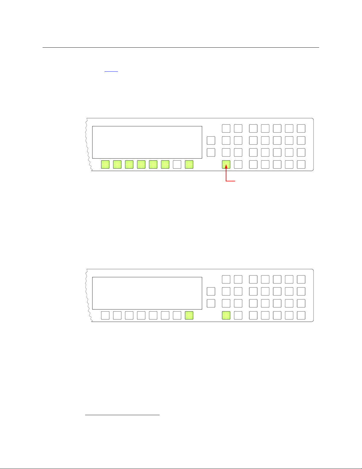
Operation
Menu Software 1
User 2
Panel 3
Illumination 4
Salvo 5
Force Release 6
Exit 8
Menu button in these examples
Menu
Software Server SV0921-06
Panel Boot SV0993-020000
Panel Application SV0000-000000
Exit 8
Menu Mode
To exit salvo mode, press the ‘Salvo’ button once again.
See the Salvo
Menu Mode
The NV9601 enters menu mode when you press a menu button.
The menu has 6 menu choices and an exit function:
Press the selection button corresponding to ‘Exit’ when you want to leave the menu and return
to normal operating mode. Otherwise, press any of the selection buttons to access the corresponding submenu.
You can also press the ‘Menu’ button again to leave the menu and return to normal operating
mode.
button definition on page 46.
Software Versions
Press selection button 1 (corresponding to ‘Software’) to view the software and firmware
versions:
Press selection button 8, corresponding to ‘Exit’, to return to the main menu.
1. Other panels have different forms of “salvo mode.”
52
Page 63

NV9601
Menu User EnvyUser
User User ID 1
Exit 8
Menu Panel Name NV9601_1
Panel Panel ID 6011
Cfg File NV9601_1
Use Host Name NVCONFIG
Keypad to IP Address 192.168.97.3
change ID
Cancel 7
Save 8
123
456
789
0
User’s Guide
User
From the main menu, press selection button 2, corresponding to ‘User’ to view user data:
These are not the Windows user name or ID.
User names are important in lock, protect, and release situations. The user who “owns” a lock
or protect is identified by a user name.
Press selection button 8, corresponding to ‘Exit’, to return to the main menu.
Panel
From the main menu, press selection button 3, corresponding to ‘Panel’ to view panel data or
change the panel ID:
When this sub-menu appears, the numeric keypad becomes enabled (and illuminated). The
keypad represents the numbers shown here, although the numbers do not appear on the actual
buttons of the panel. The panel’s button legends will probably be related to device categories.
Use the keypad to enter a new panel ID. The new entry appears in place of the dashes in the
display.
Press selection button 7 to cancel your entry and return to the main menu.
Press selection button 8 to save the new panel ID and leave menu mode, returning to normal
operating mode.
The panel submenu also shows the panel’s IP address.
The panel acquires its IP address through DHCP on the system controller’s panel/router
network unless someone in your administration has used the Static Panel Configuration
Utility to force the panel to have a static IP address.
53
Page 64

Operation
Menu Use 40% Low 1
Illumination Arrows 100% High 2
Cancel 7
Save 8
Menu Start Salvo Record 1
Salvo Pause Salvo Record 2
Save Salvo 3
Cancel Salvo Record 4
Clear Local Salvo 5
Exit 8
Menu Mode
Illumination
Press selection button 4, corresponding to ‘Illumination’ to view and change button brightness.
The illumination submenu appears:
Press selection button 1 to enable changes to the low-tally illumination level.
Press selection button 2 to enable changes to the high-tally illumination level.
Press the ‘Page Up’ or ‘Page Down’ buttons to change the illumination values in increments of
10%. The right-hand array of 20 buttons shows the illumination level for green and for amber.
The illumination levels are constrained so that high-tally is always brighter than low-tally. The
defaults are 40% for low-tally and 100% brightness for high-tally.
Press selection button 7 to cancel your entry and return to the main menu.
Press selection button 8 to save the new levels and return to the main menu.
Salvo
From the main menu, press selection button 5, corresponding to ‘Salvo’ to view the salvo
submenu:
The salvo submenu lets you create and delete local salvos. A local salvo is one that you create
by recording actions that you perform at your panel. After recording the salvo, you must name
and store the salvo.
Configurers and operators note: local salvos cannot be stored in an NV915 permanently. If
There are 5 commands in the salvo menu:
54
the NV915 is ever restarted, you will not be able to retrieve locally defined salvos. The names
of the local salvos persist, however, but the salvos are “empty.” The NV920 and NV960 do not
have this limitation.
• Start Salvo Record.
• Pause Salvo Record.
• Save Salvo.
• Cancel Salvo Record.
• Clear Local Salvo.
Page 65

NV9601
Menu Stop Salvo Record 1
Salvo Pause Salvo Record 2
Save Salvo 3
Cancel Salvo Record 4
Clear Local Salvo 5
Exit 8
Menu
Salvo
Save
Selection button to save salvo,
Clear to cancel, LSVO1 5
Or Menu to exit. LSVO2 6
Menu
Salvo
Erase
Selection button to erase salvo,
Clear to cancel, LSVO1 5
Or Menu to exit. LSVO2 6
User’s Guide
Some of the selection buttons corresponding to the commands will become enabled and the
others will become disabled as you progress.
For instance, you cannot pause a salvo recording until you have started recording. That is why
the selection button for ‘Start’ is initially enabled and the selection button for ‘Pause’ is disabled.
Once you have started recording, the ‘Start’ button becomes a ‘Stop’ button.
To re cord a salv o :
1 Press selection button 1 to start recording.
2 Press the menu button to return to normal operating mode.
3 Carry out the tasks that you want to be included in the salvo, in the order you want the tasks
to occur.
4 Press the menu button and then press selection button 5 to return to the salvo menu.
5 To finish recording the salvo, press selection button 1 (Stop Salvo Record).
6 To save the salvo, press selection button 3.
Choose a locally defined salvo name from the list:
To erase a salvo, press selection button 5 (Clear Local salvo) and choose a salvo. You might need
to scroll to see the salvo you want to erase.
This will erase the commands in the salvo, but it will not remove the local salvo name from the
list of local salvos.
You might need to scroll to see the salvo name in which to store the recorded commands.
(The local salvo names were defined during panel configuration and can only be changed or
removed by reconfiguring the panel.)
55
Page 66

Operation
Menu Enable Force Release 1
Force Release
Disabled
Exit 8
Menu
PIN
Use
Keypad to enter PIN.
Cancel 7
Done 8
123
456
789
0
ACQ IP
0
Setup Mode
(The local salvo names were defined during panel configuration and can only be changed or
removed by reconfiguring the panel.)
Force Release
Press selection button 6, corresponding to ‘Force Release’ to view and change the force release
state for your panel:
Press selection button 1 to enable or disable force release.
A submenu requesting a PIN appears:
Enter your PIN using the keypad. Your PIN is always
Press selection button 7 to cancel your entry and return to the ‘Force Release’ submenu.
Press selection button 8 to confirm your PIN and return to the ‘Force Release’ submenu. If you
enter an incorrect PIN, the panel displays a “bad PIN” message.
Setup Mode
Setup mode occurs when the NV9601 is disconnected from its network and is freshly powered
up. In setup mode, you can set or change the panel ID, determine software versions, and
perform a test of the panel’s buttons. It is in setup mode that you must initially set the panel ID.
The panel powers up with 1 button illuminated in green:
It can take 30 seconds for the button to illuminate.
The “ACQ IP” status message remains until you connect the panel to its network.
56
3689. It is not possible to change the PIN.
Page 67

Press the green button (normally the ‘Page Up’ button) to view the setup menu:
Firmware Menu Panel ID
Software
Test
Exit
Firmware Menu
Panel ID Panel ID 0
Use Keypad to Change ID
6011
Cancel
Save
123
456
789
0
Firmware Menu
Software
Panel Application SV0993-02 A0
Exit
In this menu, you have 3 options:
• Set the panel ID.
• View the software versions.
• Perform a panel test.
To select an option, press the corresponding selection button.
To leave the setup menu, press selection button 8.
Panel ID Entry
NV9601
User’s Guide
In the firmware menu, press selection button 1, corresponding to ‘Panel ID’, to set the panel ID.
The panel ID submenu appears:
Use the keypad at the right to enter a panel ID.
To make the ID permanent, press selection button 8 (‘Save’). To cancel your entry, press selection
button 7 (‘Cancel’). In either case, you will be returned to the setup menu.
Software Versions
In the firmware menu, press selection button 2, corresponding to ‘Software’. The software
submenu appears:
To return to the firmware menu, press selection button 8.
57
Page 68

Operation
Setup Mode
Te st
In the firmware menu, press selection button 3, corresponding to ‘Test’. The first of several test
patterns appears:
The first test pattern illuminates rows of pixels in the display.
Selection button 8 is illuminated. Press that button to proceed through the other test patterns.
These are the remaining test patterns, in order:
• All buttons are illuminated in low-tally amber.
• All buttons are illuminated in high-tally amber.
• All buttons are illuminated in low-tally green.
• All buttons are illuminated in high-tally green.
• Button test.
In this test, you may press any button. It will blink rapidly for a few moments. When you are
satisfied that the buttons work, press selection button 8 to return to the firmware menu.
When you are finished using the setup menu, press ‘Exit’ to return to the firmware menu.
Press ‘Exit’ again to leave the firmware menu.
58
Page 69

Chapter 6 provides electrical and mechanical specifications for the NV9601.
Topics
Power Specifications . . . . . . . . . . . . . . . . . . . . . . . . . . . . . . . . . . . . . . . . . . . . . . . . . . . . . . . . . . . . . . . . . . . . . . 59
NV9601 Specifications
Environmental Specifications
Defaults
Drawings
. . . . . . . . . . . . . . . . . . . . . . . . . . . . . . . . . . . . . . . . . . . . . . . . . . . . . . . . . . . . . . . . . . . . . . . . . . . . . . . . . . 60
. . . . . . . . . . . . . . . . . . . . . . . . . . . . . . . . . . . . . . . . . . . . . . . . . . . . . . . . . . . . . . . . . . . . . . . . . . . . . . . . . 61
Power Specifications
NV9601 Power Specifications
Specification Detail
AC power 90–250 VAC, 50–60 Hz, auto-sensing.
Power consumption < 20
Regulatory UL listed and CE compliant.
Technical Details
. . . . . . . . . . . . . . . . . . . . . . . . . . . . . . . . . . . . . . . . . . . . . . . . . . . . . . . . . . . . . . . . . . . . 59
. . . . . . . . . . . . . . . . . . . . . . . . . . . . . . . . . . . . . . . . . . . . . . . . . . . . . . . . . . . . . 60
Inrush current < 50 A at 230 VAC, cold start, at 25 °C,
Input current < 2.0 A rms at 115 VAC; < 1.0 A at 230 VAC.
W
NV9601 Specifications
NV9601 Physical Specifications
Specification Detail
Dimensions Height: 3.47 in (88.1mm), fits EIA 2 RU (3.5 in or 88.9mm),
Depth 8.61± 0.01 in (218.7 mm), enclosure.
Weight 9.8 lb (4.45 kg).
Connectors Power: AC.
Grounding terminal None.
Width: 19.0 in (482.6mm).
9.17 in (232.9mm) overall.
Ethernet: 1 connector, 10baseT, RJ-45 jack.
RS-232: 1 connector, 9-pin D type, for diagnostics and upgrades.
59
Page 70

Technical Details
n.c.
1
5
9
6
Tx
Rx
Gnd
n.c.
n.c.
n.c.
n.c.
n.c.
Environmental Specifications
The RS-232 connector has this pinout:
Pins 1, 4, and 6 are tied together and pins 7 and 8 are tied together. None of those pins are
connected to any circuitry.
Environmental Specifications
NV9601 Environmental Specifications
Specification Detail
Operating temperature 0–40 °C, ambient.
Relative humidity 0 to 90%, non-condensing.
Cooling No fan required.
Defaults
Initial Panel State
Multi-destination mode or X-Y mode, selectable.
Destination: the configured default.
Buttons: high-tally is maximum brightness; low-tally is low brightness.
Configuration Page
The default panel options are:
Panel type: XY/multi-destination mode.
Preset Monitor: None
Status Monitor: None
Default mode: Normal.
Release mode: Normal.
Default destination: None.
XY Data Routing: Automatic.
MD Data Routing: Automatic.
Default name set: System names
Multidest Device Limit: 8. (This is the lowest value. The upper limit is 512.)
Use continuous scrolling Enabled (checkbox checked).
All other options: Disabled (check boxes clear).
60
Page 71

Drawings
NV9601
User’s Guide
DHCP
The panel is set up to respond to DHCP from the factory. It is possible to assign the panel a fixed
IP address using the Panel IP Configuration Utility.
The drawings on the following pages identify features and provide overall and critical
dimensions.
61
Page 72

Technical Details
3.00
[76.2]
3.47
[88.1]
19.0 [482.6]
Drawings
Fig. 6-1: Front View of the NV9601
62
Page 73

NV9601
8.61
[218.7]
9.17
[232.9]
0.15 [3.8]
3.00
[76.2]
3.47
[88.1]
19.0 [482.6]
17.38 [441.5]
User’s Guide
Fig. 6-2: Rear and Top Views of the NV9601
63
Page 74

Technical Details
Drawings
64
Page 75

Glossary
AES/EBU (Audio Engineering Society/European Broadcasting Union). AES and EBU are standards
organizations.
Breakaway A condition where a destination has multiple sources on different levels.
Category A category represents a set of devices. (The concept of categories exists to make it easier to
select devices at a control panel.) A category can contain sources, destinations, or devices that
are both sources and destinations. Each device in the category has a unique selection index
within that category. Each category has a mnemonic ID associated with it.
The NV9601 does not support categories or category selection.
Data routing Data routing (a.ka., machine control routing) is a bidirectional form of routing. Routes are char-
acterized by a controlling device and controlled device(s). The NV9601 provides certain data
routing options including a ‘Broadcast’ button.
Device A “device” is a grouping of input and output ports that define a logical entity. (The logical entity
often represents a real device, but it does not have to be a real entity.) For example, a system
might have 3 levels: video, AES, and time code. A hypothetical device in this system is Camera 1,
which consists of video on input port 1 of the video router, AES on input port 5 of the AES router,
and time code on input port 8 of the time code router.
GPIO General Purpose Input and Output. A generic term for the NV9601’s tally interface. The tally
interface is called the “GPI Interface” at the rear of the NV9601.
Level set A level set is a group of virtual levels that are commonly used together when switching devices.
A level set also defines the mapping of each virtual level within the level set to a single physical
level. All levels in a level set have a unique display index within that level set.
Multi-Destination
(Mode)
Operator The term operator (a.k.a. user) usually refers to users other than the system administrator or
Physical level Multiple routers provide different “physical levels” on which to switch the signals of devices. Any
PIN The system administrator may create a single “super user” personal identification number (PIN)
Port A port is the physical connection on a router. A port can only be an input port or an output port.
Salvo A salvo is a stored group of commands that can be recalled and executed at an NV9000 control
Source/
Destination
A mode on an NV9000 control panel that presents many destinations at once, in contrast to X-Y
mode. An operator may route sources to multiple destinations in a single take. Multi-destination
mode does not permit the selection of breakaway levels.
configurer. An operator is responsible for making the routes.
particular device might send or receive HD, SD, AES, time-code, or machine-code signals.
that functions as a passcode. A PIN is 4–6 digits in length. The PIN allows certain operators to
perform functions such as (1) forced release on a control panel that is configured for normal
release or (2) changing the ID of a control panel.
panel.
The term “source device” is used interchangeably with “source” and the term “destination
device” is used interchangeably with “destination.” A source is a device that is connected to one
65
Page 76

Glossary
or more input ports. A destination is a device that is connected to one or more output ports. An
example of such a device would be a monitor.
A device can be both a source and destination. An example of such a device is a VTR.
System
administrator
Tally (1) High or low button illumination.
Virtual level Virtual levels allow the system administrator to define a single physical router level as multiple
X-Y (mode) A mode on an NV9000 control panel that switches one destination at a time, in contrast to multi-
The system administrator is the person responsible for installing, configuring, and maintaining a
router control system.
(2) Tally interface to be defined.
levels. Within a physical level, any port can be mapped to any virtual level. For example, an AES
matrix could be divided into AES 1/2 and AES 3/4 virtual levels.
destination mode. In X-Y mode, some panels can display the virtual levels for the selected destination. Operators using those panels can perform breakaway level selection and level mapping.
66
Page 77

Index
A
AC power cord . . . . . . . . . . . . . . . . . . . . . . . . . . . . . . . . . . . . . . . 9
Acquiring IP address (message) . . . . . . . . . . . . . . . . . . .10, 56
Acrobat usage
bookmarks . . . . . . . . . . . . . . . . . . . . . . . . . . . . . . . . . . . . . . . 1
hyperlinks . . . . . . . . . . . . . . . . . . . . . . . . . . . . . . . . . . . . . . . . 1
navigating and searching . . . . . . . . . . . . . . . . . . . . . . . . . 1
Add control panel (button) . . . . . . . . . . . . . . . . . . . . . . . . . . . 14
Add HW panel (page) . . . . . . . . . . . . . . . . . . . . . . . . . . . . . . . . 14
AES (Audio Engineering Society) . . . . . . . . . . . . . . . . . . . . . 65
AES/EBU . . . . . . . . . . . . . . . . . . . . . . . . . . . . . . . . . . . . . . . . . . . . . 65
Africa, contact . . . . . . . . . . . . . . . . . . . . . . . . . . . . . . . . . . . . . . . 73
Agreement, license . . . . . . . . . . . . . . . . . . . . . . . . . . . . . . . . . . .iii
Alphanumeric display . . . . . . . . . . . . . . . . . . . . . . . 5, 13, 33, 44
Americas, contact . . . . . . . . . . . . . . . . . . . . . . . . . . . . . . . . . . . . 73
Asia, contact . . . . . . . . . . . . . . . . . . . . . . . . . . . . . . . . . . . . . . . . . 73
Automatic data routing . . . . . . . . . . . . . . . . . . . . . . . . . . . . . . 50
B
Bookmarks, Acrobat . . . . . . . . . . . . . . . . . . . . . . . . . . . . . . . . . . 1
Breakaway . . . . . . . . . . . . . . . . . . . . . . . . . .8, 24, 36–37, 48, 65
Brightness, LCD . . . . . . . . . . . . . . . . . . . . . . . . . . . . . . . . . . .45, 60
Broadcast (button) . . . . . . . . . . . . . . . . . . . . . 23, 40, 47, 49–50
Broadcast data routing . . . . . . . . . . . . . . . . . . . . . . . . . . . . . . . 8
Broadcast mode . . . . . . . . . . . . . . . . . . . . . . . . . . . . . . . . . . . . . 50
Broadcast routes . . . . . . . . . . . . . . . . . . . . . . . . . . . . . . . . . . . . . 49
Button
add control panel . . . . . . . . . . . . . . . . . . . . . . . . . . . . . . . . 14
broadcast . . . . . . . . . . . . . . . . . . . . . . . . . 23, 40, 47, 49–50
cancel . . . . . . . . . . . . . . . . . . . . . . . . . . . . . . . . . . . . . . . . . . . 57
category . . . . . . . . . . . . . . . . . . . . . . . . . . . . . . . . . 23, 39–40
chop . . . . . . . . . . . . . . . . . . . . . . . . . . . . . . . . . . . . . 23, 40, 51
clear . . . . . . . . . . . . . . . . . . . . . . . . . . . . . . . . . . . . . . . . . . . . 41
clear preset . . . . . . . . . . . . . . . . . . . . . . . . . . . . . . . 17, 23, 41
default state . . . . . . . . . . . . . . . . . . . . . . . . . . . . . . . . . .23, 41
destination . . . . . . . . . . . . . . . . . . . . . . . . . . . . . . . 23, 39, 41
destination lock . . . . . . . . . . . . . . . . . . . . . . . . . . 24, 39, 41
destination mode . . . . . . . . . . . . . . . . . . . . . . . . . . . . .24, 41
destination protect . . . . . . . . . . . . . . . . . . . . . . . 24, 39, 42
edit panel configuration . . . . . . . . . . . . . . . . . . . . . . . . . 15
finish . . . . . . . . . . . . . . . . . . . . . . . . . . . . . . . . . . . . . . . . . . . . 14
free source . . . . . . . . . . . . . . . . . . . . . . . . . . . . . . . . 8, 24, 42
hold . . . . . . . . . . . . . . . . . . . . . . . . . . . . . . . . 7, 20, 24, 42–43
information . . . . . . . . . . . . . . . . . . . . . . . . . . . . . . . . . .24, 44
level map . . . . . . . . . . . . . . . . . . . . . . . . . . . . . . . . . . . . .24, 43
lock . . . . . . . . . . . . . . . . . . . . . . . . . . . . . . . . . . . . . . .24, 39, 44
menu . . . . . . . . . . . . . . . . . . . . . . . . . . . . . . . . . . 7, 24, 45, 52
name set toggle . . . . . . . . . . . . . . . . . . . . . . . . 6, 25, 45, 49
next . . . . . . . . . . . . . . . . . . . . . . . . . . . . . . . . . . . . . . . . . . . . .14
page down . . . . . . . . . . . . . . . . . . . . . . . . . . . . . . . . . . . . . .34
page up . . . . . . . . . . . . . . . . . . . . . . . . . . . . . . . . . . . . . 10, 34
panel lock . . . . . . . . . . . . . . . . . . . . . . . . . . . . . . . . . . . . 25, 45
preset release . . . . . . . . . . . . . . . . . . . . . . . . . . . . . . . . 25, 45
previous source . . . . . . . . . . . . . . . . . . . . . . . . . . . . 8, 25, 45
protect . . . . . . . . . . . . . . . . . . . . . . . . . . . . . . . . . . .25, 39, 45
quick source . . . . . . . . . . . . . . . . . . . . . . . . . . . . . . . . . 25, 46
revert to saved . . . . . . . . . . . . . . . . . . . . . . . . . . . . . . . 16–17
salvo . . . . . . . . . . . . . . . . . . . . . . . . . . . . . . . . . . . . . . . . . 25, 46
save . . . . . . . . . . . . . . . . . . . . . . . . . . . . . . . . . . . . . 16–17, 57
save preset . . . . . . . . . . . . . . . . . . . . . . . . . . . . 7, 20, 25, 47
scroll . . . . . . . . . . . . . . . . . . . . . . . . . . . . . . . . . . . . . . . . 25, 47
source . . . . . . . . . . . . . . . . . . . . . . . . . . . . .26, 32, 39, 47, 49
source is master . . . . . . . . . . . . . . . . . . . . . . . 21, 26, 47, 50
source mode . . . . . . . . . . . . . . . . . . . . . . . . . . . . . . . . . . . . .47
source/destination . . . . . . . . . . . . . . . . . . . . . . . . . . . . 8, 26
src/dst mode . . . . . . . . . . . . . . . . . . . . . . . . . . . . . . . . . 26, 48
take . . . . . . . . . . . . . . . . . . . . . . . . . . . . . . . . . . 17, 26, 45, 48
undefined . . . . . . . . . . . . . . . . . . . . . . . . . . . . . . . . . . . 26, 48
virtual levels contract . . . . . . . . . . . . . . . . . . . . .26, 37, 48
virtual levels expand . . . . . . . . . . . . . . . . . . . . . .26, 37, 48
XY/MD mode . . . . . . . . . . . . . . . . . . . . . . . . . . . . .26, 34, 48
Button classes . . . . . . . . . . . . . . . . . . . . . . . . . . . . . . . . . . . . 22, 39
Button color . . . . . . . . . . . . . . . . . . . . . . . . . . . . . . . . . . . . . . . . .35
Button definitions . . . . . . . . . . . . . . . . . . . . . . . . . . . . . . . . 17, 22
Button functions . . . . . . . . . . . . . . . . . . . . . . . . . . . . . . . . . . . . .39
Button illumination . . . . . . . . . . . . . . . . . . . . . . . . . . . . . . . . . .54
Button legends . . . . . . . . . . . . . . . . . . . . . . . . . . . . . . . . . . . 4, 35
Button types . . . . . . . . . . . . . . . . . . . . . . . . . . . . . . . . . . . . . . . . .22
during configuration . . . . . . . . . . . . . . . . . . . . . . . . . . . . .23
Buttons
commitment . . . . . . . . . . . . . . . . . . . . . . . . . . . . . . . . . . . . .17
control panel . . . . . . . . . . . . . . . . . . . . . . . . . . . . . . . . . . . . . 2
function . . . . . . . . . . . . . . . . . . . . . . . . . . . . . . . . . . . . . . . . . .4
selection . . . . . . . . . . . . . . . . . . . . . . . . . . . . . . . . . . . . . . 7, 27
C
Cable, Ethernet . . . . . . . . . . . . . . . . . . . . . . . . . . . . . . . . . . . . . .10
Cancel (button) . . . . . . . . . . . . . . . . . . . . . . . . . . . . . . . . . . . . . .57
Category (button) . . . . . . . . . . . . . . . . . . . . . . . . . . . . 23, 39–40
Category (defined) . . . . . . . . . . . . . . . . . . . . . . . . . . . . . . . . . . .65
Cautions . . . . . . . . . . . . . . . . . . . . . . . . . . . . . . . . . . . . . . . . . . . . . . v
67
Page 78

Index
CE . . . . . . . . . . . . . . . . . . . . . . . . . . . . . . . . . . . . . . . . . . . . . . . . . . . .iii
Change history . . . . . . . . . . . . . . . . . . . . . . . . . . . . . . . . . . . . . . .iii
Chapter structure . . . . . . . . . . . . . . . . . . . . . . . . . . . . . . . . . . . . . 1
Chapters
1, Preface . . . . . . . . . . . . . . . . . . . . . . . . . . . . . . . . . . . . . . . . . 1
2, Introduction . . . . . . . . . . . . . . . . . . . . . . . . . . . . . . . . . . . 3
3, Installation . . . . . . . . . . . . . . . . . . . . . . . . . . . . . . . . . . . . . 9
4, Configuration . . . . . . . . . . . . . . . . . . . . . . . . . . . . . . . . . 13
5, Operation . . . . . . . . . . . . . . . . . . . . . . . . . . . . . . . . . . . . . 33
6, Technical Details . . . . . . . . . . . . . . . . . . . . . . . . . . . . . . 59
Checkbox options . . . . . . . . . . . . . . . . . . . . . . . . . . . . . . . . . . . 20
China, contact . . . . . . . . . . . . . . . . . . . . . . . . . . . . . . . . . . . . . . . 73
Chop . . . . . . . . . . . . . . . . . . . . . . . . . . . . . . . . . . . . . . . . . . . . . . . . 51
Chop (button) . . . . . . . . . . . . . . . . . . . . . . . . . . . . . . . . 23, 40, 51
Clear (button) . . . . . . . . . . . . . . . . . . . . . . . . . . . . . . . . . . . . . . . 41
Clear preset (button) . . . . . . . . . . . . . . . . . . . . . . . . . . 17, 23, 41
Color, button . . . . . . . . . . . . . . . . . . . . . . . . . . . . . . . . . . . . . . . . 35
Commitment buttons . . . . . . . . . . . . . . . . . . . . . . . . . . . . . . . . 17
Configuration . . . . . . . . . . . . . . . . . . . . . . . . . . . . . . . . . . . . . . . . 2
button types for . . . . . . . . . . . . . . . . . . . . . . . . . . . . . . . . . 23
NV9601 . . . . . . . . . . . . . . . . . . . . . . . . . . . . . . . . . . . . . . . . . 13
options . . . . . . . . . . . . . . . . . . . . . . . . . . . . . . . . . . . . . . . . . . 14
page . . . . . . . . . . . . . . . . . . . . . . . . . . . . . . . . . . . . . . . . . . . . 16
page, default . . . . . . . . . . . . . . . . . . . . . . . . . . . . . . . . .16, 60
pane . . . . . . . . . . . . . . . . . . . . . . . . . . . . . . . . . . . . . . . . . . . . 14
tasks . . . . . . . . . . . . . . . . . . . . . . . . . . . . . . . . . . . . . . . . . . . . 17
Connectors
Ethernet . . . . . . . . . . . . . . . . . . . . . . . . . . . . . . . . . . . . . . . . . 10
RJ-45 . . . . . . . . . . . . . . . . . . . . . . . . . . . . . . . . . . . . . . . . . . . . 10
RS-232 . . . . . . . . . . . . . . . . . . . . . . . . . . . . . . . . . . . . . . . . . . 60
Contact Miranda . . . . . . . . . . . . . . . . . . . . . . . . . . . . . . . . . . . . . 73
Continuous scrolling . . . . . . . . . . . . . . . . . . . . . . . . . . . . . . . . . 21
Control panel . . . . . . . . . . . . . . . . . . . . . . . . . . . . . . . . 2, 9–10, 65
buttons . . . . . . . . . . . . . . . . . . . . . . . . . . . . . . . . . . . . . . . . . . 2
installation . . . . . . . . . . . . . . . . . . . . . . . . . . . . . . . . . . . . . . 10
NV96xx . . . . . . . . . . . . . . . . . . . . . . . . . . . . . . . . . . . . . . . .9, 65
Control panels (page) . . . . . . . . . . . . . . . . . . . . . . . . . . . . 14–15
Control system . . . . . . . . . . . . . . . . . . . . . . . . . . . . . . . . . . . . . . 36
Control system, NV9000 . . . . . . . . . . . . . . . . . . . . . . . . . . . . . 66
Controlled device . . . . . . . . . . . . . . . . . . . . . . . . . . . . . . . . . . . . 40
Controlling device . . . . . . . . . . . . . . . . . . . . . . . . . . . . . . . . . . . 40
Corporate office, contact . . . . . . . . . . . . . . . . . . . . . . . . . . . . . 73
Customer support . . . . . . . . . . . . . . . . . . . . . . . . . . . . . . . . . . . 73
Default
destination . . . . . . . . . . . . . . . . . . . . . . . . . . . . . . . . . . 18, 60
hold preset . . . . . . . . . . . . . . . . . . . . . . . . . . . . . . . . . . . . . .20
NV9601 configuration page . . . . . . . . . . . . . . . . . . 16, 60
save preset . . . . . . . . . . . . . . . . . . . . . . . . . . . . . . . . . . . . . .20
source is master . . . . . . . . . . . . . . . . . . . . . . . . . . . . . . . . . .21
Default mode, panel . . . . . . . . . . . . . . . . . . . . . . . . . . . . . . . . .60
Default name set (option) . . . . . . . . . . . . . . . . . . . . . . . . 20, 60
Default state (button) . . . . . . . . . . . . . . . . . . . . . . . . . . . . 23, 41
Defaults . . . . . . . . . . . . . . . . . . . . . . . . . . . . . . . . . . . . . . . . . . . . .60
Deselect all destinations and turn off hold
after take (option) . . . . . . . . . . . . . . . . . . . . . . . . . .21
Destination . . . . . . . . . . . . . . . . . . . . . . . . . . . . . . . . . . . . . . . . . .21
default . . . . . . . . . . . . . . . . . . . . . . . . . . . . . . . . . . . . . . . 18, 60
lock, enabled . . . . . . . . . . . . . . . . . . . . . . . . . . . . . . . . . . . .21
locks . . . . . . . . . . . . . . . . . . . . . . . . . . . . . . . . . . . . . . . . . . . . .39
protect, enabled . . . . . . . . . . . . . . . . . . . . . . . . . . . . . . . . .21
protects . . . . . . . . . . . . . . . . . . . . . . . . . . . . . . . . . . . . . . . . .39
Destination (button) . . . . . . . . . . . . . . . . . . . . . . . . . .23, 39, 41
Destination (defined) . . . . . . . . . . . . . . . . . . . . . . . . . . . . . . . . .65
Destination lock (button) . . . . . . . . . . . . . . . . . . . . . .24, 39, 41
Destination mode . . . . . . . . . . . . . . . . . . . . . . . . . . . . .34, 41, 48
Destination mode (button) . . . . . . . . . . . . . . . . . . . . . . . 24, 41
Destination protect (button) . . . . . . . . . . . . . . . . . . .24, 39, 42
Device (defined) . . . . . . . . . . . . . . . . . . . . . . . . . . . . . . . . . . . . .65
Device limit, MD mode . . . . . . . . . . . . . . . . . . . . . . . . . . . 20, 60
Devices
source . . . . . . . . . . . . . . . . . . . . . . . . . . . . . . . . . . . . . . . . . . .21
switching . . . . . . . . . . . . . . . . . . . . . . . . . . . . . . . . . . . . . . . .65
DHCP . . . . . . . . . . . . . . . . . . . . . . . . . . . . . . . . . . .9–10, 12, 53, 61
Dimensions . . . . . . . . . . . . . . . . . . . . . . . . . . . . . . . . . . . . . . . . . .61
Disabled buttons . . . . . . . . . . . . . . . . . . . . . . . . . . . . . . . . . . . . .35
Display . . . . . . . . . . . . . . . . . . . . . . . . . . . . . . . . . . . . 5, 13, 33, 44
Document revision . . . . . . . . . . . . . . . . . . . . . . . . . . . . . . . . . . . iii
Documentation . . . . . . . . . . . . . . . . . . . . . . . . . . . . . . . . . . . . . .10
other . . . . . . . . . . . . . . . . . . . . . . . . . . . . . . . . . . . . . . . . . . . . .2
Drawings . . . . . . . . . . . . . . . . . . . . . . . . . . . . . . . . . . . . . . . . . . . .61
NV9601, front view . . . . . . . . . . . . . . . . . . . . . . . . . . . . . . .62
NV9601, rear view . . . . . . . . . . . . . . . . . . . . . . . . . . . . . . . .63
NV9601, top view . . . . . . . . . . . . . . . . . . . . . . . . . . . . . . . .63
Dubbing applications . . . . . . . . . . . . . . . . . . . . . . . . . . . . . . . .40
E
D
Data routing . . . . . . . . . . . . . . . . . . . . . . . . . . . . . . . . . . . . . . . . . . 8
Data routing (defined) . . . . . . . . . . . . . . . . . . . . . . . . . . . . . . . 65
Data routing (options) . . . . . . . . . . . . . . . . . . . . . . . . . . . 50–51
Data routing mode
MD . . . . . . . . . . . . . . . . . . . . . . . . . . . . . . . . . . . . . . . . . . .19, 60
XY . . . . . . . . . . . . . . . . . . . . . . . . . . . . . . . . . . . . . . . . . . . .19, 60
Declaration of Conformance . . . . . . . . . . . . . . . . . . . . . . . . . . iii
68
EBU . . . . . . . . . . . . . . . . . . . . . . . . . . . . . . . . . . . . . . . . . . . . . . . . . .65
EC9700 (GUI) . . . . . . . . . . . . . . . . . . . . . . . . . . . . . . . . . . . . . . . . . .9
EC9710 (GUI) . . . . . . . . . . . . . . . . . . . . . . . . . . . . . . . . . . . . . . . . . .9
Edit panel configuration (button) . . . . . . . . . . . . . . . . . . . . .15
Electrostatic discharge . . . . . . . . . . . . . . . . . . . . . . . . . . . . . . . .9
E-mail address . . . . . . . . . . . . . . . . . . . . . . . . . . . . . . . . . . . . . . .73
Enable
destination lock . . . . . . . . . . . . . . . . . . . . . . . . . . . . . . . . . .21
destination protect . . . . . . . . . . . . . . . . . . . . . . . . . . . . . . .21
source lock . . . . . . . . . . . . . . . . . . . . . . . . . . . . . . . . . . . . . .20
source protect . . . . . . . . . . . . . . . . . . . . . . . . . . . . . . . . . . .21
Page 79

NV9601
User’s Guide
Environmental specifications, NV9601 . . . . . . . . . . . . . . . . 60
ESD . . . . . . . . . . . . . . . . . . . . . . . . . . . . . . . . . . . . . . . . . . . . . . . . . . 9
Ethernet cable . . . . . . . . . . . . . . . . . . . . . . . . . . . . . . . . . . . . . . . 10
Ethernet connector . . . . . . . . . . . . . . . . . . . . . . . . . . . . . . . . . . 10
Ethernet port . . . . . . . . . . . . . . . . . . . . . . . . . . . . . . . . . . . . . . . . . 4
Europe, contact . . . . . . . . . . . . . . . . . . . . . . . . . . . . . . . . . . . . . . 73
European broadcasting union (EBU) . . . . . . . . . . . . . . . . . . 65
Examples, symbol for . . . . . . . . . . . . . . . . . . . . . . . . . . . . . . . . . 2
F
Fax number . . . . . . . . . . . . . . . . . . . . . . . . . . . . . . . . . . . . . . . . . 73
FCC statement . . . . . . . . . . . . . . . . . . . . . . . . . . . . . . . . . . . . . . . .iii
Figures
NV9601, front view . . . . . . . . . . . . . . . . . . . . . . . . . . . . . . 62
NV9601, front, photo . . . . . . . . . . . . . . . . . . . . . . . . . . . . . 3
NV9601, rear view . . . . . . . . . . . . . . . . . . . . . . . . . . . . . . . 63
NV9601, rear, photo . . . . . . . . . . . . . . . . . . . . . . . . . . . . . . 4
NV9601, top view . . . . . . . . . . . . . . . . . . . . . . . . . . . . . . . . 63
Find, Acrobat . . . . . . . . . . . . . . . . . . . . . . . . . . . . . . . . . . . . . . . . . 2
Finish (button) . . . . . . . . . . . . . . . . . . . . . . . . . . . . . . . . . . . . . . . 14
Firmware menu . . . . . . . . . . . . . . . . . . . . . . . . . . . . . . . . . . . . . 10
First page, Acrobat . . . . . . . . . . . . . . . . . . . . . . . . . . . . . . . . . . . 2
Flip-flop source to preset after take . . . . . . . . . . . . . . . . . . . 21
Forced release . . . . . . . . . . . . . . . . 8, 18, 39, 41, 44–45, 56, 65
France, contact . . . . . . . . . . . . . . . . . . . . . . . . . . . . . . . . . . . . . . 73
Free source (button) . . . . . . . . . . . . . . . . . . . . . . . . . . . 8, 24, 42
Function buttons . . . . . . . . . . . . . . . . . . . . . . . . . . . . . . . . . . . . . 4
Fuse . . . . . . . . . . . . . . . . . . . . . . . . . . . . . . . . . . . . . . . . . . . . . . . . . . 4
How to
create a level mapping . . . . . . . . . . . . . . . . . . . . . . . . . . .43
initialize the NV9601 . . . . . . . . . . . . . . . . . . . . . . . . . . . . .10
install the NV9601 . . . . . . . . . . . . . . . . . . . . . . . . . . . . . . . .10
make a broadcast route . . . . . . . . . . . . . . . . . . . . . . . . . .50
use selection buttons . . . . . . . . . . . . . . . . . . . . . . . . . . . .27
use semi-automatic data routing mode . . . . . . . . . . .51
Hyperlinks, Acrobat . . . . . . . . . . . . . . . . . . . . . . . . . . . . . . . . . . . 1
I
ID, panel . . . . . . . . . . . . . . . . . . . . . . . . . . . 10–12, 20, 24, 45, 57
Illumination (menu) . . . . . . . . . . . . . . . . . . . . . . . . . . . . . . . . . .54
Information (button) . . . . . . . . . . . . . . . . . . . . . . . . . . . . . 24, 44
Information (column) . . . . . . . . . . . . . . . . . . . . . . . . . . . . . . . . . 5
Information mode . . . . . . . . . . . . . . . . . . . . . . . . . . . . . . . . . 7, 34
Initial panel state . . . . . . . . . . . . . . . . . . . . . . . . . . . . . . . . . . . . .60
Initialization . . . . . . . . . . . . . . . . . . . . . . . . . . . . . . . . . . . . . . . . .10
Initializing the NV9601 . . . . . . . . . . . . . . . . . . . . . . . . . . . . . . .10
Installation
NV9601 control panel . . . . . . . . . . . . . . . . . . . . . . . . . . . .10
package contents . . . . . . . . . . . . . . . . . . . . . . . . . . . . . . . . .9
receiving and unpacking . . . . . . . . . . . . . . . . . . . . . . . . . .9
IP address . . . . . . . . . . . . . . . . . . . . . . . . . . . . . . . . . . . . . . . . 10, 61
IP addresses . . . . . . . . . . . . . . . . . . . . . . . . . . . . . . . . . . .9–10, 12
IP configuration . . . . . . . . . . . . . . . . . . . . . . . . . . . . . . . .9–10, 61
J
G
Glossary . . . . . . . . . . . . . . . . . . . . . . . . . . . . . . . . . . . . . . . . . . . . . 65
Go to first page, Acrobat . . . . . . . . . . . . . . . . . . . . . . . . . . . . . . 2
Go to last page, Acrobat . . . . . . . . . . . . . . . . . . . . . . . . . . . . . . 2
Go to next page, Acrobat . . . . . . . . . . . . . . . . . . . . . . . . . . . . . 2
Go to next view, Acrobat . . . . . . . . . . . . . . . . . . . . . . . . . . . . . . 1
Go to previous page, Acrobat . . . . . . . . . . . . . . . . . . . . . . . . . 2
Go to previous view, Acrobat . . . . . . . . . . . . . . . . . . . . . . . . . . 1
H
Hardware symbols . . . . . . . . . . . . . . . . . . . . . . . . . . . . . . . . . . . . iv
Hazardous substance . . . . . . . . . . . . . . . . . . . . . . . . . . . . . . . . . iv
Hide sources not configured on this panel . . . . . . . . . . . . 21
High tally . . . . . . . . . . . . . . . . . . . . . . . . . . . . . . . . . . . . . . . . . . 2, 35
Hold (button) . . . . . . . . . . . . . . . . . . . . . . . . . . . 7, 20, 24, 42–43
Hold mode . . . . . . . . . . . . . . . . . . . . . 20, 24, 28, 35, 37, 43, 49
Hold preset as default . . . . . . . . . . . . . . . . . . . . . . . . . . . . . . . 20
Hours of operation . . . . . . . . . . . . . . . . . . . . . . . . . . . . . . . . . . 73
Jump to multi-dest selection when switching
to XY (option) . . . . . . . . . . . . . . . . . . . . . . . . . . . . . .21
K
Keycaps . . . . . . . . . . . . . . . . . . . . . . . . . . . . . . . . . . . . . . . . . . . . . . .4
L
Last page, Acrobat . . . . . . . . . . . . . . . . . . . . . . . . . . . . . . . . . . . .2
LCD brightness . . . . . . . . . . . . . . . . . . . . . . . . . . . . . . .24, 45, 60
LCD buttons . . . . . . . . . . . . . . . . . . . . . . . . . . . . . . . . . . . . . . . . .24
Legends, button . . . . . . . . . . . . . . . . . . . . . . . . . . . . . . . . . . 4, 35
Level . . . . . . . . . . . . . . . . . . . . . . . . . . . . . . . . . . . . . . . . . . . . . . . .24
breakaway . . . . . . . . . . . . . . . . . . . . . . . . . . . . . . . . . . . 24, 37
mapping . . . . . . . . . . . . . . . . . . . . . . . . . . . . . . . . . 36–37, 44
physical . . . . . . . . . . . . . . . . . . . . . . . . . . . . . . . . . . . . . . 65–66
sets . . . . . . . . . . . . . . . . . . . . . . . . . . . . . . . . . . . . . . . . . . . . . .65
virtual . . . . . . . . . . . . . . . . . . . . . . . . . . . . . . . . 43, 48, 65–66
Level map (button) . . . . . . . . . . . . . . . . . . . . . . . . . . . . . . . 24, 43
Level mapping . . . . . . . . . . . . . . . . . . . . . . . . . . . . . . . . . . . . . . . .8
Level set . . . . . . . . . . . . . . . . . . . . . . . . . . . . . . . . . . . . . . . . . . . . .36
69
Page 80

Index
Level/Dest (column) . . . . . . . . . . . . . . . . . . . . . . . . . . . . . . . . . . 5
Levels . . . . . . . . . . . . . . . . . . . . . . . . . . . . . . . . . . . . . . . . . . . .36, 38
License . . . . . . . . . . . . . . . . . . . . . . . . . . . . . . . . . . . . . . . . . . . . . . .iii
Lists . . . . . . . . . . . . . . . . . . . . . . . . . . . . . . . . . . . . . . . . . . . . . . . . . 36
Local salvos . . . . . . . . . . . . . . . . . . . . . . . . . . . . . . . . . . . . . . . . . 54
Lock . . . . . . . . . . . . . . . . . . . . . . . . . . . . . . . . . . . . . . . . . . . . . . . . . . 8
Lock (button) . . . . . . . . . . . . . . . . . . . . . . . . . . . . . . . . . 24, 39, 44
Locked devices . . . . . . . . . . . . . . . . . . . . . . . . . . . . . . . . . . . . . . . 8
Locks . . . . . . . . . . . . . . . . . . . . . . . .20–21, 24, 33, 39, 41, 44–45
destination . . . . . . . . . . . . . . . . . . . . . . . . . . . . . . . . . . . . . . 39
source . . . . . . . . . . . . . . . . . . . . . . . . . . . . . . . . . . . . . . . . . . . 39
Low tally . . . . . . . . . . . . . . . . . . . . . . . . . . . . . . . . . . . . . . . . . .2, 35
M
Manual data routing . . . . . . . . . . . . . . . . . . . . . . . . . . . . . . . . . 50
Mapping levels . . . . . . . . . . . . . . . . . . . . . . . . . . . . .8, 36–37, 44
Mapping, virtual to physical level . . . . . . . . . . . . . . . . . . . . . 65
Marks . . . . . . . . . . . . . . . . . . . . . . . . . . . . . . . . . . . . . . . . . . . . . . . . 6
MD
device limit . . . . . . . . . . . . . . . . . . . . . . . . . . . . . . . . . . .20, 60
MD (abbreviation for multi-destination)
MD destination . . . . . . . . . . . . . . . . . . . . . . . . . . . . . . . . . . . . . . 30
Menu
firmware . . . . . . . . . . . . . . . . . . . . . . . . . . . . . . . . . . . . . . . . 10
illumination . . . . . . . . . . . . . . . . . . . . . . . . . . . . . . . . . . . . . 54
panel . . . . . . . . . . . . . . . . . . . . . . . . . . . . . . . . . . . . . . . . . . . . 53
salvo (local) . . . . . . . . . . . . . . . . . . . . . . . . . . . . . . . . . . . . . . 54
software . . . . . . . . . . . . . . . . . . . . . . . . . . . . . . . . . . . . . . . . . 52
user . . . . . . . . . . . . . . . . . . . . . . . . . . . . . . . . . . . . . . . . . . . . . 53
Menu (button) . . . . . . . . . . . . . . . . . . . . . . . . . . . . . . 7, 24, 45, 52
Menu mode . . . . . . . . . . . . . . . . . . . . . . . . . . . . 7, 24, 34, 45, 52
Messages
acquiring IP address . . . . . . . . . . . . . . . . . . . . . . . . . .10, 56
no server . . . . . . . . . . . . . . . . . . . . . . . . . . . . . . . . . . . . . . . . 11
select dest level . . . . . . . . . . . . . . . . . . . . . . . . . . . . . . . . . 43
select src level . . . . . . . . . . . . . . . . . . . . . . . . . . . . . . . . . . . 43
Middle East, contact . . . . . . . . . . . . . . . . . . . . . . . . . . . . . . . . . 73
Miranda, contact . . . . . . . . . . . . . . . . . . . . . . . . . . . . . . . . . . . . 73
Mode
broadcast . . . . . . . . . . . . . . . . . . . . . . . . . . . . . . . . . . . . . . . 50
data routing . . . . . . . . . . . . . . . . . . . . . . . . . . . . . . . . . .19, 60
default panel . . . . . . . . . . . . . . . . . . . . . . . . . . . . . . . . . . . . 60
destination . . . . . . . . . . . . . . . . . . . . . . . . . . . . . . . 34, 41, 48
hold . . . . . . . . . . . . . . . . . . . . . . . . 20, 24, 28, 35, 37, 43, 49
information . . . . . . . . . . . . . . . . . . . . . . . . . . . . . . . . . . . 7, 34
menu . . . . . . . . . . . . . . . . . . . . . . . . . . . . . . 7, 24, 34, 45, 52
multidest . . . . . . . . . . . . . . . . . . . . . . . . . . . . . . . . . . . . . . . . . 5
multi-destination . . . . . . . 3, 7–8, 18, 20–21, 24, 26–28,
. . . . . . . 33–35, 37, 41–42, 44, 46, 48–49, 60, 65–66
panel . . . . . . . . . . . . . . . . . . . . . . . . . . . . . . . . . . . . . . . . . . . . 18
panel test . . . . . . . . . . . . . . . . . . . . . . . . . . . . . . . . . . . . . . . 58
release . . . . . . . . . . . . . . . . . . . . . . . . . . . . . . . . . . . . . . .18, 60
salvo . . . . . . . . . . . . . . . . . . . . . . . . . . . . . . . . . . .7, 34–35, 51
save preset . . . . . . . . . . . . . . . . . . . . . . . . . . . . . . . . . . 35, 47
setup . . . . . . . . . . . . . . . . . . . . . . . . . . . . . . . . . . . . . .7, 34, 56
single-destination . . . . . . . . . . . . . . . . . .28, 30, 32, 34, 48
source . . . . . . . . . . . . . . . . . . . . . . . . . . . . . . . . 34, 42, 47–48
source is master . . . . . . . . . . . . . . . . . . . . . . . . . . . . . . . . . .50
X-Y . . . . . . . . . . . 3, 5, 7–8, 18, 21, 24, 26–28, 33–34, 37,
. . . . . . . . . . . . . . . . . . . . . 41–44, 46, 48, 51, 60, 65–66
Monitor, preset . . . . . . . . . . . . . . . . . . . . . . . . . . . . . . . . . . . . . .18
Monitor, status . . . . . . . . . . . . . . . . . . . . . . . . . . . . . . . . . . . . . . .18
Multidest mode . . . . . . . . . . . . . . . . . . . . . . . . . . . . . . . . . . . . . . .5
Multi-destination (mode) . . . . . . . . . . . . . . . . . . . . . . . . . 65–66
Multi-destination mode . . . . . . . . 3, 7–8, 18, 21, 24, 26–28,
. . . . . . . . . . . . . 33–35, 37, 41–42, 44, 46, 48–49, 60
N
Name set toggle (button) . . . . . . . . . . . . . . . . . . . 6, 25, 45, 49
Name sets . . . . . . . . . . . . . . . . . . . . . . . . . . . . . . . . 20, 25, 49, 60
Next (button) . . . . . . . . . . . . . . . . . . . . . . . . . . . . . . . . . . . . . . . .14
Next page, Acrobat . . . . . . . . . . . . . . . . . . . . . . . . . . . . . . . . . . . . 2
Next view, Acrobat . . . . . . . . . . . . . . . . . . . . . . . . . . . . . . . . . . . .1
No server (message) . . . . . . . . . . . . . . . . . . . . . . . . . . . . . . . . . .11
Normal release . . . . . . . . . . . . . . . . . . . . . . . . . . . . . . . . . . . . . . .18
NV9000
router control system . . . . . . . . . . . . . . . . . . . . . . . . . . . . .2
NV9000 configuration . . . . . . . . . . . . . . . . . . . . . . . . . . . . . . . .13
NV9000 router control system . . . . . . . . . . . . . . . . . . . . . . . .36
NV9000-SE Utilities . . . . . . . . . . . . . . . . . . . .2, 9–11, 13, 16, 36
user’s guide . . . . . . . . . . . . . . . . . . . . . . . . . . . . . . . . . . . . . . .2
NV915 system controller . . . . . . . . . . . . . . . . . . . . . . . . . . . . . .2
NV920 system controller . . . . . . . . . . . . . . . . . . . . . . . . . . . . . .2
NV960 system controller . . . . . . . . . . . . . . . . . . . . . . . . . . . . . .2
NV9601 . . . . . . . . . . . . . . . . . . . . . . . . . . . . . . . . . . . 2–3, 9–10, 13
configuration . . . . . . . . . . . . . . . . . . . . . . . . . . . . . . . . . . . .13
front view . . . . . . . . . . . . . . . . . . . . . . . . . . . . . . . . . . . . . . . .62
initialization . . . . . . . . . . . . . . . . . . . . . . . . . . . . . . . . . . . . .10
installation . . . . . . . . . . . . . . . . . . . . . . . . . . . . . . . . . . . . . . . .9
rear view . . . . . . . . . . . . . . . . . . . . . . . . . . . . . . . . . . . . . . . . .63
top view . . . . . . . . . . . . . . . . . . . . . . . . . . . . . . . . . . . . . . . . .63
NV96xx control panels . . . . . . . . . . . . . . . . . . . . . . . . . . . . 9, 65
O
Office hours . . . . . . . . . . . . . . . . . . . . . . . . . . . . . . . . . . . . . . . . . .73
Operating temperature . . . . . . . . . . . . . . . . . . . . . . . . . . . . . .60
Operator . . . . . . . . . . . . . . . . . . . . . . . . . . . . . . . . . . . . . . . . . . . . .65
Options
checkbox . . . . . . . . . . . . . . . . . . . . . . . . . . . . . . . . . . . . . . . .20
configuration . . . . . . . . . . . . . . . . . . . . . . . . . . . . . . . . . . . .14
default name set . . . . . . . . . . . . . . . . . . . . . . . . . . . . . . . . .20
panel . . . . . . . . . . . . . . . . . . . . . . . . . . . . . . . . . . . . . . . . . . . .17
Other documentation . . . . . . . . . . . . . . . . . . . . . . . . . . . . . . . . .2
70
Page 81

NV9601
User’s Guide
P
Package contents . . . . . . . . . . . . . . . . . . . . . . . . . . . . . . . . . . . . . 9
Page
add HW panel . . . . . . . . . . . . . . . . . . . . . . . . . . . . . . . . . . . 14
control panels . . . . . . . . . . . . . . . . . . . . . . . . . . . . . . . 14–15
NV9601 configuration . . . . . . . . . . . . . . . . . . . . . . . . . . . 16
Page down (button) . . . . . . . . . . . . . . . . . . . . . . . . . . . . . . . . . 34
Page up (button) . . . . . . . . . . . . . . . . . . . . . . . . . . . . . . . . .10, 34
Pane, configuration . . . . . . . . . . . . . . . . . . . . . . . . . . . . . . . . . . 14
Panel
initial state . . . . . . . . . . . . . . . . . . . . . . . . . . . . . . . . . . . . . . 60
mode . . . . . . . . . . . . . . . . . . . . . . . . . . . . . . . . . . . . . . . . . . . 18
options . . . . . . . . . . . . . . . . . . . . . . . . . . . . . . . . . . . . . . . . . . 17
organization . . . . . . . . . . . . . . . . . . . . . . . . . . . . . . . . . . . . . . 4
test mode . . . . . . . . . . . . . . . . . . . . . . . . . . . . . . . . . . . . . . . 58
Panel (menu) . . . . . . . . . . . . . . . . . . . . . . . . . . . . . . . . . . . . . . . . 53
Panel configuration . . . . . . . . . . . . . . . . . . . . . . . . . . . . . . . . . . 13
Panel configuration (page) . . . . . . . . . . . . . . . . . . . . . . . . . . . 16
Panel ID . . . . . . . . . . . . . . . . . . . . . . . . . . . .10–12, 20, 24, 45, 57
entry . . . . . . . . . . . . . . . . . . . . . . . . . . . . . . . . . . . . . . . . . . . . 57
Panel IP configuration utility . . . . . . . . . . . . . . . . . . . 9–10, 61
Panel lock (button) . . . . . . . . . . . . . . . . . . . . . . . . . . . . . . .25, 45
Panel/router network . . . . . . . . . . . . . . . . . . . . . . . . . . . . .12, 53
Panels, control . . . . . . . . . . . . . . . . . . . . . . . . . . . . . . . 2, 9–10, 65
NV96xx . . . . . . . . . . . . . . . . . . . . . . . . . . . . . . . . . . . . . . . .9, 65
PDF documents . . . . . . . . . . . . . . . . . . . . . . . . . . . . . . . . . . . . . . 1
navigating and searching . . . . . . . . . . . . . . . . . . . . . . . . . 1
Phone numbers . . . . . . . . . . . . . . . . . . . . . . . . . . . . . . . . . . . . . 73
Photos
NV9601, front . . . . . . . . . . . . . . . . . . . . . . . . . . . . . . . . . . . . . 3
NV9601, rear . . . . . . . . . . . . . . . . . . . . . . . . . . . . . . . . . . . . . 4
Physical level . . . . . . . . . . . . . . . . . . . . . . . . . . . . . . . . . . . . 65–66
PIN . . . . . . . . . . . . . . . . . . . . . . . . . . . . . . . . . . . . . . . . . . . . . . .56, 65
Port (defined) . . . . . . . . . . . . . . . . . . . . . . . . . . . . . . . . . . . . . . . . 65
Power cord . . . . . . . . . . . . . . . . . . . . . . . . . . . . . . . . . . . . . . . . . . . 9
Preface
about PDF documents . . . . . . . . . . . . . . . . . . . . . . . . . . . . 1
chapter structure . . . . . . . . . . . . . . . . . . . . . . . . . . . . . . . . . 1
terms, conventions and abbreviations . . . . . . . . . . . . . 2
Preset (column) . . . . . . . . . . . . . . . . . . . . . . . . . . . . . . . . . . . . . . . 6
Preset monitor . . . . . . . . . . . . . . . . . . . . . . . . . . . . . . . . . . .18, 60
Preset release (button) . . . . . . . . . . . . . . . . . . . . . . . . . . . .25, 45
Preset, clearing . . . . . . . . . . . . . . . . . . . . . . . . . . . . . . . . . . . . . . 41
Previous page, Acrobat . . . . . . . . . . . . . . . . . . . . . . . . . . . . . . . 2
Previous source (button) . . . . . . . . . . . . . . . . . . . . . . . 8, 25, 45
Previous view, Acrobat . . . . . . . . . . . . . . . . . . . . . . . . . . . . . . . . 1
Protect . . . . . . . . . . . . . . . . . . . . . . . . . . . . . . . . . . . . . . . . . . . . . . . 8
Protect (button) . . . . . . . . . . . . . . . . . . . . . . . . . . . . . . 25, 39, 45
Protected devices . . . . . . . . . . . . . . . . . . . . . . . . . . . . . . . . . . . . 8
Protects . . . . . . . . . . . . . . . . . . . . . . . . . . . . . . . . . . .21, 39, 42, 45
destination . . . . . . . . . . . . . . . . . . . . . . . . . . . . . . . . . . . . . . 39
source . . . . . . . . . . . . . . . . . . . . . . . . . . . . . . . . . . . . . . . . . . . 39
Q
Quick source (button) . . . . . . . . . . . . . . . . . . . . . . . . . . . . 25, 46
R
Rack mount . . . . . . . . . . . . . . . . . . . . . . . . . . . . . . . . . . . . . . . . . .10
Receiving and unpacking shipments . . . . . . . . . . . . . . . . . . . 9
Release . . . . . . . . . . . . . . . . . . . . . . . . . . . . . . . . . . . . . . . . . . . 8, 39
forced . . . . . . . . . . . . . . . . . . . . . . . . . 18, 39, 41, 44–45, 65
mode . . . . . . . . . . . . . . . . . . . . . . . . . . . . . . . . . . . . . . . . 18, 60
normal . . . . . . . . . . . . . . . . . . . . . . . . . . . . . . . . . . . . . . . . . . .18
Release, forced . . . . . . . . . . . . . . . . . . . . . . . . . . . . . . . . . . . . . . .56
Restrictions . . . . . . . . . . . . . . . . . . . . . . . . . . . . . . . . . . . . . . . . . . iv
Revert to saved (button) . . . . . . . . . . . . . . . . . . . . . . . . . . 16–17
Revision, document . . . . . . . . . . . . . . . . . . . . . . . . . . . . . . . . . . iii
RJ-45 connector . . . . . . . . . . . . . . . . . . . . . . . . . . . . . . . . . . . . . .10
RoHS . . . . . . . . . . . . . . . . . . . . . . . . . . . . . . . . . . . . . . . . . . . . . . . . iv
Router control system . . . . . . . . . . . . . . . . . . . . . . . . . . . . . . . . .2
RS-232 connector . . . . . . . . . . . . . . . . . . . . . . . . . . . . . . . . . . . .60
S
safeguards . . . . . . . . . . . . . . . . . . . . . . . . . . . . . . . . . . . . . . . . . . . iii
safety notices . . . . . . . . . . . . . . . . . . . . . . . . . . . . . . . . . . . . . . . . iii
Salvo (button) . . . . . . . . . . . . . . . . . . . . . . . . . . . . . . . . . . . . 25, 46
Salvo (defined) . . . . . . . . . . . . . . . . . . . . . . . . . . . . . . . . . . . . . . .65
Salvo (menu) . . . . . . . . . . . . . . . . . . . . . . . . . . . . . . . . . . . . . . . . .54
Salvo mode . . . . . . . . . . . . . . . . . . . . . . . . . . . . . . . . 7, 34–35, 51
Salvos . . . . . . . . . . . . . . . . . . . . . . . . . . . . . . . . . . . . . . . . . . . . . . .54
Salvos, local . . . . . . . . . . . . . . . . . . . . . . . . . . . . . . . . . . . . . . . . . .54
Salvos, system . . . . . . . . . . . . . . . . . . . . . . . . . . . . . . . . . . . . . . . .8
Save (button) . . . . . . . . . . . . . . . . . . . . . . . . . . . . . . . . 16–17, 57
Save preset
(button) . . . . . . . . . . . . . . . . . . . . . . . . . . . . . . . 7, 20, 25, 47
as default . . . . . . . . . . . . . . . . . . . . . . . . . . . . . . . . . . . . . . . .20
Save preset mode . . . . . . . . . . . . . . . . . . . . . . . . . . . . . . . . 35, 47
Scroll (button) . . . . . . . . . . . . . . . . . . . . . . . . . . . . . . . . . . . 25, 47
Scrolling . . . . . . . . . . . . . . . . . . . . . . . . . . . . . . . . . . . . . . . . . . . . .21
SE (abbreviation for NV9000-SE Utilities)
Search, Acrobat . . . . . . . . . . . . . . . . . . . . . . . . . . . . . . . . . . . . . . . 2
Select dest level (message) . . . . . . . . . . . . . . . . . . . . . . . . . . .43
Select src level (message) . . . . . . . . . . . . . . . . . . . . . . . . . . . . .43
Selection buttons . . . . . . . . . . . . . . . . . . . . . . . . . . . . . . . . . 7, 27
Selection marks . . . . . . . . . . . . . . . . . . . . . . . . . . . . . . . . . . . . . . .6
Semi-automatic data routing . . . . . . . . . . . . . . . . . . . . . . . . .51
Setup mode . . . . . . . . . . . . . . . . . . . . . . . . . . . . . . . 7, 11, 34, 56
Single-destination mode . . . . . . . . . . . . . . . 28, 30, 32, 34, 48
Software . . . . . . . . . . . . . . . . . . . . . . . . . . . . . . . . . . . . . .10, 52, 57
versions . . . . . . . . . . . . . . . . . . . . . . . . . . . . . . . . . . . . . 52, 57
Software (menu) . . . . . . . . . . . . . . . . . . . . . . . . . . . . . . . . . . . . .52
Software license . . . . . . . . . . . . . . . . . . . . . . . . . . . . . . . . . . . . . iii
Software, configuration . . . . . . . . . . . . . . . . . . . . . . . . . . . . . . .2
71
Page 82

Index
Source
devices . . . . . . . . . . . . . . . . . . . . . . . . . . . . . . . . . . . . . . . . . . 21
lock, enabled . . . . . . . . . . . . . . . . . . . . . . . . . . . . . . . . . . . . 20
locks . . . . . . . . . . . . . . . . . . . . . . . . . . . . . . . . . . . . . . . . . . . . 39
protect, enabled . . . . . . . . . . . . . . . . . . . . . . . . . . . . . . . . . 21
protects . . . . . . . . . . . . . . . . . . . . . . . . . . . . . . . . . . . . . . . . . 39
Source (button) . . . . . . . . . . . . . . . . . . . . . . . . 26, 32, 39, 47, 49
Source (defined) . . . . . . . . . . . . . . . . . . . . . . . . . . . . . . . . . . . . . 65
Source is master
as default . . . . . . . . . . . . . . . . . . . . . . . . . . . . . . . . . . . . . . . . 21
mode . . . . . . . . . . . . . . . . . . . . . . . . . . . . . . . . . . . . . . . . . . . 50
Source is master (button) . . . . . . . . . . . . . . . . . .21, 26, 47, 50
Source mode . . . . . . . . . . . . . . . . . . . . . . . . . . . . . 34, 42, 47–48
Source mode (button) . . . . . . . . . . . . . . . . . . . . . . . . . . . . . . . 47
Source/destination (button) . . . . . . . . . . . . . . . . . . . . . . .8, 26
Special messages, symbol for . . . . . . . . . . . . . . . . . . . . . . . . . 2
Specifications, environmental . . . . . . . . . . . . . . . . . . . . . . . . 60
Src/dst mode (button) . . . . . . . . . . . . . . . . . . . . . . . . . . . .26, 48
Static . . . . . . . . . . . . . . . . . . . . . . . . . . . . . . . . . . . . . . . . . . . . . . . . . 9
Status (column) . . . . . . . . . . . . . . . . . . . . . . . . . . . . . . . . . . . . . . . 5
Status monitor . . . . . . . . . . . . . . . . . . . . . . . . . . . . . . . . . . .18, 60
Support, contact . . . . . . . . . . . . . . . . . . . . . . . . . . . . . . . . . . . . . 73
Switching devices . . . . . . . . . . . . . . . . . . . . . . . . . . . . . . . . . . . 65
Symbols
for examples . . . . . . . . . . . . . . . . . . . . . . . . . . . . . . . . . . . . . 2
for special messages . . . . . . . . . . . . . . . . . . . . . . . . . . . . . . 2
Symbols, meaning . . . . . . . . . . . . . . . . . . . . . . . . . . . . . . . . . . . .iv
System administrator . . . . . . . . . . . . . . . . . . . . . . . . . . . . . . . . 66
System controller . . . . . . . . . . . . . . . . . . . . . . . . . . . . . . . . 10–12
System controllers . . . . . . . . . . . . . . . . . . . . . . . . . . . . . . . . . . . . 2
System salvos . . . . . . . . . . . . . . . . . . . . . . . . . . . . . . . . . . . . . . . . 8
T
Technical support . . . . . . . . . . . . . . . . . . . . . . . . . . . . . . . . . . . .73
Temperature, operating . . . . . . . . . . . . . . . . . . . . . . . . . . . . . .60
Terms, conventions and abbreviations . . . . . . . . . . . . . . . . .2
Testing your installation . . . . . . . . . . . . . . . . . . . . . . . . . . . . . .11
Tielines . . . . . . . . . . . . . . . . . . . . . . . . . . . . . . . . . . . . . . . . . . . . . .42
U
Undefined (button) . . . . . . . . . . . . . . . . . . . . . . . . . . . . . . 26, 48
UniConfig . . . . . . . . . . . . . . . . . . . . . . . . . . . . . . . . . . . . . . . . . . . . .9
United Kingdom, contact . . . . . . . . . . . . . . . . . . . . . . . . . . . . .73
Use continuous scrolling (option) . . . . . . . . . . . . . . . . . . . . .21
User (menu) . . . . . . . . . . . . . . . . . . . . . . . . . . . . . . . . . . . . . . . . . .53
User’s guide, chapter structure . . . . . . . . . . . . . . . . . . . . . . . .1
User-programmable panel ID . . . . . . . . . . . . . . . . . . . . . . . . .20
User-selectable (option) . . . . . . . . . . . . . . . . . . . . . . . . . . . . . .30
Using selection buttons . . . . . . . . . . . . . . . . . . . . . . . . . . . . . .27
V
Virtual level group . . . . . . . . . . . . . . . . . . . . . . . . . . . . . . . . . . .37
Virtual levels . . . . . . . . . . . . . . . . . . . . . . . . . . . . . . 43, 48, 65–66
Virtual levels contract (button) . . . . . . . . . . . . . . . . . 26, 37, 48
Virtual levels expand (button) . . . . . . . . . . . . . . . . .26, 37, 48
W
Warnings, hardware . . . . . . . . . . . . . . . . . . . . . . . . . . . . . . . . . . .v
Warranty . . . . . . . . . . . . . . . . . . . . . . . . . . . . . . . . . . . . . . . . . . . . . iii
Web site . . . . . . . . . . . . . . . . . . . . . . . . . . . . . . . . . . . . . . . . . . . . .73
Tables
environmental specifications, NV9601 . . . . . . . . . . . . 60
Take (button) . . . . . . . . . . . . . . . . . . . . . . . . . . . . . .17, 26, 45, 48
Takes . . . . . . . . . . . . . . . . . . . . . . . . . . . . . . . . . . . . . . . . . . . . .48, 65
Tally
high . . . . . . . . . . . . . . . . . . . . . . . . . . . . . . . . . . . . . . . . . . . . . . 2
low . . . . . . . . . . . . . . . . . . . . . . . . . . . . . . . . . . . . . . . . . . . . . . . 2
72
X-Y-Z
X-Y mode . . . . . . . . . . . . . 3, 5, 7–8, 18, 21, 24, 26–28, 33–34,
. . . . . . . . . . . . . . . . .37, 41–44, 46, 48, 51, 60, 65–66
XY/MD mode (button) . . . . . . . . . . . . . . . . . . . . . . . . .26, 34, 48
Page 83

Contact Us
Grass Valley Technical Support
For technical assistance, please contact the Grass Valley Technical Support center nearest you:
Americas
Office hours: 9:00 a.m. – 9:00 p.m. (EST)
Telephone: +1-800-547-8949
+1 530 478 4148
Fax: +1-514-335-1614
E-mail: support@grass valley.com
Europe, Middle East, Africa, UK
Office hours: 9:00 a.m. – 6:00 p.m. (GMT)
Telephone: +44 118 952 3444
Fax: +44 118 952 3401
E-mail: eurotech@grass valley.com
Playout Automation — Europe,
Middle East, Africa, UK
Office hours: 9:00 a.m. – 5:30 p.m. (GMT)
Telephone: +44 870 500 4350
Fax: +44 870 500 4333
automationsupport@grassvalley.com
France
Office hours: 9:00 a.m. – 5:00 p.m. (GMT+1)
Telephone: +33 1 55 86 87 88
Fax: +33 1 55 86 00 29
E-mail: eurotech@grass valley.com
Asia
Office hours: 9:30 a.m. – 6:00 p.m. (GMT+8)
Telephone: +852 2539 6987
Fax: +852 2539 0804
E-mail: asiatech@grass valley.com
China
Office hours: 9:30 a.m. – 6:00 p.m. (GMT+8)
Telephone: +86 10 5873 1814
E-mail: asiatech@grass valley.com
Malaysia
Telephone: +60 3 2247 1808
E-mail: asiatech@grass valley.com
EMERGENCY after hours (global)
Toll free: 1-800-547-8949 (US and Canada)
+1 530 478 4148
Telephone: +1 514 333 1772
Corporate Head Office
Grass Valley
3499 Douglas-B.-Floreani
St-Laurent, Quebec H4S 2C6
Canada
Telephone: +1 514 333 1772
Fax: +1 514 333 9828
Web: www.grass valley.com
73
Page 84

 Loading...