

Page 1

NV9575-VF
Video
frame
TALLY EXPANDER
POWER
AB
This guide is a compilation of information taken from the NV9000-SE Utilities help pages. It is
with NV9000-SE Utilities that you must configure the NV9575-VF.
Refer to the NV9000-SE Utilities User’s Guide (UG0007) for additional information.
Introduction
The NV575-VF is a tally interface:
This 1RU device (unlike router control panels) has no controls on its front panel. What it does have
are 64 relay outputs and 32 optically isolated inputs, typically used for tally functions.
The NV9575-VF has 6 DB25 connectors on its rear panel
— J1 through J6. J1, J2, J4, and J5 pro-
vide connections for the 64 relay outputs, 16 per connector, with 8 pins common. J3 and J6 provide
connections for the 32 inputs, also 16 per connector with 8 pins common.
Each relay can be configured to switch on a number of conditions:
• One or more routes occurring on specific levels.
• Conditions involving output ports (destination, level).
• A transition on one or more of the NV9575-VF inputs.
Each input (also called a GPI) can be configured to trigger a salvo on a transition from off to on and
to trigger another salvo on a transition from on to off.
NV9575-VF Tally Interface • User’s Guide 1
Page 2
1. NV9575-VF
Configuration
Configuration
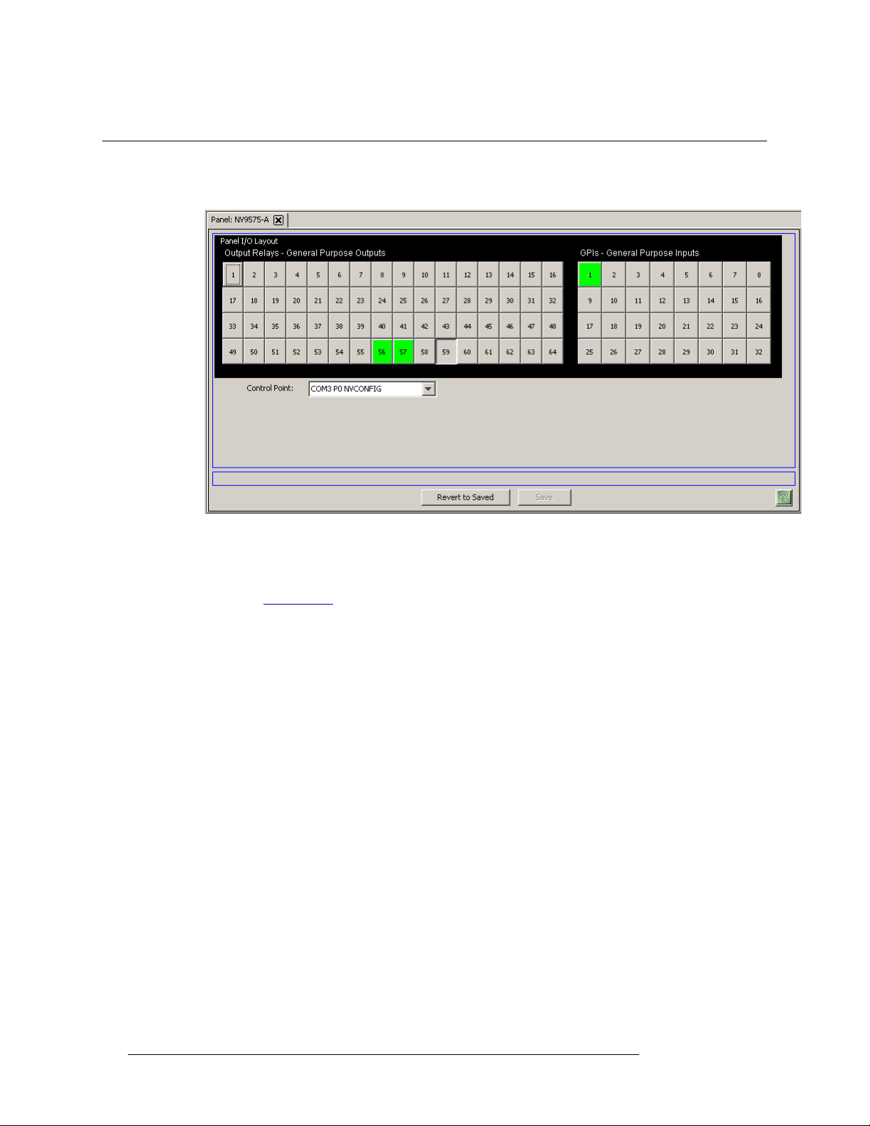
This is the NV9575-VF panel configuration page from NV9000-SE Utilities:
Note: The “buttons” you see on the NV9575-VF page represent connections at the rear of the panel.
The NV9575-VF has no buttons.
Initial setup of the NV9575-VF requires installation and use of the Videoframe configuration software. See Initial Setup
, on page 7, for details.
Regions of the Page
There are 3 regions:
• ‘Revert to Saved’ and ‘Save’ buttons.
These buttons are present on all configuration pages in NV9000-SE Utilities. Press ‘Save’ at
any time to commit changes to the panel configuration. The ‘Save’ button is disabled (grayed
out) if there are no changes to save.
Press ‘Revert to Saved’ if you want to discard recent changes that you have made.
• A graphic representation of the NV9575-VF connectors.
On the right side are 32 button images that represent the 32 optically isolated inputs. On the left
side of the panel are 64 button images representing the 64 relay outputs. Click on a button to
assign a function to its associated input or output.
An input can trigger a salvo.
A relay closure occurs based on Boolean expressions defined for the output. The expression can
reflect (1) the occurrence of a particular source switched to a particular destination, on a particular level, (2) output port status, and (3) input transition.
2 Rev 1.1 • 25 Nov 14
Page 3
1. NV9575-VF
Configuration
A button appears pressed (like button 59 in the illustration above) when you are assigning a
function to it. Buttons that have been assigned functions appear green (like buttons 56 and 57
above).
• A drop-down menu in which to select a control point for the NV9575-VF.
The control point is one you will have created for the NV9575-VF. See Initial Setup
for details.
Button Definitions
There are two types of buttons in the configuration page: outputs and inputs.
Outputs
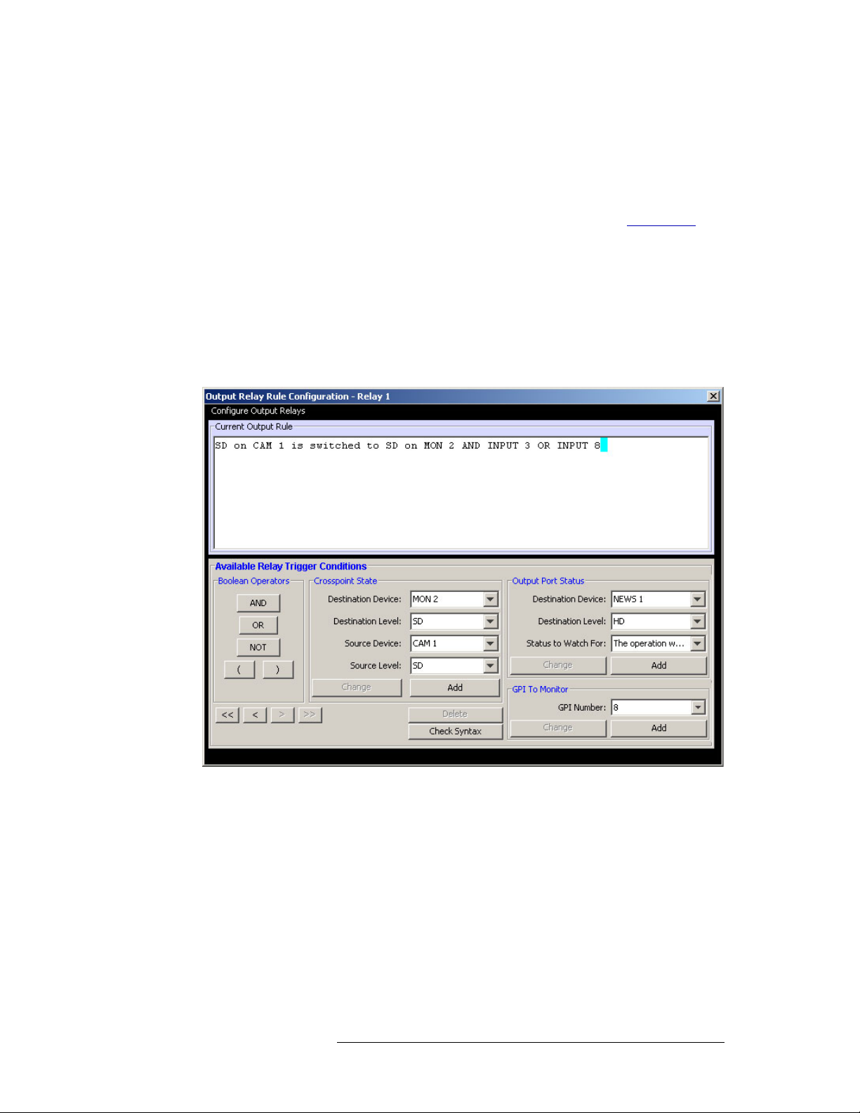
Clicking an output button (one of 64 on the left) displays a “Relay Rule” dialog:
on page 7
In this dialog, you enter a Boolean expression involving sources, destinations, port status, and GPI
status. This sample shows one such Boolean expression.
Boolean expressions comprise terms and operators. The operators include those indicated on the
left:
AND, OR, and NOT. Expressions can be parenthesized to control the order of evaluation. Operator
precedence is normally
parentheses are evaluated before outer parentheses.
Terms (i.e., operands) are generated by choosing entries in the other fields and clicking ADD. The
example shows the following:
Dest. Device:
Source Device: CAM1 Source Level: SD
NV9575-VF Tally Interface • User’s Guide 3
NOT > AND > OR. All parenthesized expressions are evaluated first; nested
MON2 Dest. Level: SD
Page 4

1. NV9575-VF
Configuration
Choosing these items (and clicking ADD) produces the Boolean expression:
In the preceding illustration, that expression is ANDed with another expression
The relay chosen (relay 1) will transition when the entire expression is true. That is, when the
switch occurs and either of the inputs (3 or 8) transitions from off to on.
(To allow a relay to switch when an input transitions from on to off, precede the input term by
“NOT.” For example, the expression
will evaluate true either when input 3 goes from off to on or when input 8 goes from on to off.)
You can also include one or more expressions regarding the state of output ports. You must choose
a entry in the drop-down menu. These are the choices:
Choosing ‘Used as broadcast slave’,
which you can combine with other expressions as you require.
SD on CAM1 is switched to SD on MON2
INPUT 3 OR INPUT 8
INPUT 3 OR NOT INPUT 8
The operation was successful
Destination port locked
Destination port protected
Router offline / unavailable
No tieline available
Used as master point to point
Used as master without responses
Used as broadcast master
Used as slave point to point
Used as slave without responses
Used as Broadcast Slave
VTR3, and CTRL for output port status produces the proposition
CTRL on VTR3 has status of ‘Used as broadcast slave.’
Four arrow buttons at the lower left corner of the relay dialog allow you to traverse the expression
you are building:
The left double arrows highlights the first term or operator in the expression. The right double
arrow positions you at the very end of the expression where you may add more items.
The single arrows select and highlight the previous or next terms, operators, or spaces between
terms and operators. If you wish to change a term, you may highlight it, reconstruct the term in the
appropriate entry fields, and click the Change button to effect the change.
Using the arrows is the only way to position between two items or at the end of the expression. You
can double-click a term or an operator to select it directly.
You can click “Check Syntax” to evaluate the syntax of your complete expression. Generally, an
syntax error will have occurred because you forgot an operator between terms or you have an extra
operator at the end.
You can click “Delete” to delete a selected term or operator.
4 Rev 1.1 • 25 Nov 14
Page 5

This is a brief summary of the Boolean operators:
A
RESET
T
VIDEOFRAME SYSTEMS
GRASS VALLEY, CA
ETHERNET
RT
LC
J1 J2 J3 J4 J5 J6
CONSOLEREMOTE
12VDC-2.5A
MADE IN USA
B
R
T
R
J1: Outputs
1–16
J2: Outputs
17–32
J3: Inputs
1–16
J4: Outputs
33–48
J5: Outputs
49–64
J6: Inputs
17–32
Remote Console
Power
Ethernet
Reset
1. NV9575-VF
Connections
All operands evaluate either
TRUE or FALSE.
AND = true if ALL terms are true; false if ANY term is false.
OR = false if ALL terms are false; true if ANY term is true.
NOT = true if term is false; false if term is true (i.e., negation).
Inputs
Clicking an input button (one of 32 on the right) displays this dialog:
An event is signalled when a transition occurs on the input from on to off or from off to on. You can
configure the NV9575-VF to recognize either occurrence on any of the 32 inputs, and specify the
salvo to execute at either occurrence or both.
Note that you can also include one or more input transitions in relay output expressions.
Important Be sure to ‘Save’ frequently.
Connections
This is the rear of the tally interface:
The NV9575-VF has 6 DB25 connectors on its rear panel
— J1 through J6. J1, J2, J4, and J5 pro-
vide connections for the 64 relay outputs, 16 per connector, with 8 pins common. J3 and J6 provide
connections for the 32 inputs, also 16 per connector with 8 pins common.
It also has 2 power connectors, an RJ-45 Ethernet port, two DE9s (remote and console). The DE9s
and the Ethernet port have LED activity indicators.
The ‘remote’ connector is not used. The console connector is used briefly to assign the NV9575-VF
an IP address. The Ethernet connector is the port through which the NV9000 system communicates
with the NV9575-VF.
NV9575-VF Tally Interface • User’s Guide 5
Page 6

1. NV9575-VF
1
1425
13, Relay 1
13
25, Relay 2
24, Relay 4
23, Relay 6
22, Relay 8
12, Relay 3
11, Relay 5
10, Relay 7
15, 14 Common for relays 916
9, 8 Common for relays 18
3, 2 Common for relays 916
4, Relay 15
5, Relay 13
6, Relay 11
7, Relay 9
21, 20 Common for relays 18
16, Relay 16
17, Relay 14
18, Relay 12
19, Relay 10
J1: Relays 1–16
J2: Relays 17–32
J4: Relays 33–48
J5: Relays 49–64
1
1425
12, GPI 2
13
25, GPI 1
24, GPI 3
23, GPI 5
22, GPI 7
11, GPI 4
10, GPI 6
9, GPI 8
15, 14 Common for GPIs 916
8, 7 Common for GPIs 18
2, 1 Common for GPIs 916
3, GPI 16
4, GPI 14
5, GPI 12
6, GPI 10
21, 20 Common for GPIs 18
16, GPI 15
17, GPI 13
18, GPI 11
19, GPI 9
J3: GPIs 1–16
J6: GPIs 17–32
Connections
Output Connectors
The 4 output connectors all have the same format, but for consecutive sets of outputs:
Input Connectors
The 2 input connectors have the same format, but for consecutive sets of inputs:
6 Rev 1.1 • 25 Nov 14
Power Supplies
The tally expander can operate with either one or two external power supplies.
The power supplies connect to the tally expander with 2.5mm connectors. The power supply con-
nectors screw securely onto the tally expander’s connectors. The LEDs on the front of the tally
expander indicate whether power is present at either of the receptacles.
You can use two power supplies for redundancy. The secondary supply will take over without inter-
ruption in event of a failure. (A redundant supply is optional.)
We recommend using the furnished power supply. However, in an emergency, any well-regulated
12V 2.5A supply can be used. A power supply connected to the tally expander must have a long-
shaft bayonet connector with a 2.5mm center pin. Many power supplies have 2.1mm center pins
These do not fit the receptacles on the frame.
Console Port
Use the console port to load an IP address into the NV9575-VF (using Videoframe’s software).
This port connects to a COM port of your PC. A DE9 female null modem serial cable is supplied
with the tally expander. (You can purchase a replacement at any computer store.)
Page 7

Remote Port
This port is not used.
Ethernet Port
The tally expander has one 10baseT Ethernet port (an RJ-45 connection). This port connects to the
(Ethernet switch/hub of) the NV9000 panel and router network.
Reset Button
The reset button, near the power connectors, is recessed. You will need a pencil or small screw-
driver to press the reset button.
Initial Setup
Before you can configure or use the NV9575-VF, you must perform two setup tasks, first in
NV9000-SE Utilities, the second in the Videoframe configuration software. The NV9575-VF must
be connected to the NV9000’s panel and router network. Determine an IP address for the NV9575VF. You will enter the IP address in NV9000-SE Utilities and the Videoframe configuration software.
1. NV9575-VF
Initial Setup
After performing these initial steps, connect the NV9575-VF to (the Ethernet switch/hub of) the
NV9000’s panel and router network.
In NV9000-SE Utilities
Follow these steps (guidelines) to create an external interface definition in your current NV9000
configuration:
1 Open the configuration in NV9000-SE Utilities.
2 Go to the Tasks > Add External Interfaces page. Enter a name for the interface. Specify ‘NV
Ethernet interface’ for the protocol, and choose -New- for the control point.
NV9575-VF Tally Interface • User’s Guide 7
Page 8

1. NV9575-VF
Initial Setup
Leave the ‘Params’ field blank. Click ‘Add & Edit’. The ‘External Interface Detail’ page
appears:
Enter the IP address you chose for the NV9575-VF on this page. Click ‘Save.’
The NV9000 control point for the NV9575-VF uses this IP address. The ‘Control Points’ table
of NV9000-SE Utilities will include it. The ‘External Interfaces’ table will include this interface.
In Videoframe Configuration Software
If you have not yet done so, install the Videoframe configuration software. To do so, load the
Videoframe installation disk in your CD drive. Open the CD at the top directory level.
Then, double-click Videoframe Configuration V1.5.exe to launch the program installer. Go through
the installation steps as they occur, clicking ‘Next’ to advance to the next step. The installation
takes a few seconds.
Connect a COM port of your PC to the console port of the NV9575-VF using a null-modem cable.
The serial settings must be 9600 Baud, 8N1, no echo, and no flow control (if you need to adjust the
settings in the Videoframe software).
Follow these steps (guidelines) to set the IP address in your NV9575-VF:
3 Launch the configuration software. From the Windows Start menu, that is (by default)
Start > Programs > Videoframe > VideoframeConfiguration
The Videoframe Configuration window appears:
8 Rev 1.1 • 25 Nov 14
Page 9

1. NV9575-VF
Click
Initial Setup
4 Choose ‘Console (CMD)’ from the ‘Window’ menu to open the “console”:
Click the ‘Serial Connection’ button to make it turn green. This activates serial communication.
5 Choose ‘Download and Save Config File...’ from the Command menu:
This command copies the configuration from the NV9575-VF to a file in your PC. The file contents appears in the Videoframe Configuration window.
Modify the configuration, in this window, as required. In particular, specify the IP address of
the NV9575-VF and ensure that “CONORTMO”
— is 10,000 or more.
onds
— connection override timeout, in millisec-
You may ignore “DEFGATE.” The “NETMASK” must be 255.255.255.0.
Choose ‘Save’ from the ‘File’ menu to save the configuration file.
NV9575-VF Tally Interface • User’s Guide 9
Page 10

1. NV9575-VF
Specifications
6 Choose ‘Upload Config File...’ from the ‘Command’ menu:
This copies the modified configuration back to the NV9575-VF. The console window displays
a confirmation.
Specifications
You might now choose ‘Print Current Config to Console’ from the ‘Command’ menu. This
allows you to verify visually that your configuration is now in the NV9575-VF.
That is all that is required of the Videoframe Configuration software. You may now proceed to
NV9000-SE Utilities to configure the NV9575-VF relays and inputs.
Power Supply: External 12VDC at 2.5A.
Dimensions: 19.0″ × 10.0″ × 1.75″.
Weight: 6.0lb.
Power: ≤ 15W (with one 12V external supply).
Relay current: ≤ 0.5A
10 Rev 1.1 • 25 Nov 14
Page 11

Notes
1. NV9575-VF
Notes
Technical Support
Grass Valley has made every effort to ensure that the equipment you receive is in perfect working
order and that the equipment fits your needs. In the event that problems arise that you cannot
resolve, or if there are any questions regarding this equipment or information about other products
manufactured by Grass Valley, please contact your local representative or contact Grass Valley
directly through one of the appropriate means listed here.
• Main telephone: 514-333-1772
Fax: 514-333-9828
In the Americas, call toll-free: +1-800-547-8949 or +1 530 478 4148 (9 am to 9 pm EST)
In Europe, the Middle East, Africa, or the UK, call +44 118 952 3444 (9 am to 6 pm, GMT)
For playout automation, call +44 870 500 4350 (9 am to 5:30 pm, GMT)
In France, call +33 1 55 86 87 88 (9 am to 5 pm, GMT + 1)
In Asia, call +852-2539-6987 (9:30 am to 5 pm, GMT + 8)
In China, call +86-10-5873-1814 (9:30 am to 5 pm, GMT + 8)
In Malaysia, call +60 3 2247 1808
•E-Mail:
In the Americas, support@grass valley.com
In Europe, the Middle East, Africa, or the UK, eurotech@grass valley.com
For playout automation, automationsupport@grass valley.com
In France, eurotech@grass valley.com
In Asia, asiatech@grass valley.com
In China, asiatech@grass valley.com
In Malaysia, asiatech@grass valley.com
•Mail
Grass Valley
3499 Douglas B. Floreani
Montreal, Quebec
Canada H4S 2C6
Note Return Material Authorization (RMA) required for all returns.
Videoframe, Inc.
The NV9575-VF tally interface and its configuration software are products of
Vid e oframe, Inc.
101 Providence Mine Road, Suite 103
Nevada City CA 95959
USA
530-477-2000
www.videoframesystems.com
You may obtain additional information from Videoframe. “Videoframe” and “Tally Expander” are
trademarks of Videoframe, Inc.
NV9575-VF Tally Interface • User’s Guide 11
Page 12

1. NV9575-VF
Notes
12 Rev 1.1 • 25 Nov 14
 Loading...