

Page 1
NV9000-SE
Utilities
User’s Guide
Miranda Technologies Inc.
3499 Douglas B. Floreani
Montreal, Quebec
Canada H4S 2C6
Page 2

NV9000-SE Utilities — User’s Guide
• Revision: 3.0
• Software Version: 6.0.0
• Part Number: UG0007-05
• Copyright: © 2010 Miranda Technologies. All rights reserved.
• No part of this manual may be reproduced in any form by photocopy, microfilm, xerography or
any other means, or incorporated into any information retrieval system, electronic or mechanical, without the written permission of Miranda Technologies, Inc.
• The information contained in this manual is subject to change without notice or obligation.
• All title and copyrights as well as trade secret, patent and other proprietary rights in and to the
Software Product (including but not limited to any images, photographs, animations, video,
audio, music, test, and “applets” incorporated into the Software Product), the accompanying
printed materials, and any copies of the Software Product, are owned by Miranda Technologies,
Inc. The Software Product is protected by copyright laws and international treaty provisions.
Customer shall not copy the printed materials accompanying the software product.
Notice
The software contains proprietary information of Miranda Technologies, Inc. It is provided under a
license agreement containing restrictions on use and disclosure and is also protected by copyright
law. Reverse engineering of the software is prohibited.
Due to continued product development, the accuracy of the information in this document may
change without notice. The information and intellectual property contained herein is confidential
between Miranda and the client and remains the exclusive property of Miranda. If you find any
problems in the documentation, please report them to us in writing. Miranda does not warrant that
this document is error-free.
FCC Statement
This equipment has been tested and found to comply with the limits for a Class A digital device,
pursuant to part 15 of the FCC Rules. These limits are designed to provide reasonable protection
against harmful interference when the equipment is operated in a commercial environment. This
equipment generates, uses, and can radiate radio frequency energy and, if not installed and used in
accordance with the instruction manual, may cause harmful interference to radio communications.
Operation of this equipment in a residential area is likely to cause harmful interference in which
case the user will be required to correct the interference at his own expense.
Declaration of Conformance (CE)
All of the equipment described in this manual has been designed to conform with the required
safety and emissions standards of the European Community. Products tested and verified to meet
these standards are marked as required by law with the CE mark. (See Symbols and Their Mean-
ings on page v.)
ii Rev 3.0 • 18 Aug 10
Page 3

When shipped into member countries of the European Community, this equipment is accompanied
by authentic copies of original Declarations of Conformance on file in Miranda GVD offices in
Grass Valley, California USA.
Trademarks
Miranda is a registered trademark of Miranda Technologies, Inc.
Brand and product names mentioned in this manual may be trademarks, registered trademarks or
copyrights of their respective holders. All brand and product names mentioned in this manual serve
as comments or examples and are not to be understood as advertising for the products or their manufactures.
Software License Agreement and Warranty Information
Contact Miranda for details on the software license agreement and product warranty.
Technical Support Contact Information
Miranda has made every effort to ensure that the equipment you receive is in perfect working order
and that the equipment fits your needs. In the event that problems arise that you cannot resolve, or
if there are any questions regarding this equipment or information about other products manufactured by Miranda, please contact your local representative or contact Miranda directly through one
of the appropriate means listed here.
• Main telephone: 530-265-1000 (9 am to 9 pm PST)
Fax: 530-265-1021
In the Americas, call toll-free: +1-800-224-7882 (9 am to 9 pm EST)
In Europe, the Middle East, African or the UK, call +44 (0) 1491 820222 (9 am to 6 pm, GMT)
In France, call +33 1 55 86 87 88 (9 am to 5 pm, GMT + 1)
In Asia, call +852-2539-6987 (9 am to 5 pm, GMT + 8)
In China, call +86-10-5873-1814
• Emergency after hours: toll-free: +1-800-224-7882
Tel: +1-514-333-1772
•E-Mail:
In the Americas, support@miranda.com
In Europe, the Middle East, African or the UK, eurotech@miranda.com
In France, eurotech@miranda.com
In Asia, asiatech@miranda.com
In China, asiatech@miranda.com
• Website: http://www.miranda.com
• Mail Shipping
Miranda GVD Miranda GVD
P.O. Box 1658 125 Crown Point Court
Nevada City, CA 95959, USA Grass Valley, CA 95945, USA
Note Return Material Authorization (RMA) required for all returns.
NV9000-SE Utilities • User’s Guide iii
Page 4
Change History
The table below lists the changes to the NV9000-SE User’s Guide.
• User’s Guide Part # UG0007-05
• Software version: 6.0.0
Rev Date ECO Description Approved By
1.0 28 Aug 06 — Initial Release D.Cox
2.0 17 Oct 08 14426 Created online help system. Updated to match product
2.1 18 Feb 09 15573 Updates PG, JE, DM, et
2.2 31 Mar 09 15703 Format change. D.Cox
2.3 12 Jan 10 16272 Added NV9642, dynamic configuration updates, serial
3.0 18 Aug 10 17186 Updated for versions 5.3.x, 5.4.x and 6.0.0; tieline
updates.
control of SMS7000 (and bridges), global navigation
buttons, Klotz serial protocol, remote machine control
routing.
groups; import and export data; changes to system
management; name sets
PG, JE, DM, et
al
al
DM, KL, MN
DEM
D. Galbraith
I. Godfrey
K. Lyons
iv Rev 3.0 • 18 Aug 10
Page 5
Important Safeguards and Notices
This section provides important safety guidelines for operators and service personnel. Specific
warnings and cautions appear throughout the manual where they apply. Please read and follow this
important information, especially those instructions related to the risk of electric shock or injury to
persons.
Warning
Any instructions in this manual that require opening the equipment cover or
enclosure are for use by qualified service personnel only. To reduce the risk of
electric shock, do not perform any service other than that contained in the operating instructions unless you are qualified to do so.
Symbols and Their Meanings
The lightning flash with arrowhead symbol within an equilateral triangle alerts the user to the presence of dangerous voltages within the product’s enclosure that may be of sufficient magnitude to
constitute a risk of electric shock to persons.
The exclamation point within an equilateral triangle alerts the user to the presence of important
operating and maintenance/service instructions.
The Ground symbol represents a protective grounding terminal. Such a terminal must be connected
to earth ground prior to making any other connections to the equipment.
The fuse symbol indicates that the fuse referenced in the text must be replaced with one having the
ratings indicated.
The presence of this symbol in or on Miranda equipment means that it has been designed, tested
and certified as complying with applicable Underwriter’s Laboratory (USA) regulations and recommendations.
The presence of this symbol in or on Miranda equipment means that it has been designed, tested
and certified as essentially complying with all applicable European Union (CE) regulations and
recommendations.
NV9000-SE Utilities • User’s Guide v
Page 6

General Warnings
A warning indicates a possible hazard to personnel which may cause injury or death. Observe the
following general warnings when using or working on this equipment:
• Heed all warnings on the unit and in the operating instructions.
• Do not use this equipment in or near water.
• This equipment is grounded through the grounding conductor of the power cord. To avoid electrical shock, plug the power cord into a properly wired receptacle before connecting the equipment inputs or outputs.
• Route power cords and other cables so they are not likely to be damaged.
• Disconnect power before cleaning the equipment. Do not use liquid or aerosol cleaners; use
only a damp cloth.
• Dangerous voltages may exist at several points in this equipment. To avoid injury, do not touch
exposed connections and components while power is on.
• Do not wear rings or wristwatches when troubleshooting high current circuits such as the power
supplies.
• To avoid fire hazard, use only the specified fuse(s) with the correct type number, voltage and
current ratings as referenced in the appropriate locations in the service instructions or on the
equipment. Always refer fuse replacements to qualified service personnel.
• To avoid explosion, do not operate this equipment in an explosive atmosphere.
• Have qualified service personnel perform safety checks after any service.
General Cautions
A caution indicates a possible hazard to equipment that could result in equipment damage. Observe
the following cautions when operating or working on this equipment:
• When installing this equipment, do not attach the power cord to building surfaces.
• To prevent damage to equipment when replacing fuses, locate and correct the problem that
caused the fuse to blow before re-applying power.
• Use only the specified replacement parts.
• Follow static precautions at all times when handling this equipment.
• This product should only be powered as described in the manual. To prevent equipment damage, select the proper line voltage on the power supply(ies) as described in the installation documentation.
• To prevent damage to the equipment, read the instructions in the equipment manual for proper
input voltage range selection.
• Some products include a backup battery. There is a risk of explosion if the battery is replaced by
a battery of an incorrect type. Dispose of batteries according to instructions.
• Products that have (1) no on/off switch and (2) use an external power supply must be installed
in proximity to a main power output that is easily accessible.
vi Rev 3.0 • 18 Aug 10
Page 7

Table of Contents
Chapter 1 Getting Started . . . . . . . . . . . . . . . . . . . . . . . . . . . . . . . . . . . . . . . . . . . . . . . . . . . . . . . . . . . . 1
What is New. . . . . . . . . . . . . . . . . . . . . . . . . . . . . . . . . . . . . . . . . . . . . . . . . . . . . . . . . . . . . . . . . . . 1
Tielines. . . . . . . . . . . . . . . . . . . . . . . . . . . . . . . . . . . . . . . . . . . . . . . . . . . . . . . . . . . . . . . . . . . 1
Dynamic Configuration Updates . . . . . . . . . . . . . . . . . . . . . . . . . . . . . . . . . . . . . . . . . . . . . . . 1
NV9462 Control Panel. . . . . . . . . . . . . . . . . . . . . . . . . . . . . . . . . . . . . . . . . . . . . . . . . . . . . . . 2
SMS7000 . . . . . . . . . . . . . . . . . . . . . . . . . . . . . . . . . . . . . . . . . . . . . . . . . . . . . . . . . . . . . . . . . 2
Sony ROT-16 SBus . . . . . . . . . . . . . . . . . . . . . . . . . . . . . . . . . . . . . . . . . . . . . . . . . . . . . . . . . 2
Global Navigation Buttons. . . . . . . . . . . . . . . . . . . . . . . . . . . . . . . . . . . . . . . . . . . . . . . . . . . . 2
Klotz Serial Protocol . . . . . . . . . . . . . . . . . . . . . . . . . . . . . . . . . . . . . . . . . . . . . . . . . . . . . . . . 2
NV9000-SE Write Timing . . . . . . . . . . . . . . . . . . . . . . . . . . . . . . . . . . . . . . . . . . . . . . . . . . . . 3
Remote Networked Control Systems . . . . . . . . . . . . . . . . . . . . . . . . . . . . . . . . . . . . . . . . . . . . 3
What to Do and When to Do it. . . . . . . . . . . . . . . . . . . . . . . . . . . . . . . . . . . . . . . . . . . . . . . . . . . . . 3
Configuration Steps . . . . . . . . . . . . . . . . . . . . . . . . . . . . . . . . . . . . . . . . . . . . . . . . . . . . . . . . . 3
An Overview . . . . . . . . . . . . . . . . . . . . . . . . . . . . . . . . . . . . . . . . . . . . . . . . . . . . . . . . . . . . . . . . . . 5
Understanding the NV9000-SE Concept . . . . . . . . . . . . . . . . . . . . . . . . . . . . . . . . . . . . . . . . . 5
Configuration . . . . . . . . . . . . . . . . . . . . . . . . . . . . . . . . . . . . . . . . . . . . . . . . . . . . . . . . . . 5
Organizing Sources and Destinations . . . . . . . . . . . . . . . . . . . . . . . . . . . . . . . . . . . . . . . 6
Control Panels . . . . . . . . . . . . . . . . . . . . . . . . . . . . . . . . . . . . . . . . . . . . . . . . . . . . . . . . . 6
Chapter 2 Using the Interface . . . . . . . . . . . . . . . . . . . . . . . . . . . . . . . . . . . . . . . . . . . . . . . . . . . . . . . . 7
The SE Utilities Window . . . . . . . . . . . . . . . . . . . . . . . . . . . . . . . . . . . . . . . . . . . . . . . . . . . . . . . . . 8
Navigation Area . . . . . . . . . . . . . . . . . . . . . . . . . . . . . . . . . . . . . . . . . . . . . . . . . . . . . . . . . . . . 8
Work Area . . . . . . . . . . . . . . . . . . . . . . . . . . . . . . . . . . . . . . . . . . . . . . . . . . . . . . . . . . . . . . . . 8
Common Commands . . . . . . . . . . . . . . . . . . . . . . . . . . . . . . . . . . . . . . . . . . . . . . . . . . . . 9
Tabs . . . . . . . . . . . . . . . . . . . . . . . . . . . . . . . . . . . . . . . . . . . . . . . . . . . . . . . . . . . . . . . . . 9
Tables . . . . . . . . . . . . . . . . . . . . . . . . . . . . . . . . . . . . . . . . . . . . . . . . . . . . . . . . . . . . . . . . 9
Entering Data . . . . . . . . . . . . . . . . . . . . . . . . . . . . . . . . . . . . . . . . . . . . . . . . . . . . . . . . . . 9
Menu Bar . . . . . . . . . . . . . . . . . . . . . . . . . . . . . . . . . . . . . . . . . . . . . . . . . . . . . . . . . . . . . . . . . 9
Filters . . . . . . . . . . . . . . . . . . . . . . . . . . . . . . . . . . . . . . . . . . . . . . . . . . . . . . . . . . . . . . . . . . . 10
Shortcuts. . . . . . . . . . . . . . . . . . . . . . . . . . . . . . . . . . . . . . . . . . . . . . . . . . . . . . . . . . . . . . . . . . . . . 10
Double-click Option. . . . . . . . . . . . . . . . . . . . . . . . . . . . . . . . . . . . . . . . . . . . . . . . . . . . . . . . 10
File Menu . . . . . . . . . . . . . . . . . . . . . . . . . . . . . . . . . . . . . . . . . . . . . . . . . . . . . . . . . . . . . . . . 10
Control Panel Keyboard. . . . . . . . . . . . . . . . . . . . . . . . . . . . . . . . . . . . . . . . . . . . . . . . . 11
Keyboard Shortcut Best Practices . . . . . . . . . . . . . . . . . . . . . . . . . . . . . . . . . . . . . . . . . 11
Exiting Level Mode . . . . . . . . . . . . . . . . . . . . . . . . . . . . . . . . . . . . . . . . . . . . . . . . . . . . 12
Launching and Exiting the Application . . . . . . . . . . . . . . . . . . . . . . . . . . . . . . . . . . . . . . . . . . . . . 12
Chapter 3 Installation . . . . . . . . . . . . . . . . . . . . . . . . . . . . . . . . . . . . . . . . . . . . . . . . . . . . . . . . . . . . . . . 13
Adding to a Network . . . . . . . . . . . . . . . . . . . . . . . . . . . . . . . . . . . . . . . . . . . . . . . . . . . . . . . . . . . 13
Installing the Application . . . . . . . . . . . . . . . . . . . . . . . . . . . . . . . . . . . . . . . . . . . . . . . . . . . . . . . . 14
How to Install the NV9000-SE Application . . . . . . . . . . . . . . . . . . . . . . . . . . . . . . . . . . . . . 14
NV9000-SE Utilities • User’s Guide vii
Page 8

Table of Contents
Chapter 4 Configurations . . . . . . . . . . . . . . . . . . . . . . . . . . . . . . . . . . . . . . . . . . . . . . . . . . . . . . . . . . . 17
Note About Networking . . . . . . . . . . . . . . . . . . . . . . . . . . . . . . . . . . . . . . . . . . . . . . . . . . . . . . . . . 17
Implementing Configuration Changes . . . . . . . . . . . . . . . . . . . . . . . . . . . . . . . . . . . . . . . . . . . . . . 17
How to Implement Configuration Changes . . . . . . . . . . . . . . . . . . . . . . . . . . . . . . . . . . . . . . 18
Working With Configuration Files . . . . . . . . . . . . . . . . . . . . . . . . . . . . . . . . . . . . . . . . . . . . . . . . 19
Opening a Configuration . . . . . . . . . . . . . . . . . . . . . . . . . . . . . . . . . . . . . . . . . . . . . . . . . . . . 19
How to Open a Configuration from a Directory Location . . . . . . . . . . . . . . . . . . . . . . . 19
Creating or Changing a Configuration File . . . . . . . . . . . . . . . . . . . . . . . . . . . . . . . . . . . . . . 20
How to Create a New “Empty” Configuration File . . . . . . . . . . . . . . . . . . . . . . . . . . . . . . . . 20
How to Associate a Different Configuration File with a Control Panel . . . . . . . . . . . . 20
Saving Configuration Changes . . . . . . . . . . . . . . . . . . . . . . . . . . . . . . . . . . . . . . . . . . . . . . . 21
Deleting or Renaming Configuration Folders . . . . . . . . . . . . . . . . . . . . . . . . . . . . . . . . . . . . 22
Adding Computers to Existing EC9700 or EC9710 Configurations . . . . . . . . . . . . . . . . . . . 22
How to Add an EC9700/EC9710 Control Panel to an Existing Configuration. . . . . . . 22
Creating, Updating and Deleting Configuration File Pathnames . . . . . . . . . . . . . . . . . . . . . 24
How to Update the Configuration File Pathname for an EC9700 or EC9710. . . . . . . . 24
How to Create a New Configuration File Pathname . . . . . . . . . . . . . . . . . . . . . . . . . . . 26
How to Update a Configuration File Pathname . . . . . . . . . . . . . . . . . . . . . . . . . . . . . . . 26
How to Delete a Configuration File Pathname . . . . . . . . . . . . . . . . . . . . . . . . . . . . . . . 27
Importing and Exporting Configurations . . . . . . . . . . . . . . . . . . . . . . . . . . . . . . . . . . . . . . . . . . . . 28
How to Import from a Compressed Configuration File. . . . . . . . . . . . . . . . . . . . . . . . . . . . . 29
How to Export to a Compressed File . . . . . . . . . . . . . . . . . . . . . . . . . . . . . . . . . . . . . . . 30
How to Import a Non-NV9000-SE Configuration. . . . . . . . . . . . . . . . . . . . . . . . . . . . . 30
Analyzing Configurations . . . . . . . . . . . . . . . . . . . . . . . . . . . . . . . . . . . . . . . . . . . . . . . . . . . . . . . 30
How to Analyze a Configuration . . . . . . . . . . . . . . . . . . . . . . . . . . . . . . . . . . . . . . . . . . . . . . 31
Chapter 5 System Management . . . . . . . . . . . . . . . . . . . . . . . . . . . . . . . . . . . . . . . . . . . . . . . . . . . . . 33
About System Controllers . . . . . . . . . . . . . . . . . . . . . . . . . . . . . . . . . . . . . . . . . . . . . . . . . . . . . . . 33
IP Addresses. . . . . . . . . . . . . . . . . . . . . . . . . . . . . . . . . . . . . . . . . . . . . . . . . . . . . . . . . . . . . . 33
Logs . . . . . . . . . . . . . . . . . . . . . . . . . . . . . . . . . . . . . . . . . . . . . . . . . . . . . . . . . . . . . . . . 34
Managing System Controllers . . . . . . . . . . . . . . . . . . . . . . . . . . . . . . . . . . . . . . . . . . . . . . . . . . . . 35
Adding System Controllers . . . . . . . . . . . . . . . . . . . . . . . . . . . . . . . . . . . . . . . . . . . . . . . . . . 36
How to Add a System Controller . . . . . . . . . . . . . . . . . . . . . . . . . . . . . . . . . . . . . . . . . . 37
Starting, Stopping or Shutting Down . . . . . . . . . . . . . . . . . . . . . . . . . . . . . . . . . . . . . . . . . . . 37
How to Start, Stop or Shut Down a System Controller . . . . . . . . . . . . . . . . . . . . . . . . . 38
Rebooting a System Controller . . . . . . . . . . . . . . . . . . . . . . . . . . . . . . . . . . . . . . . . . . . . . . . 38
How to Reboot a System Controller . . . . . . . . . . . . . . . . . . . . . . . . . . . . . . . . . . . . . . . 38
Selecting a System Controller to “Ignore”. . . . . . . . . . . . . . . . . . . . . . . . . . . . . . . . . . . . . . . 38
How to Ignore a System Controller . . . . . . . . . . . . . . . . . . . . . . . . . . . . . . . . . . . . . . . . 38
Removing a System Controller . . . . . . . . . . . . . . . . . . . . . . . . . . . . . . . . . . . . . . . . . . . . . . . 38
How to Remove a System Controller . . . . . . . . . . . . . . . . . . . . . . . . . . . . . . . . . . . . . . 39
Managing System Controller Communication . . . . . . . . . . . . . . . . . . . . . . . . . . . . . . . . . . . . . . . 39
Changing System Controller IP Address or Name . . . . . . . . . . . . . . . . . . . . . . . . . . . . . . . . 39
How to Change IP Address or Name. . . . . . . . . . . . . . . . . . . . . . . . . . . . . . . . . . . . . . . 39
Changing or Viewing DHCP . . . . . . . . . . . . . . . . . . . . . . . . . . . . . . . . . . . . . . . . . . . . . . . . . 40
How to Change or View the DHCP. . . . . . . . . . . . . . . . . . . . . . . . . . . . . . . . . . . . . . . . 40
Changing or Viewing SNMP . . . . . . . . . . . . . . . . . . . . . . . . . . . . . . . . . . . . . . . . . . . . . . . . . 41
How to Change or View the SNMP. . . . . . . . . . . . . . . . . . . . . . . . . . . . . . . . . . . . . . . . 41
Changing or Setting a Virtual IP . . . . . . . . . . . . . . . . . . . . . . . . . . . . . . . . . . . . . . . . . . . . . . 41
How to Change or Set a Virtual IP . . . . . . . . . . . . . . . . . . . . . . . . . . . . . . . . . . . . . . . . 41
Loading and Saving Snapshots . . . . . . . . . . . . . . . . . . . . . . . . . . . . . . . . . . . . . . . . . . . . . . . . . . . 42
How to Save and Load a Snapshot. . . . . . . . . . . . . . . . . . . . . . . . . . . . . . . . . . . . . . . . . . . . . 42
Generating a Difference Report . . . . . . . . . . . . . . . . . . . . . . . . . . . . . . . . . . . . . . . . . . . . . . . . . . . 42
How to Run a Difference Report . . . . . . . . . . . . . . . . . . . . . . . . . . . . . . . . . . . . . . . . . . . . . . 42
viii Rev 3.0 • 25 Mar 10
Page 9

Table of Contents
Managing Host Computers . . . . . . . . . . . . . . . . . . . . . . . . . . . . . . . . . . . . . . . . . . . . . . . . . . . . . . 42
Adding a Host . . . . . . . . . . . . . . . . . . . . . . . . . . . . . . . . . . . . . . . . . . . . . . . . . . . . . . . . . . . . 43
How to Add a Host. . . . . . . . . . . . . . . . . . . . . . . . . . . . . . . . . . . . . . . . . . . . . . . . . . . . . 43
Locating and Viewing Hosts . . . . . . . . . . . . . . . . . . . . . . . . . . . . . . . . . . . . . . . . . . . . . . . . . 44
How to Locate and View Hosts . . . . . . . . . . . . . . . . . . . . . . . . . . . . . . . . . . . . . . . . . . . 44
Updating a Host . . . . . . . . . . . . . . . . . . . . . . . . . . . . . . . . . . . . . . . . . . . . . . . . . . . . . . . . . . . 46
How to Edit Host Information . . . . . . . . . . . . . . . . . . . . . . . . . . . . . . . . . . . . . . . . . . . . 46
Deleting a Host. . . . . . . . . . . . . . . . . . . . . . . . . . . . . . . . . . . . . . . . . . . . . . . . . . . . . . . . . . . . 47
How to Delete a Host . . . . . . . . . . . . . . . . . . . . . . . . . . . . . . . . . . . . . . . . . . . . . . . . . . . 48
Managing System Parameters . . . . . . . . . . . . . . . . . . . . . . . . . . . . . . . . . . . . . . . . . . . . . . . . . . . . 48
Adding System Parameters . . . . . . . . . . . . . . . . . . . . . . . . . . . . . . . . . . . . . . . . . . . . . . . . . . 49
How to Add a System Parameter . . . . . . . . . . . . . . . . . . . . . . . . . . . . . . . . . . . . . . . . . . 49
Viewing System Parameters . . . . . . . . . . . . . . . . . . . . . . . . . . . . . . . . . . . . . . . . . . . . . . . . . 49
How to View a System Parameter . . . . . . . . . . . . . . . . . . . . . . . . . . . . . . . . . . . . . . . . . 50
Updating System Parameters . . . . . . . . . . . . . . . . . . . . . . . . . . . . . . . . . . . . . . . . . . . . . . . . . 50
How to Update a System Parameter . . . . . . . . . . . . . . . . . . . . . . . . . . . . . . . . . . . . . . . 50
Deleting a System Parameter . . . . . . . . . . . . . . . . . . . . . . . . . . . . . . . . . . . . . . . . . . . . . . . . . 51
How to Delete a System Parameter . . . . . . . . . . . . . . . . . . . . . . . . . . . . . . . . . . . . . . . . 51
Chapter 6 Importing and Exporting Data . . . . . . . . . . . . . . . . . . . . . . . . . . . . . . . . . . . . . . . . . . . . 53
Importing Data . . . . . . . . . . . . . . . . . . . . . . . . . . . . . . . . . . . . . . . . . . . . . . . . . . . . . . . . . . . . . . . . 53
How to Import Data to a Table . . . . . . . . . . . . . . . . . . . . . . . . . . . . . . . . . . . . . . . . . . . . . . . 54
Exporting Data . . . . . . . . . . . . . . . . . . . . . . . . . . . . . . . . . . . . . . . . . . . . . . . . . . . . . . . . . . . . . . . . 56
How to Export Data from Tables . . . . . . . . . . . . . . . . . . . . . . . . . . . . . . . . . . . . . . . . . . . . . . 57
How to Export Devices and Physical Connection Data. . . . . . . . . . . . . . . . . . . . . . . . . 58
Chapter 7 Routers . . . . . . . . . . . . . . . . . . . . . . . . . . . . . . . . . . . . . . . . . . . . . . . . . . . . . . . . . . . . . . . . . .61
About Routers . . . . . . . . . . . . . . . . . . . . . . . . . . . . . . . . . . . . . . . . . . . . . . . . . . . . . . . . . . . . . . . . 62
Machine Control Port Routers . . . . . . . . . . . . . . . . . . . . . . . . . . . . . . . . . . . . . . . . . . . . . . . . 63
Adding a Router . . . . . . . . . . . . . . . . . . . . . . . . . . . . . . . . . . . . . . . . . . . . . . . . . . . . . . . . . . . . . . . 63
How to Add a Router Using the ‘Add Router’ Wizard or ‘Routers’ Page . . . . . . . . . . . . . . 64
How to Add a Router Using the ‘Routers’ Table. . . . . . . . . . . . . . . . . . . . . . . . . . . . . . 70
Locating and Viewing Existing Router Details . . . . . . . . . . . . . . . . . . . . . . . . . . . . . . . . . . . . . . . 71
How to Locate and View Existing Router Using the ‘Routers’ Page . . . . . . . . . . . . . . . . . . 71
How to Locate and View Existing Routers Using the ‘Routers’ Table . . . . . . . . . . . . . 75
How to Locate and View Existing Routers Using the ‘Router Controls’ Table . . . . . . 75
Viewing Router Ports . . . . . . . . . . . . . . . . . . . . . . . . . . . . . . . . . . . . . . . . . . . . . . . . . . . . . . . . . . . 77
How to View Router Ports . . . . . . . . . . . . . . . . . . . . . . . . . . . . . . . . . . . . . . . . . . . . . . . . . . . 77
Updating Router Details. . . . . . . . . . . . . . . . . . . . . . . . . . . . . . . . . . . . . . . . . . . . . . . . . . . . . . . . . 78
Changing a Router Name . . . . . . . . . . . . . . . . . . . . . . . . . . . . . . . . . . . . . . . . . . . . . . . . . . . . 79
How to Changes a Router Name Using the ‘Routers’ Page . . . . . . . . . . . . . . . . . . . . . 79
How to Change a Router Name Using the ‘Routers’ Table. . . . . . . . . . . . . . . . . . . . . . 81
Updating a Router Host . . . . . . . . . . . . . . . . . . . . . . . . . . . . . . . . . . . . . . . . . . . . . . . . . . . . . 82
How to update a router host . . . . . . . . . . . . . . . . . . . . . . . . . . . . . . . . . . . . . . . . . . . . . . 82
Updating Router Control Points. . . . . . . . . . . . . . . . . . . . . . . . . . . . . . . . . . . . . . . . . . . . . . . 83
How to Update Router Control Points. . . . . . . . . . . . . . . . . . . . . . . . . . . . . . . . . . . . . . 84
Updating Router Protocol . . . . . . . . . . . . . . . . . . . . . . . . . . . . . . . . . . . . . . . . . . . . . . . . . . . 84
How to Update Router Protocol Information. . . . . . . . . . . . . . . . . . . . . . . . . . . . . . . . . 85
Updating Router Control Mode . . . . . . . . . . . . . . . . . . . . . . . . . . . . . . . . . . . . . . . . . . . . . . . 86
How to update router control mode . . . . . . . . . . . . . . . . . . . . . . . . . . . . . . . . . . . . . . . . 86
Updating Router Physical Levels. . . . . . . . . . . . . . . . . . . . . . . . . . . . . . . . . . . . . . . . . . . . . . 87
How to update router physical levels using the ‘Routers’ page. . . . . . . . . . . . . . . . . . . 87
How to Update Router Physical Levels Using the ‘PhysLevel’ Table . . . . . . . . . . . . . 90
Updating Protects and Locks . . . . . . . . . . . . . . . . . . . . . . . . . . . . . . . . . . . . . . . . . . . . . . . . . 91
How to update router protects and locks using the ‘Routers’ page . . . . . . . . . . . . . . . . 91
How to Update Router Protects and Locks Using the ‘PhysLevel’ Table. . . . . . . . . . . 93
NV9000-SE Utilities • User’s Guide ix
Page 10

Table of Contents
Updating Signal Type (Standard or Machine Control) . . . . . . . . . . . . . . . . . . . . . . . . . . . . . 94
How to Update Router Signal Type (Standard or Machine Control) . . . . . . . . . . . . . . 94
Managing Control Points . . . . . . . . . . . . . . . . . . . . . . . . . . . . . . . . . . . . . . . . . . . . . . . . . . . . . . . . 96
Adding Control Points . . . . . . . . . . . . . . . . . . . . . . . . . . . . . . . . . . . . . . . . . . . . . . . . . . . . . . 96
How to Add Control Points . . . . . . . . . . . . . . . . . . . . . . . . . . . . . . . . . . . . . . . . . . . . . . 96
Viewing Control Points . . . . . . . . . . . . . . . . . . . . . . . . . . . . . . . . . . . . . . . . . . . . . . . . . . . . . 97
How to View Control Points . . . . . . . . . . . . . . . . . . . . . . . . . . . . . . . . . . . . . . . . . . . . . 97
Updating Control Points. . . . . . . . . . . . . . . . . . . . . . . . . . . . . . . . . . . . . . . . . . . . . . . . . . . . . 99
How to Update Control Points . . . . . . . . . . . . . . . . . . . . . . . . . . . . . . . . . . . . . . . . . . . . 99
Deleting Control Points . . . . . . . . . . . . . . . . . . . . . . . . . . . . . . . . . . . . . . . . . . . . . . . . . . . . 100
How to Delete a Control Point . . . . . . . . . . . . . . . . . . . . . . . . . . . . . . . . . . . . . . . . . . . 100
Excluding Crosspoints . . . . . . . . . . . . . . . . . . . . . . . . . . . . . . . . . . . . . . . . . . . . . . . . . . . . . . . . . 101
How to Add a Crosspoint Exclusion . . . . . . . . . . . . . . . . . . . . . . . . . . . . . . . . . . . . . . . . . . 101
How to Update a Crosspoint Exclusion. . . . . . . . . . . . . . . . . . . . . . . . . . . . . . . . . . . . 102
How to Remove a Crosspoint Exclusion . . . . . . . . . . . . . . . . . . . . . . . . . . . . . . . . . . . 103
Managing Virtual Crosspoints . . . . . . . . . . . . . . . . . . . . . . . . . . . . . . . . . . . . . . . . . . . . . . . . . . . 103
How Create a Virtual Crosspoint . . . . . . . . . . . . . . . . . . . . . . . . . . . . . . . . . . . . . . . . . 104
Deleting Routers . . . . . . . . . . . . . . . . . . . . . . . . . . . . . . . . . . . . . . . . . . . . . . . . . . . . . . . . . . . . . 107
How to Delete a Router Using the ‘Routers’ Page . . . . . . . . . . . . . . . . . . . . . . . . . . . . . . . 107
How to Delete a Router Using the ‘Routers’ Table. . . . . . . . . . . . . . . . . . . . . . . . . . . 108
Chapter 8 Level Sets . . . . . . . . . . . . . . . . . . . . . . . . . . . . . . . . . . . . . . . . . . . . . . . . . . . . . . . . . . . . . . .111
About Levels and Level Sets . . . . . . . . . . . . . . . . . . . . . . . . . . . . . . . . . . . . . . . . . . . . . . . . . . . . 112
Physical Levels vs. Virtual Levels . . . . . . . . . . . . . . . . . . . . . . . . . . . . . . . . . . . . . . . . . . . . 112
Control Panel Viewing. . . . . . . . . . . . . . . . . . . . . . . . . . . . . . . . . . . . . . . . . . . . . . . . . 114
Creating a Level Set . . . . . . . . . . . . . . . . . . . . . . . . . . . . . . . . . . . . . . . . . . . . . . . . . . . . . . . . . . . 114
How to Create a Level Set . . . . . . . . . . . . . . . . . . . . . . . . . . . . . . . . . . . . . . . . . . . . . . . . . . 115
How to Add Level Sets Using the ‘Level Sets’ Table . . . . . . . . . . . . . . . . . . . . . . . . . . . . . 118
Locating and Viewing Level Sets . . . . . . . . . . . . . . . . . . . . . . . . . . . . . . . . . . . . . . . . . . . . . . . . 119
How to Locate and View Level Sets Using the ‘Level Sets’ Page . . . . . . . . . . . . . . . . . . . 119
How to Locate and View Level Sets Using the ‘Level Sets’ Table. . . . . . . . . . . . . . . 121
How to Locate Level Sets Using the ‘Level Set Details’ Table . . . . . . . . . . . . . . . . . 122
Locating and Viewing Virtual Levels . . . . . . . . . . . . . . . . . . . . . . . . . . . . . . . . . . . . . . . . . 123
How to Locate and View Virtual Levels Using the ‘Virtual Levels’ Table . . . . . . . . 123
Updating Level Sets . . . . . . . . . . . . . . . . . . . . . . . . . . . . . . . . . . . . . . . . . . . . . . . . . . . . . . . . . . . 124
Updating Level Set Name . . . . . . . . . . . . . . . . . . . . . . . . . . . . . . . . . . . . . . . . . . . . . . . . . . 125
How to Update a Level Set Name Using the ‘Level Sets’ Page . . . . . . . . . . . . . . . . . 125
How to Update a Level Set Name Using the ‘Level Sets’ Table. . . . . . . . . . . . . . . . . 126
Adding Virtual Levels and Removing Virtual Levels . . . . . . . . . . . . . . . . . . . . . . . . . . . . . 127
How to Create and Add Virtual Levels to a Level Set Using the ‘Level Sets’ Page. . 128
How to Add Virtual Levels to a Level Set Using the ‘Level Set Details’ Table . . . . . 131
How to Remove Virtual Levels from a Level Set Using the ‘Level Sets’ Page . . . . . 133
How to Remove Virtual Levels from a Level Set
Using the ‘Level Set Details’ Table. . . . . . . . . . . . . . . . . . . . . . . . . . . . . . . . . . . 134
Creating and Deleting Virtual Levels . . . . . . . . . . . . . . . . . . . . . . . . . . . . . . . . . . . . . . . . . 135
How to Create a Virtual Level Using the ‘Virtual Levels’ Table . . . . . . . . . . . . . . . . 136
How to delete a virtual level using the ‘Virtual Levels’ table . . . . . . . . . . . . . . . . . . . 137
Changing the Physical Level Mapping in a Level Set. . . . . . . . . . . . . . . . . . . . . . . . . . . . . 137
How to Change Physical Levels Associated with a Level Set
Using the ‘Level Sets’ Page . . . . . . . . . . . . . . . . . . . . . . . . . . . . . . . . . . . . . . . . . 138
How to Change Physical Levels Associated with a Level Set. . . . . . . . . . . . . . . . . . . 139
Updating the Free Source Associated with a Level Set . . . . . . . . . . . . . . . . . . . . . . . . . . . . 140
How to Update the Free Source Associated with a Virtual Level . . . . . . . . . . . . . . . . 141
How to Update the Free Source Associated with a Level Set . . . . . . . . . . . . . . . . . . . 142
Updating the Level Set Index Number . . . . . . . . . . . . . . . . . . . . . . . . . . . . . . . . . . . . . . . . 143
How to Update the Level Set Index Number. . . . . . . . . . . . . . . . . . . . . . . . . . . . . . . . 144
x Rev 3.0 • 25 Mar 10
Page 11

Table of Contents
Deleting Level Sets . . . . . . . . . . . . . . . . . . . . . . . . . . . . . . . . . . . . . . . . . . . . . . . . . . . . . . . . . . . 145
How to Delete a Level Set Using the ‘Level Sets’ Page . . . . . . . . . . . . . . . . . . . . . . . . . . . 145
How to Delete a Level Set Using the ‘Level Sets’ Table . . . . . . . . . . . . . . . . . . . . . . 146
How to Delete a Level Set Using the ‘Level Set Details’ Table . . . . . . . . . . . . . . . . . 147
Managing Signal Types and Signal Binding . . . . . . . . . . . . . . . . . . . . . . . . . . . . . . . . . . . . . . . . 148
Adding or Binding Signals. . . . . . . . . . . . . . . . . . . . . . . . . . . . . . . . . . . . . . . . . . . . . . . . . . 149
How to Add a Signal Type. . . . . . . . . . . . . . . . . . . . . . . . . . . . . . . . . . . . . . . . . . . . . . 149
How to Bind a Signal Type to a Virtual Level . . . . . . . . . . . . . . . . . . . . . . . . . . . . . . 150
Viewing Signal Type Information . . . . . . . . . . . . . . . . . . . . . . . . . . . . . . . . . . . . . . . . . . . . 151
How to View a Signal Type. . . . . . . . . . . . . . . . . . . . . . . . . . . . . . . . . . . . . . . . . . . . . 151
How to View a Bound Signal Type and the Virtual Level . . . . . . . . . . . . . . . . . . . . . 152
Updating Signal Types and Signal Binding. . . . . . . . . . . . . . . . . . . . . . . . . . . . . . . . . . . . . 152
How to Update a Signal Type . . . . . . . . . . . . . . . . . . . . . . . . . . . . . . . . . . . . . . . . . . . 153
How to Update a Signal Binding . . . . . . . . . . . . . . . . . . . . . . . . . . . . . . . . . . . . . . . . . 153
Deleting Signal Types and Signal Bindings . . . . . . . . . . . . . . . . . . . . . . . . . . . . . . . . . . . . 154
How to Delete a Signal Type . . . . . . . . . . . . . . . . . . . . . . . . . . . . . . . . . . . . . . . . . . . . 155
How to Delete a Signal Type Binding to a Virtual Level . . . . . . . . . . . . . . . . . . . . . . 155
Chapter 9 Devices . . . . . . . . . . . . . . . . . . . . . . . . . . . . . . . . . . . . . . . . . . . . . . . . . . . . . . . . . . . . . . . . .157
About Devices . . . . . . . . . . . . . . . . . . . . . . . . . . . . . . . . . . . . . . . . . . . . . . . . . . . . . . . . . . . . . . . 158
Level Sets and Devices . . . . . . . . . . . . . . . . . . . . . . . . . . . . . . . . . . . . . . . . . . . . . . . . . . . . 158
Categories. . . . . . . . . . . . . . . . . . . . . . . . . . . . . . . . . . . . . . . . . . . . . . . . . . . . . . . . . . . . . . . 159
Adding a Device. . . . . . . . . . . . . . . . . . . . . . . . . . . . . . . . . . . . . . . . . . . . . . . . . . . . . . . . . . . . . . 159
How to Add a Single Device . . . . . . . . . . . . . . . . . . . . . . . . . . . . . . . . . . . . . . . . . . . . . . . . 160
How to Add a Class of Devices Using the ‘Add Multiple Devices’ Wizard. . . . . . . . 162
How to Add a Single Device Using the ‘Devices’ Table . . . . . . . . . . . . . . . . . . . . . . 167
Locating and Viewing Device Details . . . . . . . . . . . . . . . . . . . . . . . . . . . . . . . . . . . . . . . . . . . . . 167
How to Locate and View Devices Using the ‘Devices’ Page . . . . . . . . . . . . . . . . . . . . . . . 168
How to Locate and View Devices Using the ‘Devices’ Table . . . . . . . . . . . . . . . . . . 170
Updating Devices . . . . . . . . . . . . . . . . . . . . . . . . . . . . . . . . . . . . . . . . . . . . . . . . . . . . . . . . . . . . . 171
Changing a Device Name or Description . . . . . . . . . . . . . . . . . . . . . . . . . . . . . . . . . . . . . . 171
How to Update a Device Name or Description Using the ‘Devices’ Page . . . . . . . . . 171
How to Update a Device Name or Description Using the ‘Devices’ Table. . . . . . . . . 173
Updating the Device’s Assigned Level Set . . . . . . . . . . . . . . . . . . . . . . . . . . . . . . . . . . . . . 174
How to Update Device Level Sets . . . . . . . . . . . . . . . . . . . . . . . . . . . . . . . . . . . . . . . . 174
Adding or Removing an Associated Category. . . . . . . . . . . . . . . . . . . . . . . . . . . . . . . . . . . 175
Updating Input/Output Connection Numbers . . . . . . . . . . . . . . . . . . . . . . . . . . . . . . . . . . . 176
How to Update I/O Connection Numbers . . . . . . . . . . . . . . . . . . . . . . . . . . . . . . . . . . 176
Adding, Updating or Deleting Physical Connections . . . . . . . . . . . . . . . . . . . . . . . . . . . . . 177
How to Add a Physical Connection . . . . . . . . . . . . . . . . . . . . . . . . . . . . . . . . . . . . . . . 178
How to Update a Physical Connection . . . . . . . . . . . . . . . . . . . . . . . . . . . . . . . . . . . . 179
How to Delete a Physical Connection . . . . . . . . . . . . . . . . . . . . . . . . . . . . . . . . . . . . . 180
Deleting Devices . . . . . . . . . . . . . . . . . . . . . . . . . . . . . . . . . . . . . . . . . . . . . . . . . . . . . . . . . . . . . 181
How to Delete a Device Using the ‘Devices’ Page . . . . . . . . . . . . . . . . . . . . . . . . . . . . . . . 181
How to Delete a Device Using the ‘Devices’ Table . . . . . . . . . . . . . . . . . . . . . . . . . . 182
Device Connections Queries . . . . . . . . . . . . . . . . . . . . . . . . . . . . . . . . . . . . . . . . . . . . . . . . . . . . 183
Device Physical Connections Query . . . . . . . . . . . . . . . . . . . . . . . . . . . . . . . . . . . . . . . . . . 183
How to Query Device Physical Connections . . . . . . . . . . . . . . . . . . . . . . . . . . . . . . . . 183
Adding a Device to Queries . . . . . . . . . . . . . . . . . . . . . . . . . . . . . . . . . . . . . . . . . . . . . . . . . 184
How to Add a Device Using the ‘Query Phys Conns’ Table. . . . . . . . . . . . . . . . . . . . 185
Exporting a Device Query . . . . . . . . . . . . . . . . . . . . . . . . . . . . . . . . . . . . . . . . . . . . . . . . . . 186
How to Export a Device Query . . . . . . . . . . . . . . . . . . . . . . . . . . . . . . . . . . . . . . . . . . 186
Orphaned Physical Connections Query . . . . . . . . . . . . . . . . . . . . . . . . . . . . . . . . . . . . . . . . 187
How to Query Orphaned Physical Connections . . . . . . . . . . . . . . . . . . . . . . . . . . . . . 187
Deleting an Orphaned Connection. . . . . . . . . . . . . . . . . . . . . . . . . . . . . . . . . . . . . . . . . . . . 187
How to Delete and Orphaned Connection . . . . . . . . . . . . . . . . . . . . . . . . . . . . . . . . . . 187
NV9000-SE Utilities • User’s Guide xi
Page 12

Table of Contents
Chapter 10 Categories . . . . . . . . . . . . . . . . . . . . . . . . . . . . . . . . . . . . . . . . . . . . . . . . . . . . . . . . . . . . . .189
Using Categories and Suffixes . . . . . . . . . . . . . . . . . . . . . . . . . . . . . . . . . . . . . . . . . . . . . . . . . . . 190
Adding Categories . . . . . . . . . . . . . . . . . . . . . . . . . . . . . . . . . . . . . . . . . . . . . . . . . . . . . . . . . . . . 190
How to Add a Category . . . . . . . . . . . . . . . . . . . . . . . . . . . . . . . . . . . . . . . . . . . . . . . . . . . . 191
How to Add a Category Using the ‘Categories’ Table . . . . . . . . . . . . . . . . . . . . . . . . 194
Adding Suffixes to Categories . . . . . . . . . . . . . . . . . . . . . . . . . . . . . . . . . . . . . . . . . . . . . . . . . . . 195
NV5128 Indexes . . . . . . . . . . . . . . . . . . . . . . . . . . . . . . . . . . . . . . . . . . . . . . . . . . . . . . . . . 195
Auto-Fill Suffixes . . . . . . . . . . . . . . . . . . . . . . . . . . . . . . . . . . . . . . . . . . . . . . . . . . . . . . . . 195
Global Suffix Pages . . . . . . . . . . . . . . . . . . . . . . . . . . . . . . . . . . . . . . . . . . . . . . . . . . . . . . . 195
How to Add Suffixes to a Category. . . . . . . . . . . . . . . . . . . . . . . . . . . . . . . . . . . . . . . 196
How to Define Category Indexes for NV5128-MC Master Control Panel . . . . . . . . . 198
How to Add Suffixes to Categories Using Auto-Fill . . . . . . . . . . . . . . . . . . . . . . . . . . 200
Using Global Suffix Pages . . . . . . . . . . . . . . . . . . . . . . . . . . . . . . . . . . . . . . . . . . . . . . . . . . . . . . 202
Creating Global Suffix Pages. . . . . . . . . . . . . . . . . . . . . . . . . . . . . . . . . . . . . . . . . . . . . . . . 202
Applying Global Suffix Pages . . . . . . . . . . . . . . . . . . . . . . . . . . . . . . . . . . . . . . . . . . . . . . . 202
Managing Global Suffix Pages . . . . . . . . . . . . . . . . . . . . . . . . . . . . . . . . . . . . . . . . . . . . . . 202
How to Create a Global Suffix Page . . . . . . . . . . . . . . . . . . . . . . . . . . . . . . . . . . . . . . 203
How to Update a Global Suffix Page. . . . . . . . . . . . . . . . . . . . . . . . . . . . . . . . . . . . . . 206
How to Delete a Global Suffix Page . . . . . . . . . . . . . . . . . . . . . . . . . . . . . . . . . . . . . . 208
Locating and Viewing Existing Categories . . . . . . . . . . . . . . . . . . . . . . . . . . . . . . . . . . . . . . . . . 208
How to Locate and View Categories Using the ‘Categories’ Page . . . . . . . . . . . . . . . . . . . 209
How to Locate and View Categories Using the ‘Categories’ Table . . . . . . . . . . . . . . 210
How to locate and view categories using the ‘Category Details’ table . . . . . . . . . . . . . . . . 211
Updating Categories. . . . . . . . . . . . . . . . . . . . . . . . . . . . . . . . . . . . . . . . . . . . . . . . . . . . . . . . . . . 213
Updating Category Name and Description . . . . . . . . . . . . . . . . . . . . . . . . . . . . . . . . . . . . . 213
How to Update Category Name and Description. . . . . . . . . . . . . . . . . . . . . . . . . . . . . 213
How to Update Category Name and Description. . . . . . . . . . . . . . . . . . . . . . . . . . . . . 215
Adding Devices to Existing Categories . . . . . . . . . . . . . . . . . . . . . . . . . . . . . . . . . . . . . . . . 216
How to Add a Device to a Category Using the ‘Category Details’ Page . . . . . . . . . . 216
How to Add a Device Using the ‘Category Details’ Table . . . . . . . . . . . . . . . . . . . . . 220
Removing Devices from Categories . . . . . . . . . . . . . . . . . . . . . . . . . . . . . . . . . . . . . . . . . . 221
How to Remove a Device Using the ‘Category Details’ Page . . . . . . . . . . . . . . . . . . 221
How to Remove a Device Using the ‘Category Details’ Table . . . . . . . . . . . . . . . . . . 222
Creating and Adding Suffixes . . . . . . . . . . . . . . . . . . . . . . . . . . . . . . . . . . . . . . . . . . . . . . . 223
How to Create a Suffix Using the ‘Category Details’ Page. . . . . . . . . . . . . . . . . . . . . 224
How to Add a Suffix Using the ‘Suffixes’ Table. . . . . . . . . . . . . . . . . . . . . . . . . . . . . 226
Removing Suffixes. . . . . . . . . . . . . . . . . . . . . . . . . . . . . . . . . . . . . . . . . . . . . . . . . . . . . . . . 226
How to Remove a Suffix . . . . . . . . . . . . . . . . . . . . . . . . . . . . . . . . . . . . . . . . . . . . . . . 227
Deleting Categories . . . . . . . . . . . . . . . . . . . . . . . . . . . . . . . . . . . . . . . . . . . . . . . . . . . . . . . . . . . 227
How to Delete a Category Using the ‘Categories’ Page . . . . . . . . . . . . . . . . . . . . . . . . . . . 228
How to Delete a Category Using the ‘Categories’ Table. . . . . . . . . . . . . . . . . . . . . . . 228
How to Delete a Category Using the ‘Category Details’ Table. . . . . . . . . . . . . . . . . . 229
Chapter 11 Control Panels. . . . . . . . . . . . . . . . . . . . . . . . . . . . . . . . . . . . . . . . . . . . . . . . . . . . . . . . . . .231
Overview of Control Panels . . . . . . . . . . . . . . . . . . . . . . . . . . . . . . . . . . . . . . . . . . . . . . . . . . . . . 232
Locking and Protecting Panels. . . . . . . . . . . . . . . . . . . . . . . . . . . . . . . . . . . . . . . . . . . . . . . 232
Currently Supported Panels . . . . . . . . . . . . . . . . . . . . . . . . . . . . . . . . . . . . . . . . . . . . . . . . . 233
Creating Button Legends . . . . . . . . . . . . . . . . . . . . . . . . . . . . . . . . . . . . . . . . . . . . . . . . . . . . . . . 233
How to Create Button Legends for Hardware Panels . . . . . . . . . . . . . . . . . . . . . . . . . . . . . 234
Global Navigation Buttons. . . . . . . . . . . . . . . . . . . . . . . . . . . . . . . . . . . . . . . . . . . . . . . . . . . . . . 234
Creating Global Navigation Buttons . . . . . . . . . . . . . . . . . . . . . . . . . . . . . . . . . . . . . . . . . . 234
Applying Global Navigation Buttons . . . . . . . . . . . . . . . . . . . . . . . . . . . . . . . . . . . . . . . . . 234
Managing Global Navigation Buttons . . . . . . . . . . . . . . . . . . . . . . . . . . . . . . . . . . . . . . . . . 234
How to Create a Global Navigation Button. . . . . . . . . . . . . . . . . . . . . . . . . . . . . . . . . 235
How to Update a Global Navigation Button . . . . . . . . . . . . . . . . . . . . . . . . . . . . . . . . 239
xii Rev 3.0 • 25 Mar 10
Page 13

Table of Contents
Adding a Control Panel . . . . . . . . . . . . . . . . . . . . . . . . . . . . . . . . . . . . . . . . . . . . . . . . . . . . . . . . 240
How to Add a Control Panel . . . . . . . . . . . . . . . . . . . . . . . . . . . . . . . . . . . . . . . . . . . . . . . . 240
NV9601 . . . . . . . . . . . . . . . . . . . . . . . . . . . . . . . . . . . . . . . . . . . . . . . . . . . . . . . . . . . . . . . . 242
How to Configure a NV9601 Control Panel . . . . . . . . . . . . . . . . . . . . . . . . . . . . . . . . 242
NV9602 . . . . . . . . . . . . . . . . . . . . . . . . . . . . . . . . . . . . . . . . . . . . . . . . . . . . . . . . . . . . . . . . 251
How to Configure a NV9602 Control Panel . . . . . . . . . . . . . . . . . . . . . . . . . . . . . . . . 251
NV9603 . . . . . . . . . . . . . . . . . . . . . . . . . . . . . . . . . . . . . . . . . . . . . . . . . . . . . . . . . . . . . . . . 256
How to configure a NV9603 control panel . . . . . . . . . . . . . . . . . . . . . . . . . . . . . . . . . 257
NV9604 . . . . . . . . . . . . . . . . . . . . . . . . . . . . . . . . . . . . . . . . . . . . . . . . . . . . . . . . . . . . . . . . 261
How to Configure a NV9604 Control Panel . . . . . . . . . . . . . . . . . . . . . . . . . . . . . . . . 261
NV9605 . . . . . . . . . . . . . . . . . . . . . . . . . . . . . . . . . . . . . . . . . . . . . . . . . . . . . . . . . . . . . . . . 264
How to Configure a NV9605 Control Panel . . . . . . . . . . . . . . . . . . . . . . . . . . . . . . . . 264
NV9606 . . . . . . . . . . . . . . . . . . . . . . . . . . . . . . . . . . . . . . . . . . . . . . . . . . . . . . . . . . . . . . . . 268
How to Configure a NV9606 Control Panel . . . . . . . . . . . . . . . . . . . . . . . . . . . . . . . . 268
NV9607 . . . . . . . . . . . . . . . . . . . . . . . . . . . . . . . . . . . . . . . . . . . . . . . . . . . . . . . . . . . . . . . . 271
How to Configure a NV9607 Control Panel . . . . . . . . . . . . . . . . . . . . . . . . . . . . . . . . 271
NV9608 . . . . . . . . . . . . . . . . . . . . . . . . . . . . . . . . . . . . . . . . . . . . . . . . . . . . . . . . . . . . . . . . 277
How to Configure a NV9608 Control Panel . . . . . . . . . . . . . . . . . . . . . . . . . . . . . . . . 277
NV9609 . . . . . . . . . . . . . . . . . . . . . . . . . . . . . . . . . . . . . . . . . . . . . . . . . . . . . . . . . . . . . . . . 286
How to Configure a NV9609 Control Panel . . . . . . . . . . . . . . . . . . . . . . . . . . . . . . . . 287
NV9616 . . . . . . . . . . . . . . . . . . . . . . . . . . . . . . . . . . . . . . . . . . . . . . . . . . . . . . . . . . . . . . . . 292
How to Configure a NV9616 Control Panel . . . . . . . . . . . . . . . . . . . . . . . . . . . . . . . . 292
NV9640 . . . . . . . . . . . . . . . . . . . . . . . . . . . . . . . . . . . . . . . . . . . . . . . . . . . . . . . . . . . . . . . . 301
How to Configure a NV9640 Control Panel . . . . . . . . . . . . . . . . . . . . . . . . . . . . . . . . 302
NV9641 . . . . . . . . . . . . . . . . . . . . . . . . . . . . . . . . . . . . . . . . . . . . . . . . . . . . . . . . . . . . . . . . 311
How to Configure a NV9641 Control Panel . . . . . . . . . . . . . . . . . . . . . . . . . . . . . . . . 312
NV9642 . . . . . . . . . . . . . . . . . . . . . . . . . . . . . . . . . . . . . . . . . . . . . . . . . . . . . . . . . . . . . . . . 319
How to Configure a NV9642 Control Panel.. . . . . . . . . . . . . . . . . . . . . . . . . . . . . . . . 320
NV9660 . . . . . . . . . . . . . . . . . . . . . . . . . . . . . . . . . . . . . . . . . . . . . . . . . . . . . . . . . . . . . . . . 327
How to Configure a NV9660 Control Panel . . . . . . . . . . . . . . . . . . . . . . . . . . . . . . . . 328
NV9575-VF . . . . . . . . . . . . . . . . . . . . . . . . . . . . . . . . . . . . . . . . . . . . . . . . . . . . . . . . . . . . . 329
How to Configure a NV9575-VF Tally Processor. . . . . . . . . . . . . . . . . . . . . . . . . . . . 330
NVRP16 . . . . . . . . . . . . . . . . . . . . . . . . . . . . . . . . . . . . . . . . . . . . . . . . . . . . . . . . . . . . . . . . 333
How to Configure an RP16 Remote Panel . . . . . . . . . . . . . . . . . . . . . . . . . . . . . . . . . 333
NVR2P32 . . . . . . . . . . . . . . . . . . . . . . . . . . . . . . . . . . . . . . . . . . . . . . . . . . . . . . . . . . . . . . . 335
How to Configure an RP32 Remote Panel . . . . . . . . . . . . . . . . . . . . . . . . . . . . . . . . . 335
Defining General Purpose I/O (GPIO) Connections . . . . . . . . . . . . . . . . . . . . . . . . . . . . . . . . . . 337
Using Boolean Expressions . . . . . . . . . . . . . . . . . . . . . . . . . . . . . . . . . . . . . . . . . . . . . . . . . 337
GPIO Section of Control Panel Pages . . . . . . . . . . . . . . . . . . . . . . . . . . . . . . . . . . . . . . . . . 338
How to Define GPIO Connections. . . . . . . . . . . . . . . . . . . . . . . . . . . . . . . . . . . . . . . . 338
Creating a “Tree” of Pages. . . . . . . . . . . . . . . . . . . . . . . . . . . . . . . . . . . . . . . . . . . . . . . . . . . . . . 342
How to Create Pages . . . . . . . . . . . . . . . . . . . . . . . . . . . . . . . . . . . . . . . . . . . . . . . . . . . . . . 344
How to Update or Delete a Page . . . . . . . . . . . . . . . . . . . . . . . . . . . . . . . . . . . . . . . . . . . . . 346
Locating and Viewing Existing Control Panels. . . . . . . . . . . . . . . . . . . . . . . . . . . . . . . . . . . . . . 347
How to Locate and View Existing Control Panels . . . . . . . . . . . . . . . . . . . . . . . . . . . . . . . 347
How to Locate and View Existing Panels Using the ‘Panels’ Table . . . . . . . . . . . . . . 348
Updating Control Panel Details . . . . . . . . . . . . . . . . . . . . . . . . . . . . . . . . . . . . . . . . . . . . . . . . . . 349
Changing a Panel Name or Description. . . . . . . . . . . . . . . . . . . . . . . . . . . . . . . . . . . . . . . . 350
How to Update a Control Panel Name or Description. . . . . . . . . . . . . . . . . . . . . . . . . 350
Changing a Control Panel ID . . . . . . . . . . . . . . . . . . . . . . . . . . . . . . . . . . . . . . . . . . . . . . . . 351
How to Update a Control Panel ID for a Configuration File. . . . . . . . . . . . . . . . . . . . 351
Changing the Associated User Name. . . . . . . . . . . . . . . . . . . . . . . . . . . . . . . . . . . . . . . . . . 352
How to Update the User Name Associated with a Control Panel . . . . . . . . . . . . . . . . 352
Changing the Associated Language. . . . . . . . . . . . . . . . . . . . . . . . . . . . . . . . . . . . . . . . . . . 353
Updating Control Panel Configurations. . . . . . . . . . . . . . . . . . . . . . . . . . . . . . . . . . . . . . . . 353
How to Update Control Panel Configurations. . . . . . . . . . . . . . . . . . . . . . . . . . . . . . . 353
NV9000-SE Utilities • User’s Guide xiii
Page 14

Table of Contents
Deleting Panels . . . . . . . . . . . . . . . . . . . . . . . . . . . . . . . . . . . . . . . . . . . . . . . . . . . . . . . . . . . . . . 354
How to Delete a Control Panel Using the ‘Control Panels’ Page . . . . . . . . . . . . . . . . . . . . 354
How to Delete a Control Panel Using the ‘Panels’ Table . . . . . . . . . . . . . . . . . . . . . . . . . . 355
Panel Operation . . . . . . . . . . . . . . . . . . . . . . . . . . . . . . . . . . . . . . . . . . . . . . . . . . . . . . . . . . . . . . 356
Default State. . . . . . . . . . . . . . . . . . . . . . . . . . . . . . . . . . . . . . . . . . . . . . . . . . . . . . . . . . . . . 356
Default Routing . . . . . . . . . . . . . . . . . . . . . . . . . . . . . . . . . . . . . . . . . . . . . . . . . . . . . . . . . . 357
Modes of Operation . . . . . . . . . . . . . . . . . . . . . . . . . . . . . . . . . . . . . . . . . . . . . . . . . . . . . . . 357
X-Y Mode . . . . . . . . . . . . . . . . . . . . . . . . . . . . . . . . . . . . . . . . . . . . . . . . . . . . . . . . . . 357
Multi-Destination (MD) Mode. . . . . . . . . . . . . . . . . . . . . . . . . . . . . . . . . . . . . . . . . . . 357
Paging Mode . . . . . . . . . . . . . . . . . . . . . . . . . . . . . . . . . . . . . . . . . . . . . . . . . . . . . . . . 358
Menu Mode . . . . . . . . . . . . . . . . . . . . . . . . . . . . . . . . . . . . . . . . . . . . . . . . . . . . . . . . . 358
Setup Mode . . . . . . . . . . . . . . . . . . . . . . . . . . . . . . . . . . . . . . . . . . . . . . . . . . . . . . . . . 358
Salvo Mode . . . . . . . . . . . . . . . . . . . . . . . . . . . . . . . . . . . . . . . . . . . . . . . . . . . . . . . . . 358
Info Mode. . . . . . . . . . . . . . . . . . . . . . . . . . . . . . . . . . . . . . . . . . . . . . . . . . . . . . . . . . . 358
Button Functions . . . . . . . . . . . . . . . . . . . . . . . . . . . . . . . . . . . . . . . . . . . . . . . . . . . . . . . . . 359
About Breakaways . . . . . . . . . . . . . . . . . . . . . . . . . . . . . . . . . . . . . . . . . . . . . . . . . . . . . . . . 359
Broadcast . . . . . . . . . . . . . . . . . . . . . . . . . . . . . . . . . . . . . . . . . . . . . . . . . . . . . . . . . . . . . . . 359
Category . . . . . . . . . . . . . . . . . . . . . . . . . . . . . . . . . . . . . . . . . . . . . . . . . . . . . . . . . . . . . . . . 359
Chop . . . . . . . . . . . . . . . . . . . . . . . . . . . . . . . . . . . . . . . . . . . . . . . . . . . . . . . . . . . . . . . . . . . 360
Clear . . . . . . . . . . . . . . . . . . . . . . . . . . . . . . . . . . . . . . . . . . . . . . . . . . . . . . . . . . . . . . . . . . . 360
Clear Preset . . . . . . . . . . . . . . . . . . . . . . . . . . . . . . . . . . . . . . . . . . . . . . . . . . . . . . . . . . . . . 360
Default State. . . . . . . . . . . . . . . . . . . . . . . . . . . . . . . . . . . . . . . . . . . . . . . . . . . . . . . . . . . . . 360
Destination Lock . . . . . . . . . . . . . . . . . . . . . . . . . . . . . . . . . . . . . . . . . . . . . . . . . . . . . . . . . 360
Destination Mode . . . . . . . . . . . . . . . . . . . . . . . . . . . . . . . . . . . . . . . . . . . . . . . . . . . . . . . . . 360
Destination Protect . . . . . . . . . . . . . . . . . . . . . . . . . . . . . . . . . . . . . . . . . . . . . . . . . . . . . . . . 360
Destination Shift . . . . . . . . . . . . . . . . . . . . . . . . . . . . . . . . . . . . . . . . . . . . . . . . . . . . . . . . . 360
Force Release . . . . . . . . . . . . . . . . . . . . . . . . . . . . . . . . . . . . . . . . . . . . . . . . . . . . . . . . . . . . 360
Free Source . . . . . . . . . . . . . . . . . . . . . . . . . . . . . . . . . . . . . . . . . . . . . . . . . . . . . . . . . . . . . 361
Global Navigate . . . . . . . . . . . . . . . . . . . . . . . . . . . . . . . . . . . . . . . . . . . . . . . . . . . . . . . . . . 361
Hold . . . . . . . . . . . . . . . . . . . . . . . . . . . . . . . . . . . . . . . . . . . . . . . . . . . . . . . . . . . . . . . . . . . 361
Information. . . . . . . . . . . . . . . . . . . . . . . . . . . . . . . . . . . . . . . . . . . . . . . . . . . . . . . . . . . . . . 361
Level. . . . . . . . . . . . . . . . . . . . . . . . . . . . . . . . . . . . . . . . . . . . . . . . . . . . . . . . . . . . . . . . . . . 361
Level Mapping . . . . . . . . . . . . . . . . . . . . . . . . . . . . . . . . . . . . . . . . . . . . . . . . . . . . . . . . . . . 362
Level Mode . . . . . . . . . . . . . . . . . . . . . . . . . . . . . . . . . . . . . . . . . . . . . . . . . . . . . . . . . . . . . 362
Locks . . . . . . . . . . . . . . . . . . . . . . . . . . . . . . . . . . . . . . . . . . . . . . . . . . . . . . . . . . . . . . . . . . 362
Name Set Toggle . . . . . . . . . . . . . . . . . . . . . . . . . . . . . . . . . . . . . . . . . . . . . . . . . . . . . . . . . 363
None/All. . . . . . . . . . . . . . . . . . . . . . . . . . . . . . . . . . . . . . . . . . . . . . . . . . . . . . . . . . . . . . . . 363
Panel Lock . . . . . . . . . . . . . . . . . . . . . . . . . . . . . . . . . . . . . . . . . . . . . . . . . . . . . . . . . . . . . . 363
Preset Release . . . . . . . . . . . . . . . . . . . . . . . . . . . . . . . . . . . . . . . . . . . . . . . . . . . . . . . . . . . 363
Previous Source . . . . . . . . . . . . . . . . . . . . . . . . . . . . . . . . . . . . . . . . . . . . . . . . . . . . . . . . . . 363
Protect . . . . . . . . . . . . . . . . . . . . . . . . . . . . . . . . . . . . . . . . . . . . . . . . . . . . . . . . . . . . . . . . . 363
Salvos . . . . . . . . . . . . . . . . . . . . . . . . . . . . . . . . . . . . . . . . . . . . . . . . . . . . . . . . . . . . . . . . . . 364
Selection (non-configurable; numbered) . . . . . . . . . . . . . . . . . . . . . . . . . . . . . . . . . . . . . . . 364
Scroll . . . . . . . . . . . . . . . . . . . . . . . . . . . . . . . . . . . . . . . . . . . . . . . . . . . . . . . . . . . . . . . . . . 365
Source. . . . . . . . . . . . . . . . . . . . . . . . . . . . . . . . . . . . . . . . . . . . . . . . . . . . . . . . . . . . . . . . . . 365
Source Mode . . . . . . . . . . . . . . . . . . . . . . . . . . . . . . . . . . . . . . . . . . . . . . . . . . . . . . . . . . . . 365
Source/Destination . . . . . . . . . . . . . . . . . . . . . . . . . . . . . . . . . . . . . . . . . . . . . . . . . . . . . . . . 365
Source/Destination Mode. . . . . . . . . . . . . . . . . . . . . . . . . . . . . . . . . . . . . . . . . . . . . . . . . . . 365
Source/Dest Toggle . . . . . . . . . . . . . . . . . . . . . . . . . . . . . . . . . . . . . . . . . . . . . . . . . . . . . . . 365
Source Shift . . . . . . . . . . . . . . . . . . . . . . . . . . . . . . . . . . . . . . . . . . . . . . . . . . . . . . . . . . . . . 365
Source Master . . . . . . . . . . . . . . . . . . . . . . . . . . . . . . . . . . . . . . . . . . . . . . . . . . . . . . . . . . . 365
Source Preview . . . . . . . . . . . . . . . . . . . . . . . . . . . . . . . . . . . . . . . . . . . . . . . . . . . . . . . . . . 366
Take . . . . . . . . . . . . . . . . . . . . . . . . . . . . . . . . . . . . . . . . . . . . . . . . . . . . . . . . . . . . . . . . . . . 366
X-Y Display . . . . . . . . . . . . . . . . . . . . . . . . . . . . . . . . . . . . . . . . . . . . . . . . . . . . . . . . . . . . . 366
xiv Rev 3.0 • 25 Mar 10
Page 15

Table of Contents
Chapter 12 Master Control . . . . . . . . . . . . . . . . . . . . . . . . . . . . . . . . . . . . . . . . . . . . . . . . . . . . . . . . . .367
Add Master Control . . . . . . . . . . . . . . . . . . . . . . . . . . . . . . . . . . . . . . . . . . . . . . . . . . . . . . . . . . . 367
How to Add a Master Control Processor . . . . . . . . . . . . . . . . . . . . . . . . . . . . . . . . . . . . . . . 368
Locating and Viewing Master Controls . . . . . . . . . . . . . . . . . . . . . . . . . . . . . . . . . . . . . . . . . . . . 370
How to Locate and View Existing Master Control Processors . . . . . . . . . . . . . . . . . . . . . . 370
How to Locate and View Existing Master Controls Using the ‘Routers’ Table . . . . . 372
How to Locate and View Existing Master Controls
Using the ‘Router Controls’ Table. . . . . . . . . . . . . . . . . . . . . . . . . . . . . . . . . . . . 373
Updating Master Control Details . . . . . . . . . . . . . . . . . . . . . . . . . . . . . . . . . . . . . . . . . . . . . . . . . 375
Changing a Master Control Name . . . . . . . . . . . . . . . . . . . . . . . . . . . . . . . . . . . . . . . . . . . . 375
How to Change a Master Control Name Using the ‘Routers’ Page. . . . . . . . . . . . . . . 375
How to Change a Master Control Name Using the ‘Routers’ Table . . . . . . . . . . . . . . 377
Updating a Master Control Host . . . . . . . . . . . . . . . . . . . . . . . . . . . . . . . . . . . . . . . . . . . . . 378
How to Update a Router Host . . . . . . . . . . . . . . . . . . . . . . . . . . . . . . . . . . . . . . . . . . . 378
Updating Control Points for Master Control . . . . . . . . . . . . . . . . . . . . . . . . . . . . . . . . . . . . 378
How to Update Control Points for Master Control . . . . . . . . . . . . . . . . . . . . . . . . . . . 379
Updating Master Control Protocol . . . . . . . . . . . . . . . . . . . . . . . . . . . . . . . . . . . . . . . . . . . . 379
Updating Control Mode for Master Control . . . . . . . . . . . . . . . . . . . . . . . . . . . . . . . . . . . . 380
How to Update Router Control Mode . . . . . . . . . . . . . . . . . . . . . . . . . . . . . . . . . . . . . 380
Managing Control Points . . . . . . . . . . . . . . . . . . . . . . . . . . . . . . . . . . . . . . . . . . . . . . . . . . . . . . . 381
Deleting Master Controls . . . . . . . . . . . . . . . . . . . . . . . . . . . . . . . . . . . . . . . . . . . . . . . . . . . . . . . 381
How to Delete a Router using the ‘Routers’ Page . . . . . . . . . . . . . . . . . . . . . . . . . . . . . . . . 381
How to Delete a Router Using the ‘Routers’ Table. . . . . . . . . . . . . . . . . . . . . . . . . . . 382
Chapter 13 EC9700 and EC9710 Panels . . . . . . . . . . . . . . . . . . . . . . . . . . . . . . . . . . . . . . . . . . . . . .385
Adding an EC9700/EC9710 Panel. . . . . . . . . . . . . . . . . . . . . . . . . . . . . . . . . . . . . . . . . . . . . . . . 385
EC9700 Panel. . . . . . . . . . . . . . . . . . . . . . . . . . . . . . . . . . . . . . . . . . . . . . . . . . . . . . . . . . . . 386
How to Add an EC9700 Control Panel . . . . . . . . . . . . . . . . . . . . . . . . . . . . . . . . . . . . . . . . 386
EC9710 Panel. . . . . . . . . . . . . . . . . . . . . . . . . . . . . . . . . . . . . . . . . . . . . . . . . . . . . . . . . . . . 394
How to Add an EC9710 Control Panel . . . . . . . . . . . . . . . . . . . . . . . . . . . . . . . . . . . . 394
How to Add a EC9700/EC9710 Control Panel Using the ‘GUIs’ Table. . . . . . . . . . . 398
Locating and Viewing Existing EC9700/EC9710 Panels . . . . . . . . . . . . . . . . . . . . . . . . . . . . . . 399
How to Locate and View Existing EC9700/EC9710 Panels . . . . . . . . . . . . . . . . . . . . . . . . 399
How to Locate and View Existing Panels Using the ‘GUIs’ Table. . . . . . . . . . . . . . . 402
Updating EC9700/EC9710 Panel Details . . . . . . . . . . . . . . . . . . . . . . . . . . . . . . . . . . . . . . . . . . 404
Changing the Associated User Name. . . . . . . . . . . . . . . . . . . . . . . . . . . . . . . . . . . . . . . . . . 404
How to Update the User Name Associated with a Control Panel . . . . . . . . . . . . . . . . 404
Changing the Associated Language. . . . . . . . . . . . . . . . . . . . . . . . . . . . . . . . . . . . . . . . . . . 405
Updating EC9700/EC9710 Panel Configurations . . . . . . . . . . . . . . . . . . . . . . . . . . . . . . . . 405
How to Update EC9700/EC9710 Control Panel Configurations. . . . . . . . . . . . . . . . . 406
Deleting Panels . . . . . . . . . . . . . . . . . . . . . . . . . . . . . . . . . . . . . . . . . . . . . . . . . . . . . . . . . . . . . . 407
How to Delete a Control Panel Using the ‘EC9700/9710’ Page . . . . . . . . . . . . . . . . . . . . . 407
How to Delete a Control Panel Using the ‘GUIs’ Table . . . . . . . . . . . . . . . . . . . . . . . 408
Chapter 14 External Interfaces . . . . . . . . . . . . . . . . . . . . . . . . . . . . . . . . . . . . . . . . . . . . . . . . . . . . . . .409
Adding an External Interface . . . . . . . . . . . . . . . . . . . . . . . . . . . . . . . . . . . . . . . . . . . . . . . . . . . . 409
How to Add an External Interface . . . . . . . . . . . . . . . . . . . . . . . . . . . . . . . . . . . . . . . . . . . . 410
How to Add an External Interface Using the ‘Apps’ Table. . . . . . . . . . . . . . . . . . . . . 413
Locating and Viewing Existing External Interfaces . . . . . . . . . . . . . . . . . . . . . . . . . . . . . . . . . . 414
How to Locate and View Existing External Interfaces . . . . . . . . . . . . . . . . . . . . . . . . . . . . 414
How to Locate and View Existing External Interfaces Using the ‘Apps’ Table . . . . . 416
NV9000-SE Utilities • User’s Guide xv
Page 16

Table of Contents
Updating External Interface Information . . . . . . . . . . . . . . . . . . . . . . . . . . . . . . . . . . . . . . . . . . . 417
Changing an External Interface Name . . . . . . . . . . . . . . . . . . . . . . . . . . . . . . . . . . . . . . . . . 417
How to Update an External Interface Name Using the ‘External Interfaces’ Page. . . 418
How to Update an External Interface Name Using the ‘Apps’ Table . . . . . . . . . . . . . 419
Updating External Interface Parameters . . . . . . . . . . . . . . . . . . . . . . . . . . . . . . . . . . . . . . . 420
How to Update External Interface Parameters. . . . . . . . . . . . . . . . . . . . . . . . . . . . . . . 420
Updating External Interface Connection Information . . . . . . . . . . . . . . . . . . . . . . . . . . . . . 421
How to Update External Interface Connection Information . . . . . . . . . . . . . . . . . . . . 421
Changing External Interface Connection Protocol (Type). . . . . . . . . . . . . . . . . . . . . . . . . . 423
How to Update External Interface Protocol (Type) . . . . . . . . . . . . . . . . . . . . . . . . . . . 424
Changing the External Interface Control Point . . . . . . . . . . . . . . . . . . . . . . . . . . . . . . . . . . 424
How to Update the External Interface Control Point . . . . . . . . . . . . . . . . . . . . . . . . . . 425
Changing the Run Condition or Run Priority . . . . . . . . . . . . . . . . . . . . . . . . . . . . . . . . . . . 425
How to Update the Run Condition or Run Priority . . . . . . . . . . . . . . . . . . . . . . . . . . . 425
Changing the Log Mode for an External Interface . . . . . . . . . . . . . . . . . . . . . . . . . . . . . . . 426
How to Update the External Interface Log Mode . . . . . . . . . . . . . . . . . . . . . . . . . . . . 426
Deleting External Interfaces. . . . . . . . . . . . . . . . . . . . . . . . . . . . . . . . . . . . . . . . . . . . . . . . . . . . . 427
How to Delete a Router Using the ‘Routers’ Page . . . . . . . . . . . . . . . . . . . . . . . . . . . . . . . 428
Chapter 15 Salvos . . . . . . . . . . . . . . . . . . . . . . . . . . . . . . . . . . . . . . . . . . . . . . . . . . . . . . . . . . . . . . . . . . .431
About Salvos . . . . . . . . . . . . . . . . . . . . . . . . . . . . . . . . . . . . . . . . . . . . . . . . . . . . . . . . . . . . . . . . 432
Creating a Salvo . . . . . . . . . . . . . . . . . . . . . . . . . . . . . . . . . . . . . . . . . . . . . . . . . . . . . . . . . . . . . . 432
How to Create a Salvo . . . . . . . . . . . . . . . . . . . . . . . . . . . . . . . . . . . . . . . . . . . . . . . . . . . . . 432
How to Add a Salvo Using the ‘Salvos’ Table as a “Save As” Function . . . . . . . . . . . . . . 437
Locating and Viewing Existing Salvos . . . . . . . . . . . . . . . . . . . . . . . . . . . . . . . . . . . . . . . . . . . . 438
How to Locate and View Existing Salvos Using the ‘Salvos’ Page . . . . . . . . . . . . . . . . . . 438
How to Locate and View an Existing Salvo Using the ‘Salvos’ Table . . . . . . . . . . . . 440
How to Locate and View an Existing Salvo Lists Using the ‘Salvo Lists’ Table . . . . 441
How to Locate and View an Existing Salvo List and Salvos. . . . . . . . . . . . . . . . . . . . 442
Updating Salvo Information. . . . . . . . . . . . . . . . . . . . . . . . . . . . . . . . . . . . . . . . . . . . . . . . . . . . . 443
How to Change a Salvo Name Using the ‘Salvos’ or ‘Salvo List’ Table . . . . . . . . . . 444
Updating Salvo File Path . . . . . . . . . . . . . . . . . . . . . . . . . . . . . . . . . . . . . . . . . . . . . . . . . . . 445
How to Update a Salvo Pathname . . . . . . . . . . . . . . . . . . . . . . . . . . . . . . . . . . . . . . . . 445
Creating and Deleting Salvo Lists . . . . . . . . . . . . . . . . . . . . . . . . . . . . . . . . . . . . . . . . . . . . 446
How to create a salvo list. . . . . . . . . . . . . . . . . . . . . . . . . . . . . . . . . . . . . . . . . . . . . . . 446
How to Delete a Salvo List . . . . . . . . . . . . . . . . . . . . . . . . . . . . . . . . . . . . . . . . . . . . . 447
Adding Salvos to or Removing Salvos from Salvo Lists. . . . . . . . . . . . . . . . . . . . . . . . . . . 448
How to Add a Salvo to a Salvo List. . . . . . . . . . . . . . . . . . . . . . . . . . . . . . . . . . . . . . . 448
How to Remove a Salvo from a Salvo List . . . . . . . . . . . . . . . . . . . . . . . . . . . . . . . . . 449
Updating Salvo Configurations . . . . . . . . . . . . . . . . . . . . . . . . . . . . . . . . . . . . . . . . . . . . . . 450
How to Update Salvo Configurations . . . . . . . . . . . . . . . . . . . . . . . . . . . . . . . . . . . . . 450
Deleting Salvos . . . . . . . . . . . . . . . . . . . . . . . . . . . . . . . . . . . . . . . . . . . . . . . . . . . . . . . . . . . . . . 454
How to Delete a Salvo Using the ‘Salvos’ Page . . . . . . . . . . . . . . . . . . . . . . . . . . . . . . . . . 455
How to Delete a Salvo Using the ‘Salvos’ Table. . . . . . . . . . . . . . . . . . . . . . . . . . . . . . . . . 455
Chapter 16 Tielines. . . . . . . . . . . . . . . . . . . . . . . . . . . . . . . . . . . . . . . . . . . . . . . . . . . . . . . . . . . . . . . . . .457
Tieline Interfaces . . . . . . . . . . . . . . . . . . . . . . . . . . . . . . . . . . . . . . . . . . . . . . . . . . . . . . . . . . . . . 458
Using the ‘Tieline Details’ Page . . . . . . . . . . . . . . . . . . . . . . . . . . . . . . . . . . . . . . . . . . . . . . . . . 460
Viewing Virtual Levels and Signal Types. . . . . . . . . . . . . . . . . . . . . . . . . . . . . . . . . . . . . . 460
Arrows Represent Physical Connections . . . . . . . . . . . . . . . . . . . . . . . . . . . . . . . . . . . 461
Creating a Tieline . . . . . . . . . . . . . . . . . . . . . . . . . . . . . . . . . . . . . . . . . . . . . . . . . . . . . . . . . . . . . 461
How to Add a Tieline Using the ‘Add Tieline’ Wizard or ‘Tielines’ Page . . . . . . . . . 462
xvi Rev 3.0 • 25 Mar 10
Page 17

Table of Contents
Locating and Viewing Existing Tieline Details . . . . . . . . . . . . . . . . . . . . . . . . . . . . . . . . . . . . . . 464
How to Locate and View Existing Tielines Using the ‘Tielines’ Page . . . . . . . . . . . . . . . . 464
Using Tables to View Tieline Details . . . . . . . . . . . . . . . . . . . . . . . . . . . . . . . . . . . . . . . . . 466
Viewing the ‘Tieline’ Table . . . . . . . . . . . . . . . . . . . . . . . . . . . . . . . . . . . . . . . . . . . . . 466
Viewing the ‘Tieline Path’ Table . . . . . . . . . . . . . . . . . . . . . . . . . . . . . . . . . . . . . . . . . 467
Viewing the ‘Tieline Path Detail’ Table . . . . . . . . . . . . . . . . . . . . . . . . . . . . . . . . . . . 469
Viewing the ‘Tieline Port Binding’ Table . . . . . . . . . . . . . . . . . . . . . . . . . . . . . . . . . . 470
Viewing the ‘Tieline Reservation’ Table. . . . . . . . . . . . . . . . . . . . . . . . . . . . . . . . . . . 471
Viewing the ‘Tieline Signal Binding’ Table . . . . . . . . . . . . . . . . . . . . . . . . . . . . . . . . 472
Updating a Tieline . . . . . . . . . . . . . . . . . . . . . . . . . . . . . . . . . . . . . . . . . . . . . . . . . . . . . . . . . . . . 473
Changing a Tieline Name or Description . . . . . . . . . . . . . . . . . . . . . . . . . . . . . . . . . . . . . . 474
How to Change a Tieline Name Using the ‘Tielines’ Page . . . . . . . . . . . . . . . . . . . . . 474
How to Change a Tieline Name Using the ‘Tieline’ Table . . . . . . . . . . . . . . . . . . . . . 475
Changing Tieline Cost . . . . . . . . . . . . . . . . . . . . . . . . . . . . . . . . . . . . . . . . . . . . . . . . . . . . . 476
How to Change a Tieline Cost. . . . . . . . . . . . . . . . . . . . . . . . . . . . . . . . . . . . . . . . . . . 476
Adding and Removing Physical Levels (Devices) . . . . . . . . . . . . . . . . . . . . . . . . . . . . . . . 477
How to Change a Tieline Physical Level. . . . . . . . . . . . . . . . . . . . . . . . . . . . . . . . . . . 477
Changing Virtual Levels and Signal Types . . . . . . . . . . . . . . . . . . . . . . . . . . . . . . . . . . . . . 479
How to Change a Tieline Virtual Level or Signal Type . . . . . . . . . . . . . . . . . . . . . . . 479
Deleting a Tieline . . . . . . . . . . . . . . . . . . . . . . . . . . . . . . . . . . . . . . . . . . . . . . . . . . . . . . . . . . . . . 481
How to Delete a Tieline . . . . . . . . . . . . . . . . . . . . . . . . . . . . . . . . . . . . . . . . . . . . . . . . . . . . 481
Managing Tieline Groups . . . . . . . . . . . . . . . . . . . . . . . . . . . . . . . . . . . . . . . . . . . . . . . . . . . . . . 482
Creating a Tieline Group . . . . . . . . . . . . . . . . . . . . . . . . . . . . . . . . . . . . . . . . . . . . . . . . . . . 482
How to Add a Tieline Group . . . . . . . . . . . . . . . . . . . . . . . . . . . . . . . . . . . . . . . . . . . . 482
Locating and Viewing Existing Tieline Group Details . . . . . . . . . . . . . . . . . . . . . . . . . . . . 485
How to Locate and View Existing Tieline Groups Using the ‘Tieline Groups’ Page . 485
Using Tables to View Tieline Group Details. . . . . . . . . . . . . . . . . . . . . . . . . . . . . . . . . . . . 487
Viewing the ‘Tieline Group’ Table . . . . . . . . . . . . . . . . . . . . . . . . . . . . . . . . . . . . . . . 488
Viewing the ‘Tieline Group Binding’ Table . . . . . . . . . . . . . . . . . . . . . . . . . . . . . . . . 489
Updating a Tieline Group . . . . . . . . . . . . . . . . . . . . . . . . . . . . . . . . . . . . . . . . . . . . . . . . . . 490
Changing a Tieline Group Name or Description . . . . . . . . . . . . . . . . . . . . . . . . . . . . . . . . . 490
How to Change a Tieline Group Name Using the ‘Tieline Groups’ Page. . . . . . . . . . 490
How to Change a Tieline Group Name Using the ‘Tieline Group’ Table. . . . . . . . . . 492
Adding and Removing Tielines in a Tieline Group . . . . . . . . . . . . . . . . . . . . . . . . . . . . . . . 492
How to Add or Remove Tielines in Tieline Groups . . . . . . . . . . . . . . . . . . . . . . . . . . 493
Deleting a Tieline Group . . . . . . . . . . . . . . . . . . . . . . . . . . . . . . . . . . . . . . . . . . . . . . . . . . . . . . . 494
How to Delete a Tieline Group Using the ‘Tieline Groups’ Page . . . . . . . . . . . . . . . . . . . . 495
How to Delete a Tieline Group Using the ‘Tieline Group’ Table . . . . . . . . . . . . . . . . 496
Chapter 17 Using Name Sets . . . . . . . . . . . . . . . . . . . . . . . . . . . . . . . . . . . . . . . . . . . . . . . . . . . . . . . .497
Adding and Viewing Name Sets . . . . . . . . . . . . . . . . . . . . . . . . . . . . . . . . . . . . . . . . . . . . . . . . . 497
How to Add a Name Set . . . . . . . . . . . . . . . . . . . . . . . . . . . . . . . . . . . . . . . . . . . . . . . . . . . 497
How to View Name Sets . . . . . . . . . . . . . . . . . . . . . . . . . . . . . . . . . . . . . . . . . . . . . . . . . . . 499
Updating a Name Set . . . . . . . . . . . . . . . . . . . . . . . . . . . . . . . . . . . . . . . . . . . . . . . . . . . . . . . . . . 500
How to Update a Name Set . . . . . . . . . . . . . . . . . . . . . . . . . . . . . . . . . . . . . . . . . . . . . . . . . 500
Deleting a Name Set. . . . . . . . . . . . . . . . . . . . . . . . . . . . . . . . . . . . . . . . . . . . . . . . . . . . . . . . . . . 502
How to Delete a Name Set . . . . . . . . . . . . . . . . . . . . . . . . . . . . . . . . . . . . . . . . . . . . . . . . . . 502
NV9000-SE Utilities • User’s Guide xvii
Page 18

Table of Contents
Chapter 18 Using the Alias Table . . . . . . . . . . . . . . . . . . . . . . . . . . . . . . . . . . . . . . . . . . . . . . . . . . . .503
Adding an Alias . . . . . . . . . . . . . . . . . . . . . . . . . . . . . . . . . . . . . . . . . . . . . . . . . . . . . . . . . . . . . . 503
How to Add an Alias . . . . . . . . . . . . . . . . . . . . . . . . . . . . . . . . . . . . . . . . . . . . . . . . . . . . . . 503
Locating and Viewing Aliases . . . . . . . . . . . . . . . . . . . . . . . . . . . . . . . . . . . . . . . . . . . . . . . . . . . 505
How to Locate and View Aliases. . . . . . . . . . . . . . . . . . . . . . . . . . . . . . . . . . . . . . . . . . . . . 505
Updating an Alias. . . . . . . . . . . . . . . . . . . . . . . . . . . . . . . . . . . . . . . . . . . . . . . . . . . . . . . . . . . . . 506
How to Update an Alias . . . . . . . . . . . . . . . . . . . . . . . . . . . . . . . . . . . . . . . . . . . . . . . . . . . . 506
Deleting an Alias . . . . . . . . . . . . . . . . . . . . . . . . . . . . . . . . . . . . . . . . . . . . . . . . . . . . . . . . . . . . . 507
How to Delete an Alias . . . . . . . . . . . . . . . . . . . . . . . . . . . . . . . . . . . . . . . . . . . . . . . . . . . . 507
Chapter 19 Managing User Names. . . . . . . . . . . . . . . . . . . . . . . . . . . . . . . . . . . . . . . . . . . . . . . . . . .509
Adding a User . . . . . . . . . . . . . . . . . . . . . . . . . . . . . . . . . . . . . . . . . . . . . . . . . . . . . . . . . . . . . . . 509
How to Add a User. . . . . . . . . . . . . . . . . . . . . . . . . . . . . . . . . . . . . . . . . . . . . . . . . . . . . . . . 509
Locating a User Name . . . . . . . . . . . . . . . . . . . . . . . . . . . . . . . . . . . . . . . . . . . . . . . . . . . . . . . . . 510
How to Locate a User Name . . . . . . . . . . . . . . . . . . . . . . . . . . . . . . . . . . . . . . . . . . . . . . . . 510
Updating a User Name . . . . . . . . . . . . . . . . . . . . . . . . . . . . . . . . . . . . . . . . . . . . . . . . . . . . . . . . . 511
How to Update a User Name . . . . . . . . . . . . . . . . . . . . . . . . . . . . . . . . . . . . . . . . . . . . . . . . 512
Associating a User With a Panel . . . . . . . . . . . . . . . . . . . . . . . . . . . . . . . . . . . . . . . . . . . . . . . . . 512
Deleting a User. . . . . . . . . . . . . . . . . . . . . . . . . . . . . . . . . . . . . . . . . . . . . . . . . . . . . . . . . . . . . . . 513
How to Delete a User . . . . . . . . . . . . . . . . . . . . . . . . . . . . . . . . . . . . . . . . . . . . . . . . . . . . . . 513
Appendix A Protocols. . . . . . . . . . . . . . . . . . . . . . . . . . . . . . . . . . . . . . . . . . . . . . . . . . . . . . . . . . . . . . . .515
Available Protocols . . . . . . . . . . . . . . . . . . . . . . . . . . . . . . . . . . . . . . . . . . . . . . . . . . . . . . . . . . . 515
Appendix B Control Panels. . . . . . . . . . . . . . . . . . . . . . . . . . . . . . . . . . . . . . . . . . . . . . . . . . . . . . . . . . .517
NV9601 . . . . . . . . . . . . . . . . . . . . . . . . . . . . . . . . . . . . . . . . . . . . . . . . . . . . . . . . . . . . . . . . . . . . 517
Modes of Operation . . . . . . . . . . . . . . . . . . . . . . . . . . . . . . . . . . . . . . . . . . . . . . . . . . . . . . . 518
Configurable Functions . . . . . . . . . . . . . . . . . . . . . . . . . . . . . . . . . . . . . . . . . . . . . . . . . . . . 518
Additional Control Panel Features. . . . . . . . . . . . . . . . . . . . . . . . . . . . . . . . . . . . . . . . . . . . 519
NV9602 . . . . . . . . . . . . . . . . . . . . . . . . . . . . . . . . . . . . . . . . . . . . . . . . . . . . . . . . . . . . . . . . . . . . 519
Modes of Operation . . . . . . . . . . . . . . . . . . . . . . . . . . . . . . . . . . . . . . . . . . . . . . . . . . . . . . . 520
Configurable Functions . . . . . . . . . . . . . . . . . . . . . . . . . . . . . . . . . . . . . . . . . . . . . . . . . . . . 520
Panel Limitations . . . . . . . . . . . . . . . . . . . . . . . . . . . . . . . . . . . . . . . . . . . . . . . . . . . . . . . . . 521
NV9603 . . . . . . . . . . . . . . . . . . . . . . . . . . . . . . . . . . . . . . . . . . . . . . . . . . . . . . . . . . . . . . . . . . . . 521
Mode of Operation . . . . . . . . . . . . . . . . . . . . . . . . . . . . . . . . . . . . . . . . . . . . . . . . . . . . . . . . 521
Configurable Functions . . . . . . . . . . . . . . . . . . . . . . . . . . . . . . . . . . . . . . . . . . . . . . . . . . . . 522
NV9604 . . . . . . . . . . . . . . . . . . . . . . . . . . . . . . . . . . . . . . . . . . . . . . . . . . . . . . . . . . . . . . . . . . . . 522
Modes of Operation . . . . . . . . . . . . . . . . . . . . . . . . . . . . . . . . . . . . . . . . . . . . . . . . . . . . . . . 523
Configurable Functions . . . . . . . . . . . . . . . . . . . . . . . . . . . . . . . . . . . . . . . . . . . . . . . . . . . . 523
NV9605 . . . . . . . . . . . . . . . . . . . . . . . . . . . . . . . . . . . . . . . . . . . . . . . . . . . . . . . . . . . . . . . . . . . . 524
Modes of Operation . . . . . . . . . . . . . . . . . . . . . . . . . . . . . . . . . . . . . . . . . . . . . . . . . . . . . . . 524
Configurable Functions . . . . . . . . . . . . . . . . . . . . . . . . . . . . . . . . . . . . . . . . . . . . . . . . . . . . 524
Panel Limitations . . . . . . . . . . . . . . . . . . . . . . . . . . . . . . . . . . . . . . . . . . . . . . . . . . . . . . . . . 525
NV9606 . . . . . . . . . . . . . . . . . . . . . . . . . . . . . . . . . . . . . . . . . . . . . . . . . . . . . . . . . . . . . . . . . . . . 525
Modes of Operation . . . . . . . . . . . . . . . . . . . . . . . . . . . . . . . . . . . . . . . . . . . . . . . . . . . . . . . 525
Configurable Functions . . . . . . . . . . . . . . . . . . . . . . . . . . . . . . . . . . . . . . . . . . . . . . . . . . . . 526
NV9607 . . . . . . . . . . . . . . . . . . . . . . . . . . . . . . . . . . . . . . . . . . . . . . . . . . . . . . . . . . . . . . . . . . . . 526
Modes of Operation . . . . . . . . . . . . . . . . . . . . . . . . . . . . . . . . . . . . . . . . . . . . . . . . . . . . . . . 526
Configurable Functions . . . . . . . . . . . . . . . . . . . . . . . . . . . . . . . . . . . . . . . . . . . . . . . . . . . . 527
Panel Limitations . . . . . . . . . . . . . . . . . . . . . . . . . . . . . . . . . . . . . . . . . . . . . . . . . . . . . . . . . 527
NV9608 . . . . . . . . . . . . . . . . . . . . . . . . . . . . . . . . . . . . . . . . . . . . . . . . . . . . . . . . . . . . . . . . . . . . 528
Modes of Operation . . . . . . . . . . . . . . . . . . . . . . . . . . . . . . . . . . . . . . . . . . . . . . . . . . . . . . . 529
Configurable Functions . . . . . . . . . . . . . . . . . . . . . . . . . . . . . . . . . . . . . . . . . . . . . . . . . . . . 530
Additional Control Panel Features. . . . . . . . . . . . . . . . . . . . . . . . . . . . . . . . . . . . . . . . . . . . 530
xviii Rev 3.0 • 25 Mar 10
Page 19

Table of Contents
NV9609 . . . . . . . . . . . . . . . . . . . . . . . . . . . . . . . . . . . . . . . . . . . . . . . . . . . . . . . . . . . . . . . . . . . . 531
Mode of Operation . . . . . . . . . . . . . . . . . . . . . . . . . . . . . . . . . . . . . . . . . . . . . . . . . . . . . . . . 531
Configurable Functions . . . . . . . . . . . . . . . . . . . . . . . . . . . . . . . . . . . . . . . . . . . . . . . . . . . . 531
NV9616 . . . . . . . . . . . . . . . . . . . . . . . . . . . . . . . . . . . . . . . . . . . . . . . . . . . . . . . . . . . . . . . . . . . . 532
Modes of Operation . . . . . . . . . . . . . . . . . . . . . . . . . . . . . . . . . . . . . . . . . . . . . . . . . . . . . . . 533
Configurable Functions . . . . . . . . . . . . . . . . . . . . . . . . . . . . . . . . . . . . . . . . . . . . . . . . . . . . 534
Additional Control Panel Features. . . . . . . . . . . . . . . . . . . . . . . . . . . . . . . . . . . . . . . . . . . . 534
RP16 and RP32 . . . . . . . . . . . . . . . . . . . . . . . . . . . . . . . . . . . . . . . . . . . . . . . . . . . . . . . . . . . . . . 535
NV9640 . . . . . . . . . . . . . . . . . . . . . . . . . . . . . . . . . . . . . . . . . . . . . . . . . . . . . . . . . . . . . . . . . . . . 535
Modes of Operation . . . . . . . . . . . . . . . . . . . . . . . . . . . . . . . . . . . . . . . . . . . . . . . . . . . . . . . 537
Configurable Functions . . . . . . . . . . . . . . . . . . . . . . . . . . . . . . . . . . . . . . . . . . . . . . . . . . . . 538
Additional Features . . . . . . . . . . . . . . . . . . . . . . . . . . . . . . . . . . . . . . . . . . . . . . . . . . . . . . . 538
NV9641 . . . . . . . . . . . . . . . . . . . . . . . . . . . . . . . . . . . . . . . . . . . . . . . . . . . . . . . . . . . . . . . . . . . . 538
Panel Organization . . . . . . . . . . . . . . . . . . . . . . . . . . . . . . . . . . . . . . . . . . . . . . . . . . . . . . . . 539
Function Buttons . . . . . . . . . . . . . . . . . . . . . . . . . . . . . . . . . . . . . . . . . . . . . . . . . . . . . . . . . 539
Up/Down Buttons . . . . . . . . . . . . . . . . . . . . . . . . . . . . . . . . . . . . . . . . . . . . . . . . . . . . . . . . 539
Tally Interface . . . . . . . . . . . . . . . . . . . . . . . . . . . . . . . . . . . . . . . . . . . . . . . . . . . . . . . . . . . 540
Modes of Operation . . . . . . . . . . . . . . . . . . . . . . . . . . . . . . . . . . . . . . . . . . . . . . . . . . . . . . . 540
Other Functions . . . . . . . . . . . . . . . . . . . . . . . . . . . . . . . . . . . . . . . . . . . . . . . . . . . . . . . . . . 541
NV9642 . . . . . . . . . . . . . . . . . . . . . . . . . . . . . . . . . . . . . . . . . . . . . . . . . . . . . . . . . . . . . . . . . . . . 541
Panel Organization . . . . . . . . . . . . . . . . . . . . . . . . . . . . . . . . . . . . . . . . . . . . . . . . . . . . . . . . 541
Function Buttons . . . . . . . . . . . . . . . . . . . . . . . . . . . . . . . . . . . . . . . . . . . . . . . . . . . . . . . . . 542
Alphanumeric Display . . . . . . . . . . . . . . . . . . . . . . . . . . . . . . . . . . . . . . . . . . . . . . . . . . . . . 542
Display Fields . . . . . . . . . . . . . . . . . . . . . . . . . . . . . . . . . . . . . . . . . . . . . . . . . . . . . . . . . . . 543
Flags . . . . . . . . . . . . . . . . . . . . . . . . . . . . . . . . . . . . . . . . . . . . . . . . . . . . . . . . . . . . . . . 543
Selection Marks . . . . . . . . . . . . . . . . . . . . . . . . . . . . . . . . . . . . . . . . . . . . . . . . . . . . . . 543
Other Signs. . . . . . . . . . . . . . . . . . . . . . . . . . . . . . . . . . . . . . . . . . . . . . . . . . . . . . . . . . 543
Tally Interface . . . . . . . . . . . . . . . . . . . . . . . . . . . . . . . . . . . . . . . . . . . . . . . . . . . . . . . 544
Modes of Operation . . . . . . . . . . . . . . . . . . . . . . . . . . . . . . . . . . . . . . . . . . . . . . . . . . . . . . . 544
Other Functions . . . . . . . . . . . . . . . . . . . . . . . . . . . . . . . . . . . . . . . . . . . . . . . . . . . . . . . . . . 544
NV9660 . . . . . . . . . . . . . . . . . . . . . . . . . . . . . . . . . . . . . . . . . . . . . . . . . . . . . . . . . . . . . . . . . . . . 545
Panel organization . . . . . . . . . . . . . . . . . . . . . . . . . . . . . . . . . . . . . . . . . . . . . . . . . . . . . . . . 546
Modes of operation . . . . . . . . . . . . . . . . . . . . . . . . . . . . . . . . . . . . . . . . . . . . . . . . . . . . . . . 547
Basic Function . . . . . . . . . . . . . . . . . . . . . . . . . . . . . . . . . . . . . . . . . . . . . . . . . . . . . . . 547
Additional Panel Features . . . . . . . . . . . . . . . . . . . . . . . . . . . . . . . . . . . . . . . . . . . . . . . . . . 547
NV9575-VF . . . . . . . . . . . . . . . . . . . . . . . . . . . . . . . . . . . . . . . . . . . . . . . . . . . . . . . . . . . . . . . . . 548
EC9700/EC9710 Control Panels . . . . . . . . . . . . . . . . . . . . . . . . . . . . . . . . . . . . . . . . . . . . . . . . . 549
Appendix C Glossary . . . . . . . . . . . . . . . . . . . . . . . . . . . . . . . . . . . . . . . . . . . . . . . . . . . . . . . . . . . . . . . . .551
Index . . . . . . . . . . . . . . . . . . . . . . . . . . . . . . . . . . . . . . . . . . . . . . . . . . . . . . . . . . . . . . . . . . . . . . . . .553
NV9000-SE Utilities • User’s Guide xix
Page 20

Table of Contents
xx Rev 3.0 • 25 Mar 10
Page 21

1. Getting Started
The NV9000-SE Utilities (hereafter called NV9000-SE) is a stand-alone, Java-based application
used in conjunction with the NV9000 system controller to configure Miranda routing systems.
NV9000-SE can be used remotely—detached—from the Miranda system controller to create configuration files that are later uploaded when connected to the system controller. Or, NV9000-SE
can be used connected to the system controller to make real-time changes.
Before using the NV9000-SE, it is important to understand how it interacts with the control systems, routers, attached devices, and control panels. It is recommended that you read this section
before beginning any configuration tasks to ensure a thorough understanding of how each tool is
configured.
What is New
Version 6.0.0 of NV9000-SE provides new features and enhancements that make router management easier and more flexible. The following is a list of changes for the current release.
Version 6.0.0 of NV9000-SE is not backward compatible. Configurations created in version 6.0.0
cannot be ported to earlier versions. However, configurations created in earlier versions 5.x.x can
be imported into 6.0.0.
Tielines
Old tieline functionality is no longer supported. However, the current release enables you to easily
manage tielines using the graphical representation interface. Multi-hop tielines are supported.
Dynamic Configuration Updates
SE-Utilities now includes a new ‘Reboot Database’ feature on the ‘System Management’ page that
allows you to copy a new configuration to a system controller, and cause that system to begin using
the new configuration immediately, without restarting the system controller. For more information,
see Implementing Configuration Changes
Configurations can be dynamically updated in the following instances:
The dynamic changes supported include:
• Add/change/delete devices and their physical I/O connections
• Add/change/delete categories & suffixes
• Add/change/delete virtual levels and level set definitions
• Add/change/delete tielines
• Add/change/delete hardware control panels and their configurations
• Add/change/delete virtual panels and their configurations
•Adding GUIs
on page 17.
NV9000-SE Utilities • User’s Guide 1
Page 22

1. Getting Started
What is New
• Add/change/delete salvos
• Add/change/delete Aliases
• Adding Users
Configurations can be dynamically updated in all instances, except the following:
• Adding/removing/resizing a router or physical level.
• Adding/removing/changing the protocols used for router control or external interfaces.
NV9462 Control Panel
The NV9642 control panel can now be configured using NV9000-SE.
SMS7000
NV9000-SE now allows for serial control of SMS7000 series routers with either standard node
controllers or enhanced node controllers.This enables you to completely replace an existing
SMS7000 system controller while keeping legacy routers in place, making the transition to a new
system far less costly.
Integration with existing SMS7000 systems is supported in two ways:
• With the SMS7000MCPU service, a single SMS7000 system can be mated with a single
NV9000 system allowing for full breakaway operation and panel inter-operability.
• Using the SMS7000FEEDS service multiple SMS7000 systems can be integrated with an
NV9000 such that the SMS7000 systems may control the NV9000 system controller as if it
were another SMS7000 system. This enables tieline operation between the SMS7000 systems
and the NV9000 but is subject to the limitations of the SMS7000 system, most importantly the
restriction against breakaways.
Sony ROT-16 SBus
The NV9000 controller can now integrate with a Sony SBus system through a Sony R80/R81 controller. Integration functionality includes:
• Multilevel NV9000 crosspoint control from Sony control panels.
• Multilevel Sony crosspoint control from NV9000.
• Seamless publishing of mnemonics from the NV9000 database to Sony control panels.
Global Navigation Buttons
Users can now create a global navigation button that can be applied across multiple control panel
configurations. Changes to the global navigation button and its attendant sub-pages are automatically reflected across all panels using that global navigation button. For more information, see Glo-
bal Navigate on page 361.
Klotz Serial Protocol
The NV9000 controller now supports control of Klotz audio switchers through the Klotz protocol
and Vadis control software.
2 Rev 3.0 • 25 Mar 10
Page 23

NV9000-SE Write Timing
The configuration write process has been optimized, reducing the time it takes to write a new configuration by up to 90%.
Remote Networked Control Systems
Networked NV9000 control systems now support machine control routing from a remote NV9000
system.
What to Do and When to Do it
The NV9000-SE is an integral part of getting your system controller up and running effectively and
efficiently. Before using NV9000-SE, determine how data is going to be managed in your facility
and decide what inputs and outputs can be grouped together. Inputs and outputs can be grouped
together if they have a common attribute, such as a signal type, facility room, and so on. In general,
signal type is the best grouping to use. Figuring this out from the start will make configuration easier, faster and help minimize having to make changes in the future.
1. Getting Started
What to Do and When to Do it
Before using NV9000-SE, all routers should be configured using the UniConfig configuration software for Miranda routers, or for third-party routers, configured according to the manufacturer’s
directions.
Important! The levels entered for the routers (for Miranda routers, the levels are entered in UniConfig) will later be matched to the physical levels entered in NV9000-SE. There should be a oneto-one correlation between router physical levels and NV9000-SE physical levels.
NV9000-SE saves all initial configurations and configuration changes to the database. Once
changes are saved, there is no “undo” function; the configuration is permanently altered. To implement configuration changes, the NV9000 system controller must write the configuration and then
be restarted. For more information, see Implementing Configuration Changes
on page 17.
Configuration Steps
All changes can be made offline and later implemented, or changes may also be made dynamically
if NV9000-SE is currently connected to the system controller.
First, if necessary, add system controllers to NV9000-SE. See Managing System Controllers
page 35.
Second, add routers to NV9000-SE. Using NV9000-SE, add all routers. Routers are added by
entering the physical levels (partitions) to NV9000-SE. At this time, virtual levels can be mapped
to physical levels. Virtual levels are abstractions that can be applied to any device or router and
allow for inter-device communication. See Routers
on page 61.
on
Third, create level sets in NV9000-SE. Level sets are a set of virtual levels, which are applied to
devices. See Level Sets
Fourth, add devices to NV9000-SE. Describe each device connected to the routers: what is sending
a signal to the router and what is receiving signals from the router. Devices can only be added after
level sets have been created. When added, each device must be assigned to a level set. The level
sets should reflect the signals used by the device. NV9000-SE has no way of determining what sig-
NV9000-SE Utilities • User’s Guide 3
on page 111.
Page 24

1. Getting Started
What to Do and When to Do it
nal type is being used by a device without assigning it a virtual level within a level set. See Devices
on page 157.
Device information may also be imported from a spreadsheet. For more information, see Importing
and Exporting Data on page 53.
Fifth, group devices by category in NV9000-SE. Organize devices into categories. Categories are
groupings of devices with common attributes, such as device type (e.g., monitor), or location (e.g.,
studio A), or use (e.g., editing). Category labels display on control panels for operators, making
selection quick and easy. See Categories
A category can only be added after devices have been added to the NV9000-SE system. Not all
devices must be added, but adding as many devices as possible before creating categories ensures
that the categories accurately define the devices in your facility.
Category information may also be imported from a spreadsheet. For more information, see Import-
ing and Exporting Data on page 53.
Sixth, add control panels to NV9000-SE. Control panels, both hardware and software, are configured using NV9000-SE. Configuration interfaces mimic the control panel layout and display what
the operator will see on the screen or panel. See Control Panels
EC9710 Panels on page 385.
on page 189.
on page 231 and EC9700 and
Seventh, add or manage additional features in NV9000-SE. Depending on your facility needs, you
can:
• Create salvos. (See Salvos
• Create tielines. (See Tielines
• Update hosts.
• Add Master Control. (See Master Control
• Manage users. (See Managing User Names
on page 431.)
on page 457.)
on page 367.)
on page 509.)
4 Rev 3.0 • 25 Mar 10
Page 25
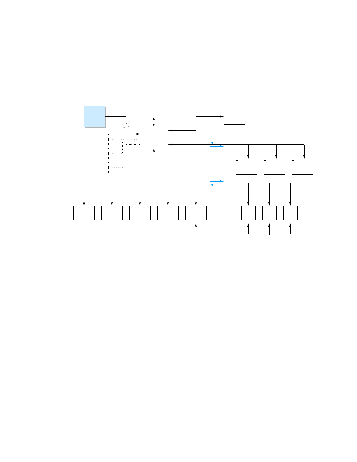
An Overview
NV9000-SE is designed to follow, as closely as possible, common tasks and facility structure to
create a more intuitive configuration process.
NV9000-SE fits into the routing control scheme as follows:
1. Getting Started
An Overview
9000-SE
SysMgr
PGSE
DB Config
UniConfig
Ethernet
SNMP
Ethernet
Ethernet
Command
GUI/
Status
(operators)
NV9000
System
Controller
Facility
Network
TallyUMD
Auto-
mation
Status
Control
Prim./Sec.
Status
Master
Control
Router
CP
Router Router
(DHCP)
CP CP • • •
(operators)
If using a previous version of NV9000-SE or older configuration software, contact Customer Support for information on using legacy applications.
The NV9000 system controller is comprised of a mixture of hardware and software components
that must be configured by the user before the system is placed into service.
• • •
Please note:
• Configuration
— The configuration process requires that certain conventions are followed. As
an important prerequisite, read this guide thoroughly before powering up the system for the first
time.
• Planning
— As with any configuration system, the more planning, the smoother the installation.
Prior to installation, spend time deciding on device naming conventions, where (and how) the
various system routers will be connected, and how panels will be laid out. These factors will
save time during the configuration “editing” process.
Understanding the NV9000-SE Concept
This section provides a high-level overview that simplifies the understanding of how NV9000-SE
fits into routing in general.
Configuration
Configuration (using NV9000-SE) is the process of creating a comprehensive database of your
inputs, outputs and devices. Initial configuration steps involve defining device interfaces, what
NV9000-SE Utilities • User’s Guide 5
Page 26

1. Getting Started
An Overview
ports on the NV9000 system controller the devices are connected to, and which protocols are used
to communicate with the NV9000 system controller. It is recommended that you have this “interface” information available before starting configuration.
At any time, you can easily add protocols to the NV9000 system controller if requirements change.
Unlike most control systems, NV9000-SE allows you to configure duplicate entries. For example,
you can configure three edit bays, each bay can have a VTR1, VTR2, VTR3, etc. instead of creating nine unique VTR names. Or, you can configure all physical routers as “level 1,” or have two
“SDI” routers. As you think about configuration details, this unique feature may provide a solution
to an operation problem.
Organizing Sources and Destinations
Depending upon your specific configuration, a device can be designated as a “source” or a “destination”—
To make selecting devices from a control panel easy and intuitive, devices are grouped in “categories.” A category can be used to group devices in any manner desired: by signal type, function, or
even by location within the facility. Categories may also be used as a way to create “exclusions.”
For more information, see Categories
or even both. For more information, see Devices on page 157.
on page 189.
The NV9000 system controller also supports “input fan out” mode where a single input (e.g., Tone)
may be used across many devices. For example, SD bars, HD bars and test can all share a common
tone (physical) input. However, unique to the NV9000 system controller, “output fan out” is also
supported. This means that a physical router output port may have more than one device name. This
is useful in situations where “multi-rate” equipment, such as a VTR that can play out SD or HD, is
used.
Control Panels
Control panels are the interface between operators and the routing hardware. How the control panel
is configured can have a major impact how well this interaction takes place. Minimizing the number of keystrokes needed to establish routes and using device mnemonics to help operators select
devices can help reduce possible operator errors. Control panels are programmable and use a configuration file to define attributes. These attributes include button names, operating modes and feature sets.
6 Rev 3.0 • 25 Mar 10
Page 27
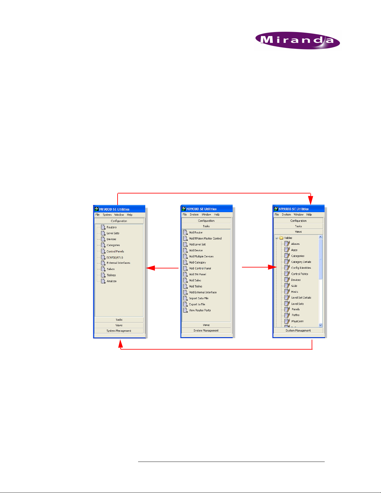
2. Using the Interface
The NV9000-SE interface is designed to help you quickly and easily perform configuration tasks.
The three panes used to manage configurations—Configuration, Tasks and Views—share database
tables. A change in one pane is reflected in the other panes. This means that you can make changes
using the interface that best suits your needs or comfort level. For example, when first creating configurations, wizards accessed through the ‘Tasks’ pane provide step-by-step guidance for entering
necessary data. Windows in the ‘Configuration’ pane enable you to manage existing information.
As you become an advanced user, tables accessed through the ‘Views’ pane enable you to adjust
configuration information in a specific database. In addition, the tables in the ‘Views’ pane provide
you with easy access to specific lists of information, such as currently connected routers, level set
assignments, currently added devices, and so on.
Changes in Configuration pages appear in related tables in the Views pane
Wizards
in the
Tasks pane
populate
pages in
the
Configuration
pane
Changes in tables in the Views pane appear in related Configuration pages
and related
tables in
the Views
pane
Configuration data can be updated through both pages and tables. The pages accessed through the
‘Configuration’ pane and the tables accessed through the ‘Views’ pane share databases. Changes
made in one interface appear in other interfaces that share that database. For example, if the name
of a level set is updated in the ‘Level Sets’ page, the name is automatically updated in the ‘Level
Sets’ table and the ‘Level Set Details’ table.
Although both a page and table may update the same information, each interface enables you to
perform specific tasks more efficiently. Pages enable you to update several pieces of information
for a single item through a single interface; tables are useful for updating a limited, specific amount
of information for several items at once. Not all pages and tables update the same information; different interfaces manage different, specific level set information.
NV9000-SE Utilities • User’s Guide 7
Page 28
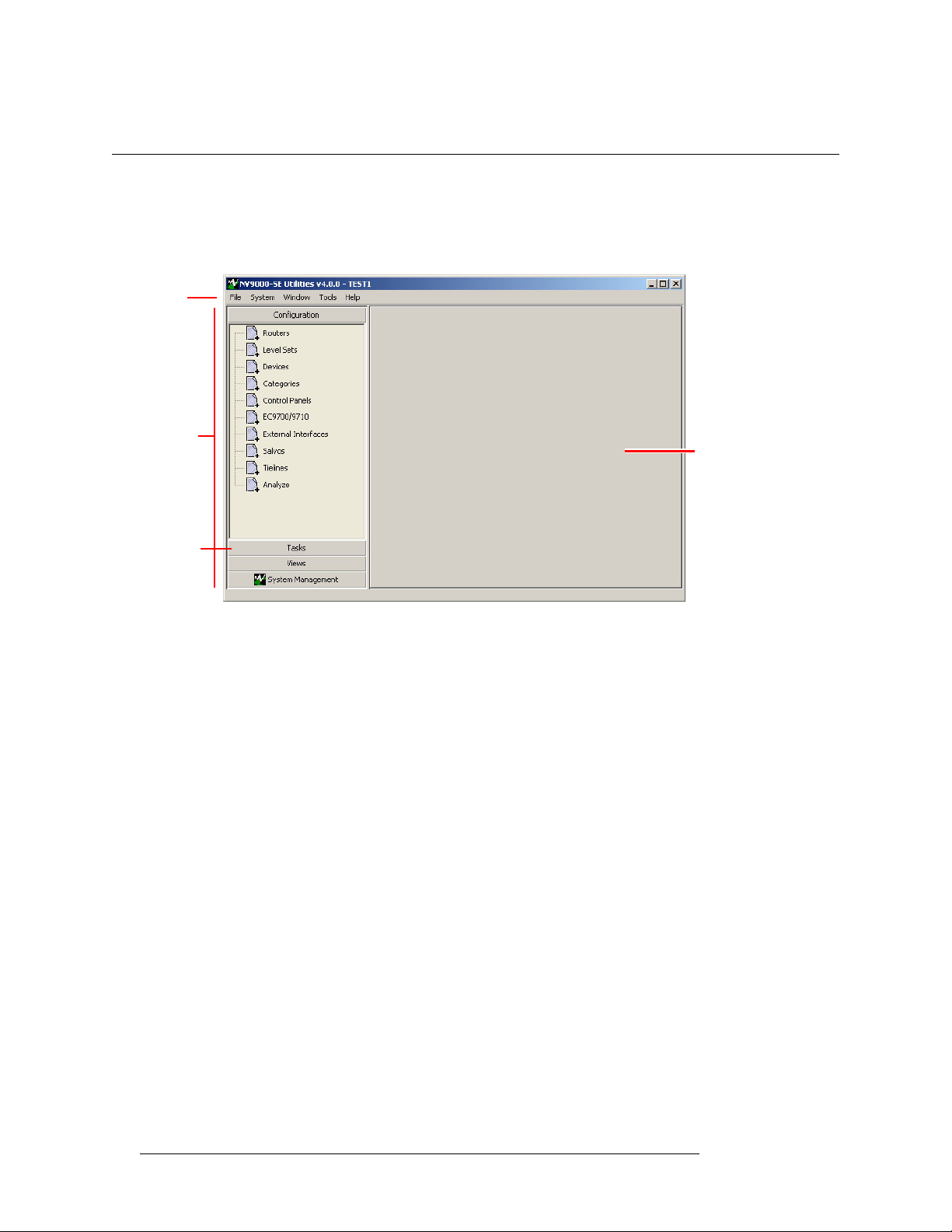
2. Using the Interface
The SE Utilities Window
The SE Utilities Window
The NV9000-SE interface is divided into two main areas: a navigation area and a work area, as
shown in Figure 2-1. When the application first launches, the work area is blank. A menu bar at the
top of the screen provides quick access to general tasks, such as opening, closing and saving files.
Menu Bar
Navigation
Area
Pane
Work Area
Figure 2-1. NV9000-SE Window
Navigation Area
The navigation area features four sections, called “panes.” Clicking on a pane slides it up to the top
of the navigation area to display a list of options. In Figure 2-1, the ‘Configuration’ pane has been
clicked, displaying a list of options related to configuration tasks. Clicking on an option title opens
related tabbed pages in the work area.
To scroll through panes in the navigation area, press CTRL+Tab on your keyboard.
Work Area
The work area displays tabbed windows (pages). In general, there are three types of windows that
display:
• Pages
•Table
• Wizard
— Lists all items of a selected type in the system or details for a selected item. Manages
almost all information for a selected, single item.
— Lists all items of a selected type in the system, based on specific, limited criteria, and
manages very specific information.
— A step-by-step guide that helps you perform a specific configuration task quickly and
accurately.
Pages, tables and wizards share databases so that changes in one interface updates all corresponding fields in all related interfaces.
To advance from field to field on a page, press TAB on your keyboard. To move between fields, but
in reverse, press SHIFT+TAB.
8 Rev 3.0 • 25 Mar 10
Page 29

2. Using the Interface
The SE Utilities Window
Common Commands
Throughout the work area certain common commands appear. These commands perform the same
action no matter where they appear. On multi-destination display areas, you can press ‘Esc’ on your
keyboard to cancel an action or press ‘Enter’ on your keyboard to accept a change.
Many tabbed windows have
These buttons become enabled or disabled (grey-out) on a moment-by-moment basis depending on
whether the current page and data entry require the button. Click a button to perform the related
function.
•
Previous — Opens the previous page in the data entry cycle.
•
Next — Continues to the next page in the sequence.
•
Finish — Saves the current information and completes the procedure; clears all fields so that new
information can be entered immediately.
•
Save — Saves the current information and completes the procedure.
•
Revert to Saved — Ignores any current changes and restores data to the last time it was saved.
•
Cancel — Clears the fields without saving any information.
•
X — Closes the window or dialog box. If clicked before Finish or Save is clicked, the window
closes without saving any changes.
Previous, Next, Finish and Cancel buttons at the bottom of the screen.
Tabs
Information is organized into tabbed windows. Clicking a tab brings the related window forward.
The tab that is currently forward is active. All other tabs in the background are inactive.
To close the currently active tab (and window), from the menu bar, select ‘Window > Close Active
Tab’. The active tab closes.
To close all inactive tabs, from the menu bar, select ‘Window > Close Inactive Tabs’. The inactive
tabbed windows close, but the active tab remains open.
Tables
Data entered in a page or wizard is saved in tables. Tables are accessed through the ‘Views’ pane.
Tables can be adjusted to make viewing information easier:
• Adjust the position and width of the table columns by sliding the column dividers between the
column headers.
• Sort the table based on the data in a specific column by clicking the column header. Clicking
once gives an ascending sort (Z to A); clicking again gives a descending sort (A to Z).
• Some dialog boxes or pages have check boxes. When a check box is checked, the corresponding item is selected; if a check box is unchecked, the item is deselected.
Entering Data
Data is entered in fields. Fields can be “free text” in which you type in the data, or fields have dropdown lists from which an entry is selected.
Menu Bar
The menu bar displays near the top of the window and is always present. The menu bar provides
access to menu options that perform system tasks. To open a menu, click on title on the menu bar. A
NV9000-SE Utilities • User’s Guide 9
Page 30
2. Using the Interface
Shortcuts
list of additional commands or a dialog box appears. Select the command or enter information in
the dialog box as directed. For more information on using each menu bar option, see the related
task in this User’s Guide.
There are 4 menus:
Shortcuts
File Provides commands for creating new configurations, opening existing configurations,
saving a configuration with a new name, importing and exporting configurations to zip
files, and exiting. (See Control Panels on page 231.)
System Opens the ‘Add Control System’ dialog box. See Managing System Parameters on
page 48.
Window Closes active or inactive windows in the work area.
Help Lists the software revision number and launches the online Help system.
Filters
Several pages have drop-down lists located at the top of the window, called “filters.” These filters
enable you to reduce the number of items listed to only those matching characters entered in the filter fields. For example, a Name filter returns only items whose name matches the characters
entered in the filter field.
NV9000-SE has several shortcut commands. Shortcuts allow you to perform a task without having
to select a menu from the menu bar and then a menu option. Some of these shortcut commands are
listed on the menus while others are performed anywhere in the interface by using keyboard
strokes.
All shortcuts are performed using keys on your keyboard. ‘Ctrl’ represents the Control key, ‘Shift’
the Shift key, ‘S’ the S key, and so on. A plus sign—’+’—between keys indicates that you press the
first key, and while keeping it depressed, press the second key. You can use the ‘Shift’ key to select
a contiguous items or use the ‘Ctrl’ key to select non-contiguous items in a list.
Double-click Option
To select and open any item in any page listed in the ‘Configuration’ pane, simply double-click on
it. A page opens displaying details for that item.
File Menu
Instead of selecting the ‘File’ menu from the menu bar and then a menu option, you can use the following keyboard strokes:
•‘Ctrl’
+ ‘N’ — Creates a new configuration.
•‘Ctrl’
+ ‘O’ — Opens a new configuration.
•‘Ctrl’
+ ‘S — Saves the current configuration.
10 Rev 3.0 • 25 Mar 10
Page 31

2. Using the Interface
Shortcuts
•‘Ctrl’ + ‘Shift’ + ‘S’ — A “save as” command that saves the current configuration and prompts
you to enter a new name.
Control Panel Keyboard
These shortcuts are used when a keyboard is attached to a virtual control panel:
• ‘D’ or ‘d’
— Selects a destination button type for the currently selected button. If the previous
button is also a destination button, the new destination button is assigned the next destination in
the list.
• ‘S’ or ‘s’
— Selects a source button type for the currently selected button. If the previous button
is also a source button, the new source button is assigned the next source in the list.
• ‘L’ or ‘l’
— Selects a level button type for the currently selected button. If the previous button is
also a level button, the new level button is assigned the next level in the list.
•‘C’ or ‘c’
— Selects a category button type for the currently selected button. If the previous but-
ton is also a category button, the new category button is assigned the next category in the list.
• ‘U’ or ‘u’
• ‘Delete’
•‘T’ or ‘t’
— Changes the currently selected button type to “Undefined.”
— The same as pressing ‘U’ or ‘u’.
— Changes the panel selection focus to the ‘Button Type’ drop-down list. Same as
clicking in the ‘Button Type’ field.
• ‘1’, ‘2’, ‘3’ or ‘4’
— Places focus in the first, second, third or fourth (as applicable) drop-down
list. Note that the drop-down list labeled ‘Button Type’, which is always the first drop-down
list, is skipped so pressing ‘1’. Pressing ‘1’ moves the selection focus to the next drop-down list
after the ‘Button Type’ drop-down list.
• ‘Alt’
+ ‘b’ — Returns selection focus to the button being configured.
• ‘Alt’
+ ‘Shift’ + ‘b’ — Same as ‘Alt’ + ‘b’.
•‘Tab’
— If a button is selected, focus is advanced to the next button. If a drop-down box is
selected, focus is advanced to the next drop-down box in rotation.
•‘Shift’
+ ‘Tab’ — If a button is selected, focus is reverted to the previous button. If a drop-down
box is selected, focus is reverted to the previous drop-down box in rotation.
Keyboard Shortcut Best Practices
When configuring source or destination buttons for control panels that incorporate a source or destination shift, it is recommended that devices be assigned so that the “Device 1” drop-down lists for
consecutive buttons in a row are assigned to contiguous devices in that drop-down box. Similarly
for the “Device 2” drop-down list, and so on.
For example, consider an NV9605 in limited XY mode, with the top row of buttons assigned as
sources and the bottom row assigned as destinations and there are 32 VTRs named VTR-1 through
VTR-32. Button 1 is configured for VTR-1 on Source Device 1 and VTR-17 on Source Device 2.
By doing this, the user can use the ‘Tab’ and ‘S’ keyboard shortcuts to quickly and effectively
assign the remaining 15 buttons on the top row. When completed, buttons 1 through 16 will have
VTR-1 through VTR-16 assigned to Source Device 1 and VTR-17 through VTR-32 assigned to
Source Device 2.
NV9000-SE Utilities • User’s Guide 11
Page 32

2. Using the Interface
Launching and Exiting the Application
Exiting Level Mode
To quickly exit level mode, select a category button.
Launching and Exiting the Application
To launch NV9000-SE, from your desktop double-click on the shortcut icon. The shortcut icon is
located where designated when installing the application. See Installation
Or
From the ‘Start’ menu, select ‘Programs > Miranda > NV9000-SE Utilities’.
To exit and close NV9000-SE, from the menu bar, select ‘File’ and then “Exit’.
on page 13.
12 Rev 3.0 • 25 Mar 10
Page 33

3. Installation
Installation of the NV9000-SE is automated and easy to perform. Depending on your operating system, exact procedures for starting the installation process may vary. In general, locate and open the
‘NV9000-SE Utilities.exe’ file on the CD provided to start installation. The ‘NV9000-SE Utilities
Installer’ window guides you through the installation process, step-by-step. At any time during the
installation process, click
NV9000-SE can be installed on the system controller if desired, as well as on a customer-supplied
computer.
Adding to a Network
NV9000-SE can be run on a computer that is part of a network. For networking purposes, Miranda
products use the IP address 192.168.x. Due to Miranda’s architecture, changes to this IP address are
generally not allowed. Changes to the IP address require changes to the registry and cannot be
changes through the NV9000-SE system.
Previous to return to the prior screen.
NV9000-SE Utilities • User’s Guide 13
Page 34

3. Installation
Installing the Application
Installing the Application
Follow these steps to install the NV9000-SE application. If you have any questions, contact
Miranda technical support.
How to Install the NV9000-SE Application
1 Place the CD provided in the CD-Rom drive of a computer hosting the application or on a net-
work.
2 Locate and open the ‘NV9000-SE Utilities.exe’ file. For detailed instructions, refer to your
operating system’s Help. The ‘NV9000-SE Utilities Installer’ window appears with the ‘Introduction’ screen displaying:
Figure 3-1. NV9000-SE Utilities Installer Window - Introduction Screen
3 Make sure all applications are closed while installation is proceeding. Read the introductory
information and click
Figure 3-2. NV9000-SE Utilities Installer Window - Choose Install Folder Screen
14 Rev 3.0 • 25 Mar 10
Next. The ‘Choose Install Folder’ screen appears:
Page 35

3. Installation
Installing the Application
4 Choose the folder where the application will be installed:
By default, the NV9000-SE is installed at:
select this folder, make no changes and click
Or
Click
Choose and browse to the folder location you want.
At any time, click
Restore Default Folder to restore the default folder location.
5 On the ‘Choose Shortcut Folder’ screen, select where the shortcut icon for launching the
NV9000-SE will appear:
C:\Program Files\Miranda\NV9000-SE Utilities\. To
Next.
Figure 3-3. NV9000-SE Utilities Installer Window, Choose Install Folder Screen
Click the corresponding radio button to select a shortcut folder location or to have no shortcut
folder. If placing the shortcut folder in a program group, select a group from the drop-down lists
provided. When selected, click
Next.
6 Verify that the information on the ‘Pre-Installation Summary’ screen is correct:
Figure 3-4. NV9000-SE Utilities Installer Window, Pre-Installation Summary Screen
NV9000-SE Utilities • User’s Guide 15
Page 36

3. Installation
Installing the Application
7 The ‘Installing NV9000-SE Utilities’ screen appears:
To update the information that displays, click Previous to return to the related screen, updating
information as needed. When done updating, click
Next on each screen until the ‘Pre-Installa-
tion Summary’ screen appears. When done verifying installation information, on the ‘PreInstallation Screen’, click
Next.
Figure 3-5. NV9000-SE Utilities Installer Window, Installing NV9000-SE Utilities Screen
Installation proceeds automatically.
Or
Click
Cancel to cancel installation.
8 When installation is complete, the ‘Installation Complete’ screen appears:
Figure 3-6. NV9000-SE Utilities Installer Window, Install Complete Screen
Click the radio button to restart your computer now or at a laster time, then click Done. It is recommended that you restart your computer at this time. The ‘NV9000-SE Utilities Installer’
window closes. The NV9000-SE is now installed.
16 Rev 3.0 • 25 Mar 10
Page 37

4. Configurations
Using NV9000-SE you create configurations for control panels and manage data for routers,
devices, salvos, tielines, and other switching related information. Configurations are written to system controllers, such as the NV9000, which in turn forward configuration information to connected
routers, control panels, and other devices. A system controller is the physical frame on which a
router control system application is loaded. For convenience, the combination—hardware and software—are referred to as the system controller. For details on managing system controllers, see Sys-
tem Management on page 33.
Configurations are saved as files, which in turn are saved in folders. A configuration folder is automatically created for each user that logs into NV9000-SE. Each configuration folder contains subfolders that store configuration data. Subfolders are titled to match the name of the configuration it
contains. A default subfolder titled ‘ControlSysDB’ is a prototype containing an “empty” default
configuration and opens the first time NV9000-SE is launched. Configurations can be manually or
dynamically updated.
Note About Networking
The system controller and NV9000-SE communicate using Ethernet connections and as part of a
network. Miranda products use the IP address 192.168.x.x. Due to Miranda’s product architecture,
changes to this IP address are generally not allowed. Changes to the IP address require changes to
the registry and cannot be changed through the NV9000-SE system. (See Changing System Con-
troller IP Address or Name on page 39.)
Implementing Configuration Changes
Using the ‘System Management’ pane, you can write configurations to system controllers in the
NV9000-SE system. Saving configuration changes on the NV9000-SE page or table in which the
changes were made only saves the changes to the database. To have configuration changes implemented and appear to control panel operators, the configuration must be written to a system controller. There are two ways to do this: 1) Write to the system controller and then reboot it separately
or 2) dynamically apply changes to the system controller, which in turn sends changes to the control panels and other devices without having to first write and then reboot the system controller.
Any physical changes to connections (e.g., cabling) require that the changes be written to the system controller and then the system controller rebooted. Physical changes include adding, removing
or changing any protocols used for router control or external interfaces and adding, removing or
changing routers and/or physical levels on routers.
Changes to configurations that do not include any physical connection changes may be written to
the system dynamically; no rebooting is required.
NV9000-SE Utilities • User’s Guide 17
Page 38

4. Configurations
Implementing Configuration Changes
How to Implement Configuration Changes
1 Click the ‘System Management’ pane to expand it and select the system controller you want to
manage. The ‘System Controller’ page appears:
Figure 4-1. Example of System Controller Page
2 In the ‘Control’ section:
aClick
bClick
Or
Click
ler dynamically. (This can only be used for configuration changes, not changes to physical connections on devices.)
18 Rev 3.0 • 25 Mar 10
Write Configuration to write saved configuration changes to the control panel.
Reboot to stop the control system software and system controller and then restart the
system controller.
Dynamic Update to write and update the database and send changes to the system control-
Page 39

Working With Configuration Files
Configuration files are a powerful tool when setting up facility control panels.
The control panel configuration file can be:
• Unique to each control panel.
• Shared if you want multiple control panels to have identical settings.
• Shared if you want multiple control panels to have common settings, which can then later be
individualized.
The configuration file used by a particular panel is defined by its assigned ID number. If desired,
the ID number can be changed “on the fly,” enabling a control panel’s configuration settings to
vary.
A control panel configuration file is created when a control panel is added to the NV9000-SE system. By default, NV9000-SE creates a default pathname for the configuration file by concatenating
\nvision\envy\bin\usersys\live\ and the configuration file name. The pathname is expressed
relative to the hard disk of any NV9000 server.
Normally, the file name extensions reflect the control panel type. For instance, an NV9601 configuration file has a
control panels of the same type.
601 extension. Control panel configuration files can be used by one or multiple
4. Configurations
Working With Configuration Files
Different control panel pages and tables manage specific information. The information that displays differs from control panel to control panel.
Opening a Configuration
Configurations can be opened at any time. Configurations can be imported from a directory location or from a zip (compressed) file, such an archived file.
How to Open a Configuration from a Directory Location
1 Launch NV9000-SE. (See Launching and Exiting the Application on page 12.)
2 From the menu bar, select ‘File’ and then ‘Open’. The ‘Select a Config to Open’ dialog appears:
Figure 4-2. Select a Config to Open Dialog Box
3 Click on a name to open the corresponding configuration and click OK.
Or
Click
Cancel to close the dialog box without opening a configuration.
The configuration data populates pages and tables in NV9000-SE Utilities.
NV9000-SE Utilities • User’s Guide 19
Page 40

4. Configurations
Working With Configuration Files
Creating or Changing a Configuration File
A control panel configuration file is created whenever a control panel is configured using NV9000SE Utilities. (See Adding a Control Panel
pathname for the configuration file by concatenating “
the configuration file name. The pathname is expressed relative to the hard disk of the system controller.
New “blank” configuration files can be created as needed. Essentially a new configuration file is
“empty,” having structure but no content.When a configuration is created, a new subfolder is added
for the user currently logged in and the configuration file stored at that location. The new subfolder
is titled the same name entered for the ‘Configuration Name’ when the new configuration is created.
Normally, the file name extensions reflect the control panel type. For instance, an NV9601 configuration file has a
the same type.
The configuration file assigned to a control panel can be updated at any time using the ‘Panels’
table. Pathnames for specific configuration files can be added, updated or deleted using the ‘Paths’
table. Both tables are accessed through the ‘View’ pane. For instructions on managing pathnames,
see Creating, Updating and Deleting Configuration File Pathnames
on page 240.) By default, NV9000-SE creates a default
\nvision\envy\bin\usersys\live\” and
601 extension. Panel configuration files can be used by one or multiple panels of
on page 24.
How to Create a New “Empty” Configuration File
1 Launch NV9000-SE. (See Launching and Exiting the Application on page 12.)
2 From the menu bar, select ‘File’ and then ‘New’. The ‘Input’ dialog appears:
Figure 4-3. Input Dialog Box for New Configuration
3 Enter a name for the configuration in the field provided and click OK.
Or
Click
Cancel to close the dialog box without creating a new configuration.
A “blank” configuration opens. Fields in pages and tables within NV9000-SE Utilities are
blank, reflecting that no configuration data has been selected or saved.
How to Associate a Different Configuration File with a Control Panel
1 Launch NV9000-SE. (See Launching and Exiting the Application on page 12.)
2 From the Navigation area, select the ‘Views’ pane and then ‘Panels’. The ‘Panels’ table
appears, as shown in Figure 4-4.
To narrow the list of panels that display, enter the first characters of a control panel name in the
‘Name Filter’ field. The list is automatically reduced to display only panels matching that character string.
Or
20 Rev 3.0 • 25 Mar 10
Page 41

4. Configurations
Working With Configuration Files
Enter the first characters of a user name in the ‘User Filter’ field. The list only displays panels
with that assigned user.
Figure 4-4. Panels Table
3 Locate the row listing the control panel being updated.
4 Click on the ‘Configuration File’ field to activate it, and from the drop-down list, select a new
configuration file.
5Click
6Click
Save.
Or
To revert to the previously saved configuration, click
X on the window title tab to close the table.
Revert to Saved.
Saving Configuration Changes
A configuration is created whenever a control panel is added using the NV9000-SE. Similarly, configurations are updated whenever an existing control panel is modified. To save an updated configuration, click
NV9000-SE Utilities • User’s Guide 21
Save located at the bottom of any control panel configuration page. (See Adding a
Page 42

4. Configurations
Working With Configuration Files
Control Panel on page 240 or Updating Control Panel Details on page 349.) The Revert to Saved
button discards current changes and reverts to the previously saved changes.
Important Saving a configuration changes does not write the configuration to the system
controller for distribution to control panels. For more information, see Imple-
menting Configuration Changes on page 17.
Configurations are always “saved” whenever
close a page without “saving” changes, or click
This feature enables you to easily clear mistakes.
Save is clicked. If you open a different configuration,
Revert to Saved, the current changes are discarded.
Deleting or Renaming Configuration Folders
To delete or rename a configuration folder, you must locate the folder in your local operating system and use file system commands to delete or rename the folder. Be careful! Certain file system
commands may make the folder inaccessible to NV9000-SE. Refer to your local operating system
for instructions on managing files and folders.
Adding Computers to Existing EC9700 or EC9710 Configurations
EC9700 and EC9710 are virtual control panels that run on a computer. (See EC9700 and EC9710
Panels on page 385.) Using the ‘GUIs’ table accessed through the ‘Views’ pane, a new computer
can be associated with an existing EC9700 or EC9710 control panel. The computer, or Windows
user, is associated by adding a new control panel and selecting the configuration file for the
EC9700/EC9710 control panel you want. Using this table, associations can also be removed.
Selecting an existing configuration is similar to performing a “Save As” function. An identical
copy of the configuration is saved on the newly assigned computer.
How to Add an EC9700/EC9710 Control Panel to an Existing Configuration
1 Launch NV9000-SE. (See Launching and Exiting the Application on page 12.)
2 From the Navigation area, select the ‘Views’ pane and then ‘GUIs’. The ‘GUIs’ table appears,
as shown in Figure 4-5.
22 Rev 3.0 • 25 Mar 10
Page 43

4. Configurations
Working With Configuration Files
To narrow the list of EC9700/EC9710 panels that display, enter the first characters of a control
panel name in the ‘Computer (or Windows User) Name Filter’ field. The list is automatically
reduced to display only control panels matching that character string.
Figure 4-5. GUIs Table
3Click Add. A blank row appears at the bottom of the list of EC9700/EC9710 panels.
4 In the blank row, click on a cell in a column to activate it and enter information, as follows:
Section Description
Computer (or
Windows User)
Name
User Name From the drop-down list, select a user name. User names are managed through
Configuration From the drop-down list, select a configuration file. A control panel
Language From the drop-down list, select a language. Currently, only English is supported.
Description Enter an optional description of the control panel.
5Click
Save to save your changes.
Enter the name of the computer of the user’s name on the network where the
control panel application resides.
the ‘User’ table. (See Managing User Names
configuration file is created when a control panel is added to the NV9000-SE
system. By default, NV9000-SE creates a default pathname for the configuration
file by concatenating “
configuration file name. The pathname is expressed relative to the hard disk of
any NV9000 server.
\nvision\envy\bin\usersys\live\” and the
on page 509.)
6 (Optional) Add further details using the ‘EC9700/9710’ page accessed through the ‘Configura-
tion’ pane. To add details to the control panel, locate the control panel and perform steps 5
through 14 as described in Adding an EC9700/EC9710 Panel
on page 385. (See Locating and
Viewing Existing EC9700/EC9710 Panels on page 399.)
NV9000-SE Utilities • User’s Guide 23
Page 44

4. Configurations
Working With Configuration Files
7Click X on the window title tab to close the table.
Creating, Updating and Deleting Configuration File Pathnames
A control panel configuration file is created when a control panel is added to the NV9000-SE system. By default, NV9000-SE creates a default pathname for the configuration file by concatenating
\nvision\envy\bin\usersys\live\ and the configuration file name. The pathname is expressed
relative to the hard disk of the system controller. Normally, the file name extensions reflect the control panel type. For instance, an EC700 configuration file has a
figuration files can be used by one or multiple panels of the same type. Changing the configuration
file changes the configuration for the selected control panel, which may impact what the operator
sees and the functions allowed.
To update the configuration file associated with any control panel, you change the pathname that
points the control panel to the configuration file.
Every control panel configuration and salvo file defined in a configuration are listed on the ‘Paths’
table accessed through the ‘Views’ path. Do not use this table for data entry. Although this table
allows pathnames to be added, updated or deleted, entries in this table are normally defined elsewhere.
700 extension. Control panel con-
In addition, the ‘GUIs’ table, accessed through the ‘Views’ pane, may be used to associate a new
configuration file with an EC9700 or EC9710 panel.
How to Update the Configuration File Pathname for an EC9700 or EC9710
The following are instructions for changing the configuration file associations with an EC9700 or
EC9710 control panel. For all other panels, see How to Update a Configuration File Pathname
page 26.
1 Launch NV9000-SE. (See Launching and Exiting the Application
2 From the Navigation area, select the ‘Views’ pane and then ‘GUIs’. The GUIs’ table appears, as
shown in Figure 4-4.
on page 12.)
on
24 Rev 3.0 • 25 Mar 10
Page 45

4. Configurations
Working With Configuration Files
To narrow the list of panels that display, enter the first characters of a control panel name in the
‘Computer (or Window User) Name Filter’ field. The list is automatically reduced to display
only control panels matching that character string.
Figure 4-6. GUIs Table
3 Locate the row listing the control panel being updated.
4 Click on the ‘Configuration File’ field to activate it, and from the drop-down list, select a new
configuration file.
5Click
Save.
Or
To revert to previously saved configuration, click
6Click
X on the window title tab to close the table.
Revert to Saved.
NV9000-SE Utilities • User’s Guide 25
Page 46

4. Configurations
Working With Configuration Files
How to Create a New Configuration File Pathname
1 Launch NV9000-SE. (See Launching and Exiting the Application on page 12.)
2 From the Navigation area, select the ‘Views’ pane and then ‘Paths’. The ‘Paths’ table appears:
Figure 4-7. Paths Tables
3Click Add. A blank row is added to the list of pathnames.
4 In the blank row, in the ‘File Path’ column, click in the field to activate it and enter the full loca-
tion path for the new configuration pathname.
5 In the same row, in the ‘File Type’ column, click in the field to activate it and from the drop-
down list choose a configuration file type.
6Click
Save. An ‘ID’ number automatically appears for the newly added pathname.
Or
To revert to the previously saved configuration, click
7Click
X on the window title tab to close the table.
Revert to Saved.
How to Update a Configuration File Pathname
1 Launch NV9000-SE. (See Launching and Exiting the Application on page 12.)
2 From the Navigation area, select the ‘Views’ pane and then ‘Paths’. The ‘Paths’ table appears,
as shown in Figure 4-8.
26 Rev 3.0 • 25 Mar 10
Page 47

4. Configurations
Working With Configuration Files
To narrow the list of panels that display, enter the first characters of a pathname the ‘File Filter’
field. The list is automatically reduced to display only pathnames matching that character
string.
Figure 4-8. Paths Tables
3 Locate the row listing the pathname being updated.
4 In the ‘File Path’ column, click in the field to activate it and enter a new location for the path-
name. Be sure to enter the full pathname.
5 In the ‘File Type’ column, click in the field to activate it and from the drop-down list choose a
new configuration file type.
6Click
Save.
Or
To revert to the previously saved configuration, click
7Click
X on the window title tab to close the table.
Revert to Saved.
How to Delete a Configuration File Pathname
1 Launch NV9000-SE. (See Launching and Exiting the Application on page 12.)
2 From the Navigation area, select the ‘Views’ pane and then ‘Paths’. The ‘Paths’ table appears,
as shown in Figure 4-9.
NV9000-SE Utilities • User’s Guide 27
Page 48

4. Configurations
Importing and Exporting Configurations
To narrow the list of pathnames that display, enter the first characters of a pathnames name in
the ‘File Filter’ field. The list is automatically reduced to display only pathnames matching that
character string.
Figure 4-9. Paths Tables
3 Click anywhere in the row listing the pathname being deleted.
4Click
5Click
6Click
Delete. The row is removed from the table.
Save.
Or
To revert to the previously saved configuration, click
X on the window title tab to close the table.
Importing and Exporting Configurations
Configurations can be imported and exported. The configuration may be one created using
NV9000-SE or a non-NV9000-SE configuration.
Configurations can be exported as compressed files, such as Zip files. This is convenient when
archiving configurations or moving configurations between computers. At any time, compressed
files can be imported and decompressed for viewing or updating. When a compressed file is
imported it is not opened, instead a new configuration is created from the contents of the compressed file. This ensures that the archived copy remains intact and all changes are made to a new,
separate configuration file.
Revert to Saved.
Warning Do not import or export compressed files created outside NV9000-SE.
28 Rev 3.0 • 25 Mar 10
Page 49

4. Configurations
Importing and Exporting Configurations
By default, archived compressed files are located in C:\Documents and Settings\ [current
user]\My Documents.
How to Import from a Compressed Configuration File
1 Launch NV9000-SE. (See Launching and Exiting the Application on page 12.)
2 From the menu bar, select ‘File’ and then ‘Import from Zip Archive’. The ‘Open’ dialog box
appears:
Figure 4-10. Open Dialog Box
3 Select the compressed file to be opened and click Open. The ‘Input’ dialog box appears, as
shown in Figure 4-3.
4 Enter a name for the new configuration in the field provided and click
contents are decompressed and copied to a new configuration folder. Go to Step 4.
Or
Click
Cancel to close the dialog box without creating a new configuration.
The configuration data appears in fields on pages when a pane is selected.
OK. The compressed file
NV9000-SE Utilities • User’s Guide 29
Page 50

4. Configurations
Analyzing Configurations
How to Export to a Compressed File
1 Launch NV9000-SE. (See Launching and Exiting the Application on page 12.)
2 From the menu bar, select ‘File > Export to Zip Archive’. The ‘Save’ dialog appears:
Figure 4-11. Save Dialog Box
3 Enter a ‘File Name’ for the exported file in the field provided and click Save. The file is com-
pressed and saved.
Or
Click
Cancel to close the dialog box without exporting the configuration.
How to Import a Non-NV9000-SE Configuration
1 Launch NV9000-SE. (See Launching and Exiting the Application on page 12.)
2 Save the configuration being imported as a zip archive file and save it to:
NVISION\ENVY\USERSYS\SAVED\xxx.ZIP
3 Copy the zip file onto the computer or system controller running NV9000-SE. (If needed, copy
the zip file to a removable medium, such as an USB stick.)
4 From the menu bar, select ‘File’ and then ‘Import from Old Configuration Archive’.
5 On the ‘Open’ dialog box that appears, browse and locate the Zip file, and then click
The file is imported and the configuration read into NV9000-SE. Be sure to save this file to preserve the formatting.
6 Update NV9000 system controller software to use NV9000-SE and the newly uploaded config-
uration file. For more information and support, contact Miranda technical support.
Analyzing Configurations
Open.
Using the ‘Analyze’ page, different diagnostic analyses of the current configurations can be performed. When an analysis is performed, the results display in a separate tabbed window titled
‘Analyze Results’. Analyses are based on functionality. Each functionality lists what is diagnosed
when a report is run. You can choose to run all reports, or just selected ones.
30 Rev 3.0 • 25 Mar 10
Page 51

4. Configurations
Analyzing Configurations
How to Analyze a Configuration
1 Launch NV9000-SE. (See Launching and Exiting the Application on page 12.)
2 From the Navigation area, select the ‘Configuration’ pane and then ‘Analyze’. The ‘Analyze’
page displays, as shown in Figure 4-12. To view the entire page, scroll up and down using the
scroll bar on the right-hand side.
Figure 4-12. Analyze Page (Partial View)
3 Check the check box next to the report you want to run, and then click Run.
To check all check boxes, click
Or
Click
Clear All to remove all check marks in all check boxes. Analyses are only performed on
those categories with checked check boxes.
For details of what is analyzed for each option, refer to the ‘Analyze’ page. Each check box is
followed by a list of what is analyzed for that grouping.
NV9000-SE Utilities • User’s Guide 31
Set All.
Page 52

4. Configurations
Analyzing Configurations
4 The results of the analysis displays on the ‘Analyze Report’ page in a ‘tree’, as shown in
Figure 4-13. Click the ‘Analyze Report’ page window tab to bring the page forward.
Figure 4-13. Analyze Report Page
5 To view details, click on the + to expand a level in the ‘tree’.
Or
Click
Expand All to expand all levels.
Or
Click
Collapse All to contract all levels.
6 To print a report, exactly as it displays, click
Print. A report is sent to the printer connected to
the computer running NV9000-SE Utilities. The levels appear in the print out, either expanded
or collapsed, exactly as they appear on the ‘Analyze Report’ page.
7Click
X on the window title tab to close the page.
32 Rev 3.0 • 25 Mar 10
Page 53

5. System Management
System controllers, such as the NV9000, write configuration changes to control panels and other
routing devices. Configurations cannot be applied to devices until a system controller has been
added to NV9000-SE. To view all currently added system controllers, from the ‘Navigation’ pane
select ‘System Management’. System controllers display in the left-hand pane. Click on a system
controller name to view details, which display in the right-hand page.
A system controller is the physical frame on which the router control system software is loaded.
For convenience, the combination—hardware and software—are referred to as the system controller.
System controllers currently communicating with NV9000-SE display with a green icon. When
communication is disrupted, the icon is red. A yellow icon indicates that communication exists, but
it is of poor quality. All tasks performed in NV9000-SE should be done when communication with
the system controller is good, indicated by a green icon.
About System Controllers
System controllers communicate changes made in NV9000-SE Utilities to all control panels, routers and other connected devices. Each system controller has a separate server application. Depending on the NV9000 server, up to 16 routers, 4,096 destinations, 256 EC9700/EC9710 panels, and
128 control panels can be supported. Optional panel network cards to extend the number of control
panels to 1,024 are available.
Router control systems are software applications that reside on the system controller and communicate with NV9000-SE Utilities through Ethernet (NIC) ports. Each port has a unique IP address.
IP Addresses
An IP address is a 32-bit number given by four 8-bit values (octets) separated by periods:
192.168.97.87 (for example). The number is comprised of a subnet and a frame address.
Each network must be a distinct subnet. In NV9000-SE Utilities, the subnet mask is typically
255.255.255.0. Using that subnet mask, a device’s address is the last octet in the address. For example, if the router’s full IP address is 192.168.97.87, the router’s frame address is 87 and the subnet
is 192.168.97. A frame address can range from 1 to 254. The values 0 and 255 are not allowed
because they have special functional meaning.
Together the subnet and the frame address form an IP address which identifies a device or system
controller on its subnet. For frames to be distinguishable on the network, all IP addresses must be
distinct.
Your subnet masks need not be 255.255.255.0. If yours differ, the frame address range will be
something other than 1–254.
System controllers are assigned a specific IP address. Do not change the IP address without first
contacting Technical Support. System controllers are assigned the following IP addresses:
NV9000-SE Utilities • User’s Guide 33
Page 54

5. System Management
About System Controllers
• NV9000 system controllers – 192.168.97.1 for the primary controller and 192.168.97.2 for a
secondary (redundant) controller.
• NV915 system controllers – 192.168.2.1 for the primary controller and 192.168.2.2 for the secondary controller.
The computer running NV9000-SE Utilities must be on the same subnet (255.255.255.0) and
have the same subnet mask (e.g., 192.168.97 for NV9000 system controllers). However, the last
number, the frame address, must be anything else but the number assigned to the system controller
(1 or 2). For example, the computer running NV9000-SE Utilities may have the IP address
192.168.97.24, but not 192.168.97.1 (or 192.168.97.2 if running a secondary, redundant system
controller).
IP addresses for the ports communicating with routers start at 192.168.1.5 (could vary slightly) to
192.168.1.40.
IP addresses for the ports communicating with control panels are divided into two pools of
addresses (DHCP is used to determine the address):
• Primary server pool — 192.168.1.41 through 192.168.1.150
• Redundant or secondary server pool — 192.168.1.151 through 192.168.1.254
Important Do not use any other IP addresses. Other addresses are reserved for other
purposes.
Logs
The system controller maintains extensive logs of all system processes. These logs are used for
troubleshooting throughout the system. You can set a variety of logging “levels” as desired. Logs
are located in the
Descriptions of each logging level are listed below:
No logging No error logging is performed.
Log errors Only critical system errors are logged (e.g., loss of a server).
Log warnings Only warnings and errors are logged, (e.g., loss of a backup control card).
Log system events This level of logging includes the two previous levels, plus system events (e.g., a
Log transactions This level includes the three previous levels, plus a record of all messages between
Log all events All system activity is written to the logs.
Log debugging info Extensive information about errors. (Use this option only under Miranda direction.)
Log verbose
debugging info
NVISION\envy\userlocal folder on the server’s C:\ or D:\ drive.
panel or a router dropping off line).
all system components (e.g., each time a panel sends a request).
Use caution: it quickly fills the hard drive with data.(Use this option only under
Miranda direction.)
34 Rev 3.0 • 25 Mar 10
Page 55

Managing System Controllers
The ‘System Management’ page displays information about a system controller in addition to providing access to system controller controls.
5. System Management
Managing System Controllers
Figure 5-1. Example of System Management Page
The ‘System Management’ page displays the following information:
Section Description Related Topic
Controller Summary Lists the IP address currently assigned to each system
controller added to NV9000-SE, including the “health”
of the connection and whether the system controller is
currently active. Each system controller is assigned an
identification number, listed in the ‘Controller Number’
field.
Any faults or issues are listed in the ‘Controller Faults’
area below the summary fields.
Router Summary Lists all routers currently added to NV9000-SE. The
‘Active On’ column lists which system controller is
assigned to each router.
Panel Summary Lists all control panels currently added and which system
controller it is connected to. A “0” denotes no
connection.
NV9000-SE Utilities • User’s Guide 35
Changing System
Controller IP
Address or Name on
page 39
Routers
on page 61
Control Panels
page 231
on
Page 56

5. System Management
Managing System Controllers
Section Description Related Topic
External Interface
Summary
License Summary Lists any protocols being used and onto which system
At the bottom of the page are several buttons grouped by function. Each button performs a specific
configuration, management or maintenance task. The button lists either the current computer system running NV9000-SE or ‘Controller 1’ or ‘Controller 2’. Controller 1 refers to the primary system controller. If a second, redundant system controller is running, that is referred to as
Controller 2.
When a button option is not available, the button is dimmed (greyed-out). System management buttons are as follows:
•
Dynamic Update — Can be used to 1) write to and update the database and, 2) send changes to
the system controller dynamically. (This can only be used for configuration changes, not
changes to physical connections on devices. For updating the database after making physical
connection changes click
•
Read Configuration — Reads the configuration currently on the system controller and enters it
into the NV9000-SE database.
•
Write Configuration — Writes saved configuration changes to the system controller.
•
Restart — Stops the system controller and then starts it again.
•
Start — Starts the system controller if it has been stopped.
•
Stop — Stops the control system software on the system controller, but leaves the system con-
troller running.
•
Reboot — Stops the control system software and system controller and then restarts the system
controller.
•
Shutdown — Stops the control system software and system controller.
Lists all external applications currently added to the
system.
controller the protocol is loaded.
Write Configuration).
External Interfaces
on page 409
Protocols
515
on page
Adding System Controllers
System controllers can be added at any time using the ‘Add Control System’ dialog box accessed
from the ‘System’ menu on the menu bar. (See Menu Bar
NV9000-SE must be on the same subnet and have the same IP settings as the system controller in
order to have the system controller added. (See About System Controllers
36 Rev 3.0 • 25 Mar 10
on page 9.) The computer running
on page 33.)
Page 57

5. System Management
Managing System Controllers
How to Add a System Controller
1 Launch NV9000-SE. (See Launching and Exiting the Application on page 12.)
2 From the menu bar, select ‘System’. The ‘Add Control System’ dialog box appears:
Figure 5-2. Add Control System Dialog Box
3 Enter a ‘Control System Name’ in the field provided. The name must have fewer than 256 char-
acters. While there is no restriction on the characters used, it is recommended that you use
alphanumeric characters only and no symbols or punctuation marks.
4 Enter a ‘Controller1 IP address’ for the system controller’s primary server in the field provided.
If the address has been used already, NV9000-SE displays an alert.
The IP address for NV9000 system controllers is 192.168.97.1 for the primary controller and
192.168.97.2 for a secondary (redundant) controller. NV915 system controllers the IP address
is 192.168.2.1 for the primary controller and 192.168.2.2 for the secondary controller. If running NV9000-SE remotely, connections are usually made using the “house” net.
5 If the system controller has a redundant server, check the ‘Redundant’ check box and enter the
redundant server’s IP address in the ‘Controller2 IP address’ field that appears.
6Click
7 Repeat steps 2 though 5 until all system controllers are added.
8Click
9Click
Add. The system controller is added and all fields cleared.
Save to save all added system controllers and close the dialog box.
Or
Click
Cancel to close the dialog box without saving changes.
X on the window title tab to close the dialog box.
Starting, Stopping or Shutting Down
System controllers can be started, stopped or completely shut down at any time.
• Shutting down a system controller immediately stops all communication between the system
controller and associated devices.
• Stopping a system controller stops all communication between the system controller and associated devices in addition to temporarily stopping the control system software, but leaves the system controller running.
NV9000-SE Utilities • User’s Guide 37
Page 58

5. System Management
Managing System Controllers
How to Start, Stop or Shut Down a System Controller
1 Launch NV9000-SE. (See Launching and Exiting the Application on page 12.)
2 From the Navigation area, select the ‘System Management’ pane and then select the system
controller you want to manage.
3 In the ‘Control’ section at the bottom of the page, click
action:
•
Start — Starts the system controller if it has been stopped.
•
Stop — Stops the control system software on the system controller, but leaves the system
controller running.
•
Shutdown — Stops the control system software and system controller.
Rebooting a System Controller
Depending on the configuration change, you may need to reboot the system controller in order to
have the configuration communicated to attached devices. If making changes to physical connections (e.g., cabling), you must first write changes to the system controller and then reboot the system controller in order to save your changes. If making virtual changes (e.g., no changes to
cabling), you do not need to write changes and then reboot. Instead, you can select
to save your changes dynamically without rebooting. See Implementing Configuration
Update
Changes on page 17.
Start, Stop or Shutdown to perform that
Dynamic
How to Reboot a System Controller
1 Launch NV9000-SE. (See Launching and Exiting the Application on page 12.)
2 From the Navigation area, select the ‘System Management’ pane and then select the system
controller you want to manage.
3 In the ‘Control’ section at the bottom of the page, click
rent activity, shuts down and then restarts.
Reboot. The system controller stops cur-
Selecting a System Controller to “Ignore”
Ignoring a system controller tells NV9000-SE to not include the system controller in status reports,
and logs. This can be helpful when running multiple system controllers.
How to Ignore a System Controller
1 Launch NV9000-SE. (See Launching and Exiting the Application on page 12.)
2 From the Navigation area, select the ‘System Management’ pane and then select the system
controller you want to manage.
3 Right-click on the system controller and from the pop-up menu that displays and select ‘Ignore
Control System’.
Removing a System Controller
Removing a system controller removes it from the ‘System Management’ pane in NV9000-SE and
stops all communication between the system controller and all devices. Be careful! When removing
a system controller there is no confirmation dialog box; this action cannot be undone. If a system
38 Rev 3.0 • 25 Mar 10
Page 59

controller is removed by accident, it must be added again to restore communication. See Adding
System Controllers on page 36.
How to Remove a System Controller
1 Launch NV9000-SE. (See Launching and Exiting the Application on page 12.)
2 From the Navigation area, select the ‘System Management’ pane and then select the system
controller you want to manage.
3 Right-click on the system controller and from the pop-up menu that displays and select
‘Remove Control System’. The system controller is removed and all communication with the
controller immediately ceases.
Managing System Controller Communication
System controllers communicate through a network. System controller names and IP addresses can
be updated at any time. However, it is important to remember that any changes may have an immediate impact on communication. Changing the name of a system controller immediately updates the
name in all tables and display fields in the NV9000-SE in which the name appears.
5. System Management
Managing System Controller Communication
System controllers are assigned a specific IP address. For NV9000 system controllers the IP
address is 192.168.97.1 for the primary controller and 192.168.97.2 for a secondary (redundant)
controller. For NV915 system controllers IP address is 192.168.2.1 for the primary controller and
192.168.2.2 for the secondary controller. If running NV9000-SE remotely, connections are usually
made using the “house” net.
Changing System Controller IP Address or Name
The IP address or name assigned to a system controller can be changed at any time. However,
changes to IP addresses immediately impact communication between the system controller and
NV9000-SE. Make sure that the computer running NV9000-SE and the system controller are on the
same subnet mask and do not have the same frame address. (See About System Controllers
33.)
Changing the name of a system controller immediately updates the name in all tables and display
fields in NV9000-SE in which the name appears.
How to Change IP Address or Name
1 Launch NV9000-SE. (See Launching and Exiting the Application on page 12.)
2 From the Navigation area, select the ‘System Management’ pane.
3 Select a system controller and right-click to display a pop-up menu.
on page
NV9000-SE Utilities • User’s Guide 39
Page 60

5. System Management
Managing System Controller Communication
4 Select ‘Edit Control System’. The ‘Edit Control System’ dialog box appears:
Figure 5-3. Edit Control System Dialog Box
5 Update the ‘Control System Name’ in the field provided. The name must have fewer than 256
characters. While there is no restriction on the characters used, it is recommended that you use
alphanumeric characters only and no symbols or punctuation marks.
6 Update the ‘Controller1 IP address’ of the system controller’s primary server in the field pro-
vided. If the address has been used already, NV9000-SE displays an alert.
The IP address for NV9000 system controller is 192.168.97.1 for the primary controller and
192.168.97.2 for a secondary (redundant) controller. NV915 system controllers the IP address
is 192.168.2.1 for the primary controller and 192.168.2.2 for the secondary controller. If running NV9000-SE remotely, connections are usually made using the “house” net.
7 If the system controller has a redundant server, update the redundant server’s IP address in the
‘Controller2 IP address’ field that appears.
8Click
9Click
Save to save your changes and close the dialog box.
Or
Click
Cancel to close the dialog box without saving changes.
X on the window title tab to close the dialog box.
Changing or Viewing DHCP
The Dynamic Host Configuration Protocol (DHCP) is a computer networking protocol used by
hosts (DHCP clients) to retrieve IP address assignments and other configuration information. If
using a DHCP host, you can update the DHCP at any time.
How to Change or View the DHCP
1 Launch NV9000-SE. (See Launching and Exiting the Application on page 12.)
2 From the Navigation area, select the ‘System Management’ pane.
3 Select a system controller and right-click to display a pop-up menu.
4 Select ‘Edit/View DHCP’. Current DHCP information displays.
5 Update the DHCP as needed and click
Or
Click
Cancel to close the dialog box without saving changes.
40 Rev 3.0 • 25 Mar 10
Save to save your changes and close the dialog box.
Page 61

5. System Management
Managing System Controller Communication
6Click X on the window title tab to close the dialog box.
Changing or Viewing SNMP
Simple Network Management Protocol (SNMP) is a UDP-based network protocol. It is often used
in network management systems to monitor network-attached devices for statuses that may require
administrative attention.
How to Change or View the SNMP
1 Launch NV9000-SE. (See Launching and Exiting the Application on page 12.)
2 From the Navigation area, select the ‘System Management’ pane.
3 Select a system controller and right-click to display a pop-up menu.
4 Select ‘Edit/View SNMP’. Current SNMP information displays.
5 Update the SNMP as needed and click
Or
Click
Cancel to close the dialog box without saving changes.
6Click
X on the window title tab to close the dialog box.
Save to save your changes and close the dialog box.
Changing or Setting a Virtual IP
A virtual IP is a single IP address that two system controllers can share. This is helpful in systems
using a primary system controller and a secondary system controller, for redundancy. The active
system controller is always assigned the virtual IP. This means that should one of the system controllers becomes inactive (e.g., power failure), the other system controller already has an IP address
assigned that is currently connected to NV9000-SE. There is no disruption in communication
between the system controller and NV9000-SE.
This function is only available when a redundant system controller is present.
To remove a virtual IP, simply change the IP address assigned to the system controllers. (See
Changing System Controller IP Address or Name
How to Change or Set a Virtual IP
1 Launch NV9000-SE. (See Launching and Exiting the Application on page 12.)
2 From the Navigation area, select the ‘System Management’ pane.
3 Select a system controller and right-click to display a pop-up menu.
4 Select ‘Set/Change Virtual IP’ and enter the IP address you want to use as the virtual IP address
to be shared by the primary and secondary system controller.
5Click
6Click
Save to save your changes and close the dialog box.
Or
Click
Cancel to close the dialog box without saving changes.
X on the window title tab to close the dialog box.
on page 39.)
NV9000-SE Utilities • User’s Guide 41
Page 62

5. System Management
Loading and Saving Snapshots
Loading and Saving Snapshots
Snapshots are a way of packaging a configuration and the state of the routers at a point in time.
When a snapshot is loaded the system controller restarts with the saved configuration and then sets
the router crosspoints to the state specified in the snapshot. This is useful for trucks or production
environments where a particular “setup” may be needed before an event begins.
To update a saved snapshot, load the snapshot, make changes as needed, and then save it again.
How to Save and Load a Snapshot
1 Launch NV9000-SE. (See Launching and Exiting the Application on page 12.)
2 From the Navigation area, select the ‘System Management’ pane.
3 Select a system controller and right-click to display a pop-up menu.
4 Select ‘Save Snapshot To’. In the dialog box that appears, enter a name for the snapshot and
click
Save.
Or
Select ‘Load Snapshot From’ to load a snapshot. Browse and select the configuration.
Generating a Difference Report
Using the ‘Generate Difference Report’ you can compare configurations, physical level by physical
level. (See Physical Levels vs. Virtual Levels
system controllers. The Difference Report enables you to compare the configurations to make sure
the I/O assignments are in agreement.
How to Run a Difference Report
1 Launch NV9000-SE. (See Launching and Exiting the Application on page 12.)
2 From the Navigation area, select the ‘System Management’ pane.
3 Select a system controller and right-click to display a pop-up menu.
4 Select ‘Generate Difference Report’ and select physical levels as directed in the dialog boxes
that display, clicking
5 Choose to use an ‘ignore’ file to ignore selected data, or not.
6 Select to
Save as Ignore List for future reports or to Save as a standalone report.
OK when done.
Managing Host Computers
The ‘Hosts’ table lists the host computers defined in your configuration. Using this table, hosts can
be added, updated or deleted. By default there is only one host, named: NVCONFIG. A backup host
can be specified as needed, by default named NVCONFIG2, and a logging mode selected.
on page 112.) This is helpful when running multiple
42 Rev 3.0 • 25 Mar 10
Page 63

5. System Management
Managing Host Computers
In addition to displaying in the ‘Hosts’ table, the host is also listed in the ‘Routers’ table for selection as the host computer for the router. (See Updating a Router Host
on page 82.)
Adding a Host
A host can be added to the NV9000-SE system at any time. Hosts are added using the ‘Hosts’ table
accessed through the ‘Views’ pane. In general, there is one primary host, by default named
NVCONFIG. An optional backup host can be selected, by default named NVCONFIG2.
NV9000-SE saves all configuration changes to the database. Once changes are saved, there is no
“undo” function; the configuration is permanently altered. To implement saved configuration
changes, the changes must be written to the system controller for dispersal to connected routers.
For information on implementing changes, see Implementing Configuration Changes
How to Add a Host
1 Launch NV9000-SE. (See Launching and Exiting the Application on page 12.)
2 From the Navigation area, select the ‘Views’ pane and then ‘Hosts’. The ‘Hosts’ table appears,
as shown in Figure 5-4.
All hosts currently defined in the system are listed. To narrow the list, enter the first characters
of the host’s name in the ‘Computer Name Filter’ field. The list is automatically reduced to display only hosts matching that character string.
on page 17.
Figure 5-4. Hosts Table
Asterisks denote required fields.
3Click
4 In the blank row, click in the ‘Computer Name’ column to activate it and enter a name for the
NV9000-SE Utilities • User’s Guide 43
Add. A blank row appears.
new host or accept the default name ‘NVCONFIG’.
Page 64

5. System Management
Managing Host Computers
5 In the same row, click in the ‘Log Mode’ column and select a log mode from the drop-down
list. The log mode determines how host activities are logged and recorded. Logs are located in
the
NVISION\envy\userlocal folder on the server’s C:\ or D:\ drive.
Descriptions of each logging level are listed below:
Log Mode Description
No logging No error logging is performed.
Log errors Only critical system errors are logged (e.g., loss of a server).
Log warnings Only warnings and errors are logged, (e.g., loss of a backup control card).
Log system events This level of logging includes the two previous levels, plus system events (e.g., a
Log transactions This level includes the three previous levels, plus a record of all messages between
Log all events All system activity is written to the logs.
Log debugging info Extensive information about errors. (Use this option only under Miranda
Log verbose
debugging info
panel or a router dropping off line).
all system components (e.g., each time a panel sends a request).
direction.)
Use caution: it quickly fills the hard drive with data.(Use this option only under
Miranda direction.)
6 (Optional) In the same row, click in the ‘Parameters’ column and enter parameters for the host
computer. These are system wide parameters (special rules) that the NV9000 system will follow.
7 (Optional) In the same row, click in the ‘Backup Computer Name’ column and enter the name
of the computer acting as backup for the host computer or accept the default name
‘NVCONFIG2’.
8Click
9Click
Save. The host is saved to the system.
X on the window title tab to close the table.
Locating and Viewing Hosts
The ‘Hosts’ table, accessed through the ‘Views’ pane, lists all hosts in one convenient interface.
How to Locate and View Hosts
1 Launch NV9000-SE. (See Launching and Exiting the Application on page 12.)
2 From the Navigation area, select the ‘Views’ pane and then ‘Hosts’. The ‘Hosts’ table appears,
as shown in Figure 5-5.
44 Rev 3.0 • 25 Mar 10
Page 65

5. System Management
Managing Host Computers
All hosts currently defined in the system are listed. To narrow the list, enter the first characters
of the host’s name in the ‘Computer Name Filter’ field. The list is automatically reduced to display only hosts matching that character string.
Figure 5-5. Hosts Table
3 Each host is listed, one host per row. Each column displays information about the host, as fol-
lows:
Field Description
ID Lists the ID number associated with the host computer
Computer Name Lists the name associated with the host computer. By default the computer is
named ‘NVCONFIG”.
Log Mode Which activities are logged for the host computer.
No logging
Log errors
Log warnings
Log system events
Log transactions
Log all events
Log debugging info
Log verbose
debugging info
Parameters System wide parameters (special rules) that the system controller will follow.
Backup Computer
Name
The name of the computer acting as backup (if any) for the host computer, as
needed. By default, the computer is named ‘NVCONFIG2’.
NV9000-SE Utilities • User’s Guide 45
Page 66

5. System Management
Managing Host Computers
4Click X on the window title tab to close the table.
Updating a Host
When host information is updated, all related host data is updated throughout the NV9000-SE system. For example, if the host name is updated in the ‘Hosts’ table, the host name is also immediately updated in the ‘Routers’ table that also lists hosts. NV9000-SE saves all configuration
changes to the database. Once changes are saved, there is no “undo” function; the configuration is
permanently altered. To implement saved configuration changes, the changes must be written to the
system controller for dispersal to connected routers. For information on implementing changes, see
Implementing Configuration Changes
Using the ‘Hosts’ table accessed through the ‘Views’ pane, the host name, backup host name,
parameters and logging mode can be updated.
By default, the primary host computer is named ‘NVCONFIG’ and the backup host computer is
named ‘NVCONFIG2’.
How to Edit Host Information
1 Launch NV9000-SE. (See Launching and Exiting the Application on page 12.)
2 From the Navigation area, select the ‘Views’ pane and then ‘Hosts’. The ‘Hosts’ table appears,
as shown in Figure 5-6.
All hosts currently defined in the system are listed. To narrow the list, enter the first characters
of the host’s name in the ‘Computer Name Filter’ field. The list is automatically reduced to display only hosts matching that character string.
on page 17.
Figure 5-6. Hosts Table
Asterisks denote required fields.
46 Rev 3.0 • 25 Mar 10
Page 67

5. System Management
Managing Host Computers
3 Locate the row listing the host being updated.
4 On the row, click in the ‘Computer Name’ column to activate it and update the host name. By
default, the host is named ‘NVCONFIG’.
5 On the same row, click in the ‘Log Mode’ column and select a a new log mode from the drop-
down list. The log mode determines how host activities are logged and recorded. Logs are
located in the
Descriptions of each logging level are listed below:
Log Mode Description
No logging No error logging is performed.
Log errors Only critical system errors are logged (e.g., loss of a server).
Log warnings Only warnings and errors are logged, (e.g., loss of a backup control card).
Log system events This level of logging includes the two previous levels, plus system events (e.g., a
Log transactions This level includes the three previous levels, plus a record of all messages between
Log all events All system activity is written to the logs.
Log debugging info Extensive information about errors. (Use this option only under Miranda
Log verbose
debugging info
NVISION\envy\userlocal folder on the server’s C:\ or D:\ drive.
panel or a router dropping off line).
all system components (e.g., each time a panel sends a request).
direction.)
Use caution: it quickly fills the hard drive with data. (Use this option only under
Miranda direction.)
6 (Optional) In the same row, click on the row in the ‘Parameters’ column and enter system wide
parameters (special rules) that the system controller will follow.
7 (Optional) In the same row, click on the row in the ‘Backup Computer Name’ column and enter
the name of the new computer acting as backup for the host computer, as needed. By default,
the computer is named ‘NVCONFIG2’.
8Click
Save.
Or
To revert to the previously saved configuration, click
9Click
X on the window title tab to close the table.
Revert to Saved.
Deleting a Host
A host can be deleted at any time using the ‘Hosts’ table accessed through the ‘Views’ pane. Be
careful when deleting a host. If the host is actively being referenced by a router, communication
with that router will terminate.
NV9000-SE uses a relational database. This means that if a record is referenced by another record,
the deletion will not be allowed. If there are dependences, when the deletion is attempted, NV9000SE informs you of the dependencies. Delete the dependencies first, then delete the originally
selected record.
NV9000-SE Utilities • User’s Guide 47
Page 68

5. System Management
Managing System Parameters
How to Delete a Host
1 Launch NV9000-SE. (See Launching and Exiting the Application on page 12.)
2 From the Navigation area, select the ‘Views’ pane and then ‘Hosts’. The ‘Hosts’ table appears,
as shown in Figure 5-7.
All hosts currently defined in the system are listed. To narrow the list, enter the first characters
of the host’s name in the ‘Computer Name Filter’ field. The list is automatically reduced to display only hosts matching that character string.
Figure 5-7. Hosts Table
3 Click anywhere in the row listing the host being deleted.
4Click
5Click
6Click
Delete. The row is removed.
Save.
Or
To revert to previously saved configuration, click
X on the window title tab to close the table.
Revert to Saved.
Managing System Parameters
The ‘SysParams’ table accessed through the ‘Views’ pane enables you to view current system
parameters for the NV9000-SE system. System parameters include values for system wide settings,
such as default time out to lock a control panel when the panel is inactive.
48 Rev 3.0 • 25 Mar 10
Page 69

5. System Management
Managing System Parameters
Adding System Parameters
Using the ‘SysParams’ table, new system parameters can be added at any time. NV9000-SE saves
all configuration changes to the database. Once changes are saved, there is no “undo” function; the
configuration is permanently altered. To implement saved configuration changes, the changes must
be written to the system controller for dispersal to connected routers. For information on implementing changes, see Implementing Configuration Changes
How to Add a System Parameter
1 Launch NV9000-SE. (See Launching and Exiting the Application on page 12.)
2 From the Navigation area, select the ‘Views’ pane, then ‘SysParams’. The ‘SysParams’ table
appears:
on page 17.
Figure 5-8. SysParams Table
3Click Add. A blank row appears at the bottom of the table.
4 In the blank row, enter a ‘Name’ for the parameter in the field provided.
5 In the same row, enter a ‘Value’ in the field provided.
6 (Optional) Enter a ‘Description’ of the parameter in the field provided.
7Click
8Click
Save.
X on the window title tab to close the table.
Viewing System Parameters
System parameters are viewed using the ‘SysParams’ table, accessed through the ‘Views’ pane. By
default, the parameter PANEL_PRESET_TIMEOUT appears. The parameter set the time-out delay
in seconds for preset blanking on NV9601 panels when using semiautomatic data routing.
NV9000-SE Utilities • User’s Guide 49
Page 70

5. System Management
Managing System Parameters
How to View a System Parameter
1 Launch NV9000-SE. (See Launching and Exiting the Application on page 12.)
2 From the Navigation area, select the ‘Views’ pane, then ‘SysParams’. The ‘SysParams’ table
displays, as shown in Figure 5-9.
To narrow the list of system parameters that display, enter the first characters of a system
parameters name in the ‘Name Filter’ field. The list is automatically reduced to display only
system parameters matching that character string.
Figure 5-9. SysParams Table
Parameters are listed by ‘Name’, ‘Value’ and ‘Description’.
3Click
X on the window title tab to close the table.
Updating System Parameters
Using the ‘SysParams’ table, system parameters can be updated at any time. NV9000-SE saves all
configuration changes to the database. Once changes are saved, there is no “undo” function; the
configuration is permanently altered. To implement saved configuration changes, the changes must
be written to the system controller for dispersal to connected routers. For information on implementing changes, see Implementing Configuration Changes
How to Update a System Parameter
1 Launch NV9000-SE. (See Launching and Exiting the Application on page 12.)
2 From the Navigation area, select the ‘Views’ pane, then ‘SysParams’. The ‘SysParams’ table
displays, as shown in Figure 5-10.
on page 17.
50 Rev 3.0 • 25 Mar 10
Page 71

5. System Management
Managing System Parameters
To narrow the list of system parameters that display, enter the first characters of a system
parameters name in the ‘Name Filter’ field. The list is automatically reduced to display only
system parameters matching that character string.
Figure 5-10. SysParams Table
3 Locate the system parameter being updated.
4 In the row listing the system parameter, enter a new ‘Name’ for the parameter in the field pro-
vided.
5 In the same row, enter a new ‘Value’ in the field provided.
6 (Optional) Update the ‘Description’ of the parameter in the field provided.
7Click
8Click
Save.
Or
To revert to previously saved configuration, click
X on the window title tab to close the page.
Revert to Saved.
Deleting a System Parameter
System parameters can be deleted using the ‘SysParams’ table. Once deleted, the parameters no
longer have any effect on the NV9000-SE system. NV9000-SE uses a relational database. This
means that if a record is referenced by another record, the deletion will not be allowed. If there are
dependences, when the deletion is attempted, NV9000-SE informs you of the dependencies. Delete
the dependencies first, then delete the originally selected record.
How to Delete a System Parameter
1 Launch NV9000-SE. (See Launching and Exiting the Application on page 12.)
2 From the Navigation area, select the ‘Views’ pane, then ‘SysParams’. The ‘SysParams’ table
displays, as shown in Figure 5-11.
NV9000-SE Utilities • User’s Guide 51
Page 72

5. System Management
Managing System Parameters
To narrow the list of system parameters that display, enter the first characters of a system
parameters name in the ‘Name Filter’ field. The list is automatically reduced to display only
system parameters matching that character string.
Figure 5-11. SysParams Table
3 Locate the system parameter being updated.
4 Click anywhere in the row listing the system parameter and then click
removed from the table.
5Click
Save.
Or
To revert to previously saved configuration, click
6Click
X on the window title tab to close the page.
Revert to Saved.
Delete. The row is
52 Rev 3.0 • 25 Mar 10
Page 73

6. Importing and Exporting Data
When first setting up NV9000-SE, or making major changes, a great deal of data must be entered
into the NV9000-SE system. A large part of this information is comprised of devices, physical connections, and the categories into which devices are organized. This data is managed in various databases in the NV9000-SE, accessible through different tables. However, adding the information bit
by bit to tables can be a cumbersome task. Similarly, organizing the data, such as which level sets
or categories are used for certain devices, can be time consuming. To make entering and organizing
device and physical connection data relatively quick and easy, the NV9000-SE enables you to
import data contained in a .csv (fundamental spreadsheet file type) or .xls (Microsoft Excel) file.
The data can be imported from the spreadsheet file into specific tables or applied to selected level
sets.
Similarly, it is often easier to manipulate data in a spreadsheet format. The export feature enables
you to export specific data from NV9000-SE tables to spreadsheets.
Data is imported using the ‘Import Data File’ page and exported using the ‘Export to File’ page.
Both are access through the ‘Tasks’ pane. Data can be imported to one of several tables, depending
on the information being used. For example, a list of devices in your facility can be imported to the
‘Devices’ table.
In general, data is imported into tables and physical I/O connection data is exported.
Before importing a file, you must properly format the columns and rows in the file to match the
table into which it is being imported. If you import an improperly constructed file, one that contains
incorrect data, or inadvertently import the wrong file, the import will fail and may not report any
errors.
Before importing data it is import to understand how the data is used in the NV9000-SE. It is recommended that you review About Devices
190.
on page 158 and Using Categories and Suffixes on page
Importing Data
Using the ‘Import Data File’ page, you can import a spreadsheet file (either .csv or .xls) and then
use the information to populate specific tables in NVISION. The information being imported must
correspond to the rows and columns in the table being populated. Construct the column headings
and data to match the table into which the data will be imported. However, if the column headings
in the spreadsheet do not need to exactly match the column headings of the table it is being
imported into, NVISION enables you to choose how to map from the spreadsheet headings to table
columns.
When data is imported you can choose a specific NV9000-SE table to populate or add data to an
existing level set. However, in general data is imported into tables only.
Please note that the ‘Import Mapping File’ feature is for future applications and not currently supported.
NV9000-SE Utilities • User’s Guide 53
Page 74

6. Importing and Exporting Data
Importing Data
How to Import Data to a Table
Be sure to organize the spreadsheet into rows and columns that match the table into which the data
is being imported.
1 Launch NV9000-SE. (See Launching and Exiting the Application
2 Click the ‘Tasks’ pane and select ‘Import Data File’. The ‘Import Data File’ page appears:
on page 12.)
Figure 6-1. Import Data File Page
3 In the ‘Source File’ section, click Browse and select the spreadsheet you want to import. The
spreadsheet must be a .csv or .xls file.
4 From the ‘Column delimiter’ drop-down list, select how the columns in the file with be delin-
eated. When imported, the file is converted to text and the columns are separated by the delimiter you choose: comma (,), tab <tab>, or slash (/).
5 Enter the ‘Column header line number’ and the ‘Data start line number’ in the fields provided
to determine which columns and rows will be imported. For example, if you want only columns
55 and greater to be included, enter 55. You can only enter a single number and not a range. For
example, you can enter 4, but not 4 - 15. Every column or line that matches the number entered,
and all those following it sequentially, will be imported.
6 In the ‘Target Table(s)’ section, select a table into which the data will be imported.
Click the ‘Target Table’ radio button and from the drop-down list select a table:
• ‘Devices’
description. See Devices
• ‘Categories’
Categories
• ‘Category Details’
row, with ID and suffixes. See Categories
• ‘PhysConns’
See Adding, Updating or Deleting Physical Connections
7Click
— A list of level sets and associated devices, one level set per row, with name and
on page 157.
— A list of existing categories, one per row, with name and description. See
on page 189.
— A list of existing devices and the associated category, one device per
on page 189.
— A list of all physical connections for all devices in the NV9000-SE system.
on page 177.
Create Mapping. The ‘Category to Source File Mapping’ page appears, as shown in
Figure 6-2.
54 Rev 3.0 • 25 Mar 10
Page 75

Or
Click
Cancel to end the current session.
6. Importing and Exporting Data
Importing Data
Note: The
Update/Review Mapping feature is for future applications and not currently supported.
In the example below, a spreadsheet is being imported to the ‘Categories’ table. The ‘Target
Column’ lists the columns in the ‘Categories’ table. The ‘File Column’ lists the columns in the
spreadsheet data being imported. Each row represents a column in the table and the column in
the spreadsheet to which it is being mapped.
Figure 6-2. Category to Source File Mapping Page
8 To choose a ‘Target Column’ to map to a ‘File Column’, click on the corresponding ‘File Col-
umn’ row and then select a column from the drop-down list.
If any column headings do not map, the page displays “blank” fields and an additional ‘Reference Type’ column. Right-click on a blank field and select a ‘File Column’ from the drop-down
list. You can also enter a mnemonic/name in the ‘Reference Type’ column.
Figure 6-3. Category to Source File Mapping Page (not linked)
NV9000-SE Utilities • User’s Guide 55
Page 76

6. Importing and Exporting Data
Exporting Data
9Click Next to map the columns. The ‘Run Condition’ page appears, as shown in Figure 6-4.
You can choose to:
• Undo import on error(s)
errors exist.
• Save import on error(s)
errors.
•Test
— Run a test import to make sure the data imports correctly. Displays any errors.
Note: The Save Mapping feature is not recommended for this application.
— All data is imported if no errors exist; no data is imported if any
— Save the entire import, whether errors exist or not. Displays any
Figure 6-4. Run Condition Page
10 Click Run Import to import the data.
Exporting Data
Using the ‘Export to File’ page, certain data in NVISION can be exported to spreadsheet files. In
general, data regarding I/O connections are exportedNVISION, but information from tables may
also be exported. Exporting the data enables you to manage the information offline and in formats
that are easy to manipulate.
56 Rev 3.0 • 25 Mar 10
Page 77

6. Importing and Exporting Data
Exporting Data
How to Export Data from Tables
1 Click the ‘Tasks’ pane and select ‘Export to File’. The ‘Export to File’ page appears:
Figure 6-5. Export to File Page
2 Select the ‘Table’ radio button and then click Next. The ‘Export table to file’ section appears:
Figure 6-6. Export Table to File Page
3 Select a ‘Target Table’ from the drop-down list:
• Devices’
— A list of level sets and associated devices, one level set per row, with name and
description.
• ‘Categories’
• ‘Category Details’
— A list of existing categories, one per row, with name and description.
— A list of existing devices and the associated category, one device per
row, with ID and suffixes.
• ‘PhysConns’
NV9000-SE Utilities • User’s Guide 57
— A list of all physical connections for all devices in the NV9000-SE system.
Page 78

6. Importing and Exporting Data
Exporting Data
4 The ‘Export table to file’ page appears displaying the columns for the selected table, as shown
in Figure 6-7. To pick a different table, select one from the ‘Target Table’ drop-down list.
Figure 6-7. Example of the Export Table to File Page
Each column in the table is listed on a single row. By default, the ‘Export’ check box is
checked. Uncheck the ‘Export’ check box to not import that row’s data. The ‘Mnemonic/Name
or ID’ column displays the name associated with the type of data being imported.
5 Select the ‘Export Column Headers’ to have those exported into the spreadsheet. By default,
this option is selected.
6 From the ‘File Column delimiter’ drop-down list, select a delimiter. When imported, the file is
converted to text and no table cells exist. You can choose to have data that appears in a column
separated from data in other columns by a delimiter: comma (,), tab <tab>, or slash (/). By
default, a comma is selected. When converting the data to a spreadsheet, the delimiter is used to
define columns.
7Click
Export. The ‘Save’ dialog box appears. Browse to the location where you want to save the
export data file and enter a ‘File name’ and then click
Save.
Or
Click
Previous to return to the previous page without saving the exported data.
Or
Click
Cancel to cancel without saving changes and close the page.
How to Export Devices and Physical Connection Data
1 Click the ‘Tasks’ pane and select ‘Export to File’. The ‘Export to File’ page appears:
Figure 6-8. Export to File Page
58 Rev 3.0 • 25 Mar 10
Page 79

6. Importing and Exporting Data
Exporting Data
2 Select the ‘Devices and their Physical Connections’ radio button and then click Next. The
‘Export Devices and their Physical Connections to a file’ section appears:
Figure 6-9. Export Devices and their Physical Connections to a File Page
3 Select a ‘Level Set’ from the drop-down list. The level sets that display are those currently in
the system. You must choose from and existing level set.
4 From the ‘File Column delimiter’ drop-down list, select a delimiter. When imported, the file is
converted to text and no table cells exist. You can choose to have data that appears in a column
separated from data in other columns by a delimiter: comma (,), tab <tab>, or slash (/). By
default, a comma is selected.
5 Select whether to import ‘Input’, ‘Output’, or ‘Both’ input and output connections by clicking
the corresponding radio button.
6Click
Export. The ‘Save’ dialog box appears. Browse to the location where you want to save the
export data file and enter a ‘File name’ and then click
Save.
Or
Click
Previous to return to the previous page without saving the export data.
Or
Click
Cancel to cancel without saving changes and close the page.
NV9000-SE Utilities • User’s Guide 59
Page 80

6. Importing and Exporting Data
Exporting Data
60 Rev 3.0 • 25 Mar 10
Page 81

7. Routers
NV9000-SE Utilities is used to configure how routers switch signals when a command is initiated
from a control panel. Configurations are uploaded to the system controller, which in turn communicates with all associated routers and control panels.
In general, routers are added using the ‘Add Router’ wizard and then managed through the ‘Routers’ page or individual tables. All pages and tables share information so that data entered or updated
in one interface is added or updated in corresponding data fields in other interfaces.
Routers are managed using the following interfaces:
• ‘Add Router’ wizard (accessed through the ‘Tasks’ pane)
gle router. Opens the ‘Router Details’ page through which router physical levels are defined.
See Adding a Router
• ‘Routers’ page (accessed through the ‘Configuration’ pane)
the ‘Router Details’ page through which router physical levels can be updated, and routers are
added or deleted. See Adding a Router
• ‘View Router Ports’ page (accessed through the ‘Tasks’ pane)
router ports by attribute, such as virtual level or device. See Viewing Router Ports
• Four tables (accessed through the ‘Views’ pane):
‘Routers’ table
the router name and host can be updated, and a router file can be added with name and host.
However, no physical or virtual levels can be defined. That must be done through the ‘Routers
Details’ page accessed through ‘Routers’ page. See Updating Router Details
‘Router Control’ table
point per row. Using this table, router name, control point, protocols, parameters and control
mode can be updated. See Updating Router Details
‘PhysLevel’ table
per row, with I/O starts, ends, locks, chops and virtual crosspoint information. Using this table,
all information related to physical levels can be added, removed or updated. See Updating
Router Physical Levels on page 87.
‘XPTExlcusions’ table
points. An exclusion prevents certain sources from being connected to certain destinations.
Using this table, crosspoint exclusions can be added, deleted or edited. See Excluding Cross-
points on page 101.
— A step-by-step guide to add a sin-
on page 63.
— A list of existing routers. Opens
on page 63 and Updating Router Details on page 78.
— lets you to quickly locate
on page 77.
— A list of existing routers, one per row, with name and host. Using this table,
on page 78.
— A list of existing routers and corresponding control points, one control
on page 78.
— (accessed through the ‘Views’ pane) A list of defined physical levels, one
— (accessed through the ‘Views’ pane) Enables you to exclude cross-
NV9000-SE Utilities • User’s Guide 61
Page 82

7. Routers
About Routers
About Routers
A router is a switching matrix that enables you to connect any input to any output dynamically, rapidly making new connections. A switching matrix allows fanout, but not mixing. That is, an input
(a source) can be directed to multiple outputs (destinations). However, several inputs cannot be sent
to a single output.
Here is an example of a 4 × 3 switching matrix:
Ena
Input
1234
1
23Output
An X marks each point (a crosspoint)
in the matrix. At the most basic level,
each crosspoint has an enable circuit
that permits the signal to connect
from the input to the output.
Some routers do extensive signal
processing. For such routers, this
diagram is overly simplified.
The following example shows input 3 connected to outputs 1 and 2, and input 4 connected to
output 3:
1234
1
(Circles represent connections.)
2
3
In general, a matrix for switching inputs and outputs is called a crosspoint matrix because signals
switch at the crosspoint from input to output. A routing system is a set of crosspoint matrices.
Using routers, different types of signals can be switched: video, HD, SD, AES, analog audio, timecode, machine control, and others. Different routers support different signal types.
In a router, each signal type has its own crosspoint matrix. If you think of a crosspoint matrix as a
3-D representation, each signal is a separate crosspoint matrix, and each matrix exists as a separate
level. This concept is extremely important to remember when configuring routers in the NV9000SE.
The following is an example of how each crosspoint matrix can be considered a “level” of a 3-D
matrix:
HD
AES1/2
AES3/4
TC
Figure 7-1. Crosspoint Matrices as Levels
For more information on levels, see About Levels and Level Sets on page 112.
62 Rev 3.0 • 25 Mar 10
Page 83

7. Routers
Adding a Router
Machine Control Port Routers
Unlike video or audio routers, machine control routers (also called port routers or data routers)
allow only point-to-point connections. For editing, Miranda port routers also allow point-to-multiple-point connections.
Note Machine control connections are used for dubbing, cue tone distribution, to roll a
backup VTR, etc.
When connections are point-to-point, there are some operational issues. For example, if an editor in
one suite selects a VTR that is currently in use in another edit bay, he or she will break the RS-422
data connection to the edit controller, and disrupt the edit. It would be better if the control level
could be separated from the other levels. The NV9000 system provides this separation in two of the
three different data modes, semi-automatic and manual.
These are the modes:
• Automatic mode. Control level switches automatically follow with the other configured levels.
• Semi-automatic mode. The new source will be routed on all levels
tor will be prompted to press
Tak e again, if the route on the control level is desired. Pressing
Clear Preset or waiting for the preset to time out will cancel the control level route. This is the
recommended mode for most applications.
• Manual mode. All switches performed on the control level between ports that are currently in
use are performed as separate “takes,” providing some degree of safety.
— except control. The opera-
Adding a Router
A router can be added and configured at any time. Once changes are saved, there is no “undo” function; the configuration is permanently altered. To implement saved configuration changes, the
changes must be written to the NV9000 system controller for dispersal to connected routers. For
information on implementing changes, see Implementing Configuration Changes
Routers can be added using a wizard, page or table, as follows:
• ‘Add Router’ wizard (accessed through the ‘Tasks’ pane)
gle router. Opens the ‘Router Details’ page through which router physical and virtual levels are
defined.
• ‘Routers’ page (accessed through the ‘Configuration’ pane)
which a new router can be added. Opens the ‘Router Details’ page through which router physical and virtual levels are defined.
• ‘Routers’ table (accessed through the ‘Views’ pane)
with name and host. A router file can be added using this table, with name and host, but no
physical or virtual levels can be defined. That must be done through the ‘Routers Details’ page
accessed through ‘Routers’ page. (Not recommended for adding new routers.)
To quickly add several routers, minimal information for each router can be entered in the ‘Add
Router’ wizard and then the
that another router can be added immediately. However, no details for the router, such as physical
on page 17.
— A step-by-step guide to add a sin-
— A list of existing routers to
— A list of existing routers, one per row,
Finish button pressed. This adds the router name and clears all fields so
NV9000-SE Utilities • User’s Guide 63
Page 84

7. Routers
Adding a Router
levels, are added. Router details are added using the ‘Routers’ page accessed through the ‘Configuration’ pane.
How to Add a Router Using the ‘Add Router’ Wizard or ‘Routers’ Page
1 Launch NV9000-SE. (See Launching and Exiting the Application on page 12.)
2 From the Navigation area, select the ‘Tasks’ pane and then ‘Add Router’.
Or
From the Navigation area, select the ‘Configuration’ pane and then ‘Routers’. The ‘Routers’
page displays. On the ‘Routers’ page, click
The ‘Add Router’ page appears:
Add Router.
Figure 7-2. Add Router Page
3 Enter information in the fields provided (Red titles denote required fields):
Field Description
Name Enter the name used to describe the router. Be sure to use a unique name that is
descriptive. The name is limited to 8 characters. Do not use punctuation marks or
symbols.
Router Host From the drop-down list, select the router’s host. There is generally only one:
NVCONFIG.
64 Rev 3.0 • 25 Mar 10
Page 85

7. Routers
Adding a Router
Field Description
Protocol If using a Miranda router, from the drop-down list, select whether the router is using
Primary Control
Port
Secondary
Control Port
4Click Next. The ‘Router Details’ page appears. Continue to Step 5.
Or
Click
Finish to save minimal router information, clear all fields, and immediately add another
router. The routers are added in name only and without defining details, such as physical levels.
To add details, locate the router and perform steps 5 through 10 as described in this procedure.
Or
Click
Cancel to clear the fields without saving any information.
(See How to Locate and View Existing Router Using the ‘Routers’ Page
5 In the ‘Router Connection Info’ section, enter either Ethernet or serial connection data, depend-
ing on the protocol selected:
• For Ethernet, enter the ‘IP Address’ for the ‘Primary Control Point’ and the ‘Secondary
Control Point’ (if applicable) in the fields provided (Figure 7-3
the NV9000 system controller. For more information on control points, see Managing
Control Points on page 96.
an Ethernet or serial protocol to communicate with NV9000-SE. For a list of
protocols, see Protocols on page 515.
Note: If the router is an NV5128 Multi-Format Router, choose ‘NV Ethernet’ or
‘NV Serial Private’. ‘NV Serial Public’ is a simplified protocol for third-party
drivers or for legacy Miranda routers.
Control ports (also called control points) are serial or Ethernet ports in the NV9000
system controller through which routers, panels and other devices are connected.
The serial port settings differ depending on which protocol you have selected. The
Miranda router standard is 38.4 K baud, 8 data bits, no parity, and 1 stop bit. Some
protocols do not have a secondary control point. For more information on control
points, see Managing Control Points on page 96.
Important: Leave the control ports field set to ‘-New-’. Control ports are specified
in the ‘Router Details’ page.
The coded control points in the drop-down menus begin with “E” for an Ethernet
control point and “S” for a serial control point.
on page 71.)
). Control points are ports on
NV9000-SE Utilities • User’s Guide 65
Page 86

7. Routers
Adding a Router
‘Master Control Ethernet’ protocol is used for adding Master Control Processors. For more
information, see Master Control
on page 367.
Router Connection Section
Figure 7-3. Router Page for Ethernet Protocol
66 Rev 3.0 • 25 Mar 10
Page 87

7. Routers
Adding a Router
• For serial, from the drop-down fields select the serial port settings for the router. The
settings differ depending on which protocol was selected.
Router Connection
Section
Figure 7-4. Router Details Page for Serial Protocol
Field Description Options
Port Select the COM port for the router, between 1–48. By
default COM1 is selected.
Baud Rate Select the baud rate for the port. The default is ‘38400’. 300, 1200, and so on.
Parity Select the parity for the port. The default is ‘None’. Even, Odd, None
Stop Select the stop bit for the port. The default is ‘1’. 1,2
Data Select the data bits for the port. The default is ‘8’. 7,8
Choices depend on the
options installed.
6 The ‘Physical Levels’ section has two parts. On the left is a table of physical levels. (See About
Levels and Level Sets on page 112.) On the right are miscellaneous parameters and options.
NV9000-SE Utilities • User’s Guide 67
Page 88

7. Routers
Adding a Router
Click Add to add a level, as shown in Figure 7-5. Click in the row under each column heading to
activate that field and enter information as follows:
Field Description Valu es
Name Enter a descriptive name for the router. Up to 24 alphanumeric
characters may be entered. Do not use punctuation marks or
symbols.
This name is not seen by the operators; only by the NV9000-SE
user.
# Numeric value identifying a particular physical level (partition) in
the router.
Enter a number for the router signal type for each physical level. If
multiple signal types are managed by the router, enter additional,
unique numbers, one for each signal type, creating a new row for
each signal. Each signal type is a separate, unique physical level.
Input Start The logical number this physical level (partition) starts and ends
Input End
Output Start The logical number this physical level starts and ends with for
Output End
with for inputs.
Important: These numbers must match the number entered as the
‘Controller Input’ ‘start’ and ‘end’ in UniConfig when configuring
the router. For more information, see the UniConfig User’s Guide.
outputs.
Important: These numbers must match the numbers entered as the
‘Controller Output’ ‘start’ and ‘end’ in UniConfig when
configuring the router. For more information, see the UniConfig
User’s Guide.
Alphanumeric
0 through 250
Typically 0 or 1
Typically 0 or 1
Figure 7-5. Physical Level Section - Router Details Page
7 Repeat Step 6 until all physical levels in the router have been entered. To remove a row, select
the row and then click
68 Rev 3.0 • 25 Mar 10
Delete.
Page 89

7. Routers
Adding a Router
8 In the right-hand area of the ‘Physical Levels’ section, enter options in the fields provided:
Field Description
Input Protect Protects and/or locks inputs or outputs. When locked it cannot be changed. When
Input Lock
Output Protect
Output Lock
Shared Control Informs the NV9000 system controller whether another control system is connected
Signal Type Distinguishes whether the router is used for switching signals or for machine
Number Virtual
XPTS
Chop Interval Enter the number of frames for the chop interval. The default is 6 frames.
Vir tual X PT
Default Input
protected, it can be changed, but only with proper authorization.
From the drop-down list, select ‘Disabled’ to remove protect or unlock, or ‘In
Server’ to enable protect or lock in the server. For more information, see Locking
and Protecting Panels on page 232.
to this physical level. From the drop-down list, select ‘True’ to verify that another
control system is connected to the router control card and that it can initiate
crosspoint changes. The NV9000 allows it and updates its tables periodically with
these changes. (Unexpected changes are not logged as errors.).
If ‘False’ is selected, the NV9000 manages this physical level exclusively, and does
not permit crosspoint changes that it does not initiate.
control. From the drop-down list, select ‘Machine Control’ for machine control or
‘XY or standard’ for signal switching.
Enter the number of virtual crosspoints. For more information, see Managing Virtual
Crosspoints on page 103.
When supported by the router, ‘chop’ rapidly switches the selected destination
between its current source and the preset source.
Enter the default input for virtual crosspoint. For more information, see Managing
Virtual Crosspoints on page 103.
9Click
10 Click
Save.
X on the window title tab to close the page.
NV9000-SE Utilities • User’s Guide 69
Page 90

7. Routers
Adding a Router
How to Add a Router Using the ‘Routers’ Table
Using the ‘Routers’ table, router names can be added to the NV9000-SE system, but no router
details.
1 Launch NV9000-SE. (See Launching and Exiting the Application
2 From the Navigation area, select the ‘Views’ pane and then ‘Routers’. The ‘Routers’ table
appears:
on page 12.)
Figure 7-6. Routers Table
3Click Add Router. A blank row appears.
4 On the blank row, click in the ‘Name’ column to activate it and enter a name for the new router.
5 On the same row, click in the ‘Host’ column and select a system controller from the drop-down
list.
6Click
Save. The router is saved to the system and the next sequential identification number
assigned.
7 The router is added without defining details, such as physical levels. To add details, locate the
router and perform steps 5 through 10 as described in How to Add a Router Using the ‘Add
Router’ Wizard or ‘Routers’ Page on page 64. (See How to Locate and View Existing Router
Using the ‘Routers’ Page on page 71.)
8Click
70 Rev 3.0 • 25 Mar 10
X on the window title tab to close the table.
Page 91

Locating and Viewing Existing Router Details
Depending on the information you want to view, different pages or tables present different router
information:
• ‘Routers’ page (accessed through the ‘Configuration’ pane)
the ‘Router Details’ page which displays all details for an individual, selected router. Locate
routers by name or host.
• Two router tables (accessed through the ‘Views’ pane):
• ‘Routers’ table
routers by name.
• ‘Router Control’ table
point per row. Locate routers by name or control point.
How to Locate and View Existing Router Using the ‘Routers’ Page
1 Launch NV9000-SE. (See Launching and Exiting the Application on page 12.)
2 From the Navigation area, select the ‘Configuration’ pane and then ‘Routers’. The ‘Routers’
page displays, as shown in Figure 7-7. All routers currently defined in the system are listed.
To narrow the list, enter the first characters of the router’s name in the ‘Name Filter’ field. The
list is automatically reduced to display only routers matching that character string.
Or
— A list of all existing routers, one per row, with name and host. Locate
— A list of existing routers and associated control point, one control
7. Routers
Locating and Viewing Existing Router Details
— A list of existing routers. Opens
NV9000-SE Utilities • User’s Guide 71
Page 92

7. Routers
Locating and Viewing Existing Router Details
From the ‘Hosts Filter’ drop-down list, select the router’s host. The list is automatically reduced
to display only routers having the same host as the one selected.
Figure 7-7. Routers Page
The ‘Router’ column lists the name assigned the router in NV9000-SE. The ‘Host’ column lists
the primary host associated with the router.
3 Double click on a single row to open router details for that router.
Or
Click anywhere in the row listing the router for which you want to view router details and click
Edit Selected Router. To select multiple routers, use the ‘Shift’ or ‘CTRL’ key on your keyboard.
Each router opens in a separate tabbed window. Click the tab to bring the window forward.
72 Rev 3.0 • 25 Mar 10
Page 93

7. Routers
Locating and Viewing Existing Router Details
The ‘Router Details’ page that appears depends on whether the router is using an Ethernet or
serial protocol, as shown in Figure 7-8 and Figure 7-9.
Figure 7-8. Router Details Page for Ethernet Protocol
NV9000-SE Utilities • User’s Guide 73
Page 94

7. Routers
Locating and Viewing Existing Router Details
Figure 7-9. Router Details Page for Serial Protocol
Each section displays specific information, as follows:
Section Sub-section Description
Router
Connection Info
Physical Levels Lists the input start and end, and the output start and end for
4Click
74 Rev 3.0 • 25 Mar 10
X on the window title tab to close the page.
Primary Control
Point
Secondary
Control Point
Control points (also called control ports) are serial or Ethernet
ports on the NV9000 system controller through which routers,
panels, and other devices are connected. (See Managing Control
Points on page 96.)
Lists ‘IP address’ of connection to the control system if using an
Ethernet protocol.
Or
Lists ‘Port’, ‘Baud Rate’, ‘Parity’, ‘Stop’ and ‘Data’ if using a
serial connection to the control system.
each physical level defined in the router.
Fields to the right list if an input or output has been locked, the
type of signal, and additional information. For a complete
description of each field, see
Adding a Router on page 63.
Page 95

7. Routers
Locating and Viewing Existing Router Details
How to Locate and View Existing Routers Using the ‘Routers’ Table
1 Launch NV9000-SE. (See Launching and Exiting the Application on page 12.)
2 From the Navigation area, select the ‘Views’ pane and then ‘Routers’. The ‘Routers’ table
appears, as shown in Figure 7-10.
To narrow the list of routers that display, enter the first characters of a router name in the ‘Name
Filter’ field. The list is automatically reduced to display only routers matching that character
string.
Figure 7-10. Routers Table
Four columns display router information. Each row represents a single router.
Column Description
ID Lists the ID number associated with the router.
Name Lists the name associated with the router.
Primary Host Lists the primary host for the router.
3Click
X on the window title tab to close the table.
How to Locate and View Existing Routers Using the ‘Router Controls’ Table
1 Launch NV9000-SE. (See Launching and Exiting the Application on page 12.)
2 From the Navigation area, select the ‘Views’ pane and then ‘Router Controls’. The ‘Router
Controls’ table appears, as shown in Figure 7-11.
NV9000-SE Utilities • User’s Guide 75
Page 96

7. Routers
Locating and Viewing Existing Router Details
To narrow the list, enter the first characters of the router’s name in the ‘Router Filter’ field. The
list is automatically reduced to display only routers matching that character string.
Or
Enter the first characters of the control point’s identification in the ‘Control Point Filter’ field.
The list is automatically reduced to display only control points matching that character string.
Figure 7-11. Router Controls Table
Several columns display router information. Each row represents a single control point (also
called control port) and the associated router. Control points are serial or Ethernet ports on the
NV9000 system controller through which routers, panels, and other devices are connected. (See
Managing Control Points
Column Description
Router Name Lists the router name.
Control Point
Description
Protocol The router protocol associated with the router. (See Protocols
Parameters Optional parameters for third-party protocols.
Control Mode Lists if the ‘Primary control card’ or the ‘Secondary control card’ is acting as the
3Click
X on the window title tab to close the table.
on page 96.)
Lists the control point associated with the router (listed in the same row).
on page 515.)
primary control. These are not the primary and secondary routers, but the control
cards of a router.
76 Rev 3.0 • 25 Mar 10
Page 97

Viewing Router Ports
Using the ‘View Router Ports’ page, you can easily and quickly view all ports for a selected router.
The page is for informational purposes only. To update ports, go to the section of this manual that
describes how to perform that task for that specific port (i.e., device ports would be discussed in the
Managing Devices section).
Viewable ports are:
• Devices
• Virtual Levels
• Physical Levels
• Level Sets
• Crosspoint Exclusions
• Input Ports/Output Ports
How to View Router Ports
7. Routers
Viewing Router Ports
1 Launch NV9000-SE. (See Launching and Exiting the Application on page 12.)
2 From the Navigation area, select the ‘Tasks’ pane and then ‘View Router Ports’. The ‘View
Router Ports’ page appears:
Figure 7-12. View Router Ports Page
3 Select a ‘Router’ from the drop-down list.
4 Check each check box in the ‘Attributes’ section corresponding to the ports you want to view
and click
View. The ‘Router Ports’ page appears, listing each attribute selected in same-titled
NV9000-SE Utilities • User’s Guide 77
Page 98

7. Routers
Updating Router Details
columns, as shown in Figure 7-13. If there is no information to display for that attribute, the
column fields are blank.
Figure 7-13. Router Ports Page
5Click X on the window title tab to close the table.
Updating Router Details
Router information can be updated at any time. It is recommended that routers be updated off-line.
That ensures that all settings are correct before you go “live.” NV9000-SE saves all configuration
changes to the database. Once changes are saved, there is no “undo” function; the configuration is
permanently altered. To implement configuration changes, the NV9000 system controller must
write the configuration to the system controller. For more information, see Implementing Configu-
ration Changes on page 17.
Router information can be updated using either pages or tables. Pages and tables share databases.
Changes made in one interface appear in other interfaces that share that database. For example, if
the name of a router is updated in the ‘Router Details’ page, the name is automatically updated in
the ‘Routers’ table.
Although both a page and table may update the same information, each interface enables you to
perform specific tasks more efficiently. Pages enable you to update several pieces of information
for a single router through a single interface. Tables are useful for updating a limited, specific
amount of information for several routers at once. In addition, not all tables update the same information; different tables manage different, specific router information.
Different NV9000-SE interfaces perform specific tasks, as follows:
Tas k Interface Pane
Changing a Router Name on page 79 Routers Page
Routers Table
Updating a Router Host
78 Rev 3.0 • 25 Mar 10
on page 82 Routers Table Views
Configuration
Vie ws
Page 99

7. Routers
Updating Router Details
Tas k Interface Pane
Updating Router Control Points on page 83 Router Controls
Updating Router Protocol
Updating Router Control Mode
Updating Router Physical Levels
Updating Protects and Locks
Updating Signal Type (Standard or Machine Control)
on page 84 Router Controls
on page 86 Router Controls
on page 87 Routers Page
on page 91 Routers Page
on page 94Routers Page Configuration
Tab le
Tab le
Tab le
PhysLevel Table
PhysLevel Table
Vie ws
Vie ws
Vie ws
Configuration
Vie ws
Configuration
Vie ws
Changing a Router Name
It is important that router names are unique and descriptive in order to avoid confusion. Once
changed, the new router name populates all instances of that name throughout the system.
Router names can be changed using the ‘Routers’ page accessed through the ‘Configuration’ pane
or the ‘Routers’ table accessed through the ‘Views’ pane.
How to Changes a Router Name Using the ‘Routers’ Page
1 Launch NV9000-SE. (See Launching and Exiting the Application on page 12.)
2 From the Navigation area, select the ‘Configuration’ pane and then ‘Routers’. The ‘Routers’
page displays, as shown in Figure 7-14.
To narrow the list, enter the first characters of the router’s name in the ‘Name Filter’ field. The
list is automatically reduced to display only routers matching that character string.
Or
NV9000-SE Utilities • User’s Guide 79
Page 100

7. Routers
Updating Router Details
From the ‘Hosts Filter’ drop-down list, select the router’s host. The list is automatically reduced
to display only routers having the same host as the one selected.
Figure 7-14. Routers Page
3 Double-click on the row listing the router being updated.
Or
80 Rev 3.0 • 25 Mar 10
 Loading...