

Page 1

NV9000-SE Utilities
Con guration Software for the NVISION Router Control System
User’s Guide
UG0007-07
2 Dec 2014
Page 2

Copyright & Trademark Notice
Copyright © 2014 Grass Valley. All rights reserved.
Belden, Belden Sending All The Right Signals, and the Belden logo are trademarks or
registered trademarks of Belden Inc. or its affiliated companies in the United States and
other jurisdictions. Grass Valley, NVISION, NV9000, and NV9000-SE Utilities are trademarks or
registered trademarks of Grass Valley. Belden Inc., Grass Valley, and other parties may also
have trademark rights in other terms used herein.
Terms and Conditions
Please read the following terms and conditions carefully. By using NV9000-SE Utilities
documentation, you agree to the following terms and conditions.
Grass Valley hereby grants permission and license to owners of NV9000-SE Utilities routers
to use their product manuals for their own internal business use. Manuals for Grass Valley
products may not be reproduced or transmitted in any form or by any means, electronic or
mechanical, including photocopying and recording, for any purpose unless specifically
authorized in writing by Grass Valley.
A Grass Valley manual may have been revised to reflect changes made to the product during
its manufacturing life. Thus, different versions of a manual may exist for any given product.
Care should be taken to ensure that one obtains the proper manual version for a specific
product serial number.
Information in this document is subject to change without notice and does not represent a
commitment on the part of Grass Valley.
Warranty information is available in the support section of the Grass Valley web site
(www.grassvalley.com).
Title NV9000-SE Utilities User’s Guide
Part Number UG0007-07
Revision 5.0 (02 Dec 14)
ii
Page 3
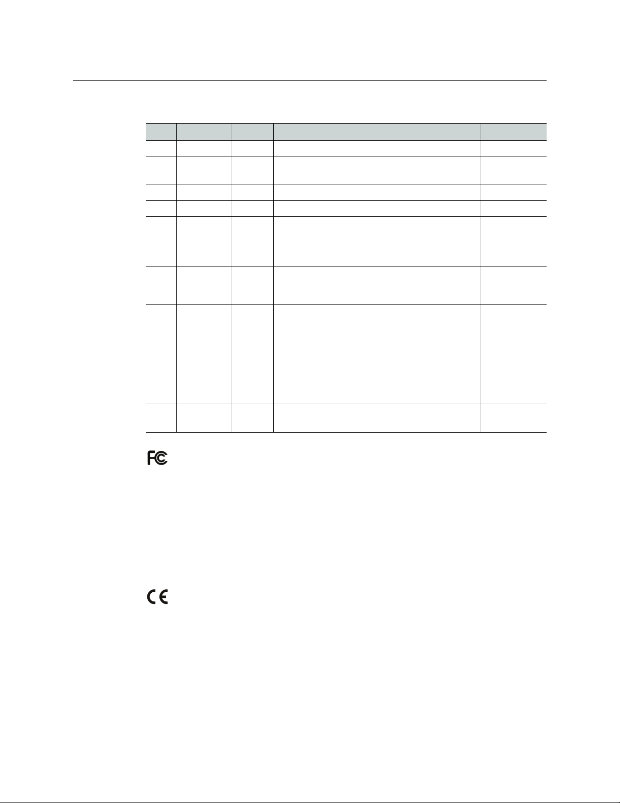
Change History
Rev Date ECO Description of Changes Approved By
1.0 28 Aug 06 — Initial Release D.Cox
2.0 17 Oct 08 14426 Created online help system. Updated to match prod-
2.1 18 Feb 09 15573 Updates DEM
2.2 31 Mar 09 15703 Format change. D.Cox
2.3 12 Jan 10 16272 Added NV9642, dynamic configuration updates,
3.0 18 Aug 10 17186 Updated for versions 5.3.x, 5.4.x and 6.0.0; tieline
4.0 05 Feb 11 17412 Added NV9642, dynamic configuration updates,
5.0 02 Dec 14 19357 Format change. Conforms to software version 6.4.5.
NV9000-SE Utilities
User’s Guide
DEM
uct updates.
DEM
serial control of SMS7000 (and bridges), global navigation buttons, Klotz serial protocol, remote machine
control routing.
DEM
groups; import and export data; changes to system
management; name sets
DEM
serial control of SMS7000 (and bridges), global navigation buttons, Klotz serial protocol, remote machine
control routing.
Updated import and export data; changes to system
management; name sets.
Added tieline groups; changes to multi-destination
dialog box; added VLE and VLC options
D.Cox
Added panels. Almost entirely re-written.
FCC Statement
This equipment has been tested and found to comply with the limits for a Class A digital
device, pursuant to part 15 of the FCC Rules. These limits are designed to provide reasonable
protection against harmful interference when the equipment is operated in a commercial
environment. This equipment generates, uses, and can radiate radio frequency energy and,
if not installed and used in accordance with the instruction manual, may cause harmful
interference to radio communications. Operation of this equipment in a residential area is
likely to cause harmful interference in which case the user will be required to correct the
interference at his own expense.
Declaration of Conformance (CE)
All of the equipment described in this manual has been designed to conform with the
required safety and emissions standards of the European Community. Products tested and
verified to meet these standards are marked as required by law with the CE mark.
When shipped into member countries of the European Community, this equipment is
accompanied by authentic copies of original Declarations of Conformance on file in the
Grass Valley offices in Grass Valley, California USA.
iii
Page 4

Software License Agreement and Warranty Information
Contact Grass Valley for details on the software license agreement and product warranty.
Important Safeguards and Notices
This section provides important safety guidelines for operators and service personnel.
Specific warnings and cautions appear throughout the manual where they apply. Please
read and follow this important information, especially those instructions related to the risk
of electric shock or injury to persons.
WAR NIN G
Any instructions in this manual that require opening the equipment cover or enclosure are
for use by qualified service personnel only. To reduce the risk of electric shock, do not
perform any service other than that contained in the operating instructions unless you are
qualified to do so.
Restriction on Hazardous Substances (RoHs)
Grass Valley is in compliance with EU Directive RoHS 2002/95/EC governing the restricted
use of certain hazardous substances and materials in products and in our manufacturing
processes.
Grass Valley has a substantial program in place for RoHS compliance that includes significant
investment in our manufacturing process, and a migration of Grass Valley product electronic
components and structural materials to RoHS compliance.
It is our objective at Grass Valley to maintain compliance with all relevant environmental and
product regulatory requirements. Detailed information on specific products or on the RoHS
program at Grass Valley is available from Grass Valley Customer Support at
1-800-719-1900 (toll-free) or
1-530-265-1000 (outside the U.S.).
iv
Page 5
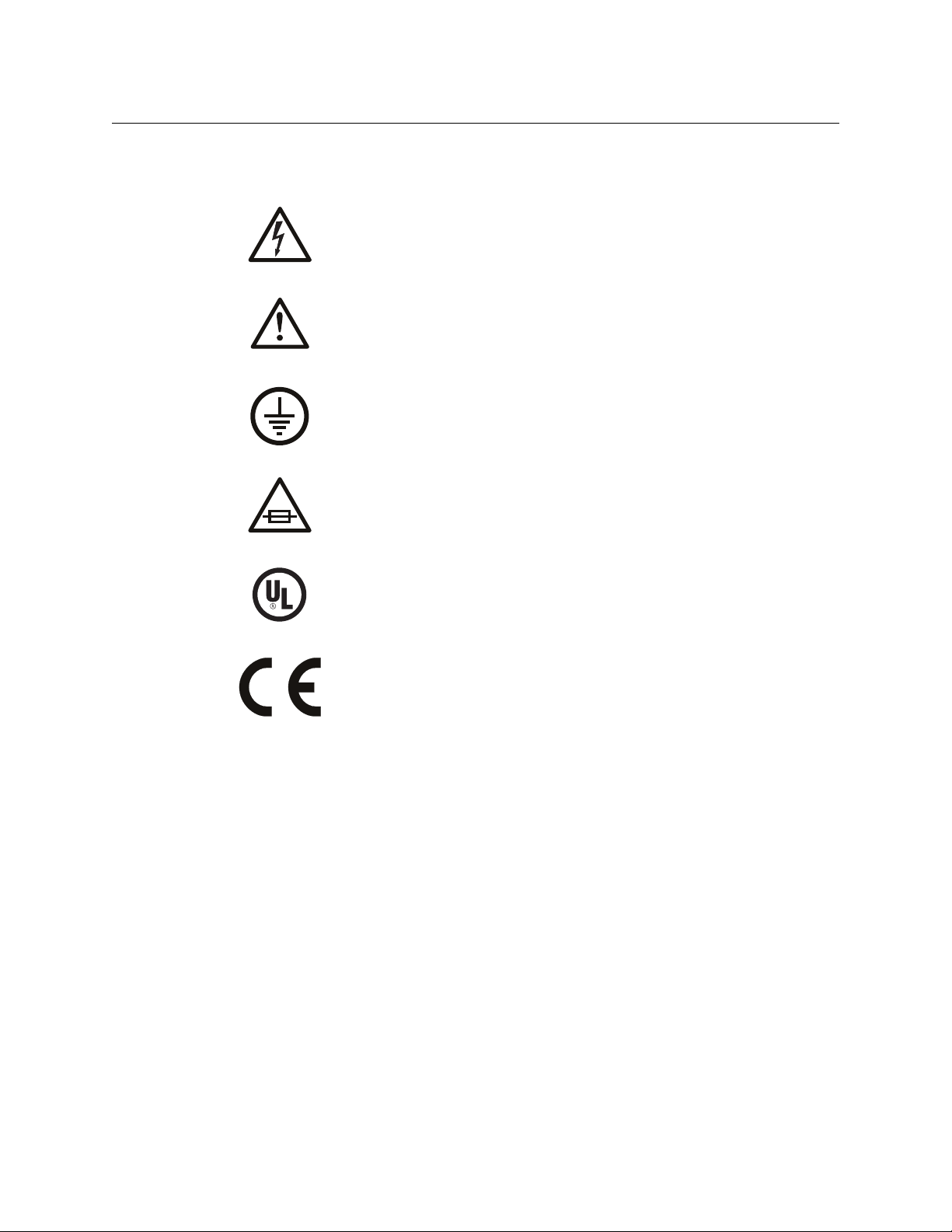
Symbols and Their Meanings
The lightning flash with arrowhead symbol within an equilateral triangle alerts the
user to the presence of dangerous voltages within the product’s enclosure that
may be of sufficient magnitude to constitute a risk of electric shock to persons.
The exclamation point within an equilateral triangle alerts the user to the presence
of important operating and maintenance/service instructions.
The Ground symbol represents a protective grounding terminal. Such a terminal
must be connected to earth ground prior to making any other connections to the
equipment.
The fuse symbol indicates that the fuse referenced in the text must be replaced
with one having the ratings indicated.
NV9000-SE Utilities
User’s Guide
The presence of this symbol in or on Grass Valley equipment means that it has been
designed, tested and certified as complying with applicable Underwriter’s
Laboratory (USA) regulations and recommendations.
The presence of this symbol in or on Grass Valley equipment means that it has been
designed, tested and certified as essentially complying with all applicable
European Union (CE) regulations and recommendations.
General Warnings
A warning indicates a possible hazard to personnel which may cause injury or death.
Observe the following general warnings when using or working on this equipment:
• Heed all warnings on the unit and in the operating instructions.
• Do not use this equipment in or near water.
• This equipment is grounded through the grounding conductor of the power cord. To
avoid electrical shock, plug the power cord into a properly wired receptacle before connecting the equipment inputs or outputs.
• Route power cords and other cables so they are not likely to be damaged.
• Disconnect power before cleaning the equipment. Do not use liquid or aerosol cleaners; use only a damp cloth.
• Dangerous voltages may exist at several points in this equipment. To avoid injury, do
not touch exposed connections and components while power is on.
• Do not wear rings or wristwatches when troubleshooting high current circuits such as
the power supplies.
v
Page 6

• To avoid fire hazard, use only the specified fuse(s) with the correct type number, voltage
and current ratings as referenced in the appropriate locations in the service instructions or on the equipment. Always refer fuse replacements to qualified service personnel.
• To avoid explosion, do not operate this equipment in an explosive atmosphere.
• Have qualified service personnel perform safety checks after any service.
General Cautions
A caution indicates a possible hazard to equipment that could result in equipment damage.
Observe the following cautions when operating or working on this equipment:
• When installing this equipment, do not attach the power cord to building surfaces.
• To prevent damage to equipment when replacing fuses, locate and correct the problem
that caused the fuse to blow before re-applying power.
• Use only the specified replacement parts.
• Follow static precautions at all times when handling this equipment.
• This product should only be powered as described in the manual. To prevent equipment damage, select the proper line voltage on the power supply(ies) as described in
the installation documentation.
• To prevent damage to the equipment, read the instructions in the equipment manual
for proper input voltage range selection.
• Some products include a backup battery. There is a risk of explosion if the battery is
replaced by a battery of an incorrect type. Dispose of batteries according to instructions.
• Products that have (1) no on/off switch and (2) use an external power supply must be
installed in proximity to a main power outlet that is easily accessible.
• To reduce the risk of electrical shock, plug each power supply cord into a separate
branch circuit having a separate service ground.
vi
Page 7

Table of Contents
1 Introduction . . . . . . . . . . . . . . . . . . . . . . . . . . . . . . . . . . . . . . . . . . . 1
Summary . . . . . . . . . . . . . . . . . . . . . . . . . . . . . . . . . . . . . . . . . . . . . . . . . . . . . . . . . . . . . . . . . . . . . . . . . . . . . . . . . . . . . . . 1
Usage . . . . . . . . . . . . . . . . . . . . . . . . . . . . . . . . . . . . . . . . . . . . . . . . . . . . . . . . . . . . . . . . . . . . . . . . . . . . . . . . . . . . . . . . . . 3
User Interface Basics . . . . . . . . . . . . . . . . . . . . . . . . . . . . . . . . . . . . . . . . . . . . . . . . . . . . . . . . . . . . . . . . . . . . . . . . . . . . 4
Launching NV9000-SE Utilities . . . . . . . . . . . . . . . . . . . . . . . . . . . . . . . . . . . . . . . . . . . . . . . . . . . . . . . . . . . . . . 4
Layout . . . . . . . . . . . . . . . . . . . . . . . . . . . . . . . . . . . . . . . . . . . . . . . . . . . . . . . . . . . . . . . . . . . . . . . . . . . . . . . . . . . . . 5
Configuration Pane. . . . . . . . . . . . . . . . . . . . . . . . . . . . . . . . . . . . . . . . . . . . . . . . . . . . . . . . . . . . . . . . . . . . . . . . . 6
Tasks Pane . . . . . . . . . . . . . . . . . . . . . . . . . . . . . . . . . . . . . . . . . . . . . . . . . . . . . . . . . . . . . . . . . . . . . . . . . . . . . . . . . 6
Views Pane. . . . . . . . . . . . . . . . . . . . . . . . . . . . . . . . . . . . . . . . . . . . . . . . . . . . . . . . . . . . . . . . . . . . . . . . . . . . . . . . . 6
System Management Pane . . . . . . . . . . . . . . . . . . . . . . . . . . . . . . . . . . . . . . . . . . . . . . . . . . . . . . . . . . . . . . . . . 7
Menus . . . . . . . . . . . . . . . . . . . . . . . . . . . . . . . . . . . . . . . . . . . . . . . . . . . . . . . . . . . . . . . . . . . . . . . . . . . . . . . . . . . . . . . . . 11
File Menu . . . . . . . . . . . . . . . . . . . . . . . . . . . . . . . . . . . . . . . . . . . . . . . . . . . . . . . . . . . . . . . . . . . . . . . . . . . . . . . . . 11
System Menu . . . . . . . . . . . . . . . . . . . . . . . . . . . . . . . . . . . . . . . . . . . . . . . . . . . . . . . . . . . . . . . . . . . . . . . . . . . . . 11
Window Menu . . . . . . . . . . . . . . . . . . . . . . . . . . . . . . . . . . . . . . . . . . . . . . . . . . . . . . . . . . . . . . . . . . . . . . . . . . . . 12
Help Menu . . . . . . . . . . . . . . . . . . . . . . . . . . . . . . . . . . . . . . . . . . . . . . . . . . . . . . . . . . . . . . . . . . . . . . . . . . . . . . . . 12
Using Tables . . . . . . . . . . . . . . . . . . . . . . . . . . . . . . . . . . . . . . . . . . . . . . . . . . . . . . . . . . . . . . . . . . . . . . . . . . . . . . . . . . . 12
Table Ordering . . . . . . . . . . . . . . . . . . . . . . . . . . . . . . . . . . . . . . . . . . . . . . . . . . . . . . . . . . . . . . . . . . . . . . . . . . . . 14
Table Shortcuts . . . . . . . . . . . . . . . . . . . . . . . . . . . . . . . . . . . . . . . . . . . . . . . . . . . . . . . . . . . . . . . . . . . . . . . . . . . 14
Shortcuts . . . . . . . . . . . . . . . . . . . . . . . . . . . . . . . . . . . . . . . . . . . . . . . . . . . . . . . . . . . . . . . . . . . . . . . . . . . . . . . . . . . . . . 15
Double-Click Option. . . . . . . . . . . . . . . . . . . . . . . . . . . . . . . . . . . . . . . . . . . . . . . . . . . . . . . . . . . . . . . . . . . . . . . 15
File Menu . . . . . . . . . . . . . . . . . . . . . . . . . . . . . . . . . . . . . . . . . . . . . . . . . . . . . . . . . . . . . . . . . . . . . . . . . . . . . . . . . 15
When Configuring a Control Panel . . . . . . . . . . . . . . . . . . . . . . . . . . . . . . . . . . . . . . . . . . . . . . . . . . . . . . . . . 16
What to Do and When to Do It. . . . . . . . . . . . . . . . . . . . . . . . . . . . . . . . . . . . . . . . . . . . . . . . . . . . . . . . . . . . . . . . . . 17
Configuration Steps . . . . . . . . . . . . . . . . . . . . . . . . . . . . . . . . . . . . . . . . . . . . . . . . . . . . . . . . . . . . . . . . . . . . . . . 17
2 Menus . . . . . . . . . . . . . . . . . . . . . . . . . . . . . . . . . . . . . . . . . . . . . . . . 19
Summary . . . . . . . . . . . . . . . . . . . . . . . . . . . . . . . . . . . . . . . . . . . . . . . . . . . . . . . . . . . . . . . . . . . . . . . . . . . . . . . . . . . . . . 19
File Menu . . . . . . . . . . . . . . . . . . . . . . . . . . . . . . . . . . . . . . . . . . . . . . . . . . . . . . . . . . . . . . . . . . . . . . . . . . . . . . . . . . . . . 19
System Menu . . . . . . . . . . . . . . . . . . . . . . . . . . . . . . . . . . . . . . . . . . . . . . . . . . . . . . . . . . . . . . . . . . . . . . . . . . . . . . . . . . 26
Window Menu . . . . . . . . . . . . . . . . . . . . . . . . . . . . . . . . . . . . . . . . . . . . . . . . . . . . . . . . . . . . . . . . . . . . . . . . . . . . . . . . . 27
Help Menu. . . . . . . . . . . . . . . . . . . . . . . . . . . . . . . . . . . . . . . . . . . . . . . . . . . . . . . . . . . . . . . . . . . . . . . . . . . . . . . . . . . . . 28
3 Installation. . . . . . . . . . . . . . . . . . . . . . . . . . . . . . . . . . . . . . . . . . . . 29
From the CD . . . . . . . . . . . . . . . . . . . . . . . . . . . . . . . . . . . . . . . . . . . . . . . . . . . . . . . . . . . . . . . . . . . . . . . . . . . . . . . . . . . 29
Without the CD . . . . . . . . . . . . . . . . . . . . . . . . . . . . . . . . . . . . . . . . . . . . . . . . . . . . . . . . . . . . . . . . . . . . . . . . . . . . . . . . 30
In Either Case . . . . . . . . . . . . . . . . . . . . . . . . . . . . . . . . . . . . . . . . . . . . . . . . . . . . . . . . . . . . . . . . . . . . . . . . . . . . . . . . . . 31
4 Routers . . . . . . . . . . . . . . . . . . . . . . . . . . . . . . . . . . . . . . . . . . . . . . . 35
Introduction to NVISION Series Routers . . . . . . . . . . . . . . . . . . . . . . . . . . . . . . . . . . . . . . . . . . . . . . . . . . . . . . . . . 35
Large-Format Routers . . . . . . . . . . . . . . . . . . . . . . . . . . . . . . . . . . . . . . . . . . . . . . . . . . . . . . . . . . . . . . . . . . . . . 35
Compact Routers. . . . . . . . . . . . . . . . . . . . . . . . . . . . . . . . . . . . . . . . . . . . . . . . . . . . . . . . . . . . . . . . . . . . . . . . . . 36
Definitions . . . . . . . . . . . . . . . . . . . . . . . . . . . . . . . . . . . . . . . . . . . . . . . . . . . . . . . . . . . . . . . . . . . . . . . . . . . . . . . . 36
Router Configuration in NV9000-SE Utilities. . . . . . . . . . . . . . . . . . . . . . . . . . . . . . . . . . . . . . . . . . . . . . . . . . . . . 38
vii
Page 8

Table of Contents
‘Routers’ page . . . . . . . . . . . . . . . . . . . . . . . . . . . . . . . . . . . . . . . . . . . . . . . . . . . . . . . . . . . . . . . . . . . . . . . . . . . . . . . . . 39
Router List . . . . . . . . . . . . . . . . . . . . . . . . . . . . . . . . . . . . . . . . . . . . . . . . . . . . . . . . . . . . . . . . . . . . . . . . . . . . . . . . 39
‘Edit Selected Routers’ Button . . . . . . . . . . . . . . . . . . . . . . . . . . . . . . . . . . . . . . . . . . . . . . . . . . . . . . . . . . . . . 39
‘Add Router’ Button . . . . . . . . . . . . . . . . . . . . . . . . . . . . . . . . . . . . . . . . . . . . . . . . . . . . . . . . . . . . . . . . . . . . . . . 40
‘Delete Router’ Button. . . . . . . . . . . . . . . . . . . . . . . . . . . . . . . . . . . . . . . . . . . . . . . . . . . . . . . . . . . . . . . . . . . . . 40
‘Add Router’ page. . . . . . . . . . . . . . . . . . . . . . . . . . . . . . . . . . . . . . . . . . . . . . . . . . . . . . . . . . . . . . . . . . . . . . . . . . . . . . 40
Name . . . . . . . . . . . . . . . . . . . . . . . . . . . . . . . . . . . . . . . . . . . . . . . . . . . . . . . . . . . . . . . . . . . . . . . . . . . . . . . . . . . . . 42
Router Host . . . . . . . . . . . . . . . . . . . . . . . . . . . . . . . . . . . . . . . . . . . . . . . . . . . . . . . . . . . . . . . . . . . . . . . . . . . . . . . 42
Protocol . . . . . . . . . . . . . . . . . . . . . . . . . . . . . . . . . . . . . . . . . . . . . . . . . . . . . . . . . . . . . . . . . . . . . . . . . . . . . . . . . . 42
Control Points. . . . . . . . . . . . . . . . . . . . . . . . . . . . . . . . . . . . . . . . . . . . . . . . . . . . . . . . . . . . . . . . . . . . . . . . . . . . . 42
‘Previous’ Button . . . . . . . . . . . . . . . . . . . . . . . . . . . . . . . . . . . . . . . . . . . . . . . . . . . . . . . . . . . . . . . . . . . . . . . . . . 43
‘Next’ Button . . . . . . . . . . . . . . . . . . . . . . . . . . . . . . . . . . . . . . . . . . . . . . . . . . . . . . . . . . . . . . . . . . . . . . . . . . . . . . 43
‘Finish’ Button. . . . . . . . . . . . . . . . . . . . . . . . . . . . . . . . . . . . . . . . . . . . . . . . . . . . . . . . . . . . . . . . . . . . . . . . . . . . . 44
‘Cancel’ Button . . . . . . . . . . . . . . . . . . . . . . . . . . . . . . . . . . . . . . . . . . . . . . . . . . . . . . . . . . . . . . . . . . . . . . . . . . . . 44
Router Details Page . . . . . . . . . . . . . . . . . . . . . . . . . . . . . . . . . . . . . . . . . . . . . . . . . . . . . . . . . . . . . . . . . . . . . . . . . . . . 45
Router Information . . . . . . . . . . . . . . . . . . . . . . . . . . . . . . . . . . . . . . . . . . . . . . . . . . . . . . . . . . . . . . . . . . . . . . . . 46
Control Point Information . . . . . . . . . . . . . . . . . . . . . . . . . . . . . . . . . . . . . . . . . . . . . . . . . . . . . . . . . . . . . . . . . 46
Detailed Router Information . . . . . . . . . . . . . . . . . . . . . . . . . . . . . . . . . . . . . . . . . . . . . . . . . . . . . . . . . . . . . . . 47
‘Routers’ table . . . . . . . . . . . . . . . . . . . . . . . . . . . . . . . . . . . . . . . . . . . . . . . . . . . . . . . . . . . . . . . . . . . . . . . . . . . . . . . . . 50
‘Router Controls’ table . . . . . . . . . . . . . . . . . . . . . . . . . . . . . . . . . . . . . . . . . . . . . . . . . . . . . . . . . . . . . . . . . . . . . . . . . 51
Filters . . . . . . . . . . . . . . . . . . . . . . . . . . . . . . . . . . . . . . . . . . . . . . . . . . . . . . . . . . . . . . . . . . . . . . . . . . . . . . . . . . . . . 51
Router List . . . . . . . . . . . . . . . . . . . . . . . . . . . . . . . . . . . . . . . . . . . . . . . . . . . . . . . . . . . . . . . . . . . . . . . . . . . . . . . . 52
Buttons . . . . . . . . . . . . . . . . . . . . . . . . . . . . . . . . . . . . . . . . . . . . . . . . . . . . . . . . . . . . . . . . . . . . . . . . . . . . . . . . . . . 52
Modifying the Table Data. . . . . . . . . . . . . . . . . . . . . . . . . . . . . . . . . . . . . . . . . . . . . . . . . . . . . . . . . . . . . . . . . . 53
DHP Data in the Router Tables . . . . . . . . . . . . . . . . . . . . . . . . . . . . . . . . . . . . . . . . . . . . . . . . . . . . . . . . . . . . . 53
Control Points table . . . . . . . . . . . . . . . . . . . . . . . . . . . . . . . . . . . . . . . . . . . . . . . . . . . . . . . . . . . . . . . . . . . . . . . . . . . . 55
Filters . . . . . . . . . . . . . . . . . . . . . . . . . . . . . . . . . . . . . . . . . . . . . . . . . . . . . . . . . . . . . . . . . . . . . . . . . . . . . . . . . . . . . 56
Control Point List. . . . . . . . . . . . . . . . . . . . . . . . . . . . . . . . . . . . . . . . . . . . . . . . . . . . . . . . . . . . . . . . . . . . . . . . . . 56
Buttons . . . . . . . . . . . . . . . . . . . . . . . . . . . . . . . . . . . . . . . . . . . . . . . . . . . . . . . . . . . . . . . . . . . . . . . . . . . . . . . . . . . 57
‘View Router Ports’ page . . . . . . . . . . . . . . . . . . . . . . . . . . . . . . . . . . . . . . . . . . . . . . . . . . . . . . . . . . . . . . . . . . . . . . . 58
‘Find Routers’ page. . . . . . . . . . . . . . . . . . . . . . . . . . . . . . . . . . . . . . . . . . . . . . . . . . . . . . . . . . . . . . . . . . . . . . . . . . . . . 59
Virtual Crosspoints . . . . . . . . . . . . . . . . . . . . . . . . . . . . . . . . . . . . . . . . . . . . . . . . . . . . . . . . . . . . . . . . . . . . . . . . . . . . . 59
Principles . . . . . . . . . . . . . . . . . . . . . . . . . . . . . . . . . . . . . . . . . . . . . . . . . . . . . . . . . . . . . . . . . . . . . . . . . . . . . . . . . 60
NVISION Profiles . . . . . . . . . . . . . . . . . . . . . . . . . . . . . . . . . . . . . . . . . . . . . . . . . . . . . . . . . . . . . . . . . . . . . . . . . . . . . . . 63
Creating a “Profile” . . . . . . . . . . . . . . . . . . . . . . . . . . . . . . . . . . . . . . . . . . . . . . . . . . . . . . . . . . . . . . . . . . . . . . . . 64
5 System Management . . . . . . . . . . . . . . . . . . . . . . . . . . . . . . . . . . 67
Summary . . . . . . . . . . . . . . . . . . . . . . . . . . . . . . . . . . . . . . . . . . . . . . . . . . . . . . . . . . . . . . . . . . . . . . . . . . . . . . . . . . . . . . 67
Hovering. . . . . . . . . . . . . . . . . . . . . . . . . . . . . . . . . . . . . . . . . . . . . . . . . . . . . . . . . . . . . . . . . . . . . . . . . . . . . . . . . . 69
Context Menu. . . . . . . . . . . . . . . . . . . . . . . . . . . . . . . . . . . . . . . . . . . . . . . . . . . . . . . . . . . . . . . . . . . . . . . . . . . . . 70
Managing Control Systems . . . . . . . . . . . . . . . . . . . . . . . . . . . . . . . . . . . . . . . . . . . . . . . . . . . . . . . . . . . . . . . . . . . . . 70
Main System Page . . . . . . . . . . . . . . . . . . . . . . . . . . . . . . . . . . . . . . . . . . . . . . . . . . . . . . . . . . . . . . . . . . . . . . . . . . . . . 71
Controller Summary. . . . . . . . . . . . . . . . . . . . . . . . . . . . . . . . . . . . . . . . . . . . . . . . . . . . . . . . . . . . . . . . . . . . . . . 71
Router Summary . . . . . . . . . . . . . . . . . . . . . . . . . . . . . . . . . . . . . . . . . . . . . . . . . . . . . . . . . . . . . . . . . . . . . . . . . . 72
Panel Summary . . . . . . . . . . . . . . . . . . . . . . . . . . . . . . . . . . . . . . . . . . . . . . . . . . . . . . . . . . . . . . . . . . . . . . . . . . . 72
External Interface Summary . . . . . . . . . . . . . . . . . . . . . . . . . . . . . . . . . . . . . . . . . . . . . . . . . . . . . . . . . . . . . . . 72
License Summary . . . . . . . . . . . . . . . . . . . . . . . . . . . . . . . . . . . . . . . . . . . . . . . . . . . . . . . . . . . . . . . . . . . . . . . . . 73
Buttons . . . . . . . . . . . . . . . . . . . . . . . . . . . . . . . . . . . . . . . . . . . . . . . . . . . . . . . . . . . . . . . . . . . . . . . . . . . . . . . . . . . 73
System Log Page. . . . . . . . . . . . . . . . . . . . . . . . . . . . . . . . . . . . . . . . . . . . . . . . . . . . . . . . . . . . . . . . . . . . . . . . . . . . . . . 77
Options . . . . . . . . . . . . . . . . . . . . . . . . . . . . . . . . . . . . . . . . . . . . . . . . . . . . . . . . . . . . . . . . . . . . . . . . . . . . . . . . . . . 77
Filters . . . . . . . . . . . . . . . . . . . . . . . . . . . . . . . . . . . . . . . . . . . . . . . . . . . . . . . . . . . . . . . . . . . . . . . . . . . . . . . . . . . . . 78
Export to File. . . . . . . . . . . . . . . . . . . . . . . . . . . . . . . . . . . . . . . . . . . . . . . . . . . . . . . . . . . . . . . . . . . . . . . . . . . . . . 79
Routers Page. . . . . . . . . . . . . . . . . . . . . . . . . . . . . . . . . . . . . . . . . . . . . . . . . . . . . . . . . . . . . . . . . . . . . . . . . . . . . . . . . . . 80
Display Controls. . . . . . . . . . . . . . . . . . . . . . . . . . . . . . . . . . . . . . . . . . . . . . . . . . . . . . . . . . . . . . . . . . . . . . . . . . . 81
Take Control . . . . . . . . . . . . . . . . . . . . . . . . . . . . . . . . . . . . . . . . . . . . . . . . . . . . . . . . . . . . . . . . . . . . . . . . . . . . . . 81
viii
Page 9

LPR Controls . . . . . . . . . . . . . . . . . . . . . . . . . . . . . . . . . . . . . . . . . . . . . . . . . . . . . . . . . . . . . . . . . . . . . . . . . . . . . . 81
Crosspoint Display . . . . . . . . . . . . . . . . . . . . . . . . . . . . . . . . . . . . . . . . . . . . . . . . . . . . . . . . . . . . . . . . . . . . . . . . 83
Control Panels Page. . . . . . . . . . . . . . . . . . . . . . . . . . . . . . . . . . . . . . . . . . . . . . . . . . . . . . . . . . . . . . . . . . . . . . . . . . . . 84
Panel List . . . . . . . . . . . . . . . . . . . . . . . . . . . . . . . . . . . . . . . . . . . . . . . . . . . . . . . . . . . . . . . . . . . . . . . . . . . . . . . . . 84
Buttons . . . . . . . . . . . . . . . . . . . . . . . . . . . . . . . . . . . . . . . . . . . . . . . . . . . . . . . . . . . . . . . . . . . . . . . . . . . . . . . . . . . 85
Tieline Status Page . . . . . . . . . . . . . . . . . . . . . . . . . . . . . . . . . . . . . . . . . . . . . . . . . . . . . . . . . . . . . . . . . . . . . . . . . . . . . 86
Tieline Usage. . . . . . . . . . . . . . . . . . . . . . . . . . . . . . . . . . . . . . . . . . . . . . . . . . . . . . . . . . . . . . . . . . . . . . . . . . . . . . 86
Tieline Graph. . . . . . . . . . . . . . . . . . . . . . . . . . . . . . . . . . . . . . . . . . . . . . . . . . . . . . . . . . . . . . . . . . . . . . . . . . . . . . 87
Navigation Pane . . . . . . . . . . . . . . . . . . . . . . . . . . . . . . . . . . . . . . . . . . . . . . . . . . . . . . . . . . . . . . . . . . . . . . . . . . . . . . . 88
Add Control System . . . . . . . . . . . . . . . . . . . . . . . . . . . . . . . . . . . . . . . . . . . . . . . . . . . . . . . . . . . . . . . . . . . . . . . 88
Edit This Control System. . . . . . . . . . . . . . . . . . . . . . . . . . . . . . . . . . . . . . . . . . . . . . . . . . . . . . . . . . . . . . . . . . . 89
Ignore This Control System . . . . . . . . . . . . . . . . . . . . . . . . . . . . . . . . . . . . . . . . . . . . . . . . . . . . . . . . . . . . . . . . 90
Remove This Control System . . . . . . . . . . . . . . . . . . . . . . . . . . . . . . . . . . . . . . . . . . . . . . . . . . . . . . . . . . . . . . 90
Edit/View DHCP . . . . . . . . . . . . . . . . . . . . . . . . . . . . . . . . . . . . . . . . . . . . . . . . . . . . . . . . . . . . . . . . . . . . . . . . . . . 91
Edit/View SNMP . . . . . . . . . . . . . . . . . . . . . . . . . . . . . . . . . . . . . . . . . . . . . . . . . . . . . . . . . . . . . . . . . . . . . . . . . . . 92
Set/Change Virtual IP. . . . . . . . . . . . . . . . . . . . . . . . . . . . . . . . . . . . . . . . . . . . . . . . . . . . . . . . . . . . . . . . . . . . . . 93
Load Snapshot from . . .. . . . . . . . . . . . . . . . . . . . . . . . . . . . . . . . . . . . . . . . . . . . . . . . . . . . . . . . . . . . . . . . . . . . 93
Save Snapshot to . . .. . . . . . . . . . . . . . . . . . . . . . . . . . . . . . . . . . . . . . . . . . . . . . . . . . . . . . . . . . . . . . . . . . . . . . . 94
Edit Name Sets . . . . . . . . . . . . . . . . . . . . . . . . . . . . . . . . . . . . . . . . . . . . . . . . . . . . . . . . . . . . . . . . . . . . . . . . . . . . 95
Convert to Tieline Status GUI . . . . . . . . . . . . . . . . . . . . . . . . . . . . . . . . . . . . . . . . . . . . . . . . . . . . . . . . . . . . . . 99
Generate Difference Report. . . . . . . . . . . . . . . . . . . . . . . . . . . . . . . . . . . . . . . . . . . . . . . . . . . . . . . . . . . . . . . 100
Other Topics . . . . . . . . . . . . . . . . . . . . . . . . . . . . . . . . . . . . . . . . . . . . . . . . . . . . . . . . . . . . . . . . . . . . . . . . . . . . . . . . . . 102
Analyze Configuration. . . . . . . . . . . . . . . . . . . . . . . . . . . . . . . . . . . . . . . . . . . . . . . . . . . . . . . . . . . . . . . . . . . . 102
System Controllers . . . . . . . . . . . . . . . . . . . . . . . . . . . . . . . . . . . . . . . . . . . . . . . . . . . . . . . . . . . . . . . . . . . . . . . 102
IP Addresses . . . . . . . . . . . . . . . . . . . . . . . . . . . . . . . . . . . . . . . . . . . . . . . . . . . . . . . . . . . . . . . . . . . . . . . . . . . . . 105
Licenses . . . . . . . . . . . . . . . . . . . . . . . . . . . . . . . . . . . . . . . . . . . . . . . . . . . . . . . . . . . . . . . . . . . . . . . . . . . . . . . . . 106
DHP . . . . . . . . . . . . . . . . . . . . . . . . . . . . . . . . . . . . . . . . . . . . . . . . . . . . . . . . . . . . . . . . . . . . . . . . . . . . . . . . . . . . . 106
SNMP . . . . . . . . . . . . . . . . . . . . . . . . . . . . . . . . . . . . . . . . . . . . . . . . . . . . . . . . . . . . . . . . . . . . . . . . . . . . . . . . . . . . 107
Tielines . . . . . . . . . . . . . . . . . . . . . . . . . . . . . . . . . . . . . . . . . . . . . . . . . . . . . . . . . . . . . . . . . . . . . . . . . . . . . . . . . . 107
Database Repository . . . . . . . . . . . . . . . . . . . . . . . . . . . . . . . . . . . . . . . . . . . . . . . . . . . . . . . . . . . . . . . . . . . . . 107
Hosts . . . . . . . . . . . . . . . . . . . . . . . . . . . . . . . . . . . . . . . . . . . . . . . . . . . . . . . . . . . . . . . . . . . . . . . . . . . . . . . . . . . . 108
Panel IDs. . . . . . . . . . . . . . . . . . . . . . . . . . . . . . . . . . . . . . . . . . . . . . . . . . . . . . . . . . . . . . . . . . . . . . . . . . . . . . . . . 108
Master Control . . . . . . . . . . . . . . . . . . . . . . . . . . . . . . . . . . . . . . . . . . . . . . . . . . . . . . . . . . . . . . . . . . . . . . . . . . . 108
Kaleido . . . . . . . . . . . . . . . . . . . . . . . . . . . . . . . . . . . . . . . . . . . . . . . . . . . . . . . . . . . . . . . . . . . . . . . . . . . . . . . . . . 108
NV9700 . . . . . . . . . . . . . . . . . . . . . . . . . . . . . . . . . . . . . . . . . . . . . . . . . . . . . . . . . . . . . . . . . . . . . . . . . . . . . . . . . . 109
NV9000 Web Suite . . . . . . . . . . . . . . . . . . . . . . . . . . . . . . . . . . . . . . . . . . . . . . . . . . . . . . . . . . . . . . . . . . . . . . . 109
UniConfig
User’s Guide
6 Virtual Levels and Level Sets . . . . . . . . . . . . . . . . . . . . . . . . . .111
Introduction . . . . . . . . . . . . . . . . . . . . . . . . . . . . . . . . . . . . . . . . . . . . . . . . . . . . . . . . . . . . . . . . . . . . . . . . . . . . . . . . . . 111
Level Sets . . . . . . . . . . . . . . . . . . . . . . . . . . . . . . . . . . . . . . . . . . . . . . . . . . . . . . . . . . . . . . . . . . . . . . . . . . . . . . . . 112
Virtual Level Groups . . . . . . . . . . . . . . . . . . . . . . . . . . . . . . . . . . . . . . . . . . . . . . . . . . . . . . . . . . . . . . . . . . . . . . 112
Levels at Control Panels . . . . . . . . . . . . . . . . . . . . . . . . . . . . . . . . . . . . . . . . . . . . . . . . . . . . . . . . . . . . . . . . . . 113
Notes . . . . . . . . . . . . . . . . . . . . . . . . . . . . . . . . . . . . . . . . . . . . . . . . . . . . . . . . . . . . . . . . . . . . . . . . . . . . . . . . . . . . 114
Example . . . . . . . . . . . . . . . . . . . . . . . . . . . . . . . . . . . . . . . . . . . . . . . . . . . . . . . . . . . . . . . . . . . . . . . . . . . . . . . . . 114
Pages and Tables. . . . . . . . . . . . . . . . . . . . . . . . . . . . . . . . . . . . . . . . . . . . . . . . . . . . . . . . . . . . . . . . . . . . . . . . . 114
‘Level Sets’ Page . . . . . . . . . . . . . . . . . . . . . . . . . . . . . . . . . . . . . . . . . . . . . . . . . . . . . . . . . . . . . . . . . . . . . . . . . . . . . . 116
Filter. . . . . . . . . . . . . . . . . . . . . . . . . . . . . . . . . . . . . . . . . . . . . . . . . . . . . . . . . . . . . . . . . . . . . . . . . . . . . . . . . . . . . 116
Level Set List . . . . . . . . . . . . . . . . . . . . . . . . . . . . . . . . . . . . . . . . . . . . . . . . . . . . . . . . . . . . . . . . . . . . . . . . . . . . . 116
Buttons . . . . . . . . . . . . . . . . . . . . . . . . . . . . . . . . . . . . . . . . . . . . . . . . . . . . . . . . . . . . . . . . . . . . . . . . . . . . . . . . . . 116
‘Add Level Set’ Page . . . . . . . . . . . . . . . . . . . . . . . . . . . . . . . . . . . . . . . . . . . . . . . . . . . . . . . . . . . . . . . . . . . . . . . . . . 118
‘Previous’ Button . . . . . . . . . . . . . . . . . . . . . . . . . . . . . . . . . . . . . . . . . . . . . . . . . . . . . . . . . . . . . . . . . . . . . . . . . 118
‘Next’ Button . . . . . . . . . . . . . . . . . . . . . . . . . . . . . . . . . . . . . . . . . . . . . . . . . . . . . . . . . . . . . . . . . . . . . . . . . . . . . 118
‘Finish’ Button. . . . . . . . . . . . . . . . . . . . . . . . . . . . . . . . . . . . . . . . . . . . . . . . . . . . . . . . . . . . . . . . . . . . . . . . . . . . 119
‘Cancel’ Button . . . . . . . . . . . . . . . . . . . . . . . . . . . . . . . . . . . . . . . . . . . . . . . . . . . . . . . . . . . . . . . . . . . . . . . . . . . 119
ix
Page 10

Table of Contents
Level Set Details Page . . . . . . . . . . . . . . . . . . . . . . . . . . . . . . . . . . . . . . . . . . . . . . . . . . . . . . . . . . . . . . . . . . . . . . . . 120
Name . . . . . . . . . . . . . . . . . . . . . . . . . . . . . . . . . . . . . . . . . . . . . . . . . . . . . . . . . . . . . . . . . . . . . . . . . . . . . . . . . . . . 120
Buttons . . . . . . . . . . . . . . . . . . . . . . . . . . . . . . . . . . . . . . . . . . . . . . . . . . . . . . . . . . . . . . . . . . . . . . . . . . . . . . . . . . 121
Level Set Detail. . . . . . . . . . . . . . . . . . . . . . . . . . . . . . . . . . . . . . . . . . . . . . . . . . . . . . . . . . . . . . . . . . . . . . . . . . . 121
Virtual Level Types . . . . . . . . . . . . . . . . . . . . . . . . . . . . . . . . . . . . . . . . . . . . . . . . . . . . . . . . . . . . . . . . . . . . . . . 122
‘Level Sets’ Table . . . . . . . . . . . . . . . . . . . . . . . . . . . . . . . . . . . . . . . . . . . . . . . . . . . . . . . . . . . . . . . . . . . . . . . . . . . . . 126
Filter. . . . . . . . . . . . . . . . . . . . . . . . . . . . . . . . . . . . . . . . . . . . . . . . . . . . . . . . . . . . . . . . . . . . . . . . . . . . . . . . . . . . . 126
Buttons . . . . . . . . . . . . . . . . . . . . . . . . . . . . . . . . . . . . . . . . . . . . . . . . . . . . . . . . . . . . . . . . . . . . . . . . . . . . . . . . . . 126
‘Level Set Details’ Table . . . . . . . . . . . . . . . . . . . . . . . . . . . . . . . . . . . . . . . . . . . . . . . . . . . . . . . . . . . . . . . . . . . . . . . 127
List of Virtual Levels . . . . . . . . . . . . . . . . . . . . . . . . . . . . . . . . . . . . . . . . . . . . . . . . . . . . . . . . . . . . . . . . . . . . . . 127
Filters . . . . . . . . . . . . . . . . . . . . . . . . . . . . . . . . . . . . . . . . . . . . . . . . . . . . . . . . . . . . . . . . . . . . . . . . . . . . . . . . . . . . 128
Buttons . . . . . . . . . . . . . . . . . . . . . . . . . . . . . . . . . . . . . . . . . . . . . . . . . . . . . . . . . . . . . . . . . . . . . . . . . . . . . . . . . . 128
‘Virtual Levels’ Table . . . . . . . . . . . . . . . . . . . . . . . . . . . . . . . . . . . . . . . . . . . . . . . . . . . . . . . . . . . . . . . . . . . . . . . . . . 129
Filter. . . . . . . . . . . . . . . . . . . . . . . . . . . . . . . . . . . . . . . . . . . . . . . . . . . . . . . . . . . . . . . . . . . . . . . . . . . . . . . . . . . . . 129
Buttons . . . . . . . . . . . . . . . . . . . . . . . . . . . . . . . . . . . . . . . . . . . . . . . . . . . . . . . . . . . . . . . . . . . . . . . . . . . . . . . . . . 130
‘Virtual Level Groups’ Table . . . . . . . . . . . . . . . . . . . . . . . . . . . . . . . . . . . . . . . . . . . . . . . . . . . . . . . . . . . . . . . . . . . 131
Filters . . . . . . . . . . . . . . . . . . . . . . . . . . . . . . . . . . . . . . . . . . . . . . . . . . . . . . . . . . . . . . . . . . . . . . . . . . . . . . . . . . . . 131
Buttons . . . . . . . . . . . . . . . . . . . . . . . . . . . . . . . . . . . . . . . . . . . . . . . . . . . . . . . . . . . . . . . . . . . . . . . . . . . . . . . . . . 132
‘Virtual Level Signal Binding’ Table . . . . . . . . . . . . . . . . . . . . . . . . . . . . . . . . . . . . . . . . . . . . . . . . . . . . . . . . . . . . 133
Filters . . . . . . . . . . . . . . . . . . . . . . . . . . . . . . . . . . . . . . . . . . . . . . . . . . . . . . . . . . . . . . . . . . . . . . . . . . . . . . . . . . . . 134
Buttons . . . . . . . . . . . . . . . . . . . . . . . . . . . . . . . . . . . . . . . . . . . . . . . . . . . . . . . . . . . . . . . . . . . . . . . . . . . . . . . . . . 134
‘Signal Type’ Table . . . . . . . . . . . . . . . . . . . . . . . . . . . . . . . . . . . . . . . . . . . . . . . . . . . . . . . . . . . . . . . . . . . . . . . . . . . . 135
Filter. . . . . . . . . . . . . . . . . . . . . . . . . . . . . . . . . . . . . . . . . . . . . . . . . . . . . . . . . . . . . . . . . . . . . . . . . . . . . . . . . . . . . 135
Buttons . . . . . . . . . . . . . . . . . . . . . . . . . . . . . . . . . . . . . . . . . . . . . . . . . . . . . . . . . . . . . . . . . . . . . . . . . . . . . . . . . . 136
Notes on Creating a Level Set. . . . . . . . . . . . . . . . . . . . . . . . . . . . . . . . . . . . . . . . . . . . . . . . . . . . . . . . . . . . . . . . . . 136
7 Devices and Device Categories . . . . . . . . . . . . . . . . . . . . . . . . 137
Introduction . . . . . . . . . . . . . . . . . . . . . . . . . . . . . . . . . . . . . . . . . . . . . . . . . . . . . . . . . . . . . . . . . . . . . . . . . . . . . . . . . . 137
Categories . . . . . . . . . . . . . . . . . . . . . . . . . . . . . . . . . . . . . . . . . . . . . . . . . . . . . . . . . . . . . . . . . . . . . . . . . . . . . . . 138
Level Sets . . . . . . . . . . . . . . . . . . . . . . . . . . . . . . . . . . . . . . . . . . . . . . . . . . . . . . . . . . . . . . . . . . . . . . . . . . . . . . . . 138
Configuration Pages and Tables . . . . . . . . . . . . . . . . . . . . . . . . . . . . . . . . . . . . . . . . . . . . . . . . . . . . . . . . . . 139
Devices Page . . . . . . . . . . . . . . . . . . . . . . . . . . . . . . . . . . . . . . . . . . . . . . . . . . . . . . . . . . . . . . . . . . . . . . . . . . . . . . . . . 139
Filters . . . . . . . . . . . . . . . . . . . . . . . . . . . . . . . . . . . . . . . . . . . . . . . . . . . . . . . . . . . . . . . . . . . . . . . . . . . . . . . . . . . . 140
Device List . . . . . . . . . . . . . . . . . . . . . . . . . . . . . . . . . . . . . . . . . . . . . . . . . . . . . . . . . . . . . . . . . . . . . . . . . . . . . . . 140
Buttons . . . . . . . . . . . . . . . . . . . . . . . . . . . . . . . . . . . . . . . . . . . . . . . . . . . . . . . . . . . . . . . . . . . . . . . . . . . . . . . . . . 140
Device Details Page . . . . . . . . . . . . . . . . . . . . . . . . . . . . . . . . . . . . . . . . . . . . . . . . . . . . . . . . . . . . . . . . . . . . . . . . . . . 142
Device Information Section. . . . . . . . . . . . . . . . . . . . . . . . . . . . . . . . . . . . . . . . . . . . . . . . . . . . . . . . . . . . . . . 142
Buttons . . . . . . . . . . . . . . . . . . . . . . . . . . . . . . . . . . . . . . . . . . . . . . . . . . . . . . . . . . . . . . . . . . . . . . . . . . . . . . . . . . 143
Device Detail — I/O Ports. . . . . . . . . . . . . . . . . . . . . . . . . . . . . . . . . . . . . . . . . . . . . . . . . . . . . . . . . . . . . . . . . 143
Level-to-Port Relationships . . . . . . . . . . . . . . . . . . . . . . . . . . . . . . . . . . . . . . . . . . . . . . . . . . . . . . . . . . . . . . . 144
Categories Page . . . . . . . . . . . . . . . . . . . . . . . . . . . . . . . . . . . . . . . . . . . . . . . . . . . . . . . . . . . . . . . . . . . . . . . . . . . . . . 144
Filters . . . . . . . . . . . . . . . . . . . . . . . . . . . . . . . . . . . . . . . . . . . . . . . . . . . . . . . . . . . . . . . . . . . . . . . . . . . . . . . . . . . . 145
Category List . . . . . . . . . . . . . . . . . . . . . . . . . . . . . . . . . . . . . . . . . . . . . . . . . . . . . . . . . . . . . . . . . . . . . . . . . . . . . 145
Buttons . . . . . . . . . . . . . . . . . . . . . . . . . . . . . . . . . . . . . . . . . . . . . . . . . . . . . . . . . . . . . . . . . . . . . . . . . . . . . . . . . . 145
Category Details Page . . . . . . . . . . . . . . . . . . . . . . . . . . . . . . . . . . . . . . . . . . . . . . . . . . . . . . . . . . . . . . . . . . . . . . . . 147
Category Information . . . . . . . . . . . . . . . . . . . . . . . . . . . . . . . . . . . . . . . . . . . . . . . . . . . . . . . . . . . . . . . . . . . . 148
Category Buttons . . . . . . . . . . . . . . . . . . . . . . . . . . . . . . . . . . . . . . . . . . . . . . . . . . . . . . . . . . . . . . . . . . . . . . . . 148
Device List . . . . . . . . . . . . . . . . . . . . . . . . . . . . . . . . . . . . . . . . . . . . . . . . . . . . . . . . . . . . . . . . . . . . . . . . . . . . . . . 148
Filters . . . . . . . . . . . . . . . . . . . . . . . . . . . . . . . . . . . . . . . . . . . . . . . . . . . . . . . . . . . . . . . . . . . . . . . . . . . . . . . . . . . . 150
Suffix Choices . . . . . . . . . . . . . . . . . . . . . . . . . . . . . . . . . . . . . . . . . . . . . . . . . . . . . . . . . . . . . . . . . . . . . . . . . . . 150
Device Buttons. . . . . . . . . . . . . . . . . . . . . . . . . . . . . . . . . . . . . . . . . . . . . . . . . . . . . . . . . . . . . . . . . . . . . . . . . . . 150
‘Input Phys Conns’ Page . . . . . . . . . . . . . . . . . . . . . . . . . . . . . . . . . . . . . . . . . . . . . . . . . . . . . . . . . . . . . . . . . . . . . . 155
Level Set Selection . . . . . . . . . . . . . . . . . . . . . . . . . . . . . . . . . . . . . . . . . . . . . . . . . . . . . . . . . . . . . . . . . . . . . . . 155
Device List . . . . . . . . . . . . . . . . . . . . . . . . . . . . . . . . . . . . . . . . . . . . . . . . . . . . . . . . . . . . . . . . . . . . . . . . . . . . . . . 155
Buttons . . . . . . . . . . . . . . . . . . . . . . . . . . . . . . . . . . . . . . . . . . . . . . . . . . . . . . . . . . . . . . . . . . . . . . . . . . . . . . . . . . 156
‘Output Phys Conns’ Page . . . . . . . . . . . . . . . . . . . . . . . . . . . . . . . . . . . . . . . . . . . . . . . . . . . . . . . . . . . . . . . . . . . . 157
x
Page 11

‘Add Device’ Page . . . . . . . . . . . . . . . . . . . . . . . . . . . . . . . . . . . . . . . . . . . . . . . . . . . . . . . . . . . . . . . . . . . . . . . . . . . . 157
‘Previous’ Button . . . . . . . . . . . . . . . . . . . . . . . . . . . . . . . . . . . . . . . . . . . . . . . . . . . . . . . . . . . . . . . . . . . . . . . . . 158
‘Next’ Button . . . . . . . . . . . . . . . . . . . . . . . . . . . . . . . . . . . . . . . . . . . . . . . . . . . . . . . . . . . . . . . . . . . . . . . . . . . . . 158
‘Finish’ Button. . . . . . . . . . . . . . . . . . . . . . . . . . . . . . . . . . . . . . . . . . . . . . . . . . . . . . . . . . . . . . . . . . . . . . . . . . . . 158
‘Cancel’ Button . . . . . . . . . . . . . . . . . . . . . . . . . . . . . . . . . . . . . . . . . . . . . . . . . . . . . . . . . . . . . . . . . . . . . . . . . . . 158
‘Add Mutiple Devices’ Page . . . . . . . . . . . . . . . . . . . . . . . . . . . . . . . . . . . . . . . . . . . . . . . . . . . . . . . . . . . . . . . . . . . 159
Basic Device Information . . . . . . . . . . . . . . . . . . . . . . . . . . . . . . . . . . . . . . . . . . . . . . . . . . . . . . . . . . . . . . . . . 160
Sequence Parameters . . . . . . . . . . . . . . . . . . . . . . . . . . . . . . . . . . . . . . . . . . . . . . . . . . . . . . . . . . . . . . . . . . . . 160
Resulting Name Range . . . . . . . . . . . . . . . . . . . . . . . . . . . . . . . . . . . . . . . . . . . . . . . . . . . . . . . . . . . . . . . . . . . 160
Buttons . . . . . . . . . . . . . . . . . . . . . . . . . . . . . . . . . . . . . . . . . . . . . . . . . . . . . . . . . . . . . . . . . . . . . . . . . . . . . . . . . . 161
Second Multiple-Device Page. . . . . . . . . . . . . . . . . . . . . . . . . . . . . . . . . . . . . . . . . . . . . . . . . . . . . . . . . . . . . 162
Third Multiple-Device Page . . . . . . . . . . . . . . . . . . . . . . . . . . . . . . . . . . . . . . . . . . . . . . . . . . . . . . . . . . . . . . . 164
‘Add Category’ Page . . . . . . . . . . . . . . . . . . . . . . . . . . . . . . . . . . . . . . . . . . . . . . . . . . . . . . . . . . . . . . . . . . . . . . . . . . 165
Buttons . . . . . . . . . . . . . . . . . . . . . . . . . . . . . . . . . . . . . . . . . . . . . . . . . . . . . . . . . . . . . . . . . . . . . . . . . . . . . . . . . . 165
Second ‘Add Category’ Page . . . . . . . . . . . . . . . . . . . . . . . . . . . . . . . . . . . . . . . . . . . . . . . . . . . . . . . . . . . . . 166
Third ‘Add Category’ Page . . . . . . . . . . . . . . . . . . . . . . . . . . . . . . . . . . . . . . . . . . . . . . . . . . . . . . . . . . . . . . . 168
Devices Table . . . . . . . . . . . . . . . . . . . . . . . . . . . . . . . . . . . . . . . . . . . . . . . . . . . . . . . . . . . . . . . . . . . . . . . . . . . . . . . . 169
Filters . . . . . . . . . . . . . . . . . . . . . . . . . . . . . . . . . . . . . . . . . . . . . . . . . . . . . . . . . . . . . . . . . . . . . . . . . . . . . . . . . . . . 169
Buttons . . . . . . . . . . . . . . . . . . . . . . . . . . . . . . . . . . . . . . . . . . . . . . . . . . . . . . . . . . . . . . . . . . . . . . . . . . . . . . . . . . 170
‘PhysConns’ Table . . . . . . . . . . . . . . . . . . . . . . . . . . . . . . . . . . . . . . . . . . . . . . . . . . . . . . . . . . . . . . . . . . . . . . . . . . . . 171
Buttons . . . . . . . . . . . . . . . . . . . . . . . . . . . . . . . . . . . . . . . . . . . . . . . . . . . . . . . . . . . . . . . . . . . . . . . . . . . . . . . . . . 172
Filters . . . . . . . . . . . . . . . . . . . . . . . . . . . . . . . . . . . . . . . . . . . . . . . . . . . . . . . . . . . . . . . . . . . . . . . . . . . . . . . . . . . . 173
Categories Table . . . . . . . . . . . . . . . . . . . . . . . . . . . . . . . . . . . . . . . . . . . . . . . . . . . . . . . . . . . . . . . . . . . . . . . . . . . . . 173
Filters . . . . . . . . . . . . . . . . . . . . . . . . . . . . . . . . . . . . . . . . . . . . . . . . . . . . . . . . . . . . . . . . . . . . . . . . . . . . . . . . . . . . 173
Category List . . . . . . . . . . . . . . . . . . . . . . . . . . . . . . . . . . . . . . . . . . . . . . . . . . . . . . . . . . . . . . . . . . . . . . . . . . . . . 174
Buttons . . . . . . . . . . . . . . . . . . . . . . . . . . . . . . . . . . . . . . . . . . . . . . . . . . . . . . . . . . . . . . . . . . . . . . . . . . . . . . . . . . 174
Category Details Table . . . . . . . . . . . . . . . . . . . . . . . . . . . . . . . . . . . . . . . . . . . . . . . . . . . . . . . . . . . . . . . . . . . . . . . . 175
Filters . . . . . . . . . . . . . . . . . . . . . . . . . . . . . . . . . . . . . . . . . . . . . . . . . . . . . . . . . . . . . . . . . . . . . . . . . . . . . . . . . . . . 176
Device List . . . . . . . . . . . . . . . . . . . . . . . . . . . . . . . . . . . . . . . . . . . . . . . . . . . . . . . . . . . . . . . . . . . . . . . . . . . . . . . 176
Buttons . . . . . . . . . . . . . . . . . . . . . . . . . . . . . . . . . . . . . . . . . . . . . . . . . . . . . . . . . . . . . . . . . . . . . . . . . . . . . . . . . . 176
Suffixes Table . . . . . . . . . . . . . . . . . . . . . . . . . . . . . . . . . . . . . . . . . . . . . . . . . . . . . . . . . . . . . . . . . . . . . . . . . . . . . . . . 177
Filters . . . . . . . . . . . . . . . . . . . . . . . . . . . . . . . . . . . . . . . . . . . . . . . . . . . . . . . . . . . . . . . . . . . . . . . . . . . . . . . . . . . . 177
Suffix List . . . . . . . . . . . . . . . . . . . . . . . . . . . . . . . . . . . . . . . . . . . . . . . . . . . . . . . . . . . . . . . . . . . . . . . . . . . . . . . . 177
Buttons . . . . . . . . . . . . . . . . . . . . . . . . . . . . . . . . . . . . . . . . . . . . . . . . . . . . . . . . . . . . . . . . . . . . . . . . . . . . . . . . . . 178
‘Physical Connections’ Query . . . . . . . . . . . . . . . . . . . . . . . . . . . . . . . . . . . . . . . . . . . . . . . . . . . . . . . . . . . . . . . . . 179
Level Set Selection . . . . . . . . . . . . . . . . . . . . . . . . . . . . . . . . . . . . . . . . . . . . . . . . . . . . . . . . . . . . . . . . . . . . . . . 179
Device List . . . . . . . . . . . . . . . . . . . . . . . . . . . . . . . . . . . . . . . . . . . . . . . . . . . . . . . . . . . . . . . . . . . . . . . . . . . . . . . 180
Buttons . . . . . . . . . . . . . . . . . . . . . . . . . . . . . . . . . . . . . . . . . . . . . . . . . . . . . . . . . . . . . . . . . . . . . . . . . . . . . . . . . . 180
‘Orphaned Physical Connections’ Query . . . . . . . . . . . . . . . . . . . . . . . . . . . . . . . . . . . . . . . . . . . . . . . . . . . . . . . 181
Filters . . . . . . . . . . . . . . . . . . . . . . . . . . . . . . . . . . . . . . . . . . . . . . . . . . . . . . . . . . . . . . . . . . . . . . . . . . . . . . . . . . . . 182
Port List. . . . . . . . . . . . . . . . . . . . . . . . . . . . . . . . . . . . . . . . . . . . . . . . . . . . . . . . . . . . . . . . . . . . . . . . . . . . . . . . . . 182
Buttons . . . . . . . . . . . . . . . . . . . . . . . . . . . . . . . . . . . . . . . . . . . . . . . . . . . . . . . . . . . . . . . . . . . . . . . . . . . . . . . . . . 182
UniConfig
User’s Guide
8 Control Panels. . . . . . . . . . . . . . . . . . . . . . . . . . . . . . . . . . . . . . . . 183
Introduction . . . . . . . . . . . . . . . . . . . . . . . . . . . . . . . . . . . . . . . . . . . . . . . . . . . . . . . . . . . . . . . . . . . . . . . . . . . . . . . . . . 184
Notes . . . . . . . . . . . . . . . . . . . . . . . . . . . . . . . . . . . . . . . . . . . . . . . . . . . . . . . . . . . . . . . . . . . . . . . . . . . . . . . . . . . . 184
Installation and Connections . . . . . . . . . . . . . . . . . . . . . . . . . . . . . . . . . . . . . . . . . . . . . . . . . . . . . . . . . . . . . . . . . . 185
Hardware Panels . . . . . . . . . . . . . . . . . . . . . . . . . . . . . . . . . . . . . . . . . . . . . . . . . . . . . . . . . . . . . . . . . . . . . . . . . 185
Virtual Panels . . . . . . . . . . . . . . . . . . . . . . . . . . . . . . . . . . . . . . . . . . . . . . . . . . . . . . . . . . . . . . . . . . . . . . . . . . . . 186
Software Panels . . . . . . . . . . . . . . . . . . . . . . . . . . . . . . . . . . . . . . . . . . . . . . . . . . . . . . . . . . . . . . . . . . . . . . . . . . 187
Panels under the System Management Pane . . . . . . . . . . . . . . . . . . . . . . . . . . . . . . . . . . . . . . . . . . . . . . 192
Panel Features . . . . . . . . . . . . . . . . . . . . . . . . . . . . . . . . . . . . . . . . . . . . . . . . . . . . . . . . . . . . . . . . . . . . . . . . . . . . . . . . 192
Buttons . . . . . . . . . . . . . . . . . . . . . . . . . . . . . . . . . . . . . . . . . . . . . . . . . . . . . . . . . . . . . . . . . . . . . . . . . . . . . . . . . . 192
Displays. . . . . . . . . . . . . . . . . . . . . . . . . . . . . . . . . . . . . . . . . . . . . . . . . . . . . . . . . . . . . . . . . . . . . . . . . . . . . . . . . . 192
Virtual Level Groups . . . . . . . . . . . . . . . . . . . . . . . . . . . . . . . . . . . . . . . . . . . . . . . . . . . . . . . . . . . . . . . . . . . . . . 193
xi
Page 12

Table of Contents
Name Sets . . . . . . . . . . . . . . . . . . . . . . . . . . . . . . . . . . . . . . . . . . . . . . . . . . . . . . . . . . . . . . . . . . . . . . . . . . . . . . . 193
Modes and Behavioral Models . . . . . . . . . . . . . . . . . . . . . . . . . . . . . . . . . . . . . . . . . . . . . . . . . . . . . . . . . . . . 194
Menus . . . . . . . . . . . . . . . . . . . . . . . . . . . . . . . . . . . . . . . . . . . . . . . . . . . . . . . . . . . . . . . . . . . . . . . . . . . . . . . . . . . 196
Machine Control . . . . . . . . . . . . . . . . . . . . . . . . . . . . . . . . . . . . . . . . . . . . . . . . . . . . . . . . . . . . . . . . . . . . . . . . . 196
GPIO. . . . . . . . . . . . . . . . . . . . . . . . . . . . . . . . . . . . . . . . . . . . . . . . . . . . . . . . . . . . . . . . . . . . . . . . . . . . . . . . . . . . . 197
Salvos. . . . . . . . . . . . . . . . . . . . . . . . . . . . . . . . . . . . . . . . . . . . . . . . . . . . . . . . . . . . . . . . . . . . . . . . . . . . . . . . . . . . 200
Tree-Structured Button Layouts . . . . . . . . . . . . . . . . . . . . . . . . . . . . . . . . . . . . . . . . . . . . . . . . . . . . . . . . . . 201
Selection Buttons . . . . . . . . . . . . . . . . . . . . . . . . . . . . . . . . . . . . . . . . . . . . . . . . . . . . . . . . . . . . . . . . . . . . . . . . 201
MD Destinations . . . . . . . . . . . . . . . . . . . . . . . . . . . . . . . . . . . . . . . . . . . . . . . . . . . . . . . . . . . . . . . . . . . . . . . . . 202
Configuration Pages and Tables . . . . . . . . . . . . . . . . . . . . . . . . . . . . . . . . . . . . . . . . . . . . . . . . . . . . . . . . . . . . . . . 202
Control Panels Page. . . . . . . . . . . . . . . . . . . . . . . . . . . . . . . . . . . . . . . . . . . . . . . . . . . . . . . . . . . . . . . . . . . . . . . . . . . 203
Filters . . . . . . . . . . . . . . . . . . . . . . . . . . . . . . . . . . . . . . . . . . . . . . . . . . . . . . . . . . . . . . . . . . . . . . . . . . . . . . . . . . . . 203
Panel List . . . . . . . . . . . . . . . . . . . . . . . . . . . . . . . . . . . . . . . . . . . . . . . . . . . . . . . . . . . . . . . . . . . . . . . . . . . . . . . . 204
Buttons . . . . . . . . . . . . . . . . . . . . . . . . . . . . . . . . . . . . . . . . . . . . . . . . . . . . . . . . . . . . . . . . . . . . . . . . . . . . . . . . . . 204
‘Add Control Panel’ Page . . . . . . . . . . . . . . . . . . . . . . . . . . . . . . . . . . . . . . . . . . . . . . . . . . . . . . . . . . . . . . . . . . . . . . 206
Buttons . . . . . . . . . . . . . . . . . . . . . . . . . . . . . . . . . . . . . . . . . . . . . . . . . . . . . . . . . . . . . . . . . . . . . . . . . . . . . . . . . . 206
Basic Information . . . . . . . . . . . . . . . . . . . . . . . . . . . . . . . . . . . . . . . . . . . . . . . . . . . . . . . . . . . . . . . . . . . . . . . . 207
Configuration Options. . . . . . . . . . . . . . . . . . . . . . . . . . . . . . . . . . . . . . . . . . . . . . . . . . . . . . . . . . . . . . . . . . . . 208
EC9700/EC9710 Page . . . . . . . . . . . . . . . . . . . . . . . . . . . . . . . . . . . . . . . . . . . . . . . . . . . . . . . . . . . . . . . . . . . . . . . . . 209
Filters . . . . . . . . . . . . . . . . . . . . . . . . . . . . . . . . . . . . . . . . . . . . . . . . . . . . . . . . . . . . . . . . . . . . . . . . . . . . . . . . . . . . 209
Panel List . . . . . . . . . . . . . . . . . . . . . . . . . . . . . . . . . . . . . . . . . . . . . . . . . . . . . . . . . . . . . . . . . . . . . . . . . . . . . . . . 209
Buttons . . . . . . . . . . . . . . . . . . . . . . . . . . . . . . . . . . . . . . . . . . . . . . . . . . . . . . . . . . . . . . . . . . . . . . . . . . . . . . . . . . 210
‘Add SW Panel’ Page . . . . . . . . . . . . . . . . . . . . . . . . . . . . . . . . . . . . . . . . . . . . . . . . . . . . . . . . . . . . . . . . . . . . . . . . . . 211
Buttons . . . . . . . . . . . . . . . . . . . . . . . . . . . . . . . . . . . . . . . . . . . . . . . . . . . . . . . . . . . . . . . . . . . . . . . . . . . . . . . . . . 211
Basic Information . . . . . . . . . . . . . . . . . . . . . . . . . . . . . . . . . . . . . . . . . . . . . . . . . . . . . . . . . . . . . . . . . . . . . . . . 212
Configuration Options. . . . . . . . . . . . . . . . . . . . . . . . . . . . . . . . . . . . . . . . . . . . . . . . . . . . . . . . . . . . . . . . . . . . 213
Panels Table . . . . . . . . . . . . . . . . . . . . . . . . . . . . . . . . . . . . . . . . . . . . . . . . . . . . . . . . . . . . . . . . . . . . . . . . . . . . . . . . . . 214
Filters . . . . . . . . . . . . . . . . . . . . . . . . . . . . . . . . . . . . . . . . . . . . . . . . . . . . . . . . . . . . . . . . . . . . . . . . . . . . . . . . . . . . 214
Buttons . . . . . . . . . . . . . . . . . . . . . . . . . . . . . . . . . . . . . . . . . . . . . . . . . . . . . . . . . . . . . . . . . . . . . . . . . . . . . . . . . . 215
GUIs Table . . . . . . . . . . . . . . . . . . . . . . . . . . . . . . . . . . . . . . . . . . . . . . . . . . . . . . . . . . . . . . . . . . . . . . . . . . . . . . . . . . . . 216
Filter. . . . . . . . . . . . . . . . . . . . . . . . . . . . . . . . . . . . . . . . . . . . . . . . . . . . . . . . . . . . . . . . . . . . . . . . . . . . . . . . . . . . . 216
Buttons . . . . . . . . . . . . . . . . . . . . . . . . . . . . . . . . . . . . . . . . . . . . . . . . . . . . . . . . . . . . . . . . . . . . . . . . . . . . . . . . . . 216
NV9601. . . . . . . . . . . . . . . . . . . . . . . . . . . . . . . . . . . . . . . . . . . . . . . . . . . . . . . . . . . . . . . . . . . . . . . . . . . . . . . . . . . . . . . 217
NV9601 Panel Description . . . . . . . . . . . . . . . . . . . . . . . . . . . . . . . . . . . . . . . . . . . . . . . . . . . . . . . . . . . . . . . . 217
NV9601 Configuration Page . . . . . . . . . . . . . . . . . . . . . . . . . . . . . . . . . . . . . . . . . . . . . . . . . . . . . . . . . . . . . . 221
NV9602. . . . . . . . . . . . . . . . . . . . . . . . . . . . . . . . . . . . . . . . . . . . . . . . . . . . . . . . . . . . . . . . . . . . . . . . . . . . . . . . . . . . . . . 224
NV9602 Panel Description . . . . . . . . . . . . . . . . . . . . . . . . . . . . . . . . . . . . . . . . . . . . . . . . . . . . . . . . . . . . . . . . 224
NV9602 Configuration Page . . . . . . . . . . . . . . . . . . . . . . . . . . . . . . . . . . . . . . . . . . . . . . . . . . . . . . . . . . . . . . 227
NV9603A . . . . . . . . . . . . . . . . . . . . . . . . . . . . . . . . . . . . . . . . . . . . . . . . . . . . . . . . . . . . . . . . . . . . . . . . . . . . . . . . . . . . . 229
NV9603A Panel Description . . . . . . . . . . . . . . . . . . . . . . . . . . . . . . . . . . . . . . . . . . . . . . . . . . . . . . . . . . . . . . 229
NV9603A Configuration Page . . . . . . . . . . . . . . . . . . . . . . . . . . . . . . . . . . . . . . . . . . . . . . . . . . . . . . . . . . . . 231
NV9604 . . . . . . . . . . . . . . . . . . . . . . . . . . . . . . . . . . . . . . . . . . . . . . . . . . . . . . . . . . . . . . . . . . . . . . . . . . . . . . . . . . . . . . 232
NV9604 Panel Description . . . . . . . . . . . . . . . . . . . . . . . . . . . . . . . . . . . . . . . . . . . . . . . . . . . . . . . . . . . . . . . . 232
NV9604 Configuration Page . . . . . . . . . . . . . . . . . . . . . . . . . . . . . . . . . . . . . . . . . . . . . . . . . . . . . . . . . . . . . . 235
NV9605. . . . . . . . . . . . . . . . . . . . . . . . . . . . . . . . . . . . . . . . . . . . . . . . . . . . . . . . . . . . . . . . . . . . . . . . . . . . . . . . . . . . . . . 236
NV9605 Panel Description . . . . . . . . . . . . . . . . . . . . . . . . . . . . . . . . . . . . . . . . . . . . . . . . . . . . . . . . . . . . . . . . 236
NV9605 Configuration Page . . . . . . . . . . . . . . . . . . . . . . . . . . . . . . . . . . . . . . . . . . . . . . . . . . . . . . . . . . . . . . 239
NV9606. . . . . . . . . . . . . . . . . . . . . . . . . . . . . . . . . . . . . . . . . . . . . . . . . . . . . . . . . . . . . . . . . . . . . . . . . . . . . . . . . . . . . . . 241
NV9606 Panel Description . . . . . . . . . . . . . . . . . . . . . . . . . . . . . . . . . . . . . . . . . . . . . . . . . . . . . . . . . . . . . . . . 241
NV9606 Configuration Page . . . . . . . . . . . . . . . . . . . . . . . . . . . . . . . . . . . . . . . . . . . . . . . . . . . . . . . . . . . . . . 244
NV9607 . . . . . . . . . . . . . . . . . . . . . . . . . . . . . . . . . . . . . . . . . . . . . . . . . . . . . . . . . . . .
NV9607 Panel Description . . . . . . . . . . . . . . . . . . . . . . . . . . . . . . . . . . . . . . . . . . . . . . . . . . . . . . . . . . . . . . . . 245
NV9607 Configuration Page . . . . . . . . . . . . . . . . . . . . . . . . . . . . . . . . . . . . . . . . . . . . . . . . . . . . . . . . . . . . . . 250
NV9608 and NV9616 . . . . . . . . . . . . . . . . . . . . . . . . . . . . . . . . . . . . . . . . . . . . . . . . . . . . . . . . . . . . . . . . . . . . . . . . . . 252
NV9608 and NV9616 Panel Descriptions . . . . . . . . . . . . . . . . . . . . . . . . . . . . . . . . . . . . . . . . . . . . . . . . . . 252
NV9608 and NV9616 Configuration Pages . . . . . . . . . . . . . . . . . . . . . . . . . . . . . . . . . . . . . . . . . . . . . . . . 256
. . . . . . . . . . . . . . . . . . . . . . . . . . 245
xii
Page 13

NV9609 . . . . . . . . . . . . . . . . . . . . . . . . . . . . . . . . . . . . . . . . . . . . . . . . . . . . . . . . . . . . . . . . . . . . . . . . . . . . . . . . . . . . . . 258
NV9609 Panel Description . . . . . . . . . . . . . . . . . . . . . . . . . . . . . . . . . . . . . . . . . . . . . . . . . . . . . . . . . . . . . . . . 258
NV9609 Configuration Page . . . . . . . . . . . . . . . . . . . . . . . . . . . . . . . . . . . . . . . . . . . . . . . . . . . . . . . . . . . . . . 261
NV9640 (and NV9640A) . . . . . . . . . . . . . . . . . . . . . . . . . . . . . . . . . . . . . . . . . . . . . . . . . . . . . . . . . . . . . . . . . . . . . . . 263
Panel Description . . . . . . . . . . . . . . . . . . . . . . . . . . . . . . . . . . . . . . . . . . . . . . . . . . . . . . . . . . . . . . . . . . . . . . . . 263
NV9640 Configuration Page . . . . . . . . . . . . . . . . . . . . . . . . . . . . . . . . . . . . . . . . . . . . . . . . . . . . . . . . . . . . . . 266
NV9641 (and NV9641A) . . . . . . . . . . . . . . . . . . . . . . . . . . . . . . . . . . . . . . . . . . . . . . . . . . . . . . . . . . . . . . . . . . . . . . . 272
NV9641 and NV9641A Panel Description . . . . . . . . . . . . . . . . . . . . . . . . . . . . . . . . . . . . . . . . . . . . . . . . . . 272
NV9641 Configuration Page . . . . . . . . . . . . . . . . . . . . . . . . . . . . . . . . . . . . . . . . . . . . . . . . . . . . . . . . . . . . . . 275
NV9642 . . . . . . . . . . . . . . . . . . . . . . . . . . . . . . . . . . . . . . . . . . . . . . . . . . . . . . . . . . . . . . . . . . . . . . . . . . . . . . . . . . . . . . 282
NV9642 Panel Description . . . . . . . . . . . . . . . . . . . . . . . . . . . . . . . . . . . . . . . . . . . . . . . . . . . . . . . . . . . . . . . . 282
NV9642 Configuration Page . . . . . . . . . . . . . . . . . . . . . . . . . . . . . . . . . . . . . . . . . . . . . . . . . . . . . . . . . . . . . . 285
NV9646 . . . . . . . . . . . . . . . . . . . . . . . . . . . . . . . . . . . . . . . . . . . . . . . . . . . . . . . . . . . . . . . . . . . . . . . . . . . . . . . . . . . . . . 290
NV9646 Panel Description . . . . . . . . . . . . . . . . . . . . . . . . . . . . . . . . . . . . . . . . . . . . . . . . . . . . . . . . . . . . . . . . 290
NV9646 Configuration Page . . . . . . . . . . . . . . . . . . . . . . . . . . . . . . . . . . . . . . . . . . . . . . . . . . . . . . . . . . . . . . 293
NV9647V (Virtual Only) . . . . . . . . . . . . . . . . . . . . . . . . . . . . . . . . . . . . . . . . . . . . . . . . . . . . . . . . . . . . . . . . . . . . . . . 300
NV9647 Panel Description . . . . . . . . . . . . . . . . . . . . . . . . . . . . . . . . . . . . . . . . . . . . . . . . . . . . . . . . . . . . . . . . 300
NV9647V Configuration Page . . . . . . . . . . . . . . . . . . . . . . . . . . . . . . . . . . . . . . . . . . . . . . . . . . . . . . . . . . . . 303
NV9648 . . . . . . . . . . . . . . . . . . . . . . . . . . . . . . . . . . . . . . . . . . . . . . . . . . . . . . . . . . . . . . . . . . . . . . . . . . . . . . . . . . . . . . 308
NV9648 Panel Description . . . . . . . . . . . . . . . . . . . . . . . . . . . . . . . . . . . . . . . . . . . . . . . . . . . . . . . . . . . . . . . . 308
NV9648 Configuration Page(s) . . . . . . . . . . . . . . . . . . . . . . . . . . . . . . . . . . . . . . . . . . . . . . . . . . . . . . . . . . . 310
NV9649 . . . . . . . . . . . . . . . . . . . . . . . . . . . . . . . . . . . . . . . . . . . . . . . . . . . . . . . . . . . . . . . . . . . . . . . . . . . . . . . . . . . . . . 318
NV9649 Panel Description . . . . . . . . . . . . . . . . . . . . . . . . . . . . . . . . . . . . . . . . . . . . . . . . . . . . . . . . . . . . . . . . 318
NV9649 Configuration Page(s) . . . . . . . . . . . . . . . . . . . . . . . . . . . . . . . . . . . . . . . . . . . . . . . . . . . . . . . . . . . 322
NV9654. . . . . . . . . . . . . . . . . . . . . . . . . . . . . . . . . . . . . . . . . . . . . . . . . . . . . . . . . . . . . . . . . . . . . . . . . . . . . . . . . . . . . . . 333
NV9654 Panel Description . . . . . . . . . . . . . . . . . . . . . . . . . . . . . . . . . . . . . . . . . . . . . . . . . . . . . . . . . . . . . . . . 333
NV9654 Configuration Page . . . . . . . . . . . . . . . . . . . . . . . . . . . . . . . . . . . . . . . . . . . . . . . . . . . . . . . . . . . . . . 337
NV9575-VF . . . . . . . . . . . . . . . . . . . . . . . . . . . . . . . . . . . . . . . . . . . . . . . . . . . . . . . . . . . . . . . . . . . . . . . . . . . . . . . . . . . 343
Product Description . . . . . . . . . . . . . . . . . . . . . . . . . . . . . . . . . . . . . . . . . . . . . . . . . . . . . . . . . . . . . . . . . . . . . . 343
NV9575-VF Configuration Page . . . . . . . . . . . . . . . . . . . . . . . . . . . . . . . . . . . . . . . . . . . . . . . . . . . . . . . . . . 345
NV9660. . . . . . . . . . . . . . . . . . . . . . . . . . . . . . . . . . . . . . . . . . . . . . . . . . . . . . . . . . . . . . . . . . . . . . . . . . . . . . . . . . . . . . . 346
Product Description . . . . . . . . . . . . . . . . . . . . . . . . . . . . . . . . . . . . . . . . . . . . . . . . . . . . . . . . . . . . . . . . . . . . . . 346
NV9660 Configuration Page . . . . . . . . . . . . . . . . . . . . . . . . . . . . . . . . . . . . . . . . . . . . . . . . . . . . . . . . . . . . . . 349
RP16. . . . . . . . . . . . . . . . . . . . . . . . . . . . . . . . . . . . . . . . . . . . . . . . . . . . . . . . . . . . . . . . . . . . . . . . . . . . . . . . . . . . . . . . . . 350
Hardware Description . . . . . . . . . . . . . . . . . . . . . . . . . . . . . . . . . . . . . . . . . . . . . . . . . . . . . . . . . . . . . . . . . . . . 350
RP16 Configuration Page . . . . . . . . . . . . . . . . . . . . . . . . . . . . . . . . . . . . . . . . . . . . . . . . . . . . . . . . . . . . . . . . . 350
RP32. . . . . . . . . . . . . . . . . . . . . . . . . . . . . . . . . . . . . . . . . . . . . . . . . . . . . . . . . . . . . . . . . . . . . . . . . . . . . . . . . . . . . . . . . . 352
Hardware Description . . . . . . . . . . . . . . . . . . . . . . . . . . . . . . . . . . . . . . . . . . . . . . . . . . . . . . . . . . . . . . . . . . . . 352
RP32 Configuration Page . . . . . . . . . . . . . . . . . . . . . . . . . . . . . . . . . . . . . . . . . . . . . . . . . . . . . . . . . . . . . . . . . 353
EC9700 . . . . . . . . . . . . . . . . . . . . . . . . . . . . . . . . . . . . . . . . . . . . . . . . . . . . . . . . . . . . . . . . . . . . . . . . . . . . . . . . . . . . . . . 355
The ‘EC9700/EC9710’ Page . . . . . . . . . . . . . . . . . . . . . . . . . . . . . . . . . . . . . . . . . . . . . . . . . . . . . . . . . . . . . . . 355
The ‘Add SW Panel’ Page . . . . . . . . . . . . . . . . . . . . . . . . . . . . . . . . . . . . . . . . . . . . . . . . . . . . . . . . . . . . . . . . . 355
The EC9700 GUI . . . . . . . . . . . . . . . . . . . . . . . . . . . . . . . . . . . . . . . . . . . . . . . . . . . . . . . . . . . . . . . . . . . . . . . . . . 355
EC9700 Configuration Page . . . . . . . . . . . . . . . . . . . . . . . . . . . . . . . . . . . . . . . . . . . . . . . . . . . . . . . . . . . . . . 363
EC9710 . . . . . . . . . . . . . . . . . . . . . . . . . . . . . . . . . . . . . . . . . . . . . . . . . . . . . . . . . . . . . . . . . . . . . . . . . . . . . . . . . . . . . . . 365
The ‘EC9700/EC9710’ Page . . . . . . . . . . . . . . . . . . . . . . . . . . . . . . . . . . . . . . . . . . . . . . . . . . . . . . . . . . . . . . . 365
The ‘Add SW Panel’ Page . . . . . . . . . . . . . . . . . . . . . . . . . . . . . . . . . . . . . . . . . . . . . . . . . . . . . . . . . . . . . . . . . 365
The EC9710 GUI . . . . . . . . . . . . . . . . . . . . . . . . . . . . . . . . . . . . . . . . . . . . . . . . . . . . . . . . . . . . . . . . . . . . . . . . . . 366
EC9710 Configuration Page . . . . . . . . . . . . . . . . . . . . . . . . . . . . . . . . . . . . . . . . . . . . . . . . . . . . . . . . . . . . . . 367
UniConfig
User’s Guide
9 Master Control . . . . . . . . . . . . . . . . . . . . . . . . . . . . . . . . . . . . . . . 371
Introduction . . . . . . . . . . . . . . . . . . . . . . . . . . . . . . . . . . . . . . . . . . . . . . . . . . . . . . . . . . . . . . . . . . . . . . . . . . . . . . . . . . 371
‘Add Nvision Master Control’ Page . . . . . . . . . . . . . . . . . . . . . . . . . . . . . . . . . . . . . . . . . . . . . . . . . . . . . . . . . . . . 374
Name . . . . . . . . . . . . . . . . . . . . . . . . . . . . . . . . . . . . . . . . . . . . . . . . . . . . . . . . . . . . . . . . . . . . . . . . . . . . . . . . . . . . 375
Router Host . . . . . . . . . . . . . . . . . . . . . . . . . . . . . . . . . . . . . . . . . . . . . . . . . . . . . . . . . . . . . . . . . . . . . . . . . . . . . . 375
xiii
Page 14

Table of Contents
Primary Control Point . . . . . . . . . . . . . . . . . . . . . . . . . . . . . . . . . . . . . . . . . . . . . . . . . . . . . . . . . . . . . . . . . . . . 375
Buttons . . . . . . . . . . . . . . . . . . . . . . . . . . . . . . . . . . . . . . . . . . . . . . . . . . . . . . . . . . . . . . . . . . . . . . . . . . . . . . . . . . 376
10 External Interfaces. . . . . . . . . . . . . . . . . . . . . . . . . . . . . . . . . . . . 377
Introduction . . . . . . . . . . . . . . . . . . . . . . . . . . . . . . . . . . . . . . . . . . . . . . . . . . . . . . . . . . . . . . . . . . . . . . . . . . . . . . . . . . 377
‘External Interfaces’ page . . . . . . . . . . . . . . . . . . . . . . . . . . . . . . . . . . . . . . . . . . . . . . . . . . . . . . . . . . . . . . . . . . . . . 378
Filter. . . . . . . . . . . . . . . . . . . . . . . . . . . . . . . . . . . . . . . . . . . . . . . . . . . . . . . . . . . . . . . . . . . . . . . . . . . . . . . . . . . . . 378
External Interface List. . . . . . . . . . . . . . . . . . . . . . . . . . . . . . . . . . . . . . . . . . . . . . . . . . . . . . . . . . . . . . . . . . . . . 378
Buttons . . . . . . . . . . . . . . . . . . . . . . . . . . . . . . . . . . . . . . . . . . . . . . . . . . . . . . . . . . . . . . . . . . . . . . . . . . . . . . . . . . 379
‘Add External Interface’ page . . . . . . . . . . . . . . . . . . . . . . . . . . . . . . . . . . . . . . . . . . . . . . . . . . . . . . . . . . . . . . . . . . 380
Name . . . . . . . . . . . . . . . . . . . . . . . . . . . . . . . . . . . . . . . . . . . . . . . . . . . . . . . . . . . . . . . . . . . . . . . . . . . . . . . . . . . . 381
Host . . . . . . . . . . . . . . . . . . . . . . . . . . . . . . . . . . . . . . . . . . . . . . . . . . . . . . . . . . . . . . . . . . . . . . . . . . . . . . . . . . . . . 381
Protocol . . . . . . . . . . . . . . . . . . . . . . . . . . . . . . . . . . . . . . . . . . . . . . . . . . . . . . . . . . . . . . . . . . . . . . . . . . . . . . . . . 381
Control Point. . . . . . . . . . . . . . . . . . . . . . . . . . . . . . . . . . . . . . . . . . . . . . . . . . . . . . . . . . . . . . . . . . . . . . . . . . . . . 381
Params. . . . . . . . . . . . . . . . . . . . . . . . . . . . . . . . . . . . . . . . . . . . . . . . . . . . . . . . . . . . . . . . . . . . . . . . . . . . . . . . . . . 382
‘Previous’ Button . . . . . . . . . . . . . . . . . . . . . . . . . . . . . . . . . . . . . . . . . . . . . . . . . . . . . . . . . . . . . . . . . . . . . . . . . 382
‘Next’ Button . . . . . . . . . . . . . . . . . . . . . . . . . . . . . . . . . . . . . . . . . . . . . . . . . . . . . . . . . . . . . . . . . . . . . . . . . . . . . 382
‘Finish’ Button. . . . . . . . . . . . . . . . . . . . . . . . . . . . . . . . . . . . . . . . . . . . . . . . . . . . . . . . . . . . . . . . . . . . . . . . . . . . 383
‘Cancel’ Button . . . . . . . . . . . . . . . . . . . . . . . . . . . . . . . . . . . . . . . . . . . . . . . . . . . . . . . . . . . . . . . . . . . . . . . . . . . 383
External Interface Details Page . . . . . . . . . . . . . . . . . . . . . . . . . . . . . . . . . . . . . . . . . . . . . . . . . . . . . . . . . . . . . . . . 383
Interface Information. . . . . . . . . . . . . . . . . . . . . . . . . . . . . . . . . . . . . . . . . . . . . . . . . . . . . . . . . . . . . . . . . . . . . 384
Control Point Information . . . . . . . . . . . . . . . . . . . . . . . . . . . . . . . . . . . . . . . . . . . . . . . . . . . . . . . . . . . . . . . . 384
Apps Table . . . . . . . . . . . . . . . . . . . . . . . . . . . . . . . . . . . . . . . . . . . . . . . . . . . . . . . . . . . . . . . . . . . . . . . . . . . . . . . . . . . 385
11 Salvos . . . . . . . . . . . . . . . . . . . . . . . . . . . . . . . . . . . . . . . . . . . . . . .387
Introduction . . . . . . . . . . . . . . . . . . . . . . . . . . . . . . . . . . . . . . . . . . . . . . . . . . . . . . . . . . . . . . . . . . . . . . . . . . . . . . . . . . 387
Configuration Pages and Tables . . . . . . . . . . . . . . . . . . . . . . . . . . . . . . . . . . . . . . . . . . . . . . . . . . . . . . . . . . 388
Salvos Page . . . . . . . . . . . . . . . . . . . . . . . . . . . . . . . . . . . . . . . . . . . . . . . . . . . . . . . . . . . . . . . . . . . . . . . . . . . . . . . . . . 388
Filter. . . . . . . . . . . . . . . . . . . . . . . . . . . . . . . . . . . . . . . . . . . . . . . . . . . . . . . . . . . . . . . . . . . . . . . . . . . . . . . . . . . . . 388
Salvo List. . . . . . . . . . . . . . . . . . . . . . . . . . . . . . . . . . . . . . . . . . . . . . . . . . . . . . . . . . . . . . . . . . . . . . . . . . . . . . . . . 388
Buttons . . . . . . . . . . . . . . . . . . . . . . . . . . . . . . . . . . . . . . . . . . . . . . . . . . . . . . . . . . . . . . . . . . . . . . . . . . . . . . . . . . 389
‘Add Salvos’ Page . . . . . . . . . . . . . . . . . . . . . . . . . . . . . . . . . . . . . . . . . . . . . . . . . . . . . . . . . . . . . . . . . . . . . . . . . . . . . 389
Buttons . . . . . . . . . . . . . . . . . . . . . . . . . . . . . . . . . . . . . . . . . . . . . . . . . . . . . . . . . . . . . . . . . . . . . . . . . . . . . . . . . . 390
Basic Information . . . . . . . . . . . . . . . . . . . . . . . . . . . . . . . . . . . . . . . . . . . . . . . . . . . . . . . . . . . . . . . . . . . . . . . . 390
Configuration Options. . . . . . . . . . . . . . . . . . . . . . . . . . . . . . . . . . . . . . . . . . . . . . . . . . . . . . . . . . . . . . . . . . . . 391
Salvo Editing Page . . . . . . . . . . . . . . . . . . . . . . . . . . . . . . . . . . . . . . . . . . . . . . . . . . . . . . . . . . . . . . . . . . . . . . . . . . . . 391
Salvo Information . . . . . . . . . . . . . . . . . . . . . . . . . . . . . . . . . . . . . . . . . . . . . . . . . . . . . . . . . . . . . . . . . . . . . . . . 392
Salvo Operations . . . . . . . . . . . . . . . . . . . . . . . . . . . . . . . . . . . . . . . . . . . . . . . . . . . . . . . . . . . . . . . . . . . . . . . . 392
Salvo Command Selection. . . . . . . . . . . . . . . . . . . . . . . . . . . . . . . . . . . . . . . . . . . . . . . . . . . . . . . . . . . . . . . . 393
Salvo Composition Buttons . . . . . . . . . . . . . . . . . . . . . . . . . . . . . . . . . . . . . . . . . . . . . . . . . . . . . . . . . . . . . . . 398
Source List . . . . . . . . . . . . . . . . . . . . . . . . . . . . . . . . . . . . . . . . . . . . . . . . . . . . . . . . . . . . . . . . . . . . . . . . . . . . . . . 400
Source Levels . . . . . . . . . . . . . . . . . . . . . . . . . . . . . . . . . . . . . . . . . . . . . . . . . . . . . . . . . . . . . . . . . . . . . . . . . . . . 400
Destination List . . . . . . . . . . . . . . . . . . . . . . . . . . . . . . . . . . . . . . . . . . . . . . . . . . . . . . . . . . . . . . . . . . . . . . . . . . 401
Destination Levels. . . . . . . . . . . . . . . . . . . . . . . . . . . . . . . . . . . . . . . . . . . . . . . . . . . . . . . . . . . . . . . . . . . . . . . . 401
Salvos Table . . . . . . . . . . . . . . . . . . . . . . . . . . . . . . . . . . . . . . . . . . . . . . . . . . . . . . . . . . . . . . . . . . . . . . . . . . . . . . . . . . 402
Filter. . . . . . . . . . . . . . . . . . . . . . . . . . . . . . . . . . . . . . . . . . . . . . . . . . . . . . . . . . . . . . . . . . . . . . . . . . . . . . . . . . . . . 402
Buttons . . . . . . . . . . . . . . . . . . . . . . . . . . . . . . . . . . . . . . . . . . . . . . . . . . . . . . . . . . . . . . . . . . . . . . . . . . . . . . . . . . 402
Salvo Lists Table . . . . . . . . . . . . . . . . . . . . . . . . . . . . . . . . . . . . . . . . . . . . . . . . . . . . . . . . . . . . . . . . . . . . . . . . . . . . . . 403
Filter. . . . . . . . . . . . . . . . . . . . . . . . . . . . . . . . . . . . . . . . . . . . . . . . . . . . . . . . . . . . . . . . . . . . . . . . . . . . . . . . . . . . . 403
Buttons . . . . . . . . . . . . . . . . . . . . . . . . . . . . . . . . . . . . . . . . . . . . . . . . . . . . . . . . . . . . . . . . . . . . . . . . . . . . . . . . . . 403
Salvo List Details Table . . . . . . . . . . . . . . . . . . . . . . . . . . . . . . . . . . . . . . . . . . . . . . . . . . . . . . . . . . . . . . . . . . . . . . . . 404
Filters . . . . . . . . . . . . . . . . . . . . . . . . . . . . . . . . . . . . . . . . . . . . . . . . . . . . . . . . . . . . . . . . . . . . . . . . . . . . . . . . . . . . 405
List of Salvos . . . . . . . . . . . . . . . . . . . . . . . . . . . . . . . . . . . . . . . . . . . . . . . . . . . . . . . . . . . . . . . . . . . . . . . . . . . . . 405
Buttons . . . . . . . . . . . . . . . . . . . . . . . . . . . . . . . . . . . . . . . . . . . . . . . . . . . . . . . . . . . . . . . . . . . . . . . . . . . . . . . . . . 405
xiv
Page 15

12 Tielines . . . . . . . . . . . . . . . . . . . . . . . . . . . . . . . . . . . . . . . . . . . . . . 407
Introduction . . . . . . . . . . . . . . . . . . . . . . . . . . . . . . . . . . . . . . . . . . . . . . . . . . . . . . . . . . . . . . . . . . . . . . . . . . . . . . . . . . 407
Free Source . . . . . . . . . . . . . . . . . . . . . . . . . . . . . . . . . . . . . . . . . . . . . . . . . . . . . . . . . . . . . . . . . . . . . . . . . . . . . . 408
Tieline Groups . . . . . . . . . . . . . . . . . . . . . . . . . . . . . . . . . . . . . . . . . . . . . . . . . . . . . . . . . . . . . . . . . . . . . . . . . . . 408
Multi-Hop Tieline Routes . . . . . . . . . . . . . . . . . . . . . . . . . . . . . . . . . . . . . . . . . . . . . . . . . . . . . . . . . . . . . . . . . 409
Multi-Site Tielines . . . . . . . . . . . . . . . . . . . . . . . . . . . . . . . . . . . . . . . . . . . . . . . . . . . . . . . . . . . . . . . . . . . . . . . . 409
Tieline Exclusions . . . . . . . . . . . . . . . . . . . . . . . . . . . . . . . . . . . . . . . . . . . . . . . . . . . . . . . . . . . . . . . . . . . . . . . . 410
Usage. . . . . . . . . . . . . . . . . . . . . . . . . . . . . . . . . . . . . . . . . . . . . . . . . . . . . . . . . . . . . . . . . . . . . . . . . . . . . . . . . . . . 410
Discussion . . . . . . . . . . . . . . . . . . . . . . . . . . . . . . . . . . . . . . . . . . . . . . . . . . . . . . . . . . . . . . . . . . . . . . . . . . . . . . . 411
Configuration Pages and Tables . . . . . . . . . . . . . . . . . . . . . . . . . . . . . . . . . . . . . . . . . . . . . . . . . . . . . . . . . . 412
Tielines Page . . . . . . . . . . . . . . . . . . . . . . . . . . . . . . . . . . . . . . . . . . . . . . . . . . . . . . . . . . . . . . . . . . . . . . . . . . . . . . . . . 412
Filter. . . . . . . . . . . . . . . . . . . . . . . . . . . . . . . . . . . . . . . . . . . . . . . . . . . . . . . . . . . . . . . . . . . . . . . . . . . . . . . . . . . . . 413
Tieline List . . . . . . . . . . . . . . . . . . . . . . . . . . . . . . . . . . . . . . . . . . . . . . . . . . . . . . . . . . . . . . . . . . . . . . . . . . . . . . . 413
Buttons . . . . . . . . . . . . . . . . . . . . . . . . . . . . . . . . . . . . . . . . . . . . . . . . . . . . . . . . . . . . . . . . . . . . . . . . . . . . . . . . . . 413
Tieline Groups Page . . . . . . . . . . . . . . . . . . . . . . . . . . . . . . . . . . . . . . . . . . . . . . . . . . . . . . . . . . . . . . . . . . . . . . . . . . 414
Filter. . . . . . . . . . . . . . . . . . . . . . . . . . . . . . . . . . . . . . . . . . . . . . . . . . . . . . . . . . . . . . . . . . . . . . . . . . . . . . . . . . . . . 414
Group List. . . . . . . . . . . . . . . . . . . . . . . . . . . . . . . . . . . . . . . . . . . . . . . . . . . . . . . . . . . . . . . . . . . . . . . . . . . . . . . . 414
Buttons . . . . . . . . . . . . . . . . . . . . . . . . . . . . . . . . . . . . . . . . . . . . . . . . . . . . . . . . . . . . . . . . . . . . . . . . . . . . . . . . . . 414
‘Add Tieline’ Page . . . . . . . . . . . . . . . . . . . . . . . . . . . . . . . . . . . . . . . . . . . . . . . . . . . . . . . . . . . . . . . . . . . . . . . . . . . . 415
Buttons . . . . . . . . . . . . . . . . . . . . . . . . . . . . . . . . . . . . . . . . . . . . . . . . . . . . . . . . . . . . . . . . . . . . . . . . . . . . . . . . . . 415
Basic Information . . . . . . . . . . . . . . . . . . . . . . . . . . . . . . . . . . . . . . . . . . . . . . . . . . . . . . . . . . . . . . . . . . . . . . . . 416
Configuration Options. . . . . . . . . . . . . . . . . . . . . . . . . . . . . . . . . . . . . . . . . . . . . . . . . . . . . . . . . . . . . . . . . . . . 417
‘Add Tieline Group’ Page . . . . . . . . . . . . . . . . . . . . . . . . . . . . . . . . . . . . . . . . . . . . . . . . . . . . . . . . . . . . . . . . . . . . . . 417
Buttons . . . . . . . . . . . . . . . . . . . . . . . . . . . . . . . . . . . . . . . . . . . . . . . . . . . . . . . . . . . . . . . . . . . . . . . . . . . . . . . . . . 417
Basic Information . . . . . . . . . . . . . . . . . . . . . . . . . . . . . . . . . . . . . . . . . . . . . . . . . . . . . . . . . . . . . . . . . . . . . . . . 418
Tieline Configuration Page . . . . . . . . . . . . . . . . . . . . . . . . . . . . . . . . . . . . . . . . . . . . . . . . . . . . . . . . . . . . . . . . . . . . 419
Basic Information . . . . . . . . . . . . . . . . . . . . . . . . . . . . . . . . . . . . . . . . . . . . . . . . . . . . . . . . . . . . . . . . . . . . . . . . 420
Up- and Downstream Router Parameters. . . . . . . . . . . . . . . . . . . . . . . . . . . . . . . . . . . . . . . . . . . . . . . . . . 420
Connection Graph. . . . . . . . . . . . . . . . . . . . . . . . . . . . . . . . . . . . . . . . . . . . . . . . . . . . . . . . . . . . . . . . . . . . . . . . 421
Method . . . . . . . . . . . . . . . . . . . . . . . . . . . . . . . . . . . . . . . . . . . . . . . . . . . . . . . . . . . . . . . . . . . . . . . . . . . . . . . . . . 423
Buttons . . . . . . . . . . . . . . . . . . . . . . . . . . . . . . . . . . . . . . . . . . . . . . . . . . . . . . . . . . . . . . . . . . . . . . . . . . . . . . . . . . 423
Tieline Group Configuration Page . . . . . . . . . . . . . . . . . . . . . . . . . . . . . . . . . . . . . . . . . . . . . . . . . . . . . . . . . . . . . 424
Basic Information . . . . . . . . . . . . . . . . . . . . . . . . . . . . . . . . . . . . . . . . . . . . . . . . . . . . . . . . . . . . . . . . . . . . . . . . 424
Tielines in Group . . . . . . . . . . . . . . . . . . . . . . . . . . . . . . . . . . . . . . . . . . . . . . . . . . . . . . . . . . . . . . . . . . . . . . . . . 424
Available Tielines. . . . . . . . . . . . . . . . . . . . . . . . . . . . . . . . . . . . . . . . . . . . . . . . . . . . . . . . . . . . . . . . . . . . . . . . . 425
Buttons . . . . . . . . . . . . . . . . . . . . . . . . . . . . . . . . . . . . . . . . . . . . . . . . . . . . . . . . . . . . . . . . . . . . . . . . . . . . . . . . . . 425
Tieline2 Table . . . . . . . . . . . . . . . . . . . . . . . . . . . . . . . . . . . . . . . . . . . . . . . . . . . . . . . . . . . . . . . . . . . . . . . . . . . . . . . . 425
Filter. . . . . . . . . . . . . . . . . . . . . . . . . . . . . . . . . . . . . . . . . . . . . . . . . . . . . . . . . . . . . . . . . . . . . . . . . . . . . . . . . . . . . 426
Tieline List . . . . . . . . . . . . . . . . . . . . . . . . . . . . . . . . . . . . . . . . . . . . . . . . . . . . . . . . . . . . . . . . . . . . . . . . . . . . . . . 426
Buttons . . . . . . . . . . . . . . . . . . . . . . . . . . . . . . . . . . . . . . . . . . . . . . . . . . . . . . . . . . . . . . . . . . . . . . . . . . . . . . . . . . 426
Tieline2 Exclusions Table . . . . . . . . . . . . . . . . . . . . . . . . . . . . . . . . . . . . . . . . . . . . . . . . . . . . . . . . . . . . . . . . . . . . . . 427
Filter. . . . . . . . . . . . . . . . . . . . . . . . . . . . . . . . . . . . . . . . . . . . . . . . . . . . . . . . . . . . . . . . . . . . . . . . . . . . . . . . . . . . . 428
Exclusion List. . . . . . . . . . . . . . . . . . . . . . . . . . . . . . . . . . . . . . . . . . . . . . . . . . . . . . . . . . . . . . . . . . . . . . . . . . . . . 428
Buttons . . . . . . . . . . . . . . . . . . . . . . . . . . . . . . . . . . . . . . . . . . . . . . . . . . . . . . . . . . . . . . . . . . . . . . . . . . . . . . . . . . 428
Tieline2 Group Table . . . . . . . . . . . . . . . . . . . . . . . . . . . . . . . . . . . . . . . . . . . . . . . . . . . . . . . . . . . . . . . . . . . . . . . . . . 429
Filter. . . . . . . . . . . . . . . . . . . . . . . . . . . . . . . . . . . . . . . . . . . . . . . . . . . . . . . . . . . . . . . . . . . . . . . . . . . . . . . . . . . . . 429
Group List. . . . . . . . . . . . . . . . . . . . . . . . . . . . . . . . . . . . . . . . . . . . . . . . . . . . . . . . . . . . . . . . . . . . . . . . . . . . . . . . 429
Buttons . . . . . . . . . . . . . . . . . . . . . . . . . . . . . . . . . . . . . . . . . . . . . . . . . . . . . . . . . . . . . . . . . . . . . . . . . . . . . . . . . . 430
Tieline2 Group Binding Table . . . . . . . . . . . . . . . . . . . . . . . . . . . . . . . . . . . . . . . . . . . . . . . . . . . . . . . . . . . . . . . . . 430
Filter. . . . . . . . . . . . . . . . . . . . . . . . . . . . . . . . . . . . . . . . . . . . . . . . . . . . . . . . . . . . . . . . . . . . . . . . . . . . . . . . . . . . . 431
Binding List . . . . . . . . . . . . . . . . . . . . . . . . . . . . . . . . . . . . . . . . . . . . . . . . . . . . . . . . . . . . . . . . . . . . . . . . . . . . . . 431
Buttons . . . . . . . . . . . . . . . . . . . . . . . . . . . . . . . . . . . . . . . . . . . . . . . . . . . . . . . . . . . .
Tieline2 Path Table . . . . . . . . . . . . . . . . . . . . . . . . . . . . . . . . . . . . . . . . . . . . . . . . . . . . . . . . . . . . . . . . . . . . . . . . . . . 432
Filters . . . . . . . . . . . . . . . . . . . . . . . . . . . . . . . . . . . . . . . . . . . . . . . . . . . . . . . . . . . . . . . . . . . . . . . . . . . . . . . . . . . . 433
Path List . . . . . . . . . . . . . . . . . . . . . . . . . . . . . . . . . . . . . . . . . . . . . . . . . . . . . . . . . . . . . . . . . . . . . . . . . . . . . . . . . 433
Buttons . . . . . . . . . . . . . . . . . . . . . . . . . . . . . . . . . . . . . . . . . . . . . . . . . . . . . . . . . . . . . . . . . . . . . . . . . . . . . . . . . . 434
. . . . . . . . . . . . . . . . . . . . . . 431
UniConfig
User’s Guide
xv
Page 16

Table of Contents
Tieline2 Path Detail Table . . . . . . . . . . . . . . . . . . . . . . . . . . . . . . . . . . . . . . . . . . . . . . . . . . . . . . . . . . . . . . . . . . . . . 435
Filters . . . . . . . . . . . . . . . . . . . . . . . . . . . . . . . . . . . . . . . . . . . . . . . . . . . . . . . . . . . . . . . . . . . . . . . . . . . . . . . . . . . . 436
Segment List . . . . . . . . . . . . . . . . . . . . . . . . . . . . . . . . . . . . . . . . . . . . . . . . . . . . . . . . . . . . . . . . . . . . . . . . . . . . . 436
Buttons . . . . . . . . . . . . . . . . . . . . . . . . . . . . . . . . . . . . . . . . . . . . . . . . . . . . . . . . . . . . . . . . . . . . . . . . . . . . . . . . . . 437
Tieline2 Port Binding Table . . . . . . . . . . . . . . . . . . . . . . . . . . . . . . . . . . . . . . . . . . . . . . . . . . . . . . . . . . . . . . . . . . . 438
Filters . . . . . . . . . . . . . . . . . . . . . . . . . . . . . . . . . . . . . . . . . . . . . . . . . . . . . . . . . . . . . . . . . . . . . . . . . . . . . . . . . . . . 438
Tieline List . . . . . . . . . . . . . . . . . . . . . . . . . . . . . . . . . . . . . . . . . . . . . . . . . . . . . . . . . . . . . . . . . . . . . . . . . . . . . . . 439
Buttons . . . . . . . . . . . . . . . . . . . . . . . . . . . . . . . . . . . . . . . . . . . . . . . . . . . . . . . . . . . . . . . . . . . . . . . . . . . . . . . . . . 439
Tieline2 Signal Binding Table . . . . . . . . . . . . . . . . . . . . . . . . . . . . . . . . . . . . . . . . . . . . . . . . . . . . . . . . . . . . . . . . . 440
Filters . . . . . . . . . . . . . . . . . . . . . . . . . . . . . . . . . . . . . . . . . . . . . . . . . . . . . . . . . . . . . . . . . . . . . . . . . . . . . . . . . . . . 440
Port List. . . . . . . . . . . . . . . . . . . . . . . . . . . . . . . . . . . . . . . . . . . . . . . . . . . . . . . . . . . . . . . . . . . . . . . . . . . . . . . . . . 441
Buttons . . . . . . . . . . . . . . . . . . . . . . . . . . . . . . . . . . . . . . . . . . . . . . . . . . . . . . . . . . . . . . . . . . . . . . . . . . . . . . . . . . 441
Control Systems Table . . . . . . . . . . . . . . . . . . . . . . . . . . . . . . . . . . . . . . . . . . . . . . . . . . . . . . . . . . . . . . . . . . . . . . . . 442
Filter. . . . . . . . . . . . . . . . . . . . . . . . . . . . . . . . . . . . . . . . . . . . . . . . . . . . . . . . . . . . . . . . . . . . . . . . . . . . . . . . . . . . . 442
Control System List. . . . . . . . . . . . . . . . . . . . . . . . . . . . . . . . . . . . . . . . . . . . . . . . . . . . . . . . . . . . . . . . . . . . . . . 442
Buttons . . . . . . . . . . . . . . . . . . . . . . . . . . . . . . . . . . . . . . . . . . . . . . . . . . . . . . . . . . . . . . . . . . . . . . . . . . . . . . . . . . 443
Tieline Status Page . . . . . . . . . . . . . . . . . . . . . . . . . . . . . . . . . . . . . . . . . . . . . . . . . . . . . . . . . . . . . . . . . . . . . . . . . . . 444
Filters . . . . . . . . . . . . . . . . . . . . . . . . . . . . . . . . . . . . . . . . . . . . . . . . . . . . . . . . . . . . . . . . . . . . . . . . . . . . . . . . . . . . 445
List of Simple Tielines. . . . . . . . . . . . . . . . . . . . . . . . . . . . . . . . . . . . . . . . . . . . . . . . . . . . . . . . . . . . . . . . . . . . . 445
Tieline Graph. . . . . . . . . . . . . . . . . . . . . . . . . . . . . . . . . . . . . . . . . . . . . . . . . . . . . . . . . . . . . . . . . . . . . . . . . . . . . 446
Number of Tieline Paths . . . . . . . . . . . . . . . . . . . . . . . . . . . . . . . . . . . . . . . . . . . . . . . . . . . . . . . . . . . . . . . . . . . . . . 446
Definitions & Notation. . . . . . . . . . . . . . . . . . . . . . . . . . . . . . . . . . . . . . . . . . . . . . . . . . . . . . . . . . . . . . . . . . . . 446
Simple Tielines . . . . . . . . . . . . . . . . . . . . . . . . . . . . . . . . . . . . . . . . . . . . . . . . . . . . . . . . . . . . . . . . . . . . . . . . . . . 446
Multi-Hop Tielines. . . . . . . . . . . . . . . . . . . . . . . . . . . . . . . . . . . . . . . . . . . . . . . . . . . . . . . . . . . . . . . . . . . . . . . . 447
Comparison. . . . . . . . . . . . . . . . . . . . . . . . . . . . . . . . . . . . . . . . . . . . . . . . . . . . . . . . . . . . . . . . . . . . . . . . . . . . . . 448
13 Importing and Exporting. . . . . . . . . . . . . . . . . . . . . . . . . . . . . . 453
Introduction . . . . . . . . . . . . . . . . . . . . . . . . . . . . . . . . . . . . . . . . . . . . . . . . . . . . . . . . . . . . . . . . . . . . . . . . . . . . . . . . . . 453
Export to File. . . . . . . . . . . . . . . . . . . . . . . . . . . . . . . . . . . . . . . . . . . . . . . . . . . . . . . . . . . . . . . . . . . . . . . . . . . . . 453
Import Data File . . . . . . . . . . . . . . . . . . . . . . . . . . . . . . . . . . . . . . . . . . . . . . . . . . . . . . . . . . . . . . . . . . . . . . . . . . 454
Points to Remember. . . . . . . . . . . . . . . . . . . . . . . . . . . . . . . . . . . . . . . . . . . . . . . . . . . . . . . . . . . . . . . . . . . . . . 454
Theory. . . . . . . . . . . . . . . . . . . . . . . . . . . . . . . . . . . . . . . . . . . . . . . . . . . . . . . . . . . . . . . . . . . . . . . . . . . . . . . . . . . . . . . . 455
Guidelines for Importing . . . . . . . . . . . . . . . . . . . . . . . . . . . . . . . . . . . . . . . . . . . . . . . . . . . . . . . . . . . . . . . . . 455
Export to File . . . . . . . . . . . . . . . . . . . . . . . . . . . . . . . . . . . . . . . . . . . . . . . . . . . . . . . . . . . . . . . . . . . . . . . . . . . . . . . . . 456
Initial Page . . . . . . . . . . . . . . . . . . . . . . . . . . . . . . . . . . . . . . . . . . . . . . . . . . . . . . . . . . . . . . . . . . . . . . . . . . . . . . . 456
Second Page — Exporting a Table . . . . . . . . . . . . . . . . . . . . . . . . . . . . . . . . . . . . . . . . . . . . . . . . . . . . . . . . 457
Second Page — Exporting Devices and Physical Connections. . . . . . . . . . . . . . . . . . . . . . . . . . . . . . 459
Import Data File . . . . . . . . . . . . . . . . . . . . . . . . . . . . . . . . . . . . . . . . . . . . . . . . . . . . . . . . . . . . . . . . . . . . . . . . . . . . . . 460
Initial Page . . . . . . . . . . . . . . . . . . . . . . . . . . . . . . . . . . . . . . . . . . . . . . . . . . . . . . . . . . . . . . . . . . . . . . . . . . . . . . . 461
Mapping Page
Mapping Page — for Devices and their Physical Connections . . . . . . . . . . . . . . . . . . . . . . . . . . . . . . 466
Run Page . . . . . . . . . . . . . . . . . . . . . . . . . . . . . . . . . . . . . . . . . . . . . . . . . . . . . . . . . . . . . . . . . . . . . . . . . . . . . . . . 467
— for Tables . . . . . . . . . . . . . . . . . . . . . . . . . . . . . . . . . . . . . . . . . . . . . . . . . . . . . . . . . . . . . . 464
14 Name Sets . . . . . . . . . . . . . . . . . . . . . . . . . . . . . . . . . . . . . . . . . . . 473
Summary . . . . . . . . . . . . . . . . . . . . . . . . . . . . . . . . . . . . . . . . . . . . . . . . . . . . . . . . . . . . . . . . . . . . . . . . . . . . . . . . . . . . . 473
Configuration of Name Sets . . . . . . . . . . . . . . . . . . . . . . . . . . . . . . . . . . . . . . . . . . . . . . . . . . . . . . . . . . . . . . . . . . . 473
Name Set Table . . . . . . . . . . . . . . . . . . . . . . . . . . . . . . . . . . . . . . . . . . . . . . . . . . . . . . . . . . . . . . . . . . . . . . . . . . 475
Change Section . . . . . . . . . . . . . . . . . . . . . . . . . . . . . . . . . . . . . . . . . . . . . . . . . . . . . . . . . . . . . . . . . . . . . . . . . . 475
Definition Section . . . . . . . . . . . . . . . . . . . . . . . . . . . . . . . . . . . . . . . . . . . . . . . . . . . . . . . . . . . . . . . . . . . . . . . . 475
Bulk Change Section . . . . . . . . . . . . . . . . . . . . . . . . . . . . . . . . . . . . . . . . . . . . . . . . . . . . . . . . . . . . . . . . . . . . . 476
Configuring Panels. . . . . . . . . . . . . . . . . . . . . . . . . . . . . . . . . . . . . . . . . . . . . . . . . . . . . . . . . . . . . . . . . . . . . . . . . . . . 478
Panel Operation . . . . . . . . . . . . . . . . . . . . . . . . . . . . . . . . . . . . . . . . . . . . . . . . . . . . . . . . . . . . . . . . . . . . . . . . . . . . . . 478
‘Name Set Toggle’ Buttons. . . . . . . . . . . . . . . . . . . . . . . . . . . . . . . . . . . . . . . . . . . . . . . . . . . . . . . . . . . . . . . . 478
xvi
Page 17

15 Aliases. . . . . . . . . . . . . . . . . . . . . . . . . . . . . . . . . . . . . . . . . . . . . . . 479
Summary . . . . . . . . . . . . . . . . . . . . . . . . . . . . . . . . . . . . . . . . . . . . . . . . . . . . . . . . . . . . . . . . . . . . . . . . . . . . . . . . . . . . . 479
Aliases Table . . . . . . . . . . . . . . . . . . . . . . . . . . . . . . . . . . . . . . . . . . . . . . . . . . . . . . . . . . . . . . . . . . . . . . . . . . . . . . . . . 480
Filter. . . . . . . . . . . . . . . . . . . . . . . . . . . . . . . . . . . . . . . . . . . . . . . . . . . . . . . . . . . . . . . . . . . . . . . . . . . . . . . . . . . . . 480
Alias List . . . . . . . . . . . . . . . . . . . . . . . . . . . . . . . . . . . . . . . . . . . . . . . . . . . . . . . . . . . . . . . . . . . . . . . . . . . . . . . . . 480
Buttons . . . . . . . . . . . . . . . . . . . . . . . . . . . . . . . . . . . . . . . . . . . . . . . . . . . . . . . . . . . . . . . . . . . . . . . . . . . . . . . . . . 481
16 Users . . . . . . . . . . . . . . . . . . . . . . . . . . . . . . . . . . . . . . . . . . . . . . . . 483
Summary . . . . . . . . . . . . . . . . . . . . . . . . . . . . . . . . . . . . . . . . . . . . . . . . . . . . . . . . . . . . . . . . . . . . . . . . . . . . . . . . . . . . . 483
Users Table . . . . . . . . . . . . . . . . . . . . . . . . . . . . . . . . . . . . . . . . . . . . . . . . . . . . . . . . . . . . . . . . . . . . . . . . . . . . . . . . . . . 484
Filter. . . . . . . . . . . . . . . . . . . . . . . . . . . . . . . . . . . . . . . . . . . . . . . . . . . . . . . . . . . . . . . . . . . . . . . . . . . . . . . . . . . . . 484
User List . . . . . . . . . . . . . . . . . . . . . . . . . . . . . . . . . . . . . . . . . . . . . . . . . . . . . . . . . . . . . . . . . . . . . . . . . . . . . . . . . 484
Buttons . . . . . . . . . . . . . . . . . . . . . . . . . . . . . . . . . . . . . . . . . . . . . . . . . . . . . . . . . . . . . . . . . . . . . . . . . . . . . . . . . . 484
17 Router Protocols . . . . . . . . . . . . . . . . . . . . . . . . . . . . . . . . . . . . . 487
Introduction . . . . . . . . . . . . . . . . . . . . . . . . . . . . . . . . . . . . . . . . . . . . . . . . . . . . . . . . . . . . . . . . . . . . . . . . . . . . . . . . . . 487
Supported Protocols . . . . . . . . . . . . . . . . . . . . . . . . . . . . . . . . . . . . . . . . . . . . . . . . . . . . . . . . . . . . . . . . . . . . . . . . . . 487
UniConfig
User’s Guide
18 Misc. Configuration Pages. . . . . . . . . . . . . . . . . . . . . . . . . . . . .491
Introduction . . . . . . . . . . . . . . . . . . . . . . . . . . . . . . . . . . . . . . . . . . . . . . . . . . . . . . . . . . . . . . . . . . . . . . . . . . . . . . . . . . 491
Analyze Page . . . . . . . . . . . . . . . . . . . . . . . . . . . . . . . . . . . . . . . . . . . . . . . . . . . . . . . . . . . . . . . . . . . . . . . . . . . . . . . . . 491
Report Options. . . . . . . . . . . . . . . . . . . . . . . . . . . . . . . . . . . . . . . . . . . . . . . . . . . . . . . . . . . . . . . . . . . . . . . . . . . 492
Buttons . . . . . . . . . . . . . . . . . . . . . . . . . . . . . . . . . . . . . . . . . . . . . . . . . . . . . . . . . . . . . . . . . . . . . . . . . . . . . . . . . . 492
Report . . . . . . . . . . . . . . . . . . . . . . . . . . . . . . . . . . . . . . . . . . . . . . . . . . . . . . . . . . . . . . . . . . . . . . . . . . . . . . . . . . . 493
Paths Table . . . . . . . . . . . . . . . . . . . . . . . . . . . . . . . . . . . . . . . . . . . . . . . . . . . . . . . . . . . . . . . . . . . . . . . . . . . . . . . . . . . 494
Filter. . . . . . . . . . . . . . . . . . . . . . . . . . . . . . . . . . . . . . . . . . . . . . . . . . . . . . . . . . . . . . . . . . . . . . . . . . . . . . . . . . . . . 494
Pathname List . . . . . . . . . . . . . . . . . . . . . . . . . . . . . . . . . . . . . . . . . . . . . . . . . . . . . . . . . . . . . . . . . . . . . . . . . . . 494
Buttons . . . . . . . . . . . . . . . . . . . . . . . . . . . . . . . . . . . . . . . . . . . . . . . . . . . . . . . . . . . . . . . . . . . . . . . . . . . . . . . . . . 495
‘SysParams’ Table . . . . . . . . . . . . . . . . . . . . . . . . . . . . . . . . . . . . . . . . . . . . . . . . . . . . . . . . . . . . . . . . . . . . . . . . . . . . . 496
Filter. . . . . . . . . . . . . . . . . . . . . . . . . . . . . . . . . . . . . . . . . . . . . . . . . . . . . . . . . . . . . . . . . . . . . . . . . . . . . . . . . . . . . 496
Parameter List. . . . . . . . . . . . . . . . . . . . . . . . . . . . . . . . . . . . . . . . . . . . . . . . . . . . . . . . . . . . . . . . . . . . . . . . . . . . 497
Buttons . . . . . . . . . . . . . . . . . . . . . . . . . . . . . . . . . . . . . . . . . . . . . . . . . . . . . . . . . . . . . . . . . . . . . . . . . . . . . . . . . . 497
Parameters. . . . . . . . . . . . . . . . . . . . . . . . . . . . . . . . . . . . . . . . . . . . . . . . . . . . . . . . . . . . . . . . . . . . . . . . . . . . . . . 498
Hosts Table . . . . . . . . . . . . . . . . . . . . . . . . . . . . . . . . . . . . . . . . . . . . . . . . . . . . . . . . . . . . . . . . . . . . . . . . . . . . . . . . . . . 499
Filter. . . . . . . . . . . . . . . . . . . . . . . . . . . . . . . . . . . . . . . . . . . . . . . . . . . . . . . . . . . . . . . . . . . . . . . . . . . . . . . . . . . . . 499
Host List . . . . . . . . . . . . . . . . . . . . . . . . . . . . . . . . . . . . . . . . . . . . . . . . . . . . . . . . . . . . . . . . . . . . . . . . . . . . . . . . . 499
Buttons . . . . . . . . . . . . . . . . . . . . . . . . . . . . . . . . . . . . . . . . . . . . . . . . . . . . . . . . . . . . . . . . . . . . . . . . . . . . . . . . . . 500
‘PhysLevels’ Table . . . . . . . . . . . . . . . . . . . . . . . . . . . . . . . . . . . . . . . . . . . . . . . . . . . . . . . . . . . . . . . . . . . . . . . . . . . . 501
Filter. . . . . . . . . . . . . . . . . . . . . . . . . . . . . . . . . . . . . . . . . . . . . . . . . . . . . . . . . . . . . . . . . . . . . . . . . . . . . . . . . . . . . 502
Physical Level List . . . . . . . . . . . . . . . . . . . . . . . . . . . . . . . . . . . . . . . . . . . . . . . . . . . . . . . . . . . . . . . . . . . . . . . . 502
Buttons . . . . . . . . . . . . . . . . . . . . . . . . . . . . . . . . . . . . . . . . . . . . . . . . . . . . . . . . . . . . . . . . . . . . . . . . . . . . . . . . . . 503
‘XptExclusions’ Table . . . . . . . . . . . . . . . . . . . . . . . . . . . . . . . . . . . . . . . . . . . . . . . . . . . . . . . . . . . . . . . . . . . . . . . . . . 504
Filter. . . . . . . . . . . . . . . . . . . . . . . . . . . . . . . . . . . . . . . . . . . . . . . . . . . . . . . . . . . . . . . . . . . . . . . . . . . . . . . . . . . . . 504
Exclusion List. . . . . . . . . . . . . . . . . . . . . . . . . . . . . . . . . . . . . . . . . . . . . . . . . . . . . . . . . . . . . . . . . . . . . . . . . . . . . 504
Buttons . . . . . . . . . . . . . . . . . . . . . . . . . . . . . . . . . . . . . . . . . . . . . . . . . . . . . . . . . . . . . . . . . . . . . . . . . . . . . . . . . . 505
Glossary . . . . . . . . . . . . . . . . . . . . . . . . . . . . . . . . . . . . . . . . . . . . . . . . 507
Index . . . . . . . . . . . . . . . . . . . . . . . . . . . . . . . . . . . . . . . . . . . . . . . . . . . 509
Contact Us . . . . . . . . . . . . . . . . . . . . . . . . . . . . . . . . . . . . . . . . . . . . . 521
xvii
Page 18

Table of Contents
xviii
Page 19

Summary
Introduction
Chapter 1 provides a brief introduction to NV9000-SE Utilities.
Topics
Summary . . . . . . . . . . . . . . . . . . . . . . . . . . . . . . . . . . . . . . . . . . . . . . . . . . . . . . . . . . . . . . . . . . . . . . . . . . . . . . . . . 1
Usage . . . . . . . . . . . . . . . . . . . . . . . . . . . . . . . . . . . . . . . . . . . . . . . . . . . . . . . . . . . . . . . . . . . . . . . . . . . . . . . . . . . . . 3
User Interface Basics . . . . . . . . . . . . . . . . . . . . . . . . . . . . . . . . . . . . . . . . . . . . . . . . . . . . . . . . . . . . . . . . . . . . . . . 4
Using Tables . . . . . . . . . . . . . . . . . . . . . . . . . . . . . . . . . . . . . . . . . . . . . . . . . . . . . . . . . . . . . . . . . . . . . . . . . . . . . . 12
NV9000-SE Utilities is a configuration program that runs on PCs under Windows XP or Windows
7. Its purpose is to configure most, and perhaps all, aspects of an NV9000 router control system.
A configuration is created and stored in a data base on the configuration PC and modified using
NV9000-SE Utilities. The configuration is subsequently transferred to a system controller, in
which it resides until it is overwritten, at some later date, by an updated configuration. The
control software in the system controller references the configuration data as it executes.
There are 2 system controllers available:
• NV960. A 2RU unit having 3 PCI expansion slots which are committed to a mix of Ethernet
and serial ports.
• NV920. Two NV920s fit in a 1RU enclosure. Each NV920 has 3 Ethernet ports and 1 serial port.
The NV920 is smaller and less expensive than an NV960, but the NV960 has more port
options.
Two system controllers form a redundant pair: if the active controller fails, the stand-by
controller takes over.
We refer to the system controlled by the NV960 or NV920 as the router control system or just “the
system.” The system comprises all routers, control panels, and other peripherals as well as the
system controller itself. The system also includes all configured behaviors for each component.
The components and the behaviors are described in the system’s configuration.
Specifically, NV9000-SE Utilities does these principal things:
• Configures and identifies the links between the system controller and the routers and con-
trol panels in the system.
• Configures and identifies the control panels in the system.
• Configures and identifies tielines (as a licensed option). Tielines are connections of various
kinds between routers. The system controllers manage a pool of tielines that can be used as
needed.
1
1. The NV915, a third system controller, is now obsolete.
1
Page 20
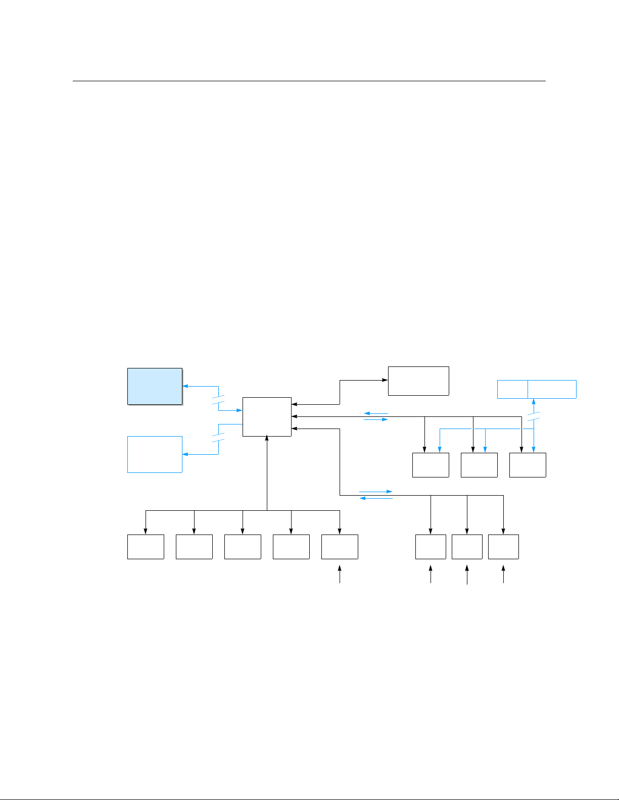
Introduction
Master Control
Subsystem
System
Controller
NV9000-SE
Utilities
Router
UniConfig
Router Router
• • •
GUI/
Status
• • •
Control
Status
SNMP
Auto-
mation
TallyUMD
Facility
Network
Ethernet
(operators)
(DHCP)
(operators)
Control
Panel
Status
Command
Control
Panel
Control
Panel
MRC
Router Config. Software
NV9000
Web Suite
Summary
• Configures and identifies, in detail, the many signal connections to and from routers.
Note that NV9000-SE Utilities does not exactly configure routers. For router configuration, there
are 3 main configuration programs:
• MRC. This program configures NV8500 hybrid routers (only).
• Uniconfig. This program configures all other NVISION series routers, such as the NV7512,
including NV8500 standard routers (those with EM0666 control cards).
• CRSC. This program configures compact routers.
The system controller receives commands from control panels, issues switching commands to
routers based on those commands, and returns status to the control panels.
If the tieline option is enabled, the system controller also performs tieline management. A
system controller can also perform certain other services.
Administrators can use NV9000-SE Utilities to view router status and tieline status, and to
perform certain system management tasks.
The NV9000 system provides sources that can be used and manipulated by master control
subsystems (which include iMC master control panels).
The NV9000 Web Suite (a browser application viewing DHP, tieline, and crosspoint data) can be
used to view system status remotely.
This is a schematic representation of an NV9000 system:
2
Control panels include
• Physical panels (such as the NV901, NV9640, or NV9649).
• CR series panels (such as the CP1604 or CP3232).
• Virtual panels (such as the NV9601V or NV9640V).
Virtual panels are software applications that emulate hardware panels and run on PCs on the
facility network.
• Software panels, or GUIs (such as the EC9700 and EC9710).
Page 21

NV9000-SE Utilities
User’s Guide
Routers include
• NVISION series routers such as the NV8576, NV5128, or NV7512.
• NVISION series compact routers (for instance, the CR1616-HD).
• Third-party routers that are compatible with NV9000 software.
A system controller can communicate with third-party router control systems such as the (GVG)
SMS7000 or (Probel) Cougar.
In the case of the SMS7000, the system controller runs an SMS7000 service to communicate
with the SMS7000. (The service must be enabled with a license key.)
A system controller can also control other system controllers.
Some router control systems can include an NV5100MC master control subsystem.
the master control subsystem is configured using specific master control configuration software
and not in NV9000-SE Utilities. It is in NV9000-SE Utilities, however, that the router ports used by
the master control subsystem are specified.
NVISION series routers are generally controlled over Ethernet (TCP/IP). However, they can be
controlled serially. Many third-party routers require serial control. The system controller can
control routers either way. Compact routers are UDP and are controlled over Ethernet only.
The NV960 system controller can have up to 32 serial ports per NIC. The typical NV960 system
controller has two NICs for Ethernet ports and one for serial ports. The NV920 has one serial port.
To be able to use NV9000-SE Utilities, you need familiarity with the concepts native to NVISION
series routers, control panels, and NV9000 router control systems. Panel operators should also
become familar with these concepts. The concepts are not difficult, but they might not be the
same as in the control system architecture from other vendors. Some configuration concepts are
suitable for some customers and unsuitable for other customers. Much depends on what your
requirements are.
2
In general,
Usage
You proceed with NV9000-SE Utilities either by creating a configuration or by opening an
existing configuration and writing the configuration to a system controller. You can also read a
configuration from a system controller, change it, and write the configuration back to the
system controllera, or to another system controller.
NV9000-SE Utilities usage occurs in roughly 4 phases:
1 Establish the identities of the system controllers in your system. This information persists
across configurations and sessions using NV9000-SE Utilities.
2 Access and modify a configuration.
You can do this by (a) creating a new, empty configuration, (b) opening an existing configuration, or (c) reading a configuration from a system controller.
You can define many different configurations. You can use whichever configuration you find
best suited to the different parts of your system.
3 Write configuration(s) to selected system controller(s).
4 Manage and validate system components and settings.
2. The NV5100MC is now obsolete. Support is still available, but units are no longer shipped. Now available are master control systems involving several Imagestore processors and iMC control panels.
3
Page 22

Introduction
User Interface Basics
Modifying a configuration is the most involved and complex task. In any configuration, you will:
• Identify and characterize the routers to be controlled. Routers will have already been config-
ured in MRC or UniConfig (or possibly CRSC). Routers are identified by the IP addresses of
their control cards. Routers generally have two redundant control cards, one active and one
standby.
Each IP address must be unique on its network.
Routers may also be connected serially, in which case, the port and protocol are specified,
not the IP address.
• Identify and configure the control panels in the system. It is in NV9000-SE Utilities that con-
trol panels are configured. Control panels are identified by panel ID. Their IP addresses are
determined by DHCP.
Panels may share configurations. Each panel’s ID must be unique.
You must identify and configure all panels that are to be used. That includes hardware panels, virtual panels, and any instances of the two software panels (EC9700 and EC9710).
• Define signal connections. Doing this involves defining levels, level sets, devices, and device
categories. These terms will be defined later.
• (Optionally) define tielines. This involves specifying which router ports are connected on the
tieline. The tielines thus defined form the pool of tielines the system controller uses during
operation. (Tieline design is not trivial.)
User Interface Basics
Important note: A system configuration is a data base. Changes made to the data base are
immediate without the possibility of an undo. However, many of the operations that modify
the data base include a ‘Commit’ button or ‘Save’ button so that you can perform the operations in relative safety. If you choose not to press the ‘Save’ button, operations that you
perform are discarded. After you press the ‘Save’ button
changes cannot be easily undone.
A technique that can help you as you work is to save successive copies of your configuration
as you develop it. If, in a later copy of your configuration, you make a terrible mistake
that would require much time spent in its correction
saved version of the configuration.
Launching NV9000-SE Utilities
There are 3 basic ways to launch NV9000-SE Utilities.
1 Double-click the desktop shortcut for NV9000-SE Utilities.
2 Choose Programs > NVISION > NV9000-SE Utilities from the Windows Start menu.
3 Double-click the executable file directly. Its default pathname is
C:\Program Files\NVISION\NV9000-SE Utilities\NV9000-SE Utilities.exe
In your installation, the pathname might differ.
(See also Installation
— committing your changes — the
— one
— you can simply revert to a previously
on page 29.)
4
Page 23
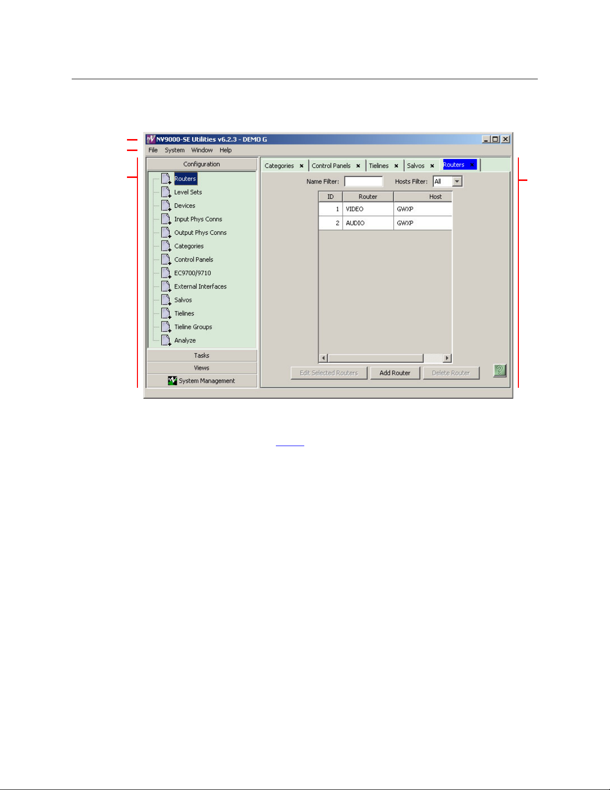
NV9000-SE Utilities
Navigation
Area
Tab be d
Work
Area
Title Bar
Menu Bar
Layout
After you launch NV9000-SE Utilities, you will see that its window has several sections:
User’s Guide
The title bar shows the revision number of NV9000-SE Utilities and the name of the configuration that you are viewing or editing.
The menu bar has 4 menus. See Menus
on page 11.
The work area can contain many tabbed work “pages.” Click on the tab of one of the open pages
to bring it to the foreground. You can click the “×” of a tab to close that page.
The navigation area consists of 4 panes:
• Configuration
• Tas ks
• Views
• System Management.
Click on the title of one of the panes and it expands open and the other panes collapse shut. The
entries in each of the panes represent work pages. Click on the entry in the pane to open the
work page. For example, click ‘Routers’ in the Configuration pane to open the routers page (as
shown in the illustration above).
Many work pages have buttons arrayed at the bottom of the page that open other work pages.
For example, in the illustration above, the routers page has an ‘Add Router’ button that opens a
page in which you can start the definition a router to be added to the configuration.
5
Page 24
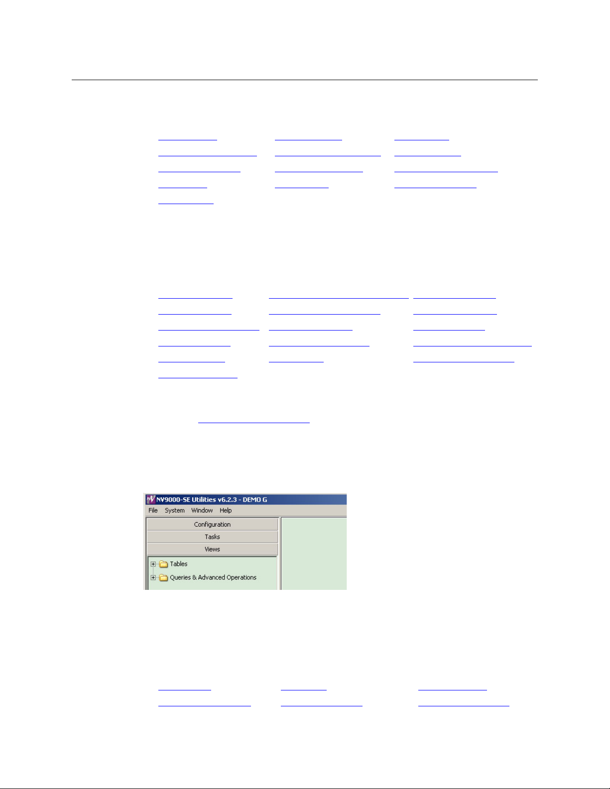
Introduction
User Interface Basics
Configuration Pane
The configuration pane provides these basic configuration pages:
‘Routers’
‘Input Phys Conns’ Page
Control Panels Page
Salvos Page
Analyze Page
Clicking any entry in the configuration pane makes the corresponding page available, and
visible, in the work area.
page ‘Level Sets’ Page Devices Page
‘Output Phys Conns’ Page Categories Page
EC9700/EC9710 Page ‘External Interfaces’ page
Tielines Page Tieline Groups Page
Tasks Pane
The tasks pane provides these slightly more complex configuration pages:
‘Add Router’
‘Add Device’ Page
‘Add Control Panel’ Page
‘Add Tieline’ Page
Import Data File
‘Find Routers’
Clicking any entry in the tasks pane makes the corresponding page available, and visible, in the
work area.
Of these, the ‘Add Mutiple Devices’ Page
page ‘Add Nvision Master Control’ Page ‘Add Level Set’ Page
‘Add Mutiple Devices’ Page ‘Add Category’ Page
‘Add SW Panel’ Page ‘Add Salvos’ Page
‘Add Tieline Group’ Page ‘Add External Interface’ page
Export to File ‘View Router Ports’ page
page
page is a considerable time-saver.
Views Pane
The views pane provides access to more detailed views of configuration data. The pane has two
sub-branches, ‘Tables’ and ‘Queries & Advanced Operations’:
This illustration shows the two branches collapsed. To expand a branch, click the “+” next to the
folder icon. If the branch is expanded, the icon will have changed to a “–” and clicking the “–”
will collapse the branch again.
Tabl es
The ‘Tables’ branch contains these entries:
Aliases Table
Category Details Table Control Points table Control Systems Table
Apps Table Categories Table
6
Page 25
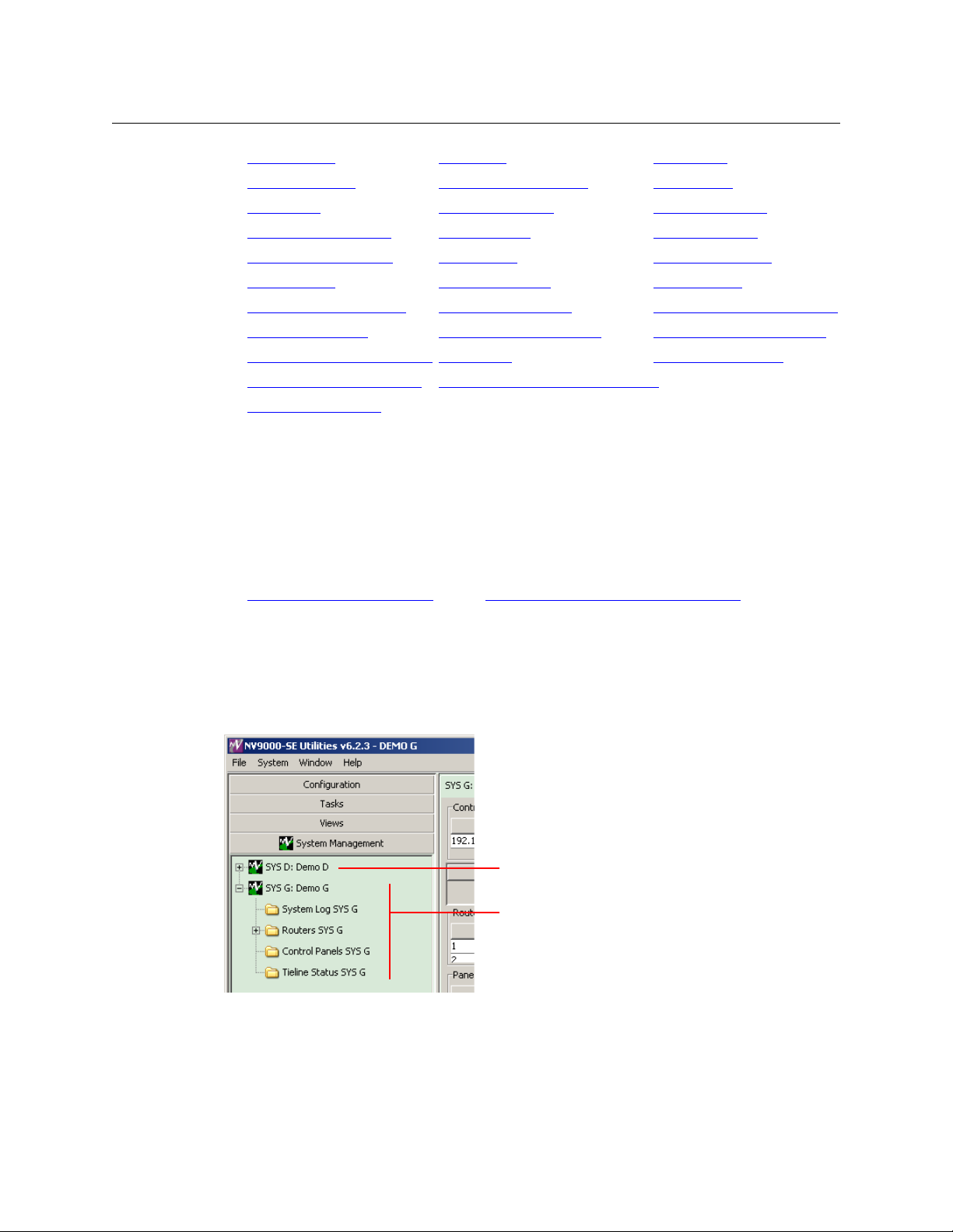
NV9000-SE Utilities
Expanded system controller entry
Collapsed system controller entry
User’s Guide
Devices Table GUIs Table Hosts Table
‘Level Sets’ Table
Paths Table
‘Router Controls’
Salvo List Details Table
Suffixes Table
Tieline2 Exclusions Table
Tieline2 Path Table
Tieline2 Signal Binding Table
‘Virtual Level Groups’ Table
‘XptExclusions’ Table
Note that Xpt (in XptExclusions) means “crosspoint.”
Note that the “2” in “Tieline2” means exactly nothing. It is present because of an artifact of the
database manager.
Clicking any entry in the list of tables brings the corresponding page to the work area.
table ‘Routers’ table Salvo Lists Table
‘Level Set Details’ Table Panels Table
‘PhysConns’ Table ‘PhysLevels’ Table
Salvos Table ‘Signal Type’ Table
‘SysParams’ Table Tieline2 Table
Tieline2 Group Table Tieline2 Group Binding Table
Tieline2 Path Detail Table Tieline2 Port Binding Table
Users Table ‘Virtual Levels’ Table
‘Virtual Level Signal Binding’ Table
Queries and Advanced Operations
The ‘Queries & Advanced Operations’ branch contains 2 entries:
‘Physical Connections’ Query
Clicking either of these entries brings the corresponding page to the work area.
‘Orphaned Physical Connections’ Query
System Management Pane
The system management pane does not provide access to configuration data, but lists the
system controllers in your system that you have identified:
Fig. 1-1: Identified System Controllers
You can select any system controller in this pane to review its status, to start or stop the system
controller, or to perform maintenance tasks.
Figure 1-1 shows two system controllers ‘SYS D’ and ‘SYS G’. Next to the name of each system
controller, separated by a colon (:) ,is the name of the configuration it uses.
7
Page 26
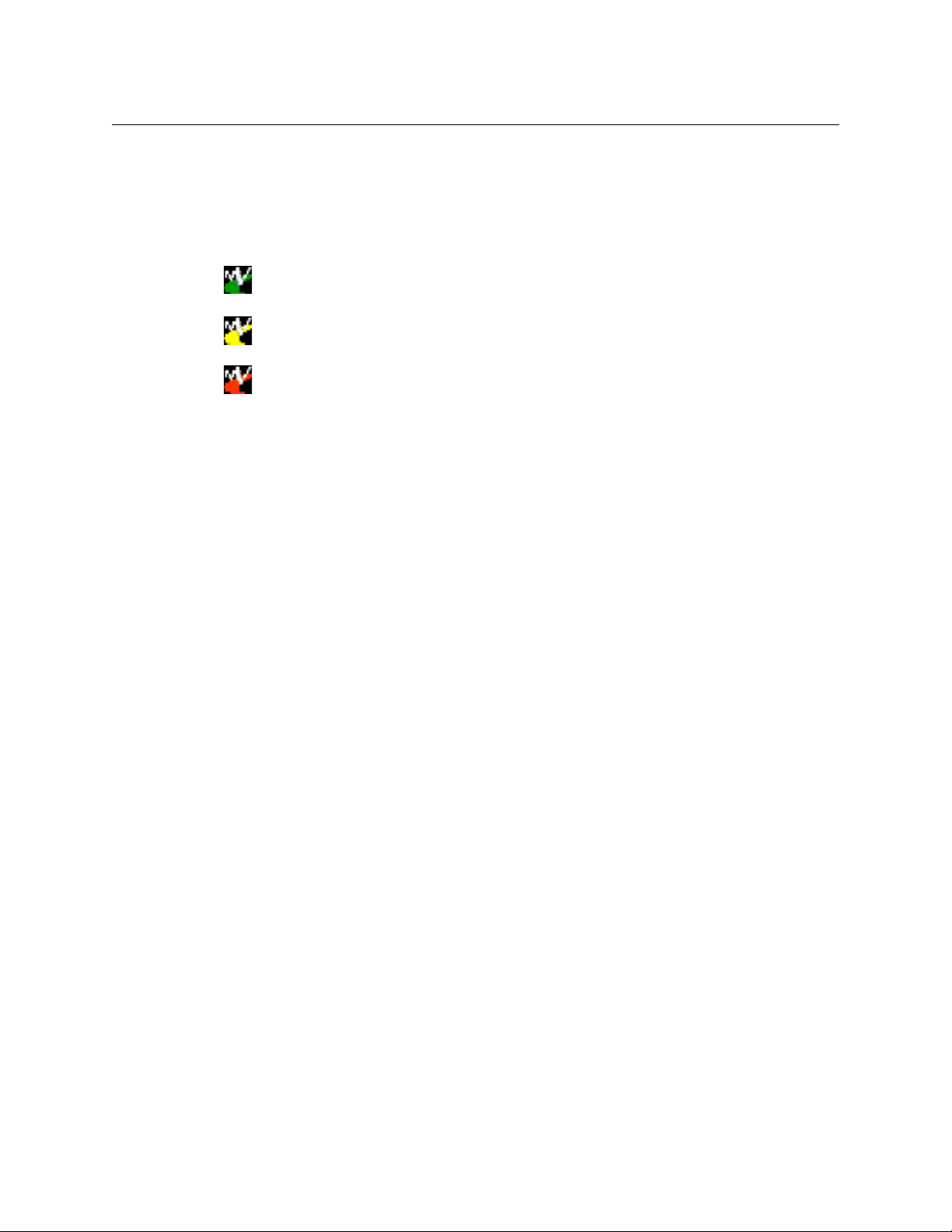
Introduction
User Interface Basics
Figure 1-1 shows SYS G expanded, revealing several folder icons: ‘System Log’, ‘Routers’, ‘Control
Panels’, and ‘Tieline Status’. Figure 1-1 shows that SYS D is not expanded. To expand the view of a
system controller, click the “+” next to the system controller’s icon. To collapse the view of a
system controller, click the “–” next to its icon.
The color of a system controller’s icon gives a rough indication of its state:
Green: the controller is connected (to your PC) and healthy.
Yellow: the controller is connected (to your PC) but is not healthy. Nevertheless, it is
capable of responding to NV9000-SE Utilities on your PC).
Red: the controller is not connected to your PC or is not functioning.
Clicking any entry in the system management pane causes a status and control page to appear
in the work area:
• Click a system controller to view a page in which you can start, stop, or restart a system con-
troller.
• Clicking a ‘System Log’ folder causes the system log page for the applicable system controller
to appear.
• Clicking a ‘Control Panels’ folder causes a control panels page for the applicable system con-
troller to appear.
• Clicking a ‘Tieline Status’ folder causes a tieline status page for the applicable system control-
ler to appear. This is a graphical representation of tielines defined in your configuration. The
diagram indicates the number of tielines between router (partitions) and the number of
tielines actually in use. A table of tieline usage data accompanies the diagram.
The ‘Routers’ entry is slightly different: it is an expandable icon. Click the “+” to expand the entry
or click the “–” to collapse the entry. When it is expanded, the entry lists the routers named in
the system controller’s configuration. See Figure 1-2, following.
8
Page 27
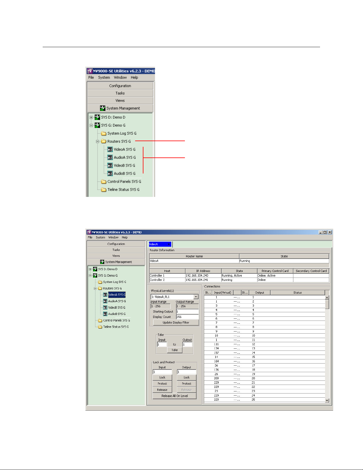
Click any router sub-entry to view the router page for that router:
Expanded ‘Routers’ folder
Defined routers
NV9000-SE Utilities
User’s Guide
Fig. 1-2: Expanded Router Section
Each router page includes a representation of the router’s crosspoints and tools with which you
can perform takes or locks or unlocks with respect to that router:
9
Page 28
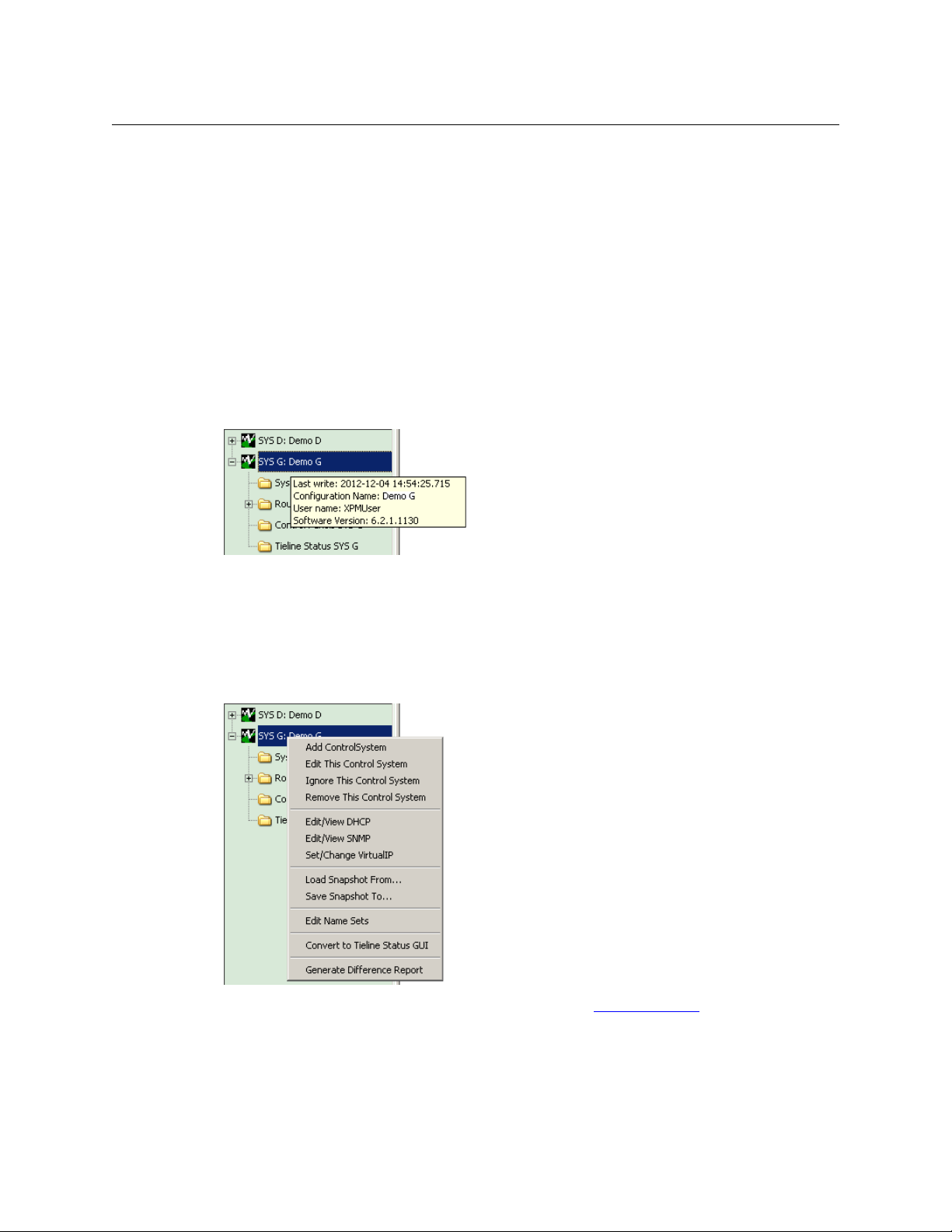
Introduction
User Interface Basics
The system management pane and the working pages it references are independent of configurations. The information contained in the system management pages is determined by (1) the
routers and control panels in your system, (2) the system controllers you have identified, and (3)
the state of the routers and control panels in your system.
It is through the system management pages that you can control the operation of the system
controllers and perform major and minor maintenance tasks on your system. That is, it is
through the system management pages that you can (1) upload and download configurations
to system controllers, (2) apply certain changes dynamically, (3) start, stop, and restart system
controllers, and (4) set and clear locks, and change router crosspoint states.
Hovering
If you hover your cursor over a system controller in the system management pane, an information message pops up briefly:
This message tells you the name of the system controller’s configuration, the date on which it
was configured, and the software version of the system controller.
Context Menu
If you right-click any system controller in the system management pane, a context menu
appears allowing you to configure additional aspects of the system controller:
The commands of the context menu are discussed under Navigation Pane
on page 88.
10
Page 29
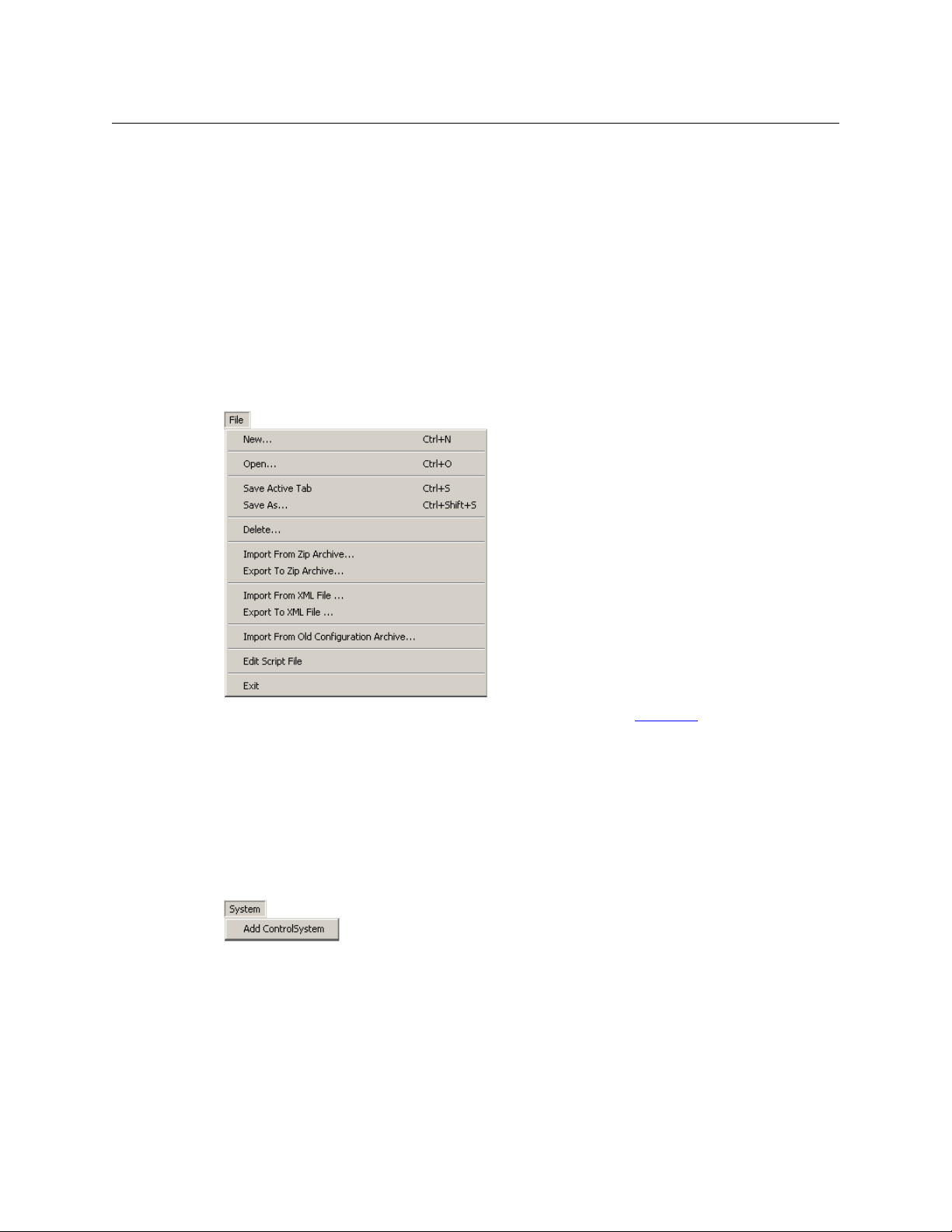
Menus
NV9000-SE Utilities
User’s Guide
NV9000-SE Utilities has 4 very simple menus:
• File
• System
• Window
• Help
Of these, the ‘File’ menu is the largest.
File Menu
The ‘File’ menu has several commands:
You can find more detail about the File menu commands under F
Most of the commands relate to opening or saving a configuration, either in the database repository on your PC or opening or saving an external file.
The ‘File’ menu also has an ‘Exit’ command. The ‘Exit’ commands terminates an NV9000-SE Utilities session.
ile Menu on page 19.
System Menu
The ‘System’ menu has one command:
The ‘Add Control System’ command adds a system controller (or a redundant pair of system
controllers) to NV9000-SE Utilities’s System Management page. After you add the system
controller, the System Management page can communicate with the actual system controller.
11
Page 30
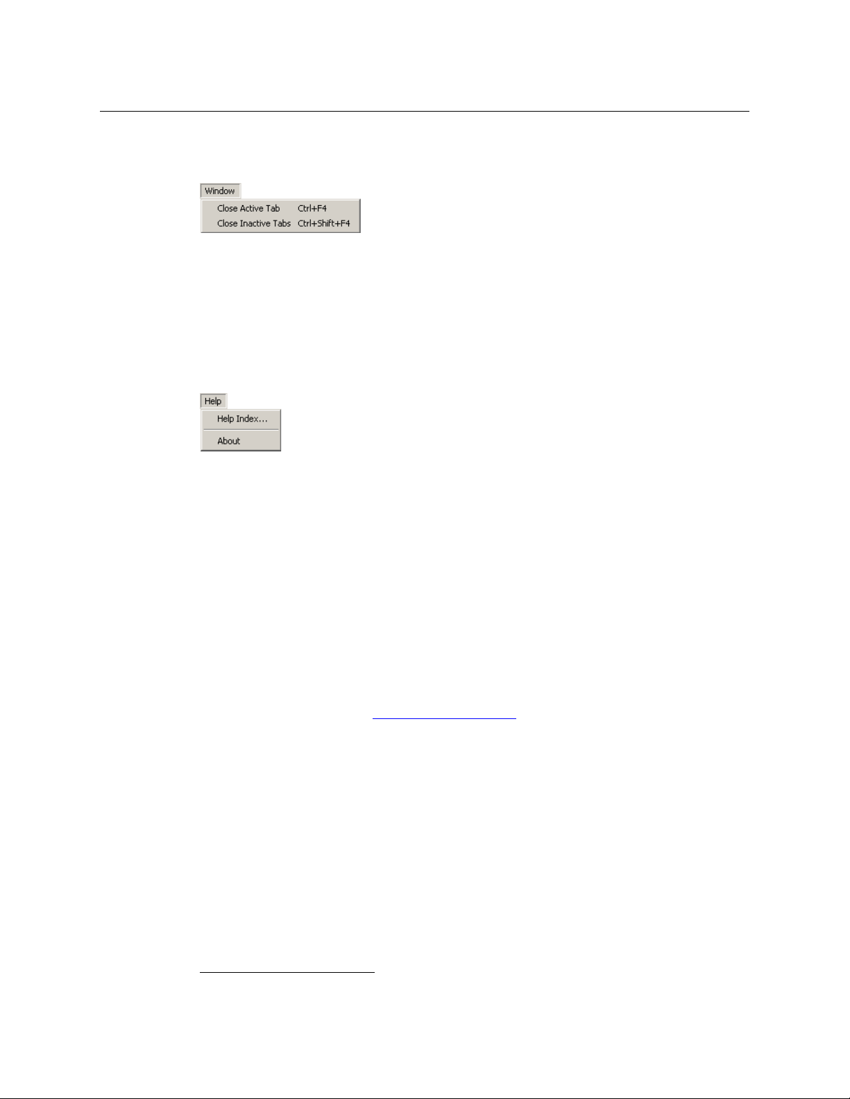
Introduction
Using Tables
Window Menu
The ‘Window’ menu has two commands:
The ‘Close Active Tab’ command closes one tabbed page: the page that is currently displayed,
i.e., the one that is in front of all other tabbed pages.
The ‘Close Inactive Tabs’ command closes all tabbed pages except the one that is active, i.e., it
does not close the one that is in front of all other tabbed pages.
Help Menu
The ‘Help’ menu has two commands:
The ‘Help Index . . .’ command causes NV9000-SE Utilities’ on-line help information to appear.
You can search the help information or browse through it. The content of the on-line help is
largely the same information as this PDF manual.
The ‘About’ command provides the current software revision of NV9000-SE Utilities.
Using Tables
Most configuration pages present data in tables. Each table row represents one record in the
configuration data base. All records in the data base have an identification number.
not all
column of the table. A notable exception is the control panels table, where the first column
represents the panel ID and not the data base record ID.
Note that It is possible to import data to, and export data from, certain tables, mainly the input
and output device tables. See Importing and Exporting
3
Most — but
— of the tables in NV9000-SE Utilities show the record identification number in the first
on page 453.
12
3. These are SQL IDs.
Page 31

This is an example:
Filters
A Row
A Cell
A Column
Page Title
Field Names
A Record ID
Buttons
NV9000-SE Utilities
User’s Guide
The table columns, of course, show the fields of the records represented on the table rows. The
column titles are the field names.
Below the table, you will find one or more buttons with which to manipulate the table and its
entries. In this illustration showing the ‘Devices’ page, the buttons are
• Edit Selected Devices.
• Add Device
• Delete Device.
The buttons for other configuration pages will be different.
You can select one or more rows in the table using standard techniques. Click a row to select a
row. Click a row, then shift-click another row to select multiple contiguous rows. Control-click
multiple rows to create a disjoint (or non-contiguous) selection.
In the ‘Devlces’ page, if you select one or more rows, and then click ‘Edit Selected Devices’,
NV9000-SE Utilities opens a configuration page for each device that you have selected.
If you select one or more rows, and then click ‘Delete Device’, NV9000-SE Utilities deletes each
device that you have selected. (NV9000-SE Utilities will present a confirmation alert message
before it deletes the rows).
If you click ‘Add Device’, NV9000-SE Utilities opens an ‘Add Device’ page in which you can specify
a new device.
The many configuration pages in NV9000-SE Utilities contain different data, but all of their data
tables function in much the same way.
13
Page 32

Introduction
Using Tables
Table Ordering
Tables can be adjusted to make viewing information easier. You can:
• Adjust the position and width of the table columns by sliding the column dividers between
the column headers.
• Sort the table based on the data in a specific column by clicking the column header. Clicking
once gives an ascending order; clicking again gives a descending order.
The initial view of a table follows NV9000-SE Utilities’ default ordering.
Entering Data
Data are entered in table cells which correspond to data base fields. Fields can be “free text” in
which you type in the data or fields can have drop-down lists from which you choose an entry.
Clicking in a field either activates it for text entry or activates the field’s drop-down list.
Filters
Many configuration pages have fill-in text areas or drop-down lists located at the top of the
window. These are called filters. Filters let you reduce the number of items listed to only those
that contain the text you entered in the filter(s). For example, if you enter “99” as a filter for a list
of devices, only those devices that contain “99” in their name are displayed.
Many tables have a level set filter. Choose a level set in the drop-down list for these filters to
restrict the table to those items that correspond to devices in the level set.
Table Shor tcuts
These following key strokes, or shortcuts, help you position the focus of your activity on a particular table cell. That is, these shortcuts help you select a table cell:
• Tab and shift-tab
Pressing tab, on your keyboard, advances through the cells of a table in the page, one cell at
a time. If you press tab when the focus is at the end of a row, NV9000-SE Utilities moves the
highlight to the next row and the focus to the first entry in that row.
Pressing shift-tab advances through the cells of a table, but in reverse order.
(Tabbing through a table does not help you unless you move the “focus” to a cell that is editable.)
• Up and down arrow keys
These arrow keys move the “focus” up or down through the rows of a configuration table.
The up and down arrows primarily select the next, or previous, row.
• Left and right arrow keys
These arrow keys move the “focus” left or right through the fields of a table row
advancing to another row.
(Moving within a row does not help you unless you move the “focus” to a cell that is editable.)
— without
14
Page 33

NV9000-SE Utilities
User’s Guide
Which table cell is selected might be hard to see, especially if the table row is highlighted.
The selected cell is indicated
(1) by a thin dotted line around the cell (in which case, the cell is not editable):
(2) by the cell changing to an editing format:
or (3) by the cell changing to a drop-down list:
Shortcuts
• Single-clicking
Single-click a table cell to edit the data in the cell.
• Double-clicking
Double-click a table cell (that is not editable) to access the configuration page for the data
represented by the row that contains the cell.
NV9000-SE Utilities has several shortcut commands. All shortcuts are performed using keys on
your keyboard.
Double-Click Option
To select and open any item in any page listed in the ‘Configuration’ pane, simply double-click
on it. A page opens displaying details for that item.
File Menu
The following keyboard shortcuts relate to the ‘File’ menu:
• Ctrl+N — Creates a new configuration.
• Ctrl+O — Opens an existing configuration.
• Ctrl+S — Saves the current configuration.
• Ctrl+Shift+S — A “save as” command that saves the current configuration under a new
name.
The ‘File’ menu lists the shortcuts next to the commands to which they apply.
15
Page 34

Introduction
Shortcuts
When Configuring a Control Panel
These shortcuts are available when you are using NV9000-SE Utilities to configure a control
panel:
• ‘D’ or ‘d’ — Makes the currently selected button a destination button. If the last button you
selected was also a destination button, the new destination button is assigned the next destination in the list of destinations.
• ‘S’ or ‘s’ — Makes the currently selected button a source button. If the last button you
selected was also a source button, the new source button is assigned the next source in the
list of sources.
• ‘L’ or ‘l’ — Makes the currently selected button a level button. If the last button you selected
was also a level button, the new level button is assigned the next (virtual) level in the list of
levels.
• ‘C’ or ‘c’ — Makes the currently selected button a category button. If the last button you
selected was also a category button, the new category button is assigned the next category
in the list of categories.
• ‘U’ or ‘u’ — Makes the currently selected button “undefined.”
• ‘Delete’ key— The same as pressing ‘U’ or ‘u’.
• ‘T’ or ‘t — Changes the panel selection focus to the ‘Button Type’ drop-down list. Same as
clicking in the ‘Button Type’ field of the panel configuration page.
When you are choosing an entry in the ‘Button Type’ field, you can press letter keys repeatedly to browse the the lists of button types that start with that letter. For instance, pressing
“S” repeatedly would cause the button type selection to become “Salvo,” “Save Preset,”
“Selection,” “Source,” “Source Master,”and “Source/Destination” in succession.
Note that such changes in button type occur in the context of the ‘Button Type’ field.
Pressing “S” (or any other letter) when you are not in the button type field has a different
result, as noted above.
• ‘1’, ‘2’, ‘3’ or ‘4’ — Places the focus in the first, second, third or fourth (as applicable) drop-
down list after the ‘Button Type’ field.
For these keys to work, you must have just previously selected a button proxy in the
panel graphic.
• ‘Alt’ + ‘b’ — Moves the configuration page focus to the image (or proxy) of the button being
configured.
• ‘Alt’ + ‘Shift’ + ‘b’ — Same as ‘Alt’ + ‘b’.
• ‘Tab’ — If a button is selected, pressing tab moves the focus to the next button (in the button
ordering). If a check box, text field, or drop-down box is selected, the focus is advanced to
the next check box, text field, or drop-down box, in cyclical rotation.
• ‘Shift’ + ‘Tab’ — If a button is selected, the focus is moved to the previous button. If a check
box, text field, or drop-down box is selected, focus is reverted to the previous check box, text
field, or drop-down box in cyclical rotation.
16
Page 35

What to Do and When to Do It
NV9000-SE Utilities is an integral part of getting your system controller up and running effectively and efficiently. Before using NV9000-SE Utilities, determine how data is going to be
managed in your facility and decide what inputs and outputs can be grouped together. Inputs
and outputs can be grouped together if they have a common attribute, such as a signal type,
facility room, and so on. In general, signal type is the best grouping to use. Figuring this out from
the start will make configuration easier, faster and help minimize having to make changes in the
future.
Before using NV9000-SE Utilities, all routers should be configured using MRC or UniConfig
configuration software for Grass Valley routers, or for third-party routers, configured according
to the manufacturer’s directions.
The levels entered for the routers (for Grass Valley routers, the levels are entered in MRC or
UniConfig) will later be matched to the physical levels entered in NV9000-SE Utilities.
NV9000-SE Utilities saves all initial configurations and configuration changes to the database.
Once changes are saved, there is no “undo” function; the configuration is permanently altered.
To implement configuration changes, the NV9000 system controller must write the configuration and then be restarted.
NV9000-SE Utilities
User’s Guide
Configuration Steps
All changes can be made offline and later implemented, or changes may also be made dynamically if NV9000-SE Utilities is currently connected to the system controller.
1 If necessary, add system controllers to NV9000-SE Utilities.
2 Add routers to NV9000-SE Utilities.
Routers are added by entering the physical levels (partitions) to NV9000-SE Utilities. At this
time, virtual levels can be mapped to physical levels. Virtual levels are abstractions that can
be applied to any device or router and allow for inter-device communication.
3 Create level sets in NV9000-SE Utilities.
4 Add devices to NV9000-SE Utilities.
Describe each device connected to the routers: what devices are sending a signal to the
router and what devices are receiving signals from the router. Devices can only be added
after level sets have been created. When added, each device should be assigned to a level
set. The level sets should reflect the signals used by the device. NV9000-SE Utilities has no
way of determining what signal type is being used by a device without assigning it a virtual
level within a level set.
Device information may also be imported from a spreadsheet.
5 Group devices by category in NV9000-SE Utilities.
Organize devices into categories. Categories are groupings of devices with common
attributes, such as device type (e.g., monitor), or location (e.g., studio A), or use (e.g., editing).
Category labels display on control panels for operators, making selection quick and easy.
A category can only be added after devices have been added to NV9000-SE Utilities. Not all
devices must be added, but adding as many devices as possible before creating categories
ensures that the categories accurately define the devices in your facility.
Category information may also be imported from a spreadsheet.
17
Page 36

Introduction
What to Do and When to Do It
6 Add control panels to NV9000-SE Utilities.
Control panels, both hardware and software, are configured using NV9000-SE Utilities. Configuration control panel interfaces is relatively easy because NV9000-SE Utilities mimics the
control panel layout and displays what the operator will see on the screen or panel.
7 Add or manage additional features in NV9000-SE:
Depending on your facility needs, you can also:
• Create salvos.
• Create tielines.
• Update hosts.
• Add Master Control.
• Manage users.
18
Page 37

Summary
Menus
Chapter 2 describes the NV9000-SE Utilities menus.
Topics
Summary . . . . . . . . . . . . . . . . . . . . . . . . . . . . . . . . . . . . . . . . . . . . . . . . . . . . . . . . . . . . . . . . . . . . . . . . . . . . . . . . 19
File Menu . . . . . . . . . . . . . . . . . . . . . . . . . . . . . . . . . . . . . . . . . . . . . . . . . . . . . . . . . . . . . . . . . . . . . . . . . . . . . . . . . 19
System Menu . . . . . . . . . . . . . . . . . . . . . . . . . . . . . . . . . . . . . . . . . . . . . . . . . . . . . . . . . . . . . . . . . . . . . . . . . . . . . 26
Window Menu . . . . . . . . . . . . . . . . . . . . . . . . . . . . . . . . . . . . . . . . . . . . . . . . . . . . . . . . . . . . . . . . . . . . . . . . . . . . 27
Help Menu . . . . . . . . . . . . . . . . . . . . . . . . . . . . . . . . . . . . . . . . . . . . . . . . . . . . . . . . . . . . . . . . . . . . . . . . . . . . . . . 28
NV9000-SE Utilities has 4 menus:
• File
• System
• Window
• Help
Of these, the ‘File’ menu is the largest.
File Menu
The ‘File’ menu primarily accesses configuration files. It has 12 comands:
19
Page 38

Menus
File Menu
These are the commands:
• New
The ‘New’ command creates a new configuration. When you click ‘New’ — or type Ctrl-N —
NV9000-SE Utilities presents a dialog in which you can specify the new configuration’s name:
Enter the new configuration name and click ‘OK’ to create the new configuration. Click ‘Cancel’ otherwise.
If a configuration by the name you give already exists, NV9000-SE Utilities presents a confirmation dialog to protect you from overwriting existing data:
Click ‘Yes’ to continue, ‘No’ to return to the dialog to enter another name, and ‘Cancel’ to
abort the ‘New’ command.
(The configuration created is stored
C:\Users\‹user›\CtrlSysConfigs.)
— in a subfolder — in the folder
• Open
The ‘Open’ command opens an existing configuration. When you click ‘Open’ — or type CtrlO — NV9000-SE Utilities presents a list of existing configurations from which you may
choose one to open:
The configurations listed are those named
C:\Users\‹user›\CtrlSysConfigs. It is possible to move configurations (subfolders) in
and out of
CtrlSysConfigs. A configuration subfolder must have been created in NV9000-
— as subfolders — in the folder
SE Utilities, otherwise NV9000-SE Utilities cannot open the configuration.
• Save Active Tab
The ‘Save Active Tab’ command commits changes you have made in the active configuration
(if that page that has a ‘Save’ button). Its function is exactly the same as the ‘Save’ button’s
20
Page 39

NV9000-SE Utilities
User’s Guide
function. The keyboard shortcut for this command, Ctrl-S, is a convenient way to save
changes quickly and frequently.
• ‘Save As . . .’
The ‘Save As . . .’ command saves the configuration you are editing under another name.
When you click ‘Save As . . .’ — or type Ctrl-Shift-S — NV9000-SE Utilities presents a dialog in
which you can specify the new configuration’s name:
If a configuration by the name you give already exists, NV9000-SE Utilities presents a confirmation dialog to protect you from overwriting existing data:
Click ‘Yes’ to continue, ‘No’ to return to the dialog to enter another name, and ‘Cancel’ to
abort the ‘New’ command.
(The configuration saved is stored
C:\Users\‹user›\CtrlSysConfigs.)
— in a subfolder — in the folder
• ‘Delete . . .’
The ‘Delete . . .’ command deletes the configuration you are editing. When you click
‘Delete . . .’, NV9000-SE Utilities presents a confirmation dialog:
Click ‘Yes’ to delete the configuration or ‘No’ to cancel the deletion.
21
Page 40

Menus
File Menu
After you delete the configuration, NV9000-SE Utilities has no configuration open. and the
‘File’ menu has a reduced set of commands:
• ‘Import from Zip Archive . . .’
The ‘Import from Zip Archive . . .’ command opens a configuration that was previously
exported as a .zip file, perhaps remotely. When you click ‘Import from Zip Archive . . .’,
NV9000-SE Utilities presents an ‘Open’ dialog:
22
Browse to locate the .zip file in which you are interested. Select the file and click ‘Open’ to
open the .zip file or click ‘Cancel’ to stop the operation.
Page 41

NV9000-SE Utilities
User’s Guide
• ‘Export to Zip Archive . . .’
The ‘Export to Zip Archive . . .’ command saves your configuration in a .zip file. The .zip file
can be opened later, perhaps at another workstation. When you click ‘Export to Zip
Archive . . .’, NV9000-SE Utilities presents a ‘Save’ dialog:
Browse to locate the folder in which to save the .zip file. The default name for the file is the
configuration name (followed by .zip). You may enter any name you like. Click ‘Save’ to save
the .zip file or click ‘Cancel’ to stop the operation.
The .zip file you create this way may be opened with the ‘Import from Zip Archive . . .’ command in any instance of NV9000-SE Utilities anywhere (as long as the instance is at a recent
revision).
23
Page 42

Menus
File Menu
• ‘Import from XML File. . .’
The ‘Import from XML File . . .’ command opens a configuration that was previously exported
as an XML file, perhaps remotely. When you click ‘Import from XML File . . .’, NV9000-SE Utilities presents an ‘Open’ dialog:
Browse to locate the .xml file in which you are interested. Select the file and click ‘Open’ to
open the .xml file or click ‘Cancel’ to stop the operation.
• ‘Export to XML File. . .’
The ‘Export to XML File . . .’ command saves your configuration in a .xml file. The .xml file can
be opened later, perhaps at another workstation. When you click ‘Export to XML File . . .’,
NV9000-SE Utilities presents a ‘Save’ dialog:
24
Page 43

NV9000-SE Utilities
User’s Guide
Browse to locate the folder in which to save the .xml file. The default name for the file is the
configuration name (followed by .xml). You may enter any name you like. Click ‘Save’ to save
the .xml file or click ‘Cancel’ to stop the operation.
The .xml file you create this way may be opened with the ‘Import from XML File . . .’ command in any instance of NV9000-SE Utilities anywhere (as long as the instance is at a recent
revision).
• ‘Import from Old Configuration Archive . . .’
The ‘Import from Old Configuration Archive . . .’ command opens a configuration that was
previously exported in a very old configuration (prior to NV9000-SE Utilities v4.0). When you
click ‘Import from Old Configuration Archive . . .’, NV9000-SE Utilities presents an ‘Open’ dialog:
Browse to locate the archive in which you are interested. Select the file and click ‘Open’ to
open the archive or click ‘Cancel’ to stop the operation.
25
Page 44

Menus
System Menu
• Edit Script File
This command is only for Grass Valley service technicians. (If you click the command, a window
appears in which you can edit a script.)
If you are not a Grass Valley service technician, you may ignore this command (and its window).
• Exit
To leave and close NV9000-SE Utilities, click ‘Exit’.
System Menu
The ‘System’ menu has one command: ‘Add Control System’:
When you click ‘Add Control System’, NV9000-SE Utilities presents a dialog in which to identify
the control system.
Here, by “control system” is meant an NV9000 system controller, i.e, an NV960, NV920 or a
redundant pair of NV60s or NV920s.
26
Page 45

NV9000-SE Utilities
User’s Guide
This is the dialog:
Place a check in the ‘Redundant’ check box if your control system is a pair of system controllers.
Enter the name of the control system in the ‘Control System name’ field.
Enter the IP address of the first system controller in the first IP address field. If the control system
is redundant, also enter the IP address of the second system controller in the second field.
Click ‘Save and Dismiss’ to create an entry in the ‘System Management’ page and close the
dialog.
Click ‘Save and Clear’ to create an entry in the ‘System Management’ page and keep the dialog
open so that you can create another control system.
Click ‘Cancel’ to close the dialog without creating another control system entry in the ‘System
Management’ page.
The control system entries you create appear as icons in the left side of the ‘System Management’ page. The icons appear green when the actual control system is healthy, yellow when the
control system is partially healthy (and commounication with the control system can be established) and red when communication cannot be established.
Window Menu
The ‘Window’ menu has two commands that refer to the visible configuration pages (or tabs):
These are the commands:
• Close Active Tab
When you click ‘Close Active Tab’ — or Ctrl-F4 — NV9000-SE Utilities closes the active configuration page. The active page is the one that is in the foreground among the configuration pages that are displayed.
• Close Inactive Tabs
When you click ‘Close Inactive Tabs’
inactive configuration pages. The active page is the one that is in the foreground among the
configuration pages that are displayed. Inactive pages are all the other pages.
— or Ctrl-Shift-F4 — NV9000-SE Utilities closes all the
27
Page 46

Menus
Help Menu
Help Menu
The ‘Help’ menu has two commands:
These are the commands:
• ‘Help Index . . .’
When you click ‘Help Index . . .’, NV9000-SE Utilities opens the on-line help system.
• About
When you click ‘About’, NV9000-SE Utilities displays information about NV9000-SE Utilities
and its revision:
28
Page 47

Chapter 3 provides installation instructions.
NV9000-SE Utilities normally ships to you on a Grass Valley software and documentation CD
(part number SB0033-17). Use the CD’s autoplay menus to navigate to, and click the installation
button for, NV9000-SE Utilities.
If you have received the NV9000-SE Utilities installation program by some other means, simply
locate and double-click the installer file.
The installation process will then begin. It is simple and quick.
You may install NV9000-SE Utilities on as many PCs as you like.
NV9000-SE Utilities runs under Windows XP, Windows Vista, or Windows 7.
Take the following steps to install NV9000-SE Utilities.
From the CD
1 Place the SB0033-17 CD provided in the CD Rom drive of your PC. The CD should automati-
Installation
cally display its initial menu after a few seconds:
Click ‘Configuration Software’.
29
Page 48

Installation
Without the CD
2 In the window that appears next, click ‘Install NV9000-SE Utilities’:
The installer will launch and present several simple dialogs regarding your preferences for
the installation.
If the autoplay menu fails to appear (as it might on systems having strong security), open the
CD and navigate to
installer. It will be named
software revision.
3 Proceed to step 6, following, to complete the installation.
Without the CD
4 If you have received the NV9000-SE Utilities installation program from a Grass Valley service
technician, perhaps on a USB device, locate and double-click the installer file. This file will be
named
sion. The installation process will begin.
5 Proceed to step 6, following, to complete the installation.
‹cd drive›:\Software and double-click the NV9000-SE Utilities
SEUtilitiesV6.3.3 Installer.exe or similar, depending on its
SEUtilitiesV6.3.3 Installer.exe or similar, depending on its software revi-
30
Page 49

In Either Case
6 A few moments after you launch the installer, its first window appears:
7 Read the introductory information and click Next to proceed. The ‘Choose Install Folder’
screen appears:
NV9000-SE Utilities
User’s Guide
8Click Choose to browse to the folder you want.
At any time, you can click Restore Default Folder to choose the installer’s default folder. By
default, NV9000-SE Utilities is installed at:
Utilities\.
Finally, click Next.
C:\Program Files\Miranda\NV9000-SE
31
Page 50

Installation
In Either Case
9 Verify that the information on the ‘Pre-Installation Summary’ screen is correct, as shown:
To update the information that displays, click Previous to return to a previous screen, updating information as needed. When you are done, click Next on each screen until the ‘PreInstallation Summary’ screen appears.
Finally, click Install.
10 The ‘Installing . . .’ screen appears, showing installation progress:
32
Installation proceeds automatically.
Click Cancel if you want to cancel the installation.
Page 51

NV9000-SE Utilities
User’s Guide
11 When the installation is complete, the ‘Installation Complete’ screen appears:
Click the radio button to restart your computer either now or at a later time. Then click Done.
It is recommended that you restart your computer at this time. The installation window
closes.
When your computer restarts, NV9000-SE Utilities will be installed. Until you restart, NV9000SE Utilities will not function correctly.
33
Page 52

Installation
In Either Case
34
Page 53

Chapter 4 describes the ‘Routers’ configuration page.
Topics
Introduction to NVISION Series Routers . . . . . . . . . . . . . . . . . . . . . . . . . . . . . . . . . . . . . . . . . . . . . . . . . . . 35
Router Configuration
‘Routers’
‘Add Router’
Router Details Page
‘Routers’
‘Router Controls’
Control Points
‘View Router Ports’
‘Find Routers’
Virtual Crosspoints
NVISION Profiles
page . . . . . . . . . . . . . . . . . . . . . . . . . . . . . . . . . . . . . . . . . . . . . . . . . . . . . . . . . . . . . . . . . . . . . . . . . . . . 39
page . . . . . . . . . . . . . . . . . . . . . . . . . . . . . . . . . . . . . . . . . . . . . . . . . . . . . . . . . . . . . . . . . . . . . . . . . 40
table . . . . . . . . . . . . . . . . . . . . . . . . . . . . . . . . . . . . . . . . . . . . . . . . . . . . . . . . . . . . . . . . . . . . . . . . . . . . 50
in NV9000-SE Utilities . . . . . . . . . . . . . . . . . . . . . . . . . . . . . . . . . . . . . . . . . . . . . . . 38
. . . . . . . . . . . . . . . . . . . . . . . . . . . . . . . . . . . . . . . . . . . . . . . . . . . . . . . . . . . . . . . . . . . . . . . 45
table . . . . . . . . . . . . . . . . . . . . . . . . . . . . . . . . . . . . . . . . . . . . . . . . . . . . . . . . . . . . . . . . . . . . 51
table . . . . . . . . . . . . . . . . . . . . . . . . . . . . . . . . . . . . . . . . . . . . . . . . . . . . . . . . . . . . . . . . . . . . . . 55
page . . . . . . . . . . . . . . . . . . . . . . . . . . . . . . . . . . . . . . . . . . . . . . . . . . . . . . . . . . . . . . . . . . 58
page . . . . . . . . . . . . . . . . . . . . . . . . . . . . . . . . . . . . . . . . . . . . . . . . . . . . . . . . . . . . . . . . . . . . . . . 59
. . . . . . . . . . . . . . . . . . . . . . . . . . . . . . . . . . . . . . . . . . . . . . . . . . . . . . . . . . . . . . . . . . . . . . . 59
. . . . . . . . . . . . . . . . . . . . . . . . . . . . . . . . . . . . . . . . . . . . . . . . . . . . . . . . . . . . . . . . . . . . . . . . . . 63
Introduction to NVISION Series Routers
Routers
An NVISION series router is a device that has a certain number of inputs and outputs and internally connects inputs to (one or more) outputs, allowing signals to flow from the input to the
output. Inputs and outputs are connected to ports of video and audio devices of various kinds.
When an input is connected to an output, we say it is routed to the output. (We also say it is
taken to the output).
With the exception of machine control routers, all NVISION series routers are called “X-Y” routers
or standard routers. These routers have M inputs and N outputs that can be depicted as an X-Y
grid with inputs on one axis and outputs on the other. They employ one or more crosspoint
switches to perform the routing. The X-Y routers are non-blocking: any input can be routed to
any or all outputs.
In contrast, machine control routers use a point-to-point architecture, with exceptions. Ports are
bidirectional. One machine control port can be connected, as an input, to one other port, as an
output. The exceptions are when a machine control router is used as a “data router” in which
case it is considered an X-Y router and when the machine control router is in broadcast mode.
Large-Format Routers
Grass Valley’s NVISION series routers include:
NV8500 Series Includes the NV8140, NV8144, NV8280, NV8576, and NV8576-Plus.
These routers vary in size up to 1152
18,432 (audio). The NV8500 series supports 3Gig, HD, and SD, AES,
MADI, and IP.
× 1152 (video) and 18,432 ×
35
Page 54

Routers
Introduction to NVISION Series Routers
NV8256-Plus The NV8256-Plus is a 22RU video router that supports 3Gig, HD,
NV8288, NV8288-Plus The NV8288 is a 10RU video router (about 12” deep) that supports
NV7512, NV7512-Plus The NV7512 is a 14RU audio router that supports analog audio,
NV5256, NV5256-Plus The NV5256 is an 8RU machine control router connecting up to
NV5128-MFR The NV5128-MFR is a multi-format router (hence, MFR). It switches
There are other router models. Most of them are no longer in production.
The NV8500 family hybrid routers are configured in MRC. All other routers, including NV8500
family standard routers, are configured in UniConfig.
The inputs and outputs handled by routers are configurable in NV9000-SE Utilities, and the definition of I/O devices is properly a control system subject, not a router subject.
and SD, up to 512×512.
HD and SD, up to 288×576. The NV8288-Plus, in two frames, supports a 576×576 matrix.
AES and MADI. The NV7512 hsa a 512×512 matrix. The NV7512Plus is expandable to 2048 × 2048 (4096×4096 mono).
256 machine control ports. The NV5256-Plus, in two frames, supports 512 ports. The NV526 and NV5256-Plus can be used as data
(X-Y) routers also.
video (analog or digital), audio (analog or AES) and machine control signals. It is highly configurable and has a 128×128 crosspoint
matrix. The NV5128-MFR also supports (now discontinued) master
control modules and their functions.
Compact Routers
Grass Valley also has an extensive series of compact routers, ranging in size from 8×2 to 32×32,
and compact control panels. The CR series, as these routers are called, support analog and
digital video (including 3Gig, HD, and SD), analog and digital audio, and machine control.
Included in the CR series is a set of “clean and quiet” routers — the CQX routers — that can
perform video and audio fades during transitions.
All compact routers are configured in CRSC (Compact Router System Configurator).
Compact control panels, when configured, are usually configured in NV9000-SE Utilities.
Definitions
A router input or a router output is a single connector or a group of terminals that functions as a
single connector. (Inputs and outputs are collectively called ports.)
The devices connected to router inputs are called source devices. A source device (in NV9000-SE
Utilities) is a set of inputs (on one or more routers).
The devices connected to router outputs are called destination devices. A destination device (in
NV9000-SE Utilities) is a set of outputs (on one or more routers).
Some devices (such as VTRs) have both inputs and outputs. Thus, in NV9000-SE Utilities, a device
can be both a source and a destination (i.e, it comprises a set of input ports and output ports.)
36
Page 55

NV9000-SE Utilities
User’s Guide
Partitions
The crosspoint matrix of a router can be partitioned. Partitions can exist for several reasons. For
instance, some routers support more than one signal type. Thus partitioning is a way to allow
different signal types to coexist in one router.
A partition is usually called a physical level. This is in distinction from a virtual level which is
another NV9000-SE Utilities concept.
Principles of Partitions
1 A partition has a defined size and includes both inputs and outputs. It also has a defined par-
tition type. (See Partition Types
and and ending port number for inputs and the same for outputs.
2 Signals can be switched only within a partition, never directly from one partition to another.
3 A router crosspoint matrix must be configured as having at least one partition. It can be the
entire matrix.
If the entire matrix is a single partition, the matrix is not actually partitioned (i.e., divided
into parts). However, the configuration data base requires you to define at least one
partition.
4 Partitions may overlap. For example, if an NV8500 standard router has AES cards inter-
spersed with video cards, it is acceptable to define two partitions that overlap completely
one video and one AES — and that occupy the entire crosspoint matrix space.
5 Not every port in a partition need be used.
6 The NV8500 hybrid routers have two distinct matrices: one for video and one for audio. The
matrix for audio is not a crosspoint matrix; it is a TDM “matrix” that for convenience is treated
as a crosspoint matrix. It is generally necessary to define one partition for the video and
another for the audio.
7 As is evident with the NV8500 hybrid routers, not every port in a partition is available. Each
disembedder card, for instance, has 16 unused or unusable audio ports. These ports are
numbered in the partition, but do not have any corresponding circuitry.
8 It is possible to overlay router partitions to implement both a stereo model for switching
audio and a “mono” model.
9 Partitions are defined in MRC or UniConfig, which configure routers. The same partitions
must also be defined
— identically — in the router definitions in NV9000-SE Utilities.
Most NVISION series routers allow up to 4 partitions. The NV5128-MFR allows 8 partitions
because it supports many signal types.
, following.) The size is configured as a starting port number
—
Partition Types
These are the supported partition types, for NV8500 series routers:
Video Audio
Digital Video Asynchronous AES
Synchronous Audio
Synchronous Stereo Audio
For the NV8500 series, the term “synchronous audio” means audio that is switched according to
the timing of a video signal and a video reference. The term “asynchronous AES” refers to AES
signals that are independent of any video.
37
Page 56

Routers
Router Configuration in NV9000-SE Utilities
These are the supported partition types, for all other routers:
Video Audio Machine Control
Video, Async AES, Time Code Mono AES, Analog Audio Machine Control Reverse
Digital Video Analog Audio Machine Control Broadcast
Some partition types include more than one signal type. Some signal types are represented by
more than one partition type. The partition types do not necessarily mean the same for all
routers.
Mono partitions are structured differently from stereo partitions and can be used differently.
The 4 machine control partition types have different purposes and therefore behave differently.
Artificial Partition Types
UniConfig allows two additional artificial partition types:
• Monitor
• Output Follow
MRC also allows a monitor partition type.
We say they are artificial because these types do not define a portion of the router’s crosspoint
matrix, but use UniConfig’s partition table as a convenient way to define router functions.
(Control panel operators can use these levels, even though they are not part of the crosspoint
matrix.)
Async AES Machine Control Forward
Sync AES, analog audio Data X-Y
Router Configuration in NV9000-SE Utilities
An NV9000-SE Utilities configuration includes one or more router descriptions. You can create or
modify router configurations in several places within NV9000-SE Utilities:
• The ‘Routers’ page under the ‘Configuration’ pane.
• The ‘Add Router’ page, under the ‘Tasks’ pane.
• The ‘Routers’ table, under the ‘Views’ pane.
• The ‘Router Controls’ table, under the ‘Views’ pane.
These pages all give you different views of the same data.
You can also view and modify router crosspoints in the ‘System Management’ pane. (The crosspoints are live data. Changing crosspoint data is not configuration.)
You can also produce lists of router ports in varying detail using the ‘View Router Ports’
under the ‘Tasks’ pane.
The Control Points
router configuration tasks.
table, under the ‘Views’ pane, can useful or even necessary to perform some
page,
38
Page 57

‘Routers’ Page
Router
List
Buttons
Click ‘Routers’ in the ‘Configuration’ pane to show the ‘Routers’ configuration page:
NV9000-SE Utilities
User’s Guide
This page provides a simple list of the routers defined in the configuration.
At the bottom of the page are 3 buttons that let you add, delete, or change router definitions:
• ‘Edit Selected Routers’ Button
• ‘Add Router’ Button
• ‘Delete Router’ Button
Router List
The router list, initially empty for new configurations, becomes populated when you define
routers using the ‘Add Router’ configuration page. See ‘Add Route r’
Each entry in the router list has 3 fields:
page on page 40.
• ID. The first is the data base ID for the router. These numbers are generated automatically
and you cannot change them, but they might help you distinguish identically named routers.
• Router. The second field is the router name.
• Host. The third field is the host name — the name of the primary system controller. Usually
the host name is “NVCONFIG” unless you change the name in the system controller.
All routers should reference the same primary system controller.
You can use standard click, shift-click, and control-click techniques to select one or more routers
in the list.
‘Edit Selected Routers’ Button
This button opens a router details page for each of the routers you have selected in the list. It is
in the router details page that you specify (1) a router’s physical levels and (2) a router’s functional details.
See Router Details Page
on page 45.
39
Page 58

Routers
‘Add Router’ page
‘Add Router’ Button
This button causes NV9000-SE Utilities to display the ‘Add Router’ page. The ‘Add Router’ page
starts a router definition.
See ‘Add Router’
page on page 40.
‘Delete Router’ Button
This button deletes all the routers you have selected in the router list.
NV9000-SE Utilities presents a warning dialog before it deletes the routers:
There is no undo: after the routers are deleted, you cannot retrieve them.
‘Add Router’ Page
The ‘Add Router’ page starts a sequence of steps, in multiple pages, in which you create a new
router definition. There are two ways to get the ‘Add Router’ page:
• Click the ‘Add Router’ button at the bottom of the ‘Routers’ page (of the ‘Configuration’
pane).
• Click ‘Add Router’ in the ‘Tasks’ pane.
40
Page 59

This is the ‘Add Router’ page:
NV9000-SE Utilities
User’s Guide
This page, as the start of a sequence, provides several fields that identify the basic properties of
a router:
• Name
• Router Host
• Protocol
• Primary Control Point
• Secondary Control Point (not present for serial protocols and some others)
At the bottom of the page are buttons that allow you to move through the sequence of steps in
router definition:
• Previous
• Next
• Finish
• Cancel
The buttons are grayed out (disabled) until they become applicable. For instance, you cannot
use the ‘Previous’ button (to go to a previous page) until you have used the ‘Next’ button to go
to one of the next pages.
41
Page 60

Routers
‘Add Router’ page
Name
Enter the name for the router in this field. The name of the router helps distinguish one router
from another within NV9000-SE Utilities. Router names do not mean very much otherwise.
Router Host
The ‘Host’ drop-down list provides a list of the hosts defined in your configuration.
A router’s host is the system controller in an NV9000 system that controls the router. (There are
potentially many controllers in the system.)
Choose the host you prefer from the drop-down menu. The default, and most frequently
encountered, host is NVCONFIG.
To define hosts, use the Hosts Table
of the ‘Views’ pane.
Protocol
The ‘Protocol’ drop-down list provides a list of the router communication protocols from which
you can choose. A protocol is the medium or “language” in which the system controller (the
host) interacts with the router.
These are the protocols included in the list:
DHD Serial Router Datatek D-2815 Serial Encore Router
GVGF Horizon TCI ISIS Serial Jupiter Bridge Router
Jupiter ESbus Klotz Serial Router Lawo Serial Router
NV Compact Router Ethernet NV Control System Ethernet NV Ethernet
NV Master Control Ethernet NV Serial-Private NV Serial-Public
Pesa Probel Router Sierra Video
Sony CART+ Serial Stagetec Nexus Router Trinix Ethernet Router
Utah RCP-1 Virtual Router
Some of the protocols exist for the benefit of one customer; other protocols are for obsolete
products or for products of companies that are no longer in business.
The default protocol is ‘NV Ethernet’.
Choose the protocol, from the drop-down list, that applies to your router. For NVISION series
routers, you should usually choose ‘NV Ethernet’ or ‘NV Serial-Public’. The protocol you choose
might require some level of support from Grass Valley technical personnel.
The ‘Virtual Router’ protocol allows you to define a router without actually having a router
present in the system.
42
Control Points
A control point is a coded description of the connection between the system controller (the
host) and the router. There are two types of connections and therefore two types of control
points: Ethernet and serial.
There are often two control point fields
router protocol you choose, the secondary control point might be absent. A secondary control
point is not present for serial protocols and for some other protocols.
— drop-down lists — in the page. But depending on the
Page 61

NV9000-SE Utilities
User’s Guide
The default choice in the drop-down list is ‘-New-’. This particular choice means that you intend
to define the control point in the router details page, which is the next page in the router definition sequence. Sometimes ‘-New-’ is the only choice in the list.
If you want to review the existing control points in your configuration, go to the ‘Control
Points’ table under the ‘Views’ pane.
Serial control points are expressed as a text string beginning with S and containing several
fields, separated by commas. Simple Ethernet control points are expressed as a text string
beginning with E, followed by a comma, followed by an IP address. This is a sampling:
These are the parts of the serial encoding, from left to right:
• The COM port number.
• The Baud rate.
• The communication parameters.
This is a 3-character term. The first character is the number of parity bits. “N” means no parity
bit. The second character is the number of data bits. Normally this is 8. The third character is
the number of stop bits. Normally this is 1.
The default for most serial ports is “N81.”
For simple Ethernet encoding, only an IP address is required. Some routers require additional
fields for which both syntax and meaning depend on the actual hardware supported through
the control point.
‘Previous’ Button
Click the ‘Previous’ button if you want to go to the previous page in the router definition
sequence.
‘Next’ Button
Click ‘Next’ to go to the router details page. In this page, you can enter control point data,
specify the router’s physical levels, and set of number of other parameters regarding the router.
43
Page 62

Routers
‘Add Router’ page
‘Finish’ Button
Click ‘Finish’ to accept the router thus far defined in the ‘Add Router’ page.
The router definition, as defined in the ‘Add Router’ page is incomplete. You must later go to the
router details page to complete the definition.
This button allows you to create a number of router definitions rapidly and complete them later.
After you click ‘Finish’, the ‘Add Router’ page remains and is re-initialized for additional entries.
‘Cancel’ Button
Click ‘Cancel’ if you want to terminate the router definition you started.
When you click ‘Cancel’, the ‘Add Router’ page re-initializes for another entry.
44
Page 63

Router Details Page
Router
Information
Control
Point
Information
Detailed
Router
Information
The router details page is not called “router details” in NV9000-SE Utilities. A router details page
appears either when you select a router for editing in the ‘Routers’ page, when you click ‘Next’ in
the ‘Add Router’ page, or when you click ‘Edit’ in the ‘Routers Table’ page.
This is a typical router details page:
NV9000-SE Utilities
User’s Guide
Buttons
The router details page has 3 main collapsible sections:
• Router information
• Control point information
• Detailed router information
The sections are identified by a gray bar across the page. At the right end of each gray bar is a
chevron. Click the chevron to collapse or expand the section. The chevron points up or down in
context, depending on whether the section is collapsed or not:
45
Page 64

Routers
Router Details Page
At the bottom of the page are 3 simple buttons:
• Save
Click ‘Save’ to commit (make permanent) the changes you have made in the page.
• Revert to Saved
Click ‘Revert to Saved’ to restore the saved version of the router definition, discarding any
changes you have made (since the last save).
• ‘Save & Close’
Click ‘Save & Close’ to commit the changes you have made in the page and then close the
page.
Router Information
This section presents the name and protocol of the router:
You can edit the router’s name here but you cannot change the protocol in this section. For that
you must use the ‘Routers’ table under the ‘Views’ pane.
Control Point Information
This section presents the router’s control point(s):
it is here that you define the router’s control points.
A NVISION series router can always have two control cards for redundancy, but two control cards
are not required. Each control card requires a defined control point. The control point is the IP
address given to the control card. If your router has one control card, leave the secondary
control point field blank.
A router definition assigned a serial protocol such as ‘NV Serial-Public’ has only one control
point. Some other protocols have only one control point. If your router uses such a protocol, the
section will have only the primary control point field.
46
Page 65

NV9000-SE Utilities
Physical
Levels
Buttons
Misc.
Parameters
User’s Guide
Detailed Router Information
This section presents (1) the router’s physical levels and (2) miscellaneous, but important,
parameters affecting the router’s functioning:
When you create a new router definition, the physical level list is initially empty. The two buttons
at the bottom of this section let you add and delete physical levels. (You might have to scroll to
see the buttons.)
The physical levels you specify here must match the physical levels (partitions) you defined
in MRC or in UniConfig.
Physical Levels
The router’s physical levels (as configured in MRC or UniConfig) specify the actual signal types
used by the router.
The table in this section enumerates the physical levels, but disregards the levels’ actual signal
type. The number of levels is limited in MRC and UniConfig. The physical levels listed here must
match the router’s levels in number, input range, and output range.
The table has 6 columns:
• Name
When you add a level to the table (using the ‘Add’ button), NV9000-SE Utilities inserts a suggested name in the name field. You can use the suggested name or a name of your choosing.
Drag the boundaries between the column headers to enlarge a column for easier editing.
• ‘#’
This column is the level number. This number must match the level number you specified
(for the level) in MRC or UniConfig.
• Input Start, Input End
The numbers in these two columns specify the range of input ports for the level.
• Output Start, Output End
The numbers in these two columns specify the range of output ports for the level.
47
Page 66

Routers
Router Details Page
The ‘End’ value must be greater than or equal to the ‘Start’ value.
The physical ranges entered here must match the “controller” ranges you specified in MRC or
UniConfig.
Use the ‘Delete’ button if you have defined too many levels or if you find it easier to start over
from an empty list. Otherwise, you can simply retype the entry in any of the fields of the table to
change the table.
Remember to click ‘Save’ after making changes to any of the router details. Otherwise your
changes could be lost when you leave the page.
Misc. Parameters
The miscellaneous parameter fields in this section define important parameters for the physical
levels of the router.
Important: the parameters that are displayed (which you can change) apply to the currently
selected physical level. To select a physical level, click in any field for that level in the level table.
The first field of the miscellaneous parameters is, in fact, the name of the selected level. This is to
remind you which level you selected.
These are the parameters:
• Name
The ‘Name’ field is a convenience
you remember that the parameters apply to the selected level. You can change the name of
the level in this field or in the table at any time.
• Input Protect, Input Lock
Each of these fields defines how inputs will be locked or protected.
The choices for these fields are ‘In Server’ and ‘Disabled’. ‘In Server’ means that inputs are
locked or protected within the NV9000 control system software. Otherwise, input locks or
protects are disabled.
See LPR Controls
on page 81.
• Output Protect, Output Lock
Each of these fields defines how outputs will be locked or protected.
The choices for these fields are ‘In Server’, ‘In Router’, and ‘Disabled’. ‘In Server’ means that
outputs are locked or protected within the NV9000 control system software. ‘In Router’
means that outputs are locked or protected within the router itself. Otherwise, output locks
or protects are disabled.
See LPR Controls
on page 81.
• Shared Control
The choices for this parameter are ‘False’ and ‘True’.
This option informs the system controller whether another control system is connected to
this physical level. That is to say, another control system is connected to the router control
card and that it can initiate crosspoint changes.
From the drop-down list, select ‘True’ to confirm that this is so. The NV9000 software will
allow the externally initiated changes and update its tables accordingly. (The NV9000 software will not log unexpected changes as errors.).
— duplicating the name in the list of levels — that helps
48
Page 67

NV9000-SE Utilities
User’s Guide
If you select ‘False’, the NV9000 software retains exclusive access to this physical level and
does not permit crosspoint changes that it does not initiate.
• Router Type
This is probably the most critical field in the set of parameters: The choices for this field are
• XY or standard
Most routers are X-Y routers, used for video and audio routing. They are called “X-Y” routers because they incorporate a 2D switching matrix.
X-Y routers stand in contrast to machine control routers because they have a crosspoint
matrix and routes are not bi-directional or point-to-point.
• NVISION machine control
This router type is the exception in the NVISION series. Machine control routers are
treated differently from standard routers and must be identified.
Machine control routers transmit control signals from a “source” machine (such as a VTR)
to a “destination” machine and return status signals from the destination to the source.
Machine control routes are bi-directional and point-to-point.
• NVISION profile
This is a special feature available for artificial or “virtual” routers created for the purpose
manipulating router levels that could not be otherwise controlled without the artificial
router. (You can get into such a situation if you try to use alien equipment that does not
play well with NV9000 concepts or NVISION series routers.)
NVISION profiles are also useful in supporting Kaleido multi-viewers.
See the NVISION Profiles
on page 63.
• ‘Number Virtual XPTs’
If you router is to have virtual crosspoints, specify the number of such crosspoints here. Otherwise, leave the field value at 0.
See Virtual Crosspoints
on page 59.
• Chop Interval
Some routers perform test function known colloquially as “chop.”
support “chop.” A chop rapidly switches the selected destination between its current source and the
preset source.
Not all NVISION series routers
If your router can perform chop (and at least one control panel is configured to initiate a
chop), then specify an interval in this field. The interval is expressed as a number of video
frames. The default value is 6 frames.
• ‘Virtual XPT Default Input’
If you router is to have virtual crosspoints, specify the default input here. Otherwise, the
value in the field does not matter.
See Virtual Crosspoints
on page 59.
49
Page 68

Routers
Router
List
Buttons
Filter
‘Routers’ table
‘Routers’ Table
Click ‘Routers’ in the ‘Views’ pane to show the ‘Routers’ table:
This page provides a simple list of the routers defined in the configuration, quite similar to the
‘Routers’ page under the ‘Configuration’ pane.
At the top of the page is a name filter. If you enter text in this field, the list of routers is restricted
to those routers whose name fields contain the text you entered.
The router list identifies the primary host, i.e., the primary system controller. There is an entry for
each router. This field is the name of your primary system controller. Usually this is NVCONFIG.
All routers should reference the same primary system controller.
At the bottom of the page are 6 buttons:
• Add
Click ‘Add’ to add a router to the table. NV9000-SE Utilities creates a new row at the bottom
of the router list in which you can enter a name for the router and choose a host.
(The ID is generated by NV9000-SE Utilities.)
Although we do not recommend it, you can have duplicate router names because it is the
database ID that distinguishes one router from another.
• Delete
Select one or more rows in the ‘Routers’ table and click ‘Delete’ to remove those routers from
the table.
NV9000-SE Utilities deletes the router entries immediately without any warning dialog.
• Edit
Select one or more rows in the ‘Routers’ table and click ‘Edit’ to open a router details page for
each of the selected routers.
See Router Details Page
on page 45 for details.
• Save
Click ‘Save’ to commit (make permanent) the changes you have made in the page.
50
Page 69

• Revert to Saved
Router
List
Buttons
Filters
Click ‘Revert to Saved’ to restore the saved version of the router definition, discarding any
changes you have made (since the last save).
• ‘Save & Close’
Click ‘Save & Close’ to commit the changes you have made in the page and then close the
page.
‘Router Controls’ Table
Click ‘Router Controls’ in the ‘Views’ pane to show the ‘Router Controls’ table:
NV9000-SE Utilities
User’s Guide
The page lists router control points and provides the details of those control points.
The page lets you choose the protocol or control card for router control points that have been
defined. You can modify the parameters field for those routers. You can add and delete routers
in this page. For any router control point, you can choose a control point description, but you
cannot change the description only in the ‘Control Points’ table.
The page has 3 sections:
• Filters.
• The router list.
• Buttons.
Filters
At the top of the page are two filters:
• Router Filter.
If you enter text in this field, the list of routers is restricted to those routers whose name
fields contain the text you entered.
• Control Point Filter.
If you enter text in this field, the list of routers is restricted to those routers whose control
point description fields contain the text you entered.
Both filters can be applied at any time.
51
Page 70

Routers
‘Router Controls’ table
Router List
This section lists the routers and, for each router, presents the following:
The numbers at the left of the rows of the list are database IDs. NV9000-SE Utilities shows the list
in order of database ID by default. (You can change the ordering by clicking a column header.)
See Modifying the Table Data
Buttons
The buttons are the same as in some other router pages:
• The router’s name
• The control point description.
• The communication protocol.
• Communication parameters.
• The control card to which the control point applies. (NVISION series routers usually have two
control cards designated “primary” and “secondary ” in NV9000-SE Utilities.)
on page 53.
• Add
Click ‘Add’ to add a router to the table. NV9000-SE Utilities creates a new row at the bottom
of the router list in which you can enter a name for the router and choose a host.
The ID is generated by NV9000-SE Utilities.
Although we do not recommend it, you can have duplicate router names because it is the
database ID that distinguishes one router from another.
• Delete
Select one or more rows in the routers table and click ‘Delete’ to remove those routers from
the table.
NV9000-SE Utilities deletes the router entries immediately without any dialog.
• Edit
Select one or more rows in the routers table and click ‘Edit’ to open a router details page for
each of the selected routers.
See Router Details Page
on page 45 for details.
• Save
Click ‘Save’ to commit (make permanent) the changes you have made in the page.
• Revert to Saved
Click ‘Revert to Saved’ to restore the saved version of the router definition, discarding any
changes you have made (since the last save).
• ‘Save & Close’
Click ‘Save & Close’ to commit the changes you have made in the page and then close the
page.
52
Page 71

NV9000-SE Utilities
User’s Guide
Modifying the Table Data
You can change any of the data in the router controls table.
• Router name.
This field is a drop-down list. Choose a router name from the list.
• The control point data.
This field is a drop-down list. Its contents are the description fields from the ‘Control Points’
table.
Choose a description from the list.
If you need to change the description, do so in the ‘Control Points’ table.
• The communication protocol.
This field is a drop-down list. Choose a protocol from the list.
• Communication parameters.
This field is a simple text field. Often this field is left blank because no parameters are
required.
What you enter in the parameter field is entirely dependent on the router and the system in
which the the router is used. It is not possible to give complete instructions for this field.
[And no one knows all the different parameter types or values].
We present one example for routers that use DHP (dynamic hybrid pathfinding). See DHP
Data in the Router Tables, following.
• The control card to which the control point applies. (NVISION series routers usually have two
control cards designated “primary” and “secondary” in NV9000-SE Utilities and whose connectors are labeled “Pri” and “Sec” on the router.)
This field is a drop-down list. Choose either ‘Primary Control Card’ or ‘Secondary Control
Card’ from the list.
There is no such thing as a “primary” or “secondary” control card. The terms are used
merely to distinguish the two control cards which are side-by-side in the router frame.
You should maintain consistency between your labeling in NV9000-SE Utilities and the
labeling on the router frame, but it is not strictly necessary.
The numbers at the left of the rows of the list are database IDs. NV9000-SE Utilities shows the list
in order of database ID by default. (You can change the ordering by clicking any column header.
The new ordering will be ascending or descending according the data in that column. Repeatedly clicking the column header switches between ascending and descending order.)
DHP Data in the Router Tables
NV8500 routers have a DHP option. DHP stands for dynamic hybrid pathfinding.
A portion of the router is reserved as the “DHP core.” Using the core, and appropriate configuration of ports in NV9000-SE Utilities, a broadcast facility can mix standard and hybrid I/O cards,
routing input from standard inputs to hybrid outputs and vice verse. (Suffice it to say that DHP is
required to make this happen.)
DHP is software and that software resides in the system controller.
53
Page 72

Routers
Router
NV9000 s/w
DHP
Operator
‘Router Controls’ table
When the DHP option is enabled, the NV9000 software in the system controller addresses the
DHP software as if it were the router itself. DHP then communicates with the NV8500 router.
DHP makes decisions about routing paths through the DHP core and sends appropriate take
commands to the router.
To set up DHP processing means “playing games” with the IP addresses involved. Thus . . .
1 In the router details page, define both control points for the NV8500 router as (Ethernet)
127.0.0.0:
2 In the control points table, create those two control points:
The host is the system controller in which DHP is to be active (i.e., the system controller controlling the NV8500 router to which DHP applies). The default host name for most system
controllers is “NVCONFIG.”
NV9000-SE Utilities will have partially filled in the ‘Parameters’ field as “E” followed by a
comma, followed by the 127.0.0.0 IP address. For DHP, you must add a comma, “HR”, and a
4-digit port number. (Illustrated above are two suitable port numbers. Refer to the DHP
User’s Guide for a list of acceptable port numbers and to understand why you need these
port numbers.). The syntax of the ‘Parameter’ field must be exact.
Enter anything in the description field that is useful to you.
3 Go to the router controls table. It will list the two control points you created:
54
The ‘Parameters’ field will be empty. It is necessary to specify in that field (1) the actual IP
addresses of the router control cards and (2) the DHP free source.
In step 2, we noted the actual IP addresses of the router control cards in the control point
description. Also we choose a DHP free source (in our example here, that is 8).
This is the result in our example:
The syntax for the free source is comma, “FS”, colon, ‹source number›.
Refer to the DHP User’s Guide to learn what a DHP free source is and how to use one.
Page 73

Notes
Control
Point
List
Filters
Buttons
1 DHP requires two configuration files for the NV8500 router to be installed in the system con-
troller’s file system. (An expanded NV856-Plus, having two frames, requires 2 configuration
files for each frame.)
2 A system controller can provide support for at most one NV8500 router using DHP.
3 If your system includes an NV8500 hybrid router that uses DHP and also has MADI inputs or
outputs, when you configure an audio level in the physical level list of the router details
page, you must add 40,000 to the ranges’ end values. Thus, if your audio level’s normal range
is 1–9216 and 1–18432, then the ranges specified must be 1 to 49,216 and 1 to 58,432.
Control Points Table
Click ‘Control Points’ in the ‘Views’ pane to show the ‘Control Points’ table:
NV9000-SE Utilities
User’s Guide
The page lists control points. A control point is a serial port (in the system controller) or an IP
address (accessible through an Ethernet port in the system controller). A control point usually
connects the system controller to a router.
The page has 3 sections:
• Filters.
• Control point list.
• Buttons.
55
Page 74

Routers
Control Points table
Filters
At the top of the page is a ‘Computer Name’ filter. If you enter text in this field, the list of control
points is restricted to those control points whose ‘Computer Name’ field contains the text you
entered.
Control Point List
This section lists the control points and has 4 columns:
• ID. The first is the data base ID for the router. These numbers are generated automatically
and you cannot change them, but they might help you distinguish identically named routers.
• Computer name. The name given to the system controller in which the control point exists.
Usually this name is “NVCONFIG.”
• Parameters. The control point information in a compact coded form.
Serial control points are expressed as a text string beginning with S and containing several
fields, separated by commas. Simple Ethernet control points are expressed as a text string
beginning with E, followed by a comma, followed by an IP address. This is a sampling:
56
These are the parts of the serial encoding, from left to right:
• The COM port number.
• The Baud rate.
• The coded communication characteristics.
The coded value is a 3-character term. The first character is the number of parity bits. “N”
means no parity bit. The second character is the number of data bits. Normally this is 8.
The third character is the number of stop bits. Normally this is 1. The default for most
serial ports is “N81.”
For simple Ethernet encoding, only an IP address is required. Some routers require additional
fields for which both syntax and meaning depend on the actual hardware supported
through the control point.
If you see “!COHERENT” in this field, what it means is that the router is set up to handle
“coherent switching” better than normal. That is, the 4 sources of a coherent switch
Page 75

NV9000-SE Utilities
User’s Guide
should switch at approximately the same moment. The only effect this paramenter
modifier really has is to cause hex commands (50hex) to be replaced with 55hex
commands (transmit all within the same vertical interval). Nothing about this guarantees
that coherent switches always work, but it helps.
You can always enter this value (!COHERENT) to cause the router to switch coherent
sources better.
• Description. These fields are free-format and allow you to add commentary to your control
points.
Buttons
The buttons are the same as in some other router pages:
• Add
Click ‘Add’ to add a control point to the table. NV9000-SE Utilities creates a new row at the
bottom of the router list in which you can enter control point data.
The ID is generated by NV9000-SE Utilities.
• Delete
Select one or more rows in the table and click ‘Delete’ to remove those rows from the table.
NV9000-SE Utilities deletes the control point entries immediately without any dialog.
• Save
Click ‘Save’ to commit (make permanent) the changes you have made in the page.
• Revert to Saved
Click ‘Revert to Saved’ to restore the saved version of the control point table, discarding any
changes you have made (since the last save).
• ‘Save & Close’
Click ‘Save & Close’ to commit the changes you have made in the page and then close the
page.
57
Page 76

Routers
Report Fields
Router
Selection
View
Button
‘View Router Ports’ page
‘View Router Ports’ Page
The ‘View Router Ports’ page is available in the ‘Tasks’ pane. It is not an essential tool, but can be
a convenience if you want to create a list of router ports that you can view.
This is the page:
To create a list of port information, choose a router, select the fields that you want to appear as
columns in the list, and click ‘View’.
NV9000-SE Utilities creates a new tabbed page that contains the list of ports. This is an example
generated from the settings illustrated above:
58
Page 77

‘Find Routers’ Page
Router
List
Button
Partition
List
The ‘Find Routers’ page is available in the ‘Tasks’ pane. It is not an essential tool, but can be a
convenience if you want to view a list of accessible routers.
You can think of this page as NV9000-SE Utilities’ “ping” for routers.
This is the page:
NV9000-SE Utilities
User’s Guide
There are 3 parts to the page:
• ‘Find Routers’ button
• Router list
• Partition list
Click the ‘Find Router’ button to generate a list of routers (actually router control cards) that are
detectable by your PC.
The router list, in the ‘Routers’ section, has 3 columns:
• Type. Each router control card has, within its non-volatile storage, a router type ID. This field
shows the router’s type ID.
• IP address. This is the IP address of the router’s control card. (Most NVISION series routers
have two control cards.)
• Description. This is a brief description of the router.
If you click a row in the router list, the page will list data for one of the router’s partitions. None of
the fields in the page are editable. The page is a report only.
Virtual Crosspoints
Virtual crosspoints are a concept developed at NVISION (now Grass Valley) that allows re-entry
without consuming any physical ports (either input or output).
59
Page 78

Routers
In 11
In 3
In 2
In 1 Out 1
Out 8
Out 9
Out 10
Out 11
• • •
• • •
Virtual Crosspoints
Formerly, physical re-entry was possible with cabling:
With re-entry, the output at port 1 in this illustration can be taken to any or all other outputs.
This is in itself insignificant because without any other factors, output 1 is simply a copy of one
of the inputs. Input 1 could have been taken to outputs 8, 9, 10, and 11.
One significant fact of re-entry is that, with initial setup, any input can now be routed to outpus
8, 9, 10, and 11 in a single take (to output 1). Further, a panel operator need not know about the
existence of output ports 8–11.
Another significant fact is that if the output undergoes any internal processing (such as breakaway or signal conditioning) it is not an identical copy of an input and the re-entry is required of
the output is to be distributed to other outputs.
Virtual crosspoints provide virtual re-entry and without cabling, without using any ports, and
without the frame delays inherent in physical re-entry.
Virtual re-entry allows:
• Indirection, and in fact, multiple levels of indirection.
• Routing to multiple outputs (in a single take).
Often, the multiple outputs include a monitor.
• Controlling the device name that appears on the operators’ control panels.
• Hiding implementation details from the operator(s).
Principles
1 Virtual crosspoints are implemented in tables in the NV9000 software in the system control-
ler (and not in the router). There is no direct cost associated with them.
(The virtual crosspoints are simulated crosspoints, but they appear to be real crosspoints to
the operator. The result of their use, of course, are real routes.)
2 Virtual crosspoints are assigned to individual physical levels in individual routers. (Your
switching requirements might require that you define virtual crosspoints on several levels,
perhaps in several routers.)
3 If you want a physical level to have virtual crosspoints, you must specify the number of vir-
tual crosspoints. There is no limit to the number of virtual crosspoints you can define for a
physical level. The number you actually require will generally be less than or equal to the
number of outputs in the physical level. (See ‘N
60
umber Virtual XPTs’ on page 49.)
Page 79

NV9000-SE Utilities
User’s Guide
4Let V represent the number of virtual crosspoints. Then
(a) The physical level will have V virtual inputs and V virtual outputs.
(b) If your physical level has M real inputs, the total number of inputs that your configuration
can use is M + V.
(c) If your physical level has N real outputs, the total number of outputs that your configuration can use is N + V.
Example: If your physical level has inputs 1–288 inputs, and outputs 1–576, with 64 virtual crosspoints, the size of the available matrix becomes (288+64, 576+64) or (352, 640).
(d) Any virtual output v is coupled to virtual input v, where 1 < v < V.
Using the same example: virtual input 6 is coupled to virtual output 6. In the 352×640
matrix, that virtual input port is 288 + 6 = 294 and the associated virtual output port is
576 + 6 = 582.
NV9000-SE Utilities does not let you specify a port beyond the conbined range of real ports
and virtual ports.
Operators can select sources and destinations that use ports in the combined range of real
ports and virtual ports. Operators normally cannot distinguish virtual ports from real ports.
5 NV9000-SE Utilities requires that you define a “default input” for virtual crosspoints.
(See ‘
Virtual XPT Default Input’ on page 49.)
The term “default input” is a misnomer. It is not a default for anything. It really should be
called an “initial” or “temporary” input.
In NV9000-SE Utilities, no output can be without an input and this includes virtual outputs.
Therefore, assign any of the real inputs as the initial input. When a system controller starts,
that input is taken to all the virtual outputs you have defined.
When an operator performs routes using virtual crosspoints, those routes override the initial
(and temporary) input.
6 The use of virtual crosspoints pre-supposes some setup salvos that put the NV9000 system
in a pre-defined state against which panel operators can perform takes to virtual outputs.
There can be many such pre-defined states.
See Salvos
on page 387 for additional information.
61
Page 80

Routers
D
CR
SDS
B
AP
Q
Setup
Z
B
AP
Z
Y
X
Y
X
Q
Operator “takes”
AtoZ
Z
B
AP
Z
Y
X
Y
X
Q
Result
CR
• • •
• • •
CR
DS
• • •
• • •
• • •
• • •
Operator still sees
A as taken to Z
Z
Y
X
Z
Y
X
ETET
ET
D
CR
SDS
B
AP
Q
Setup
Z
B
AP
Z
Y
X
Y
X
Q
Operator “takes”
AtoZ
Z
B
AP
Z
Y
X
Y
X
Q
Result
CR
• • •
• • •
CR
DS
• • •
• • •
• • •
• • •
Operator still sees
A as taken to Z
Z
Y
X
Z
Y
X
Virtual Crosspoints
Scenario 1
In this scenario, the physical level is set up so that any input routed to output Z will be taken to
both P and Q:
If the operator takes A to Z, the NV9000 software “discovers” that input Z is virtually routed to P
and Q. Therefore, it routes A to P and Q as real routes.
Here, an input was taken to multiple outputs, P and Q, and that fact was concealed from the
operator. The operator’s control panel reports that A was taken to Z. The operator executed a
single take.
Other inputs can be taken to Z with a similar result: that input will be taken to P and Q.
Scenario 2
In this scenario, the setup is similar to that of scenario 1, but takes to Z are no longer for outputs
P and Q, but for R, S, and T:
62
Page 81

NV9000-SE Utilities
ETET
ET
D
CR
SDS
B
AP
Q
Setup
Z
B
AP
Z
Y
X
Y
X
Q
Operator “takes”
BtoZ
Z
B
AP
Z
Y
X
Y
X
Q
Result
CR
• • •
• • •
CR
DS
• • •
• • •
• • •
• • •
Operator still sees
B as taken to Z
Z
Y
X
Z
Y
X
User’s Guide
If the operator takes A to Z, the NV9000 software “discovers” that input Z is virtually routed to R,
S, and T. Therefore, it routes A to R, S, and T as real routes.
Here, again, an input was taken to multiple outputs, and that fact was concealed from the operator. The operator’s control panel reports that A was taken to Z. The operator executed a single
take.
Other inputs can be taken to Z with a similar result: that input will be taken to R, S, and T.
Scenario 3
In this scenario, the setup is the same as for scenario 2:
If the operator now takes B to Z, the NV9000 software again “discovers” that input Z is virtually
routed to R, S, and T. Therefore, it routes B to R, S, and T as real routes.
The operator’s control panel reports that B was taken to Z. The operator executed a single take.
This scenario illustrates that any time an operator takes an input to virtual output V, the router
actually takes the input to the real outputs “connected” to virtual input V.
NVISION Profiles
Profiles are a concept developed to support external systems that must communicate with
NVISION routers over NVISION Ethernet protocol (NVEP) and do not have access to device information, principally their port numbers.
Kaleido multi-viewers
and required profiles to function with the NV9000. That probably has changed by now.
Using a profile, an external system can cause the NV9000 control system to perform an all-level
take by referring only to the profile.
To provide a profile, you create a virtual router (one that has no real existence) with a single
physical level and a virtual level to match the physical level. You include the virtual level in all
the devices you want to be able to switch from the external system.
You must also convey the physical level ID and the port numbers of the relevent devices to
the external system.
— at one time — could not properly issue takes in an NV9000 system
63
Page 82

Routers
The profile must use virtual router
protocol and be of type ‘NVISION
Profile’.
It must have enough ports to cover the
devices you want to switch externally.
NVISION Profiles
The way it works is that when the NV9000 software receives an 0x00003001 command through
NVEP and “sees” that it is about to perform a switch on the profile’s level, it instead performs the
switch on all the levels of the (destination) device.
We presume there is no ambiguity involved — that the profile’s output port specified in the
take command belongs to one and only one NV9000 device. If not, the NV9000 will probably
use the first device it detects that includes that profile port.
Creating a “Profile”
Follow these guidelines. (The order of the steps is not critical. For instance, you can perform step
2 at any time. If you are starting with an NV9000 configuration that already has devices defined,
you can modify the existing devices easily.)
1 Define a virtual router that has type ‘NVISION Profile’. It must have one physical level.
Give this level a matrix large enough to accommodate all the devices you want to switch
using the external system.
2 Define a set of actual routers (with physical levels as needed).
3 Create a virtual level that represents the physical level of the “profile.” Use the ‘Virtual Levels’
table to do so.
4 Define a set of input and output devices that use one or more virtual levels corresponding to
actual routers and that also include the virtual level (and port numbers) of the “profile.”
The external system will issue “3000” or “3001” take commands, specifying the input port,
output port, and the physical level of the “profile.” (The external system must of course, know
the applicable port numbers and physical level ID.)
64
Example
This example uses a very simplified router configuration.
1 Define routers:
2 (Using the ‘Virtual Levels’ table, define a virtual level for the physical level of the profile:
Page 83

NV9000-SE Utilities
User’s Guide
3 Define level sets:
Here we have defined two level sets, HD and SD, and 3 routers, A, B, and C that switch HD, SD,
and audio respectively.
A fourth router is the profile. Here are the physical levels of the routers:
Note that the database ID for the physical level of the profile is 3. You’ll use this in the commands from your external system.
4 Define devices that can be switched by the external system:
These devices all include a port on the virtual level that represents the physical level of the
profile. Here, it is “PF.”
5 Save and write the configuration to the NV9000 system controller.
6 Later, from your external system, issue 0x0000 3001 take commands. Each such command
identifies an input port and an output port on the physical level of the profile. Recall that the
phys level ID in this example is 3.
Example: the external system takes input 1 to output 4 on physical level “3”.
What happens? SD and AUDIO are taken from routers B and C (port 5 of both) to ports 5 of
routers B and C, respectively.
65
Page 84

Routers
NVISION Profiles
66
Page 85

Summary
Navigation
Pane
Buttons
Tab le s
System Management
Chapter 5 describes the status and management pages of the ‘System Management’ pane.
Topics
Summary . . . . . . . . . . . . . . . . . . . . . . . . . . . . . . . . . . . . . . . . . . . . . . . . . . . . . . . . . . . . . . . . . . . . . . . . . . . . . . . . 67
Managing Control Systems
Main System Page
System Log Page
Routers Page
Control Panels Page
Tieline Status Page
Navigation Pane
Other Topics
When you click the ‘System Management’ navigation pane, the pane opens revealing a list of
control systems on the left and a page of tables and tools on the right:
. . . . . . . . . . . . . . . . . . . . . . . . . . . . . . . . . . . . . . . . . . . . . . . . . . . . . . . . . . . . . . . . . . . . . . . . 71
. . . . . . . . . . . . . . . . . . . . . . . . . . . . . . . . . . . . . . . . . . . . . . . . . . . . . . . . . . . . . . . . . . . . . . . . . 77
. . . . . . . . . . . . . . . . . . . . . . . . . . . . . . . . . . . . . . . . . . . . . . . . . . . . . . . . . . . . . . . . . . . . . . . . . . . . . 80
. . . . . . . . . . . . . . . . . . . . . . . . . . . . . . . . . . . . . . . . . . . . . . . . . . . . . . . . . . . . . . . . . . . . . . . 86
. . . . . . . . . . . . . . . . . . . . . . . . . . . . . . . . . . . . . . . . . . . . . . . . . . . . . . . . . . . . . . . . . . . . . . . . . 88
. . . . . . . . . . . . . . . . . . . . . . . . . . . . . . . . . . . . . . . . . . . . . . . . . . . . . . . . . . . . . . . . . . . . . . . . . . . . . 102
. . . . . . . . . . . . . . . . . . . . . . . . . . . . . . . . . . . . . . . . . . . . . . . . . . . . . . . . . . . . . . . 70
. . . . . . . . . . . . . . . . . . . . . . . . . . . . . . . . . . . . . . . . . . . . . . . . . . . . . . . . . . . . . . . . . . . . . . 84
67
Page 86

System Management
Expanded system controller entry
Collapsed system controller entry
Summary
If you have selected a control system on the left, the tables show general system information
and the buttons allow you to read and write configurations and to start and stop the system
controllers.
The system management pane does not provide access to configuration data, but lists the
control systems in your NV9000 system that you have identified:
Fig. 5-1: Identified System Controllers
You can select any system controller in this pane to review its status, to start or stop the system
controller, or to perform maintenance tasks.
Figure 5-1 shows two system controllers ‘SYS D’ and ‘SYS G’. Next to the name of each system
controller, separated by a colon (:), is the name of the configuration it uses.
Figure 5-1 shows SYS G expanded, revealing several folder icons: ‘System Log’, ‘Routers’, ‘Control
Panels’, and ‘Tieline Status’. Figure 5-1 shows that SYS D is not expanded. To expand the view of a
system controller, click the “+” next to the system controller’s icon. To collapse the view of a
system controller, click the “–” next its icon.
The color of a system controller’s icon gives a rough indication of its state:
Green: the controller is connected (to your PC) and healthy.
Yellow: the controller is connected (to your PC) but is not healthy. Nevertheless, it is
capable of responding to NV9000-SE Utilities on your PC).
Red: the controller is not connected to your PC or is not functioning.
Clicking any entry in the system management pane causes a status and control page to appear
in the work area:
• Click a system controller to view a page in which you can start, stop, or restart a system con-
troller.
• Clicking a ‘System Log’ folder causes the system log page for the applicable system controller
to appear.
• Clicking a ‘Control Panels’ folder causes a control panels page for the applicable system con-
troller to appear.
• Clicking a ‘Tieline Status’ folder causes a tieline status page for the applicable system control-
ler to appear. This is a graphical representation of tielines defined in your configuration. The
68
Page 87

NV9000-SE Utilities
Expanded ‘Routers’ folder
Defined routers
User’s Guide
diagram indicates the number of tielines between router (partitions) and the number of
tielines actually in use. A table of tieline usage data accompanies the diagram.
The ‘Routers’ entry is slightly different: it is an expandable icon. Click the “+” to expand the entry
or click the “–” to collapse the entry. When it is expanded, the entry lists the routers named in
the system controller’s configuration. See Figure 5-2, following.
Click any router sub-entry to view the router page for that router:
Fig. 5-2: Expanded Router Section
Hovering
If you hover your cursor over a system controller in the system management pane, an information message pops up briefly:
This message tells you the name of the system controller’s configuration, the date on which it
was configured, and the software version of the system controller.
69
Page 88

System Management
Managing Control Systems
Context Menu
If you right-click any system controller in the system management pane, a context menu
appears allowing you to configure additional aspects of the system controller:
The commands of the context menu are discussed under Navigation Pane
Managing Control Systems
The ‘System Management’ pages (and navigation pane) allow you to manipulate system
controllers
In the ‘System Management’ page, a control system is an NV9000 system controller (i.e, an NV960
or NV920 or a redundant pair of NV960s or NV920s). A system controller is also called a controller.
The two controllers in a redundant pair are called controller 1 and controller 2.
An NV9000 configuration is a database, comprising a set of router definitions, level definitions,
device definitions, control panel configurations, connectivity information, and some other kinds
of information.
An NV9000 configuration resides in the file system of your PC while you are developing the
configuration. At any point, using the ‘System Management’ page, you can transfer the configuration to the file system of a system controller and the system controller is then considered
“configured.” You can also transfer a configuration from a system controller to your PC. You
might want to do this to modify the configuration or simply to examine the configuration.
When a system controller is started or restarted, the NV9000 software in the system controller
loads it “active” configuration from the configuration stored in its file system.
You can use the ‘System Management’ page to add or remove control systems. (There is a short
delay after you add a control system before the control system appears fully in the navigation
pane.) You can also use the ‘Add Control system’ command of the ‘System’ menu to add a
control system.
You can use the ‘File’ menu to open, save, close, and delete NV9000 configurations. You can also
use the ‘File’ menu to import or export NV9000 configurations.
— without regard to the configuration content.
on page 88.
70
Page 89

Main System Page
The main system page presents tables of general system information and buttons with which to
read and write configurations and to start and stop the selected system controller(s). This is a
sample:
NV9000-SE Utilities
User’s Guide
The tables and the buttons are discussed in the following sections.
Controller Summary
The ‘Controller Summary’ lists the system controllers belonging to the selected control system:
In a redundant system, there are two controllers. These are identified by ‘1’ and ‘2’ in the
‘Controller Number’ column. In a non-redundant system, there is one controller (numbered 1).
(There is never any more than 2 controllers in this list.)
71
Page 90

System Management
Main System Page
The controllers are identified by their IP addresses.
The controllers’ status can be either ‘Healthy’ or ‘Unhealthy’. In a redundant system, one
controller is ‘Active’ and the other is ‘Inactive’. In a non-redundant system, the single controller is
‘Ac tiv e’.
It is possible for NV9000-SE Utilities to show both controllers as ‘Inactive’. This might when
both controllers are either unhealthy or off-line.
Router Summary
The ‘Router Summary’ lists the routers defined in the selected control system:
The ID field gives the database ID of the routers. The routers are typically identified by name, but
if your configuration has duplicate router names, the IDs are can be the distinguishing factor.
The other columns present router status.
A router is “active” through the active system controller. In the illustration here, that is controller
1. If controller 2 were active, this column would read “controller 2.”
The router’s control points are either serial ports or IP addresses. If the router is controlled
through a serial port, the control point field shows the COM port. If the router is controlled
through an Ethernet port, the field shows the port’s IP address.
Panel Summary
The panel summary tells you the number of control panels in use:
You can view more details about panels in the ‘Control Panels’ status page, described under
Control Panels Page
The control panels counted are those that (1) were defined in the configuration of the selected
control system and (2) are presently connected. The panels reported will be active either on
controller 1 or on controller 2. That is, the panel count will be 0 for one of the controllers.
(If controller 2 does not exist, there is no field for it.)
on page 84.
External Interface Summary
To connect third-party devices to the NV9000 system, it is necessary to define ports for the
connections. These are called “external interfaces.”
Typically, the ports are serial ports (i.e, COM ports) and use the NVISION serial protocol (NVSP)
for communication. Some external interfaces support connections that require licenses.
72
Page 91

NV9000-SE Utilities
For
Controller
1
For
Controller
2
For configurations
User’s Guide
The external interface summary lists the ports in use and identifies their protocols and gives
information about any licenses that are required.
License Summary
The license summary lists NV9000 features that your facility has licensed:
In this illustration, DHP (dynamic hybrid pathfinding) and tielines have been licensed. Interfaces
to third-party systems are also licensed items. All these features should be active on both
controllers if your system is redundant.
Buttons
The fairly large buttons at the bottom of the page do two things: (1) transfer configuration data
to or from the system controller(s) and (2) control the operation of the system controller(s):
Fig. 5-3: System Management Buttons
There a 5 buttons and 3 indicators for controller 1 and the same for controller 2.
It is important to note that the ‘Dynamic Update’ button, ‘Read Configuration’ button, and
the ‘Write Configuration’ button apply to the active controller, whereas the other buttons
apply specifically to controller 1 or controller 2.
If your system is not redundant, controller 2 does not exist. Nevertheless buttons exist for it.
If controller 2 is absent, the buttons for controller 2 are all gray, with no yellow or red
highlighting.
73
Page 92

System Management
Main System Page
The 3 indicators are ellipses that resemble (North American) traffic lights. There are 3 indicators
for each controller.
This is what the colors mean:
• A solid red indicator means that the controller is stopped (or not present).
• A solid yellow indicator means that the controller is active.
• A solid green indicator means that the controller is healthy.
When the indicators are grey (with a colored outline) they do not apply. Figure 5-3 shows that
controller 1 is active and healthy and that controller 2 is non-existent.
The buttons for the controllers are highlighted when they can be applied. For example, a
running controller can be restarted or stopped; it cannot be started. Therefore the ‘Start’ button
would not be highlighted, as shown in Figure 5-3.
The Buttons
These are the functions of the buttons:
• Dynamic Update
The ‘Dynamic Update’ button is intended to transfer certain kinds of changes to the active
system controller’s configuration (from your PC) without requiring a restart.
The button specifies to which control system it applies. You are to infer from the state of the
controller buttons to which controller it applies.
The ‘Dynamic Update’ button is unreliable and it is not possible to give information
• Read Configuration
The ‘Read Configuration’ button transfers configuration data from the active system controller to a configuration in your PC. When you click the ‘Read’ button, NV9000-SE Utilities presents a dialog in which you can choose a configuration:
about when it is designed to work and when it is not. Therefore, avoid it.
74
The first entry in the list is ‘New’. Choose this entry to create a new configuration. NV9000-SE
Utilities will present an additional dialog in which to enter the configuration name.
If you choose an existing configuration, NV9000-SE Utilities will present a confirmation message asking you whether it may overwrite the existing configuration.
The button legend specifies from which control system the software will read. You will have
to infer from the state of the controller buttons from which controller it will read (if you have
a redundant pair).
Page 93

NV9000-SE Utilities
User’s Guide
• Write Configuration
The ‘Write Configuration’ button transfers configuration data from your PC to the active system controller.
The button legend specifies to which control system the software will write. You are to infer
from the state of the controller buttons to which controller it will write (if you have a redundant pair).
It is important to write the same configuration to both controllers of a redundant system.
Therefore it is important to know to which controller you are writing. See Method of Restart-
ing Both Controllers on page 76.
• Restart Controller 1, Restart Controller 2
There are two restart buttons, one for each controller.
A restart button causes the NV9000 software running in a controller to restart. A software
restart is generally required so that the NV9000 can load its new configuration data.
Therefore, every time you write a configuration to the controller, you should restart it.
If your system is redundant and you restart the active controller, the system will fail over to
the inactive controller. That is, the inactive controller will become active.
• Start Controller 1, Start Controller 2
There are two start buttons, one for each controller.
If you have stopped the NV9000 software in a controller for any reason, the way to start it
again is to click the start button for that controller. (The start button will be disabled if the
software is already running.)
If your system is redundant and you start the NV9000 software in a controller, the other controller will remain active if its software is running. If the other controller is stopped, the controller you are starting becomes active.
• Stop Controller 1, Stop Controller 2
There are two stop buttons, one for each controller.
Click a stop button to stop the NV9000 software in a controller.
If you stop the software in an active controller, the system fails over to the inactive controller
which then becomes active.
• Reboot Controller 1, Reboot Controller 2
There are two reboot buttons, one for each controller.
Click a reboot button to reboot a controller. This causes a hardware restart of the entire controller. (The NV9000 software will also start up in the process.)
• Shutdown Controller 1, Shutdown Controller 2
There are two shutdown buttons, one for each controller.
Click a shutdown button to power down a controller.
75
Page 94

System Management
Main System Page
Method of Restarting a Standalone Controller
You must write the configuration to the controller and restart the controller. Follow these steps
to do so:
1 Click the ‘Write Configuration to ‹controller›’ button to write the configuration to the con-
troller. The process can take some time, perhaps a minute or more. NV9000-SE Utilities
shows progress bars during the write.
2 Click ‘Restart Controller 1’ to restart the controller. A restart takes several seconds.
You will see the controller’s indicators (ellipses) change color as the restart progresses.
Method of Restarting Both Controllers
If you are configuring a redundant system, you must write the configuration to each controller
and restart each controller. Follow these steps to do so:
1 Write the configuration to the active controller.
2 Restart the active controller. As a result, the system fails over to the inactive controller which
now becomes active.
3 Write the configuration to the (formerly inactive) controller.
4 Restart the (formerly inactive) controller. The system fails over once again and the formerly
active controller is now active once again.
You will see the controllers’ indicators (ellipses) change color as the restarts progress.
76
Page 95

System Log Page
Export Button
Options
Filters
When you click the ‘System Log’ entry in an expanded control system entry in the navigation
pane, the ‘System Log’ page appears:
NV9000-SE Utilities
User’s Guide
At the top of the page are two sections: one for display options and another for list filters. The
options section also includes a ‘Reconnect’ button.
At the bottom of the page is an ‘Export to File’ button.
Errors or otherwise serious events in the log are highlighted in pink. War nings or mildly serious
events are highlighted in yellow.
Options
The options section includes two radio buttons, a filter, a check box, and a ‘Reconnect’ button:
The radio buttons let you choose whether to view the log for controller 1 or for controller 2.
77
Page 96

System Management
System Log Page
If the ‘Auto-Scroll’ check box is checked, the displayed event list scrolls automatically as new
events are added to the list. The new events are displayed as they occur.
If the ‘Auto-Scroll’ check box is not checked, the displayed event list remains stationary unless
you scroll manually.
The ‘Logging Port’ option is a drop-down list in which you can choose the source for the log
messages that are displayed. The choices are:
Main Log Transaction Log Tieline Monitor Log
Virtual XPT Log NvAgent Log TCP/IP Log (NP0017)
NVSP Log (NV0025) NP Interface Log SNMP Router Agent Log
Sony Bridge Log SMS NC SVC Log SNMP Master Agent Log
DHP Log SNMP Master Control Agent Log
Reconnect Button
Click the ‘Reconnect’ button to re-establish the logging communication link with the NV9000
software if it ever fails. If the link is functioning, you should see the message “Connected to
telnet log port XXXX.”
Filters
The filters section includes 2 drop-down lists and a text field:
Entries in these field reduce the number of list entries that are displayed.
The entries in ‘Origin’ drop-down list vary with the logging port you chose above.
The entries in the ‘Severity’ drop-down list are a subset of the 8 possible entries. The entries are
those severity levels that can be found in the existing log.
Origin
The ‘Origin’ drop-down list has entries that restrict the list entries to the specified source. Some
of the choices in the list for the main log might be:
CPt_9 Debug DistObj NvDB
NVMaster PanelSrv RTRID_1 RtrSrv
The actual entries in the ‘Origin’ drop-down list vary with the logging port that you chose.
The control panels used in your system are logging sources and can have entries in ‘Origin’ dropdown list (subject to the chosen logging port).
Severity
The ‘Severity’ drop-down list has entries that restrict the list entries to the specified severity
level. There are 7 severity levels, roughly in order of the amount of data logged:
Errors Only critical system errors are logged (e.g., loss of a server).
Warnings Only warnings and errors are logged (e.g., loss of a backup control card).
System events This level of logging includes the two previous levels, plus system events
(e.g., a panel or a router dropping off line).
78
Page 97

NV9000-SE Utilities
User’s Guide
Transactions This level includes the three previous levels, plus a record of all messages
between all system components (e.g., each time a panel sends a
request).
All events All system activity is written to the logs.
Debug Extensive information about errors. (Use this option only under Grass
Valley’s direction.)
Verbose debug Use caution: this level quickly fills the system controller’s hard drive with
data. (Use this option only under Grass Valley’s direction.)
No logging at all is also a choice.
Message
The ‘Message’ field is a text field. If you type anything in this field, the logging list is restricted to
entries whose ‘Message’ fields contain the text you typed.
Export to File
Click the ‘Export to File’ button to save a copy of the log file. When you click the button, NV9000SE Utilities presents a ‘Save’ dialog in which you can specify the location of the saved log:
Browse to the folder in which to save the file. Then choose or enter a file name. Click ‘Save’.
The saved log file is not affected by any display filter in effect.
79
Page 98

System Management
Crosspoint Data (at a Low Level)
Controller
List
Display
Controls
‘Take’
Controls
“LPR”
Controls
Routers Page
Routers Page
Click one of the routers listed in the navigation page to view a page detailing the router:
The router page has several sections as show in this illustration.
The controller list identifies the system controllers in the system and shows their status. (In the
illustration, the status for controller 2 is ‘offline’ and its status field is therefore highlighted in
pink.)
The display controls section lets you select the physical level (within the selected router) to
display and to specify a sub-range of crosspoint data to display.
The take controls let you perform simple takes.
The “LPR” controls let you lock or protect inputs or outputs and to release those locks or
protects.
Some configurations do not support input locks or protects or output locks or protects. In
controllers with such configurations, the inputs (or outputs) cannot be locked or protected
in this page.
80
Page 99

NV9000-SE Utilities
User’s Guide
Display Controls
The display controls section lets you select one of the routers physical levels (or partitions) for
display and specify the set of outputs to display:
To select a physical level, choose one from the drop-down list. Often there is only one level in a
router.
To select a range of outputs, specify a starting point and a count. The range cannot exceed the
size of the partition (1–144 in the illustration above). The full range of outputs depends, of
course, on the partition you select.
The physical level and the range you specify appear in the crosspoint display.
The ‘Update Display Filter’ button is not needed, but it does not hurt to click it.
Take Control
The take controls section lets you perform single, simple takes (within the selected partition):
To perform a take, enter an input and an output. Then press the ‘Take’ button.
The take appears in the crosspoint display. (You might have to scroll the display to view the
affected output.)
(The take cannot occur if the input is locked or the output is locked.)
LPR Controls
“LPR” is an abbreviation for “Lock/Protect/Release.”
The LPR controls section lets you lock or protect inputs and outputs and also lets you release
locks or protects:
There are two columns: one for inputs and one for outputs. The columns are independent.
The LPR state of inputs and outputs is indicated in the ‘State’ columns of the crosspoint display.
81
Page 100

System Management
Routers Page
Definitions
Inputs and outputs can be locked or protected. The person who issues a lock or protect is called
the owner.
When an input or an output is locked, no one at all may change its state. That is, no one may use
it in a route and no one may “protect” it. No one may release the lock except the owner.
When an input or an output is protected, no one except the owner may change its state. That is,
no one except the owner may use it in a route and no one may “lock” it. No one may release the
lock except the owner.
To release a lock is to free the input or output to be used in any way and by anyone.
A force release is an override of a lock or protect without regard to ownership. Some control
panels can be configured to allow forced release.
Locks
To lock an input, enter the input port number in the ‘Input’ field and click ‘Lock’ in the input
column. To lock an output, enter the output port number in the ‘Output’ field and click ‘Lock’ in
the output column.
An “L” appears in the state field of the input or output in the crosspoint display.
Protects
To protect an input, enter the input port number in the ‘Input’ field and click ‘Protect’ in the
input column. To protect an output, enter the output port number in the ‘Output’ field and click
‘Protect’ in the output column.
A “P” appears in the state field of the input or output in the crosspoint display.
Release
To release an input, enter the input port number in the ‘Input’ field and click ‘Release’ in the
input column. To release an output, enter the output port number in the ‘Output’ field and click
‘Release’ in the output column.
The “L” or “P” disappears from the state field of the input or output in the crosspoint display.
Release All on Level
Click the ‘Release All on Level’ button to release all inputs and outputs of the selected physical
level. The change is indicated in the state fields of the crosspoint display.
82
 Loading...