

Page 1
NV9000 Web Suite
Browser Application for Viewing NV9000 Data
User’s Guide
UG0074-02
25 Nov 2014
Page 2

Copyright & Trademark Notice
Copyright © 2014 Grass Valley. All rights reserved.
Belden, Belden Sending All The Right Signals, and the Belden logo are trademarks or
registered trademarks of Belden Inc. or its affiliated companies in the United States and
other jurisdictions. Grass Valley, NVISION, NV9000, NV9000-SE Utilities, and NV9000 Web
Suite are trademarks or registered trademarks of Grass Valley. Belden Inc., Grass Valley, and
other parties may also have trademark rights in other terms used herein.
Terms and Conditions
Please read the following terms and conditions carefully. By using NV9000 Web Suite
documentation, you agree to the following terms and conditions.
Grass Valley hereby grants permission and license to owners of NV9000 Web Suite routers to
use their product manuals for their own internal business use. Manuals for Grass Valley
products may not be reproduced or transmitted in any form or by any means, electronic or
mechanical, including photocopying and recording, for any purpose unless specifically
authorized in writing by Grass Valley.
A Grass Valley manual may have been revised to reflect changes made to the product during
its manufacturing life. Thus, different versions of a manual may exist for any given product.
Care should be taken to ensure that one obtains the proper manual version for a specific
product serial number.
Information in this document is subject to change without notice and does not represent a
commitment on the part of Grass Valley.
Warranty information is available in the support section of the Grass Valley web site
(www.grassvalley.com).
Title NV9000 Web Suite User’s Guide
Part Number UG0074-02
Revision 1.2 (25 Nov 14)
ii
Page 3
Change History
Rev. Date ECO Description Approved
1.0 27 Jan 14 18826 Initial release. D.Cox
1.1 29 May 14 19241 New tieline release button. D.Cox
1.2 25 Nov 14 19357 Slightly modified format. D.Cox
Safety Compliance
FCC Statement
This equipment has been tested and found to comply with the limits for a Class A digital
device, pursuant to part 15 of the FCC Rules. These limits are designed to provide reasonable
protection against harmful interference when the equipment is operated in a commercial
environment. This equipment generates, uses, and can radiate radio frequency energy and,
if not installed and used in accordance with the instruction manual, may cause harmful
interference to radio communications. Operation of this equipment in a residential area is
likely to cause harmful interference in which case the user will be required to correct the
interference at his own expense.
NV9000 Web Suite
User’s Guide
Declaration of Conformance (CE)
All of the equipment described in this manual has been designed to conform with the
required safety and emissions standards of the European Community. Products tested and
verified to meet these standards are marked as required by law with the CE mark.
When shipped into member countries of the European Community, this equipment is
accompanied by authentic copies of original Declarations of Conformance on file in the
Grass Valley offices in Grass Valley, California USA.
Software License Agreement and Warranty Information
Contact Grass Valley for details on the software license agreement and product warranty.
Important Safeguards and Notices
This section provides important safety guidelines for operators and service personnel.
Specific warnings and cautions appear throughout the manual where they apply. Please
read and follow this important information, especially those instructions related to the risk
of electric shock or injury to persons.
WAR NIN G
Any instructions in this manual that require opening the equipment cover or enclosure are
for use by qualified service personnel only. To reduce the risk of electric shock, do not
perform any service other than that contained in the operating instructions unless you are
qualified to do so.
iii
Page 4

Restriction on Hazardous Substances (RoHs)
Grass Valley is in compliance with EU Directive RoHS 2002/95/EC governing the restricted
use of certain hazardous substances and materials in products and in our manufacturing
processes.
Grass Valley has a substantial program in place for RoHS compliance that includes significant
investment in our manufacturing process, and a migration of Grass Valley product electronic
components and structural materials to RoHS compliance.
It is our objective at Miranda GVD to maintain compliance with all relevant environmental
and product regulatory requirements. Detailed information on specific products or on the
RoHS program at Grass Valley is available from Grass Valley Customer Support at
1-800-719-1900 (toll-free) or
1-530-265-1000 (outside the U.S.).
iv
Page 5
Symbols and Their Meanings
The lightning flash with arrowhead symbol within an equilateral triangle alerts the
user to the presence of dangerous voltages within the product’s enclosure that
may be of sufficient magnitude to constitute a risk of electric shock to persons.
The exclamation point within an equilateral triangle alerts the user to the presence
of important operating and maintenance/service instructions.
The Ground symbol represents a protective grounding terminal. Such a terminal
must be connected to earth ground prior to making any other connections to the
equipment.
The fuse symbol indicates that the fuse referenced in the text must be replaced
with one having the ratings indicated.
NV9000 Web Suite
User’s Guide
The presence of this symbol in or on Grass Valley equipment means that it has been
designed, tested and certified as complying with applicable Underwriter’s
Laboratory (USA) regulations and recommendations.
The presence of this symbol in or on Grass Valley equipment means that it has been
designed, tested and certified as essentially complying with all applicable
European Union (CE) regulations and recommendations.
General Warnings
A warning indicates a possible hazard to personnel which may cause injury or death.
Observe the following general warnings when using or working on this equipment:
• Heed all warnings on the unit and in the operating instructions.
• Do not use this equipment in or near water.
• This equipment is grounded through the grounding conductor of the power cord. To
avoid electrical shock, plug the power cord into a properly wired receptacle before connecting the equipment inputs or outputs.
• Route power cords and other cables so they are not likely to be damaged.
• Disconnect power before cleaning the equipment. Do not use liquid or aerosol cleaners; use only a damp cloth.
• Dangerous voltages may exist at several points in this equipment. To avoid injury, do
not touch exposed connections and components while power is on.
• Do not wear rings or wristwatches when troubleshooting high current circuits such as
the power supplies.
v
Page 6

• To avoid fire hazard, use only the specified fuse(s) with the correct type number, voltage
and current ratings as referenced in the appropriate locations in the service instructions or on the equipment. Always refer fuse replacements to qualified service personnel.
• To avoid explosion, do not operate this equipment in an explosive atmosphere.
• Have qualified service personnel perform safety checks after any service.
General Cautions
A caution indicates a possible hazard to equipment that could result in equipment damage.
Observe the following cautions when operating or working on this equipment:
• When installing this equipment, do not attach the power cord to building surfaces.
• To prevent damage to equipment when replacing fuses, locate and correct the problem
that caused the fuse to blow before re-applying power.
• Use only the specified replacement parts.
• Follow static precautions at all times when handling this equipment.
• This product should only be powered as described in the manual. To prevent equipment damage, select the proper line voltage on the power supply(ies) as described in
the installation documentation.
• To prevent damage to the equipment, read the instructions in the equipment manual
for proper input voltage range selection.
• Some products include a backup battery. There is a risk of explosion if the battery is
replaced by a battery of an incorrect type. Dispose of batteries according to instructions.
• Products that have (1) no on/off switch and (2) use an external power supply must be
installed in proximity to a main power outlet that is easily accessible.
• To reduce the risk of electrical shock, plug each power supply cord into a separate
branch circuit having a separate service ground.
vi
Page 7

Table of Contents
1 Introduction . . . . . . . . . . . . . . . . . . . . . . . . . . . . . . . . . . . . . . . . . . . 1
Summary . . . . . . . . . . . . . . . . . . . . . . . . . . . . . . . . . . . . . . . . . . . . . . . . . . . . . . . . . . . . . . . . . . . . . . . . . . . . . . . . . . . . . . . 1
Tabbed Sections . . . . . . . . . . . . . . . . . . . . . . . . . . . . . . . . . . . . . . . . . . . . . . . . . . . . . . . . . . . . . . . . . . . . . . . . . . . 2
Getting Started . . . . . . . . . . . . . . . . . . . . . . . . . . . . . . . . . . . . . . . . . . . . . . . . . . . . . . . . . . . . . . . . . . . . . . . . . . . . . . . . . 3
Installation. . . . . . . . . . . . . . . . . . . . . . . . . . . . . . . . . . . . . . . . . . . . . . . . . . . . . . . . . . . . . . . . . . . . . . . . . . . . . . . . . 3
Managing the Service . . . . . . . . . . . . . . . . . . . . . . . . . . . . . . . . . . . . . . . . . . . . . . . . . . . . . . . . . . . . . . . . . . . . . . 5
Changing the State of the Web Suite Service . . . . . . . . . . . . . . . . . . . . . . . . . . . . . . . . . . . . . . . . . . . 6
Accessing the NV9000 Web Suite . . . . . . . . . . . . . . . . . . . . . . . . . . . . . . . . . . . . . . . . . . . . . . . . . . . . . . . . . . . 8
Using your PC’s Service . . . . . . . . . . . . . . . . . . . . . . . . . . . . . . . . . . . . . . . . . . . . . . . . . . . . . . . . . . . . . . . . 8
Logging In . . . . . . . . . . . . . . . . . . . . . . . . . . . . . . . . . . . . . . . . . . . . . . . . . . . . . . . . . . . . . . . . . . . . . . . . . . . . . . . . . 8
Choosing a System Controller . . . . . . . . . . . . . . . . . . . . . . . . . . . . . . . . . . . . . . . . . . . . . . . . . . . . . . . . . . . . . 10
Creating a Configuration . . . . . . . . . . . . . . . . . . . . . . . . . . . . . . . . . . . . . . . . . . . . . . . . . . . . . . . . . . . . . . . . . . 10
Adding a User . . . . . . . . . . . . . . . . . . . . . . . . . . . . . . . . . . . . . . . . . . . . . . . . . . . . . . . . . . . . . . . . . . . . . . . . . . . . . 12
Changing a Password. . . . . . . . . . . . . . . . . . . . . . . . . . . . . . . . . . . . . . . . . . . . . . . . . . . . . . . . . . . . . . . . . 13
User IDs . . . . . . . . . . . . . . . . . . . . . . . . . . . . . . . . . . . . . . . . . . . . . . . . . . . . . . . . . . . . . . . . . . . . . . . . . . . . . . 13
Saving the User List. . . . . . . . . . . . . . . . . . . . . . . . . . . . . . . . . . . . . . . . . . . . . . . . . . . . . . . . . . . . . . . . . . . 13
Logging Out . . . . . . . . . . . . . . . . . . . . . . . . . . . . . . . . . . . . . . . . . . . . . . . . . . . . . . . . . . . . . . . . . . . . . . . . . . . . . . 14
Help Pane . . . . . . . . . . . . . . . . . . . . . . . . . . . . . . . . . . . . . . . . . . . . . . . . . . . . . . . . . . . . . . . . . . . . . . . . . . . . . . . . . . . . . 14
Logging Out . . . . . . . . . . . . . . . . . . . . . . . . . . . . . . . . . . . . . . . . . . . . . . . . . . . . . . . . . . . . . . . . . . . . . . . . . . . . . . 15
Usage Notes . . . . . . . . . . . . . . . . . . . . . . . . . . . . . . . . . . . . . . . . . . . . . . . . . . . . . . . . . . . . . . . . . . . . . . . . . . . . . . . . . . . 15
Creating Tabbed Pages . . . . . . . . . . . . . . . . . . . . . . . . . . . . . . . . . . . . . . . . . . . . . . . . . . . . . . . . . . . . . . . . . . . . 15
Display Lists. . . . . . . . . . . . . . . . . . . . . . . . . . . . . . . . . . . . . . . . . . . . . . . . . . . . . . . . . . . . . . . . . . . . . . . . . . . . . . . 15
Ordering . . . . . . . . . . . . . . . . . . . . . . . . . . . . . . . . . . . . . . . . . . . . . . . . . . . . . . . . . . . . . . . . . . . . . . . . . . . . . 15
Navigation . . . . . . . . . . . . . . . . . . . . . . . . . . . . . . . . . . . . . . . . . . . . . . . . . . . . . . . . . . . . . . . . . . . . . . . . . . . . . . . . 16
Takes . . . . . . . . . . . . . . . . . . . . . . . . . . . . . . . . . . . . . . . . . . . . . . . . . . . . . . . . . . . . . . . . . . . . . . . . . . . . . . . . . . . . . 16
Locks and Protects . . . . . . . . . . . . . . . . . . . . . . . . . . . . . . . . . . . . . . . . . . . . . . . . . . . . . . . . . . . . . . . . . . . . . . . . 16
Long Dashes in Tables. . . . . . . . . . . . . . . . . . . . . . . . . . . . . . . . . . . . . . . . . . . . . . . . . . . . . . . . . . . . . . . . . . . . . 16
2 Options Tab . . . . . . . . . . . . . . . . . . . . . . . . . . . . . . . . . . . . . . . . . . . 17
Subtabs. . . . . . . . . . . . . . . . . . . . . . . . . . . . . . . . . . . . . . . . . . . . . . . . . . . . . . . . . . . . . . . . . . . . . . . . . . . . . . . . . . . . . . . . 17
Welcome . . . . . . . . . . . . . . . . . . . . . . . . . . . . . . . . . . . . . . . . . . . . . . . . . . . . . . . . . . . . . . . . . . . . . . . . . . . . . . . . . 17
Configuration . . . . . . . . . . . . . . . . . . . . . . . . . . . . . . . . . . . . . . . . . . . . . . . . . . . . . . . . . . . . . . . . . . . . . . . . . . . . . 17
Three Kinds of Configuration. . . . . . . . . . . . . . . . . . . . . . . . . . . . . . . . . . . . . . . . . . . . . . . . . . . . . . . . . . 18
Logs . . . . . . . . . . . . . . . . . . . . . . . . . . . . . . . . . . . . . . . . . . . . . . . . . . . . . . . . . . . . . . . . . . . . . . . . . . . . . . . . . . . . . . 18
About. . . . . . . . . . . . . . . . . . . . . . . . . . . . . . . . . . . . . . . . . . . . . . . . . . . . . . . . . . . . . . . . . . . . . . . . . . . . . . . . . . . . . 19
Configuration Pages . . . . . . . . . . . . . . . . . . . . . . . . . . . . . . . . . . . . . . . . . . . . . . . . . . . . . . . . . . . . . . . . . . . . . . . . . . . 19
Servers Page . . . . . . . . . . . . . . . . . . . . . . . . . . . . . . . . . . . . . . . . . . . . . . . . . . . . . . . . . . . . . . . . . . . . . . . . . . . . . . 19
NV9000 IP Address . . . . . . . . . . . . . . . . . . . . . . . . . . . . . . . . . . . . . . . . . . . . . . . . . . . . . . . . . . . . . . . . . . . 20
DHP IP Address. . . . . . . . . . . . . . . . . . . . . . . . . . . . . . . . . . . . . . . . . . . . . . . . . . . . . . . . . . . . . . . . . . . . . . . 20
Instrumentation Mode. . . . . . . . . . . . . . . . . . . . . . . . . . . . . . . . . . . . . . . . . . . . . . . . . . . . . . . . . . . . . . . . 20
Save Configuration Button. . . . . . . . . . . . . . . . . . . . . . . . . . . . . . . . . . . . . . . . . . . . . . . . . . . . . . . . . . . . 20
Restart Application Server Button . . . . . . . . . . . . . . . . . . . . . . . . . . . . . . . . . . . . . . . . . . . . . . . . . . . . . 20
Force Server Data Reload Button . . . . . . . . . . . . . . . . . . . . . . . . . . . . . . . . . . . . . . . . . . . . . . . . . . . . . 20
Run Server Benchmark. . . . . . . . . . . . . . . . . . . . . . . . . . . . . . . . . . . . . . . . . . . . . . . . . . . . . . . . . . . . . . . . 21
Debug Dump Files. . . . . . . . . . . . . . . . . . . . . . . . . . . . . . . . . . . . . . . . . . . . . . . . . . . . . . . . . . . . . . . . . . . . 21
vii
Page 8

Table of Contents
‘Pages’ Page . . . . . . . . . . . . . . . . . . . . . . . . . . . . . . . . . . . . . . . . . . . . . . . . . . . . . . . . . . . . . . . . . . . . . . . . . . . . . . 23
Managing Configurations. . . . . . . . . . . . . . . . . . . . . . . . . . . . . . . . . . . . . . . . . . . . . . . . . . . . . . . . . . . . . 24
Adding Tabbed Pages . . . . . . . . . . . . . . . . . . . . . . . . . . . . . . . . . . . . . . . . . . . . . . . . . . . . . . . . . . . . . . . . 26
Ordering Tabbed Pages. . . . . . . . . . . . . . . . . . . . . . . . . . . . . . . . . . . . . . . . . . . . . . . . . . . . . . . . . . . . . . . 27
Deleting Tabbed Pages . . . . . . . . . . . . . . . . . . . . . . . . . . . . . . . . . . . . . . . . . . . . . . . . . . . . . . . . . . . . . . . 27
Editing a DHP Tab . . . . . . . . . . . . . . . . . . . . . . . . . . . . . . . . . . . . . . . . . . . . . . . . . . . . . . . . . . . . . . . . . . . . 28
Editing a Tieline Tab . . . . . . . . . . . . . . . . . . . . . . . . . . . . . . . . . . . . . . . . . . . . . . . . . . . . . . . . . . . . . . . . . . 33
Editing a Multi-Level Crosspoint Tab . . . . . . . . . . . . . . . . . . . . . . . . . . . . . . . . . . . . . . . . . . . . . . . . . . 36
Editing a Primary Level Tab . . . . . . . . . . . . . . . . . . . . . . . . . . . . . . . . . . . . . . . . . . . . . . . . . . . . . . . . . . . 41
Editing a Matrix View Tab . . . . . . . . . . . . . . . . . . . . . . . . . . . . . . . . . . . . . . . . . . . . . . . . . . . . . . . . . . . . . 43
Users Page . . . . . . . . . . . . . . . . . . . . . . . . . . . . . . . . . . . . . . . . . . . . . . . . . . . . . . . . . . . . . . . . . . . . . . . . . . . . . . . . 51
Adding a User to the List. . . . . . . . . . . . . . . . . . . . . . . . . . . . . . . . . . . . . . . . . . . . . . . . . . . . . . . . . . . . . . 52
Changing a User’s Password . . . . . . . . . . . . . . . . . . . . . . . . . . . . . . . . . . . . . . . . . . . . . . . . . . . . . . . . . . 53
Admin Privilege . . . . . . . . . . . . . . . . . . . . . . . . . . . . . . . . . . . . . . . . . . . . . . . . . . . . . . . . . . . . . . . . . . . . . . 54
User IDs . . . . . . . . . . . . . . . . . . . . . . . . . . . . . . . . . . . . . . . . . . . . . . . . . . . . . . . . . . . . . . . . . . . . . . . . . . . . . . 54
Saving the User List. . . . . . . . . . . . . . . . . . . . . . . . . . . . . . . . . . . . . . . . . . . . . . . . . . . . . . . . . . . . . . . . . . . 54
Removing a User from the List . . . . . . . . . . . . . . . . . . . . . . . . . . . . . . . . . . . . . . . . . . . . . . . . . . . . . . . . 54
Log Pages . . . . . . . . . . . . . . . . . . . . . . . . . . . . . . . . . . . . . . . . . . . . . . . . . . . . . . . . . . . . . . . . . . . . . . . . . . . . . . . . . . . . . 55
System Status . . . . . . . . . . . . . . . . . . . . . . . . . . . . . . . . . . . . . . . . . . . . . . . . . . . . . . . . . . . . . . . . . . . . . . . . . . . . . 55
Client Log Page . . . . . . . . . . . . . . . . . . . . . . . . . . . . . . . . . . . . . . . . . . . . . . . . . . . . . . . . . . . . . . . . . . . . . . . . . . . 56
Server Log Page . . . . . . . . . . . . . . . . . . . . . . . . . . . . . . . . . . . . . . . . . . . . . . . . . . . . . . . . . . . . . . . . . . . . . . . . . . . 56
Hide Menu . . . . . . . . . . . . . . . . . . . . . . . . . . . . . . . . . . . . . . . . . . . . . . . . . . . . . . . . . . . . . . . . . . . . . . . . . . . 57
Reporting Level . . . . . . . . . . . . . . . . . . . . . . . . . . . . . . . . . . . . . . . . . . . . . . . . . . . . . . . . . . . . . . . . . . . . . . 57
Data Store Page . . . . . . . . . . . . . . . . . . . . . . . . . . . . . . . . . . . . . . . . . . . . . . . . . . . . . . . . . . . . . . . . . . . . . . . . . . . 58
3 DHP Tab . . . . . . . . . . . . . . . . . . . . . . . . . . . . . . . . . . . . . . . . . . . . . . 59
Summary . . . . . . . . . . . . . . . . . . . . . . . . . . . . . . . . . . . . . . . . . . . . . . . . . . . . . . . . . . . . . . . . . . . . . . . . . . . . . . . . . . . . . . 59
Configuration Options. . . . . . . . . . . . . . . . . . . . . . . . . . . . . . . . . . . . . . . . . . . . . . . . . . . . . . . . . . . . . . . . . . . . . 60
Example . . . . . . . . . . . . . . . . . . . . . . . . . . . . . . . . . . . . . . . . . . . . . . . . . . . . . . . . . . . . . . . . . . . . . . . . . . . . . . . . . . 60
Disembedder Page. . . . . . . . . . . . . . . . . . . . . . . . . . . . . . . . . . . . . . . . . . . . . . . . . . . . . . . . . . . . . . . . . . . . . . . . . . . . . 61
Table Ordering . . . . . . . . . . . . . . . . . . . . . . . . . . . . . . . . . . . . . . . . . . . . . . . . . . . . . . . . . . . . . . . . . . . . . . . . . . . . 61
Preferences . . . . . . . . . . . . . . . . . . . . . . . . . . . . . . . . . . . . . . . . . . . . . . . . . . . . . . . . . . . . . . . . . . . . . . . . . . . . . . . 62
Embedder Page. . . . . . . . . . . . . . . . . . . . . . . . . . . . . . . . . . . . . . . . . . . . . . . . . . . . . . . . . . . . . . . . . . . . . . . . . . . . . . . . 63
Table Ordering . . . . . . . . . . . . . . . . . . . . . . . . . . . . . . . . . . . . . . . . . . . . . . . . . . . . . . . . . . . . . . . . . . . . . . . . . . . . 63
Preferences . . . . . . . . . . . . . . . . . . . . . . . . . . . . . . . . . . . . . . . . . . . . . . . . . . . . . . . . . . . . . . . . . . . . . . . . . . . . . . . 64
Reentry Page . . . . . . . . . . . . . . . . . . . . . . . . . . . . . . . . . . . . . . . . . . . . . . . . . . . . . . . . . . . . . . . . . . . . . . . . . . . . . . . . . . 65
Table Ordering . . . . . . . . . . . . . . . . . . . . . . . . . . . . . . . . . . . . . . . . . . . . . . . . . . . . . . . . . . . . . . . . . . . . . . . . . . . . 65
Preferences . . . . . . . . . . . . . . . . . . . . . . . . . . . . . . . . . . . . . . . . . . . . . . . . . . . . . . . . . . . . . . . . . . . . . . . . . . . . . . . 66
Drawing Page. . . . . . . . . . . . . . . . . . . . . . . . . . . . . . . . . . . . . . . . . . . . . . . . . . . . . . . . . . . . . . . . . . . . . . . . . . . . . . . . . . 67
Signal Paths. . . . . . . . . . . . . . . . . . . . . . . . . . . . . . . . . . . . . . . . . . . . . . . . . . . . . . . . . . . . . . . . . . . . . . . . . . . . . . . 68
Usage. . . . . . . . . . . . . . . . . . . . . . . . . . . . . . . . . . . . . . . . . . . . . . . . . . . . . . . . . . . . . . . . . . . . . . . . . . . . . . . . . . . . . 68
Preferences . . . . . . . . . . . . . . . . . . . . . . . . . . . . . . . . . . . . . . . . . . . . . . . . . . . . . . . . . . . . . . . . . . . . . . . . . . . . . . . 69
Sample NV9000 Configuration. . . . . . . . . . . . . . . . . . . . . . . . . . . . . . . . . . . . . . . . . . . . . . . . . . . . . . . . . . . . . . . . . . 70
Non-Core Ports. . . . . . . . . . . . . . . . . . . . . . . . . . . . . . . . . . . . . . . . . . . . . . . . . . . . . . . . . . . . . . . . . . . . . . . . . . . . 70
Input. . . . . . . . . . . . . . . . . . . . . . . . . . . . . . . . . . . . . . . . . . . . . . . . . . . . . . . . . . . . . . . . . . . . . . . . . . . . . . . . . 70
Output . . . . . . . . . . . . . . . . . . . . . . . . . . . . . . . . . . . . . . . . . . . . . . . . . . . . . . . . . . . . . . . . . . . . . . . . . . . . . . . 70
DHP Core Ports. . . . . . . . . . . . . . . . . . . . . . . . . . . . . . . . . . . . . . . . . . . . . . . . . . . . . . . . . . . . . . . . . . . . . . . . . . . . 71
Re-embedders tied to Standard Inputs . . . . . . . . . . . . . . . . . . . . . . . . . . . . . . . . . . . . . . . . . . . . . . . . 71
Disembedders tied to Standard Outputs . . . . . . . . . . . . . . . . . . . . . . . . . . . . . . . . . . . . . . . . . . . . . . 71
viii
Page 9

4 Tielines Tab . . . . . . . . . . . . . . . . . . . . . . . . . . . . . . . . . . . . . . . . . . . 73
Summary . . . . . . . . . . . . . . . . . . . . . . . . . . . . . . . . . . . . . . . . . . . . . . . . . . . . . . . . . . . . . . . . . . . . . . . . . . . . . . . . . . . . . . 73
Background Information . . . . . . . . . . . . . . . . . . . . . . . . . . . . . . . . . . . . . . . . . . . . . . . . . . . . . . . . . . . . . . . . . . . . . . . 74
Sample NV9000 Data . . . . . . . . . . . . . . . . . . . . . . . . . . . . . . . . . . . . . . . . . . . . . . . . . . . . . . . . . . . . . . . . . . . . . . 75
Sample Tieline Routes . . . . . . . . . . . . . . . . . . . . . . . . . . . . . . . . . . . . . . . . . . . . . . . . . . . . . . . . . . . . . . . . . . . . . 75
Tieline Uses Page . . . . . . . . . . . . . . . . . . . . . . . . . . . . . . . . . . . . . . . . . . . . . . . . . . . . . . . . . . . . . . . . . . . . . . . . . . . . . . 76
Table Ordering . . . . . . . . . . . . . . . . . . . . . . . . . . . . . . . . . . . . . . . . . . . . . . . . . . . . . . . . . . . . . . . . . . . . . . . . . . . . 76
Interpretation . . . . . . . . . . . . . . . . . . . . . . . . . . . . . . . . . . . . . . . . . . . . . . . . . . . . . . . . . . . . . . . . . . . . . . . . . . . . . 76
Preferences . . . . . . . . . . . . . . . . . . . . . . . . . . . . . . . . . . . . . . . . . . . . . . . . . . . . . . . . . . . . . . . . . . . . . . . . . . . . . . . 77
Tieline Destinations Page. . . . . . . . . . . . . . . . . . . . . . . . . . . . . . . . . . . . . . . . . . . . . . . . . . . . . . . . . . . . . . . . . . . . . . . 80
Table Ordering . . . . . . . . . . . . . . . . . . . . . . . . . . . . . . . . . . . . . . . . . . . . . . . . . . . . . . . . . . . . . . . . . . . . . . . . . . . . 81
Interpretation . . . . . . . . . . . . . . . . . . . . . . . . . . . . . . . . . . . . . . . . . . . . . . . . . . . . . . . . . . . . . . . . . . . . . . . . . . . . . 81
Preferences . . . . . . . . . . . . . . . . . . . . . . . . . . . . . . . . . . . . . . . . . . . . . . . . . . . . . . . . . . . . . . . . . . . . . . . . . . . . . . . 81
Tieline Drawing Page. . . . . . . . . . . . . . . . . . . . . . . . . . . . . . . . . . . . . . . . . . . . . . . . . . . . . . . . . . . . . . . . . . . . . . . . . . . 83
Interpretation . . . . . . . . . . . . . . . . . . . . . . . . . . . . . . . . . . . . . . . . . . . . . . . . . . . . . . . . . . . . . . . . . . . . . . . . . . . . . 83
Preferences . . . . . . . . . . . . . . . . . . . . . . . . . . . . . . . . . . . . . . . . . . . . . . . . . . . . . . . . . . . . . . . . . . . . . . . . . . . . . . . 84
5 Multi-Level Tab. . . . . . . . . . . . . . . . . . . . . . . . . . . . . . . . . . . . . . . . 85
Summary . . . . . . . . . . . . . . . . . . . . . . . . . . . . . . . . . . . . . . . . . . . . . . . . . . . . . . . . . . . . . . . . . . . . . . . . . . . . . . . . . . . . . . 85
Table Ordering. . . . . . . . . . . . . . . . . . . . . . . . . . . . . . . . . . . . . . . . . . . . . . . . . . . . . . . . . . . . . . . . . . . . . . . . . . . . . . . . . 86
Preferences . . . . . . . . . . . . . . . . . . . . . . . . . . . . . . . . . . . . . . . . . . . . . . . . . . . . . . . . . . . . . . . . . . . . . . . . . . . . . . . . . . . . 86
Display Options . . . . . . . . . . . . . . . . . . . . . . . . . . . . . . . . . . . . . . . . . . . . . . . . . . . . . . . . . . . . . . . . . . . . . . . . . . . . . . . . 87
Locks and Protects . . . . . . . . . . . . . . . . . . . . . . . . . . . . . . . . . . . . . . . . . . . . . . . . . . . . . . . . . . . . . . . . . . . . . . . . . . . . . 87
NV9000 Status GUI
User’s Guide
6 Primary Level Tab . . . . . . . . . . . . . . . . . . . . . . . . . . . . . . . . . . . . . 89
Summary . . . . . . . . . . . . . . . . . . . . . . . . . . . . . . . . . . . . . . . . . . . . . . . . . . . . . . . . . . . . . . . . . . . . . . . . . . . . . . . . . . . . . . 89
Preferences . . . . . . . . . . . . . . . . . . . . . . . . . . . . . . . . . . . . . . . . . . . . . . . . . . . . . . . . . . . . . . . . . . . . . . . . . . . . . . . . . . . . 90
Display Options . . . . . . . . . . . . . . . . . . . . . . . . . . . . . . . . . . . . . . . . . . . . . . . . . . . . . . . . . . . . . . . . . . . . . . . . . . . . . . . . 91
Locks and Protects . . . . . . . . . . . . . . . . . . . . . . . . . . . . . . . . . . . . . . . . . . . . . . . . . . . . . . . . . . . . . . . . . . . . . . . . . . . . . 91
Table Ordering. . . . . . . . . . . . . . . . . . . . . . . . . . . . . . . . . . . . . . . . . . . . . . . . . . . . . . . . . . . . . . . . . . . . . . . . . . . . . . . . . 92
7 Matrix View . . . . . . . . . . . . . . . . . . . . . . . . . . . . . . . . . . . . . . . . . . . 93
Summary . . . . . . . . . . . . . . . . . . . . . . . . . . . . . . . . . . . . . . . . . . . . . . . . . . . . . . . . . . . . . . . . . . . . . . . . . . . . . . . . . . . . . . 93
Level Display . . . . . . . . . . . . . . . . . . . . . . . . . . . . . . . . . . . . . . . . . . . . . . . . . . . . . . . . . . . . . . . . . . . . . . . . . . . . . . 94
Performing Simple Takes . . . . . . . . . . . . . . . . . . . . . . . . . . . . . . . . . . . . . . . . . . . . . . . . . . . . . . . . . . . . . . . . . . 94
Performing Simple Locks and Protects . . . . . . . . . . . . . . . . . . . . . . . . . . . . . . . . . . . . . . . . . . . . . . . . . . . . . 95
Breakaway and Level Mapping. . . . . . . . . . . . . . . . . . . . . . . . . . . . . . . . . . . . . . . . . . . . . . . . . . . . . . . . . . . . . 95
Definitions . . . . . . . . . . . . . . . . . . . . . . . . . . . . . . . . . . . . . . . . . . . . . . . . . . . . . . . . . . . . . . . . . . . . . . . . . . . 95
Breakaway . . . . . . . . . . . . . . . . . . . . . . . . . . . . . . . . . . . . . . . . . . . . . . . . . . . . . . . . . . . . . . . . . . . . . . . . . . . 96
Level Mapping . . . . . . . . . . . . . . . . . . . . . . . . . . . . . . . . . . . . . . . . . . . . . . . . . . . . . . . . . . . . . . . . . . . . . . . 96
Performing Breakaway or Level-Mapped Takes . . . . . . . . . . . . . . . . . . . . . . . . . . . . . . . . . . . . . . . . 97
Display of Breakaway and Level-Mapping . . . . . . . . . . . . . . . . . . . . . . . . . . . . . . . . . . . . . . . . . . . . . 97
Preferences . . . . . . . . . . . . . . . . . . . . . . . . . . . . . . . . . . . . . . . . . . . . . . . . . . . . . . . . . . . . . . . . . . . . . . . . . . . . . . . . . . . . 98
Display Options . . . . . . . . . . . . . . . . . . . . . . . . . . . . . . . . . . . . . . . . . . . . . . . . . . . . . . . . . . . . . . . . . . . . . . . . . . . . . . . . 99
Appendix A: Notes . . . . . . . . . . . . . . . . . . . . . . . . . . . . . . . . . . . . . . 101
DHP Restriction . . . . . . . . . . . . . . . . . . . . . . . . . . . . . . . . . . . . . . . . . . . . . . . . . . . . . . . . . . . . . . . . . . . . . . . . . . . . . . . 101
ix
Page 10

Table of Contents
Index . . . . . . . . . . . . . . . . . . . . . . . . . . . . . . . . . . . . . . . . . . . . . . . . . . . 103
Contact Us . . . . . . . . . . . . . . . . . . . . . . . . . . . . . . . . . . . . . . . . . . . . . 107
x
Page 11

Summary
Introduction
Chapter 1 provides a brief introduction to the NV9000 Web Suite.
Topics
Summary . . . . . . . . . . . . . . . . . . . . . . . . . . . . . . . . . . . . . . . . . . . . . . . . . . . . . . . . . . . . . . . . . . . . . . . . . . . . . . . . . 1
Getting Started . . . . . . . . . . . . . . . . . . . . . . . . . . . . . . . . . . . . . . . . . . . . . . . . . . . . . . . . . . . . . . . . . . . . . . . . . . . . 3
The NV9000 Web Suite is a browser application that presents views of NV9000 control system
data. The NV9000 Web Suite (or, the Web Suite, for short) has one or more tabbed pages that
show:
• DHP data.
• Tieline data.
• Crosspoint data — arranged to show destinations’ primary levels.
• Crosspoint data — arranged to show multiple levels for each destination.
• Crosspoint data — arranged to show the crosspoint matrix, with breakaway and level map-
ping, and locks and protects. The page also allows users to perform takes (with breakaway
and level mapping), and locks and protects.
An additional tab exists for customizing the Web Suite itself. This is the ‘Options’ tab.
A Web Suite user (who has administrative privilege) can create additional tabs for different
views of NV9000 data. Additional tabs are (modified) instances of the basic 5 types shown
above.
The Web Suite runs on your PC desktop. It can be accessed through browsers that support HTML
5.0.
Do not install the Web Suite on an NV9000 family system controller. Customers should never
install additional software on any system controller.
We recommend Firefox and Chrome. Internet Explorer 10 (and later) supports HTML 5.0. The
Web Suite is also designed to operate well on hand-held devices such as iPads, ViewSonic
tablets, Motorola Zoom tablets and others. (If your browser does not support HTML 5, the Web
Suite will tell you.)
DHP — a service running in an NV9000 system controller — can communicate with only one
instance of the Web Suite at a time. See Appendix A
.
1
Page 12
Introduction
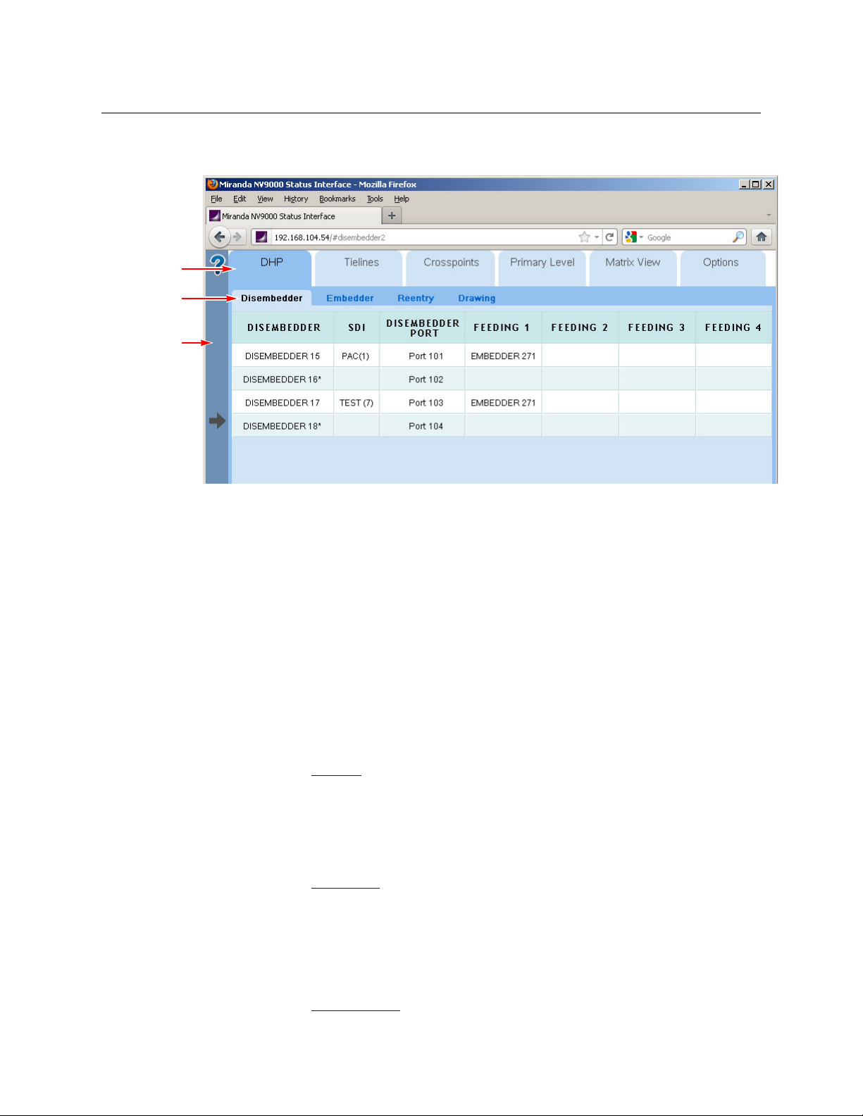
Tab s
Subtabs
Expandable
Help Pane
Summary
The Web Suite is divided into tabbed sections. Each tabbed section has subtabs and pages that
display when you click the subtabs:
The Web Suite does not, and cannot, communicate with an NV9000 system controller that is
in stand-by mode.
Although the Web Suite provides status for the entire NV9000 system, it can provide status
for only one router that uses DHP. The NV9000 system must have only one DHP service
running.
Tabbed Sections
The upper row of tabs selects a topic within the Web Suite. Presently there are 6 section types in
the upper row:
• DHP Management
For DHP, there are 4 subtabs:
DHP Disembedder DHP Embedder DHP Reentry DHP Drawing
There are no management functions in this topic. The DHP pages are simply status pages.
See Chapter 3, DHP Tab
• Tieline Management
For tielines, there are 3 subtabs:
Tieline Uses Tieline Destinations Tieline Drawing
There are no management functions in this topic. The tieline pages are simply status pages.
See Chapter 4, Tielines Tab
• Multi-Level View
The multi-level view displays NV9000 destinations in a table — one destination per row. The
columns of the table are the virtual levels (in the NV9000) you have selected. If the destination has a source routed to it on that level, the name of the source appears in that column for
that destination.
See Chapter 5, Multi-Level Tab
, on page 59, for details.
, on page 73, for details.
, on page 85, for details.
2
Page 13

NV9000 Web Suite
User’s Guide
• Primary Level View
The primary level view displays NV9000 destination/source pairs in a table. The source of the
pair is the one providing the signal on the destination’s primary level.
(Users can specify the number of pairs to be displayed in each row.)
See Chapter 6, Primary Level Tab
, on page 89, for details.
• Matrix View
The matrix view shows the NV9000’s sources and destinations as a 2-dimensional matrix,
where sources are columns of the matrix and destinations are rows in the matrix. Each matrix
element appears as a button that you can press to perform a take.
The page also has a listing of virtual levels (at the top). The matrix shows “crosspoint” connections on the levels that are selected in this region of the page.
Users may view the matrix and may actually perform takes, locks, protects, breakaways, or
level mapping using the controls present on the page.
See Chapter 7, Matrix View
, on page 93, for details.
• Options
The options tab allows you to configure the Web Suite itself and to see status regarding the
Web Suite itself.
See Chapter 2, Options Tab
Users can usually add tabbed pages of these types except another ‘Options’ tab.
, on page 17, for details.
Getting Started
Installation
The NV9000 Web Suite can be installed on PCs (under Windows XP or Windows 7). Persons who
Install the Web Suite should read the notice given in Appendix A
The installation procedure is brief. Follow these steps:
1 Obtain the Web Suite installer and place it on a USB device.
2Login to the PC
3 Insert the USB device in a USB slot on the PC.
4 Locate the web suite installer in the file structure of the USB device. Double-click it.
(The name of the installer is
similar.)
1
on which you are going to install the Web Suite.
nv9000-web-suite-installer-3.0.1435.29 or something
.
1. Use a PC. The Web Suite should never be installed on an NV9000 family system controller.
3
Page 14
Introduction
Getting Started
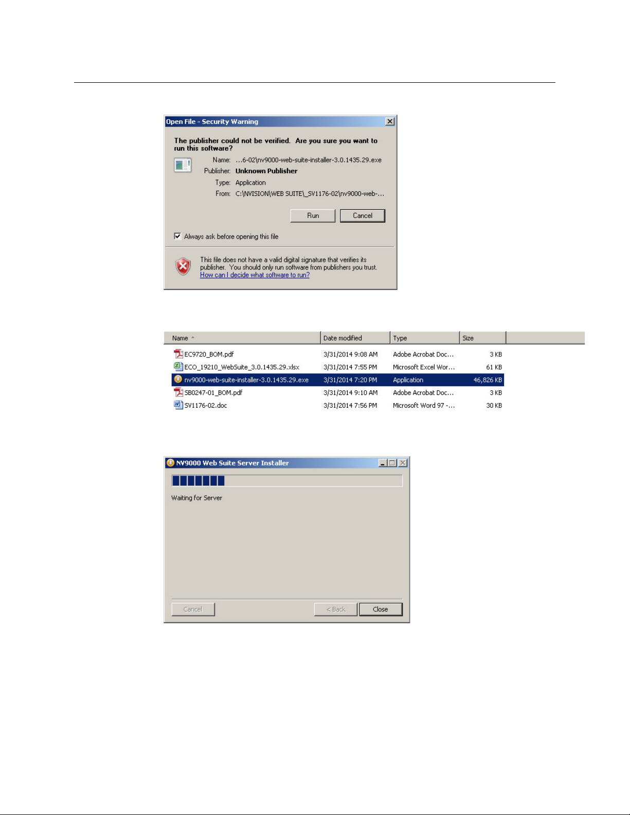
5 Windows presents a security warning:
Click ‘Run’ to proceed.
6 The installation process asks your permission to install the Web Suite:
Click ‘Yes’ to proceed.
7 The installation process displays a progress indication:
The installation takes only a few seconds.
4
Page 15
NV9000 Web Suite
User’s Guide
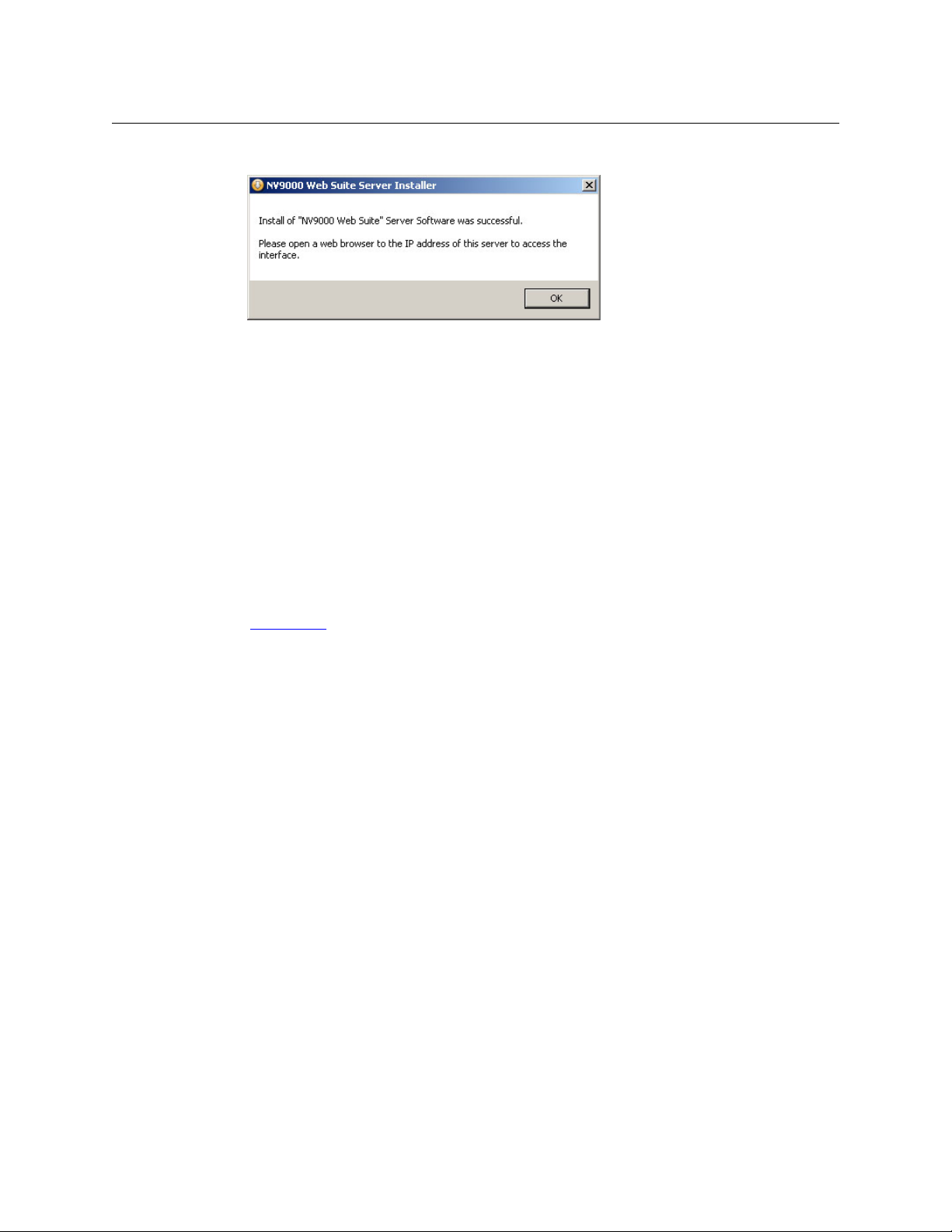
8 When the installation is complete, it tells you:
Managing the Service
The Web Suite is a service, not an application. As a service, it can be started, or stopped. By
default, it starts automatically when the PC starts up.
After you install the Web Suite, make sure that its status is either stopped, started, or automatic,
as appropriate for the PC:
• If the service is to provide DHP status among several PCs, the service for only one PC should
‘started’, For all other PCs that access the same system controller, the service should be
stopped.
• If the system controller does not use DHP, the service can be started or automatic on any
number of PCs.
Multiple PC users who monitor DHP can share a single instance of the Web Suite service.
See Appendix A
.
5
Page 16
Introduction
Getting Started
Changing the State of the Web Suite Service
If the service is already in the proper state, leave it alone.
To change the state of the service, follow these steps:
1 Right click the ‘My Computer’ icon, on the desktop of your PC, or the ‘NVConfig’ icon, on the
system controller. Choose ‘Manage’ from the context menu that appears.
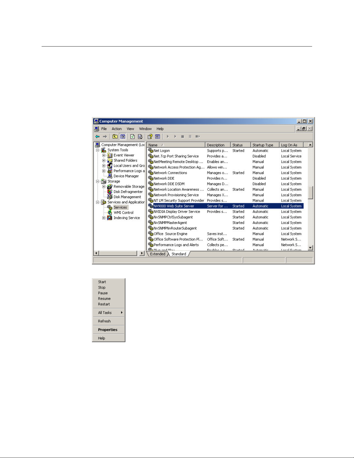
2 Choose ‘Services’ from the tree at the left. Then find ‘NV9000 Web Suite Server’ among the
services:
3 Right-click the highlighted line. A context menu appears:
Choose the appropriate command for the PC or system controller: start, stop, or properties.
(Commands that have no effect are greyed out.)
The start command starts a stopped service. (A stopped service shows no text in the status
column.)
The stop command stops a running service (which shows ‘Started’ in the status column).
6
Page 17
NV9000 Web Suite
User’s Guide
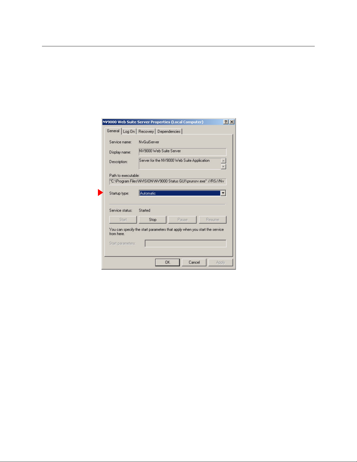
4 Ensure that the Web Suite’s ‘Startup Type’ is correct.
For PCs that reference system controllers that provide DHP, the ‘Startup Type’ should be
‘Manual’.
For system controllers, the ‘Startup Type’ column must show ‘Automatic’.
For PCs that do not reference system controllers that provide DHP, the ‘Startup Type’ should
be ‘Automatic’ for the convenience of the PC user who might restart that PC.
a Right-click the service and choose ‘Properties’ from the context menu:
b Choose either ‘Automatic’ or ‘Manual’ from ‘Startup Type’ field, as required.
7
Page 18
Introduction
Getting Started
Accessing the NV9000 Web Suite
The service functions in a browser on your PC.
Using your PC’s Service
Follow these steps:
1 Launch your browser (i.e., Firefox, Chrome, Internet Explorer 10).
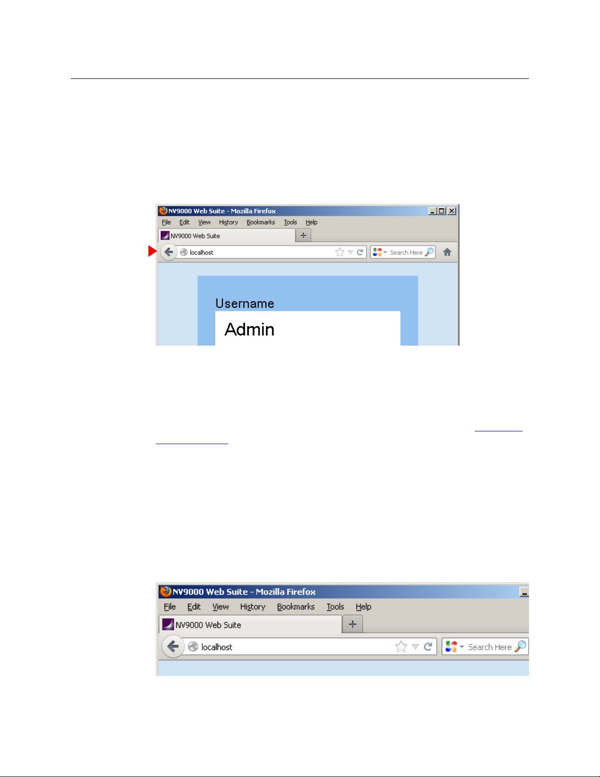
2 Type “localhost” in the URL field of the browser:
You can also type the IP address of your PC or the IP address of another PC on which the Web
Suite has been installed. The term “localhost” is a synonym for the IP address of your own PC.
In any case, specify the IP address of the PC on which the Web Suite is running.
The service should execute and display the login page of the Web Suite.
After you log in, there is one more step before the system controller’s data become accessible. That will be to type the NV9000’s IP address into a configuration page. See Choosing a
System Controller on page 10.
Logging In
Initially, the Web Suite is empty — having no configurations and identifying no users — and the
first task for administrators is to create a list of users and define at least one Web Suite configuration. (There is a default configuration.) After that task is done, the users you have named can use
the Web Suite with relative ease.
1 Ensure that the PC on which the Web Suite is installed has access to the Ethernet network of
the router control system you want to monitor.
2 Launch your browser and either enter “localhost” as the URL . . .
8
Page 19
NV9000 Web Suite
User’s Guide
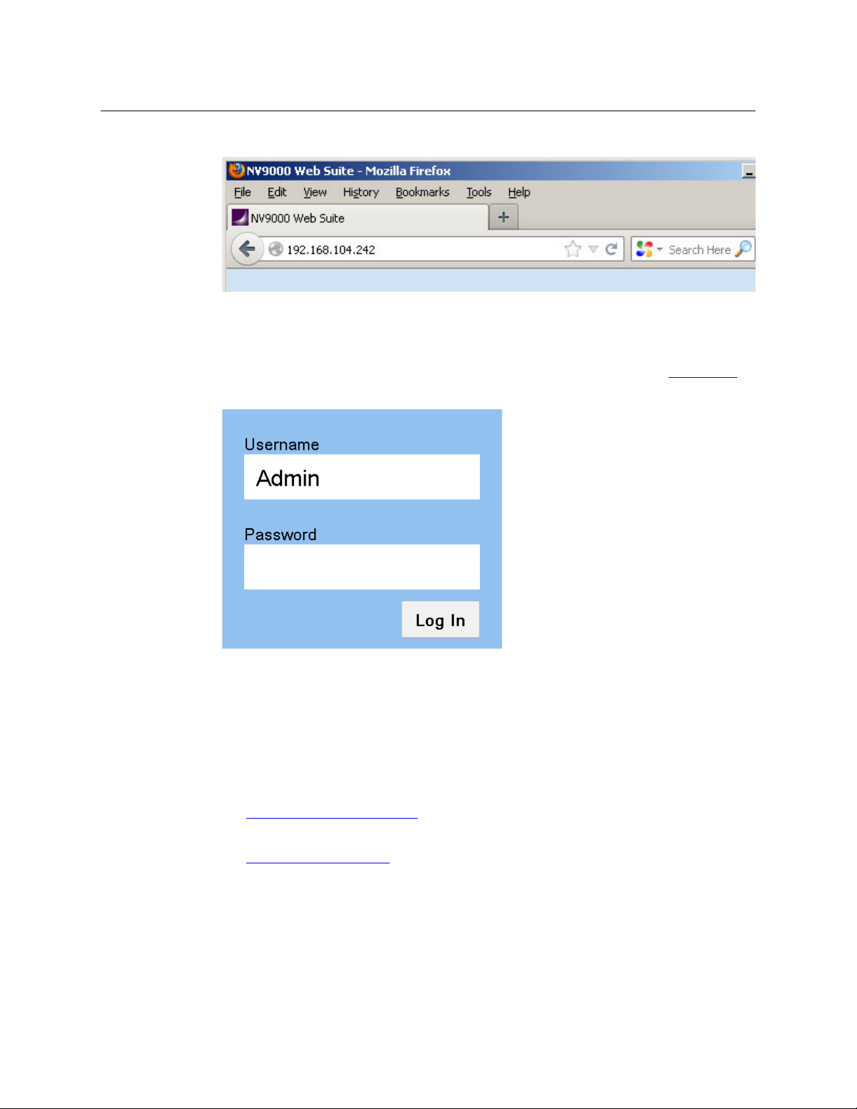
. . . or enter the IP address of a PC that is running the Web Suite service as the URL.
“Localhost” references your own PC. You could also enter your PC’s IP address, if you know it.
If you enter the IP address of someone else’s PC, you will be using the instance of the Web
Suite running on that PC.
Only one instance of the web suite may access DHP data at one time. See Appendix A.
3 In any case, given a valid IP address, the Web Suite presents a login dialog.
Log in using
Username = Admin
Password = nvision
“Admin” is a special user identity that exists only for the purpose of creating configurations
and adding users to the Web Suite’s list of users. (This identity always has admin privileges,
but cannot view any of the Web Suite’s status pages.)
4 First identify the system controller you want to monitor with the Web Suite.
See Choosing a System Controller
, following.
5 Create at least one Web Suite “configuration.”
See Creating a Configuration
, following.
9
Page 20
Introduction
Getting Started
6 Add at least one user (to the initially empty list of users). Include yourself in this list and give
yourself admin privilege.
See Adding a User
7 After you create a configuration and add one or more users, log out and log in as one of the
users you added to the list of users.
You cannot view the Web Suite status pages while you are logged in as ‘Admin’. You can continue to create configurations and add or delete users when you are logged in as a user having admin privilege.
on page 12.
Choosing a System Controller
You must first identify the system controller you want to monitor with the Web Suite.
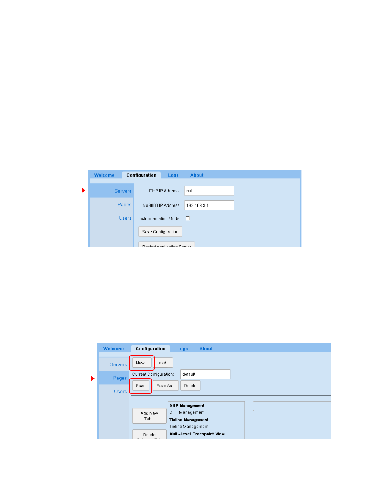
After you have logged in as ‘Admin’, click the ‘Configuration’ tab. Then click the word ‘Servers’:
Type the IP address of the system controller or the virtual IP address of a redundant pair of
system controllers in the ‘NV9000 IP Address’ field. (Whether your system controller is an NV960
or an NV920, its IP address goes here.)
Next, if the system controller controls a router that uses DHP, type the same IP address in the
DHP IP address field. Otherwise, type “null” in that field.
Last, click ‘Save Configuration’. Saving the configuration can take several minutes. If the save
takes more than a few minutes, restart your browser and reacquire the Web Suite.
Creating a Configuration
1 Choose the ‘Configuration’ tab and select ‘Pages’
10
Page 21
NV9000 Web Suite
User’s Guide
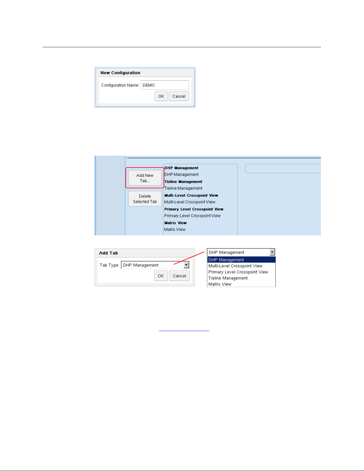
2 Click the ‘New . . .’ button. A ‘New Configuration’ dialog appears:
3 Enter a configuration name. Click ‘OK’.
4 At this point, there is a new configuration. The configuration is empty. It defines no tabbed
pages.
5 You can add tabbed pages, of 5 types, to this configuration and you can add as many of each
type as you want. To add a tabbed page, click ‘Add New Tab . . .’ in the middle of the page:
A dialog appears in which you can select a tab type:
Choose a tab type and click ‘OK’.
The new tab and any others you create appear in a list in the order you create them. (If you
make a mistake, click on the tab’s list entry and then click the ‘Delete Tab’ button.
6 You could edit the configuration you created, but it is not essential to do so at this time. If
you wish to do so, refer to Configuration Pages
on page 19 for more information.
7 Finally, click the ‘Save’button.
11
Page 22
Introduction
Getting Started
Adding a User
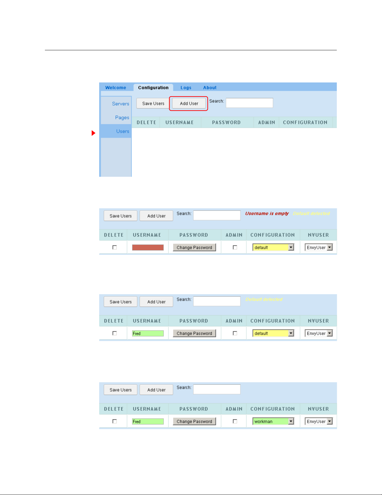
1 Choose the ‘Configuration’ tab and select ‘Users’:
The large white area is empty at first. As you add users, it is filled with rows of data for the
users you have defined.
2 Click the ‘Add New User.’ button. A new row appears in the table:
The ‘Username’ field is filled with red and a message appears at the top right: “Username is
empty.” This message is a prompt for you to click in the ‘Username’ field and enter a user
name. When you do (and follow the entry by pressing ‹enter› or ‹tab›) the field turns green
and the prompt disappears:
The ‘Configuration’ field for this user is set to the default and the field is therefore yellow. You
should choose a configuration other than the default, but you are not required to do so. This
field can be changed at any time.
if you do change the configuration field, the field turns green as the ‘Username’ field did:
12
Page 23
NV9000 Web Suite
User’s Guide
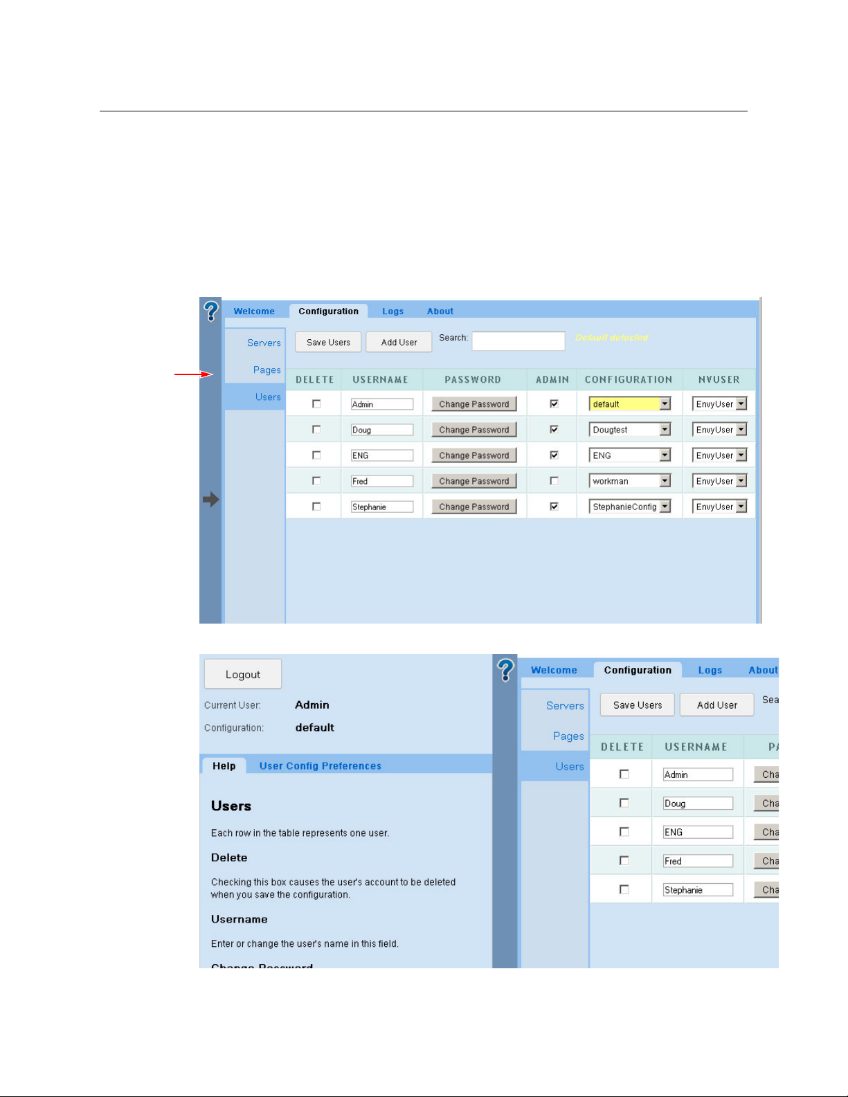
3 Finally, click ‘Save Users’. After a confirmation dialog, the new user data are accepted, and the
display refreshes:
When multiple users are identified, the rows are ordered by user name.
4 You can also designate whether users have admin privilege in check boxes of the ‘Admin’
column.
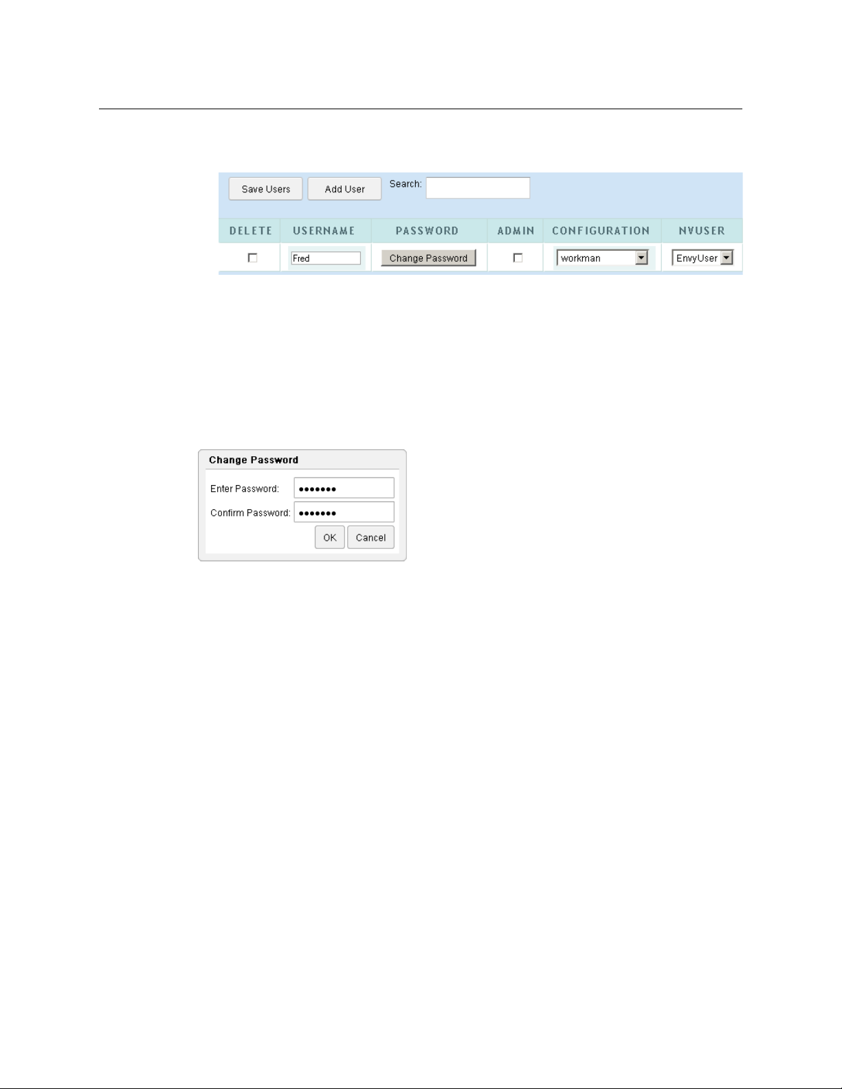
Changing a Password
By default, when you add new users, they will require no password to log in.
If you want to require a password from a user, click the ‘Change Password’ button for that user. A
dialog appears:
Enter the password, repeat it, then click OK. Click cancel if you do not want to enter a password.
You cannot recover this password if you forget it. But you can always enter a new password
(if you can log in with admin privilege).
User IDs
NV9000-SE Utilities allows persons configuring the router control system to define user IDs. User
IDs are normally associated with control panels.
In NV9000-SE Utilities, user IDs are alphanumeric strings that usually form readable names.
The Web Suite allows you to associate any user name defined in the NV9000 router control
system with a user in the list. There are drop-down lists in the NVUSER column from which you
can choose a user name. The NV9000 user name and its database ID are subsequently used to
indicate which user has issued a lock or a protect on destinations in the router control system.
It is advisable to have all NV9000 user names defined (in NV9000-SE Utilities) and assigned
(in the Web Suite) at the earliest opportunity. Users who perform locks and protects under
one NV9000 user name cannot release those locks and protects if they change to a different
NV9000 user name.
Saving the User List
If you made a mistake before you save, you can discard the mistake by clicking your browser’s
refresh button. Doing so reloads the saved user list from the NV9000 database. (The Web Suite
will warn you about losing the changes you made.)
13
Page 24
Introduction
Blue
bar
Help Pane
Help Pane
Logging Out
Log out (as Admin) and log in using your own user name and password.
Use the expandable help pane (described next) to log out.
At the left side of the Web Suite window is a blue bar with a large question mark at the top and
an arrow in the middle:
Click on this blue bar to expand the collapsed “sidebar” pane:
The blue bar slides to the right (when you open the pane).
14
Page 25

If you click the bar again, it slides to the left to close the pane.
The pane presents some information about the Web Suite, principally, the user name and
configuration you are currently using.
The pane also offers some help regarding the particular page in which you are working.
The pane also allows you to set certain preferences for the page in which you are working. The
preferences differ according to the page. This document describes the preferences in the
sections that describe that pages.
Logging Out
Click the ‘Logout’ button to log out. After you log out, the Web Suite immediately displays the
login dialog (shown on page 9).
Usage Notes
Creating Tabbed Pages
Users with admin privilege can create new tabbed pages and modify the display options of
existing pages. Refer to the ‘Pages’ Page
found under the ‘Options > Configuration’ subtab.
NV9000 Web Suite
User’s Guide
on page 23 for information. The ‘Pages’ page can be
Display Lists
In the multi-level configuration page, the primary level configuration page, and some of the
other configuration pages, you can select a set of levels and a set of destinations and sources for
display. You can use standard click, shift-click, and control-click methods to select levels or destinations in the configuration pages.
In addition, you can place the levels and destinations in lists in any arbitrary order by using the
‘Move Up’ and ‘Move Down’ buttons in those configuration pages. The move buttons affect
whatever list entries you have selected.
(See Editing a Multi-Level Crosspoint Tab
page 41.)
Similarly, you can define a list of tielines for which to display status in a tielines page. See Editing
a Tieline Tab on page 33.
Similarly, you can define a list of disembedders and a list of embedders for which to display
status in a DHP page. See Editing a DHP Tab
Ordering
In the configuration pages, it is possible to specify the ordering of entries in a displayed table.
The fields for the specification of displayed lists have ‘Move Up’ and ‘Move Down’ buttons that
you can use to reposition selected items within a list.
Further, users can click the header of a column in a displayed table to cause the reordering of
the table according to the entries in that column. Users may click the header once to get
ascending order; they may click the column again to get descending order.
on page 36 and Editing a Primary Level Tab on
on page 28.
15
Page 26

Introduction
Usage Notes
Navigation
You can lose recently entered configuration data if you switch pages (without saving). The Web
Suite will warn you if you leave a page without saving data. However, if you use the ‘back’ and
‘forward’ buttons of your browser, you can jump from page to page without losing data.
(In most browsers) pressing backspace on you keyboard has the same effect as switching
pages. Be careful not to press backspace accidentally!
Takes
When a control panel operator performs a take, and the destination affected by the take is
displayed in your Web Suite window, the background of the table row or table cells for the destination turns green momentarily and then fades back to white over a period of a few seconds.
Note that this phenomenon occurs only in the multi-level and primary level views.
Locks and Protects
In the multi-level’ and primary level pages, the table entries for destinations that are locked are
colored red. The table entries for destinations that are protected are colored yellow.
In the matrix view, the matrix buttons (round-corner squares) are colored red for locked destinations and are colored yellow for protected destinations.
Long Dashes in Tables
For systems with routers that are offline, many table entries that would normally appear with
source names (or other data) are void of data and have a long dash in the field.
Multi-level pages also show long dashes for levels that do not apply to the destinations listed on
the page.
There is no way to distinguish a source that does not apply from a source that exists in a router
that is offline. The best way to interpret the long dash is that it means “there is no applicable
source name.”
The same can be said about the string “--------” (8 dashes) in source name fields. This also means
“there is no applicable source name.” (The 8-dash string is generated by the system controller.)
16
Page 27
Subtabs
Options Tab
Chapter 2 provides information and instructions regarding the Web Suite’s ‘Options’ tab.
Topics
Subtabs . . . . . . . . . . . . . . . . . . . . . . . . . . . . . . . . . . . . . . . . . . . . . . . . . . . . . . . . . . . . . . . . . . . . . . . . . . . . . . . . . . 17
Configuration Pages . . . . . . . . . . . . . . . . . . . . . . . . . . . . . . . . . . . . . . . . . . . . . . . . . . . . . . . . . . . . . . . . . . . . . . 19
Log Pages . . . . . . . . . . . . . . . . . . . . . . . . . . . . . . . . . . . . . . . . . . . . . . . . . . . . . . . . . . . . . . . . . . . . . . . . . . . . . . . . 55
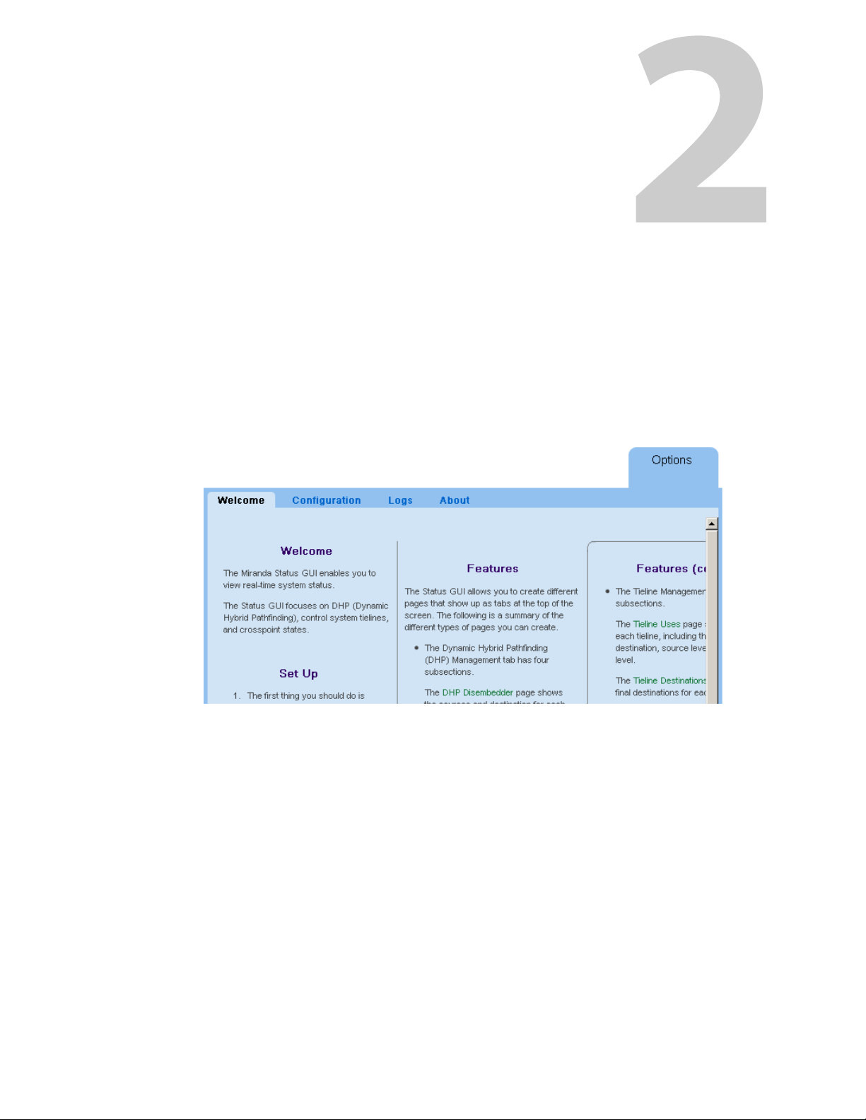
The ‘Options’ tab has 4 subtabs.
These are the subtabs and their pages:
• Welcome • Logs
• Configuration • About
Welcome
The ‘Welcome’ page offers brief setup instructions and brief descriptions of the various Web
Suite pages.
Configuration
The ‘Configuration’ page allows you to create new views of NV9000 data and to customize
existing views. You can create and save different Web Suite configurations.
(You must be logged in as a user with “admin” privilege to modify the Web Suite. Alternatively,
you can log in as ‘Admin’.)
17
Page 28

Options Tab
Subtabs
Three Kinds of Configuration
There are 3 kinds of configuration in the ‘Configuration’ tab:
• Configuration of the NV9000 Web Suite (i.e., the “server”).
Changes made to your Web Suite configuration are made in the Servers Page
uration’ subtab.
Saving changes to this type of configuration causes the NV9000 Web Suite (the “server”) to
restart. The restart can take several minutes.
The “server” that is running in your browser is the one you selected in your browser. That is, it
is either the service running on your PC or it is the service running on someone else’s PC.
(See Accessing the NV9000 Web Suite
on page 8.)
• Adding and removing users.
These configurations are created and modified in the Users Page
tab.
Changes to these configurations do not cause the Web Suite service to restart.
of the ‘Configuration’ sub-
• Configuration of the Web Suite pages.
These configurations are created and modified in the ‘Pages’ Page
tab. These configurations affect the display of DHP data, tieline data, and crosspoint data.
You can create many (tabbed) pages in which to view NV9000 data and there are configuration parameters for each page you create. Changes to these configurations do not cause the
Web Suite service to restart.
Every user is assigned one configuration, even if it is only the default configuration, in the
Users Page
own Web Suite configuration and modify the configuration as needed.)
Changes to the data page configurations affect the display of data pages for the user in
whose name you are logged in. (Generally, the page configurations are your own, but it is
possible for you to be working on someone else’s behalf.)
of the ‘Configuration’ subtab. (A user with admin privilege can choose his or her
of the ‘Configuration’ sub-
of the ‘Config-
18
Logs
The ‘Logs’ subtab has 4 pages. The last page — ‘Data Store’ — are available only when the Web
Suite is in instrumentation mode:
• Server Log
The ‘Server Log’ page presents event history for the Web Suite server.
See Server Log Page
• Client Log
The ‘Client Log’ page presents event history for the NV9000 Web Suite client.
See Client Log Page
• System Status
The ‘System Status’ page presents statistics about the Web Suite.
See System Status
• Data Store
The ‘Data Store’ page shows the values for data within the Web Suite.
See Data Store Page
on page 56.
on page 56.
on page 55.
on page 58.
Page 29
About
The ‘About’ page presents contact information, Miranda’s website address, legal notices, and
the current revision number of the Web Suite.
The data presented reference the service you have selected in your browser, that is the service
running on your PC.
Configuration Pages
The ‘Configuration’ subtab is the most important subtab of the ‘Options’ tab.
If you have “admin” privilege, you can add and delete Web Suite configurations, add and delete
user IDs, and create new and alternate views (i.e., new tabs) of NV9000 data.
The ‘Configuration’ subtab has 3 pages:
• Servers
Use this page to set up the Web Suite service you are using.
• Pages
Use this page to create new configurations, create new tabs, and to modify the views of new
and existing tabs.
• Users
Use this page to add and delete user IDs, or to change users’ passwords, and to assign configurations to users.
NV9000 Web Suite
User’s Guide
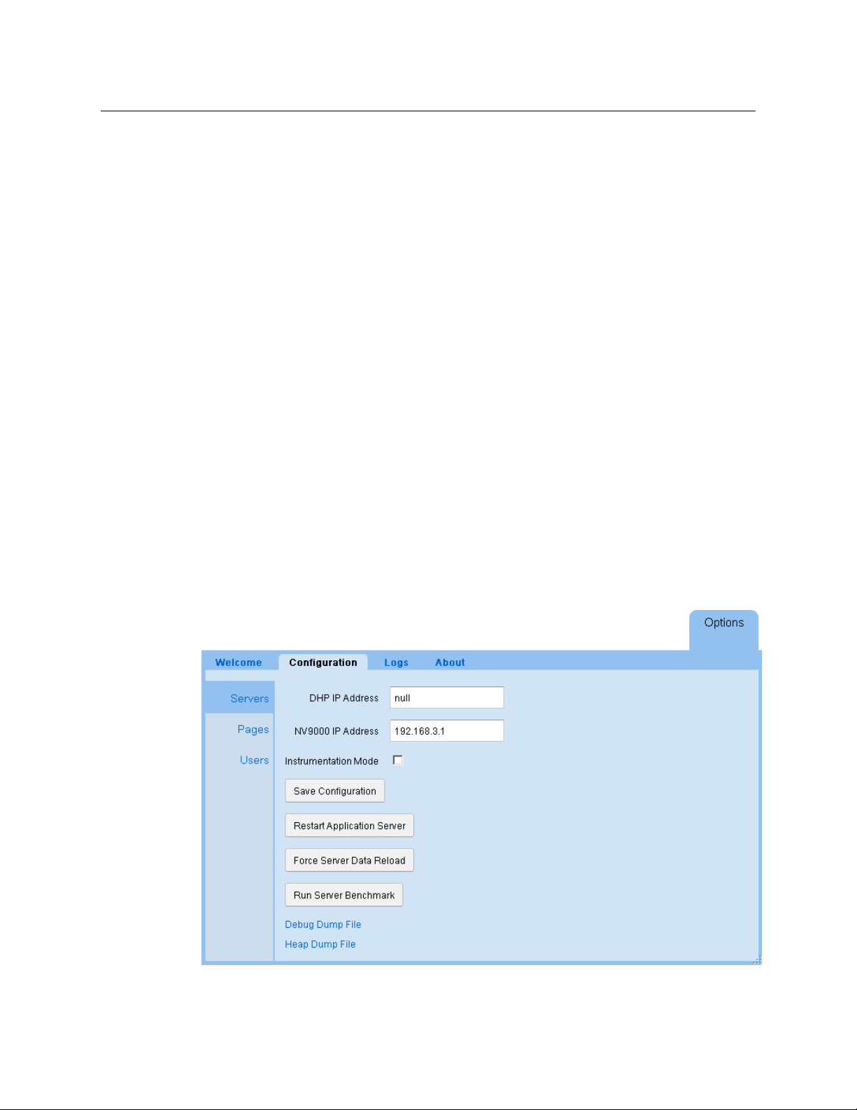
Servers Page
The ‘Servers’ page lets you modify the configuration of the Web Suite service you have selected:
Use caution if you modify any of the entries in this page.
19
Page 30

Options Tab
Configuration Pages
Modifications to any of these fields do not take effect until you click the ‘Save Configuration’
button and the Web Suite service subsequently restarts.
If you make a modification to any field, it turns green or has a green outline until you have saved
the Web Suite configuration.
Note: saving the server’s (i.e., the Web Suite’s) state causes the server to restart. That might take
several minutes.
Descriptions of the fields, buttons, and other items in this page follow.
If you click the large blue bar at the left of the page (not shown here), the help pane expands
to reveal short help messages regarding the options in this page.
NV9000 IP Address
This is the IP address of the system controller (NV960 or NV920) to which you are connected or
the virtual IP address of a redundant pair of system controllers.
DHP IP Address
If your system controller supports a router that uses DHP, place the system controller’s IP address
in this field too. If your system controller does not support DHP, enter “null” in this field.
Reminder: DHP allows only one Web Suite connection to be started at any time.
Instrumentation Mode
Place a check mark in this check box if you wish to place the Web Suite in “instrumentation”
mode.
When the Web Suite is in instrumentation mode, all 4 of the pages of the ‘Logs’ subtab under
the ‘Options’ tab are enabled. When instrumentation mode is off, only 3 logging pages are available. Instrumentation mode also enables more detailed logging.
Save Configuration Button
Click this button to save the Web Suite setup to your PC.
When you save, the Web Suite restarts and your browser refreshes. A restart can take several
minutes.
Restart Application Server Button
Click this button to restart the Web Suite service you have selected. A restart can take several
minutes.
The service being restarted will be unavailable to you (or to others) during this time.
Force Server Data Reload Button
The data affected by this button are what the Web Suite displays. This button tells the server to
reload all the data it collects from all sources.
20
Page 31

NV9000 Web Suite
User’s Guide
Run Server Benchmark
Click this button to get a report about the performance of your Web Suite server. The report has
this format:
Debug Dump Files
At the bottom of the servers page are 2 options:
• Debug dump file
• Heap dump file
Click either option to save a dump file. The debug dump file has the extension .nvdat. The heap
dump file is a .zip file.
Save these file only if you in a debug situation and in communication with a Miranda technician.
You will be asked to send these files to Miranda. The data in these files are not readable. We
recommend that you do not attempt to open these files after you have saved them.
The method for saving dump files varies according to the browser you are using.
Firefox Behavior
If you are using Firefox, this is the dialog that appears when you click ‘Debug Dump File’ or
‘Heap Dump File’:
To save the debug information to a file, choose ‘Save File’. Then, in the navigation dialog that
follows, select a location and a name for the file.
Do not choose ‘Open with’.
21
Page 32

Options Tab
Configuration Pages
Chrome Behavior
When you click ‘Debug Dump File’ or ‘Heap Dump File’, Chrome saves the file in a specific folder.
Under Windows, the default folder is
the default folder is
‹diskname›/‹username›/downloads.
C:\users\‹username›\downloads. Under the Mac OS,
The indication that Chrome has saved the file is that it displays the file name in the lower left
corner of its window:
Safari Behavior
When you click ‘Debug Dump File’ or ‘Heap Dump File’, Safari saves the file in a specific folder.
The default folder is
The indication that Safari has saved the file is that it briefly displays an animation that targets its
download button. If you click the download button, you will see a list of downloaded files, the
dump file being among the most recent. Right-click the dump file to get a context menu:
‹diskname›/‹username›/downloads.
22
Click ‘Show in Finder’ in the context menu to locate the file. The OS will display a window giving
the file’s location.
Page 33

NV9000 Web Suite
User’s Guide
‘Pages’ Page
The ‘Pages’ page allows you (1) to create new configurations and (2) to create or modify different
tabbed pages in a selected configuration. The tabbed pages show differing views of NV9000
data. (You need admin privilege to create configurations or additional tabbed pages.)
The page for the default Web Suite configuration has 5 tabs defined.
The 5 bold headings identify the 5 different page configurations in the default configuration.
When you click one of the headings, the configuration options for tab that appear in the page.
23
Page 34

Options Tab
Configuration Pages
The page for new configurations, however, is empty (i.e, it defines no tabbed pages):
The ‘Add Tab . . .’ button creates tabbed pages. The ‘Delete Tab’ button removes tabbed pages
that you have created.
Managing Configurations
These are the 5 configurations buttons at the top of the ‘Pages’ configuration page:
• New
Click this button to create a new Web Suite configuration. A dialog appears in which to specify the configuration name:
Enter a name and click ‘OK’.
The new configuration cannot be used until you save it. After saving it, you can load it for
editing or assign it to users. You can edit the configuration at any time and you can delete
the configuration at any time.
24
Page 35

NV9000 Web Suite
User’s Guide
• Load . . .
Click this button to load an existing Web Suite configuration. A dialog appears in which to
specify the configuration name:
• Save
Click this button to save the Web Suite configuration you have been editing. A dialog
appears in which you must confirm that you wish to save the configuration:
• Save as . . .
Click this button to save an existing Web Suite configuration as another configuration. You
can also use this button to save a new configuration. A dialog appears in which to specify
the new configuration name:
Click ‘OK’. Then respond affirmatively to the confirmation message.
• Delete
Click this button to delete the configuration that you have loaded. Then respond affirmatively to this confirmation message:
(If the configuration is presently assigned to a user, you will not be allowed to delete it. The
message is “Error: configuration is assigned to a user
— cannot delete.”)
25
Page 36

Options Tab
Added
Tab
Configuration Pages
Adding Tabbed Pages
You can create additional tabbed pages and delete any that you have created.
Click ‘Add Tab . . .’ to create a tabbed page. A dialog appears in which you can name the page:
Choose one of the 5 tab types in the drop-down menu. These are
• DHP Management
• Tieline Management
• Multi-Level Crosspoint View
• Primary Level Crosspoint View
• Matrix View
When you choose a tab type, the new tab appears at the bottom of the page list. Added (or
modified) tabs are highlighted in green. Selected tabs are highlighted in blue. Click the new tab
to change its name and edit its parameters:
You can click the ‘Save’ button, at the top of the screen, at any time to save the changes you
have made. (Respond affirmatively to the confirmation message that appears when you save.)
(You could also click ‘Save as . . .’)
26
Page 37

NV9000 Web Suite
Added
Tab
User’s Guide
After you save, the newly added tab appears in the list of tabs normally, with its new name:
Ordering Tabbed Pages
You can cause the tabs to appear in your Web Suite window in any order you like.
To position a tabbed page in the ordering, click the name of the page in the list of pages. Then
click the ‘Move Up’ or ‘Move Down’ button one or more times so that it is in the desired place (or
near to the desired place).
These are the ‘Move Up’ and ‘Move Down’ buttons directly below the tabbed page list. There
are other ‘Move Up’ and ‘Move Down’ buttons elsewhere on the page. Those are for reordering the lists you have defined for a page.
Repeat this process for other pages until all the pages in the list are in the desired order.
The ordering takes effect the next time you click ‘Save’ (or ‘Save As . . .).
Deleting Tabbed Pages
Select the tab you want to delete in the list of tabs at the left.
Click the ‘Delete Tab’ button.
The tab and its parameter fields become highlighted in gray:
27
Page 38

Options Tab
Configuration Pages
Click the ‘Save’ button to complete the deletion. The configuration is redisplayed, now without
the tabs that were deleted.
If you change your mind about deleting a tab, there is no direct way to unselect tabs marked for
deletion. To cause the tab(s) to become unselected, switch momentarily to another page of the
Web Suite and return to the ‘Page’ page. The tabs will appear normally
— unselected.
Editing a DHP Tab
You can control the appearance and content of a DHP tab by editing its parameters in the
‘Pages’ configuration page.
A DHP tab has up to 4 sub tabs:
Disembedder Embedder Reentry Drawing
You can also control the appearance of any of these subtabs by indicating your preferences on
the sidebar of a particular DHP subtab when the subtab is displayed. (Click the blue bar at the
left of the Web Suite window to reveal the sidebar.)
Click on a DHP tab in the list of tabs at the left of the ‘Pages’ configuration page. The DHP tab
entry becomes highlighted and the DHP tab configuration fields of the page appear:
28
Use the check boxes at the right to enable or disable the display of any of the four DHP subtabs.
Specify the names (or titles) of the subtabs in the fields just to the left of the check boxes. You
can specify the title of the DHP tab as well.
Page 39

NV9000 Web Suite
User’s Guide
Check the ‘Show Port Numbers’ check box if you want the DHP subtabs to display port numbers
in addition to port names.
You can click the ‘Save’ button at any time to retain your changes.
Disembedders to Show
Below the fields for the names of the DHP subtabs is a region in which you can specify for which
of DHP’s disembedders the Web Suite displays status. In this section are two radio buttons:
• Use All
• Use Selection
The default choice is ‘Use All’ as shown in the preceding illustration. In this case, the Web Suite
provides status for all disembedders and embedders that are defined in the NV9000 system at
the time the page is displayed.
Choose ‘Use Selection’ in the ‘Disembedders to Show’ region if you want to specify which
disembedders the DHP subtabs are to report. The ‘Disembedders to Show’ region expands to
allow you to form the disembedder selection:
The ‘Use Selection’ fields include filtering options. See Filter Options for Disembedders
,
following.
The items on the left
— under “Don’t Include”— are the disembedders that do not appear in the
DHP subtabs.
The items on the right
— under “Include”— are the disembedders that do appear in the DHP
subtabs.
To move disembedders from the “Don’t Include” list to the “Include” list, select one or more
entries in the “Don’t Include” list and click the ‘Append >‘ button or click ‘Append All >>’.
To move disembedders from the “Include” list to the “Don’t Include” list, select one or more
entries in the “Include” list and click the ‘< Remove‘ button or click ‘<< Remove All’.
29
Page 40

Options Tab
Configuration Pages
Click ‘Append Blank Entry’ if you want to create a blank line that functions as a separator in your
‘Include’ list. The separator can help you organize the list. The separator also creates a blank row
in the table that is displayed in the page (or pages) of the tab you are editing.
Use the ‘Move Up’ and ‘Move Down’ buttons under the “Include” list to reorder the disembedders. Select one or more disembedders in the “Include” list and click ‘Move Up’ or ‘Move ‘Down’
as appropriate to create the ordering you want.
Filter Options for Disembedders
Click the triangle for the ‘Filter Options’ to expose the filter options:
There is one option: a ‘Search’ field. If you specify some text in the ‘Search’ field, the filter use a
substring matching method: if the substring you enter as the filter appears in the disembedder
name or its ID, the disembedder can be in the lists.
The filter ignores the search field if it is blank.
30
Page 41

NV9000 Web Suite
User’s Guide
Embedders to Show
Below the fields for the names of the DHP subtabs is a region in which you can specify for which
of DHP’s embedders the Web Suite displays status. In this section are two radio buttons:
• Use All
• Use Selection
The default choice is ‘Use All’ as shown in the illustration above. In this case, the Web Suite
provides status for all embedders that are defined in the NV9000 system at the time of the status
report.
Choose ‘Use Selection’ in the ‘Embedders to Show’ region if you want to specify which embedders the DHP subtabs are to report. The ‘Embedders to Show’ region expands to allow you to
form the embedder selection:
The ‘Use Selection’ fields include filtering options. See Filter Options for Embedders
The items on the left
DHP subtabs. The items on the right
— under “Don’t Include”— are the embedders that do not appear in the
— under “Include”— are the embedders that do appear in
, following.
the DHP subtabs.
To move embedders from the “Don’t Include” list to the “Include” list, select one or more entries
in the “Don’t Include” list and click the ‘Append >‘ button or click ‘Append All >>’.
To move embedders from the “Include” list to the “Don’t Include” list, select one or more entries
in the “Include” list and click the ‘< Remove‘ button or click ‘<< Remove All’.
Click ‘Append Blank Entry’ if you want to create a blank line that functions as a separator in your
‘Include’ list. The separator can help you organize the list. The separator also creates a blank row
in the table that is displayed in the page (or pages) of the tab you are editing.
Use the ‘Move Up’ and ‘Move Down’ buttons under the “Include” list to reorder the embedders.
Select one or more embedders in the “Include” list and click ‘Move Up’ or ‘Move ‘Down’ as
appropriate to create the ordering you want.
31
Page 42

Options Tab
Configuration Pages
Filter Options for Embedders
Click the triangle for the ‘Filter Options’ to expose the options:
There is one option: a ‘Search’ field. If you specify some text in the ‘Search’ field, the filter use a
substring matching method: if the substring you enter as the filter appears in the embedder
name or its ID, the embedder can be in the lists.
The filter ignores the search field if it is blank.
Copy and Paste Buttons
The ‘Copy’ and ‘Paste’ buttons allow you to transfer page configuration data from one tab to
another tab.
It is not possible to copy the lists from the Web Suite to another application such as Notepad or
Excel.
Data for the configuration of DHP pages are not applicable in any other Web Suite page.
Although you can “copy” DHP data, the ‘Paste’ button remains disabled in all other pages.
32
Page 43

NV9000 Web Suite
User’s Guide
Editing a Tieline Tab
You can control the appearance and content of a tieline tab by editing its parameters in the
‘Pages’ configuration page.
A tieline tab has up to 3 sub tabs:
Tieline Uses Tieline Destinations Tieline Drawings
You can also control the appearance of any of these subtabs by indicating your preferences on
the sidebar of a particular tieline subtab when the subtab is selected. (Click the blue bar at the
left of the Web Suite window to reveal the sidebar.)
Click on a tieline tab in the list of tabs at the left of the ‘Pages’ configuration page. The tieline tab
entry becomes highlighted and the tieline tab configuration fields of the page appear:
Use the check boxes to enable or disable the display of any of the three tieline subtabs.
Specify the names (or titles) of the subtabs in the fields just to the left of the check boxes. You
can specify the name of the tieline tab as well.
Check the ‘Show Port Numbers and Level/Tieline IDs’ check box if you want the subtabs to
display port numbers in addition to port names and level IDs and tieline IDs.
You can click the ‘Save’ button at any time to retain your changes.
33
Page 44

Options Tab
Configuration Pages
Tielines to Show
Below the fields for the names of the tieline subtabs is a region in which you can specify for
which tielines the NV9000 Web Suite displays status. In this section are two radio buttons:
• Use All
• Use Selection
The default choice is ‘Use All’ as shown in the illustration above. In this case, the Web Suite
provides status for all tielines that are defined in the NV9000 system at the time the page is
displayed.
Choose ‘Use Selection’ in the ‘Tielines to Show’ region if you want to specify which tielines the
tielines tab is to report. The ‘Tielines to Show’ region expands to allow you to form the tieline
selection:
34
The ‘Use Selection’ fields include filtering options. See Filter Options for Tielines
The items on the left
— under “Don’t Include”— are the tielines that do not appear in the tielines
, following.
tab.
The items on the right
— under “Include”— are the tielines that do appear in the tielines tab.
To move tielines from the “Don’t Include” list to the “Include” list, select one or more entries in
the “Don’t Include” list and click the ‘Append >‘ button or click ‘Append All >>’.
To move tielines from the “Include” list to the “Don’t Include” list, select one or more entries in
the “Include” list and click the ‘< Remove‘ button or click ‘<< Remove All’.
Click ‘Append Blank Entry’ if you want to create a blank line that functions as a separator in your
‘Include’ list. The separator can help you organize the list. The separator also creates a blank row
in the table that is displayed in the page (or pages) of the tab you are editing.
Use the ‘Move Up’ and ‘Move Down’ buttons under the “Include” list to reorder the tielines.
Select one or more tielines in the “Include” list and click ‘Move Up’ or ‘Move ‘Down’ as appropriate to create the ordering you want.
Page 45

NV9000 Web Suite
User’s Guide
Filter Options for Tielines
Click the triangle for the ‘Filter Options’ to expose the options:
The filter has 2 parts: a tieline is included in the lists if it meets both criteria.
If you specify some text in the ‘Search’ field, the filter use a substring matching method: if the
substring you enter as the filter appears in the tieline name or its ID, the tieline can be in the lists.
If you choose a tieline group in the ‘Tieline Group’ drop-down list, the list is restricted to those
tielines that belong to the specified group.
The filter ignores the search field if it is blank. It ignores the group criterion if you choose
‘Display All’.
Note that your system might not have tieline groups. In that case, ‘Display All’ is the only
option in the drop-down list.
Copy and Paste Buttons
The ‘Copy’ and ‘Paste’ buttons allow you to transfer page configuration data from one tab to
another tab.
It is not possible to copy the lists from the Web Suite to another application such as Notepad or
Excel.
Data for the configuration of tieline pages are not applicable in any other Web Suite page.
Although you can “copy” tieline data, the ‘Paste’ button remains disabled in all other pages.
35
Page 46

Options Tab
Configuration Pages
Editing a Multi-Level Crosspoint Tab
You can control the appearance and content of a multi-level crosspoint tab by editing its parameters in the ‘Pages’ configuration page.
A multi-level crosspoint tab has no subtabs.
You can also control the appearance of the tab by indicating your preferences on the sidebar of
when the tab is selected. (Click the blue bar at the left of the Web Suite window to reveal the
sidebar.)
To edit a multi-level crosspoint tab, click on a multi-level crosspoint tab in the list of tabs at the
left of the ‘Pages’ configuration page. The multi-level crosspoint tab entry becomes highlighted
and the multi-level configuration fields of the page appear:
36
You can specify the name (or title) of the multi-level crosspoint tab.
There are several editing options. There are two check boxes that control how sources are
displayed. There are 4 radio buttons in two regions.
The first region is for the levels that this particular multi-level page displays. The multi-level page
can display data either for all levels or for selected levels. (There is a table column for each level
displayed.) If you choose ‘Use Selection’, the region expands to allow you to form the level selection. See Level Selection
The second region is for the destinations to be displayed. The page can display data for all destinations or for selected destinations. (There is a table row for each destination displayed.) If you
choose ‘Use Selection’ in this region, the region expands to allow you to form the destination
selection. See Destination Selection
You can click the ‘Save’ button at any time to retain your changes.
, following.
, following.
Page 47

NV9000 Web Suite
User’s Guide
Source Options
There are two check boxes that control how sources are displayed:
• Show Virtual Level of the Source.
• Show Device IDs.
These options are unchecked by default.
The rows of the table in a multi-level display represent destinations. The columns of the table
represent the destinations’ virtual levels.
The ‘Show Virtual Level of the Source’ check box causes the name of the virtual level of the
source to appear in (non-null) table entries. This is useful for breakaway situations.
The ‘Show Device IDs’ check box causes the NV9000 device ID to appear in the (non-null) table
entries. Device IDs are useful if the NV9000 configuration has duplicate source names. Device
IDs cannot ever be duplicated.
Level Selection
Choose ‘Use All’ in the ‘Levels’ region if you want the multi-level display to report sources for all
NV9000 virtual levels, regardless of what those levels are. The NV9000 configuration could
change, adding or deleting virtual levels, and your multi-level page will adjust.
Choose ‘Use Selection’ in the ‘Levels’ region if you want to specify which levels the table is to
report. The ‘Levels’ region expands to allow you to form the level selection:
The ‘Use Selection’ fields include filtering options. See Filter Options for Levels
The items on the left
— under “Don’t Include”— are the virtual levels that do not appear in the
multi-level page.
, following.
37
Page 48

Options Tab
Configuration Pages
The items on the right — under “Include”— are the virtual levels that do appear in the multi-level
page.
To move levels from the “Don’t Include” list to the “Include” list, select one or more entries in the
“Don’t Include” list and click the ‘Append >‘ button or click ‘Append All >>’.
To move levels from the “Include” list to the “Don’t Include” list, select one or more entries in the
“Include” list and click the ‘< Remove‘ button or click ‘<< Remove All’.
Click ‘Append Blank Entry’ if you want to create a blank line that functions as a separator in your
‘Include’ list. The separator can help you organize the list. The separator also creates a blank row
in the table that is displayed in the page (or pages) of the tab you are editing.
Use the ‘Move Up’ and ‘Move Down’ buttons under the “Include” list to reorder the virtual levels
(i.e., the table columns). Select one or more levels in the “Include” list and click ‘Move Up’ or
‘Move ‘Down’ as appropriate to create the ordering you want.
Filter Options for Levels
Click the triangle for the ‘Filter Options’ to expose the options:
The filter has 2 parts: a level is included in the lists if it meets both criteria.
If you specify some text in the ‘Search’ field, the filter use a substring matching method: if the
substring you enter as the filter appears in the level name or its ID, the level can be in the lists.
If you choose a level set in the ‘Level Set’ drop-down list, the list is restricted to those levels that
belong to the level set.
The filter ignores the search field if it is blank. It ignores the level set criterion if you choose
‘Display All’.
38
Page 49
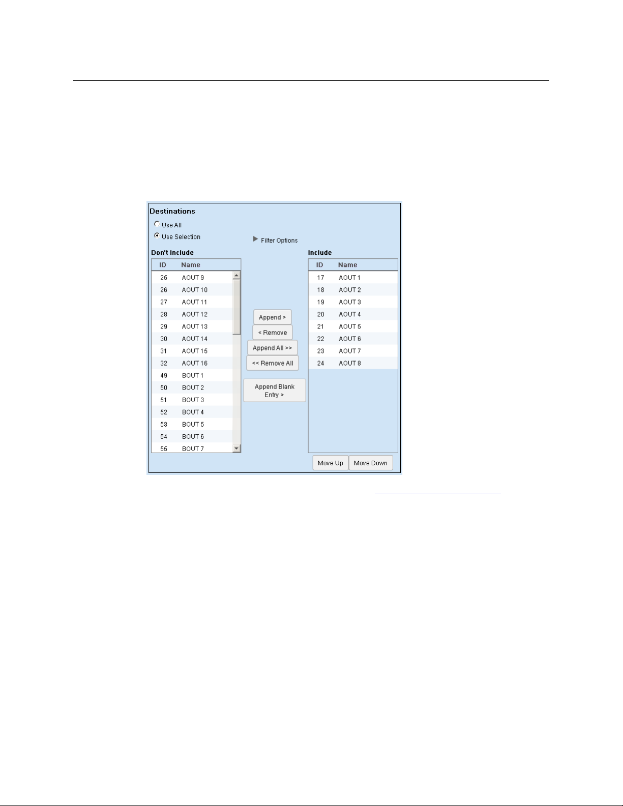
NV9000 Web Suite
User’s Guide
Destination Selection
Choose ‘Use All’ in the ‘Destinations’ region if you want the multi-level display to report all
NV9000 destinations, regardless of what those destinations are. The NV9000 configuration
could change, adding or deleting destinations, and your multi-level page will adjust.
Choose ‘Use Selection’ in the ‘Destinations’ region if you want to specify which destinations the
table is to report. The ‘Destinations’ region expands to allow you to form the destination
selection:
The ‘Use Selection’ fields include filtering options. See Filter Options for Destinations
, following.
The items on the left — under “Don’t Include”— are the destinations that do not appear in the
multi-level page.
The items on the right
— under “Include”— are the destinations that do appear in the multi-level
page.
To move destinations from the “Don’t Include” list to the “Include” list, select one or more entries
in the “Don’t Include” list and click the ‘Append >‘ button or click ‘Append All >>’.
To move destinations from the “Include” list to the “Don’t Include” list, select one or more entries
in the “Include” list and click the ‘< Remove‘ button or click ‘<< Remove All’.
Click ‘Append Blank Entry’ if you want to create a blank line that functions as a separator in your
‘Include’ list. The separator can help you organize the list. The separator also creates a blank row
in the table that is displayed in the page (or pages) of the tab you are editing.
Use the ‘Move Up’ and ‘Move Down’ buttons under the “Include” list to reorder the destinations
(i.e., the table rows). Select one or more destinations in the “Include” list and click ‘Move Up’ or
‘Move ‘Down’ as appropriate to create the ordering you want.
39
Page 50

Options Tab
Configuration Pages
Filter Options for Destinations
Click the triangle for the ‘Filter Options’ to expose the options:
The filter has 3 parts: a destination is included in the lists if it meets all 3 criteria.
If you specify some text in the ‘Search’ field, the filter use a substring matching method: if the
substring you enter as the filter appears in the destination name or its ID, the destination can be
in the lists.
If you choose a level set in the ‘Level Set’ drop-down list, the list is restricted to those destination
devices that are associated with the level set.
If you choose a virtual level in the ‘Virtual Level’ drop-down list, the list is restricted to those
destination devices that include the virtual level in their level set.
The filter ignores the search field if it is blank. It ignores the level set criterion if you choose
‘Display All’. It ignores the virtual level criterion if you choose ‘Display All’ for that.
Copy and Paste Buttons
The ‘Copy’ and ‘Paste’ buttons allow you to transfer page configuration data from one tab to
another tab.
When you click ‘Copy’, all configuration data for that page
lists, all ‘Include’ lists
— are captured in a private buffer ready for pasting elsewhere.
When you click ‘Paste’, presumably in another page, all applicable data are transferred from the
private buffer to the fields of the page. Data in the buffer that do not apply to the page are not
transferred.
Data that were present in the fields that are affected by the ‘Paste’ operation are overwritten.
Fields not applicable to the ‘Paste’ are not affected.
It is not possible to copy the lists from the Web Suite to another application such as Notepad or
Excel.
Data for the configuration of multi-level pages are not applicable in DHP or tieline pages.
Although you use the ‘Copy’ button, the ‘Paste’ button remains disabled in those pages.
Portions of the data from multi-level pages are applicable to primary level pages and matrix
views. These data can be copied.
— all option flags, all ‘Don’t Include’
40
Page 51

NV9000 Web Suite
User’s Guide
Editing a Primary Level Tab
You can control the appearance and content of a primary level crosspoint tab by editing its
parameters in the ‘Pages’ configuration page.
A primary level crosspoint tab has no subtabs.
You can also control the appearance of the tab by indicating your preferences on the sidebar of
when the tab is selected. (Click the blue bar at the left of the Web Suite window to reveal the
sidebar.)
To edit a primary level crosspoint tab, click on a primary level tab in the list of tabs at the left of
the ‘Pages’ configuration page. The primary level tab entry becomes highlighted and the
primary level tab configuration fields of the page appear:
You can specify the name (or title) of the primary level tab.
The primary level page displays destination/source pairs. The source paired with the destina-
tion is the source routed to the destination on the destination’s primary level.
The number of destination/source pairs displayed in the primary level tab can be specified in
the preferences for that tab.
There are several editing options.
Checking the ‘Show Device IDs’ check box causes the NV9000 device ID to appear in the (nonnull) table entries. Device IDs are useful if the NV9000 configuration has duplicate source names.
Device IDs are never duplicated.
The ‘Destinations’ region is for the destinations to be displayed. The page can display data for all
destinations or for selected destinations. If you choose ‘Use Selection’, the region expands to
allow you to form the destination selection. See Destination Selection
You can click the ‘Save’ button at any time to retain your changes.
, following.
41
Page 52

Options Tab
Configuration Pages
Destination Selection
Choose ‘Use All’ in the ‘Destinations’ region if you want the primary level display to report all
NV9000 destinations, regardless of what those destinations are. The NV9000 configuration
could change, adding or deleting destinations, and your primary level page will adjust.
Choose ‘Use Selection’ in the ‘Destinations’ region if you want specify which destinations the
table is to report. The ‘Destinations’ region expands to allow you to form the destination
selection:
42
The ‘Use Selection’ fields include filtering options. See Filter Options for Destinations
The items on the left
— under “Don’t Include”— are the destinations that do not appear in the
, following.
multi-level page.
The items on the right
— under “Include”— are the destinations that do appear in the multi-level
page.
To move destinations from the “Don’t Include” list to the “Include” list, select one or more entries
in the “Don’t Include” list and click the ‘Append >‘ button or click ‘Append All >>’.
To move destinations from the “Include” list to the “Don’t Include” list, select one or more entries
in the “Include” list and click the ‘< Remove‘ button or click ‘<< Remove All’.
Click ‘Append Blank Entry’ if you want to create a blank line that functions as a separator in your
‘Include’ list. The separator can help you organize the list. The separator also creates a blank row
in the table that is displayed in the page (or pages) of the tab you are editing.
Use the ‘Move Up’ and ‘Move Down’ buttons under the “Include” list to reorder the destinations
(i.e., the table rows). Select one or more destinations in the “Include” list and click ‘Move Up’ or
‘Move ‘Down’ as appropriate to create the ordering you want.
Page 53

NV9000 Web Suite
User’s Guide
Filter Options for Destinations
Click the triangle for the ‘Filter Options’ to expose the options:
The filter has 3 parts: a destination is included in the lists if it meets all 3 criteria.
If you specify some text in the ‘Search’ field, the filter use a substring matching method: if the
substring you enter as the filter appears in the destination name or its ID, the destination can be
in the lists.
If you choose a level set in the ‘Level Set’ drop-down list, the list is restricted to those destination
devices that are associated with the level set.
If you choose a virtual level in the ‘Virtual Level’ drop-down list, the list is restricted to those
destination devices that include the virtual level in their level set.
The filter ignores the search field if it is blank. It ignores the level set criterion if you choose
‘Display All’. It ignores the virtual level criterion if you choose ‘Display All’ for that.
Copy and Paste Buttons
The ‘Copy’ and ‘Paste’ buttons allow you to transfer page configuration data from one tab to
another tab.
When you click ‘Copy’, all configuration data for that page
lists, all ‘Include’ lists
— are captured in a private buffer ready for pasting elsewhere.
— all option flags, all ‘Don’t Include’
When you click ‘Paste’, presumably in another page, all applicable data are transferred from the
private buffer to the fields of the page. Data in the buffer that do not apply to the page are not
transferred.
Data that were present in the fields that are affected by the ‘Paste’ operation are overwritten.
Fields not applicable to the ‘Paste’ are not affected.
It is not possible to copy the lists from the Web Suite to another application such as Notepad or
Excel.
Data for the configuration of primary level pages are not applicable in DHP or tieline pages.
Although you use the ‘Copy’ button, the ‘Paste’ button remains disabled in those pages.
Portions of the data from primary level pages are applicable to multi-level pages and matrix
views. These data can be copied.
Editing a Matrix View Tab
You can control the appearance and content of a matrix view tab by editing its parameters in
the ‘Pages’ configuration page.
The matrix view presents a two-dimensional grid. The horizontal axis represents sources in the
router control system. The vertical axis represents destinations. If your router control system has
M sources and N destinations, then the view shows an M × N grid.
43
Page 54

Options Tab
Configuration Pages
The square button at each point in the grid represents a crosspoint in a conceptual matrix.
Clicking a square button performs a take at that crosspoint on the levels you have selected.
The matrix is not the physical crosspoint matrix of any particular router.
A third axis of the grid represents levels. Although you can’t see the third axis, the buttons
show the effect of the third axis. The buttons at each point in the grid show the logical OR of
takes on the levels you have selected for viewing. That is, a button is highlighted if there is a
take on any of the levels at that (cross)point.
A matrix view has no subtabs. But unlike other tabbed pages, it is interactive: you can perform
takes, locks, and protects, set up breakaway and level mapping for takes, and release locks and
protects.
You can also control the appearance of the tab by indicating your preferences in the sidebar
when the tab is selected. (Click the blue bar at the left of the Web Suite window to reveal the
sidebar.)
To edit a matrix view, click on a matrix view tab in the list of tabs at the left of the ‘Pages’ configuration page. The matrix view tab entry becomes highlighted and the matrix view tab
configuration fields of the page appear:
44
You can specify the name (or title) of the matrix view.
There are several editing options. There are two check boxes that control how sources and destinations are displayed. There are 6 radio buttons in 3 regions.
The first region is for the destinations to be displayed in the matrix. The page can display information either for all destinations or for selected destinations. (The matrix view provides a table
Page 55

NV9000 Web Suite
User’s Guide
row for each destination of the matrix.) If you choose ‘Use Selection’ in this region, the region
expands to allow you to form the destination selection. See Destination Selection
, following.
The second region is for the sources to be displayed in the matrix. The page can display information for all sources or for selected sources. (The matrix view provides a table column for each
source of the matrix.) If you choose ‘Use Selection’ in this region, the region expands to allow
you to form the source selection. See Source Selection
, following.
The third region is for the levels that this matrix view can display. The matrix view can display
information for all levels or for selected levels. If you choose ‘Use Selection’ in this region, the
region expands to allow you to form the level selection. See Level Selection
, following.
(Level buttons appear in a section at the top of the matrix view page that the user can enable or
disable. When the section is enabled, the buttons in that section select or deselect levels. The
configuration page lets you determine the levels that the user is allowed to select.)
You can click the ‘Save’ button at any time to retain your changes.
Options
There are two check boxes that control how sources and destinations are displayed:
• Show Destination Device IDs.
• Show Source Device IDs.
These options are unchecked by default.
If you place a check in the ‘Show Destination Device IDs’ check box, destination device IDs are
displayed where destination names are displayed. Otherwise only the names are displayed.
If you place a check in the ‘Show Source Device IDs’ check box, source device IDs are displayed
where source names are displayed. Otherwise only the names are displayed.
45
Page 56

Options Tab
Configuration Pages
Destination Selection
Choose ‘Use All’ in the ‘Destinations’ region if you want the matrix view to use all NV9000 destinations, regardless of what those destinations are. The NV9000 configuration could change
from time to time, adding or removing destinations, and your matrix view will adjust.
Choose ‘Use Selection’ in the ‘Destinations’ region if you want to specify which destinations the
are used in the matrix. The ‘Destinations’ region expands to allow you to form the destination
selection:
46
The ‘Use Selection’ fields include filtering options. See Filter Options for Destinations
The items on the left
— under “Don’t Include”— are the destinations that are not used in the
, following.
matrix view.
The items on the right
— under “Include”— are the destinations that are used in the matrix view.
The filter options control what destinations you can see (or select) in either list of destinations.
The filters do not affect which destinations are actually present in the lists. If you do not use the
filters, all destinations in the list are displayed. See Filter Options for Destinations
, following.
To move destinations from the “Don’t Include” list to the “Include” list, select one or more entries
in the “Don’t Include” list and click the ‘Append >‘ button. (Or click ‘Append All >>’.)
To move destinations from the “Include” list to the “Don’t Include” list, select one or more entries
in the “Include” list and click the ‘< Remove‘ button. (Or click ‘<< Remove All’.)
Click ‘Append Blank Entry’ if you want to create a blank line that functions as a separator in your
‘Include’ list. The separator can help you organize the list. The separator also creates a blank row
in the table that is displayed in the page (or pages) of the tab you are editing.
Use the ‘Move Up’ and ‘Move Down’ buttons under the “Include” list to reorder the destinations
(i.e., the table rows). Select one or more destinations in the “Include” list and click ‘Move Up’ or
‘Move ‘Down’ as appropriate to create the ordering you want.
Page 57

NV9000 Web Suite
User’s Guide
Filter Options for Destinations
Click the dark triangle for the ‘Filter Options’ to expose the filter options:
The filter has 3 parts: a destination is included in the lists if it meets all 3 criteria.
If you specify some text in the ‘Search’ field, the filter use a substring matching method: if the
substring you enter as the filter appears in the destination name or its ID, the destination can be
in the lists.
If you choose a level set in the ‘Level Set’ drop-down list, the list is restricted to those destinations that belong to the specified level set.
If you choose a level in the ‘Virtual Level’ drop-down list, the list is restricted to those destinations that include the level specified.
The filter ignores the search field if it is blank. It ignores the level set criterion if you choose
‘Display All’. It ignores the level criterion if you choose ‘Display All’ for that.
47
Page 58

Options Tab
Configuration Pages
Source Selection
Choose ‘Use All’ in the ‘Sources’ region if you want the matrix view to use all NV9000 sources,
regardless of what those sources are. The NV9000 configuration could change from time to
time, adding or removing sources, and your matrix view will adjust.
Choose ‘Use Selection’ in the ‘Sources’ region if you want to specify which sources the are used
in the matrix. The ‘Sources’ region expands to allow you to form the source selection:
48
The items on the left
— under “Don’t Include”— are the sources that are not used in the matrix
view.
The items on the right
— under “Include”— are the sources that are used in the matrix view.
The filter options control what sources you can see (or select) in either list of sources. The filters
do not affect which sources are actually present in the lists. If you do not use the filters, all
sources in the list are displayed. See Filter Options for Sources
, following.
To move sources from the “Don’t Include” list to the “Include” list, select one or more entries in
the “Don’t Include” list and click the ‘Append >‘ button or click ‘Append All >>’.
To move sources from the “Include” list to the “Don’t Include” list, select one or more entries in
the “Include” list and click the ‘< Remove‘ button or click ‘<< Remove All’.
Click ‘Append Blank Entry’ if you want to create a blank line that functions as a separator in your
‘Include’ list. The separator can help you organize the list. The separator also creates a blank row
in the table that is displayed in the page (or pages) of the tab you are editing.
Use the ‘Move Up’ and ‘Move Down’ buttons under the “Include” list to reorder the sources (i.e.,
the table columns). Select one or more sources in the “Include” list and click ‘Move Up’ or ‘Move
‘Down’ as appropriate to create the ordering you want.
Page 59
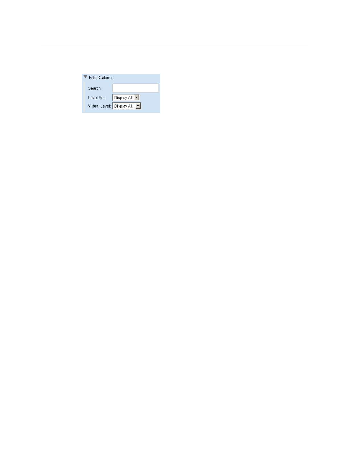
NV9000 Web Suite
User’s Guide
Filter Options for Sources
Click the dark triangle for the ‘Filter Options’ to expose the filter options:
The filter has 3 parts: a source is included in the lists if it meets all 3 criteria.
If you specify some text in the ‘Search’ field, the filter use a substring matching method: if the
substring you enter as the filter appears in the source name or its ID, the source can be in the
lists.
If you choose a level set in the ‘Level Set’ drop-down list, the list is restricted to those sources
that belong to the specified level set.
If you choose a level in the ‘Virtual Level’ drop-down list, the list is restricted to those sources
that include the level specified.
The filter ignores the search field if it is blank. It ignores the level set criterion if you choose
‘Display All’. It ignores the level criterion if you choose ‘Display All’ for that.
49
Page 60

Options Tab
Configuration Pages
Level Selection
Choose ‘Use All’ in the ‘Levels’ region if you want the matrix view to allow the use of all NV9000
levels.
The long list of levels that is normally available is the “universal set” of all “virtual” levels ever
used by NVISION series routers and includes levels that are probably not defined in your
router control system. This list is defined in the virtual levels table of NV9000-SE Utilities. You
can trim the list in NV9000-SE Utilities if you find it cumbersome.
Choose ‘Use Selection’ in the ‘Levels’ region if you want to specify which levels are available to
the user. The ‘Levels’ region expands to allow you to form the level selection:
50
The items on the left
— under “Don’t Include”— are the levels that are not available in the matrix
view.
The items on the right
— under “Include”— are the levels that are available in the matrix view.
The filter options control what levels you can see (or select) in either list of levels. The filters do
not affect which levels are actually present in the lists. If you do not use the filters, all levels in the
list are displayed. See Filter Options for Levels
, following.
To move levels from the “Don’t Include” list to the “Include” list, select one or more entries in the
“Don’t Include” list and click the ‘Append >‘ button or click ‘Append All >>’.
To move levels from the “Include” list to the “Don’t Include” list, select one or more entries in the
“Include” list and click the ‘< Remove‘ button or click ‘<< Remove All’.
Click ‘Append Blank Entry’ if you want to create a blank line that functions as a separator in your
‘Include’ list. The separator can help you organize the list. The separator also creates a blank row
in the table that is displayed in the page (or pages) of the tab you are editing.
Page 61

NV9000 Web Suite
User’s Guide
Use the ‘Move Up’ and ‘Move Down’ buttons under the “Include” list to reorder the levels. Select
one or more levels in the “Include” list and click ‘Move Up’ or ‘Move ‘Down’ as appropriate to
create the ordering you want.
Filter Options for Levels
Click the dark triangle for the ‘Filter Options’ to expose the filter options:
The filter has 2 parts: a level is included in the lists if it meets both criteria.
If you specify some text in the ‘Search’ field, the filter use a substring matching method: if the
substring you enter as the filter appears in the level name or its ID, the level can be in the lists.
If you choose a level set in the ‘Level Set’ drop-down list, the list is restricted to those levels that
belong to the specified level set.
The filter ignores the search field if it is blank. It ignores the level set criterion if you choose
‘Display All’.
Copy and Paste Buttons
The ‘Copy’ and ‘Paste’ buttons allow you to transfer page configuration data from one tab to
another tab.
When you click ‘Copy’, all configuration data for that page
lists, all ‘Include’ lists
— are captured in a private buffer ready for pasting elsewhere.
— all option flags, all ‘Don’t Include’
When you click ‘Paste’, presumably in another page, all applicable data are transferred from the
private buffer to the fields of the page. Data in the buffer that do not apply to the page are not
transferred.
Data that were present in the fields that are affected by the ‘Paste’ operation are overwritten.
Fields not applicable to the ‘Paste’ are not affected.
It is not possible to copy the lists from the Web Suite to another application such as Notepad or
Excel.
Data for the configuration of matrix view pages are not applicable in DHP or tieline pages.
Although you use the ‘Copy’ button, the ‘Paste’ button remains disabled in those pages.
Portions of the data from matrix view pages are applicable to multi-level pages and primary
level pages. These data can be copied.
Users Page
The ‘Users’ page lists all the users authorized to use the Web Suite. (Note that if you are using the
Web Suite, you are logged in as a user.)
Associated with each user is a password (which is optional), a flag indicating whether the user
has admin privilege, a Web Suite configuration, and an NV9000 user name (from the NV9000
system).
The page does not actually list passwords. If you want to change a password, you can click the
‘Change Password’ button for a user. A dialog appears in which you can enter the password.
51
Page 62

Options Tab
Configuration Pages
After you close the dialog, you must remember the password you entered. It is not recoverable if
you forget it.
If a user has the “default” configuration, the configuration entry is colored yellow.
Adding a User to the List
Click the ‘Add New User’ button. A new row appears in the table:
The ‘Username’ field is filled with red and a message appears at the top right: “Username is
empty.”
This message is a prompt for you to click in the ‘Username’ field and enter a user name. When
you do (and follow the entry by pressing ‹enter› or ‹tab›) the field turns green and the prompt
disappears:
The new user has been assigned the default configuration, which is highlighted in yellow. You
can assign a different configuration to the user by selecting a configuration name from the
drop-down list in the user’s ‘Configuration’ field.
You can also assign the user an NV9000 user name in the ‘NVuser’ field.
52
Page 63

NV9000 Web Suite
User’s Guide
The chosen configuration is highlighted in green:
Click ‘Save Users’ to accept any new users you have added. The list refreshes and displays the
users in alphabetical order:
Changing a User’s Password
By default, new users are added with no password required. If you want to assign a password to
a user, click the ‘Change Password’ button for that user. A dialog appears in which you can enter
the new password:
Enter a password, confirm it, and click ‘OK’.
Make a note of the password, or remember it, because you cannot recover the password if you
forget it. (You can always assign a new password however.)
53
Page 64

Options Tab
Configuration Pages
Admin Privilege
Check the ‘Admin’ check box for a user to give that user administrative privilege.
Administrative privilege means that the user can add and remove users, change passwords, and
create and modify Web Suite configurations.
Users without administrative privilege can use the status pages of the configuration they have
been assigned. They cannot redefine their configurations.
User IDs
NV9000-SE Utilities allows persons configuring the router control system to define user IDs. User
IDs are normally associated with control panels.
In NV9000-SE Utilities, user IDs are alphanumeric strings that usually form readable names.
The Web Suite allows you to associate any user name defined in the NV9000 router control
system with a user in the list. There are drop-down lists in the NVUSER column from which you
can choose a user name. The NV9000 user name and its database ID are subsequently used to
indicate which user has issued a lock or a protect on destinations in the router control system.
It is advisable to have all NV9000 user names defined (in NV9000-SE Utilities) and assigned
(in the Web Suite) at the earliest opportunity. Users who perform locks and protects under
one NV9000 user name cannot release those locks and protects if they change to a different
NV9000 user name.
Saving the User List
Click ‘Save Users’ to save the list and click ‘Yes’ in the confirmation dialog that appears.
If you made a data entry mistake before you save, you can discard the mistake(s) by using your
browser’s refresh button to refresh the ‘Users’ page. Doing so reloads the saved user list from the
NV9000 database. (You will be warned if you about to lose unsaved data.)
Removing a User from the List
You cannot remove a new user from the list until you have saved the user list. New users and
new data are characterized by green-highlighted fields in the list.
To remove a user or users from the list, place a check mark in the ‘Delete’ check box for the
user(s). The row(s) for those users(s) are greyed out:
54
Then click ‘Save Users’ and click ‘Yes’ in the confirmation dialog that appears. The Web Suite
displays the updated user list
Page 65

Log Pages
NV9000 Web Suite
User’s Guide
The Logs subtab provides 3 or 4 status pages — 4 when instrumentation mode is enabled:
Disabled Enabled
Server Log Server Log
Client Log Client Log
System Status System Status
Data Store
The ‘Data Store’ are for Miranda engineers and technicians only.
Instrumentation mode is a checkbox option under the ‘Servers’ page under the ‘Configura-
tion’ subtab.
System Status
The ‘System Status’ page presents statistics and data about the Web Suite:
These are the statistics:
• Heap memory used by the NV9000 Web Suite, in mebibytes. (A mebibyte is 2
• Current active thread count.
• Total page load time (in milliseconds).
• Total network latency (in milliseconds).
20
bytes.)
55
Page 66

Options Tab
Log Pages
Client Log Page
This is the ‘Client Log’ page:
This page usually contains a great amount of event history regarding the Web Suite client.
Green text is used for debugging or informative messages.
Red text is used for warnings or error messages.
Server Log Page
This is the ‘Server Log’ page:
56
This page usually contains a great amount of event history regarding the NV9000 Web Suite
server.
You might have to use this information to diagnose a system failure or a network problem.
Page 67

NV9000 Web Suite
least severe
most severe
User’s Guide
Hide Menu
You can hide the menu by clicking the text ‘Hide Menu’. This is the page without the menu:
(The text changes to ‘Show Menu’.)
Place a check mark in the ‘Auto Refresh’ check box if you want the page to refresh its display at
every reported event. If the check box is not checked, the NV9000 Web Suite refreshes the page
every time you switch to the page (or click your browser’s refresh icon).
Reporting Level
You can choose the level of reporting in this log. (Other users can choose a different reporting
level.) To choose a reporting level, select a level from the drop-down list:
The levels are listed in order of severity.
You can also choose one of the 5 display filters directly:
DEBUG-4 DEBUG INFO WARN ERROR
in the text below the level drop-down menu.
57
Page 68

Options Tab
Log Pages
Data Store Page
Do not use this page. It is for Web Suite developers.
58
Page 69

Summary
DHP Tab
Chapter 3 provides information and instructions regarding the Web Suite’s DHP tab.
Topics
Summary . . . . . . . . . . . . . . . . . . . . . . . . . . . . . . . . . . . . . . . . . . . . . . . . . . . . . . . . . . . . . . . . . . . . . . . . . . . . . . . . 59
Disembedder Page . . . . . . . . . . . . . . . . . . . . . . . . . . . . . . . . . . . . . . . . . . . . . . . . . . . . . . . . . . . . . . . . . . . . . . . 61
Embedder Page . . . . . . . . . . . . . . . . . . . . . . . . . . . . . . . . . . . . . . . . . . . . . . . . . . . . . . . . . . . . . . . . . . . . . . . . . . 63
Reentry Page . . . . . . . . . . . . . . . . . . . . . . . . . . . . . . . . . . . . . . . . . . . . . . . . . . . . . . . . . . . . . . . . . . . . . . . . . . . . . 65
Drawing Page . . . . . . . . . . . . . . . . . . . . . . . . . . . . . . . . . . . . . . . . . . . . . . . . . . . . . . . . . . . . . . . . . . . . . . . . . . . . 67
When you click on the DHP tab, the DHP subtabs and their pages appear. By default, there are 4
pages:
Disembedder Embedder
Reentry Drawing
However, you can configure the DHP tab to have a subset of these pages. Use the ‘Options’ tab
and its ‘Configuration > Pages’ page to do so.
The four DHP pages show information about the current state of the DHP core of a single
NV8500 series router (NV8140, NV8144, NV8280, NV8576, or NV8576-Plus).
DHP is any option that applies only to an NV8500 series router. Your system might not have
DHP.
Three of its pages present tables of DHP core data. The fourth page presents the data as a
drawing. The table data present all the signal detail of the DHP core. The drawing page is a
diagrammatic view of the current core.
The following sections describe the pages.
The examples shown in this section refer to a demonstration NV9000 system. The configuration
data for that system are listed in the Sample NV9000 Configuration
Caution: the DHP pages are status pages. You cannot control the DHP service, or stop it, or
restart it, from the NV9000 Web Suite.
Because of the way DHP is defined, it can communicate with only one DHP client. The client
can be a PC running the NV9000 Web Suite or it can be an instance of DHP-D.
If DHP-D is running, no PC client will obtain correct DHP information and any PC applications
attempting to do so might display incorrect data. Further, PC clients are services that run in
the background on your PCs whether the user has a web browser open or not. Only one
such service may be started at a given time and DHP-D cannot also be running. Otherwise,
the DHP tab of the Web Suite will not function correctly or will not function at all.
on page 70.
1
1. DHP-D is Miranda diagnostic software.
59
Page 70

DHP Tab
Std Out for Disembedder 29
INA 045
Disembedder 29
Embedder 19
Legend
Internal Route
Core Cable for Disembedder
Audio Channels
INA 410
Std Out for Disembedder 28
Disembedder 28
OUTA 455
Std In for
Embedder 19
Core Cable for Embedder
Summary
Configuration Options
The 4 DHP pages can be individually enabled or disabled. The 4 DHP pages can be configured:
• To show all or selected disembedders. For selected disembedders, a name/ID filter can apply.
• To show all or selected embedders. For selected embedders, a name/ID filter can apply.
• To show port numbers next to port names.
For information about configuring DHP pages, see Editing a DHP Tab
on page 28.
Example
Figure 3-1 shows an DHP routing example for the 4 tabbed pages described in the following
sections:
60
Fig. 3-1: Sample DHP Route
Standard source INA 410 is taken to standard destination OUTA 455 on all levels but two. The
remaining two levels (levels 3 and 4) are take from standard source INA 045. Except for the
breakaway involved, DHP would not be required. Because a breakaway occurred, the DHP software routed INA 410 through DHP disembedder port 28 and INA 045 through DHP
disembedder port 29. The audio from these two ports are recombined in DHP embedder port
19 and forwarded, with the original video from INA 410 to standard output OUTA 455.
Page 71

Disembedder Page
The ‘Disembedder’ page shows details of the DHP core’s disembedders:
NV9000 Web Suite
User’s Guide
Fig. 3-2: Disembedder Page
The page displays a table of all the disembedder ports in the DHP core, one row for each port.
The disembedder ports are identified in column 1. If a disembedder is not in use, its table row is
empty (except for the label in column 1 and port number in column 3).
Fields for unused disembedders are greyed out.
Entries in the column labeled ‘SDI’ show the name of the standard input port connected to the
disembedder port. It represents the video signal. If there is no name or the name cannot be
determined the entry shows “********”.
An entry in the column labeled ‘Disembedder Port’ identifies the standard output that is
connected to (i.e., feeds) the disembedder. That output port is part of the DHP core.
The entries in the columns labeled ‘Feeding 1’, ‘Feeding 2’, and so on, show either embedders or
output ports that are fed by the disembedder port. The table can have from 0 to 10 “Feeding”
columns.
Table Ordering
By clicking the header of any table column you can cause the table to be reordered according
the entries in that column. Click the header once and the table is put in ascending order for that
column. Click the header again to put the table in descending order of that column. An arrow
(up or down) appears in the column header to indicate that the table is ordered according to
that column.
To revert to the default table ordering, click the page refresh icon of your browser.
61
Page 72

DHP Tab
Disembedder Page
Preferences
The ‘Disembedder’ page has several user-selectable preferences, available in the sidebar:
These are the preferences:
• Filtering enabled
Checking this option places a search filter on the ‘Disembedder’ page:
You can place text in this field to limit the number of rows that are displayed. Only those
rows in which the search text appears
— in any column — are displayed.
• Automatically move unused disembedders to bottom
It might be more convenient for you to display all the disembedders that are in use in the
upper rows of the table. That way, you can minimize scrolling and confusion as you navigate
to view different disembedders that are in use.
• Display columns
These 4 items let you select exactly what is displayed for each disembedder. The 3 check
boxes refer to the first 3 columns of the table.
The number of destination columns (i.e., ‘Feeding’ columns) defaults to 8 but you can
increase or decrease the number of these columns. It makes sense to decrease the number
of the ‘Feeding’ columns because they often contain no information.
62
Page 73

Embedder Page
The ‘Embedder’ page shows details of the DHP core’s embedders. The page displays a table of all
the embedder ports in the DHP core, one row for each port. The embedder ports are identified
in column 1. If an embedder is not in use, its table row is empty (except for column 1).
This view shows the left side of the page:
NV9000 Web Suite
User’s Guide
Fig. 3-3: Embedder Page, Left Por tion
Unused embedders are greyed out. Here, only one embedder is in use.
Entries in the column labeled ‘SDI’ show the name of the standard input port connected to the
disembedder port that feeds the video to the embedder port.
The entries in the columns labeled ‘Audio 1’, ‘Audio 2’, and so on, show the audio channels that
are fed to the embedder port. The audio signals can come from any disembedder in the DHP
core, from a MADI card, or from any hybrid card not in the DHP core.
The audio channels are identified by their associated video port names. Bold purple text indicates that the audio channel is either a breakaway channel or the result of level mapping.
Table Ordering
By clicking the header of any table column you can cause the table to be reordered according
the entries in that column. Click the header once and the table is put in ascending order for that
column. Click the header again to put the table in descending order of that column. An arrow
(up or down) appears in the column header to indicate that the table is ordered according to
that column.
To revert to the default table ordering, click the page refresh icon of your browser.
63
Page 74

DHP Tab
Embedder Page
Preferences
The ‘Embedder’ page has several user-selectable preferences, available in the sidebar:
64
These are the preferences:
• Filtering enabled
Checking this option places a search filter on the ‘Embedder’ page:
You can place text in this field to limit the number of rows that are displayed. Only those
rows in which the search text appears
— in any column — are displayed.
• Automatically move unused embedders to bottom
It might be more convenient for you to display all the embedders that are in use in the upper
rows of the table. That way, you can minimize scrolling and confusion as you navigate to
view different embedders that are in use.
Page 75
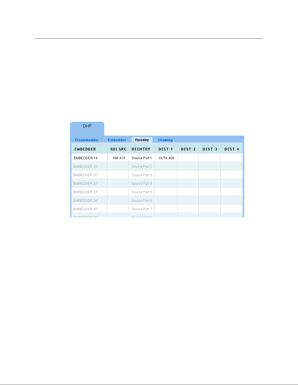
• Display columns
Reentry Page
The ‘Reentry’ page shows which standard video input and standard video outputs are
connected to each embedder port:
NV9000 Web Suite
User’s Guide
These 18 items let you select exactly what is displayed for each embedder. The check boxes
refer to the columns of the table.
The default shows all 16 embedded audio channels. Some systems might have fewer
embedded channels. Disabling the display of unused channels can make it easier to use the
embedder page.
Fig. 3-4: DHP Reentry Page
The page displays a table of all the embedder ports in the DHP core, one row for each port. The
embedder ports are identified in column 1. If an embedder is not in use, its table row is empty
(except for column 1 and column 3).
The ‘Reentry’ column of this page identifies the standard input port that is connected to the
embedder output port. That input port is part of the DHP core.
The ‘Dest’ columns identify the standard outputs fed by the embedder
input port.
The ‘SDI SRC’ column identifies the video-level input to the embedder.
Unused embedders are greyed out. In the illustration, only one embedder is in use.
— through the standard
Table Ordering
By clicking the header of any table column you can cause the table to be reordered according
the entries in that column. Click the header once and the table is put in ascending order for that
column. Click the header again to put the table in descending order of that column. An arrow
(up or down) appears in the column header to indicate that the table is ordered according to
that column.
To revert to the default table ordering, click the page refresh icon of your browser.
65
Page 76

DHP Tab
Reentry Page
Preferences
The ‘Reentry’ page has several user-selectable preferences, available in the sidebar:
These are the preferences:
• Filtering enabled
Checking this option places a search filter on the ‘Reentry’ page:
You can place text in this field to limit the number of rows that are displayed. Only those
rows in which the search text appears
— in any column — are displayed.
• Automatically move unused embedders to bottom
It might be more convenient for you to display all the embedders that are in use in the upper
rows of the table. That way, you can minimize scrolling and confusion as you navigate to
view different embedders that are in use.
• Display columns
These 4 items let you select exactly what is displayed for each embedder. The 3 check boxes
refer to the first 3 columns of the table.
The number of destination columns defaults to 8 but you can increase or decrease the number of these columns. It makes sense to reduce the number of the ‘Dest’ columns because
they often contain no information.
66
Page 77

Drawing Page
The ‘DHP Drawing’ page gives you a graphic or “schematic” view of the DHP core. This is a
sample:
NV9000 Web Suite
User’s Guide
Fig. 3-5: Drawing Page
This sample shows the DHP route of the example used throughout this chapter. To reiterate:
Standard source INA 410 is taken to standard destination OUTA 455 on all levels but two. The
remaining two levels (levels 3 and 4) are take from standard source INA 045. Except for the
breakaway involved, DHP would not be required. Because a breakaway occurred, the DHP
software routed INA 410 through DHP disembedder port 28 and INA 045 through DHP disembedder port 29. The audio from these two ports are recombined in DHP embedder port
19 and forwarded, with the original video from INA 410 to standard output OUTA 455.
Central to the page is a rectangle representing the router connected to the system controller’s
DHP service.
The top half of the rectangle represents standard input and output ports, some of which are part
of the DHP core. (The ports belonging to the core are labeled with their associated disembedder
or embedder port. See the Sample NV9000 Configuration
on page 70.
67
Page 78

DHP Tab
Drawing Page
The bottom half of the rectangle represents hybrid inputs and outputs, some of which might not
be part of the DHP core. Hybrid I/O includes disembedder ports, embedder ports, and MADI
input or output connections.
Signal Paths
Dashed lines represent standard inputs and outputs connected to the core. For instance, in the
illustration, INA 045 is a standard input and OUTA 455 is a standard output. See the Sample
NV9000 Configuration on page 70.
Solid lines represent paths within the DHP core. Single black lines represent video with or
without embedded audio. Blue 3-line groups represent audio disembedding and re-embedding. The 3-line groups represent any number of audio channels (from 1 to 16), not just 3.
Short red lines represent connections to the disembedders and embedders of the core.
Usage
At the left side of the page are two regions:
• Radio buttons.
The 4 radio buttons allow you to select what appears in the check boxes in the second
region. For instance, if you select the ‘Embedders’ radio button, a list of the embedders
appears in the second region.
• Check boxes.
When you check a box in this region, the drawing shows all DHP elements that relate to what
you have checked. For example, Figure 3-5, on page 67, has embedder 19 checked. The
drawing shows the disembedders, standard inputs, and standard outputs that connect to
embedder 19.
Depending on which radio button you chose, the check box list will include special check
boxes: ‘All unused disembedders’, ‘All unused embedders’, or ‘All other DHP resources’. Checking one of these boxes will result in the display of the named items.
Also at the left side of the page are two buttons:
• Select All.
This is a shortcut that checks all the check boxes in the list and causes the drawing to show
all the items corresponding to all the check boxes.
• Clear Selection.
This shortcut clears all the check boxes in the list. The result is that the drawing shows nothing (except the rectangle representing the router).
68
Page 79

NV9000 Web Suite
User’s Guide
When you select many or all items in the check box list, the drawing shows many connections:
This kind of view obscures individual connection details. We recommend that you view one or
two core connections at a time.
Preferences
The ‘Drawing’ page has several user-selectable preferences, available in the sidebar:
69
Page 80

DHP Tab
Sample NV9000 Configuration
These are the preferences:
• Filtering enabled
Checking this option places a search filter on the ‘Drawing’ page:
You can place text in this field to limit the number of items that are displayed. Only those
items in which the search text appears are displayed.
• Hide check boxes for unused resources.
It might be more convenient for you if your drawing page does not have check boxes to
show unused disembedders, embedders, and so on.
Sample NV9000 Configuration
These are the data of the NV9000 configuration from which the DHP example was taken.
Non-Core Ports
These are the ports — not in the DHP core — that are used in the examples. These were configured in NV9000-SE Utilities.
Input
These are all standard inputs, each having video and 16 audio channels.
Device HD Port Audio Por ts
INA 37 37 577–592
through
INA 576 576 9201–9216
There are also MADI ports 1–64 from input card 1.
Output
These are all standard outputs, each having video and 16 audio channels\.
Device HD Port Audio Por ts
OUTA 37 37 577–592
through
OUTA 576 576 9201–9216
There are also MADI ports 1–64 on output card 1.
70
Page 81

NV9000 Web Suite
User’s Guide
DHP Core Ports
These are the ports of the DHP core, as configured in the HybridPorts_xxxx file (one of the
two DHP configuration files).
Re-embedders tied to Standard Inputs
Embedder Port Standard Input Port
19 1
20 2
21 3
22 4
23 5
24 6
25 7
26 8
28 10
29 11
30 12
31 13
32 14
33 15
34 16
35 17
(These embedder outputs are all on output card 2. Note that the ports that would be numbered
27 and 36 do not exist.)
Disembedders tied to Standard Outputs
Disembedder Port Standard Output Port
28 1
29 2
30 3
31 4
32 5
33 6
34 7
71
Page 82

DHP Tab
Sample NV9000 Configuration
72
Page 83

Summary
Tielines Tab
Chapter 4 provides information and instructions regarding the Web Suite’s ‘Tielines’ tab.
Topics
Summary . . . . . . . . . . . . . . . . . . . . . . . . . . . . . . . . . . . . . . . . . . . . . . . . . . . . . . . . . . . . . . . . . . . . . . . . . . . . . . . . 73
Background Information . . . . . . . . . . . . . . . . . . . . . . . . . . . . . . . . . . . . . . . . . . . . . . . . . . . . . . . . . . . . . . . . . 74
Tieline Uses Page . . . . . . . . . . . . . . . . . . . . . . . . . . . . . . . . . . . . . . . . . . . . . . . . . . . . . . . . . . . . . . . . . . . . . . . . . 76
Tieline Destinations Page . . . . . . . . . . . . . . . . . . . . . . . . . . . . . . . . . . . . . . . . . . . . . . . . . . . . . . . . . . . . . . . . . 80
Tieline Drawing Page . . . . . . . . . . . . . . . . . . . . . . . . . . . . . . . . . . . . . . . . . . . . . . . . . . . . . . . . . . . . . . . . . . . . . 83
When you click on the tielines tab, the tieline subtabs and their pages appear. By default, there
are 3 pages:
Tieline Uses Tieline Destinations Tieline Drawing
However, you can configure the tieline tab to have a subset of these pages. Use the ‘Options’ tab
and its ‘Configuration > Pages’ page to do so.
The three tieline pages show information about the current state of tielines in the entire NV9000
system controlled by the system controller you are monitoring with the Web Suite. The system
can include several routers.
Two tieline pages present tables of tieline data. The third page presents the data as a drawing.
The drawing page is a “schematic” view of the routers and tielines.
The following sections describe the pages.
The examples shown in this section refer to a demonstration NV9000 system. The configuration
data for that system are listed in Sample NV9000 Data
on page 75.
Note: tielines are a purchase option of NV9000 systems. Your system might not actually
support tielines. If it does not, the Web Suite will not show any tieline data.
73
Page 84

Tielines Tab
Output
Router 1 Router 2
Input
Tieline
Output
Router 1 Router 2
Input
Router n
Input
Output
Output
Router 1
Router 2
Input
Router 4
Input
Output
Router 3
Input
Output
Output
Input
Background Information
Background Information
A tieline (or a “simple” tieline) is defined as a connection from an output of an upstream router to
the input of a downstream router:
Sources and destinations that are connected using tielines and that comprise multiple levels
(perhaps on different routers) must have a tieline connection on each of the applicable levels.
A multi-hop tieline is a set of simple tielines between multiple routers, perhaps at remote
geographical locations.
A tieline route is one taken from a source on an upstream router to a destination on a downstream router.
The NV9000 system uses tielines as a pool of resources. When the NV9000 needs to use a tieline
to perform a route, it determines all the tielines necessary to make the route. If the pool of
tielines is depleted, of course, it cannot make the route.
Fig. 4-1: Pooled Tielines
In Figure 4-1, there are no tieline paths from router 2 to router 3. If the NV9000 system cannot
find a tieline path for a route, it cannot make the route.
The tieline pages of the Web Suite show (1) the routes used by the tielines in your system and (2)
the tielines that remain unused. (The latter are shown greyed out.)
74
Page 85

NV9000 Web Suite
141
RTR A RTR B RTR C
141 141 141
142 142 142 142
143 143 143 143
AIN
[116 ]
COUT
[116 ]
144 144 144 144
(HD) (SD) (HD)
AB1
AB2
AB3
AB4
BC1
BC2
BC3
BC4
BOUT
[116 ]
CIN
[116 ]
AOUT
[116 ]
BIN
[116 ]
Tielines
(Down Conversion)
Tielines
(Up Conversion)
COUT1
COUT3
BOUT2
BC1
AIN1
AIN2
BIN3
AB1
BC2
AB2
RTR A RTR B RTR C
User’s Guide
The demonstration system used in the examples in this chapter has a small set of tielines that
allow multi-hop routes.
Sample NV9000 Data
The (simple) demonstration setup for tielines has 3 routers, A, B, and C.
The routers are identical in size, each having 16 general inputs and outputs, except that router B
routes SD, not HD. Tielines that perform up- and down-conversion are required between A and
B and between B and C.
Thus, between A and B, there are 4 tielines, AB1 through AB4. Between B and C, there are 4
tielines, BC1 through BC4.
A route from router A to router C (through router B) is a 2-hop route.
The tielines form pool of resources from which the router control system can draw when it
wants to perform routers from A to B, from B to C, or from A to C.
(Routes from C to A, B to A, and C to B are not defined in this demonstration system.)
Sample Tieline Routes
Using the sample system, three tieline routes were made, one from A to C, one from A to B, and
one from B to C:
Fig. 4-2: Sample Tieline Routes
The route from AIN1 to COUT1 is considered “multi-hop.”
These routes are depicted in the following sections.
75
Page 86

Tielines Tab
COUT1
AIN1
BC2
AB2
RTR A RTR B RTR C
Tieline Uses Page
Tieline Uses Page
The ‘Tieline Uses’ page shows simple tielines that are used for routes:
Fig. 4-3: Tieline Uses Page
Tielines that are not in use are greyed out.
The page shown in Figure 4-3 illustrates the three tielines of Figure 4-2.
Table Ordering
By clicking the header of any table column you can cause the table to be reordered according
the entries in that column. Click the header once and the table is put in ascending order for that
column. Click the header again to put the table in descending order of that column. An arrow
(up or down) appears in the column header to indicate that the table is ordered according to
that column.
To revert to the default table ordering, click the page refresh icon of your browser.
Interpretation
The first two rows of the table represent the multi-hop tieline from AIN1 to COUT1:
Each row is one hop.
In a multi-hop tieline, some of the sources and destinations are tieline ports, indicated by the
names of the tielines. In the first row, for example, the source for the second hop is the tieline
port AB2.
76
Page 87

The third row represents a simple tieline route from AIN2 to BOUT2:
BOUT2
AIN2
AB1
RTR A RTR B
COUT3
BC1
BIN3
RTR B RTR C
The fourth row represents a simple tieline route from BIN3 to COUT3:
NV9000 Web Suite
User’s Guide
The other rows in the table represent tielines that are not used.
(The tieline drawing illustrated in Figure 4-5 also shows these routes.)
Preferences
The ‘Uses’ page has several user-selectable preferences, available in the sidebar:
77
Page 88

Tielines Tab
Clicked this row
Clicked this row
Tieline Uses Page
These are the preferences:
• Filtering enabled
Checking this option places a name filter and a group filter on the ‘Uses’ page:
You can place text in the ‘Search’ field to limit the number of rows that are displayed. Only
those rows in which the search text appears
— in any column — are displayed.
You can select a tieline group in the ‘Group’ drop-down menu to restrict the tielines displayed only to those belonging to that group.
• Automatically move unused tielines to bottom
It might be more convenient for you to display all the tielines that are in use in the upper
rows of the table. That way, you can minimize scrolling and confusion as you navigate to
view different tielines that are in use.
• Highlighting enabled
Checking this option allows you to highlight table rows belonging to a tieline (in green, yellow, purple, or blue):
This is particularly useful to show the rows of a multi-hop tieline, which might be difficult to
locate without this aid.
(In a multi-hop tieline, the row you click is the one that is highlighted green. Tieline hops
upstream of that one are highlighted in yellow and tieline hops that are downstream of that
one are highlighted in purple. Here is the same (multi-hop) tieline highlighted in yellow and
green:
If a tieline goes to multiple destinations, the additional destinations are highlighted in blue.
(It is a blue-violet color and distinguishable from the blue tones of the Web Suite page.)
78
Page 89

NV9000 Web Suite
User’s Guide
• Display use information
Checking this option causes the page to display the number of tielines that are in use and
the number that are available:
• Releasing tielines enabled
Checking this option causes the page to display a ‘Release Tieline’ button:
When the ‘Release Tielines’ button is enabled, you can release tielines. To do so, select a
tieline path in the uses table and click the button. the software displays a warning:
Click ‘Yes’ to proceed or ‘No’ to cancel the release.
• Display columns
These 11 check boxes let you select exactly what is displayed for each tieline row (or hop).
Each check box corresponds to a column in the ‘Tieline Uses’ table. (Figure 4-3 shows just a
few of these columns.)
These are the meanings of the optional columns of the table:
• ‘Dst’ — the destination of this simple tieline.
• ‘Dst Level’ — the physical level on which the tieline route is made, in the downstream
router.
• ‘Source’ — the source of this simple tieline.
• ‘Src Level’ — the physical level on which the tieline route is made, in the upstream router.
• ‘Tieline’ — the name of the tieline.
• ‘Description’ — a description of the tieline that was defined at the time the tieline was
defined in NV9000-SE Utilities.
• ‘User’ — the user name assigned to the control panel at which the route was made.
79
Page 90

Tielines Tab
Tieline Destinations Page
• ‘Duration’ — how long the tieline has been in effect, in days, hours, minutes, and seconds.
• ‘Start Time’— the start time and date of the route that used the tielines.
• ‘Group’— the tieline group to which the tieline belongs. (Your system might not have
tieline groups, in which case you might leave this option unchecked.)
• ‘IP’ — either 0.0.0.0 or the loopback address of the system controller.
Numbers in parentheses in the source and destination fields are input or output port numbers.
(The presence of these numbers is a page configuration option.)
The numbers in parentheses in the tieline and physical level fields are the NV9000 database IDs
for the entries in those fields. (The presence of these numbers is a page configuration option.)
Tieline Destinations Page
The ‘Tieline Destinations’ page shows tielines that are used for routes:
80
Fig. 4-4: Tieline Destinations Page
Tielines that are not in use are greyed out.
The page shown in Figure 4-4 illustrates one 2-hop tieline (from AIN1 to COUT1) and two singlehop tielines (from AIN2 to BIN2 and from BIN3 to CIN3).
The ‘Tieline Destinations’ page shows the same tielines as the ‘Tieline Uses’ page.
Here, however, the page shows multiple destinations (if there are any) for each of the tielines.
The tieline service in the NV9000 can connect one tieline source to multiple tieline destinations.
This page shows those destinations.
If the tieline has more destinations than the number of ‘Dest’ columns in the table, then the
additional destinations wrap around in the same row as the first set of destinations. (The height
of the row increases.)
The page shows the originating source in the ‘Source’ column. In Figure 4-4, the rows for the “C”
tielines show multi-hop routes. The page, in general, shows a mix of simple tieline routes and
multi-hop routes.
Page 91

NV9000 Web Suite
User’s Guide
Table Ordering
By clicking the header of any table column you can cause the table to be reordered according
the entries in that column. Click the header once and the table is put in ascending order for that
column. Click the header again to put the table in descending order of that column. An arrow
(up or down) appears in the column header to indicate that the table is ordered according to
that column.
To revert to the default table ordering, click the page refresh icon of your browser.
Interpretation
Figure 4-4 shows the tieline example of Figure 4-2.
The first two rows belong to the multi-hop tieline from AIN1 to COUT1.
The third row shows the single-hop tieline from AIN2 to BOUT2.
The fourth row shows the single-hop tieline from BIN3 to COUT3.
The rows identify the most upstream source and the most downstream destination of the tieline
route. Each row gives the name of a tieline “hop” for the route.
Preferences
The ‘Destinations’ page has several user-selectable preferences, available in the sidebar:
These are the preferences:
• Filtering enabled
Checking this option places a name filter and a group filter on the ‘Uses’ page:
You can place text in the ‘Search’ field to limit the number of rows that are displayed. Only
those rows in which the search text appears
— in any column — are displayed.
81
Page 92

Tielines Tab
Tieline Destinations Page
• Automatically move unused tielines to bottom
• Display use information
• Releasing tielines enabled
You can select a tieline group in the ‘Group’ drop-down menu to restrict the tielines displayed only to those belonging to that group.
It might be more convenient for you to display all the tielines that are in use in the upper
rows of the table. That way, you can minimize scrolling and confusion as you navigate to
view different tielines that are in use.
Checking this option causes the page to display the number of tielines that are in use and
the number that are available:
Checking this option causes the page to display a ‘Release Tieline’ button:
When the ‘Release Tielines’ button is enabled, you can release tielines. To do so, select a
tieline path in the uses table and click the button. the software displays a warning:
Click ‘Yes’ to proceed or ‘No’ to cancel the release.
• Display columns
These 3 items let you select exactly what is displayed for each tieline. The 2 check boxes refer
to the first 2 columns of the table.
The number of destination columns defaults to 8 but you can increase or decrease the number of these columns. It makes sense to reduce the number of the ‘Dest’ columns because
they often contain no information.
Numbers in parentheses in the source and destination fields are input or output port numbers.
(The presence of these numbers is a page configuration option.)
82
Page 93

The numbers in parentheses in the tieline field are the NV9000 database IDs for the entries in
those fields. (The presence of these numbers is a page configuration option.)
Tieline Drawing Page
The ‘Tieline Drawing’ page presents a graphical view of tielines used for routes:
NV9000 Web Suite
User’s Guide
Fig. 4-5: Tieline Drawing Page
At the left side of the page are controls (radio buttons and check boxes) that let you select for
display only the items you want to see.
The radio buttons select the category of items that you can choose in the section of check boxes
below the radio buttons. If you click the ‘Destinations’ radio button, the check boxes correspond
to destinations related to the tielines.
By checking and unchecking the items (such as destinations) in the check box list, you can
control which tielines are shown in the drawing.
In Figure 4-5 above, the ‘Tielines’ radio button was chosen. Therefore, the names of tielines
appear in the checkbox list. In this case, all check boxes are selected. The drawing includes
unused tielines. (To include or exclude unused tielines is a a tieline preference that you can set.
See Preferences
There are two buttons below the check box list: ‘Select All’ and ‘Clear Selection’. These are shortcuts that allow you to select all check boxes in the list or unselect all check boxes in the list.
, following)
Interpretation
Figure 4-5 shows a drawing representing the tieline example of Figure 4-2.
Each rectangle represents a physical level of a router. The rectangles are labeled with the level
name (which is defined in NV9000-SE Utilities). In many cases, a router has a single physical level,
so in those cases, the rectangle represents the router as well.
83
Page 94

Tielines Tab
Tieline Drawing Page
Dark lines that connect sources (at the left side of the rectangles) to destinations (at the right
side of the rectangles) are tieline routes. Black lines are connections within the router; dark blue
lines are connections between routers. The dark blue lines are the actual tielines.
Light gray lines represent unused tielines.
In Figure 4-5, you can see the tielines of the example: one 2-hop tieline running from AIN1 to
COUT1 and two single-hop tielines (AIN2 to BOUT2 and BIN3 to COUT3).
If the tieline configuration page enables it, the drawings page will show port numbers next to
the port names in the drawing. See Editing a Tieline Tab
on page 33.
Preferences
The ‘Drawings’ page has several user-selectable preferences, available in the sidebar:
These are the preferences:
• Filtering enabled
Checking this option places a name filter on the ‘Drawing’ page:
You can place text in the ‘Search’ field to limit the number of items that are displayed. Only
those items in which the search text appears are displayed.
• Hide check boxes for unused tielines
If you wish to disregard unused tielines, checking this option will prevent their being displayed in the check box list or in the drawing.
• Display use information
Checking this option causes the page to display the number of tielines that are in use and
the number that are available:
84
Page 95

Summary
Multi-Level Tab
Chapter 5 provides information and instructions regarding the NV9000 Web Suite’s ‘Multi-Level’
tab.
Topics
Summary . . . . . . . . . . . . . . . . . . . . . . . . . . . . . . . . . . . . . . . . . . . . . . . . . . . . . . . . . . . . . . . . . . . . . . . . . . . . . . . . 85
Locks and Protects . . . . . . . . . . . . . . . . . . . . . . . . . . . . . . . . . . . . . . . . . . . . . . . . . . . . . . . . . . . . . . . . . . . . . . . . 87
The ‘Multi-Level’ tab presents a list of destinations and for each destination, the sources that
feed the destinations on one or more (virtual) levels.
Thus, each field to the right of the destination column is a source on the level indicated by the
column header. If there is no source on a particular level, the field displays a dash.
Sources from a tieline are displayed in italics.
By default, the ‘Multi-Level’ page displays all destinations and all virtual levels defined in the
system controller’s configuration. The Web Suite’s configuration page, however, lets you specify
exactly which destinations and exactly which virtual levels are displayed in the list.
85
Page 96

Multi-Level Tab
Table Ordering
You can create more than one ‘Multi-Level’ tab. Several ‘Multi-Level’ tabs can display different
views of different data.
See Editing a Multi-Level Crosspoint Tab
pages and specifying the levels that appear in the page.
Table Ordering
By clicking the header of any table column you can cause the table to be reordered according
the entries in that column. Click the header once and the table is put in ascending order for that
column. Click the header again to put the table in descending order of that column. An arrow
(up or down) appears in the column header to indicate that the table is ordered according to
that column.
To revert to the default table ordering, click the page refresh icon of your browser.
Preferences
The ‘Multi-Level’ page has several user-selectable preferences, available in the sidebar:
on page 36 for information about creating new tabbed
These are the preferences:
• Filtering enabled
Checking this option places a name filter, a level set filter, and a virtual level filter on the
page:
You can place text in the ‘Search’ field to limit the number of rows that are displayed. Only
those rows in which the search text appears
You can select a level set in the ‘Level Set’ drop-down menu to restrict the destinations displayed to only those belonging to that level set. ( The sources displayed will correspondingly
be limited to the same level set.)
You can select a level in the ‘Virtual Level’ drop-down menu to restrict the destinations displayed to only those having that level.
— in any column — are displayed.
86
Page 97

• Lock and Protect NV9000 User Display
There are two radio button options for the display of locks and protects in the ‘Multi-Level’
page:
‘Auto Display’ causes a locked or protected field to show the NV9000 user name (and its
database ID) of the user who locked or protected the destination automatically. (The
NV9000 user name is defined in NV9000-SE Utilities and assigned in the Web Suite.)
‘Click to Display’ causes a locked or protected field to show the NV9000 user name (and its
database ID) of the user who locked or protected the destination only when you click the
field. The field reverts to its normal content when you click the field again.
Locked fields are always highlighted in red. Protected fields are always highlighted in yellow.
It is the destination that is locked or protected, on particular levels. The highlighting in
the source fields in the page’s table indicate on which levels.
Whether sources are locked or protected is not indicated on the ‘Multi-Level’ page.
Display Options
The multi-level page you are viewing might have been configured so that its table entries prefix
a number (with a colon) to the source name. These numbers are device IDs for the destinations
and sources.
The page also might have been configured so that its table entries show the source level name,
in parentheses, for each source. (Note that the column names of the table are level names that
apply to the destinations.)
NV9000 Web Suite
User’s Guide
Locks and Protects
Destinations that are locked are indicated by a red field in the columns representing the levels
on which they are locked. Destinations that are protected are indicated by a yellow field in the
column representing the levels on which they are protected:
If a level is not displayed on the page, no lock or protection can be indicated for that level.
There is a page preference (available in the sidebar) that lets you specify whether the NV9000
user name (and its database ID) of the user who performed the lock or protect is displayed automatically or just when you click a particular field in the table. See Preferences
The number in parentheses is the database ID of the NV9000 user name.
on page 86.
87
Page 98

Multi-Level Tab
Locks and Protects
88
Page 99

Summary
Primary Level Tab
Chapter 6 provides information and instructions regarding the NV9000 Web Suite’s ‘Primary
Level’ tab.
Topics
Summary . . . . . . . . . . . . . . . . . . . . . . . . . . . . . . . . . . . . . . . . . . . . . . . . . . . . . . . . . . . . . . . . . . . . . . . . . . . . . . . . 89
Locks and Protects . . . . . . . . . . . . . . . . . . . . . . . . . . . . . . . . . . . . . . . . . . . . . . . . . . . . . . . . . . . . . . . . . . . . . . . . 91
The ‘Primary Level’ tab presents a list of destinations and for each destination, the source that
feeds the destination on the destination’s primary level:
This is a more compact view of the destinations than presented by the ‘Multi-Level’ page
because (1) each line shows more than one destination and (2) less information is displayed for
each destination.
The primary level for any destination is the first level defined for the device
uration. In typical cases, that level is a video level.
1. More accurately, the primary level is the first level defined for the level set to which the device belongs.
1
in the NV9000 config-
89
Page 100
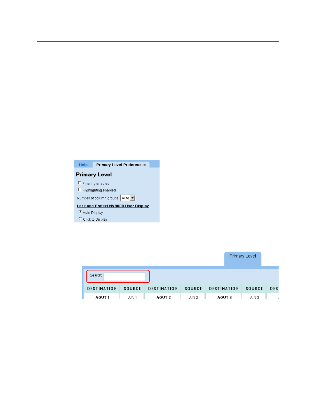
Primary Level Tab
Preferences
By default, the ‘Primary Level’ page displays all destinations defined in the system controller’s
configuration. The Web Suite’s configuration page, however, lets you specify exactly which
destinations are displayed in the list.
You can also specify the number of destination/source pairs to be displayed in each line (in the
page preferences).
You can create more than one ‘Primary Level’ tab. Several ‘Primary Level’ tabs can display
different views of different data.
Sources from tielines are displayed in italics.
Destinations with a breakaway or a level mapping are displayed with the primary source in
See Editing a Primary Level Tab
Preferences
The ‘Primary Level’ page has several user-selectable preferences, available in the sidebar:
underlined text.
on page 41 for information about creating new tabbed pages.
These are the preferences:
• Filtering enabled
Checking this option places a name filter on the page:
You can place text in the ‘Search’ field to limit the number of destination/source pairs that
are displayed. Only those pairs in which the search text appears
or the source
— are displayed.
— in either the destination
• Highlighting enabled
This option allows you to highlight any particular destination/source pair by clicking a field.
The fields are highlighted in a shade of purple.
• Number of column groups
This option lets you specify the number of column pairs in the page. You can set this value to
a number between 1 and 10 or you can specify ‘Auto’ to let the software determine the num-
90
 Loading...