

Page 1

NV8900 Series
MADI Interfaces
User’s Guide
UG0056-03
24 Nov 2014
Page 2

Copyright & Trademark Notice
Copyright © 2014 Miranda. All rights reserved.
Belden, Belden Sending All The Right Signals, and the Belden logo are trademarks or
registered trademarks of Belden Inc. or its affiliated companies in the United States and
other jurisdictions. Miranda, NVISION, NV9000, NV9000-SE Utilities, and NV8900 are
trademarks or registered trademarks of Miranda. Belden Inc., Miranda, and other parties may
also have trademark rights in other terms used herein.
Terms and Conditions
Please read the following terms and conditions carefully. By using NV8900 documentation,
you agree to the following terms and conditions.
Miranda hereby grants permission and license to owners of NV8900 routers to use their
product manuals for their own internal business use. Manuals for Miranda products may not
be reproduced or transmitted in any form or by any means, electronic or mechanical,
including photocopying and recording, for any purpose unless specifically authorized in
writing by Miranda.
A Miranda manual may have been revised to reflect changes made to the product during its
manufacturing life. Thus, different versions of a manual may exist for any given product. Care
should be taken to ensure that one obtains the proper manual version for a specific product
serial number.
Information in this document is subject to change without notice and does not represent a
commitment on the part of Miranda.
Warranty information is available in the support section of the Miranda web site
(www.grassvalley.com).
Title NV8900 User’s Guide
Part Number UG0056-03
Revision 1.3 (24 Nov 14)
ii
Page 3
Change History
Rev. Date ECO Description Approved
1.0 03 Feb 11 — Initial release. D.Cox
1.1 13 Apr 12 19179 Minor corrections.
1.2 24 Apr 13 18826 Some corrections (p. 5) D.Cox
1.3 24 Nov 14 19357 Format change. Added Korean compliance
1.3 24 Nov 14 19357 Reformatted. D.Cox
Safety Compliance
FCC Statement
This equipment has been tested and found to comply with the limits for a Class A digital
device, pursuant to part 15 of the FCC Rules. These limits are designed to provide reasonable
protection against harmful interference when the equipment is operated in a commercial
environment. This equipment generates, uses, and can radiate radio frequency energy and,
if not installed and used in accordance with the instruction manual, may cause harmful
interference to radio communications. Operation of this equipment in a residential area is
likely to cause harmful interference in which case the user will be required to correct the
interference at his own expense.
NV8900
User’s Guide
D.Cox
Added the two analog audio models.
Format change.
D.Cox
statement.
Declaration of Conformance (CE)
All of the equipment described in this manual has been designed to conform with the
required safety and emissions standards of the European Community. Products tested and
verified to meet these standards are marked as required by law with the CE mark.
When shipped into member countries of the European Community, this equipment is
accompanied by authentic copies of original Declarations of Conformance on file in the
Miranda GVD offices in Grass Valley, California USA.
Software License Agreement and Warranty Information
Contact Miranda for details on the software license agreement and product warranty.
Important Safeguards and Notices
This section provides important safety guidelines for operators and service personnel.
Specific warnings and cautions appear throughout the manual where they apply. Please
iii
Page 4
read and follow this important information, especially those instructions related to the risk
of electric shock or injury to persons.
WAR NIN G
Any instructions in this manual that require opening the equipment cover or enclosure are
for use by qualified service personnel only. To reduce the risk of electric shock, do not
perform any service other than that contained in the operating instructions unless you are
qualified to do so.
Restriction on Hazardous Substances (RoHs)
Miranda is in compliance with EU Directive RoHS 2002/95/EC governing the restricted use of
certain hazardous substances and materials in products and in our manufacturing
processes.
Miranda has a substantial program in place for RoHS compliance that includes significant
investment in our manufacturing process, and a migration of Miranda product electronic
components and structural materials to RoHS compliance.
It is our objective at Miranda GVD to maintain compliance with all relevant environmental
and product regulatory requirements. Detailed information on specific products or on the
RoHS program at Miranda is available from Miranda Customer Support at
1-800-719-1900 (toll-free) or
1-530-265-1000 (outside the U.S.).
Symbols and Their Meanings
The lightning flash with arrowhead symbol within an equilateral triangle alerts the
user to the presence of dangerous voltages within the product’s enclosure that
may be of sufficient magnitude to constitute a risk of electric shock to persons.
The exclamation point within an equilateral triangle alerts the user to the presence
of important operating and maintenance/service instructions.
The Ground symbol represents a protective grounding terminal. Such a terminal
must be connected to earth ground prior to making any other connections to the
equipment.
The fuse symbol indicates that the fuse referenced in the text must be replaced
with one having the ratings indicated.
iv
Page 5

NV8900
User’s Guide
The presence of this symbol in or on Miranda equipment means that it has been
designed, tested and certified as complying with applicable Underwriter’s
Laboratory (USA) regulations and recommendations.
The presence of this symbol in or on Miranda equipment means that it has been
designed, tested and certified as essentially complying with all applicable
European Union (CE) regulations and recommendations.
General Warnings
A warning indicates a possible hazard to personnel which may cause injury or death.
Observe the following general warnings when using or working on this equipment:
• Heed all warnings on the unit and in the operating instructions.
• Do not use this equipment in or near water.
• This equipment is grounded through the grounding conductor of the power cord. To
avoid electrical shock, plug the power cord into a properly wired receptacle before connecting the equipment inputs or outputs.
• Route power cords and other cables so they are not likely to be damaged.
• Disconnect power before cleaning the equipment. Do not use liquid or aerosol cleaners; use only a damp cloth.
• Dangerous voltages may exist at several points in this equipment. To avoid injury, do
not touch exposed connections and components while power is on.
• Do not wear rings or wristwatches when troubleshooting high current circuits such as
the power supplies.
• To avoid fire hazard, use only the specified fuse(s) with the correct type number, voltage
and current ratings as referenced in the appropriate locations in the service instructions or on the equipment. Always refer fuse replacements to qualified service personnel.
• To avoid explosion, do not operate this equipment in an explosive atmosphere.
• Have qualified service personnel perform safety checks after any service.
General Cautions
A caution indicates a possible hazard to equipment that could result in equipment damage.
Observe the following cautions when operating or working on this equipment:
• When installing this equipment, do not attach the power cord to building surfaces.
• To prevent damage to equipment when replacing fuses, locate and correct the problem
that caused the fuse to blow before re-applying power.
• Use only the specified replacement parts.
• Follow static precautions at all times when handling this equipment.
• This product should only be powered as described in the manual. To prevent equipment damage, select the proper line voltage on the power supply(ies) as described in
the installation documentation.
v
Page 6

• To prevent damage to the equipment, read the instructions in the equipment manual
for proper input voltage range selection.
• Some products include a backup battery. There is a risk of explosion if the battery is
replaced by a battery of an incorrect type. Dispose of batteries according to instructions.
• Products that have (1) no on/off switch and (2) use an external power supply must be
installed in proximity to a main power outlet that is easily accessible.
• To reduce the risk of electrical shock, plug each power supply cord into a separate
branch circuit having a separate service ground.
vi
Page 7

Table of Contents
1 Preface . . . . . . . . . . . . . . . . . . . . . . . . . . . . . . . . . . . . . . . . . . . . . . . . 1
Chapter Structure . . . . . . . . . . . . . . . . . . . . . . . . . . . . . . . . . . . . . . . . . . . . . . . . . . . . . . . . . . . . . . . . . . . . . . . . . . . . . . 1
The PDF Document . . . . . . . . . . . . . . . . . . . . . . . . . . . . . . . . . . . . . . . . . . . . . . . . . . . . . . . . . . . . . . . . . . . . . . . . . . . . . 1
Terms, Conventions and Abbreviations . . . . . . . . . . . . . . . . . . . . . . . . . . . . . . . . . . . . . . . . . . . . . . . . . . . . . . . . . . 2
2 NV8900 . . . . . . . . . . . . . . . . . . . . . . . . . . . . . . . . . . . . . . . . . . . . . . . . 3
AES Interfaces. . . . . . . . . . . . . . . . . . . . . . . . . . . . . . . . . . . . . . . . . . . . . . . . . . . . . . . . . . . . . . . . . . . . . . . . . . . . . . . . . . . 3
Functions . . . . . . . . . . . . . . . . . . . . . . . . . . . . . . . . . . . . . . . . . . . . . . . . . . . . . . . . . . . . . . . . . . . . . . . . . . . . . 4
Rates. . . . . . . . . . . . . . . . . . . . . . . . . . . . . . . . . . . . . . . . . . . . . . . . . . . . . . . . . . . . . . . . . . . . . . . . . . . . . . . . . . 4
Configuration . . . . . . . . . . . . . . . . . . . . . . . . . . . . . . . . . . . . . . . . . . . . . . . . . . . . . . . . . . . . . . . . . . . . . . . . . 4
Operation . . . . . . . . . . . . . . . . . . . . . . . . . . . . . . . . . . . . . . . . . . . . . . . . . . . . . . . . . . . . . . . . . . . . . . . . . . . . 4
Analog Audio Interfaces. . . . . . . . . . . . . . . . . . . . . . . . . . . . . . . . . . . . . . . . . . . . . . . . . . . . . . . . . . . . . . . . . . . . . . . . . 5
Analog Audio to MADI Interface . . . . . . . . . . . . . . . . . . . . . . . . . . . . . . . . . . . . . . . . . . . . . . . . . . . . . . . . . . . . 6
Function . . . . . . . . . . . . . . . . . . . . . . . . . . . . . . . . . . . . . . . . . . . . . . . . . . . . . . . . . . . . . . . . . . . . . . . . . . . . . . 6
Other LEDs . . . . . . . . . . . . . . . . . . . . . . . . . . . . . . . . . . . . . . . . . . . . . . . . . . . . . . . . . . . . . . . . . . . . . . . . . . . . 6
Signal Connectors . . . . . . . . . . . . . . . . . . . . . . . . . . . . . . . . . . . . . . . . . . . . . . . . . . . . . . . . . . . . . . . . . . . . . 7
DIP Switches . . . . . . . . . . . . . . . . . . . . . . . . . . . . . . . . . . . . . . . . . . . . . . . . . . . . . . . . . . . . . . . . . . . . . . . . . . 7
MADI to Analog Audio Interface . . . . . . . . . . . . . . . . . . . . . . . . . . . . . . . . . . . . . . . . . . . . . . . . . . . . . . . . . . . . 8
Function . . . . . . . . . . . . . . . . . . . . . . . . . . . . . . . . . . . . . . . . . . . . . . . . . . . . . . . . . . . . . . . . . . . . . . . . . . . . . . 8
Other LEDs . . . . . . . . . . . . . . . . . . . . . . . . . . . . . . . . . . . . . . . . . . . . . . . . . . . . . . . . . . . . . . . . . . . . . . . . . . . . 9
Connectors. . . . . . . . . . . . . . . . . . . . . . . . . . . . . . . . . . . . . . . . . . . . . . . . . . . . . . . . . . . . . . . . . . . . . . . . . . . . 9
DIP Switches . . . . . . . . . . . . . . . . . . . . . . . . . . . . . . . . . . . . . . . . . . . . . . . . . . . . . . . . . . . . . . . . . . . . . . . . . 10
Installation. . . . . . . . . . . . . . . . . . . . . . . . . . . . . . . . . . . . . . . . . . . . . . . . . . . . . . . . . . . . . . . . . . . . . . . . . . . . . . . . . . . . . 10
AES Interfaces . . . . . . . . . . . . . . . . . . . . . . . . . . . . . . . . . . . . . . . . . . . . . . . . . . . . . . . . . . . . . . . . . . . . . . . . 10
Analog Audio Interfaces . . . . . . . . . . . . . . . . . . . . . . . . . . . . . . . . . . . . . . . . . . . . . . . . . . . . . . . . . . . . . . 10
3 Misc. Topics . . . . . . . . . . . . . . . . . . . . . . . . . . . . . . . . . . . . . . . . . . . 13
Package Contents . . . . . . . . . . . . . . . . . . . . . . . . . . . . . . . . . . . . . . . . . . . . . . . . . . . . . . . . . . . . . . . . . . . . . . . . . . . . . 13
Installation . . . . . . . . . . . . . . . . . . . . . . . . . . . . . . . . . . . . . . . . . . . . . . . . . . . . . . . . . . . . . . . . . . . . . . . . . . . . . . . . . . . . 13
Obtaining Software and Documentation. . . . . . . . . . . . . . . . . . . . . . . . . . . . . . . . . . . . . . . . . . . . . . . . . . . . . . . . 15
Maintenance . . . . . . . . . . . . . . . . . . . . . . . . . . . . . . . . . . . . . . . . . . . . . . . . . . . . . . . . . . . . . . . . . . . . . . . . . . . . . . . . . . 15
Channel Numbering . . . . . . . . . . . . . . . . . . . . . . . . . . . . . . . . . . . . . . . . . . . . . . . . . . . . . . . . . . . . . . . . . . . . . . . . . . . 15
Audio Rates. . . . . . . . . . . . . . . . . . . . . . . . . . . . . . . . . . . . . . . . . . . . . . . . . . . . . . . . . . . . . . . . . . . . . . . . . . . . . . . . . . . . 15
4 Specifications . . . . . . . . . . . . . . . . . . . . . . . . . . . . . . . . . . . . . . . . . 17
Power Specifications . . . . . . . . . . . . . . . . . . . . . . . . . . . . . . . . . . . . . . . . . . . . . . . . . . . . . . . . . . . . . . . . . . . . . . . . . . . 17
Reference Specifications . . . . . . . . . . . . . . . . . . . . . . . . . . . . . . . . . . . . . . . . . . . . . . . . . . . . . . . . . . . . . . . . . . . . . . . 19
Physical Specifications . . . . . . . . . . . . . . . . . . . . . . . . . . . . . . . . . . . . . . . . . . . . . . . . . . . . . . . . . . . . . . . . . . . . . . . . . 19
Environmental Specifications. . . . . . . . . . . . . . . . . . . . . . . . . . . . . . . . . . . . . . . . . . . . . . . . . . . . . . . . . . . . . . . . . . . 20
Audio Specifications . . . . . . . . . . . . . . . . . . . . . . . . . . . . . . . . . . . . . . . . . . . . . . . . . . . . . . . . . . . . . . . . . . . . . . . . . . . 20
Connectors . . . . . . . . . . . . . . . . . . . . . . . . . . . . . . . . . . . . . . . . . . . . . . . . . . . . . . . . . . . . . . . . . . . . . . . . . . . . . . . . . . . . 22
Serial Connector . . . . . . . . . . . . . . . . . . . . . . . . . . . . . . . . . . . . . . . . . . . . . . . . . . . . . . . . . . . . . . . . . . . . . . . . . . 22
Balanced AES Connectors . . . . . . . . . . . . . . . . . . . . . . . . . . . . . . . . . . . . . . . . . . . . . . . . . . . . . . . . . . . . . . . . . 22
Analog Audio Connectors . . . . . . . . . . . . . . . . . . . . . . . . . . . . . . . . . . . . . . . . . . . . . . . . . . . . . . . . . . . . . . . . . 22
ix
Page 8

Table of Contents
Power Cord Retention . . . . . . . . . . . . . . . . . . . . . . . . . . . . . . . . . . . . . . . . . . . . . . . . . . . . . . . . . . . . . . . . . . . . . . . . . 23
Drawings . . . . . . . . . . . . . . . . . . . . . . . . . . . . . . . . . . . . . . . . . . . . . . . . . . . . . . . . . . . . . . . . . . . . . . . . . . . . . . . . . . . . . . 23
Index . . . . . . . . . . . . . . . . . . . . . . . . . . . . . . . . . . . . . . . . . . . . . . . . . . . . 31
Contact Us . . . . . . . . . . . . . . . . . . . . . . . . . . . . . . . . . . . . . . . . . . . . . . . 35
x
Page 9

Chapter 1 provides an introduction to the NV8900 Series User’s Guide.
Topics
Chapter Structure . . . . . . . . . . . . . . . . . . . . . . . . . . . . . . . . . . . . . . . . . . . . . . . . . . . . . . . . . . . . . . . . . . . . . . . . . 1
The PDF Document . . . . . . . . . . . . . . . . . . . . . . . . . . . . . . . . . . . . . . . . . . . . . . . . . . . . . . . . . . . . . . . . . . . . . . . . 1
Terms, Conventions and Abbreviations . . . . . . . . . . . . . . . . . . . . . . . . . . . . . . . . . . . . . . . . . . . . . . . . . . . . . 2
Chapter Structure
The following chapters provide information regarding the NV8900 MADI Interface:
• Chapter 1, Preface, (this chapter) tells you how to use this guide.
• Chapter 2, NV8900, describes the NV8900, from a user’s standpoint and from a technical
standpoint.
• Chapter 3, Misc. Topics, provides a connection, maintenance, and other information.
• Chapter 4, Specifications, presents the electrical, mechanical, and other specifications for the
NV8900.
An Index
is also available for your reference.
Preface
The PDF Document
This guide is provided in PDF format, allowing you to use Acrobat’s “bookmarks” to navigate to
any desired location. You can also easily print a hardcopy. Please note:
• Use the Table of Contents or the bookmarks page to jump to any desired section.
• Many hyperlinks are provided within the chapters.
• Use the Index to jump to specific topics within a chapter. Each page number in the index is a
hyperlink.
• Use Acrobat’s ‘Go to Previous View’ and ‘Go to Next View’ buttons to retrace your complete
navigational path.
Use the ‘First Page’, ‘Previous Page’, and ‘Next Page’, and ‘Last Page’ buttons to go to the first,
previous, next, or last page within a PDF file.
Note
To display the navigation buttons, right-click the Tool Bar area, and check ‘Navigation’.
• Use Acrobat’s extensive search capabilities, such as the ‘Find’ tool and ‘Search’ tool to per-
form comprehensive searches as required.
1
Page 10

Preface
Terms, Conventions and Abbreviations
Terms, Conventions and Abbreviations
The following conventions are used throughout this guide:
• The symbol denotes either an example or a special message.
• Entries enclosed in single quotes denote the names of control panel buttons and knobs, or
menu items.
Choose ‘Aux’ to ...
Press ‘Keyer 2’ button ...
2
Page 11

NV8900
Chapter 2 provides a functional description of the NV8900 Series interfaces.
Topics
AES Interfaces . . . . . . . . . . . . . . . . . . . . . . . . . . . . . . . . . . . . . . . . . . . . . . . . . . . . . . . . . . . . . . . . . . . . . . . . . . . . . 3
Analog Audio Interfaces
Installation
The NV8900 product family includes 6 MADI interfaces:
• MADI to AES, unbalanced • AES to MADI, unbalanced
• MADI to AES, balanced • AES to MADI, balanced
• MADI to analog audio • Analog audio to MADI
By AES we mean AES-3 and by MADI we mean “multi-channel audio digital interface,”
governed by standard AES10-2003.
The two analog audio interfaces are quite different from the AES interfaces and are discussed
under Analog Audio Interfaces
. . . . . . . . . . . . . . . . . . . . . . . . . . . . . . . . . . . . . . . . . . . . . . . . . . . . . . . . . . . . . . . . . . . . . . . . . . . . . . . 10
. . . . . . . . . . . . . . . . . . . . . . . . . . . . . . . . . . . . . . . . . . . . . . . . . . . . . . . . . . . . . . . . . . . 5
on page 5.
AES Interfaces
The two MADI-to-AES interfaces are demultiplexers that have one MADI input and 32 AES
outputs. The unbalanced outputs use 75W BNCs; the balanced outputs use 110W shielded
twisted pairs on DB25 connectors.
The two AES-to-MADI interfaces are multiplexers that have 32 AES inputs and one MADI output.
The unbalanced inputs use 75 W BNCs; the balanced inputs use 110W shielded twisted pairs on
DB25 connectors.
The MADI inputs and outputs are 75 W BNCs.
The AES-to-MADI interfaces accept up to 64 audio channels. The MADI-to-AES interfaces
produce 64 audio channels. The individual MADI channels are paired on the AES inputs or
outputs. AES connector 1 corresponds to MADI channels 0 and 1; AES connector 2 corresponds
to MADI channels 2 and 3, and so on. AES connector 32 corresponds to MADI channels 62 and
63.
The AES interfaces are 1RU and about 2″ in depth. The following photographs are
representative:
This is a front view of the AES (balanced) to MADI interface. The other AES units resemble this
one, where the difference between the models is the legend.
3
Page 12
NV8900
AES Interfaces
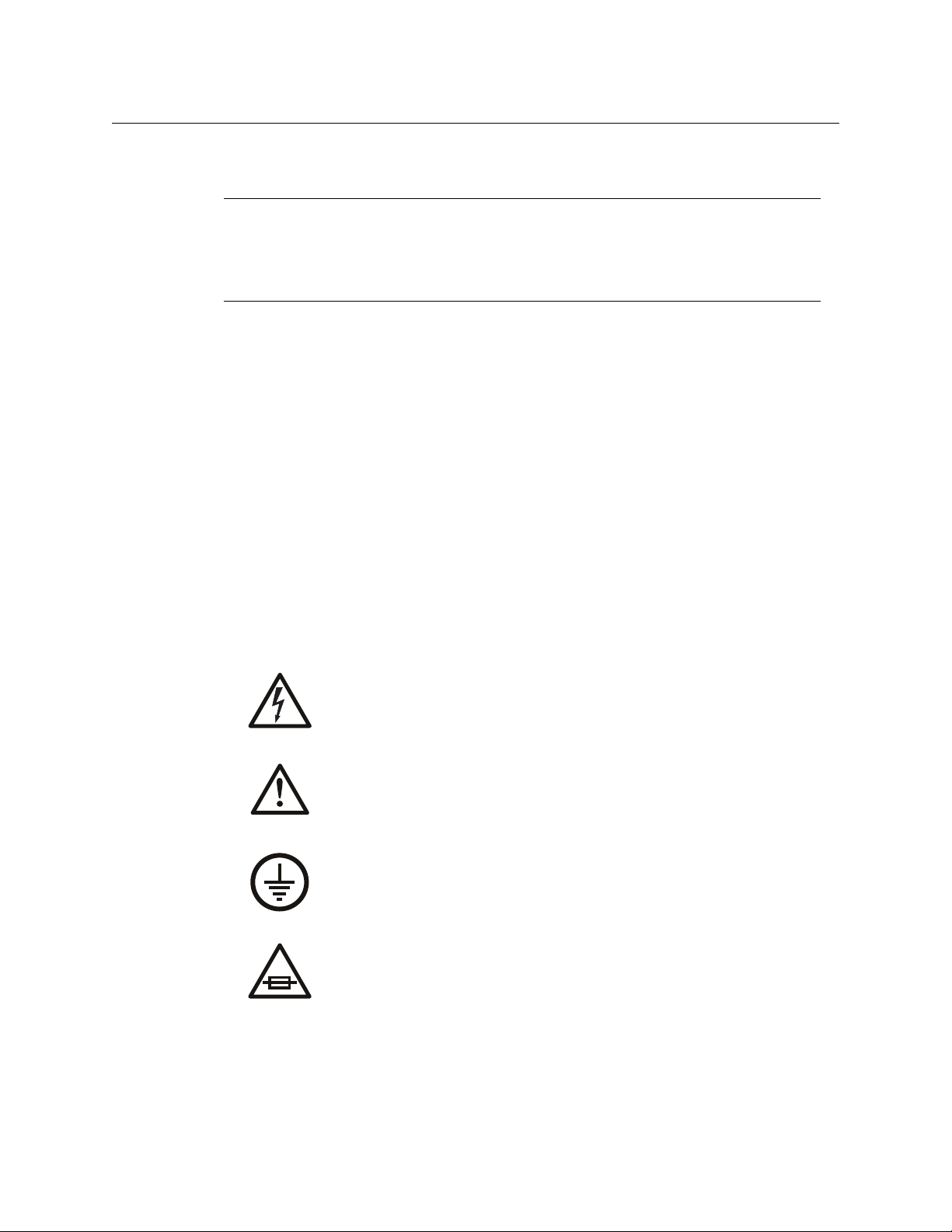
This is a rear view of the AES (balanced) to MADI interface:
It has 4 DB25 connectors supporting the AES inputs. The MADI to AES (balanced) interface is
similar, except for the legend.
This is a rear view of the AES (coax) to MADI interface:
Here, there are 32 BNC connectors supporting the AES inputs. Here, too, the MADI to AES (coax)
interface is similar, except for the legend.
Functions
The AES models convert discrete AES signal pairs to MADI format or vice versa.
The MADI-to-AES interfaces interpret the incoming framing data and preserve VUCP data.
The AES-to-MADI interfaces preserve VUCP and also generate the framing data (in the first 4 bits
of each MADI subframe).
Each interface has a video reference input (loop-through). Each interface has a serial port (DE9)
that is reserved for future use. Each interface has an Ethernet port (RJ-45) for a connection to
MRC (the Miranda Router Configurator).
Each interface has two power connectors (for PS0001 power supply) and a grounding terminal.
Rates
The MADI interfaces send and receive AES at exactly 48.0 kHz (samples per second).
Configuration
You can use MRC (Miranda Router Configurator) to change an NV8900’s IP address and also to
upload firmware.
The NV8900 has a 16-position rotary switch (Frame ID) on the front. This switch exists so that
different NV8900 frames can be distinguished (by MRC) on a network. The switch is not required
for operation.
Operation
The NV8900 AES interfaces function on their own and do not require an operator.
It is sufficient to rack-mount the devices and connect cables to your inputs and outputs.
4
Page 13
Analog Audio Interfaces
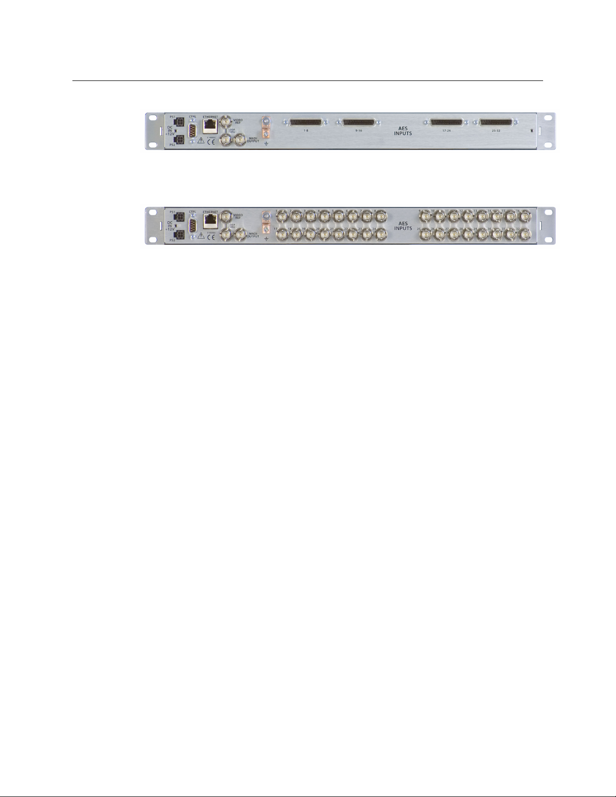
The NV8900 analog audio interfaces are larger, and more complex than, the AES interfaces and
provide a number of status LEDs:
The MADI-to-analog-audio interface is a demultiplexer that has two MADI inputs and 64 analog
audio outputs (32 pairs). The outputs use 110 W shielded twisted pairs on DB25 connectors.
The MADI-to-analog-audio interface interprets the incoming framing data and preserve VUCP
data.
The analog-audio-to-MADI interface is a multiplexer that has 64 analog audio inputs (32 pairs)
and two MADI outputs. The inputs use 110 W shielded twisted pairs on DB25 connectors.
The analog-audio-to-MADI interfaces generate VUCP and also generate the framing data (in the
first 4 bits of each MADI subframe).
The MADI inputs and outputs are 75 W BNCs.
The analog-audio-to-MADI interface accepts 64 audio channels. The MADI-to-analog-audio
interface produces 64 audio channels. The MADI channels are paired on the analog inputs or
outputs.
There are 4 analog audio connector pairs on each of 8 DB25s at the rear of the unit, totalling 64
channels (or 32 channel pairs). Each channel corresponds to 3 pins on a DB25; each channel pair
corresponds to 6 pins. The analog channels are numbered consecutively on the 8 DB25s: 1–8, 9–
16, 17–24, and so on, up to 57–64. See Analog Audio Connectors
Each MADI unit has a video reference input (loop-through). Each interface has a serial port (DE9)
that is reserved for future use. Each interface has an Ethernet port (RJ-45) for a connection to
MRC (the Miranda Router Configurator).
Each unit has two power connectors (for PS0001 power supply) and a grounding terminal.
Each unit is 1RU and 17″ in depth.
NV8900
User’s Guide
on page 22.
5
Page 14
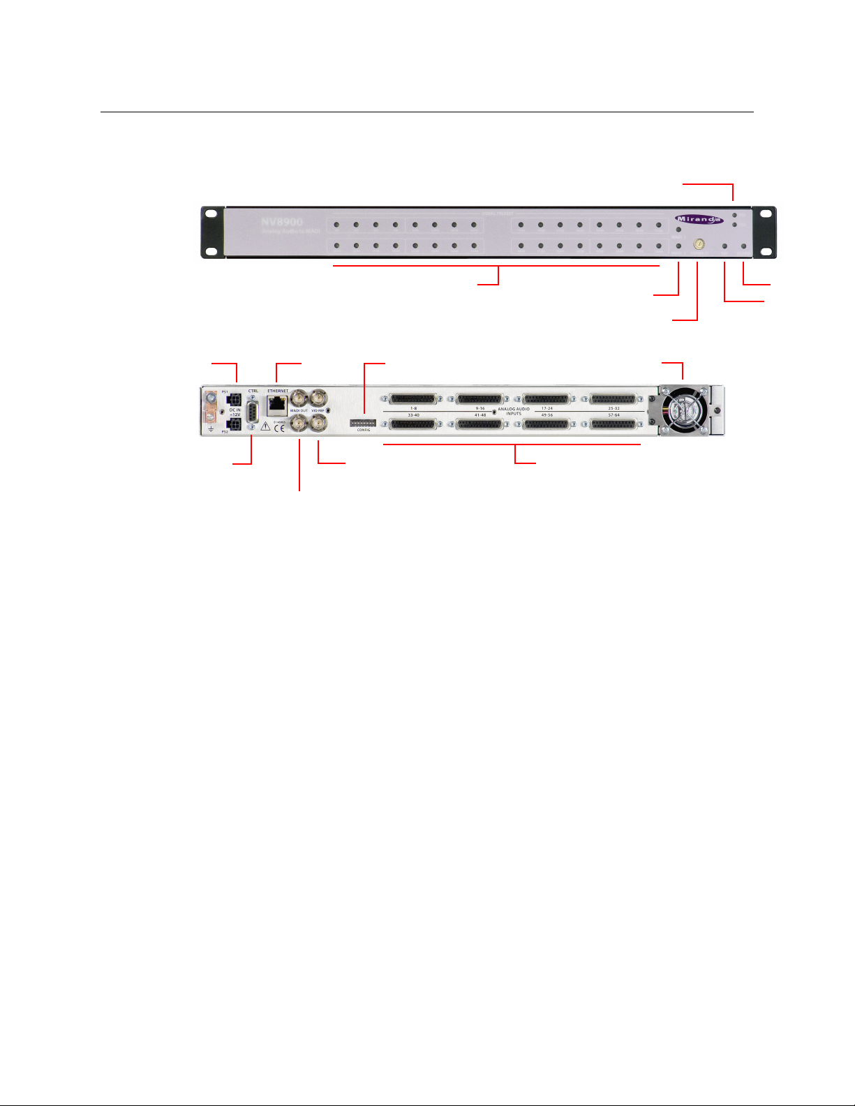
NV8900
Alarm LED
Ref. LED
Rotary Switch
Channel LEDs
Power Supply LEDs
MADI LEDs
Video Reference
(Loop-Through)
Ethernet
Serial
Analog Audio Inputs (DB25)
Fan
MADI Output (2)
DIP Switches
Power (2)
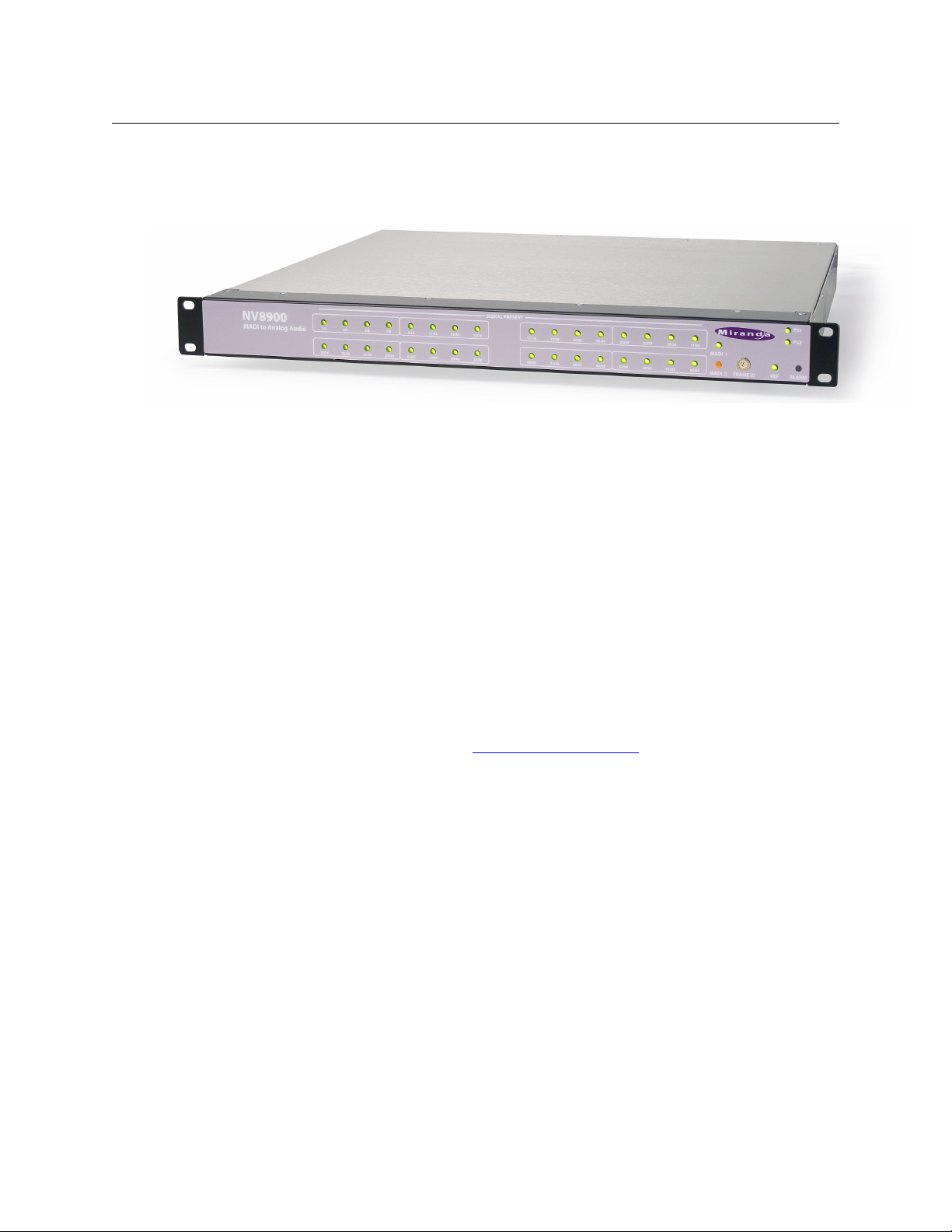
Analog Audio Interfaces
Analog Audio to MADI Interface
This is a front view of the analog-audio-to-MADI interface:
This is a rear view of the analog-audio-to-MADI interface:
Function
The AA-to-MADI interface receives 64 analog audio inputs and produces two MADI outputs,
both identical. The second output is for redundancy.
The 64 inputs are paired internally and are represented by 32 LEDs at the front of the panel, one
for each pair. Each of these LEDs acts as a primitive level meter for the pair, according to the
following scale:
LED state Audio Level Range
Off < –50 dBfs
Green –50 to -4 dBfs
Red > –4 dBfs to 0 dBfs
The unit accepts video reference. It derives its internal clocks from the video reference. It can
free-run, but it is advisable to use an external reference, especially when used with an NV8500
hybrid router.
Other LEDs
Each MADI output is represented by an LED at the front of the unit. The LED is green when the
MADI output is good. Otherwise, the LED is off.
The reference signal is represented by an LED. This LED is green when the reference is good and
red when it is not.
An alarm LED is off under normal operation but turns red for the following conditions:
• Overtemperature
• MADI output failure
• Reference is bad or missing
6
Page 15

NV8900
1ON2345678
SDO8
CTRL
PS1
PS2
DC IN
+12V
E146905
ETHERNET
MADI OUT VID REF
CONFIG
41-48 49-56
ANALOGAUDIO
INPUTS
25-3217-249-161-8
57-6433-40
Analog Inputs (DB25)
Video Reference
(Loop-Through)
MADI Output (2)
DIP Switches (8)
1ON2345678
SDO8
CONFIG
User’s Guide
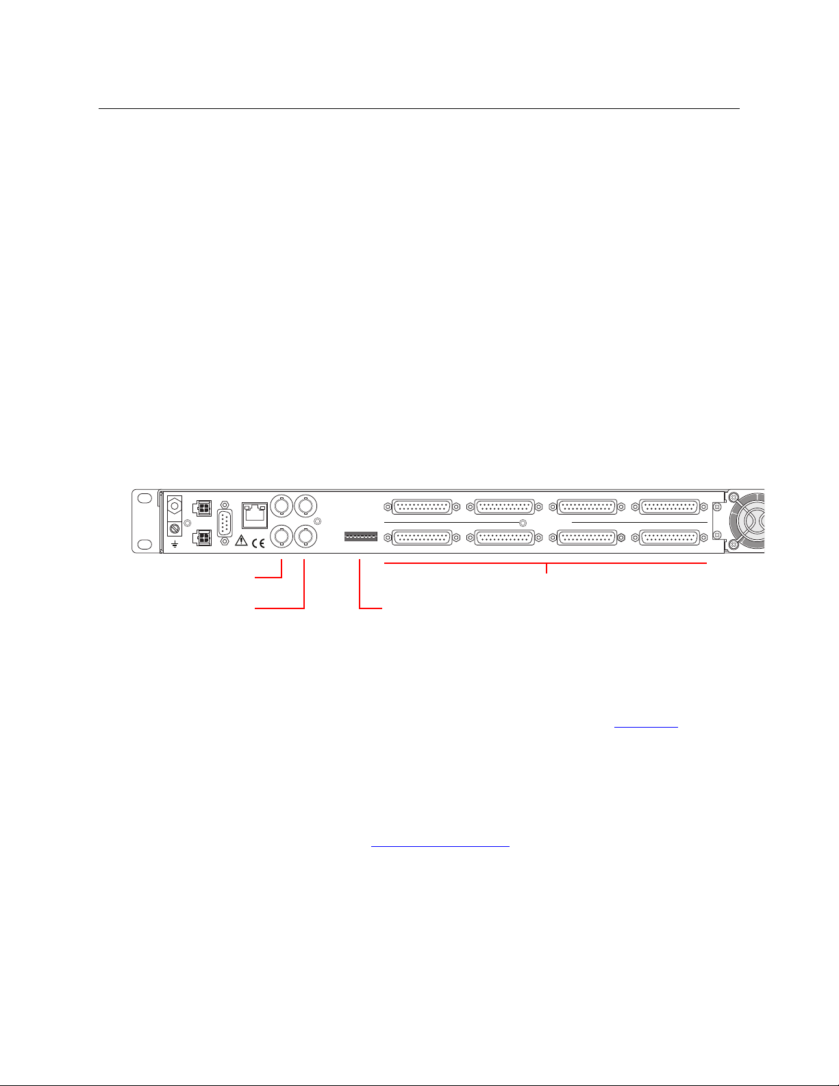
Signal Connectors
At the rear of the AA-to-MADI interface are signal connectors. There are 2 MADI outputs (BNCs),
two video reference connectors (BNC, loop-through), and 8 DB25s for analog audio input.
Each DB25 supports 8 analog audio inputs. The 8 inputs on a connector correspond to an
enclosed section of the labeling on the front of the unit. For instance, first DB25 connector is for
inputs 1 through 8 and the corresponding markings on the front of the unit are pair 1/2, 3/4, 5/6,
and 7/8.
The power connectors, serial port, and Ethernet port are described under Installation
page 13.
Each power connection is represented by an LED at the front of the unit. When the LED is green,
its power supply circuit is good. If the LED is off, the power supply is bad.
The MADI outputs are identical.
The video reference connectors are “loop-through” allowing you to “daisy-chain” a reference
signal to multiple devices. See Reference Specifications
on page 19.
on
DIP Switches
There are 8 DIP switches in a recess at the rear of the unit:
The first 3 switches control the overall audio level of the unit:
Switch Switch
321Level 321Level
000+24 dBu 100+16 dBu
001+22 dBu 101+14 dBu
010+20 dBu 110+12 dBu
011+18 dBU 111+10 dBu
Switches 4–7 are reserved for future use. It does not matter which way these switches are set.
Switch 8 is for factory testing. Leave it off.
7
Page 16

NV8900
Alarm LED
Ref. LED
Rotary Switch
Channel LEDs
Power Supply LEDs
MAD I LEDs
Video Reference
(Loop-Through)
Ethernet
Serial
Analog Audio Outputs (DB25)
Fan
MADI Output (2)
DIP Switches
Power (2)
Analog Audio Interfaces
MADI to Analog Audio Interface
This is a front view of the MADI-to-analog-audio interface:
This is a rear view of the MADI-analog-audio interface:
Function
The MADI-to-AA interface accepts one or two MADI input streams. If it receives two MADI
signals, they should be identical. Only one of the MADI streams is active. The other if it is present,
is stand-by. The stand-by input becomes active if the active input fails.
A failure occurs when the active input has 1 or more bit errors per second for 3 seconds or
more and the stand-by input has no bit errors.
The unit extracts 64 audio channels From the active MADI stream.
The 64 outputs are paired internally and are represented by 32 LEDs at the front of the panel,
one for each pair. Each of these LEDs acts as a primitive level meter for the pair, according to the
following scale:
LED state Audio Level Range
Off < –50 dBfs
Green –50 to -4 dBfs
Red > –4 dBfs to 0 dBfs
The unit accepts video reference. It derives its internal clocks from the video reference. It can
free-run, but it is advisable to use an external reference, especially when used with an NV8500
hybrid router.
8
Page 17
NV8900
1ON2345678
SDO8
CTRL
PS1
PS2
DC IN
+12V
E146905
ETHERNET
MADI OUT VID REF
CONFIG
41-48 49-56
ANALOGAUDIO
INPUTS
25-3217-249-161-8
57-6433-40
Analog Inputs (DB25)
Video Reference
(Loop-Through)
MADI Output (2)
DIP Switches (8)
User’s Guide
Other LEDs
Each MADI input is represented by an LED at the front of the unit. The color of the LED represents the state of the MADI input:
• Green — the MADI input is good and active.
• Amber (or orange) — the MADI input is good and stand-by (inactive).
• Red — the MADI input is bad.
These LEDs behave differently from those of the AA-to-MADI interface.
The reference signal is represented by an LED. This LED is green when the reference is good and
red when it is not.
An alarm LED is off under normal operation but turns red for the following conditions:
• Overtemperature
• MADI output failure
• Reference is bad or missing
Connectors
At the rear of the MADI-to-AA interface are signal connectors. There are 2 MADI outputs (BNCs),
two video reference connectors (BNC, loop-through), and 8 DB25s for analog audio input.
Each DB25 supports 8 analog audio outputs. The 8 outputs of a connector correspond to an
enclosed section of the labeling on the front of the unit. For instance, first DB25 connector is for
outputs 1–8 and the corresponding markings on the front of the unit are pair 1/2, 3/4, 5/6, and
7/8.
The power connectors, serial port, and Ethernet port are described under Installation
on
page 13.
Each power connection is represented by an LED at the front of the unit. When the LED is green,
its power supply circuit is good, and when the LED is off, the power supply circuit is bad.
The MADI inputs are identical.
The video reference connectors are “loop-through” allowing you to “daisy-chain” a reference
signal to multiple devices. See Reference Specifications
on page 19.
9
Page 18

NV8900
1ON2345678
SDO8
CONFIG
Installation
DIP Switches
There are 8 DIP switches in a recess at the rear of the unit:
The first 3 switches control the overall audio level of the unit:
Switch Switch
321Level 321Level
000+24 dBu 100+16 dBu
001+22 dBu 101+14 dBu
010+20 dBu 110+12 dBu
011+18 dBU 111+10 dBu
Switches 4–6 are reserved for future use. It does not matter which way these switches are set.
Switch 7, when it is OFF, enables both MADI inputs. When switch 7 is ON, only the primary MADI
input is enabled. (Switch 7 overrides the unit’s failover behavior. When the switch is ON, the unit
ignores the secondary input and the secondary MADI LED is dark.)
Switch 8 is for factory testing. Leave it off.
Installation
AES Interfaces
The AES interfaces are small and lightweight. It is sufficient to mount them in a 19” rack with
suitable screws.
Analog Audio Interfaces
The analog audio interfaces are large and somewhat heavy and require special hardware that
attaches to, and supports, the rear of the units. There are two metal pieces for each side of the
NV8900:
• ME1714-xx — an 8” extension plate, with screw holes, that attaches to the side of the
NV8900.
• ME1745-xx — a small (1.72”) metal plate that attaches to the rear frame posts.
10
Page 19

NV8900
ME1714-xx
ME1745-xx
ME1714-xx
ME1745-xx
Attach to rear
rack posts.
(front of unit)
User’s Guide
The extension plates fit in the slots of the small plate, and the small plate supports the weight of
the NV8900, as shown:
The (4) metal plates, and screws, are attached to the NV8900 during shipment. Keep them in a
safe place until you are ready to install the NV8900.
The extension plates provide an additional 6.3” of depth, for a total extension of 22.64”. You can
adjust the position of the plate if your rack has less depth.
If your rack does not have rear posts, or if your rack is deeper than 22.64”, consider mounting the
NV8900 just above another device in the rack (say, a router). The other device then supports the
NV8900. Place a non-metal spacer (0.03”) between the NV8900 and the other device.
11
Page 20

NV8900
Installation
12
Page 21

Chapter 3 provides the following:
Topics
Package Contents . . . . . . . . . . . . . . . . . . . . . . . . . . . . . . . . . . . . . . . . . . . . . . . . . . . . . . . . . . . . . . . . . . . . . . . . 13
Installation . . . . . . . . . . . . . . . . . . . . . . . . . . . . . . . . . . . . . . . . . . . . . . . . . . . . . . . . . . . . . . . . . . . . . . . . . . . . . . . 13
Obtaining Software and Documentation . . . . . . . . . . . . . . . . . . . . . . . . . . . . . . . . . . . . . . . . . . . . . . . . . 15
Maintenance . . . . . . . . . . . . . . . . . . . . . . . . . . . . . . . . . . . . . . . . . . . . . . . . . . . . . . . . . . . . . . . . . . . . . . . . . . . . . 15
Channel Numbering . . . . . . . . . . . . . . . . . . . . . . . . . . . . . . . . . . . . . . . . . . . . . . . . . . . . . . . . . . . . . . . . . . . . . . 15
Audio Rates . . . . . . . . . . . . . . . . . . . . . . . . . . . . . . . . . . . . . . . . . . . . . . . . . . . . . . . . . . . . . . . . . . . . . . . . . . . . . . 15
Package Contents
If you have ordered one or more NV8900 products from Miranda, inspect the shipping container
for damage. If you find any container damage, unpack and inspect the contents. If the contents
are damaged, notify the carrier immediately.
As you unpack the shipping container, look for the packing slip and compare it against the
contents to verify that you received everything as ordered. If anything is missing (or if you find
equipment damage unrelated to shipping), please contact technical support. Refer to Grass
Valley Technical Support on page 35.
Depending on your order, the NV8900 items that can ship include:
• One or more NV8900 devices.
• One or more power supplies (PS0001) with power cord retention straps.
The package does not contain network cables, serial cables, or mounting screws.
You do not need to take any special precautions regarding ESD.
This document does not address the shipment or installation of any other equipment or software that can be used in conjunction with the NV8900 (including the NV9000 system controller,
NV915 system controller, and configuration programs such as MRC or NV9000-SE Utilities).
This document does briefly address the use of MRC as it pertain to setting the interfaces’ IP
addresses.
Misc. Topics
Installation
The NV8900 interface(s) are designed to mount in a standard 19″ equipment rack. This is not a
requirement, but we assume a 19″ rack for the sake of simplicity.
Follow these steps to install an NV8900 interface:
1 Set the position of the 16-position rotary switch on the front of the interface.
Set the switch to any non-zero position.
13
Page 22

Misc. Topics
2
1
4
3
Receptacle
n.c.
n.c.
GND
12VDC
4
3
21GND
12 VDC
n.c.
n.c.
Plug
Installation
Although the switch is not used at present, in the future MRC will use the switch position to
distinguish multiple NV8900s on an Ethernet LAN.
Use a small screwdriver to turn the rotary switch.
In a network, all devices must have unique IP addresses. An IP address is determined (at
least initially) by the rotary switch at the front of the MADI interface. The rotary switches
must (at least initially) be distinct.
2 Mount, and secure, the MADI interface in the rack.
For the 1RU interfaces, the mounting holes are spaced 1.25″ (31mm) vertically and allow
approximately 1/8″ (3mm) of movement horizontally.
For the 2RU interfaces, the 3 mounting holes on each side are spaced 1.25″ (31mm) and
1.75″ (44mm) (3″, 76mm, overall) vertically and allow approximately 1/8″ (3mm) of play horizontally.
You might not have enough space to reach behind the MADI interface and make
connections. In that case, leave this step until last.
3 If you are using the MADI interface on a network (for MRC), connect an Ethernet cable (RJ-
45) from the network switch to the Ethernet port of the MADI interface. Also connect an
Ethernet cable from your PC running MRC to the Ethernet switch.
4 Connect your video reference.
Each MADI interface has two video reference BNC connectors. You can connect a reference
source to either one. You can “daisy chain” the output of one reference connector to the
input of another. The output of the last connector in the series should be terminated with a
75Ω BNC terminator.
Your MADI interfaces must use the same video reference as your router (especially an
NV8500 family hybrid router).
5 Optionally connect the ground lug to earth ground. Use copper wire from 14 to 6 AWG.
Grounding decisions are left to you or your facilities manager. Failure to connect the ground
will not affect normal operation, but connecting the ground will protect you and your equipment in a power anomaly such as a lightning strike.
6 Connect one or both power supplies. First connect the 4-pin connector to PS1 or PS2 on the
rear of the router. The connectors are keyed and snap into place. There is only one way they
fit. Do not force them. Then connect the power supply to AC power.
14
The second power connection is for redundancy only (protection against failure) and is not a
requirement for operation.
7 Connect input devices and output devices. No particular order or combination is required.
Some of the MADI interfaces use standard 75Ω BNC connectors.
Some of the MADI interfaces use DB25 connectors. You can obtain DB25 breakout cables
from Miranda or build your own cables. (The Miranda part number is WC0053. The sales
order code is NV5000-CABLE1.)
Page 23

Obtaining Software and Documentation
This document is available through the Miranda web site.
Maintenance
The NV8900 requires no maintenance.
Channel Numbering
The MADI interfaces support 64 audio channels, 0–63. The MADI channels are paired on the AES
inputs or outputs.
Use the following formula to calculate a port number, given a MADI channel number:
p = m
/ 2
+ 1 0 ≤ m ≤ 63.
Use the following formulas to calculate a MADI channel pair, given a port number:
m
= p × 2 – 2 1 ≤ p ≤ 32.
1
m
= p × 2 – 1
2
NV8900
User’s Guide
Audio Rates
According to the MADI specification, MADI receivers and drivers operate at 125MHz which
supports 100M bits per second under 4B5B encoding. The receivers expect and the drivers
produce 64 audio channels at exactly 48
1.7% margin for sync symbols and padding.
At least one sync symbol must accompany every MADI frame. The minimal number of sync
symbols is 48,000 per second. At 10 bits per symbol, that is 480,000 bits out of 2,120,000 spare
bits.
The AES10-2003 specification’s tolerance on the transmission rate is 100 ppm (10
rate must be 125MHz ± 12,500kHz.
Our MADI interfaces send and receive AES at 48.0kHz exactly. The data rate is, of course,
kHz. The 64 channels consume 98,304,000 bps with a
–4
). Thus the
affected by the actual transmission rate. The effect on a 48 kHz data rate is a variance of ±
4.8Hz.
15
Page 24

Misc. Topics
Audio Rates
16
Page 25

Chapter 4 provides an introduction to the NV8900 Series User’s Guide.
Topics
Power Specifications . . . . . . . . . . . . . . . . . . . . . . . . . . . . . . . . . . . . . . . . . . . . . . . . . . . . . . . . . . . . . . . . . . . . . . 17
Reference Specifications
Environmental Specifications
Physical Specifications
Audio Specifications
Connectors
Power Cord Retention
Drawings
. . . . . . . . . . . . . . . . . . . . . . . . . . . . . . . . . . . . . . . . . . . . . . . . . . . . . . . . . . . . . . . . . . . . . . . . . . . . . . . 22
. . . . . . . . . . . . . . . . . . . . . . . . . . . . . . . . . . . . . . . . . . . . . . . . . . . . . . . . . . . . . . . . . . . . . . . . . . . . . . . . . 23
Power Specifications
NV8900 AES Power Specifications
These specifications are applicable to the 4 AES models:
• AES-to-MADI, balanced • MADI-to-AES, balanced
• AES-to-MADI, coax • MADI-to-AES, coax
Specifications
. . . . . . . . . . . . . . . . . . . . . . . . . . . . . . . . . . . . . . . . . . . . . . . . . . . . . . . . . . . . . . . . . . 19
. . . . . . . . . . . . . . . . . . . . . . . . . . . . . . . . . . . . . . . . . . . . . . . . . . . . . . . . . . . . . 20
. . . . . . . . . . . . . . . . . . . . . . . . . . . . . . . . . . . . . . . . . . . . . . . . . . . . . . . . . . . . . . . . . . . . 19
. . . . . . . . . . . . . . . . . . . . . . . . . . . . . . . . . . . . . . . . . . . . . . . . . . . . . . . . . . . . . . . . . . . . . . 20
. . . . . . . . . . . . . . . . . . . . . . . . . . . . . . . . . . . . . . . . . . . . . . . . . . . . . . . . . . . . . . . . . . . . 23
Specification Detail
DC power External power supply: 12VDC ± 10%, 5A.
Power consumption Each device consumes less than 10 Watts.
Regulatory UL listed and CE compliant.
NV8900 Analog Audio to MADI Power Specifications
Specification Detail
DC power External power supply: 12VDC ± 10%, 5A.
Power consumption Each device consumes less than 30 Watts.
Regulatory UL listed and CE compliant.
NV8900 MADI to Analog Audio Power Specifications
This rating is subject to driving loads of 10 kW or more.
Specification Detail
DC power External power supply: 12VDC ± 10%, 5A.
17
Page 26

Specifications
Indicator LED
5.24
[133.0]
2.39
[60.7]
AC Input
1.62
[41.0]
DC Output
Power Specifications
Specification Detail
Power consumption Each device consumes less than 45 Watts.
Regulatory UL listed and CE compliant.
Power Supply Specifications
Specification Detail
AC power 90–264 VAC (127–300VDC), 47–447Hz.
Inrush current < 50A at 230 VAC, cold start, at 25°C,
Input current < 2.0A rms at 115VAC; < 1.0A at 230VAC.
DC power ≤ 60W, 12VDC, 5A (5.4A peak), Regulation ± 2%. Ripple ≤ 120mV.
Efficiency Efficiency > 80% at full load typical, 115VAC.
Weight 1.06 lb (0.48 kg).
Regulatory UL Listed and CE Compliant.
The power supply is an Miranda PS0001-00:
18
The power output has Molex 4-pin plug. See Power Cord Retention
on page 23.
Page 27

Reference Specifications
NV8900 Video Reference Specifications.
Detail
Connectors: 2 BNC (1 pair, loop-through), non-terminating, 75Ω characteristic impedance.
Acceptable video reference rates:
NTSC
PAL 25 Hz frame rate 625 lines/frame
HD Trilevel (24/1.001) Hz frame rate 1080p
Input level range: 500
Input return loss: > 40
(30/1.001) Hz frame rate 525 lines/frame
24 Hz frame rate 1080p
25 Hz frame rate 1080i
(30/1.001) Hz frame rate 1080i
30 Hz frame rate 1080i
50 Hz frame rate 1080p, 720p
(60/1.001) Hz frame rate 1080p, 720p
60 Hz frame rate 1080p, 720p
mV p-p to 2 V p-p
dB, to 6 MHz
NV8900
User’s Guide
Physical Specifications
Specifications for AES Interfaces
Specification Detail
Dimensions Height: 1.72″ (43.7 mm), fits EIA 1 RU (1.75″ or 44.5mm).
Weight MADI to AES, balanced: 1.65 lb (0.748kg)
Connectors Power: 2 connectors, Molex 4-pin, keyed.
Grounding terminal Copper, accepts 14–6 AWG.
Width: 19.0″ (482.6 mm).
Depth: 1.53 ±0.01″ (38.7mm), enclosure; 2.19″ (55.6mm) overall,
including connectors.
MADI to AES, coax: 2.15 lb (0.977kg)
AES to MADI, balanced: 1.65 lb (0.748kg)
AES to MADI, coax: 2.15 lb (0.977kg)
Ethernet: 1 connector, 10/100BaseT, RJ-45 jack.
RS-422: 1 connector, 9-pin D type, usage determined by software, SMPTE
207M.
Video reference: 2 connectors, BNC, 75Ω.
Coax: 33 BNC, 75Ω, connectors.
Balanced: 4 DB25, 110 Ω, and 1 BNC, 75Ω
19
Page 28

Specifications
Environmental Specifications
Specifications for Analog Audio Interfaces
Specification Detail
Dimensions Height: 1.72″ (43.7 mm), fits EIA 1 RU (1.75″ or 44.5mm).
Width: 19.0″ (482.6 mm).
Depth: 16.34 ±0.01″ (415.0mm), enclosure; 17.00″ (431.8 mm) overall,
including connectors.
Weight (Both units) 2.93 kg (6.46 lb)
Connectors Power: 2 connectors, Molex 4-pin, keyed.
Ethernet: 1 connector, 10/100BaseT, RJ-45 jack.
RS-422: 1 connector, 9-pin D type, usage determined by software, SMPTE
207M.
Video reference: 2 connectors, BNC, 75Ω.
MADI: 2 connectors, BNC, 75Ω.
Analog audio: 8 DB25, 110Ω
Grounding terminal Copper, accepts 14–6 AWG.
Environmental Specifications
NV8900 Environmental Specifications.
Specification Detail
Operating temperature 0–40°C, ambient.
Relative humidity 0 to 90%, non-condensing.
Cooling No fan required
Audio Specifications
NV8900 AES Coax Specifications.
Specification Detail
Signal inputs Signal type: AES-3id (2 “mono” channels per input).
Signal outputs Signal type: AES-3id (2 “mono” channels per input).
Sample rate: 48kHz.
Input level: 1Vp-p ± 20% into 75Ω.
Input range: 320 mVp-p to 1Vp-p into 75 Ω.
Input return loss: < –15dB, from 100 kHz to 6MHz.
Input connectors: BNC, 75Ω.
Sample rate: 48kHz.
Output level: 1 V p-p ± 20% into 75Ω.
Output return loss: < –15dB, from 100kHz to 6MHz.
Output connectors: BNC, 75Ω.
20
Page 29

NV8900 AES Balanced Specifications.
Specification Detail
Signal inputs Signal type: AES-3 (2 “mono” channels per input).
Sample rate: 48kHz.
Input level: 1Vp-p nominal into 110 Ω.
Input range: 200mVp-p to 10Vp-p into 110 Ω.
Input connectors: DB25, 110 Ω.
Signal outputs Signal type: AES-3 (2 “mono” channels per input).
Sample rate: 48kHz.
Output level: 2–7Vp-p into 75Ω.
Output return loss: < –25dB, from 100 kHz to 6MHz.
Output connectors: BNC, 75Ω.
NV8900 Analog Audio Specifications
Specification Detail
Signal inputs Input level: 10–24dBu.
Input impedance: > 20 kW.
Input CMRR: > 90dBu, at 60Hz.
Frequency response: < ± 0.2dB from 20 Hz to 100kHz.
THD: –87dB at 1kHz, 20 to 20 kHz.
Crosstalk: > –100dB, at 1 kHz.
SNR: > 106dB, A weighted (20Hz to 20kHz).
Input connectors: DB25.
Signal outputs Output level: 10–24dBu.
Input to output level variations: ± 1dB, nominal.
Frequency response: < ± 0.2dB from 20 Hz to 100kHz.
Output impedance: 50W, nominal.
THD: –87dB at 1kHz, 20 to 20 kHz.
Crosstalk: > –100dB, at 1 kHz.
SNR: > 106dB, A weighted (20Hz to 20kHz).
Output connectors: DB25.
NV8900
User’s Guide
NV8900 MADI Specifications.
Specification Detail
Connector BNC
Impedance 75 W
Input level 150 mV to 600mV
Output level 600mV
Cable length < 300 m
21
Page 30

Specifications
5
1
6
9
Gnd
TX
RX+
Gnd
n.c.
Gnd
TX+
RX
Gnd
(n.c.) 13
No. 2
No. 4
No. 8
No. 6
11
23
10
8
20
7
5
17
4
2
14
1
No. 1
No. 3
No. 7
No. 5
25
12
24
22
9
21
19
6
18
16
3
15
1
1425
SHIELD
+
SHIELD
+
SHIELD
+
SHIELD
+
SHIELD
+
SHIELD
+
SHIELD
+
SHIELD
+
No. 2
(R1)
13 (n.c.)
No. 4
(R2)
No. 8
(R4)
No. 6
(R3)
11
23
10
8
20
7
5
17
4
2
14
1
No. 1
(L1)
No. 3
(L2)
No. 7
(L4)
No. 5
(L3)
25
12
24
22
9
21
19
6
18
16
3
15
1
1425
SHIELD
+
SHIELD
+
SHIELD
+
SHIELD
+
SHIELD
+
SHIELD
+
SHIELD
+
SHIELD
+
Connectors
Connectors
Serial Connector
The serial connector for all NV8900 MADI Interfaces has this pinout:
The connector is RS-485, female, but can be used as RS-422.
However, the port is unused and reserved for future expansion.
Balanced AES Connectors
Balanced AES inputs and outputs use 110 Ω DB25 connectors, all female. Each connector
supports 8 inputs (or outputs):
Analog Audio Connectors
Analog audio inputs and outputs use 110Ω DB25 connectors, all female. Each connector
supports 8 inputs (or outputs):
The inputs are paired consecutively:
(L1,R1) = ports 1 and 2 (L2,R2) = ports 3 and 4
22
(L3,R3) = ports 5 and 6 (L4,R4) = ports 7 and 8
Page 31

Power Cord Retention
Use the supplied retention strap to keep the AC power cord firmly connected to the power
supply. Follow these steps to use the strap:
1 Firmly insert the AC power cord into the power supply. Examine the last figure in this section
to see how the strap should be applied.
2 Placed the Velcro retention strap, fuzzy side up, on top of the power supply with the buckle
loop approximately 1 inch from the AC input side and the remaining strap around the cord
end and down:
3 Holding the buckle in place, lift the strap up and around the cord end so the strap overlaps
itself:
NV8900
User’s Guide
Drawings
4 Holding the buckle loop in place, route the strap around the back of the supply diagonally
across so that it sticks out on the left below the output cord:
5 Continue the strap around toward the buckle loop and through the loop. Cinch the strap
tightly. While keeping tension, place the 2 inch strap end (with Velcro loops) down on the
fuzzy part to complete the process:
6 Examine the strap though its path around the cord and power supply. Be sure that no slack
exists and that it is tight the full length of the strap. If necessary, adjust and cinch it more
tightly.
Drawings follow on the next few pages.
23
Page 32

Specifications
19.0 [482.6]
1.25
[31.75]
1.72
[43.78]
19.0 [482.6]
17.24 [437.9]
1.25
[31.75]
1.72
[43.78]
1.53
[38.9]
2.19
[55.6]
Drawings
24
Fig. 4-1: Front, Top, and Rear Views of the Balanced MADI to AES Interface
Page 33

NV8900
19.0 [482.6]
1.25
[31.75]
1.72
[43.78]
19.0 [482.6]
17.24 [437.9]
1.25
[31.75]
1.72
[43.78]
1.53
[38.9]
2.19
[55.6]
User’s Guide
Fig. 4-2: Front, Top, and Rear Views of the Coax MADI to AES Interface
25
Page 34

Specifications
19.0 [482.6]
1.25
[31.75]
1.72
[43.78]
19.0 [482.6]
17.24 [437.9]
1.25
[31.75]
1.72
[43.78]
1.53
[38.9]
2.19
[55.6]
Drawings
26
Fig. 4-3: Front, Top, and Rear Views of the Balanced AES to MADI Interface
Page 35

NV8900
19.0 [482.6]
1.25
[31.75]
1.72
[43.78]
19.0 [482.6]
17.24 [437.9]
1.25
[31.75]
1.72
[43.78]
1.53
[38.9]
2.19
[55.6]
User’s Guide
Fig. 4-4: Front, Top, and Rear Views of the Coax AES to MADI Interface
27
Page 36

Specifications
FRAME ID REF ALARM
MADI 1
MADI 2
PS2
PS1
Analog Audio to MADI
NV8900
SIGNAL PRESENT
17/18 19/20 21/22 23/24 25/26 27/28 29/30 31/321/2 3/4 5/6 7/8 9/10 11/12 13/14 15/16
49/50 51/52 53/54 55/56 57/58 59/60 61/62 63/64
33/34 35/36 37/38 39/40 41/42 43/44 45/46 47/48
19.0 [482.6]
1.25
[31.75]
1.72
[43.78]
1
ON
2345678
SDO8
CTRL
PS1
PS2
DC IN
+12V
E146905
ETHERNET
MADI OUT VID REF
CONFIG
41-48 49-56
ANALOG AUDIO
INPUTS
25-3217-249-161-8
57-6433-40
19.0 [482.6]
1.25
[31.75]
1.72
[43.78]
17.00
[431.8]
16.34
[415.04]
Drawings
28
Fig. 4-5: Front, Top, and Rear Views of the Analog Audio to MADI Interface
Page 37

NV8900
FRAME ID REF ALARM
MADI 1
MADI 2
PS2
PS1
MADI to Analog Audio
NV8900
SIGNAL PRESENT
17/18 19/20 21/22 23/24 25/26 27/28 29/30 31/321/2 3/4 5/6 7/8 9/10 11/12 13/14 15/16
49/50 51/52 53/54 55/56 57/58 59/60 61/62 63/6433/34 35/36 37/38 39/40 41/42 43/44 45/46 47/48
19.0 [482.6]
1.25
[31.75]
1.72
[43.78]
1
ON
2345678
SDO8
CTRL
PS1
PS2
DC IN
+12V
E146905
ETHERNET
MADI IN VID REF
CONFIG
41-48 49-56
ANALOG AUDIO
OUTPUTS
25-3217-249-161-8
57-6433-40
19.0 [482.6]
1.25
[31.75]
1.72
[43.78]
17.00
[431.8]
16.34
[415.04]
User’s Guide
Fig. 4-6: Front, Top, and Rear Views of the MADI to Analog Audio Interface
29
Page 38

Specifications
Drawings
30
Page 39

Index
A
Abbreviations . . . . . . . . . . . . . . . . . . . . . . . . . . . . . . . . . . . . . . . . 2
Acrobat usage . . . . . . . . . . . . . . . . . . . . . . . . . . . . . . . . . . . . . . . . 1
bookmarks . . . . . . . . . . . . . . . . . . . . . . . . . . . . . . . . . . . . . . . 1
hyperlinks . . . . . . . . . . . . . . . . . . . . . . . . . . . . . . . . . . . . . . . . 1
navigating and searching . . . . . . . . . . . . . . . . . . . . . . . . . 1
Africa, contact . . . . . . . . . . . . . . . . . . . . . . . . . . . . . . . . . . . . . . . 35
agreement, license . . . . . . . . . . . . . . . . . . . . . . . . . . . . . . . . . . . v
Americas, contact . . . . . . . . . . . . . . . . . . . . . . . . . . . . . . . . . . . . 35
Analog
audio specifications . . . . . . . . . . . . . . . . . . . . . . . . . . . . . 21
Asia, contact . . . . . . . . . . . . . . . . . . . . . . . . . . . . . . . . . . . . . . . . . 35
Audio
specifications, analog . . . . . . . . . . . . . . . . . . . . . . . . . . . . 21
specifications, digital . . . . . . . . . . . . . . . . . . . . . . . . 20–21
Automation connector . . . . . . . . . . . . . . . . . . . . . . . . . . . . . . . 22
B
Balanced AES to MADI mux . . . . . . . . . . . . . . . . . . . . . . . . . . 26
Balanced MADI to AES demux . . . . . . . . . . . . . . . . . . . . . . . . 24
BNC connectors . . . . . . . . . . . . . . . . . . . . . . . . . . . . . . . . . . . . . 14
Bookmarks, Acrobat . . . . . . . . . . . . . . . . . . . . . . . . . . . . . . . . . . 1
Breakout cable, WC0053 . . . . . . . . . . . . . . . . . . . . . . . . . . . . . 14
C
Cable
Ethernet . . . . . . . . . . . . . . . . . . . . . . . . . . . . . . . . . . . . . . . . . 14
cautions . . . . . . . . . . . . . . . . . . . . . . . . . . . . . . . . . . . . . . . . . . . . . vii
CE . . . . . . . . . . . . . . . . . . . . . . . . . . . . . . . . . . . . . . . . . . . . . . . . . . . . iv
change history . . . . . . . . . . . . . . . . . . . . . . . . . . . . . . . . . . . . . . .iv
Channel numbering . . . . . . . . . . . . . . . . . . . . . . . . . . . . . . . . . 15
Chapter structure . . . . . . . . . . . . . . . . . . . . . . . . . . . . . . . . . . . . . 1
Chapters
1, Preface . . . . . . . . . . . . . . . . . . . . . . . . . . . . . . . . . . . . . . . . . 1
2, NV8900 . . . . . . . . . . . . . . . . . . . . . . . . . . . . . . . . . . . . . . . . 3
3, Misc. Topics . . . . . . . . . . . . . . . . . . . . . . . . . . . . . . . . . . . 13
4, Specifications . . . . . . . . . . . . . . . . . . . . . . . . . . . . . . . . . 17
China, contact . . . . . . . . . . . . . . . . . . . . . . . . . . . . . . . . . . . . . . . 35
Coax AES to MADI mux . . . . . . . . . . . . . . . . . . . . . . . . . . 27–29
Coax MADI to AES demux . . . . . . . . . . . . . . . . . . . . . . . . . . . . 25
Compact router . . . . . . . . . . . . . . . . . . . . . . . . . . . . . . . . . .13, 22
Configuration . . . . . . . . . . . . . . . . . . . . . . . . . . . . . . . . . . . . . . . . 4
Connectors
automation . . . . . . . . . . . . . . . . . . . . . . . . . . . . . . . . . . . . . .22
BNC . . . . . . . . . . . . . . . . . . . . . . . . . . . . . . . . . . . . . . . . . . . . .14
DB25 . . . . . . . . . . . . . . . . . . . . . . . . . . . . . . . . . . . . . . . . . . . .14
DE9 . . . . . . . . . . . . . . . . . . . . . . . . . . . . . . . . . . . . . . . . . . . . . .22
power . . . . . . . . . . . . . . . . . . . . . . . . . . . . . . . . . . . . . . . . . . .14
Contact Miranda . . . . . . . . . . . . . . . . . . . . . . . . . . . . . . . . . . . . .35
Control panel . . . . . . . . . . . . . . . . . . . . . . . . . . . . . . . . . . . . . . . .13
Conventions . . . . . . . . . . . . . . . . . . . . . . . . . . . . . . . . . . . . . . . . . . 2
Corporate office, contact . . . . . . . . . . . . . . . . . . . . . . . . . . . . .35
CR Series . . . . . . . . . . . . . . . . . . . . . . . . . . . . . . . . . . . . . . . . . . . . .22
Customer support . . . . . . . . . . . . . . . . . . . . . . . . . . . . . . . . . . . .35
D
DB25 connectors . . . . . . . . . . . . . . . . . . . . . . . . . . . . . . . . . . . . .14
DE9 connectors . . . . . . . . . . . . . . . . . . . . . . . . . . . . . . . . . . . . . .22
Declaration of Conformance . . . . . . . . . . . . . . . . . . . . . . . . . . iv
Digital audio
specifications . . . . . . . . . . . . . . . . . . . . . . . . . . . . . . . . 20–21
document
notice of use . . . . . . . . . . . . . . . . . . . . . . . . . . . . . . . . . . . . . iv
revision . . . . . . . . . . . . . . . . . . . . . . . . . . . . . . . . . . . . . . . . . . iv
Documentation . . . . . . . . . . . . . . . . . . . . . . . . . . . . . . . . . . . . . .15
abbreviations . . . . . . . . . . . . . . . . . . . . . . . . . . . . . . . . . . . . . 2
conventions . . . . . . . . . . . . . . . . . . . . . . . . . . . . . . . . . . . . . .2
symbols . . . . . . . . . . . . . . . . . . . . . . . . . . . . . . . . . . . . . . . . . .2
terms . . . . . . . . . . . . . . . . . . . . . . . . . . . . . . . . . . . . . . . . . . . . .2
Drawings
balanced AES to MADI mux . . . . . . . . . . . . . . . . . . . . . . .26
balanced MADI to AES demux . . . . . . . . . . . . . . . . . . . .24
coax AES to MADI mux . . . . . . . . . . . . . . . . . . . . . . . 27–29
coax MADI to AES demux . . . . . . . . . . . . . . . . . . . . . . . . .25
E
Electrical specifications
power supply . . . . . . . . . . . . . . . . . . . . . . . . . . . . . . . . . . . .18
Electrostatic discharge . . . . . . . . . . . . . . . . . . . . . . . . . . . . . . .13
E-mail address . . . . . . . . . . . . . . . . . . . . . . . . . . . . . . . . . . . . . . .35
Environmental specifications . . . . . . . . . . . . . . . . . . . . . . . . .20
ESD . . . . . . . . . . . . . . . . . . . . . . . . . . . . . . . . . . . . . . . . . . . . . . . . . .13
Ethernet
cable . . . . . . . . . . . . . . . . . . . . . . . . . . . . . . . . . . . . . . . . . . . .14
Europe, contact . . . . . . . . . . . . . . . . . . . . . . . . . . . . . . . . . . . . . .35
Examples, symbol for . . . . . . . . . . . . . . . . . . . . . . . . . . . . . . . . . .2
31
Page 40

Index
F
Fan . . . . . . . . . . . . . . . . . . . . . . . . . . . . . . . . . . . . . . . . . . . . . . . . . . 20
Fax number . . . . . . . . . . . . . . . . . . . . . . . . . . . . . . . . . . . . . . . . . 35
FCC statement . . . . . . . . . . . . . . . . . . . . . . . . . . . . . . . . . . . . . . . . iv
Figures
balanced AES to MADI mux . . . . . . . . . . . . . . . . . . . . . . 26
balanced MADI to AES demux . . . . . . . . . . . . . . . . . . . . 24
coax AES to MADI mux . . . . . . . . . . . . . . . . . . . . . . . 27–29
coax MADI to AES demux . . . . . . . . . . . . . . . . . . . . . . . . 25
Find, Acrobat . . . . . . . . . . . . . . . . . . . . . . . . . . . . . . . . . . . . . . . . . 1
First Page, Acrobat . . . . . . . . . . . . . . . . . . . . . . . . . . . . . . . . . . . . 1
France, contact . . . . . . . . . . . . . . . . . . . . . . . . . . . . . . . . . . . . . . 35
Functions . . . . . . . . . . . . . . . . . . . . . . . . . . . . . . . . . . . . . . . . . . . . 4
G
General specifications, NV5500 . . . . . . . . . . . . . . . . . . . . . . . 19
Go to Next View, Acrobat . . . . . . . . . . . . . . . . . . . . . . . . . . . . . 1
Go to Previous View, Acrobat . . . . . . . . . . . . . . . . . . . . . . . . . 1
Grounding terminal . . . . . . . . . . . . . . . . . . . . . . . . . . . . . . . . . 14
H
hardware symbols . . . . . . . . . . . . . . . . . . . . . . . . . . . . . . . . . . . . vi
hazardous substance . . . . . . . . . . . . . . . . . . . . . . . . . . . . . . . . . v
HD sync . . . . . . . . . . . . . . . . . . . . . . . . . . . . . . . . . . . . . . . . . . . . . 19
Hours of operation . . . . . . . . . . . . . . . . . . . . . . . . . . . . . . . . . . 35
How to
install the router . . . . . . . . . . . . . . . . . . . . . . . . . . . . . . . . . 13
How to use this guide . . . . . . . . . . . . . . . . . . . . . . . . . . . . . . . . . 1
Hyperlinks, Acrobat . . . . . . . . . . . . . . . . . . . . . . . . . . . . . . . . . . . 1
I
Inputs, connecting . . . . . . . . . . . . . . . . . . . . . . . . . . . . . . . . . . . 14
Installation
NV9605 control panel . . . . . . . . . . . . . . . . . . . . . . . . . . . . 13
package contents . . . . . . . . . . . . . . . . . . . . . . . . . . . . . . . . 13
receiving and unpacking . . . . . . . . . . . . . . . . . . . . . . . . . 13
Installing a compact router . . . . . . . . . . . . . . . . . . . . . . . . . . 13
L
Last Page, Acrobat . . . . . . . . . . . . . . . . . . . . . . . . . . . . . . . . . . . . 1
license . . . . . . . . . . . . . . . . . . . . . . . . . . . . . . . . . . . . . . . . . . . . . . . v
M
MADI, specifications . . . . . . . . . . . . . . . . . . . . . . . . . . . . . . . . . .21
Maintenance . . . . . . . . . . . . . . . . . . . . . . . . . . . . . . . . . . . . . . . . .15
Middle East, contact . . . . . . . . . . . . . . . . . . . . . . . . . . . . . . . . . .35
Miranda, contact . . . . . . . . . . . . . . . . . . . . . . . . . . . . . . . . . . . . .35
N
Next Page, Acrobat . . . . . . . . . . . . . . . . . . . . . . . . . . . . . . . . . . . .1
notice, use . . . . . . . . . . . . . . . . . . . . . . . . . . . . . . . . . . . . . . . . . . . iv
NTSC . . . . . . . . . . . . . . . . . . . . . . . . . . . . . . . . . . . . . . . . . . . . . . . .19
NV5500
general specifications . . . . . . . . . . . . . . . . . . . . . . . . . . . .19
performance . . . . . . . . . . . . . . . . . . . . . . . . . . . . . . . . . . . . .23
NV9000
system controller . . . . . . . . . . . . . . . . . . . . . . . . . . . . . . . .13
NV9000-SE Utilities . . . . . . . . . . . . . . . . . . . . . . . . . . . . . . . . . . .13
NV915, system controller . . . . . . . . . . . . . . . . . . . . . . . . . . . . .13
NV9605 . . . . . . . . . . . . . . . . . . . . . . . . . . . . . . . . . . . . . . . . . . . . . .13
O
Office hours . . . . . . . . . . . . . . . . . . . . . . . . . . . . . . . . . . . . . . . . . .35
Operating temperature . . . . . . . . . . . . . . . . . . . . . . . . . . . . . .20
Operation . . . . . . . . . . . . . . . . . . . . . . . . . . . . . . . . . . . . . . . . . . . . . 4
P
Package contents . . . . . . . . . . . . . . . . . . . . . . . . . . . . . . . . . . . .13
PAL . . . . . . . . . . . . . . . . . . . . . . . . . . . . . . . . . . . . . . . . . . . . . . . . . .19
Panels, control . . . . . . . . . . . . . . . . . . . . . . . . . . . . . . . . . . . . . . .13
PDF documents
navigating and searching . . . . . . . . . . . . . . . . . . . . . . . . . 1
PDF file
usage . . . . . . . . . . . . . . . . . . . . . . . . . . . . . . . . . . . . . . . . . . . . .1
Performance, NV5500 . . . . . . . . . . . . . . . . . . . . . . . . . . . . . . . .23
Phone numbers . . . . . . . . . . . . . . . . . . . . . . . . . . . . . . . . . . . . . .35
Photos
power cord retention . . . . . . . . . . . . . . . . . . . . . . . . . . . .23
Physical specifications
analog video router . . . . . . . . . . . . . . . . . . . . . . . . . . 19–20
digital audio router . . . . . . . . . . . . . . . . . . . . . . . . . . . 19–20
digital video routers . . . . . . . . . . . . . . . . . . . . . . . . . . 19–20
Power connectors . . . . . . . . . . . . . . . . . . . . . . . . . . . . . . . . . . . .14
Power cord retention . . . . . . . . . . . . . . . . . . . . . . . . . . . . . 13, 23
Power specifications . . . . . . . . . . . . . . . . . . . . . . . . . . . . . . . . .17
power supply . . . . . . . . . . . . . . . . . . . . . . . . . . . . . . . . . . . .18
Power supply . . . . . . . . . . . . . . . . . . . . . . . . . . . . . . . . . . . . 18, 23
Previous Page, Acrobat . . . . . . . . . . . . . . . . . . . . . . . . . . . . . . . . 1
PS0001 (power supply) . . . . . . . . . . . . . . . . . . . . . . . . . . . . . . .18
PS1, PS2 . . . . . . . . . . . . . . . . . . . . . . . . . . . . . . . . . . . . . . . . . . . . .14
32
Page 41

iMC-Panel-GUI
Operator’s Guide (for IS750s)
R
Rack mount . . . . . . . . . . . . . . . . . . . . . . . . . . . . . . . . . . . . . . . . . 13
Receiving and unpacking shipments . . . . . . . . . . . . . . . . . 13
Reference video . . . . . . . . . . . . . . . . . . . . . . . . . . . . . . . . . . . . . 14
termination . . . . . . . . . . . . . . . . . . . . . . . . . . . . . . . . . . . . . 14
restrictions . . . . . . . . . . . . . . . . . . . . . . . . . . . . . . . . . . . . . . . . . . . v
revision, document . . . . . . . . . . . . . . . . . . . . . . . . . . . . . . . . . . . iv
RJ-45 . . . . . . . . . . . . . . . . . . . . . . . . . . . . . . . . . . . . . . . . . . . . . . . . 14
RoHS . . . . . . . . . . . . . . . . . . . . . . . . . . . . . . . . . . . . . . . . . . . . . . . . . v
Rotary switch . . . . . . . . . . . . . . . . . . . . . . . . . . . . . . . . . . . . . . . . 13
Router
inputs, connecting . . . . . . . . . . . . . . . . . . . . . . . . . . . . . . . 14
RS-422 . . . . . . . . . . . . . . . . . . . . . . . . . . . . . . . . . . . . . . . . . . . . . . 22
RS-485 . . . . . . . . . . . . . . . . . . . . . . . . . . . . . . . . . . . . . . . . . . . . . . 22
S
safeguards . . . . . . . . . . . . . . . . . . . . . . . . . . . . . . . . . . . . . . . . . . . v
safety notices . . . . . . . . . . . . . . . . . . . . . . . . . . . . . . . . . . . . . . . . . v
Search, Acrobat . . . . . . . . . . . . . . . . . . . . . . . . . . . . . . . . . . . . . . . 1
Software . . . . . . . . . . . . . . . . . . . . . . . . . . . . . . . . . . . . . . . . . . . . 15
software license . . . . . . . . . . . . . . . . . . . . . . . . . . . . . . . . . . . . . . v
Special messages, symbol for . . . . . . . . . . . . . . . . . . . . . . . . . 2
Specifications
analog audio . . . . . . . . . . . . . . . . . . . . . . . . . . . . . . . . . . . . 21
digital audio . . . . . . . . . . . . . . . . . . . . . . . . . . . . . . . . . 20–21
environmental . . . . . . . . . . . . . . . . . . . . . . . . . . . . . . . . . . . 20
MADI . . . . . . . . . . . . . . . . . . . . . . . . . . . . . . . . . . . . . . . . . . . . 21
performance . . . . . . . . . . . . . . . . . . . . . . . . . . . . . . . . . . . . 23
physical, router . . . . . . . . . . . . . . . . . . . . . . . . . . . . . . 19–20
power . . . . . . . . . . . . . . . . . . . . . . . . . . . . . . . . . . . . . . . . . . . 17
power supply . . . . . . . . . . . . . . . . . . . . . . . . . . . . . . . . . . . . 18
video reference . . . . . . . . . . . . . . . . . . . . . . . . . . . . . . . . . . 19
Static . . . . . . . . . . . . . . . . . . . . . . . . . . . . . . . . . . . . . . . . . . . . . . . . 13
Strap, power cord retention . . . . . . . . . . . . . . . . . . . . . . .13, 23
Support, contact . . . . . . . . . . . . . . . . . . . . . . . . . . . . . . . . . . . . . 35
Switch, rotary . . . . . . . . . . . . . . . . . . . . . . . . . . . . . . . . . . . . . . . . 13
Symbols . . . . . . . . . . . . . . . . . . . . . . . . . . . . . . . . . . . . . . . . . . . . . . 2
for examples . . . . . . . . . . . . . . . . . . . . . . . . . . . . . . . . . . . . . 2
for special messages . . . . . . . . . . . . . . . . . . . . . . . . . . . . . . 2
symbols, meaning . . . . . . . . . . . . . . . . . . . . . . . . . . . . . . . . . . . . vi
System controller
NV9000 . . . . . . . . . . . . . . . . . . . . . . . . . . . . . . . . . . . . . . . . . .13
NV915 . . . . . . . . . . . . . . . . . . . . . . . . . . . . . . . . . . . . . . . . . . .13
T
Tables
analog audio specifications . . . . . . . . . . . . . . . . . . . . . . .21
digital audio specifications . . . . . . . . . . . . . . . . . . . 20–21
environmental specifications . . . . . . . . . . . . . . . . . . . . .20
MADI specifications . . . . . . . . . . . . . . . . . . . . . . . . . . . . . .21
physical specifications, router . . . . . . . . . . . . . . . . 19–20
power specifications, power supply . . . . . . . . . . . . . . .18
video reference specifications . . . . . . . . . . . . . . . . . . . .19
Technical support . . . . . . . . . . . . . . . . . . . . . . . . . . . . . . . . . . . .35
Temperature, operating . . . . . . . . . . . . . . . . . . . . . . . . . . . . . .20
Termination
video reference . . . . . . . . . . . . . . . . . . . . . . . . . . . . . . . . . .14
U
United Kingdom, contact . . . . . . . . . . . . . . . . . . . . . . . . . . . . .35
User’s guide, chapter structure . . . . . . . . . . . . . . . . . . . . . . . .1
V
Velcro strap . . . . . . . . . . . . . . . . . . . . . . . . . . . . . . . . . . . . . . 13, 23
Video
reference . . . . . . . . . . . . . . . . . . . . . . . . . . . . . . . . . . . . . . . .14
reference, specifications . . . . . . . . . . . . . . . . . . . . . . . . . .19
reference, termination . . . . . . . . . . . . . . . . . . . . . . . . . . .14
W
warnings, hardware . . . . . . . . . . . . . . . . . . . . . . . . . . . . . . . . . . vi
warranty . . . . . . . . . . . . . . . . . . . . . . . . . . . . . . . . . . . . . . . . . . . . . . v
WC0053 breakout cable . . . . . . . . . . . . . . . . . . . . . . . . . . . . . .14
Web site . . . . . . . . . . . . . . . . . . . . . . . . . . . . . . . . . . . . . . . . . . . . .35
33
Page 42

Index
34
Page 43

Contact Us
Grass Valley Technical Support
For technical assistance, please contact the Grass Valley Technical Support center nearest you:
Americas
Office hours: 9:00 a.m. – 9:00 p.m. (EST)
Telephone: +1-800-547-8949
+1 530 478 4148
Fax: +1-514-335-1614
E-mail: support@grass valley.com
Europe, Middle East, Africa, UK
Office hours: 9:00 a.m. – 6:00 p.m. (GMT)
Telephone: +44 118 952 3444
Fax: +44 118 952 3401
E-mail: eurotech@grass valley.com
Playout Automation — Europe,
Middle East, Africa, UK
Office hours: 9:00 a.m. – 5:30 p.m. (GMT)
Telephone: +44 870 500 4350
Fax: +44 870 500 4333
automationsupport@grassvalley.com
France
Office hours: 9:00 a.m. – 5:00 p.m. (GMT+1)
Telephone: +33 1 55 86 87 88
Fax: +33 1 55 86 00 29
E-mail: eurotech@grass valley.com
Asia
Office hours: 9:30 a.m. – 6:00 p.m. (GMT+8)
Telephone: +852 2539 6987
Fax: +852 2539 0804
E-mail: asiatech@grass valley.com
China
Office hours: 9:30 a.m. – 6:00 p.m. (GMT+8)
Telephone: +86 10 5873 1814
E-mail: asiatech@grass valley.com
Malaysia
Telephone: +60 3 2247 1808
E-mail: asiatech@grass valley.com
EMERGENCY after hours (global)
Toll free: 1-800-547-8949 (US and Canada)
Telephone: +1 514 333 1772
+1 530 478 4148
Corporate Head Office
Grass Valley
3499 Douglas-B.-Floreani
St-Laurent, Quebec H4S 2C6
Canada
Telephone: +1 514 333 1772
Fax: +1 514 333 9828
Web: www.grass valley.com
35
Page 44

 Loading...