

GRASS VALLEY NV8500 Series User Manual

NV8500 Series
Hybrid Digital Video/Audio Routers
User’s Guide
UG0034-08
30 May 2014

Copyright & Trademark Notice
Copyright © 2014, Belden, Inc.. All rights reserved.
Belden, Belden Sending All The Right Signals, and the Belden logo are trademarks or
registered trademarks of Belden Inc. or its affiliated companies in the United States and
other jurisdictions. Miranda, NVISION, and NV8500 Series are trademarks or registered
trademarks of Miranda Technologies Partnership. Belden Inc., Miranda Technologies
Partnership, and other parties may also have trademark rights in other terms used herein.
Terms and Conditions
Please read the following terms and conditions carefully. By using NV8500 Series
documentation, you agree to the following terms and conditions.
Miranda Technologies Partnership (“Miranda”) hereby grants permission and license to
owners of NV8500 Series Routers to use their product manuals for their own internal
business use. Manuals for Miranda products may not be reproduced or transmitted in any
form or by any means, electronic or mechanical, including photocopying and recording, for
any purpose unless specifically authorized in writing by Miranda.
A Miranda manual may have been revised to reflect changes made to the product during its
manufacturing life. Thus, different versions of a manual may exist for any given product. Care
should be taken to ensure that one obtains the proper manual version for a specific product
serial number.
Information in this document is subject to change without notice and does not represent a
commitment on the part of Miranda.
Warranty information is available in the Support section of the Miranda Web site
(www.miranda.com).
Title NV8500 Series Routers User’s Guide
Part Number UG0034-08
Revision 3.3 (15 May 14)
ii

Change History
Rev. Date ECO Description Approved
1.0 21 Apr 09 15703 Initial release. DM, DC
2.0 10 Oct 09 16114 Incorporates material for the NV8576, NV8280, and
2.1 12 Jan 10 16272 Minor corrections, page 74, 76. DM, DC
2.2 27 Mar 10 16912 Changes to SFP modules; UniConfig connections;
2.3 01 Feb 11 17412 Address signal numbering for backplanes. Updated
3.0 13 Apr 12 18179 Hybrid cards and functionality. NV8300 and PS8300.
3.1 25 Apr 13 18826 Added DEM/EMB cards, NV8140 HD input card; misc.
3.2 03 Feb 14 19133 Conforms to firmware release 3.5.2. D.Cox
3.3 15 May 14 19241 Fixes for alarm connections.
NV8500 Series Routers
User’s Guide
DM, DC
NV8144 with corrections and new information.
DEM, RH, BH
Added signal numbering for backplanes. Changed
WECO to terminal block. Added monitoring
functions for NV8144.
DEM, RH, BH
for new monitor backplane for NV8144. Address
hybrid cards and functionality, NV8300 and PS8300,
changes to I/O cards. Removed NV8280-Plus. New
port numbering.
D.Cox
Changes to I/O cards. Removal of NV8280-Plus.
Connector numbering.
Expansion hybrid cards. Expansion connections.
Hybrid de-embedders and embedders support
SMPTE 274M and 296M; Detection of Dolby E, MADI
DIP switch. Reorganization of manual
D.Cox
changes
D.Cox
Phase 3 of frame sync. M3 cards, rears, cables.
Safety Compliance
Korean Compliance (KCC) Statement
이 기기는 업무용 (A 급 ) 전자파적합기기로서 판
매자
또는 사용자는 이 점을 주의하시기 바라
며
, 가정외의 지역에서 사용하는 것을 목적으로
합니다
Please note this is a Class A device. Sellers or users need to take note of this and should not
use this equipment in a domestic environment.
.
KCC-REM-XEI-NV8500
급 기기
A
( 업무용 방송통신 기자재 )
Class A Equipment
(Commercial Broadcasting & Communication Equipment)
iii

FCC Statement
This equipment has been tested and found to comply with the limits for a Class A digital
device, pursuant to part 15 of the FCC Rules. These limits are designed to provide reasonable
protection against harmful interference when the equipment is operated in a commercial
environment. This equipment generates, uses, and can radiate radio frequency energy and,
if not installed and used in accordance with the instruction manual, may cause harmful
interference to radio communications. Operation of this equipment in a residential area is
likely to cause harmful interference in which case the user will be required to correct the
interference at his own expense.
Declaration of Conformance (CE)
All of the equipment described in this manual has been designed to conform with the
required safety and emissions standards of the European Community. Products tested and
verified to meet these standards are marked as required by law with the CE mark.
When shipped into member countries of the European Community, this equipment is
accompanied by authentic copies of original Declarations of Conformance on file in the
Grass Valley offices in Grass Valley, California USA.
Software License Agreement and Warranty Information
Contact Grass Valley for details on the software license agreement and product warranty.
iv

Important Safeguards and Notices
This section provides important safety guidelines for operators and service personnel.
Specific warnings and cautions appear throughout the manual where they apply. Please
read and follow this important information, especially those instructions related to the risk
of electric shock or injury to persons.
WAR NIN G
Any instructions in this manual that require opening the equipment cover or enclosure are
for use by qualified service personnel only. To reduce the risk of electric shock, do not
perform any service other than that contained in the operating instructions unless you are
qualified to do so.
Restriction on Hazardous Substances (RoHs)
Grass Valley is in compliance with EU Directive RoHS 2002/95/EC governing the restricted
use of certain hazardous substances and materials in products and in our manufacturing
processes.
Grass Valley has a substantial program in place for RoHS compliance that includes significant
investment in our manufacturing process, and a migration of Grass Valley product electronic
components and structural materials to RoHS compliance.
It is our objective at Miranda GVD to maintain compliance with all relevant environmental
and product regulatory requirements. Detailed information on specific products or on the
RoHS program at Grass Valley is available from Grass Valley Customer Support at
1-800-719-1900 (toll-free) or
1-530-265-1000 (outside the U.S.).
NV8500 Series Routers
User’s Guide
v
Symbols and Their Meanings
The lightning flash with arrowhead symbol within an equilateral triangle alerts the
user to the presence of dangerous voltages within the product’s enclosure that
may be of sufficient magnitude to constitute a risk of electric shock to persons.
The exclamation point within an equilateral triangle alerts the user to the presence
of important operating and maintenance/service instructions.
The Ground symbol represents a protective grounding terminal. Such a terminal
must be connected to earth ground prior to making any other connections to the
equipment.
The fuse symbol indicates that the fuse referenced in the text must be replaced
with one having the ratings indicated.
The presence of this symbol in or on Grass Valley equipment means that it has been
designed, tested and certified as complying with applicable Underwriter’s
Laboratory (USA) regulations and recommendations.
The presence of this symbol in or on Grass Valley equipment means that it has been
designed, tested and certified as essentially complying with all applicable
European Union (CE) regulations and recommendations.
General Warnings
A warning indicates a possible hazard to personnel which may cause injury or death.
Observe the following general warnings when using or working on this equipment:
• Heed all warnings on the unit and in the operating instructions.
• Do not use this equipment in or near water.
• This equipment is grounded through the grounding conductor of the power cord. To
avoid electrical shock, plug the power cord into a properly wired receptacle before connecting the equipment inputs or outputs.
• Route power cords and other cables so they are not likely to be damaged.
• Disconnect power before cleaning the equipment. Do not use liquid or aerosol cleaners; use only a damp cloth.
• Dangerous voltages may exist at several points in this equipment. To avoid injury, do
not touch exposed connections and components while power is on.
• Do not wear rings or wristwatches when troubleshooting high current circuits such as
the power supplies.
vi

NV8500 Series Routers
User’s Guide
• To avoid fire hazard, use only the specified fuse(s) with the correct type number, voltage
and current ratings as referenced in the appropriate locations in the service instructions or on the equipment. Always refer fuse replacements to qualified service personnel.
• To avoid explosion, do not operate this equipment in an explosive atmosphere.
• Have qualified service personnel perform safety checks after any service.
General Cautions
A caution indicates a possible hazard to equipment that could result in equipment damage.
Observe the following cautions when operating or working on this equipment:
• When installing this equipment, do not attach the power cord to building surfaces.
• To prevent damage to equipment when replacing fuses, locate and correct the problem
that caused the fuse to blow before re-applying power.
• Use only the specified replacement parts.
• Follow static precautions at all times when handling this equipment.
• This product should only be powered as described in the manual. To prevent equipment damage, select the proper line voltage on the power supply(ies) as described in
the installation documentation.
• To prevent damage to the equipment, read the instructions in the equipment manual
for proper input voltage range selection.
• Some products include a backup battery. There is a risk of explosion if the battery is
replaced by a battery of an incorrect type. Dispose of batteries according to instructions.
• Products that have (1) no on/off switch and (2) use an external power supply must be
installed in proximity to a main power outlet that is easily accessible.
• To reduce the risk of electrical shock, plug each power supply cord into a separate
branch circuit having a separate service ground.
vii

viii

Table of Contents
1 Introduction . . . . . . . . . . . . . . . . . . . . . . . . . . . . . . . . . . . . . . . . . . . 1
About the NV8500 Series Routers . . . . . . . . . . . . . . . . . . . . . . . . . . . . . . . . . . . . . . . . . . . . . . . . . . . . . . . . . . . . . . . 1
Signal Types and Rates . . . . . . . . . . . . . . . . . . . . . . . . . . . . . . . . . . . . . . . . . . . . . . . . . . . . . . . . . . . . . . . . . . . . . 2
Standard vs. Hybrid . . . . . . . . . . . . . . . . . . . . . . . . . . . . . . . . . . . . . . . . . . . . . . . . . . . . . . . . . . . . . . . . . . . . . . . . 3
Overview of the Routers. . . . . . . . . . . . . . . . . . . . . . . . . . . . . . . . . . . . . . . . . . . . . . . . . . . . . . . . . . . . . . . . . . . . . . . . . 6
Frame Cooling . . . . . . . . . . . . . . . . . . . . . . . . . . . . . . . . . . . . . . . . . . . . . . . . . . . . . . . . . . . . . . . . . . . . . . . . . . . . . 6
Fuses . . . . . . . . . . . . . . . . . . . . . . . . . . . . . . . . . . . . . . . . . . . . . . . . . . . . . . . . . . . . . . . . . . . . . . . . . . . . . . . . . . . . . . 6
NV8144 . . . . . . . . . . . . . . . . . . . . . . . . . . . . . . . . . . . . . . . . . . . . . . . . . . . . . . . . . . . . . . . . . . . . . . . . . . . . . . . . . . . . 7
NV8140 . . . . . . . . . . . . . . . . . . . . . . . . . . . . . . . . . . . . . . . . . . . . . . . . . . . . . . . . . . . . . . . . . . . . . . . . . . . . . . . . . . . . 9
NV8280 . . . . . . . . . . . . . . . . . . . . . . . . . . . . . . . . . . . . . . . . . . . . . . . . . . . . . . . . . . . . . . . . . . . . . . . . . . . . . . . . . . . 11
NV8576 . . . . . . . . . . . . . . . . . . . . . . . . . . . . . . . . . . . . . . . . . . . . . . . . . . . . . . . . . . . . . . . . . . . . . . . . . . . . . . . . . . . 13
Expanded NV8576-Plus . . . . . . . . . . . . . . . . . . . . . . . . . . . . . . . . . . . . . . . . . . . . . . . . . . . . . . . . . . . . . . . . . . . 16
NV8576-Plus (Stand-Alone) . . . . . . . . . . . . . . . . . . . . . . . . . . . . . . . . . . . . . . . . . . . . . . . . . . . . . . . . . . . . . . . 16
Preparing for Installation . . . . . . . . . . . . . . . . . . . . . . . . . . . . . . . . . . . . . . . . . . . . . . . . . . . . . . . . . . . . . . . . . . . . . . . 16
Installation Steps . . . . . . . . . . . . . . . . . . . . . . . . . . . . . . . . . . . . . . . . . . . . . . . . . . . . . . . . . . . . . . . . . . . . . . . . . . 17
Rack Mount . . . . . . . . . . . . . . . . . . . . . . . . . . . . . . . . . . . . . . . . . . . . . . . . . . . . . . . . . . . . . . . . . . . . . . . . . . . . . . . . . . . . 18
To Rack Mount the Router . . . . . . . . . . . . . . . . . . . . . . . . . . . . . . . . . . . . . . . . . . . . . . . . . . . . . . . . . . . . . . . . . 19
2 Inputs and Outputs . . . . . . . . . . . . . . . . . . . . . . . . . . . . . . . . . . . . 21
Types of Input and Output . . . . . . . . . . . . . . . . . . . . . . . . . . . . . . . . . . . . . . . . . . . . . . . . . . . . . . . . . . . . . . . . . . . . . 21
Backplanes. . . . . . . . . . . . . . . . . . . . . . . . . . . . . . . . . . . . . . . . . . . . . . . . . . . . . . . . . . . . . . . . . . . . . . . . . . . . . . . . 22
Backplanes with Fiber Optic Connectors. . . . . . . . . . . . . . . . . . . . . . . . . . . . . . . . . . . . . . . . . . . . . . . 23
Backplanes with Coax Connectors. . . . . . . . . . . . . . . . . . . . . . . . . . . . . . . . . . . . . . . . . . . . . . . . . . . . . 23
Backplanes with WECO Connectors . . . . . . . . . . . . . . . . . . . . . . . . . . . . . . . . . . . . . . . . . . . . . . . . . . . 24
Backplanes for Hybrid Cards . . . . . . . . . . . . . . . . . . . . . . . . . . . . . . . . . . . . . . . . . . . . . . . . . . . . . . . . . . 24
Signal Numbering . . . . . . . . . . . . . . . . . . . . . . . . . . . . . . . . . . . . . . . . . . . . . . . . . . . . . . . . . . . . . . . . . . . . . . . . . 26
I/O Space. . . . . . . . . . . . . . . . . . . . . . . . . . . . . . . . . . . . . . . . . . . . . . . . . . . . . . . . . . . . . . . . . . . . . . . . . . . . . 27
Disembedder Input. . . . . . . . . . . . . . . . . . . . . . . . . . . . . . . . . . . . . . . . . . . . . . . . . . . . . . . . . . . . . . . . . . . 30
Embedder Output . . . . . . . . . . . . . . . . . . . . . . . . . . . . . . . . . . . . . . . . . . . . . . . . . . . . . . . . . . . . . . . . . . . . 31
3Gig/TDM Input . . . . . . . . . . . . . . . . . . . . . . . . . . . . . . . . . . . . . . . . . . . . . . . . . . . . . . . . . . . . . . . . . . . . . . 32
3Gig/TDM Output . . . . . . . . . . . . . . . . . . . . . . . . . . . . . . . . . . . . . . . . . . . . . . . . . . . . . . . . . . . . . . . . . . . . 32
Embedded Group Control . . . . . . . . . . . . . . . . . . . . . . . . . . . . . . . . . . . . . . . . . . . . . . . . . . . . . . . . . . . . . . . . . 33
Slot Numbering . . . . . . . . . . . . . . . . . . . . . . . . . . . . . . . . . . . . . . . . . . . . . . . . . . . . . . . . . . . . . . . . . . . . . . . . . . . . . . . . 34
Physical Slot Ordering . . . . . . . . . . . . . . . . . . . . . . . . . . . . . . . . . . . . . . . . . . . . . . . . . . . . . . . . . . . . . . . . . . . . . 34
Slot Order for Port Numbering . . . . . . . . . . . . . . . . . . . . . . . . . . . . . . . . . . . . . . . . . . . . . . . . . . . . . . . . . . . . . 35
NV8140, NV8144 or NV820. . . . . . . . . . . . . . . . . . . . . . . . . . . . . . . . . . . . . . . . . . . . . . . . . . . . . . . . . . . . 35
NV8576 . . . . . . . . . . . . . . . . . . . . . . . . . . . . . . . . . . . . . . . . . . . . . . . . . . . . . . . . . . . . . . . . . . . . . . . . . . . . . . 35
NV8576-Plus . . . . . . . . . . . . . . . . . . . . . . . . . . . . . . . . . . . . . . . . . . . . . . . . . . . . . . . . . . . . . . . . . . . . . . . . . 36
I/O Backplanes . . . . . . . . . . . . . . . . . . . . . . . . . . . . . . . . . . . . . . . . . . . . . . . . . . . . . . . . . . . . . . . . . . . . . . . . . . . . . . . . . 37
Installing I/O Backplanes . . . . . . . . . . . . . . . . . . . . . . . . . . . . . . . . . . . . . . . . . . . . . . . . . . . . . . . . . . . . . . . . . . 39
To Install an I/O Backplane . . . . . . . . . . . . . . . . . . . . . . . . . . . . . . . . . . . . . . . . . . . . . . . . . . . . . . . . . . . . 39
Backplanes Having SFP Modules . . . . . . . . . . . . . . . . . . . . . . . . . . . . . . . . . . . . . . . . . . . . . . . . . . . . . . . . . . . 41
SFP Modules in NV8576 Frames . . . . . . . . . . . . . . . . . . . . . . . . . . . . . . . . . . . . . . . . . . . . . . . . . . . . . . . 41
SFP Modules in NV8576-Plus Frames . . . . . . . . . . . . . . . . . . . . . . . . . . . . . . . . . . . . . . . . . . . . . . . . . . 42
SFP Modules in NV8280, NV8140, and NV8144 Frames . . . . . . . . . . . . . . . . . . . . . . . . . . . . . . . . . 43
ix

Table of Contents
I/O Cards . . . . . . . . . . . . . . . . . . . . . . . . . . . . . . . . . . . . . . . . . . . . . . . . . . . . . . . . . . . . . . . . . . . . . . . . . . . . . . . . . . . . . . 43
AES Async. . . . . . . . . . . . . . . . . . . . . . . . . . . . . . . . . . . . . . . . . . . . . . . . . . . . . . . . . . . . . . . . . . . . . . . . . . . . . . . . . 45
Input. . . . . . . . . . . . . . . . . . . . . . . . . . . . . . . . . . . . . . . . . . . . . . . . . . . . . . . . . . . . . . . . . . . . . . . . . . . . . . . . . 45
Output . . . . . . . . . . . . . . . . . . . . . . . . . . . . . . . . . . . . . . . . . . . . . . . . . . . . . . . . . . . . . . . . . . . . . . . . . . . . . . . 45
HD or 3Gig (Standard) . . . . . . . . . . . . . . . . . . . . . . . . . . . . . . . . . . . . . . . . . . . . . . . . . . . . . . . . . . . . . . . . . . . . . 46
Input. . . . . . . . . . . . . . . . . . . . . . . . . . . . . . . . . . . . . . . . . . . . . . . . . . . . . . . . . . . . . . . . . . . . . . . . . . . . . . . . . 46
Output . . . . . . . . . . . . . . . . . . . . . . . . . . . . . . . . . . . . . . . . . . . . . . . . . . . . . . . . . . . . . . . . . . . . . . . . . . . . . . . 46
Hybrid (3Gig). . . . . . . . . . . . . . . . . . . . . . . . . . . . . . . . . . . . . . . . . . . . . . . . . . . . . . . . . . . . . . . . . . . . . . . . . . . . . . 47
Embedder State for Embedder Output Cards . . . . . . . . . . . . . . . . . . . . . . . . . . . . . . . . . . . . . . . . . . 48
State of Disembedder/Embedder Output Cards . . . . . . . . . . . . . . . . . . . . . . . . . . . . . . . . . . . . . . . 48
Combining Standard and Hybrid . . . . . . . . . . . . . . . . . . . . . . . . . . . . . . . . . . . . . . . . . . . . . . . . . . . . . 48
Input. . . . . . . . . . . . . . . . . . . . . . . . . . . . . . . . . . . . . . . . . . . . . . . . . . . . . . . . . . . . . . . . . . . . . . . . . . . . . . . . . 49
Output of Embedder Cards . . . . . . . . . . . . . . . . . . . . . . . . . . . . . . . . . . . . . . . . . . . . . . . . . . . . . . . . . . . 49
Output of Disembedder/Embedder Cards . . . . . . . . . . . . . . . . . . . . . . . . . . . . . . . . . . . . . . . . . . . . . 49
Hybrid (3Gig/TDM) . . . . . . . . . . . . . . . . . . . . . . . . . . . . . . . . . . . . . . . . . . . . . . . . . . . . . . . . . . . . . . . . . . . . . . . . 50
NV8900 MADI Interfaces . . . . . . . . . . . . . . . . . . . . . . . . . . . . . . . . . . . . . . . . . . . . . . . . . . . . . . . . . . . . . . 51
Input. . . . . . . . . . . . . . . . . . . . . . . . . . . . . . . . . . . . . . . . . . . . . . . . . . . . . . . . . . . . . . . . . . . . . . . . . . . . . . . . . 51
Output . . . . . . . . . . . . . . . . . . . . . . . . . . . . . . . . . . . . . . . . . . . . . . . . . . . . . . . . . . . . . . . . . . . . . . . . . . . . . . . 52
Installing I/O Cards . . . . . . . . . . . . . . . . . . . . . . . . . . . . . . . . . . . . . . . . . . . . . . . . . . . . . . . . . . . . . . . . . . . . . . . . 54
Installing I/O Cards in the NV8144 or NV8280 . . . . . . . . . . . . . . . . . . . . . . . . . . . . . . . . . . . . . . . . . . 54
Installing I/O Cards in the NV8140. . . . . . . . . . . . . . . . . . . . . . . . . . . . . . . . . . . . . . . . . . . . . . . . . . . . . 55
Installing I/O cards in the NV8576 or NV8576-Plus . . . . . . . . . . . . . . . . . . . . . . . . . . . . . . . . . . . . . 55
Making I/O Signal Connections . . . . . . . . . . . . . . . . . . . . . . . . . . . . . . . . . . . . . . . . . . . . . . . . . . . . . . . . . . . . . . . . . 55
Audio and Video References. . . . . . . . . . . . . . . . . . . . . . . . . . . . . . . . . . . . . . . . . . . . . . . . . . . . . . . . . . . . . . . . . . . . 57
AES References . . . . . . . . . . . . . . . . . . . . . . . . . . . . . . . . . . . . . . . . . . . . . . . . . . . . . . . . . . . . . . . . . . . . . . . 57
Video References . . . . . . . . . . . . . . . . . . . . . . . . . . . . . . . . . . . . . . . . . . . . . . . . . . . . . . . . . . . . . . . . . . . . . 57
Redundant and Dual Video References . . . . . . . . . . . . . . . . . . . . . . . . . . . . . . . . . . . . . . . . . . . . . . . . 57
Making Reference Connections . . . . . . . . . . . . . . . . . . . . . . . . . . . . . . . . . . . . . . . . . . . . . . . . . . . . . . . . . . . . 58
Making AES reference Connections . . . . . . . . . . . . . . . . . . . . . . . . . . . . . . . . . . . . . . . . . . . . . . . . . . . 58
Making Video Reference Connections . . . . . . . . . . . . . . . . . . . . . . . . . . . . . . . . . . . . . . . . . . . . . . . . . 59
Time Code . . . . . . . . . . . . . . . . . . . . . . . . . . . . . . . . . . . . . . . . . . . . . . . . . . . . . . . . . . . . . . . . . . . . . . . . . . . . . . . . . . . . . 59
3 Crosspoints . . . . . . . . . . . . . . . . . . . . . . . . . . . . . . . . . . . . . . . . . . . 61
Overview of Crosspoints. . . . . . . . . . . . . . . . . . . . . . . . . . . . . . . . . . . . . . . . . . . . . . . . . . . . . . . . . . . . . . . . . . . . . . . . 61
Signal Flow Through Crosspoint Cards . . . . . . . . . . . . . . . . . . . . . . . . . . . . . . . . . . . . . . . . . . . . . . . . . . . . . 62
NV8144 . . . . . . . . . . . . . . . . . . . . . . . . . . . . . . . . . . . . . . . . . . . . . . . . . . . . . . . . . . . . . . . . . . . . . . . . . . . . . . 62
NV8140 . . . . . . . . . . . . . . . . . . . . . . . . . . . . . . . . . . . . . . . . . . . . . . . . . . . . . . . . . . . . . . . . . . . . . . . . . . . . . . 63
NV8280 . . . . . . . . . . . . . . . . . . . . . . . . . . . . . . . . . . . . . . . . . . . . . . . . . . . . . . . . . . . . . . . . . . . . . . . . . . . . . . 63
NV8576 . . . . . . . . . . . . . . . . . . . . . . . . . . . . . . . . . . . . . . . . . . . . . . . . . . . . . . . . . . . . . . . . . . . . . . . . . . . . . . . . . . . 64
Expanded NV8576-Plus. . . . . . . . . . . . . . . . . . . . . . . . . . . . . . . . . . . . . . . . . . . . . . . . . . . . . . . . . . . . . . . . . . . . 64
Installing Crosspoint Cards . . . . . . . . . . . . . . . . . . . . . . . . . . . . . . . . . . . . . . . . . . . . . . . . . . . . . . . . . . . . . . . . . . . . . 66
NV8144 . . . . . . . . . . . . . . . . . . . . . . . . . . . . . . . . . . . . . . . . . . . . . . . . . . . . . . . . . . . . . . . . . . . . . . . . . . . . . . . . . . . 66
Installing Crosspoint Cards in the NV8144 . . . . . . . . . . . . . . . . . . . . . . . . . . . . . . . . . . . . . . . . . . . . . 66
NV8140 . . . . . . . . . . . . . . . . . . . . . . . . . . . . . . . . . . . . . . . . . . . . . . . . . . . . . . . . . . . . . . . . . . . . . . . . . . . . . . . . . . . 66
Installing Crosspoint Cards in the NV8140 . . . . . . . . . . . . . . . . . . . . . . . . . . . . . . . . . . . . . . . . . . . . . 66
NV8280, NV8576, or NV8576-Plus . . . . . . . . . . . . . . . . . . . . . . . . . . . . . . . . . . . . . . . . . . . . . . . . . . . . . . . . . . 66
Install Crosspoint Cards in the NV8280, NV8576, or NV8576-Plus . . . . . . . . . . . . . . . . . . . . . . . 67
Setting Redundant Crosspoint Functions . . . . . . . . . . . . . . . . . . . . . . . . . . . . . . . . . . . . . . . . . . . . . . . . . . . . . . . 68
Changing Redundant Crosspoint Settings. . . . . . . . . . . . . . . . . . . . . . . . . . . . . . . . . . . . . . . . . . . . . . . . . . 68
Null Audio . . . . . . . . . . . . . . . . . . . . . . . . . . . . . . . . . . . . . . . . . . . . . . . . . . . . . . . . . . . . . . . . . . . . . . . . . . . . . . . . . . . . . 69
x

Pass-Through Audio . . . . . . . . . . . . . . . . . . . . . . . . . . . . . . . . . . . . . . . . . . . . . . . . . . . . . . . . . . . . . . . . . . . . . . . . . . . 69
Pass-Through Audio Sources . . . . . . . . . . . . . . . . . . . . . . . . . . . . . . . . . . . . . . . . . . . . . . . . . . . . . . . . . . . . . . 70
Basic and Extended Pass-Through . . . . . . . . . . . . . . . . . . . . . . . . . . . . . . . . . . . . . . . . . . . . . . . . . . . . . . . . . 70
Configuring Pass-Through. . . . . . . . . . . . . . . . . . . . . . . . . . . . . . . . . . . . . . . . . . . . . . . . . . . . . . . . . . . . . . . . . 71
Basic Pass-Through Source. . . . . . . . . . . . . . . . . . . . . . . . . . . . . . . . . . . . . . . . . . . . . . . . . . . . . . . . . . . . 71
Extended Pass-Through Sources . . . . . . . . . . . . . . . . . . . . . . . . . . . . . . . . . . . . . . . . . . . . . . . . . . . . . . 71
Notes . . . . . . . . . . . . . . . . . . . . . . . . . . . . . . . . . . . . . . . . . . . . . . . . . . . . . . . . . . . . . . . . . . . . . . . . . . . . . . . . 73
Switching Rules . . . . . . . . . . . . . . . . . . . . . . . . . . . . . . . . . . . . . . . . . . . . . . . . . . . . . . . . . . . . . . . . . . . . . . . . . . . . . . . . 73
AFV Partition . . . . . . . . . . . . . . . . . . . . . . . . . . . . . . . . . . . . . . . . . . . . . . . . . . . . . . . . . . . . . . . . . . . . . . . . . . . . . . 73
Force Embedder On . . . . . . . . . . . . . . . . . . . . . . . . . . . . . . . . . . . . . . . . . . . . . . . . . . . . . . . . . . . . . . . . . . . . . . . 73
Tally . . . . . . . . . . . . . . . . . . . . . . . . . . . . . . . . . . . . . . . . . . . . . . . . . . . . . . . . . . . . . . . . . . . . . . . . . . . . . . . . . . . . . . 73
Understanding How the Rules Combine . . . . . . . . . . . . . . . . . . . . . . . . . . . . . . . . . . . . . . . . . . . . . . . . . . . 74
4 Router Control . . . . . . . . . . . . . . . . . . . . . . . . . . . . . . . . . . . . . . . . 75
Overview of Control Cards. . . . . . . . . . . . . . . . . . . . . . . . . . . . . . . . . . . . . . . . . . . . . . . . . . . . . . . . . . . . . . . . . . . . . . 75
Installing Control Cards . . . . . . . . . . . . . . . . . . . . . . . . . . . . . . . . . . . . . . . . . . . . . . . . . . . . . . . . . . . . . . . . . . . . . . . . 76
Installing Control Cards. . . . . . . . . . . . . . . . . . . . . . . . . . . . . . . . . . . . . . . . . . . . . . . . . . . . . . . . . . . . . . . . . . . . 76
Making Router Control System Connections . . . . . . . . . . . . . . . . . . . . . . . . . . . . . . . . . . . . . . . . . . . . . . . . . . . . 79
Make Ethernet Control System Connections. . . . . . . . . . . . . . . . . . . . . . . . . . . . . . . . . . . . . . . . . . . . . . . . 79
Making Serial Router Control System Connections. . . . . . . . . . . . . . . . . . . . . . . . . . . . . . . . . . . . . . . . . . 79
NV8500 Series
User’s Guide
5 Monitoring. . . . . . . . . . . . . . . . . . . . . . . . . . . . . . . . . . . . . . . . . . . . 81
Overview of Monitoring . . . . . . . . . . . . . . . . . . . . . . . . . . . . . . . . . . . . . . . . . . . . . . . . . . . . . . . . . . . . . . . . . . . . . . . . 81
NV8144 . . . . . . . . . . . . . . . . . . . . . . . . . . . . . . . . . . . . . . . . . . . . . . . . . . . . . . . . . . . . . . . . . . . . . . . . . . . . . . . . . . . 82
NV8280 . . . . . . . . . . . . . . . . . . . . . . . . . . . . . . . . . . . . . . . . . . . . . . . . . . . . . . . . . . . . . . . . . . . . . . . . . . . . . . . . . . . 82
NV8576 . . . . . . . . . . . . . . . . . . . . . . . . . . . . . . . . . . . . . . . . . . . . . . . . . . . . . . . . . . . . . . . . . . . . . . . . . . . . . . . . . . . 82
NV8576-Plus (Stand-Alone) . . . . . . . . . . . . . . . . . . . . . . . . . . . . . . . . . . . . . . . . . . . . . . . . . . . . . . . . . . . . . . . . 82
NV8576-Plus (Expanded) . . . . . . . . . . . . . . . . . . . . . . . . . . . . . . . . . . . . . . . . . . . . . . . . . . . . . . . . . . . . . . . . . . 83
MRC . . . . . . . . . . . . . . . . . . . . . . . . . . . . . . . . . . . . . . . . . . . . . . . . . . . . . . . . . . . . . . . . . . . . . . . . . . . . . . . . . 83
Installing Monitor Backplanes and Cards . . . . . . . . . . . . . . . . . . . . . . . . . . . . . . . . . . . . . . . . . . . . . . . . . . . . . . . . 84
Monitor Cards. . . . . . . . . . . . . . . . . . . . . . . . . . . . . . . . . . . . . . . . . . . . . . . . . . . . . . . . . . . . . . . . . . . . . . . . . . . . . 84
Installing a Monitor Card in the NV8144 . . . . . . . . . . . . . . . . . . . . . . . . . . . . . . . . . . . . . . . . . . . . . . . 84
Installing Monitor Cards in the NV8280. . . . . . . . . . . . . . . . . . . . . . . . . . . . . . . . . . . . . . . . . . . . . . . . 84
Installing Monitor Cards in the NV8576. . . . . . . . . . . . . . . . . . . . . . . . . . . . . . . . . . . . . . . . . . . . . . . . 84
Installing Monitor Cards in the NV8576-Plus . . . . . . . . . . . . . . . . . . . . . . . . . . . . . . . . . . . . . . . . . . . 85
Monitor Backplane Locations . . . . . . . . . . . . . . . . . . . . . . . . . . . . . . . . . . . . . . . . . . . . . . . . . . . . . . . . . . . . . . 85
NV8144 . . . . . . . . . . . . . . . . . . . . . . . . . . . . . . . . . . . . . . . . . . . . . . . . . . . . . . . . . . . . . . . . . . . . . . . . . . . . . . 85
NV8280 . . . . . . . . . . . . . . . . . . . . . . . . . . . . . . . . . . . . . . . . . . . . . . . . . . . . . . . . . . . . . . . . . . . . . . . . . . . . . . 85
NV8576, Stand-Alone NV8576-Plus. . . . . . . . . . . . . . . . . . . . . . . . . . . . . . . . . . . . . . . . . . . . . . . . . . . . 86
Expanded NV8576-Plus . . . . . . . . . . . . . . . . . . . . . . . . . . . . . . . . . . . . . . . . . . . . . . . . . . . . . . . . . . . . . . . 86
Making Monitor Signal Connections . . . . . . . . . . . . . . . . . . . . . . . . . . . . . . . . . . . . . . . . . . . . . . . . . . . . . . . . . . . . 86
Making NV8144 Monitor Connections. . . . . . . . . . . . . . . . . . . . . . . . . . . . . . . . . . . . . . . . . . . . . . . . . . . . . . 86
Making NV8280 Monitor Connections. . . . . . . . . . . . . . . . . . . . . . . . . . . . . . . . . . . . . . . . . . . . . . . . . . . . . . 87
Making NV8576 Monitor Connections. . . . . . . . . . . . . . . . . . . . . . . . . . . . . . . . . . . . . . . . . . . . . . . . . . . . . . 87
Making NV8576-Plus Monitor Connections. . . . . . . . . . . . . . . . . . . . . . . . . . . . . . . . . . . . . . . . . . . . . . . . . 88
6 Expanded NV8576-Plus . . . . . . . . . . . . . . . . . . . . . . . . . . . . . . . . 89
Overview of the NV8576-Plus . . . . . . . . . . . . . . . . . . . . . . . . . . . . . . . . . . . . . . . . . . . . . . . . . . . . . . . . . . . . . . . . . . 89
Signal Flow and Signal Numbering . . . . . . . . . . . . . . . . . . . . . . . . . . . . . . . . . . . . . . . . . . . . . . . . . . . . . . . . . . . . . 90
Port Ordering in Frame 1 . . . . . . . . . . . . . . . . . . . . . . . . . . . . . . . . . . . . . . . . . . . . . . . . . . . . . . . . . . . . . . . . . . 91
Port Ordering in Frame 2 . . . . . . . . . . . . . . . . . . . . . . . . . . . . . . . . . . . . . . . . . . . . . . . . . . . . . . . . . . . . . . . . . . 92
xi

Table of Contents
Expansion I/O Cards. . . . . . . . . . . . . . . . . . . . . . . . . . . . . . . . . . . . . . . . . . . . . . . . . . . . . . . . . . . . . . . . . . . . . . . . . . . . 94
Expansion Output Backplanes . . . . . . . . . . . . . . . . . . . . . . . . . . . . . . . . . . . . . . . . . . . . . . . . . . . . . . . . . . . . . 96
Connecting the NV8576-Plus Frames . . . . . . . . . . . . . . . . . . . . . . . . . . . . . . . . . . . . . . . . . . . . . . . . . . . . . . . . . . . 96
Making Expansion Connections. . . . . . . . . . . . . . . . . . . . . . . . . . . . . . . . . . . . . . . . . . . . . . . . . . . . . . . . . . . . 97
Making Router Control System Connections . . . . . . . . . . . . . . . . . . . . . . . . . . . . . . . . . . . . . . . . . . . . . . . 98
For Routers with EM0666 Control Cards . . . . . . . . . . . . . . . . . . . . . . . . . . . . . . . . . . . . . . . . . . . . . . . 98
For Routers with EM0833 Control Cards . . . . . . . . . . . . . . . . . . . . . . . . . . . . . . . . . . . . . . . . . . . . . . . 98
Making NV8576-Plus Monitor Connections. . . . . . . . . . . . . . . . . . . . . . . . . . . . . . . . . . . . . . . . . . . . . . . . . 99
7 Alarms . . . . . . . . . . . . . . . . . . . . . . . . . . . . . . . . . . . . . . . . . . . . . . .101
Power Supply Alarms . . . . . . . . . . . . . . . . . . . . . . . . . . . . . . . . . . . . . . . . . . . . . . . . . . . . . . . . . . . . . . . . . . . . . . . . . 101
NV8300 Power Supply Alarms . . . . . . . . . . . . . . . . . . . . . . . . . . . . . . . . . . . . . . . . . . . . . . . . . . . . . . . . . . . . 101
NV8140 and NV8144 Power Supply Alarms . . . . . . . . . . . . . . . . . . . . . . . . . . . . . . . . . . . . . . . . . . . . . . . 102
External Power Supply Alarm Circuitry . . . . . . . . . . . . . . . . . . . . . . . . . . . . . . . . . . . . . . . . . . . . . . . . . . . . 102
System Alarms . . . . . . . . . . . . . . . . . . . . . . . . . . . . . . . . . . . . . . . . . . . . . . . . . . . . . . . . . . . . . . . . . . . . . . . . . . . . . . . 103
Making Alarm Connections. . . . . . . . . . . . . . . . . . . . . . . . . . . . . . . . . . . . . . . . . . . . . . . . . . . . . . . . . . . . . . . . . . . . 104
System Alarm Connections . . . . . . . . . . . . . . . . . . . . . . . . . . . . . . . . . . . . . . . . . . . . . . . . . . . . . . . . . . . . . . . 104
Making System Alarm Connections . . . . . . . . . . . . . . . . . . . . . . . . . . . . . . . . . . . . . . . . . . . . . . . . . . 104
Location of the System Alarm Connector . . . . . . . . . . . . . . . . . . . . . . . . . . . . . . . . . . . . . . . . . . . . . 105
Power Supply Monitor Connections. . . . . . . . . . . . . . . . . . . . . . . . . . . . . . . . . . . . . . . . . . . . . . . . . . . . . . . 106
Making Power Supply Frame Connections for the NV8280 . . . . . . . . . . . . . . . . . . . . . . . . . . . . 106
Making Power Supply Frame Connections for the NV8576 or NV8576-Plus . . . . . . . . . . . . 107
Power Supply Alarm Connections. . . . . . . . . . . . . . . . . . . . . . . . . . . . . . . . . . . . . . . . . . . . . . . . . . . . . . . . . 109
8 Power . . . . . . . . . . . . . . . . . . . . . . . . . . . . . . . . . . . . . . . . . . . . . . .111
Power Requirements . . . . . . . . . . . . . . . . . . . . . . . . . . . . . . . . . . . . . . . . . . . . . . . . . . . . . . . . . . . . . . . . . . . . . . . . . . 111
Overview of Power . . . . . . . . . . . . . . . . . . . . . . . . . . . . . . . . . . . . . . . . . . . . . . . . . . . . . . . . . . . . . . . . . . . . . . . . . . . . 113
Power Supply Distribution . . . . . . . . . . . . . . . . . . . . . . . . . . . . . . . . . . . . . . . . . . . . . . . . . . . . . . . . . . . . . . . 113
NV8144 . . . . . . . . . . . . . . . . . . . . . . . . . . . . . . . . . . . . . . . . . . . . . . . . . . . . . . . . . . . . . . . . . . . . . . . . . . . . . 114
NV8140 . . . . . . . . . . . . . . . . . . . . . . . . . . . . . . . . . . . . . . . . . . . . . . . . . . . . . . . . . . . . . . . . . . . . . . . . . . . . . 114
NV8280 . . . . . . . . . . . . . . . . . . . . . . . . . . . . . . . . . . . . . . . . . . . . . . . . . . . . . . . . . . . . . . . . . . . . . . . . . . . . . 115
NV8576 or NV8576-Plus. . . . . . . . . . . . . . . . . . . . . . . . . . . . . . . . . . . . . . . . . . . . . . . . . . . . . . . . . . . . . . 116
Connecting to Power. . . . . . . . . . . . . . . . . . . . . . . . . . . . . . . . . . . . . . . . . . . . . . . . . . . . . . . . . . . . . . . . . . . . . . . . . . 118
Recommended Protections. . . . . . . . . . . . . . . . . . . . . . . . . . . . . . . . . . . . . . . . . . . . . . . . . . . . . . . . . . . . . . . 118
Wiring . . . . . . . . . . . . . . . . . . . . . . . . . . . . . . . . . . . . . . . . . . . . . . . . . . . . . . . . . . . . . . . . . . . . . . . . . . . . . . . . . . . 119
Power Connection Requirements . . . . . . . . . . . . . . . . . . . . . . . . . . . . . . . . . . . . . . . . . . . . . . . . . . . . . . . . . 119
Making Power Connections to the NV8144 . . . . . . . . . . . . . . . . . . . . . . . . . . . . . . . . . . . . . . . . . . . . . . . . 120
Making Power Connections to the NV8140 . . . . . . . . . . . . . . . . . . . . . . . . . . . . . . . . . . . . . . . . . . . . . . . . 121
Making Power Connections to the NV8280 . . . . . . . . . . . . . . . . . . . . . . . . . . . . . . . . . . . . . . . . . . . . . . . . 122
Making Power Connections to the NV8576 or NV8576-Plus . . . . . . . . . . . . . . . . . . . . . . . . . . . . . . . . 123
Validating Your Installation . . . . . . . . . . . . . . . . . . . . . . . . . . . . . . . . . . . . . . . . . . . . . . . . . . . . . . . . . . . . . . . 125
9 Configuration . . . . . . . . . . . . . . . . . . . . . . . . . . . . . . . . . . . . . . . . 127
MRC . . . . . . . . . . . . . . . . . . . . . . . . . . . . . . . . . . . . . . . . . . . . . . . . . . . . . . . . . . . . . . . . . . . . . . . . . . . . . . . . . . . . . . . . . . 127
NV9000-SE Utilities. . . . . . . . . . . . . . . . . . . . . . . . . . . . . . . . . . . . . . . . . . . . . . . . . . . . . . . . . . . . . . . . . . . . . . . . . . . . 128
iControl-Solo . . . . . . . . . . . . . . . . . . . . . . . . . . . . . . . . . . . . . . . . . . . . . . . . . . . . . . . . . . . . . . . . . . . . . . . . . . . . . . . . . 128
Browser Application. . . . . . . . . . . . . . . . . . . . . . . . . . . . . . . . . . . . . . . . . . . . . . . . . . . . . . . . . . . . . . . . . . . . . . . . . . . 128
xii

10 Frame Sync Cards. . . . . . . . . . . . . . . . . . . . . . . . . . . . . . . . . . . . . 129
Summary . . . . . . . . . . . . . . . . . . . . . . . . . . . . . . . . . . . . . . . . . . . . . . . . . . . . . . . . . . . . . . . . . . . . . . . . . . . . . . . . . . . . . 129
Frame Sync Functions . . . . . . . . . . . . . . . . . . . . . . . . . . . . . . . . . . . . . . . . . . . . . . . . . . . . . . . . . . . . . . . . . . . . 129
Physical Connection . . . . . . . . . . . . . . . . . . . . . . . . . . . . . . . . . . . . . . . . . . . . . . . . . . . . . . . . . . . . . . . . . . . . . . . . . . 130
Cabling . . . . . . . . . . . . . . . . . . . . . . . . . . . . . . . . . . . . . . . . . . . . . . . . . . . . . . . . . . . . . . . . . . . . . . . . . . . . . . . . . . 131
Port Numbering. . . . . . . . . . . . . . . . . . . . . . . . . . . . . . . . . . . . . . . . . . . . . . . . . . . . . . . . . . . . . . . . . . . . . . . . . . 131
Configuration in iControl-Solo. . . . . . . . . . . . . . . . . . . . . . . . . . . . . . . . . . . . . . . . . . . . . . . . . . . . . . . . . . . . . . . . . 132
Initial Window . . . . . . . . . . . . . . . . . . . . . . . . . . . . . . . . . . . . . . . . . . . . . . . . . . . . . . . . . . . . . . . . . . . . . . . . . . . 132
Adding Frame Sync Cards to the Window . . . . . . . . . . . . . . . . . . . . . . . . . . . . . . . . . . . . . . . . . . . . . . . . . 133
Configuration of the APCII . . . . . . . . . . . . . . . . . . . . . . . . . . . . . . . . . . . . . . . . . . . . . . . . . . . . . . . . . . . . . . . . 135
Status Page . . . . . . . . . . . . . . . . . . . . . . . . . . . . . . . . . . . . . . . . . . . . . . . . . . . . . . . . . . . . . . . . . . . . . . . . . 136
Network Page . . . . . . . . . . . . . . . . . . . . . . . . . . . . . . . . . . . . . . . . . . . . . . . . . . . . . . . . . . . . . . . . . . . . . . . 137
Time Page . . . . . . . . . . . . . . . . . . . . . . . . . . . . . . . . . . . . . . . . . . . . . . . . . . . . . . . . . . . . . . . . . . . . . . . . . . 137
Alarm Config Page. . . . . . . . . . . . . . . . . . . . . . . . . . . . . . . . . . . . . . . . . . . . . . . . . . . . . . . . . . . . . . . . . . . 138
Info Page. . . . . . . . . . . . . . . . . . . . . . . . . . . . . . . . . . . . . . . . . . . . . . . . . . . . . . . . . . . . . . . . . . . . . . . . . . . . 138
Factory . . . . . . . . . . . . . . . . . . . . . . . . . . . . . . . . . . . . . . . . . . . . . . . . . . . . . . . . . . . . . . . . . . . . . . . . . . . . . 139
Configuration of an “RFS” Video Port. . . . . . . . . . . . . . . . . . . . . . . . . . . . . . . . . . . . . . . . . . . . . . . . . . . . . . 139
Status Icons . . . . . . . . . . . . . . . . . . . . . . . . . . . . . . . . . . . . . . . . . . . . . . . . . . . . . . . . . . . . . . . . . . . . . . . . . 140
Input Page . . . . . . . . . . . . . . . . . . . . . . . . . . . . . . . . . . . . . . . . . . . . . . . . . . . . . . . . . . . . . . . . . . . . . . . . . . 141
Video Processing . . . . . . . . . . . . . . . . . . . . . . . . . . . . . . . . . . . . . . . . . . . . . . . . . . . . . . . . . . . . . . . . . . . . 142
Timing . . . . . . . . . . . . . . . . . . . . . . . . . . . . . . . . . . . . . . . . . . . . . . . . . . . . . . . . . . . . . . . . . . . . . . . . . . . . . . 144
Audio Processing . . . . . . . . . . . . . . . . . . . . . . . . . . . . . . . . . . . . . . . . . . . . . . . . . . . . . . . . . . . . . . . . . . . . 145
Audio Output . . . . . . . . . . . . . . . . . . . . . . . . . . . . . . . . . . . . . . . . . . . . . . . . . . . . . . . . . . . . . . . . . . . . . . . 147
Factory / Presets. . . . . . . . . . . . . . . . . . . . . . . . . . . . . . . . . . . . . . . . . . . . . . . . . . . . . . . . . . . . . . . . . . . . . 148
Alarm Configuration. . . . . . . . . . . . . . . . . . . . . . . . . . . . . . . . . . . . . . . . . . . . . . . . . . . . . . . . . . . . . . . . . 149
Information . . . . . . . . . . . . . . . . . . . . . . . . . . . . . . . . . . . . . . . . . . . . . . . . . . . . . . . . . . . . . . . . . . . . . . . . . 150
Browser Application. . . . . . . . . . . . . . . . . . . . . . . . . . . . . . . . . . . . . . . . . . . . . . . . . . . . . . . . . . . . . . . . . . . . . . . . . . . 151
Upgrade . . . . . . . . . . . . . . . . . . . . . . . . . . . . . . . . . . . . . . . . . . . . . . . . . . . . . . . . . . . . . . . . . . . . . . . . . . . . . . . . . 152
IP Address . . . . . . . . . . . . . . . . . . . . . . . . . . . . . . . . . . . . . . . . . . . . . . . . . . . . . . . . . . . . . . . . . . . . . . . . . . . . . . . 153
Note of Caution . . . . . . . . . . . . . . . . . . . . . . . . . . . . . . . . . . . . . . . . . . . . . . . . . . . . . . . . . . . . . . . . . . . . . 153
Debug . . . . . . . . . . . . . . . . . . . . . . . . . . . . . . . . . . . . . . . . . . . . . . . . . . . . . . . . . . . . . . . . . . . . . . . . . . . . . . . . . . . 154
Video Formats . . . . . . . . . . . . . . . . . . . . . . . . . . . . . . . . . . . . . . . . . . . . . . . . . . . . . . . . . . . . . . . . . . . . . . . . . . . . . . . . 154
NV8500 Series
User’s Guide
11 M3 Cards. . . . . . . . . . . . . . . . . . . . . . . . . . . . . . . . . . . . . . . . . . . . . 157
Summary . . . . . . . . . . . . . . . . . . . . . . . . . . . . . . . . . . . . . . . . . . . . . . . . . . . . . . . . . . . . . . . . . . . . . . . . . . . . . . . . . . . . . 157
M3 Backplane Module. . . . . . . . . . . . . . . . . . . . . . . . . . . . . . . . . . . . . . . . . . . . . . . . . . . . . . . . . . . . . . . . . . . . . . . . . 157
Port Ordering . . . . . . . . . . . . . . . . . . . . . . . . . . . . . . . . . . . . . . . . . . . . . . . . . . . . . . . . . . . . . . . . . . . . . . . . . . . . 158
M3 Cable and Connectors . . . . . . . . . . . . . . . . . . . . . . . . . . . . . . . . . . . . . . . . . . . . . . . . . . . . . . . . . . . . . . . . . . . . . 158
12 IOXM Extended Status . . . . . . . . . . . . . . . . . . . . . . . . . . . . . . . . 161
Module Types . . . . . . . . . . . . . . . . . . . . . . . . . . . . . . . . . . . . . . . . . . . . . . . . . . . . . . . . . . . . . . . . . . . . . . . . . . . . 161
Video Formats . . . . . . . . . . . . . . . . . . . . . . . . . . . . . . . . . . . . . . . . . . . . . . . . . . . . . . . . . . . . . . . . . . . . . . . . . . . 162
IOXM Extended Status Reporting . . . . . . . . . . . . . . . . . . . . . . . . . . . . . . . . . . . . . . . . . . . . . . . . . . . . . . . . . 162
Standard Input . . . . . . . . . . . . . . . . . . . . . . . . . . . . . . . . . . . . . . . . . . . . . . . . . . . . . . . . . . . . . . . . . . . . . . 162
Standard Output . . . . . . . . . . . . . . . . . . . . . . . . . . . . . . . . . . . . . . . . . . . . . . . . . . . . . . . . . . . . . . . . . . . . 162
Hybrid Output. . . . . . . . . . . . . . . . . . . . . . . . . . . . . . . . . . . . . . . . . . . . . . . . . . . . . . . . . . . . . . . . . . . . . . . 162
Hybrid Input . . . . . . . . . . . . . . . . . . . . . . . . . . . . . . . . . . . . . . . . . . . . . . . . . . . . . . . . . . . . . . . . . . . . . . . . 162
MADI Input. . . . . . . . . . . . . . . . . . . . . . . . . . . . . . . . . . . . . . . . . . . . . . . . . . . . . . . . . . . . . . . . . . . . . . . . . . 163
AES Input . . . . . . . . . . . . . . . . . . . . . . . . . . . . . . . . . . . . . . . . . . . . . . . . . . . . . . . . . . . . . . . . . . . . . . . . . . . 163
AES Output. . . . . . . . . . . . . . . . . . . . . . . . . . . . . . . . . . . . . . . . . . . . . . . . . . . . . . . . . . . . . . . . . . . . . . . . . . 163
Standard Crosspoint. . . . . . . . . . . . . . . . . . . . . . . . . . . . . . . . . . . . . . . . . . . . . . . . . . . . . . . . . . . . . . . . . 163
Standard Crosspoint. . . . . . . . . . . . . . . . . . . . . . . . . . . . . . . . . . . . . . . . . . . . . . . . . . . . . . . . . . . . . . . . . 163
Std Redundant XPT . . . . . . . . . . . . . . . . . . . . . . . . . . . . . . . . . . . . . . . . . . . . . . . . . . . . . . . . . . . . . . . . . . 163
Hybrid Crosspoint (144×144) . . . . . . . . . . . . . . . . . . . . . . . . . . . . . . . . . . . . . . . . . . . . . . . . . . . . . . . . 164
xiii

Table of Contents
13 Maintenance . . . . . . . . . . . . . . . . . . . . . . . . . . . . . . . . . . . . . . . . . 165
Fuse Replacement . . . . . . . . . . . . . . . . . . . . . . . . . . . . . . . . . . . . . . . . . . . . . . . . . . . . . . . . . . . . . . . . . . . . . . . . . . . . 165
Indicator LEDs . . . . . . . . . . . . . . . . . . . . . . . . . . . . . . . . . . . . . . . . . . . . . . . . . . . . . . . . . . . . . . . . . . . . . . . . . . . . . . . . 165
Power Supplies. . . . . . . . . . . . . . . . . . . . . . . . . . . . . . . . . . . . . . . . . . . . . . . . . . . . . . . . . . . . . . . . . . . . . . . . . . . 165
Control Cards . . . . . . . . . . . . . . . . . . . . . . . . . . . . . . . . . . . . . . . . . . . . . . . . . . . . . . . . . . . . . . . . . . . . . . . . . . . . 166
Input Cards and Output Cards . . . . . . . . . . . . . . . . . . . . . . . . . . . . . . . . . . . . . . . . . . . . . . . . . . . . . . . . . . . . 167
Monitor Cards. . . . . . . . . . . . . . . . . . . . . . . . . . . . . . . . . . . . . . . . . . . . . . . . . . . . . . . . . . . . . . . . . . . . . . . . . . . . 168
Crosspoint Cards . . . . . . . . . . . . . . . . . . . . . . . . . . . . . . . . . . . . . . . . . . . . . . . . . . . . . . . . . . . . . . . . . . . . . . . . . 169
Fans . . . . . . . . . . . . . . . . . . . . . . . . . . . . . . . . . . . . . . . . . . . . . . . . . . . . . . . . . . . . . . . . . . . . . . . . . . . . . . . . . . . . . 169
Air Flow. . . . . . . . . . . . . . . . . . . . . . . . . . . . . . . . . . . . . . . . . . . . . . . . . . . . . . . . . . . . . . . . . . . . . . . . . . . . . . . . . . . . . . . 169
Fan Cleaning and Replacement . . . . . . . . . . . . . . . . . . . . . . . . . . . . . . . . . . . . . . . . . . . . . . . . . . . . . . . . . . . 169
Intake Filter Screen Cleaning. . . . . . . . . . . . . . . . . . . . . . . . . . . . . . . . . . . . . . . . . . . . . . . . . . . . . . . . . . . . . . 169
Battery Replacement . . . . . . . . . . . . . . . . . . . . . . . . . . . . . . . . . . . . . . . . . . . . . . . . . . . . . . . . . . . . . . . . . . . . . . . . . . 170
Troubleshooting . . . . . . . . . . . . . . . . . . . . . . . . . . . . . . . . . . . . . . . . . . . . . . . . . . . . . . . . . . . . . . . . . . . . . . . . . . . . . . 170
Obtaining Service . . . . . . . . . . . . . . . . . . . . . . . . . . . . . . . . . . . . . . . . . . . . . . . . . . . . . . . . . . . . . . . . . . . . . . . . . . . . . 171
Appendix A: Specifications. . . . . . . . . . . . . . . . . . . . . . . . . . . . . . .173
Power Specifications (PS8100) . . . . . . . . . . . . . . . . . . . . . . . . . . . . . . . . . . . . . . . . . . . . . . . . . . . . . . . . . . . . . . . . . 173
Power Specifications (NV8300, PS8300) . . . . . . . . . . . . . . . . . . . . . . . . . . . . . . . . . . . . . . . . . . . . . . . . . . . . . . . . 174
Mechanical Specifications . . . . . . . . . . . . . . . . . . . . . . . . . . . . . . . . . . . . . . . . . . . . . . . . . . . . . . . . . . . . . . . . . . . . . 175
Environmental Specifications. . . . . . . . . . . . . . . . . . . . . . . . . . . . . . . . . . . . . . . . . . . . . . . . . . . . . . . . . . . . . . . . . . 177
Audio Specifications . . . . . . . . . . . . . . . . . . . . . . . . . . . . . . . . . . . . . . . . . . . . . . . . . . . . . . . . . . . . . . . . . . . . . . . . . . 178
Video Specifications. . . . . . . . . . . . . . . . . . . . . . . . . . . . . . . . . . . . . . . . . . . . . . . . . . . . . . . . . . . . . . . . . . . . . . . . . . . 179
Appendix B: Part Numbers . . . . . . . . . . . . . . . . . . . . . . . . . . . . . . . 183
Frames . . . . . . . . . . . . . . . . . . . . . . . . . . . . . . . . . . . . . . . . . . . . . . . . . . . . . . . . . . . . . . . . . . . . . . . . . . . . . . . . . . . . . . . 183
Input Cards and Backplanes . . . . . . . . . . . . . . . . . . . . . . . . . . . . . . . . . . . . . . . . . . . . . . . . . . . . . . . . . . . . . . . . . . . 183
Output Cards and Backplanes . . . . . . . . . . . . . . . . . . . . . . . . . . . . . . . . . . . . . . . . . . . . . . . . . . . . . . . . . . . . . . . . . 187
Crosspoint Cards. . . . . . . . . . . . . . . . . . . . . . . . . . . . . . . . . . . . . . . . . . . . . . . . . . . . . . . . . . . . . . . . . . . . . . . . . . . . . . 188
Control Cards . . . . . . . . . . . . . . . . . . . . . . . . . . . . . . . . . . . . . . . . . . . . . . . . . . . . . . . . . . . . . . . . . . . . . . . . . . . . . . . . . 189
Monitor Cards . . . . . . . . . . . . . . . . . . . . . . . . . . . . . . . . . . . . . . . . . . . . . . . . . . . . . . . . . . . . . . . . . . . . . . . . . . . . . . . . 189
Power Supply . . . . . . . . . . . . . . . . . . . . . . . . . . . . . . . . . . . . . . . . . . . . . . . . . . . . . . . . . . . . . . . . . . . . . . . . . . . . . . . . . 189
Frame Expansion. . . . . . . . . . . . . . . . . . . . . . . . . . . . . . . . . . . . . . . . . . . . . . . . . . . . . . . . . . . . . . . . . . . . . . . . . . . . . . 189
Glossary . . . . . . . . . . . . . . . . . . . . . . . . . . . . . . . . . . . . . . . . . . . . . . . . 191
Index . . . . . . . . . . . . . . . . . . . . . . . . . . . . . . . . . . . . . . . . . . . . . . . . . . . 193
Contact Us . . . . . . . . . . . . . . . . . . . . . . . . . . . . . . . . . . . . . . . . . . . . . 201
xiv

Introduction
NV8500 series routers offer a highly flexible switching architecture. A single router can switch
both audio and video signals. NV8500 series routers receive and send audio and video signals
on a single I/O card. The hybrid architecture of the NV8500 routers can disembed audio from its
video inputs, recombine audio from multiple inputs, and re-embed audio at its video outputs.
The NV8500 series routers can also switch MADI channels and embed the channels in video
outputs.
NV8500 series routers, as do all of Grass Valley’s NVISION series routers, employ a fully nonblocking architecture.
The NV8500 series includes these routers:
NV8144
NV8140
NV8280
NV8576
NV8576-Plus
Expanded NV8576-Plus
The matrix sizes represent the number of standard outputs the routers support.
— 144 inputs × 144 outputs, nominally
— 144 inputs × 288 outputs, nominally
— 288 inputs × 576 outputs, nominally
— 576 inputs × 1152 outputs, nominally
— 576 inputs × 576 outputs, nominally
— 1152 inputs × 1152 outputs, nominally
Topics
About the NV8500 Series Routers . . . . . . . . . . . . . . . . . . . . . . . . . . . . . . . . . . . . . . . . . . . . . . . . . . . . . . . . . . 1
Overview of the Routers
Preparing for Installation
Rack Mount
. . . . . . . . . . . . . . . . . . . . . . . . . . . . . . . . . . . . . . . . . . . . . . . . . . . . . . . . . . . . . . . . . . . . . . . . . . . . . . 18
. . . . . . . . . . . . . . . . . . . . . . . . . . . . . . . . . . . . . . . . . . . . . . . . . . . . . . . . . . . . . . . . . . . 6
. . . . . . . . . . . . . . . . . . . . . . . . . . . . . . . . . . . . . . . . . . . . . . . . . . . . . . . . . . . . . . . . . 16
About the NV8500 Series Routers
Each NV8500 series router, with the exception noted, can switch these signal types:
• SDI (SD, HD, and 3Gig)
The router’s 3Gig inputs can also receive HD and SD signals. Similarly, the router’s 3Gig outputs can also transmit HD and SD signals.
• MADI
The routers receive and transmit MADI signals, but extract the audio from the MADI streams
and perform the switching on the audio signals internally.
• AES async
The NV8140 does not switch AES async at this time.
1. NV8500 series routers can transport DVB-ASI and similar formats.
1
1
Introduction
About the NV8500 Series Routers
An NV8500 router can be classified as a standard router or a hybrid router. A router is considered
a hybrid router if it has a hybrid control card. A hybrid control card is required if any I/O card is a
hybrid card. A router is considered a standard router if it has a standard control card. If it has
standard control card(s), it cannot have any hybrid I/O cards.
NV8500 series routers have multiple I/O slots and accept a number of different I/O card types
that support the different signal types listed on the previous page. I/O cards can also be classified as standard or hybrid.
For standard I/O cards, the router passes embedded audio (audio embedded in video signals)
through the router, with the video, unaltered. In contrast, hybrid I/O cards allow the independent routing of audio and video. This is accomplished by (1) de-embedding audio from a video
stream, (2) re-combining or re-embedding audio in video output, (3) extracting audio from
MADI streams, and (4) re-combining audio in outgoing MADI streams.
This flexible router architecture lets you realize these savings:
• Less facility space and power is needed because one NV8500 series router can perform rout-
ing functions that previously required multiple frames.
• There is considerably less need to power and house separate video/audio de-embedders
and embedders.
• Increased flexibility give you more control over the signals routed.
• You can easily enlarge a switching matrix to meet future needs without investing in multiple
routers, subject to the maximum matrix size of the router.
I/O modules for all NV8500 series router can be “hot swapped.” Hybrid modules have green
labeling for easy differentiation from standard modules.
Signal Types and Rates
The NV8500 series supports the follows signal types:
Signal Type Standard Card Class Rates Supported
AES async (balanced or unbalanced)
Dolby E Dolby E Standard Passed through
MADI synchronous streams
(unbalanced)
HD-SDI (SD or
HD)
AES3id Standard Sample rates 32 to 192kHz (passed through)
Hybrid Phase aligned
AES10 Hybrid A stream of 56 or 64 time-multiplexed chan-
nels (customer configurable) at 48kHz,
locked to reference
SMPTE 259M, 272M,
292M, 299M
Standard Video rates from 19 Mb/s to 1.5Gb/s.
Outputs: automatic re-clocking at 270
and 1.483 or 1.485
bypass, with pass-through, for other rates.
Embedded audio passed through
Gb/s. Automatic reclocker
Mb/s
2

Signal Type Standard Card Class Rates Supported
3Gig (SD, HD, or
3Gig)
Coax: SMPTE 259M,
272M, 274M, 292M,
296M, 299M, 424M
Fiber optic: SMPTE 2972006
Coax: SMPTE 259M,
272M, 274M, 292M,
296M, 299M, 424M
(Fiber not supported)
Standard Video rates from 19 Mb/s to 2.97Gb/s.
Outputs: automatic reclocking at 270Mb/s
and 1.483, 1.485, 2.966, or 2.970Gb/s. Automatic reclocker bypass, with pass-through,
for other rates.
Embedded audio passed through
Hybrid Video rates from 19Mb/s to 2.97Gb/s.
Outputs: automatic reclocking at 270Mb/s
and 1.483, 1.485, 2.966, or 2.970Gb/s.
The NV8500 series routers support the following video formats:
NV8500 Series
User’s Guide
1080p60
1080i60
1080p59.94
1080p50
1080i59.94
1080i50
1080p30
1080psf30
Standard vs. Hybrid
I/O modules are grouped into two categories: standard or hybrid.
Standard I/O can routes video signals (SDI) with or without embedded audio (up to 16 channels), or audio signals (AES pairs). For routers other than the NV8140, standard input cards have
9 inputs. For the NV8140, standard input cards have 18 inputs
Standard output cards have 18 outputs.
Note: Expanded NV8576-Plus routers are a special case. They comprise 2 router frames that
are interconnected. The bulk of the interconnection is through “expansion output cards.”
Standard expansion output cards have 9 outputs.
Hybrid I/O has video and audio signals on the same card. Disembedder (input) cards have 8
video signals with embedded audio. Embedder (output) cards have 16 video signals with
embedded audio. Embedder expansion output card have 8 video signals with embedded audio.
MADI (a.k.a 3Gig/TDM) input cards have 8 video inputs and 1 MADI input (up to 64 channels).
MADI output cards have 16 video outputs and 2 MADI outputs (56 or 64 channels each). The
video, with embedded audio, of a MADI input card is passed through the router, with its audio
unaltered. MADI expansion output card have 8 video signals and 1 MADI output (56 or 64
channels).
Standard I/O cards and hybrid I/O cards can be inter-mixed in the same router. The router is
considered a hybrid router if at least one of the cards is a hybrid card. A hybrid router requires that
all control cards, crosspoint cards and redundant crosspoint cards also be hybrid.
Hybrid crosspoint cards and hybrid control cards can be used with both hybrid I/O cards and
standard I/O cards. In contrast, standard crosspoint cards and standard control cards cannot be
used with hybrid I/O cards.
1080p29.97
1080psf29.97
1080p25
1080psf25
1080p24
1080psf24
1080p23.98
1080psf23.98
720p60
720p59.94
720p50
720p30
720p29.97
720p25
720p24
720p23.98
525i59.94
625i50
These video formats are support
by all standard and hybrid cards.
3
Introduction
Monitor
Selector
Cable
Equalizer
Reclocker
to Monitor
Card
18
Video
to Monitor
Card
Audio
Monitor Cards (EM0663)
Standard
HD or 3Gig
AES Async
(Non-Hybrid)
Input Cards Output Cards
AES Async
(Non-Hybrid)
Standard
HD or 3Gig
to Monitor
Card Standard
Crosspoint
Matrix
Video
AES
Receiver
Control Cards (EM0666)
Audio
Monitor
Selector
Cable
Driver
AES
Transmitter
to Monitor
Card
18
1818
Monitor
Selector
Monitor
Selector
9
9
9
9
Hybrid
3Gig/TDM
(MADI)
Reclocker
to Monitor
Card
MADI
Format ter
Monitor
Selector
16 video
2 MADI
Cable
Driver
Cable
Driver
16 video
Hybrid
Embedder
3Gig
Monitor
Selector
Embedder
Cable
Driver
(with 256 audio
embedded)
to Monitor
Card
Reclocker
16 video
Hybrid
DEM/EMB
3Gig
Output Cards
Monitor
Selector
Emb.
Cable
Driver
(with 256 audio
embedded)
to Monitor
Card
Disemb.
Silence
Reclock
MUX
Hybrid
3Gig
Monitor
Selector
Cable
Equalizer
Video only
Disembedder
(with 128 audio
embedded)
Audio
TDM MUX
Hybrid
3Gig/TDM
(MADI)
Input Cards
to Monitor
Card
to Monitor
Card
MADI
Receiver
TDM
Matrix
(Audio)
Hybrid
XPT
Crosspoint
Matrix
(Video)
Monitor Cards (EM0663)
Control Cards (EM0833)
16 video
16 video
128 audio
8 video
8 video
128 audio
64 audio
Monitor
Selector
Cable
Equalizer
Audio
TDM MUX
8 video
1 MADI
16 video
About the NV8500 Series Routers
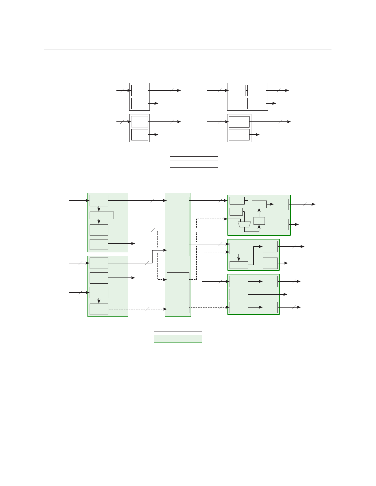
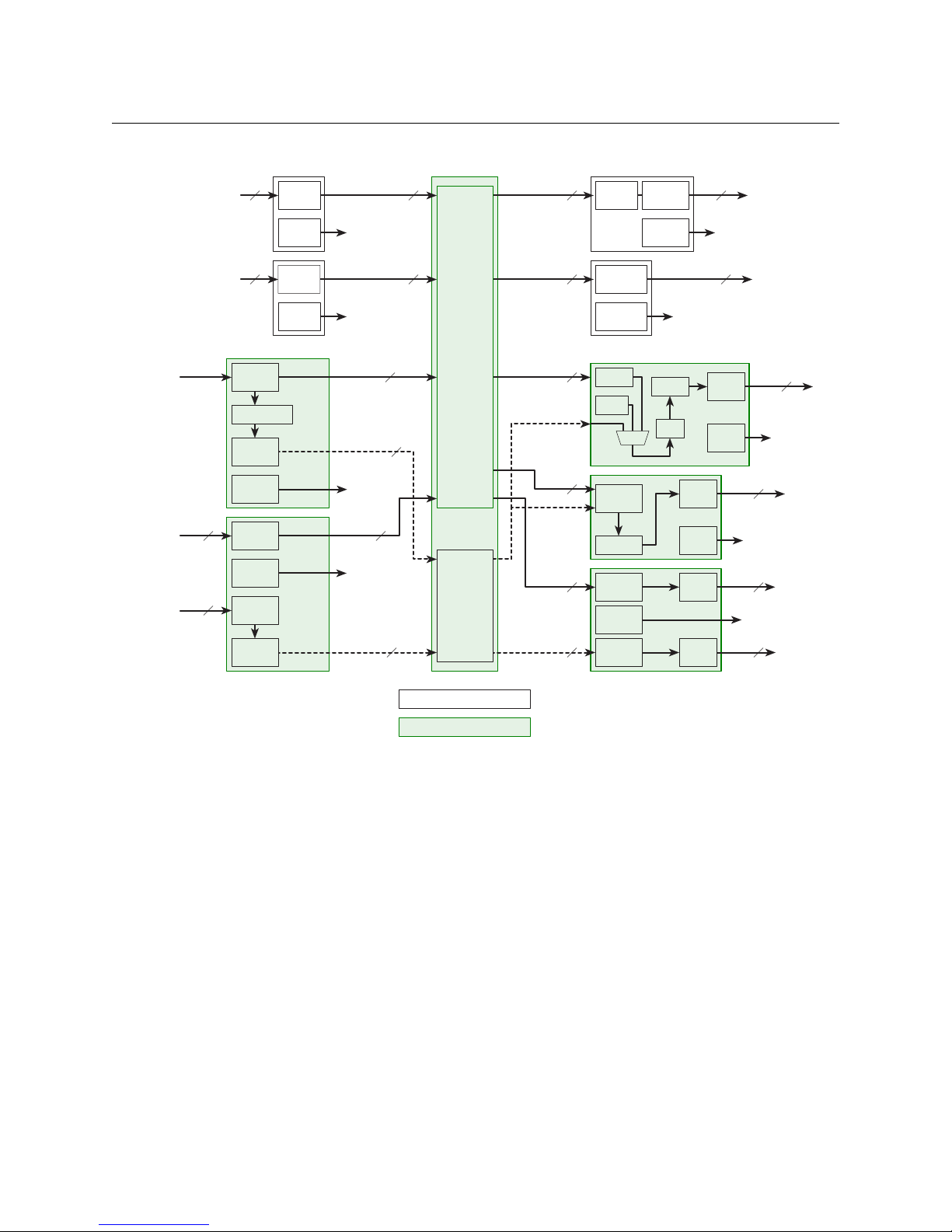
The following 3 illustrations show schematically how signals are routed in a frame with (1) only
standard I/O cards, (2) only hybrid I/O cards, and (3) both standard and hybrid I/O cards installed.
Fig. 1-1: Standard I/O Cards Only
Fig. 1-2: Hybrid Cards Only
4
NV8500 Series
Hybrid
3Gig/TDM
(MADI)
Reclocker
to Monitor
Card
MADI
Formatter
Monitor
Selector
16 video
2 MADI
Cable
Driver
Cable
Driver
16 video
Hybrid
3Gig
Monitor
Selector
Embedder
Cable
Driver
(with 256 audio
embedded)
to Monitor
Card
Reclocker
16 video
Hybrid
DEM/EMB
3Gig
Monitor
Selector
Emb.
Cable
Driver
(with 256 audio
embedded)
to Monitor
Card
Disemb.
Silence
Reclock
MUX
Reclocker
to Monitor
Card
18
Video
AES Async
(Non-Hybrid)
Standard
HD or 3Gig
Audio
Monitor
Selector
Cable
Driver
AES
Transmitter
to Monitor
Card
18
1818
Monitor
Selector
Hybrid
3Gig
Monitor
Selector
Cable
Equalizer
Video only
Disembedder
(with 128 audio
embedded)
Audio
TDM MUX
Hybrid
3Gig/TDM
(MADI)
Input Cards
Output Cards
to Monitor
Card
to Monitor
Card
MADI
Receiver
TDM
Matrix
(Audio)
Hybrid
XPT
Crosspoint
Matrix
(Video)
Monitor Cards (EM0663)
Control Cards (EM0833)
16 video
16 video
128 audio
8 video
8 video
128 audio
64 audio
Monitor
Selector
Cable
Equalizer
Audio
TDM MUX
8 video
1 MADI
Monitor
Selector
Cable
Equalizer
to Monitor
Card
Audio
Standard
HD or 3Gig
AES Async
(Non-Hybrid)
to Monitor
Card
Video
AES
Receiver
Monitor
Selector
9
9
9
9
16 video
User’s Guide
Fig. 1-3: Both Standard and Hybrid I/O Modules
5

Introduction
Overview of the Routers
Overview of the Routers
NV8500 series routers share common frame features. All I/O cards, crosspoint cards, monitor
cards, and control cards are installed through the frame front. All system connections and backplane modules are located at the rear of the frame.
The following is an overview of each router. For more information about any modules
mentioned, see the related topic:
• Inputs and Outputs on page 21
• Crosspoints on page 61
• Monitoring on page 81
• Router Control on page 75
• Power on page 111
Frame Cooling
The routers have one or more fan trays providing forced air cooling through five speedcontrolled fans. The fans draw air from the center and front of the router, through its door, and
exhaust it through the rear of the frame.
Each fan features speed control which spins the fan at the optimal rate required to ensure that a
constant temperature is maintained within the router frame. Temperature sensors at the inlet of
each fan increase or decrease the speed of the fan as required. Because the fans rotate only as
needed, fan noise is significantly reduced in partially loaded frames or in environments with
lower ambient temperatures. Maintaining a constant temperature ensures the proper operation
of router circuitry.
In the NV8144, NV8140, and the NV8280 frames, a single fan tray is located at the top of the
chassis. For the NV8576 (and NV8576-Plus) frames, there are two fan trays: one located at the top
and one located at the bottom of the frame. Each fan features two LEDs that indicate whether
the fan is receiving power and whether there is a failure. For more information, see Indicator
LEDs on page 165.
There is a removable air filter located on the inside of the door assembly. It is recommended that
filter maintenance be performed on a regular basis. For more information, see Air Flow
page 169.
on
Fuses
The NV8500 series routers have no user-serviceable fuses.
6
NV8144
NV8500 NV8500
PS8100
12345
POWER
GND
12345
48V
+
PS8100
12345
POWER
GND
12345
48V
+
Input Cards (16)Output Cards (8)
Control Cards (2)
Monitor
Card (1)
Crosspoint Cards (2) Power Supplies (2)
Fan
NV8500 Series
User’s Guide
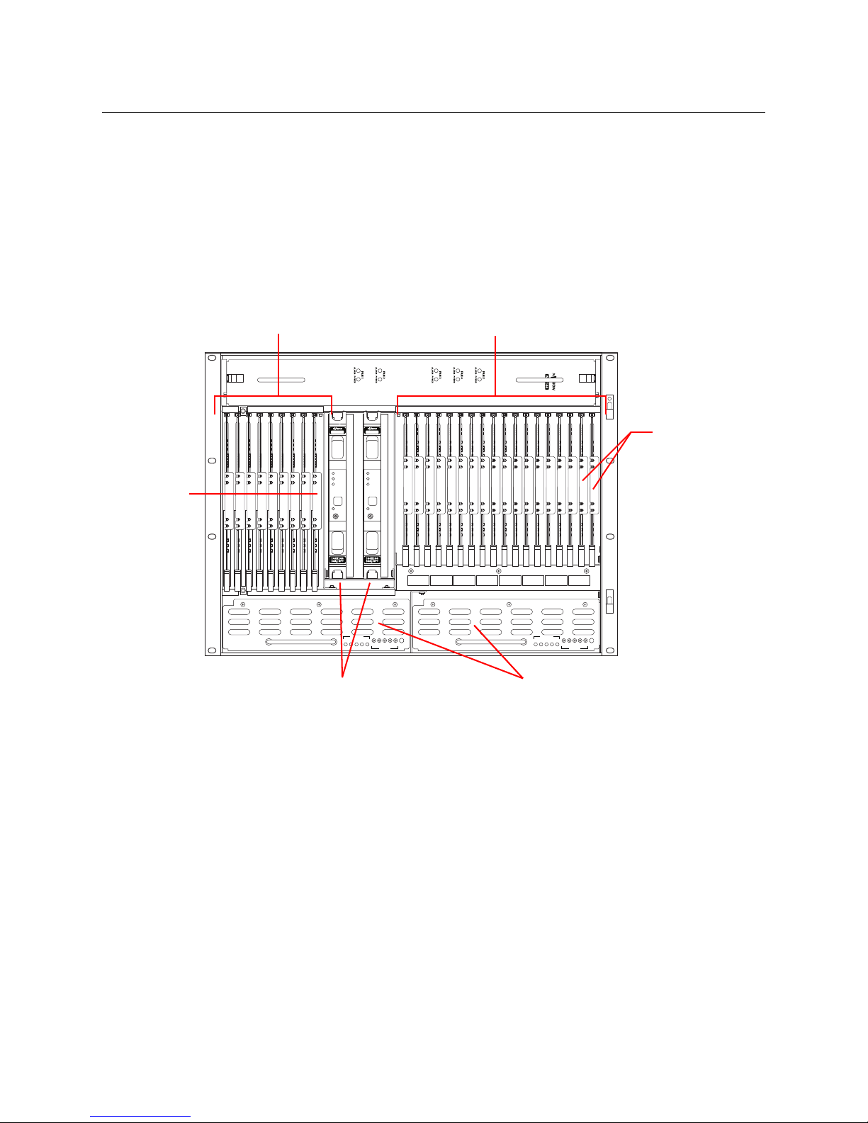
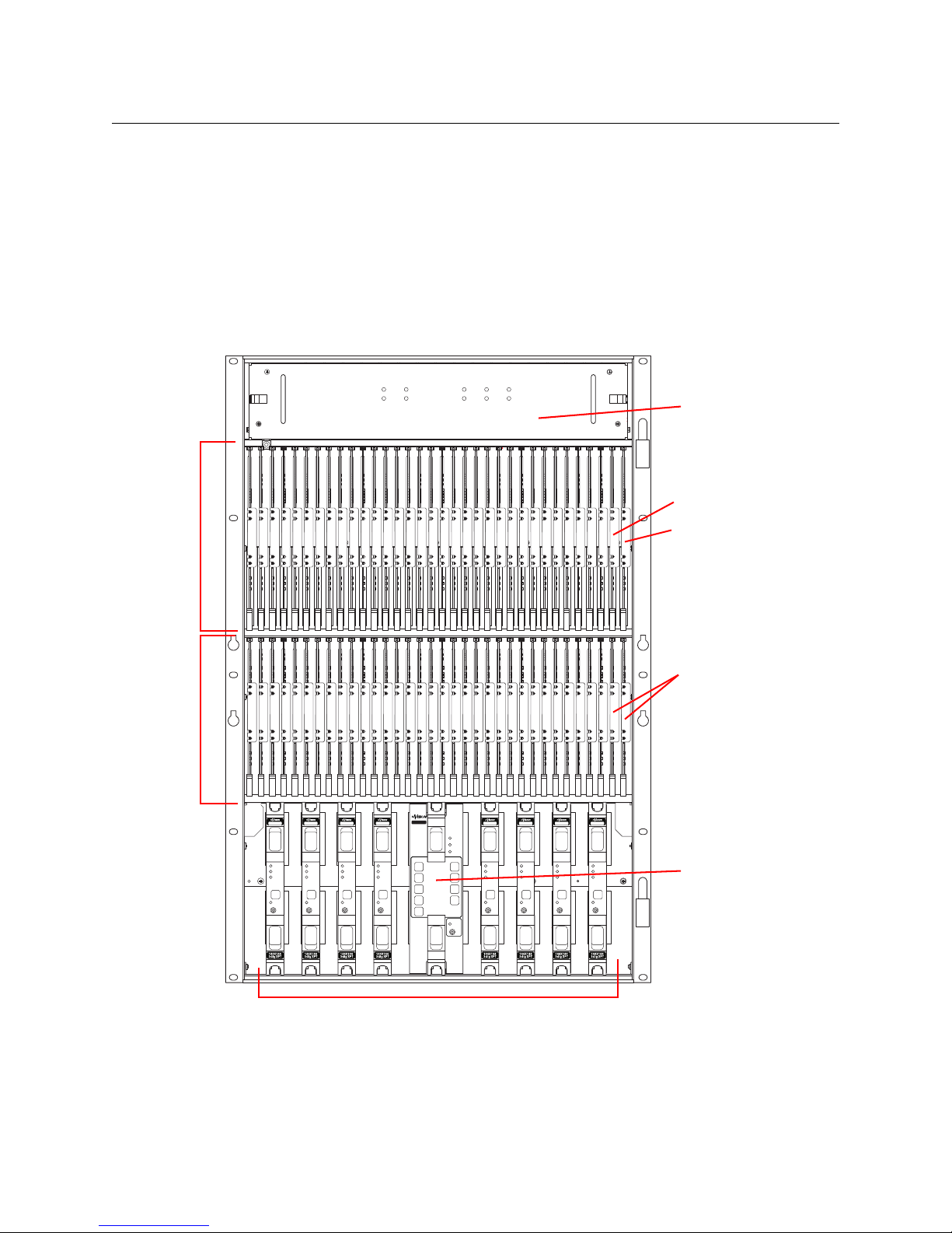
Figure 1-4 shows the front of the NV8144 (with the door removed). At the top of the frame is the
fan tray. Directly below the fan tray are card slots. On the far left are 8 output card slots. Directly
to the right of the output cards is a single slot for the monitor card. Near the center of the frame,
to the right of the output cards, are 2 crosspoint card slots. The first slot holds the primary crosspoint card. The second slot holds a second, optional 144×144 crosspoint card for redundancy.
To the right of the crosspoint card slots are 16 input card slots. To the right of the input card slots
are 2 additional slots for the primary and secondary control cards. Below the card slots, at the
bottom of the frame, are 2 bays for PS8100 power supply modules.
Fig. 1-4: NV8144 (Front View with Door Removed)
7
Introduction
DIAG (38.4 Kbaud)
CONTROL
POWER
SUPPLY
i
MONITORS
TIME CODE
NVISION AUX BUS
RTR EXP OUT
RTR EXP IN
AES REF 1
AES REF 2
VIDEO REF 2
VIDEO REF 1
RTR EXP
10/100 BT
RTR EXP
10/100 BT
CTRL 1
CTRL 2
ALARMS
CTRL 1
CTRL 2
DIAG (38.4 Kbaud)
PRI
SEC
SEC
PRI
90-130V~/180-250V~
12.5A/6.25A
50/60Hz
1125 WATTS MAX
PS1
PS2
90-130V~/180-250V~
12.5A/6.25A
50/60Hz
1125 WATTS MAX
E146905
CNTRL NO. 9K50
PROFESSIONAL
VIDEO/AUDIO
ALARMS
Output Backplanes (8)
Input Backplanes (16)
Monitor Backplane (1)
Power Connector
Power
Connector
PS Alarm
Connector
System
Connectors
Overview of the Routers
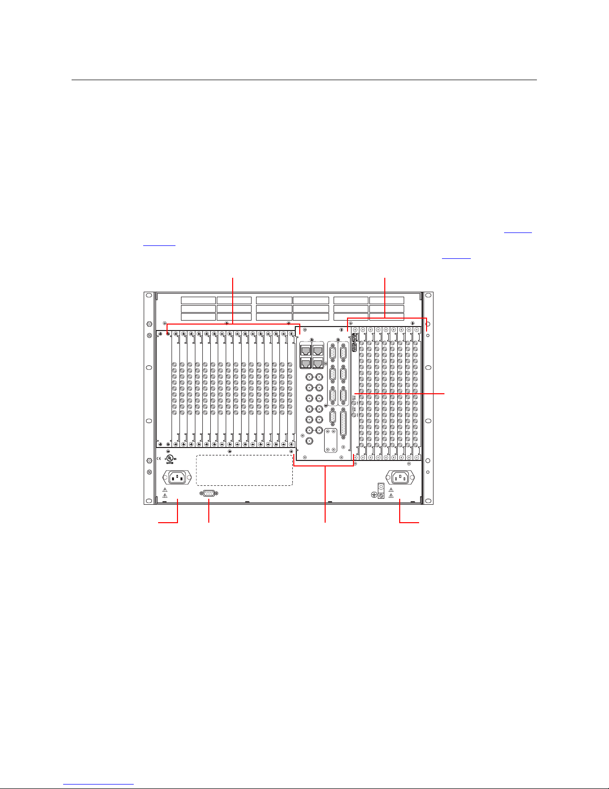
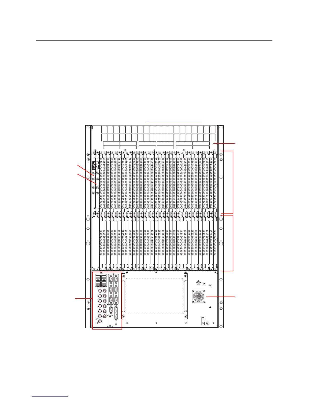
Figure 1-5 shows the rear of the NV8144. The farthest left-hand section is a blank plate that
corresponds in position to the control cards. Next to the control card plate are 16 input backplane slots. A mixture of different input cards and their backplane modules can be placed in
these slots.
The middle section contains system connections for audio reference, video reference, control
system connections, and power supply alarms.
To the right of the system connectors is one monitor backplane slot.
To the right of the monitor backplane are 8 output backplane slots. A mixture of different
output cards and their backplane modules can be placed in these slots.
At the very top of the frame is a grill for exhausting warm air dispersed by the fans. (See Frame
Cooling on page 6.) Near the bottom of the frame are two AC power connectors. To the right of
the left-hand power connection is a power supply alarm connector. (See Alarms
on page 101.)
Fig. 1-5: NV8144 (Rear View)
8
NV8140
NV8144
FAN 1
ALARM POWER
FAN 2
ALARM POWER
FAN 3
ALARM POWER
FAN 4
ALARM POWER
FAN 5
ALARM POWER
Input Cards (8)Output Cards (16)
Control Cards (2)
Redundant Crosspoint CardPower Supply
Fan
Crosspoint Cards (2)
Power Supply
Redundant Crosspoint Card
NV8500 Series
User’s Guide
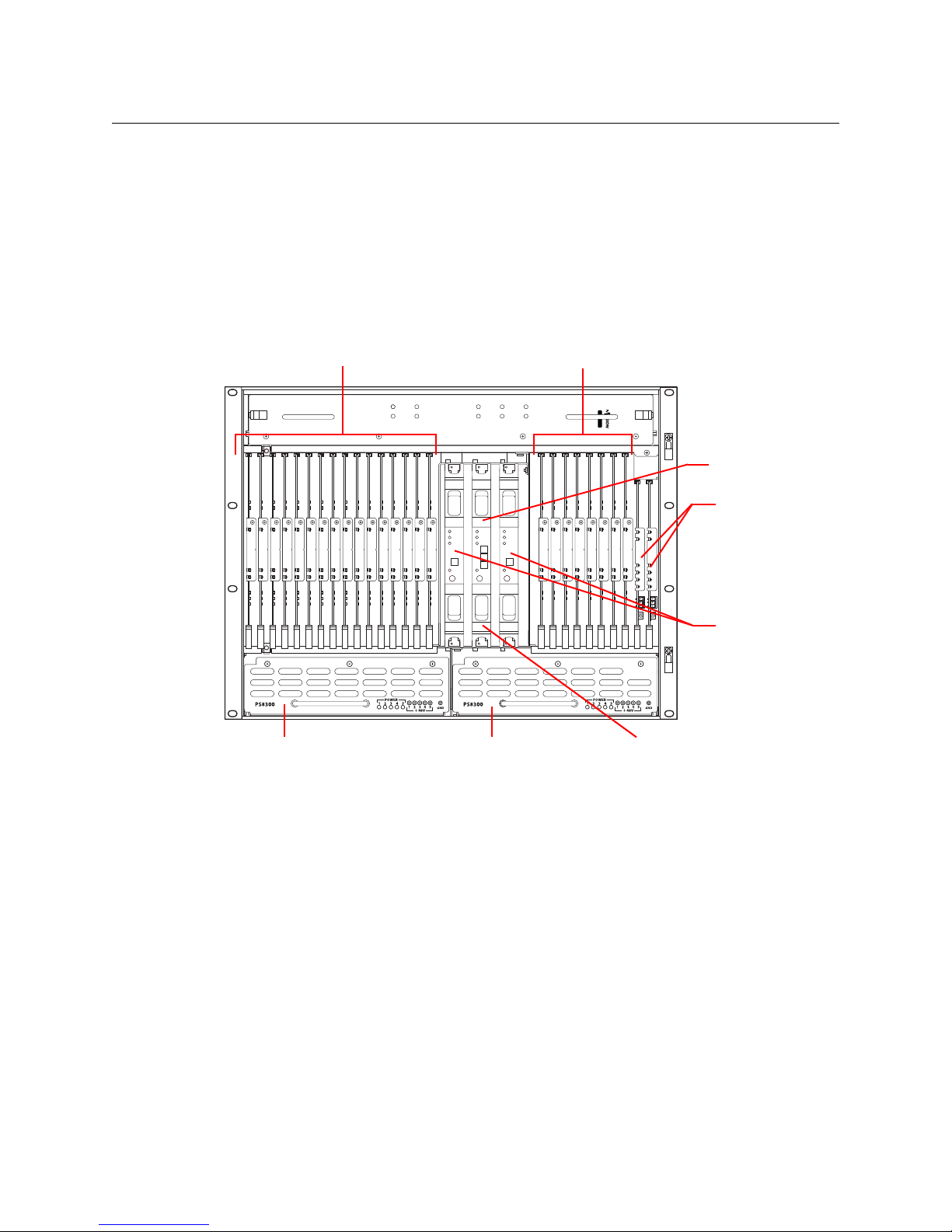
Figure 1-6 shows the front of the NV8140 (with the door removed). At the top of the frame is the
fan tray. Directly below the fan tray are card slots. On the far left are 16 output card slots. Near
the center of the frame, to the right of the output cards, are 3 crosspoint card slots. The first and
third slots hold the regular crosspoint cards. The middle slot holds a optional redundant crosspoint card.
To the right of the crosspoint card slots are 8 input card slots. To the right of the input card slots
are 2 slots for the primary and secondary control cards. Below the card slots, at the bottom of
the frame, are 2 bays for PS8300 power supply modules.
Fig. 1-6: NV8140 (Front View with Door Removed)
The NV8140 does not have a monitor card slot and does not support signal monitoring.
The NV8140 requires PS8300 power supplies, not PS 8100s.
The crosspoint card slots for the NV8140 are narrower than the crosspoint slots for the NV8144.
Do not attempt to install the older (and now obsolete) EM0799 or EM0819 crosspoint cards in
the NV8140. Physical damage will result.
Frame sync input cards are not available for the NV8140.
9
Introduction
12345678 234567810111213141516 91
POWER
SUPPLY
MONITORS
TIMECODE
NVISIONAUX BUS
RTR EXP OUT
RTR EXP IN
AES REF 1 AES REF 2
VIDEO REF 2
VIDEO REF 1
10/100BT 10/100BT
RTR EXP RTR EXP
CTRL 1
CTRL 2DIAG (38.4 Kbaud)
CTRL 1
CTRL 2DIAG (38.4 Kbaud)
ALARMS
CONTROL
PRI PRI
SEC
SEC
100 - 240V~
15A / 7.5A
50 / 60Hz
100 - 240V~
15A / 7.5A
50 / 60Hz
Output Backplanes (16)
Input Backplanes (8)
Power Connector
Power
Connector
PS Alarm
Connector
System
Connectors
Overview of the Routers
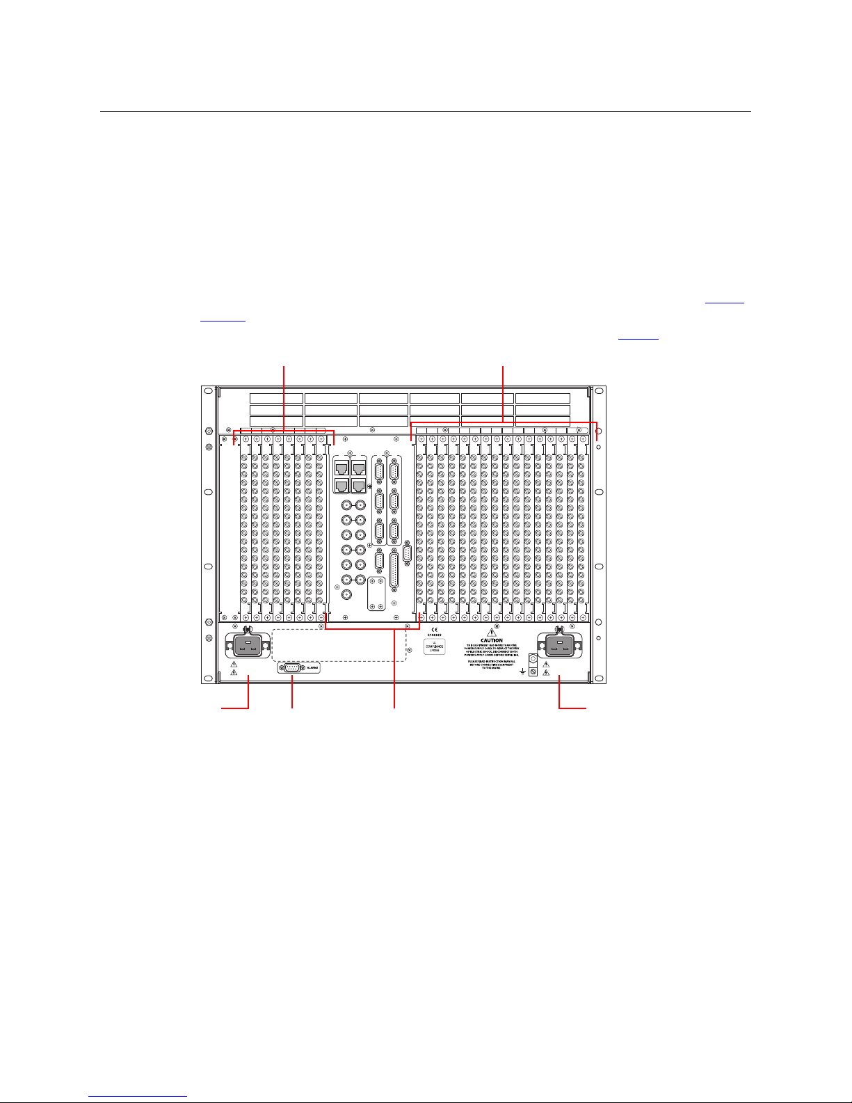
Figure 1-7 shows the rear of the NV8140. The farthest left-hand section is a blank plate that
corresponds in position to the control cards. Next to the control card plate are 8 input backplane
slots. A mixture of different input cards and their backplane modules can be placed in these
slots.
The middle section contains system connections for audio reference, video reference, control
system connections, and power supply alarms.
To the right of the monitor backplane are 16 output backplane slots. A mixture of different
output cards and their backplane modules can be placed in these slots.
At the very top of the frame is a grill for exhausting warm air dispersed by the fans. (See Frame
Cooling on page 6.) Near the bottom of the frame are two AC power connectors. To the right of
the left-hand power connection is a power supply alarm connector. (See Alarms
on page 101.)
Fig. 1-7: NV8140 (Rear View)
The NV8140 uses PS8300 power supplies, not PS8100s. It has two C19 power connectors and
require 20A plant lines. The cable supplied in North America has a NEMA L5-20P connector at
the other end. For customers outside North America, we ship these power cords with the NEMA
end cut off.
The input backplane modules of the NV8140 have 18 connectors, not 9 as for the other routers.
10
NV8280
NV8280
144 X 144
3Gig
Redundant
XPT
STANDBY
PATH
LITE
ALARM
ACTIVE
POWER
REDUNDANT OPERATION
1
7
2
8
3
9
4
10
NV8500 NV8500NV8500 NV8500 NV8500 NV8500 NV8500 NV8500 NV8500
Output
Cards (32)
Input
Cards (32)
Control Cards (2)
Crosspoint Cards (8)
Fan Tray
Output Monitor Card
Redundant
Crosspoint
Input Monitor Card
NV8500 Series
User’s Guide
Figure 1-8 shows the front of the NV8280 (with the door removed). At the top of the frame is the
fan tray. Directly below are 32 output cards slots. Below the output cards are 32 input card slots.
To the far right of the output card slots are two additional slots for monitor cards. Similarly, to
the far right of the input card slots are two additional slots for the primary control card and
secondary control card.
Below the input card slots, at the bottom of the frame, are 10 crosspoint card slots. The middle 2
crosspoint card slots are for an optional redundant crosspoint. The other 8 slots are for crosspoint cards.
Fig. 1-8: NV8280 (Front View with Door Removed)
11
Introduction
10/100 BT
RTR EXP
10/100 BT
RTR EXP
VIDEO REF 1
PRI
SEC
CONTROL
CTRL 1
CTRL 2
CTRL 1
CTRL 2
DIAG (38.4 Kbaud)
DIAG (38.4 Kbaud)
VIDEO REF 2
AES REF 1
AES REF 2
RTR EXP IN
ALARMS
RTR EXP OUT
NVISION AUX BUS
POWER
SUPPLY
MONITORS
TIME CODE
E146905
POWER INPUT
PRI
SEC
Output Backplanes (32)
Input Backplanes (32)
Output Monitor
Backplane
System
Connectors
Power Connector
Fan
Input Monitor
Backplane
Overview of the Routers
Figure 1-9 shows the rear of the NV8280. At the very top of the frame is a grill for exhausting
warm air dispersed by the fans. Directly below the fan tray, starting from the left, are 2 monitor
backplane slots. To the right of the monitor backplane slots are 32 output backplane slots. A
mixture of different output cards and their backplane modules can be placed in these slots.
Directly below the output slots, starting from the left, is a blank back plate that corresponds in
position to the control cards. Next to the blank back plate are 32 input backplane slots. A
mixture of different input cards and their backplane modules can be placed in these slots.
At the very bottom of the frame, on the left-hand side, are system connections for audio reference and video reference, control system connectors, and alarm connectors. On the right-hand
side is a single power connector that connects the router to an NV8300 power supply frame. For
information about the NV8300, see Power Supply Distribution
on page 113.
Fig. 1-9: NV8280 (Rear View)
12

NV8576
NV8500 Series
User’s Guide
Figure 1-10, next page, shows the front of the NV8576.
The router is divided into three regions: upper, middle, and lower. The upper and lower regions
each have 32 slots for output cards and 32 slots for input cards. The NV8576 thus has a total of
64 output card slots and 64 inputs card slots. Cards in the lower region of the frame are installed
upside down (i.e., rotated 180° with respect to those in the upper region).
In the upper region, to the far right of the output card slots, are two monitor card slots. Similarly,
to the far right of the input card slots are two slots for the primary control card and the
secondary control card. The lower region has two more monitor card slots, at the far left of the
output cards. (The lower region does not have control cards.)
In the middle region are 10 slots for crosspoint cards. The middle 2 crosspoint card slots hold an
optional redundant crosspoint. The remaining 8 slots are for crosspoint cards.
13
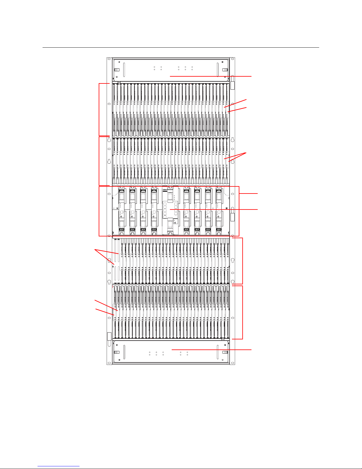
Introduction
NV8280
144 X 144
3Gig
Redundant
XPT
STANDBY
PATH
LITE
ALARM
ACTIV
POWE
REDUNDANT OPERATION
1
7
2
8
3
9
4
10
NV8500 NV8500NV8500 NV8500 NV8500 NV8500 NV8500 NV8500 NV8500
Output
Cards (32)
Input
Cards (32)
Control Cards (2)
Crosspoint Cards (8)
Fan Tray
Input Monitor Card
Redundant
Crosspoint
Fan Tray
Output
Cards (32)
Input
Cards (32)
Input Monitor Card
Unused
slots (2)
Output Monitor Card
Output Monitor Card
Overview of the Routers
Fig. 1-10: NV8576 (Front View with Door Removed)
Figure 1-11, following, shows the rear of the NV8576. The upper and lower regions each have a
32 output slots and 32 input slots, for a total of 64 output slots and 64 input slots.
In the upper region, to the far left of the output backplanes are two additional backplanes for
monitoring signals. Likewise, in the lower region, to the far right of the input backplanes are two
more backplanes for monitoring signals.
14
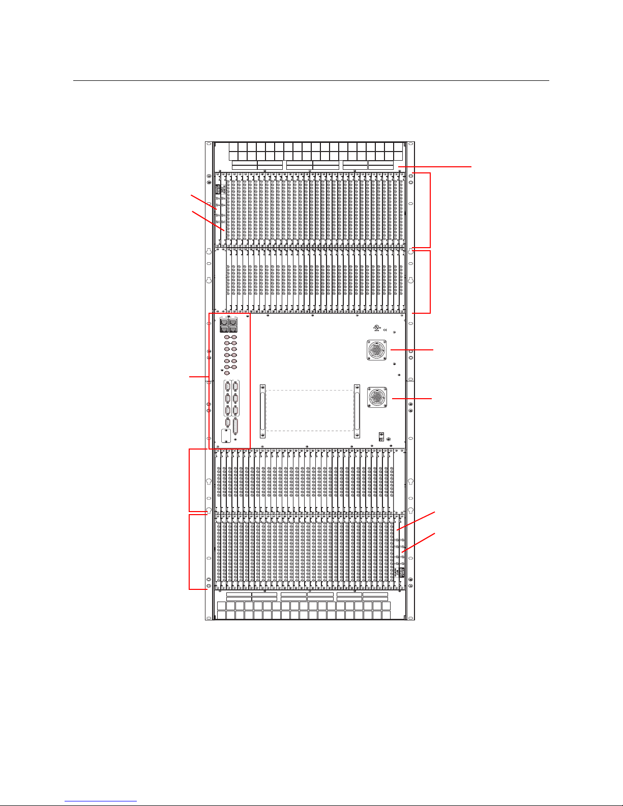
NV8500 Series
10/100 BT
RTR EXP
10/100 BT
RTR EXP
VIDEO REF 1
PRI
SEC
CONTROL
CTRL 1
CTRL 2
CTRL 1
CTRL 2
DIAG (38.4 Kbaud)
DIAG (38.4 Kbaud)
VIDEO REF 2
AES REF 1
AES REF 2
RTR EXP IN
ALARMS
RTR EXP OUT
NVISION AUX BUS
POWER
SUPPLY
MONITORS
TIME CODE
E146905
POWER INPUT
PRI
SEC
CONTROL
POWER INPUT
Output Backplanes (32)
Input Backplanes (32)
Output Monitor Backplane
System
Connectors
Power Connector 1
Fan
Power Connector 2
Output
Backplanes
(32)
Input
Backplanes
(32)
Input Monitor Backplane
Output Monitor Backplane
Input Monitor Backplane
User’s Guide
In the center of the frame, on the left-hand side, are system connections for audio and video
references, control systems, and alarms. On the right-hand side are two power connections for
connecting the router to two NV8300 power supply frames.
Fig. 1-11: NV8576 (Rear View)
15

Introduction
Preparing for Installation
Expanded NV8576-Plus
The expanded NV8576-Plus router comprises two 32RU frames that have the same structure as
the NV8576 frames. Please refer to figures 1-10 and 1-11, preceding, to see NV8576-Plus frame
structure.
Note that the expanded NV8576-Plus, consisting of 2 frames, will require 4 NV8300 power
supply frames, two for each frame.
The NV8576-Plus, of course, will be populated with expansion output cards and backplanes
instead of regular output cards and backplanes. Expansion output cards in one frame connect
to matching expansion output cards in the other frame. An expansion output card in the first
frame must match the expansion output card to which it is connected in the second frame in
type and position. See Expansion I/O Cards
NV8576-Plus (Stand-Alone)
A stand-alone NV8576-Plus is a single 32RU frame that have the same structure as the NV8576
frame. Please refer to figures 1-10 and 1-11, preceding to see the stand-alone NV8576-Plus
frame structure.
The stand-alone NV8576-Plus requires 2 NV8300 power supply frames.
The stand-alone NV8576-Plus, of course, will be populated with expansion output cards.
Because there is only one frame, expansion cables are not used.
on page 94 for details about matching card types.
Preparing for Installation
Before you set up the router, be sure to review the information in this section.
When your products arrive, immediately inspect the shipping container. If the container is
damaged, unpack and inspect the contents. If the contents are damaged, notify the carrier
immediately.
When unpacking the shipping container, look for the packing slip and compare it against the
contents to verify that everything ordered was received. If anything is missing (or if equipment is
damaged unrelated to shipping), please contact Miranda.
Your shipment does not contain mounting racks, network cables, video cables, mounting
screws, or grounding wire. If you have ordered an NV8280, NV8576, or NV8576-Plus, included in
the shipment will be one or more NV8300 external power supply frames.
Shipments of the NV8576 and NV8576-Plus also include a rack-mounting kit, including a jack,
lifting handles, and instructions.
You will need the following items for installation:
A computer running Windows
required for installing the Miranda Router Configurator and other configuration software.
Computer hardware requirements:
CD drive.
RS-232 serial COM port (DE9) capable of operating at 38.4Baud.
2000, Windows® XP Professional, or Windows® 7. This is
®
10BaseT or 10/100BaseT (preferred) Ethernet port.
16
 Loading...