

Page 1

NV8500 Series
Hybrid Digital Video/Audio Routers
User’s Guide
UG0034-10
24 Nov 2014
Page 2

Copyright & Trademark Notice
Copyright © 2014 Grass Valley. All rights reserved.
Belden, Belden Sending All The Right Signals, and the Belden logo are trademarks or
registered trademarks of Belden Inc. or its affiliated companies in the United States and
other jurisdictions. Grass Valley, NVISION, and NV8500 Series are trademarks or registered
trademarks of Grass Valley. Belden Inc., Grass Valley, and other parties may also have
trademark rights in other terms used herein.
Terms and Conditions
Please read the following terms and conditions carefully. By using NV8500 Series
documentation, you agree to the following terms and conditions.
Grass Valley hereby grants permission and license to owners of NV8500 Series routers to use
their product manuals for their own internal business use. Manuals for Grass Valley products
may not be reproduced or transmitted in any form or by any means, electronic or
mechanical, including photocopying and recording, for any purpose unless specifically
authorized in writing by Grass Valley.
A Grass Valley manual may have been revised to reflect changes made to the product during
its manufacturing life. Thus, different versions of a manual may exist for any given product.
Care should be taken to ensure that one obtains the proper manual version for a specific
product serial number.
Information in this document is subject to change without notice and does not represent a
commitment on the part of Grass Valley.
Warranty information is available in the support section of the Grass Valley web site
(www.grassvalley.com).
Title NV8500 Series Routers User’s Guide
Part Number UG0034-10
Revision 3.5 (24 Nov 14)
ii
Page 3
Change History
Rev. Date ECO Description Approved
1.0 21 Apr 09 15703 Initial release. DM, DC
2.0 10 Oct 09 16114 Incorporates material for the NV8576, NV8280, and
2.1 12 Jan 10 16272 Minor corrections, page 74, 76. DM, DC
2.2 27 Mar 10 16912 Changes to SFP modules; UniConfig connections;
2.3 01 Feb 11 17412 Address signal numbering for backplanes. Updated
3.0 13 Apr 12 18179 Hybrid cards and functionality. NV8300 and PS8300.
3.1 25 Apr 13 18826 Added DEM/EMB cards, NV8140 HD input card; misc.
3.2 03 Feb 14 19133 Conforms to firmware release 3.5.2. D.Cox
3.3 15 May 14 19241 Fixes for alarm connections.
3.4 11 Nov 14 19356 Added IP gateway cards. D.Cox
3.5 24 Nov 14 19357 Minor corrections. D.Cox
NV8500 Series Routers
User’s Guide
DM, DC
NV8144 with corrections and new information.
DEM, RH, BH
Added signal numbering for backplanes. Changed
WECO to terminal block. Added monitoring
functions for NV8144.
DEM, RH, BH
for new monitor backplane for NV8144. Address
hybrid cards and functionality, NV8300 and PS8300,
changes to I/O cards. Removed NV8280-Plus. New
port numbering.
D.Cox
Changes to I/O cards. Removal of NV8280-Plus.
Connector numbering.
Expansion hybrid cards. Expansion connections.
Hybrid de-embedders and embedders support
SMPTE 274M and 296M; Detection of Dolby E, MADI
DIP switch. Reorganization of manual
D.Cox
changes
D.Cox
Phase 3 of frame sync. M3 cards, rears, cables.
Safety Compliance
Korean Compliance (KCC) Statement
이 기기는 업무용 (A 급 ) 전자파적합기기로서 판
매자
또는 사용자는 이 점을 주의하시기 바라
며
, 가정외의 지역에서 사용하는 것을 목적으로
합니다
Please note this is a Class A device. Sellers or users need to take note of this and should not
use this equipment in a domestic environment.
.
KCC-REM-XEI-NV8500
급 기기
A
( 업무용 방송통신 기자재 )
Class A Equipment
(Commercial Broadcasting & Communication Equipment)
iii
Page 4

FCC Statement
This equipment has been tested and found to comply with the limits for a Class A digital
device, pursuant to part 15 of the FCC Rules. These limits are designed to provide reasonable
protection against harmful interference when the equipment is operated in a commercial
environment. This equipment generates, uses, and can radiate radio frequency energy and,
if not installed and used in accordance with the instruction manual, may cause harmful
interference to radio communications. Operation of this equipment in a residential area is
likely to cause harmful interference in which case the user will be required to correct the
interference at his own expense.
Declaration of Conformance (CE)
All of the equipment described in this manual has been designed to conform with the
required safety and emissions standards of the European Community. Products tested and
verified to meet these standards are marked as required by law with the CE mark.
When shipped into member countries of the European Community, this equipment is
accompanied by authentic copies of original Declarations of Conformance on file in the
Grass Valley offices in Grass Valley, California USA.
Software License Agreement and Warranty Information
Contact Grass Valley for details on the software license agreement and product warranty.
iv
Page 5

Important Safeguards and Notices
This section provides important safety guidelines for operators and service personnel.
Specific warnings and cautions appear throughout the manual where they apply. Please
read and follow this important information, especially those instructions related to the risk
of electric shock or injury to persons.
WAR NIN G
Any instructions in this manual that require opening the equipment cover or enclosure are
for use by qualified service personnel only. To reduce the risk of electric shock, do not
perform any service other than that contained in the operating instructions unless you are
qualified to do so.
Restriction on Hazardous Substances (RoHs)
Grass Valley is in compliance with EU Directive RoHS 2002/95/EC governing the restricted
use of certain hazardous substances and materials in products and in our manufacturing
processes.
Grass Valley has a substantial program in place for RoHS compliance that includes significant
investment in our manufacturing process, and a migration of Grass Valley product electronic
components and structural materials to RoHS compliance.
It is our objective at Grass Valley to maintain compliance with all relevant environmental and
product regulatory requirements. Detailed information on specific products or on the RoHS
program at Grass Valley is available from Grass Valley Customer Support at
1-800-719-1900 (toll-free) or
1-530-265-1000 (outside the U.S.).
NV8500 Series Routers
User’s Guide
v
Page 6
Symbols and Their Meanings
The lightning flash with arrowhead symbol within an equilateral triangle alerts the
user to the presence of dangerous voltages within the product’s enclosure that
may be of sufficient magnitude to constitute a risk of electric shock to persons.
The exclamation point within an equilateral triangle alerts the user to the presence
of important operating and maintenance/service instructions.
The Ground symbol represents a protective grounding terminal. Such a terminal
must be connected to earth ground prior to making any other connections to the
equipment.
The fuse symbol indicates that the fuse referenced in the text must be replaced
with one having the ratings indicated.
The presence of this symbol in or on Grass Valley equipment means that it has been
designed, tested and certified as complying with applicable Underwriter’s
Laboratory (USA) regulations and recommendations.
The presence of this symbol in or on Grass Valley equipment means that it has been
designed, tested and certified as essentially complying with all applicable
European Union (CE) regulations and recommendations.
General Warnings
A warning indicates a possible hazard to personnel which may cause injury or death.
Observe the following general warnings when using or working on this equipment:
• Heed all warnings on the unit and in the operating instructions.
• Do not use this equipment in or near water.
• This equipment is grounded through the grounding conductor of the power cord. To
avoid electrical shock, plug the power cord into a properly wired receptacle before connecting the equipment inputs or outputs.
• Route power cords and other cables so they are not likely to be damaged.
• Disconnect power before cleaning the equipment. Do not use liquid or aerosol cleaners; use only a damp cloth.
• Dangerous voltages may exist at several points in this equipment. To avoid injury, do
not touch exposed connections and components while power is on.
• Do not wear rings or wristwatches when troubleshooting high current circuits such as
the power supplies.
vi
Page 7

NV8500 Series Routers
User’s Guide
• To avoid fire hazard, use only the specified fuse(s) with the correct type number, voltage
and current ratings as referenced in the appropriate locations in the service instructions or on the equipment. Always refer fuse replacements to qualified service personnel.
• To avoid explosion, do not operate this equipment in an explosive atmosphere.
• Have qualified service personnel perform safety checks after any service.
General Cautions
A caution indicates a possible hazard to equipment that could result in equipment damage.
Observe the following cautions when operating or working on this equipment:
• When installing this equipment, do not attach the power cord to building surfaces.
• To prevent damage to equipment when replacing fuses, locate and correct the problem
that caused the fuse to blow before re-applying power.
• Use only the specified replacement parts.
• Follow static precautions at all times when handling this equipment.
• This product should only be powered as described in the manual. To prevent equipment damage, select the proper line voltage on the power supply(ies) as described in
the installation documentation.
• To prevent damage to the equipment, read the instructions in the equipment manual
for proper input voltage range selection.
• Some products include a backup battery. There is a risk of explosion if the battery is
replaced by a battery of an incorrect type. Dispose of batteries according to instructions.
• Products that have (1) no on/off switch and (2) use an external power supply must be
installed in proximity to a main power outlet that is easily accessible.
• To reduce the risk of electrical shock, plug each power supply cord into a separate
branch circuit having a separate service ground.
vii
Page 8

viii
Page 9

Table of Contents
1 Introduction . . . . . . . . . . . . . . . . . . . . . . . . . . . . . . . . . . . . . . . . . . . 1
About the NV8500 Series Routers . . . . . . . . . . . . . . . . . . . . . . . . . . . . . . . . . . . . . . . . . . . . . . . . . . . . . . . . . . . . . . . 1
Signal Types and Rates . . . . . . . . . . . . . . . . . . . . . . . . . . . . . . . . . . . . . . . . . . . . . . . . . . . . . . . . . . . . . . . . . . . . . 2
Standard vs. Hybrid . . . . . . . . . . . . . . . . . . . . . . . . . . . . . . . . . . . . . . . . . . . . . . . . . . . . . . . . . . . . . . . . . . . . . . . . 3
Overview of the Routers. . . . . . . . . . . . . . . . . . . . . . . . . . . . . . . . . . . . . . . . . . . . . . . . . . . . . . . . . . . . . . . . . . . . . . . . . 6
Frame Cooling . . . . . . . . . . . . . . . . . . . . . . . . . . . . . . . . . . . . . . . . . . . . . . . . . . . . . . . . . . . . . . . . . . . . . . . . . . . . . 6
Fuses . . . . . . . . . . . . . . . . . . . . . . . . . . . . . . . . . . . . . . . . . . . . . . . . . . . . . . . . . . . . . . . . . . . . . . . . . . . . . . . . . . . . . . 6
NV8144 . . . . . . . . . . . . . . . . . . . . . . . . . . . . . . . . . . . . . . . . . . . . . . . . . . . . . . . . . . . . . . . . . . . . . . . . . . . . . . . . . . . . 7
NV8140 . . . . . . . . . . . . . . . . . . . . . . . . . . . . . . . . . . . . . . . . . . . . . . . . . . . . . . . . . . . . . . . . . . . . . . . . . . . . . . . . . . . . 9
NV8280 . . . . . . . . . . . . . . . . . . . . . . . . . . . . . . . . . . . . . . . . . . . . . . . . . . . . . . . . . . . . . . . . . . . . . . . . . . . . . . . . . . . 11
NV8576 . . . . . . . . . . . . . . . . . . . . . . . . . . . . . . . . . . . . . . . . . . . . . . . . . . . . . . . . . . . . . . . . . . . . . . . . . . . . . . . . . . . 13
Expanded NV8576-Plus . . . . . . . . . . . . . . . . . . . . . . . . . . . . . . . . . . . . . . . . . . . . . . . . . . . . . . . . . . . . . . . . . . . 16
NV8576-Plus (Stand-Alone) . . . . . . . . . . . . . . . . . . . . . . . . . . . . . . . . . . . . . . . . . . . . . . . . . . . . . . . . . . . . . . . 16
Preparing for Installation . . . . . . . . . . . . . . . . . . . . . . . . . . . . . . . . . . . . . . . . . . . . . . . . . . . . . . . . . . . . . . . . . . . . . . . 16
Installation Steps . . . . . . . . . . . . . . . . . . . . . . . . . . . . . . . . . . . . . . . . . . . . . . . . . . . . . . . . . . . . . . . . . . . . . . . . . . 17
Rack Mount . . . . . . . . . . . . . . . . . . . . . . . . . . . . . . . . . . . . . . . . . . . . . . . . . . . . . . . . . . . . . . . . . . . . . . . . . . . . . . . . . . . . 18
To Rack Mount the Router . . . . . . . . . . . . . . . . . . . . . . . . . . . . . . . . . . . . . . . . . . . . . . . . . . . . . . . . . . . . . . . . . 19
2 Inputs and Outputs . . . . . . . . . . . . . . . . . . . . . . . . . . . . . . . . . . . . 21
Types of Input and Output . . . . . . . . . . . . . . . . . . . . . . . . . . . . . . . . . . . . . . . . . . . . . . . . . . . . . . . . . . . . . . . . . . . . . 21
Backplanes. . . . . . . . . . . . . . . . . . . . . . . . . . . . . . . . . . . . . . . . . . . . . . . . . . . . . . . . . . . . . . . . . . . . . . . . . . . . . . . . 22
Backplanes with Fiber Optic Connectors. . . . . . . . . . . . . . . . . . . . . . . . . . . . . . . . . . . . . . . . . . . . . . . 23
Backplanes with Coax Connectors. . . . . . . . . . . . . . . . . . . . . . . . . . . . . . . . . . . . . . . . . . . . . . . . . . . . . 24
Backplanes with WECO Connectors . . . . . . . . . . . . . . . . . . . . . . . . . . . . . . . . . . . . . . . . . . . . . . . . . . . 24
Backplanes for IP Gateway Cards . . . . . . . . . . . . . . . . . . . . . . . . . . . . . . . . . . . . . . . . . . . . . . . . . . . . . . 25
Backplanes for Hybrid Cards . . . . . . . . . . . . . . . . . . . . . . . . . . . . . . . . . . . . . . . . . . . . . . . . . . . . . . . . . . 25
Signal Numbering . . . . . . . . . . . . . . . . . . . . . . . . . . . . . . . . . . . . . . . . . . . . . . . . . . . . . . . . . . . . . . . . . . . . . . . . . 27
I/O Space. . . . . . . . . . . . . . . . . . . . . . . . . . . . . . . . . . . . . . . . . . . . . . . . . . . . . . . . . . . . . . . . . . . . . . . . . . . . . 28
Disembedder Input. . . . . . . . . . . . . . . . . . . . . . . . . . . . . . . . . . . . . . . . . . . . . . . . . . . . . . . . . . . . . . . . . . . 31
Embedder Output . . . . . . . . . . . . . . . . . . . . . . . . . . . . . . . . . . . . . . . . . . . . . . . . . . . . . . . . . . . . . . . . . . . . 32
IP Gateway Cards . . . . . . . . . . . . . . . . . . . . . . . . . . . . . . . . . . . . . . . . . . . . . . . . . . . . . . . . . . . . . . . . . . . . . 33
3Gig/TDM Input . . . . . . . . . . . . . . . . . . . . . . . . . . . . . . . . . . . . . . . . . . . . . . . . . . . . . . . . . . . . . . . . . . . . . . 34
3Gig/TDM Output . . . . . . . . . . . . . . . . . . . . . . . . . . . . . . . . . . . . . . . . . . . . . . . . . . . . . . . . . . . . . . . . . . . . 34
Embedded Group Control . . . . . . . . . . . . . . . . . . . . . . . . . . . . . . . . . . . . . . . . . . . . . . . . . . . . . . . . . . . . . . . . . 35
Slot Numbering . . . . . . . . . . . . . . . . . . . . . . . . . . . . . . . . . . . . . . . . . . . . . . . . . . . . . . . . . . . . . . . . . . . . . . . . . . . . . . . . 36
Physical Slot Ordering . . . . . . . . . . . . . . . . . . . . . . . . . . . . . . . . . . . . . . . . . . . . . . . . . . . . . . . . . . . . . . . . . . . . . 36
Slot Order for Port Numbering . . . . . . . . . . . . . . . . . . . . . . . . . . . . . . . . . . . . . . . . . . . . . . . . . . . . . . . . . . . . . 37
NV8140, NV8144 or NV820. . . . . . . . . . . . . . . . . . . . . . . . . . . . . . . . . . . . . . . . . . . . . . . . . . . . . . . . . . . . 37
NV8576 . . . . . . . . . . . . . . . . . . . . . . . . . . . . . . . . . . . . . . . . . . . . . . . . . . . . . . . . . . . . . . . . . . . . . . . . . . . . . . 37
NV8576-Plus . . . . . . . . . . . . . . . . . . . . . . . . . . . . . . . . . . . . . . . . . . . . . . . . . . . . . . . . . . . . . . . . . . . . . . . . . 38
I/O Backplanes . . . . . . . . . . . . . . . . . . . . . . . . . . . . . . . . . . . . . . . . . . . . . . . . . . . . . . . . . . . . . . . . . . . . . . . . . . . . . . . . . 39
Installing I/O Backplanes . . . . . . . . . . . . . . . . . . . . . . . . . . . . . . . . . . . . . . . . . . . . . . . . . . . . . . . . . . . . . . . . . . 41
To Install an I/O Backplane . . . . . . . . . . . . . . . . . . . . . . . . . . . . . . . . . . . . . . . . . . . . . . . . . . . . . . . . . . . . 41
Backplanes Having SFP Modules . . . . . . . . . . . . . . . . . . . . . . . . . . . . . . . . . . . . . . . . . . . . . . . . . . . . . . . . . . . 42
IP Gateway Backplanes . . . . . . . . . . . . . . . . . . . . . . . . . . . . . . . . . . . . . . . . . . . . . . . . . . . . . . . . . . . . . . . 42
Other Backplanes with SFP Modules . . . . . . . . . . . . . . . . . . . . . . . . . . . . . . . . . . . . . . . . . . . . . . . . . . 44
SFP Modules in NV8576 Frames . . . . . . . . . . . . . . . . . . . . . . . . . . . . . . . . . . . . . . . . . . . . . . . . . . . . . . . 44
ix
Page 10

Table of Contents
SFP Modules in NV8576-Plus Frames . . . . . . . . . . . . . . . . . . . . . . . . . . . . . . . . . . . . . . . . . . . . . . . . . . 45
SFP Modules in NV8280, NV8140, and NV8144 Frames . . . . . . . . . . . . . . . . . . . . . . . . . . . . . . . . . 46
I/O Cards . . . . . . . . . . . . . . . . . . . . . . . . . . . . . . . . . . . . . . . . . . . . . . . . . . . . . . . . . . . . . . . . . . . . . . . . . . . . . . . . . . . . . . 46
AES Async. . . . . . . . . . . . . . . . . . . . . . . . . . . . . . . . . . . . . . . . . . . . . . . . . . . . . . . . . . . . . . . . . . . . . . . . . . . . . . . . . 48
Input. . . . . . . . . . . . . . . . . . . . . . . . . . . . . . . . . . . . . . . . . . . . . . . . . . . . . . . . . . . . . . . . . . . . . . . . . . . . . . . . . 48
Output . . . . . . . . . . . . . . . . . . . . . . . . . . . . . . . . . . . . . . . . . . . . . . . . . . . . . . . . . . . . . . . . . . . . . . . . . . . . . . . 48
HD or 3Gig (Standard) . . . . . . . . . . . . . . . . . . . . . . . . . . . . . . . . . . . . . . . . . . . . . . . . . . . . . . . . . . . . . . . . . . . . . 49
Input. . . . . . . . . . . . . . . . . . . . . . . . . . . . . . . . . . . . . . . . . . . . . . . . . . . . . . . . . . . . . . . . . . . . . . . . . . . . . . . . . 49
Output . . . . . . . . . . . . . . . . . . . . . . . . . . . . . . . . . . . . . . . . . . . . . . . . . . . . . . . . . . . . . . . . . . . . . . . . . . . . . . . 49
Hybrid (3Gig). . . . . . . . . . . . . . . . . . . . . . . . . . . . . . . . . . . . . . . . . . . . . . . . . . . . . . . . . . . . . . . . . . . . . . . . . . . . . . 50
Embedder State for Embedder Output Cards . . . . . . . . . . . . . . . . . . . . . . . . . . . . . . . . . . . . . . . . . . 51
State of Disembedder/Embedder Output Cards . . . . . . . . . . . . . . . . . . . . . . . . . . . . . . . . . . . . . . . 51
Combining Standard and Hybrid . . . . . . . . . . . . . . . . . . . . . . . . . . . . . . . . . . . . . . . . . . . . . . . . . . . . . 51
Input. . . . . . . . . . . . . . . . . . . . . . . . . . . . . . . . . . . . . . . . . . . . . . . . . . . . . . . . . . . . . . . . . . . . . . . . . . . . . . . . . 52
Output of Embedder Cards . . . . . . . . . . . . . . . . . . . . . . . . . . . . . . . . . . . . . . . . . . . . . . . . . . . . . . . . . . . 52
Output of Disembedder/Embedder Cards . . . . . . . . . . . . . . . . . . . . . . . . . . . . . . . . . . . . . . . . . . . . . 53
Hybrid (3Gig/TDM) . . . . . . . . . . . . . . . . . . . . . . . . . . . . . . . . . . . . . . . . . . . . . . . . . . . . . . . . . . . . . . . . . . . . . . . . 53
NV8900 MADI Interfaces . . . . . . . . . . . . . . . . . . . . . . . . . . . . . . . . . . . . . . . . . . . . . . . . . . . . . . . . . . . . . . 54
Input. . . . . . . . . . . . . . . . . . . . . . . . . . . . . . . . . . . . . . . . . . . . . . . . . . . . . . . . . . . . . . . . . . . . . . . . . . . . . . . . . 54
Output . . . . . . . . . . . . . . . . . . . . . . . . . . . . . . . . . . . . . . . . . . . . . . . . . . . . . . . . . . . . . . . . . . . . . . . . . . . . . . . 55
IP Gateway Cards. . . . . . . . . . . . . . . . . . . . . . . . . . . . . . . . . . . . . . . . . . . . . . . . . . . . . . . . . . . . . . . . . . . . . . . . . . 57
Installing I/O Cards . . . . . . . . . . . . . . . . . . . . . . . . . . . . . . . . . . . . . . . . . . . . . . . . . . . . . . . . . . . . . . . . . . . . . . . . 57
Installing I/O Cards in the NV8144 or NV8280 . . . . . . . . . . . . . . . . . . . . . . . . . . . . . . . . . . . . . . . . . . 57
Installing I/O Cards in the NV8140. . . . . . . . . . . . . . . . . . . . . . . . . . . . . . . . . . . . . . . . . . . . . . . . . . . . . 58
Installing I/O cards in the NV8576 or NV8576-Plus . . . . . . . . . . . . . . . . . . . . . . . . . . . . . . . . . . . . . 58
Making I/O Signal Connections . . . . . . . . . . . . . . . . . . . . . . . . . . . . . . . . . . . . . . . . . . . . . . . . . . . . . . . . . . . . . . . . . 59
Audio and Video References. . . . . . . . . . . . . . . . . . . . . . . . . . . . . . . . . . . . . . . . . . . . . . . . . . . . . . . . . . . . . . . . . . . . 60
AES References . . . . . . . . . . . . . . . . . . . . . . . . . . . . . . . . . . . . . . . . . . . . . . . . . . . . . . . . . . . . . . . . . . . . . . . 60
Video References . . . . . . . . . . . . . . . . . . . . . . . . . . . . . . . . . . . . . . . . . . . . . . . . . . . . . . . . . . . . . . . . . . . . . 60
Redundant and Dual Video References . . . . . . . . . . . . . . . . . . . . . . . . . . . . . . . . . . . . . . . . . . . . . . . . 60
Making Reference Connections . . . . . . . . . . . . . . . . . . . . . . . . . . . . . . . . . . . . . . . . . . . . . . . . . . . . . . . . . . . . 61
Making AES reference Connections . . . . . . . . . . . . . . . . . . . . . . . . . . . . . . . . . . . . . . . . . . . . . . . . . . . 61
Making Video Reference Connections . . . . . . . . . . . . . . . . . . . . . . . . . . . . . . . . . . . . . . . . . . . . . . . . . 62
Time Code . . . . . . . . . . . . . . . . . . . . . . . . . . . . . . . . . . . . . . . . . . . . . . . . . . . . . . . . . . . . . . . . . . . . . . . . . . . . . . . . . . . . . 62
3 Crosspoints . . . . . . . . . . . . . . . . . . . . . . . . . . . . . . . . . . . . . . . . . . . 63
Overview of Crosspoints. . . . . . . . . . . . . . . . . . . . . . . . . . . . . . . . . . . . . . . . . . . . . . . . . . . . . . . . . . . . . . . . . . . . . . . . 63
Redundant Crosspoint Module . . . . . . . . . . . . . . . . . . . . . . . . . . . . . . . . . . . . . . . . . . . . . . . . . . . . . . . . . . . . 64
Automatic Fail-Over . . . . . . . . . . . . . . . . . . . . . . . . . . . . . . . . . . . . . . . . . . . . . . . . . . . . . . . . . . . . . . . . . . . . . . . 65
Crosspoint Card Status . . . . . . . . . . . . . . . . . . . . . . . . . . . . . . . . . . . . . . . . . . . . . . . . . . . . . . . . . . . . . . . . . . . . 65
Signal Flow Through Crosspoint Cards . . . . . . . . . . . . . . . . . . . . . . . . . . . . . . . . . . . . . . . . . . . . . . . . . . . . . 65
NV8144 . . . . . . . . . . . . . . . . . . . . . . . . . . . . . . . . . . . . . . . . . . . . . . . . . . . . . . . . . . . . . . . . . . . . . . . . . . . . . . 65
NV8140 . . . . . . . . . . . . . . . . . . . . . . . . . . . . . . . . . . . . . . . . . . . . . . . . . . . . . . . . . . . . . . . . . . . . . . . . . . . . . . 66
NV8280 . . . . . . . . . . . . . . . . . . . . . . . . . . . . . . . . . . . . . . . . . . . . . . . . . . . . . . . . . . . . . . . . . . . . . . . . . . . . . . 66
NV8576 . . . . . . . . . . . . . . . . . . . . . . . . . . . . . . . . . . . . . . . . . . . . . . . . . . . . . . . . . . . . . . . . . . . . . . . . . . . . . . . . . . . 67
Expanded NV8576-Plus. . . . . . . . . . . . . . . . . . . . . . . . . . . . . . . . . . . . . . . . . . . . . . . . . . . . . . . . . . . . . . . . . . . . 68
Installing Crosspoint Cards . . . . . . . . . . . . . . . . . . . . . . . . . . . . . . . . . . . . . . . . . . . . . . . . . . . . . . . . . . . . . . . . . . . . . 69
NV8144 . . . . . . . . . . . . . . . . . . . . . . . . . . . . . . . . . . . . . . . . . . . . . . . . . . . . . . . . . . . . . . . . . . . . . . . . . . . . . . . . . . . 69
Installing Crosspoint Cards in the NV8144 . . . . . . . . . . . . . . . . . . . . . . . . . . . . . . . . . . . . . . . . . . . . . 69
NV8140 . . . . . . . . . . . . . . . . . . . . . . . . . . . . . . . . . . . . . . . . . . . . . . . . . . . . . . . . . . . . . . . . . . . . . . . . . . . . . . . . . . . 69
Installing Crosspoint Cards in the NV8140 . . . . . . . . . . . . . . . . . . . . . . . . . . . . . . . . . . . . . . . . . . . . . 69
NV8280, NV8576, or NV8576-Plus . . . . . . . . . . . . . . . . . . . . . . . . . . . . . . . . . . . . . . . . . . . . . . . . . . . . . . . . . . 70
Install Crosspoint Cards in the NV8280, NV8576, or NV8576-Plus . . . . . . . . . . . . . . . . . . . . . . . 70
x
Page 11

Redundant Crosspoint Functions . . . . . . . . . . . . . . . . . . . . . . . . . . . . . . . . . . . . . . . . . . . . . . . . . . . . . . . . . . . . . . . 71
Manual NV8140 Switchover . . . . . . . . . . . . . . . . . . . . . . . . . . . . . . . . . . . . . . . . . . . . . . . . . . . . . . . . . . . . . . . 71
Manual NV8144 Switchover. . . . . . . . . . . . . . . . . . . . . . . . . . . . . . . . . . . . . . . . . . . . . . . . . . . . . . . . . . . 72
Manual NV8280 Switchover. . . . . . . . . . . . . . . . . . . . . . . . . . . . . . . . . . . . . . . . . . . . . . . . . . . . . . . . . . . 73
Manual NV8576 and NV8576-Plus Switchover . . . . . . . . . . . . . . . . . . . . . . . . . . . . . . . . . . . . . . . . . 74
Manually Changing the Redundant Crosspoint . . . . . . . . . . . . . . . . . . . . . . . . . . . . . . . . . . . . . . . . . . . . . 75
To make a crosspoint card inactive . . . . . . . . . . . . . . . . . . . . . . . . . . . . . . . . . . . . . . . . . . . . . . . . . . . . 75
To place the redundant crosspoint module in standby mode . . . . . . . . . . . . . . . . . . . . . . . . . . 75
Remote Operation of the Redundant Crosspoint . . . . . . . . . . . . . . . . . . . . . . . . . . . . . . . . . . . . . . . . . . . 75
Null Audio . . . . . . . . . . . . . . . . . . . . . . . . . . . . . . . . . . . . . . . . . . . . . . . . . . . . . . . . . . . . . . . . . . . . . . . . . . . . . . . . . . . . . 75
Pass-Through Audio . . . . . . . . . . . . . . . . . . . . . . . . . . . . . . . . . . . . . . . . . . . . . . . . . . . . . . . . . . . . . . . . . . . . . . . . . . . 76
Pass-Through Audio Sources . . . . . . . . . . . . . . . . . . . . . . . . . . . . . . . . . . . . . . . . . . . . . . . . . . . . . . . . . . . . . . 77
Basic and Extended Pass-Through . . . . . . . . . . . . . . . . . . . . . . . . . . . . . . . . . . . . . . . . . . . . . . . . . . . . . . . . . 77
Configuring Pass-Through. . . . . . . . . . . . . . . . . . . . . . . . . . . . . . . . . . . . . . . . . . . . . . . . . . . . . . . . . . . . . . . . . 78
Basic Pass-Through Source. . . . . . . . . . . . . . . . . . . . . . . . . . . . . . . . . . . . . . . . . . . . . . . . . . . . . . . . . . . . 78
Extended Pass-Through Sources . . . . . . . . . . . . . . . . . . . . . . . . . . . . . . . . . . . . . . . . . . . . . . . . . . . . . . 78
Notes . . . . . . . . . . . . . . . . . . . . . . . . . . . . . . . . . . . . . . . . . . . . . . . . . . . . . . . . . . . . . . . . . . . . . . . . . . . . . . . . 80
Switching Rules . . . . . . . . . . . . . . . . . . . . . . . . . . . . . . . . . . . . . . . . . . . . . . . . . . . . . . . . . . . . . . . . . . . . . . . . . . . . . . . . 80
AFV Partition . . . . . . . . . . . . . . . . . . . . . . . . . . . . . . . . . . . . . . . . . . . . . . . . . . . . . . . . . . . . . . . . . . . . . . . . . . . . . . 80
Force Embedder On . . . . . . . . . . . . . . . . . . . . . . . . . . . . . . . . . . . . . . . . . . . . . . . . . . . . . . . . . . . . . . . . . . . . . . . 80
Tally . . . . . . . . . . . . . . . . . . . . . . . . . . . . . . . . . . . . . . . . . . . . . . . . . . . . . . . . . . . . . . . . . . . . . . . . . . . . . . . . . . . . . . 81
Understanding How the Rules Combine . . . . . . . . . . . . . . . . . . . . . . . . . . . . . . . . . . . . . . . . . . . . . . . . . . . 81
NV8500 Series
User’s Guide
4 Router Control . . . . . . . . . . . . . . . . . . . . . . . . . . . . . . . . . . . . . . . . 83
Overview of Control Cards. . . . . . . . . . . . . . . . . . . . . . . . . . . . . . . . . . . . . . . . . . . . . . . . . . . . . . . . . . . . . . . . . . . . . . 83
Installing Control Cards . . . . . . . . . . . . . . . . . . . . . . . . . . . . . . . . . . . . . . . . . . . . . . . . . . . . . . . . . . . . . . . . . . . . . . . . 84
Installing Control Cards. . . . . . . . . . . . . . . . . . . . . . . . . . . . . . . . . . . . . . . . . . . . . . . . . . . . . . . . . . . . . . . . . . . . 84
Making Router Control System Connections . . . . . . . . . . . . . . . . . . . . . . . . . . . . . . . . . . . . . . . . . . . . . . . . . . . . 87
Make Ethernet Control System Connections. . . . . . . . . . . . . . . . . . . . . . . . . . . . . . . . . . . . . . . . . . . . . . . . 87
Making Serial Router Control System Connections. . . . . . . . . . . . . . . . . . . . . . . . . . . . . . . . . . . . . . . . . . 87
5 Monitoring. . . . . . . . . . . . . . . . . . . . . . . . . . . . . . . . . . . . . . . . . . . . 89
Overview of Monitoring . . . . . . . . . . . . . . . . . . . . . . . . . . . . . . . . . . . . . . . . . . . . . . . . . . . . . . . . . . . . . . . . . . . . . . . . 89
NV8144 . . . . . . . . . . . . . . . . . . . . . . . . . . . . . . . . . . . . . . . . . . . . . . . . . . . . . . . . . . . . . . . . . . . . . . . . . . . . . . . . . . . 90
NV8280 . . . . . . . . . . . . . . . . . . . . . . . . . . . . . . . . . . . . . . . . . . . . . . . . . . . . . . . . . . . . . . . . . . . . . . . . . . . . . . . . . . . 90
NV8576 . . . . . . . . . . . . . . . . . . . . . . . . . . . . . . . . . . . . . . . . . . . . . . . . . . . . . . . . . . . . . . . . . . . . . . . . . . . . . . . . . . . 90
NV8576-Plus (Stand-Alone) . . . . . . . . . . . . . . . . . . . . . . . . . . . . . . . . . . . . . . . . . . . . . . . . . . . . . . . . . . . . . . . . 90
NV8576-Plus (Expanded) . . . . . . . . . . . . . . . . . . . . . . . . . . . . . . . . . . . . . . . . . . . . . . . . . . . . . . . . . . . . . . . . . . 91
MRC . . . . . . . . . . . . . . . . . . . . . . . . . . . . . . . . . . . . . . . . . . . . . . . . . . . . . . . . . . . . . . . . . . . . . . . . . . . . . . . . . 91
Installing Monitor Backplanes and Cards . . . . . . . . . . . . . . . . . . . . . . . . . . . . . . . . . . . . . . . . . . . . . . . . . . . . . . . . 92
Monitor Cards. . . . . . . . . . . . . . . . . . . . . . . . . . . . . . . . . . . . . . . . . . . . . . . . . . . . . . . . . . . . . . . . . . . . . . . . . . . . . 92
Installing a Monitor Card in the NV8144 . . . . . . . . . . . . . . . . . . . . . . . . . . . . . . . . . . . . . . . . . . . . . . . 92
Installing Monitor Cards in the NV8280. . . . . . . . . . . . . . . . . . . . . . . . . . . . . . . . . . . . . . . . . . . . . . . . 92
Installing Monitor Cards in the NV8576. . . . . . . . . . . . . . . . . . . . . . . . . . . . . . . . . . . . . . . . . . . . . . . . 92
Installing Monitor Cards in the NV8576-Plus . . . . . . . . . . . . . . . . . . . . . . . . . . . . . . . . . . . . . . . . . . . 93
Monitor Backplane Locations . . . . . . . . . . . . . . . . . . . . . . . . . . . . . . . . . . . . . . . . . . . . . . . . . . . . . . . . . . . . . . 93
NV8144 . . . . . . . . . . . . . . . . . . . . . . . . . . . . . . . . . . . . . . . . . . . . . . . . . . . . . . . . . . . . . . . . . . . . . . . . . . . . . . 93
NV8280 . . . . . . . . . . . . . . . . . . . . . . . . . . . . . . . . . . . . . . . . . . . . . . . . . . . . . . . . . . . . . . . . . . . . . . . . . . . . . . 93
NV8576, Stand-Alone NV8576-Plus. . . . . . . . . . . . . . . . . . . . . . . . . . . . . . . . . . . . . . . . . . . . . . . . . . . . 94
Expanded NV8576-Plus . . . . . . . . . . . . . . . . . . . . . . . . . . . . . . . . . . . . . . . . . . . . . . . . . . . . . . . . . . . . . . . 94
Making Monitor Signal Connections . . . . . . . . . . . . . . . . . . . . . . . . . . . . . . . . . . . . . . . . . . . . . . . . . . . . . . . . . . . . 94
Making NV8144 Monitor Connections. . . . . . . . . . . . . . . . . . . . . . . . . . . . . . . . . . . . . . . . . . . . . . . . . . . . . . 94
Making NV8280 Monitor Connections. . . . . . . . . . . . . . . . . . . . . . . . . . . . . . . . . . . . . . . . . . . . . . . . . . . . . . 95
xi
Page 12

Table of Contents
Making NV8576 Monitor Connections. . . . . . . . . . . . . . . . . . . . . . . . . . . . . . . . . . . . . . . . . . . . . . . . . . . . . . 95
Making NV8576-Plus Monitor Connections. . . . . . . . . . . . . . . . . . . . . . . . . . . . . . . . . . . . . . . . . . . . . . . . . 96
6 Expanded NV8576-Plus . . . . . . . . . . . . . . . . . . . . . . . . . . . . . . . . 97
Overview of the NV8576-Plus . . . . . . . . . . . . . . . . . . . . . . . . . . . . . . . . . . . . . . . . . . . . . . . . . . . . . . . . . . . . . . . . . . 97
Signal Flow and Signal Numbering . . . . . . . . . . . . . . . . . . . . . . . . . . . . . . . . . . . . . . . . . . . . . . . . . . . . . . . . . . . . . 98
Port Ordering in Frame 1 . . . . . . . . . . . . . . . . . . . . . . . . . . . . . . . . . . . . . . . . . . . . . . . . . . . . . . . . . . . . . . . . . . 99
Port Ordering in Frame 2 . . . . . . . . . . . . . . . . . . . . . . . . . . . . . . . . . . . . . . . . . . . . . . . . . . . . . . . . . . . . . . . . . 100
Expansion I/O Cards. . . . . . . . . . . . . . . . . . . . . . . . . . . . . . . . . . . . . . . . . . . . . . . . . . . . . . . . . . . . . . . . . . . . . . . . . . . 102
Expansion Output Backplanes . . . . . . . . . . . . . . . . . . . . . . . . . . . . . . . . . . . . . . . . . . . . . . . . . . . . . . . . . . . . 104
Connecting the NV8576-Plus Frames . . . . . . . . . . . . . . . . . . . . . . . . . . . . . . . . . . . . . . . . . . . . . . . . . . . . . . . . . . 104
Making Expansion Connections. . . . . . . . . . . . . . . . . . . . . . . . . . . . . . . . . . . . . . . . . . . . . . . . . . . . . . . . . . . 105
Making Router Control System Connections . . . . . . . . . . . . . . . . . . . . . . . . . . . . . . . . . . . . . . . . . . . . . . 106
For Routers with EM0666 Control Cards . . . . . . . . . . . . . . . . . . . . . . . . . . . . . . . . . . . . . . . . . . . . . . 106
For Routers with EM0833 Control Cards . . . . . . . . . . . . . . . . . . . . . . . . . . . . . . . . . . . . . . . . . . . . . . 106
Making NV8576-Plus Monitor Connections. . . . . . . . . . . . . . . . . . . . . . . . . . . . . . . . . . . . . . . . . . . . . . . . 107
7 Alarms . . . . . . . . . . . . . . . . . . . . . . . . . . . . . . . . . . . . . . . . . . . . . . .109
Power Supply Alarms . . . . . . . . . . . . . . . . . . . . . . . . . . . . . . . . . . . . . . . . . . . . . . . . . . . . . . . . . . . . . . . . . . . . . . . . . 109
NV8300 Power Supply Alarms . . . . . . . . . . . . . . . . . . . . . . . . . . . . . . . . . . . . . . . . . . . . . . . . . . . . . . . . . . . . 109
NV8140 and NV8144 Power Supply Alarms . . . . . . . . . . . . . . . . . . . . . . . . . . . . . . . . . . . . . . . . . . . . . . . 110
External Power Supply Alarm Circuitry . . . . . . . . . . . . . . . . . . . . . . . . . . . . . . . . . . . . . . . . . . . . . . . . . . . . 110
System Alarms . . . . . . . . . . . . . . . . . . . . . . . . . . . . . . . . . . . . . . . . . . . . . . . . . . . . . . . . . . . . . . . . . . . . . . . . . . . . . . . 111
Making Alarm Connections. . . . . . . . . . . . . . . . . . . . . . . . . . . . . . . . . . . . . . . . . . . . . . . . . . . . . . . . . . . . . . . . . . . . 112
System Alarm Connections . . . . . . . . . . . . . . . . . . . . . . . . . . . . . . . . . . . . . . . . . . . . . . . . . . . . . . . . . . . . . . . 112
Making System Alarm Connections . . . . . . . . . . . . . . . . . . . . . . . . . . . . . . . . . . . . . . . . . . . . . . . . . . 112
Location of the System Alarm Connector . . . . . . . . . . . . . . . . . . . . . . . . . . . . . . . . . . . . . . . . . . . . . 113
Power Supply Monitor Connections. . . . . . . . . . . . . . . . . . . . . . . . . . . . . . . . . . . . . . . . . . . . . . . . . . . . . . . 114
Making Power Supply Frame Connections for the NV8280 . . . . . . . . . . . . . . . . . . . . . . . . . . . . 114
Making Power Supply Frame Connections for the NV8576 or NV8576-Plus . . . . . . . . . . . . 115
Power Supply Alarm Connections. . . . . . . . . . . . . . . . . . . . . . . . . . . . . . . . . . . . . . . . . . . . . . . . . . . . . . . . . 117
8 Power . . . . . . . . . . . . . . . . . . . . . . . . . . . . . . . . . . . . . . . . . . . . . . .119
Power Requirements . . . . . . . . . . . . . . . . . . . . . . . . . . . . . . . . . . . . . . . . . . . . . . . . . . . . . . . . . . . . . . . . . . . . . . . . . . 119
Overview of Power . . . . . . . . . . . . . . . . . . . . . . . . . . . . . . . . . . . . . . . . . . . . . . . . . . . . . . . . . . . . . . . . . . . . . . . . . . . . 121
Power Supply Distribution . . . . . . . . . . . . . . . . . . . . . . . . . . . . . . . . . . . . . . . . . . . . . . . . . . . . . . . . . . . . . . . 121
NV8144 . . . . . . . . . . . . . . . . . . . . . . . . . . . . . . . . . . . . . . . . . . . . . . . . . . . . . . . . . . . . . . . . . . . . . . . . . . . . . 122
NV8140 . . . . . . . . . . . . . . . . . . . . . . . . . . . . . . . . . . . . . . . . . . . . . . . . . . . . . . . . . . . . . . . . . . . . . . . . . . . . . 122
NV8280 . . . . . . . . . . . . . . . . . . . . . . . . . . . . . . . . . . . . . . . . . . . . . . . . . . . . . . . . . . . . . . . . . . . . . . . . . . . . . 123
NV8576 or NV8576-Plus. . . . . . . . . . . . . . . . . . . . . . . . . . . . . . . . . . . . . . . . . . . . . . . . . . . . . . . . . . . . . . 124
Connecting to Power. . . . . . . . . . . . . . . . . . . . . . . . . . . . . . . . . . . . . . . . . . . . . . . . . . . . . . . . . . . . . . . . . . . . . . . . . . 126
Recommended Protections. . . . . . . . . . . . . . . . . . . . . . . . . . . . . . . . . . . . . . . . . . . . . . . . . . . . . . . . . . . . . . . 126
Wiring . . . . . . . . . . . . . . . . . . . . . . . . . . . . . . . . . . . . . . . . . . . . . . . . . . . . . . . . . . . . . . . . . . . . . . . . . . . . . . . . . . . 127
Power Connection Requirements . . . . . . . . . . . . . . . . . . . . . . . . . . . . . . . . . . . . . . . . . . . . . . . . . . . . . . . . . 127
Making Power Connections to the NV8144 . . . . . . . . . . . . . . . . . . . . . . . . . . . . . . . . . . . . . . . . . . . . . . . . 128
Making Power Connections to the NV8140 . . . . . . . . . . . . . . . . . . . . . . . . . . . . . . . . . . . . . . . . . . . . . . . . 129
Making Power Connections to the NV8280 . . . . . . . . . . . . . . . . . . . . . . . . . . . . . . . . . . . . . . . . . . . . . . . . 130
Making Power Connections to the NV8576 or NV8576-Plus . . . . . . . . . . . . . . . . . . . . . . . . . . . . . . . . 131
Validating Your Installation . . . . . . . . . . . . . . . . . . . . . . . . . . . . . . . . . . . . . . . . . . . . . . . . . . . . . . . . . . . . . . . 133
xii
Page 13

9 Configuration . . . . . . . . . . . . . . . . . . . . . . . . . . . . . . . . . . . . . . . . 135
MRC . . . . . . . . . . . . . . . . . . . . . . . . . . . . . . . . . . . . . . . . . . . . . . . . . . . . . . . . . . . . . . . . . . . . . . . . . . . . . . . . . . . . . . . . . . 135
NV9000-SE Utilities. . . . . . . . . . . . . . . . . . . . . . . . . . . . . . . . . . . . . . . . . . . . . . . . . . . . . . . . . . . . . . . . . . . . . . . . . . . . 136
iControl-Solo . . . . . . . . . . . . . . . . . . . . . . . . . . . . . . . . . . . . . . . . . . . . . . . . . . . . . . . . . . . . . . . . . . . . . . . . . . . . . . . . . 136
Browser Application. . . . . . . . . . . . . . . . . . . . . . . . . . . . . . . . . . . . . . . . . . . . . . . . . . . . . . . . . . . . . . . . . . . . . . . . . . . 136
10 Frame Sync Cards. . . . . . . . . . . . . . . . . . . . . . . . . . . . . . . . . . . . . 137
Summary . . . . . . . . . . . . . . . . . . . . . . . . . . . . . . . . . . . . . . . . . . . . . . . . . . . . . . . . . . . . . . . . . . . . . . . . . . . . . . . . . . . . . 137
Frame Sync Functions . . . . . . . . . . . . . . . . . . . . . . . . . . . . . . . . . . . . . . . . . . . . . . . . . . . . . . . . . . . . . . . . . . . . 137
Physical Connection . . . . . . . . . . . . . . . . . . . . . . . . . . . . . . . . . . . . . . . . . . . . . . . . . . . . . . . . . . . . . . . . . . . . . . . . . . 138
Cabling . . . . . . . . . . . . . . . . . . . . . . . . . . . . . . . . . . . . . . . . . . . . . . . . . . . . . . . . . . . . . . . . . . . . . . . . . . . . . . . . . . 139
Port Numbering. . . . . . . . . . . . . . . . . . . . . . . . . . . . . . . . . . . . . . . . . . . . . . . . . . . . . . . . . . . . . . . . . . . . . . . . . . 139
Configuration in iControl-Solo. . . . . . . . . . . . . . . . . . . . . . . . . . . . . . . . . . . . . . . . . . . . . . . . . . . . . . . . . . . . . . . . . 140
Initial Window . . . . . . . . . . . . . . . . . . . . . . . . . . . . . . . . . . . . . . . . . . . . . . . . . . . . . . . . . . . . . . . . . . . . . . . . . . . 140
Adding Frame Sync Cards to the Window . . . . . . . . . . . . . . . . . . . . . . . . . . . . . . . . . . . . . . . . . . . . . . . . . 141
Configuration of the APCII . . . . . . . . . . . . . . . . . . . . . . . . . . . . . . . . . . . . . . . . . . . . . . . . . . . . . . . . . . . . . . . . 143
Status Page . . . . . . . . . . . . . . . . . . . . . . . . . . . . . . . . . . . . . . . . . . . . . . . . . . . . . . . . . . . . . . . . . . . . . . . . . 144
Network Page . . . . . . . . . . . . . . . . . . . . . . . . . . . . . . . . . . . . . . . . . . . . . . . . . . . . . . . . . . . . . . . . . . . . . . . 145
Time Page . . . . . . . . . . . . . . . . . . . . . . . . . . . . . . . . . . . . . . . . . . . . . . . . . . . . . . . . . . . . . . . . . . . . . . . . . . 145
Alarm Config Page. . . . . . . . . . . . . . . . . . . . . . . . . . . . . . . . . . . . . . . . . . . . . . . . . . . . . . . . . . . . . . . . . . . 146
Info Page. . . . . . . . . . . . . . . . . . . . . . . . . . . . . . . . . . . . . . . . . . . . . . . . . . . . . . . . . . . . . . . . . . . . . . . . . . . . 146
Factory . . . . . . . . . . . . . . . . . . . . . . . . . . . . . . . . . . . . . . . . . . . . . . . . . . . . . . . . . . . . . . . . . . . . . . . . . . . . . 147
Configuration of an “RFS” Video Port. . . . . . . . . . . . . . . . . . . . . . . . . . . . . . . . . . . . . . . . . . . . . . . . . . . . . . 147
Status Icons . . . . . . . . . . . . . . . . . . . . . . . . . . . . . . . . . . . . . . . . . . . . . . . . . . . . . . . . . . . . . . . . . . . . . . . . . 148
Input Page . . . . . . . . . . . . . . . . . . . . . . . . . . . . . . . . . . . . . . . . . . . . . . . . . . . . . . . . . . . . . . . . . . . . . . . . . . 149
Video Processing . . . . . . . . . . . . . . . . . . . . . . . . . . . . . . . . . . . . . . . . . . . . . . . . . . . . . . . . . . . . . . . . . . . . 150
Timing . . . . . . . . . . . . . . . . . . . . . . . . . . . . . . . . . . . . . . . . . . . . . . . . . . . . . . . . . . . . . . . . . . . . . . . . . . . . . . 152
Audio Processing . . . . . . . . . . . . . . . . . . . . . . . . . . . . . . . . . . . . . . . . . . . . . . . . . . . . . . . . . . . . . . . . . . . . 153
Audio Output . . . . . . . . . . . . . . . . . . . . . . . . . . . . . . . . . . . . . . . . . . . . . . . . . . . . . . . . . . . . . . . . . . . . . . . 155
Factory / Presets. . . . . . . . . . . . . . . . . . . . . . . . . . . . . . . . . . . . . . . . . . . . . . . . . . . . . . . . . . . . . . . . . . . . . 156
Alarm Configuration. . . . . . . . . . . . . . . . . . . . . . . . . . . . . . . . . . . . . . . . . . . . . . . . . . . . . . . . . . . . . . . . . 157
Information . . . . . . . . . . . . . . . . . . . . . . . . . . . . . . . . . . . . . . . . . . . . . . . . . . . . . . . . . . . . . . . . . . . . . . . . . 158
Browser Application. . . . . . . . . . . . . . . . . . . . . . . . . . . . . . . . . . . . . . . . . . . . . . . . . . . . . . . . . . . . . . . . . . . . . . . . . . . 159
Upgrade . . . . . . . . . . . . . . . . . . . . . . . . . . . . . . . . . . . . . . . . . . . . . . . . . . . . . . . . . . . . . . . . . . . . . . . . . . . . . . . . . 160
IP Address . . . . . . . . . . . . . . . . . . . . . . . . . . . . . . . . . . . . . . . . . . . . . . . . . . . . . . . . . . . . . . . . . . . . . . . . . . . . . . . 161
Note of Caution . . . . . . . . . . . . . . . . . . . . . . . . . . . . . . . . . . . . . . . . . . . . . . . . . . . . . . . . . . . . . . . . . . . . . 161
Debug . . . . . . . . . . . . . . . . . . . . . . . . . . . . . . . . . . . . . . . . . . . . . . . . . . . . . . . . . . . . . . . . . . . . . . . . . . . . . . . . . . . 162
NV8500 Series
User’s Guide
11 IP Gateway Cards . . . . . . . . . . . . . . . . . . . . . . . . . . . . . . . . . . . . . 163
Summary . . . . . . . . . . . . . . . . . . . . . . . . . . . . . . . . . . . . . . . . . . . . . . . . . . . . . . . . . . . . . . . . . . . . . . . . . . . . . . . . . . . . . 163
Usage. . . . . . . . . . . . . . . . . . . . . . . . . . . . . . . . . . . . . . . . . . . . . . . . . . . . . . . . . . . . . . . . . . . . . . . . . . . . . . . . . . . . 164
Usage Notes. . . . . . . . . . . . . . . . . . . . . . . . . . . . . . . . . . . . . . . . . . . . . . . . . . . . . . . . . . . . . . . . . . . . . . . . . 164
IP Gateway Backplanes . . . . . . . . . . . . . . . . . . . . . . . . . . . . . . . . . . . . . . . . . . . . . . . . . . . . . . . . . . . . . . 164
Physical Connections. . . . . . . . . . . . . . . . . . . . . . . . . . . . . . . . . . . . . . . . . . . . . . . . . . . . . . . . . . . . . . . . . . . . . . . . . . 165
I/O Connections. . . . . . . . . . . . . . . . . . . . . . . . . . . . . . . . . . . . . . . . . . . . . . . . . . . . . . . . . . . . . . . . . . . . . . . . . . 165
Configuration Connection . . . . . . . . . . . . . . . . . . . . . . . . . . . . . . . . . . . . . . . . . . . . . . . . . . . . . . . . . . . . . . . . 165
Configuration Cabling . . . . . . . . . . . . . . . . . . . . . . . . . . . . . . . . . . . . . . . . . . . . . . . . . . . . . . . . . . . . . . . . . . . . 167
Browser Application. . . . . . . . . . . . . . . . . . . . . . . . . . . . . . . . . . . . . . . . . . . . . . . . . . . . . . . . . . . . . . . . . . . . . . . . . . . 167
Background. . . . . . . . . . . . . . . . . . . . . . . . . . . . . . . . . . . . . . . . . . . . . . . . . . . . . . . . . . . . . . . . . . . . . . . . . . . . . . 167
Fixed Relationships . . . . . . . . . . . . . . . . . . . . . . . . . . . . . . . . . . . . . . . . . . . . . . . . . . . . . . . . . . . . . . . . . . 167
Configurable Relationships . . . . . . . . . . . . . . . . . . . . . . . . . . . . . . . . . . . . . . . . . . . . . . . . . . . . . . . . . . 168
xiii
Page 14

Table of Contents
Input Card Configuration . . . . . . . . . . . . . . . . . . . . . . . . . . . . . . . . . . . . . . . . . . . . . . . . . . . . . . . . . . . . . . . . . 168
‘Ctrl IP Address’. . . . . . . . . . . . . . . . . . . . . . . . . . . . . . . . . . . . . . . . . . . . . . . . . . . . . . . . . . . . . . . . . . . . . . 169
‘Configure SFP+’. . . . . . . . . . . . . . . . . . . . . . . . . . . . . . . . . . . . . . . . . . . . . . . . . . . . . . . . . . . . . . . . . . . . . 169
‘Frame Status’ . . . . . . . . . . . . . . . . . . . . . . . . . . . . . . . . . . . . . . . . . . . . . . . . . . . . . . . . . . . . . . . . . . . . . . . 172
‘Network Status’ . . . . . . . . . . . . . . . . . . . . . . . . . . . . . . . . . . . . . . . . . . . . . . . . . . . . . . . . . . . . . . . . . . . . . 173
‘Statistics’ . . . . . . . . . . . . . . . . . . . . . . . . . . . . . . . . . . . . . . . . . . . . . . . . . . . . . . . . . . . . . . . . . . . . . . . . . . . 174
‘Debug’ . . . . . . . . . . . . . . . . . . . . . . . . . . . . . . . . . . . . . . . . . . . . . . . . . . . . . . . . . . . . . . . . . . . . . . . . . . . . . 175
‘Upgrade Firmware’ . . . . . . . . . . . . . . . . . . . . . . . . . . . . . . . . . . . . . . . . . . . . . . . . . . . . . . . . . . . . . . . . . 176
Output Card Configuration . . . . . . . . . . . . . . . . . . . . . . . . . . . . . . . . . . . . . . . . . . . . . . . . . . . . . . . . . . . . . . . 177
‘Ctrl IP Address’. . . . . . . . . . . . . . . . . . . . . . . . . . . . . . . . . . . . . . . . . . . . . . . . . . . . . . . . . . . . . . . . . . . . . . 178
‘Configure SFP+’. . . . . . . . . . . . . . . . . . . . . . . . . . . . . . . . . . . . . . . . . . . . . . . . . . . . . . . . . . . . . . . . . . . . . 178
‘Frame Status’ . . . . . . . . . . . . . . . . . . . . . . . . . . . . . . . . . . . . . . . . . . . . . . . . . . . . . . . . . . . . . . . . . . . . . . . 181
‘Network Status’ . . . . . . . . . . . . . . . . . . . . . . . . . . . . . . . . . . . . . . . . . . . . . . . . . . . . . . . . . . . . . . . . . . . . . 182
‘Statistics’ . . . . . . . . . . . . . . . . . . . . . . . . . . . . . . . . . . . . . . . . . . . . . . . . . . . . . . . . . . . . . . . . . . . . . . . . . . . 183
‘Debug’ . . . . . . . . . . . . . . . . . . . . . . . . . . . . . . . . . . . . . . . . . . . . . . . . . . . . . . . . . . . . . . . . . . . . . . . . . . . . . 183
‘Upgrade Firmware’ . . . . . . . . . . . . . . . . . . . . . . . . . . . . . . . . . . . . . . . . . . . . . . . . . . . . . . . . . . . . . . . . . 184
Technical Support Page . . . . . . . . . . . . . . . . . . . . . . . . . . . . . . . . . . . . . . . . . . . . . . . . . . . . . . . . . . . . . . . . . . 184
12 M3 Cards. . . . . . . . . . . . . . . . . . . . . . . . . . . . . . . . . . . . . . . . . . . . . 185
Summary . . . . . . . . . . . . . . . . . . . . . . . . . . . . . . . . . . . . . . . . . . . . . . . . . . . . . . . . . . . . . . . . . . . . . . . . . . . . . . . . . . . . . 185
M3 Backplane Module. . . . . . . . . . . . . . . . . . . . . . . . . . . . . . . . . . . . . . . . . . . . . . . . . . . . . . . . . . . . . . . . . . . . . . . . . 185
Port Ordering . . . . . . . . . . . . . . . . . . . . . . . . . . . . . . . . . . . . . . . . . . . . . . . . . . . . . . . . . . . . . . . . . . . . . . . . . . . . 186
M3 Cable and Connectors . . . . . . . . . . . . . . . . . . . . . . . . . . . . . . . . . . . . . . . . . . . . . . . . . . . . . . . . . . . . . . . . . . . . . 187
13 IOXM Extended Status . . . . . . . . . . . . . . . . . . . . . . . . . . . . . . . . 189
Module Types . . . . . . . . . . . . . . . . . . . . . . . . . . . . . . . . . . . . . . . . . . . . . . . . . . . . . . . . . . . . . . . . . . . . . . . . . . . . 189
Video Formats . . . . . . . . . . . . . . . . . . . . . . . . . . . . . . . . . . . . . . . . . . . . . . . . . . . . . . . . . . . . . . . . . . . . . . . . . . . 190
IOXM Extended Status Reporting . . . . . . . . . . . . . . . . . . . . . . . . . . . . . . . . . . . . . . . . . . . . . . . . . . . . . . . . . 190
Standard Input . . . . . . . . . . . . . . . . . . . . . . . . . . . . . . . . . . . . . . . . . . . . . . . . . . . . . . . . . . . . . . . . . . . . . . 190
Standard Output . . . . . . . . . . . . . . . . . . . . . . . . . . . . . . . . . . . . . . . . . . . . . . . . . . . . . . . . . . . . . . . . . . . . 190
Hybrid Output. . . . . . . . . . . . . . . . . . . . . . . . . . . . . . . . . . . . . . . . . . . . . . . . . . . . . . . . . . . . . . . . . . . . . . . 190
Hybrid Input . . . . . . . . . . . . . . . . . . . . . . . . . . . . . . . . . . . . . . . . . . . . . . . . . . . . . . . . . . . . . . . . . . . . . . . . 190
MADI Input. . . . . . . . . . . . . . . . . . . . . . . . . . . . . . . . . . . . . . . . . . . . . . . . . . . . . . . . . . . . . . . . . . . . . . . . . . 191
AES Input . . . . . . . . . . . . . . . . . . . . . . . . . . . . . . . . . . . . . . . . . . . . . . . . . . . . . . . . . . . . . . . . . . . . . . . . . . . 191
AES Output. . . . . . . . . . . . . . . . . . . . . . . . . . . . . . . . . . . . . . . . . . . . . . . . . . . . . . . . . . . . . . . . . . . . . . . . . . 191
Standard Crosspoint. . . . . . . . . . . . . . . . . . . . . . . . . . . . . . . . . . . . . . . . . . . . . . . . . . . . . . . . . . . . . . . . . 191
Standard Crosspoint. . . . . . . . . . . . . . . . . . . . . . . . . . . . . . . . . . . . . . . . . . . . . . . . . . . . . . . . . . . . . . . . . 191
Std Redundant XPT . . . . . . . . . . . . . . . . . . . . . . . . . . . . . . . . . . . . . . . . . . . . . . . . . . . . . . . . . . . . . . . . . . 191
Hybrid Crosspoint (144×144) . . . . . . . . . . . . . . . . . . . . . . . . . . . . . . . . . . . . . . . . . . . . . . . . . . . . . . . . 192
14 Maintenance . . . . . . . . . . . . . . . . . . . . . . . . . . . . . . . . . . . . . . . . . 193
Fuse Replacement . . . . . . . . . . . . . . . . . . . . . . . . . . . . . . . . . . . . . . . . . . . . . . . . . . . . . . . . . . . . . . . . . . . . . . . . . . . . 193
Indicator LEDs . . . . . . . . . . . . . . . . . . . . . . . . . . . . . . . . . . . . . . . . . . . . . . . . . . . . . . . . . . . . . . . . . . . . . . . . . . . . . . . . 193
Power Supplies. . . . . . . . . . . . . . . . . . . . . . . . . . . . . . . . . . . . . . . . . . . . . . . . . . . . . . . . . . . . . . . . . . . . . . . . . . . 193
Control Cards . . . . . . . . . . . . . . . . . . . . . . . . . . . . . . . . . . . . . . . . . . . . . . . . . . . . . . . . . . . . . . . . . . . . . . . . . . . . 194
Input Cards and Output Cards . . . . . . . . . . . . . . . . . . . . . . . . . . . . . . . . . . . . . . . . . . . . . . . . . . . . . . . . . . . . 195
Monitor Cards. . . . . . . . . . . . . . . . . . . . . . . . . . . . . . . . . . . . . . . . . . . . . . . . . . . . . . . . . . . . . . . . . . . . . . . . . . . . 196
Crosspoint Cards . . . . . . . . . . . . . . . . . . . . . . . . . . . . . . . . . . . . . . . . . . . . . . . . . . . . . . . . . . . . . . . . . . . . . . . . . 197
Fans . . . . . . . . . . . . . . . . . . . . . . . . . . . . . . . . . . . . . . . . . . . . . . . . . . . . . . . . . . . . . . . . . . . . . . . . . . . . . . . . . . . . . 197
Air Flow. . . . . . . . . . . . . . . . . . . . . . . . . . . . . . . . . . . . . . . . . . . . . . . . . . . . . . . . . . . . . . . . . . . . . . . . . . . . . . . . . . . . . . . 197
Fan Cleaning and Replacement . . . . . . . . . . . . . . . . . . . . . . . . . . . . . . . . . . . . . . . . . . . . . . . . . . . . . . . . . . . 197
Intake Filter Screen Cleaning. . . . . . . . . . . . . . . . . . . . . . . . . . . . . . . . . . . . . . . . . . . . . . . . . . . . . . . . . . . . . . 197
xiv
Page 15

Battery Replacement . . . . . . . . . . . . . . . . . . . . . . . . . . . . . . . . . . . . . . . . . . . . . . . . . . . . . . . . . . . . . . . . . . . . . . . . . . 198
Troubleshooting . . . . . . . . . . . . . . . . . . . . . . . . . . . . . . . . . . . . . . . . . . . . . . . . . . . . . . . . . . . . . . . . . . . . . . . . . . . . . . 198
Obtaining Service . . . . . . . . . . . . . . . . . . . . . . . . . . . . . . . . . . . . . . . . . . . . . . . . . . . . . . . . . . . . . . . . . . . . . . . . . . . . . 199
Appendix A: Specifications. . . . . . . . . . . . . . . . . . . . . . . . . . . . . . .201
Power Specifications (PS8100) . . . . . . . . . . . . . . . . . . . . . . . . . . . . . . . . . . . . . . . . . . . . . . . . . . . . . . . . . . . . . . . . . 201
Power Specifications (NV8300, PS8300) . . . . . . . . . . . . . . . . . . . . . . . . . . . . . . . . . . . . . . . . . . . . . . . . . . . . . . . . 202
Mechanical Specifications . . . . . . . . . . . . . . . . . . . . . . . . . . . . . . . . . . . . . . . . . . . . . . . . . . . . . . . . . . . . . . . . . . . . . 203
Environmental Specifications. . . . . . . . . . . . . . . . . . . . . . . . . . . . . . . . . . . . . . . . . . . . . . . . . . . . . . . . . . . . . . . . . . 205
Audio Specifications . . . . . . . . . . . . . . . . . . . . . . . . . . . . . . . . . . . . . . . . . . . . . . . . . . . . . . . . . . . . . . . . . . . . . . . . . . 206
Video Specifications. . . . . . . . . . . . . . . . . . . . . . . . . . . . . . . . . . . . . . . . . . . . . . . . . . . . . . . . . . . . . . . . . . . . . . . . . . . 207
IP Gateway Specifications . . . . . . . . . . . . . . . . . . . . . . . . . . . . . . . . . . . . . . . . . . . . . . . . . . . . . . . . . . . . . . . . . . . . . 210
General Specifications . . . . . . . . . . . . . . . . . . . . . . . . . . . . . . . . . . . . . . . . . . . . . . . . . . . . . . . . . . . . . . . . . . . 210
Layer 2/3 Protocols . . . . . . . . . . . . . . . . . . . . . . . . . . . . . . . . . . . . . . . . . . . . . . . . . . . . . . . . . . . . . . . . . . . . . . . 210
Streaming Protocol (SMPTE 2022-6:2012) . . . . . . . . . . . . . . . . . . . . . . . . . . . . . . . . . . . . . . . . . . . . . . . . . 211
Appendix B: Part Numbers . . . . . . . . . . . . . . . . . . . . . . . . . . . . . . . 213
Frames . . . . . . . . . . . . . . . . . . . . . . . . . . . . . . . . . . . . . . . . . . . . . . . . . . . . . . . . . . . . . . . . . . . . . . . . . . . . . . . . . . . . . . . 213
Input Cards and Backplanes . . . . . . . . . . . . . . . . . . . . . . . . . . . . . . . . . . . . . . . . . . . . . . . . . . . . . . . . . . . . . . . . . . . 213
Output Cards and Backplanes . . . . . . . . . . . . . . . . . . . . . . . . . . . . . . . . . . . . . . . . . . . . . . . . . . . . . . . . . . . . . . . . . 217
Crosspoint Cards. . . . . . . . . . . . . . . . . . . . . . . . . . . . . . . . . . . . . . . . . . . . . . . . . . . . . . . . . . . . . . . . . . . . . . . . . . . . . . 218
Control Cards . . . . . . . . . . . . . . . . . . . . . . . . . . . . . . . . . . . . . . . . . . . . . . . . . . . . . . . . . . . . . . . . . . . . . . . . . . . . . . . . . 219
Monitor Cards . . . . . . . . . . . . . . . . . . . . . . . . . . . . . . . . . . . . . . . . . . . . . . . . . . . . . . . . . . . . . . . . . . . . . . . . . . . . . . . . 219
Power Supply . . . . . . . . . . . . . . . . . . . . . . . . . . . . . . . . . . . . . . . . . . . . . . . . . . . . . . . . . . . . . . . . . . . . . . . . . . . . . . . . . 219
Frame Expansion. . . . . . . . . . . . . . . . . . . . . . . . . . . . . . . . . . . . . . . . . . . . . . . . . . . . . . . . . . . . . . . . . . . . . . . . . . . . . . 219
NV8500 Series
User’s Guide
Glossary . . . . . . . . . . . . . . . . . . . . . . . . . . . . . . . . . . . . . . . . . . . . . . . . 221
Index . . . . . . . . . . . . . . . . . . . . . . . . . . . . . . . . . . . . . . . . . . . . . . . . . . . 223
Contact Us . . . . . . . . . . . . . . . . . . . . . . . . . . . . . . . . . . . . . . . . . . . . . 231
xv
Page 16

Table of Contents
xvi
Page 17

Introduction
NV8500 series routers offer a highly flexible switching architecture. A single router can switch
both audio and video signals. NV8500 series routers receive and send audio and video signals
on a single I/O card. The hybrid architecture of the NV8500 routers can disembed audio from its
video inputs, recombine audio from multiple inputs, and re-embed audio at its video outputs.
The NV8500 series routers can also switch MADI channels and embed the channels in video
outputs.
NV8500 series routers, as do all of Grass Valley’s NVISION series routers, employ a fully nonblocking architecture.
The NV8500 series includes these routers:
NV8144
NV8140
NV8280
NV8576
NV8576-Plus
Expanded NV8576-Plus
The matrix sizes represent the number of standard outputs the routers support.
— 144 inputs × 144 outputs, nominally
— 144 inputs × 288 outputs, nominally
— 288 inputs × 576 outputs, nominally
— 576 inputs × 1152 outputs, nominally
— 576 inputs × 576 outputs, nominally
— 1152 inputs × 1152 outputs, nominally
Topics
About the NV8500 Series Routers . . . . . . . . . . . . . . . . . . . . . . . . . . . . . . . . . . . . . . . . . . . . . . . . . . . . . . . . . . 1
Overview of the Routers
Preparing for Installation
Rack Mount
. . . . . . . . . . . . . . . . . . . . . . . . . . . . . . . . . . . . . . . . . . . . . . . . . . . . . . . . . . . . . . . . . . . . . . . . . . . . . . 18
. . . . . . . . . . . . . . . . . . . . . . . . . . . . . . . . . . . . . . . . . . . . . . . . . . . . . . . . . . . . . . . . . . . 6
. . . . . . . . . . . . . . . . . . . . . . . . . . . . . . . . . . . . . . . . . . . . . . . . . . . . . . . . . . . . . . . . . 16
About the NV8500 Series Routers
Each NV8500 series router, with the exception noted, can switch these signal types:
• SDI (SD, HD, and 3Gig)
The router’s 3Gig inputs can also receive HD and SD signals. Similarly, the router’s 3Gig outputs can also transmit HD and SD signals.
• MADI
The routers receive and transmit MADI signals, but extract the audio from the MADI streams
and perform the switching on the audio signals internally.
• AES async
The NV8140 does not switch AES async at this time.
1. NV8500 series routers can transport DVB-ASI and similar formats.
1
1
Page 18
Introduction
About the NV8500 Series Routers
An NV8500 router can be classified as a standard router or a hybrid router. A router is considered
a hybrid router if it has a hybrid control card. A hybrid control card is required if any I/O card is a
hybrid card. A router is considered a standard router if it has a standard control card. If it has
standard control card(s), it cannot have any hybrid I/O cards.
NV8500 series routers have multiple I/O slots and accept a number of different I/O card types
that support the different signal types listed on the previous page. I/O cards can also be classified as standard or hybrid.
For standard I/O cards, the router passes embedded audio (audio embedded in video signals)
through the router, with the video, unaltered. In contrast, hybrid I/O cards allow the independent routing of audio and video. This is accomplished by (1) de-embedding audio from a video
stream, (2) re-combining or re-embedding audio in video output, (3) extracting audio from
MADI streams, and (4) re-combining audio in outgoing MADI streams.
This flexible router architecture lets you realize these savings:
• Less facility space and power is needed because one NV8500 series router can perform rout-
ing functions that previously required multiple frames.
• There is considerably less need to power and house separate video/audio de-embedders
and embedders.
• Increased flexibility give you more control over the signals routed.
• You can easily enlarge a switching matrix to meet future needs without investing in multiple
routers, subject to the maximum matrix size of the router.
I/O modules for all NV8500 series router can be “hot swapped.” Hybrid modules have green
labeling for easy differentiation from standard modules.
Signal Types and Rates
The NV8500 series supports the follows signal types:
Signal Type Standard Card Class Rates Supported
AES async (balanced or unbalanced)
Dolby E Dolby E Standard Passed through
MADI synchronous streams
(unbalanced)
Video over Ethernet
HD-SDI (SD or
HD)
AES3id Standard Sample rates 32 to 192kHz (passed through)
Hybrid Phase aligned
AES10 Hybrid A stream of 56 or 64 time-multiplexed chan-
nels (customer configurable) at 48kHz,
locked to reference
SMPTE 2022-6 (no FEC) Hybrid Packetized video (uncompressed) carried
over 10GE Ethernet.
SMPTE 259M, 272M,
292M, 299M
Standard Video rates from 19 Mb/s to 1.5Gb/s.
Outputs: automatic re-clocking at 270
and 1.483 or 1.485
bypass, with pass-through, for other rates.
Embedded audio passed through
Gb/s. Automatic reclocker
Mb/s
2
Page 19

Signal Type Standard Card Class Rates Supported
3Gig (SD, HD, or
3Gig)
Coax: SMPTE 259M,
272M, 274M, 292M,
296M, 299M, 424M
Fiber optic: SMPTE 2972006
Coax: SMPTE 259M,
272M, 274M, 292M,
296M, 299M, 424M
(Fiber not supported)
Standard Video rates from 19 Mb/s to 2.97Gb/s.
Outputs: automatic reclocking at 270Mb/s
and 1.483, 1.485, 2.966, or 2.970Gb/s. Automatic reclocker bypass, with pass-through,
for other rates.
Embedded audio passed through
Hybrid Video rates from 19Mb/s to 2.97Gb/s.
Outputs: automatic reclocking at 270Mb/s
and 1.483, 1.485, 2.966, or 2.970Gb/s.
The NV8500 series routers support the following video formats:
NV8500 Series
User’s Guide
1080p60
1080i60
1080p59.94
1080p50
1080i59.94
1080i50
1080p30
1080psf30
Standard vs. Hybrid
I/O modules are grouped into two categories: standard or hybrid.
Standard I/O can routes video signals (SDI) with or without embedded audio (up to 16 channels), or audio signals (AES pairs). For routers other than the NV8140, standard input cards have
9 inputs. For the NV8140, standard input cards have 18 inputs
Standard output cards have 18 outputs.
Note: Expanded NV8576-Plus routers are a special case. They comprise 2 router frames that
are interconnected. The bulk of the interconnection is through “expansion output cards.”
Standard expansion output cards have 9 outputs.
Hybrid I/O has video and audio signals on the same card. Disembedder (input) cards have 8
video signals with embedded audio. Embedder (output) cards have 16 video signals with
embedded audio. Embedder expansion output card have 8 video signals with embedded audio.
MADI (a.k.a 3Gig/TDM) input cards have 8 video inputs and 1 MADI input (up to 64 channels).
MADI output cards have 16 video outputs and 2 MADI outputs (56 or 64 channels each). The
video, with embedded audio, of a MADI input card is passed through the router, with its audio
unaltered. MADI expansion output card have 8 video signals and 1 MADI output (56 or 64
channels).
IP gateway input cards receive 8 video inputs from 3 10GE Ethernet ports. IP gateway output
cards transmit 8 video outputs on 3 10GE Ethernet ports. IP gateway cards are presently
restricted in use. They support tieline connections only.
Standard I/O cards and hybrid I/O cards can be inter-mixed in the same router. The router is
considered a hybrid router if at least one of the cards is a hybrid card. A hybrid router requires that
all control cards, crosspoint cards and redundant crosspoint cards also be hybrid.
1080p29.97
1080psf29.97
1080p25
1080psf25
1080p24
1080psf24
1080p23.98
1080psf23.98
720p60
720p59.94
720p50
720p30
720p29.97
720p25
720p24
720p23.98
525i59.94
625i50
These video formats are support
by all standard and hybrid cards.
3
Page 20
Introduction
Monitor
Selector
Cable
Equalizer
Reclocker
to Monitor
Card
18
Video
to Monitor
Card
Audio
Monitor Cards (EM0663)
Standard
HD or 3Gig
AES Async
(Non-Hybrid)
Input Cards Output Cards
AES Async
(Non-Hybrid)
Standard
HD or 3Gig
to Monitor
Card Standard
Crosspoint
Matrix
Video
AES
Receiver
Control Cards (EM0666)
Audio
Monitor
Selector
Cable
Driver
AES
Transmitter
to Monitor
Card
18
1818
Monitor
Selector
Monitor
Selector
9
9
9
9
Hybrid
3Gig/TDM
(MADI)
Reclocker
to Monitor
Card
MADI
Format ter
Monitor
Selector
16 video
2 MADI
Cable
Driver
Cable
Driver
16 video
Hybrid
Embedder
3Gig
Monitor
Selector
Embedder
Cable
Driver
(with 256 audio
embedded)
to Monitor
Card
Reclocker
16 video
Hybrid
DEM/EMB
3Gig
Output Cards
Monitor
Selector
Emb.
Cable
Driver
(with 256 audio
embedded)
to Monitor
Card
Disemb.
Silence
Reclock
MUX
Hybrid
3Gig
Monitor
Selector
Cable
Equalizer
Video only
Disembedder
(with 128 audio
embedded)
Audio
TDM MUX
Hybrid
3Gig/TDM
(MADI)
Input Cards
to Monitor
Card
to Monitor
Card
MADI
Receiver
TDM
Matrix
(Audio)
Hybrid
XPT
Crosspoint
Matrix
(Video)
Monitor Cards (EM0663)
Control Cards (EM0833)
16 video
16 video
128 audio
8 video
8 video
128 audio
64 audio
Monitor
Selector
Cable
Equalizer
Audio
TDM MUX
8 video
1 MADI
16 video
3 (SFP)
IP
Gateway
Monitor
Selector
Embedder
PHY
(SMPTE 2022-6)
to Monitor
Card
Reclocker
IP
Gateway
Monitor
Selector
PHY
Video only
Decapsulator
(SMPTE 2022-6)
Audio
TDM MUX
to Monitor
Card
8 video
8 video
128 audio
Encapsulator
128 audio
3 (SFP)
About the NV8500 Series Routers
Hybrid crosspoint cards and hybrid control cards can be used with both hybrid I/O cards and
standard I/O cards. In contrast, standard crosspoint cards and standard control cards cannot be
used with hybrid I/O cards.
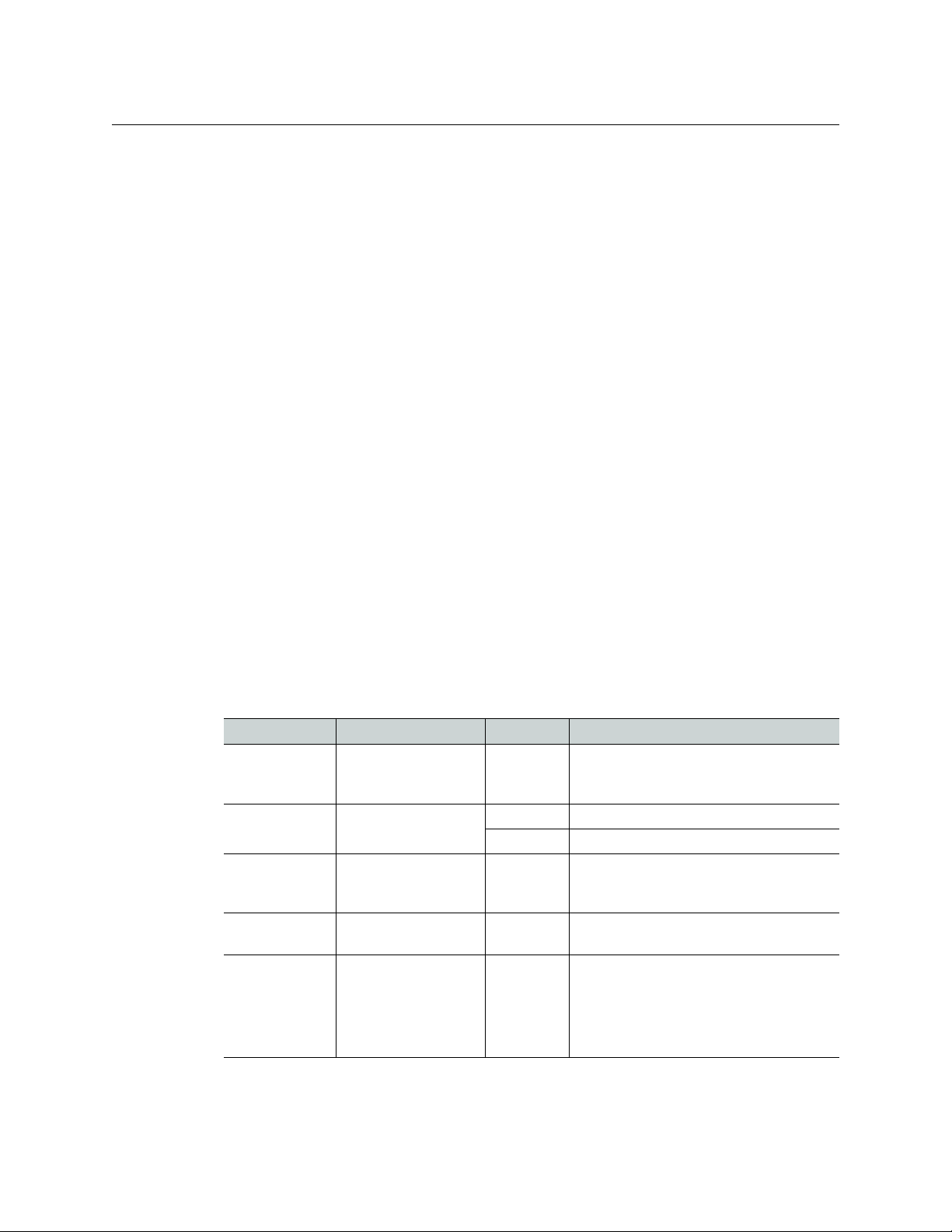
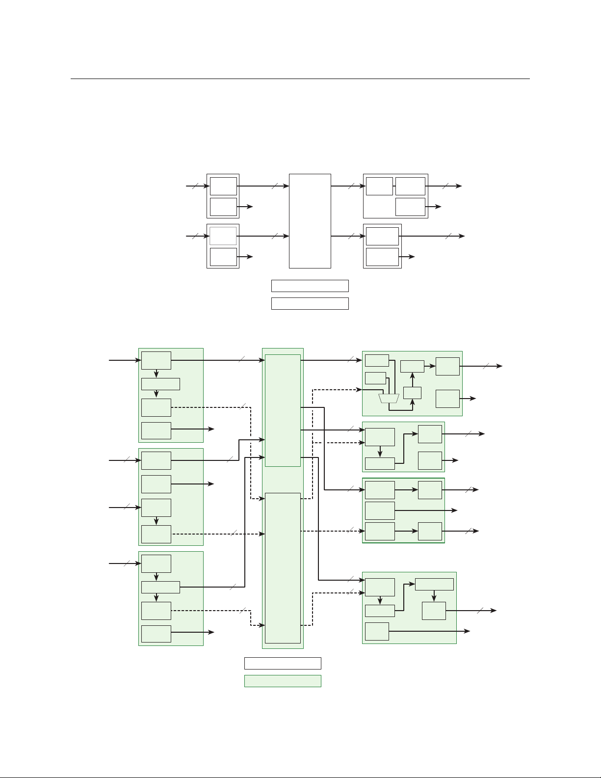
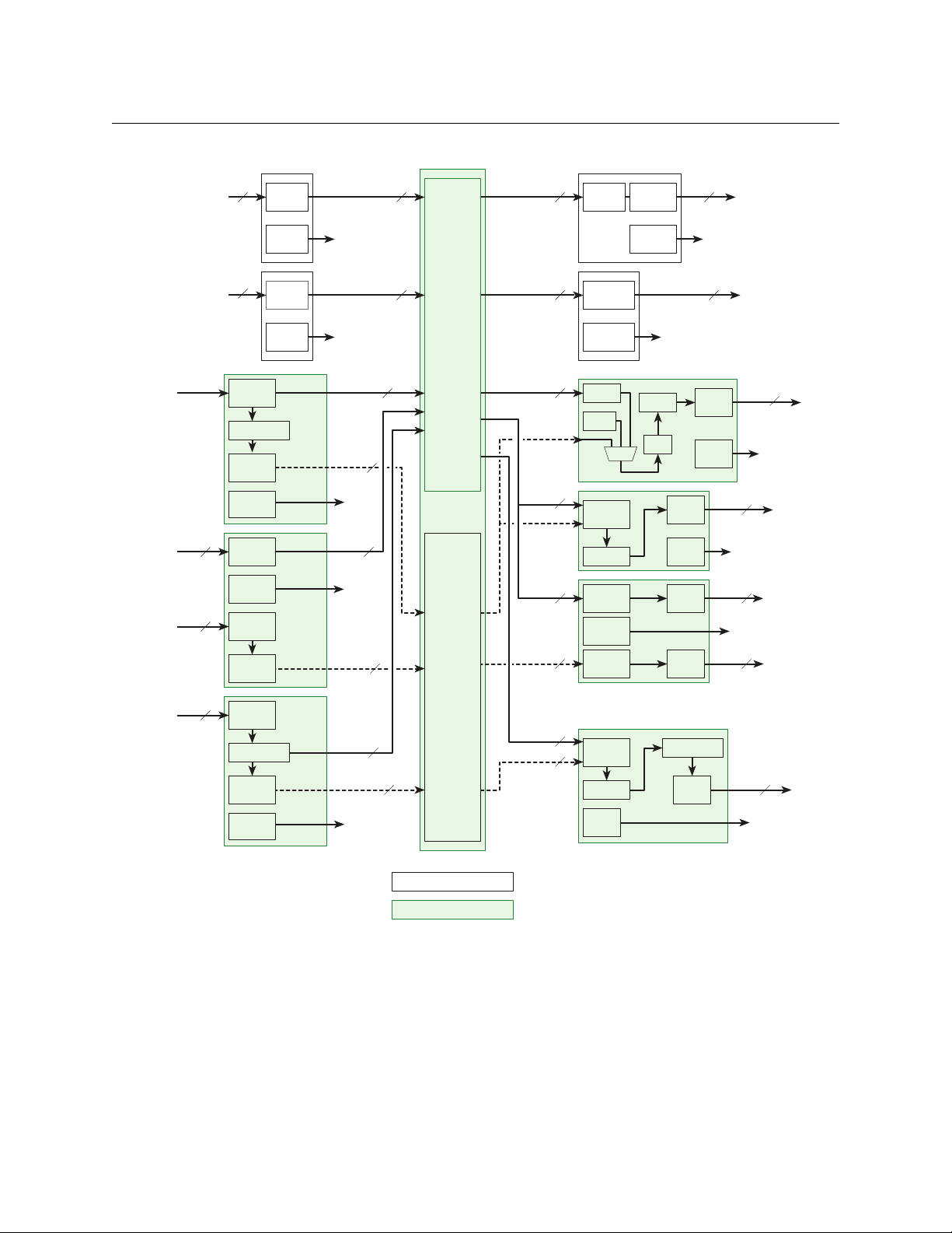
The following 3 illustrations show schematically how signals are routed in a frame with (1) only
standard I/O cards, (2) only hybrid I/O cards, and (3) both standard and hybrid I/O cards installed.
Fig. 1-1: Standard I/O Cards Only
4
Fig. 1-2: Hybrid Cards Only
Page 21
NV8500 Series
Reclocker
to Monitor
Card
18
Video
AES Async
(Non-Hybrid)
Standard
HD or 3Gig
Audio
Monitor
selector
Cable
Driver
AES
Transmitter
to Monitor
Card
18
18
18
Monitor
Selector
Input Cards
Output Cards
TDM
Matrix
(Audio)
Hybrid
XPT
Crosspoint
Matrix
(Video)
Monitor Cards (EM0663)
Control Cards (EM0833)
Monitor
Selector
Cable
Equalizer
to Monitor
Card
Audio
Standard
HD or 3Gig
AES Async
(Non-Hybrid)
to Monitor
Card
Video
AES
Receiver
Monitor
Selector
9
9
9
9
Hybrid
3Gig/TDM
(MADI)
Reclocker
to Monitor
Card
MADI
Format ter
Monitor
Selector
16 video
2 MADI
Cable
Driver
Cable
Driver
16 video
Hybrid
Embedder
3Gig
Monitor
Selector
Embedder
Cable
Driver
(with 256 audio
embedded)
to Monitor
Card
Reclocker
16 video
Hybrid
DEM/EMB
3Gig
Monitor
Selector
Emb.
Cable
Driver
(with 256 audio
embedded)
to Monitor
Card
Disemb.
Silence
Reclock
MUX
Hybrid
3Gig
Monitor
selector
Cable
Equalizer
Video only
Disembedder
(with 128 audio
embedded)
Audio
TDM MUX
Hybrid
3Gig/TDM
(MADI)
to Monitor
Card
to Monitor
Card
MADI
Receiver
16 video
16 video
128 audio
8 video
8 video
128 audio
64 audio
Monitor
Selector
Cable
Equalizer
Audio
TDM MUX
8 video
1 MADI
16 video
3 (SFP)
IP
Gateway
Monitor
Selector
Embedder
PHY
(SMPTE 2022-6)
Reclocker
IP
Gateway
Monitor
Selector
PHY
Video only
Decapsulator
(SMPTE 2022-6)
Audio
TDM MUX
to Monitor
Card
8 video
8 video
128 audio
Encapsulator
128 audio
3 (SFP)
to Monitor
Card
User’s Guide
Fig. 1-3: Both Standard and Hybrid I/O Modules
5
Page 22

Introduction
Overview of the Routers
Overview of the Routers
NV8500 series routers share common frame features. All I/O cards, crosspoint cards, monitor
cards, and control cards are installed through the frame front. All system connections and backplane modules are located at the rear of the frame.
The following is an overview of each router. For more information about any modules
mentioned, see the related topic:
• Inputs and Outputs on page 21
• Crosspoints on page 63
• Monitoring on page 89
• Router Control on page 83
• Power on page 119
Frame Cooling
The routers have one or more fan trays providing forced air cooling through five speedcontrolled fans. The fans draw air from the center and front of the router, through its door, and
exhaust it through the rear of the frame.
Each fan features speed control which spins the fan at the optimal rate required to ensure that a
constant temperature is maintained within the router frame. Temperature sensors at the inlet of
each fan increase or decrease the speed of the fan as required. Because the fans rotate only as
needed, fan noise is significantly reduced in partially loaded frames or in environments with
lower ambient temperatures. Maintaining a constant temperature ensures the proper operation
of router circuitry.
In the NV8144, NV8140, and the NV8280 frames, a single fan tray is located at the top of the
chassis. For the NV8576 (and NV8576-Plus) frames, there are two fan trays: one located at the top
and one located at the bottom of the frame. Each fan features two LEDs that indicate whether
the fan is receiving power and whether there is a failure. For more information, see Indicator
LEDs on page 193.
There is a removable air filter located on the inside of the door assembly. It is recommended that
filter maintenance be performed on a regular basis. For more information, see Air Flow
page 197.
on
Fuses
6
The NV8500 series routers have no user-serviceable fuses.
Page 23
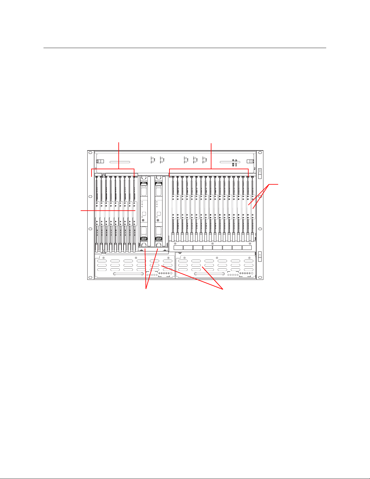
NV8144
NV8500 NV8500
PS8100
12345
POWER
GND
12345
48V
+
PS8100
12345
POWER
GND
12345
48V
+
Input Cards (16)Output Cards (8)
Control Cards (2)
Monitor
Card (1)
Crosspoint Cards (2) Power Supplies (2)
Fan
NV8500 Series
User’s Guide
Figure 1-4 shows the front of the NV8144 (with the door removed). At the top of the frame is the
fan tray. Directly below the fan tray are card slots. On the far left are 8 output card slots. Directly
to the right of the output cards is a single slot for the monitor card. Near the center of the frame,
to the right of the output cards, are 2 crosspoint card slots. The first slot holds the primary crosspoint card. The second slot holds a second, optional 144×144 crosspoint card for redundancy.
To the right of the crosspoint card slots are 16 input card slots. To the right of the input card slots
are 2 additional slots for the primary and secondary control cards. Below the card slots, at the
bottom of the frame, are 2 bays for PS8100 power supply modules.
Fig. 1-4: NV8144 (Front View with Door Removed)
7
Page 24
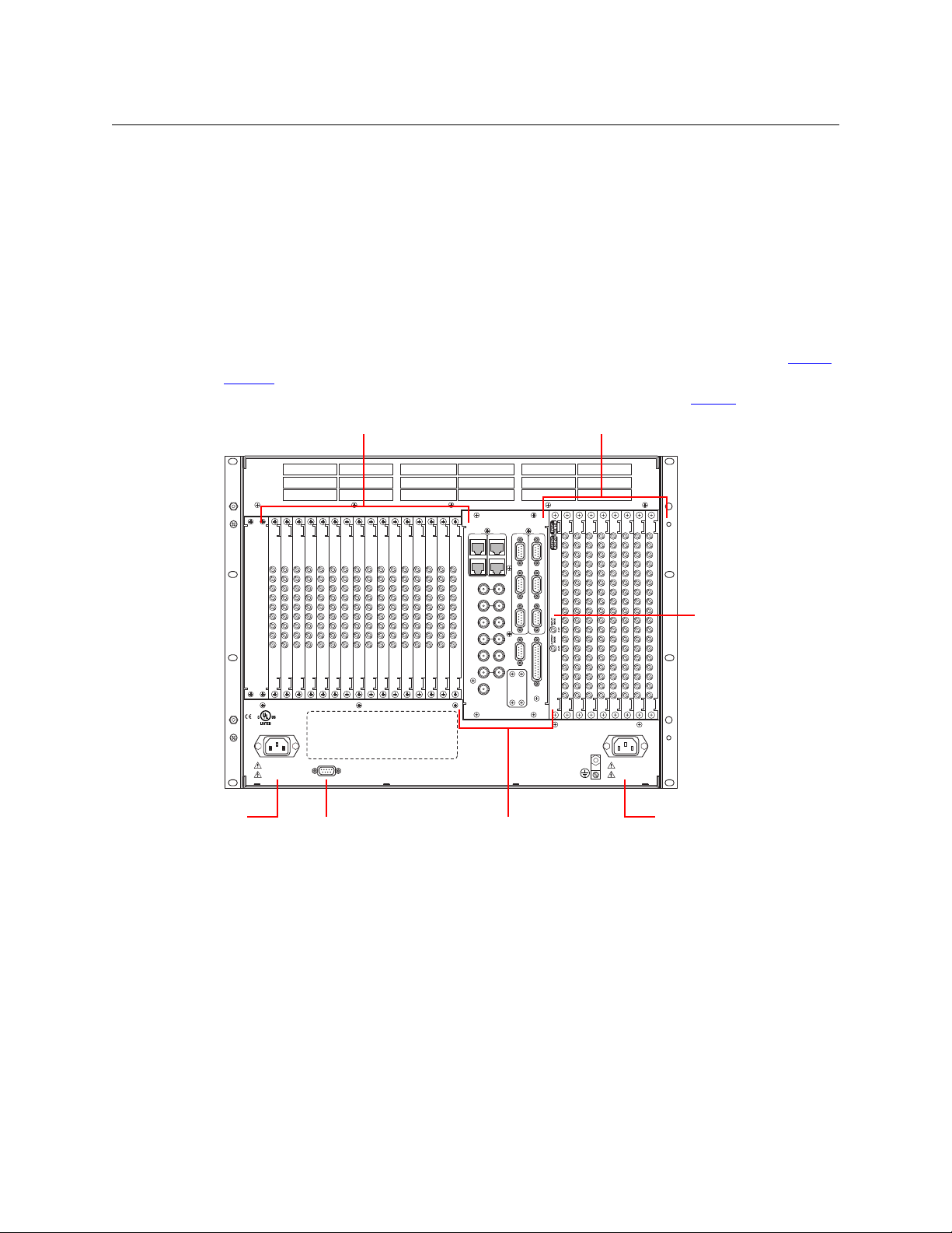
Introduction
DIAG (38.4 Kbaud)
CONTROL
POWER
SUPPLY
i
MONITORS
TIME CODE
NVISION AUX BUS
RTR EXP OUT
RTR EXP IN
AES REF 1
AES REF 2
VIDEO REF 2
VIDEO REF 1
RTR EXP
10/100 BT
RTR EXP
10/100 BT
CTRL 1
CTRL 2
ALARMS
CTRL 1
CTRL 2
DIAG (38.4 Kbaud)
PRI
SEC
SEC
PRI
90-130V~/180-250V~
12.5A/6.25A
50/60Hz
1125 WATTS MAX
PS1
PS2
90-130V~/180-250V~
12.5A/6.25A
50/60Hz
1125 WATTS MAX
E146905
CNTRL NO. 9K50
PROFESSIONAL
VIDEO/AUDIO
ALARMS
Output Backplanes (8)
Input Backplanes (16)
Monitor Backplane (1)
Power Connector
Power
Connector
PS Alarm
Connector
System
Connectors
Overview of the Routers
Figure 1-5 shows the rear of the NV8144. The farthest left-hand section is a blank plate that
corresponds in position to the control cards. Next to the control card plate are 16 input backplane slots. A mixture of different input cards and their backplane modules can be placed in
these slots.
The middle section contains system connections for audio reference, video reference, control
system connections, and power supply alarms.
To the right of the system connectors is one monitor backplane slot.
To the right of the monitor backplane are 8 output backplane slots. A mixture of different
output cards and their backplane modules can be placed in these slots.
At the very top of the frame is a grill for exhausting warm air dispersed by the fans. (See Frame
Cooling on page 6.) Near the bottom of the frame are two AC power connectors. To the right of
the left-hand power connection is a power supply alarm connector. (See Alarms
on page 109.)
8
Fig. 1-5: NV8144 (Rear View)
Page 25
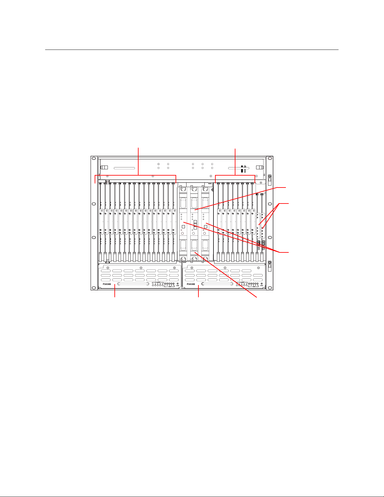
NV8140
NV8144
FAN 1
ALARM POWER
FAN 2
ALARM POWER
FAN 3
ALARM POWER
FAN 4
ALARM POWER
FAN 5
ALARM POWER
Input Cards (8)Output Cards (16)
Control Cards (2)
Redundant Crosspoint CardPower Supply
Fan
Crosspoint Cards (2)
Power Supply
Redundant Crosspoint Card
NV8500 Series
User’s Guide
Figure 1-6 shows the front of the NV8140 (with the door removed). At the top of the frame is the
fan tray. Directly below the fan tray are card slots. On the far left are 16 output card slots. Near
the center of the frame, to the right of the output cards, are 3 crosspoint card slots. The first and
third slots hold the regular crosspoint cards. The middle slot holds a optional redundant crosspoint card.
To the right of the crosspoint card slots are 8 input card slots. To the right of the input card slots
are 2 slots for the primary and secondary control cards. Below the card slots, at the bottom of
the frame, are 2 bays for PS8300 power supply modules.
Fig. 1-6: NV8140 (Front View with Door Removed)
The NV8140 does not have a monitor card slot and does not support signal monitoring.
The NV8140 requires PS8300 power supplies, not PS 8100s.
The crosspoint card slots for the NV8140 are narrower than the crosspoint slots for the NV8144.
Do not attempt to install the older (and now obsolete) EM0799 or EM0819 crosspoint cards in
the NV8140. Physical damage will result.
Frame sync input cards are not available for the NV8140.
9
Page 26
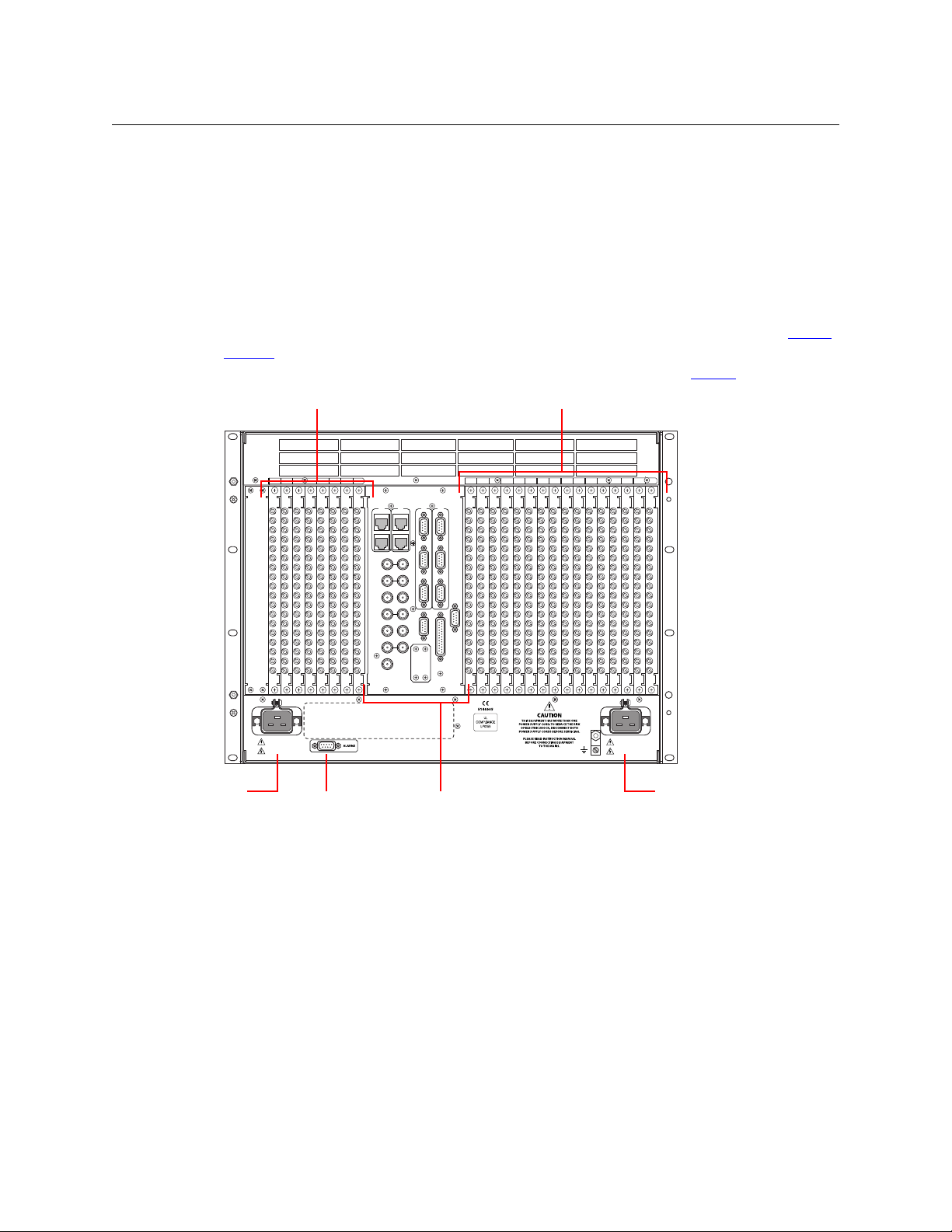
Introduction
12345678 234567810111213141516 91
POWER
SUPPLY
MONITORS
TIMECODE
NVISIONAUX BUS
RTR EXP OUT
RTR EXP IN
AES REF 1 AES REF 2
VIDEO REF 2
VIDEO REF 1
10/100BT 10/100BT
RTR EXP RTR EXP
CTRL 1
CTRL 2DIAG (38.4 Kbaud)
CTRL 1
CTRL 2DIAG (38.4 Kbaud)
ALARMS
CONTROL
PRI PRI
SEC
SEC
100 - 240V~
15A / 7.5A
50 / 60Hz
100 - 240V~
15A / 7.5A
50 / 60Hz
Output Backplanes (16)
Input Backplanes (8)
Power Connector
Power
Connector
PS Alarm
Connector
System
Connectors
Overview of the Routers
Figure 1-7 shows the rear of the NV8140. The farthest left-hand section is a blank plate that
corresponds in position to the control cards. Next to the control card plate are 8 input backplane
slots. A mixture of different input cards and their backplane modules can be placed in these
slots.
The middle section contains system connections for audio reference, video reference, control
system connections, and power supply alarms.
To the right of the monitor backplane are 16 output backplane slots. A mixture of different
output cards and their backplane modules can be placed in these slots.
At the very top of the frame is a grill for exhausting warm air dispersed by the fans. (See Frame
Cooling on page 6.) Near the bottom of the frame are two AC power connectors. To the right of
the left-hand power connection is a power supply alarm connector. (See Alarms
on page 109.)
10
Fig. 1-7: NV8140 (Rear View)
The NV8140 uses PS8300 power supplies, not PS8100s. It has two C19 power connectors and
require 20A plant lines. The cable supplied in North America has a NEMA L5-20P connector at
the other end. For customers outside North America, we ship these power cords with the NEMA
end cut off.
The input backplane modules of the NV8140 have 18 connectors, not 9 as for the other routers.
Page 27
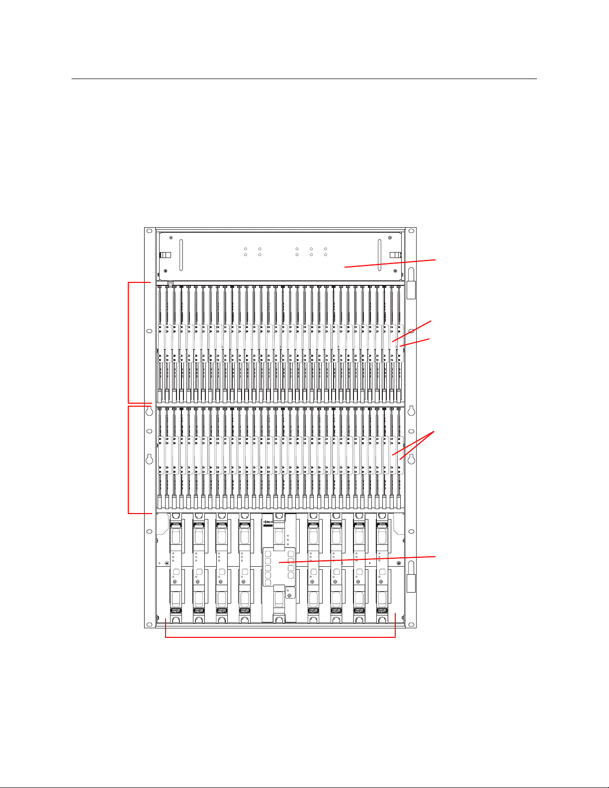
NV8280
NV8280
144 X 144
3Gig
Redundant
XPT
STANDBY
PATH
LITE
ALARM
ACTIVE
POWER
REDUNDANT OPERATION
1
7
2
8
3
9
4
10
NV8500 NV8500NV8500 NV8500 NV8500 NV8500 NV8500 NV8500 NV8500
Output
Cards (32)
Input
Cards (32)
Control Cards (2)
Crosspoint Cards (8)
Fan Tray
Output Monitor Card
Redundant
Crosspoint
Input Monitor Card
NV8500 Series
User’s Guide
Figure 1-8 shows the front of the NV8280 (with the door removed). At the top of the frame is the
fan tray. Directly below are 32 output cards slots. Below the output cards are 32 input card slots.
To the far right of the output card slots are two additional slots for monitor cards. Similarly, to
the far right of the input card slots are two additional slots for the primary control card and
secondary control card.
Below the input card slots, at the bottom of the frame, are 10 crosspoint card slots. The middle 2
crosspoint card slots are for an optional redundant crosspoint. The other 8 slots are for crosspoint cards.
Fig. 1-8: NV8280 (Front View with Door Removed)
11
Page 28
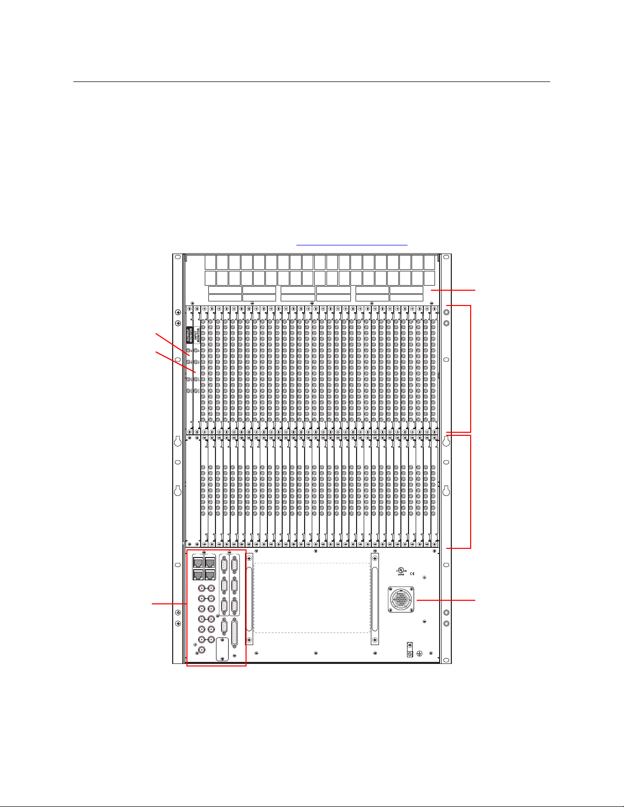
Introduction
10/100 BT
RTR EXP
10/100 BT
RTR EXP
VIDEO REF 1
PRI
SEC
CONTROL
CTRL 1
CTRL 2
CTRL 1
CTRL 2
DIAG (38.4 Kbaud)
DIAG (38.4 Kbaud)
VIDEO REF 2
AES REF 1
AES REF 2
RTR EXP IN
ALARMS
RTR EXP OUT
NVISION AUX BUS
POWER
SUPPLY
MONITORS
TIME CODE
E146905
POWER INPUT
PRI
SEC
Output Backplanes (32)
Input Backplanes (32)
Output Monitor
Backplane
System
Connectors
Power Connector
Fan
Input Monitor
Backplane
Overview of the Routers
Figure 1-9 shows the rear of the NV8280. At the very top of the frame is a grill for exhausting
warm air dispersed by the fans. Directly below the fan tray, starting from the left, are 2 monitor
backplane slots. To the right of the monitor backplane slots are 32 output backplane slots. A
mixture of different output cards and their backplane modules can be placed in these slots.
Directly below the output slots, starting from the left, is a blank back plate that corresponds in
position to the control cards. Next to the blank back plate are 32 input backplane slots. A
mixture of different input cards and their backplane modules can be placed in these slots.
At the very bottom of the frame, on the left-hand side, are system connections for audio reference and video reference, control system connectors, and alarm connectors. On the right-hand
side is a single power connector that connects the router to an NV8300 power supply frame. For
information about the NV8300, see Power Supply Distribution
on page 121.
Fig. 1-9: NV8280 (Rear View)
12
Page 29

NV8576
NV8500 Series
User’s Guide
Figure 1-10, next page, shows the front of the NV8576.
The router is divided into three regions: upper, middle, and lower. The upper and lower regions
each have 32 slots for output cards and 32 slots for input cards. The NV8576 thus has a total of
64 output card slots and 64 inputs card slots. Cards in the lower region of the frame are installed
upside down (i.e., rotated 180° with respect to those in the upper region).
In the upper region, to the far right of the output card slots, are two monitor card slots. Similarly,
to the far right of the input card slots are two slots for the primary control card and the
secondary control card. The lower region has two more monitor card slots, at the far left of the
output cards. (The lower region does not have control cards.)
In the middle region are 10 slots for crosspoint cards. The middle 2 crosspoint card slots hold an
optional redundant crosspoint. The remaining 8 slots are for crosspoint cards.
13
Page 30
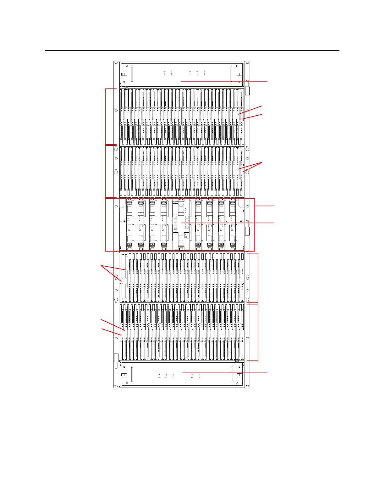
Introduction
NV8280
144 X 144
3Gig
Redundant
XPT
STANDBY
PATH
LITE
ALARM
ACTIV
POWE
REDUNDANT OPERATION
1
7
2
8
3
9
4
10
NV8500 NV8500NV8500 NV8500 NV8500 NV8500 NV8500 NV8500 NV8500
Output
Cards (32)
Input
Cards (32)
Control Cards (2)
Crosspoint Cards (8)
Fan Tray
Input Monitor Card
Redundant
Crosspoint
Fan Tray
Output
Cards (32)
Input
Cards (32)
Input Monitor Card
Unused
slots (2)
Output Monitor Card
Output Monitor Card
Overview of the Routers
Fig. 1-10: NV8576 (Front View with Door Removed)
14
Figure 1-11, following, shows the rear of the NV8576. The upper and lower regions each have a
32 output slots and 32 input slots, for a total of 64 output slots and 64 input slots.
In the upper region, to the far left of the output backplanes are two additional backplanes for
monitoring signals. Likewise, in the lower region, to the far right of the input backplanes are two
more backplanes for monitoring signals.
Page 31

NV8500 Series
10/100 BT
RTR EXP
10/100 BT
RTR EXP
VIDEO REF 1
PRI
SEC
CONTROL
CTRL 1
CTRL 2
CTRL 1
CTRL 2
DIAG (38.4 Kbaud)
DIAG (38.4 Kbaud)
VIDEO REF 2
AES REF 1
AES REF 2
RTR EXP IN
ALARMS
RTR EXP OUT
NVISION AUX BUS
POWER
SUPPLY
MONITORS
TIME CODE
E146905
POWER INPUT
PRI
SEC
CONTROL
POWER INPUT
Output Backplanes (32)
Input Backplanes (32)
Output Monitor Backplane
System
Connectors
Power Connector 1
Fan
Power Connector 2
Output
Backplanes
(32)
Input
Backplanes
(32)
Input Monitor Backplane
Output Monitor Backplane
Input Monitor Backplane
User’s Guide
In the center of the frame, on the left-hand side, are system connections for audio and video
references, control systems, and alarms. On the right-hand side are two power connections for
connecting the router to two NV8300 power supply frames.
Fig. 1-11: NV8576 (Rear View)
15
Page 32

Introduction
Preparing for Installation
Expanded NV8576-Plus
The expanded NV8576-Plus router comprises two 32RU frames that have the same structure as
the NV8576 frames. Please refer to figures 1-10 and 1-11, preceding, to see NV8576-Plus frame
structure.
Note that the expanded NV8576-Plus, consisting of 2 frames, will require 4 NV8300 power
supply frames, two for each frame.
The NV8576-Plus, of course, will be populated with expansion output cards and backplanes
instead of regular output cards and backplanes. Expansion output cards in one frame connect
to matching expansion output cards in the other frame. An expansion output card in the first
frame must match the expansion output card to which it is connected in the second frame in
type and position. See Expansion I/O Cards
NV8576-Plus (Stand-Alone)
A stand-alone NV8576-Plus is a single 32RU frame that have the same structure as the NV8576
frame. Please refer to figures 1-10 and 1-11, preceding to see the stand-alone NV8576-Plus
frame structure.
The stand-alone NV8576-Plus requires 2 NV8300 power supply frames.
The stand-alone NV8576-Plus, of course, will be populated with expansion output cards.
Because there is only one frame, expansion cables are not used.
on page 102 for details about matching card types.
Preparing for Installation
Before you set up the router, be sure to review the information in this section.
When your products arrive, immediately inspect the shipping container. If the container is
damaged, unpack and inspect the contents. If the contents are damaged, notify the carrier
immediately.
When unpacking the shipping container, look for the packing slip and compare it against the
contents to verify that everything ordered was received. If anything is missing (or if equipment is
damaged unrelated to shipping), please contact Miranda.
Your shipment does not contain mounting racks, network cables, video cables, mounting
screws, or grounding wire. If you have ordered an NV8280, NV8576, or NV8576-Plus, included in
the shipment will be one or more NV8300 external power supply frames.
Shipments of the NV8576 and NV8576-Plus also include a rack-mounting kit, including a jack,
lifting handles, and instructions.
You will need the following items for installation:
A computer running Windows
required for installing the Miranda Router Configurator and other configuration software.
Computer hardware requirements:
CD drive.
RS-232 serial COM port (DE9) capable of operating at 38.4Baud.
2000, Windows® XP Professional, or Windows® 7. This is
®
16
10BaseT or 10/100BaseT (preferred) Ethernet port.
Page 33

100 Mb/s Ethernet switch with at least 4 ports.
Ethernet cables (category 5) with RJ-45 connectors.
RS-232 serial cable with DE9 connectors, wired straight-through, male to female.
NV8500 Series
User’s Guide
Coaxial cable and 75
Belden 1855a, or equivalent, cable and DIN 1.0/2.3 connectors and/or LC connectors and
fiber optic cable.
Reference video source (BNC) at the line rate appropriate for your system.
(Optional) tool for connecting DIN 1.0/2.3 connectors.
Frame rack suitable for mounting the router.
Installation Steps
Installation and (re)configuration tasks should be performed in a specific order to avoid possible
complications.
1 Mount the router.
Before rack-mounting, remove all installed modules to make the router easier to lift into
place. (NV8500 series routers ship with the cards and backplanes installed.)
Before making any connections or installing any modules, the router and other frames
should be mounted in a rack so that the frame remains stable when you are connecting
cables to the frame. See Rack Mount
2 (Re)Install cards and backplanes.
These include I/O cards, monitor cards, I/O backplanes, monitor backplanes, crosspoint
cards, and control cards.
NV8500 series routers ship with the cards and backplanes installed. You might have to
remove the cards and backplanes initially to be able to lift the router into place in its rack.
For information about the modules and installation instructions, see the related section:
• Inputs and Outputs on page 21
• Crosspoints on page 63
• Monitoring on page 89
3 Make control connections.
Router control system connections allow the router and router control system to communicate. See Router Control
4 Make expansion connections.
If you installing an NV8576-Plus, make the necessary expansion connections between the
two frames. See Expanded NV8576-Plus
5 Make (optional) alarm connections.
Alarm connections communicate system and power status to external indicators. Use the
system alarm connector on the router frame.
If you are installing an NV8280, NV8576, or NV8576-Plus, you can use the power supply
alarm connectors on the NV8300 power supply frame. (The NV8144 and NV8140 do not use
W BNC connectors.
on page 18.
on page 83.
on page 97.
17
Page 34

Introduction
Rack Mount
Rack Mount
an external power supply and have their own power supply alarm connectors.) See Alarms
on page 109.
6 Connect to power.
After all other modules are installed and connections are made, connect the router to AC
power. The NV8144 and NV8140 connect directly to AC power. The NV8280, NV8576, and
NV8576-Plus frames connect to the external NV8300 power supply frame which connects to
AC power.
Note: be sure to insert PS8300 power supply modules in the NV8300 after all power connec-
tions are made. This is how you turn the router on and off. The PS8300s are hot-swappable.
See Pow
Note: each PS8300 requires a 20A circuit at 110
7 Launch the Miranda Router Configurator.
The Miranda Router Configurator (MRC) is used to configure the router and monitor system
status. MRC should be installed on a PC in the same network as the router control system.
See the Miranda Router Configurator User’s Guide.
er on page 119.
VAC. A 22 0 VAC line requires 10 A circuitry.
NV8500 series router frames are designed to fit in a 19” (482.6 mm) EIA rack. The NV8280, the
NV8576, and the NV8576-Plus use one or more NV8300 external power supply frames that also
requires rack-mounting. It is not required that both the router and power supply frames be
mounted in the same rack.
For details about power requirements and how to connect to power, see Pow
Before mounting frames in the rack, determine the placement of the router frame, and if applicable, the NV8300 power supply in the rack and the rack in the facility. When placing the frames
and rack keep in mind the following requirements:
er on page 119.
• Vertical space for the router frame:
NV8144 frames occupy 8 RUs.
NV8140 frames occupy 8 RUs.
NV8280 frames occupy 16 RUs.
NV8576 frames occupy 32 RUs.
Stand-alone NV8576-Plus frames occupy 32 RUs.
Each of the two frames of an expanded NV8576-Plus occupies 32 RUs.
• Vertical space for the NV8300 power supply frame:
The NV8144 and the NV8140 do not use external power supply frames.
For an NV8280, only one power supply frame is required, totalling 3 RUs.
For an NV8576 or a stand-alone NV8576-Plus, two power supply frames are required totalling 6 RUs.
For an expanded NV8576-Plus, four power supply frames are required totalling 12 RUs.
• Vertical space for NV8900 MADI Interfaces, each of which requires 1 RU. See NV8900 MADI
Interfaces on page 54. (NV8900s are optional.)
Note: Grass Valley’s NV8900 interfaces can concentrate AES signals in a MADI stream for connection to a MADI input or extract AES signals from a MADI output. For details, see NV8900
18
Page 35

MADI Interfaces on page 54. Future MADI interfaces to analog audio are planned.
• AC power connects directly to the NV8144 frame and to the NV8140 frame. AC power con-
nects to the NV8300 power supply frame used for the other NV8500 routers. The NV8144
requires a 15A circuit for each connection. The NV8140 requires a 20A circuit for each connection. The NV8300 requires a 20A circuit for each of its power supply modules in 110 VAC
environments. (There are 4 modules in each NV8300 power supply frame.)
In 220 VAC environments, a 10A circuit is required for NV8300 power supplies.
• If you are installing an expanded NV8576-Plus (two frames), the frames must be located near
each other, side-by-side or back to back, so that you can make expansion connections
between the frames. The distance between the frames is limited by the length of expansion
cables (4 meters). See Connecting the NV8576-Plus Frames
• To ensure proper cooling, leave space for unrestricted air flow through the front of the
router, and a minimum of 6-inches of clearance at the rear where the cooling fans exhaust
warm air.
• Allow space for cabling to the router’s I/O connectors.
To Rack Mount the Router
NV8500 Series
User’s Guide
on page 104.
1 Temporarily place the router frame near the rack in which it is to be installed.
2 Remove the front door by turning its retaining screws counter clockwise, opening the door,
and lifting it free of its hinges.
Important: never use the front door handle to lift the frame.
3 The router was shipped with control cards, crosspoint cards, I/O cards, I/O backplanes, and
fan trays installed. Remove them to make the frame lighter for installation. If you do remove
the cards, be sure to note which card was installed in which slot for later reinstallation.
CAUTION
Handle all circuit boards with care. Be sure to use electrostatic discharge (ESD) protection and place the circuit boards in ESD bags or on an ESD surface. Do not stack boards
without ESD protection.
4 Lift the frame into position and attach the router frame to the front of the rack with the
appropriate screws. Be sure to place screws in all frame mounting screw holes.
CAUTION
An equipment jack or two persons are required to lift and install the router frame. The
router frame is considered too heavy for one person to lift and install in the rack.
Note: NV8576 frames are shipped with a rack-mounting kit, including a jack, a shelf for supporting the frame while it is still not secured with screws, handles for lifting the frame into
place, and instructions for rack-mounting using the kit. An NV8576-Plus is also shipped with
the rack-mounting kit. An NV8280 frame is shipped with a handle for lifting it into place.
5 Reinstall the fan trays in the fan tray bays. The fan tray openings face the interior of the
router. In the NV8576 and NV8576-Plus frames, the openings of the upper fan tray face down
and the openings in the lower fan tray face up.
19
Page 36

Introduction
Rack Mount
6 Reinstall control cards, crosspoint cards, I/O cards, I/O backplanes, monitor cards, and moni-
tor backplanes. Be sure to install them in the correct location. The router was configured at
the factory with the cards in a specific location. If you install I/O cards in a different location,
the router will have to be reconfigured before it can run properly.
7 If you are using NV8300 power supplies, perform the following steps:
a If the NV8300 was shipped with the PS8300 power supply modules in the frame, remove
the modules.
CAUTION
Do not re-insert the PS8300 power supply modules until after you have made all
power connections. For more information, see
page 126.
b Lift the power supply frame into position and attach the power supply frame to the front
of the rack with the appropriate screws. Place screws in all frame mounting screw holes.
c Repeat steps a and b for additional power supply frames.
8 Re-mount the front door.
9 Wait until you have completed all installation tasks before you reinstall PS8300 power supply
modules, powering up the router. (See Connecting to Power
Connecting to Power on
on page 126.)
20
Page 37

I/O modules include input cards, output cards, and their backplanes. Input cards receive
incoming signals through connectors on their backplanes and forward them to crosspoint
cards. The crosspoint cards route the signals, as directed by the control card, to output cards.
The signals are then distributed from the output card through connectors on their backplanes.
For a comprehensive list of I/O modules and corresponding backplanes with part numbers, see
Part Numbers
on page 213.
Topics
Types of Input and Output . . . . . . . . . . . . . . . . . . . . . . . . . . . . . . . . . . . . . . . . . . . . . . . . . . . . . . . . . . . . . . . . 21
Slot Numbering
I/O Backplanes
I
/O Cards . . . . . . . . . . . . . . . . . . . . . . . . . . . . . . . . . . . . . . . . . . . . . . . . . . . . . . . . . . . . . . . . . . . . . . . . . . . . . . . . . 46
. . . . . . . . . . . . . . . . . . . . . . . . . . . . . . . . . . . . . . . . . . . . . . . . . . . . . . . . . . . . . . . . . . . . . . . . . . 36
. . . . . . . . . . . . . . . . . . . . . . . . . . . . . . . . . . . . . . . . . . . . . . . . . . . . . . . . . . . . . . . . . . . . . . . . . . . 39
Making I/O Signal Connections
Audio and Video References
Time Code
. . . . . . . . . . . . . . . . . . . . . . . . . . . . . . . . . . . . . . . . . . . . . . . . . . . . . . . . . . . . . . . . . . . . . . . . . . . . . . . . 62
Types of Input and Output
Inputs and Outputs
. . . . . . . . . . . . . . . . . . . . . . . . . . . . . . . . . . . . . . . . . . . . . . . . . . . . . . . . . . . 59
. . . . . . . . . . . . . . . . . . . . . . . . . . . . . . . . . . . . . . . . . . . . . . . . . . . . . . . . . . . . . . 60
Although this chapter discusses each card type and its signal numbering in detail, here it
presents a tabular view of the cards:
Input Card Type Signals Remarks
Standard HD input 9 video.
18, video (NV8140)
Standard 3Gig input 9 video;
18 video (NV8140)
AES async input
Disembedder 8 video;
Frame sync
(disembedder)
IP gateway
(disembedder)
3Gig/TDM input 8 video + 1 MADI;
a. The NV8140 does not support AES async.
a
9 audio Accepts AES pairs; coax or shielded twisted pair
16 video (NV8140)
8 video Accepts 3Gig, HD, or SD, coax only; 16 embedded
8 video Receives packetized video (via 10GE SFPs).
16 video + 2 MADI (NV8140)
Accepts HD or SD; coax
Accepts 3Gig, HD, or SD; coax or fiber
(STP)
Accepts 3Gig, HD, or SD, coax only; 16 embedded
audio channels for each video port
audio channels for each video port; RJ-45 port for
configuring frame sync functions.
Accepts 3Gig, HD, or SD; 16 embedded audio
channels for each video stream; RJ-45 port for
configuring IP functions.
Accepts 3Gig, HD, or SD and MADI stream(s) up
to 64 channels; coax only
21
Page 38

Inputs and Outputs
Types of Input and Output
Output Card Type Signals Remarks
Standard HD output 18 video Transmits HD or SD; coax
Standard 3Gig output 18 video Transmits 3Gig, HD, or SD; coax or fiber
AES async output
M3 18 video Transmits 3Gig, HD, or SD; M3 and coax
Embedder 16 video Transmits 3Gig, HD, or SD, coax only; 16 embedded audio
Disembedder/Embedder
a
18 audio Transmits AES pairs; coax or shielded twisted pair (STP)
channels for each video port
16 video Transmits 3Gig, HD, or SD, coax only; 16 embedded audio
channels for each video port; special functions
IP gateway
(embedder)
3Gig/TDM output 16 video + 2 MADI Transmits 3Gig, HD, or SD and 2 MADI streams, 56 or 64
a. The NV8140 does not support AES async.
Expansion Output Card
Type
Standard HD output 9 video Transmits HD or SD; coax
Standard 3Gig output 9 video Transmits 3Gig, HD, or SD; coax or fiber
AES async output 9 audio Transmits AES pairs; coax or shielded twisted pair (STP)
Embedder 8 video Transmits 3Gig, HD, or SD, coax only; 16 embedded audio
Disembedder/Embedder
3Gig/TDM output 8 video + 1 MADI Transmits 3Gig, HD, or SD and 1 MADI streams, 56 or 64
8 video Transmits packetized video (via 10GE SFPs). Accepts 3Gig,
HD, or SD; 16 embedded audio channels for each video
stream; RJ-45 port for configuring IP functions.
channels each; coax only
Signals Remarks
channels for each video port
8 video Transmits 3Gig, HD, or SD, coax only; 16 embedded audio
channels for each video port; special functions
channels; coax only
Expansion cards are applicable only to the NV8576-Plus expanded router. (The NV8576-Plus
expanded routers do not accept IP gateway output cards. No expansion IP gateway output
cards exist yet.)
The expansion output cards all have two inter-frame connections, in addition to their output
connectors.
The “special functions” of the disembedder/embedder cards are (1) null audio and (2) passthrough audio. See N
ull Audio and Pass-Through Audio, on page 75.
There is no M3 expansion output card and there is no M3 input card.
22
Backplanes
Backplane modules have signal connectors of 3 types, in general:
• Coax (DIN 1.0/2.3)
• Fiber optic (IP gateway cards, having SFP connector modules housing LC connectors)
See Backplanes Having SFP Modules
• WECO quick-release connectors (5-pin or 3-pin, for twisted pair wiring).
on page 42.
Page 39

NV8500 Series
User’s Guide
• M3 connectors. See M3 Cards on page 185.
Expansion backplanes, used for the NV8576-Plus only, have additional expansion connectors.
For routers other than the NV8140, input backplanes have 9 connectors. For the NV8140, input
backplanes have 18 connectors.
For routers other than the NV8140, frame sync input backplanes have 9 connectors and an additional RJ-45 (Ethernet) connector for configuring frame sync functions. Frame sync cards and
backplanes are not available for the NV8140.
All output backplanes have 18 connectors. All expansion output backplanes have 9 output
connectors and two inter-frame connectors.
Backplanes with Fiber Optic Connectors
The SFP connectors of these backplane modules have two ports each:
89
nc
1234567
Fiber Input
123456789101112131415161718
Fiber Input (NV8140)
123456789101112131415161718
Fiber Output
89
nc
1234567
Fiber Expansion Output
Except for the NV8140, the fiber input backplanes have 9 ports. The 10th port is not connected.
The output backplanes have 18 ports and the input card for the NV8140 has 18 ports.
The expansion output card has 9 ports and two 28-pin expansion connectors. (The 10th SFP
port is not connected.)
When these backplanes are used with hybrid I/O cards, one or two of the ports remain unused.
23
Page 40

Inputs and Outputs
Coax Output
Coax Input
Coax Expansion Output
123456789101112131415161718
123456789101112131415161718
123456789
123456789
123456789
Coax Input (NV8140)
Coax Input (Frame Sync)
18
1
10
9
M3
OUT
M3 Output
COAX
IN
Types of Input and Output
Backplanes with Coax Connectors
These backplane modules have coax (Din 1.0/2.3) connectors:
The coax backplanes are used for standard I/O, disembedder cards, embedder cards, MADI cards
(a.k.a, TDM cards), and AES async cards.
Generally, the coax input backplanes have 9 ports. The output backplanes have 18 ports. The
expansion output card has 9 ports and two 28-pin expansion connectors.
The frame sync input backplane has an additional Ethernet port for the configuration of the
frame sync card.
When these backplanes are used with hybrid I/O cards, one or two of the ports remain unused.
The M3 output backplane module is unique. It has a single 16-port “M3” connector supporting
16 of the outputs of the M3 card. The two remaining ports are presented on two coax connectors. See M3 C
ards on page 185.
Backplanes with WECO Connectors
These backplane modules have 3- and 5-pin WECO quick-release connectors:
3456789
1
3
5
7
9
6
8
2
4
12
AES Async Input
2
13456789101112131415161718
AES Async Output
AES Async Expansion Output
Backplanes with WECO connectors are used for balanced AES async inputs and outputs. These
backplanes are for asynchronous AES cards only.
The input backplanes have 9 ports. The output backplanes have 18 ports. The expansion output
card has 9 ports and two 28-pin expansion connectors.
24
Page 41

NV8500 Series
User’s Guide
Backplanes for IP Gateway Cards
These backplane 3 SFP connectors:
IP Gateway Input
IP Gateway Output
The IP gateway backplanes have an additional Ethernet port for configuration.
Each of the 3 SFP connectors has two ports.
The 3 SFP connectors of the input card, combined, support 8 packetized video streams and the
3 SFP connectors of the output card, combined, support 8 packetized video streams.
See IP Gateway C
ards on page 163.
Backplanes for Hybrid Cards
For hybrid cards, the backplane connectors are used differently.
Card Type Video MADI 10GE Unused Remarks
Disembedder 8
16
Frame sync
(disembedder)
Embedder 16 — 2 16 embedded audio channels for each video
IP gateway,
input
IP gateway,
output
MADI input 8
MADI output 16 2 — 56 or 64 MADI channels on each of the 2 audio
a. For the NV8140 only.
b. Not available for the NV8140.
c. There are no IP gateway expansion output cards.
8 — 1 16 embedded audio channels for each video plus
——3
——3
16
—
a
—
b
c
1
a
2
1
2
— Eight packetized video streams received on the 3
— Eight packetized video streams output on the 3
—
—
16 embedded audio channels for each video
an RJ-45 port for configuring frame sync functions.
SFP connectors.
SFP connectors.
Up to 64 MADI channels on 1 audio port
ports
25
Page 42

Inputs and Outputs
Disembedder
Disembedder,*
Embedder
Embedder
Expansion Output
3Gig/TDM
Input
3Gig/TDM
Input,* Output
3Gig/TDM
Expansion Output
1
2
3
4
5
6
7
8
9
1
2
3
4
5
6
7
8
9
10
11
12
13
14
15
16
17
18
1
2
3
4
5
6
7
8
9
1
2
3
4
5
6
7
8
9
1
2
3
4
5
6
7
8
9
10
11
12
13
14
15
16
17
18
1
2
3
4
5
6
7
8
9
Video
(with
Emb.
Audio)
Video
(with
Emb.
Audio)
Video
(with
Emb.
Audio)
Video
(with
Emb.
Audio)
unused
unused
unused
unused
Video
Video Video
Video
MADI
MADI
MADI
MADI
Types of Input and Output
Figure 2-1 shows the hybrid port assignments of the coax I/O backplanes:
26
Fig. 2-1: I/O Backplane Modules As Used for Hybrid I/O
The fiber and WECO backplanes have the same port numbering method as the coax backplanes.
Note that the coax backplanes used for hybrid cards are also used for standard cards. If, for
example, you exchange a standard card for a hybrid card in a particular slot, it is not necessary to
change the backplane, as long as the card is a coax-compatible card.
The video ports of frame sync input backplane modules follow the same pattern as for the
disembedder backplane modules.
The NV8140 is the only router in the NV8500 family that uses 18-connector disembedder (input)
backplanes and 18-connector MADI (3Gig/TDM) input backplanes. (Frame sync input backplanes are not available for the NV8140.)
See Backplanes Having SFP Modules
on page 42 for IP gateway signal numbering and ordering.
See M3 Cards on page 185 for M3 signal numbering and ordering.
Page 43

NV8500 Series
1
2
3
4
5
6
7
8
9
10
11
12
13
14
15
16
17
18
19
20
21
22
23
24
25
26
27
28
29
30
31
32
33
34
35
36
Coax inputs shown. Fiber optic and
WECO connectors are similar.
Outputs are similar, but each output
card has 18 connectors.
Expansion outputs (used by the
NV8576-Plus only) are similar and have
9 output connectors.
IP gateway cards do not have video
connectors. This ordering does apply
to IP gateway cards.
User’s Guide
Signal Numbering
When you are facing the rear of the router frame, where signal connections are made, signal
numbers are assigned, in increasing order, from top-to-bottom and from right-to-left.
This is true even in the NV8576 and NV8576-Plus where I/O cards and their backplanes in the
lower bays are rotated 180° from those in the upper bays.
See Figure 2-2, following.
Fig. 2-2: Connector Ordering
Also, for the NV8576 and NV8576-Plus, slot numbers increase right-to-left, in sections. The
sections are disjoint (non-contiguous). See Slot Order for Port Numbering
on page 37.
For standard routers, each input and output connector has a unique signal number assigned to
it. For standard video cards, and AES async cards, port numbering is straightforward: each
connector supports one video signal or one AES pair, as the case may be.
For hybrid routers, there are two numbering sequences, one for video signals and one for audio
signals. Keep this in mind when working with hybrid I/O cards that support both video and
audio. For hybrid video and audio, a single connector represents multiple inputs (or outputs).
Signal numbering is more complex.
27
Page 44

Inputs and Outputs
Types of Input and Output
I/O Space
Whether a router has standard cards or hybrid cards, each router has an I/O port “space” as listed
in this table:
Router Inputs
NV8144 144 144 2304 2304
NV8140
NV8280 288 576 4608 9216
NV8576 576 1152 9216 18432
a
Outputs
c
144 288 2304 4608
a
Audio Inputs
b
Audio Outputs
NV8576-Plus
(stand-alone)
NV8576-Plus
(expanded)
a. Either video or AES async.
b. For hybrid routers.
c. The NV8140 does not support AES async.
d. The expanded NV8576-Plus has two frames.
576 576 9216 9216
1152 1152 18432 18432
d
However, hybrid routers do not have circuitry for all the port numbers in their port space.
Each video port and each AES async port is an element of the router’s crosspoint matrix.
Hybrid audio ports are elements of a hybrid router’s TDM audio switching “matrix.”
Each I/O card also has an I/O port space within the port space of the router:
Card Video Ports
Input 9 144
NV8140 input 18 288
Output 18 288
Expansion output 9 144
a. Either video or AES async.
b. For hybrid cards.
a
Audio Ports
b
28
The port numbers assigned to cards in successive slots increment by the numbers in this table.
However, hybrid cards do not have circuitry for all the port numbers in their port space.
Embedder and Disembedder Cards
For all NV8500 routers except the NV8140, a (hybrid) disembedder card has only 8 video ports.
Each of the 8 carries 16 embedded audio channels (or audio ports) for a total of 128 audio ports.
The 9th video port and the 16 audio ports it would have do not exist. Therefore, the 9th
connector on the disembedder card’s backplane goes unused.
That is true for the frame sync input cards and backplanes, which are essentially disembedder
cards whose backplanes have an additional RJ-45 port.
For the NV8140, a (hybrid) disembedder card has 16 video ports. Each of the 16 carries 16
embedded audio channels (or audio ports) for a total of 256 audio ports. The 9th and 18th video
ports and the 16 audio ports each of those ports would have do not exist. The 9th and 18th
connector on the card’s backplane go unused.
Page 45

NV8500 Series
Disembedder
Disembedder (NV8140),
Embedder
Embedder
Expansion Output
1
2
3
4
5
6
7
8
no video
116
1732
3348
4964
6580
8196
97112
113128
Video
Port
Audio
Ports
1
2
3
4
5
6
7
8
9
Connector
no audio
Video
Port
Audio
Ports
Connector
Video
Port
Audio
Ports
Connector
1
2
3
4
5
6
7
8
no video
116
1732
3348
4964
6580
8196
97112
113128
1
2
3
4
5
6
7
8
9 no audio
1
2
3
4
5
6
7
8
no video
116
1732
3348
4964
6580
8196
97112
113128
1
2
3
4
5
6
7
8
9 no audio
10
11
12
13
14
15
16
17
no video
145160
161176
177192
193208
208224
225240
241256
257272
10
11
12
13
14
15
16
17
18 no audio
User’s Guide
A (hybrid) embedder card and a (hybrid) disembedder/embedder card each have 16 video ports.
The 9th and 18th video ports and the 16 audio ports each of those ports would have do not
exist. The 9th and 18th connector on the card’s backplane go unused.
Nevertheless, nonexistent video and audio ports and their unused connectors are counted in
the port numbering.
Similarly, an embedder expansion output card has only 8 video ports. The 9th video port and
the 16 audio ports it would have do not exist. Therefore, the 9th connector of its backplane is
unused:
Fig. 2-3: Embedder and Disembedder Port Numbering
Audio port ordering for frame sync input cards is the same as for disembedder cards.
MADI Cards
For all NV8500 routers except the NV8140, a MADI (i.e., 3Gig/TDM) input card has 8 video ports
and 1 MADI input; the 9th connector of its backplane is for MADI, up to 64 channels. For these
cards, only 64 audio ports of the 144 in the card’s space exist.
For the NV8140, a MADI (i.e., 3Gig/TDM) input card has 16 video ports and 2 MADI inputs. The
9th and 18th connectors of its backplane carry MADI, up to 64 channels for each connector. For
these cards, only 128 audio ports of the 288 ports in the card’s space exist.
A MADI (3Gig/TDM) output card has 16 video ports and 2 MADI outputs. The 9th and 18th
connectors of its backplane carry MADI, 56 or 64 channels for each connector. For these cards,
only 128 audio ports of the 288 ports in the card’s space exist.
29
Page 46

Inputs and Outputs
MADI Input MADI Output
MADI
Expansion Output
1
2
3
4
5
6
7
8
no video
Video
Port
Audio
Ports
1
2
3
4
5
6
7
8
9
Connector
164
Video
Port
Audio
Ports
Connector
Video
Port
Audio
Ports
Connector
1
2
3
4
5
6
7
8
no video
1
2
3
4
5
6
7
8
9 164
1
2
3
4
5
6
7
8
no video
1
2
3
4
5
6
7
8
9 164
10
11
12
13
14
15
16
17
no video
10
11
12
13
14
15
16
17
18 145208
Types of Input and Output
A MADI (3Gig/TDM) expansion output card has 8 video ports and 1 MADI output; the 9th
connector of its backplane is for MADI, up to 64 channels. For these cards, only 64 audio ports of
the 144 in the space of the card exist.
Fig. 2-4: MADI Port Numbering
IP GatewayCards
IP gateway input cards receive up to 8 video streams over 3 10GE Ethernet connections. IP
gateway output cards transmit up to 8 video streams over 3 10GE Ethernet connections.
30
Video streams are mapped into to the router port numbering using the IP gateway card’s
internal browser application.
The range of video ports for any IP gateway input card is the same as for the disembedder cards.
See Figure 2-3.
The range of ports for any IP gateway output card is the same as for the embedder card.
However, only the first 8 ports are used; the other ports (9–18) are ignored (at this revision of the
IP card). Again, see Figure 2-3.
There are no IP gateway input cards for the NV8140. There are no IP gateway expansion output
cards (for the NV8576-Plus).
At present, IP gateway cards, input or output, can be used only for tielines.
See Chapter 11, IP Gateway C
ards, for details.
Page 47

NV8500 Series
User’s Guide
Port Ordering
Port ordering is a function of slot ordering. The slots of an NV8140, NV8144, or NV8280 are
ordered from right-to-left, as labeled at the rear of the router. However, for the NV8576 frames
and NV8576-Plus frames, there are two orderings: one labels the slots on the router in right-toleft order (from 1 to 32 and from 33 to 64). The other slot ordering, that pertains to port
ordering, is a different ordering. See Slot Order for Port Numbering
Because video and audio port numbering for hybrid I/O is complex, Grass Valley has released
several reference documents that enumerate the router’s port numbers exhaustively for standard I/O, disembedder and embedder I/O, and 3Gig/TDM (MADI) I/O. This table lists the
available reference documents:
Router Reference Document
NV8144 RF0272-01
NV8140 RF0334-00
NV8280 RF0273-01
NV8576 RF0274-03
NV8576-Plus, frame 1 RF0275-02
NV8576-Plus, frame 2 RF0276-02
on page 37.
We recommend that you obtain a copy of these documents. Contact Miranda Customer Service.
Standard I/O
Standard I/O cards support 3Gig, HD, SD, and AES async signal types.
For all NV8500 routers except the NV8140, standard input cards accept 9 signals, either video or
AES pairs, depending on the card type.
For the NV8140, standard input cards accept 18 video signals. (The NV8140 does not support
AES async.)
Standard output cards transmit 18 signals, either video or AES pairs, depending on the card
type.
Standard expansion output cards, used for the NV8576-Plus only, transmit 9 signals, either video
or AES pairs, depending on the card type. Expansion output cards have, additionally, 2 expansion connectors for cabling between the two frames of the NV8576-Plus.
Embedded audio, when it present, is passed through the router, with its video, unmodified.
Hybrid I/O
All hybrid cards support 3Gig, HD, and SD video rates.
Disembedder Input
For the NV8140
The hybrid disembedder card can disembed 16 audio channels from each of its 16 video inputs.
Each disembedder card thus has 256 audio inputs. However, input backplanes used for disembedder cards have 18 connectors. Sixteen of the connectors are used for the video and two
31
Page 48

Inputs and Outputs
Types of Input and Output
connectors — the 9th and the 18th — are unused. Nevertheless, the unused connectors are
counted in the port numbering sequence as if they were additional video inputs with 16
embedded audio channels.
The router’s port numbering scheme associates 16 audio port numbers with each video port.
Video port 1 carries audio ports 1–16, video port 2 carries audio ports 17–32, and so on.
This numbering applies to a disembedder card in any slot. A disembedder card in slot 1 provides
video ports 1–16 and audio channels 1–128 and 145–272. The 9th and 18th connectors are
unused and the corresponding ports (video ports 9 and 18 and audio ports 129–144 and 273–
288) do not exist. Thus, a disembedder card in slot 2 supports video ports 19–26 and 28–35 and
audio channels 289–416 and 433 –560. Its 9th and 18th connectors are also not used. A disembedder card in slot 3 supports video ports 37–44 and 46–53 and audio channels 577–704 and
721–833, and so on.
Consecutive disembedder cards increment by 18 video ports and 288 audio channels. Consecutive cards follow the slot ordering for port numbers. See Slot Order for Port Numbering
page 37.
For Other Routers
For all NV8500 routers except the NV8140, the hybrid disembedder card can disembed 16 audio
channels from each of its 8 video inputs. Each disembedder card thus has 128 audio inputs.
However, input backplanes used for disembedder cards have 9 connectors. Eight of the connectors are used for the video and the 9th connector is unused. Nevertheless, the 9th connector is
counted in the port numbering sequence as if it were another video input with 16 embedded
audio channels.
(Frame sync input cards (and backplanes) can be considered disembedder cards that have an
additional RJ-45 port for configuring frame sync functions.)
The router’s port numbering scheme associates 16 audio port numbers with each video port.
Video port 1 carries audio ports 1–16, video port 2 carries audio ports 17–32, and so on.
This numbering applies to a disembedder card in any slot. A disembedder card in slot 1 provides
video ports 1–8 and audio channels 1–128. The 9th connector is unused and the corresponding
ports (video port 9 and audio ports 129–144) do not exist. Thus, a disembedder card in slot 2
supports video ports 10–17 and audio channels 145 through 272. Its 9th connector is not used.
A disembedder card in slot 3 supports video ports 19–26 and audio channels 289–416, and so
on.
Consecutive disembedder cards increment by 18 video ports and 288 audio channels. Consecutive cards follow the slot ordering for port numbers. See Slot Order for Port Numbering
page 37.
on
on
32
Embedder Output
The hybrid embedder card and the hybrid disembedder/embedder card can each embed 16
audio signals into each of 16 video streams. Each card thus has 256 audio outputs. However,
output backplanes used for embedder and disembedder/embedder cards have 18 connectors.
Sixteen of the connectors are used for the video and the two connectors
— are unused. Nevertheless, the unused connectors are counted in the port numbering
sequence as if they were additional video outputs with 16 embedded audio channels.
— the 9th and the 18th
Page 49

NV8500 Series
User’s Guide
The router’s port numbering scheme associates 16 audio port numbers with each video port.
Video port 1 carries audio ports 1–16, video port 2 carries audio ports 17–32, and so on.
This numbering applies to an embedder card or disembedder/embedder card in any slot. A card
in slot 1 provides video ports 1–8 and 10–17 and audio channels 1–128 and 145–272. The 9th
and 18th connectors are unused and the corresponding ports (video ports 9 and 18 and audio
ports 129–144 and 273–288) do not exist. Thus, a card in slot 2 supports video ports 19–26 and
28–35 and audio channels 289–416 and 433 –560. Its 9th and 18th connectors are also not used.
A card in slot 3 supports video ports 37–44 and 46–53 and audio channels 577–704 and 721–
833, and so on.
Consecutive embedder or disembedder/embedder cards increment by 18 video ports and 288
audio channels. Consecutive cards follow the slot ordering for port numbers. See Slot Order for
Port Numbering on page 37.
The numbering scheme for hybrid expansion embedder output cards and disembedder/
embedder output cards (used by the expanded NV8576-Plus only) is like the numbering scheme
for disembedder input cards. (Expansion embedder output cards and disembedder/embedder
output cards have 8 outputs.)
Differences
Disembedder/embedder output cards differ from embedder output cards because the disembedder/embedder cards support what is called pass-through audio. See Pass-Through Audio
page 76.
on
IP Gateway Cards
IP gateway input cards receive up to 8 video streams over 3 10GE Ethernet connections. IP
gateway output cards transmit up to 8 video streams over 3 10GE Ethernet connections.
Video streams are mapped into to the router port numbering using the IP gateway card’s
internal browser application.
The IP gateway input card, aside from the fact that it has SFP connectors and receives patcketized video, is in fact a disembedding input card and its ports, having been mapped into the
port space of the router, can be configured as can any disembedder port.
The range of ports for any IP gateway input card is the same as for the disembedder cards. See
Figure 2-3.
The IP gateway output card, similarly, is an embedding output card and its ports, having been
mapped into the port space of the router, can be configured as can any embedder port.
The range of ports for any IP gateway output card is the same as for the embedder card.
However, only the first 8 ports are used; the other ports (9–18) are ignored (at this revision of the
IP card). Again, see Figure 2-3.
There are no IP gateway input cards for the NV8140. There are no IP gateway expansion output
cards (for the NV8576-Plus).
At present, IP gateway cards, input or output, can be used only for tielines.
See Chapter 11, IP Gateway C
ards, for details.
33
Page 50

Inputs and Outputs
Types of Input and Output
3Gig/TDM Input
For the NV8140
The 3Gig/TDM (i.e., MADI) input card supports 16 video signals and 2 separate MADI streams. If
the video has embedded audio, it is not disembedded, but passed through the router. Each
MADI input can receive up to 64 audio channels.
The router’s port numbering scheme associates 128 audio port numbers with a card.
This numbering applies to a MADI input card in any slot.
The input backplane supports the 16 video signals on 16 of its connectors and the MADI
streams on its 9th and 18th connectors.
A MADI input card in slot 1 provides audio ports 1–128 and video ports 1–16. The card in slot 2
provides audio ports 289–352 and video ports 19–26, and so on. Other audio channels in the
“space” of the card do not exist.
Consecutive MADI input cards increment by 18 video ports and 288 audio channels. Consecutive cards follow the slot ordering for port numbers. Slot Order for Port Numbering
For Other Routers
The 3Gig/TDM (i.e., MADI) input card supports 8 video signals and a separate MADI stream. If the
video has embedded audio, it is not disembedded, but passed through the router. Each MADI
input can receive up to 64 audio channels.
The router’s port numbering scheme associates 64 audio port numbers with a card, unlike the
disembedder/embedder cards which associate audio ports with video ports.
This numbering applies to a MADI input card in any slot.
The input backplane supports the 8 video signals on 8 of its connectors and the MADI stream on
its 9th connector.
Thus, a MADI input card in slot 1 provides audio ports 1–64 and video ports 1–8. The card in slot
2 provides audio ports 145–208 and video ports 10–17, and so on. Other audio channels in the
“space” of the card do not exist.
Consecutive MADI input cards increment by 9 video ports and 144 audio channels. Consecutive
cards follow the slot ordering for port numbers. Slot Order for Port Numbering
on page 37.
on page 37.
34
3Gig/TDM Output
The 3Gig/TDM (i.e., MADI) output cards support 16 video signals and 2 MADI streams. The video
might have embedded audio, but it will have been passed through the router with the video.
Each MADI output can transmit 56 or 64 audio channels, switch-selectable.
The router’s port numbering scheme associates 128 audio port numbers with a card, unlike the
disembedder/ cards which associate audio ports with video ports.
This numbering applies to a MADI output card in any slot.
The output backplane supports the 16 video signals on 16 of its connectors and the 2 MADI
streams on its 9th and 18th connectors.
A 3Gig/TDM output card in slot 1 provides video ports 1–8 and 10–17 and audio channels 1–64
and 145–208. For this card, other audio channels do not exist.
Thus, a MADI output card in slot 2 supports video ports 19–26 and 28–35 and audio channels
289–352 and 433–496. A 3Gig/TDM card in slot 3 supports video ports 37–44 and 46–53 and
Page 51

NV8500 Series
User’s Guide
audio channels 577–640 and 721–784, and so on. Other audio channels in the “space” of the
card do not exist.
Consecutive MADI output cards increment by 18 video ports and 288 audio channels. Consecutive cards follow the slot ordering for port numbers. Slot Order for Port Numbering
on page 37.
The number scheme for MADI expansion output cards (used by the expanded NV8576-Plus
only) is like the numbering scheme for MADI input cards. (MADI expansion output cards have 8
video outputs and 1 MADI outputs.)
Embedded Group Control
An NV8500 router can force embedded audio channels to be null. If all 4 channels of an
embedded audio group are null, the group is null too. That is,
If a single channel is null, the output’s embedder inserts silence for that channel.
If all 4 channels of an audio group are null, the embedder will omit the group from its outgoing
data stream.
Routing null sources to an output is under operator control (or under control of automation).
Two conditions are required for the router to be able to do this:
• In MRC, you must define a “null audio source” for the router’s synchronous audio level.
• An operator must perform takes of the designated null source(s) to the selected audio chan-
nels of the intended destination.
A “null audio source” can be any of the inputs in a synchronous audio partition of the router. It is
recommended that you use a port number of one of a disembedder card’s unused video ports
(one where the video port number is a multiple of 9).
Nothing of the audio port’s signal is used. The “null audio source” is an artifice that tells router
firmware to handle the destination’s targeted audio channel(s) in a certain way.
A port designated as the “null audio source” cannot also be used as a normal audio source.
The use of embedded group control is not compatible with DHP.
If a null source is routed to a MADI output, the take is rejected.
Only NV8500 hybrid routers at v3.1.2 and later support embedded group control.
In MRC, router levels that are not ‘Synchronous Audio’ do not support null audio sources. In
the ‘Router Levels’ page of MRC, the ‘Null Audio Source’ field for these levels is not enabled.
Whether an audio channel is null is a factor in the logic of disembedder/embedder output
cards.
35
Page 52

Inputs and Outputs
7 543218615 13 12 11 10 916 14 7 5 4 3 2 186
OUTPUTSINPUTS
(Viewed from the
rear of the frame)
7 543218 6 15 13 12 11 10 916 14 7 5 4 3 2 186
OUTPUTSINPUTS
(Viewed from the
rear of the frame)
31 29 28 27 26 2532 30 15 13 12 11 10 916 1423 21 20 19 18 1724 22 7 5 4 3 2 186
31 29 28 27 26 2532 30 15 13 12 11 10 916 1423 21 20 19 18 1724 22 7 5 4 3 2 186
OUTPUTS
INPUTS
(Viewed from the
rear of the frame)
63 61 60 59 58 5764 62 47 45 44 43 42 4148 46
31 29 28 27 26 2532 30 15 13 12 11 10 916 14
55 53 52 51 50 4956 54 39 37 36 35 34 3340 38
23 21 20 19 18 1724 22 7 5 4 3 2 186
63 61 60 59 58 5764 62 47 45 44 43 42 4148 46
31 29 28 27 26 2532 30 15 13 12 11 10 916 14
55 53 52 51 50 4956 54 39 37 36 35 34 3340 38
23 21 20 19 18 1724 22 7 5 4 3 2 186
OUTPUTS
OUTPUTS
INPUTS
INPUTS
(Viewed from the
rear of the frame)
Slot Numbering
Slot Numbering
Physical slot ordering is primarily right-to-left (as you face the rear of the router.)
For the NV8576 frame and the NV8576-Plus frame, there is a different slot ordering for port
numbers.
Physical Slot Ordering
When you face the rear of the router, the slots are numbered incrementally from right-to-left.
• NV8144
Slot numbers increment from right-to-left:
• NV8140
Slot numbers increment from right-to-left:
• NV8280
Slot numbers increment from right-to-left.
• NV8576, NV8576-Plus
Slot numbers increment from right-to-left in each bay:
The slots are numbered from 1 to 64, both for inputs and for outputs.
For the NV8576-Plus, slots in both frames have this same numbering.
36
Page 53

NV8500 Series
INPUTS
INPUTS
Video Ports 289432 Video Ports 114 4
Video Ports 433576 Video Ports 145288
(lower bay)
(upper bay)
63 61 60 59 58 5764 62
47 45 44 43 42 4148 46
31 29 28 27 26 2532 30
15 13 12 11 10 916 14
55 53 52 51 50 4956 54
39 37 36 35 34 3340 38
23 21 20 19 18 1724 22
7 5432186
Input CardsInput CardsInput CardsInput Cards
Input CardsInput CardsInput CardsInput Cards
47 45 44 43 42 4148 46
15 13 12 11 10 916 14
39 37 36 35 34 3340 38
7 5432186
63 61 60 59 58 5764 62
31 29 28 27 26 2532 30
55 53 52 51 50 4956 54
23 21 20 19 18 1724 22
User’s Guide
The labels on the rear of the NV8576 and NV8576-Plus frames reflect this numbering. How-
ever, slots are ordered differently with respect to port numbering.
Slot Order for Port Numbering
Port numbers increase with consecutive slots in the ordering for port numbers.
NV8140, NV8144 or NV820
Port numbering for the NV8140, NV8144, and the NV8280 follows the physical slot numbers.
NV8576
Slot ordering (for ports) for the NV8576 follows the ordering1 shown in figures 2-5 and 2-6. An
NV8576 has 64 output slots (32 upper and 32 lower) and 64 input slots (32 upper and 32 lower).
This is the ordering of slots for input port numbering, as viewed from the rear:
Fig. 2-5: NV8576 Slot Order for Input Port Numbering
1. The ordering places the ports in proximity to the crosspoint cards that service them.
37
Page 54

Inputs and Outputs
OUTPUTS
OUTPUTS
8651008 577720 289432 114 4
10091152 721864 433576 145288
INPUTS
INPUTS
(lower bay)
(upper bay)
Port Ranges
Port Ranges
63 61 60 59 58 5764 62 47 45 44 43 42 4148 46 31 29 28 27 26 2532 30 15 13 12 11 10 916 14
55 53 52 51 50 4956 54 39 37 36 35 34 3340 38 23 21 20 19 18 1724 22 7 5 4 3 2 186
Output CardsOutput CardsOutput CardsOutput Cards
Output CardsOutput CardsOutput CardsOutput Cards
23 21 20 19 18 1724 22 7 5 4 3 2 18615 13 12 11 10 916 1431 29 28 27 26 2532 30
63 61 60 59 58 5764 62 47 45 44 43 42 4148 4655 53 52 51 50 4956 54 39 37 36 35 34 3340 38
INPUTS
INPUTS
Video Ports 289432 Video Ports 114 4
Video Ports 433576 Video Ports 145288
(lower bay)
(upper bay)
63 61 60 59 58 5764 62
47 45 44 43 42 4148 46
31 29 28 27 26 2532 30
15 13 12 11 10 916 14
55 53 52 51 50 4956 54
39 37 36 35 34 3340 38
23 21 20 19 18 1724 22
7 5432186
Input CardsInput CardsInput CardsInput Cards
Input CardsInput CardsInput CardsInput Cards
47 45 44 43 42 4148 46
15 13 12 11 10 916 14
39 37 36 35 34 3340 38
7 5432186
63 61 60 59 58 5764 62
31 29 28 27 26 2532 30
55 53 52 51 50 4956 54
23 21 20 19 18 1724 22
Slot Numbering
This is the ordering of slots for output port numbering:
Fig. 2-6: NV8576 Slot Order for Output Port Numbering
NV8576-Plus
Port numbering for the NV8576-Plus follows the slot ordering shown in figures 2-7 and 2-8. An
NV8576-Plus has 64 output slots (32 upper and 32 lower) and 64 input slots (32 upper and 32
lower).
This is the ordering of slots for input port numbering, as viewed from the rear:
Fig. 2-7: NV8576-Plus Slot Order for Input Port Numbering
38
Page 55

This is the ordering of slots for output port numbering:
Expansion Outputs
Expansion Outputs
INPUTS
INPUTS
(lower bay)
(upper bay)
Video Ports 289432 Video Ports 114 4
Video Ports 433576 Video Ports 145288
63 61 60 59 58 5764 62
47 45 44 43 42 4148 46
31 29 28 27 26 2532 30
15 13 12 11 10 916 14
55 53 52 51 50 4956 54
39 37 36 35 34 3340 38
23 21 20 19 18 1724 22
7 5432186
Output Cards
Output Cards
Output Cards
Output Cards
Output Cards
Output Cards
Output Cards
Output Cards
15 13 12 11 10 916 14 7 5 4 3 2 186
47 45 44 43 42 4148 46 39 37 36 35 34 3340 3863 61 60 59 58 5764 62 55 53 52 51 50 4956 54
31 29 28 27 26 2532 30 23 21 20 19 18 1724 22
NV8500 Series
User’s Guide
Fig. 2-8: NV8576-Plus Slot Order for Output Port Numbering
The video port ordering is the same for frame 2 of an expanded NV8576-Plus, but the video port
numbering ranges from 577 to 1152 instead of from 1 to 576.
I/O Backplanes
Signals are received and distributed through backplanes installed in the rear of the router frame.
For proper operation, each backplane must match its corresponding input card or output card.
That means a coax backplane must match a coax I/O card and a fiber optic backplane must
match a fiber optic I/O card.
However, a coax input backplane can match a standard input card (video or AES), a disembedder card, or a 3Gig/TDM (MADI) card, as long as the card is also designated “coax.”
Standard and hybrid I/O cards can use the same backplanes for similar signals.
Fiber optic cards and backplanes are not used for hybrid I/O.
See Chapter 5, Monitoring
backplanes.
on page 89 for information about monitor cards and their
39
Page 56

Inputs and Outputs
I/O Backplanes
This table lists all I/O backplanes except the expansion backplanes used by the NV8576-Plus.
Backplane and Signal Type Card Class
AES asynca (coax, unbalanced)
Standard 9 DIN 1.0/2.3 18 DIN 1.0/2.3 Coax
Input
Connectors
Output
Connectors
Cable
AES async (twisted pair, balanced) Standard 9 WECO 18 WECO Twisted
pair
HD (coax) (SD or HD)
3Gig (coax) (SD, HD, or 3Gig) Standard 9 DIN 1.0/2.3
3Gig (fiber optic) (SD, HD, or 3Gig) Standard 9 LC
3Gig/TDM (coax) (SD, HD, or 3Gig,
with MADI)
b
Standard 9 DIN 1.0/2.3 18 DIN 1.0/2.3 Coax
18 DIN 1.0/2.3 Coax
18 DIN 1.0/2.3
c
18LC
Hybrid 9 DIN 1.0/2.3
(8 used for
video, 1 used for
MADI)
c
18 LC Fiber
18 DIN 1.0/2.3
(16 used for video, 2
used for MADI)
optic
Coax
18 DIN 1.0/2.3
(16 used for
video, 2 used for
c
MADI)
3Gig (coax) (SD, HD, or 3Gig)
Audio disembedded or embedded
w.r.t. the video stream
Frame sync
d
3Gig (coax) (SD, HD, or 3Gig)
Audio disembedded
IP gateway
e
Hybrid 9 DIN 1.0/2.3
(1 unused)
18 DIN 1.0/2.3
(2 unused)
Hybrid 9 DIN 1.0/2.3
18 DIN 1.0/2.3
(2 unused)
c
—Coax
(1 unused);
1 RJ-45
Hybrid 3 SFP; 1 RJ-45 3 SFP; 1 RJ-45 Fiber
Coax
3Gig, HD, or SD packetized video
streams (uncompressed)
Audio disembedded or embedded
w.r.t. the video stream
M3 (output only) Standard — One 16-pin M3,
2 DIN 1.0/2.3
M3,
Coax
a. The NV8140 does not support AES async.
b. The NV8140 does not have HD backplanes specifically. It uses 3Gig backplanes for HD signals.
c. The NV8140 uses 18-connector input backplanes.
d. Frame sync cards and backplanes are not available for the NV8140.
e. IP gateway input cards are not available for the NV8140. IP gateway expansion output cards are
not available (for the NV9576-Plus).
40
For information about the expanded NV8576-Plus, see Chapter 6, Expanded NV8576-Plus
page 97.
on
Page 57

NV8500 Series
Fiber Output
Fiber Input
Coax Output
Coax Input
AES Async Output
AES Async Input
Coax Input (NV8140)
Fiber Input (NV8140)
Coax Input (Frame Sync)
IP Gateway Input
IP Gateway Output
18
1
10
9
M3
OUT
M3 Output
COAX
IN
User’s Guide
Figure 2-9 shows I/O backplanes, except for the expansion output backplanes used by the
NV8576-Plus. For information about the expanded NV8576-Plus, see Chapter 6, Expanded
NV8576-Plus on page 97:
Fig. 2-9: I/O Backplanes
Note that backplanes using DIN 1.0/2.3 or WECO connectors are passive; backplanes using SFP
(fiber optic) connectors have active circuitry.
Installing I/O Backplanes
Routers are delivered with all backplane modules installed. However, at some point you may
need to change backplanes. Before doing so, consult with Grass Valley Technical Support to
ensure proper operation.
To maintain proper airflow for cooling, all backplane slots must have either a backplane or cover
plate installed.
To Install an I/O Backplane
1 Facing the rear of the router, locate the slot into which the backplane is being installed.
2 Insert the backplane into the frame being sure to align the backplane’s printed circuit board
with the guides in the frame. Use gentle pressure at the top of the backplane to ensure the
backplane connector is fully mated with the motherboard.
41
Page 58

Inputs and Outputs
Inputs
Outputs
Inputs
Outputs
Inputs
Outputs
Inputs
Outputs
Input Backplanes Output Backplanes
Input
Output
SFP
1
2
3
SFP
SFP
1
2
3
SFP
n+1
n+2
Video
Ports
n+3
n+4
n+5
n+6
n+7
n+8
n+1
n+2
Video
Ports
n+3
n+4
n+5
n+6
n+7
n+8
I/O Backplanes
The NV8576 frame and NV8576-Plus frame have upper and lower regions that mirror each
other:
• Install backplanes in the upper region “right side up” so that the label is at the top.
• Install backplanes in the lower region rotated 180° so that the backplanes are “upside
down” and the label is at the bottom.
Fig. 2-10: Example of Input Backplanes in NV8576 Frame (Rear View)
3 Tighten the two spring-loaded backplane retention screws. Repeat for other backplanes.
Backplanes Having SFP Modules
IP Gateway Backplanes
IP gateway backplane modules use 2-port SFP connectors. One of the ports is receive (or input)
and the other is transmit (or output):
42
Fig. 2-11: SFP Connectors
Page 59

NV8500 Series
SFP
1
2
3
SFP
SFP
1
2
3
SFP
n+1
n+2
Video
Ports
n+3
n+4
n+5
n+6
n+7
n+8
n+1
n+2
Video
Ports
n+3
n+4
n+5
n+6
n+7
n+8
User’s Guide
In the NV8144, NV8280, and in the upper bays of the NV8576, SFP 1 carries video channels 1–3.
SFP 2 carries video channels 4–6. SFP 3 carries video channels 7 and 8.
In the lower bays of the NV8576, backplane modules are installed “upside down” and the
ordering of the ports is slightly altered:
Output
Input
Fig. 2-12: SFP Connectors, in Lower Bays
The ordering of the ports is the same in the lower bays as it is in the upper bays.
Customers will use the RJ-45 port on the IP gateway cards to configure the cards. The IP address
of the backplane itself can be set in MRC. Once the IP address of the card is known, users can run
the browser application contained in the IP gateway card to specify the mapping of packetized
video streams to video ports. See Chapter 11, IP Gateway C
The cards can use either of two different SFP modules. The short range modules are 850 nm;
ards.
long-range modules are 1310 nm.
43
Page 60

Inputs and Outputs
5 SFP modules
supporting 9
ports. The last
port of the last
module is
unused.
5 SFP modules
supporting 9
ports. The last
port of the last
module is
unused.
Output cards in
general
— and
input cards for
the NV8140 —
have 9 SFP modules supporting
18 ports.
Port
n+1
n+2
n+3
n+4
n+5
n+6
n+7
n+8
n+9
n. c.
Port
n+1
n+2
n+3
n+4
n+5
n+6
n+7
n+8
n+9
n. c.
Ports
n+1
n+2
n+3
n+4
n+5
n+6
n+7
n+8
n+9
n+10
n+11
n+12
n+13
n+14
n+15
n+16
n+17
n+18
Input Cards:
Expansion Output Cards:
Output Cards:
I/O Backplanes
Other Backplanes with SFP Modules
Fiber-optic backplane modules use 2-port SFP connectors:
44
Fig. 2-13: SFP Connectors
Interchangeable SFP modules fit in SFP cages on the backplane modules. The standard SFP
module has 2 ports that operate at 1310 nanometers. These are receivers on the input backplane modules, or transmitters on the output and expansion output backplane modules.
The output and expansion output backplane modules can also accept SFP modules whose
ports have differing wavelengths. When a backplane module is populated with such SFP
modules, it can support connection to one or more CWDM multiplexers. The CWDM multiplexers accept up to 18 fiber-optic signals. The signals must each have a different wavelength.
The range of wavelengths accepted is 1271
SFP Modules in NV8576 Frames
Because output cards in the lower bays of the NV8576 frames are rotated 180° with respect to
the output cards in the upper bays, the orientation of SFP modules in the lower bays is likewise
rotated 180° with respect to those in the upper bays.
nm to 1611 nm.
Page 61

NV8500 Series
Inputs
Outputs
Inputs
Outputs
n+1
n+2
n+3
n+4
n+5
n+6
n+7
n+8
n+9
n+10
n+11
n+12
n+13
n+14
n+15
n+16
n+17
n+18
In Upper Bay
In Lower Bay
1611
1591
λ (nm)Port
1571
1551
1531
1511
1491
1471
1451
1431
1411
1391
1371
1351
1331
1311
1291
1271
BAA
B
NV8576 Frame
n+1
n+2
n+3
n+4
n+5
n+6
n+7
n+8
n+9
n+10
n+11
n+12
n+13
n+14
n+15
n+16
n+17
n+18
1271
1291
Port
1311
1331
1351
1371
1391
1411
1431
1451
1471
1491
1511
1531
1551
1571
1591
1611
λ (nm)
User’s Guide
The SFP modules in the upper bay face left and have the “B” port at the top whereas the SFP
modules in the lower bay face right and have the “B” port at the bottom. Figure 2-14 shows this:
Fig. 2-14: SFP Modules in Output Backplanes
Persons who connect SFP modules to CWDM multiplexers should be aware of the difference in
orientation.
Figure 2-14 also shows a suggested ordering for the SFP wavelengths. It is not the only ordering
possible, but it has the advantage of being uniform and identical in both orientations. A fiberoptic backplane module thus populated can be used in either the upper or lower bays.
The orientation of SFP modules in input backplane modules is not an issue. Input cards can
SFP Modules in NV8576-Plus Frames
NV8576-Plus frames use expansion output cards and backplane modules. Expansion output
backplane modules have 5 SPF modules supporting 9 SFP ports. The last port of the last module
is not used.
use standard SFP modules having two 1310
nm ports in all cases.
45
Page 62

Inputs and Outputs
n+1
n+2
n+3
n+4
n+5
n+6
n+7
n+8
n+9
n.c.
In Upper Bay
n.c.
n+1
n+2
n+3
n+4
n+5
n+6
n+7
n+8
n+9
In Lower Bay
1291
1271
λ (nm)Port
1331
1311
1371
1351
1411
1391
1451
1431 (not used)
1431 (not used)
1451
λ (nm)
1471
1491
1511
1531
1551
1571
1591
1611
Port
BAA
B
I/O Cards
The SFP modules in the upper bay face left and have the “B” port at the top whereas the SFP
modules in the lower bay face right and have the “B” port at the bottom. Figure 2-15 shows this:
I/O Cards
Fig. 2-15: Expansion Output Backplanes
The wavelength of the unconnected port of the last SFP module on the backplane cannot be
used.
The CWDM multiplexer can receive signals from any of the (live) ports of the router. However, its
use with 9-port expansion output cards is slightly less efficient than with the 18-port output
cards.
SFP Modules in NV8280, NV8140, and NV8144 Frames
The SFP modules for these routers are oriented as shown in Figure 2-14 for the upper bays.
In addition, the ports of fiber-optic output backplanes are numbered as shown in Figure 2-14.
Different types of input cards and output cards can be inter-mixed in a single frame. For each I/O
card installed, a corresponding backplane must also be installed. (See I/O Backplanes
page 39.)
All input cards and output cards have a circuit that reports status (to the router’s control card)
and drives the card’s functions. LEDs on the front of the card also indicate the card’s status. See
Indicator LEDs
on page 193.
on
46
Page 63

NV8500 Series
User’s Guide
These are the I/O cards for all routers except the NV8140:
Input Card Type Signals Remarks
Standard HD input 9 video Accepts HD or SD; coax
Standard 3Gig input 9 video Accepts 3Gig, HD, or SD; coax or fiber
AES async input 9 audio Accepts AES pairs; coax or twisted pair (STP)
Disembedder 8 video Accepts 3Gig, HD, or SD, coax only; can disembed 16
embedded audio channels for each video port
Frame sync
(disembedder)
IP gateway,
(disembedder)
3Gig/TDM input 8 video + 1 MADI Accepts 3Gig, HD, or SD and a MADI stream up to 64
Output Card Type Signals Remarks
Standard HD output 18 video Accepts HD or SD; coax
Standard 3Gig output 18 video Accepts 3Gig, HD, or SD; coax or fiber
M3 18 video Accepts 3Gig, HD, or SD; M3 and coax
AES async output 18 audio Accepts AES pairs; coax or twisted pair (STP)
Embedder 16 video Accepts 3Gig, HD, or SD, coax only; can re-embed 16
Disembedder/embedder 16 video Accepts 3Gig, HD, or SD, coax only; can re-embed 16
IP gateway
(embedder)
8 video + 1 RJ-45 Accepts 3Gig, HD, or SD, coax only; can disembed 16
embedded audio channels for each video port. Additional RJ-45 port for configuring frame sync functions.
8 video Receives packetized video (via 10GE SFPs). Accepts 3Gig,
HD, or SD; 16 embedded audio channels for each video
stream; RJ-45 port for configuring IP functions.
channels; coax only
audio channels for each video port
audio channels for each video port; special functions
8 video Transmits packetized video (via 10GE SFPs). Accepts 3Gig,
HD, or SD; 16 embedded audio channels for each video
stream; RJ-45 port for configuring IP functions.
3Gig/TDM output 16 video + 2 MADI Accepts 3Gig, HD, or SD and 2 MADI streams, 56 or 64
channels each; coax only
Expansion Output Card
a
Type
Standard HD output 9 video Transmits HD or SD; coax
Standard 3Gig output 9 video Transmits 3Gig, HD, or SD; coax or fiber
AES async output 9 audio Transmits AES pairs; coax or shielded twisted pair (STP)
Embedder 8 video Transmits 3Gig, HD, or SD, coax only; can re-embed 16
Disembedder/embedder 8 video Transmits 3Gig, HD, or SD, coax only; can re-embed 16
3Gig/TDM output 8 video + 1 MADI Transmits 3Gig, HD, or SD and 1 MADI streams, 56 or 64
a. Applies only to the NV8576-Plus routers.
Signals Remarks
embedded audio channels for each video port
audio channels for each video port; special functions
channels; coax only
47
Page 64

Inputs and Outputs
I/O Cards
These are the input and output card types for the NV8140
NV8140 Card Type Signals Remarks
Standard 3Gig input 18 video Accepts 3Gig, HD, or SD; coax or fiber
Standard HD input 18 video Accepts HD or SD, coax only
Disembedder 16 video Accepts 3Gig, HD, or SD, coax only; can disembed 16
3Gig/TDM input 16 video + 2 MADI Accepts 3Gig, HD, or SD and 2 MADI streams up to 64
Standard 3Gig output 18 video Accepts 3Gig, HD, or SD; coax or fiber
Embedder 16 video Accepts 3Gig, HD, or SD, coax only; can re-embed 16
Disembedder/embedder 16 video Accepts 3Gig, HD, or SD, coax only; can re-embed 16
3Gig/TDM output 16 video + 2 MADI Accepts 3Gig, HD, or SD and 2 MADI streams, 56 or 64
The expansion output cards all have two inter-frame connections, in addition to their output
connectors.
For signal reclocking rates, see Signal Types and Rates
NV8500 series routers can transport DVB-ASI and similarly formats.
embedded audio channels for each video port
channels each; coax only
audio channels for each video port
audio channels for each video port; special functions
channels each; coax only
on page 2.
AES Async
AES async cards are standard cards, not hybrid.
AES async signals are AES pairs (normally stereo pairs). In NV8500 series routers, they do not
require an AES reference signal.
For instructions on making AES reference connections, see Audio and Video References
page 60.
The NV8140 does not support AES async.
Input
The AES async input card receives up to 9 balanced or unbalanced signals through local I/O
connectors: DIN 1.0/2.3, for unbalanced signals or WECO, for balanced signals. An incoming
signal can be distributed to any or all AES outputs.
Each input card has 9 AES receivers. The AES receiver distributes the signal to the motherboard.
The motherboard forwards the signal to the crosspoint cards for distribution to output cards.
The input card also sends its signals to a monitor selector for forwarding to the monitor card.
(See Monitoring
on page 89.)
Output
The AES async output card receives 18 signals from the crosspoint card (via the motherboard).
The card contains 18 transmitters. Each transmitter creates 2 copies of the outgoing signal,
feeding one copy to a connector and one copy to a monitor selector. The monitor selector sends
on
48
Page 65

NV8500 Series
9 AES Async
AES
Receiver
Monitor
Selector
18 mono
to Monitor
Card
Crosspoint
Matrix
TDM
Matrix
18 AES Async
Monitor
Selector
18 stereo
AES Transmitter
to Monitor
Card
User’s Guide
one output to the motherboard, which in turn forwards the signal to a monitor card. (See Moni-
toring on page 89.)
The following diagram shows the flow through AES async I/O cards. The crosspoint card uses its
crosspoint matrix for routing AES signals to AES output cards. The TDM matrix (shown for reference) is used only for hybrid audio signals.
Fig. 2-16: AES Async Signal Flow
HD or 3Gig (Standard)
Standard 3Gig I/O cards are available in coax or fiber versions.
Standard HD cards are available in coax versions only.
Video signals require a video reference for proper switching. See Making Reference Connections
on page 61.
Any embedded audio signals are passed, unmodified, through the router to output.
Reclockers on the output card may be turned “on” or “off” using the Miscellaneous Settings
page in MRC. Reclockers are only available for coax signals, not for fiber optic signals. For more
information, see the Miranda Router Configurator User’s Guide.
Input
For all NV8500 routers except the NV8140, the standard HD input card and the standard 3Gig
input card can receive 9 video signals. For the NV8140, the standard 3Gig input card can receive
18 video signals.
Ports on the HD card can receive either SD or HD; ports on the 3Gig card can receive SD, HD, or
3Gig. Each card has a cable equalizer for each port that distributes the signal to the motherboard. The motherboard forwards the signal to the crosspoint cards for distribution to output
cards. An incoming signal can be distributed to any or all video outputs, except that 3Gig signals
cannot be routed to HD outputs. The card also distributes the signal to a monitor selector for
forwarding to a monitor card. (See Monitoring
on page 89.)
Output
Ports of the standard HD output card accept either SD or HD; ports of the 3Gig output card
accept SD, HD, or 3Gig signals. Each output card receives 18 signals from a crosspoint card (via
the motherboard). Each of the 18 ports has a re-clocker. The re-clocker creates two copies of the
signal, feeding one copy to a cable driver and one copy to a monitor selector. The cable driver
49
Page 66

Inputs and Outputs
9
Monitor
Selector
9 video
Cable
Equalizer
TDM
Matrix
to Monitor
Card
Cable
Driver
18
Monitor
Selector
18 video
Reclocker
to Monitor
Card
Crosspoint
Matrix
I/O Cards
forwards the signal to a connector. The monitor selector forwards the signal, via the motherboard, to a monitor card. (See Monitoring
Note
Cable drivers are not present on fiber optic output cards
The following diagram shows the flow of a signal through HD or 3Gig standard I/O cards.
Fig. 2-17: Block Diagram of HD or 3Gig I/O Signal Flow
Hybrid (3Gig)
on page 89.)
Note: Most hybrid cards require coax connectors. They do not use fiber backplanes. The exception are the IP gateway cards which use SFP (fiber) backplanes.
With 3Gig hybrid I/O cards, the router can switch embedded audio channels independently.
Hybrid cards in this classification are the disembedder (input) card, the embedder (output) card,
and the disembedder/embedder (output) card. For NV8500 routers other than the NV8140, a
disembedder card has 8 disembedders, one for each video input. For the NV8140, a disembedder card has 16 disembedders, one for each video input.
An embedder output card and a disembedder/embedder output card each have 16 embedders,
one for each output.
A disembedder on an input card extracts the embedded audio from its video stream. The audio
is then forwarded to the TDM audio “matrix” for routing.
Frame sync input card can be considered disembedder cards that have an additional RJ-45 port
for configuring frame sync functions.
IP gateway input cards can be considered disembedder cards that have an additional RJ-45 port
for configuring IP functions. IP gateway output cards can be considered embedder cards that
have an additional RJ-45 port for configuring IP functions. The input cards relay incoming video
streams to the 8 ports of the card. The output cards packetize the 8 video ports of the card into
video streams that are transmitted on the SFP connectors of the card.
Embedders on an output card re-integrate audio signals from up to 16 sources into the
outgoing video stream.
The disembedder/embedder output card has a disembedder and 16 audio multiplexers, in addition to the embedder, for each output. Router logic can select for each audio channel of each
output one of the following sources: (1) the equivalent audio channel from the video at the
output, (2) generated silence, or (3) audio from other sources, via the TDM audio matrix.
If a disembedder detects a Dolby E pair in its video stream, the disembedder instantly phasealigns the channel pair. Long-term phase alignment is provided for all other channels. If the
50
Page 67

NV8500 Series
User’s Guide
Dolby E signal is off-rate, the router adds or drops samples in the Dolby E guard band to maintain Dolby signal integrity.
Hybrid I/O cards require the installation of hybrid control cards and hybrid crosspoint cards in
the router.
Embedder State for Embedder Output Cards
Embedders can receive video and audio from a standard video input card. In such a case, the
embedder card passes the video and audio unmodified through to output, bypassing the
embedder for that output. In such a case, we say the embedder is “off.”
However, when the embedder receives audio from (one or more) audio sources such as a disembedder card or a MADI input card, the embedder passes the audio from the TDM matrix to the
embedder which multiplexes the different audio streams into its video output. In this case, we
say the embedder is “on.”
The router turns an output’s embedder on or off automatically according to switching rules. (See
Switching Rules
MRC).
When the “force” attribute is ON, the output’s embedder is forced on.
When the “force” attribute is “Use Switching Rules,” the output’s embedder is not forced, but left
in its automatically generated state.
Note: This attribute is specified in MRC’s ‘Input Attributes’ page.
Note: if your router uses DHP, the setting for all inputs should be “Use Switching Rules.”
on page 80). However, every input has a “force” attribute (that can be set in
State of Disembedder/Embedder Output Cards
The disembedder/embedder output card has a disembedder and 16 audio multiplexers, in addition to the embedder, for each output. Router logic can select for each audio channel of each
output one of the following sources: (1) the equivalent audio channel from the video at the
output, (2) generated silence, or (3) audio from other sources, via the TDM audio matrix.
Each multiplexer is controlled by its audio channel’s ‘null’ flag and ‘pass-through’ flag. If the ‘null’
flag is set, the channel is null. The channel carries silence unless all 4 channels in a group are null,
in which case, the entire group is omitted from the output.
If the channel is not null, it receives audio from the same channel of the video at the output if its
pass-through flag is set. Otherwise, it receives audio from another source through the TDM
matrix.
Embedders of disembedder/embedder output cards are not affected by the “force” attribute
as are the embedders of embedder cards. The embedders of disembedder/embedder cards
are always on.
The use of pass-through audio is not compatible with DHP. Thus, disembedder/embedder
output cards are not compatible with DHP.
Combining Standard and Hybrid
DHP (dynamic hybrid pathfinding) is an NV9000 service that allows NV8500 series routers to
disembed and embed audio signals in video streams with relatively few hybrid 3Gig cards
installed. With DHP, the router passes standard 3Gig inputs through an internal pool of disem-
51
Page 68

Inputs and Outputs
16 video
Embedder Cards
Monitor
Selector
Embedder
Cable
Driver
(with 256 audio
embedded)
to Monitor
Card
TDM
Matrix
(Audio)
Crosspoint
Matrix
(Video)
Reclocker
16 video
256 audio
video
audio
(There are no monitor
cards in the NV8140)
I/O Cards
bedder and embedder cards. The audio from several standard input cards can be recombined
and re-embedded on output.
DHP allows you to populate the router with several relatively inexpensive standard I/O cards and
just a few hybrid I/O cards and still have the benefits of hybrid routing.
For more information about using DHP, see the
Input
For NV8500 routers other than the NV8140, the hybrid disembedder card and the frame sync
input card receive up to 8 video streams composed of either SD, HD or 3Gig signals.
For the NV8140, the hybrid disembedder card receives up to 16 video streams composed of
either SD, HD or 3Gig signals. (The NV8140 does not have frame sync cards.)
Each stream can carry up to 16 embedded audio channels for a total of 128 audio channels or, in
the case of the NV8140, up to 256 audio channels.
Each video stream is forwarded to a cable equalizer and then to a disembedder. The card automatically detects whether the video format has embedded audio. Embedded audio channels
are forwarded to an audio TDM MUX and then to the motherboard for distribution to the crosspoint cards. Similarly, the video signals are forwarded to the motherboard, which distributes the
signals to the crosspoint cards.
With the exception of the NV8140, the input card also distributes one signal to a monitor
selector for distribution to a monitor card. (See Monitoring
support monitoring.
DHP Reference Manual.
on page 89). The NV8140 does not
Output of Embedder Cards
The hybrid embedder card receives 16 video signals (SD, HD or 3Gig) from the crosspoint cards
(via the motherboard). It accepts 256 audio signals from the TDM matrix. The card has 16
embedders. Each embedder embeds 16 audio (AES or Dolby E) channels from multiple sources
into a video stream. The embedder then forwards the output to a reclocker. The card’s reclockers
sends one copy of each signal to the monitor selector and another copy to the cable drivers, ultimately to the output connectors. Except in the NV8140, the monitor selector is 16×1 MUX that
sends its output to a monitor card. The NV8140 does support monitoring. (See Monitoring
page 89.)
Note: Hybrid embedder cards mute during a control card fail-over.
Note: It is possible in MRC to cause the reclockers on the output card either to be used or to
be bypassed individually for each output of the router. These attributes are specified in the
‘Output Attributes’ page of MRC.
The following diagram shows the flow of a signal through hybrid embedder cards. Video signals
are routed through the crosspoint matrix. Audio signals are routed through the TDM matrix.
on
52
Fig. 2-18: Block Diagram of Hybrid 3Gig Signal F low
Page 69

NV8500 Series
16 video
Disembedder/Embedder Cards
Monitor
Selector
Embedder
Cable
Driver
(with 256 audio
embedded)
to Monitor
Card
TDM
Matrix
(Audio)
Crosspoint
Matrix
(Video)
Reclocker
16 video
video
audio
(There are no monitor
Disembedder
Silence
MUX
User’s Guide
Output of Disembedder/Embedder Cards
The disembedder/embedder card receives 16 video signals (SD, HD or 3Gig) from the crosspoint
cards (via the motherboard). It accepts audio signals from the TDM matrix. The card has 16
embedders. Each embedder embeds 16 audio (AES or Dolby E) channels from multiple sources
into a video stream. The embedder then forwards the output to a reclocker. The card’s reclockers
sends one copy of each signal to the monitor selector and another copy to the cable drivers, ultimately to the output connectors. Except in the NV8140, the monitor selector is 16×1 MUX that
sends its output to a monitor card. The NV8140 does support monitoring. (See Monitoring
page 89.)
The following diagram shows the flow of a signal through hybrid disembedder and embedder
cards. Video signals are routed through the crosspoint matrix. Audio signals are routed through
the TDM matrix.
on
Fig. 2-19: Block Diagram of Hybrid 3Gig Signal F low
The disembedder/embedder output card has — for each embedder — a disembedder and 16
audio multiplexers. Router logic selects for each audio channel of each output one of the
following sources: (1) the equivalent audio channel from the video at the output, (2) generated
silence, or (3) audio from other sources, via the TDM audio matrix.
Each multiplexer is controlled by its audio channel’s ‘null’ flag and ‘pass-through’ flag. If the ‘null’
flag is set, the channel is null. The channel carries silence unless all 4 channels in a group are null,
in which case, the entire group is omitted from the output.
If the channel is not null, it receives audio either from the same channel of the video at that
output if its pass-through flag is set. Otherwise, it receives audio from another source through
the TDM matrix.
Note: Hybrid disembedder/embedder cards mute during a control card fail-over.
Hybrid (3Gig/TDM)
For routers other than the NV8140, hybrid 3Gig/TDM input cards receive 8 video stream plus 1
MADI stream. For the NV8140, hybrid 3Gig/TDM input cards receive 16 video stream plus 2 MADI
streams. The input cards accept MADI streams of up to 64 channels. Audio embedded in the
video streams is not disembedded and passes through the router unchanged. The audio channels carried in the MADI stream are routed through the TDM matrix. MADI signals are locked to
48
kHz. (See Audio and Video References on page 60.)
Hybrid 3Gig/TDM output cards (1) receive 24-bit PCM audio with AES channel status (C), user (U)
and validity (V) bits preserved, (2) insert 24-bit silence with valid C, U, V bits on inactive channels, and (3) perform phase alignment of all channels.
53
Page 70

Inputs and Outputs
I/O Cards
Hybrid I/O cards require the installation of hybrid control cards and hybrid crosspoint cards in
the router. Although the installation of one or more hybrid 3Gig/TDM output cards is recommended, it is possible to switch outgoing audio signals from MADI inputs to hybrid embedder
cards.
An NV8900 interface can be used with MADI (3Gig/TDM) cards to convert your facility’s AES
signals or analog audio signals into a MADI stream, or to convert an outgoing MADI stream into
discrete AES signals or analog audio signals.
NV8900 MADI Interfaces
The NV8900 MADI interfaces convert discrete audio signals to MADI and vice versa. There are 6
NV8900 models:
All are 1RU interfaces.
The MADI converters allow you to (1) concentrate discrete audio signals in a MADI stream,
conserving router inputs and outputs, and (2) pass discrete audio signals through a router’s TDM
switching matrix, where they can be re-combined. (Signals on AES async cards are not passed
through the TDM matrix.)
The NV8900 AES-to-MADI converters receive 32 AES pairs and multiplex them into one MADI
stream.
The NV8900 AA-to-MADI converter receives 64 analog signals pairs and multiplexes them into
one MADI stream.
The NV8900 MADI-to-AES converters extracts 32 AES pairs from a MADI stream.
The NV8900 MADI-to-AA converters extracts 64 analog signals from a MADI stream.
Note: the routers can receive and transmit Dolby E as a pair of channels in a MADI stream.
AES, balanced to MADI MADI to AES, balanced DB25 connectors
AES, unbalanced to MADI MADI to AES, unbalanced Coax connectors
Analog audio to MADI MADI to analog audio DB25 connectors
54
Input
For all NV8500 routers except the NV8140, the 3Gig/TDM input card receives 8 3Gig video
signals (SD, HD or 3Gig) and one MADI stream composed of up to 64 (mono) channels through 9
DIN 1.0/2.3 connectors. Each card has 8 cable equalizers, one for each of the 8 video signals.
For the NV8140, the 3Gig/TDM input card receives 16 3Gig video signals (SD, HD or 3Gig) and 2
MADI streams, each composed of up to 64 (mono) channels through 9 DIN 1.0/2.3 connectors.
Each card has 16 cable equalizers, one for each of the 16 video signals.
Each cable equalizer distributes the video signal to the motherboard. The motherboard
forwards the signal to the hybrid crosspoint cards for distribution to output cards. An incoming
signal can be distributed to any or all hybrid output cards. The card’s video inputs can also be
distributed to any standard output card. The card also distributes a video signal to a monitor
selector for distribution to a monitor card. (See Monitoring
Any embedded audio in the video stream is passed through the router with the video signal.
The audio is not disembedded.
One MADI stream is received though one input connector at a sample rate of 48
samples per second). The router can receive any number of MADI channels (up to 64) in a
stream.
on page 89.)
kHz (i.e.,
Page 71

NV8500 Series
LOCK 1
LOCK 2
LOCK 3
LOCK 4
LOCK 5
LOCK 0
LED18
R23
R21
LED13
R20
R19
LED17
LED15
LED14
R22
R24
LED16
DIP SWITCH
0
1
PGOOD +
PATH LITE
LED2
R5
S2
A
R25
C
ON
R48
R46
R47
C14
R37
S1
R13
R43
R41
R42
U13
R4
U1
RX
TX
PGOOD +
VALID
BKPLN
PATH LITE
TEST
LED8
R2
LED2
C9
C10
LED11
C12
L3
LED10
LED9
LED12
R19
R18
R5
R16
R17
S2
R290
R3
C11
Switch 4 is near the front of the board, in the 4th
position on the DIP labeled S1.
User’s Guide
The MADI input stream can carry Dolby E pairs as well as AES pairs. Because the MADI stream is
locked to your house reference, Dolby E signals coming in faster or slower than the house reference will have samples added or dropped to match your house reference rate.
Each MADI signal is transformer-coupled to remove “noise” and forwarded to a MADI receiver.
The receiver extracts clock and data, removing any unnecessary synchronization information.
The signal is then forwarded to an audio TDM MUX and onward to the motherboard for
forwarding to the crosspoint cards.
Setting the MADI Input Card’s EQ State
You can configure the MADI input card so that it performs equalization (EQ) on the card’s MADI
signals. Normally EQ is enabled. Some installations might, however, require equalization
depending on the length of cables for the video signals. To set the EQ state for MADI input cards:
1 Locate the MADI input card to change.
2 Remove the card from the router frame.
3 Locate DIP switch 4:
4 Using a small, pointed object, such as a ball point pen, slide the switch to ON or OFF to con-
figure the equalization state:
ON
— EQ is disabled.
OFF
— EQ is enabled. (This is the default.)
5 Repeat for other MADI input cards you want to change.
Note that this is not required for MADI output.
Output
The MADI output card receives 16 video signals (SD, HD or 3Gig) from the crosspoint matrix and
up to 128 audio signals from the TDM matrix (via the motherboard) and forwards the signals to
its backplane’s connectors. The audio is multiplexed into two MADI streams, each stream and
the channel within the stream is selected based on the destination of the audio channel.
The output card’s TDM selector combines the audio channels into a single output and then
forwards the output to a MADI transmitter. The transmitter’s cable driver forwards the MADI
signal to its connector.
55
Page 72

Inputs and Outputs
Hybrid 3Gig/TDM
Input Cards
Hybrid 3Gig/TDM
Output Cards
Cable
Equalizer
to
Monitor
Card
MADI
Receiver
Monitor
Selector
Reclocker
to Monitor
Card
MADI
Format ter
Monitor
Selector
Cable
Driver
16 video
TDM
Matrix
(Audio)
Crosspoint
Matrix
(Video)
Audio
TDM MUX
2 MADI
Cable
Driver
16 video
128 audio
16 video
128 audio
8 video
1 MADI
Hybrid 3Gig/TDM
Input Cards
Hybrid 3Gig/TDM
Output Cards
Cable
Equalizer
MADI
Receiver
Reclocker
MADI
Format ter
Cable
Driver
16 video
TDM
Matrix
(Audio)
Crosspoint
Matrix
(Video)
Audio
TDM MUX
2 MADI
Cable
Driver
16 video
128 audio
16 video
128 audio
16 video
2 MADI
+3V3 +2V5 +1V8
R259
TP4
TP2
R243
TP3
R249
TP5
TP6
R232
2
1
OFF
ON
S1
C
R341
C489
C
L61
L47
C505
R338
C532
C473
3
4
5
6
7
8
ON
C490
C506
C4
C474
+1V2 +
Switch 4 is at the top left corner of the board, in
the 4th position on the DIP labeled S1.
I/O Cards
The video signals received from the crosspoint card are sent to a reclocker and then a cable
driver for distribution to backplane connectors. Embedded audio in the video streams is passed
through the router with its video.
A copy of the MADI and video signals are sent to a monitor card. (See Monitoring
The following diagrams shows the flow of a signal through MADI I/O cards. The hybrid crosspoint card uses a TDM matrix to switch audio signals from hybrid I/O cards. Video signals are
managed by a crosspoint matrix.
Fig. 2-20: Flow for Routers other than the NV8140
on page 89.)
56
Fig. 2-21: Flow for the NV8140
Setting the Number of MADI Channels
You can configure the MADI output card for 56 or 64 channels (at 48 kHz). To set the number of
MADI channels:
1 Locate the MADI output card to change.
2 Remove the card from the router frame.
3 Locate DIP switch 4:
4 Using a small, pointed object, such as a ball point pen, slide the switch to ON or OFF to con-
figure the channel mode:
ON
— 56 channel mode.
OFF
— 64 channel mode.
5 Repeat for other MADI output cards you want to change.
Page 73

NV8500 Series
LED 7: Bad COM (red)
LED 5: FPGAs Loaded (yellow)
LED 4: Power (green)
LED 3: Alarm (red)
LED 2: Path Light (blue)
LED 11: Valid Backplane (green)
LED 12: Test (green)
LED 6: Good COM (green)
This illustration shows the front of a hybrid
3Gig/TDM (MADI) input card.
In general, there are many LEDS of different
colors across the circuit board. It is recommend
that you look only at the few LEDs at the very
front of the I/O card.
User’s Guide
Note that this is not required for MADI input.
IP Gateway Cards
See Chapter 11, IP Gateway Cards.
Installing I/O Cards
I/O cards slide into a (color-coded) card guide. Connectors at the rear of the card mate with
connectors on the motherboard. The ejector lever of each card is color-coded to match the color
of the card guides into which the card is to be inserted.
As you install cards, observe their LEDs:
If the ‘Valid Backplane’ LED on the card lights, the card and the backplane in the same slot match
correctly. You will probably want to verify that the ‘Good COM’ LED is on and the ‘Bad COM’ LED
is off. (For more details about LEDs, Indicator LEDs
on page 193.)
CAUTION
Do not drop, handle roughly, or stack circuit boards. If you cannot easily insert or remove a
board, stop and contact Grass Valley Technical Support.
Installing I/O Cards in the NV8144 or NV8280
1 Facing the front of the router frame, locate the card bays.
For the NV8144, see Figure 1-4 on page 7.
For the NV8280, see Figure 1-8 on page 11.
2 Insert input cards into the input card bay of the frame. Insert output cards into the output
bay. Use the card guides for reference:
• Input cards go in slots with red card guides.
57
Page 74

Inputs and Outputs
I/O Cards
3 For each card, press the ejector lever(s) inward, making sure each card is fully seated in its
4 Close the frame door after all cards have been installed. The door must be closed for the
Installing I/O Cards in the NV8140
1 Facing the front of the router frame, locate the card bays. See Figure 1-6 on page 9.
2 Insert input cards into the input card bay of the frame. Insert output cards into the output
3 For each card, press the ejector lever(s) inward, making sure each card is fully seated in its
4 Close the frame door after all cards have been installed. The door must be closed for the
• Output cards go in slots with white card guides.
It is not possible to install an I/O card in the wrong bay. Input cards and output cards are of different size.
slot.
router cooling system to work properly.
bay. Use the card guides for reference:
• Input cards (with red ejector levers) go in slots with red card guides.
• Output cards (with white ejector levers) go in slots with white card guides.
It is not possible to install an I/O card in the wrong bay. Connectors for Input cards and output
cards have different orientations.
slot.
router cooling system to work properly.
Installing I/O cards in the NV8576 or NV8576-Plus
1 Facing the front of the router frame, locate the card bays. (see Figure 1-10 on page 14.)
2 Insert input cards into an input card bay of the frame. Input card guides are red and the
cards’ ejector levers are also red:
• In the upper bay, the card is right-side up, that is, its red ejector lever is at the bottom.
• In the lower bay, the card is rotated 180° and the card’s red ejector lever is at the top.
3 Insert output cards into an output bay. Output card guides are white and the cards’ ejector
levers are also white:
• In the upper bay, the card is right-side up, that is, its white ejector lever is at the bottom.
• In the lower bay, the card is rotated 180° and the card’s white ejector lever is at the top.
It is not possible to install an I/O card in the wrong bay. Input cards and output cards are of different size. I/O cards will not go into the upper bays unless they are right-side up and they will not go
into the lower bays unless they are upside down.
4 For each card, press the ejector lever(s) inward, making sure each card is fully seated in its
slot.
5 Close the frame door after all cards have been installed. The door must be closed for the
router cooling system to work properly.
58
Page 75

Making I/O Signal Connections
After backplanes are installed, cables are connected to the I/O connections using one of three
connector types and cables:
• Coax (DIN 1.0/2.3) connectors and Belden 1855A cable (or an equivalent).
• SFP connectors and fiber optic cable.
• WECO connectors and twisted pair cable.
The type of signal determines the backplane connector. Before making signal connections,
review the following:
• Disembedder input cards, embedder output cards, and disembedder/embedder output
cards (coax only)
For NV8500 routers other than the NV8140, the disembedder (input) backplane has 9 video
connectors, of which only the first 8 are used.
For the NV8140, the disembedder (input) backplane has 18 video connectors, of which the
9th and 18th are unused.
The embedder (output) backplane has 18 video connectors, of which the 9th and 18th are
unused.
The expansion output () backplane has 9 video connectors, of which only the first 8 are used.
Each video signal has up to 16 embedded audio channels.
• MADI (3Gig/TDM) cards (coax only)
For NV8500 routers other than the NV8140, the input backplane has 8 video connectors. Its
9th connector receives one MADI stream containing 64 time slots (or channels).
For the NV8140, the input backplane has 16 video connectors and two MADI connectors.
Both MADI connectors (numbered 9 and 18) receive a MADI stream containing 64 time slots
(or channels).
The output backplane has 16 video connectors and two MADI connectors. Both MADI connectors (numbered 9 and 18) emit a MADI stream containing either 56 or 64 time slots (or
channels).
The expansion output backplane has 8 video connectors. Its 9th connector emits one MADI
stream containing either 56 or 64 time slots (or channels).
• IP gateway cards
Please refer to Chapter 11, IP Gateway C
• AES async cards (coax or WECO)
AES backplanes have either coax connectors for unbalanced signals or WECO connectors for
balanced signals. Each connector supports one AES pair.(WECO pins are on 3.5 mm centers.)
The input backplane has 9 connectors.
The output backplane has 18 connectors.
The expansion output backplane has 9 output connectors.
The NV8140 does not support AES async.
• Standard 3Gig fiber optic
Backplanes for fiber optic signals are composed of SFP modules each containing two LC connectors. (SFP modules are sold separately.)
NV8500 Series
User’s Guide
ards.
59
Page 76

Inputs and Outputs
Audio and Video References
For NV8500 routers other than the NV8140, the input backplane has 5 modules for a total of
10 LC connectors. The backplane accepts 9 inputs; the 10th connector is not used.
For the NV8140, the input backplane has 9 modules for a total of 18 LC connectors.
The output backplane has 9 modules for a total of 18 LC connectors.
Like the input backplane, the expansion output backplane has 5 modules for a total of 10 LC
connectors. The backplane emits 9 outputs; the 10th connector is not used.
Audio and Video References
The NV8500 provides both AES (async) and video reference connections. Internal audio clocks
can be either set to an external AES reference or generated by the control card from the video
reference. The references are labeled AES REF and VIDEO REF. References for audio are used in
order of priority, as follows:
AES REF 1
AES REF 2
VIDEO REF 1
VIDEO REF 2
(Internal free-running clock)
AES References
The AES reference is used for clock generation, which provides a timing reference for AES sync
signals, and for timing circuits on the control card. On the rear of the router frames are two AES
reference connections. The primary control card and the secondary control card share the AES
reference.
The AES reference connections are redundant and should use the same reference signal. When
both references are connected, if one reference fails, the control card automatically fails over to
the redundant reference.
AES reference connections require a stable audio signal source set at 48
ence Connections on page 61.
kHz. See Making Refer-
Video References
Located on the rear of the router, four BNC connectors provide video reference input. If a video
reference is present, signals switch at the defined frame rate and line switch points. If a video
reference is not present, the router still performs the switch, but according to an internal reference. If a video reference is not connected, the control card illuminates its (red) alarm LED. (For
details about LEDs, see Indicator LEDs
Video reference connections require a stable source of PAL, NTSC, or tri-level sync. The control
card uses these references to perform takes at the proper point in time (according to SMPTE
RP168). See Making Reference Connections
on page 193.)
on page 61.
60
Redundant and Dual Video References
The same reference can be used for both reference connections or different references can be
applied at the two connectors. If you apply the same reference, the connection is termed redundant. If one reference fails, the control card fails over to the redundant reference.
Page 77

NV8500 Series
AES Reference Connectors
User’s Guide
If you have different references (e.g., NTSC and PAL), or dual references, switches can take place
according to one or the other reference.
You can specify, in MRC, whether your video reference connection is redundant or dual.
(See the Miranda Router Configurator User’s Guide.)
Switch points use references based on priority, as follows:
Reference First Second Third
Redundant VIDEO REF 1 VIDEO REF 2 Internal free running. Such signals are passed
through the router even though not locked to
a reference.
Dual VIDEO REF 1
or
VIDEO REF 2
Internal free running
-n/a-
Making Reference Connections
AES reference connections require a stable audio signal source set at 48 kHz. Video reference
connections require a stable source of PAL, NTSC, or tri-level sync. The control card uses these
references to perform takes at the proper point in time (according to SMPTE RP168).
Making AES reference Connections
1 Locate the AES reference connections on the rear of the router, as shown in Figure 2-22. AES
reference connections are labeled AES REF 1 and AES REF 2.
Fig. 2-22: AES Reference connection (Rear View
2 Connect AES REF 1, using a 75 W BNC cable, to a stable 48 kHz audio source.
3 For redundancy, also connect AES REF 2 to a stable 48 kHz audio source.
61
Page 78

Inputs and Outputs
Video Reference Connectors
Time Code
Making Video Reference Connections
1 Locate the video reference connections on the rear of the router, as shown in Figure 2-23.
2 Connect VIDEO REF 1, using a 75 W BNC cable on one or the other connector, to a video ref-
3 Either use the other connector to continue the reference signal to another device or termi-
4 Connect to VIDEO REF 2 as described in steps 2 and 3.
Video reference connections are labeled VIDEO REF 1 and VIDEO REF 2.
Fig. 2-23: Video Reference Connections (Rear View)
erence signal. The signals can be:
PA L
NTSC
Tri-level sync
nate the reference signal by installing a 75
W BNC terminator on this connector.
Time Code
There is one connection for time code signals (labeled TIME CODE). Time code signals are not
supported at this time.
62
Page 79

Crosspoints
The crosspoint cards of the router form the switching matrix of the router.
These are the video matrix sizes for standard routers:
NV8144 144×144
NV8140 144×288
NV8280 288×576
NV8576 576×1152
NV8576-Plus, stand-alone 576×576
NV8576-Plus, expanded 1152×1152.
The router matrix is distributed across one or more crosspoint cards.
Hybrid routers have the same video crosspoint matrix as do standard routers, and additionally a
audio “matrix” for switching synchronous audio. The audio “matrix” can be as large as
18432×18432.
Hybrid I/O does not use the entire port space of the router. Some ports in the space go unused.
The crosspoint card(s) receive signals from input cards and switch the signals to the appropriate
output cards as directed by the router’s control card.
Standard crosspoint cards can be used only with standard I/O cards. Hybrid crosspoint cards can
be used with both hybrid I/O cards and standard I/O cards. If the router has at least one hybrid
card, all crosspoint cards must also be hybrid and the control cards must be hybrid. A frame can
only have one type of crosspoint installed, either all standard or all hybrid.
For a list of crosspoint cards available and their part numbers, see Crosspoint Cards
on page 218.
Topics
Overview of Crosspoints . . . . . . . . . . . . . . . . . . . . . . . . . . . . . . . . . . . . . . . . . . . . . . . . . . . . . . . . . . . . . . . . . . 63
Installing Crosspoint Cards
R
edundant Crosspoint Functions . . . . . . . . . . . . . . . . . . . . . . . . . . . . . . . . . . . . . . . . . . . . . . . . . . . . . . . . . 71
N
ull Audio . . . . . . . . . . . . . . . . . . . . . . . . . . . . . . . . . . . . . . . . . . . . . . . . . . . . . . . . . . . . . . . . . . . . . . . . . . . . . . . . 75
Pass-Through Audio
Switching Rules
. . . . . . . . . . . . . . . . . . . . . . . . . . . . . . . . . . . . . . . . . . . . . . . . . . . . . . . . . . . . . . . . . . . . . . 76
. . . . . . . . . . . . . . . . . . . . . . . . . . . . . . . . . . . . . . . . . . . . . . . . . . . . . . . . . . . . . . . . . . . . . . . . . . . 80
Overview of Crosspoints
The NV8144 has two slots for crosspoint cards: one active and one stand-by. All signals pass
through the active crosspoint card. The active crosspoint card switches all inputs to all outputs.
The stand-by crosspoint card takes over switching should the active crosspoint card fail.
The NV8140 has 3 slots for crosspoint cards: two primary and one redundant for backup. The
redundant card occupies the middle crosspoint card slot. All signals pass through the active
crosspoint cards. Together, the crosspoint cards switch any input to any output. One of the crosspoint cards targets the upper 9 outputs of output cards. The other crosspoint card targets the
. . . . . . . . . . . . . . . . . . . . . . . . . . . . . . . . . . . . . . . . . . . . . . . . . . . . . . . . . . . . . . . 69
63
Page 80

Crosspoints
3Gig
Redundant
XPT
ALARM
ACTIVE
POWER
1
2
3
4
7
8
9
10
STANDBY
PATH
LITE
REDUNDANT OPERATION
Button for the
redundant card
Buttons for the
normal crosspoint cards
Status LEDs for
the redundant
card
Overview of Crosspoints
lower 9 outputs of the output cards. The redundant crosspoint card takes over switching should
one of the primary crosspoint cards fail.
Note that the crosspoint card slots for the NV8140 are narrower than the crosspoint slots for
The NV8280, NV8576, and NV8576-Plus have a slightly different crosspoint architecture because
they are larger routers. Each router has 10 crosspoint slots: 8 for crosspoint cards and 2 for an
optional redundant crosspoint module. The optional redundant crosspoint module acts as a
backup for any of the other 8 crosspoint cards.
Redundant Crosspoint Module
A redundant crosspoint module, if present, can substitute for a failed crosspoint card. Fail-over
to the redundant card can be automatic or manual.
A redundant crosspoint module has one or more function buttons located at the front of the
module. When an operator presses a button, the redundant crosspoint module can be set either
to take over active control from another crosspoint card or to operate in stand-by mode. This is
the button panel of the redundant crosspoint module of an NV8576:
the NV8144. Do not attempt to install the older (and now obsolete) EM0799 or EM0819 crosspoint cards in the NV8140. Physical damage will result.
64
Each numbered button represents a crosspoint card slot. The brightness of a numbered button
indicates the state of the crosspoint card:
• Off. The button is disabled (while redundant crosspoint is taking over for regular crosspoint).
• Dim. The button is enabled and the corresponding crosspoint is in active mode.
• Bright. The crosspoint is inactive and the redundant crosspoint is substituting for that cross-
point.
The buttons of the redundant crosspoint module for the NV8140 and the NV8280 are similar to
those for the NV8576 pictured above. The NV8144 does not use a special redundant crosspoint
card, but uses a second crosspoint card that functions as a backup.
For details, see R
edundant Crosspoint Functions on page 71
Page 81

NV8500 Series
FAN
INPUTS
1144
MONITOR
(16 cards)
SEC. CONTROL
PRIM. CONTROL
(8 cards)
PRIM. XPT (1144)
RED. XPT (1144)
POWER SUPPLYPOWER SUPPLY
OUTPUTS
1144
User’s Guide
Automatic Fail-Over
The router’s control card can be configured to cause the redundant crosspoint module to take
over for a failed crosspoint card automatically. Otherwise, an operator can switch the redundant
crosspoint manually. (The manual switch-over can be performed remotely through MRC.)
It is in MRC’s ‘Redundant Crosspoint’ page that automatic switch-over can be configured. If
automatic switch-over is enabled, then the router’s normal crosspoint cards can be prioritized so
that in the rare event that two crosspoints fail at the same time, the redundant crosspoint will
substitute for the crosspoint having the highest priority.
(In the NV8144, there is only one active card, so priority is moot.)
Crosspoint Card Status
The crosspoint cards and the redundant crosspoint module have status reporting circuitry.
Three LEDs on the front of the card or module indicate the card’s status: alarm (red), power is
good (green), card is active (amber). Two other LEDs indicate whether there is good (green) or
bad (red) communication with the control card. For more information, see Indicator LEDs
page 193.
on
Signal Flow Through Crosspoint Cards
(As a reminder, standard input cards have 9 inputs and standard output cards have 18 outputs.
Hybrid disembedder cards have 8 inputs, the 9th connector being unused. Hybrid embedder
cards have 16 outputs, the 9th and 18th connectors being unused. Hybrid MADI input cards
have 8 video inputs and 1 MADI input. Hybrid MADI output cards have 16 video outputs, their
9th and 18th ports being MADI ports. See Chapter 2, Inputs and Outputs
NV8144
An NV8144 has slots for two crosspoint cards. One crosspoint card is active and the other is
stand-by. Both the active crosspoint card and the stand-by crosspoint card receive all inputs. The
stand-by crosspoint does nothing unless the active crosspoint fails.
The active crosspoint sends its outputs to the output cards. If fail-over is automatic and the
active card fails, the NV8144’s control card causes the stand-by to take over for the active card.
When the stand-by card becomes active, it sends its outputs to the output cards.
on page 21, for details.)
65
Page 82

Crosspoints
FAN
INPUTS
1144
(8 cards)
SEC. CONTROL
PRIM. CONTROL
(16 cards)
RED. XPT
XPT B
POWER SUPPLYPOWER SUPPLY
OUTPUTS
1288
XPT A
Inputs 1–144 are received by crosspoint
cards A and B.
Crosspoint card A distributes the upper 9
outputs of all the output cards. (Those are
outputs 1–9, 19–27, and so on.)
Crosspoint card B distributes the lower 9
outputs of all the output cards. (Those are
outputs 10–18, 28–36, and so on.)
INPUTS 145288
INPUTS 145288
INPUTS 1144
INPUTS 1144
INPUTS 1144
INPUTS 1144
FAN
INPUTS
1144
INPUT MONITOR
(16 cards)
OUTPUTS
1288
OUTPUTS
289576
OUTPUT MONITOR
(16 cards)
INPUTS
145288
(16 cards)
SECONDARY CONTROL
CROSSPOINT CARDS
INPUTS 145288
INPUTS 145288
REDUNDANT
CROSSPOINT
(16 cards)
OUTPUTS 289576
1234 789105, 6
OUTPUTS 1288
PRIMARY CONTROL
Inputs 1–144 are received by
crosspoint cards 1, 2, 7, and 8.
Inputs 145–288 are received by
crosspoint cards 3, 4, 9, and 10.
Outputs 1–288 are distributed
by crosspoint cards 1–4.
Outputs 289–576 are distributed
by crosspoint cards 7–10.
Overview of Crosspoints
NV8140
An NV8140 has slots for two normal crosspoint cards and a redundant crosspoint card. Both
crosspoint cards and the redundant crosspoint card receive all inputs. The redundant crosspoint
card is in stand-by mode; it does nothing unless one of the normal crosspoints fails.
The active crosspoint cards send their outputs to the output cards.
If fail-over is automatic and an active card fails, the NV8140’s control card causes the redundant
card to take over for the failed active card. When the redundant card becomes active, it sends its
outputs to the output cards.
The redundant crosspoint is installed in the middle crosspoint slot:
66
NV8280
In an NV8280, the router’s switching matrix is distributed across 8 crosspoint cards. Each card
switches a specific subset of the inputs or outputs. Crosspoint cards are installed in crosspoint
slots 1–4 and 7–10. The optional redundant crosspoint module is installed in slots 5 and 6:
Fig. 3-1: NV8280 (Front View)
Page 83

NV8500 Series
INPUTS 289 576
INPUTS 1288
FAN
OUTPUTS
1144
INPUTS
1144
INPUTS 1288
INPUT MONITOR
OUTPUTS
289432
(8 cards)
OUTPUTS
577720
(8 cards)
OUTPUTS
8651008
(8 cards)
OUTPUT MONITOR
(16 cards)
INPUTS
289432
(16 cards)
OUTPUTS 1576
OUTPUTS
145 288
(8 cards)
INPUTS
145 288
(16 cards)
INPUTS
433576
(16 cards)
(not used)
FAN
OUTPUTS
433576
(8 cards)
OUTPUTS
721 864
(8 cards)
OUTPUTS
1009 1152
(8 cards)
SEC. CONTROL
PRIM. CONTROL
INPUTS 289 576
INPUTS 1288
INPUTS 1288
INPUTS 289 576
INPUTS 289 576
REDUNDANT
CROSSPOINT
(8 cards)
OUTPUTS 5771152
1234 789105, 6
CROSSPOINT
SLOTS
INPUT
MONITOR
OUTPUT
MONITOR
Inputs 1–288 are received by crosspoint cards 1, 2, 7, and 8.
Inputs 289–576 are received by
crosspoint cards 3, 4, 9, and 10.
Outputs 1–576 are distributed by
crosspoint cards 1–4.
Outputs 577–1152 are distributed
by crosspoint cards 7–10.
User’s Guide
Normally, the redundant crosspoint module is in stand-by mode; it does nothing unless one of
the normal crosspoints fails.
If fail-over is automatic and a normal crosspoint card fails, the NV8280’s control card causes the
redundant card to take over for the failed card. When the redundant card becomes active, it
sends its outputs to the output cards normally supported by the failed crosspoint card.
NV8576
In an NV8576, the router’s switching matrix is distributed across 8 crosspoint cards. Each card
switches a specific subset of the inputs or outputs. Crosspoint cards are installed in crosspoint
slots 1–4 and 7–10. The optional redundant crosspoint module is installed in slots 5 and 6:
Fig. 3-2: NV8576 (Front View)
Normally, the redundant crosspoint module is in stand-by mode; it does nothing unless one of
the normal crosspoints fails.
If fail-over is automatic and a normal crosspoint card fails, the NV8576’s control card causes the
redundant card to take over for the failed card. When the redundant card becomes active, it
sends its outputs to the output cards normally supported by the failed crosspoint card.
67
Page 84

Crosspoints
REDUNDANT
CROSSPOINT
FAN
LOCAL OUTPUTS
1144
INPUTS
1144
(16 cards)
LOCAL OUTPUTS
289432
(16 cards)
(16 cards)
INPUTS
289432
(16 cards)
INPUTS
145 288
(16 cards)
INPUTS
433576
(16 cards)
(not used)
FAN
INPUT MONITOR
OUTPUT MONITOR
SEC. CONTROL
PRIM. CONTROL
TO OUTPUTS 577720
IN OTHER FRAME
TO OUTPUTS 8651008
IN OTHER FRAME
FAN
LOCAL OUTPUTS
577720
INPUTS
577720
INPUT MONITOR
(16 cards)
LOCAL OUTPUTS
8651008
(16 cards)
OUTPUT MONITOR
(16 cards)
INPUTS
8651008
(16 cards)
INPUTS
721864
(16 cards)
INPUTS
10 09 1152
(16 cards)
(not used)
FAN
SEC. CONTROL
PRIM. CONTROL
REDUNDANT
CROSSPOINT
TO OUTPUTS 1144
IN OTHER FRAME
TO OUTPUTS 289 432
IN OTHER FRAME
INPUTS 1288
OUTPUTS 1288
INPUTS 1288
OUTPUTS 577864
INPUTS 289576
OUTPUTS 1288
INPUTS 289576
OUTPUTS 577864
INPUTS 1288
OUTPUTS 289576
INPUTS 1288
OUTPUTS 8651152
INPUTS 289576
OUTPUTS 289576
INPUTS 289576
OUTPUTS 8651152
INPUTS 577864
OUTPUTS 577864
INPUTS 577864
OUTPUTS 1288
INPUTS 8651152
OUTPUTS 577864
INPUTS 8651152
OUTPUTS 1288
INPUTS 577864
OUTPUTS 8651152
INPUTS 577864
OUTPUTS 289576
INPUTS 8651152
OUTPUTS 8651152
INPUTS 8651152
OUTPUTS 289576
LOCAL OUTPUTS
145 288
(16 cards)
LOCAL OUTPUTS
433576
(16 cards)
TO OUTPUTS 721864
IN OTHER FRAME
TO OUTPUTS 1009 1152
IN OTHER FRAME
LOCAL OUTPUTS
721 864
(16 cards)
LOCAL OUTPUTS
10 09 1152
(16 cards)
TO OUTPUTS 145 288
IN OTHER FRAME
TO OUTPUTS 433 576
IN OTHER FRAME
INPUT MONITOR
OUTPUT MONITOR
INPUT MONITOR
OUTPUT MONITOR
12345678910 12345678910
Frame 1 Frame 2
Overview of Crosspoints
Expanded NV8576-Plus
(See Chapter 6, Expanded NV8576-Plus on page 97, for details of the NV8576-Plus.)
In an NV8576-Plus, the router’s switching matrix is distributed across 8 crosspoint cards in each
of two frames. Crosspoint cards are installed in crosspoint slots 1–4 and 7–10 of each frame. The
optional redundant crosspoint is installed in slots 5 and 6 of each frame.
Each card switches a specific subset of the inputs or outputs. The frames exchange signals on
their expansion cabling.
Figure 3-3 shows the regions of the NV8576-Plus that correspond to the crosspoint cards:
Fig. 3-3: Expanded NV8576-Plus Frames (Front View)
Inputs 1–288 are received by crosspoint cards 1, 2, 7, and 8 in frame 1.
Inputs 289–576 are received by crosspoint cards 3, 4, 9, and 10 in frame 1.
Inputs 577–864 are received by crosspoint cards 1, 2, 7, and 8 in frame 2.
Inputs 865–1152 are received by crosspoint cards 3, 4, 9, and 10 in frame 2.
68
Outputs 1–288 are distributed by crosspoint cards 1 and 3 in frame 1, and 2 and 4 in frame 2.
Outputs 289–576 are distributed by crosspoint cards 7 and 9 in frame 1 and 8 and 10 in frame 2.
Page 85

Outputs 577–864 are distributed by crosspoint cards 1 and 3 in frame 1, and 2 and 4 in frame 2.
Outputs 865–1152 are distributed by crosspoint cards 7 and 9 in frame 1 and 8 and 10 in
frame 2.
As for the NV8576, the redundant crosspoint module is in stand-by mode under normal operation; it does nothing unless one of the normal crosspoints fails.
If fail-over is automatic and a normal crosspoint card fails, the frame’s control card causes the
redundant card to take over for the failed card. When the redundant card becomes active, it
sends its outputs to the output cards normally supported by the failed crosspoint card.
Installing Crosspoint Cards
NV8144
The NV8144 has one (primary) crosspoint card slot and one redundant crosspoint card slot. The
cards are installed in the two available slots. If you are facing the front of the router, the primary
slot is on the right, the redundant slot is on the left.
Installing Crosspoint Cards in the NV8144
1 Face the front of the router frame. The crosspoint card slots are located between the output
card slots and input card slots, in the middle of the frame. See Figure 1-4 on page 7.
2 Insert the primary crosspoint card in the right slot of the two. The slots have black card
guides. The redundant crosspoint card is optional. For each card, press the ejector levers
inward, making sure each card is fully seated in its slot.
3 Close the door after the cards have been installed. The door must be closed for the router
cooling system to work properly.
NV8500 Series
User’s Guide
NV8140
The NV8140 has 2 (primary) crosspoint card slots and one redundant crosspoint card slot. The
redundant crosspoint card goes in the middle slot.
Installing Crosspoint Cards in the NV8140
1 Face the front of the router frame. The crosspoint card slots are located between the output
card slots and input card slots, in the middle of the frame. See Figure 1-6 on page 9.
2 Insert primary crosspoint cards in the left and right crosspoint slots. The slots have black
card guides. The redundant crosspoint card is optional and goes in the middle slot. For each
card, press the ejector levers inward, making sure each card is fully seated in its slot.
3 Close the door after the cards have been installed. The door must be closed for the router’s
cooling system to work properly.
The crosspoint card slots for the NV8140 are narrower than the crosspoint slots for the
NV8144. Do not attempt to install the older (and now obsolete) EM0799 or EM0819 crosspoint cards in the NV8140. Physical damage will result.
69
Page 86

Crosspoints
NV8280
144 X 144
3Gig
Redundant
XPT
STANDBY
PATH
LITE
ALARM
ACTIVE
POWER
REDUNDANT OPERATION
1
7
2
8
3
9
4
10
NV8500 NV8500NV8500 NV8500 NV8500 NV8500 NV8500 NV8500 NV8500
12 34 7 8 91056
Installing Crosspoint Cards
NV8280, NV8576, or NV8576-Plus
Crosspoint cards in the NV8280 and NV8576 must be installed in pairs: slots 1 and 2, slots 3 and
4, slots 7 and 8, or slots 9 and 10. For example, you could install crosspoint cards in slots 1 and 2,
but not in slots 1 and 3.
For a stand-alone NV8576-Plus, the requirements are different. You need only those crosspoint
cards that support the slots in which I/O cards are installed.
However, if your router is an expanded NV8576-Plus (i.e, two frames), then crosspoint cards
must be paired to support inter-frame communication.
Install Crosspoint Cards in the NV8280, NV8576, or NV8576-Plus
1 Face the front of the router frame.
For the NV8280, the crosspoint card slots are at the bottom of the frame. See Figure 1-8 on
page 11.
For the NV8576 and the two frames of the NV8576-Plus, the crosspoint card slots are located
in the middle of the frame. See Figure 1-10 on page 14.
2 Insert crosspoint cards in slots. The slots have black guides. From the front of the router
frame, the crosspoint card slots are numbered 1 through 10, from left to right.
CAUTION
Do not drop, roughly handle, or stack circuit boards. If you cannot easily
insert or remove a board, stop and contact Grass Valley Technical Support.
Fig. 3-4: NV8280 Crosspoint Card Slots (Front View)
3 Crosspoint cards must be installed in adjacent pairs (In the NV8280 and NV8576). If your
NV8280 or NV8576 is not fully populated with I/O cards, you might not need a full complement of crosspoint cards. Install crosspoint cards in adjacent pairs:
Slots 1 and 2
Slots 3 and 4
Slots 7 and 8
Slots 9 and 10
according to the I/O cards they must switch.
70
Page 87

For a stand-alone NV8576-Plus, you need only those crosspoint cards that support the slots
Redundant card
standby; both
crosspoint cards
active
Redundant card
active, substituting for crosspoint
card 1
Redundant card
active, substituting for crosspoint
card 3
in which I/O cards are installed. If your router is an expanded NV8576-Plus (i.e, two frames),
then crosspoint cards must be paired to support inter-frame communication
4 Insert the optional redundant crosspoint in crosspoint card slots 5 and 6. (The redundant
crosspoint has two cards.)
5 For all cards, press the ejector levers inward, making sure each card is fully seated in its slot.
6 Close the frame door after the cards have been installed. The door must be closed for the
router cooling system to work properly.
Redundant Crosspoint Functions
By default, the redundant crosspoint module operates in standby mode. It is intended to
assume the operation of any single crosspoint card that fails. However, an operator can choose,
at any time, to have one of the crosspoint card slots placed in standby mode and have the
redundant crosspoint card take over active control of that card’s inputs and outputs. The operator might, for example, want to swap out a crosspoint card.
Each of the redundant crosspoint modules has one or more buttons at its front. The use of the
buttons varies with the router.
NV8500 Series
User’s Guide
Manual NV8140 Switchover
The NV8140 has 3 crosspoint card slots. As viewed from the front of the router, slot 1 is on the
left, the redundant crosspoint card is in slot 2, and slot 3 is on the right:
ALARM
ACTIVE
POWER
REDUNDANT
OPERATION
Usually, the normal crosspoint cards are active and their active LEDs are on and the redundant
crosspoint card is in standby mode, its ‘Active’ LED is off, and its ‘Standby’ button is bright.
If the card in slot 1 fails or you want to remove it from the frame, press the button labeled 1 on
the redundant crosspoint card. Immediately, the redundant card takes over for the card in slot 1.
If the card in slot 1 is still powered up, its ‘Active’ LED turns off. The redundant card’s active LED
turns on, the button labeled 1 turns bright, and the ‘Standby’ button turns dim.
ALARM
ACTIVE
POWER
REDUNDANT
OPERATION
PATH
LITE
ALARM
ACTIVE
POWER
1
STANDBY
REDUNDANT
OPERATION
3
PATH
LITE
LITEPATH
71
Page 88

Crosspoints
Card 1 active;
card 2 stand-by
Card 1 stand-by;
card 2 active
Redundant Crosspoint Functions
The same holds true for the card in slot 3.
You can place the redundant card in standby mode by pressing its ‘Standby’ button. You must
press the ‘Standby’ button before you can substitute the redundant card for another crosspoint
card.
The normal crosspoint card’s button has no function in an NV8140 and the label of the
button has no meaning in the NV8140.
Manual NV8144 Switchover
The NV8144 has 2 crosspoint card slots. As viewed from the front of the router, slot 1 is on the
left and slot 2 is on the right:
The same crosspoint card is used in each slot. One of the cards is active and the other is standby.
If the card in slot 1 fails or you want to remove it from the frame, press the button on the other
crosspoint card. Immediately, the other card takes over for the card in slot 1. If the card in slot 1 is
still powered up, its ‘Active’ LED turns off and its button turns dim. The second card’s active LED
turns on and its button turns bright.
The same holds true for the card in slot 2.
72
Page 89

NV8500 Series
144 X 144
3Gig
Redundant
XPT
NV8500
ALARM
ACTIVE
POWER
1
2
3
4
7
8
9
10
STANDBY
PATH
LITE
REDUNDANT
OPERATION
ALARM
ACTIVE
POWER
ALARM
ACTIVE
POWER
ALARM
ACTIVE
POWER
ALARM
ACTIVE
POWER
ALARM
ACTIVE
POWER
ALARM
ACTIVE
POWER
ALARM
ACTIVE
POWER
ALARM
ACTIVE
POWER
User’s Guide
Manual NV8280 Switchover
The NV8280 has 10 crosspoint card slots. As viewed from the front of the router, slot 1 is on the
left and slot 10 is on the far right. The redundant crosspoint module occupies the two middle
slots, numbered 5 and 6:
The normal crosspoints are numbered 1–4 on the left and 7–10 on the right. Usually, the normal
crosspoint cards are active and their active LEDs are on and the redundant crosspoint card is in
standby mode, its ‘Active’ LED is off, and its ‘Standby’ button is bright.
If one of the normal cards (for instance, in slot 3) fails or you want to remove it from the frame,
press the corresponding button (labeled 3) on the redundant crosspoint card. Immediately, the
redundant card takes over for that card. If the card is still powered up, its ‘Active’ LED turns off.
The redundant card’s active LED turns on, the button labeled 3 turns bright, and the ‘Standby’
button turns dim. All the other buttons go off.
The same applies to any of the other crosspoint cards.
You can place the redundant card in standby mode by pressing its ‘Standby’ button. You must
press the ‘Standby’ button before you can substitute the redundant card for another crosspoint
card.
The normal card’s button has no function in an NV8280 and the label of that button has no
meaning in the NV8280.
73
Page 90

Crosspoints
288 X 288
3Gig
Redundant
XPT
NV8500
ALARM
ACTIVE
POWER
1
2
3
4
7
8
9
10
STANDBY
PATH
LITE
REDUNDANT OPERATION
Redundant Crosspoint Functions
Manual NV8576 and NV8576-Plus Switchover
The NV8576 has 10 crosspoint card slots. As viewed from the front of the router, slot 1 is on the
left and slot 10 is on the far right. The redundant crosspoint module occupies the two middle
slots, numbered 5 and 6:
74
The normal crosspoints are numbered 1–4 on the left and 7–10 on the right. Usually, the normal
crosspoint cards are active and their active LEDs are on and the redundant crosspoint card is in
standby mode, its ‘Active’ LED is off, and its ‘Standby’ button is bright.
Each frame of the expanded NV8576-Plus has the same arrangement of crosspoint cards as the
NV8576 (shown above).
If one of the normal cards (for instance, in slot 2) fails or you want to remove it from the frame,
press the corresponding button (labeled 2) on the redundant crosspoint card. Immediately, the
redundant card takes over for the card in slot 2. If the card in slot 2 is still powered up, its ‘Active’
Page 91

NV8500 Series
User’s Guide
LED turns off. The redundant card’s active LED turns on, the button labeled 2 turns bright, and
the ‘Standby’ button turns dim. All the other buttons turn off.
The same applies to any of the other crosspoint cards.
You can place the redundant card in standby mode by pressing its ‘Standby’ button. You must
press the ‘Standby’ button before you can substitute the redundant card for another crosspoint
card.
Manually Changing the Redundant Crosspoint
Always close the door of the router as soon as possible after completing any crosspoint
operations.
It is possible to perform switch-over locally at the router or remotely through MRC.
These methods do not apply to the NV8144 which does not use a redundant crosspoint module
per se.
To make a crosspoint card inactive
Press the numbered button on the redundant crosspoint module. Choose the button whose
number matches the slot of the crosspoint card you want to deactivate. The redundant crosspoint module immediately substitutes for the inactive crosspoint card.
Null Audio
To place the redundant crosspoint module in standby mode
Press ‘Standby’ on the redundant crosspoint module. Any deactivated crosspoint card becomes
active again.
Note that you cannot deactivate another crosspoint card without first pressing the ‘Standby’
button. Buttons for other crosspoint cards turn off when any crosspoint is inactive.
Remote Operation of the Redundant Crosspoint
MRC’s ‘Redundant Crosspoint’ page contains a graphic image of the redundant crosspoint
button panel of a selected router. By clicking on the “buttons” of this image, MRC users can
effect redundant crosspoint switches manually.
(The image in MRC also reflects redundant crosspoint switches made either automatically or by
other operators.)
Operating the redundant crosspoint buttons in MRC is exactly like operating the buttons of the
actual redundant crosspoint module. See the MRC Users Guide for reference.
When a router configuration includes “null” audio sources, control panel operators can control
whether embedded audio channels are null. Individually, null channels carry silence. When all 4
channels in an audio group are null, the output embedder does not emit the group in the
output.
Note that although a null audio source is called a source, it does not actually carry audio. It is an
artificial port. Using that port signals to the router’s control card that generated silence should
be applied at the output.
75
Page 92

Crosspoints
Pass-Through Audio
See Embedded Group Control on page 35 for more information.
Pass-Through Audio
When a router configuration includes “pass-through” audio sources, control panel operators can
route the embedded audio from a standard video input to a hybrid (disembedder/embedder)
output directly and with little effort.
Two forms of pass-through audio exist:
• Basic — a single source that governs all 16 audio channels of a video source as a unit.
When a control panel operator specifies the basic audio source, all 16 audio channels of the
disembedder/embedder output are taken from the video routed to that output.
• Extended — defines 16 individual pass-through audio sources, one for each audio output
channel.
When a control panel operator specifies one (or more) of the pass-through audio sources,
the audio source channel specified by the pass-through selection is sent to the selected
audio channel of the output.
For example, if audio source 131 is specified as pass-through channel 3, when a panel operator “takes” audio port 131 to the output, what happens is that audio channel 3 of the video
routed to the output is taken (or “passed through”) to the chosen audio channel of the output.
The disembedder on the output cards makes those audio channels available. The multiplexer on the output card does the individual channel selection.
Note that although pass-through audio sources are called sources, they do not actually carry
audio. They are artificial ports. Using these ports signals to the router’s control card that audio
should be taken from the video at the output.
Nevertheless, the control panel operator treats the pass-through sources as if they were actual
sources, but knowing that the effect of using a pass-through source is to obtain the audio from
the video already present at the output.
Techniques for configuring and using pass-through audio are discussed under Configuring Pass-
Through on page 78.
76
Page 93

NV8500 Series
MUX 1
Pass-Through 1
Null 1
Disembedder
Port
Embedder
Port
Silence
Generator
Audio Matrix
SDI In
SDI In
SDI In
Group 1
Group 2
Group 3
Group 4
Output
Audio 1
Pass-Through Null Mux Output
0 0 Source from audio matrix
1 0 Disembedder output
x 1 Generated silence
(If null is selected for all
channels of a group,
the group is omitted
from the output.)
Audio 2
Audio 16
• • •
• • •
MUX 2
MUX 16
(from video
matrix)
Null 2
Pass-Through 2
Null 16
Pass-Through 16
User’s Guide
Pass-Through Audio Sources
“Pass-through” is a concept designed with respect to the disembedder/embedder output cards
of NV8500 family routers.
The concept of pass-through was created to allow panel operators to take audio from standard
input cards to hybrid output without an extraordinary amount of effort. It is the disembedder/
embedder output card that performs pass-through.
Each output of a disembedder/embedder card has logic that allows “pass-through” (as well as
null audio). Figure 3-5 illustrates one such output:
Fig. 3-5: Output of Disembedder-Embedder Card
The output path has a disembedder that extracts the audio from the video source and an
embedder. Each audio channel, i, of the embedder receives one of 3 multiplexed inputs:
• Audio channel i from the disembedder.
• Silence.
• An audio signal from the router’s audio matrix.
Each embedder channel has a ‘null’ flag (i.e., the ‘Insert Silence’ flag) set by the logic of
embedded group control. (See Embedded Group Control
on page 35.) If the channel’s null bit is
set, the EGC logic will drop the entire group if all its null bits are set. Otherwise, the channel
carries generated silence.
If the embedder’s audio channel is not null, the audio comes from the disembedder if the
channel’s pass-through bit is set. Otherwise, the audio comes from the router’s audio matrix.
Basic and Extended Pass-Through
Panel operators are given the choice of basic pass-through and extended pass-through:
• Basic. The operator routes an audio source designated as the basic pass-through source to
an output. The result (given a correct NV9000-SE Utilities configuration) is that all 16 audio
output channels are taken from the video at the output.
• Extended. The operator can route up to 16 audio sources configured as “extended” pass-
through sources to the output. The audio outputs represented by those pass-through
sources are taken from the video at the output.
77
Page 94

Crosspoints
Pass-Through Audio
The panel operator must be aware of the names (configured in NV9000-SE Utilities) of the basic
pass-through source and the individual “extended” pass-through sources.
Configuring Pass-Through
Pass-through configuration is performed in MRC and in NV9000-SE Utilities. Pass-through
sources can then be used as often as required by panel operators.
To configure pass-through in MRC, go to the ‘Router Levels’ page. Specify (1) a basic passthrough source in the ‘Pass-Thru Audio Source’ field and (2) up to 16 extended pass-through
sources in the ‘Pass-Thru Shuffle Audio Sources’ table. These sources will be sacrificed: you
cannot use the pass-through source as a normal audio source. Therefore, choose unused audio
port numbers for pass-through sources.
Regarding unused audio port numbers: always choose unused audio port numbers that are
greater than the number of video input ports of the router. Unused port number between
1152 and 2304 will work well for any NV8500 router.
Basic Pass-Through Source
In NV9000-SE Utilities, create an audio source device whose port number is the same as the
basic port number you entered in MRC’s router levels page. This source should not have a video
level. Name the source “passthru” or something similar that is acceptable to panel operators.
After the router and the NV9000 control system are configured and running, control panel operators may use the designated pass-through source to perform pass-through routes.
Panel operators make a basic pass-through route by taking the pass-through audio source to
the desired destination.
When the router detects that the pass-through source was selected, it does not route audio
from the pass-through source, but sets the pass-through flags for all 16 audio channels. These
flags tell the output to use the corresponding disembedder channel output in the output
stream. Refer to Figure 3-5.
78
Extended Pass-Through Sources
There are several ways to configure pass-through audio sources in NV9000-SE Utilities. The
different methods are used in different ways and have different purposes.
Method 1
Create a (single) source device whose individual audio port numbers are the same as the
numbers you entered in the ‘Pass-Thru Shuffle Audio Sources’ table of MRC’s router levels page.
This source should have as many audio levels as your video signals carry. It does not matter
whether the source has a video level. Name the source something that is acceptable to panel
operators as a pass-through source.
After the router and the NV9000 control system are configured and running, control panel operators may use the designated pass-through source to perform pass-through routes.
Page 95

NV8500 Series
User’s Guide
Thus, if the MRC pass-through list is . . .
1 1281 5 1285 9 1289 13 1293
2 1282 6 1286 10 1290 14 1294
3 1283 7 1287 11 1291 15 1295
4 1284 8 1288 12 1292 16 1296
. . . then your source, defined in NV9000-SE Utilities, would have levels
Audio 1 = 1281
Audio 2 = 1282,
. . .
Audio 16 = 1296.
Taking this source (directly) to an output (of a disembedder/embedder card) will route all the
audio channels of the video at the output straight through to the output without shuffle.
A shuffle could be accomplished if the panel operator is willing to perform a level mapping.
The second method, discussed next, addresses shuffling.
Method 2
Create multiple source devices whose individual port numbers are the same as the numbers you
entered in the ‘Pass-Thru Shuffle Audio Sources’ table of MRC’s router levels page.
You should create a source device for each of the pass-through audio sources in the table. Each
source device has just one level that matches a pass-through source you defined in MRC. Name
these sources in a way that is acceptable to panel operators. We recommend you create a category for these sources. A panel operator will then be able to select any pass-through channel
with just 2 button presses.
After the router and the NV9000 control system are configured and running, control panel operators may use the designated pass-through sources to perform pass-through routes with
shuffle.
Panel operators make an extended pass-through route by creating a breakaway of the individual
pass-through audio channels from the defined pass-through source to the desired destination.
Thus, if the MRC pass-through list is . . .
1 1281 5 1285 9 1289 13 1293
2 1282 6 1286 10 1290 14 1294
3 1283 7 1287 11 1291 15 1295
4 1284 8 1288 12 1292 16 1296
. . . then your 16 sources, defined in NV9000-SE Utilities, would have levels
Source Name Level Port
Pass1 Audio 1 1281
Pass2 Audio 2 1282
. . .
Pass16 Audio 16 1296
and the category could perhaps be named PASSTHRU.
79
Page 96

Crosspoints
Switching Rules
The general procedure for performing pass-through takes (with shuffle) is:
1 Selects a destination.
2 Select a destination level (say Audio 3).
3 Choose a pass-through source (say Pass12).
(Taking pass12 to audio 3 of the destination means that audio channel 12 of the video at the
input is taken to audio channel 3 of the output.)
4 Repeat steps 2 and 3 for any other portions of the overall audio shuffle you want to achieve.
5 Press ‘Take’.
This method gives operators independent control of all pass-through channels (or as many
pass-through channels as you want your system to have).
Notes
When the router detects that the pass-through source was selected, it does not route audio
from the pass-through source, but sets the pass-through flags for the chosen audio levels. Each
flag tells the output to use the corresponding disembedder channel output in the output
stream. Refer to Figure 3-5.
A port designated as the “pass-through source” cannot also be used as a normal source.
“Pass-through” audio is not compatible with DHP.
If a pass-through source is “taken” to an output that is not on a disembedder/embedder
card, the take is rejected (with an error message).
Only NV8500 family routers (at firmware version 3.3.1 or later) support pass-through audio.
Switching Rules
There are presently 4 aspects involved in what are called “switching rules.”
• Embedded group control (and “null” audio).
• Pass-through audio.
• Obsolete ‘AFV’ partition.
• Input attribute — force embedder on.
• Tal ly — effective status versus actual status.
AFV Partition
The routers’ switching rules accommodate ‘AFV’ partitions, but AFV partitions are not supported
by recent releases of MRC.
If your router has an AFV partition and you want to continue to use it, do not delete it. You
cannot recreate it in the newer versions of MRC.
Force Embedder On
MRC allows you to specify a “force embedder on” attribute for any and all inputs. When the
attribute is off, the output embedder obeys general switching rules. When the attribute is on,
the embedder is forced on, regardless of other factors.
80
Page 97

NV8500 Series
User’s Guide
Embedders on disembedder/embedder output cards are always on.
Tally
There are two forms of tally: “effective” status and actual status.
“Effective status” applies to standard input cards. Audio sources from standard input cards are
tallied as if they were from a disembedding input card.
“Actual status” applies to disembedder cards or MADI input cards. Here, audio tally consists of
actual audio sources.
Understanding How the Rules Combine
The rules are complex and mutually contradictory. The easiest way to understand how the rules
work is to follow the algorithm that implements the rules. The algorithm to determine whether
to bypass the embedder is portrayed in simple terms here.
IF video matrix take
Set video source
IF level is AFV // ’AFV level’ is an obsolete feature
Flag = TRUE // Flag referenced at end of procedure
ELSE -- not AFV level
IF input is ‘force embedder on’
Flag = FALSE
ELSE
IF standard or MADI input to EMB output
Flag = TRUE
ELSE
Flag = FALSE
ENDIF
ENDIF -- force embedder
ENDIF -- AFV level
ELSE -- audio matrix take
IF null audio source // do "embedder group control"
IF MADI destination
Return "Invalid Destination" // no nulls to MADI output
ELSE
Set audio source
Set ’Insert Silence’ flag
Flag = TRUE
ENDIF
ELSE -- regular audio source
IF standard input
Return "Invalid Source" // can’t route audio from std source
ELSE
IF standard or "!EM" output // !EM a special output card
Return "Invalid Destination" // can’t route audio to such dests
ELSE
Set audio source
Clear ’Insert Silence’ flag
IF DIS or MADI input to EMB or MADI output
Flag = FALSE
ELSE
Flag = TRUE
ENDIF
ENDIF -- valid dest
ENDIF -- valid source
ENDIF -- null or not
ENDIF video or audio
IF Flag
bypass embedder and tally effective status
81
Page 98

Crosspoints
Switching Rules
ELSE
use embedder and tally actual status
ENDIF
Notes:
1 The objective of this logic is to determine whether to bypass the embedder and whether to
set the ‘Insert Silence’ flag. The ‘Insert Silence’ flag governs whether the null audio source is
used.
(The ‘Insert Silence’ flag — or ‘null’ flag — is part of the pass-through logic of disembedder/
embedder outputs.
2 The “force embedder” attribute is specified in MRC’s ‘Input Attributes’ page.
82
Page 99

Router Control
The routers’ control cards receive commands from an external router control system (typically,
the NV9000) and in turn send commands to the input, output, crosspoint, and monitor cards for
execution. The control card also sends the status of the router, its power supply, fans, and video
reference to the router control system.
There are two control cards available: the EM0666 card for router frames with only standard I/O
cards installed and the EM0833 card for frames with at least one hybrid I/O cards installed. The
installation of any hybrid I/O card requires that all crosspoint cards and all control cards also be
hybrid.
Each router frame has two control card slots: one is for an active control card and the other is for
a stand-by control card. Both control cards must be either standard or hybrid.
For a list of control cards available and part numbers, see Control Cards
Topics
Overview of Control Cards . . . . . . . . . . . . . . . . . . . . . . . . . . . . . . . . . . . . . . . . . . . . . . . . . . . . . . . . . . . . . . . . 83
Installing Control Cards
Making Router Control System Connections
. . . . . . . . . . . . . . . . . . . . . . . . . . . . . . . . . . . . . . . . . . . . . . . . . . . . . . . . . . . . . . . . . . . 84
. . . . . . . . . . . . . . . . . . . . . . . . . . . . . . . . . . . . . . . . . . . . . . . 87
on page 219.
Overview of Control Cards
Every router has a primary control card. An optional secondary control card can be installed as a
redundant, standby card. Both control cards receive commands from the router control system,
but only the active control card responds. Because both cards receive commands, if the active
control card fails, the standby control card automatically takes over without interruption. In
addition, the primary control card and secondary control card communicate with each other so
that should a card fail, the remaining card communicates the failure to the router control
system.
The control card receives power from the motherboard and includes a status reporting circuit.
Four LEDs on the front of the control card indicate the card’s status: low battery (red), alarm
(red), active (yellow), and operating normally (green). For more information, see Indicator LEDs
on page 193.
83
Page 100

Router Control
NV8500 NV8500
PS8100
12345
POWER
GND
12345
48V
+
PS8100
12345
POWER
GND
12345
48V
+
Primary Control Card
Secondary Control Card
Installing Control Cards
Installing Control Cards
The card slots that house control cards are associated with specific router control system
connections. If you are installing only a primary control card, you must install the card in the slot
associated with the primary router control system connection. If you are installing both a
primary and secondary control card, both card slots are used and there is no need to distinguish.
CAUTION
Do not drop, roughly handle, or stack circuit boards. If you cannot easily
insert or remove a board, stop and contact Grass Valley Technical Support.
There are no backplanes associated with control cards. All communication is through the router
control system connections.
Installing Control Cards
1 Face the front of the router frame. The control card slots are located at the far right of the
frame, next to the input cards, and have yellow card guides.
For the NV8144, see Figure 4-1.
For the NV8140, see Figure 4-2, next page.
For the NV8280, see Figure 4-3, next page.
For the NV8576 or NV8576-Plus, see Figure 4-4 on page 86. The control cards are installed
only in the upper region of the frame. No control cards are installed in the lower region of
the frame.
84
Fig. 4-1: NV8144 control card slots (Front View)
 Loading...