

Page 1

NV8288 and NV8288-Plus
Digital Video Routers
User’s Guide
Miranda Technologies Inc.
3499 Douglas B. Floreani
Montreal, Quebec
Canada H4S 2C6
Page 2

NV8288 and NV8288-Plus Digital Video Routers — User’s Guide
• Revision: 1.5
• Software Version: -none-
• Part Number: UG0003-05
• Copyright: © 2009 Miranda Technologies, Inc. All rights reserved.
• No part of this manual may be reproduced in any form by photocopy, microfilm, xerography or
any other means, or incorporated into any information retrieval system, electronic or mechanical, without the written permission of Miranda Technologies, Inc.
• The information contained in this manual is subject to change without notice or obligation.
• All title and copyrights as well as trade secret, patent and other proprietary rights in and to the
Software Product (including but not limited to any images, photographs, animations, video,
audio, music, test, and “applets” incorporated into the Software Product), the accompanying
printed materials, and any copies of the Software Product, are owned by Miranda Technologies,
Inc. The Software Product is protected by copyright laws and international treaty provisions.
Customer shall not copy the printed materials accompanying the software product.
Notice
The software contains proprietary information of Miranda Technologies, Inc. It is provided under a
license agreement containing restrictions on use and disclosure and is also protected by copyright
law. Reverse engineering of the software is prohibited.
Due to continued product development, the accuracy of the information in this document may
change without notice. The information and intellectual property contained herein is confidential
between Miranda and the client and remains the exclusive property of Miranda. If you find any
problems in the documentation, please report them to us in writing. Miranda does not warrant that
this document is error-free.
FCC Statement
This equipment has been tested and found to comply with the limits for a Class A digital device,
pursuant to part 15 of the FCC Rules. These limits are designed to provide reasonable protection
against harmful interference when the equipment is operated in a commercial environment. This
equipment generates, uses, and can radiate radio frequency energy and, if not installed and used in
accordance with the instruction manual, may cause harmful interference to radio communications.
Operation of this equipment in a residential area is likely to cause harmful interference in which
case the user will be required to correct the interference at his own expense.
Declaration of Conformance (CE)
All of the equipment described in this manual has been designed to conform with the required
safety and emissions standards of the European Community. Products tested and verified to meet
these standards are marked as required by law with the CE mark. (See Symbols and Their Mean-
ings on page v.)
ii Rev 1.5 • 10 Oct 09
Page 3

When shipped into member countries of the European Community, this equipment is accompanied
by authentic copies of original Declarations of Conformance on file in Miranda USA offices in
Grass Valley, California USA.
Trademarks
Miranda is a registered trademark of Miranda Technologies, Inc.
Brand and product names mentioned in this manual may be trademarks, registered trademarks or
copyrights of their respective holders. All brand and product names mentioned in this manual serve
as comments or examples and are not to be understood as advertising for the products or their manufactures.
Software License Agreement and Warranty Information
Contact Miranda for details on the software license agreement and product warranty.
Technical Support Contact Information
Miranda has made every effort to ensure that the equipment you receive is in perfect working order
and that the equipment fits your needs. In the event that problems arise that you cannot resolve, or
if there are any questions regarding this equipment or information about other products manufactured by Miranda, please contact your local representative or contact Miranda directly through one
of the appropriate means listed here.
• Main telephone: 530-265-1000 (9 am to 9 pm PST)
Fax: 530-265-1021
In the Americas, call toll-free: +1-800-224-7882 (9 am to 9 pm EST)
In Europe, the Middle East, African or the UK, call +44 (0) 1491 820222 (9 am to 6 pm, GMT)
In France, call +33 1 55 86 87 88 (9 am to 5 pm, GMT + 1)
In Asia, call +852-2539-6987 (9 am to 5 pm, GMT + 8)
In China, call +86-10-5873-1814
• Emergency after hours: toll-free: +1-800-224-7882
Tel: +1-514-333-1772
•E-Mail:
In the Americas, support@miranda.com
In Europe, the Middle East, African or the UK, eurotech@miranda.com
In France, eurotech@miranda.com
In Asia, asiatech@miranda.com
In China, asiatech@miranda.com
• Website: http://www.miranda.com
• Mail Shipping
Miranda USA Miranda USA
P.O. Box 1658 125 Crown Point Court
Nevada City, CA 95959, USA Grass Valley, CA 95945, USA
Note Return Material Authorization (RMA) required for all returns.
NV8288 and NV8288-Plus Digital Video Routers • User’s Guide iii
Page 4
Change History
The table below lists the changes to the Digital Video Routers User’s Guide.
• User’s Guide Part # UG0003-05
• Software version: -none-
Rev Date ECO Description Approved By
1.0 10 Apr 07 12960 New document. DEM/Eng
1.1 07 Aug 07 13619 Format changes.
1.2 16 Jan 08 14014 Cosmetic repairs (pp 34–41). D.Cox
1.3 21 Oct 08 14426 Updated format. Minor Changes. DEM
1.4 31 Mar 09 15703 Format change. DEM
1.5 10 Oct 09 16114 Corrected contact information DEM
DEM
Updated configuration information.
Added NV8000 and PS8010 material.
Removed UniConfig-related material.
Updated specifications.
Restriction on Hazardous Substances (RoHS)
Miranda is in compliance with EU Directive RoHS 2002/95/EC governing the restricted use of certain hazardous substances and materials in products and in our manufacturing processes.
Miranda has a substantial program in place for RoHS compliance that includes significant investment in our manufacturing process, and a migration of Miranda product electronic components and
structural materials to RoHS compliance.
It is our objective at NV to maintain compliance with all relevant environmental and product regulatory requirements. Detailed information on specific products or on the RoHS program at Miranda
is available from Miranda Customer Support at
1-800-719-1900 (toll-free) or
1-530-265-1000 (outside the U.S.).
iv Rev 1.5 • 10 Oct 09
Page 5
Important Safeguards and Notices
This section provides important safety guidelines for operators and service personnel. Specific
warnings and cautions appear throughout the manual where they apply. Please read and follow this
important information, especially those instructions related to the risk of electric shock or injury to
persons.
Warning
Any instructions in this manual that require opening the equipment cover or
enclosure are for use by qualified service personnel only. To reduce the risk of
electric shock, do not perform any service other than that contained in the operating instructions unless you are qualified to do so.
Symbols and Their Meanings
The lightning flash with arrowhead symbol within an equilateral triangle alerts the user to the presence of dangerous voltages within the product’s enclosure that may be of sufficient magnitude to
constitute a risk of electric shock to persons.
The exclamation point within an equilateral triangle alerts the user to the presence of important
operating and maintenance/service instructions.
The Ground symbol represents a protective grounding terminal. Such a terminal must be connected
to earth ground prior to making any other connections to the equipment.
The fuse symbol indicates that the fuse referenced in the text must be replaced with one having the
ratings indicated.
The presence of this symbol in or on Miranda equipment means that it has been designed, tested
and certified as complying with applicable Underwriter’s Laboratory (USA) regulations and recommendations.
The presence of this symbol in or on Miranda equipment means that it has been designed, tested
and certified as essentially complying with all applicable European Union (CE) regulations and
recommendations.
NV8288 and NV8288-Plus Digital Video Routers • User’s Guide v
Page 6

General Warnings
A warning indicates a possible hazard to personnel which may cause injury or death. Observe the
following general warnings when using or working on this equipment:
• Heed all warnings on the unit and in the operating instructions.
• Do not use this equipment in or near water.
• This equipment is grounded through the grounding conductor of the power cord. To avoid electrical shock, plug the power cord into a properly wired receptacle before connecting the equipment inputs or outputs.
• Route power cords and other cables so they are not likely to be damaged.
• Disconnect power before cleaning the equipment. Do not use liquid or aerosol cleaners; use
only a damp cloth.
• Dangerous voltages may exist at several points in this equipment. To avoid injury, do not touch
exposed connections and components while power is on.
• Do not wear rings or wristwatches when troubleshooting high current circuits such as the power
supplies.
• To avoid fire hazard, use only the specified fuse(s) with the correct type number, voltage and
current ratings as referenced in the appropriate locations in the service instructions or on the
equipment. Always refer fuse replacements to qualified service personnel.
• To avoid explosion, do not operate this equipment in an explosive atmosphere.
• Have qualified service personnel perform safety checks after any service.
General Cautions
A caution indicates a possible hazard to equipment that could result in equipment damage. Observe
the following cautions when operating or working on this equipment:
• When installing this equipment, do not attach the power cord to building surfaces.
• To prevent damage to equipment when replacing fuses, locate and correct the problem that
caused the fuse to blow before re-applying power.
• Use only the specified replacement parts.
• Follow static precautions at all times when handling this equipment.
• This product should only be powered as described in the manual. To prevent equipment damage, select the proper line voltage on the power supply(ies) as described in the installation documentation.
• To prevent damage to the equipment, read the instructions in the equipment manual for proper
input voltage range selection.
• Some products include a backup battery. There is a risk of explosion if the battery is replaced by
a battery of an incorrect type. Dispose of batteries according to instructions.
• Products that have (1) no on/off switch and (2) use an external power supply must be installed
in proximity to a main power output that is easily accessible.
vi Rev 1.5 • 10 Oct 09
Page 7

Table of Contents
Chapter 1 Preface. . . . . . . . . . . . . . . . . . . . . . . . . . . . . . . . . . . . . . . . . . . . . . . . . . . . . . . . . . . . . . . . . . . . 1
Chapter Structure . . . . . . . . . . . . . . . . . . . . . . . . . . . . . . . . . . . . . . . . . . . . . . . . . . . . . . . . . . . . . . 1
The PDF Document . . . . . . . . . . . . . . . . . . . . . . . . . . . . . . . . . . . . . . . . . . . . . . . . . . . . . . . . . . . . 1
Terms, Conventions and Abbreviations . . . . . . . . . . . . . . . . . . . . . . . . . . . . . . . . . . . . . . . . . . . . . 2
Chapter 2 Introduction. . . . . . . . . . . . . . . . . . . . . . . . . . . . . . . . . . . . . . . . . . . . . . . . . . . . . . . . . . . . . . . 3
Product Summary. . . . . . . . . . . . . . . . . . . . . . . . . . . . . . . . . . . . . . . . . . . . . . . . . . . . . . . . . . . . . . . 3
Frame Rack . . . . . . . . . . . . . . . . . . . . . . . . . . . . . . . . . . . . . . . . . . . . . . . . . . . . . . . . . . . . . . . 3
Frame Cooling . . . . . . . . . . . . . . . . . . . . . . . . . . . . . . . . . . . . . . . . . . . . . . . . . . . . . . . . . . . . . 4
Signal Rates and Flow . . . . . . . . . . . . . . . . . . . . . . . . . . . . . . . . . . . . . . . . . . . . . . . . . . . . . . . . . . . 4
Signal Flow . . . . . . . . . . . . . . . . . . . . . . . . . . . . . . . . . . . . . . . . . . . . . . . . . . . . . . . . . . . . . . . 4
NV8288 . . . . . . . . . . . . . . . . . . . . . . . . . . . . . . . . . . . . . . . . . . . . . . . . . . . . . . . . . . . . . . 4
NV8288-Plus . . . . . . . . . . . . . . . . . . . . . . . . . . . . . . . . . . . . . . . . . . . . . . . . . . . . . . . . . . 5
Power Supply . . . . . . . . . . . . . . . . . . . . . . . . . . . . . . . . . . . . . . . . . . . . . . . . . . . . . . . . . . . . . . . . . . 6
Fuses. . . . . . . . . . . . . . . . . . . . . . . . . . . . . . . . . . . . . . . . . . . . . . . . . . . . . . . . . . . . . . . . . . . . . 7
Power Supply Cooling . . . . . . . . . . . . . . . . . . . . . . . . . . . . . . . . . . . . . . . . . . . . . . . . . . . . . . . 7
Module Slots and Rear Connectors . . . . . . . . . . . . . . . . . . . . . . . . . . . . . . . . . . . . . . . . . . . . . . . . . 7
NV8288 . . . . . . . . . . . . . . . . . . . . . . . . . . . . . . . . . . . . . . . . . . . . . . . . . . . . . . . . . . . . . . . . . . 7
NV8288-Plus . . . . . . . . . . . . . . . . . . . . . . . . . . . . . . . . . . . . . . . . . . . . . . . . . . . . . . . . . . . . . . 9
System Connections. . . . . . . . . . . . . . . . . . . . . . . . . . . . . . . . . . . . . . . . . . . . . . . . . . . . . . . . 11
Router Control System Connections . . . . . . . . . . . . . . . . . . . . . . . . . . . . . . . . . . . . . . . 12
Control System Expansion Connections . . . . . . . . . . . . . . . . . . . . . . . . . . . . . . . . . . . . 13
Diagnostic Connections . . . . . . . . . . . . . . . . . . . . . . . . . . . . . . . . . . . . . . . . . . . . . . . . . 13
Video Reference. . . . . . . . . . . . . . . . . . . . . . . . . . . . . . . . . . . . . . . . . . . . . . . . . . . . . . . 14
System Alarm. . . . . . . . . . . . . . . . . . . . . . . . . . . . . . . . . . . . . . . . . . . . . . . . . . . . . . . . . 14
Active Cards. . . . . . . . . . . . . . . . . . . . . . . . . . . . . . . . . . . . . . . . . . . . . . . . . . . . . . . . . . . . . . . . . . 15
Control Cards . . . . . . . . . . . . . . . . . . . . . . . . . . . . . . . . . . . . . . . . . . . . . . . . . . . . . . . . . . . . . 15
Input Cards . . . . . . . . . . . . . . . . . . . . . . . . . . . . . . . . . . . . . . . . . . . . . . . . . . . . . . . . . . . . . . . 16
Input Card Functions . . . . . . . . . . . . . . . . . . . . . . . . . . . . . . . . . . . . . . . . . . . . . . . . . . . 16
Status Reporting . . . . . . . . . . . . . . . . . . . . . . . . . . . . . . . . . . . . . . . . . . . . . . . . . . . . . . . 16
Crosspoint Cards . . . . . . . . . . . . . . . . . . . . . . . . . . . . . . . . . . . . . . . . . . . . . . . . . . . . . . . . . . 16
Output Cards . . . . . . . . . . . . . . . . . . . . . . . . . . . . . . . . . . . . . . . . . . . . . . . . . . . . . . . . . . . . . 17
Output Card Functions . . . . . . . . . . . . . . . . . . . . . . . . . . . . . . . . . . . . . . . . . . . . . . . . . . 18
Filler . . . . . . . . . . . . . . . . . . . . . . . . . . . . . . . . . . . . . . . . . . . . . . . . . . . . . . . . . . . . . . . . 18
Standard . . . . . . . . . . . . . . . . . . . . . . . . . . . . . . . . . . . . . . . . . . . . . . . . . . . . . . . . . . . . . 18
Status Reporting . . . . . . . . . . . . . . . . . . . . . . . . . . . . . . . . . . . . . . . . . . . . . . . . . . . . . . . 19
Monitor Card Set . . . . . . . . . . . . . . . . . . . . . . . . . . . . . . . . . . . . . . . . . . . . . . . . . . . . . . . . . . 19
Frame Expansion . . . . . . . . . . . . . . . . . . . . . . . . . . . . . . . . . . . . . . . . . . . . . . . . . . . . . . . . . . . . . . 20
NV8288 and NV8288-Plus Digital Video Routers • User’s Guide vii
Page 8

Table of Contents
Chapter 3 Installation . . . . . . . . . . . . . . . . . . . . . . . . . . . . . . . . . . . . . . . . . . . . . . . . . . . . . . . . . . . . . . . 21
Summary . . . . . . . . . . . . . . . . . . . . . . . . . . . . . . . . . . . . . . . . . . . . . . . . . . . . . . . . . . . . . . . . . . . . 21
Package Contents . . . . . . . . . . . . . . . . . . . . . . . . . . . . . . . . . . . . . . . . . . . . . . . . . . . . . . . . . . . . . . 22
Preparing for Installation . . . . . . . . . . . . . . . . . . . . . . . . . . . . . . . . . . . . . . . . . . . . . . . . . . . . . . . . 22
Rack Mount . . . . . . . . . . . . . . . . . . . . . . . . . . . . . . . . . . . . . . . . . . . . . . . . . . . . . . . . . . . . . . . . . . 23
Making Power Connections . . . . . . . . . . . . . . . . . . . . . . . . . . . . . . . . . . . . . . . . . . . . . . . . . . . . . . 24
Power Supply Monitor and Alarm Connections . . . . . . . . . . . . . . . . . . . . . . . . . . . . . . . . . . 25
Power Cords and Branch Circuits . . . . . . . . . . . . . . . . . . . . . . . . . . . . . . . . . . . . . . . . . . . . . 25
Making Power Connections . . . . . . . . . . . . . . . . . . . . . . . . . . . . . . . . . . . . . . . . . . . . . . . . . . 25
Connecting One NV6257 to One NV8288 Router . . . . . . . . . . . . . . . . . . . . . . . . . . . . 26
Connecting One NV6257 to Two NV8288-Plus Routers . . . . . . . . . . . . . . . . . . . . . . . 26
Connecting One NV8000 to One NV8288 or NV8288-Plus Router . . . . . . . . . . . . . . . 26
Connecting Two NV8000s for Power Supply Monitoring . . . . . . . . . . . . . . . . . . . . . . . . . . 31
Creating a “Y” Monitor Cable . . . . . . . . . . . . . . . . . . . . . . . . . . . . . . . . . . . . . . . . . . . . . . . . 32
Installing Active Cards. . . . . . . . . . . . . . . . . . . . . . . . . . . . . . . . . . . . . . . . . . . . . . . . . . . . . . . . . . 33
Making Signal Connections . . . . . . . . . . . . . . . . . . . . . . . . . . . . . . . . . . . . . . . . . . . . . . . . . . . . . . 34
Local Signal Connections . . . . . . . . . . . . . . . . . . . . . . . . . . . . . . . . . . . . . . . . . . . . . . . . . . . 34
Signal Expansion Connections. . . . . . . . . . . . . . . . . . . . . . . . . . . . . . . . . . . . . . . . . . . . . . . . 35
Making Router Control System Connections . . . . . . . . . . . . . . . . . . . . . . . . . . . . . . . . . . . . . . . . 38
Serial Control Connections . . . . . . . . . . . . . . . . . . . . . . . . . . . . . . . . . . . . . . . . . . . . . . . . . . 38
Ethernet Control System Connections . . . . . . . . . . . . . . . . . . . . . . . . . . . . . . . . . . . . . . . . . . 40
Control System Expansion Connections . . . . . . . . . . . . . . . . . . . . . . . . . . . . . . . . . . . . . . . . 40
Making Diagnostic Connections . . . . . . . . . . . . . . . . . . . . . . . . . . . . . . . . . . . . . . . . . . . . . . . . . . 41
Router IP Address . . . . . . . . . . . . . . . . . . . . . . . . . . . . . . . . . . . . . . . . . . . . . . . . . . . . . 42
Making Video Reference Connections . . . . . . . . . . . . . . . . . . . . . . . . . . . . . . . . . . . . . . . . . . . . . 43
Making Monitor Connections . . . . . . . . . . . . . . . . . . . . . . . . . . . . . . . . . . . . . . . . . . . . . . . . . . . . 44
Local Monitor Connections . . . . . . . . . . . . . . . . . . . . . . . . . . . . . . . . . . . . . . . . . . . . . . . . . . 44
Monitor Expansion Connections . . . . . . . . . . . . . . . . . . . . . . . . . . . . . . . . . . . . . . . . . . . . . . 45
Making Alarm Connections . . . . . . . . . . . . . . . . . . . . . . . . . . . . . . . . . . . . . . . . . . . . . . . . . . . . . . 47
External Alarm Indicators . . . . . . . . . . . . . . . . . . . . . . . . . . . . . . . . . . . . . . . . . . . . . . . . . . . 48
NV6257 . . . . . . . . . . . . . . . . . . . . . . . . . . . . . . . . . . . . . . . . . . . . . . . . . . . . . . . . . . . . . 48
NV8000 . . . . . . . . . . . . . . . . . . . . . . . . . . . . . . . . . . . . . . . . . . . . . . . . . . . . . . . . . . . . . 49
Router. . . . . . . . . . . . . . . . . . . . . . . . . . . . . . . . . . . . . . . . . . . . . . . . . . . . . . . . . . . . . . . 50
Verification . . . . . . . . . . . . . . . . . . . . . . . . . . . . . . . . . . . . . . . . . . . . . . . . . . . . . . . . . . . . . . . . . . 51
Chapter 4 Configuration . . . . . . . . . . . . . . . . . . . . . . . . . . . . . . . . . . . . . . . . . . . . . . . . . . . . . . . . . . . . 53
Summary . . . . . . . . . . . . . . . . . . . . . . . . . . . . . . . . . . . . . . . . . . . . . . . . . . . . . . . . . . . . . . . . . . . . 53
Chapter 5 Operation . . . . . . . . . . . . . . . . . . . . . . . . . . . . . . . . . . . . . . . . . . . . . . . . . . . . . . . . . . . . . . . . 55
Overview . . . . . . . . . . . . . . . . . . . . . . . . . . . . . . . . . . . . . . . . . . . . . . . . . . . . . . . . . . . . . . . . . . . . 55
NV9000 Control Systems . . . . . . . . . . . . . . . . . . . . . . . . . . . . . . . . . . . . . . . . . . . . . . . . . . . . . . . 55
Third-Party Control Systems . . . . . . . . . . . . . . . . . . . . . . . . . . . . . . . . . . . . . . . . . . . . . . . . . . . . . 55
viii Rev 1.5 • 24 Sep 09
Page 9

Table of Contents
Chapter 6 Maintenance . . . . . . . . . . . . . . . . . . . . . . . . . . . . . . . . . . . . . . . . . . . . . . . . . . . . . . . . . . . . .57
General Maintenance . . . . . . . . . . . . . . . . . . . . . . . . . . . . . . . . . . . . . . . . . . . . . . . . . . . . . . . . . . . 57
Fuse Replacement . . . . . . . . . . . . . . . . . . . . . . . . . . . . . . . . . . . . . . . . . . . . . . . . . . . . . . . . . . . . . 57
Indicator LEDs . . . . . . . . . . . . . . . . . . . . . . . . . . . . . . . . . . . . . . . . . . . . . . . . . . . . . . . . . . . . . . . . 58
Power Supplies. . . . . . . . . . . . . . . . . . . . . . . . . . . . . . . . . . . . . . . . . . . . . . . . . . . . . . . . . . . . 58
Control Cards . . . . . . . . . . . . . . . . . . . . . . . . . . . . . . . . . . . . . . . . . . . . . . . . . . . . . . . . . . . . . 58
Input, Crosspoint, and Output Cards . . . . . . . . . . . . . . . . . . . . . . . . . . . . . . . . . . . . . . . . . . . 58
Air Flow . . . . . . . . . . . . . . . . . . . . . . . . . . . . . . . . . . . . . . . . . . . . . . . . . . . . . . . . . . . . . . . . . . . . . 59
Fan Cleaning and Replacement . . . . . . . . . . . . . . . . . . . . . . . . . . . . . . . . . . . . . . . . . . . . . . . 59
Intake Filter Screen Cleaning . . . . . . . . . . . . . . . . . . . . . . . . . . . . . . . . . . . . . . . . . . . . . . . . . 59
Battery Replacement . . . . . . . . . . . . . . . . . . . . . . . . . . . . . . . . . . . . . . . . . . . . . . . . . . . . . . . . . . . 59
Troubleshooting . . . . . . . . . . . . . . . . . . . . . . . . . . . . . . . . . . . . . . . . . . . . . . . . . . . . . . . . . . . . . . . 60
Obtaining Service. . . . . . . . . . . . . . . . . . . . . . . . . . . . . . . . . . . . . . . . . . . . . . . . . . . . . . . . . . . . . . 60
Chapter 7 Technical Details . . . . . . . . . . . . . . . . . . . . . . . . . . . . . . . . . . . . . . . . . . . . . . . . . . . . . . . . . 63
Power Specifications (NV6257, PS6000) . . . . . . . . . . . . . . . . . . . . . . . . . . . . . . . . . . . . . . . . . . . 63
Power Specifications (NV8000, PS8010) . . . . . . . . . . . . . . . . . . . . . . . . . . . . . . . . . . . . . . . . . . . 64
Physical Specifications . . . . . . . . . . . . . . . . . . . . . . . . . . . . . . . . . . . . . . . . . . . . . . . . . . . . . . . . . 64
Video Specifications . . . . . . . . . . . . . . . . . . . . . . . . . . . . . . . . . . . . . . . . . . . . . . . . . . . . . . . . . . . 66
Time Code Specifications . . . . . . . . . . . . . . . . . . . . . . . . . . . . . . . . . . . . . . . . . . . . . . . . . . . . . . . 67
Environmental Specifications . . . . . . . . . . . . . . . . . . . . . . . . . . . . . . . . . . . . . . . . . . . . . . . . . . . . 67
Chapter 8 Glossary. . . . . . . . . . . . . . . . . . . . . . . . . . . . . . . . . . . . . . . . . . . . . . . . . . . . . . . . . . . . . . . . . . 69
Appendix A Part Numbers . . . . . . . . . . . . . . . . . . . . . . . . . . . . . . . . . . . . . . . . . . . . . . . . . . . . . . . . . . . .71
Power Supply . . . . . . . . . . . . . . . . . . . . . . . . . . . . . . . . . . . . . . . . . . . . . . . . . . . . . . . . . . . . . . . . . 71
Cards . . . . . . . . . . . . . . . . . . . . . . . . . . . . . . . . . . . . . . . . . . . . . . . . . . . . . . . . . . . . . . . . . . . . . . . 71
Frame Expansion . . . . . . . . . . . . . . . . . . . . . . . . . . . . . . . . . . . . . . . . . . . . . . . . . . . . . . . . . . . . . . 71
Index . . . . . . . . . . . . . . . . . . . . . . . . . . . . . . . . . . . . . . . . . . . . . . . . . . . . . . . . . . . . . . . . . . . . . . . . . .73
NV8288 and NV8288-Plus Digital Video Routers • User’s Guide ix
Page 10

Table of Contents
x Rev 1.5 • 24 Sep 09
Page 11

1. Preface
Chapter 1 provides an overview of the NV8288 and NV8288-Plus User’s Guide. The following
topics are discussed:
• Chapter Structure
• The PDF Document
• Terms, Conventions and Abbreviations
Chapter Structure
The following chapters provide detailed instructions for all aspects of NV8288 and NV8288-Plus
operation:
• Chapter 1, Preface
and conventions.
• Chapter 2, Introduction
• Chapter 3, Installation
• Chapter 4, Configuration
• Chapter 5, Operation
• Chapter 6, Maintenance
• Chapter 7, Technical Details
specifications, product drawings, and default settings.
, (this chapter) outlines easy ways to use this guide; provides a list of terms
, provides an introduction and general description of the router.
, provides installation and connection instructions.
, is a pointer to the UniConfig User’s Guide.
, provides general operation information.
, provides maintenance information.
, provides electrical, video, audio, mechanical, and environmental
• Chapter 8, Glossary
• Appendix A, Part Numbers
cards for the NV8288 and NV8288-Plus.
•An Index
is also provided for your reference.
, presents a glossary.
, presents a list of part numbers for Miranda cables, connectors and
The PDF Document
This guide is provided in PDF format, allowing you to use Acrobat’s “bookmarks” to navigate to
any desired location. You can also print a hardcopy. Please note:
• Use the Table of Contents or the bookmarks page to jump to any desired section.
• Many hyperlinks are provided within the chapters.
• Use the Index to jump to specific topics within a chapter. Each page number in the index is a
hyperlink.
NV8288 and NV8288-Plus Digital Video Routers • User’s Guide 1
Page 12

1. Preface
Terms, Conventions and Abbreviations
• Use Acrobat’s ‘Go to Previous View’ and ‘Go to Next View’ buttons to retrace your complete
navigational path.
• Use the ‘First Page’, ‘Previous Page’, and ‘Next Page’, and ‘Last Page’ buttons to go to the
first, previous, next, or last page within a PDF file.
Note To display the navigation buttons, right-click the Tool Bar area, and check
‘Navigation’.
• Use Acrobat’s extensive search capabilities, such as the ‘Find’ tool and ‘Search’ tool to perform
comprehensive searches as required.
Terms, Conventions and Abbreviations
The following conventions are used throughout this guide:
• The symbol
• Notes, Cautions and Important messages are presented in note boxes.
• Entries written in bold-face or capital letters denote physical control panel buttons or GUI buttons.
•Click
• Press the
• Entries in single quotes denote a field name, tab name or label.
• The AES reference connection is labeled ‘AES REF 1’.
S denotes either an example or a special message.
Apply to ...
SRC 12 button.
2 Rev 1.5 • 24 Sep 09
Page 13

2. Introduction
Chapter 2 provides an introduction to the NV8288 and the NV8288-Plus Digital Video Routers. It
presents the following topics:
• Product Summary
• Signal Rates and Flow
• Power Supply
• Module Slots and Rear Connectors
• Active Cards
• Frame Expansion
Product Summary
The NV8288 and the NV8288-Plus are high-density digital video routers managing Standard Definition (SD-SDI) and High Definition (HD-SDI) signal routing. The routers can manage SD-SDI
separately or SD-SDI and HD-SDI signals combined, referred to as Super Wide Band (SWB)
throughout this manual. For signal rates, see Signal Rates and Flow
Each router starts with a base configuration that can be increased incrementally, as follows:
• The NV8288 is a standalone router that can manage up to 288 inputs and 576 outputs. The
router cannot be connected to other routers. The router allows for configurations as small as 12
inputs and 12 outputs, increasing in increments of 12. Inputs and outputs do not need to be identical in number.
on page 4.
• The NV8288-Plus, as a standalone router, can manage up to 288 inputs and 288 outputs. In
addition, the NV8288-Plus has expansion connections enabling two router frames to be connected together to manage up to 576 inputs and 576 outputs. The router allows for configurations as small as 12 inputs and 6 outputs, increasing in increments of 12 inputs and 6 outputs.
The NV8288 and the NV8288-Plus have non-blocking architecture. This feature enables the distribution of incoming signals to none, one, many or all outputs as desired.
Frame Rack
Both the NV8288 and the NV8288-Plus have 10 RU frames, 19″ (482.6 mm) wide and 12″ (305mm)
deep. When placing the router in a rack in your facility, be sure to leave enough space for air flow
through the front of the router and within easy access of an AC power source. For installation
instructions, see Rack Mount
NV8288 and NV8288-Plus Digital Video Routers • User’s Guide 3
on page 23.
Page 14

2. Introduction
Signal Rates and Flow
Frame Cooling
The router has two fan trays housing three fans each. The fans draw cooling air from the front of
the router, through the door, and exhaust it through the rear of the frame. The router must have the
door correctly installed and closed for proper airflow through the chassis.
Caution If airflow is impeded, overheating can occur.
The fan trays are accessed from the front of the frame: one is located at the top of the chassis and
one at the bottom. There are also removable air filters located on the inside of the door assembly. It
is recommended that you perform regular maintenance on the fan trays and filters. For more information, see Maintenance
Signal Rates and Flow
Both the NV8288 and the NV8288-Plus support SD-SDI and HD-SDI signals. The routers can
manage SD-SDI or SWB. The following table lists the SMPTE, re-clocking and pass through rates
for each type of signal.
on page 57.
Typ e SMPTE Reclock At Pass Through
Standard Definition
(SD)
Standard Definition
(SD)
Super Wide Band
(
SD and HD combined)
259M 143, 177, 270, and 360 Mb/s 10 Mb/s to 540 Mb/s
344M 540 Mb/s 10 Mb/s to 540 Mb/s
(SD and HD
combined)
143, 177, 270, 360, and 540 Mb/s;
1.483 and 1.485 Gb/s
10 Mb/s to 1.5 Gb/s
Signal Flow
The NV8288 and the NV8288-Plus switch incoming signals to designated output connections.
Switching is directed by settings configured in the router control system, which sends commands to
the control card. In turn, the control card directs how switching occurs on the crosspoint card. For a
description of control cards and crosspoint cards, see Active Cards
NV8288
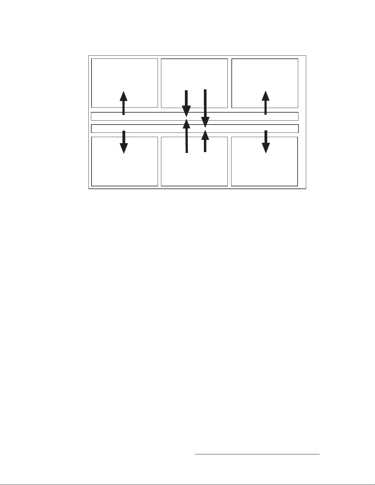
The NV8288 is a standalone router that can manage up to 288 inputs and 576 outputs. Figure 2-1
shows the flow of signals in the NV8288. Both top and bottom crosspoint cards receive all incoming signals, up to 288 inputs. The top crosspoint card feeds signals to output cards located in the
upper half of the router frame: Outputs 1–144 and 145–288. The bottom crosspoint card feeds signals to output cards located in the bottom half of the router frame: outputs 289–432 and 433–576.
on page 15.
4 Rev 1.5 • 24 Sep 09
Page 15
2. Introduction
Signal Rates and Flow
Outputs 1-144 Inputs 1-144
Crosspoint Card
Crosspoint Card
Outputs 289-432 Inputs 145-288
Figure 2-1. Signal Flow for NV8288 (288 inputs and 576 outputs)
(Outputs 1-288)
(Outputs 289-576)
Outputs 145-288
Outputs 433-576
NV8288-Plus
The NV8288-Plus may be used as a standalone router capable of managing up to 288 inputs and
288 outputs or be connected to another NV8288-Plus router to double the number of inputs and
outputs managed to 576 inputs and 576 outputs.
As a standalone router, all incoming signals are sent to all installed crosspoint card(s). (Only one
crosspoint card is required in standalone mode, installed in the top crosspoint slot.) The crosspoint
card feeds outgoing signals to all output cards, up to 288 signals.
If two NV8288-Plus routers are connected together (Router 1, Router 2), each router must contain
two crosspoint cards, installed in the top and bottom crosspoint slots. On each router, incoming signals are sent to both the top and bottom crosspoint cards. The top crosspoint card feeds signals to
all output cards on the local router (router 1), up to 288 signals. The bottom crosspoint card feeds
signals to the connected router (router 2), up to 288 signals. This means that both routers are managing up to 288 incoming signals and 288 outgoing signals for a combined total of up to 576 inputs
and 576 outputs.
NV8288 and NV8288-Plus Digital Video Routers • User’s Guide 5
Page 16
2. Introduction
Power Supply
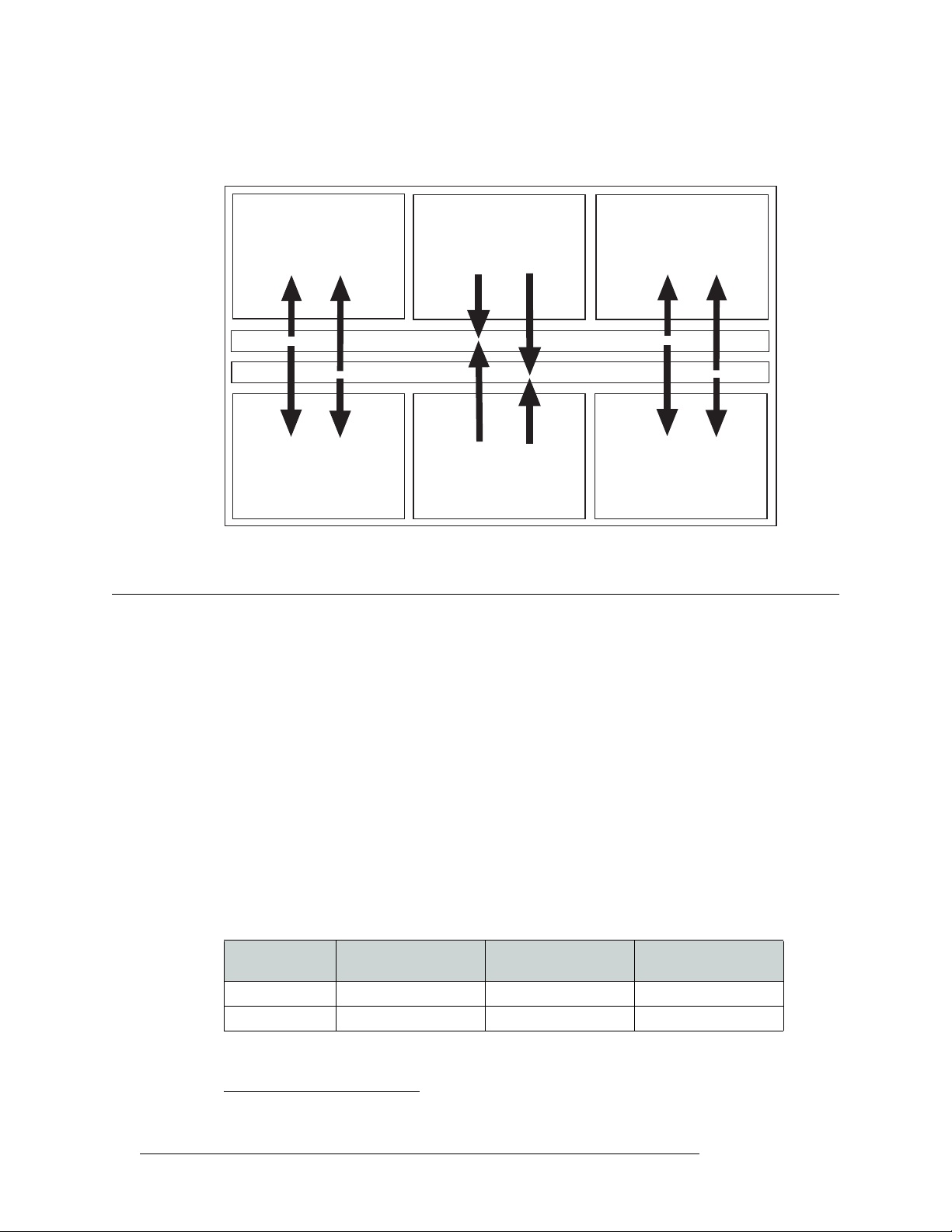
Figure 2-2 shows the flow of signals in the NV8288-Plus when connected to another NV8288-Plus
router.
Figure 2-2. Signal Flow for NV8288-Plus (576 inputs and 576 outputs)
Power Supply
The power supply for the NV8288 and the NV8288-Plus is an external, separate frame. There are
two external power frames available: the NV6257
uses a specific power supply module that supplies power to the router frame.
Outputs 1-72 Inputs 1-144
Router 1
Router 1
Outputs 145-216
Router 2
Crosspoint Card
Crosspoint Card
Router 2
Inputs 145-288
Outputs 73-144
Router 1
(Outputs 1-288)
(Outputs 289-576)
Router 1
Outputs 217-288
1
and the NV8000. Each power supply frame
Router 2
Router 2
Each external power frame uses the following module:
• The NV6257 uses the PS6000 power supply module and can house up to 8 modules.
• The NV8000 uses the PS8010 power supply module and can house up to 4 modules.
The power supply modules differ in the amount of power produced: The PS6000 produces 660
Watts while the PS8010 produces 875 Watts. Because the PS8010 produces a greater amount of
power, fewer modules are needed, reducing the frame size amount of facility space required.
The number of power supply modules required depends on which and how many routers are being
used. For redundancy, additional (optional) power supply modules can be installed.
The minimum number of required power supply modules are as follows:
Two NV8288-Plus
Power Supply One NV8288 One NV8288-Plus
PS6000 4 required, 4 optional 2 required, 2 optional 4 required, 4 optional
PS8010 2 required, 2 optional 2 required, 2 optional 4 required, 4 optional
1. The NV6257 is older. Newer NV8288 and NV8288-Plus routers ship with the NV8000 power supply.
6 Rev 1.5 • 24 Sep 09
Connected
Page 17
2. Introduction
Module Slots and Rear Connectors
The PS6000 and PS8010 power supply modules accepts a wide range of AC input voltages and
produces five +48 VDC outputs. The power supply automatically senses the AC input voltage (90–
130 and 180–250 VAC) and adjusts to maintain a relatively constant DC output; no voltage selection is required.
The five regulated outputs are directed to modules in the router where on-board regulators produce
the DC voltages required by the local circuits. Each +48 VDC output powers one of the five green
LEDs and output test points located on the front of the PS6000 and PS8010 power supply modules.
Under normal operation, all five LEDs are lit. For more information on LEDs, see Indicator LEDs
on page 58.
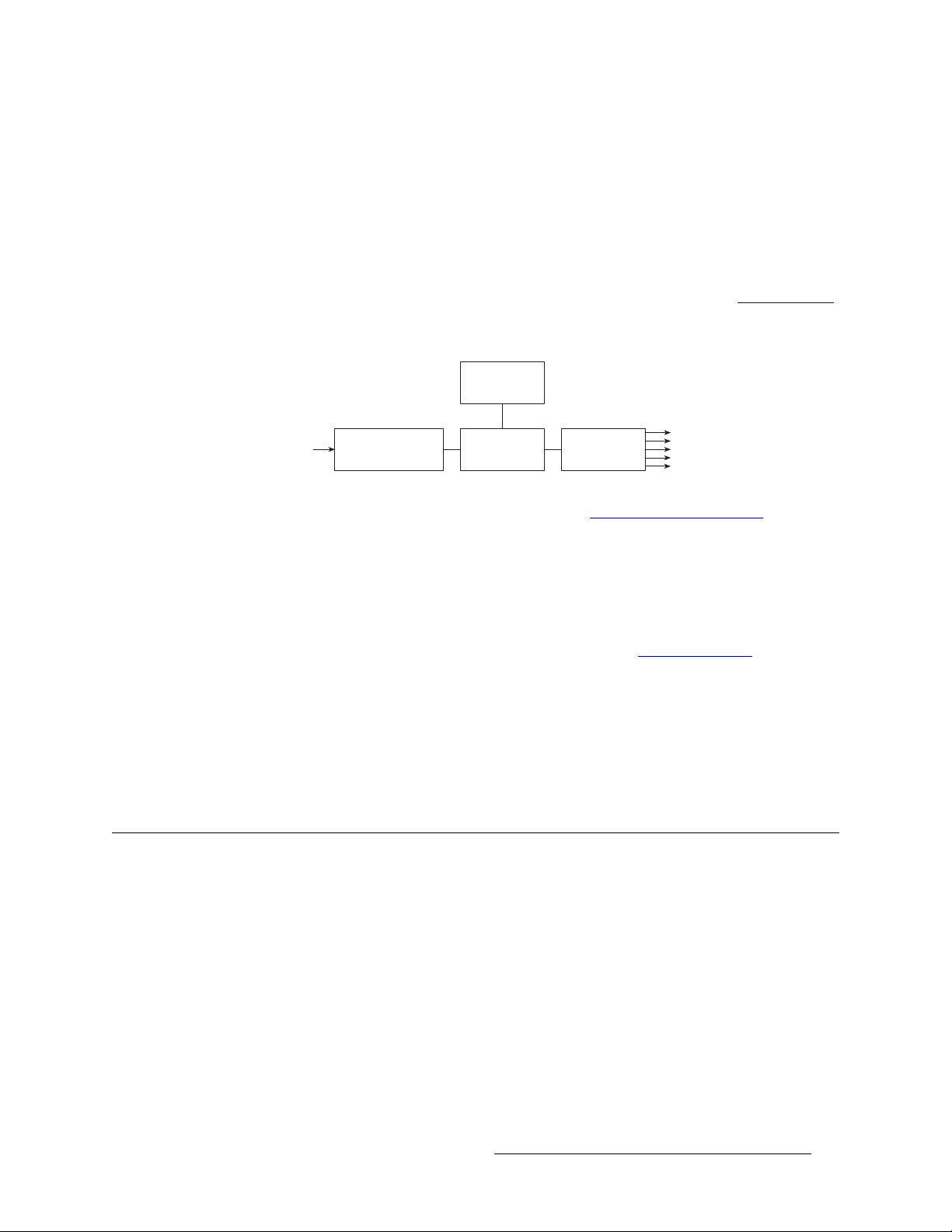
Figure 2-3 shows the PS6000 and the PS8010 power supply module architecture.
Power Sense
and Limiting
90130VAC or
180250VAC In
Figure 2-3. Power Supply Module Diagram
AC Input, Fuse,
Rectifiers, and Filter
For information on making power supply connections, see Making Power Connections on page 24.
Fuses
Fuses for AC power inputs are located on the PS6000 power supply modules. When an NV6257 is
ordered, fuses appropriate for line voltage in use at the country of destination are installed on the
PS6000 power supply modules. Be sure to check the fuse ratings for compliance with specific
requirements in your area. For information on replacing fuses, see Fuse Replacement
The PS8010 power supply module has no serviceable fuses.
Power Supply Cooling
There are four low-speed fans located along the front edge of each PS6000 and PS8010 power supply module. They are intended to pull a small quantity of air across the internal heat sinks.
Module Slots and Rear Connectors
The NV8288 and the NV8288-Plus share common hardware features. Both provide slots for housing input, output, monitor, control and crosspoint cards. Similarly, both feature non-interchangeable
backplanes that house connectors for incoming and outgoing signals. Both also share common system connections. However, the NV8288-Plus has unique output cards and output signal connections that enable two NV8288-Plus routers to be connected together to create a system capable of
managing 576 inputs and 576 outputs.
Power Factor
Correction
+48VDC
Regulators (×5)
+48VDC
Out (×5)
on page 57.
NV8288
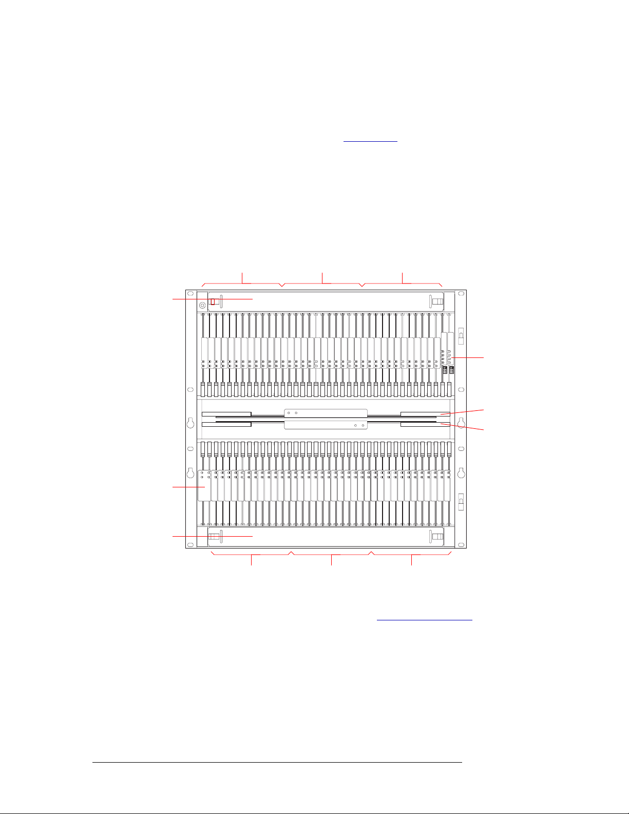
Figure 2-4, next page, shows the front of the NV8288 with the door removed. From this view—in
the slots that do not have an active card installed—the backside of installed backplanes and the
motherboard connectors are visible. The router features 36 upper bay slots and 36 lower bay slots
NV8288 and NV8288-Plus Digital Video Routers • User’s Guide 7
Page 18
2. Introduction
Module Slots and Rear Connectors
for input cards and output cards. In the upper bay are two additional slots for two control cards. In
the lower bay are two additional slots for one monitor cardset (composed of two monitor cards).
Slots contain color-coded card guides that match the color of the ejector lever on the card that is
installed in that slot. For more information, see Active Cards
Located in the center of the router are two horizontal slots housing two crosspoint cards. At the top
and bottom of the router frame are two removable fan trays.
Each input card slot and output card slot, and the card it holds, manages signals received or distributed through 12 connectors. Each signal is assigned a number that corresponds to the physical input
or output connection. This means that Output Slot 1 corresponds to outputs 1-12, Output Slot 2 corresponds to outputs 13-24, and so on, up to 576. Similarly, Input Slot 1 corresponds to inputs 1-12,
Input Slot 2 corresponds to inputs 13-24, and so on, up to 288.
Fan Tray
Output Cards (12)
Outputs 1–144
Input Cards (12)
Inputs 1–144
on page 15.
Output Cards (12)
Outputs 145–288
Control Cards (2)
Crosspoint Cards (2):
Top Card (1–288)
Bottom Card (289–576)
Monitor
Module (1)
Fan Tray
Output Cards (12)
Outputs 289–432
Figure 2-4. NV8288 Router with Door Removed (Front View)
Input Cards (12)
Inputs 145–288
Output Cards (12)
Outputs 433–576
For information on installing cards in module slots, see Installing Active Cards on page 33.
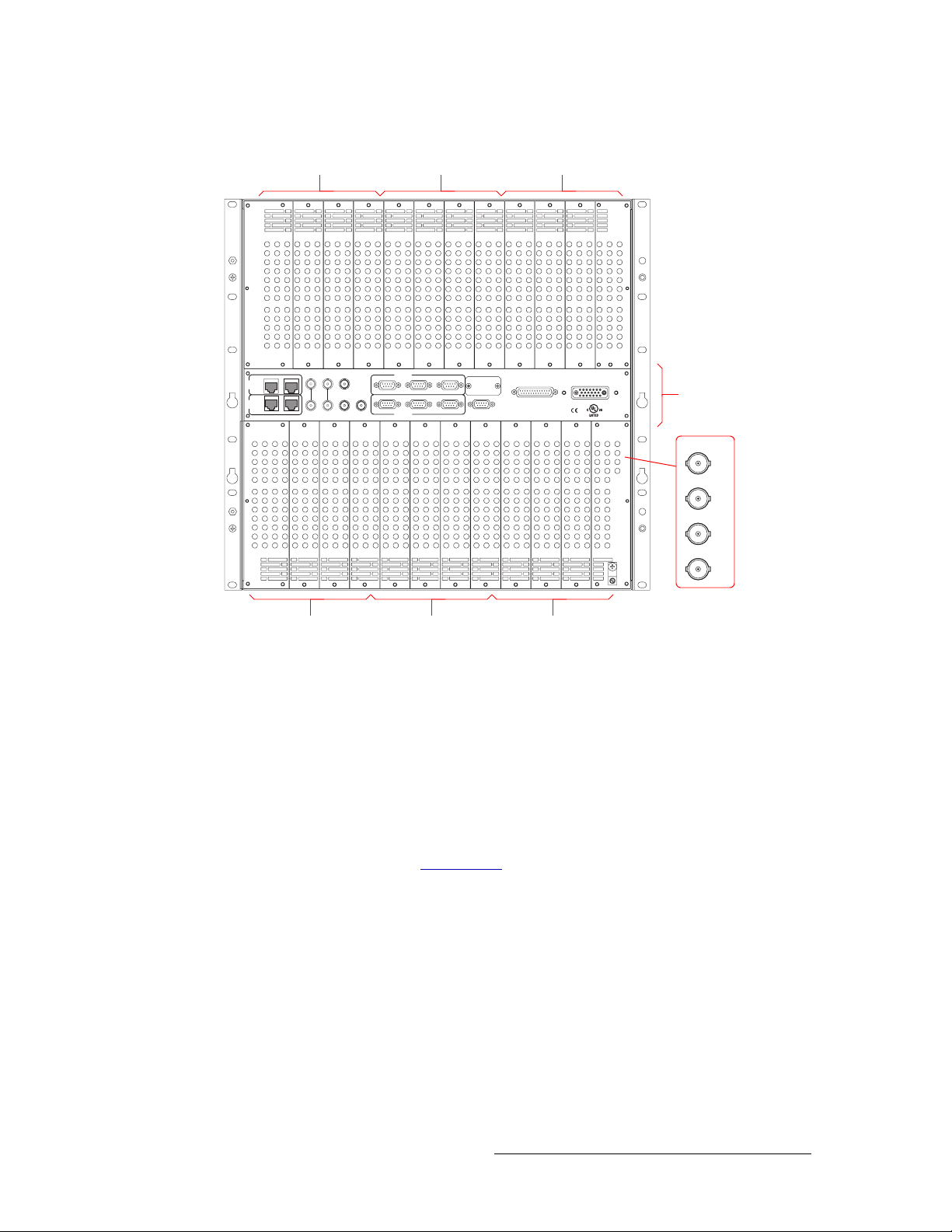
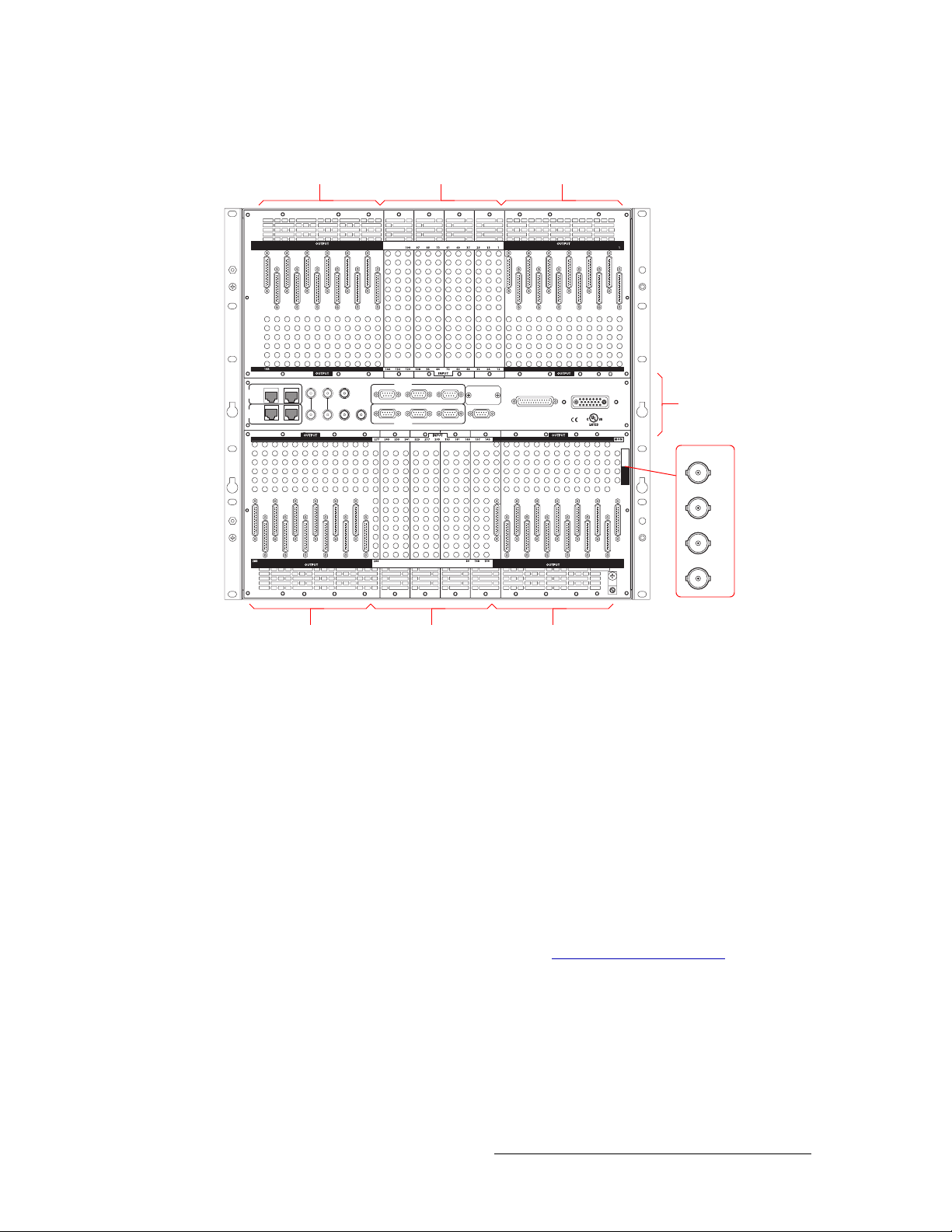
Figure 2-5 shows the rear of the NV8288. The rear contains non-interchangeable backplanes containing 864 I/O DIN 1.0/2.3 connections: 288 for receiving signals and 576 for distributing signals.
Note that the outputs and inputs are numbered from right to left because the router is being viewed
from the rear.
An additional set of four DIN 1.0/2.3 connections, located in the lower, right quadrant, monitor signals. In the center region are connections for system and power functions, as shown in Figure 2-8
on page 12.
8 Rev 1.5 • 24 Sep 09
Page 19
2. Introduction
Module Slots and Rear Connectors
Output Connectors
Outputs 288–145
RTR EXPANSION
10/100BT
PRI
CTRL
SEC
CTRL
10/100BT RTR EXPANSION
Input Connectors
Inputs 144–1
VIDEO
VIDEO
REF 1
REF 2
AUX 1
PRI CTRL
CTRL 1
DIAG (38.4 Kbaud)
CTRL 2
Output Connectors
Outputs 144–1
POWER SUPPLY
MONITORS
POWER INPUT
System and Power
CTRL 1
LOOP
LOOP
AUX 2
TIME
CODE
SEC CTRL
CTRL 2
DIAG (38.4 Kbaud)
ALARMS
E146905
Connectors
IN 1
IN 2
OUT 1
OUT 2
Monitor Connectors
Output Connectors
Outputs 576–433
Input Connectors
Inputs 288–145
Output Connectors
Outputs 432–289
Figure 2-5. NV8288 Router (Rear View)
NV8288-Plus
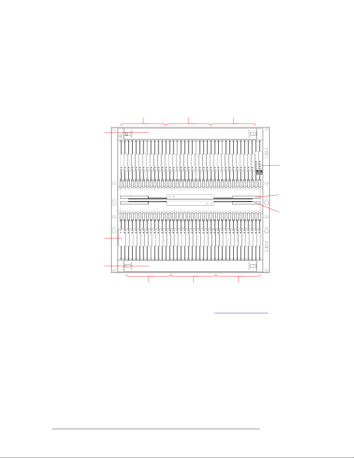
Figure 2-6 on page 10 shows the front of the NV8288-Plus with the door removed. From this view,
in the slots that do not have an active card installed, the backside of installed backplanes and the
motherboard connectors are visible. The router features 36 upper bay slots and 36 lower bay slots
for input cards and output cards. In the upper bay are two additional slots for two control cards. In
the lower bay are two additional slots for one monitor cardset (composed of two monitor cards).
Slots have colored guides that match the color of the ejector lever on the card that is installed in that
slot. For more information, see Active Cards
Located in the center of the router are two horizontal slots housing two crosspoint cards. At the top
and bottom of the router frame are two removable fan trays.
Inputs are numbered 1–288 with each card slot, and the card it holds, corresponding to 12 input
connections. This means that input slot 1 corresponds to inputs 1–12, input slot 2 corresponds to
inputs 13–24, and so on, up to 288.
Outputs are numbered 1–288 also, but each card slot contains two types of output connections: 6
connections for outgoing signals for the local router and one expansion connection for outputs to a
connected NV8288-Plus router. This means that output slot 1 corresponds to outputs 1–6, output
slot 2 corresponds to outputs 7–12, and so on, up to 288.
on page 15.
NV8288 and NV8288-Plus Digital Video Routers • User’s Guide 9
Page 20
2. Introduction
Module Slots and Rear Connectors
If the NV8288-Plus router is used as a standalone router, only the 6 local outgoing signal connections are used. If the router is connected to another NV8288-Plus router, each expansion connection
send signals to the connected router, as follows: output slot 1 sends outputs 289–294 to the connected router, output slot 2 sends outputs 295–300 to the connected router, and so on, up to 576.
Similarly, the connected router sends outputs to the local router in the same manner, doubling outputs. Inputs are also doubled, so that the two routers have a combined total of 576 inputs and 576
outputs.
Fan Tray
Output Cards(12)
Outputs 1–72
Input Cards (12)
Inputs 1–144
Output Cards (12)
Outputs 73–144
Control Cards (2)
Crosspoint Cards (2):
Top Card for local
outputs 1–288
Bottom Card for external
outputs 1–288
Monitor
Module (1)
Fan Tray
Output Cards (12)
Outputs 145–216
Figure 2-6. NV8288-Plus Router with Door Removed (Front View)
Input Cards (12)
Inputs 145–288
Output Cards (12)
Outputs 217–288
For information on installing cards in modules slots, see Installing Active Cards on page 33.
The rear of the NV8288-Plus (Figure 2-7, next page) features non-interchangeable backplanes containing 288 I/O DIN 1.0/2.3 connections for receiving signals and 288 DIN 1.0/2.3 connections for
distributing signals, plus 48 expansion connections for sending signals between two connected
NV8288-Plus routers. By connecting two routers you can receive and distribute up to 576 signals.
Note that the outputs and inputs are numbered from right to left because the router is being viewed
from the rear.
10 Rev 1.5 • 24 Sep 09
Page 21
2. Introduction
E
I
E
Module Slots and Rear Connectors
xpansion and
Output Connectors
Outputs 144–73
120
132
126
831 108
RTR EXPANSION
10/100BT
PRI
CTRL
SEC
CTRL
10/100BT RTR EXPANSION
270276
258264 222
282
nput
Connectors
Inputs 144–1
79859197103109115121127133139 73 713192531374349556167
114
VIDEO
VIDEO
REF 2
REF 1
7
849096102 8
AUX 1
PRI CTRL
CTRL 1
DIAG (38.4 Kbaud)
CTRL 2
xpansion and
Output Connectors
Outputs 72–1
36424854606672
POWER SUPPLY
MONITORS
POWER INPUT
12182430 6
System and Power
CTRL 1
LOOP
AUX 2
LOOP
TIME
CODE
223229235241247253259265271277283 217
234240
228
246252
SEC CTRL
CTRL 2
DIAG (38.4 Kbaud)
ALARMS
175 169 151157163 145181187193199205211
156162168174180186192198204210216 150
E146905
IN
1
IN
2
OUT
1
OUT
2
Connectors
IN 1
IN 2
OUT 1
OUT 2
Monitor Connectors
Expansion and
Output Connectors
Outputs 288–217
Figure 2-7. NV8288-Plus Router (Rear View)
Input
Connectors
Inputs 288–145
Expansion and
Output Connectors
Outputs 216–145
System Connections
Both the NV8288 and the NV8288-Plus feature connections for managing system functions. These
connections enable you to connect to:
• A router control system using either Ethernet or serial connectors.
• A stable source of video signal for reference purposes.
• The UniConfig application, installed on a PC, used to perform configuration tasks.
• The system alarm that sends notification of a system failure, such as a fan malfunction or power
supply failure.
• The NV6257 or the NV8000 power supply. (See Making Power Connections
Figure 2-8 shows the system and power connections. The ‘AUX’ and ‘TIME CODE’ connections
are not used at this time and not discussed in this manual.
on page 24.)
NV8288 and NV8288-Plus Digital Video Routers • User’s Guide 11
Page 22
2. Introduction
Module Slots and Rear Connectors
RTR EXPANSION
Video
Ref.
VIDEO
VIDEO
REF 2
REF 1
LOOP
AUX 1
LOOP
AUX 2
Aux, Time Code Ref.
(Not Used)
Serial Control
(to Control System
PRI CTRL
CTRL 1
CTRL 1
TIME
CODE
SEC CTRL
CTRL 2
CTRL 2
Diagnostic
DIAG (38.4 Kbaud)
DIAG (38.4 Kbaud)
Port s
Power Supply Monitor
ALARMS
System
Alarms
(from NV6257)
POWER SUPPLY
MONITORS
POWER INPUT
E146905
Power Connection
(from NV6257)
Ethernet, to
control system
10/100BT
PRI
CTRL
SEC
CTRL
10/100BT RTR EXPANSION
Expansion port,
to other router
(NV8288-Plus only)
Figure 2-8. System and Power Connections for the NV8288 and the NV8288-Plus (Rear View)
Router Control System Connections
Router control systems are usually run on a separate PC, which is then connected to the router. The
router provides two different ways to connect to a router control system: serial or Ethernet. The
router control system being used determines which connection is used. For example, to connect to
the NV9000 control system an Ethernet connection is preferred.
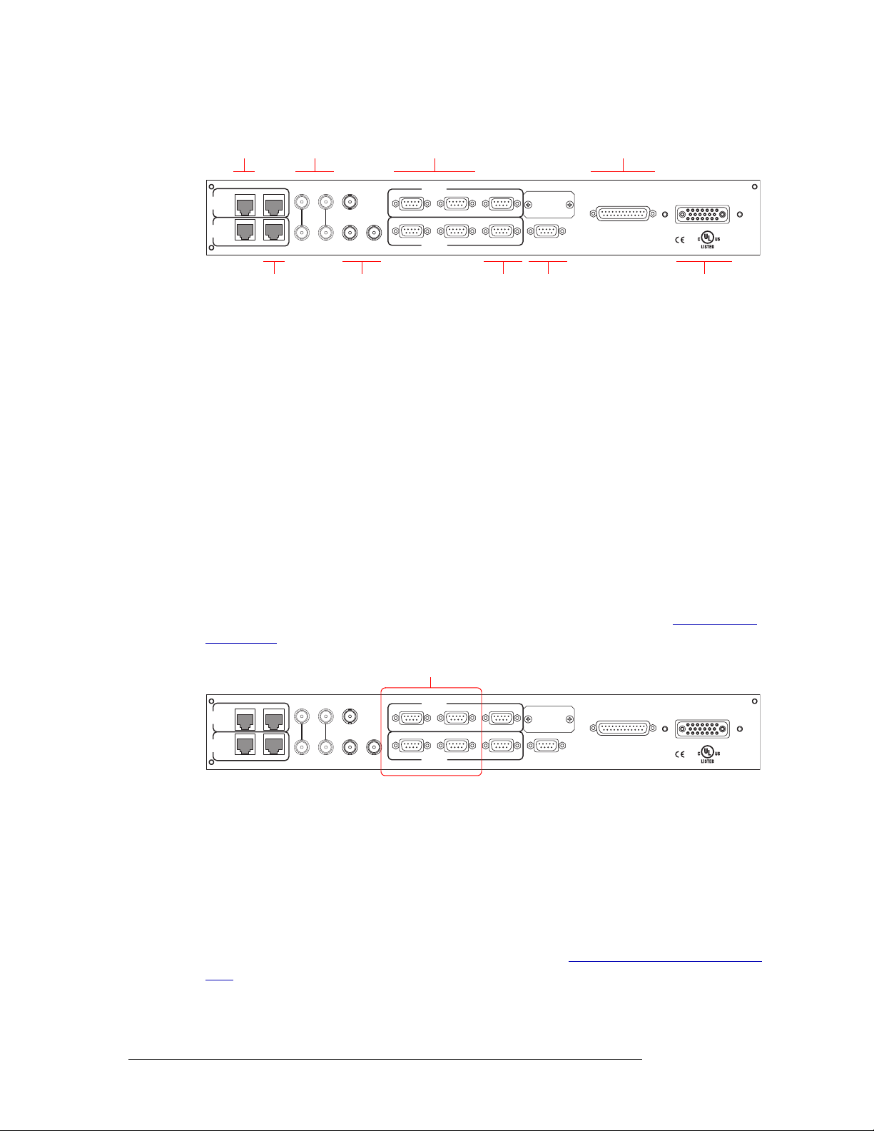
Serial Control Connections
The router has four serial ports, as shown in Figure 2-9. The ports are divided into two sets, one primary (‘PRI CTRL’) and one secondary (‘SEC CTRL’). Primary control is the connection to the primary control card. Secondary control is the connection to the secondary (optional for redundancy)
control card. Each set is further divided into connections that correspond to router control systems:
‘CTRL 1’ corresponds to the primary control system and ‘CTRL 2’ corresponds to an alternate
control system. Using ‘CTRL 2’ connections, you can connect to an alternate control system (i.e.,
backup system) or set up dual control, if desired. For installation instructions, see Serial Control
Connections on page 38.
Serial Connections
to Router Control System
VIDEO
CTRL
CTRL
PRI
SEC
RTR EXPANSION
10/100BT
10/100BT RTR EXPANSION
VIDEO
REF 2
REF 1
LOOP
AUX 1
LOOP
AUX 2
TIME
CODE
PRI CTRL
CTRL 1
CTRL 1
SEC CTRL
DIAG (38.4 Kbaud)
CTRL 2
CTRL 2
DIAG (38.4 Kbaud)
ALARMS
POWER SUPPLY
MONITORS
POWER INPUT
E146905
Figure 2-9. Serial Connections to Router Control System (Rear View)
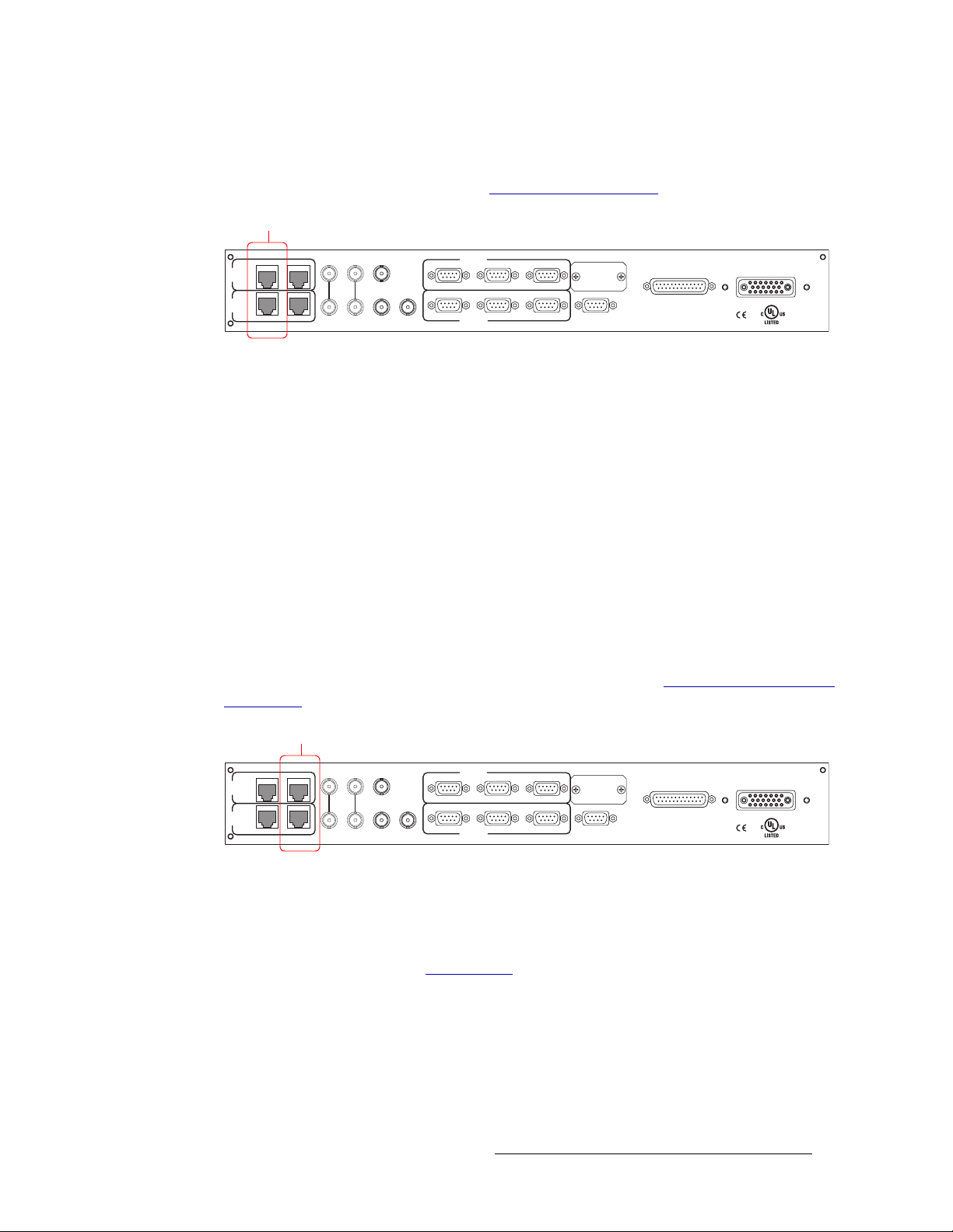
Ethernet Control Connections
The router has two Ethernet ports labeled ‘10/100BT’, as shown in Figure 2-10 on page 13. The
ports are divided into two sets, one primary (‘PRI CTRL’) and one secondary (‘SEC CTRL’). Primary control is the connection to the primary control card. Secondary control is the connection to
the secondary (optional for redundancy) control card. One port is for primary control (‘PRI
CTRL’), connecting the local router to the control system. Unlike serial connections, there are no
connections to alternate control systems because you can connect to alternate control systems using
Ethernet network connections. For installation instructions, see Ethernet Control System Connec-
tions on page 40.
In order for the router to communicate with the router control system through an Ethernet connection, an IP address for the router needs to be set in the control card. The IP address is set using Uni-
12 Rev 1.5 • 24 Sep 09
Page 23
2. Introduction
Module Slots and Rear Connectors
Config. However, UniConfig is also run on a PC and similarly cannot communicate with the router
until an IP address is entered. Therefore, a connection to the PC running UniConfig needs to be created using a serial connection: serial. (See Serial Control Connections
Ethernet Connections
to Router Control System
VIDEO
CTRL
CTRL
PRI
SEC
RTR EXPANSION
10/100BT
10/100BT RTR EXPANSION
VIDEO
REF 2
REF 1
LOOP
AUX 1
LOOP
AUX 2
TIME
CODE
PRI CTRL
CTRL 1
CTRL 1
SEC CTRL
DIAG (38.4 Kbaud)
CTRL 2
CTRL 2
DIAG (38.4 Kbaud)
ALARMS
Figure 2-10. Ethernet Connections to Router Control System (Rear View)
Control System Expansion Connections
In order to manage two connected NV8288-Plus routers, control system expansion connections
need to be connected between the routers. Expansion control system connections are located on the
rear of the router, as shown in Figure 2-11.
When making control system connections, only one router is directly to the control system. This
router acts as the primary router. When making control system expansion connections, connections
from the remaining router, the secondary router, are made to the primary router. This enables the
router control system to communicate with both routers through the primary router.
on page 38.)
POWER SUPPLY
MONITORS
POWER INPUT
E146905
There are two control system expansion connections, labeled ‘RTR Expansion’. The ports are
divided into two sets, one primary (‘PRI CTRL’) and one secondary (‘SEC CTRL’). Primary control is the connection to the primary control card. Secondary control is the connection to the secondary (optional for redundancy) control card. One port is for primary control (‘PRI CTRL’),
connecting the local router to the control system.
For instructions on making control system expansion connections, see Control System Expansion
Connections on page 40.
Expansion Connections
to Other Router
VIDEO
CTRL
CTRL
PRI
SEC
RTR EXPANSION
10/100BT
10/100BT RTR EXPANSION
VIDEO
REF 2
REF 1
LOOP
AUX 1
LOOP
AUX 2
TIME
CODE
PRI CTRL
CTRL 1
CTRL 1
SEC CTRL
DIAG (38.4 Kbaud)
CTRL 2
CTRL 2
DIAG (38.4 Kbaud)
ALARMS
POWER SUPPLY
MONITORS
POWER INPUT
E146905
Figure 2-11. Expansion Control System Connections (Rear View)
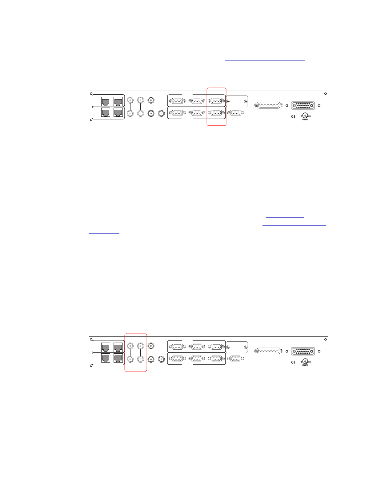
Diagnostic Connections
The diagnostic connections enable the router to communicate with the UniConfig application. UniConfig runs on a PC separate from the router and is used to perform system setup tasks, and configure and monitor the router. (See Configuration
UniConfig, see the UniConfig User’s Guide.
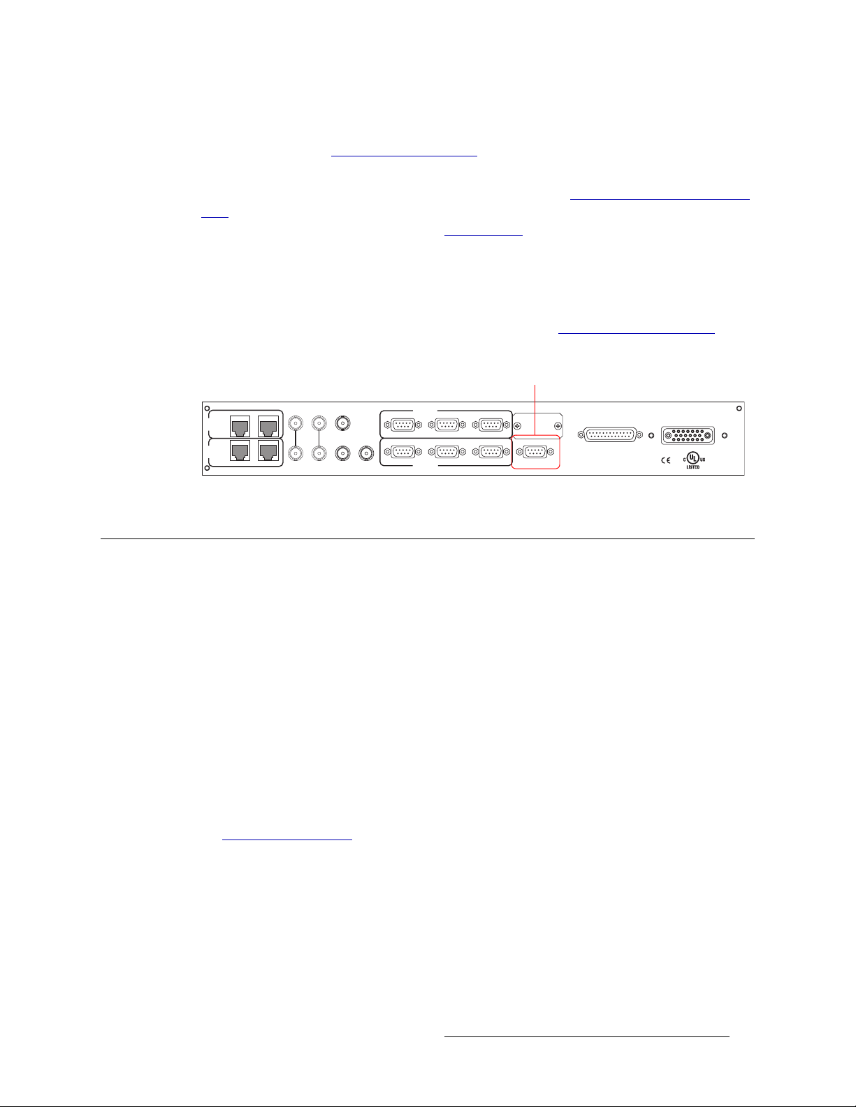
Diagnostic connections connect the router to the PC running the UniConfig application. Two diagnostic connections are located on the rear of the router, labeled ‘DIAG’. The ports are divided into
two sets: one primary (‘PRI CTRL’) and one secondary (‘SEC CTRL’), as shown in Figure 2-12.
The primary control connects to the primary control card. The secondary control connects to the
secondary (optional for redundancy) control card.
on page 53.) For information about using
NV8288 and NV8288-Plus Digital Video Routers • User’s Guide 13
Page 24
2. Introduction
Module Slots and Rear Connectors
For instructions on making diagnostic connections, see Making Diagnostic Connections on
page 41.
RTR EXPANSION
10/100BT
PRI
CTRL
SEC
CTRL
10/100BT RTR EXPANSION
Figure 2-12. Permanent Diagnostic Connections (Rear View)
Video Reference
The NV8288 and the NV8288-Plus provide timing reference connections for video signals, labeled
‘VIDEO REF 1’ and ‘VIDEO REF 2’, as shown in Figure 2-13 on page 14. Located on the rear of
the router, these connections provide a reference input for determining the router’s video frame
switch point. The video reference connections require a stable source of PAL, NTSC or Tri-level
sync.
If a video reference is present, signals switch at the defined frame and line switch points. If a video
reference is not present, the router still performs the switch, but to an internal reference. If a video
reference is not connected, the control card displays a lit red LED. (See Indicator LEDs
page 58.) For instructions on making video reference connections, see Making Video Reference
Connections on page 43.
Diagnostic
Connections
VIDEO
VIDEO
REF 1
REF 2
AUX 1
LOOP
LOOP
AUX 2
TIME
CODE
PRI CTRL
CTRL 1
CTRL 1
SEC CTRL
DIAG (38.4 Kbaud)
CTRL 2
DIAG (38.4 Kbaud)
CTRL 2
ALARMS
POWER SUPPLY
MONITORS
POWER INPUT
E146905
on
Redundant and Dual References
There are two video reference connections. The same reference can be used for both connections or
a different reference for each connection. When using the same, or “redundant,” references for both
connections, if one reference fails, the control card fails-over to the redundant reference. When
using different references, or “dual” references, switch takes can occur based on one or the other
reference. For example, if ‘VIDEO REF 1’ uses NTSC as a reference and ‘VIDEO REF 2’ uses
PAL as a reference. Using UniConfig, the type of setting is selected: redundant or dual, and if dual,
which outputs reference which video reference on an output by output basis. (See the UniConfig
User’s Guide.)
Video Reference
Connectors
VIDEO
CTRL
CTRL
PRI
SEC
RTR EXPANSION
10/100BT
10/100BT RTR EXPANSION
VIDEO
REF 1
REF 2
AUX 1
LOOP
LOOP
AUX 2
TIME
CODE
PRI CTRL
CTRL 1
CTRL 1
SEC CTRL
DIAG (38.4 Kbaud)
CTRL 2
CTRL 2
DIAG (38.4 Kbaud)
ALARMS
POWER SUPPLY
MONITORS
POWER INPUT
E146905
Figure 2-13. Connections to Video References (Rear View)
System Alarm
The NV8288 and the NV8288-Plus provide a system alarm that sends notification a malfunction,
such as when a fan or power supply is not functioning properly. The NV6257 (power supply) and
the NV8288 each have alarm connections that can be connected to external equipment that display
visual signals when an alarm is activated. Creation of an external alarm indicator is outside the
14 Rev 1.5 • 24 Sep 09
Page 25
2. Introduction
Active Cards
scope of this manual, however basic instructions on wiring the alarm connection for external monitoring is provided. See External Alarm Indicators
In addition to an alarm connection, the NV8288 is connected to a router control system that
receives status information from the router’s control card(s). (See Router Control System Connec-
tions on page 12.) The control card reads the status of NV6257’s power supply and fans through the
‘Power Supply Monitors’ connection. (See Power Supply
monitors the router’s power supply, fans, and video reference connections. Both NV6257 and
router information is communicated to the router control system and viewable using UniConfig.
(See the UniConfig User’s Guide.)
The alarm connection is labeled ‘ALARM’ and is located on the rear of the router, as shown in
Figure 2-14. For instructions on making alarm connections, see Making Alarm Connections
page 47.
VIDEO
CTRL
CTRL
PRI
SEC
RTR EXPANSION
10/100BT
10/100BT RTR EXPANSION
VIDEO
REF 1
REF 2
AUX 1
LOOP
LOOP
AUX 2
TIME
CODE
PRI CTRL
CTRL 1
CTRL 1
SEC CTRL
CTRL 2
CTRL 2
on page 48.
on page 6.) In addition, the control card
System Alarm
Connector
DIAG (38.4 Kbaud)
DIAG (38.4 Kbaud)
ALARMS
POWER SUPPLY
MONITORS
on
POWER INPUT
E146905
Figure 2-14. System Alarm Connection (Rear View)
Active Cards
The NV8288 and the NV8288-Plus feature several active cards that manage incoming signals, forwarding of commands from the control system, perform signal switching, and distribute outgoing
signals. Each card has a colored ejector lever that matches the colored card guide on the slot into
which the card is installed.
The NV8288 and the NV8288-Plus both feature:
Each card and function is described in the following section. For information on installing cards,
see Installing Active Cards
Control Cards
• 1 or 2 control cards (one optional for redundancy)
• 24 input cards
• 48 output cards
• 1 or 2 crosspoint cards (depending on configuration)
• 1 monitor cardset (composed of 2 cards)
on page 33.
The router has two control cards (EM0529), one primary and one secondary (optional for redundancy). Each card receives commands from the control system (e.g., NV9000), and in turn, controls
the input, output, crosspoint and monitor cards. Only one control card is active at a time, with the
active card updating the stand-by card.
NV8288 and NV8288-Plus Digital Video Routers • User’s Guide 15
Page 26
2. Introduction
Active Cards
The control card includes a status reporting circuit. Four LEDs on the front of the control card indicate the card’s status: low battery (Red), alarm (Red), active (Amber) and “healthy” (Green). For
more information, see Indicator LEDs
Input Cards
The router frame can house up to 24 standard input cards, each processing up to 12 SD-SDI or 12
SWB signals. Input cards receive incoming signals through connections on I/O backplanes and feed
outputs to the crosspoint cards.
There are two types of input cards available, one for incoming SD-SDI signals and one for incoming SWB signal. Both the NV8288 and the NV8288-Plus can have either input card installed. Each
card is listed by the type of signal it manages
ber for each card has been included. For a detailed description of a card’s function, see Input Card
Functions, following.
on page 58.
— SD or SWB. For your convenience, the part num-
Input Card
Category
Standard SD 259M
Standard SWB 259M
Signal Type
Standard
(SMPTE)
344M
344M
292M
Rates Part Number
143, 177, 270, 360, and 540 Mb/s EM0530
143, 177, 270, 360 and 540
EM0531
Mb/s; 1.483 and 1.485 Gb/s
Input Card Functions
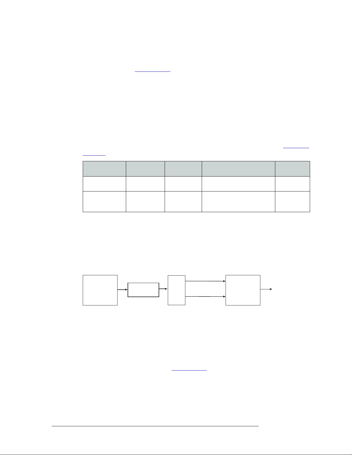
Both input cards contain 12 cable equalizers. Each cable equalizer equalizes the signal and distributes two copies of the signal to the motherboard. The motherboard forwards copies to all installed
crosspoint cards. Because all incoming signals are sent to all crosspoint cards, an incoming signal
can be distributed to any or every output card.
Figure 2-15 shows the flow of a signal through the SD-SDI and SWB input card.
Copy of Signal
Coaxial
Connector
(12)
Figure 2-15. Input Card Block Diagram
Cable
Equalizer
Buffer
Copy of Signal
Motherboard
All crosspoint cards
Status Reporting
All input cards feature a circuit that performs status reporting and drives the card’s functions. Two
LEDs on the front of the input card indicate the card’s status: alarm (Red), power good (Green).
Three additional LEDs situated further back on the card indicate if software is loaded (Amber), if
there is good communication with the control card (Green) or bad communication with the control
card (Red). For more information, see Indicator LEDs
on page 58.
Crosspoint Cards
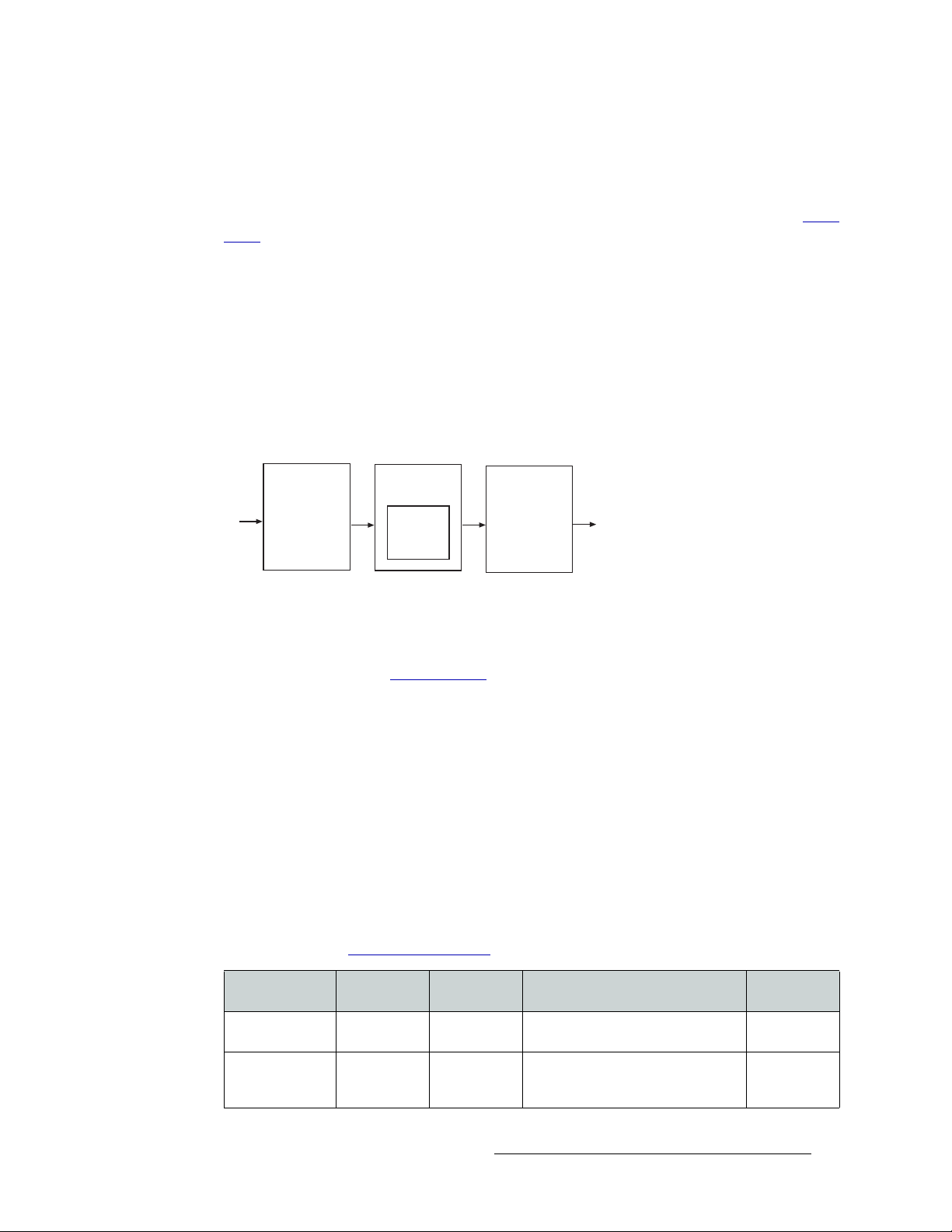
Crosspoint cards (EM0534) receive signals from the input cards (via the motherboard) and commands from the control card. The crosspoint card then performs switching as directed, sending sig-
16 Rev 1.5 • 24 Sep 09
Page 27
2. Introduction
Active Cards
nals to the output cards (via the motherboard). Each crosspoint card can receive and distribute up to
288 signals.
The router can house up to two crosspoint cards. A second crosspoint card is only required to support outputs greater than 288. All installed crosspoint cards receive all incoming signals. (See Input
Cards on page 16.)
Depending on the router being used, crosspoint cards send signals to output cards, as follows:
• NV8288
— The top crosspoint card feeds signals to the output cards located in the upper half of
the frame (outputs 1–288). The bottom crosspoint card feeds signals to the output cards located
in the lower half of the frame (outputs 289–576). See Figure 2-1 on page 5.
• NV8288-Plus
— If two routers are connected, the top crosspoint card feeds signals to all output
cards on the local router (Outputs 1-288). The bottom crosspoint card feeds signals to the connected router (Outputs 289-576). If the router is not connected to a second router, the router
only manages local Outputs 1-288. See Figure 2-2 on page 6.
Figure 2-16 shows the flow of signals through the crosspoint card:
Crosspoint
Card
Motherboard
Input Card
Figure 2-16. Crosspoint Card Block Diagram
Crossbar
Switch
288 x 288
Motherboard
Output Card
The crosspoint card includes a status reporting circuit. Five LEDs on the front of the crosspoint
card indicate the card’s status: alarm (Red), power good (Green), FPGA loaded (Amber), good
communication with the control card (Green) and bad communication with the control card (Red).
For more information, see Indicator LEDs
on page 58.
Output Cards
The router frame can house up to 48 output cards, each processing up to 12 SD or 12 SWB signals.
There are two types of output cards: standard and filler. The NV8288 uses the filler output card
only. The NV8288-Plus uses the standard output card only.
The filler output card manages signals distributed to the coaxial connections. The standard output
card manages signals distributed to the coaxial connections and to the expansion connections when
two NV8288-Plus routers are connected together.
The following is a list of the different output cards available. Each card is listed by the function it
performs (category)
— filler or standard — and the type of signal it manages — SD-SD or SWB. For
your convenience, the part number for each card has been included. For a detailed description of a
card’s function, see Output Card Functions
Standard
Input Card Signal Type
Filler SD 259M
Filler SWB 259M
NV8288 and NV8288-Plus Digital Video Routers • User’s Guide 17
(SMPTE)
344M
344M
292M
on page 18.
Rates Part
143, 177, 270, 360, and 540 Mb/s EM0532
143, 177, 270, 360, and 540 Mb/s;
1.483 and 1.485 Gb/s
EM0533
Page 28

2. Introduction
Active Cards
Input Card Signal Type
Standard SD 259M
Standard SWB 259M
Output Card Functions
Output cards process up to 12 incoming signals. The functions of each type of card are described in
the following sections. Outputs cards are organized by category
Filler
The NV8288 uses filler output cards. There are two types of filler output cards: one for outgoing
SD-SDI signals (EM0532) and one for outgoing SWB signals (EM0533). Both types of cards
receive 12 inputs from the crosspoint card and contain 12 re-clockers. The re-clocker creates two
copies of the input, feeding one output to a cable driver and one output to a 12×1 MUX. The cable
driver forwards the output to the coaxial connector to distribute outgoing signals. The Mux sends
the output to the motherboard, which in turns forwards the output to the monitor cardset for monitoring.
Standard
(SMPTE)
344M
344M
292M
Rates Part
143, 177, 270, 360, and 540 Mb/s EM0540
143, 177, 270, 360, and 540 Mb/s;
1.483 and 1.485 Gb/s
— filler or standard.
EM0541
Figure 2-17 shows the flow of a signal through the filler output card. For signal re-clocking rates,
see Signal Rates and Flow
Monitor
Motherboard
(12)
Crosspoint Card
Figure 2-17. Filler Output Card Block Diagram
on page 4.
12 x 1 Mux
Re-clocker
Cable
Driver
Coaxial
Connector
(12)
Outgoing Signal
Standard
The NV8288-Plus uses standard output cards. There are two types of standard output cards: one for
SD signals (EM0540) and one for SWB signals (EM0541). Each card receives 6 inputs from the
top crosspoint card (via the motherboard). The inputs are fed to a 2×1 MUX, which forwards the
input to one of 6 re-clockers. The re-clocker creates two copies of the input, feeding one output to a
cable driver and one output to a 6×1 MUX. The cable driver forwards the output to the coaxial connector to distribute the outgoing signals. The Mux sends the output to the motherboard, which in
turns forwards the signal to the monitor cardset for monitoring.
When two NV8288-Plus routers are connected together, the top crosspoint card distributes 6 signals as described above, sending one copy to the local coaxial connectors and one copy to the local
monitor cardset. In addition, the bottom crosspoint card on the local router forwards 6 signals to a
cable driver. The cable driver feeds the outputs to the expansion connection for distribution to the
connected router. At the same time, the connected router sends 6 signals to the local router through
the expansion connections. Signals arriving from the connected router through the expansion connections are forwarded to one of 6 cable receivers. The cable receivers forward the signal to the
18 Rev 1.5 • 24 Sep 09
Page 29

2. Introduction
Active Cards
local 2×1 Mux, which in turn feeds the signals to one of 6 reclockers. The reclocker creates two
copies of the input, feeding one output to a cable driver and one output to a 6×1 MUX. The cable
driver forwards the output to the coaxial connector to distribute outgoing signals. The Mux sends
the output to the motherboard, which in turns forwards the signal to the monitor cardset for monitoring.
Standard output cards on the local router and standard output cards on the connected router “mirror” each other, performing identical tasks. To illustrate, the standard output cards receive and distribute signals as follows, where Router 1 is the local router and Router 2 is the connected router:
• Router 1 receives 6 signals from the top crosspoint card (one copy of the local input). These
signals are sent to both the monitor cardset and to coaxial connectors as outgoing signals
• Router 1 receives 6 signals from the bottom crosspoint card (one copy of the local input). These
signals are sent to the expansion connections and forwarded to Router 2.
• Router 1 receives 6 signals from Router 2 through the expansion connections.
• At the same time, Router 2 performs the exact same tasks Router 1 is performing.
Figure 2-18 shows the flow of a signal through the standard output card. For signal re-clocking
rates, see Signal Rates and Flow
on page 4.
Monitor
Motherboard
Card
Top Crosspoint
Card
Bottom Crosspoint
Figure 2-18. Standard Output Card Block Diagram
(6)
Motherboard
(6)
6 x 1 Mux
2 x 1 Mux
Re-clocker
Cable
Driver
Cable
Driver
Cable
Receiver
Coaxial
Connector
(6)
Expansion
Cable
Connector
(6)
Outgoing Signal
From Expansion
Cable
Output to
Expansion Cable
Status Reporting
All output cards feature a circuit that performs status reporting and drives the card’s functions. Five
LEDs on the front of the output card indicate the card’s status: alarm (Red), power good (Green),
FPGA loaded (Amber), good communication with the control card (Green) and bad communication
with the control card (Red). For more information, see Indicator LEDs
on page 58.
Monitor Card Set
A monitor cardset (EM0546), composed of two cards, receives one signal from each output card
and then sends two outgoing signals. These outgoing signals can be sent to monitoring equipment
for the purpose of monitoring outgoing signal quality.
NV8288 and NV8288-Plus Digital Video Routers • User’s Guide 19
Page 30

2. Introduction
Frame Expansion
There are two monitor connections: one for SD signals and one for SWB signals. Using UniConfig,
you can set up a SD level and a SWB level and monitor both simultaneously through the control
system. For more information on setting up levels, see the UniConfig User’s Guide.
When two NV8288-Plus routers are connected together, the two monitor outputs from one router
are forwarded to the two monitor inputs on the second, connected router through monitor expansion
connections. This enables the monitoring of all outgoing signals from both routers through a single
set of monitoring connections.
For information on making monitor connections, see Making Monitor Connections
Frame Expansion
Using the NV8288-Plus router, you can connect two router frames together to create a switching
matrix up to 576 inputs and 576 outputs. The two frames are linked by connecting several expansion connections on one router to expansion connections on the second router.
The expansion connections are:
• I/O Signals
the two routers. All 48 connections must be connected. See Signal Expansion Connections
page 35.
•Control System
system expansion connections, control system connections are also made between the two routers. This enables the control system to see both routers through one control system connection.
See Control System Expansion Connections
• Monitoring Equipment
monitor expansion connections, monitor connections are also made between the two routers.
This enables the monitoring equipment to see both routers through one monitor connection. See
Monitor Expansion Connections
Each router must have two crosspoint cards installed. (See Crosspoint Cards
two frames are connected together, the top crosspoint card on each router sends output signals to all
distributing I/O connections. The bottom crosspoint card on each router sends output signals to the
connected router (i.e., Router 1 sends signals to Router 2; Router 2 sends signals to Router 1). For
more information on how signals flow within and between connected routers, see NV8288-Plus
page 5.
on page 44.
— Each frame has 48 signal expansion connections. Connections are made between
on
— One router is connected directly to the router control system. Using control
on page 40.
— One router is connected directly to the monitoring equipment. Using
on page 45.
on page 16.) When
on
Figure 2-19 shows the flow of signals between two connected routers. The signals are forwarded to
the connected router through the expansion output cards. For details on how the expansion output
cards manage inputs from the expansion connections, see Standard
Expansion
Output
Card
Router 1
Figure 2-19. Frame Expansion Diagram
20 Rev 1.5 • 24 Sep 09
Expansion
Cable
Connector
Router 1
x 6
Expansion
Cable
Connector
Router 2
on page 18.
Expansion
Output
Card
Router 2
Page 31

3. Installation
Chapter 3 provides installation and connection instructions. It presents the following topics:
Summary
• Package Contents
• Preparing for Installation
• Rack Mount
• Making Power Connections
• Installing Active Cards
• Making Signal Connections
• Making Router Control System Connections
• Making Diagnostic Connections
• Making Video Reference Connections
• Making Monitor Connections
• Making Alarm Connections
• Verification
When setting up the NV8288 or the NV8288-Plus for the first time, or reconfiguring, there are certain steps that must be performed. It is recommended that initial installation and later reconfiguration tasks be performed in a specific order to avoid possible complications.
Perform installation and reconfiguration tasks in the following order:
1 Mount the router in a rack. If reconfiguring, skip this step if the router is already rack mounted
and not being remounted. See Rack Mount
2 Connect power, being sure to install PS6000 modules after power is connected. See Making
Power Connections on page 24.
3 Install active cards in the appropriate front card slots. If reconfiguring, removed cards and rein-
stall in the newly desired slots. Make sure that the appropriate backplane is installed for each
active card. See Installing Active Cards
4 Make connections between the source of incoming signals and the destination of outgoing sig-
nals, and the router. If reconfiguring, change signal connections to match new backplane and
active card configuration. See Making Signal Connections
5 Make connections between the router and the router control system. If reconfiguring, skip this
step if all necessary router control system connections are still adequate. See Making Router
Control System Connections on page 38.
NV8288 and NV8288-Plus Digital Video Routers • User’s Guide 21
on page 23.
on page 33.
on page 34.
Page 32

3. Installation
Package Contents
6 Make permanent or temporary diagnostic connections. Diagnostic connections enable the
router and UniConfig to communicate. This is important when initially configuring the router
and any time the router is reconfigured. See Making Diagnostic Connections
7 Make connections to signals acting as references for video signals. If reconfiguring, verify that
all necessary reference connections are made for the signals being routed. See Making Video
Reference Connections on page 43.
8 Make connections to monitoring equipment so that outgoing signals can be monitored for qual-
ity and consistency. See Making Monitor Connections
9 Connect the alarm connection on the router to an external indicator. If reconfiguring, skip this
step if alarm connections are still adequate. See Making Alarm Connections
10 Install UniConfig. If you are reconfiguring, you do not have to reinstall UniConfig. Please refer
to the UniConfig User’s Guide.
Package Contents
When your NV8288 or NV8288-Plus products from Miranda arrive, immediately inspect the shipping container for any obvious damage. If there is any container damage, unpack and inspect the
contents. If the contents are damaged, notify the carrier immediately.
on page 41.
on page 44.
on page 47.
As the shipping container is unpacked, look for the packing slip and compare it against the contents
to verify that everything ordered was received. If anything is missing (or if you find equipment
damage unrelated to shipping), please contact Miranda. For Technical Support contact information,
see Technical Support Contact Information
The package does not contain the mounting rack, network cables, video cables, mounting screws,
or grounding wire.
Note The NV8288 and the NV8288-Plus use a separate power supply frame (NV6257 or
NV8000).
This document does not address the shipment or installation of any other equipment or software
that can be used in conjunction with the routers, including control systems or configuration software.
Preparing for Installation
You will need the following items before getting started:
A PC running Windows® 2000 or higher, or Windows XP Professional.® This PC is
required for system configuration.
PC hardware requirements:
on page iii.
CD drive.
EIA-232 serial COM port (DE9) capable of operating at 38.4kbps.
10BaseT or 10/100BaseT (preferred) Ethernet port.
22 Rev 1.5 • 24 Sep 09
Page 33

3. Installation
100 MB/s Ethernet switch with at least 4 ports.
Ethernet cables (category 5) with RJ-45 connectors.
EIA-232 serial cable with DE9 connectors, wired straight-through, male to female.
Rack Mount
Rack Mount
Coaxial cable and 75
Belden 1855a, or equivalent, cable and DIN 1.0/2.3 connectors.
Reference video source (BNC) at the line rate appropriate for your system.
(Optional) Tool for connecting DIN 1.0/2.3 connectors.
Frame rack suitable for mounting the router.
Depending on the nature of your usage, you will also need an assortment of video cables, video
sources, video monitors, and tools.
The NV8288 router, the NV8288-Plus router, and the NV62571 and the NV8000 power supply,
which provides power to the router, are designed to mount in a 19″ (482.6 mm) EIA rack. Although
it is not required that both the router and power supply be mounted in the same rate, for simplicity
this manual assumes only one rack frame is being used.
How to Rack Mount the Router and the Power Supply
1 Determine the placement of the router frame and power supply frame in the rack, and the rack
in the facility. When placing the frames and rack, keep in mind the following requirements (For
details, see Frame Rack
ohm BNC connectors.
on page 3):
The router requires 22 RUs of vertical space.
The power supply requires additional vertical space: the NV6257 requires 5 RUs and the
NV8000 requires 3 RUs.
Be sure to locate the rack near an accessible AC source power outlet. The AC source is used to
power the power supply, which supplies power to the router.
To ensure proper cooling, leave space for unrestricted air flow through the front of the router,
and a minimum of six inches clearance at the rear where the cooling fans are located.
2 Locate the power supply frame, NV6257 or NV8000, whichever you are using.
3 If the power supply frame was shipped with the power supply modules in the frame , remove
the modules (PS6000 or PS8010).
Important Do not reinstall the power supply modules until after power is connected. See
Making Power Connections
4 Lift the power supply frame into position and attach the power supply frame to the front of the
rack with the appropriate screws. Be sure to place screws in all frame mounting screw holes.
5 Locate the router frame.
1. The NV6257 is older. The NV8288 and NV8288-Plus routers now ship with NV8000 power supplies.
on page 24.
NV8288 and NV8288-Plus Digital Video Routers • User’s Guide 23
Page 34

3. Installation
Making Power Connections
6 Remove the front door by turning the retaining screws counter clockwise, opening the door, and
lifting it free of the hinges.
Caution Do not use the front door handle to lift the entire frame. Doing so may dam-
7 If the router was shipped with the circuit boards and fan trays in the frame, consider removing
them to make the frame lighter for installation. If removing circuit boards, be sure to make a
note of which card was installed in which slot for later reinstallation.
Caution Handle all circuit boards with care. Be sure to use electrostatic discharge
8 Lift the frame into position and attach the router frame to the front of the rack with the appropri-
ate screws. Be sure to place screws in all frame mounting screw holes.
Caution An equipment jack or two people are required to lift and install the router
age the door.
(ESDI) protection and place the circuit boards in ESDI bags or on an ESDI
surface.
frame. The router frame is considered too heavy for one person to lift and
install in the rack.
9 If removed, reinstall the fan trays in the fan slots at the top and bottom of the router. The tray is
inserted right-side up.
10 If removed, reinstall circuit boards. Be sure to install them in the correct location. For installa-
tion instructions, see Installing Active Cards
11 Reinstall the front door.
Making Power Connections
The power supply for the NV8288 and the NV8288-Plus router is a separate external frame: either
the NV6257 or the NV8000. The NV6257 uses the PS6000 power supply module (660
NV8000 uses the PS8010 power supply module (875
supply modules installed in the power supply frame depends on the type of router and if two routers
are being connected together. For the NV8000, one power supply frame is required for each router
and each router requires two PS8010 power supply modules (plus two modules for redundancy).
For a list of how many power supply frames and modules are required, see Power Supply
page 6.
When you are connecting either the NV6257 or NV8000 to a router, and the power supply frame to
power, two types of connections are made between the router and the power supply frame: (1)
power and (2) monitoring. The specific cables to use depend on which router is being connected to
the power supply, and whether two routers are being connected together.
on page 33.
Watts; t h e
Watts). For the NV6257, the number of power
on
24 Rev 1.5 • 24 Sep 09
Page 35

3. Installation
Making Power Connections
All connectors and cables are provided by Miranda except for the “Y” monitoring cable. The following is a list of cables and connectors and the corresponding part name/number:
Power Supply
Frame
NV6257 One WC0087 power
One NV8288 One NV8288-Plus
supply (“Y”) cable
and
one WC0046 monitor
One WC0085 power
supply cable
and one
WC0046 monitor cable.
Two NV8288-Pluses
Connected
Two WC0085 power supply
cables and a “Y” monitor
1
cable.
cable.
NV8000 One WC0096-00 power supply cable, one WC0097 adapter cable, and one
WC0046 monitor cable. One set for each router.
1. Miranda does not supply the “Y” monitor cable at this time. For instructions on creating a “Y” cable, see Creating a “Y”
Monitor Cable on page 32.
Power Supply Monitor and Alarm Connections
The NV6257 and the NV8000 have DB25 connections, located on the rear, that carry alarm and
temperature signals to the router for monitoring purposes. When two NV8288-Plus are connected
together, this monitoring information needs to be communicated to each router. Because one
NV6257 can power two routers, each router is connected to the single NV6257 monitor connection
using a “Y” cable. (See How to Connect a Single NV6257 to Two NV8288-Plus Frames
page 29.)
For the NV8000, one router is powered by one NV8000 and each router is connected to the monitor
connection on its own NV8000 power supply. Using a loop-through connection, monitoring information can be passed between the two NV8000 power supplies. (See Connecting Two NV8000s for
Power Supply Monitoring on page 31.) Monitor connections are made at the time power is con-
nected.
on
The NV6257 and the NV8000 also have a connection, labeled ‘Alarms’, that presents isolated
alarm signals that can be connected to GPI circuits or external alarm indicators. For information on
connecting NV6257 or NV8000 alarms connections, see Making Alarm Connections
on page 47.
Power Cords and Branch Circuits
For added protection in the event of a mains power failure, it is recommended that each power cord
connected to the NV6257 or the NV8000 be connected to a separate branch circuit. A wire bail can
be used to hold the power cable in place to reduce the possibility of an accidental disconnect.
The power cords are the only means of disconnecting AC power. Clearly mark the line side power
connection with its function so that in the event of an emergency, power can be disconnected
quickly.
Making Power Connections
The NV8288 and the NV8288-Plus have a ground lug on the back of the router. Whether to ground
or not is optional and failure to connect the ground does not affect normal operation. However,
grounding helps protect you and your equipment in case of a power anomaly such as a lightning
strike.
NV8288 and NV8288-Plus Digital Video Routers • User’s Guide 25
Page 36

3. Installation
Making Power Connections
Connecting One NV6257 to One NV8288 Router
The NV8288 uses both power connections on the NV6257. To make this connection, use the special “Y” power cable (WC0087). The cable has two connectors on one end for connecting to the
two NV6257 power supplies, and a single power connector on the other end for connecting to the
router.
Caution Make power connections between the router and NV6257 before connecting the
Connecting One NV6257 to Two NV8288-Plus Routers
If you are powering two NV8288-Plus routers, different PS6000 power supply module slots on the
NV6257 provide power to the two routers (router 1, router 2), as follows:
NV6257 to an AC power source. Insert PS6000 power supply modules after con-
necting the NV6257 to an AC power source.
Connecting to AC power before the router is connected, or after PS6000 modules
are installed, may result in an electric shock.
Power Supply Module
Slots (PS)
PS 1 and PS 3 Router 1 Primary Output 2
PS 2 and PS 4 Router 1 Redundant Output 2
PS 5 and PS 7 Router 2 Primary Output 1
PS 6 and PS 8 Router 2 Redundant Output 1
Router Power Source
Power Supply Output
Driven
See Figure 3-3 on page 28. Two power supply cables (WC0085), provided by Miranda, are needed
to connect a single NV6257 to the two routers.
To make monitor connections between one NV6257 and two NV8288-Plus routers, a “Y” monitor
cable is required. A “Y” cable has one central cable that branches into two cables, enabling connections from one source to be made to two destinations. Miranda does not provide this cable, however
instructions for creating a “Y” cable are included in this manual. See Creating a “Y” Monitor Cable
on page 32.
Connecting One NV8000 to One NV8288 or NV8288-Plus Router
The NV8288 and the NV8288-Plus are connected directly to the NV6257 power supply. One
NV8000 powers one router frame. To make this connection, use a special power cable (WC0096)
and an adapter cable (WC0097). The adapter mates the power cable with the power supply input
connection on the router.\
Caution Make power connections between the router and NV8000 before connecting the
NV8000 to an AC power source. Insert PS8010 power supply modules after con-
necting the NV8000 to an AC power source.
Connecting to AC power before the router is connected, or after PS8010 modules
are installed, may result in an electric shock.
How to Connect a Single NV6257 to an NV8288 Frame
1 Locate the power cords, PS6000 power supply modules, and cables.
26 Rev 1.5 • 24 Sep 09
Page 37

3. Installation
Making Power Connections
2 Facing the rear of the NV6257, using the “Y” power cable (WC0087), connect one power con-
nector to ‘Output Power 1’ and one power connector to ‘Output Power 2’:
A
Output Power 1
and
Output Power 2
(Power Connection)
Power supply connections PS1 through PS8
Power Supply
Power Connector
Output
Power 1
Output
Power 2
FAN
Power
Supply
Monitors
Power Supply
Monitors
(DB25 Connection)
Figure 3-1. NV6257 Power Supply (Rear View)
3 Facing the rear of the router, connect the remaining power connector on the “Y” power cable to
‘Power Input’, as shown in Figure 3-2.
VIDEO
VIDEO
REF 1
REF 2
AUX 1
LOOP
LOOP
AUX 2
TIME
CODE
CTRL
CTRL
PRI
SEC
RTR EXPANSION
10/100BT
10/100BT RTR EXPANSION
Figure 3-2. Power Supply Monitor Connection and Power Supply Connection on Router (Rear View)
PRI CTRL
CTRL 1
CTRL 1
SEC CTRL
DIAG (38.4 Kbaud)
CTRL 2
CTRL 2
DIAG (38.4 Kbaud)
ALARMS
Alarms
(DB25 Connection)
Power Supply Monitor
Connector from NV6257
POWER SUPPLY
MONITORS
Power Supply Connection
from NV6257
Alarms
POWER INPUT
E146905
4 Facing the rear of the NV6257, connect one end of the monitor cable (WC0046) to the ‘Power
Supply Monitors’ DB25 connection, as shown in Figure 3-1.
5 Facing the rear of the router, connect the other end of the monitor cable to ‘Power Supply
Monitor’, as shown in Figure 3-2.
6 Facing the rear of the NV6257, connect power cords from an AC power source (90–230 VAC,
50–60 Hz) into power supply connections PS 1 through PS 8, as shown in Figure 3-1. Connect
one power cord for each PS6000 power supply module installed. (See step 7.)
7 Install the PS6000 power supply modules as follows:
NV8288 and NV8288-Plus Digital Video Routers • User’s Guide 27
Page 38

3. Installation
Making Power Connections
a Facing the front of the NV6257, install the primary PS6000 power supply modules in slots
b (Optional) Facing the front of the NV6257, install the redundant PS6000 power supply
Primary PS (1)
Redundant PS (2)
Primary PS (3)
Redundant PS (4)
8 Facing the rear of the router, connect the ground lug to ground using a copper wire from 14 to
6 AWG. The ground lug is located in the lower, right-hand corner of the frame.
PS 1, PS 3, PS 5 and PS 7, as shown in Figure 3-3.
modules in slots PS 2, PS 4, PS 6 and PS 8, as shown in Figure 3-3.
PS1
PS2
PS3
PS4
POWER
POWER
12345 12345
POWER
POWER
12345 12345
POWER
POWER
12345 12345
POWER
POWER
12345 12345
GND
GND
48V
+
PS6000
GND
GND
48V
+
PS6000
GND
GND
48V
+
PS6000
GND
GND
48V
+
PS6000
Figure 3-3. NV6257 Power Supply (Front View)
POWER
POWER
12345 12345
POWER
POWER
12345 12345
POWER
POWER
12345 12345
POWER
POWER
12345 12345
PS5
PS6
PS7
PS8
GND
GND
+
GND
GND
+
GND
GND
+
GND
GND
+
48V
PS6000
48V
PS6000
48V
PS6000
48V
PS6000
Primary PS (5)
Redundant PS (6)
Primary PS (7)
Redundant PS (8)
How to Connect a Single NV6257 to a Single NV8288-Plus Frame
1 Locate the power cords, PS6000 power supply modules, and cables.
2 Facing the rear of the NV6257, connect one end of the power supply cable (WC0085) to ‘Out-
put Power 2’, as shown in Figure 3-1 on page 27.
3 Facing the rear of the router, connect the other end of the power supply cable to ‘Power Input’,
as shown in Figure 3-2 on page 27.
4 Facing the rear of the NV6257, connect one end of the monitor cable (WC0046) to the ‘Power
Supply Monitors’ DB25 connection, as shown in Figure 3-1 on page 27.
5 Facing the rear of the router, connect the other end of the monitor cable to ‘Power Supply
Monitor’, as shown in Figure 3-2 on page 27.
6 Facing the rear of the NV6257, connect power cords from an AC power source (90–230 VAC,
50–60 Hz) into power supply connections PS 1 through PS 4, as shown in Figure 3-1 on
page 27. Connect one power cord for each PS6000 power supply module installed. (See step 7.)
7 Install the PS6000 power supply modules as follows:
a Facing the front of the NV6257, install the primary PS6000 power supply modules in slots
PS 1 and PS 3, as shown in Figure 3-3 on page 28.
b (Optional) Facing the front of the NV6257, install the redundant PS6000 power supply
modules in slots PS 2 and PS 4, as shown in Figure 3-3.
8 Facing the rear of the router, connect the ground lug to ground using a copper wire from 14 to
6 AWG. The ground lug is located in the lower, right-hand corner of the frame.
28 Rev 1.5 • 24 Sep 09
Page 39

3. Installation
Making Power Connections
How to Connect a Single NV6257 to Two NV8288-Plus Frames
1 Locate the power cords, PS6000 power supply modules, and cables.
Note Because your are connecting two routers, you will need two WC0085 power
supply cables.
2 Fabricate a monitor “Y” cable. For instructions, see Creating a “Y” Monitor Cable
on page 32.
3 Facing the rear of the NV6257, connect one end of the power supply cable (WC0085) to ‘Out-
put Power 2’, as shown in Figure 3-1 on page 27.
4 Facing the rear of the first router (router 1), connect the other end of the power supply cable to
‘Power Input’, as shown in Figure 3-2 on page 27.
5 Facing the rear of the NV6257, connect one end of a second power supply cable (WC0085) to
‘Output Power 1’, as shown in Figure 3-1 on page 27.
6 Facing the rear of the second router (router 2), connect the other end of the power supply cable
to ‘Power Input’, as shown in Figure 3-2 on page 27.
7 Facing the rear of the NV6257, connect one end of the monitor “Y” cable to ‘Power Supply
Monitors’, as shown in Figure 3-4.
Important For steps 7, 8 and 9, be sure to use the connector wired for the connection you
are making. (See Creating a “Y” Monitor Cable
VIDEO
VIDEO
RTR EXPANSION
10/100BT
REF 1
PRI
CTRL
SEC
CTRL
LOOP
10/100BT RTR EXPANSION
PRI CTRL
REF 2
AUX 1
CTRL 1
CTRL 2
DIAG (38.4 Kbaud)
CTRL 1
CTRL 2
LOOP
AUX 2
TIME
CODE
DIAG (38.4 Kbaud)
SEC CTRL
POWER SUPPLY
POWER INPUT
MONITORS
ALARMS
E146905
RTR EXPANSION
10/100BT
PRI
CTRL
SEC
CTRL
10/100BT RTR EXPANSION
VIDEO
VIDEO
REF 2
AUX 1
REF 1
LOOP
AUX 2
LOOP
on page 32.)
PRI CTRL
CTRL 1
CTRL 2
DIAG (38.4 Kbaud)
CTRL 1
CTRL 2
TIME
CODE
DIAG (38.4 Kbaud)
SEC CTRL
POWER SUPPLY
POWER INPUT
MONITORS
ALARMS
E146905
Router 1Router 1 Router 2
A “Y” cable has 3 DB25 connectors, one on each
NV6257
end, creating a “Y.”
Connect one DB25 to the power supply
monitor connection on each router and the
other end to the power supply monitor
connection of the NV6257.
Output
Power 1
Power
Supply
Monitors
FAN
Output
Power 2
Alarms
Figure 3-4. “Y” Cable Connections Between Two Routers and a Single NV6257
8 Facing the rear of the first router (router 1), connect one of the two remaining monitor “Y”
cable connectors to ‘Power Supply Monitor’, as shown in Figure 3-4.
NV8288 and NV8288-Plus Digital Video Routers • User’s Guide 29
Page 40

3. Installation
Making Power Connections
9 Facing the rear of the second router (router 2), connect the remaining monitor “Y” cable con-
nector to ‘Power Supply Monitor’, as shown in Figure 3-4.
10 Facing the rear of the NV6257, connect a power cord from an AC power source (90–230 VAC,
50–60 Hz) into power supply connections PS 1 through PS 8, as shown in Figure 3-1 on
page 27. Connect one power cord for each PS6000 power supply module installed. (See step
11.)
11 Install the PS6000 power supply modules as follows:
a Facing the front of the NV6257, install the primary PS6000 power supply modules in slots
b (Optional) Facing the front of the NV6257, install the redundant PS6000 power supply
12 Facing the rear of each router, connect the ground lug to ground using a copper wire from 14 to
6 AWG. The ground lug is located in the lower, right-hand corner of the frame.
How to Connect a Single NV8000 to an NV8288 or NV8288-Plus
1 Locate the power cords, PS8010 power supply modules, and cables.
PS 1, PS 3, PS 5 and PS 7, as shown in Figure 3-3 on page 28.
modules in slots PS 2, PS 4, PS 6 and PS 8, as shown in Figure 3-3 on page 28.
2 Facing the rear of the NV8000, using the power cable (WC0096), connect one power connector
to ‘DC Output’, as shown in Figure 3-5.
Power Supply
Power Connector
PS1PS2
PS1
UPPER
LEFT
90-130V~/180-250V~
12.5A/6.25A
50/60Hz
1125 WAT TS
MAX
90-130V~/180-250V~
12.5A/6.25A
50/60Hz
1125WATTS MAX
PS3
LOWER
LEFT
PS2
UPPER
RIGHT
90-130V~/180-250V~
12.5A/6.25A
50/60Hz
1125WATTS MAX
90-130V~/180-250V~
12.5A/6.25A
50/60Hz
1125WATTS MAX
PS4
LOWER
RIGHT
F AME
PS Frame 2 MonitorAlarms
PS Frame 1 Monitor
ID
1
2
E146905
CAUTION
DC OUTPUT POWER
DC Output Ground Lug
PS3PS4
Figure 3-5. NV8000 Power Supply (Rear View)
3 Connect the other end of the power cable (WC0096) to the adapter (WC0097). The power cable
easily connects to one end of the adapter. Do not force the connection.
4 Facing the rear of the router, connect the other end of the adapter to ‘Power Input’, as shown in
Figure 3-6.
30 Rev 1.5 • 24 Sep 09
Page 41

3. Installation
Making Power Connections
Power Supply Monitor
Connector from NV6257
VIDEO
VIDEO
RTR EXPANSION
CTRL
CTRL
PRI
SEC
10/100BT
10/100BT RTR EXPANSION
REF 2
REF 1
LOOP
AUX 1
LOOP
AUX 2
TIME
CODE
Figure 3-6. Power Supply Monitor Connection and Power Supply Connection on Router (Rear View)
5 Facing the rear of the NV8000, connect one end of the monitor cable (WC0046) to the ‘PS
Frame 1 Monitor’ DB25 connection, as shown in Figure 3-5 on page 30.
6 Facing the rear of the router, connect the other end of the monitor cable to ‘Power Supply
Monitor’, as shown in Figure 3-6.
7 Facing the rear of the NV8000, connect power cords from an AC power source (90–230 VAC,
50–60 Hz) into power supply connections PS 1 through PS 4, as shown in Figure 3-5 on
page 30. Connect one power cord for each PS8010 power supply module installed. (See step 8.)
8 Install the PS8010 power supply modules as follows:
PRI CTRL
CTRL 1
CTRL 1
SEC CTRL
DIAG (38.4 Kbaud)
CTRL 2
CTRL 2
DIAG (38.4 Kbaud)
ALARMS
POWER SUPPLY
MONITORS
POWER INPUT
E146905
Power Supply Connection
from NV6257
Primary PS 1
Redundant PS 2
9 Facing the rear of the router, connect the ground lug to ground using a copper wire from 14 to
10 (Optional) If you are connecting two NV8288-Plus routers together, make loop-through moni-
Connecting Two NV8000s for Power Supply Monitoring
One NV8000 powers one router frame. When two NV8288-Plus routers are connected, each with
its own NV8000 power supply, monitor information must be communicated between the power
supplies. Make a second monitor connection on the rear of the NV8000 labeled ‘PS Frame 2 Monitor’.
c Facing the front of the NV8000, install the primary PS8010 power supply modules in slots
PS 1 and PS 3, as shown in Figure 3-7.
d (Optional) Facing the front of the NV8000, install the redundant PS8010 power supply
modules in slots PS 2 and PS 4, as shown in Figure 3-7.
POWER
PS8010
PS8010
12345
POWER
12345
12345
+
48V
12345
+
48V
PS8010
GND
PS8010
GND
Figure 3-7. NV8000 Power Supply (Front View)
POWER
12345
POWER
12345
12345
+
48V
12345
+
48V
GND
GND
Primary PS 3
Redundant PS 4
6 AWG. The ground lug is located in the lower, right-hand corner of the frame.
tor connections between the NV8000 power supplies. See Connecting Two NV8000s for Power
Supply Monitoring, following.
For instructions on making monitor connections between the NV8000 and the router, see How to
Connect a Single NV8000 to an NV8288 or NV8288-Plus on page 30.
NV8288 and NV8288-Plus Digital Video Routers • User’s Guide 31
Page 42

3. Installation
Making Power Connections
How to Connect Two NV8000 Power Supplies for Monitoring
1 Facing the rear of one of the two NV8000, connect one end of the monitor cable (WC0046) to
the ‘PS Frame 2 Monitor’ DB25 connection, as shown in Figure 3-5 on page 30.
2 Facing the rear of the remaining NV8000, make a loop-through connection using the other end
of the monitor cable (WC0046) to the ‘PS Frame 2 Monitor’ DB25 connection, as shown in
Figure 3-5 on page 30.
Creating a “Y” Monitor Cable
A “Y” monitor cable is required when connecting two routers to a single NV6257. A “Y” cable has
one connector at one end and then splits into two separate connectors on the other end, creating a
“Y.” To create a monitor “Y” cable you need:
• Three male DB25 connectors
• Two standard DB25 straight-through cables with 25 circuits
Wire the pins on the DB25 connectors as listed in the following table. To ensure that the correct
connector is inserted in the corresponding connection, it is recommended that each connector be
labeled.
DB25
Pin
20 PS_TACH PS_TACH PS_TACH
21 PS_ALARM1 PS_ALARM1 PS_ALARM5
19 PS_ALARM2 PS_ALARM2 PS_ALARM6
18 PS_ALARM3 PS_ALARM3 PS_ALARM7
17 PS_ALARM4 PS_ALARM4 PS_ALARM8
16 PS_ALARM5 NC NC
15 PS_ALARM6 NC NC
23 PS_ALARM7 NC NC
22 PS_ALARM8 NC NC
8 TEMP1 TEMP1 TEMP5
6 TEMP2 TEMP2 TEMP6
5 TEMP3 TEMP3 TEMP7
4 TEMP4 TEMP4 TEMP8
3 TEMP5 NC NC
2 TEMP6 NC NC
10 TEMP7 NC NC
9 TEMP8 NC NC
11 GND GND GND
12 GND GND GND
13 GND GND GND
14 GND GND GND
NV6257
Connector
Router 1 Connector Router 2 Connector
32 Rev 1.5 • 24 Sep 09
Page 43

3. Installation
Installing Active Cards
DB25
Pin
25 GND GND GND
1 GND GND GND
NV6257
Connector
NC = No Connect
Installing Active Cards
The NV8288 and the NV8288-Plus feature several active cards that manage incoming signals, forwarding of commands from the control system, signal switching, and the distribution of outgoing
signals. Each card is color-coded with an ejector lever that matches the color of the card guide into
which the card is installed in the router frame. For a description of each card, see Active Cards
page 15.
All cards can be inserted and removed with the power on.
How to Install Active Cards:
Important Cards in the top bay slots have ejector levers located on the bottom. Cards in the
Router 1 Connector Router 2 Connector
on
bottom bay slots have ejector levers located on the top.
Caution Do not drop, roughly handle, or stack circuit boards. If a board does not easily
remove or insert, stop installation activities and contact Miranda Technical Support. (See page iii.)
1 Locate the slots for the control, input, output, crosspoint and monitor cards, as shown in Figure
2-4 on page 8 for the NV8288 or Figure 2-6 on page 10 for the NV8288-Plus.
2 Insert the cards into the frame by sliding them into card guides from the front of the router.
Insert the card in designated card guides only, as follows. (See Figure 3-8.)
• Control cards
— Insert in yellow card guides. The yellow ejector lever is located at the
bottom of the card.
• Input cards
— Insert in red card guides.
In upper bay, the red ejector lever is located at the bottom of the card.
In lower bay, card is inverted, and the red ejector lever is located at the top of the card.
• Output cards
— Insert in white card guides.
In upper bay, the white ejector lever is located at the bottom of the card.
In lower bay, card is inverted, and the white ejector lever is located at the top of the card.
• Crosspoint cards
— Insert in center bay in the horizontal slots.
In the top slot (outputs 1–288), the card is inserted with components facing up.
In the bottom slot (outputs 289–576), the card is inverted with components facing down.
• Monitor cardset
— Insert in grey card guides. The grey ejector lever is located at top of the
card.
NV8288 and NV8288-Plus Digital Video Routers • User’s Guide 33
Page 44

3. Installation
Making Signal Connections
In the upper bay,
ejector of input
and output cards
is at the bottom
In the lower bay,
ejector of monitor
cards is at the top
Ejector of control
cards is at the
bottom
Top cro sspoin t
card faces up
Bottom crosspoint
card faces down
In the lower bay,
ejector of input
and output cards
is at the top
Figure 3-8. How Cards are Inserted in Router Frame
3 Verify that each card is fully inserted in the appropriate card guide.
4 Reinstall and close the frame front door after all cards have been installed. The door must be
closed for the router cooling system to work properly.
Making Signal Connections
In order for the NV8288 or the NV8288-Plus to properly manage incoming and outgoing signals,
the I/O connections on the rear of the router must be connected to cables that receive and distribute
the signals. The NV8288 contains up to 288 input connections and up to 576 output connections.
The NV8288-Plus in standalone mode contains up to 288 input and 288 output connections.
If connecting two NV8288-Plus routers together, additional signal expansion connections must also
be connected. These connections enable each router to both send and receive signals between the
routers. (See Signal Expansion Connections
Local Signal Connections
Cables are connected to the I/O connections using DIN 1.0/2.3 connectors and Belden 1855A
cable, or an equivalent. For installation, it is recommended that you use a connector tool designed
for tightly spaced connectors.
Note There are several DIN 1.0/2.3 coax connectors and cables suitable for use with the
router. For a complete list of connectors and cables, contact Technical Support. For contact
information, see
34 Rev 1.5 • 24 Sep 09
page iii.
on page 35.)
Page 45

3. Installation
Making Signal Connections
How to Make Signal Connections
1 Locate the input connections at the rear of the router, as shown in Figure 3-9 on page 35. Only
the NV8288-Plus is illustrated, however the DIN 1.0/2.3 connectors and connections are the
identical for the NV8288.
2 For inputs, both the NV8288 and the NV8288-Plus have 24 columns of 12 DIN 1.0/2.3 connec-
tions each.
Outputs 144–73 Outputs 72–1Inputs 144–1
79859197103109115121127133139 73 713192531374349556167
132
126
831108
RTR EXPANSION
10/100BT
PRI
CTRL
SEC
CTRL
10/100BT RTR EXPANSION
270276
282
Outputs
288–217
120
114
VIDEO
VIDEO
REF 1
REF 2
AUX 1
LOOP
LOOP
AUX 2
234240
258264 222
228
246252
7
849096102 8
PRI CTRL
CTRL 1
CTRL 1
TIME
SEC CTRL
CODE
223229235241247253259265271277283 217
Inputs 288–145
DIAG (38.4 Kbaud)
CTRL 2
CTRL 2
DIAG (38.4 Kbaud)
POWER SUPPLY
MONITORS
ALARMS
Outputs
216–145
12182430 6
36424854606672
POWER INPUT
E146905
175 169 151157163 145181187193199205211
IN
1
IN
2
OUT
1
OUT
2
156162168174180186192198204210216 150
Figure 3-9. DIN 1.0/2.3 Connectors and Signal Connections on the NV8288-Plus
3 For each input, connect to an input connection using a DIN 1.0/2.3 connector and 1855A
Belden cable, or an equivalent.
4 Connect the other end of the cable to the source of the incoming signal.
5 Locate the output connections on the rear of the router, as shown in Figure 3-9.
For outputs, each type of router contains the following connections:
• The NV8288 has a maximum of 576 output connections: 48 columns of 12 DIN 1.0/2.3
connectors each.
• The NV8288-Plus has a maximum of 288 output connections: 48 columns of 6 DIN 1.0/2.3
connectors each.
6 For each output, connect to each output connection using a DIN 1.0/2.3 connector and 1855A
Belden cable, or an equivalent.
7 Connect the other end of the cable to the distribution destination for the outgoing signal.
8 If connecting two NV8288-Plus routers together, connect the signal expansion connections.
(See Signal Expansion Connections
, following.)
Signal Expansion Connections
As a standalone router, the NV8288-Plus can manage up to 288 inputs and 288 outputs. Using the
NV8288-Plus expansion connections, inputs and outputs can be doubled to 576 inputs and 576 out-
NV8288 and NV8288-Plus Digital Video Routers • User’s Guide 35
Page 46

3. Installation
Making Signal Connections
puts. Connected routers must be situated physically next to each other, either top to bottom or side
to side.
The NV8288-Plus contains 48 expansion connections, located on the rear of the router. All 48
expansion connections must be connected to properly connect two frames together. Each signal
expansion connection corresponds to six output signals. For example, the expansion connection in
the upper, right corner corresponds to Outputs 1–6. (See Figure 2-6 on page 10.)
The signal expansion connections use a proprietary expansion cable provided by Miranda
(WC0089). The expansion connectors on the cable are colored-coded (one side black; one side silver) to ensure that they are installed correctly. The connector pins are fragile and can easily bend or
break if forced.
How to Make Signal Expansion Connections between Two Routers
1 Locate the signal expansion connections on the rear of the two router frames you are connect-
ing, as shown in Figure 3-10. The routers should be situated close together.
Outputs 144–73 Outputs 72–1Inputs 144–1
79859197103109115121127133139 73 713192531374349556167
120
132
114
126
831108
RTR EXPANSION
10/100BT
PRI
CTRL
SEC
CTRL
10/100BT RTR EXPANSION
270276
282
Outputs
288–217
VIDEO
VIDEO
REF 2
AUX 1
REF 1
LOOP
AUX 2
LOOP
234240
258264 222
228
246252
7
849096102 8
PRI CTRL
CTRL 1
CTRL 1
TIME
SEC CTRL
CODE
223229235241247253259265271277283 217
Inputs 288–145
DIAG (38.4 Kbaud)
CTRL 2
CTRL 2
DIAG (38.4 Kbaud)
POWER SUPPLY
MONITORS
ALARMS
Outputs
216–145
12182430 6
36424854606672
POWER INPUT
E146905
175 169 151157163 145181187193199205211
IN
1
IN
2
OUT
1
OUT
2
156162168174180186192198204210216 150
Figure 3-10. Expansion Connections for Connecting Two NV8288-Plus Routers
2 Facing the rear of the first router (router 1), locate the expansion connections in the upper half
of the frame.
Caution The connector pins are fragile. Forcing the connector can cause damage. The
connectors are color-coded to ensure that they are attached correctly.
Connect one end of the expansion connector cable (WC0089) to the expansion connection making sure that the connector is positioned as follows. (See Figure 3-11.)
• Black side of connector faces right.
• Silver side of connector faces left.
36 Rev 1.5 • 24 Sep 09
Page 47

Outputs 144–73 Outputs 72–1Inputs 144–1
79859197103109115121127133139 73 713192531374349556167
120
132
114
831108
RTR EXPANSION
10/100BT
PRI
CTRL
SEC
CTRL
10/100BT RTR EXPANSION
126
VIDEO
REF 1
LOOP
7
849096102 8
VIDEO
REF 2
LOOP
PRI CTRL
AUX 1
CTRL 1
CTRL 2
CTRL 1
AUX 2
CTRL 2
TIME
SEC CTRL
CODE
223229235241247253259265271277283 217
DIAG (38.4 Kbaud)
DIAG (38.4 Kbaud)
3. Installation
Making Signal Connections
Upper half: Black side faces
right
12182430 6
36424854606672
POWER SUPPLY
POWER INPUT
MONITORS
ALARMS
E146905
175 169 151157163 145181187193199205211
IN
1
IN
2
OUT
1
OUT
2
282
270276
258264 222
234240
228
246252
156162168174180186192198204210216 150
Lower half: Black side faces
left
Outputs
288–217
Inputs 288–145
Outputs
216–145
Figure 3-11. Expansion Connectors are Inverted in the Upper and Lower Halves of the Frame.
3 Facing the rear of the second router (router 2), locate the corresponding expansion connections
in the upper half of the frame. For example, if you connected to the expansion connection for
outputs 1–6 on router 1, connect the other end of the cable to the expansion connection for outputs 1–6 on router 2, as shown in Figure 3-12.
Connect the other end of the expansion connector cable to the expansion connection making
sure that the connector is positioned as follows. (See Figure 3-11.)
• Black side of connector faces right.
• Silver side of connector faces left.
132
831108
RTR EXPANSION
10/100BT
PRI
CTRL
SEC
CTRL
10/100BT RTR EXPANSION
120
114
126
VIDEO
VIDEO
REF 2
AUX 1
REF 1
LOOP
AUX 2
LOOP
79859197103109115121127133139 73 713192531374349556167
7
849096102 8
PRI CTRL
CTRL 1
DIAG (38.4 Kbaud)
CTRL 2
CTRL 1
CTRL 2
TIME
CODE
223229235241247253259265271277283 217
DIAG (38.4 Kbaud)
SEC CTRL
12182430 6
36424854606672
POWER SUPPLY
POWER INPUT
MONITORS
ALARMS
E146905
175 169 151157163 145181187193199205211
IN
1
IN
2
OUT
1
OUT
2
282
258264 222
270276
234240
228
246252
156162168174180186192198204210216 150
282
258264 222
270276
234240
228
246252
156162168174180186192198204210216 150
This expansion connection corresponds to signal outputs 1–6. Connect the corresponding expansion connectors to each
other using an expansion cable (WC0089).
Figure 3-12. Expansion Connections on NV8288-Plus Routers (Rear View)
4 Repeat steps 2 and 3 until all expansion connections located in the upper halves of router 1 and
router 2 are connected.
NV8288 and NV8288-Plus Digital Video Routers • User’s Guide 37
Page 48

3. Installation
Making Router Control System Connections
5 Facing the rear of the first router (router 1), locate the expansion connections in the lower half
of the frame.
Connect one end of the expansion connector cable (WC0089) to the expansion connection making sure that the connector is positioned as follows. (See Figure 3-11.)
• Black side of connector faces left.
• Silver side of connector faces right.
6 Facing the rear of the second router (router 2), locate the corresponding expansion connections
in the lower half of the frame.
Connect the other end of the expansion connector cable to the expansion connection making
sure that the connector is positioned as follows. (See Figure 3-11.)
• Black side of connector faces left.
• Silver side of connector faces right.
7 Repeat steps 5 and 6 until all expansion connections located in the lower halves of router 1 and
router 2 are connected.
Making Router Control System Connections
To manage signal switching in the NV8288 and the NV8288-Plus, connections need to be created
between the router control system and the router.
Connections are as follows:
• Serial Control
tions.
• Ethernet
tions.
When connecting two NV8288-Plus routers together, only one router is directly connected to the
router control system. This router acts as the primary router. Additional control system expansion
connections are then made between the primary router and the secondary, connected router. This
enables the router control system to communicate with both routers. (See Control System Expan-
sion Connections on page 40.)
Note Before you can use an Ethernet connection, the IP address for the connection must
Serial Control Connections
Serial control connections are used to connect a router to the router control system. Serial connections are often used for third-party control systems. Although serial connections can be used for the
NV9000 control system, it is recommended that an Ethernet connection is used instead. (See Ether-
net Control System Connections on page 40.)
The serial control ports are divided into two sets that communicate with the primary control card or
the secondary control card. Additional ports enable you to connect to an alternate control system
— Use to connect to a third-party control system requiring serial control connec-
— Use to connect to the NV9000 router control system and to create network connec-
be set in the control card(s). See the UniConfig User’s Guide.
38 Rev 1.5 • 24 Sep 09
Page 49

3. Installation
Making Router Control System Connections
(i.e., backup system) or to set up dual control, if desired. For a detailed description of the serial control connections, see Serial Control Connections
Serial control connections use SMPTE 207M DE9 connectors (RS-422/489) and serial cable.
How to Make Serial Control Connections
1 Locate the serial control connections on the rear of the router, as shown in Figure 3-13. Serial
control connections are labeled ‘PRI CTRL’ and ‘SEC CTRL’.
Serial Connections
to Router Control System
VIDEO
CTRL
CTRL
PRI
SEC
RTR EXPANSION
10/100BT
10/100BT RTR EXPANSION
VIDEO
REF 1
REF 2
AUX 1
LOOP
LOOP
AUX 2
TIME
CODE
PRI CTRL
CTRL 1
CTRL 1
SEC CTRL
Figure 3-13. Serial Control Connections to Control System (Rear View)
2 Connect to the ‘CTRL 1’ connection in the ‘PRI CTRL’ section using a DE9 connector and
serial cable.
on page 12.
CTRL 2
CTRL 2
DIAG (38.4 Kbaud)
DIAG (38.4 Kbaud)
ALARMS
POWER SUPPLY
MONITORS
POWER INPUT
E146905
3 Connect the other end of the cable to the (primary) router control system using a DE9 connec-
tor. The following is a list of DE9 wiring for the connectors:
Control End Pins Router End
Ground 1 ------------1 Ground
Rx– 2 ------------2 Tx–
Tx+ 3 ------------3 Rx+
Tx Common 4 ------------4 Rx Common
N/C 5 ------------5 N/C
Rx Common 6 ------------6 Tx Common
Rx+ 7 ------------7 Tx+
Tx – 8 ------------8 Rx–
Ground 9 ------------9 Ground
4 If a secondary (optional for redundancy, see Control Cards
on page 15) control card is installed,
connect to the ‘CTRL 1’ connection in the ‘SEC CTRL’ section as described in steps 2 and 3.
5 If an alternate control system (e.g., for redundancy or dual control) is being used, make connec-
tions as follows:
a Connect to the ‘CTRL 2’ connection in the ‘PRI CTRL’ section using a DE9 connector and
serial cable.
b Connect the other end of the serial cable to the secondary router control system using a DE9
connector. Wire connectors as described in Step 3.
c If a secondary (optional for redundancy; see Control Cards
on page 15) control card is
installed, connect to the ‘CTRL 2’ connection in the ‘SEC CTRL’ section using a DE9 connector and serial cable as described in steps 5a and 5b.
6 If connecting two NV8288-Plus routers together, connect the control system expansion connec-
tions. (See Control System Expansion Connections
NV8288 and NV8288-Plus Digital Video Routers • User’s Guide 39
on page 40.)
Page 50

3. Installation
Making Router Control System Connections
Ethernet Control System Connections
Ethernet control connections connect the router to the router control system using Ethernet connectors. An Ethernet connection is recommended for the NV9000 router control system. Ethernet connections are especially helpful the PC running the router control system is on a network.
The Ethernet ports are divided into two sets that communicate with the primary control card or the
secondary control card. For a detailed description of the Ethernet connections, see Ethernet Control
Connections on page 12. Unlike serial control connections, there are no Ethernet connections to
redundant control systems because redundant control systems can be connected through Ethernet
network connections.
In order for the router to communicate with the router control system through an Ethernet connection, an IP address for the router needs to be set in the control card. For more information, see
Ethernet Control Connections
The Ethernet control system connections use RJ45 connectors and Cat5, or better, cable. The Ethernet port is 10/100BT.
How to Make an Ethernet Connection to the Control System
1 Locate the Ethernet connections on the rear of the router, as shown in Figure 3-14. The Ethernet
connections are labeled ‘10/100BT’.
Ethernet Connections
to Router Control System
on page 12.
VIDEO
CTRL
CTRL
PRI
SEC
RTR EXPANSION
10/100BT
10/100BT RTR EXPANSION
VIDEO
REF 1
REF 2
AUX 1
LOOP
LOOP
AUX 2
TIME
CODE
PRI CTRL
CTRL 1
CTRL 1
SEC CTRL
DIAG (38.4 Kbaud)
CTRL 2
CTRL 2
DIAG (38.4 Kbaud)
ALARMS
POWER SUPPLY
MONITORS
POWER INPUT
E146905
Figure 3-14. Ethernet Connections to Control System (Rear View)
2 Connect to the ‘10/100 BASE T’ Ethernet connection in the ‘PRI CTRL’ section using a RJ45
connector and Cat5, or better, cable.
3 Connect the other end of the cable to an Ethernet hub or switch on the router control system PC.
4 If a secondary (optional for redundancy; see Control Cards
on page 15) control card is installed,
connect to the ‘10/100 BASE T’ Ethernet connection in the ‘SEC CTRL’ section as described in
Step 2 and Step 3.
5 If connecting two NV8288-Plus routers together, connect the control system expansion connec-
tions. (See Control System Expansion Connections
, following,)
Control System Expansion Connections
Control system expansion connections enable two connected NV8288-Plus routers to communicate
with the router control system. When making control system connections, only one router is connected directly to the router control system. This router acts as the primary router. When making
control system expansion connections, a separate connection is made from that router to the sec-
ondary router. This enables the router control system to manage both routers through the primary
router connection. For simplicity, this procedure refers to each router as the primary or secondary
router.
40 Rev 1.5 • 24 Sep 09
Page 51

3. Installation
Making Diagnostic Connections
The control system expansion connections are serial ports that use a standard CAT3 (or better)
straight-through Ethernet cable and one Miranda-supplied terminator (WC0084).
How to Make Control System Expansion Connections between Two Routers
1 Locate the Ethernet (RJ-45) expansion control connections at the rear of the router, as shown in
Figure 3-15. The connections are labeled ‘RTR Expansion’.
Expansion Connections
to Other Router
VIDEO
VIDEO
REF 1
REF 2
AUX 1
LOOP
LOOP
AUX 2
TIME
CODE
CTRL
CTRL
PRI
SEC
RTR EXPANSION
10/100BT
10/100BT RTR EXPANSION
Figure 3-15. Ethernet Connections to Control System (Rear View)
2On the primary router (the router directly connected to the control system), connect to the ‘RTR
Expansion’ connection in the ‘PRI CTRL’ section using the standard CAT3 (or better) straightthrough Ethernet cable and one Miranda-supplied termination (WC0084-00):
PRI CTRL
CTRL 1
CTRL 1
SEC CTRL
DIAG (38.4 Kbaud)
CTRL 2
CTRL 2
DIAG (38.4 Kbaud)
ALARMS
POWER SUPPLY
MONITORS
POWER INPUT
E146905
132
831108
RTR EXPANSION
10/100BT
PRI
CTRL
SEC
CTRL
10/100BT RTR EXPANSION
270276
282
120
114
126
VIDEO
VIDEO
REF 2
REF 1
LOOP
LOOP
258264 222
246252
AUX 1
AUX 2
234240
79859197103109115121127133139 73 713192531374349556167
7
849096102 8
PRI CTRL
CTRL 1
CTRL 2
DIAG (38.4 Kbaud)
CTRL 1
CTRL 2
TIME
CODE
223229235241247253259265271277283 217
228
DIAG (38.4 Kbaud)
SEC CTRL
12182430 6
36424854606672
POWER SUPPLY
POWER INPUT
MONITORS
ALARMS
E146905
175 169 151157163 145181187193199205211
IN
1
IN
2
OUT
1
OUT
2
156162168174180186192198204210216 150
Connect the corresponding RJ-45 expansion ports using a CAT3 (or better) Ethernet cable. Place one WC0084 terminator at
each end of the connection.
Figure 3-16. Ethernet Connections Between Two NV8288-Plus Routers (Rear View)
Connect the other end of the cable to the ‘RTR Expansion’ connection in the ‘PRI CTRL’ section on the secondary router, with similar termination. Each end of the connection must be terminated.
3 If a secondary control card (optional for redundancy) is installed, connect to the ‘RTR Expan-
sion’ connection in the ‘SEC CTRL’ connection, as described in steps 2 and 3. (See Control
Cards on page 15.)
Making Diagnostic Connections
The diagnostic connections enable the NV8288 and the NV8288-Plus to communicate with the
UniConfig application. UniConfig is installed on a PC, separate from the router, and is used to per-
NV8288 and NV8288-Plus Digital Video Routers • User’s Guide 41
Page 52

3. Installation
Making Diagnostic Connections
form system setup tasks, and configure and monitor the router. (See Configuration on page 53.) For
information about using UniConfig, see the UniConfig User’s Guide.
Diagnostic connections are made by connecting the router to the PC running the UniConfig application. The diagnostic serial connections are located on the rear of the router, labeled ‘DIAG’. For
a detailed description of the diagnostic connections, see Diagnostic Connections
Router IP Address
If an Ethernet connection is being used between the router and the router control system, an IP
address for the router needs to be set on the control card. (See Ethernet Control System Connec-
tions on page 40.) The IP address is set using UniConfig. However, the PC running UniConfig can-
not communicate with the router until an IP address for the router is entered. To solve this problem,
you can connect to the control system using a serial connection, enter the IP address, and then
replace the serial connection with an Ethernet connection. (See Serial Control Connections
page 38 and Ethernet Control System Connections
How to Make a Diagnostic Connection
1 Locate the diagnostic connections on the rear of the router, as shown in Figure 3-17. The diag-
nostic connections are labeled ‘DIAG’.
on page 13.
on
on page 40.)
Diagnostic
Connections
VIDEO
CTRL
CTRL
PRI
SEC
RTR EXPANSION
10/100BT
10/100BT RTR EXPANSION
VIDEO
REF 1
REF 2
AUX 1
LOOP
LOOP
AUX 2
TIME
CODE
PRI CTRL
CTRL 1
CTRL 1
SEC CTRL
DIAG (38.4 Kbaud)
CTRL 2
CTRL 2
DIAG (38.4 Kbaud)
ALARMS
POWER SUPPLY
MONITORS
POWER INPUT
E146905
Figure 3-17. Diagnostic Connections (Rear View)
2 Connect to one of the two ‘DIAG’ connections using a DE9 connector and a serial cable. The
ports are set for RS-232. For the NV8288 only, RS-422 may also be used:
• The following lists the DE9 pin connectors for RS-232:
PC End (DCE) Pins Router End (DTE)
DCD 1 ------------1 Ground
RXD 2 ------------2 TXD
TXD 3 ------------3 RXD
DTR 4 ------------4 DSR
Signal Ground 5 ------------5 Signal Ground
DSR 6 ------------6 DTR
RTS 7 ------------7 CTS
CTS 8 ------------8 RTS
Ground 9 ------------9 Ground
• The DE9 connector can be set for RS-422 for the NV8288 router, but adjustments will need
to be made in UniConfig. For more information, see the UniConfig User’s Guide.
42 Rev 1.5 • 24 Sep 09
Page 53

The following lists the DE9 pin connectors for RS-422:
PC End Pins Router End
Ground 1 ------------1 Ground
Rx– 2 ------------2 Tx–
Tx+ 3 ------------3 Rx+
Tx Common 4 ------------4 Rx Common
N/C 5 ------------5 N/C
Rx Common 6 ------------6 Tx Common
Rx+ 7 ------------7 Tx+
Tx– 8 ------------8 Rx–
Ground 9 ------------9 Ground
3 Connect the other end of the cable to the PC running the UniConfig application.
Making Video Reference Connections
3. Installation
Making Video Reference Connections
The NV8288 and the NV8288-Plus provide timing reference connections for analog video signals,
labeled ‘VIDEO REF 1’ and ‘VIDEO REF 2’. The control card uses these references to perform
takes at the proper point in time (per SMPTE RP168), determining the router’s video frame switch
points. The video reference connections require a stable source of PAL, NTSC or Tri-level sync.
Both video reference connections use 75
description of the video reference connections, see Video Reference
ohm BNC connectors and coaxial cable. For a detailed
on page 14.
Each ‘VIDEO REF’ connection can be use the same reference source (redundant) or two unique
reference sources (dual). For more information, see Redundant and Dual References
on page 14.
If a video reference is present, signals switch at the defined frame and line switch points. If a video
reference is not present, the router still performs takes using an internally generated reference signal. If a video reference is not connected, the control card displays a lit red LED. (See Indicator
LEDs on page 58.)
How to Make Connections to the Video References
1 Locate the video reference connections on the rear of the router, as shown in Figure 3-18. The
video reference connections are labeled ‘VIDEO REF1’ and ‘VIDEO REF2’.
Video Reference
Connectors
VIDEO
CTRL
CTRL
PRI
SEC
RTR EXPANSION
10/100BT
10/100BT RTR EXPANSION
VIDEO
REF 2
REF 1
LOOP
AUX 1
LOOP
AUX 2
TIME
CODE
PRI CTRL
CTRL 1
CTRL 1
SEC CTRL
DIAG (38.4 Kbaud)
CTRL 2
CTRL 2
DIAG (38.4 Kbaud)
ALARMS
POWER SUPPLY
MONITORS
POWER INPUT
E146905
Figure 3-18. Video Reference Connections and BNC Connector (Rear View)
2 Connect to the ‘VIDEO REF 1’ connection using a 75 ohm BNC connector and coaxial cable.
3 Connect the other end of the cable to a reference signal. Be sure the incoming signal is from a
stable source. The signals can be:
NV8288 and NV8288-Plus Digital Video Routers • User’s Guide 43
Page 54

3. Installation
Making Monitor Connections
PA L
NTSC
Tri-level sync (1080i 50/59.94/60 and 720p 50/59.94/60)
4 On all unused video reference connections, be sure to terminate the loop-through by installing a
75 Ω BNC terminator.
5 Connect to the ‘VIDEO REF 2’ input connection, as described in Steps 2 through 4.
Making Monitor Connections
The monitor connections on the rear of the NV8288 and the NV8288-Plus enable the monitoring of
outgoing signals. The monitor connections forward signals from the monitor card, which receives
one signal from each output card in the router. By connecting monitoring equipment to the monitor
connections, the quality of signals being distributed from the router can be verified.
If connecting two NV8288-Plus routers together, only one router is connected directly to the monitoring equipment. Monitor expansion connections are then made between the primary router and
the secondary, connected router. This enables the monitoring equipment to see both routers through
the monitor connections on the primary router. (See Monitor Expansion Connections
on page 45.)
Local Monitor Connections
There are two monitor connections: ‘OUT 1’ and ‘OUT 2’, located on the rear of the router. Each
connection can be configured to match a level set up in the router control system. Depending on
how your levels are configured, ‘OUT 1’ and ‘OUT 2’ can each monitor one signal type: SD-SDI
or SWB. For more information on levels, see the UniConfig User’s Guide.
44 Rev 1.5 • 24 Sep 09
Page 55

3. Installation
Making Monitor Connections
How to Make Monitor Connections
1 Locate the monitor connections on the rear of the router, as shown in Figure 3-19.
Mini-DIN 1.0/2.3 Connector
IN 1
IN 2
OUT 1
OUT 2
Monitor connections
Figure 3-19. Monitor Connections and DIN 1.0/2.3 Connectors (Rear View) on the NV8288-Plus
2 Connect to the ‘OUT 1’ monitor connection using a DIN 1.0/2.3 connector and 1855A Belden
cable, or an equivalent.
Note There are several DIN 1.0/2.3 connectors and cables suitable for use with the
router. For a complete list of connectors and cables, contact Technical Support. For con-
tact information, see
page iii.
3 Connect the other end of the cable to the monitoring equipment being used to monitor outgoing
signals.
4 Connect to the ‘OUT 2’ monitor connection using a DIN 1.0/2.3 connector and 1855A Belden
cable, or an equivalent.
5 Connect the other end of the cable to the monitoring equipment being used to monitor outgoing
signals.
6 If connecting two NV8288-Plus routers together, connect the monitor expansion connections.
(See Monitor Expansion Connections
on page 45.)
Monitor Expansion Connections
The monitor connections are housed on a backplane containing 4 DIN 1.0/2.3 connectors. If two
NV8288-Plus routers are connected together, additional monitor expansion connections between
the routers must be connected. One router acts as the primary router. This is the router that is
directly connected to the monitoring equipment. The secondary, connected router is connected to
the primary router’s monitor expansion connections. (See Making Monitor Connections
page 44.) This enables the monitoring of outgoing signals for both routers through the primary
on
NV8288 and NV8288-Plus Digital Video Routers • User’s Guide 45
Page 56

3. Installation
Making Monitor Connections
router’s connection to the monitoring equipment. For simplicity, this procedure refers to each router
as the primary or secondary router.
How to Make Monitor Expansion Connections
1 Locate the monitor connections on the rear of the router, as shown in Figure 3-20.
Mini-DIN 1.0/2.3 Connector
IN 1
IN 2
OUT 1
OUT 2
Monitor connections
Figure 3-20. Monitor Expansion Connections and DIN 1.0/2.3 Connectors (Rear View) on the NV8288-Plus
2On the secondary router (the router that does not have direct connections to the monitoring
equipment), connect to the ‘OUT 1’ monitor connection using a DIN 1.0/2.3 connector and
Belden 1855A cable, or an equivalent.
3 Connect the other end of the cable to the ‘IN 1’ monitor connection on the primary router (the
router with direct connections to the monitoring equipment), as shown in Figure 3-21.
46 Rev 1.5 • 24 Sep 09
Page 57

3. Installation
Making Alarm Connections
Primary Router
Connect the OUT
monitor connections
on the secondary router
to the IN
monitor connections
on the primary
router.
Figure 3-21. Monitor Connections Between Two NV8288-Plus Routers (Rear View)
IN 1
IN 2
Secondary Router
OUT 1
OUT 2
4On the secondary router, connect to the ‘OUT 2’ monitor connection using a DIN 1.0/2.3 con-
nector and Belden 1855A cable, or an equivalent.
5 Connect the other end of the cable to the ‘IN 2’ monitor connection on the primary router, as
shown in Figure 3-21.
Making Alarm Connections
The router provides system alarms that notify you of a malfunction, such as when a fan or power
supply is not functioning properly. Alarms can be connected to an external alarm indicator that display visual signals when an alarm is activated. The NV6257 power supply, the NV8000 power supply, and the router each have alarm connections. Miranda does not provide external indicator
equipment, however this manual provides instruction on wiring the alarm connection. See External
Alarm Indicators on page 48.
Both the NV6257, NV8000, and the router send status information to the router control system. For
more information on the alarm connections, see System Alarm
How to Make Alarm Connections
1 On the rear of the NV6257 (Figure 3-1) or the NV8000 (Figure 3-5), locate the ‘Alarms’ con-
nection.
2 Connect to the ‘Alarms’ connection using a DB25 connector and cable.
3 Connect the other end of the cable to an external alarm indicator. See External Alarm Indicators
on page 48 for information on wiring the DB25 connector.
on page 14.
NV8288 and NV8288-Plus Digital Video Routers • User’s Guide 47
Page 58

3. Installation
Making Alarm Connections
4 On the rear of the router, locate the ‘ALARMS’ connection, as shown in Figure 3-22.
PRI
CTRL
SEC
CTRL
Figure 3-22. System Alarm Connection on Router (Rear View)
5 Connect to the ‘ALARMS’ connection using a DE9 connector and cable.
RTR EXPANSION
10/100BT
10/100BT RTR EXPANSION
System Alarm
Connector
VIDEO
VIDEO
REF 1
REF 2
AUX 1
LOOP
LOOP
AUX 2
TIME
CODE
PRI CTRL
CTRL 1
CTRL 1
SEC CTRL
DIAG (38.4 Kbaud)
CTRL 2
CTRL 2
DIAG (38.4 Kbaud)
ALARMS
POWER SUPPLY
MONITORS
POWER INPUT
E146905
6 Connect the other end of the cable to an external alarm indicator. See Router
on page 50 for
information on wiring the DE9 connector.
External Alarm Indicators
An external alarm indicator can be created to display visual cues when a failure has occurred on the
power supply or on the router frame. The indicator usually contains different LEDs that indicates
what specific router module has failed with each LED wired to specific pins on a DE9 connector.
Each LED indicates what specific router module has failed. An “alarm” or ON condition occurs
when the connection between an alarm pin and Alarm_COM (common) opens. The alarm turns
OFF when the connection between Alarm_COM and the alarm pin closes again.
NV6257
The ‘Alarms’ connection on the rear of the NV6257 uses a DB25 connector. An “alarm” or ON
condition occurs when the connection between an alarm pin and Alarm_COM (common) opens.
The alarm turns OFF when the connection between Alarm_COM and the alarm pin closes again. If
a PS6000 power supply module is removed, the alarm circuit remains open.
For an external alarm indicator box, connect to the ‘Alarms’ connection using a DB25 female connector, wiring as shown in Figure 3-23. Each pin monitors a specific function and activates a specific alarm.
48 Rev 1.5 • 24 Sep 09
Page 59

NV6257 External Power Supply Alarm, DB25, Female
3. Installation
Making Alarm Connections
Normally off, the
LEDs turn on to
indicate failure
GND 1
PS1 2
PS2 3
PS3 4
PS4 5
PS5 6
PS6 7
PS7 8
PS8 9
GND 10
GND 11
GND 12
GND 13
GND14
PS1 COM15
PS2 COM16
PS3 COM17
PS4 COM18
PS5 COM19
PS6 COM20
PS7 COM21
PS8 COM22
GND23
GND24
GND25
Connection examples are shown below
for PS6000 power supply modules 3
and 8. Connections may be made for all
8 power supplies in the NV6257 frame.
Typical Circuit 1 Typical Circuit 2
External Power
30VDC max,
150mA max
PS3
PS8
Customer-supplied
relay contacts NC
Normally on, the
LEDs turn off to
indicate failure
PS3
PS8
External Ground
Figure 3-23. NV6257 Power Supply Alarms Connection
Caution The power supply for the alarm circuit must not exceed 30VDC. Load resistor value
depends on power supply voltage.
NV8000
The ‘Alarms’ connection on the rear of the NV8000 uses a DE9 connector. Similar to the NV6257,
an “alarm” or ON condition occurs when the connection between an alarm pin and Alarm_COM
(common) opens. The alarm turns OFF when the connection between Alarm_COM and the alarm
pin closes again. If a PS8010 power supply module is removed, the alarm circuit remains open.
For an external alarm indicator box, connect to the ‘Alarms’ connection using a DE9 female connector, wiring as shown in Figure 3-24. Each pin monitors a specific function and activates a specific alarm.
1
12345
6789
PS1
2
PS1 COM
3
PS2
4
PS2 COM
5
PS3
Figure 3-24. NV8000 Power Supply Alarms Connection, DE9, Female
8
PS3 COM
7
PS4
8
PS4 COM
9
GND
For connection examples, see the
NV6257 diagram. Connections may be
made for all 4 power supplies in the
NV8000 frame.
NV8288 and NV8288-Plus Digital Video Routers • User’s Guide 49
Page 60

3. Installation
Making Alarm Connections
Router
The ‘ALARM’ connection on the rear of the router uses a DE9 connector. An “alarm” or ON condition occurs when the connection between an alarm pin and Alarm_COM (common) opens. The
alarm turns OFF when the connection between Alarm_COM and the alarm pin closes again.
For an external alarm indicator box, connect to the ‘ALARM’ connection using a DE9 female connector, wiring as shown in Figure 3-25. Each pin monitors a specific function and activates a specific alarm.
Typical Circuit 1
Normally ON, the LEDs turn off to indicate failure
12345
6789
1
Alarm COM
2
Alarm 1
3
Alarm 2
4
Alarm 3
5
Alarm 4
8
Alarm 5
7
Alarm 6
8
Alarm 7
9
Alarm COM
External Power
1
30VDC max, 150mA max
COM
Typical Circuit 2
Normally OFF, the LEDs turn on to indicate failure
Customer-supplied relay
contacts NC, (but open during
alarm condition)
External Power,
30VDC max, 150mA max
1
COM
Figure 3-25. Alarm Connections and On/Off Switches
50 Rev 1.5 • 24 Sep 09
Page 61

3. Installation
Verification
The following table lists each DE9 pin and the associated alarm. The pin number listed corresponds
to the pin numbers in Figure 3-25 on page 50:
Pin Signal Description Possible Conditions Causing the Alarm
1 and 9 Alarm_COM Common Common connection for all alarm pins.
2 Alarm_1 Major alarm Indicates missing reference inputs, or missing power
supplies.
3 Alarm_2 Minor alarm Alarm_3, or Alarm_4, or Alarm_5, or Alarm_6
4 Alarm_3 Power supply Missing power supply module.
5 Alarm_4 Video reference Missing video reference 1 or video reference 2.
6 Alarm_5 AES3 reference Not used in the NV8288.
7 Alarm_6 Fans or temperature Indicates a fan failure or module over temperature.
8 Alarm_7 Control module
health
Any control module not “healthy.”
Verification
When installation is complete, perform the following checks to make sure the router is operating
properly:
• On the NV6257 power supply or the NCV8000 power supply, check that all 5 green power
LEDs on the front of each power supply module are lit. If any or all LEDs are off:
Check that the power supply module is fully seated in its slot.
Check the AC fuse on the PS6000 or the PS8010 power supply modules.
Check for +48 volts at each of the 5 front test points.
• On the NV8288 or the NV8288-Plus, check that the LEDs on the input cards, crosspoint cards,
control cards, and output cards are lit and indicating a “healthy” system. See Indicator LEDs
page 58 for a list of normal and alert LED states.
• Make sure that the flow of air through the front of the router is unimpeded and the door is properly installed and closed. For more information, see Air Flow
on page 59.
on
NV8288 and NV8288-Plus Digital Video Routers • User’s Guide 51
Page 62

3. Installation
Verification
52 Rev 1.5 • 24 Sep 09
Page 63

4. Configuration
Chapter 4 is a pointer to the UniConfig User’s Guide.
Summary
Before being placed into service, the NV8288 and the NV8288-Plus routers must be configured for
your particular routing needs, router control system, and settings. Configuration includes initializing ports so that the router and UniConfig can communicate, setting up partitions, switch point settings, and testing switching configurations. Configuration tasks are performed using the UniConfig
application, which resides on a PC. For detailed information on using UniConfig, see the UniCon-
fig User’s Guide.
NV8288 and NV8288-Plus Digital Video Routers • User’s Guide 53
Page 64

4. Configuration
Summary
54 Rev 1.5 • 24 Sep 09
Page 65

5. Operation
Chapter 5 provides general operating information for the NV8288 and the NV8288-Plus. It presents the following topics:
• Overview
• NV9000 Control Systems
• Third-Party Control Systems
Overview
To use the NV8288 or the NV8288-Plus router, you need a control system. The control system provides an interface for operations and maintenance personnel. Through the control system, signal
switching can be actively controlled and certain system functions monitored.
The NV8288 and the NV8288-Plus were designed to work with the NV9000 or NV915 control system. However, routers are flexible and can be used with certain third-party control systems. For
detailed information on using the NV9000 or NV915 control system, see the associated User’s
Guide. For information on using third-party control systems, see the third-party vendor literature.
You can also contact Miranda for more information on compatible control systems. For contact
information, see Technical Support Contact Information
NV9000 Control Systems
Most facilities require multi-level switching capability (audio follow video, for example) and intuitive device naming capabilities. The control system used dramatically affects how operators use the
NV8288 or NV8288-Plus and the ease with which devices are accessed.
on page iii.
Miranda’s router control systems (NV9000, NV915) are composed of software and hardware. The
control system applications run on a Windows-based server. The application can be loaded on a primary server only, or on both primary and secondary (redundant) servers, creating a fail-over
backup. The control system hardware provides control panels for managing routers.
Miranda’s router control systems offer a variety of control surfaces, support redundancy, and facilitate expansion as routing needs change. The control system is also capable of interfacing with thirdparty signal routing equipment.
Third-Party Control Systems
Miranda provides users with the ability to configure Miranda routers to function with third-party
control systems. However, because Miranda does not manufacture or warrant control systems from
NV8288 and NV8288-Plus Digital Video Routers • User’s Guide 55
Page 66

5. Operation
Third-Party Control Systems
other vendors, we cannot guarantee overall performance or answer all possible configurationrelated questions. For assistance, contact the manufacturer of the control system in use.
In many cases, router features and functionality are limited when using a third-party control system. For example, the third-party system may not optimally manage mono routing, while the
NV9000 control system easily manages this function.
Please consult with Miranda if you are considering using a third-party interface to control an
NV8288 or NV8288-Plus router. For contact information, see Technical Support Contact Informa-
tion on page iii.
56 Rev 1.5 • 24 Sep 09
Page 67

6. Maintenance
Chapter 6 provides maintenance instructions. It discusses the following topics:
• General Maintenance
• Fuse Replacement
• Indicator LEDs
• Air Flow
• Battery Replacement
• Troubleshooting
• Obtaining Service
General Maintenance
The NV8288 and the NV8288-Plus do not require any periodic electrical or physical maintenance.
Other than cleaning the fan air intake filter, all that is required is periodic inspection of the system
to make sure no failures have occurred.
It is recommended that you check the system’s Indicator LEDs
that the system is operating normally and to make sure cooling air flow to the power supply fans is
unobstructed.
Caution Only qualified service personnel should perform procedures in this section.
on page 58 occasionally to ensure
Fuse Replacement
Fuses are located on each of the frame modules. If a problem occurs on a module, the first thing to
do is check the fuses. The following table lists the fuses on each module:
Location Fuse Value
Power supply AC line fuse 8 Amp, 5 × 20 mm, slow-blow
Control card DC fuse 1 Amp, automatic reset (not user serviceable)
Crosspoint card 1 Amp, automatic reset (not user serviceable)
Warning Dangerous voltages are present at the rear AC power connector and on the power
supply module. Take precautions to prevent electric shock; do not touch exposed
wires or connecting pins.
NV8288 and NV8288-Plus Digital Video Routers • User’s Guide 57
Page 68

6. Maintenance
Indicator LEDs
Indicator LEDs
Indicator LEDs indicate whether AC power is present and if a card is operating normally. LEDs are
visible when the router front door is closed. In the following sections, LEDs are listed in the order
they appear on the cards, from top to bottom.
Power Supplies
The NV6257 contains up to eight PS6000 power supply modules and the NV8000 contains up to
four PS8010 power supply modules. Each power supply module has five green LEDs on the front.
The LEDs indicate that the five +48 VDC outputs of the five branch circuits are present. All five
LEDs should be lit at all times when AC power is present. If any LED is off, either the power supply has failed or the branch circuit is shorted. If any are not, it is likely that the corresponding
branch circuit has failed. When the power supply output voltages are measured at the test points,
the voltage should be approximately +48 VDC under a full load. If modules have been removed
from the frame or options are not installed, some or all of the test point voltages could be somewhat
higher than +48 VDC.
Control Cards
The LEDs on the control card(s) can be monitored to determine whether the card is operating normally. The LEDs are listed in the order they appear on the card:
LED Indicator Indicator Function
Red (low battery) Normally OFF. If lit, indicates that the battery needs replacing. See Battery
Replacement on page 59.
Red (alarm) Normally OFF. If lit, indicates a problem or fault. Check the external reference
Amber (active) Normally ON. Indicates the card is the active control card. On the standby control
Green (health) Normally ON. Indicates the card has power and is operating normally.
signals. If that does not resolve the problem, refer to the system status window in
UniConfig for additional information. If you cannot resolve the problem, call
Miranda Technical Support. For contact information, see page iii.
card, this LED should be OFF.
Input, Crosspoint, and Output Cards
The LEDs on the input, output, and crosspoint cards can be monitored to determine whether the
cards are operating normally. The LEDs are listed in the order they appear on the cards:
LED Indicator Indicator Function
Red (alarm) Normally OFF. If lit, it indicates a problem. Replace the card or call Miranda
Green (Power) Normally ON. Indicates the card has power and is operating normally.
Amber Normally ON. Indicates the card is operating normally.
Green Normally ON. Indicates good communication with the control card.
Red Normally OFF. If lit, indicates that communication is not working properly; the
Technical Support. For contact information, see page iii.
communication with the control card is “bad.”
58 Rev 1.5 • 24 Sep 09
Page 69

Air Flow
6. Maintenance
Air Flow
The NV8288 and the NV8288-Plus draw cooling air from the front of the router, through the door,
and exhausts heated air through the rear of the frame. The router must have the door properly
installed and closed for proper airflow through the chassis. For maximum air flow, regularly inspect
router fans and filters.
Caution If airflow is impeded overheating may occur.
Fan Cleaning and Replacement
Two plug-in fan modules, each containing three cooling fans, are located at the top and bottom of
the router frame. You can remove, inspect, and clean the fans by opening the frame front door, slide
the latches that hold the fan modules in place, and pulling the modules out of the frame. If the fans
become dusty or clogged with lint, use a vacuum or compressed air to clean the dust off. Also
check the openings at the back of the frame where air enters and exits to be sure dust and lint have
not accumulated.
The fan modules are easily replaced simply by sliding them out of the front of the frame and inserting new modules. The fans on the modules are held in place by four screws and a pluggable connector. To replace the fans, remove the screws and unplug the connector.
Intake Filter Screen Cleaning
The intake filter is located on the front door assembly of the NV8288 and the NV8288-Plus. To
access the filter, open the router door by releasing the two thumbscrew locks, then slide the filter up
to remove it. This process may be easier if the entire door is removed by lifting it straight up while
open.
The system can be operated safely with the door removed for short periods. If the filter is only
lightly contaminated with debris, clean it by vacuuming up loose debris or by blowing air from the
clean side to the dirty side. For filters badly loaded with debris, rinse with cold water or wash with
warm water and mild detergent. Be sure the filter is completely dry before re-installing it.
Battery Replacement
If the red LED low battery indicator on the control card turns on, the battery located on the front
edge of the card needs replacing. Grasp the exposed edge of the battery with your fingers and pull it
towards you to remove it (Do not use a metallic tool.). Call
mation. For contact information, see Technical Support Contact Information
Miranda for replacement battery infor-
on page iii.
When you insert the new battery, be careful to observe the correct polarity.
Caution To prevent explosion of the battery and possible equipment damage or harm to
personnel, be sure the battery is oriented with the correct polarity. Polarity markings are visible on the card’s battery housing.
NV8288 and NV8288-Plus Digital Video Routers • User’s Guide 59
Page 70

6. Maintenance
Troubleshooting
Troubleshooting
Many system troubles are caused by easily corrected errors. This section lists common problems
and their solutions in the most likely order of occurrence. Refer to Chapter 2, Introduction
page 3, for an overview of the system and its major components. Try troubleshooting the system
yourself, and if you are not successful, call
Technical Support Contact Information
In the event that a problem is caused by a bad circuit board, swapping the bad board with a replacement circuit board is the quickest solution. If you need to order replacement boards or other components, see Technical Support Contact Information
Symptom Possible Causes and Solutions
System not powering up. Verify that the power cord(s) are plugged into the frame and the AC power
One or a few cards or
PS6000 modules (i.e., input
card) not powering up or not
operating properly.
Intermittent signal on one or
two outputs.
Intermittent or missing
signals on all outputs.
, on
Miranda Technical Support. For contact information, see
on page iii.
on page iii.
source. Use a voltmeter to verify the presence of power.
Check the AC line fuse on the power supply module. See Fuse Replacement
on page 57.
Check that the card is fully seated in the frame.
Reset the card by reseating it in the frame.
Check that all five green LEDs on the front of the PS6000 power supply
modules are lit. If an LED is not lit, it indicates a branch circuit may be faulty,
which could affect only certain modules in the frame. Replace the power
supply.
Check module fuses. See Fuse Replacement
Check the input and output cables and cable terminations and verify they are
properly connected.
Check the reference connections and verify that they are properly connected.
Check to make sure that the card is not “bad.” Swap each card in the signal
path with another card to see if the problem moves with the card. If so, replace
the card.
If all cables, terminations, and cards are OK, call Technical Support. (See
page iii.)
Check the quality of the reference signals and their cable connections.
Possible low voltage on PS6000 power supply module. Check power test
points on power supply. Voltages at power supply test points may be slightly
high in lightly loaded systems. Replace the power supply if any test points
indicate low voltage.
on page 57.
Obtaining Service
For service advice, warranty exchange, warranty repair, or out-of-warranty repair:
1 Call Miranda Customer Support at the telephone number in the front of this manual under the
heading Technical Support Contact Information
will help you resolve any service issues.
2 If you need an exchange or repair,
Miranda will assign you a Return Material Authorization
(RMA) number. Do not return equipment without first receiving an RMA number.
uses the RMA to track receipt of the equipment and to record repair or replacement information.
60 Rev 1.5 • 24 Sep 09
on page iii. Our Customer Service Personnel
Miranda
Page 71

6. Maintenance
Obtaining Service
For out-of-warranty equipment, the Miranda Technical Support Engineer estimates the cost of
repair when you call and requests a purchase order payable to
If repair or exchange is required, package the assembly in an antistatic bag and place it in a
shipping box with plenty of padding to prevent damage.
3 Address the package using the Shipping Address listed in the front of this manual under the
heading Technical Support Contact Information
at your company’s expense.
4 When repair or replacement of in-warranty equipment is complete, Miranda return ships the
items at our expense. For out-of-warranty equipment Miranda charges a shipping and handling
fee. The standard shipping method is Second Day.
on page iii, and ship the equipment to Miranda
Miranda.
For out-of-warranty service,
replacement.
Miranda will send your company an invoice following the repair or
NV8288 and NV8288-Plus Digital Video Routers • User’s Guide 61
Page 72

6. Maintenance
Obtaining Service
62 Rev 1.5 • 24 Sep 09
Page 73

7. Technical Details
Chapter 7 provides technical specifications for the NV8288 and the NV8288-Plus.
• Power Specifications (NV6257, PS6000)
• Power Specifications (NV8000, PS8010)
• Physical Specifications
• Environmental Specifications
• Video Specifications
• Time Code Specifications
Power Specifications (NV6257, PS6000)
Power is supplied through a separate frame, the NV6257 power supply. The following table provides power specifications for the NV6257 for powering the NV8288 or the NV8288-Plus:
Parameter Details
AC input 90–130 or 180–250 VAC, 50 or 60 Hz, automatic ranging.
AC fuses Power supplies:
8A (part number HB0145-00), slow-blow; for 90–130 V.
6.3A (part number HB0031-00), slow-blow, for 180–250 V.
AC connectors 8, IEC 320 (one for each PS6000 module installed)
AC power PS6000, 660 Watts, one IEC 320.
AC power usage NV8288: 1300 Watts nominal (288×576), power factor corrected.
NV8288-Plus: 1150 Watts nominal (288×288), power factor corrected.
Modules and slots Required minimum number of PS6000 modules: 4 primary (4 optional
redundant). One NV6257 power supply frame can power one router.
Dimensions 5RU high (8.72
Weight 55
DC power Miranda connector and DC cable (WC0085).
Power supply alarm
connection
Power supply monitor
connection
Environmental Operating temperature: 0 to 40°C.
Regulatory compliance UL listed and CE compliant.
inches (482.6 mm) wide,
19.0
21.0
inches (533.4 mm) deep.
lbs (25 kg); 105 lbs (47.6 kg) fully loaded.
DB25. Reads status from each PS6000.
DB25.
Relative humidity: 0–90%, non-condensing.
inches, 221.5 mm),
NV8288 and NV8288-Plus Digital Video Routers • User’s Guide 63
Page 74

7. Technical Details
Power Specifications (NV8000, PS8010)
Power Specifications (NV8000, PS8010)
Power is supplied through a separate frame, the NV8000 power supply. The following table provides power specifications for the NV8000 for powering the NV8288 or the NV8288-Plus:
Parameter Details
AC input 90–130 or 180–250 VAC, 50 or 60 Hz, automatic ranging.
AC fuses No user-serviceable fuses.
AC connectors 4, IEC 320 (one for each PS8010 module installed).
AC power PS8010, 875
AC power usage NV8288: 1300 Watts nominal (288×576), power factor corrected.
NV8288-Plus: 1150 Watts nominal (288×288), power factor corrected.
Modules and slots Required minimum number of PS8010 modules: 2 primary (2 optional
redundant).
Dimensions 3RU high (5.22
19.0 inches (482.6
16.0 inches (406.4
Weight 24 lbs (10.9 kg); 50 lbs (22.7 kg) fully loaded.
DC power Miranda connector to NV8000, DC cable (WC0096).
Miranda adaptor connector to router (WC0097).
Power supply alarm
DE9. Reads status from each PS8010.
connection
Power supply monitor
DB25, loop-through possible.
connection
Environmental Operating temperature: 0 to 40°C.
Relative humidity: 0–90%, non-condensing.
Regulatory compliance UL listed and CE compliant.
Watts, one IEC 320.
inches, 132.6 mm),
mm) wide,
mm) deep.
Physical Specifications
The following table provides physical specifications for the NV8288 and the NV8288-Plus.
Parameter Detail
Dimensions 10RU (17.5 inches, 445 mm) high
inches (483 mm) wide
19.0
inches (305 mm) deep
12.0
Weight 58
Mounting EIA 310-C, 19.0
Grounding terminal Copper, accepts 14-6 AWG
64 Rev 1.5 • 24 Sep 09
lbs (26.4 kg); 130 lbs (59.1 kg) fully loaded
inches (483 mm)
Page 75

7. Technical Details
Physical Specifications
Parameter Detail
Modules and slots NV8288
24 Input cards, 12 signals each,
48 Output cards, 12 signals each,
2 Crosspoint cards,
2 Control cards (1 primary, 1 optional secondary),
1 Monitor card set,
2 Fan modules
NV8288-Plus
24 Input cards, 12 signals each,
48 Output cards, 6 output signals plus 6 expansion signals,
48 Output filler cards, 6 expansion signals,
2 Crosspoint cards,
2 Control cards (1 primary, 1 optional secondary),
1 Monitor card set,
2 Fan modules
Diagnostic Type: serial port, 38.4 baud, 8-N-1.
Standard: SMPTE 207M, EIA-232, non-configurable.
Connector: 2, DE9.
Serial control Type: Serial port (2 per control card).
Standard: SMPTE 207M, EIA-422.
Connectors: 4, DE9.
Ethernet Type: 10/100baseT.
Standard: IEEE 802.3.
Protocol: Miranda Ethernet protocol.
Connectors: 2, RJ45.
Output signal monitor Type: standard definition and high definition digital video.
Standard: see related section of this specification for standard for each
monitored signal type.
Connector: DIN 1.0/2.3.
Impedance: 75 Ω.
Signal details: See related section of this specification for details for each
monitored signal type, including jitter, I/O levels and return loss.
I/O expansion NV8288-Plus
Type: proprietary.
Standard: see related section of this specification for standard for each signal
type sent between routers.
Connectors: 48, proprietary, Miranda cable
Signal details: See related section of this specification for details for each
signal type, I/O levels and return loss.
Control expansion NV8288-Plus
Type: 10/100baseT.
Standard: IEEE 802.3.
Connectors: 2, RJ45.
Power supply monitor Connector: DB25.
WC0089-00.
NV8288 and NV8288-Plus Digital Video Routers • User’s Guide 65
Page 76

7. Technical Details
Video Specifications
Video Specifications
The following table provides video specifications for the NV8288 and the NV8288-Plus.
Specification Detail
Video reference input Type: analog video reference.
SD inputs and outputs Type: standard definition serial digital video.
SWB (SD and HD) inputs and
outputs
Standard: PAL, NTSC, or tri-level sync.
Connector: loop-through, BNC.
Impedance: 75
Input level: 0.5
Ω or Hi-Z (> 20 kΩ), not selectable.
Vpp to 2.0 Vpp.
Input return loss: ≥ 30 dB, to 5 MHz.
Standard: SMPTE 259M and 344M.
Data rates: automatic reclocking at 143, 177, 270, 360, or 540 Mb/s or
automatic bypass.
Data rates: pass-through, 10
Mb/s to 540 Mb/s.
Connectors: DIN1.0/2.3.
Impedance: 75
Ω.
Cable equalization: 350 m Belden 1694A, 200 m Belden 1855A, or
equivalent cable, at 270 Mb/s.
Router path: non-inverting.
Input and output return loss: > 15 dB, 5 to 540 MHz.
Output level: 800 mVpp ± 10%.
Output rise/fall time: 600 ps ± 10%.
Output overshoot: ≤ 10% of maximum amplitude.
Output alignment jitter: ≤ 0.2
UIpp, from 1.0 kHz to 27 MHz.
Output timing jitter: ≤ 0.2 UIpp, from 10 Hz to 1.0 kHz.
Type: high definition serial digital video.
Standard: SMPTE 259M, 344M and 292M.
Data rate: automatic reclocking at 143, 177, 270, 360, 540 Mb/s, and 1.483
and 1.485
Gb/s or automatic bypass. Pass-through at 10 Mb/s to 1.5 Gb/s.
Connector: DIN1.0/2.3.
Impedance: 75
Ω.
Cable equalization: 150m Belden 1694A, 85m Belden 1855A, or
equivalent cable, at 1.5
Gb/s.
Router path: non-inverting.
Output level: 800
Input and output return loss: > 15
mVpp ± 10%.
dB, 5 MHz to 1.5 GHz.
Output rise/fall time: ≤ 270 ps.
Output overshoot: ≤ 10% of maximum amplitude.
Output alignment jitter: ≤ 0.2
Output timing jitter: ≤ 1.0
UIpp, from 100 kHz to 150 MHz.
UIpp, from 10 Hz to 100 kHz.
66 Rev 1.5 • 24 Sep 09
Page 77

Specification Detail
3Gig (3.0 Gb/s, HD and SD)
inputs and outputs
Type: high definition serial digital video.
Standard: SMPTE 259M-C, 292M and 424M.
Data rate: automatic reclocking at 270 Mb/s and 1.483, 1.485, 2.996,
2.970
Connector: DIN1.0/2.3.
Impedance: 75
Cable equalization (for cables listed or equivalent cable):
400
150
100
Router path: non-inverting.
Output level: 800
Input and output return loss: > 15 dB, 5 MHz to 1.5 GHz; >10 dB, 1.5 GHz
to 3.0
Output rise/fall time: ≤ 135 ps.
Output Overshoot: ≤ 10% of maximum amplitude.
Output Alignment Jitter: ≤ 0.3
Output Timing Jitter: ≤ 2.0 UIpp, from 10 Hz to 100 kHz.
7. Technical Details
Time Code Specifications
Gb/s or automatic bypass. Pass-through at 10 Mb/s to 3.0 Gb/s.
Ω.
m Belden 1694A, 250 m Belden 1855A at 270 Mb/s,
m Belden 1694A, 100 m Belden 1855A at 1.5 Gb/s,
m Belden 1694A, 45 m Belden 1855A at 3.0 Gb/s.
mVpp ± 10%.
GHz.
UIpp, from 100 kHz to 300 MHz.
Time Code Specifications
The following table provides time code specifications for the NV8288 and the NV8288-Plus.
Specification Detail
Time code reference input Type: 1, BNC.
Environmental Specifications
The following table provides environmental specifications for the NV8288 and the NV8288-Plus.
Specification Detail
Operating temperature 0 to 40°C.
Relative humidity 0–90%, non-condensing.
Standard: SMPTE 12M.
Connectors: BNC, terminating.
Data rates: 1/30th to 80 times normal.
Impedance: 75
Ω.
NV8288 and NV8288-Plus Digital Video Routers • User’s Guide 67
Page 78

7. Technical Details
Environmental Specifications
68 Rev 1.5 • 24 Sep 09
Page 79

8. Glossary
AC Alternating Current
CE Conformité Européenne. European health and safety product label.
dBu Unit of audio level where 0dBu is 0.775 V rms.
DC Direct Current
DIN 1.0/2.3 Connector for 1.0/2.3 BNC connections
EIA Electronic Industries Alliance. A trade organization for electronics manufacturers in the United
States. The organization helps develop standards on electronic components, consumer electronics,
electronic information, telecommunications, and Internet security.
ESD Electrostatic discharge
HD-SDI High Definition. Video signal rates: SMPTE 259M at
IEC International Electrotechnical Commission. An international standards organization dealing with
electrical, electronic and related technologies.
IEEE Institute of Electrical & Electronics Engineers. An international non-profit, professional organiza-
tion for the advancement of technology related to electricity.
IMD Inter-modulation distortion
I/O Input / Output
LED Light Emitting Diode
Re-clocking The resampling of a signal’s data clocked to a reference. Also known as, Clock and Data Recovery
(CDR).
RU Rack Units. A standard measure or size for frames (1.75 inches).
SD-SDI Standard Definition. Video signal rates: SMPTE 259M at 143, 177, 270 and 360 Mb/s and SMPTE
344 M at 540 Mb/s.
SMPTE Society of Motion Picture and Television Engineers. www.smpte.org. An international professional
association, based in the United States of America, of engineers working in the motion imaging
industries.
SWB Super Wide Band. The combination of SD-SDI and HD-SDI signal rates up to 1.5 Gb/s.
Time code An AES signal that is data; contains a time stamp of hours and minutes, usually associated with
film and video frames, established by the SMPTE. Time codes provide a time reference for editing,
synchronization, and identification. The time code is usually a low speed data signal, whose bit rate
(nominally about 2.4 Kbs) and spectral content varies with changes in tape speed.
1.483 and 1.485 Gb/s.
UL Underwriters Laboratory Incorporated. Develops standards and test procedures for materials, com-
ponents, assemblies, tools, equipment and procedures, chiefly dealing with product safety and utility.
NV8288 and NV8288-Plus Digital Video Routers • User’s Guide 69
Page 80

8. Glossary
UniConfig Application used to configure the router for use by router control system.
VAC Volts of Alternating Current
VDC Volts of Direct Current
70 Rev 1.5 • 24 Sep 09
Page 81

A. Part Numbers
Appendix A provides a list of parts provided by Miranda for the NV8288 router and NV6257
power supply:
• Power Supply
• Cards
• Frame Expansion
Power Supply
PS6000 Power supply module for the NV6257.
PS8010 Power supply module for the NV8000.
WC0046 Power supply monitor cable.
WC0085 Power supply “straight” cable for connecting one router to one NV6257 power supply.
WC0087 Power supply “Y” cable for connecting two routers to one NV6257 power supply.
WC0096 Power supply cable for connecting two routers to one NV8000 power supply.
WC0097 Adapter for the power supply cable for connecting the NV8000 to a router.
Cards
EM0529 Control card.
EM0530 Input card for SD signals.
EM0531 Input card for SWB signals.
EM0532 Output card
EM0533 Output card
EM0534 Crosspoint card.
EM0540 Output card
EM0541 Output card
EM0546 Monitor (cardset)
— Standard for SD signals.
— Standard for SWB signals.
— Expansion (“filler card”) for SD signals
— Expansion (“filler card”) for SWB signals
Frame Expansion
WC0084 Expansion cable for transmitting control system commands between two connected routers.
WC0089 Expansion cable for connecting two routers together and transmitting signals between routers.
NV8288 and NV8288-Plus Digital Video Routers • User’s Guide 71
Page 82

A. Part Numbers
Frame Expansion
72 Rev 1.5 • 24 Sep 09
Page 83

Index
0–9
3Gig rates . . . . . . . . . . . . . . . . . . . . . . . . . . . . . . . . .4
A
Abbreviations . . . . . . . . . . . . . . . . . . . . . . . . . . . . . .2
able . . . . . . . . . . . . . . . . . . . . . . . . . . . . . . . . . . . . .23
AC power . . . . . . . . . . . . . . . . . . . . . . . . . . . . . .6, 24
AC, defined . . . . . . . . . . . . . . . . . . . . . . . . . . . . . .69
Acrobat usage
bookmarks . . . . . . . . . . . . . . . . . . . . . . . . . . . . .1
hyperlinks . . . . . . . . . . . . . . . . . . . . . . . . . . . . . .1
navigating and searching . . . . . . . . . . . . . . . . . .1
Active card slots
NV8288 . . . . . . . . . . . . . . . . . . . . . . . . . . . . . . .7
NV8288-Plus . . . . . . . . . . . . . . . . . . . . . . . . . . .9
Active cards
About . . . . . . . . . . . . . . . . . . . . . . . . . . . . . . . .15
Installing . . . . . . . . . . . . . . . . . . . . . . . . . . . . . .33
Address
mailing . . . . . . . . . . . . . . . . . . . . . . . . . . . . . . . iii
AES, defined . . . . . . . . . . . . . . . . . . . . . . . . . . . . .69
Air flow . . . . . . . . . . . . . . . . . . . . . . . . . . . . . . . . .51
Alarm connection, diagram . . . . . . . . . . . . . . . . . .50
Alarm connections, how to . . . . . . . . . . . . . . . . . .47
Alarm indicator box . . . . . . . . . . . . . . . . . . . . . . . .50
Appendix A, part numbers . . . . . . . . . . . . . . . . . . .71
Audio Engineering Society . . . . . . . . . . . . . . . . . .69
B
Battery replacement . . . . . . . . . . . . . . . . . . . . . . . .59
Belden 1855a cable . . . . . . . . . . . . . . . . . . . . . . . .23
BNC connector . . . . . . . . . . . . . . . . . . . . . . . . . . . .23
Boards, installing . . . . . . . . . . . . . . . . . . . . . . . . . .33
Bold-face or capital letters . . . . . . . . . . . . . . . . . . . .2
Bookmarks, Acrobat . . . . . . . . . . . . . . . . . . . . . . . .1
Buttons
GUI . . . . . . . . . . . . . . . . . . . . . . . . . . . . . . . . . . .2
C
Cable
Belden 1855a . . . . . . . . . . . . . . . . . . . . . . . . . 23
Coaxial . . . . . . . . . . . . . . . . . . . . . . . . . . . . . . 23
Ethernet . . . . . . . . . . . . . . . . . . . . . . . . . . . . . . 23
RS-232 . . . . . . . . . . . . . . . . . . . . . . . . . . . . . . 23
Cable part numbers
Power supply . . . . . . . . . . . . . . . . . . . . . . . . . . 71
Power supply monitor . . . . . . . . . . . . . . . . . . . 71
Capital or bold-face letters . . . . . . . . . . . . . . . . . . . 2
Cards
About . . . . . . . . . . . . . . . . . . . . . . . . . . . . . . . 15
Installing . . . . . . . . . . . . . . . . . . . . . . . . . . . . . 33
Location of . . . . . . . . . . . . . . . . . . . . . . . . . . . . 7
Cards, location of . . . . . . . . . . . . . . . . . . . . . . . . 7, 9
Cards, part numbers . . . . . . . . . . . . . . . . . . . . . . . 71
CE declaration . . . . . . . . . . . . . . . . . . . . . . . . . . . . . ii
CE, defined . . . . . . . . . . . . . . . . . . . . . . . . . . . . . . 69
Chapter structure . . . . . . . . . . . . . . . . . . . . . . . . . . . 1
Chapters
1, Preface . . . . . . . . . . . . . . . . . . . . . . . . . . . . . 1
2, Introduction . . . . . . . . . . . . . . . . . . . . . . . . . . 3
3, Installation . . . . . . . . . . . . . . . . . . . . . . . . . 21
4, Configuration . . . . . . . . . . . . . . . . . . . . . . . 53
5, Operation . . . . . . . . . . . . . . . . . . . . . . . . . . 55
6, Maintenance . . . . . . . . . . . . . . . . . . . . . . . . 57
7, Technical Details . . . . . . . . . . . . . . . . . . . . 63
Circuit boards, about . . . . . . . . . . . . . . . . . . . . . . . 15
Circuit boards, installing . . . . . . . . . . . . . . . . . . . . 33
Cleaning fans . . . . . . . . . . . . . . . . . . . . . . . . . . . . 59
Cleaning intake filter . . . . . . . . . . . . . . . . . . . . . . 59
Coaxial cable . . . . . . . . . . . . . . . . . . . . . . . . . . . . . 23
COM port, PC . . . . . . . . . . . . . . . . . . . . . . . . . . . . 22
Configuration . . . . . . . . . . . . . . . . . . . . . . . . . . . . 53
Configuration, required PC . . . . . . . . . . . . . . . . . . 22
Connecting frames, about . . . . . . . . . . . . . . . . . . . 20
Connecting power . . . . . . . . . . . . . . . . . . . . . . . 6, 24
Connections for monitor . . . . . . . . . . . . . . . . . . . . 44
Connector
BNC . . . . . . . . . . . . . . . . . . . . . . . . . . . . . . . . 23
DB9 . . . . . . . . . . . . . . . . . . . . . . . . . . . . . . . . . 23
NV8288 and NV8288-Plus Digital Video Routers • User’s Guide 73
Page 84

Index
DIN 1.0/2.3 . . . . . . . . . . . . . . . . . . . . . . . . . . .23
RJ-45 . . . . . . . . . . . . . . . . . . . . . . . . . . . . . . . .23
Connector descriptions . . . . . . . . . . . . . . . . . . . . . .38
Connectors, rear . . . . . . . . . . . . . . . . . . . . . . . . . .7, 9
Contact information
technical support . . . . . . . . . . . . . . . . . . . . . . . iii
Control card, part number . . . . . . . . . . . . . . . . . . .71
Control cards, about . . . . . . . . . . . . . . . . . . . . . . . .15
Control system connections . . . . . . . . . . . . . . . . . .12
About . . . . . . . . . . . . . . . . . . . . . . . . . . . . . . . .38
Ethernet . . . . . . . . . . . . . . . . . . . . . . . . . . . . . .40
Expansion . . . . . . . . . . . . . . . . . . . . . . . . . . . . .40
Serial . . . . . . . . . . . . . . . . . . . . . . . . . . . . . . . .38
Control system expansion cables, part number . . .71
Control system expansion connections . . . . . . . . .13
Control systems
NV9000, NV915 . . . . . . . . . . . . . . . . . . . . . . .55
Operating router . . . . . . . . . . . . . . . . . . . . . . . .55
Third party . . . . . . . . . . . . . . . . . . . . . . . . . . . .55
Conventions . . . . . . . . . . . . . . . . . . . . . . . . . . . . . . .2
Cooling, frame . . . . . . . . . . . . . . . . . . . . . . . . . . . . .4
Cooling, power supply . . . . . . . . . . . . . . . . . . . . . . .7
Copyright notice . . . . . . . . . . . . . . . . . . . . . . . . . . . .ii
Crosspoint card, part number . . . . . . . . . . . . . . . . .71
Crosspoint cards . . . . . . . . . . . . . . . . . . . . . . . . . . .16
Customer support . . . . . . . . . . . . . . . . . . . . . . . . . .60
D
Ethernet connections . . . . . . . . . . . . . . . . . . . . . . . 40
Ethernet control system connection . . . . . . . . . . . 12
Ethernet, Hub . . . . . . . . . . . . . . . . . . . . . . . . . . . . 23
Examples, symbol for . . . . . . . . . . . . . . . . . . . . . . . 2
Expanding frames, about . . . . . . . . . . . . . . . . . . . 20
Expansion cables, part number . . . . . . . . . . . . . . . 71
Expansion connections
Control system . . . . . . . . . . . . . . . . . . . . . . . . 40
Monitor . . . . . . . . . . . . . . . . . . . . . . . . . . . . . . 45
Signals . . . . . . . . . . . . . . . . . . . . . . . . . . . . . . . 35
F
Fans . . . . . . . . . . . . . . . . . . . . . . . . . . . . . . . . . . . . 59
Fault location . . . . . . . . . . . . . . . . . . . . . . . . . . . . 60
FCC statement . . . . . . . . . . . . . . . . . . . . . . . . . . . . . ii
Filler output cards . . . . . . . . . . . . . . . . . . . . . . . . . 18
Filter, intake . . . . . . . . . . . . . . . . . . . . . . . . . . . . . 59
Find, Acrobat . . . . . . . . . . . . . . . . . . . . . . . . . . . . . 2
First Page, Acrobat . . . . . . . . . . . . . . . . . . . . . . . . . 2
Flow of signals . . . . . . . . . . . . . . . . . . . . . . . . . . . . 4
Frame cooling . . . . . . . . . . . . . . . . . . . . . . . . . . . . . 4
Frame expansion, about . . . . . . . . . . . . . . . . . . . . 20
Frame mounting . . . . . . . . . . . . . . . . . . . . . . . . . . 23
Frame rack . . . . . . . . . . . . . . . . . . . . . . . . . . . . . . . 3
Fuse Replacement . . . . . . . . . . . . . . . . . . . . . . . . . 57
Fuses, PS6000 . . . . . . . . . . . . . . . . . . . . . . . . . . . . . 7
DB9 connector . . . . . . . . . . . . . . . . . . . . . . . . . . . .23
dBu, defined . . . . . . . . . . . . . . . . . . . . . . . . . . . . . .69
DC, defined . . . . . . . . . . . . . . . . . . . . . . . . . . . . . .69
Declaration of conformance (CE) . . . . . . . . . . . . . .ii
Diagnostic connections . . . . . . . . . . . . . . .13, 38, 41
IP address . . . . . . . . . . . . . . . . . . . . . . . . . . . . .42
DIN 1.0/2.3 connector . . . . . . . . . . . . . . . . . . . . . .23
DIN 1.0/2.3, defined . . . . . . . . . . . . . . . . . . . . . . .69
Document
part number . . . . . . . . . . . . . . . . . . . . . . . . . . . .ii
revision . . . . . . . . . . . . . . . . . . . . . . . . . . . . . . . .ii
Dual references . . . . . . . . . . . . . . . . . . . . . . . . . . .14
Dual video references . . . . . . . . . . . . . . . . . . . . . . .14
E
EEPROM, defined . . . . . . . . . . . . . . . . . . . . . . . . .69
EIA, defined . . . . . . . . . . . . . . . . . . . . . . . . . . . . . .69
Email address
tech support . . . . . . . . . . . . . . . . . . . . . . . . . . . iii
ESD, defined . . . . . . . . . . . . . . . . . . . . . . . . . . . . .69
74 Rev 1.5 • 24 Sep 09
G
Glossary . . . . . . . . . . . . . . . . . . . . . . . . . . . . . . . . 71
Go to Next View, Acrobat . . . . . . . . . . . . . . . . . . . 2
Go to Previous View, Acrobat . . . . . . . . . . . . . . . . 2
Grounding terminal . . . . . . . . . . . . . . . . . . 28, 30–31
GUI . . . . . . . . . . . . . . . . . . . . . . . . . . . . . . . . . . . . . 2
buttons . . . . . . . . . . . . . . . . . . . . . . . . . . . . . . . . 2
H
HD-SDI rates . . . . . . . . . . . . . . . . . . . . . . . . . . . . . 4
HD-SDI, defined . . . . . . . . . . . . . . . . . . . . . . . . . . 69
Hub, Ethernet . . . . . . . . . . . . . . . . . . . . . . . . . . . . 23
Hyperlinks, Acrobat . . . . . . . . . . . . . . . . . . . . . . . . 1
I
I/O connections . . . . . . . . . . . . . . . . . . . . . . . . . . . 34
I/O, defined . . . . . . . . . . . . . . . . . . . . . . . . . . . . . . 69
Page 85

Index
IEC, defined . . . . . . . . . . . . . . . . . . . . . . . . . . . . . .69
IEEE, defined . . . . . . . . . . . . . . . . . . . . . . . . . . . . .69
IMD, defined . . . . . . . . . . . . . . . . . . . . . . . . . . . . .69
Indicator LEDs
About . . . . . . . . . . . . . . . . . . . . . . . . . . . . . . . .58
Control cards . . . . . . . . . . . . . . . . . . . . . . . . . .58
Crosspoint cards . . . . . . . . . . . . . . . . . . . . . . . .58
Input cards . . . . . . . . . . . . . . . . . . . . . . . . . . . .58
Output cards . . . . . . . . . . . . . . . . . . . . . . . . . . .58
Power supplies . . . . . . . . . . . . . . . . . . . . . . . . .58
Input card, part number . . . . . . . . . . . . . . . . . . . . .71
Input cards
About . . . . . . . . . . . . . . . . . . . . . . . . . . . . . . . .16
Status reporting . . . . . . . . . . . . . . . . . . . . . . . .16
Input signal connections . . . . . . . . . . . . . . . . . . . . .34
Installation
About . . . . . . . . . . . . . . . . . . . . . . . . . . . . . . . .21
Alarm connection . . . . . . . . . . . . . . . . . . . . . . .47
Circuit boards . . . . . . . . . . . . . . . . . . . . . . . . . .33
Control connections . . . . . . . . . . . . . . . . . . . . .38
Diagnostic connections . . . . . . . . . . . . . . .38, 41
Modules . . . . . . . . . . . . . . . . . . . . . . . . . . . . . .33
Monitor connection . . . . . . . . . . . . . . . . . . . . .44
Receiving and unpacking . . . . . . . . . . . . . . . . .22
Serial control connections . . . . . . . . . . . . . . . .38
Signal I/O connections . . . . . . . . . . . . . . . . . . .34
Verification . . . . . . . . . . . . . . . . . . . . . . . . . . .51
Intake filter . . . . . . . . . . . . . . . . . . . . . . . . . . . . . . .59
Introduction . . . . . . . . . . . . . . . . . . . . . . . . . . . . . . .3
IP address . . . . . . . . . . . . . . . . . . . . . . . . . . . . . . . .42
IP address, about . . . . . . . . . . . . . . . . . . . . . . . . . .12
M
Mailing address . . . . . . . . . . . . . . . . . . . . . . . . . . . .iii
Maintenance . . . . . . . . . . . . . . . . . . . . . . . . . . . . . 57
MCPM RS-232 port . . . . . . . . . . . . . . . . . . . . . . . 23
Miranda
email, tech support . . . . . . . . . . . . . . . . . . . . . .iii
mailing address . . . . . . . . . . . . . . . . . . . . . . . . .iii
main number . . . . . . . . . . . . . . . . . . . . . . . . . . .iii
sales number . . . . . . . . . . . . . . . . . . . . . . . . . . .iii
technical support . . . . . . . . . . . . . . . . . . . . . . . .iii
website address . . . . . . . . . . . . . . . . . . . . . . . . .iii
Module combinations . . . . . . . . . . . . . . . . . . . . . . 33
Module slots
About . . . . . . . . . . . . . . . . . . . . . . . . . . . . . . . . 7
NV8288 . . . . . . . . . . . . . . . . . . . . . . . . . . . . . . . 7
NV8288-Plus . . . . . . . . . . . . . . . . . . . . . . . . . . 9
Monitor card, part number . . . . . . . . . . . . . . . . . . 71
Monitor cardset . . . . . . . . . . . . . . . . . . . . . . . . . . . 19
Monitor connection . . . . . . . . . . . . . . . . . . . . . . . . 44
Monitor expansion connections . . . . . . . . . . . . . . 45
Mounting the frame . . . . . . . . . . . . . . . . . . . . . . . 23
N
Next Page, Acrobat . . . . . . . . . . . . . . . . . . . . . . . . . 2
NV6257 power supply . . . . . . . . . . . . . . . . . . . . . . 6
NV8000 power supply . . . . . . . . . . . . . . . . . . . . . . 6
NV8288, card slots . . . . . . . . . . . . . . . . . . . . . . . . . 7
NV8288-Plus, card slots . . . . . . . . . . . . . . . . . . . . . 9
NV9000 . . . . . . . . . . . . . . . . . . . . . . . . . . . . . . . . . 22
L
Last Page, Acrobat . . . . . . . . . . . . . . . . . . . . . . . . . .2
LED, defined . . . . . . . . . . . . . . . . . . . . . . . . . . . . .69
LEDs
About . . . . . . . . . . . . . . . . . . . . . . . . . . . . . . . .58
Alarm indicator boxes . . . . . . . . . . . . . . . . . . .50
Control cards . . . . . . . . . . . . . . . . . . . . . . . . . .58
Crosspoint and I/O cards . . . . . . . . . . . . . . . . .58
Input cards . . . . . . . . . . . . . . . . . . . . . . . . . . . .16
Power supplies . . . . . . . . . . . . . . . . . . . . . . . . .58
Location of module slots
About . . . . . . . . . . . . . . . . . . . . . . . . . . . . . . . . .7
NV8288 . . . . . . . . . . . . . . . . . . . . . . . . . . . . . . .7
NV8288-Plus . . . . . . . . . . . . . . . . . . . . . . . . . . .9
NV8288 and NV8288-Plus Digital Video Routers • User’s Guide 75
O
Obtaining service . . . . . . . . . . . . . . . . . . . . . . . . . 60
Operating temperature . . . . . . . . . . . . . . . . . . . . . 67
Operation . . . . . . . . . . . . . . . . . . . . . . . . . . . . . . . 55
Operation overview . . . . . . . . . . . . . . . . . . . . . . . . 55
Output card, part number . . . . . . . . . . . . . . . . . . . 71
Output cards
About . . . . . . . . . . . . . . . . . . . . . . . . . . . . . . . 17
Filler . . . . . . . . . . . . . . . . . . . . . . . . . . . . . . . . 18
Standard . . . . . . . . . . . . . . . . . . . . . . . . . . . . . 18
Output signal connections . . . . . . . . . . . . . . . . . . . 34
Overview of operation . . . . . . . . . . . . . . . . . . . . . 55
Overview of product . . . . . . . . . . . . . . . . . . . . . . . . 3
Page 86

Index
P
Package contents . . . . . . . . . . . . . . . . . . . . . . . . . .22
Part number, document . . . . . . . . . . . . . . . . . . . . . .ii
Part numbers . . . . . . . . . . . . . . . . . . . . . . . . . . . . .71
PC
configuration . . . . . . . . . . . . . . . . . . . . . . . . . .22
PC COM port . . . . . . . . . . . . . . . . . . . . . . . . . . . . .22
PDF documents . . . . . . . . . . . . . . . . . . . . . . . . . . . .1
Port RS-232, MCPM . . . . . . . . . . . . . . . . . . . . . . .23
Port, COM PC . . . . . . . . . . . . . . . . . . . . . . . . . . . .22
Power connection . . . . . . . . . . . . . . . . . . . . . . . . . .24
Power supply
About . . . . . . . . . . . . . . . . . . . . . . . . . . . . . . . . .6
Indicators . . . . . . . . . . . . . . . . . . . . . . . . . . . . .58
Installation . . . . . . . . . . . . . . . . . . . . . . . . . . . .24
Power supply alarms . . . . . . . . . . . . . . . . . . . . . . .47
Power supply cable, part number . . . . . . . . . . . . . .71
Power supply fuses . . . . . . . . . . . . . . . . . . . . . . . . .57
Power supply module, part number . . . . . . . . . . . .71
Power supply monitor cable, part number . . . . . . .71
Power supply Y cable, part number . . . . . . . . . . . .71
Power supply, cooling . . . . . . . . . . . . . . . . . . . . . . .7
Power supply, part numbers . . . . . . . . . . . . . . . . . .71
Preface
about PDF documents . . . . . . . . . . . . . . . . . . . .1
About the manual . . . . . . . . . . . . . . . . . . . . . . . .1
chapter structure . . . . . . . . . . . . . . . . . . . . . . . . .1
terms, conventions and abbreviations . . . . . . . .2
Previous Page, Acrobat . . . . . . . . . . . . . . . . . . . . . .2
Problem correction . . . . . . . . . . . . . . . . . . . . . . . . .60
Product summary . . . . . . . . . . . . . . . . . . . . . . . . . . .3
PS6000 modules . . . . . . . . . . . . . . . . . . . . . . . . . . . .6
PS8010 modules . . . . . . . . . . . . . . . . . . . . . . . . . . . .6
R
Rack . . . . . . . . . . . . . . . . . . . . . . . . . . . . . . . . . . . . .3
Rack mounting . . . . . . . . . . . . . . . . . . . . . . . . . . . .23
Rear connectors
About . . . . . . . . . . . . . . . . . . . . . . . . . . . . . . . . .7
NV8288 . . . . . . . . . . . . . . . . . . . . . . . . . . . . . . .7
NV8288-Plus . . . . . . . . . . . . . . . . . . . . . . . . . . .9
Receiving and unpacking shipments . . . . . . . . . . .22
Redundant references . . . . . . . . . . . . . . . . . . . . . . .14
Redundant video references . . . . . . . . . . . . . . . . . .14
Reference video connections . . . . . . . . . . . . . .14, 43
Reference video connections, dual and redundant .14
Reference video source . . . . . . . . . . . . . . . . . . . . . 23
Replacing battery . . . . . . . . . . . . . . . . . . . . . . . . . 59
Replacing fans . . . . . . . . . . . . . . . . . . . . . . . . . . . . 59
Return Material Authorization (RMA) . . . . . . . . . .iii
Revision
document . . . . . . . . . . . . . . . . . . . . . . . . . . . . . . ii
RJ-45 connector . . . . . . . . . . . . . . . . . . . . . . . . . . 23
RMA . . . . . . . . . . . . . . . . . . . . . . . . . . . . . . . . . . . .iii
Route of signals . . . . . . . . . . . . . . . . . . . . . . . . . . . 4
Router IP address . . . . . . . . . . . . . . . . . . . . . . . . . 42
Router, package contents . . . . . . . . . . . . . . . . . . . 22
RS, defined . . . . . . . . . . . . . . . . . . . . . . . . . . . . . . 69
RS-232 port . . . . . . . . . . . . . . . . . . . . . . . . . . . . . . 23
RU, defined . . . . . . . . . . . . . . . . . . . . . . . . . . . . . . 69
S
Sales number . . . . . . . . . . . . . . . . . . . . . . . . . . . . . .iii
SD-SDI rates . . . . . . . . . . . . . . . . . . . . . . . . . . . . . . 4
SD-SDI, defined . . . . . . . . . . . . . . . . . . . . . . . . . . 69
Search, Acrobat . . . . . . . . . . . . . . . . . . . . . . . . . . . . 2
Serial control connections . . . . . . . . . . . . . . . . . . . 38
Serial control system connection . . . . . . . . . . . . . 12
Service . . . . . . . . . . . . . . . . . . . . . . . . . . . . . . . . . 60
Shipping, received . . . . . . . . . . . . . . . . . . . . . . . . 22
Signal expansion cables, part number . . . . . . . . . . 71
Signal expansion connections . . . . . . . . . . . . . . . . 35
Signal flow . . . . . . . . . . . . . . . . . . . . . . . . . . . . . . . 4
Signal formats . . . . . . . . . . . . . . . . . . . . . . . . . . . . 33
Signal rates . . . . . . . . . . . . . . . . . . . . . . . . . . . . . . . 4
Signals, making I/O connections . . . . . . . . . . . . . 34
SMPTE standards . . . . . . . . . . . . . . . . . . . . . . . . . . 4
SMPTE, defined . . . . . . . . . . . . . . . . . . . . . . . . . . 69
SMS7000, defined . . . . . . . . . . . . . . . . . . . . . . . . 69
Software version . . . . . . . . . . . . . . . . . . . . . . . . . . . ii
Special messages, symbol for . . . . . . . . . . . . . . . . . 2
Standard output cards . . . . . . . . . . . . . . . . . . . . . . 18
Status reporting
Input cards . . . . . . . . . . . . . . . . . . . . . . . . . . . . 16
SWB rates . . . . . . . . . . . . . . . . . . . . . . . . . . . . . . . . 4
SWB, defined . . . . . . . . . . . . . . . . . . . . . . . . . . . . 69
Symbols
About . . . . . . . . . . . . . . . . . . . . . . . . . . . . . . . . 2
for examples . . . . . . . . . . . . . . . . . . . . . . . . . . . 2
for special messages . . . . . . . . . . . . . . . . . . . . . 2
System alarm connections . . . . . . . . . . . . . . . 14, 50
System alarms . . . . . . . . . . . . . . . . . . . . . . . . . . . . 47
System connections, location of . . . . . . . . . . . . . . 11
76 Rev 1.5 • 24 Sep 09
Page 87

Index
T
Technical Details . . . . . . . . . . . . . . . . . . . . . . . . . .63
Technical support . . . . . . . . . . . . . . . . . . . . . . . . . . iii
Telephone number
main . . . . . . . . . . . . . . . . . . . . . . . . . . . . . . . . . iii
sales . . . . . . . . . . . . . . . . . . . . . . . . . . . . . . . . . iii
technical support . . . . . . . . . . . . . . . . . . . . . . . iii
Temperature, operating . . . . . . . . . . . . . . . . . . . . .67
Terms . . . . . . . . . . . . . . . . . . . . . . . . . . . . . . . . . . . .2
Terms, conventions and abbreviations . . . . . . . . . . .2
Time Code, defined . . . . . . . . . . . . . . . . . . . . . . . .69
Trademarks . . . . . . . . . . . . . . . . . . . . . . . . . . . . . . . iii
Troubleshooting . . . . . . . . . . . . . . . . . . . . . . . . . . .60
Types of cards . . . . . . . . . . . . . . . . . . . . . . . . . . . .15
U
UL, defined . . . . . . . . . . . . . . . . . . . . . . . . . . . . . .69
Unbalanced signals, defined . . . . . . . . . . . . . . . . .69
UniConfig, defined . . . . . . . . . . . . . . . . . . . . . . . . .70
User’s guide, chapter structure . . . . . . . . . . . . . . . . .1
User’s guide, terms . . . . . . . . . . . . . . . . . . . . . . . . .2
V
VAC, defined . . . . . . . . . . . . . . . . . . . . . . . . . . . . 70
VDC, defined . . . . . . . . . . . . . . . . . . . . . . . . . . . . 70
Verification, installation . . . . . . . . . . . . . . . . . . . . 51
Version, software . . . . . . . . . . . . . . . . . . . . . . . . . . ii
Video reference connections . . . . . . . . . . . . . . 14, 43
Video reference, source of . . . . . . . . . . . . . . . . . . 23
W
Website, Miranda . . . . . . . . . . . . . . . . . . . . . . . . . .iii
Windows, XP Professional . . . . . . . . . . . . . . . . . . 22
X
XP, Windows . . . . . . . . . . . . . . . . . . . . . . . . . . . . 22
Y
Y cable . . . . . . . . . . . . . . . . . . . . . . . . . . . . . . . . . 71
NV8288 and NV8288-Plus Digital Video Routers • User’s Guide 77
Page 88

Index
78 Rev 1.5 • 24 Sep 09
 Loading...