

Page 1
NV7512
Audio Router
User’s Guide
Page 2

NV7512 Audio Router — User’s Guide
• Revision: 1.3
• Software Version: -none-
• Part Number: UG0002-03
• Copyright: © 2008 NVISION, Inc. All rights reserved.
• No part of this manual may be reproduced in any form by photocopy,
microfilm, xerography or any other means, or incorporated into any information retrieval system, electronic or mechanical, without the written permission of NVISION, Inc.
• The information contained in this manual is subject to change without notice or obligation.
• All title and copyrights as well as trade secret, patent and other proprietary rights in and to the
Software Product (including but not limited to any images, photographs, animations, video,
audio, music, test, and “applets” incorporated into the Software Product), the accompanying
printed materials, and any copies of the Software Product, are owned by NVISION. The Software Product is protected by copyright laws and international treaty provisions. Customer shall
not copy the printed materials accompanying the Software Product.
Notice
The software contains proprietary information of NVISION Inc.; it is provided under a license
agreement containing restrictions on use and disclosure and is also protected by copyright law.
Reverse engineering of the software is prohibited.
Due to continued product development, the accuracy of the information in this document may
change without notice. The information and intellectual property contained herein is confidential
between NVISION and the client and remains the exclusive property of NVISION. If you find any
problems in the documentation, please report them to us in writing. NVISION does not warrant that
this document is error-free.
FCC Statement
This equipment has been tested and found to comply with the limits for a Class A digital device,
pursuant to part 15 of the FCC Rules. These limits are designed to provide reasonable protection
against harmful interference when the equipment is operated in a commercial environment. This
equipment generates, uses, and can radiate radio frequency energy and, if not installed and used in
accordance with the instruction manual, may cause harmful interference to radio communications.
Operation of this equipment in a residential area is likely to cause harmful interference in which
case the user will be required to correct the interference at his own expense.
Declaration of Conformance (CE)
All of the equipment described in this manual has been designed to conform with the required
safety and emissions standards of the European Community. Products tested and verified to meet
these standards are marked as required by law with the CE mark. (See Symbols and Their Mean-
ings on page v.)
ii Rev 1.3 • 10 Oct 08
Page 3

When shipped into member countries of the European Community, this equipment is accompanied
by authentic copies of original Declarations of Conformance on file in NVISION Broadcast Products offices in Grass Valley, California USA.
Trademarks
NVISION is a registered trademark of NVISION, Inc.
Brand and product names mentioned in this manual may be trademarks, registered trademarks or
copyrights of their respective holders. All brand and product names mentioned in this manual serve
as comments or examples and are not to be understood as advertising for the products or their manufactures.
Software License Agreement and Warranty Information
Contact NVISION for details on the software license agreement and product warranty.
Technical Support Contact Information
NVISION has made every effort to ensure that the equipment you receive is in perfect working
order and that the equipment fits your needs. In the event that problems arise that you cannot
resolve, or if there are any questions regarding this equipment or information about other products
manufactured by NVISION, please contact your local representative or contact NVISION directly
through one of the appropriate means listed here.
• Main Number: 1 (530) 265-1000
Available from 8:00 a.m. to 5:00 p.m., Monday-Friday, Pacific Time.
• Sales: 1 (530) 265-1000
• Toll Free: 1 (800) 719-1900
• Fax: 1 (530) 265-1021
• E-Mail — Technical Support: nvsupport@nvision.tv
• E-Mail — Sales: nvsales@nvision.tv
• Website: http://www.nvision.tv
•Mail
NVISION, Inc.
P.O. Box 1658
Nevada City, CA 95959, USA
• Shipping
NVISION, Inc.
125 Crown Point Court
Grass Valley, CA 95945, USA
Note Return Material Authorization (RMA) required for all returns.
NV7512 Audio Router • User’s Guide iii
Page 4
Change History
The table below lists the changes to the NV7512 Audio Router User’s Guide.
• User’s Guide Part # UG0002-03
• Software version: -none-
Rev # Date ECO # Description Approved By
1.0 15 Nov 06 — Manual created; first version. DEM/Eng
1.1 11 Jan 07 — Revised for uniformity with other router manuals.
Addition of Quad Mix card and backplane, selectable
analog I/O card, revised power connection procedures,
and frame expansion.
1.2 16 Jul 07 — Added new analog cards and Quad Mix control panel;
removed UniConfig material.
1.3 10 Oct 08 14426 Online Help system generated. NV7512 images
regenerated. Corrections regarding analog signals.
Other small corrections.
Restriction on Hazardous Substances (RoHS)
NVISION is in compliance with EU Directive RoHS 2002/95/EC governing the restricted use of
certain hazardous substances and materials in products and in our manufacturing processes.
DEM/Eng
DEM/Eng
DEM/D.Cox
NVISION has a substantial program in place for RoHS compliance that includes significant investment in our manufacturing process, and a migration of NVISION product electronic components
and structural materials to RoHS compliance.
It is our objective at NV to maintain compliance with all relevant environmental and product regulatory requirements. Detailed information on specific products or on the RoHS program at NVISION is available from NVISION Customer Support at
1-800-719-1900 (toll-free) or
1-530-265-1000 (outside the U.S.).
iv Rev 1.3 • 10 Oct 08
Page 5
Important Safeguards and Notices
This section provides important safety guidelines for operators and service personnel. Specific
warnings and cautions appear throughout the manual where they apply. Please read and follow this
important information, especially those instructions related to the risk of electric shock or injury to
persons.
Warning
Any instructions in this manual that require opening the equipment cover or
enclosure are for use by qualified service personnel only. To reduce the risk of
electric shock, do not perform any service other than that contained in the
operating instructions unless you are qualified to do so.
Symbols and Their Meanings
The lightning flash with arrowhead symbol within an equilateral triangle alerts the user to the presence of dangerous voltages within the product’s enclosure that may be of sufficient magnitude to
constitute a risk of electric shock to persons.
The exclamation point within an equilateral triangle alerts the user to the presence of important
operating and maintenance/service instructions.
The Ground symbol represents a protective grounding terminal. Such a terminal must be connected
to earth ground prior to making any other connections to the equipment.
The fuse symbol indicates that the fuse referenced in the text must be replaced with one having the
ratings indicated.
The presence of this symbol in or on NVISION equipment means that it has been designed, tested
and certified as complying with applicable Underwriter’s Laboratory (USA) regulations and recommendations.
The presence of this symbol in or on NVISION equipment means that it has been designed, tested
and certified as essentially complying with all applicable European Union (CE) regulations and
recommendations.
NV7512 Audio Router • User’s Guide v
Page 6

General Warnings
A warning indicates a possible hazard to personnel which may cause injury or death. Observe the
following general warnings when using or working on this equipment:
• Heed all warnings on the unit and in the operating instructions.
• Do not use this equipment in or near water.
• This equipment is grounded through the grounding conductor of the power cord. To avoid electrical shock, plug the power cord into a properly wired receptacle before connecting the equipment inputs or outputs.
• Route power cords and other cables so they are not likely to be damaged.
• Disconnect power before cleaning the equipment. Do not use liquid or aerosol cleaners; use
only a damp cloth.
• Dangerous voltages may exist at several points in this equipment. To avoid injury, do not touch
exposed connections and components while power is on.
• Do not wear rings or wristwatches when troubleshooting high current circuits such as the power
supplies.
• To avoid fire hazard, use only the specified fuse(s) with the correct type number, voltage and
current ratings as referenced in the appropriate locations in the service instructions or on the
equipment. Always refer fuse replacements to qualified service personnel.
• To avoid explosion, do not operate this equipment in an explosive atmosphere.
• Have qualified service personnel perform safety checks after any service.
General Cautions
A caution indicates a possible hazard to equipment that could result in equipment damage. Observe
the following cautions when operating or working on this equipment:
• When installing this equipment, do not attach the power cord to building surfaces.
• To prevent damage to equipment when replacing fuses, locate and correct the problem that
caused the fuse to blow before re-applying power.
• Use only the specified replacement parts.
• Follow static precautions at all times when handling this equipment.
• This product should only be powered as described in the manual. To prevent equipment damage, select the proper line voltage on the power supply(ies) as described in the installation documentation.
• To prevent damage to the equipment, read the instructions in the equipment manual for proper
input voltage range selection.
vi Rev 1.3 • 10 Oct 08
Page 7

Table of Contents
Chapter 1 Introduction . . . . . . . . . . . . . . . . . . . . . . . . . . . . . . . . . . . . . . . . . . 1
Overview . . . . . . . . . . . . . . . . . . . . . . . . . . . . . . . . . . . . . . . . . . . . . . . . . . . . . . . . . . . . . 1
Mounting . . . . . . . . . . . . . . . . . . . . . . . . . . . . . . . . . . . . . . . . . . . . . . . . . . . . . . . . . . 1
Fuses . . . . . . . . . . . . . . . . . . . . . . . . . . . . . . . . . . . . . . . . . . . . . . . . . . . . . . . . . . . . . 1
Cooling . . . . . . . . . . . . . . . . . . . . . . . . . . . . . . . . . . . . . . . . . . . . . . . . . . . . . . . . . . . 2
Filters. . . . . . . . . . . . . . . . . . . . . . . . . . . . . . . . . . . . . . . . . . . . . . . . . . . . . . . . . . . . . 2
Power Supply . . . . . . . . . . . . . . . . . . . . . . . . . . . . . . . . . . . . . . . . . . . . . . . . . . . . . . . . . . 2
Redundancy. . . . . . . . . . . . . . . . . . . . . . . . . . . . . . . . . . . . . . . . . . . . . . . . . . . . . . . . 3
Fuses . . . . . . . . . . . . . . . . . . . . . . . . . . . . . . . . . . . . . . . . . . . . . . . . . . . . . . . . . . . . . 3
Cooling . . . . . . . . . . . . . . . . . . . . . . . . . . . . . . . . . . . . . . . . . . . . . . . . . . . . . . . . . . . 3
Signal Types and Rates . . . . . . . . . . . . . . . . . . . . . . . . . . . . . . . . . . . . . . . . . . . . . . . . . . 4
Mixing AES Signal Sample Rates . . . . . . . . . . . . . . . . . . . . . . . . . . . . . . . . . . . . . . 4
Mixing Analog and Digital . . . . . . . . . . . . . . . . . . . . . . . . . . . . . . . . . . . . . . . . . . . . 5
Mono Channels . . . . . . . . . . . . . . . . . . . . . . . . . . . . . . . . . . . . . . . . . . . . . . . . . . . . . 6
Switching Configurations. . . . . . . . . . . . . . . . . . . . . . . . . . . . . . . . . . . . . . . . . . . . . . . . . 7
Crosspoint Card Slots and Outputs . . . . . . . . . . . . . . . . . . . . . . . . . . . . . . . . . . . . . . 7
Minimum Number of Crosspoint Cards and Output Cards . . . . . . . . . . . . . . . . 8
Connecting Multiple Routers . . . . . . . . . . . . . . . . . . . . . . . . . . . . . . . . . . . . . . . 9
Module Slots and Rear Connectors . . . . . . . . . . . . . . . . . . . . . . . . . . . . . . . . . . . . . . . . . 9
Front Slots . . . . . . . . . . . . . . . . . . . . . . . . . . . . . . . . . . . . . . . . . . . . . . . . . . . . . . . . . 9
Slots and Corresponding Signal Numbers . . . . . . . . . . . . . . . . . . . . . . . . . . . . 10
Analog Signals and Signal Numbers . . . . . . . . . . . . . . . . . . . . . . . . . . . . . . . . 11
Rear Connections . . . . . . . . . . . . . . . . . . . . . . . . . . . . . . . . . . . . . . . . . . . . . . . . . . 11
Backplanes . . . . . . . . . . . . . . . . . . . . . . . . . . . . . . . . . . . . . . . . . . . . . . . . . . . . . . . 12
Quad Mix Backplane . . . . . . . . . . . . . . . . . . . . . . . . . . . . . . . . . . . . . . . . . . . . 13
Monitor Backplane. . . . . . . . . . . . . . . . . . . . . . . . . . . . . . . . . . . . . . . . . . . . . . 14
Backplane Types and Signals . . . . . . . . . . . . . . . . . . . . . . . . . . . . . . . . . . . . . 14
System Connections . . . . . . . . . . . . . . . . . . . . . . . . . . . . . . . . . . . . . . . . . . . . . . . . 15
Router Control System Connections . . . . . . . . . . . . . . . . . . . . . . . . . . . . . . . . 16
Diagnostic Connections . . . . . . . . . . . . . . . . . . . . . . . . . . . . . . . . . . . . . . . . . . 17
AES Reference Connections . . . . . . . . . . . . . . . . . . . . . . . . . . . . . . . . . . . . . . 18
Video Reference Connections . . . . . . . . . . . . . . . . . . . . . . . . . . . . . . . . . . . . . 18
Alarm Connections . . . . . . . . . . . . . . . . . . . . . . . . . . . . . . . . . . . . . . . . . . . . . 19
Active Cards . . . . . . . . . . . . . . . . . . . . . . . . . . . . . . . . . . . . . . . . . . . . . . . . . . . . . . . . . . 20
Control Cards . . . . . . . . . . . . . . . . . . . . . . . . . . . . . . . . . . . . . . . . . . . . . . . . . . . . . 20
Input Cards . . . . . . . . . . . . . . . . . . . . . . . . . . . . . . . . . . . . . . . . . . . . . . . . . . . . . . . 20
AES Synchronous (Balanced and Unbalanced). . . . . . . . . . . . . . . . . . . . . . . . 21
MADI (Unbalanced) . . . . . . . . . . . . . . . . . . . . . . . . . . . . . . . . . . . . . . . . . . . . 22
Analog . . . . . . . . . . . . . . . . . . . . . . . . . . . . . . . . . . . . . . . . . . . . . . . . . . . . . . . 23
Status Reporting. . . . . . . . . . . . . . . . . . . . . . . . . . . . . . . . . . . . . . . . . . . . . . . . 24
NV7512 Audio Router • User’s Guide vii
Page 8

Table of Contents
Crosspoint Cards . . . . . . . . . . . . . . . . . . . . . . . . . . . . . . . . . . . . . . . . . . . . . . . . . . . 24
Minimum Crosspoint Cards Required . . . . . . . . . . . . . . . . . . . . . . . . . . . . . . . 25
Status Reporting. . . . . . . . . . . . . . . . . . . . . . . . . . . . . . . . . . . . . . . . . . . . . . . . 26
Output Cards . . . . . . . . . . . . . . . . . . . . . . . . . . . . . . . . . . . . . . . . . . . . . . . . . . . . . . 26
AES Synchronous (Balanced and Unbalanced). . . . . . . . . . . . . . . . . . . . . . . . 27
MADI (Unbalanced) . . . . . . . . . . . . . . . . . . . . . . . . . . . . . . . . . . . . . . . . . . . . 27
Analog . . . . . . . . . . . . . . . . . . . . . . . . . . . . . . . . . . . . . . . . . . . . . . . . . . . . . . . 28
Quad Mix . . . . . . . . . . . . . . . . . . . . . . . . . . . . . . . . . . . . . . . . . . . . . . . . . . . . . 28
Status Reporting. . . . . . . . . . . . . . . . . . . . . . . . . . . . . . . . . . . . . . . . . . . . . . . . 29
Monitor Card . . . . . . . . . . . . . . . . . . . . . . . . . . . . . . . . . . . . . . . . . . . . . . . . . . . . . . 29
Frame Expansion . . . . . . . . . . . . . . . . . . . . . . . . . . . . . . . . . . . . . . . . . . . . . . . . . . . . . . 29
How Frame Expansion Works . . . . . . . . . . . . . . . . . . . . . . . . . . . . . . . . . . . . . . . . 30
Chapter 2 Installation . . . . . . . . . . . . . . . . . . . . . . . . . . . . . . . . . . . . . . . . . . 31
Package Contents . . . . . . . . . . . . . . . . . . . . . . . . . . . . . . . . . . . . . . . . . . . . . . . . . . . . . . 32
Preparing for Installation . . . . . . . . . . . . . . . . . . . . . . . . . . . . . . . . . . . . . . . . . . . . . . . . 32
Rack Mount . . . . . . . . . . . . . . . . . . . . . . . . . . . . . . . . . . . . . . . . . . . . . . . . . . . . . . . . . . 33
Making Power Connections . . . . . . . . . . . . . . . . . . . . . . . . . . . . . . . . . . . . . . . . . . . . . . 35
Power Supply Monitor and Alarms Connections . . . . . . . . . . . . . . . . . . . . . . 35
Power Cords and Branch Circuits . . . . . . . . . . . . . . . . . . . . . . . . . . . . . . . . . . 35
Connecting One NV6257 to One Router . . . . . . . . . . . . . . . . . . . . . . . . . . . . . . . . 36
Connecting One NV6257 to Two Routers . . . . . . . . . . . . . . . . . . . . . . . . . . . . . . . 38
Creating a “Y” Cable. . . . . . . . . . . . . . . . . . . . . . . . . . . . . . . . . . . . . . . . . . . . . . . . 40
Installing Backplanes . . . . . . . . . . . . . . . . . . . . . . . . . . . . . . . . . . . . . . . . . . . . . . . . . . . 41
Installing Active Cards. . . . . . . . . . . . . . . . . . . . . . . . . . . . . . . . . . . . . . . . . . . . . . . . . . 42
Installing I/O, Control, Crosspoint and Monitor Cards. . . . . . . . . . . . . . . . . . . . . . 42
Installing a Systems Clock Generator (Optional) . . . . . . . . . . . . . . . . . . . . . . . . . . 43
Making Signal Connections . . . . . . . . . . . . . . . . . . . . . . . . . . . . . . . . . . . . . . . . . . . . . . 44
Local Signal Connections . . . . . . . . . . . . . . . . . . . . . . . . . . . . . . . . . . . . . . . . . . . . 45
AES Synchronous Signals . . . . . . . . . . . . . . . . . . . . . . . . . . . . . . . . . . . . . . . . 45
MADI Synchronous Signals . . . . . . . . . . . . . . . . . . . . . . . . . . . . . . . . . . . . . . 47
MADI Asynchronous Signals . . . . . . . . . . . . . . . . . . . . . . . . . . . . . . . . . . . . . 49
Analog Signals . . . . . . . . . . . . . . . . . . . . . . . . . . . . . . . . . . . . . . . . . . . . . . . . . 49
Quad Mix . . . . . . . . . . . . . . . . . . . . . . . . . . . . . . . . . . . . . . . . . . . . . . . . . . . . 52
Signal Expansion Connections . . . . . . . . . . . . . . . . . . . . . . . . . . . . . . . . . . . . . . . . 53
Making Router Control System Connections. . . . . . . . . . . . . . . . . . . . . . . . . . . . . . . . . 57
Local Router Control Connections . . . . . . . . . . . . . . . . . . . . . . . . . . . . . . . . . . . . . 58
Serial Router Control Connections . . . . . . . . . . . . . . . . . . . . . . . . . . . . . . . . . 58
Ethernet Router Control Connections . . . . . . . . . . . . . . . . . . . . . . . . . . . . . . . 59
GSC Node Bus Router Control Connections. . . . . . . . . . . . . . . . . . . . . . . . . . 60
Router Control System Expansion Connections . . . . . . . . . . . . . . . . . . . . . . . . . . . 61
Making Quad Mix Control Panel Connections . . . . . . . . . . . . . . . . . . . . . . . . . . . . . . . 63
Making Diagnostic Connections . . . . . . . . . . . . . . . . . . . . . . . . . . . . . . . . . . . . . . . . . . 64
Temporarily Connecting to UniConfig . . . . . . . . . . . . . . . . . . . . . . . . . . . . . . . . . . 64
Permanently Connecting to UniConfig. . . . . . . . . . . . . . . . . . . . . . . . . . . . . . . . . . 65
viii Rev 1.3 • 10 Oct 08
Page 9

Table of Contents
Making Reference Connections . . . . . . . . . . . . . . . . . . . . . . . . . . . . . . . . . . . . . . . . . . . 67
AES Reference . . . . . . . . . . . . . . . . . . . . . . . . . . . . . . . . . . . . . . . . . . . . . . . . . . . . 67
MADI Reference . . . . . . . . . . . . . . . . . . . . . . . . . . . . . . . . . . . . . . . . . . . . . . . . . . . 67
Video Reference . . . . . . . . . . . . . . . . . . . . . . . . . . . . . . . . . . . . . . . . . . . . . . . . . . . 69
Making Monitor Connections. . . . . . . . . . . . . . . . . . . . . . . . . . . . . . . . . . . . . . . . . . . . . 70
Making Alarm Connections . . . . . . . . . . . . . . . . . . . . . . . . . . . . . . . . . . . . . . . . . . . . . . 71
Alarm Indicator Equipment. . . . . . . . . . . . . . . . . . . . . . . . . . . . . . . . . . . . . . . . . . . 72
NV6257 Alarms . . . . . . . . . . . . . . . . . . . . . . . . . . . . . . . . . . . . . . . . . . . . . . . . 72
Router Alarms . . . . . . . . . . . . . . . . . . . . . . . . . . . . . . . . . . . . . . . . . . . . . . . . . 73
Verification. . . . . . . . . . . . . . . . . . . . . . . . . . . . . . . . . . . . . . . . . . . . . . . . . . . . . . . . . . . 75
Chapter 3 DSP Submodule . . . . . . . . . . . . . . . . . . . . . . . . . . . . . . . . . . . . . 77
Installing the Module . . . . . . . . . . . . . . . . . . . . . . . . . . . . . . . . . . . . . . . . . . . . . . . . . . . 78
Configuring the DSP Sub-Module . . . . . . . . . . . . . . . . . . . . . . . . . . . . . . . . . . . . . . . . . 80
Chapter 4 Configuration . . . . . . . . . . . . . . . . . . . . . . . . . . . . . . . . . . . . . . . . 85
Control Card Jumper Settings . . . . . . . . . . . . . . . . . . . . . . . . . . . . . . . . . . . . . . . . . . . . 85
Setting Analog Gain, Mute Detection and Operating Levels. . . . . . . . . . . . . . . . . . . . . 87
Gain and Mute Detection . . . . . . . . . . . . . . . . . . . . . . . . . . . . . . . . . . . . . . . . . . . . 87
Operating Levels . . . . . . . . . . . . . . . . . . . . . . . . . . . . . . . . . . . . . . . . . . . . . . . . . . . 89
Setting MADI Channels . . . . . . . . . . . . . . . . . . . . . . . . . . . . . . . . . . . . . . . . . . . . . . . . . 92
Standard and Legacy Formats . . . . . . . . . . . . . . . . . . . . . . . . . . . . . . . . . . . . . . . . . 92
Configuring the Quad Mix Card. . . . . . . . . . . . . . . . . . . . . . . . . . . . . . . . . . . . . . . . . . . 95
Chapter 5 Operation. . . . . . . . . . . . . . . . . . . . . . . . . . . . . . . . . . . . . . . . . . . 97
NVISION’s NV9000 Router Control System . . . . . . . . . . . . . . . . . . . . . . . . . . . . . . . . 97
Third-Party Router Control Systems . . . . . . . . . . . . . . . . . . . . . . . . . . . . . . . . . . . . . . . 97
NVISION’s NV9660 Quad Mix Control Panel . . . . . . . . . . . . . . . . . . . . . . . . . . . . . . . 98
Chapter 6 Maintenance . . . . . . . . . . . . . . . . . . . . . . . . . . . . . . . . . . . . . . . . 99
Periodic Inspection . . . . . . . . . . . . . . . . . . . . . . . . . . . . . . . . . . . . . . . . . . . . . . . . . . . . . 99
Fuse Replacement. . . . . . . . . . . . . . . . . . . . . . . . . . . . . . . . . . . . . . . . . . . . . . . . . . . . . 100
Indicator LEDs . . . . . . . . . . . . . . . . . . . . . . . . . . . . . . . . . . . . . . . . . . . . . . . . . . . . . . . 100
Indicator LEDs on Power Supplies . . . . . . . . . . . . . . . . . . . . . . . . . . . . . . . . . . . . 100
Indicator LEDs on Control Cards . . . . . . . . . . . . . . . . . . . . . . . . . . . . . . . . . . . . . 101
Indicator LEDs on Input, Crosspoint, and Output Cards . . . . . . . . . . . . . . . . . . . 101
Indicator LEDs on Fans. . . . . . . . . . . . . . . . . . . . . . . . . . . . . . . . . . . . . . . . . . . . . 101
Air Flow . . . . . . . . . . . . . . . . . . . . . . . . . . . . . . . . . . . . . . . . . . . . . . . . . . . . . . . . . . . . 101
Fan Cleaning and Replacement. . . . . . . . . . . . . . . . . . . . . . . . . . . . . . . . . . . . . . . 102
Intake Filter Screen Cleaning . . . . . . . . . . . . . . . . . . . . . . . . . . . . . . . . . . . . . . . . 102
Battery Replacement . . . . . . . . . . . . . . . . . . . . . . . . . . . . . . . . . . . . . . . . . . . . . . . . . . 102
Replacing Modules. . . . . . . . . . . . . . . . . . . . . . . . . . . . . . . . . . . . . . . . . . . . . . . . . . . . 102
Active Cards and Power Supply Modules. . . . . . . . . . . . . . . . . . . . . . . . . . . . . . . 103
Backplanes . . . . . . . . . . . . . . . . . . . . . . . . . . . . . . . . . . . . . . . . . . . . . . . . . . . . . . 103
Troubleshooting . . . . . . . . . . . . . . . . . . . . . . . . . . . . . . . . . . . . . . . . . . . . . . . . . . . . . . 103
Obtaining Service . . . . . . . . . . . . . . . . . . . . . . . . . . . . . . . . . . . . . . . . . . . . . . . . . . . . . 104
NV7512 Audio Router • User’s Guide ix
Page 10

Table of Contents
Chapter 7 Technical Details . . . . . . . . . . . . . . . . . . . . . . . . . . . . . . . . . . . 105
Power Specifications (NV6257, PS6000) . . . . . . . . . . . . . . . . . . . . . . . . . . . . . . . . . . 105
Physical Specifications. . . . . . . . . . . . . . . . . . . . . . . . . . . . . . . . . . . . . . . . . . . . . . . . . 106
Environmental Specifications. . . . . . . . . . . . . . . . . . . . . . . . . . . . . . . . . . . . . . . . . . . . 107
Audio Specifications . . . . . . . . . . . . . . . . . . . . . . . . . . . . . . . . . . . . . . . . . . . . . . . . . . 107
Video Specifications. . . . . . . . . . . . . . . . . . . . . . . . . . . . . . . . . . . . . . . . . . . . . . . . . . . 108
Time Code Specifications. . . . . . . . . . . . . . . . . . . . . . . . . . . . . . . . . . . . . . . . . . . . . . . 109
Appendix A Part Numbers. . . . . . . . . . . . . . . . . . . . . . . . . . . . . . . . . . . . . . . 111
Power Supply . . . . . . . . . . . . . . . . . . . . . . . . . . . . . . . . . . . . . . . . . . . . . . . . . . . . . . . . 111
Frame Expansion . . . . . . . . . . . . . . . . . . . . . . . . . . . . . . . . . . . . . . . . . . . . . . . . . . . . . 111
Backplanes . . . . . . . . . . . . . . . . . . . . . . . . . . . . . . . . . . . . . . . . . . . . . . . . . . . . . . . . . . 111
Cards. . . . . . . . . . . . . . . . . . . . . . . . . . . . . . . . . . . . . . . . . . . . . . . . . . . . . . . . . . . . . . . 112
Misc. . . . . . . . . . . . . . . . . . . . . . . . . . . . . . . . . . . . . . . . . . . . . . . . . . . . . . . . . . . . . . . . 112
Chapter 8 Glossary. . . . . . . . . . . . . . . . . . . . . . . . . . . . . . . . . . . . . . . . . . . 113
Index . . . . . . . . . . . . . . . . . . . . . . . . . . . . . . . . . . . . . . . . . . . . . . . . . . 115
x Rev 1.3 • 10 Oct 08
Page 11

1. Introduction
The NV7512 router manages AES,1 MADI and analog audio signal routing. This section discusses
the general features of the router, the power supply, signals supported, a description of all active
cards, and expandablity when using the router connected to other NV7512 routers. It is recommended that you read this section to familiarize yourself with the router before starting any installation tasks.
Overview
The NV7512 Audio Router manages AES, MADI and analog audio signal routing. (See Signal
Types and Rates on page 4.) Each signal type is received and distributed through individual I/O
backplanes, allowing for the implementation of a wide range of audio signal switching configurations. Due to NV7512’s architecture, AES synchronous stereo signals are separated into individual
channels, enabling the switching of mono channels independently within the router. Individual
mono channels can be recombined for distribution as new stereo signals.
The router can operate as a standalone router or interact with up to three additional connected
frames. A single NV7512 can route as few as 8 inputs and 8 outputs (AES synchronous signals at
192kHz) increasing to a maximum of 512 inputs and 512 outputs (AES synchronous signals at
48kHz). Using expansion ports, up to four routers can be connected together for a maximum routing capacity of 2,048 inputs and 2,048 outputs stereo (4,096 inputs and 4,096 outputs mono).
Because of the router’s extreme density, four connected frames take up less space than two industry
standard equipment racks.
In addition to routing several audio signal types, the NV7512 features an optional DSP sub-module
that performs input gain adjustment, phase inversion, crossfade and channel summing.
Mounting
The NV7512 mounts in a standard EIA rack at 14 RUs, 19 inches (482.6 mm) wide, and approximately 19 inches deep. Because of the router’s compact size, two routers can be mounted in a single rack, saving facility space. For installation instructions, see Rack Mount
on page 33.
Fuses
Active cards feature a “fast blow” or resettable fuse. If the card requires a large amount of power,
the fuse is “fast blow” and must be replaced if blown. If the fuses are resettable, the fuses can be
reset by removing the card from the frame. For more information on fuses, see Fuse Replacement
on page 100.
1. AES3-id.
NV7512 Audio Router • User’s Guide 1
Page 12

1. Introduction
Power Supply
Cooling
The NV7512 frame has three fan trays. The top tray contains three fans; the side and bottom trays
contain two fans each. The fans draw cooling air from the front of the router, through the door, and
exhaust it through the rear of the frame. The router must have the door installed and closed for
proper airflow through the chassis.
Caution If airflow is impeded, overheating may occur.
Each fan features speed control so that the fan spins only fast enough to keep the temperature constant within the router. Temperature sensors on the fans sense the ambient temperature and speed up
or slow down the spinning of the fan as required. By maintaining a constant temperature, circuitry
life span is increased.
Each fan features two LEDs that indicate if the fan is spinning and receiving power. For more information, see Indicator LEDs
The fan trays are located at the top, bottom, and on the right side of the chassis when facing the
front of the router frame. Fan trays are readily accessed through the front of the router frame.
on page 100.
Filters
There are also removable air filters located on the inside of the door assembly. It is recommended
that maintenance of the fan tray and filters be performed on a regular basis. For more information,
see Maintenance
Power Supply
The power supply for the NV7512 is an external separate frame, the NV6257. The NV6257 uses
the NVISION PS6000 series power supply module, housing up to four primary modules and four
optional modules for redundancy. The number of PS6000 modules required depends on how many
routers are being used and the number of active cards installed.
The following lists the number of PS6000 modules required for a router with a full complement of
cards installed:
• One NV7512
• Two NV7512 routers connected together
optional power supply modules).
• Three NV7512 routers connected together
containing four PS6000 power supply modules (and four optional power supply modules) and
the other frame containing two PS6000 power supply modules (and two optional power supply
modules).
on page 99.
— two PS6000 power supply modules (and two optional power supply modules).
— four PS6000 power supply modules (and four
— two NV6257 power supply frames with one frame
• Four NV7512 routers connected together
— two NV6257 power supply frames each containing
four PS6000 power supply modules (and four optional power supply modules).
The PS6000 power supply module accepts a wide range of AC input voltages and produces five
+48
VDC outputs. The power supply automatically senses the AC input voltage (90–130 and 180–
250
VAC) and adjusts to maintain a relatively constant DC output; no voltage selection is required.
2 Rev 1.3 • 10 Oct 08
Page 13
1. Introduction
Power Supply
The five regulated outputs are directed to modules in the router where on-board regulators produce
the DC voltages required by the local circuits. Each +48
LEDs and output test points located on the front of each PS6000 power supply module. Under normal operation, all five LEDs are lit. For more information, see Module Slots and Rear Connectors
on page 9.
VDC output powers one of the five green
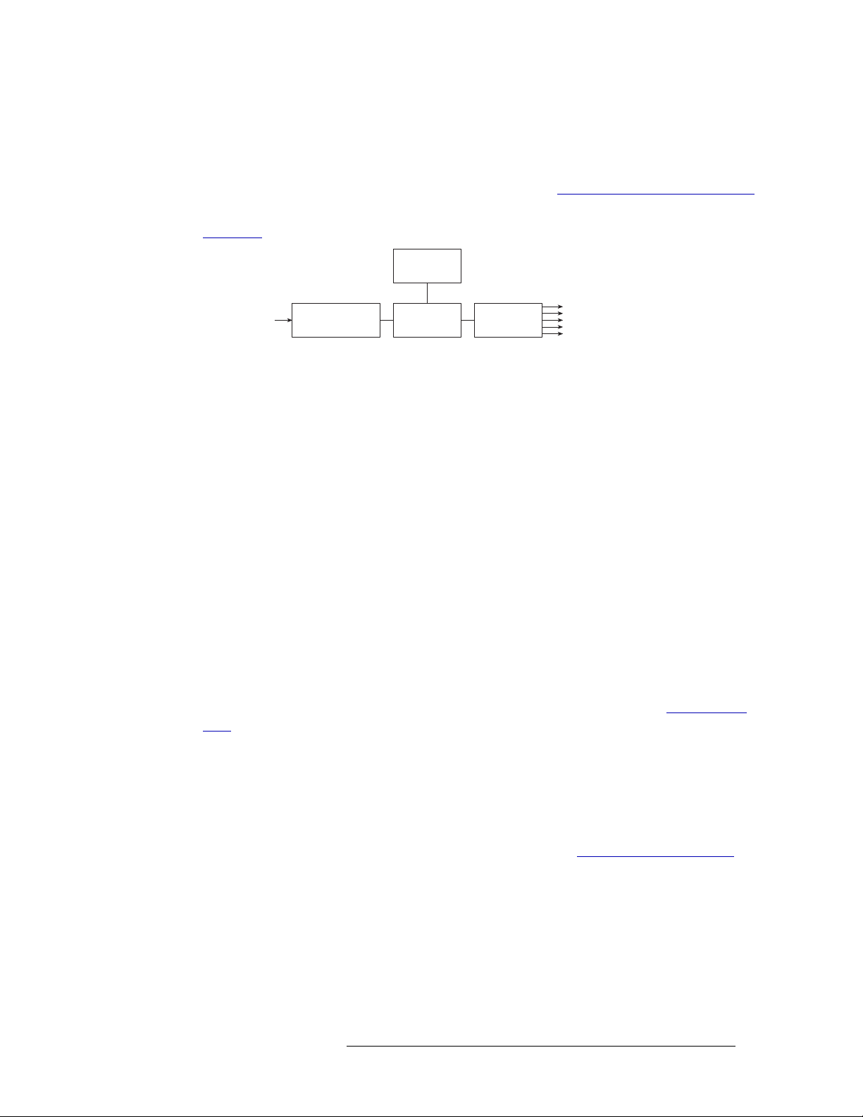
Figure 1-1
90130VAC or
180250VAC In
Figure 1-1. PS6000 Power Supply Module Diagram
shows the power supply architecture.
Power Sense
and Limiting
AC Input, Fuse,
Rectifiers, and Filter
Power Factor
Correction
+48VDC
Regulators (×5)
+48VDC
Out (×5)
Redundancy
The NV6257 can have a maximum of 8 AC power cords connected: up to four primary and four
optional for redundancy, creating a resilient power supply system. Each power cord connected corresponds to an installed PS6000 power supply module. Because there are multiple primary power
cords, if one becomes detached or fails, only power to the corresponding individual PS6000 module is interrupted. If the optional power cords are connected, there is no interruption in power
should a primary power cord fail.
Fuses
Fuses for AC power inputs are located on the PS6000 power supply modules. When a NV6257 is
ordered, fuses appropriate for the line voltage in use at the country of destination are installed on
the PS6000 power supply modules. Be sure to check the fuse ratings for compliance with specific
requirements in your area. A 7.5A fuse is required for 90-130
operation, a 3.75A fuse is required.
VAC applications. For 180-250 VA C
The fuses are “slow blow” and designed to blow if there is an ongoing power issue, but not if there
is a single, minor spike in the power flow. For information on replacing fuses, see Fuse Replace-
ment on page 100.
Cooling
There are four low-speed fans located along the front edge of each PS6000 power supply module.
Each fan pulls a small quantity of air across the internal heat sinks. In addition, the NV6257 has a
single fan that draws air through the power supply chassis. The frame fan is powered by PS6000
power supply modules installed in either slot PS1 or slot PS2 (see Making Power Connections
page 35).
NV7512 Audio Router • User’s Guide 3
on
Page 14

1. Introduction
Signal Types and Rates
Signal Types and Rates
The NV7512 supports AES, MADI and analog signals. Analog signals are converted to digital with
a sample rate of 48kHz for internal routing. Outgoing digital audio signals can be converted to analog for distribution. In addition, all stereo signals are separated into left and right channels for routing as mono signals. Mono channels can be recombined to create new stereo signals.
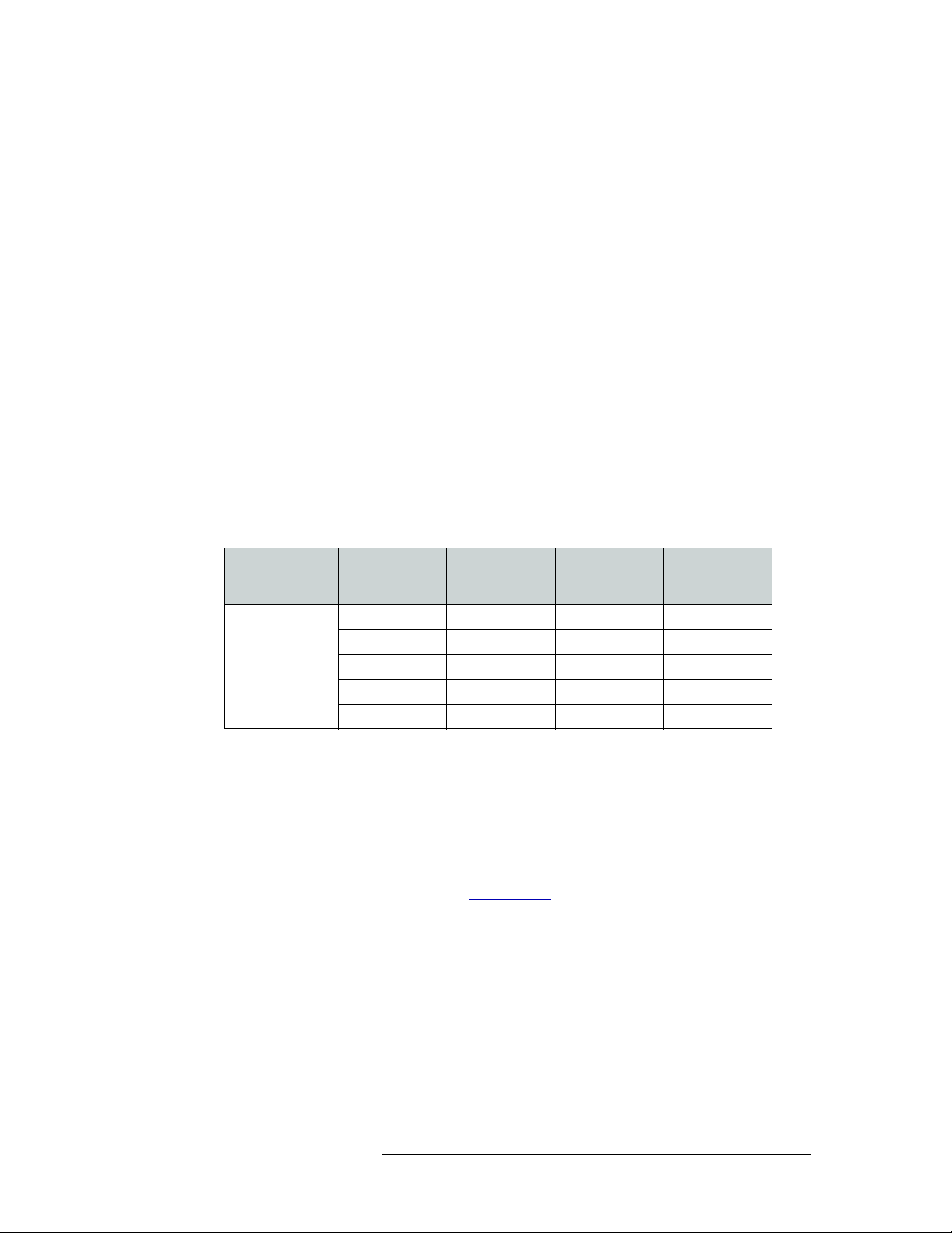
The following table lists the sample rates and how many signals at each rate an input card or output
card can support. Each signal type requires a specific input or output card. For a description of each
card and corresponding card part numbers, see Input Cards
page 26.
on page 20 and Output Cards on
Sample Rates
Signal Type
AES synchronous
(balanced and unbalanced)
MADI synchronous streams
(unbalanced)
Analog 48kHz; 25 bits 16 stereo sources
Supported
48
kHz
96kHz
192kHz
kHz
48
96kHz
One Input Card
Supports
32 stereo sources at 48kHz
16 stereo sources at 96kHz
8 stereo sources at 192kHz
2 streams totaling:
64 channels, 24 bits at
48kHz
32 channels, 24 bits at
96kHz
Note: One stream may
contain all 64 or 32
channels.
Converts analog to internal
digital format.
One Output Card
Supports
32 stereo destinations at
kHz, 96kHz or 192kHz
48
(any combination of rates)
2 streams;
2 optional AES reference
outputs, timed to the output
data sampling rate.
Note: Reference not used
for inputs because signals
converted to 48
internal routing.
16 stereo destinations
Converts internal digital
format to analog.
kHz for
For MADI signals, an optional MADI reference can be used for signals arriving at sample rates
other than 48kHz. (See MADI Reference
on page 67.) In addition, a Sample Rate Converter submodule can be installed to support asynchronous signals. (See MADI Asynchronous Sample Rate
Converter Sub-Module on page 23.)
Each signal requires a specific type of connector. Connectors are housed on backplanes installed on
the back plate. For a list of signals and corresponding connector types and backplanes, see Back-
planes on page 12.
Mixing AES Signal Sample Rates
The NV7512 can support three incoming sample rates for AES synchronous signals: 48 kHz,
96kHz or 192kHz. The rate of the signal determines how many signals are supported and through
which connectors the signal may be received.
The router receives a maximum of 32 stereo signals through coaxial connectors housed on I/O
backplanes. (See Backplanes
each. Each of the four sets can have a different sample rate totalling up to 192kHz for all four sets.
The faster the sample rate, the fewer the number of signals the input card can support. Similarly, the
sample rate determines how many and which connectors on the backplane are used to receive the
signals.
4 Rev 1.3 • 10 Oct 08
on page 12.) The 32 signals are divided into four sets of 8 signals
Page 15
1. Introduction
Signal Types and Rates
Output sample rates will be identical to the input sample rate. For example, if the input sample rate
is 96kHz, the output sample rate will be 96 kHz.
Because unbalanced and balanced signals use different I/O connectors, the connectors used to
receive and distribute signals differ depending on the signal type.
For AES unbalanced signals, the I/O backplane passes signals through 32 individually numbered
connectors, starting at 1 and continuing sequentially up to 32. The sample rate of the signal determines how many signals a single input card supports and which coaxial connectors are used, as follows:
• If the rate is 48kHz, all 32 connectors may be used.
• If the rate is 96kHz, every other connector may be used, starting at 1 and leaving the next disconnected (1, 3, 5, 7, etc.). A total of 16 inputs may be used.
• If the rate is 192kHz, every fourth input may be used, starting at 1 and leaving the next three
disconnected (1, 5, 9, 13, etc.). A total of 8 inputs may be used.
For AES balanced signals, the I/O backplane passes signals through four DB25 connectors numbered 1-8, 9-16, 17-24 and 25-32, respectively.
The following lists the different combinations for different incoming sample rates, and the related
connector numbers used on the I/O backplane:
Sample rate of
incoming signals
for each input.
“X” denotes input
connector not
used.
Input
1, 5, 9, 13, 17,
21, 25, 29
192 X X X
96 X 96 X
96 X 48 48
48 48 96 X
48 48 48 48
Input
2, 6, 10, 14, 18,
22, 26, 30
Input
3, 7, 11, 15, 19,
23, 27, 31
Input
4, 8, 12, 16, 20,
24, 28, 32
Sample rates between connected router frames can be 48kHz, 96kHz or 192 kHz.
Mixing Analog and Digital
The NV7512 frame can mix analog and digital audio signals within a single routing system. For
example, a digital input can be routed to an analog output. Using analog-to-digital and digital-toanalog convertors on the analog input cards and analog output cards, the router converts analog signals to digital or digital to analog. (See Active Cards
lower overall conversion costs when integrating existing analog devices into an existing plant.
on page 20.) This feature can dramatically
NV7512 Audio Router • User’s Guide 5
Page 16

1. Introduction
Signal Types and Rates
The following is a list of signal types and inter-mix options. In all cases, audio path delay does not
introduce any “lip sync” issues and can safely be ignored.
Input Type Output Type Mix Options Delay
Analog Analog Analog input
Analog Digital Analog input
Digital Analog AES synchronous input
Digital Digital AES synchronous input
< 1.2 mS
and
analog output
~658 µS
or
AES synchronous input
and
AES synchronous output
~539 µS
and
Analog output
104.2 µS
and
AES synchronous output
Mono Channels
The NV7512 routes AES signals internally as mono channels. The router can route individual channels independently or recombine channels to create new stereo signals. To perform switching, an
external AES reference signal must be connected to maintain synchronization.
AES signals are comprised of five parts: a preamble, left channel, channel status bits and right
channel. When received as a stereo signal, the signal is broken apart, separating out the left and
right channels to create two mono channels. The mono channels are then managed as separate signals within the router. The channel status bit and user bits are passed through. When the signal is
distributed as output, the preamble, channel status bit and user bits are added back to the left and
right channels to create a stereo signal.
When routed as a mono signal, individual left or right channels can be combined with other individual channels and distributed as a new channel-pair combination (stereo signal). For example, a
live news report may capture the news reporter’s voice on the left channel and the background
noises on the right channel. By splitting the AES signal into its left channel and right channel, the
news reporter’s voice (left channel) can be paired with a different background noise (right channel).
There must be two channels for the signal to be regenerated as a single stereo output.
How mono signals are recombined and routed to outputs is determined by the router control system.
6 Rev 1.3 • 10 Oct 08
Page 17

Switching Configurations
The NV7512 is designed to be highly flexible, allowing the creation of a wide variety of configurations for routing incoming and outgoing signals. A single router can route a maximum of 512
inputs and 512 outputs (AES synchronous stereo). By connecting two routers together, the number
of signals managed can be doubled to a maximum of 1,024 inputs and 1,024 outputs, increasing to
2,048 inputs and 2,048 outputs if the maximum of four routers are connected together (AES synchronous stereo). Depending on the signal type and the corresponding input card or output card,
each card supports a minimum of 8 signals (AES synchronous at 192kHz) up to a maximum of 32
signals (AES synchronous at 48kHz). Switching configurations can be created based on 8 up the
maximum number of inputs and outputs allowed: 512 inputs and 512 outputs (1,024 inputs and
1,024 outputs mono).
Crosspoint Card Slots and Outputs
A single NV7512 can have up to four crosspoint cards, 16 input cards, and 16 output cards
installed. Each input card sends incoming signal information to all other crosspoint cards. This
enables each crosspoint card to route any incoming signal from any input card. However, each crosspoint card manages a maximum of four output cards. In other words, a single crosspoint card can
support a maximum of 512 inputs x 128 outputs (AES synchronous). Because a router frame can
house up to 16 output cards, to manage all 16 output cards, four crosspoint cards must be installed.
1. Introduction
Switching Configurations
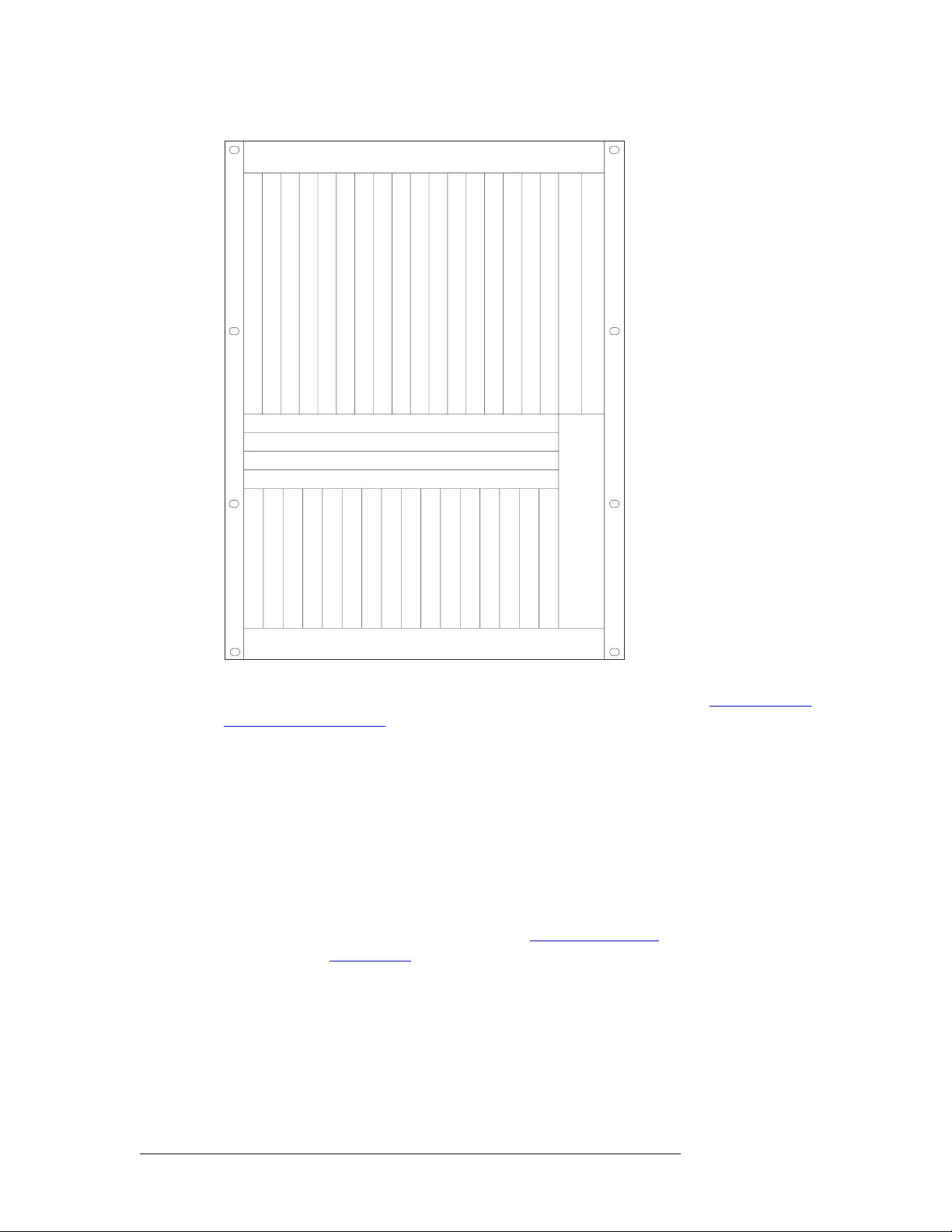
The router frame has four crosspoint card slots. (See Figure 1-2 on page 8.) The slot in which the
crosspoint card is installed determines which outputs are managed.
Figure 1-2 shows each crosspoint card slot. For clarity, the slots have been labeled A through D.
The crosspoint card installed in each slot manages signals as follows:
•Slot A
•Slot B
•Slot C
— Routes all inputs and local outputs 1–128. Card is installed in the top slot.
— Routes all inputs and local outputs 129–256. Card is installed in the center-top slot.
— Routes all inputs and local outputs 257–384. Card is installed in the center-bottom
slot.
•Slot D
— Routes all inputs and local outputs 385–512. Card is installed in the bottom slot.
Because each crosspoint card forwards signals to four output cards, only those crosspoint cards
routing outputs need to be installed. For example, if output cards for outputs 1–256 are installed,
then crosspoint cards only need to be installed in slots A and B; the C and D slots can remain
empty.
NV7512 Audio Router • User’s Guide 7
Page 18
1. Introduction
Switching Configurations
Outputs 132
Outputs 33-64
Outputs 65-96
Outputs 97-128
Outputs 129-160
Outputs 161-192
Outputs 193-224
Outputs 225-256
Slot A - Crosspoint (Outputs 1-128)
Slot B - Crosspoint (Outputs 129-256)
Slot C - Crosspoint (Outputs 257-384)
Slot D - Crosspoint (Outputs 385-512)
Fan
Outputs 257-288
Outputs 289-320
Outputs 321-352
Outputs 353-384
Outputs 385-416
Outputs 417-448
Outputs 449-480
Outputs 481-512
Monitor
Control Secondary
Control Primary
Fan
Inputs 132
Inputs 33-64
Inputs 65-96
Inputs 97-128
Inputs 129-160
Inputs 161-192
Inputs 193-224
Inputs 225-256
Inputs 257-288
Inputs 289-320
Inputs 321-352
Inputs 353-384
Inputs 385-416
Inputs 417-448
Inputs 449-480
Inputs 481-512
Fan
Figure 1-2. Crosspoint Card Slot Locations (Front View)
For more information on inputs and outputs and assigned signal numbers, see Slots and Corre-
sponding Signal Numbers on page 10.
Minimum Number of Crosspoint Cards and Output Cards
Because each crosspoint card manages four output cards, the number of crosspoint cards installed,
and where installed, is determined by the number and location of output cards installed. Crosspoint
cards send input information to all other crosspoint cards, so where input cards are installed is not a
factor. Output cards manage outgoing signals. Only the number of cards required to support the signals being distributed need to be installed.
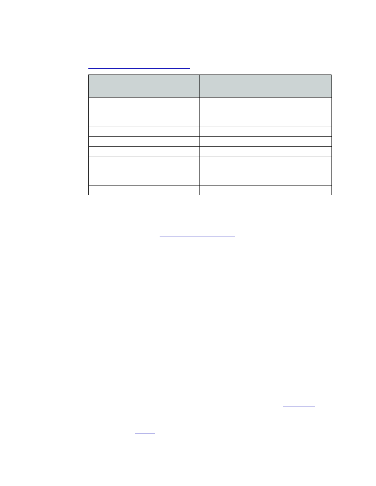
The following table lists possible crosspoint card installation configurations when the NV7512 is
used as a standalone router. The table lists in which slot crosspoint cards and output cards are
installed and the minimum number required (see Figure 1-2 on page 8
type of card, see Active Cards
on page 20. This list is not exhaustive, but shows a sampling of the
wide variety of configurations that can be created. Although the examples list a full complement of
input cards (512 stereo inputs) and output cards for managing the maximum number of signals
listed (32 outputs per card), only the specific number of cards required for the number of inputs
). For a description of each
8 Rev 1.3 • 10 Oct 08
Page 19
1. Introduction
Module Slots and Rear Connectors
being supported need to be installed. For more information on input and output signal numbers, see
Slots and Corresponding Signal Numbers
on page 10.
Tot al Number
Total Number o f
Inputs x Outputs
512 × 512 1–512 16 4 A, B, C, D
512 × 384 1–384 12 3 A, B, C
512 × 384 129–512 12 3 B, C, D
512 × 384 1–128, 257–512 12 3 A, C, D
512 × 256 1–256 8 2 A, B
512 × 256 129–384 8 2 B, C
512 × 256 257–512 8 2 C, D
512 × 256 1–128, 257–384 8 2 A, C
512 × 128 129–256 4 1 B
512 × 128 385–512 4 1 D
Output Signal
Numbers
of Output
Cards
Total Numbe r
of Crosspoint
Cards
Crosspoint Card
Slot
Connecting Multiple Routers
Each router can have up to four crosspoint cards installed. When two or more routers are connected
together, the crosspoint cards can route all local inputs plus all inputs received through the signal
expansion connections. (See Signal Expansion Connections
nected together, each with 512 inputs, the combined signals routed by the router is 1024 inputs. Up
to four NV7512 routers can be connected together to route a maximum of 2048 inputs and 2048
outputs (AES synchronous stereo). For more information, see Frame Expansion
on page 53.) If two routers are con-
on page 29.
Module Slots and Rear Connectors
The NV7512 has slots for input, output, crosspoint, control and monitor cards. Cards are installed
in slots readily accessed through the front of the router frame. The rear of the router is a back plate
into which backplanes housing coaxial connections for receiving and distributing signals are
installed. The back plate also contains connections to system functions, such as a router control system, alarms or references.
Front Slots
Figure 1-3 on page 10 shows the front of the NV7512 with the door removed. From this view, the
16 upper bay slots for output cards and 16 lower bay slots for input cards are visible. In the center
of the router are four horizontal slots for crosspoint cards. In the right-hand section of the upper bay
are two more slots for the primary and secondary (optional for redundancy) control cards. A slot for
the monitor card is also located in the right-hand section of the upper bay, between the output card
slots and the control card slots. For more information on each type of card, see Active Cards
page 20.
A fan tray is located at the top, bottom, and right side of the router chassis. For more information on
frame cooling, see Cooling
NV7512 Audio Router • User’s Guide 9
on page 2.
on
Page 20
1. Introduction
Module Slots and Rear Connectors
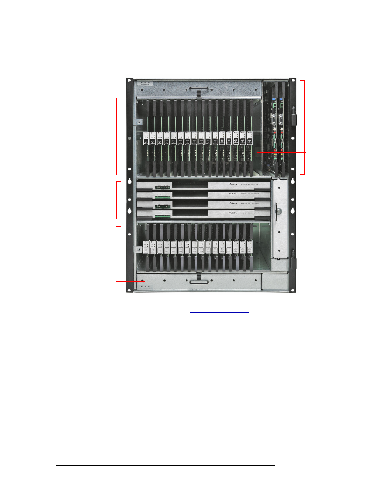
Figure 1-3 shows where different cards and the fan trays are located in the frame, as viewed from
the front. The monitor card is optional and not shown as installed.
Fan Tray
Output
Cards
(16)
Crosspoint
Cards
(4)
Input
Cards
(16)
Fan Tray
Figure 1-3. NV7512 Router with Cards Installed, Door Removed (Front View)
Control
Cards
(2)
Monitor
Card
Fan Tray
For information on installing cards, see Installing Active Cards on page 42.
Slots and Corresponding Signal Numbers
The router has 16 slots for input cards and 16 slots for output cards. Slots are numbered 1, 2, and so
on, from left to right, when facing the front of the router. Each input card slot and output card slot,
and the card it holds, receives or distributes signals through coaxial connectors housed on a backplane. Each signal is assigned a number that corresponds to the physical input or output connection
up to the maximum number of signals allowed (32). The signal numbers correspond to the slot in
which an input card or output card is installed: Input slot 1 corresponds to inputs 1–32, input slot 2
corresponds to inputs 33-64, and so on, up to 512, as shown in Figure 1-4 on page 11. Output slots
are similarly numbered, such that output slot 1 corresponds to outputs 1–32, output slot 2 corresponds to outputs 33–64, and so on, up to 512, as shown in Figure 1-4 on page 11.
10 Rev 1.3 • 10 Oct 08
Page 21
Outputs 132
Outputs 33-64
Outputs 65-96
Outputs 97-128
Outputs 129-160
Outputs 161-192
Outputs 193-224
Outputs 225-256
Slot A - Crosspoint (Outputs 1-128)
Slot B - Crosspoint (Outputs 129-256)
Slot C - Crosspoint (Outputs 257-384)
Slot D - Crosspoint (Outputs 385-512)
Fan
Outputs 257-288
Outputs 289-320
Outputs 321-352
Outputs 353-384
Outputs 385-416
Outputs 417-448
Outputs 449-480
Outputs 481-512
Monitor
Module Slots and Rear Connectors
Control Secondary
Control Primary
Fan
1. Introduction
Inputs 132
Inputs 33-64
Inputs 65-96
Inputs 97-128
Inputs 129-160
Inputs 161-192
Inputs 193-224
Inputs 225-256
Inputs 257-288
Inputs 289-320
Inputs 321-352
Inputs 353-384
Inputs 385-416
Inputs 417-448
Inputs 449-480
Inputs 481-512
Fan
Figure 1-4. Inputs and Outputs, Numbers Assigned (Front View)
Analog Signals and Signal Numbers
The router frame slots have printed labels that list signal numbers corresponding to AES synchronous stereo signals, numbers 1 through 32. This numbering scheme does not correspond to analog
signals.
For AES stereo signals, 32 signals can be supported, matching the labeling for signal numbers on
the router frame. For analog signals, only 16 analog stereo signals are supported, so signals do not
match the 32 signal number labels. The stereo signal is received through input 1, then input 3, then
input 5, and so on, up to 32, skipping every other signal label number in sequence. However, 32
mono signals can be received, matching the router label number scheme.
When routing mono and analog signals, it is recommended that a labeling convention be adopted
and rigorously followed for all mono switching configurations.
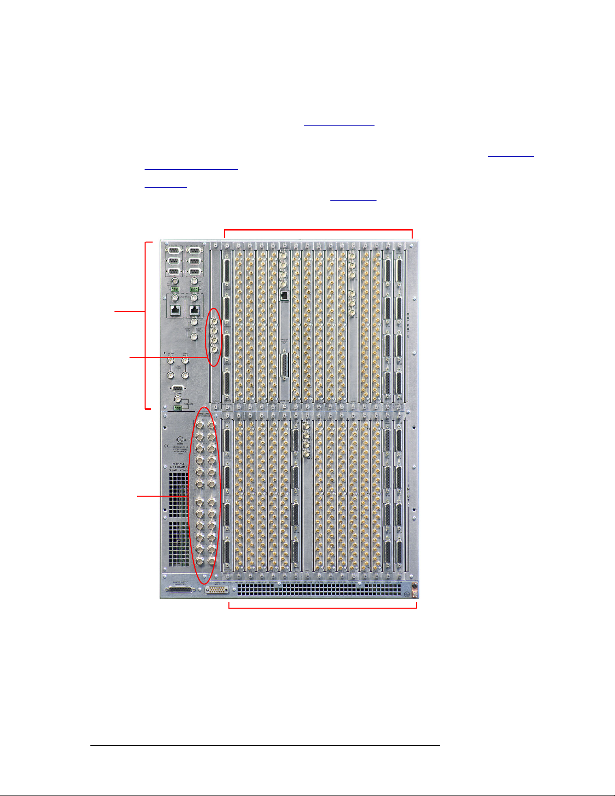
Rear Connections
The rear of the NV7512 (Figure 1-5 on page 12) features a back plate containing backplanes for
receiving and distributing signals. Each backplane contains passive connectors that pass the signals
through to active, receiving connections on the input cards and output cards.
An additional backplane, located in the left-hand section of the upper bay, contains four BNC connectors for the monitor card. In the left-hand region and lower, left-hand corner of the frame are
NV7512 Audio Router • User’s Guide 11
Page 22
1. Introduction
Module Slots and Rear Connectors
connections for system and power functions, as shown in Figure 1-7 on page 15. In the lower
region of the frame, near the left-hand side, are expansion connections used to send signals between
connected NV7512 router frames. (See Frame Expansion
Each of the four crosspoint card slots manage up to 128 outputs, or four output cards managing up
to 32 outputs each. For information on crosspoint cards and the signals managed, see Crosspoint
Card Slots and Outputs on page 7.
on page 29.)
System
Connectors
(see
expanded
figure)
Monitor
Connectors
(4)
Figure 1-5
nectors located on the inner motherboard (see Backplanes
shows the rear of the router frame with backplanes installed. Backplanes plug into con-
on page 12). Active cards, shown in
Figure 1-3 on page 10, plug into the same motherboard from the front.
Output Connectors - Backplanes (16)
Expansion
Connectors
(24)
Input Connectors - Backplanes (16)
Figure 1-5. NV7512 Router with MADI and AES Backplanes (Rear View)
Backplanes
The NV7512 features rear backplanes that can be inter-mixed in a single router frame. (See
Figure 1-5.) Each backplane contains connectors for receiving or distributing signals. The number
of connectors on a backplane and the type of connector is determined by the signal type.
12 Rev 1.3 • 10 Oct 08
Page 23
1. Introduction
Module Slots and Rear Connectors
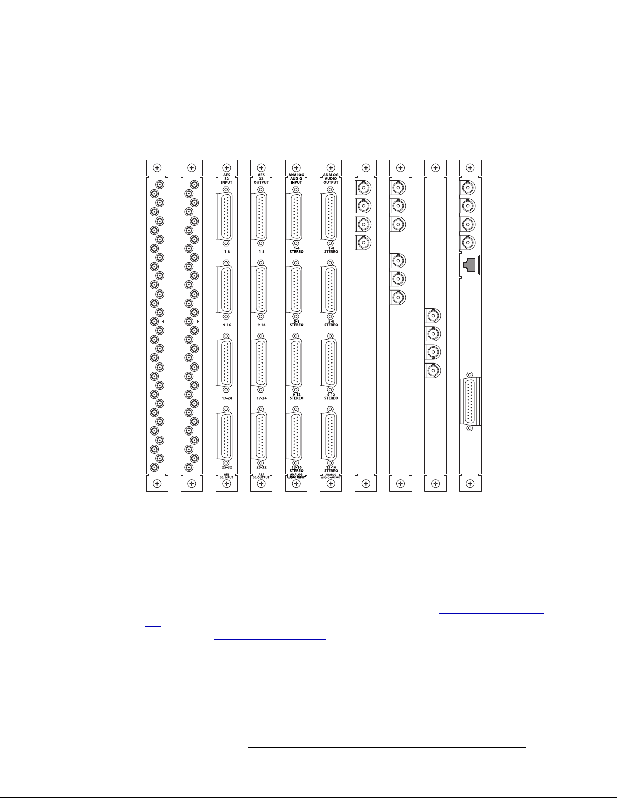
There are five types of backplanes, each featuring a unique set of connectors, as shown in Figure 1-
6. The type of signal being received or distributed determines the backplane used. For each backplane installed a corresponding input card or output card must also be installed. For example, if a
backplane is installed to receive AES unbalanced signals, then the input card for AES unbalanced
signals must be installed in the corresponding card slot. (See Input Cards
on page 20.)
32 INPUT
2
4
6
8
10
12
14
16
18
20
22
24
26
28
30
32
32 INPUT
AES
AES
AES
32 OUTPUT
1
3
5
7
9
11
13
15
17
19
21
23
25
27
29
31
2
4
6
8
10
12
14
16
18
20
22
24
26
28
30
32
AES
32 OUTPUT
1
3
5
7
9
11
13
15
17
19
21
23
25
27
29
31
MADI
INPUT
MADI
INPUT
MADI
OUTPUT
IN 1
REF 1 OUT
REF 1
REF 1 IN
IN 2
REF 2
REF 2 OUT
REF 2 IN
MADI
OUTPUT
OUT 1
OUT 2
OUTPUT
MONITOR
OUTPUT
MONITOR
QUAD MIX
OUTPUT
1
2
3
4
10/100BT
1
2
ANALOG
AUDIO
OUT
3
4
QUAD MIX
OUTPUT
AES Coax
(Unbalanced)
AES DB25
(Unbalanced)
Analog Audio
(DB25)
MADI
(BNC)
Output
Monitor
Quad
Mix
Figure 1-6. NV7512 Backplanes
Backplane connectors are labeled with numbers that correspond to the number assigned the signal
passing through the connector. Signal numbers are used when creating switching configurations
(see Switching Configurations
on page 7). For example, on the ‘AES Unbalanced’ backplane, each
connector is labeled ‘1’, ‘2’ and so on up to ‘32’. The signal passing through connector ‘1’ is routed
as signal number 1, the signal passing through connector ‘2’ is routed as signal number 2, and so
on. For a list of all backplane types, connectors and signals managed, see Backplane Types and Sig-
nals on page 14. For information on making connections between backplanes and signal sources or
destinations, see Making Signal Connections
on page 44.
Quad Mix Backplane
Unlike other backplanes, the Quad Mix backplane features three different types of connectors on a
single backplane. Four BNC connectors distribute up to four AES unbalanced audio outputs. A single DB25 connection can distribute up to 8 stereo or 16 mono analog audio outputs. An additional
Ethernet connection provides a connection to the Quad Mix control panel (NV9660). The NV9660
NV7512 Audio Router • User’s Guide 13
Page 24

1. Introduction
Module Slots and Rear Connectors
manages the signal mixing performed by the Quad Mix card and is required if the Quad Mix backplane and Quad Mix output card are installed. For more information about the Quad Mix card, see
Quad Mix
tion on connecting to the NV9660, see NVISION’s NV9660 Quad Mix Control Panel
Monitor Backplane
The monitor backplane features four BNC connectors that distribute outgoing signals for monitoring purposes. Each BNC connector can be connected to external monitoring equipment so that the
quality of outgoing signals can be verified. The monitor backplane has a corresponding monitor
card and is installed in a unique backplane slot in the back plate. There is no corresponding input
backplane or input card. For more information, see Installing Backplanes
Card on page 29.
Backplane Types and Signals
The following is a list of each backplane type, associated connectors, signal types managed, and the
number of signals each backplane can receive or distribute. For your convenience, the part number
for each backplane is included.
on page 28. There is no corresponding input backplane or input card. For more informa-
on page 98.
on page 41 and Monitor
Connectors
Type of Signals
Managed
AES unbalanced,
synchronous
AES balanced,
synchronous
Analog Analog DB25 4 16 stereo
MADI unbalanced,
synchronous
Note: 2 connectors
support 2 signal
streams; 2
connectors support
optional MADI
references (see
Backplane
Name
AES DIN 1.0/2.3 32 32 stereo
AES DB25 4 16 stereo
MADI BNC 4 64 mono EM0492 EM0493
Connector
Typ e (s)
per
Backplane
Signals
Managed
64 mono
32 mono
32 mono
MADI Reference
on page 67).
AES unbalanced and
Analog
(Ethernet connection
to Quad Mix control
panel, NV9660)
Forwards outgoing
signals to monitor
equipment (see
Quad Mix
(output only)
Monitor BNC 4 1 output from
BNC
Ethernet
DB25
4 BNC
1 Ethernet
1 DB25
AES
balanced:
4 stereo
Analog:
4 stereo or
8 mono
each output
card
Monitor Card on
page 29).
Part
Number
(Input)
EM0486 EM0485
EM0490 EM0491
EM0420 EM0421
N/A EM0512
N/A EM0429
Part
Number
(Output)
14 Rev 1.3 • 10 Oct 08
Page 25
1. Introduction
Module Slots and Rear Connectors
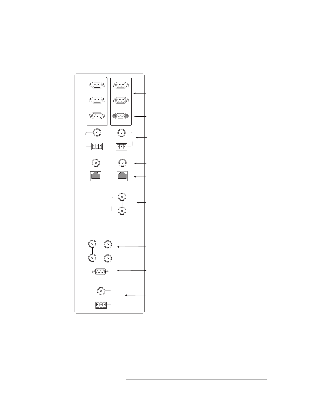
System Connections
The NV7512 features connections for managing system functions. These connections are used to
connect to:
•A router control system using either
serial, Ethernet or GSC Node Bus connectors.
•A stable source of audio signal for reference purposes.
•The UniConfig application, installed
on a configuration PC.
•A system alarm that sends notification
of a system failure, such as a fan malfunction.
AES
REF1
PRI CTRL
CTRL 1
CTRL 2
DIAG
SEC CTRL
CTRL 1
CTRL 2
DIAG
AES
REF2
Serial Connections
to Control System
Diagnostic
Connections
AES
Reference
PRI CTRL
10 B 2
10/100 B T
VIDEO
REF 1
LOOP
THRU
ALARMS
VIDEO
(2)
SEC CTRL
10/100 B T
NODE
BUS
REF 2
TIME CODE
10 B 2
LOOP
THRU
Expansion
Connections for
Control System
Ethernet
Connections
to Control
System
GSC Node Bus
Connection
to Control System
Video Ref
Connections
System Alarm
Connection
Time Code
Reference
(Not supported
at this time)
•A power supply alarm that sends notification of a power supply failure.
Figure 1-7 shows the system connections
located on the rear of the router. Time
Code references are not supported at this
time.
Each system connection and function is
described in the proceeding sections.
Figure 1-7. System Connections for the NV7512 (Rear View)
NV7512 Audio Router • User’s Guide 15
Page 26
1. Introduction
Module Slots and Rear Connectors
Router Control System Connections
A router control system is used to manage routing configurations in the router. The router control
system sends instructions to the router control card, which in turn sends commands directing signal
switching in the router. A router control system is a separate external unit, which is connected to the
router. The NV7512 provides three types of a router control system connections: serial, Ethernet or
GSC Node Bus. The router control system determines which connection is used. For example, to
connect to the NVISION NV9000 router control system an Ethernet connection is preferred.
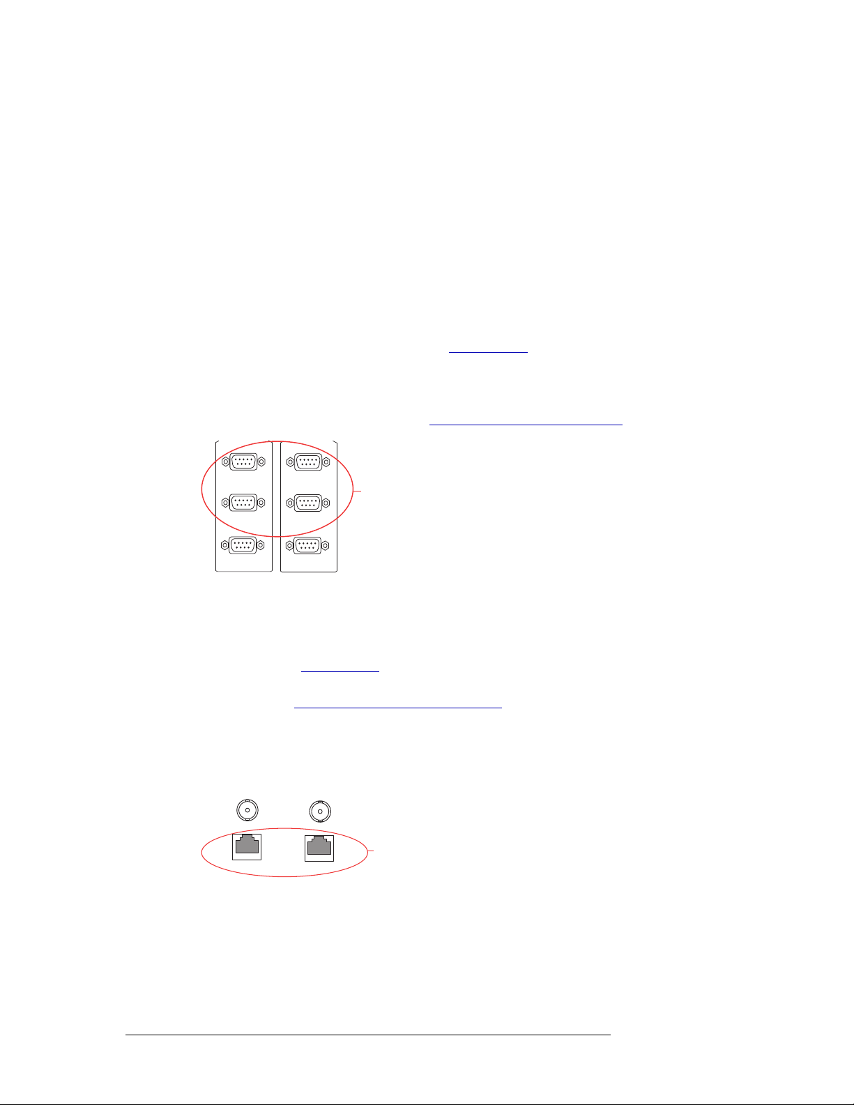
Serial Connections
The NV7512 has four serial router control system connections, as shown in Figure 1-8. The connections are divided into two sets, one primary (‘PRI CTRL’) and one secondary (‘SEC CTRL’).
Primary control connects to the primary control card. Secondary control connects to the secondary
(optional for redundancy) control card. (See Control Cards
into connections that correspond to router control systems: ‘CTRL 1’ corresponds to the primary
control system and ‘CTRL 2’ corresponds to a redundant control system. Using ‘CTRL 2’ connections, you can connect to an alternate control system (i.e., backup system) or set up dual control, if
desired. For installation instructions, see Serial Router Control Connections
PRI CTRL
on page 20.) Each set is further divided
on page 58.
SEC CTRL
CTRL 1
CTRL 2
DIAG
Figure 1-8. Serial Connections to Router Control System (Rear View)
CTRL 1
CTRL 2
DIAG
Serial Connections
to Control System
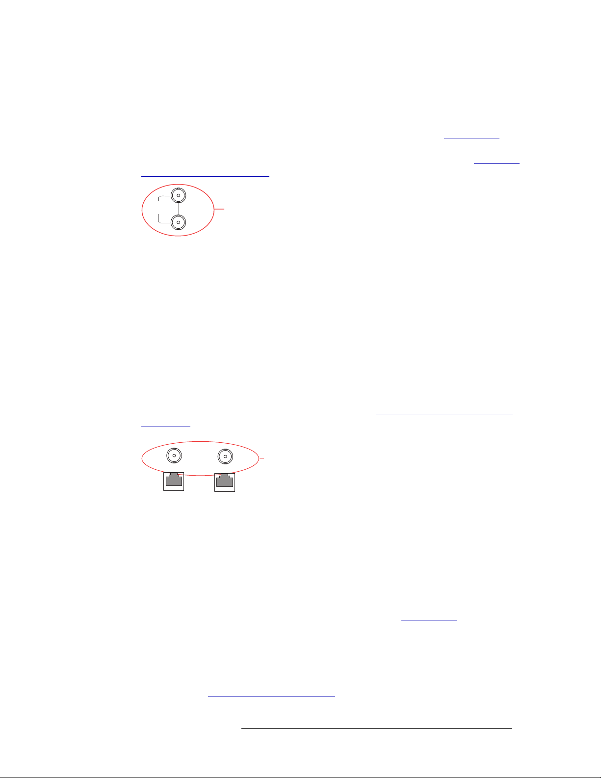
Ethernet Connections
The NV7512 has two Ethernet router control system connections, labeled ‘10/100 BASET’, as
shown in Figure 1-9. Both connections are shared by the primary control card and the secondary
control card. (See Control Cards
on page 20.) Because Ethernet network connections can be used to
connect to alternate control systems, there are no separate connections provided. For installation
instructions, see Ethernet Router Control Connections
on page 59.
In order for the router to communicate with the router control system through an Ethernet connection, an IP address for the router needs to be set in the control card. The IP address is set using UniConfig. For more information, see the UniConfig User’s Guide.
COMMON
TO
PRI & SEC
10 BASE 2
10/100 BASE T
Figure 1-9. Ethernet Connections to Router Control System (Rear View)
10 BASE 2
10/100 BASE T
Ethernet
Connections
to Control
System
16 Rev 1.3 • 10 Oct 08
Page 27
1. Introduction
Module Slots and Rear Connectors
GSC Node Bus Connections
Some third-party router control systems require a GSC Node Bus connection. The NV7512 has one
GSC Node Bus connection, labeled ‘NODE BUS’, as shown in Figure 1-10. The connection is
shared by both the primary control card and the secondary control card. (See Control Cards
page 20.) To use the GSC Node Bus connection, an optional module must be installed on each control card being used. For details, contact NVISION. For installation instructions, see GSC Node
Bus Router Control Connections on page 60.
on
NODE
BUS
Figure 1-10. GSC Node Bus Connections to Router Control System (Rear View)
LOOP
THRU
GSC Node Bus
Connection
to Control System
Router Control System Expansion Connections
In order to manage multiple connected NV7512 routers, the router control system expansion connections need to be connected between the routers. Control system expansion connections are
located on the rear of the router, labeled ‘10 BASE 2’, as shown in Figure 1-11.
When making router control system connections, only one router is directly connected to the router
control system. This router acts as the primary router. When connecting two or more routers, each
router’s control system expansion connection is connected to the next router in line, ending with the
primary router. For example, if connecting four routers, Router 4 is connected to Router 3, which is
connected to Router 2, and Router 2 is connected to Router 1. Router 1 is the primary router and
connected directly to the router control system. This enables the router control system to communicate with all connected routers through the primary router’s control system connection. For instructions on making control system expansion connections, see Router Control System Expansion
Connections on page 61.
COMMON
TO
10 BASE 2
PRI & SEC
10 BASE 2
Expansion
Connections for
Control System
10/100 BASE T
Figure 1-11. Expansion Control System Connections (Rear View)
10/100 BASE T
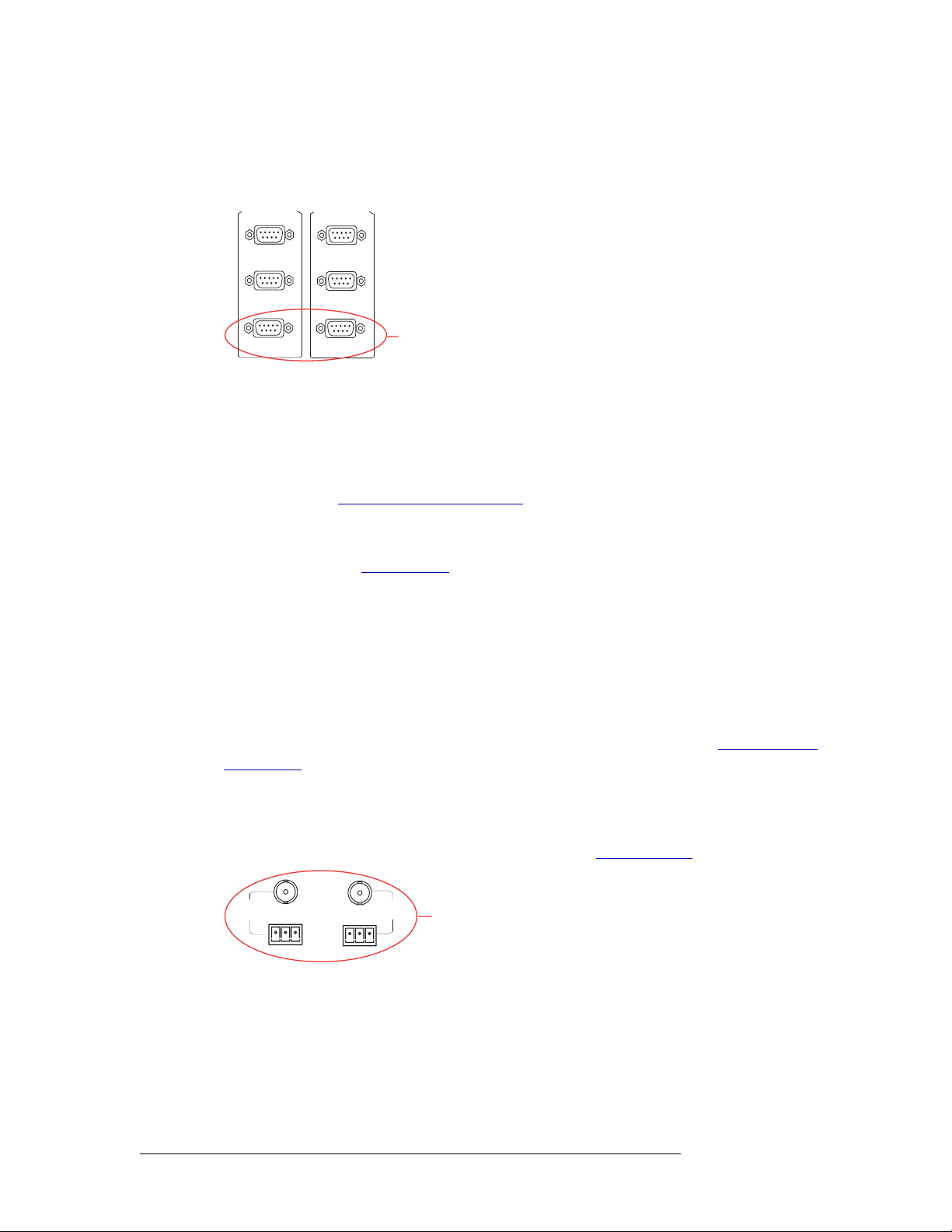
Diagnostic Connections
The diagnostic connections enable the NV7512 to communicate with the UniConfig application.
UniConfig runs on external hardware (e.g., PC) separate from the router and is used to perform system setup tasks, and configure and monitor the router. For more information on UniConfig, see the
UniConfig User’s Guide.
There are two types of diagnostic connections: temporary and permanent. A temporary diagnostic
serial connection is located on the front of each control card. (See Control Cards
manent diagnostic connections are located on the rear of the router, labeled ‘DIAG’, as shown in
Figure 1-12 on page 18. NVISION recommends using the temporary diagnostic connection when
configuring the router because the port has fixed communications parameters. The permanent diagnostic connections are used for upgrading firmware or control card protocols when there is no
Ethernet connection to the router. For instructions on making temporary or permanent diagnostic
connections, see Making Diagnostic Connections
NV7512 Audio Router • User’s Guide 17
on page 64.
on page 20.) Per-
Page 28
1. Introduction
Module Slots and Rear Connectors
There are two permanent ‘DIAG’ ports, one primary (‘PRI CTRL’) and one secondary (‘SEC
CTRL’). The primary control connects to the primary control card. The secondary control connects
to the secondary (optional for redundancy) control card.
PRI CTRL
SEC CTRL
CTRL 1
CTRL 2
DIAG
Figure 1-12. Permanent Diagnostic Connections (Rear View)
CTRL 1
CTRL 2
DIAG
Diagnostic
Connections
AES Reference Connections
The AES reference is used for clock generation. The clock provides a timing reference for AES
synchronous signals and for the control card’s timing circuits. For optimum audio output, signals
must be clock-locked to the same reference. Input impedance is selected by setting jumpers on the
control card. (See Control Card Jumper Settings
The NV7512 has two AES reference connections labeled ‘AES REF1’ and ‘AES REF2’, as shown
in Figure 1-13 on page 18. Both connections are shared by the primary control card and the secondary control card. (See Control Cards
on page 20.) The AES reference connections are “redundant”
and use the same reference type. When both reference connections are connected, if one reference
fails, the control card automatically fails-over to the redundant reference.
Synchronous AES input cards can work with inputs that are not locked to a common AES reference. These inputs are treated as non-synchronous AES signals. Although possible, it is not recommended that you operate under these settings for high-quality program audio feeds. Router
specifications are not guaranteed; the audible effects may be unpredictable, depending on the program content and the degree of offset in the incoming data rate.
on page 85.)
An AES reference is required when using synchronous AES output cards. (See AES Reference
Connections on page 18.) While it is possible to let the clock generator on the control card free-run,
the synchronous AES outputs may contain ticks and pops, the severity of which depends on the difference in clock rate.
The AES reference connection requires a stable signal source of AES with a sample rate of 48kHz.
For instructions on making AES reference connections, see AES Reference
AES
REF1
Figure 1-13. Connections to AES References (Rear View)
AES
REF 2
AES
Reference
on page 67.
Video Reference Connections
The NV7512 provides timing reference connections for video signals, labeled ‘VIDEO REF 1’ and
‘VIDEO REF 2’, as shown in Figure 1-14. These connections provide a reference input for determining the router’s video frame switch point. The same reference can be used for both connections
or a different reference used for each connection.
18 Rev 1.3 • 10 Oct 08
Page 29

1. Introduction
Module Slots and Rear Connectors
If a video reference is present, signals switch at the defined frame and line switch points. If a video
reference is not present, the router still switches the signal, but to an internal reference. When the
video reference is not connected the control card red LEDs remain lit. (See Indicator LEDs
page 100.)
The video reference connections require a stable source of PAL, NTSC or Tri-level sync. For
instructions on making video reference connections, see Video Reference
on page 69.
Redundant and Dual References
There are two video reference connections. The same reference can be used for both connections or
a different reference for each connection. When using the same, or “redundant,” references for both
connections, if one reference fails, the control card automatically fails-over to the redundant reference. When using different references, or “dual” references, routing switch takes can be configured
to occur based on one or the other reference. For example, ‘VIDEO REF 1’ uses NTSC as a reference and ‘VIDEO REF 2’ uses PAL as a reference.
“Redundant” or “dual” mode is selected using UniConfig. If “dual” is selected, each output can be
configured individually to use ‘VIDEO REF 1’ or ‘VIDEO REF 2’ as the reference (see the UniConfig User’s Guide).
on
VIDEO
REF 1
Figure 1-14. Connections to Video References (Rear View)
LOOP
THRU
VIDEO
REF 2
Video Ref
Connections
Alarm Connections
The NV7512 provides system alarms that notify you of a malfunction, such as when a fan or power
supply is not functioning properly. The NV6257 (power supply) and the NV7512 each have alarm
connections that can be connected to external equipment that display visual signals when an alarm
is activated. Creation of external monitoring equipment is outside the scope of this manual. However, basic instructions on wiring the alarm connections for external monitoring is provided. See
Alarm Indicator Equipment
In addition to an alarm connection, the router control system receives status information from the
router’s control card(s). The control cards read the status of NV6257’s power supply and fans
through the ‘Power Supply Monitors’ connection. (See Module Slots and Rear Connectors
page 9.) At the same time, the control card monitors the local router’s power supply, fans, and
video reference connections. Both NV6257 and router information is then communicated to the
router control system and is viewable using UniConfig (see the UniConfig User’s Guide).
on page 72.
on
A SNMP agent can be installed on the router control system (i.e., NVISION 9000) to communicate
power supply information to a SNMP manager. Installation of SNMP agents and use of SNMP
managers is outside the scope of this User’s Guide.
NV7512 Audio Router • User’s Guide 19
Page 30

1. Introduction
Active Cards
The router alarm connection is labeled ‘ALARM’, as shown in Figure 1-15. For instructions on
making alarm connections, see Making Alarm Connections
Figure 1-15. Alarms Connection (Rear View)
Active Cards
The NV7512 features several active cards that manage incoming signals, forward commands from
the router control system, perform signal switching, and distribute outgoing signals. Each card
slides into a card guide and has a two levers that aid card ejection.
There are:
• 2 control cards (one primary, one secondary - optional for redundancy)
• Up to 16 input cards
• Up to 16 output cards
• Up to 4 crosspoint cards
• 1 monitor card (optional)
Each card and function is described in the proceeding sections. For information on installing cards,
see Installing Active Cards
ALARMS
System Alarm
Connection
on page 71.
on page 42.
Control Cards
The router has two control cards (EM0374), one primary and one secondary (optional for redundancy). A control card receives commands from the router control system, and in turn, controls the
input, output, crosspoint and monitor cards.
Both the primary control card and the secondary control card receive router control system commands, but only the primary control card actively sends commands to the crosspoint cards. Because
both cards receive router control system commands, if the active (primary) control card fails, the
back-up (secondary) control card automatically and seamlessly takes over processing. In addition,
the primary control card and secondary control card communicate with each other. Should either
control card fail, the now active control card communicates the failure to the router control system.
The control card also monitors taxometers on the fans, which indicate if the fan is spinning or not.
The control card forwards this information to the router control system for monitoring.
The control card includes a status reporting circuit. Four LEDs on the front of the control card indicate the card’s status: low battery (Red), alarm (Red), active (Amber) and operating normally
(Green). For more information, see Indicator LEDs
on page 100.
Input Cards
The router frame can house up to 16 input cards, each processing up to 32 signals, depending on the
card. Input cards receive incoming signals through passive coaxial connectors on backplanes. (See
Backplanes
on page 12.) There are three types of input cards managing different signal formats.
20 Rev 1.3 • 10 Oct 08
Page 31

1. Introduction
Active Cards
Different input cards can be inter-mixed in a single frame to meet specific switching configuration
needs.
Analog and AES synchronous signals may be converted between analog and digital within the
same router frame. (See Mixing Analog and Digital
nals may be routed as stereo or mono signals, but not as AES asynchronous channels.
The following is a list of the different input cards available. Each card is listed by the type of signal
it manages. For your convenience, the part number for each card has been included.
on page 5.) Analog or AES synchronous sig-
Number of
Input Card
AES synchronous
balanced and
unbalanced
MADI
synchronous
unbalanced
Analog 16 stereo
Inputs
32 stereo
64 mono
64 mono 2 streams totaling:
32 mono
Number of Incoming Signals
per Sample Rate
32 stereo (64 mono) at 48
16 stereo (32 mono) at 96kHz
8 stereo (16 mono) at 192kHz
64-channel, 24-bits at 48
32-channel, 24-bits at 96kHz
Note: One stream may contain all 64
or 32 channels.
16 stereo (rate N/A)
32 analog (rate N/A)
Converts analog input to internal
digital format at 48
kHz
kHz
kHz
Part Number
EM0488
EM0476
EM0418
For MADI signals, an optional MADI reference can be used for signals arriving at sample rates
other than 48kHz. (See MADI Reference
on page 67.) In addition, a pair of Sample Rate Converter
sub-modules can installed to support asynchronous signals. (See AES Synchronous (Balanced and
Unbalanced) on page 27.)
The functions of each type of card are described in the proceeding sections. Cards are listed by signal type supported.
AES Synchronous (Balanced and Unbalanced)
The AES synchronous input card (EM0488) receives balanced or unbalanced incoming signals
through local I/O connectors: DIN 1.0/2.3 for unbalanced signals and DB25 for balanced signals.
The input card receives up to 32 stereo signals. Each signal is transformer coupled. The signal is
then forwarded to a receiver. The receiver automatically determines if the incoming signal sample
rate (48kHz, 96kHz or 192 kHz) is valid for the signal input connectors being used. (See Mixing
AES Signal Sample Rates on page 4.)
Next, the receiver separates the signal into a right channel and a left channel, channel status information, and user bits. At that time, the sample rate of the signal is known (48kHz, 96 kHz or
192kHz) and sample rate information forwarded with the signal. The signal is synchronized to the
system clock; adding and dropping samples as needed until the signal is synchronized.
NV7512 Audio Router • User’s Guide 21
Page 32

1. Introduction
Active Cards
The receiver forwards the signal to a buffer, which in turns sends the signal to the motherboard and
onward to all crosspoint cards.
Note Near-synchronous operation may cause minor disturbances in the audio signal.
Figure 1-16 shows the signal flow for an AES synchronous input card.
These effects are usually masked by the program audio, depending on the sample
rate offset or magnitude and timing of the disturbance.
Input Card
Local Input
Connectors
(up to 32)
Figure 1-16. AES Synchronous Input Card Block Diagram
Transformer
Coupled
Receiver
All
Crosspoints
MADI (Unbalanced)
The MADI input card (EM0476) supports incoming MADI unbalanced signals received through
local BNC coaxial connectors. MADI audio signals are grouped into 32-bit packets for each audio
channel with one MADI frame composed of up to 64 continuous channels. MADI signals require a
reference in accordance with AES11 standards. (See MADI Reference
Using DIP switches on the input card, channels can be allocated between the two BNC connectors.
In addition, the sample rate of the MADI signal, whether standard or legacy format, can be set and
if channel status data remains untouched or forced to match common professional channel status.
For more information, see Setting MADI Channels
on page 92.
Asynchronous MADI signals are supported if two Sample Rate Converter (SM0478) sub-module
are installed on the input card. (See Input Cards
on page 20.) MADI streams containing asynchro-
nous audio data use the same input card, output card, and backplane as MADI synchronous signals.
The MADI input card can receive up to 64 audio channels. Each MADI signal is transformer coupled to remove “noise” and forwarded to a receiver. The receiver extracts clock and data information, removing any unnecessary synchronization information. The signal is then forwarded to a
MADI processing module, which performs two functions: If a Sample Rate Converter sub-module
has been installed, the processing module formats the signal for rate conversion by the sub-module.
The Sample Rate Converter sub-module recombines any asynchronous signal data as a digital signal with a sample rate of 48kHz or 96kHz for internal routing and forwards the signal back to the
processing module.
on page 67.)
If a Sample Rate Converter sub-module is not installed, the processing modules recombines signal
data to create a signal with a sample rate of 48kHz or 96 kHz for internal routing. From the processing module, all signals are forwarded to a buffer. The buffer feeds the signal to the motherboard and
onward to all crosspoint cards.
22 Rev 1.3 • 10 Oct 08
Page 33

Figure 1-17 shows the signal flow for a MADI synchronous input card.
MADI Input Card
1. Introduction
Active Cards
Coaxial
Connector
(64)
Figure 1-17. MADI Synchronous Input Card Block Diagram
Transformer
Coupled
Receiver
AES10
Process-
ing
Module
SRC
Module
Buffer
Mother-
board
All Crosspoints
MADI Asynchronous Sample Rate Converter Sub-Module
MADI signals may contain audio data that is asynchronous to the system clock. To convert the signals to the same rate, two Sample Rate Converter sub-modules (SM0478) can be installed on the
MADI input card in the SODIMM sockets. A DIP switch on the Sample Rate Converter sub-module indicates if the input rate is 1x (32kHz to 50kHz) or 2x (64 kHz to 96 kHz), and converts all
incoming audio data to 48kHz or 96 kHz. If the Sample Rate Converter sub-modules are installed,
the MADI reference connections must be connected. (See MADI Reference
on page 67.) For more
information on acquiring, installing, and setting DIP switches on the Sample Rate Converter submodule, contact NVISION.
If the Sample Rate Converter sub-module is not installed and the asynchronous signal is not synchronized to the system reference, the data becomes corrupt.
Analog
The analog input card (EM0418) supports incoming analog signals received through local DB25
connectors. The input card features DIP switches and a jumper that allow gain and mute detection
to be set. (See Gain and Mute Detection
ting the operating level of the card can be set to match the operating level of the facility. For example, if the operating level is +24
dBu, the card can be set to +24 dBu. By matching the incoming
signal level, there is less degradation of the signal when it is converted to digital for internal routing
in the router. For information on setting analog input card levels, see Operating Levels
The analog input card can receive up to 16 stereo (32 mono) signals. Each signal is forwarded to an
analog-to-digital converter. The converter converts the signal into a digital signal with a sample rate
of 48kHz for internal routing. The converter then sends the signal to the motherboard and onward
to the crosspoint cards.
Figure 1-16 shows the signal flow for an analog input card.
Input Card
Local Input
Connectors
(up to 4)
Figure 1-18. Analog Input Card Block Diagram
Input and
Gain
on page 87.) In addition, using a separate DIP switch set-
Digital to
Analog
Converter
All
Crosspoints
on page 89.
NV7512 Audio Router • User’s Guide 23
Page 34

1. Introduction
Active Cards
Status Reporting
All input cards feature a circuit that performs status reporting and drives the card’s functions. Two
LEDs on the front of the input card indicate the card’s status: alarm (Red), power good (Green).
Three additional LEDs situated further back on the card indicate if software is loaded (Amber), if
there is good communication with the control card (Green) or bad communication with the control
card (Red). For more information, see Indicator LEDs
Crosspoint Cards
A crosspoint card (EM0525) receives signals from the input cards and commands from the control
card. The crosspoint card then performs switching as directed, sending signals to up to four output
cards. Each crosspoint card can receive up to 512 inputs and distribute up to 128 outputs.
The NV7512 crosspoint cards feature Time Domain Mulitplexing (TDM). TDM technology
enables multiple signals to travel on a single cable by placing the incoming signals in a continuous
stream. This enables signals to be sent between input cards and output cards, and between frames,
using a significantly fewer number of crosspoint connections. In turn, this reduces the amount of
physical space required to house the router frame. In addition, the crosspoint card is able to store
and switch AES synchronous channels separately for mono switching.
on page 100.
On the crosspoint card, memory is divided into four segments, one for inputs from the local input
cards and three for inputs from up to three additional connected frames. For example, one segment
of memory is used for Router 1, the current frame, the next segment is used for Router 2, the next
segment for Router 3, and so on.
Crosspoint Card Functions
Each crosspoint card receives inputs from the local router and from any connected routers (up to
four total). Local inputs are forwarded to a TDM mulitplexer and a TDM crosspoint circuit. The
TDM multiplexer creates three copies of the signal, forwarding each copy to the expansion connectors. The TDM crosspoint circuit forwards signals to four output cards on the local router. Signals
received from the expansion connections are forwarded to a TDM demuxer, which in turns sends
the signals to the TDM crosspoint circuit. The TDM crosspoint circuit forwards a signal to four
output cards on the local router.
24 Rev 1.3 • 10 Oct 08
Page 35

Figure 1-19 shows the flow of signals through the crosspoint card.
Crosspoint Card
1. Introduction
Active Cards
TDM
Crosspoint
Circuit
Local Inputs
via
Motherboard
Figure 1-19. Crosspoint Card Block Diagram
TDM
Multiplexer
TDM
Demuxer
(3)
3 copies
Local Output
Cards (4)
Expansion
Connectors
(up to
3 routers)
To connected
routers
(up to 3)
From connected
routers
(up to 3)
When facing the front of the router, crosspoint cards can be installed in one of four horizontal slots.
(See Front Slots
example, the crosspoint card installed in the top slot
256. For a description of each slot and outputs managed, see Crosspoint Card Slots and Outputs
on page 9.) The slot determines which signals the crosspoint card manages. For
— Slot A — manages all inputs and outputs 1-
on
page 7.
Minimum Crosspoint Cards Required
The switching configuration being implemented determines the minimum number of crosspoint
cards required. Because each crosspoint card receives all inputs, but routes signals to only four output cards, only those crosspoint cards managing outputs need to be installed. For a list of crosspoint
cards required and the slot in which a crosspoint card must be installed to route specific signals, see
Crosspoint Card Slots and Outputs
NV7512 Audio Router • User’s Guide 25
on page 7.
Page 36

1. Introduction
Active Cards
Status Reporting
The crosspoint card includes a status reporting circuit. Five LEDs on the front of the crosspoint
card indicate the card’s status: alarm (Red), power good (Green), software loaded (Amber), good
communication with the control card (Green) and bad communication with the control card (Red).
For more information, see Indicator LEDs
Output Cards
The router frame can house up to 16 output cards, each processing up to 32 signals, depending on
the card. Output cards receive signals from the crosspoint card (via the motherboard) and feed outputs to I/O connectors housed on backplanes for distribution. (See Backplanes
There are four types of output cards, each supporting different signal formats. Different output
cards can be inter-mixed in a single frame to meet specific switching configuration needs. For more
information on switching configurations, see Switching Configurations
In addition to standard output cards, there is a Quad Mix output card. This card can manage AES
synchronous unbalanced and analog signals, and can be installed in place of any other output card.
(See Quad Mix
Analog and AES synchronous signals may be converted between analog and digital within the
same router frame. (See Mixing Analog and Digital
nals may be routed as stereo (2 channels) or mono (1 channel) signals.
on page 100.
on page 12.)
on page 7.
on page 28.)
on page 5.) Analog or AES synchronous sig-
The following is a list of the different output cards available. Each card is listed by the type of signal it manages. For your convenience, the part number for each card has been included.
Number of
Inputs from
Output Card
AES synchronous
balanced and
unbalanced
MADI
synchronous
unbalanced
Analog 32 mono 16 stereo
Quad Mix Up to 64 mono AES unbalanced: 4 stereo, 8
XPT Card
64 mono 32 stereo
64 mono 2 streams
Number of Outputs
64 mono
2 AES reference outputs,
timed to the output audio data.
32 mono
Converts internal digital
format to analog output.
mono
Analog: 4 stereo, 8 mono.
Converts internal digital
format to analog output.
Sample Rates
for Output
48kHz
96kHz
192kHz
48kHz
96kHz
N/A EM0589
AES: 48
kHz EM0511
Part
Number
EM0489
EM0477
Output cards process outgoing signals. The functions of each type of output card are described in
the proceeding sections. Cards are listed by signal type.
26 Rev 1.3 • 10 Oct 08
Page 37

1. Introduction
Active Cards
AES Synchronous (Balanced and Unbalanced)
The AES synchronous output card (EM0489) receives outgoing signals from the crosspoint card
(via the motherboard) and forwards the signals to local I/O connectors: DIN 1.0/2.3 for unbalanced
signals and DB25 for balanced signals.
The output card receives up to 32 stereo signals. Inputs are sent to reformatters that rejoin right and
left channels, channel status information, and user bits to create an AES signal. The reformatter
then creates two copies of the signal, forwarding one copy to a cable driver and one copy to a
32 x 1 monitor Mux. The cable driver forwards the signal to local I/O connectors for distribution.
The 32 x 1 Mux forwards the signal to the motherboard, which forwards the signal to the monitor
card for monitoring.
Signals sent to the output card may not be Z-bit or block-aligned. To manage these signals, the output card delays the right channel’s status bits to align them with the left channel’s status bits. If the
source selection for the left channel changes, the right channel status bits are re-aligned with the
new left channel’s status bits. Only the right channel’s status bits are delayed; the audio sample is
not delayed.
Figure 1-20 shows the signal flow for an AES synchronous output card.
Output Card
Cable
One
Crosspoint
Card
(Slot determines
signals forwarded
to output card)
Figure 1-20. AES Synchronous Output Card Block Diagram
Reformatter
Driver
32 x 1
MUX
Coaxial
Connector
(up to 32)
Monitor
MADI (Unbalanced)
The MADI output card (EM0477) receives outgoing signals from the crosspoint card (via the motherboard) and forwards the signals to local BNC connectors. All 64 channels can be distributed
through a single connector, or divided between two MADI connectors.
Using DIP switches on the output card, channels can be allocated between the two BNC connectors. In addition, the sample rate of the MADI signals, whether standard or legacy format, can be
set and if channel status data remains untouched or forced to match common professional data. For
more information, see Setting MADI Channels
The MADI output card can receive up to 64 audio channels. Each signal is forwarded to a receiver
that feeds the signal to a reformatter that rejoin right and left channels, channel status information,
and user bits to create a MADI signal. The reformatter sends the signal to a cable driver, which forwards the signal to local I/O connectors for distribution.
on page 92.
For monitoring purposes, a copy of the digital audio channels are sent to the monitoring card prior
to encoding. The data is 48
NV7512 Audio Router • User’s Guide 27
kHz and AES format.
Page 38

1. Introduction
Active Cards
Figure 1-21 shows the signal flow for a MADI synchronous output card.
Output Card
One
Crosspoint
Card
(Slot determines
signals forwarded
to output card)
Figure 1-21. MADI Synchronous Output Card Block Diagram
Reformatter
Cable
Driver
Coaxial
Connector
(up to 4)
2 AES Ref outputs
2 MADI outputs
Analog
The analog output card (EM0589) receives outgoing signals from the crosspoint card and forwards
the signals to local DB25 connectors. Similar to the analog input card, the analog output card features DIP switches that allow the operating level to be set to match the operating level of the facility. (See Operating Levels
from digital back to analog.
The analog output card can receive up to 16 stereo signals (32 mono channels). Each signal is forwarded to a digital-to-analog converter which converts the signal from an internal digital format to
analog. The converter forwards the signal to a balanced line driver, which feeds the to a I/O connector for distribution.
card. Analog signals are not sent to the monitor card; only digital signals prior to the analog conversion. The digital signal is 48
Note The analog audio output card is designed to function in a voltage-matched system
driving high impedance loads. The output drivers are not designed to drive 600
loads continuously and may overheat if used in a 600
on page 89.) This means for less degradation when converting the signal
At the same time, each output channel in digital format is sent to the monitor
kHz, AES formatted.
Ω
Ω environment.
Figure 1-22 shows the signal flow for an analog output card.
Output Card
One
Crosspoint
Card
(Slot determines
signals
forwarded
to output card)
Figure 1-22. Analog Output Card Block Diagram
Digital to
Analog
Converter
Balanced
Line
Driver
32 x 1
Mux
(4)
Coaxial
Connector
(up to 4)
Monitor
Quad Mix
The Quad Mix output card (EM0511) is designed to receive inputs from the crosspoint card and
distribute outgoing signals as both AES unbalanced signals and analog signals. The Quad Mix card
can be installed in any output card slot in place of any other output card.
28 Rev 1.3 • 10 Oct 08
Page 39

1. Introduction
Frame Expansion
The Quad Mix output card is managed through a separate Quad Mix control panel (NV9660). The
Quad Mix control panel is used to set balance and gain levels. For more information, see the
NV9660 User’s Guide.
The Quad Mix card can receive up to 32 signals from the crosspoint cards. Each signal is forwarded
to one of 4 mixers, designated 1 though 4. Incoming data for mixer 1 comes from the first 8 outputs
associated with the output card’s location. Incoming data for mixer 2 comes from the next outputs
associated with the output card’s location, and so on. The mixer adjusts the balance and gain for
each signal according to settings entered in the NV9660 Quad Mix Control Panel (see the NV9660
User’s Guide). Each signal is then forwarded to a 16 x 1 Mux, which forwards two copies of the
signal. One copy is distributed as an AES signal through 4 BNC coaxial connectors. The other copy
is forwarded to a digital-to-analog converter and distributed as an analog signal through a DB25
connector. The Quad Mix output card does not send a copy of the outgoing signals to the monitor
card.
Figure 1-23 shows the signal flow for a Quad Mix output card.
Output Card
One
Crosspoint
Card
(Slot determines
signals forwarded
to output card)
Figure 1-23. Quad Mix Output Card Block Diagram
Mixer
(4)
16 x 1
MUX
Digital to
Analog
Converter
BNC
Connector
(4)
DB25
Connector
(1)
Status Reporting
All output cards feature a circuit that performs status reporting and drives the card’s functions. Five
LEDs on the front of each output card indicate the card’s status: alarm (Red), power good (Green).
For more information, see Indicator LEDs
on page 100.
Monitor Card
Using a monitor card, the quality of outgoing signals can be monitored. The monitor card
(EM0429-10) receives a single signal from each output card, except for the Quad Mix output card.
For analog signals, the digital signal prior to conversion to analog is sent to the monitor card, not
the analog signal. The monitor card then sends two outgoing signals for monitoring purposes. Monitor cards only receive outgoing signals from the local router on which it is installed.
Frame Expansion
Up to four NV7512 router frames can be connected together, creating a maximum switching configuration of 2048 inputs x 2048 outputs stereo (4096 inputs x 4096 outputs mono). The total number of signals in the configuration depends on the type of signal. For example, for AES unbalanced
signals, configurations can start at 32 inputs x 32 outputs, but analog signals start at 16 inputs x 16
outputs. For a complete list of signal inputs and outputs, see Signal Types and Rates
NV7512 Audio Router • User’s Guide 29
on page 4.
Page 40

1. Introduction
Frame Expansion
How Frame Expansion Works
Each NV7512 router frame can manage up to 512 inputs x 512 outputs (AES synchronous unbalanced). Every set of four output cards requires one crosspoint card. On the crosspoint card, memory
is divided into four segments, one for the local inputs and three for signals received from connected
router frames. For example, one segment of memory is used for Router 1, the current frame, the
next segment is used for connected Router 2, the next segment for connected Router 3, and so on.
Each frame can contain up to 16 input cards and 16 output cards, and up to four crosspoint cards.
When another frame is added that also contains 512 x 512, each crosspoint card has one expansion
output cable and one expansion input cable connected from every frame to every other frame.
To connect multiple frames, the following connections need to be made:
•I/O Signals
• Router Control System
Depending on your switching configuration, each frame may have one, two, three or four crosspoint cards, up to 16 input cards, and up to 16 output cards. For more information about switching
configurations, see Switching Configurations
— Each frame has 24 signal expansion connections, each forwarding up to 512 ste-
reo or 1,024 mono input signals. Connections are made between each connected router. See
Signal Expansion Connections
on page 53.
— One router is connected directly to the router control system. Using
control system expansion connections, control system connections are made between the connected routers. This enables the router control system to communicate with all routers through
one router control system connection. See Router Control System Expansion Connections
on
page 61.
on page 7.
Figure 1-24
shows the flow of signals between four connected routers. The signals are forwarded to
the connected router through signal expansion connections.
Router 1
Router 2
Figure 1-24. Frame Expansion Diagram
Router 3
Router 4
30 Rev 1.3 • 10 Oct 08
Page 41

2. Installation
When setting up the NV7512 for the first time, or reconfiguring an existing router configuration,
there are certain steps that must be performed. It is recommended that initial installation and later
reconfiguration tasks be performed in a specific order to avoid possible complications.
Perform installation and reconfiguration tasks in the following order:
1 Mount the router in a rack. If reconfiguring, skip this step if the router is already rack mounted
and not being remounted. See Rack Mount
2 Connect power being sure to install PS6000 modules after power is connected. See Making
Power Connections on page 35.
3 Install backplanes in the appropriate rear slots. If reconfiguring, remove backplanes and rein-
stall in the newly desired slots. See Installing Backplanes
4 Install active cards in the appropriate front card slots. If reconfiguring, remove cards and rein-
stall in the newly desired slots. Make sure that the appropriate backplane is installed for each
active card. See Installing Active Cards
5 Make connections between the source of incoming signals, the destination of outgoing signals,
and the router. If reconfiguring, change signal connections to match new active card configurations. See Making Signal Connections
6 Make connections between the router and the router control system. If reconfiguring, skip this
step if all necessary router control system connections are still adequate. See Making Router
Control System Connections on page 57.
7 Make connections, as needed, for the Quad Mix control panel. See Making Quad Mix Control
Panel Connections on page 63.
8 Make permanent or temporary diagnostic connections. Diagnostic connections enable the
router and UniConfig to communicate. This is important when initially configuring the router
and any time the router is reconfigured. See Making Diagnostic Connections
9 Make connections to signals acting as references for audio and video signals. If reconfiguring,
verify that all necessary reference connections are made for the signals being routed. See Mak-
ing Reference Connections on page 67.
10 Make connections between monitoring equipment and the monitor equipment to monitor the
quality of signals being switched. See Making Monitor Connections
11 Connect the alarm connection on the router to an external indicator. If reconfiguring, skip this
step if alarm connections are still adequate. See Making Alarm Connections
12 Install UniConfig. If reconfiguring, UniConfig does not need to be reinstalled. See the UniCon-
fig User’s Guide.
on page 33.
on page 41.
on page 42.
on page 44.
on page 64.
on page 70.
on page 71.
NV7512 Audio Router • User’s Guide 31
Page 42

2. Installation
Package Contents
Package Contents
When your NV7512 products from NVISION arrive, immediately inspect the shipping container
for any obvious damage. If the container is damaged, unpack and inspect the contents. If the contents are damaged, notify the carrier immediately.
When unpacking the shipping container, look for the packing slip and compare it against the contents to verify that everything ordered was received. If anything is missing (or if equipment is damaged unrelated to shipping), please contact NVISION.
The package does not contain mounting rack, network cables, video cables, mounting screws, or
grounding wire.
Note The NV7512 has a separate power supply frame (NV6257).
This document does not address the shipment or installation of any other equipment or software
that can be used in conjunction with the routers, including router control systems or configuration
software.
Preparing for Installation
You will need the following items before getting started:
A PC running Windows® 2000 or higher, or Windows XP Professional.® This PC is
required only for system configuration.
PC hardware requirements:
CD drive
EIA-232 serial COM port (DE9) capable of operating at 38.4
10BaseT or 10/100BaseT (preferred) Ethernet port.
100
MB/s Ethernet switch with at least 4 ports.
RJ-45 connectors and Ethernet cables (category 5).
DE9 connectors EIA-232 serial cable.
DIN 1.0/2.3 connectors and 1855A Belden cables; tool for connecting DIN connectors.
75
Ω connectors and 1694A Belden cables (for frame expansion).
75
Ω BNC connectors and coaxial cables.
50
Ω BNC connectors and coaxial cables.
Reference audio and video source at the line rate appropriate for your system.
Frame rack suitable for mounting the router and NV6257 power supply.
kb/s.
32 Rev 1.3 • 10 Oct 08
Page 43

Rack Mount
The NV7512 and the NV6257 power supply, which provides power to the router, are designed to
mount in a standard EIA 19”
NV6257 power supply be mounted in the same rack, for simplicity this manual assumes only one
rack frame is used.
How to rack mount the router and the NV6257 power supply
2. Installation
Rack Mount
(482.6 mm) rack. Although it is not required that both the router and
1 Determine the placement of the router frame and NV6257 power supply frame in the rack, and
the rack in the facility. When placing the frames and rack, keep in mind the following requirements (For details, see Mounting
• The router requires 14 RUs of vertical space.
• The NV6257 power supply requires 5 RUs of vertical space.
• Be sure to locate the rack near an accessible AC source power outlet. The AC source is used
to power the NV6257 power supply, which supplies power to the router.
• To ensure proper cooling, leave space for unrestricted air flow through the front of the
router and NV6257, and a minimum of six inches clearance at the rear where the cooling
fans are located.
• The router and NV6257 do not require space above or below and can be mounted one on
top of the other. However, it is recommended that the NV6257 be installed near the bottom
of the rack and the router higher up for easy access to router connections and cards.
2 Locate the NV6257 power supply frame.
3 If the NV6257 was shipped with the PS6000 power supply modules in the frame, remove them
to make the frame lighter for installation.
on page 1):
Important Do not reinstall the PS6000 power supply modules. The modules are
installed after power is connected. For more information, see Connecting
One NV6257 to One Router on page 36.
4 Lift the NV6257 frame into position and attach the NV6257 frame to the front of the rack with
the appropriate screws. Be sure to leave room for the NV7512 frame to be mounted in the rack.
Place screws in all frame mounting screw holes.
5 Locate the router frame.
6 Remove the front door by turning the retaining screws counter-clockwise, opening the door,
and lifting it free of the hinges.
Caution Do NOT use the front door handle to lift the entire frame. Doing so will damage
the door.
NV7512 Audio Router • User’s Guide 33
Page 44

2. Installation
Rack Mount
7 If the router was shipped with the active cards (e.g., circuit boards) and fan trays in the frame,
consider removing them to make the frame lighter for installation. If removing active cards, be
sure to note which card was installed in which slot for later reinstallation.
Caution Handle all circuit boards with care. Be sure to use ESD protection and place the
circuit boards in ESD bags or on an ESD surface.
8 Install the temporary installation handle on the front of the frame, as shown in Figure 2-1. The
handle fits into the keyhole-shaped slots. These handles are used to lift the frame into position.
Rear Handle
(one each side)
Frame Slots for
Installation Handle
(two each side)
Installation
Handle
NV7256
(front)
Wing Nuts
Figure 2-1. Frame Installation Handles, Front and Rear
(two each side)
9 Lift the frame into position and attach the router frame to the front of the rack with the appropri-
ate screws. Be sure to place screws in all frame mounting screw holes.
Caution An equipment jack or two people are required to lift and install the router frame.
The router frame is considered too heavy for one person to lift and install in the
rack.
10 Remove the temporary installation handles.
11 If not already installed, install the fan trays:
Locate the fan trays. There should be three.
Insert fan trays in the fan tray slots, located at the top, right, and bottom when facing the front
of the router frame, as shown in Figure 1-3 on page 10. To p and bottom fan tray are installed
right-side up. The right fan tray is installed with the top of the tray facing left.
12 Reinstall any previously removed active cards (circuit boards). Be sure to install them in the
correct location. For installation instructions, see Installing Backplanes
on page 41.
13 Reinstall the front door.
34 Rev 1.3 • 10 Oct 08
Page 45

Making Power Connections
The power supply for the NV7512 router is mounted externally in a separate frame, the NV6257.
The NV6257 uses the NVISION PS6000 power supply module. The NV7512 requires a minimum
of two PS6000 power supply modules (plus two optional modules for redundancy). The NV6257
can house up to four PS6000 power supply modules (plus four optional modules for redundancy).
One NV6257 can power two NV7512 routers. For more information, see Power Supply
The connectors and cables used to connect the router to the NV6257 depend on whether one or two
routers are being connected to the NV6257. All connectors and cables are provided by NVISION
except for the “Y” monitoring cable. The following is a list of cables and connectors and corresponding part numbers:
2. Installation
Making Power Connections
on page 2.
• One NV7512 router
• Two NV7512 routers
does not supply this cable. For instructions on creating a “Y” cable, see Creating a “Y” Cable
on page 40.
Follow the procedure that matches your router and power supply situation:
Connecting One NV6257 to One Router
Connecting One NV6257 to Two Routers
The NV7512 has a ground lug on the back of the router. Whether to ground or not is optional and
failure to connect the ground does not affect normal operation. However, grounding helps protect
you and your equipment in case of a power anomaly such as a lightning strike.
— one WC0085 power supply cable and one WC0046 monitor cable.
— two WC0085 power supply cables and a “Y” monitor cable. NVISION
on page 36
on page 38
Power Supply Monitor and Alarms Connections
The NV6257 has two DB25 connections, located on the rear. One connection, labeled ‘Power Supply Monitor’ carries alarm and temperature signals to the router. This connection is connected at
the same time the power connections are made. The other connection, labeled ‘Alarms’ presents
isolated alarm signals that can be connected to an external alarm indicator. For information on connecting NV6257 alarms connections, see Making Alarm Connections
on page 71.
Power Cords and Branch Circuits
For added protection in the event of a mains power failure, it is recommended that each power cord
connected to the NV6257 power supply be connected to a separate branch circuit. A wire bail can
be used to hold the power cable in place to reduce the possibility of an accidental disconnect.
The power cords are the only means of disconnecting AC power. Clearly mark the line side power
connection with its function so that in the event of an emergency, power can be disconnected
quickly.
NV7512 Audio Router • User’s Guide 35
Page 46

2. Installation
Making Power Connections
Connecting One NV6257 to One Router
How to connect a single NV6257 to a single router frame
Caution Make power connections between the router and NV6257 before connecting the
1 Locate the power cords, PS6000 power supply modules, and cables supplied by NVISION.
2 If not already removed, remove all PS6000 power supply modules.
3 Facing the rear of the NV6257, connect the power supply cable (WC0085) to ‘Output Power 1’,
as shown in Figure 2-2.
NV6257 to an AC power source. Insert PS6000 power supply modules after con-
necting the NV6257 to an AC power source.
A
Output Power 1
and
Output Power 2
(Power Connector)
Power Supply
Power Connector
Power supply connections PS1 through PS8
Output
Power 1
Power
Supply
Monitors
Power Supply
Monitors
(DB25 Connector)
Figure 2-2. NV6257 Power Supply (Rear View)
FAN
Output
Power 2
Alarms
Alarms
(DB25 Connector)
36 Rev 1.3 • 10 Oct 08
Page 47

2. Installation
Making Power Connections
4 Facing the rear of the router, connect the other end of the power supply cable to ‘POWER
INPUT’, as shown in Figure 2-3.
QUAD MIX
QUAD MIX
OUTPUT
OUTPUT
1
ANALOG
QUAD MIX
10/100BT
AUDIO
OUTPUT
1
2
2
3
3
4
4
10/100BT
ANALOG
AUDIO
OUT
OUT
QUAD MIX
OUTPUT
MADI
INPUT
IN 1
REF 1
IN 2
REF 2
OUT 1
OUT 1
REF 1 OUT
REF 1 OUT
REF 1 IN
REF 1 IN
OUT 2
OUT 2
REF 2 OUT
REF 2 OUT
REF 2 IN
REF 2 IN
222222222222222222
O
U
T
P
U
T
S
Power Supply
Monitors
I
N
P
U
T
S
22
22222222222222222222
MADI
INPUT
449-480 417-448 385-416 353-384 321-352 289-320 257-288 225-256 193-224 161-192 129-160 97-128 65-96 33-64 1-32481-512
Power Connector
Figure 2-3. Location of Power Supply Monitor Connection
5 Facing the rear of the NV6257, connect one end of the monitor cable (WC0046) to the ‘Power
Supply Monitors’ connection, as shown in Figure 2-2 on page 36.
6 Facing the rear of the router, connect the other end of the monitor cable to ‘POWER SUPPLY
MONITORS’, as shown in Figure 2-3.
7 Facing the rear of the NV6257, connect power cords from an AC power source (90-130/180-
230
VAC, 50/60 Hz) into power connections PS 1 through PS 8, as shown in Figure 2-2 on
page 36. Connect one power cord for each PS6000 power supply module installed (see Step 8).
8 Install the PS6000 power supply modules as follows:
a Facing the front of the NV6257, install the primary PS6000 power supply modules in slots
PS 1 and PS 3, as shown in Figure 2-4 on page 38.
Note The NV6257 fans are powered by slot PS 1 or PS 2. A PS6000 power sup-
ply module must be installed in one of these slots.
NV7512 Audio Router • User’s Guide 37
Page 48

2. Installation
Making Power Connections
b (Optional) Facing the front of the NV6257, install the redundant PS6000 power supply
Primary PS 1
Redundant PS 2
Primary PS 3
Redundant PS 4
Figure 2-4. NV6257 Power Supply (Front View)
9 Facing the rear of the router, connect the ground lug to ground using a copper wire from 14 to
6 AWG. The ground lug is located in the lower, right-hand corner.
Connecting One NV6257 to Two Routers
When two routers are connected to one NV6257 power supply, different PS6000 power supply
module slots (see Figure 2-4) provide power to one or the other of the two routers (Router 1 and
Router 2), as follows:
modules in slots PS 2 and PS 4, as shown in Figure 2-4.
PS1
PS2
PS3
PS4
POWER
12345 12345
POWER
12345 12345
POWER
12345 12345
POWER
12345 12345
GND
48V
+
GND
48V
+
GND
48V
+
GND
48V
+
POWER
12345 12345
PS6000
POWER
12345 12345
PS6000
POWER
12345 12345
PS6000
POWER
12345 12345
PS6000
PS5
PS6
PS7
PS8
GND
48V
+
PS6000
GND
48V
+
PS6000
GND
48V
+
PS6000
GND
48V
+
PS6000
Primary PS 5
Redundant PS 6
Primary PS 7
Redundant PS 8
Power Supply
Power Supply Slots
(PS)
Router
Primary or Redundant
Power Source
Output Driven by
Power Supply Slots
PS 1 and PS 3 Router 1 Primary Output 2
PS 2 and PS 4 Router 1 Redundant Output 2
PS 5 and PS 7 Router 2 Primary Output 1
PS 6 and PS 8 Router 2 Redundant Output 1
To connect power to two routers from a single NV6257, two power supply cables (WC0085) are
required, provided by NVISION.
To make monitor connections between one NV6257 and two NV7512 routers, you will need to create a “Y” cable. The “Y” cable has one central cable that branches into two cables, enabling one
source to be connected to two destinations. For instructions, see Creating a “Y” Cable
on page 40.
How to connect a single NV6257 to two router frames
Caution Make power connections between the router and NV6257 before connecting the
NV6257 to an AC power source. Insert PS6000 power supply modules after con-
necting the NV6257 to an AC power source.
1 Locate the power cords, PS6000 power supply modules, and cables supplied by NVISION.
2 If not already removed, remove all PS6000 power supply modules.
3 Create a “Y” cable. For instructions, see Creating a “Y” Cable
on page 40.
4 Facing the rear of the NV6257, using one of the two power supply cables (WC0085), connect
one end of the cable to ‘Output Power 2’, as shown in Figure 2-2 on page 36.
38 Rev 1.3 • 10 Oct 08
Page 49

2. Installation
Making Power Connections
5 Facing the rear of the first router (Router 1), connect the other end of the power supply cable
to ‘POWER INPUT’, as shown in Figure 2-3 on page 37.
6 Facing the rear of the NV6257, using the remaining power supply cable (WC0085), connect
one end of the cable to ‘Output Power 1’, as shown in Figure 2-2 on page 36.
7 Facing the rear of the second router (Router 2), connect the other end of the power supply
cable to ‘POWER INPUT’, as shown in Figure 2-3 on page 37.
8 Facing the rear of the NV6257, connect the “Y” cable to ‘Power Supply Monitors’, as shown in
Figure 2-5.
Important For Steps 8, 9 and 10 be sure to use the connector wired for the connection you
are connecting to (see Creating a “Y” Cable
QUAD MIX
QUAD MIX
OUTPUT
OUTPUT
1
1
2
2
3
3
4
4
10/100BT
10/100BT
ANALOG
ANALOG
AUDIO
AUDIO
OUT
OUT
OUT 1
OUT 1
REF 1 OUT
REF 1 OUT
REF 1 IN
REF 1 IN
OUT 2
OUT 2
REF 2 OUT
REF 2 OUT
REF 2 IN
REF 2 IN
O
U
T
P
U
T
S
222222222222222222
on page 40).
QUAD MIX
QUAD MIX
OUTPUT
OUTPUT
1
1
2
2
3
3
4
4
10/100BT
10/100BT
ANALOG
ANALOG
AUDIO
AUDIO
OUT
OUT
OUT 1
OUT 1
REF 1 OUT
REF 1 OUT
REF 1 IN
REF 1 IN
OUT 2
OUT 2
REF 2 OUT
REF 2 OUT
REF 2 IN
REF 2 IN
O
U
T
P
U
T
S
222222222222222222
QUAD MIX
QUAD MIX
OUTPUT
OUTPUT
449-480 417-448 385-416 353-384 321-352 289-320 257-288 225-256 193-224 161-192 129-160 97-128 65-96 33-64 1-32481-512
A Y cable has three DB25
connectors, one on each end
of the serial cables, creating
a Y.
You connect one end to the
Power Supply Monitor
connection on each router
and another end to the
NV6257 Power Supply
Monitors connection.
MADI
INPUT
IN 1
REF 1
IN 2
REF 2
MADI
INPUT
22222222222222222222
22
Output
Power 1
Power
Supply
Monitors
QUAD MIX
QUAD MIX
OUTPUT
OUTPUT
I
N
P
U
T
S
449-480 417-448 385-416 353-384 321-352 289-320 257-288 225-256 193-224 161-192 129-160 97-128 65-96 33-64 1-32481-512
Output
Power 2
MADI
INPUT
IN 1
REF 1
IN 2
REF 2
I
N
P
U
T
S
22
22222222222222222222
MADI
INPUT
FAN
Alarms
Figure 2-5. “Y” Cable Connecting Two Routers to a Single NV6257
9 Facing the rear of the first router (Router 1), connect one of the two remaining monitor “Y”
cable connectors to ‘POWER SUPPLY MONITORS’, as shown in Figure 2-5.
NV7512 Audio Router • User’s Guide 39
Page 50

2. Installation
Making Power Connections
10 Facing the rear of the second router (Router 2), connect the remaining monitor “Y” cable con-
nector to ‘POWER SUPPLY MONITORS’, as shown in Figure 2-5 on page 39.
11 Facing the rear of the NV6257, connect a power cord from an AC power source (90–130/180–
230
each PS6000 power supply module installed (see Step 12).
12 Install the PS6000 power supply modules as follows:
a Facing the front of the NV6257, install the primary PS6000 power supply modules in slots
b (Optional) Facing the front of the NV6257, install redundant PS6000 power supply modules
13 Facing the rear of each router (Router 1, Router 2), connect each ground lug to ground using a
copper wire from 14 to 6 AWG. The ground lug is located in the lower, right-hand corner.
VAC, 50/60 Hz) into power connections PS 1 through PS 8. Connect one power cord for
PS 1, PS 3, PS 5 and PS 7, as shown in Figure 2-4 on page 38.
Note The NV6257 fans are powered by slot PS 1 or PS 2. A PS6000 must be
installed in one of these slots.
in slots PS 2, PS4, PS6 and PS 8, as shown in Figure 2-3 on page 37.
Creating a “Y” Cable
A “Y” cable is needed to connect two router frames to a single NV6257. A “Y” cable is a cable that
has one connector at one end, but then splits and has two separate connectors on the other end.
NVISION does not supply this cable at this time.
To create a “Y” cable you need:
• Three male DB25 connectors
• Two standard PC printer cables (remove any pre-attached connectors)
Wire the pins on the DB25 connectors as listed in the following table. To ensure that the correct
connector is inserted in the corresponding connection, it is recommended that each connector be
labeled according to its destination connection.
Router 1
DB25 Pin NV6257 Connector
20 PS_TACH PS_TACH PS_TACH
21 PS_ALARM1 PS_ALARM1 PS_ALARM5
19 PS_ALARM2 PS_ALARM2 PS_ALARM6
18 PS_ALARM3 PS_ALARM3 PS_ALARM7
17 PS_ALARM4 PS_ALARM4 PS_ALARM8
16 PS_ALARM5 NC NC
15 PS_ALARM6 NC NC
23 PS_ALARM7 NC NC
22 PS_ALARM8 NC NC
8 TEMP1 TEMP1 TEMP5
6 TEMP2 TEMP2 TEMP6
5 TEMP3 TEMP3 TEMP7
Connector
Router 2
Connector
40 Rev 1.3 • 10 Oct 08
Page 51

2. Installation
Installing Backplanes
DB25 Pin NV6257 Connector
4 TEMP4 TEMP4 TEMP8
3 TEMP5 NC NC
2 TEMP6 NC NC
10 TEMP7 NC NC
9 TEMP8 NC NC
11 GND GND GND
12 GND GND GND
13 GND GND GND
14 GND GND GND
25 GND GND GND
1 GND GND GND
NC = No Connect
Installing Backplanes
The NV7512 features backplanes that correspond to different signal types. Backplanes are inserted
into empty slots in the back plate on the rear of the router. For a description of each backplane and
the type of signal managed, see
Router 1
Connector
Backplanes on page 12.
Router 2
Connector
How to install a backplane
1 Viewing the router frame from the rear, remove the plate that currently exists in the slot into
which a backplane is being installed. Use a #1 Phillips screwdriver to loosen the spring-loaded
card retention screws.
2 Using the screws, grip the plate, gently pulling it free of the frame. Use care to avoid damaging
the connector pins.
3 Insert the new backplane into the frame, applying gentle pressure to the backplane to ensure the
connector is fully mated with the motherboard. Use a #1 Phillips screwdriver to tighten the two
spring-loaded card retention screws.
Be sure to align the backplane with the stamped metal guides in the frame. A single connector
at the top edge provides the electrical connection.
Note Before placing the router into service, be sure to verify the quantity and loca-
tion of each backplane.
4 To maintain proper airflow for cooling make sure that any unused backplane slots are covered
with a plate.
NV7512 Audio Router • User’s Guide 41
Page 52

2. Installation
Installing Active Cards
Installing Active Cards
The NV7512 router features several active cards that manage incoming signals, forward control
system commands, perform signal switching, and distribute outgoing signals. Cards slide into a
card guide such that the connectors on the rear of the card interface with the motherboard. Each
card has two levers—one at the top and one at the bottom—that help eject the card for easy
removal. For a description of each card, see Active Cards
pressure from the closed router door against the metal plate on the front of each card. All cards can
be inserted and removed with the power on.
Installing I/O, Control, Crosspoint and Monitor Cards
Different combinations of input cards and output cards can be installed in a single router frame. For
example, four AES synchronous input cards, 8 MADI input cards and four analog input cards. Be
sure to install the appropriate input cards and output cards, and the correct number needed for your
switching configuration. For information about signal types managed, see Signal Types and Rates
on page 4. For information on each type of input card and output card available, see Input Cards
page 20 and Output Cards
on page 20. Cards are held in place by
on
on page 26.
Input and output cards must match the backplane installed for that slot. For example, if the backplane installed for Slot 1 contains DIN 1.0/2.3 connectors for unbalanced AES signals, then the
input card installed in Slot 1 must support unbalanced AES signals. For more information, see
Backplanes on page 12.
If only one control card is being installed, an optional systems clock generator card may be
installed to ensure system clock information backup. See Installing a Systems Clock Generator
(Optional) on page 43.
All cards can be inserted and removed with the power on.
How to install active cards
Caution Do not drop, roughly handle, or stack active cards. If a card does not remove
or insert easily, stop installation activities and contact NVISION Technical
Support (see Technical Support Contact Information
1 Facing the front of the router (door open), locate the control, input, crosspoint, and output card
slots.
2 Insert each card into the router frame by sliding it into a card guide. On all cards, the metal plate
on the front of the card should be facing outward.
Insert the card in designated slots only, as follows (see Figure 2-6 on page 43):
• Insert control cards in the two right-most upper bay slots. Locking levers are located at the
top and bottom of each card.
• Insert input cards in the lower bay slots. Locking levers are located at the top and bottom of
each card.
• Insert output cards in the upper bay slots. Locking levers are located at the top and bottom
of each card.
on page iii).
42 Rev 1.3 • 10 Oct 08
Page 53

2. Installation
Installing Active Cards
• Insert crosspoint cards in the horizontal center slots. Locking levers are located at the right
and left edges of each card.
• Insert the optional monitor card in the upper bay slot between output card slot 16 and the
secondary control card slot. Locking levers are located at the top and bottom of the card.
Fan
Outputs 132
Outputs 33-64
Outputs 65-96
Outputs 97-128
Outputs 129-160
Outputs 161-192
Outputs 193-224
Outputs 225-256
Outputs 257-288
Outputs 289-320
Outputs 321-352
Outputs 353-384
Outputs 385-416
Outputs 417-448
Outputs 449-480
Outputs 481-512
Control Secondary
Control Primary
Monitor
Slot A - Crosspoint (Outputs 1-128)
Slot B - Crosspoint (Outputs 129-256)
Slot C - Crosspoint (Outputs 257-384)
Slot D - Crosspoint (Outputs 385-512)
Fan
Inputs 132
Inputs 33-64
Inputs 65-96
Inputs 97-128
Inputs 129-160
Inputs 161-192
Inputs 193-224
Inputs 225-256
Inputs 257-288
Inputs 289-320
Inputs 321-352
Inputs 353-384
Inputs 385-416
Inputs 417-448
Inputs 449-480
Inputs 481-512
Fan
Figure 2-6. Active Module Locations (Front View)
3 Press each lever downward so that the lever is tucked into the channel at the edge of the shelf on
the top and bottom. When the door is closed, pressure from the door ensures that the card is
fully seated with the motherboard.
4 Reinstall and close the frame front door after all cards have been installed. The door must be
closed for the router cooling system to work properly.
Installing a Systems Clock Generator (Optional)
The system clock is located on the control card. (See Control Cards on page 20.) This clock is critical and used by all input cards and output cards; if the clock fails, the router cannot route signals.
As a preventive measure, a secondary (optional for redundancy) control card can be installed to act
as a backup should the primary control card fail. If you do not want to install two control cards, an
optional systems clock generator card (EM0414) can be installed in place of the secondary control
card. The systems clock generator card ensures that in the event of a primary control card failure
the system continues to receive clock information. However, the systems clock generator card only
provides clock information and cannot take over control card tasks.
NV7512 Audio Router • User’s Guide 43
Page 54

2. Installation
Making Signal Connections
How to install the systems clock generator card
1 Locate the secondary (redundant) control card slot, as shown in Figure 2-7.
Outputs 132
Outputs 33-64
Outputs 65-96
Outputs 97-128
Outputs 129-160
Outputs 161-192
Outputs 193-224
Outputs 225-256
Slot A - Crosspoint (Outputs 1-128)
Slot B - Crosspoint (Outputs 129-256)
Slot C - Crosspoint (Outputs 257-384)
Slot D - Crosspoint (Outputs 385-512)
Fan
Outputs 257-288
Outputs 289-320
Outputs 321-352
Outputs 353-384
Outputs 385-416
Outputs 417-448
Outputs 449-480
Outputs 481-512
Control Secondary
Control Primary
Monitor
Fan
Inputs 132
Inputs 33-64
Inputs 65-96
Inputs 97-128
Inputs 129-160
Inputs 161-192
Inputs 193-224
Inputs 225-256
Figure 2-7. Location of Secondary Control Card (Front View)
2 Install the systems clock generator card into the slot.
3 Reinstall and close the frame front door after the card has been installed.
Note For proper cooling, the frame must be operated with the door closed.
Making Signal Connections
In order for the NV7512 to properly route incoming and outgoing signals, the I/O connections on
the rear of the router must be connected to cables that receive and distribute the signals. The
NV7512 contains a maximum of 512 input connections and a maximum of 512 output connections.
The total number of connections depends on the type of signals being routed and the corresponding
backplane installed. (See
If connecting two or more NV7512 routers together, additional signal expansion connections must
also be connected. These connections enable the routers to send and receive signals between the
connected routers. (See Signal Expansion Connections
Backplanes on page 12.)
Inputs 257-288
Inputs 289-320
Fan
Inputs 321-352
Inputs 353-384
Inputs 385-416
Inputs 417-448
Inputs 449-480
Inputs 481-512
on page 53.)
44 Rev 1.3 • 10 Oct 08
Page 55

2. Installation
Making Signal Connections
Local Signal Connections
Signal connections differ depending on the signal being managed and the backplane installed. Follow the procedure for the type of signals being received or distributed:
• AES synchronous (both balanced and unbalanced). See AES Synchronous Signals
• MADI synchronous (unbalanced). See MADI Synchronous Signals
• Analog. See Analog Signals
• Quad Mix. See Quad Mix
on page 49.
on page 52.
on page 47.
AES Synchronous Signals
The NV7512 can route both balanced and unbalanced AES synchronous signals. Unbalanced signals are received and distributed through DIN 1.0/2.3 connections. Balanced signals are received
and distributed through DB25 connections. The coaxial connections are housed on backplanes
installed in the back plate. (See
For unbalanced signals, the backplane contains 32 DIN 1.0/2.3 connections labeled ‘1’, ‘2’ and so
on up to ‘32’. For balanced signals, the backplane contains four DB25 connections labeled ‘1-4
Stereo’, ‘5-8 Stereo’, ‘9-12 Stereo’ and ‘13-16 Stereo’. The labels correspond to the signal numbers
assigned to signals passing through that connector. (See
Backplanes on page 12).
Backplanes on page 12).
on page 45.
NVISION recommends using the 1855A Belden cable for DIN 1.0/2.3 connections, however, alternative cable choices are available. For more information, see the DIN 1.0/2.3 Coaxial Connectors
Application Note on the NVISION web site (www.nvision.tv
).
NV7512 Audio Router • User’s Guide 45
Page 56

2. Installation
Making Signal Connections
How to make AES signal connections
1 Locate the AES input connections at the rear of the router, as shown in Figure 2-8. Inputs are
located in the lower half of the router frame. The exact location of the backplanes and corresponding connectors may be different depending on your router configuration.
QUAD MIX
OUTPUT
10/100BT
ANALOG
QUAD MIX
OUTPUT
QUAD MIX
OUTPUT
1
1
2
2
3
3
4
4
10/100BT
ANALOG
AUDIO
AUDIO
OUT
OUT
OUT 1
OUT 1
REF 1 OUT
REF 1 OUT
REF 1 IN
REF 1 IN
OUT 2
OUT 2
REF 2 OUT
REF 2 OUT
REF 2 IN
REF 2 IN
222222222222222222
O
U
T
P
U
T
S
AES balanced signals
use DB25 connectors
AES unbalanced
signals use DIN 1.0/2.3
Coax connectors
Outputs are found in
QUAD MIX
OUTPUT
MADI
INPUT
IN 1
REF 1
IN 2
REF 2
the upper half of the
router frame
Inputs are found in the
lower half of the router
frame
I
N
P
U
T
S
22
22222222222222222222
MADI
INPUT
449-480 417-448 385-416 353-384 321-352 289-320 257-288 225-256 193-224 161-192 129-160 97-128 65-96 33-64 1-32481-512
Figure 2-8. AES signal connections (Rear View)
2 For each input connection, connect using the connector and cable appropriate for the type of
incoming signal:
For AES unbalanced signals, use a DIN 1.0/2.3 coax connector and 1855A Belden cable, or
equivalent.
For AES balanced signals, use NVISION’s breakout cable (NV5000-Cable1) or a DB25 connector and cable with custom wiring:
This table lists which the signal associated with each wire in the breakout cable:
Jacket Color
Signal Wire Number
Left 1 1 Brown
Right 1 2 Red
Left 2 3 Orange
Right 2 4 Yellow
(corresponds to wire number)
46 Rev 1.3 • 10 Oct 08
Page 57

Making Signal Connections
Jacket Color
Signal Wire Number
(corresponds to wire number)
Left 3 5 Green
Right 3 6 Blue
Left 4 7 Violet
Right 4 8 Gray
For custom wiring, wire the DB25 connector as shown in Figure 2-9. .
2. Installation
SHLD
SHLD
SHLD
SHLD
25
12
Input 1
24
+
22
9
Input 3
21
+
19
6
Input 5
18
+
16
3
Input 7
15
+
25
14
13 Unused
1
Input 2
Input 4
Input 6
Input 8
11
SHLD
23
10
+
SHLD
8
20
+
7
SHLD
5
17
+
4
SHLD
2
14
+
1
Figure 2-9. DB25 Pin Wiring
3 Connect the other end of the cable to the source of the signal.
4 Locate the AES output connections on the rear of the router, as shown in Figure 2-8 on page 46.
5 For each output connection, connect using the connector and cable appropriate for the type of
outgoing signal as described in Step 2.
6 Connect the other end of the cable to the signal destination.
7 Make other signal connections for MADI signals (see ), analog signals. See MADI Synchro-
nous Signals on page 47, Analog Signals on page 49, or Quad Mix on page 52, as needed.
8 If connecting two or more NV7512 routers together, connect the signal expansion connections.
(See Signal Expansion Connections on page 53.)
MADI Synchronous Signals
The NV7512 can manage MADI synchronous signals (unbalanced only). Signals are received and
distributed through BNC connections housed on backplanes. (See Backplanes
two of the BNC connectors are used for receiving and distributing MADI signals, labeled ‘1’ and
‘2’. The remaining two BNC connectors are available to connect to a source of AES for reference.
For more information, see MADI Reference
NV7512 Audio Router • User’s Guide 47
on page 67.
on page 12.) Only
Page 58

2. Installation
Making Signal Connections
How to make MADI signal connections
1 Locate the MADI input connections at the rear of the router, as shown in Figure 2-10. Inputs are
located in the lower half of the router frame. The exact location of the backplanes and corresponding connectors may be different depending on your router configuration.
QUAD MIX
OUTPUT
10/100BT
ANALOG
QUAD MIX
OUTPUT
QUAD MIX
OUTPUT
1
1
2
2
3
3
4
4
10/100BT
ANALOG
AUDIO
AUDIO
OUT
OUT
QUAD MIX
OUTPUT
MADI
INPUT
IN 1
REF 1
IN 2
REF 2
OUT 1
OUT 1
REF 1 OUT
REF 1 OUT
REF 1 IN
REF 1 IN
OUT 2
OUT 2
REF 2 OUT
REF 2 OUT
REF 2 IN
REF 2 IN
222222222222222222
O
U
T
P
U
T
S
Outputs are found in the
upper half of the router
frame.
MADI signals use BNC
connectors
Inputs are found in the
lower half of the router
I
N
P
U
T
S
frame.
22
22222222222222222222
MADI
INPUT
449-480 417-448 385-416 353-384 321-352 289-320 257-288 225-256 193-224 161-192 129-160 97-128 65-96 33-64 1-32481-512
Figure 2-10. MADI Signal Connections (Rear View)
2 For each input connection — labeled ‘1’ and ‘2’ — connect using a 75 Ω BNC connector and
coaxial cable.
If two 32-channel, 24-bit MADI streams are being received, use both BNC connectors, one for
each stream.
If one 64-channel, 24-bit MADI stream is being received, use one BNC connector.
The remaining BNC connectors, labeled ‘REF 1’ and REF 2’, are available for connecting to a
MADI reference source (see MADI Reference
on page 67).
3 Connect the other end of the cable to the source of the signal.
4 Locate the MADI output connections on the rear of the router, as shown in Figure 2-10.
5 For each output connection, labeled ‘1’ and ‘2’, connect using a 75
Ω BNC connector and coax-
ial cable, as described in Step 2.
6 Connect the other end of the output connector and cable to the signal destination.
7 Make other signal connections for AES signals, analog signals. See AES Synchronous Signals
on page 45, Analog Signals
on page 49, or Quad Mix on page 52, as needed.
48 Rev 1.3 • 10 Oct 08
Page 59

2. Installation
Making Signal Connections
8 If connecting two or more NV7512 routers together, connect the signal expansion connections.
(See Signal Expansion Connections
MADI Asynchronous Signals
MADI asynchronous signals can be managed by installing two Sample Rate Converter (SRC) submodules on the MADI input card. For more information, see MADI Asynchronous Sample Rate
Converter Sub-Module on page 23.
Analog Signals
The NV7512 can route analog signals. Signals are received and distributed through DB25 connections, housed on backplanes. (See
Each backplane contains four DB25 connectors. Each connector supports either stereo or mono signals:
•Stereo
• Mono
The DB25 connections are labeled ‘1–4 Stereo’, ‘5–8 Stereo’, ‘9–12 Stereo’ and ‘13–16 Stereo’.
The labels correspond to the signal numbers assigned signals passing through that connector (see
Backplanes on page 12).
— 4 channel pairs, for a total of 16 stereo signals per backplane.
— 8 channels, for a total of 32 mono signals per backplane.
on page 53.)
Backplanes on page 12.)
Analog signals are converted to digital (sample rate of 48kHz) for internal routing. (See Analog
on
page 23.) For proper conversion to occur, the system AES reference connection must be connected.
For information on connecting the AES reference, see AES Reference
on page 67.
Mono Signals
How the NV7512 switches mono signals is dependent upon the router control system. Before setting up analog signals, make sure that the router control system can manage mono signals. All signal number labeling on the router refers to stereo signals, not mono signals. In order to successfully
install and implement cards receiving and distributing mono signals, great care should be taken to
avoid confusion. For more information on mono signals and signal number labeling, see Analog
Signals and Signal Numbers on page 11.
Gain, Mute Detection and Operating Levels
When receiving and distributing unbalanced analog signals, a drop in level of 6
dB occurs. This is
due to one-half of the input signal being lost when the ‘-’ input is grounded and is normal. Using a
switch located on the analog audio input card, an additional 6
dB of gain can be added to compen-
sate for the drop. In addition, mute detection and operating levels can be set, ensuring a clearer
audio signal. For instructions on setting gain, mute detection and operating levels, see Setting Ana-
log Gain, Mute Detection and Operating Levels on page 87.
NV7512 Audio Router • User’s Guide 49
Page 60

2. Installation
Making Signal Connections
How to make analog signal connections
1 Locate the analog input connections on the rear of the router, as shown in Figure 2-11. Inputs
are located in the lower half of the router frame. The exact location of the backplanes and corresponding connectors may be different depending on your router configuration.
QUAD MIX
OUTPUT
10/100BT
ANALOG
QUAD MIX
OUTPUT
QUAD MIX
OUTPUT
1
1
2
2
3
3
4
4
10/100BT
ANALOG
AUDIO
AUDIO
OUT
OUT
OUT 1
OUT 1
REF 1 OUT
REF 1 OUT
REF 1 IN
REF 1 IN
OUT 2
OUT 2
REF 2 OUT
REF 2 OUT
REF 2 IN
REF 2 IN
222222222222222222
O
U
T
P
U
T
S
Analog signals use DB25
connectors.
Outputs are found in the
upper half of the router
QUAD MIX
OUTPUT
MADI
INPUT
IN 1
REF 1
IN 2
REF 2
frame.
Inputs are found in the
lower half of the router
frame.
22
22222222222222222222
MADI
INPUT
449-480 417-448 385-416 353-384 321-352 289-320 257-288 225-256 193-224 161-192 129-160 97-128 65-96 33-64 1-32481-512
Figure 2-11. Analog Signal Connections (Rear View)
2 Make cable connections. The DB25 wiring is as follows:
25
SHLD
SHLD
SHLD
SHLD
12
Input 1
24
+
22
9
Input 3
21
+
19
6
Input 5
18
+
16
3
Input 7
15
+
25
14
Mono Stereo
13 Unused
1
Input 2
Input 4
Input 6
Input 8
11
SHLD
23
10
+
SHLD
8
20
+
7
SHLD
5
17
+
4
SHLD
2
14
+
1
SHLD
SHLD
SHLD
SHLD
+
+
+
+
I
N
P
U
T
S
25
12
1 Left
24
22
9
2 Left
21
19
6
3 Left
18
16
3
4 Left
15
25
14
13 Unused
1
1 Right
2 Right
3 Right
4 Right
11
SHLD
23
10
+
SHLD
8
20
+
7
SHLD
5
17
+
4
SHLD
2
14
+
1
Figure 2-12. DB25 Pin Wiring
50 Rev 1.3 • 10 Oct 08
Page 61

2. Installation
Making Signal Connections
An optional pre-made DB25 male to pigtail breakout cable is available from NVISION
(NV5000-Cable1). The balanced wiring details for this cable are as follows:
DB25 Connector Pin Number
Channel Pair Jacket Color
1 - Left 1 BROWN 24 12 25
1 - Right 2 RED 10 23 11
2 - Left 3 ORANGE 21 9 22
2 - Right 4 YELLOW 7 20 8
3 - Left 5 GREEN 18 6 19
3 - Right 6 BLUE 4 17 5
4 - Left 7 VIOLET 15 3 16
4 - Right 8 GRAY 1 14 2
Note: Pin 13 is not used.
For single-ended wiring, connect the signal or “hot” wire from the source to the “+” input and
connect the common or “shield” wire from the source to the “–” input. Bridge the ground pin
to the “–” pin:
Red (+) Black (–) GND
DB25 Connector Pin Number
Channel
1 - Left 24 12, 25
1 - Right 10 11, 23
2 - Left 21 9, 22
2 - Right 7 8, 20
3 - Left 18 6, 19
3 - Right 4 5, 17
4 - Left 15 3, 16
4 - Right 1 2, 14
Note: Pin 13 is not used.
Signal Common
3 Connect the other end of the cable to the source of the signal.
4 Locate the analog output connections on the rear of the router, as shown in Figure 2-11 on
page 50.
5 For each output, connect using a DB25 connector and cable, wiring the connectors as described
in Step 2.
6 Connect the other end of the cable to the signal destination.
7 Make other signal connections for AES signals, MADI signals. See AES Synchronous Signals
on page 45, MADI Synchronous Signals
on page 47, or Quad Mix on page 52, as needed.
8 If connecting two or more NV7512 routers together, connect the signal expansion connections.
(See Signal Expansion Connections
on page 53.)
NV7512 Audio Router • User’s Guide 51
Page 62

2. Installation
Making Signal Connections
Quad Mix
Using the Quad Mix output card, the NV7512 can route both AES synchronous unbalanced signals
and analog signals through a single backplane. (See Quad Mix
card and Quad Mix backplane can be used in place of any other output card and related backplane.
AES synchronous unbalanced signals are distributed through four BNC connections, labeled ‘1’,
‘2’, ‘3’, and ‘4’ and one DB25 connector (not labeled) for analog signals. The coaxial connections
are housed on the Quad Mix backplane installed in the back plate. (See
The Quad Mix backplane also features a connection to the Quad Mix control panel, NV9660. The
NV9660 is required to manage the Quad Mix output card functions. For more information on the
NV9660 control panel, see NVISION’s NV9660 Quad Mix Control Panel
How to make Quad Mix connections
1 Locate the Quad Mix output connections at the rear of the router, as shown in Figure 2-13. Out-
puts are located in the upper half of the router frame. The exact location of the backplanes and
corresponding connectors may be different depending on your router configuration.
QUAD MIX
OUTPUT
10/100BT
ANALOG
QUAD MIX
OUTPUT
on page 28.) The Quad Mix output
Backplanes on page 12.)
on page 98.
QUAD MIX
OUTPUT
1
1
2
2
3
3
4
4
10/100BT
ANALOG
AUDIO
AUDIO
OUT
OUT
QUAD MIX
OUTPUT
MADI
INPUT
IN 1
REF 1
IN 2
REF 2
OUT 1
OUT 1
REF 1 OUT
REF 1 OUT
REF 1 IN
REF 1 IN
OUT 2
OUT 2
REF 2 OUT
REF 2 OUT
REF 2 IN
REF 2 IN
222222222222222222
O
U
T
P
U
T
S
The Quad Mix
backplane uses BNC
for AES signals and
DB25 connectors for
analog signals
Outputs are found in the
upper half of the router
frame.
There are no inputs for
the Quad Mixer
I
N
P
U
T
S
22
22222222222222222222
MADI
INPUT
449-480 417-448 385-416 353-384 321-352 289-320 257-288 225-256 193-224 161-192 129-160 97-128 65-96 33-64 1-32481-512
Figure 2-13. BNC and DB25 Connectors on Quad Mix Backplane (Rear View)
2For AES unbalanced signals, use a 75 Ω BNC connector and coaxial cable.
3 Connect the other end of the cable to the signal destination.
52 Rev 1.3 • 10 Oct 08
Page 63

2. Installation
Making Signal Connections
4For analog signals, use NVISION’s breakout cable (NV5000-Cable1) or a DB25 connector and
cable with custom wiring:
For the breakout cable, the following table lists which signal is associated with each wire:
Jacket Color
Signal Wire Number
Left 1 1 Brown
Right 1 2 Red
Left 2 3 Orange
Right 2 4 Yellow
Left 3 5 Green
Right 3 6 Blue
Left 4 7 Violet
Right 4 8 Gray
For custom wiring, wire the DB25 connector as shown in Figure 2-14.
(corresponds to wire number)
SHLD
SHLD
SHLD
SHLD
25
12
Input 1
24
+
22
9
Input 3
21
+
19
6
Input 5
18
+
16
3
Input 7
15
+
25
14
13 Unused
1
Input 2
Input 4
Input 6
Input 8
11
SHLD
23
10
+
SHLD
8
20
+
7
SHLD
5
17
+
4
SHLD
2
14
+
1
Figure 2-14. DB25 Pin Wiring
5 Connect the other end of the cable to the signal destination.
6 If connecting two or more NV7512 routers together, connect the signal expansion connections.
(See Signal Expansion Connections
on page 53.)
Signal Expansion Connections
Using the signal expansion connections, up to four NV7512 frames can be connected together to
create a maximum switching matrix of 2048 inputs and 2048 outputs stereo (4096 inputs and 4096
outputs mono). The signal expansion connections transmit signals between the connected routers
and feed the signals to the connected router’s crosspoint cards. Connections are located on the rear
of the router.
The NV7512 contains 24 signal expansion connections, located on the rear of the router. Signal
expansion connections are divided into four sets; one for each crosspoint card. Each connection is
labeled to correspond to a specific crosspoint card slot, as follows. (See Crosspoint Card Slots and
Outputs on page 7.)
•XPT 1 — The crosspoint card installed in the top slot: ‘A’.
•XPT 2
NV7512 Audio Router • User’s Guide 53
— The crosspoint card installed in the center-top slot: ‘B’.
Page 64

2. Installation
Making Signal Connections
•XPT 3 — The crosspoint card installed in the center-bottom slot: ‘C’.
•XPT 4
Within each ‘XPT’ set, connections are labeled: ‘OUT 1’, ‘OUT 2’ and ‘OUT 3’, and ‘IN 1’, ‘IN 2’
and ‘IN 3’. Each ‘OUT’ and each ‘IN’ correspond to a segment of memory on the crosspoint card.
For more information, see Frame Expansion
you connect the ‘OUT’ connection on one router (Router 1) to the ‘IN’ connection on a second
router (Router 2). One ‘OUT’ is connected to one ‘IN’ for each crosspoint card, as shown in
Figure 2-16 on page 55.
— The crosspoint card installed in the bottom slot: ‘D’.
on page 29. To connect two router frames together,
Frame
Expansion
Connectors
The signal expansion connections use 75
Ω BNC connectors and Belden 1694A cable.
Note The routers should be placed in close proximity; the cable has a maximum length
of 100
feet (30 m).
How to make expansion signal connections
1 Locate the signal expansion connections on the rear of the router, as shown in Figure 2-15.
QUAD MIX
QUAD MIX
OUTPUT
OUTPUT
1
10/100BT
ANALOG
QUAD MIX
OUTPUT
1
2
2
3
3
4
4
10/100BT
ANALOG
AUDIO
AUDIO
OUT
OUT
QUAD MIX
OUTPUT
MADI
INPUT
IN 1
REF 1
IN 2
REF 2
OUT 1
OUT 1
REF 1 OUT
REF 1 OUT
REF 1 IN
REF 1 IN
OUT 2
OUT 2
REF 2 OUT
REF 2 OUT
REF 2 IN
REF 2 IN
222222222222222222
O
U
T
P
U
T
S
I
N
P
U
T
S
22
22222222222222222222
MADI
INPUT
449-480 417-448 385-416 353-384 321-352 289-320 257-288 225-256 193-224 161-192 129-160 97-128 65-96 33-64 1-32481-512
Figure 2-15. Signal Expansion Connections (Rear View)
54 Rev 1.3 • 10 Oct 08
Page 65

2. Installation
Making Signal Connections
2 Locate the expansion connections labeled ‘XPT 1’ on each router frame being connected.
First, connect to the signal expansion connections on each frame, looping serially from one
frame to the next, as shown in Figure 2-16. Connect each ‘OUT’ expansion connector to the
corresponding ‘IN’ connector on the next router. Similarly, connect each ‘IN’ expansion connector to the corresponding ‘OUT’ connector on the next router. For example, on
Router 1, ‘OUT 1’ is connected to ‘IN 1’ on Router 2. For another example, see Figure 2-18 on
page 57.
Router 1 Router 2
FRAME EXPANSION
INTERCONNECT
OUT 1 IN 1
FRAME EXPANSION
INTERCONNECT
OUT 1 IN 1
Router 3
FRAME EXPANSION
INTERCONNECT
OUT 1 IN 1
Router 4
FRAME EXPANSION
INTERCONNECT
OUT 1 IN 1
X
P
T
1
OUT 2 IN 2
OUT 3 IN 3
OUT 1 IN 1
OUT 1 IN 1
X
P
T
1
OUT 2 IN 2
OUT 3 IN 3
OUT 1 IN 1
OUT 1 IN 1
X
P
T
1
OUT 2 IN 2
OUT 3 IN 3
X
P
T
1
OUT 2 IN 2
OUT 3 IN 3
Figure 2-16. Frame Interconnections — First Set of Connections
Next, connect to the signal expansion connections on each frame, looping serially from one
frame to the next, as shown in Figure 2-17.
Router 1 Router 2
FRAME EXPANSION
INTERCONNECT
OUT 1 IN 1
OUT 2 IN 2
X
P
T
1
OUT 3 IN 3
OUT 1 IN 1
OUT 1 IN 1
Figure 2-17. Frame Interconnections — Second Set of Connections
FRAME EXPANSION
INTERCONNECT
OUT 1 IN 1
OUT 2 IN 2
X
P
T
1
OUT 3 IN 3
OUT 1 IN 1
OUT 1 IN 1
Router 3
FRAME EXPANSION
INTERCONNECT
OUT 1 IN 1
OUT 2 IN 2
X
P
T
1
OUT 3 IN 3
Router 4
FRAME EXPANSION
INTERCONNECT
OUT 1 IN 1
OUT 2 IN 2
X
P
T
1
OUT 3 IN 3
Use the following table as a reference when making signal expansion connections. Each set of
‘IN’ and ‘OUT’ connections are divided into sets that correspond to a crosspoint card: ‘XPT 1’,
‘XPT 2’, ‘XPT 3’ and ‘XPT 4’. The ‘IN’ and ‘OUT’ numbers correspond to the numbers listed
next to each signal expansion connector. (See Figure 2-18 on page 57.)
The following table lists each connection by whether it is an ‘IN’ or ‘OUT’ connection, then the
crosspoint card number (1, 2, 3 or 4) and lastly the ‘IN’ or ‘OUT’ number (1, 2 or 3). For example, in the Router 1 column, ‘IN 2-1’ represents the connector in the ‘XPT 1’ section labeled
‘IN 2’. Similarly, ‘OUT 4-1’ represents the connector labeled ‘OUT 1’ in the ‘XPT 4’ section.
Router 1 Router 2 Router 3 Router 4
IN 1-1 OUT 1-1
IN 1-2 OUT 1-1
IN 1-3 OUT 1-1
IN 2-1 OUT 2-1
IN 2-2 OUT 2-1
IN 2-3 OUT 2-1
IN 3-1 OUT 3-1
NV7512 Audio Router • User’s Guide 55
Page 66

2. Installation
Making Signal Connections
Router 1 Router 2 Router 3 Router 4
IN 3-2 OUT 3-1
IN 3-3 OUT 3-1
IN 4-1 OUT 4-1
IN 4-2 OUT 4-1
IN 4-3 OUT 4-1
OUT 1-1 IN 1-1
IN 1-2 OUT 1-2
IN 1-3 OUT 1-2
OUT 2-1 IN 2-1
IN 2-2 OUT 2-2
IN 2-3 OUT 2-2
OUT 3-1 IN 3-1
IN 3-2 OUT 3-2
IN 3-3 OUT 3-2
OUT 4-1 IN 4-1
IN 4-2 OUT 4-2
IN 4-3 OUT 4-2
OUT 1-2 IN 1-1
OUT 1-2 IN 1-2
IN 1-3 OUT 1-3
OUT 2-2 IN 2-1
OUT 2-2 IN 2-2
IN 2-3 OUT 2-3
OUT 3-2 IN 3-1
OUT 3-2 IN 3-2
IN 3-3 OUT 3-3
OUT 4-2 IN 4-1
OUT 4-2 IN 4-2
IN 4-3 OUT 4-3
OUT 1-3 IN 1-1
OUT 1-3 IN 1-2
OUT 1-3 IN 1-3
OUT 2-3 IN 2-1
OUT 2-3 IN 2-2
OUT 2-3 IN 2-3
OUT 3-3 IN 3-1
OUT 3-3 IN 3-2
OUT 3-3 IN 3-3
OUT 4-3 IN 4-1
OUT 4-3 IN 4-2
OUT 4-3 IN 4-3
56 Rev 1.3 • 10 Oct 08
Page 67

2. Installation
Making Router Control System Connections
Router 1 Router 2
FRAME EXPANSION
INTERCONNECT
OUT 1 IN 1
OUT 2 IN 2
X
P
T
1
OUT 3 IN 3
OUT 1 IN 1
OUT 1 IN 1
OUT 2 IN 2
X
P
T
2
OUT 3 IN 3
OUT 1 IN 1
OUT 2 IN 2
X
P
T
3
OUT 3 IN 3
OUT 1 IN 1
FRAME EXPANSION
INTERCONNECT
X
P
T
1
X
P
T
2
X
P
T
3
OUT 1 IN 1
OUT 2 IN 2
OUT 3 IN 3
OUT 1 IN 1
OUT 1 IN 1
OUT 2 IN 2
OUT 3 IN 3
OUT 1 IN 1
OUT 2 IN 2
OUT 3 IN 3
OUT 1 IN 1
Router 3
FRAME EXPANSION
INTERCONNECT
OUT 1 IN 1
OUT 2 IN 2
X
P
T
1
OUT 3 IN 3
OUT 1 IN 1
OUT 1 IN 1
OUT 2 IN 2
X
P
T
2
OUT 3 IN 3
OUT 1 IN 1
OUT 2 IN 2
X
P
T
3
OUT 3 IN 3
OUT 1 IN 1
Router 4
FRAME EXPANSION
INTERCONNECT
OUT 1 IN 1
OUT 2 IN 2
X
P
T
1
OUT 3 IN 3
OUT 1 IN 1
OUT 1 IN 1
OUT 2 IN 2
X
P
T
2
OUT 3 IN 3
OUT 1 IN 1
OUT 2 IN 2
X
P
T
3
OUT 3 IN 3
OUT 1 IN 1
X
P
T
4
OUT 2 IN 2
OUT 3 IN 3
X
P
T
4
OUT 2 IN 2
OUT 3 IN 3
X
P
T
4
OUT 2 IN 2
OUT 3 IN 3
Figure 2-18. Frame Interconnections
3 Important! Terminate all unused signal expansion connectors using a 75 Ω BNC terminator.
Making Router Control System Connections
To manage signal switching in the NV7512, connections need to be created between the router control system, UniConfig and the router.
If connecting two or more NV7512 routers together, only one router is directly connected to the
router control system. This router acts as the primary router. Additional control system expansion
connections are then made between the primary router and additional, connected routers. This
enables the router control system to communicate with all routers through the primary router. (See
Router Control System Expansion Connections
The router and the router control system cannot communicate until the port through which the control system connection is made is initialized. For more information, see the UniConfig User’s
Guide.
on page 61.)
X
P
T
4
OUT 2 IN 2
OUT 3 IN 3
NV7512 Audio Router • User’s Guide 57
Page 68

2. Installation
Making Router Control System Connections
Local Router Control Connections
Local router connections connect the current, local router to the router control system.
The router control system may use one of these connections:
• Serial Control
connection. (See Serial Router Control Connections
• Ethernet
work connections. (See Ethernet Router Control Connections
• GSC Node Bus
Bus connection. (See GSC Node Bus Router Control Connections
Serial Router Control Connections
Serial router control connections are used to connect a router to the router control system. Serial
connections are often used for third-party control systems. Although serial connections can be used
for the NVISION NV9000 control system, it is recommended that an Ethernet connection is used
instead. (See Ethernet Router Control Connections
Serial control connections use SMPTE 207M DE9 connectors and serial (RS-422/489) cable. For a
detailed description of the serial control connections, see Serial Connections
— Use to connect to third-party router control systems requiring a serial control
— Use to connect to the NVISION NV9000 router control system and to create net-
— Use to connect to third-party router control systems requiring a GSC Node
on page 58.)
on page 59.)
on page 60.)
on page 59.)
on page 16.
How to make a serial connection to the router control system
Locate the serial control connections on the rear of the router, as shown in Figure 2-19. Serial control connections are labeled ‘PRI CTRL’ for the primary control card and ‘SEC CTRL’ for the secondary control card.
PRI CTRL
CTRL 1
CTRL 2
DIAG
Figure 2-19. Serial Connections to Router Control System (Rear View)
SEC CTRL
CTRL 1
CTRL 2
DIAG
Serial Connections
to Control System
4 Connect to the ‘CTRL 1’ connection in the ‘PRI CTRL’ section using a DE9 connector and
serial cable.
58 Rev 1.3 • 10 Oct 08
Page 69

2. Installation
Making Router Control System Connections
5 Connect the other end of the serial cable to the (primary) router control system using a DE9
connector. The following lists the pin wiring for the DE9 connectors:
Router Control System End Pins Router End
Ground 1 ------------1 Ground
Rx– 2 ------------2 Tx–
Tx+ 3 ------------3 Rx+
Transmit Common 4 ------------4 Receive Common
N/C 5 ------------5 N/C
Receive Common 6 ------------6 Transmit Common
Rx+ 7 ------------7 Tx+
Tx– 8 ------------8 Rx–
Ground 9 ------------9 Ground
6 If a secondary control card (optional for redundancy; see Serial Connections
on page 16) is
installed, connect to the ‘CTRL 1’ connection in the ‘SEC CTRL’ section as described in Step 2
and Step 3.
7 If an alternate router control system (e.g., for redundancy or dual control) is being used, make
connections as follows:
a Connect to the ‘CTRL 2’ connection in the ‘PRI CTRL’ section using a DE9 connector and
serial cable.
b Connect the other end of the serial cable to the secondary router control system using a DE9
connector, wiring the connector as described in Step 3.
c Connect to the ‘CTRL 2’ connection in the ‘SEC CTRL’ section using a DE9 connector and
serial cable.
d Connect the other end of the serial cable to the secondary router control system using a DE9
connector, wiring the connector as described in Step 3.
8 If two NV7512 routers are being connected together, connect the control system expansion con-
nections. See Router Control System Expansion Connections
on page 61.
Or
If the NV7512 is being used as a standalone router, install 50
Ω BNC terminators on the control
system expansion connections.
Ethernet Router Control Connections
Ethernet router control connections connect the router to the router control system using Ethernet
connectors. Ethernet connections are helpful if the PC running the router control system is going to
be on a network. An Ethernet connection is recommended for the NVISION NV9000 router control
system. The Ethernet ports are shared by the primary and secondary control cards. For a detailed
description of the Ethernet connections, see System Connections
on page 15.
In order for the router to communicate with the router control system through an Ethernet connection, an IP address for the router needs to be set in the control card. For more information, see the
UniConfig User’s Guide.
The Ethernet connections use RJ-45 connectors and CAT5, or better, cable. The Ethernet port is 10/
100baseT.
NV7512 Audio Router • User’s Guide 59
Page 70

2. Installation
Making Router Control System Connections
How to make an Ethernet connection to the router control system
1 Locate the Ethernet connections on the rear of the router, as shown in Figure 2-20. Ethernet
control connections are labeled ‘10/100baseT’.
COMMON
TO
PRI & SEC
10 BASE 2
10/100 BASE T
Figure 2-20. Ethernet Connections to Router Control System (Rear View)
10 BASE 2
10/100 BASE T
Ethernet
Connections
to Control
System
2 Connect to either ‘10/100baseT’ connection using a RJ45 connector and Cat5, or better, cable.
3 Connect the other end of the Ethernet cable to the primary router control system PC.
4 If a secondary (optional for redundancy; see Control Cards
on page 20) control card is installed,
connect to the remaining ‘10/100 BASE T’ connection using a RJ45 connector and Cat5, or better, cable
5 Connect the other end of the second Ethernet cable to the redundant router control system PC.
6 If two NV7512 routers are being connected together, connect the control system expansion con-
nections. See Router Control System Expansion Connections
on page 61.
Or
If the NV7512 is being used as a standalone router, install 50
Ω BNC terminators on the control
system expansion connections.
GSC Node Bus Router Control Connections
Some third-party router control systems require a GSC Node Bus connection to connect the router
to the router control system. The NV7512 has one GSC Node Bus connection, labeled ‘NODE
BUS’, which is shared by both the primary and secondary control cards. For a detailed description
of the GSC Node Bus connection, see GSC Node Bus Connections
on page 17.
To use the GSC Node Bus connection, an optional module must be installed on each control card.
For details, contact NVISION.
The GSC Node Bus connection uses 75
60 Rev 1.3 • 10 Oct 08
Ω BNC connectors and coaxial cable.
Page 71

2. Installation
Making Router Control System Connections
How to make a GSC Node Bus connection to the router control system
1 Locate the GSC Node Bus connection on the rear of the router, as shown in Figure 2-21. The
GSC Node Bus connection is labeled ‘NODE BUS’.
NODE
BUS
Figure 2-21. GSC Node Bus Connection to Control System (Rear View)
LOOP
THRU
GSC Node Bus
Connection
to Control System
2 Connect to the ‘NODE BUS’ connection using a 75 Ω BNC connector and coaxial cable.
3 Connect the other end of the coaxial cable to the router control system.
4 On all unused GSC Node Bus connections, be sure to terminate the loop-thru by installing a
75
Ω BNC terminator.
5 If two NV7512 routers are being connected together, connect the control system expansion con-
nections. See “
Router Control System Expansion Connections” on this page.
Or
If the NV7512 is being used as a standalone router, install 50
Ω BNC terminators on the control
system expansion connections.
Router Control System Expansion Connections
Router control system expansion connections enable up to four connected NV7512 routers to communicate with the router control system. When making control system connections, only one router
is connected directly to the router control system. This router acts as the primary router. When
making control system expansion connections, a separate connection is made from the primary
router to the connected routers. This enables the router control system to manage all connected
routers through the primary router connection. Because up to four routers can be connected
together, this procedure refers to each router as Router 1 for the primary router, Router 2 for the
second router, Router 3 for the next router being connected, and Router 4 for the final router frame
being connected.
The control system expansion connections are labeled ‘10 Base 2’ and use 50
Ω BNC connectors
and Cat3, or better, coaxial cable. The BNC terminator is supplied by NVISION (1211598).
How to make router control system expansion connections
Note Although this procedure describes connecting four routers, make connections
only to those routers being connected for your system.
1 Locate the expansion control connection on the rear of the routers, as shown in Figure 2-22.
The connections are labeled ‘10 BASE 2’.
COMMON
TO
PRI & SEC
10 BASE 2
10/100 BASE T
Figure 2-22. Ethernet Expansion Connections to Control System (Rear View)
10 BASE 2
10/100 BASE T
NV7512 Audio Router • User’s Guide 61
Expansion
Connections for
Control System
Page 72

2. Installation
Making Router Control System Connections
2On Router 1 (the router directly connected to the control system), connect to the left
‘10 BASE 2’ connection using a 50
23.
Router 1
10 BASE 2 10 BASE 2
Router 2
10 BASE 2 10 BASE 2
Router 3
Ω BNC connector and coaxial cable, as shown in Figure 2-
Terminate unused looping
connectors using a 50W
terminator.
50 W terminattion required on
unused connector on starting router.
10 BASE 2
Router 4
10 BASE 2
10 BASE 2
50 W terminattion required on
unused connector on ending router.
10 BASE 2
Figure 2-23. Control System Expansion Connections Between Routers
3 Connect the other end of the cable to the left ‘10 BASE 2’ connection on Router 2, using a
50
Ω BNC connector, as shown in Figure 2-23.
4On Router 2, connect to the right ‘10 BASE 2’ connection using a 50
Ω BNC connector and
coaxial cable, as shown in Figure 2-23 on page 62.
5 Connect the other end of the cable to the left ‘10 BASE 2’ connection on Router 3, using a
50
Ω BNC connector, as shown in Figure 2-23 on page 62.
6On Router 3, connect to the right ‘10 BASE 2’ connections using aa 50
Ω BNC connector and
coaxial cable, as shown in Figure 2-23 on page 62.
7 Connect the other end of the cable to the left ‘10 BASE 2’ connection on Router 4, using a
50
Ω BNC connector, as shown in Figure 2-23 on page 62.
8On Router 4, connect to the right ‘10 BASE 2’ connections using a 50
Ω BNC terminator
(NVISION part 1211598).
62 Rev 1.3 • 10 Oct 08
Page 73

2. Installation
Making Quad Mix Control Panel Connections
9 Important! Terminate any unused control system expansion connections using 50 Ω BNC ter-
minators.
Locate the control system expansion connections on the rear of the router, as shown in Figure 2-
24. The connections are labeled ‘10 B 2’.
COMMON
TO
10 BASE 2
PRI & SEC
10 BASE 2
Expansion
Connections for
Control System
10/100 BASE T
Figure 2-24. Expansion Connections to Control System (Rear View)
10/100 BASE T
On all unused control system expansion BNC connections, install a 50 Ω BNC terminator
(NVISION part 1211598).
Making Quad Mix Control Panel Connections
The Quad Mix output card and the Quad Mix backplane can distribute AES syn-
QUAD MIX
OUTPUT
10/100BT
ANALOG
AUDIO
OUT
1
2
3
4
chronous unbalanced signals and analog signals. See Quad Mix
Quad Mix output card is controlled using the Quad Mix control panel (NV9660). In
order to use the NV9660, the Quad Mix backplane on the router must be connected
to the NV9660. See NVISION’s NV9660 Quad Mix Control Panel
The Quad Mix backplane features an Ethernet port used to connect to the NV9660.
See
Backplanes on page 12. The Ethernet connection uses a RJ45 connector and
Cat5, or better, cable. The Ethernet port is 10/100 B T.
How to make Quad Mix control panel connections
1 Locate the Ethernet port on the rear of the Quad Mix backplane, as shown in
Figure 2-25. The connection is labeled ‘10/100 B T’
2 Connect to the ‘10/100 B T’ connection using a RJ45 connector and Cat5, or
better, cable.
3 Connect the other end of the Ethernet cable to the Quad Mix control panel
(NV9660).
on page 28. The
on page 98.
QUAD MIX
OUTPUT
Figure 2-25. Quad Mix Backplane
NV7512 Audio Router • User’s Guide 63
Page 74

2. Installation
Making Diagnostic Connections
Making Diagnostic Connections
The diagnostic connections enable the NV7512 to communicate with the UniConfig application.
UniConfig is installed on hardware (e.g., a PC), separate from the router, and is used to perform
system setup tasks, and configure and monitor the router. (See Configuration
information about using UniConfig, see the UniConfig User’s Guide.
There are two types of diagnostic connections: temporary and permanent. A temporary diagnostic
serial connection is located on the front of each control card. Permanent diagnostic serial connections are located on the rear of the router, labeled ‘DIAG’. For a detailed description of the diagnostic connections, see Diagnostic Connections
Temporarily Connecting to UniConfig
A temporary connection is created through the DE9 port located on the front of the primary control
card. (See Control Cards
baud, 8 data bits, no parity.
How to make a temporary diagnostic connection
1 Locate the primary control card slot, as shown in Figure 2-26. When facing the front of the
router, the control cards are located in the upper, right-hand section.
on page 20.) The settings for this connection are RS-232, DTE, 9600
on page 85.) For
on page 17.
Outputs 132
Outputs 33-64
Outputs 65-96
Outputs 97-128
Outputs 129-160
Outputs 161-192
Outputs 193-224
Outputs 225-256
Slot A - Crosspoint (Outputs 1-128)
Slot B - Crosspoint (Outputs 129-256)
Slot C - Crosspoint (Outputs 257-384)
Slot D - Crosspoint (Outputs 385-512)
Inputs 132
Inputs 33-64
Inputs 65-96
Inputs 97-128
Inputs 129-160
Inputs 161-192
Inputs 193-224
Inputs 225-256
Fan
Outputs 257-288
Outputs 289-320
Inputs 257-288
Inputs 289-320
Fan
Outputs 321-352
Outputs 353-384
Inputs 321-352
Inputs 353-384
Outputs 385-416
Outputs 417-448
Inputs 385-416
Inputs 417-448
Outputs 449-480
Outputs 481-512
Inputs 449-480
Control Secondary
Control Primary
Monitor
Fan
Inputs 481-512
Figure 2-26. Location of Primary Control Card (Front View)
64 Rev 1.3 • 10 Oct 08
Page 75

2. Installation
Making Diagnostic Connections
2 On the front of the control card, connect to the DE9 connection using a DE9 connector and a
serial cable set for EIA-232.
The following lists the DE9 pin connectors for RS-232:
Hardware End Pins Router End
DCD 1 ------------1 Ground
RXD 2 ------------2 TXD
TXD 3 ------------3 RXD
DTR 4 ------------4 DSR
Signal Ground 5 ------------5 Signal Ground
DSR 6 ------------6 DTR
RTS 7 ------------7 CTS
CTS 8 ------------8 RTS
Ground 9 ------------9 Ground
3 Connect the other end of the cable to the hardware running the UniConfig application using a
DE9 connector (see the UniConfig User’s Guide).
4 Using UniConfig, initialize the router control system connection. For instructions, see the Uni-
Config User’s Guide.
5 When done configuring, remove the temporary connection.
Permanently Connecting to UniConfig
There are two diagnostic ports located on the rear of the router, labeled ‘DIAG’. The diagnostic
ports default to 38400 baud, RS-232, but can be set to RS-422 using UniConfig. For more information, see the UniConfig User’s Guide.
How to make a permanent diagnostic connection
1 Locate the diagnostic connections on the rear of the router, as shown in Figure 2-27. The diag-
nostic connections are labeled ‘DIAG’.
PRI CTRL
CTRL 1
CTRL 2
DIAG
Figure 2-27. Diagnostic Connections (Rear View)
SEC CTRL
CTRL 1
CTRL 2
DIAG
Diagnostic
Connections
NV7512 Audio Router • User’s Guide 65
Page 76

2. Installation
Making Diagnostic Connections
2 Connect to the ‘DIAG’ connection in the ‘PRI CTRL’ section using a DE9 connector and a
serial cable. The ports are set for RS-232:
The following lists the DE9 pin connectors for RS-232:
Hardware End 9-Pin
Signal Ground 5 ------------5 Signal Ground
The DE9 connector can be set for RS-422, but adjustments will need to be made in UniConfig.
For more information, see the UniConfig User’s Guide.
The following lists the DE9 pin connectors for RS-422:
Signal
DCD 1 ------------1 Ground
RXD 2 ------------2 TXD
TXD 3 ------------3 RXD
DTR 4 ------------4 DSR
DSR 6 ------------6 DTR
RTS 7 ------------7 CTS
CTS 8 ------------8 RTS
Ground 9 ------------9 Ground
Pins Router End 9-Pin Signal
Hardware End Pins Router End
Ground 1 ------------1 Ground
Rx– 2 ------------2 Tx–
Tx+ 3 ------------3 Rx+
Transmit Common 4 ------------4 Receive Common
N/C 5 ------------5 N/C
Receive Common 6 ------------6 Transmit Common
Rx+ 7 ------------7 Tx+
Tx– 8 ------------8 Rx–
Ground 9 ------------9 Ground
3 Connect the other end of the cable to the hardware running the UniConfig application.
4 If a secondary control card is installed (optional for redundancy), connect to the ‘DIAG’ con-
nection in the ‘SEC CTRL’ section using a DE9 connector and a serial cable as described in
Step 2 and Step 3. (See Control Cards
on page 20.)
66 Rev 1.3 • 10 Oct 08
Page 77

Making Reference Connections
The NV7512 provides timing reference connections for AES, MADI and video signals. Reference
connections provide a reference input for aligning incoming signals within the router.
AES Reference
The AES reference is used for clock generation and provides a timing reference for AES synchronous signals and for the control card’s timing circuits. For optimum audio output, signals must be
clock-locked to the same reference. Input impedance is selected by setting jumper locations on the
control card. (See Control Card Jumper Settings
The NV7512 has two AES reference connections labeled ‘AES REF 1’ and ‘AES REF 2’. Both
connections are used by the primary and the secondary (optional for redundancy) control card. This
provides a backup reference source should one of the sources fail. The AES reference connection
requires a stable signal source set at 48
nections, see AES Reference Connections
How to make AES reference connections
1 Locate the AES reference connections on the rear of the router, as shown in Figure 2-28. AES
reference connections are labeled ‘AES REF 1’ and ‘AES REF 2’.
2. Installation
Making Reference Connections
on page 85.)
kHz. For a detailed description of the AES reference con-
on page 18.
AES
REF1
Figure 2-28. AES Reference Connection (Rear View)
AES
REF 2
AES
Reference
2 Connect to the ‘AES REF1’ connection using the connector and cable appropriate for the refer-
ence signal type:
For AES unbalanced signals, use a 75 W BNC connector and coaxial cable.
For AES balanced signals, use an 110 W Phoenix connector and twisted pair cable.
3 Connect the other end of the cable to a stable source of 48kHz AES audio signals.
4 For resiliency, connect to the ‘AES REF 2’ connection as described in Step 2.
5 Connect the other end of the cable to a stable source of 48
kHz AES audio signals.
MADI Reference
MADI reference connections are used when incoming MADI signals are at a different sample rate
than the AES reference (sample rate 48kHz). If no MADI reference is detected, the MADI signal is
locked to the AES reference sample rate. If a MADI reference is detected, the signal is locked to the
MADI reference sample rate.
The MADI reference provides the sample rate that drives a Sample Rate Converter sub-module on
the MADI input card used for asynchronous MADI signals (see MADI (Unbalanced)
If a Sample Rate Converter sub-module is installed, the MADI reference connections must be connected. (See MADI (Unbalanced)
on page 22.)
on page 22).
NV7512 Audio Router • User’s Guide 67
Page 78

2. Installation
Making Reference Connections
‘REF 1 IN’ and ‘REF 2 IN’ connections are not currently supported. The ‘REF 1 OUT’ and ‘REF 2
OUT’ connections are used as two AES reference outputs. Each MADI channel is supplied with an
AES reference. This signal tells the downstream equipment at what rate the MADI audio is
encoded. Clocks that are synchronous to the encoded audio can be extracted out of the AES reference. Without this reference, the downstream receiver has no way of knowing if the audio sampling
rate is at 44.1kHz, 48kHz, and so on. There are two reference outputs because the DIP switch selections allow for up to four channel allocation possibilities. (See Setting MADI Channels
page 92.) Three of these possibilities are to output two different MADI channels, therefore there is
an AES output for each.
The MADI reference connections are installed as a separate backplane and require a stable source
of 48kHz AES audio signals. (See Installing Backplanes
How to make MADI reference connections
1 Locate the MADI reference connections on the MADI inputs backplane on the rear of the
router, as shown in Figure 2-29). Reference connections are located on backplane housing the
MADI signal connections. Inputs are located in the lower half of the router frame. The exact
location of the backplane may differ depending on your configuration.
QUAD MIX
OUTPUT
10/100BT
ANALOG
on
on page 41.)
QUAD MIX
OUTPUT
1
1
2
2
3
3
4
4
10/100BT
ANALOG
AUDIO
AUDIO
OUT
OUT
OUT 1
OUT 1
REF 1 OUT
REF 1 OUT
REF 1 IN
REF 1 IN
OUT 2
OUT 2
REF 2 OUT
REF 2 OUT
REF 2 IN
REF 2 IN
222222222222222222
O
U
T
P
U
T
S
MADI outputs
QUAD MIX
QUAD MIX
OUTPUT
OUTPUT
MADI
INPUT
IN 1
REF 1
IN 2
REF 2
I
N
P
U
T
S
22
22222222222222222222
MADI
INPUT
449-480 417-448 385-416 353-384 321-352 289-320 257-288 225-256 193-224 161-192 129-160 97-128 65-96 33-64 1-32481-512
MADI inputs
Figure 2-29. MADI Reference Connection (Rear View)
68 Rev 1.3 • 10 Oct 08
Page 79

2. Installation
Making Reference Connections
2 Locate the MADI reference connections on the MADI outputs backplane on the rear of the
router, as shown in Figure 2-29 on page 68), labeled ‘REF 1 OUT’ and ‘REF 2 OUT’. Reference connections are located on backplane housing the MADI signal connections. Outputs are
located in the lower half of the router frame.
3 Connect to the ‘REF 1 OUT’ connection using a 75
Ω BNC connector and coaxial cable.
4 Connect the other end of the cable to a source of stable AES audio signals at the rate you want
to reference.
5 Repeat steps 3 and 4 for the ‘REF 2 OUT’ connection.
Video Reference
The NV7512 provides timing reference connections for analog video signals. The video reference
connections require a stable source of PAL, NTSC or Tri-level sync. The video reference connections are labeled ‘VIDEO REF 1’ and ‘VIDEO REF 2’ and use 75
cable. For more information on signal switching when a reference is or is not present and a detailed
description of the video reference connections, see Video Reference Connections
Each ‘VIDEO REF’ connection can be use the same reference source (redundant for backup should
one source fail) or two unique reference sources (dual). For more information, see Redundant and
Dual References on page 19.
Video reference connections can use a loop-thru to connect to other routers. Terminate any unused
‘VIDEO REF’ connections using a 75
Ω BNC terminator.
How to make video reference connections
1 Locate the video reference connections on the rear of the router, as shown in Figure 2-30. Video
reference connections are labeled ‘VIDEO REF 1’ and ‘VIDEO REF 2’.
Ω BNC connectors and coaxial
on page 18.
VIDEO
REF 1
Figure 2-30. Video Reference Connections (Rear View)
LOOP
THRU
VIDEO
REF 2
Video Ref
Connections
2 Connect to the ‘VIDEO REF 1’ connection using a 75 ΩBNC connector and coaxial cable.
3 Connect the other end of the cable to a video reference signal. Be sure the incoming signal is
from a stable source. The signals can be:
PA L
NTSC
Tri-Level Sync (1080i 50/59.94/60 and 720p 50/59.94/60)
4 Connect to the ‘VIDEO REF 2’ input connection, as described in Steps 2 and 3. The reference
can use redundant or dual sources. For more information, see Video Reference Connections
on
page 18.
5 Important! Terminate any unused video reference loop-thru connection by installing a 75
Ω
BNC terminator.
NV7512 Audio Router • User’s Guide 69
Page 80

2. Installation
Making Monitor Connections
Making Monitor Connections
The monitor connections on the rear of the NV7512 enable the monitoring of outgoing signals. The
monitor connections forward signals from the monitor card, which receives one signal from each
output card in the local router. By connecting monitoring equipment to the monitor connections, the
quality of signals being distributed from the router can be verified. Monitoring only supports AES
signals. For analog audio signals, only the output of the digital conversion of the analog signal is
monitored.
There are four monitor connections. Each connection can be configured to match a level set up in
the router control system. For more information on levels, see the UniConfig User’s Guide. The
monitor connections receive signals only from local output cards; no signals for monitoring purposes are received from connected router frames.
Monitor
Connections
Monitor connections use 75
Ω BNC connectors and coaxial cable.
How to make monitor connections
1 Locate the monitor connections on the rear of the router, as shown in Figure 2-31. Monitor con-
nections are labeled, ‘1’, ‘2’, ‘3’ and ‘4’.
QUAD MIX
QUAD MIX
OUTPUT
OUTPUT
1
10/100BT
ANALOG
QUAD MIX
OUTPUT
1
2
2
3
3
4
4
10/100BT
ANALOG
AUDIO
AUDIO
OUT
OUT
QUAD MIX
OUTPUT
MADI
INPUT
IN 1
REF 1
IN 2
REF 2
OUT 1
OUT 1
REF 1 OUT
REF 1 OUT
REF 1 IN
REF 1 IN
OUT 2
OUT 2
REF 2 OUT
REF 2 OUT
REF 2 IN
REF 2 IN
222222222222222222
O
U
T
P
U
T
S
I
N
P
U
T
S
22
22222222222222222222
MADI
INPUT
449-480 417-448 385-416 353-384 321-352 289-320 257-288 225-256 193-224 161-192 129-160 97-128 65-96 33-64 1-32481-512
Figure 2-31. Monitor Connections (Rear View)
70 Rev 1.3 • 10 Oct 08
Page 81

2 Connect to the ‘1’ monitor connection using a 75 Ω BNC connector and coaxial cable.
3 Connect the other end of the cable to the monitoring equipment being used to monitor outgoing
signals.
4 Connect to the ‘2’, ‘3’ and ‘4’ monitor connections using a 75
cable, as described in steps 2 and 3.
Making Alarm Connections
The NV7512 provides alarms that send notification when a system malfunction occurs, such as
when a fan or power supply is not functioning properly. Alarms can be connected to an external
alarm indicator that displays visual cues when an alarm is activated. The NV6257 (power supply)
and the NV7512 each have alarm connections. NVISION does not provide external indicator
equipment, but does provide instructions on wiring the alarm connections. See Alarm Indicator
Equipment on page 72. Both the NV6257 and the router send status information to the router con-
trol system. For a detailed description of the router alarm connection, see Alarm Connections
page 19.
2. Installation
Making Alarm Connections
Ω BNC connector and coaxial
on
How to make alarm connections
1 On the rear of the NV6257, locate the ‘Alarms’ connection, as shown in Figure 2-32.
A
Output Power 1
and
Output Power 2
(Power Connector)
Power supply connections PS1 through PS8
Output
Power 1
Output
Power 2
Power Supply
Power Connector
FAN
Power
Supply
Monitors
Power Supply
Monitors
(DB25 Connector)
Figure 2-32. NV6257 Power Supply (Rear View)
Alarms
(DB25 Connector)
Alarms
2 Connect to the ‘Alarms’ connection using a DB25 connector and serial cable.
3 Connect the other end of the cable to an external alarm indicator box. See NV6257 Alarms
on
page 72 for information on wiring the DB25 connector.
NV7512 Audio Router • User’s Guide 71
Page 82

2. Installation
Making Alarm Connections
4 On the rear of the router, locate the ‘ALARMS’ connection, as shown in Figure 2-33.
Figure 2-33. Alarms Connection (Rear View)
5 Connect to the ‘ALARMS’ connection using a DE9 connector and serial cable.
6 Connect the other end of the cable to an external alarm indicator. See Router Alarms
for information on wiring the DE9 connector.
Alarm Indicator Equipment
An external alarm indicator can be created to display visual cues when a failure has occurred on the
NV6257 power supply or the NV7512 router frame. LEDs can be wired to specific pins on a DE9
or DB25 connector. Each LED indicates what specific router module has failed.
• For NV6257 alarms, see NV6257 Alarms
• For NV7512 alarms, see Router Alarms
ALARMS
System Alarm
Connection
on page 73
on page 72.
on page 73.
NV6257 Alarms
The ‘Alarms’ connection on the rear of the NV6257 uses a DB25 connector. An “alarm” or ON
condition occurs when the connection between an alarm pin and Alarm_COM (common) opens.
The alarm turns OFF when the connection between Alarm_COM and the alarm pin closes again. If
a PS6000 power supply module is removed, the alarm circuit remains open.
To create an indicator box, connect to the ‘Alarms’ connection using a DB25 female connector,
wiring as shown in Figure 2-34. Each pin monitors a specific function and activates a specific
alarm.
72 Rev 1.3 • 10 Oct 08
Page 83

NV6257 External Power Supply Alarm, DB25, Female
2. Installation
Making Alarm Connections
GND 1
PS1 2
PS2 3
PS3 4
PS4 5
PS5 6
PS6 7
PS7 8
PS8 9
GND 10
GND 11
GND 12
GND 13
GND14
PS1 COM15
PS2 COM16
PS3 COM17
PS4 COM18
PS5 COM19
PS6 COM20
PS7 COM21
PS8 COM22
GND23
GND24
GND25
Connection examples are shown below
for PS6000 power supply modules 3
and 8. Connections may be made for all
8 power supplies in the NV6257 frame.
Typical Circuit 1 Typical Circuit 2
External Power
30VDC max,
150mA max
Normally ON, the
LEDs turn off to
indicate failure
PS3
PS8
External Ground
COM COM
Figure 2-34. NV6257 Power Supply Alarms Connection
Customer-supplied
relay contacts NC
Normally OFF, the
LEDs turn on to
indicate failure
PS3
PS8
Caution The power supply for the alarm circuit must not exceed 30VDC. Load resistor
value depends on power supply voltage.
Router Alarms
The ‘ALARM’ connection on the rear of the NV7512 uses a DE9 connector. An “alarm” or ON
condition occurs when the connection between an alarm pin and Alarm_COM (common) opens.
The alarm turns OFF when the connection between Alarm_COM and the alarm pin closes again.
To create an indicator box, connect to the ‘ALARM’ connection using a DE9 female connector,
wiring as shown in Figure 2-35. Each pin monitors a specific function and activates a specific
alarm.
NV7512 Audio Router • User’s Guide 73
Page 84

2. Installation
Making Alarm Connections
12345
6789
Typical Circuit 1
Normally ON, the LEDs turn off to indicate failure
COM
Typical Circuit 2
Normally OFF, the LEDs turn on to indicate failure
Customer-supplied relay
contacts NC, (but open during
alarm condition)
1
Alarm COM
2
Alarm 1
3
Alarm 2
4
Alarm 3
5
Alarm 4
External Power
1
8
Alarm 5
7
Alarm 6
8
Alarm 7
9
Alarm COM
30VDC max, 150 mA max
External Power,
30VDC max, 150 mA max
1
COM
Figure 2-35. Alarm Connections and On/Off Switches
The following lists each DE9 pin and the associated alarm. The pin number listed corresponds to
the pin numbers in Figure 2-35 on page 74:
Pin Signal Description Possible Conditions Causing the Alarm
1 and 9Alarm_COM Common Common connection for all alarm pins.
2 Alarm_1 Major Alarm Indicates missing reference inputs, or missing
power supplies.
3 Alarm_2 Minor Alarm Alarm_3, or Alarm_4, or Alarm_5, or Alarm_6
4 Alarm_3 Power Supply Missing power supply module.
5 Alarm_4 Video Ref Missing Video Ref 1 or Video Ref 2.
6 Alarm_5 AES Ref Missing AES Ref 1 or AES Ref 2.
7 Alarm_6 Fans or
Temperature
8 Alarm_7 Control Module
Health
Indicates a fan failure or module over temperature.
Any control module not “healthy.”
74 Rev 1.3 • 10 Oct 08
Page 85

Verification
2. Installation
Verification
When installation is complete, perform the following checks to make sure the router is operating
properly:
• On the NV6257 power supply, check that all 5 green power LEDs on the front of each power
supply module are lit. If any or all LEDs are off:
Check that the power supply module is fully seated in its slot.
Check the AC fuse on the power supply.
Check for +48 volts at each of the 5 front test points.
• On the NV7512, check that the LEDs on the input cards, crosspoint cards, control cards, and
output cards are lit and indicating a “healthy” system. See Indicator LEDs
of normal and alert LED states.
• Make sure that the flow of air through the front of the router is unimpeded and the door is properly installed and closed. For more information, see Air Flow
on page 101.
on page 100 for a list
NV7512 Audio Router • User’s Guide 75
Page 86

2. Installation
Verification
76 Rev 1.3 • 10 Oct 08
Page 87

3. DSP Submodule
The DSP sub-module is a separate unit that can be installed on the crosspoint card. (See Crosspoint
Cards on page 24.) The DSP sub-module enables manipulation of audio input or output as follows:
• Gain Adjustment. The gain of incoming signals can be adjusted from -108
increments of 0.1
• Phase Inversion. On occasion, incoming signals may be out of phase. Using the DSP sub-module, signal polarity can be inverted. The polarity of each input channel may be independently
set to be non-inverted or inverted.
• Crossfade. The crossfade functionality allows for switching between signals by gradually
decreasing the value of one signal while simultaneously increasing the value of a second signal.
A crossfade takes approximately 85 milliseconds from start to finish.
• Channel Summing. Left and right channels of a signal can be combined so that the left channel
and right channel are identical, called channel summing. Because the channels are now twice
the level of the original channels, the channels are divided by 2 to return each channel back to
the original level.
The DSP sub-module effects only the signals being directly switched by the crosspoint card on
which it is installed. To implement DSP sub-module features, the module must be installed and
then configured using UniConfig. For more information, see Installing the Module
Configuring the DSP Sub-Module
dB.
on page 80.
dB up to +12 dB in
on page 78 and
NV7512 Audio Router • User’s Guide 77
Page 88

3. DSP Submodule
Installing the Module
Installing the Module
The DSP sub-module is installed directly on the crosspoint card. Only those signals being switched
by the crosspoint card are effected.
How to install the DSP submodule
1 Locate the crosspoint card on which the DSP sub-module is being installed:
Outputs 132
Outputs 33-64
Outputs 65-96
Outputs 97-128
Outputs 129-160
Outputs 161-192
Outputs 193-224
Outputs 225-256
Fan
Outputs 257-288
Outputs 289-320
Outputs 321-352
Outputs 353-384
Outputs 385-416
Outputs 417-448
Outputs 449-480
Outputs 481-512
Control Secondary
Monitor
Control Primary
Slot A - Crosspoint (Outputs 1-128)
Slot B - Crosspoint (Outputs 129-256)
Slot C - Crosspoint (Outputs 257-384)
Slot D - Crosspoint (Outputs 385-512)
Fan
Inputs 132
Inputs 33-64
Inputs 65-96
Inputs 97-128
Inputs 129-160
Inputs 161-192
Inputs 193-224
Inputs 225-256
Inputs 257-288
Inputs 289-320
Inputs 321-352
Inputs 353-384
Inputs 385-416
Inputs 417-448
Inputs 449-480
Inputs 481-512
Fan
Figure 3-1. Location of Crosspoint Cards (Front View)
2 Gently remove the crosspoint card from the router frame.
3 Locate connections J18 and J17 on the crosspoint card, as shown in Figure 3-3 on page 79.
4 Firmly press the DSP sub-module on to the crosspoint card. The DSP sub-module should
“click” into place.
Figure 3-2. DSP Submodule
78 Rev 1.3 • 10 Oct 08
Page 89

Location of
J18 and J17
3. DSP Submodule
Installing the Module
Figure 3-3. Location of Jumpers on TDM Crosspoint Card
5 Return the crosspoint card to its original location in the router frame, being sure to close the
frame door.
NV7512 Audio Router • User’s Guide 79
Page 90

3. DSP Submodule
Configuring the DSP Sub-Module
Configuring the DSP Sub-Module
After the DSP sub-module is installed, UniConfig must be configured to activate and manage DSP
sub-module functions. When the DSP sub-module is installed, the control card automatically reads
it. However, the router control system cannot read and manage DSP functions until UniConfig is
configured to see the module.
The DSP sub-module enables manipulation of input gain, phase inversion, crossfade and channel
summing. Each of these functions are set up individually in separate UniConfig screens.
How to configure input gain
1 Launch UniConfig.
2 From the menu bar, select ‘Window > Audio Adjustment’. The ‘Audio Adjustment’ window
appears, as shown in Figure 3-4.
Figure 3-4. Input Gain Values in UniConfig Audio Adjustment Window
3 Click the ‘Inputs’ tab. The tab displays current ‘Mono Input’, ‘Gain’ and ‘Polarity’ settings.
80 Rev 1.3 • 10 Oct 08
Page 91

3. DSP Submodule
Configuring the DSP Sub-Module
4 In the ‘Mono Selection’ section, select the ‘Single’ radio button for a single input channel or
select the ‘Range’ radio button for a range of input channels.
If ‘Single’ is selected, enter the channel number in the corresponding field.
If ‘Range’ is selected, enter the channel number in the corresponding fields to the right. Enter
the beginning channel number in the left-most field and the ending channel number in the rightmost field.
5 Enter the ‘Gain’ in the field provided. Gain can be adjusted from -88 dB to 12 dB in increments
of 0.1 db.
6 (Optional) To display each left or right channel of a stereo signal, check the ‘Display Mono as
Physical Connections’ check box, as shown in Figure 3-5.
Figure 3-5. Input Gain Values in UniConfig Audio Adjustment Window - Mono Mode
7Click Read Inputs to display changes on the ‘Inputs’ tab.
8Click
NV7512 Audio Router • User’s Guide 81
Write Inputs to write and save your changes.
Page 92

3. DSP Submodule
Configuring the DSP Sub-Module
How to configure phase inversion
1 Launch UniConfig.
2 From the menu bar, select ‘Window > Audio Adjustment’. The ‘Audio Adjustment’ window
appears, as shown in Figure 3-6 on page 82.
Figure 3-6. UniConfig Audio Adjustment Window
3 Click the ‘Input’ tab. The tab displays current ‘Mono Input’, ‘Gain’ and ‘Polarity’ settings.
4Click
Read Inputs. Crosspoint information displays in the ‘Input’ tab.
5 In the ‘Mono Selection’ section, select the ‘Single’ radio button for a single input channel or
select the ‘Range’ radio button for a range of input channels.
If ‘Single’ is selected, enter the channel number in the corresponding field.
If ‘Range’ is selected, enter the channel number in the corresponding fields to the right. Enter
the beginning channel number in the left-most field and the ending channel number in the rightmost field.
6 Check the ‘Invert Polarity’ check box to invert polarity.
7 (Optional) To display each left or right channel of a stereo signal, check the ‘Display Mono as
Physical Connections’ check box, as shown in Figure 3-6.
8Click
9Click
Read Inputs to display changes on the ‘Inputs’ tab.
Write Inputs to write and save your changes.
82 Rev 1.3 • 10 Oct 08
Page 93

3. DSP Submodule
Configuring the DSP Sub-Module
How to configure crossfades
Crossfades occur between previously selected output sources and newly selected output sources.
Both channels of each output may be independently disabled or enabled.
1 Launch UniConfig.
2 From the menu bar, select ‘Window > Switch Point Setup’. The ‘Switch Point Setup’ window
appears, as shown in Figure 3-7 on page 83.
Figure 3-7. Switch Point Setup Window
3Click Read Outputs. Outputs information displays.
4 In the ‘Select Outputs to edit’ field, select the channels for which crossfade functions are being
enabled or disabled. Use the ‘Shift’ key on your keyboard to select several channels at one time.
NV7512 Audio Router • User’s Guide 83
Page 94

3. DSP Submodule
Configuring the DSP Sub-Module
5 Check the ‘Enable Crossfade’ check box or the ‘Disable Crossfade’ check box to enable or dis-
able crossfade functions for the selected channels.
6Click
How to configure phase inversion
The input channels routed to both channels of each output may be independently disabled or
enabled. Output mono mix is expressed by a single bit where 0 = disabled and 1= enabled.
1 Launch UniConfig.
2 From the menu bar, select ‘Window > Audio Adjustment’. The ‘Audio Adjustment’ window
Write Changes to write and save your changes. Changes display in the ‘Select Outputs to
edit’ field.
appears, as shown in Figure 3-8.
Figure 3-8. UniConfig Audio Adjustment Window
3 Click the ‘Output’ tab. The tab displays ‘Output’ channel number and if ‘Mono Mix’ (i.e.,
channel summing) is enabled.
4Click
Read Outputs. Outputs information displays in the ‘Output’ tab.
5 In ‘Stereo Selection’ section, select the ‘Single’ radio button for a single input channel or select
the ‘Range’ radio button for a range of input channels.
If ‘Single’ is selected, enter the channel number in the corresponding field.
If ‘Range’ is selected, enter the channel number in the corresponding fields to the right. Enter
the beginning channel number in the left-most field and the ending channel number in the rightmost field.
6 Check the ‘Mono Mix Enabled’ check box to enable channel summing.
7Click
Read Outputs to display changes on the ‘Inputs’ tab.
8Click Write Outputs to write and save your changes.
84 Rev 1.3 • 10 Oct 08
Page 95

4. Configuration
Before being placed into service, the NV7512 router needs to be configured for your particular
routing needs, router control system, and settings. Configuration includes initializing ports so that
the router and UniConfig can communicate, setting up partitions, switch point settings, and testing
switching configurations. Configuration tasks are performed using the UniConfig application,
which resides on a PC apart from the router. For detailed information on using UniConfig, see the
UniConfig User’s Guide.
Control Card Jumper Settings
The control card(s) contains several jumpers. Each jumper connection is labeled with a jumper
identification number. By default, jumpers are placed in the position most commonly used.
These jumpers must be set before the control card is placed into service.
How to set jumpers
1 Locate the control cards, primary and secondary, as shown in Figure 4-1.
Fan
Outputs 132
Outputs 33-64
Outputs 65-96
Outputs 97-128
Outputs 129-160
Outputs 161-192
Outputs 193-224
Outputs 225-256
Outputs 257-288
Outputs 289-320
Outputs 321-352
Outputs 353-384
Outputs 385-416
Outputs 417-448
Outputs 449-480
Outputs 481-512
Control Secondary
Control Primary
Monitor
Slot A - Crosspoint (Outputs 1-128)
Slot B - Crosspoint (Outputs 129-256)
Slot C - Crosspoint (Outputs 257-384)
Slot D - Crosspoint (Outputs 385-512)
Fan
Inputs 132
Inputs 33-64
Inputs 65-96
Inputs 97-128
Inputs 129-160
Inputs 161-192
Inputs 193-224
Inputs 225-256
Inputs 257-288
Inputs 289-320
Inputs 321-352
Inputs 353-384
Inputs 385-416
Inputs 417-448
Inputs 449-480
Inputs 481-512
Fan
Figure 4-1. Location of Control Cards (Front View)
2 Gently remove the control card whose jumpers you want to configure.
NV7512 Audio Router • User’s Guide 85
Page 96

4. Configuration
Control Card Jumper Settings
3 On the card, locate each jumper by its label number, placing jumper sleeves as needed, as
shown in Figure 4-2. Jumpers are colored blue.
Figure 4-2. Control Card
The following lists each jumper label number, function, and correct setting. Any jumpers not
listed are unused and should be left in the factory position:
Jumper Label Settings
J1 SBUS/10B2 Sets rear connectors labeled 10Base2 to be used for Ethernet.
Default set to lower 10Base2 position.
J2 SBUS/10B2 Sets rear connectors labeled 10Base2 to be used for Ethernet.
Default set to lower 10Base2 position.
J4 SMS7/SBUS Sets rear Node Bus connectors to be used for third-party router control systems.
Default set to upper SMS7000 position.
J6 SMS7/SBUS Sets rear Node Bus connectors to be used third-party router control systems.
Default set to upper SMS7000 position.
J13 AES REF2 Sets the rear AES REF 2 input impedance to 110
impedance).
Upper position selects 110
position selects 75
Ω for use with Phoenix rear connectors, the middle
Ω for use with BNC rear connectors, or the lower position
selects HiZ if this input is the last connection in an equipment chain.
J16 AES REF1 Sets the rear AES REF 1 input impedance to 110
impedance).
Upper position selects 110
position selects 75
Ω for use with Phoenix rear connectors, the middle
Ω for use with BNC rear connectors, or the lower position
selects HiZ if this input is the last connection in an equipment chain.
Ω, 75 Ω, or HiZ (high
Ω, 75 Ω, or HiZ (high
4 When all jumpers are set, gently slide the control card back into place in the router frame.
5 Close the router door.
86 Rev 1.3 • 10 Oct 08
Page 97

4. Configuration
Setting Analog Gain, Mute Detection and Operating Levels
Setting Analog Gain, Mute Detection and Operating Levels
The analog input card includes several DIP switch sets and jumpers that determine the gain, mute
detection and operating level of incoming signals. Additionally, the operating level of outgoing signals can be set on the analog output card. For more information on each card functions, see Analog
on page 23 for analog input cards and Analog
Gain and Mute Detection
The analog input card features four, 8-position DIP switch sets that allow the gain of each channel
to be increased by 6
position, gain is normalized at 0
6
dB. There are 32 switches, one for each channel. A channel is defined as a left or right input
respectively.
These switches only affect input gain. The router output continues to operates with an effective
FSD of +24
dBu. When the Gain switch is set to ON, a +18 dBu input generates a +24 dBu output.
This card also contains a Mute Detect enable jumper. When the analog audio input level drops to –
78
dB or lower for more than 0.25 per second, the output sample values are replaced with digital
silence. This jumper affects all inputs on the card, turning the mute function on or off for all inputs
globally.
dB. These switches are labeled SW1 through SW4. With the switch in the OFF
dBu. With the switch in the ON position, the gain is increased by
on page 28 for analog output cards.
How to set analog gain and mute detection
1 Locate the analog input cards, as shown in Figure 4-5.
Fan
Outputs 132
Outputs 33-64
Outputs 65-96
Outputs 97-128
Outputs 129-160
Outputs 161-192
Outputs 193-224
Outputs 225-256
Outputs 257-288
Outputs 289-320
Outputs 321-352
Outputs 353-384
Outputs 385-416
Outputs 417-448
Outputs 449-480
Outputs 481-512
Control Secondary
Monitor
Slot A - Crosspoint (Outputs 1-128)
Slot B - Crosspoint (Outputs 129-256)
Slot C - Crosspoint (Outputs 257-384)
Slot D - Crosspoint (Outputs 385-512)
Fan
Inputs 132
Inputs 33-64
Inputs 65-96
Inputs 97-128
Inputs 129-160
Inputs 161-192
Inputs 193-224
Inputs 225-256
Inputs 257-288
Inputs 289-320
Inputs 321-352
Inputs 353-384
Inputs 385-416
Inputs 417-448
Inputs 449-480
Inputs 481-512
Control Primary
Fan
NV7512 Audio Router • User’s Guide 87
Page 98

4. Configuration
Setting Analog Gain, Mute Detection and Operating Levels
Figure 4-3. Location of Input Cards (Front View)
2 Gently remove the input card being configured.
88 Rev 1.3 • 10 Oct 08
Page 99

4. Configuration
Setting Analog Gain, Mute Detection and Operating Levels
3 On the card, locate the DIP switches labeled ‘INPUT CHANNEL GAIN’, as shown in
Figure 4-4.
Input Gain
Control
Figure 4-4. Analog Audio Input Card Switch and Jumper Locations
Mute
Detection
4 Using a small, pointed object, such as a ball point pen, slide the beige switch piece to ‘ON’ or
‘OFF’ as desired. Repeat this step for each of the 32 switches until all switches are set to ‘ON’
or ‘OFF’ as needed.
The following lists each switch position and the gain, maximum input level, and effective input
cap for each:
Switch 1 Switch 2 System Gain Maximum Input Level
Off Off 0dB + 24dBu
On On + 6 dB + 18dBu
5 Locate the ‘J7’ jumper labeled ‘MUTE DETECTION’, as shown in Figure 4-4.
6 Place jumper sleeves in the ‘ON’ position to activate mute detection, or in the ‘OFF’ position to
deactivate mute detection.
7 When all switches and the jumper are set, gently slide the analog input card back into place in
the router frame.
8 When all cards are inserted back in the router, close the router door.
Operating Levels
The analog input card and analog output cards feature an additional DIP switch set that can be used
to match the operating level of the facility. For example, if the incoming signal operating level is
+24 dbu, the card can be set to +24 dbu. By matching the incoming signal level, there is less degradation of the signal when it is converted to digital for internal routing in the router.
By default, all switches are set to ‘OFF’ and the operating level set to +24
switches in specific sequences, operating levels can be set for +15
NV7512 Audio Router • User’s Guide 89
dBu, +18 dBu or +24 dBu.
dBu. By setting the DIP
Page 100

4. Configuration
Setting Analog Gain, Mute Detection and Operating Levels
How to set analog operating levels
1 Locate the analog input cards, as shown in Figure 4-5.
Fan
Outputs 132
Outputs 33-64
Outputs 65-96
Outputs 97-128
Outputs 129-160
Outputs 161-192
Outputs 193-224
Outputs 225-256
Outputs 257-288
Outputs 289-320
Outputs 321-352
Outputs 353-384
Outputs 385-416
Slot A - Crosspoint (Outputs 1-128)
Slot B - Crosspoint (Outputs 129-256)
Slot C - Crosspoint (Outputs 257-384)
Slot D - Crosspoint (Outputs 385-512)
Outputs 417-448
Outputs 449-480
Outputs 481-512
Control Secondary
Monitor
Fan
Control Primary
Inputs 132
Inputs 33-64
Inputs 65-96
Inputs 97-128
Inputs 129-160
Inputs 161-192
Inputs 193-224
Inputs 225-256
Inputs 257-288
Inputs 289-320
Inputs 321-352
Inputs 353-384
Inputs 385-416
Inputs 417-448
Inputs 449-480
Inputs 481-512
Fan
Figure 4-5. Location of Input Cards (Front View)
2 Gently remove the input card being configured.
3 On the card, locate the DIP switches for setting operating levels, as shown in Figure 4-6.
DIP Switches
Figure 4-6. Analog Audio Input Card Switch and Jumper Locations
90 Rev 1.3 • 10 Oct 08
 Loading...