

Page 1
NV5256
Machine Control Router
User’s Guide
Miranda Technologies Inc.
3499 Douglas B. Floreani
Montreal, Quebec
Canada H4S 2C6
Page 2

NV5256 Machine Control Router — User’s Guide
• Revision: 1.8
• Software Version: -na-
• Part Number: UG0018-08
• Copyright: © 2011 Miranda Technologies. All rights reserved.
• No part of this manual may be reproduced in any form by photocopy, microfilm, xerography or
any other means, or incorporated into any information retrieval system, electronic or mechanical, without the written permission of Miranda Technologies, Inc.
• The information contained in this manual is subject to change without notice or obligation.
• All title and copyrights as well as trade secret, patent and other proprietary rights in and to the
Software Product (including but not limited to any images, photographs, animations, video,
audio, music, test, and “applets” incorporated into the Software Product), the accompanying
printed materials, and any copies of the Software Product, are owned by Miranda Technologies,
Inc. The Software Product is protected by copyright laws and international treaty provisions.
Customer shall not copy the printed materials accompanying the software product.
Notice
The software contains proprietary information of Miranda Technologies, Inc. It is provided under a
license agreement containing restrictions on use and disclosure and is also protected by copyright
law. Reverse engineering of the software is prohibited.
Due to continued product development, the accuracy of the information in this document may
change without notice. The information and intellectual property contained herein is confidential
between Miranda and the client and remains the exclusive property of Miranda. If you find any
problems in the documentation, please report them to us in writing. Miranda does not warrant that
this document is error-free.
FCC Statement
This equipment has been tested and found to comply with the limits for a Class A digital device,
pursuant to part 15 of the FCC Rules. These limits are designed to provide reasonable protection
against harmful interference when the equipment is operated in a commercial environment. This
equipment generates, uses, and can radiate radio frequency energy and, if not installed and used in
accordance with the instruction manual, may cause harmful interference to radio communications.
Operation of this equipment in a residential area is likely to cause harmful interference in which
case the user will be required to correct the interference at his own expense.
Declaration of Conformance (CE)
All of the equipment described in this manual has been designed to conform with the required
safety and emissions standards of the European Community. Products tested and verified to meet
these standards are marked as required by law with the CE mark. (See Symbols and Their Mean-
ings on page v.)
ii Rev 1.8 • 08 Jul 11
Page 3

When shipped into member countries of the European Community, this equipment is accompanied
by authentic copies of original Declarations of Conformance on file in Miranda GVD offices in
Grass Valley, California USA.
Trademarks
Miranda is a registered trademark of Miranda Technologies, Inc.
Brand and product names mentioned in this manual may be trademarks, registered trademarks or
copyrights of their respective holders. All brand and product names mentioned in this manual serve
as comments or examples and are not to be understood as advertising for the products or their manufactures.
Software License Agreement and Warranty Information
Contact Miranda for details on the software license agreement and product warranty.
Technical Support Contact Information
Miranda has made every effort to ensure that the equipment you receive is in perfect working order
and that the equipment fits your needs. In the event that problems arise that you cannot resolve, or
if there are any questions regarding this equipment or information about other products manufactured by Miranda, please contact your local representative or contact Miranda directly through one
of the appropriate means listed here.
• Main telephone: 530-265-1000 (9 am to 9 pm PST)
Fax: 530-265-1021
In the Americas, call toll-free: +1-800-224-7882 (9 am to 9 pm EST)
In Europe, the Middle East, Africa, or the UK, call +44 (0) 1491 820222 (9 am to 6 pm, GMT)
In France, call +33 1 55 86 87 88 (9 am to 5 pm, GMT + 1)
In Asia, call +852-2539-6987 (9 am to 5 pm, GMT + 8)
In China, call +86-10-5873-1814
• Emergency after hours: toll-free: +1-800-224-7882
Tel: +1-514-333-1772
•E-Mail:
In the Americas, support@miranda.com
In Europe, the Middle East, African or the UK, eurotech@miranda.com
In France, eurotech@miranda.com
In Asia, asiatech@miranda.com
In China, asiatech@miranda.com
• Website: http://www.miranda.com
• Mail Shipping
Miranda GVD Miranda GVD
P.O. Box 1658 125 Crown Point Court
Nevada City, CA 95959, USA Grass Valley, CA 95945, USA
Note Return Material Authorization (RMA) required for all returns.
NV5256 Machine Control Router • User’s Guide iii
Page 4

Change History
The table below lists the changes to the Machine Control Router User’s Guide.
• User’s Guide Part # UG0018-08
• Software version: -na-
Rev Date ECO Description Approved By
0.9 30 Mar 07 12960 New document. Preliminary Release D.Cox
1.1 12 Jul 07 13355 Corrections. D.Cox
1.2 07 Aug 07 13430 The wiring in the BP-PORT-64 breakout panel has
1.3 22 Jan 08 14014 Added a pinout diagram of the AES 3-pin reference
1.4 22 Oct 08 14426 Updated formats. DEM/D.Cox
1.5 31 Mar 09 15703 Format change. DEM/D.Cox
1.6 10 Oct 09 16114 Corrected contact information. DEM
1.7 18 Aug 10 17186 Added reference to PS6100. Minor corrections. D.Cox
1.8 08 Jul 11 17628 RJ-45 to RS-232 connection corrected. D.Cox
D.Cox
been corrected.
D.Cox
connectors.
Restriction on Hazardous Substances (RoHS)
Miranda is in compliance with EU Directive RoHS 2002/95/EC governing the restricted use of certain hazardous substances and materials in products and in our manufacturing processes.
Miranda has a substantial program in place for RoHS compliance that includes significant investment in our manufacturing process, and a migration of Miranda product electronic components and
structural materials to RoHS compliance.
It is our objective at NV to maintain compliance with all relevant environmental and product regulatory requirements. Detailed information on specific products or on the RoHS program at Miranda
is available from Miranda Customer Support at
1-800-719-1900 (toll-free) or
1-530-265-1000 (outside the U.S.).
iv Rev 1.8 • 08 Jul 11
Page 5
Important Safeguards and Notices
This section provides important safety guidelines for operators and service personnel. Specific
warnings and cautions appear throughout the manual where they apply. Please read and follow this
important information, especially those instructions related to the risk of electric shock or injury to
persons.
Warning
Any instructions in this manual that require opening the equipment cover or
enclosure are for use by qualified service personnel only. To reduce the risk of
electric shock, do not perform any service other than that contained in the operating instructions unless you are qualified to do so.
Symbols and Their Meanings
The lightning flash with arrowhead symbol within an equilateral triangle alerts the user to the presence of dangerous voltages within the product’s enclosure that may be of sufficient magnitude to
constitute a risk of electric shock to persons.
The exclamation point within an equilateral triangle alerts the user to the presence of important
operating and maintenance/service instructions.
The Ground symbol represents a protective grounding terminal. Such a terminal must be connected
to earth ground prior to making any other connections to the equipment.
The fuse symbol indicates that the fuse referenced in the text must be replaced with one having the
ratings indicated.
The presence of this symbol in or on Miranda equipment means that it has been designed, tested
and certified as complying with applicable Underwriter’s Laboratory (USA) regulations and recommendations.
The presence of this symbol in or on Miranda equipment means that it has been designed, tested
and certified as essentially complying with all applicable European Union (CE) regulations and
recommendations.
NV5256 Machine Control Router • User’s Guide v
Page 6

General Warnings
A warning indicates a possible hazard to personnel which may cause injury or death. Observe the
following general warnings when using or working on this equipment:
• Heed all warnings on the unit and in the operating instructions.
• Do not use this equipment in or near water.
• This equipment is grounded through the grounding conductor of the power cord. To avoid electrical shock, plug the power cord into a properly wired receptacle before connecting the equipment inputs or outputs.
• Route power cords and other cables so they are not likely to be damaged.
• Disconnect power before cleaning the equipment. Do not use liquid or aerosol cleaners; use
only a damp cloth.
• Dangerous voltages may exist at several points in this equipment. To avoid injury, do not touch
exposed connections and components while power is on.
• Do not wear rings or wristwatches when troubleshooting high current circuits such as the power
supplies.
• To avoid fire hazard, use only the specified fuse(s) with the correct type number, voltage and
current ratings as referenced in the appropriate locations in the service instructions or on the
equipment. Always refer fuse replacements to qualified service personnel.
• To avoid explosion, do not operate this equipment in an explosive atmosphere.
• Have qualified service personnel perform safety checks after any service.
General Cautions
A caution indicates a possible hazard to equipment that could result in equipment damage. Observe
the following cautions when operating or working on this equipment:
• When installing this equipment, do not attach the power cord to building surfaces.
• To prevent damage to equipment when replacing fuses, locate and correct the problem that
caused the fuse to blow before re-applying power.
• Use only the specified replacement parts.
• Follow static precautions at all times when handling this equipment.
• This product should only be powered as described in the manual. To prevent equipment damage, select the proper line voltage on the power supply(ies) as described in the installation documentation.
• To prevent damage to the equipment, read the instructions in the equipment manual for proper
input voltage range selection.
• Some products include a backup battery. There is a risk of explosion if the battery is replaced by
a battery of an incorrect type. Dispose of batteries according to instructions.
• Products that have (1) no on/off switch and (2) use an external power supply must be installed
in proximity to a main power output that is easily accessible.
vi Rev 1.8 • 08 Jul 11
Page 7

Table of Contents
Chapter 1 Preface . . . . . . . . . . . . . . . . . . . . . . . . . . . . . . . . . . . . . . . . . . . . . . . . . . . . . . . . . . . . . . . . . . . 1
Chapter Structure . . . . . . . . . . . . . . . . . . . . . . . . . . . . . . . . . . . . . . . . . . . . . . . . . . . . . . . . . . . . . . 1
The PDF Document . . . . . . . . . . . . . . . . . . . . . . . . . . . . . . . . . . . . . . . . . . . . . . . . . . . . . . . . . . . . 1
Terms, Conventions and Abbreviations . . . . . . . . . . . . . . . . . . . . . . . . . . . . . . . . . . . . . . . . . . . . . 2
Chapter 2 Introduction . . . . . . . . . . . . . . . . . . . . . . . . . . . . . . . . . . . . . . . . . . . . . . . . . . . . . . . . . . . . . . 3
Prerequisites . . . . . . . . . . . . . . . . . . . . . . . . . . . . . . . . . . . . . . . . . . . . . . . . . . . . . . . . . . . . . . . . . . . 3
Overview . . . . . . . . . . . . . . . . . . . . . . . . . . . . . . . . . . . . . . . . . . . . . . . . . . . . . . . . . . . . . . . . . . . . . 3
I/O Signals . . . . . . . . . . . . . . . . . . . . . . . . . . . . . . . . . . . . . . . . . . . . . . . . . . . . . . . . . . . . . . . . 5
Router Configuration . . . . . . . . . . . . . . . . . . . . . . . . . . . . . . . . . . . . . . . . . . . . . . . . . . . . . . . . 5
Router Control . . . . . . . . . . . . . . . . . . . . . . . . . . . . . . . . . . . . . . . . . . . . . . . . . . . . . . . . . . . . . 5
Router Expansion . . . . . . . . . . . . . . . . . . . . . . . . . . . . . . . . . . . . . . . . . . . . . . . . . . . . . . . . . . . 6
Router Options . . . . . . . . . . . . . . . . . . . . . . . . . . . . . . . . . . . . . . . . . . . . . . . . . . . . . . . . . . . . . 6
Breakout Panel . . . . . . . . . . . . . . . . . . . . . . . . . . . . . . . . . . . . . . . . . . . . . . . . . . . . . . . . 6
SMS7000 . . . . . . . . . . . . . . . . . . . . . . . . . . . . . . . . . . . . . . . . . . . . . . . . . . . . . . . . . . . . . 7
Functions . . . . . . . . . . . . . . . . . . . . . . . . . . . . . . . . . . . . . . . . . . . . . . . . . . . . . . . . . . . . . . . . . . . . . 7
Signal Types . . . . . . . . . . . . . . . . . . . . . . . . . . . . . . . . . . . . . . . . . . . . . . . . . . . . . . . . . . . . . . 7
Machine Control Forward . . . . . . . . . . . . . . . . . . . . . . . . . . . . . . . . . . . . . . . . . . . . . . . . 7
Machine Control Reverse. . . . . . . . . . . . . . . . . . . . . . . . . . . . . . . . . . . . . . . . . . . . . . . . . 7
Machine Control Broadcast . . . . . . . . . . . . . . . . . . . . . . . . . . . . . . . . . . . . . . . . . . . . . . . 8
DataXY . . . . . . . . . . . . . . . . . . . . . . . . . . . . . . . . . . . . . . . . . . . . . . . . . . . . . . . . . . . . . . 8
Port Types . . . . . . . . . . . . . . . . . . . . . . . . . . . . . . . . . . . . . . . . . . . . . . . . . . . . . . . . . . . . . . . . 8
Controlling and Controlled . . . . . . . . . . . . . . . . . . . . . . . . . . . . . . . . . . . . . . . . . . . . . . . 8
DTE . . . . . . . . . . . . . . . . . . . . . . . . . . . . . . . . . . . . . . . . . . . . . . . . . . . . . . . . . . . . . . . . . 8
DCE . . . . . . . . . . . . . . . . . . . . . . . . . . . . . . . . . . . . . . . . . . . . . . . . . . . . . . . . . . . . . . . . . 8
Dynamic . . . . . . . . . . . . . . . . . . . . . . . . . . . . . . . . . . . . . . . . . . . . . . . . . . . . . . . . . . . . . . 8
Master. . . . . . . . . . . . . . . . . . . . . . . . . . . . . . . . . . . . . . . . . . . . . . . . . . . . . . . . . . . . . . . . 8
Slave. . . . . . . . . . . . . . . . . . . . . . . . . . . . . . . . . . . . . . . . . . . . . . . . . . . . . . . . . . . . . . . . . 8
Summary . . . . . . . . . . . . . . . . . . . . . . . . . . . . . . . . . . . . . . . . . . . . . . . . . . . . . . . . . . . . . 9
Installation . . . . . . . . . . . . . . . . . . . . . . . . . . . . . . . . . . . . . . . . . . . . . . . . . . . . . . . . . . . . . . . . . . . . 9
Chapter 3 Detail . . . . . . . . . . . . . . . . . . . . . . . . . . . . . . . . . . . . . . . . . . . . . . . . . . . . . . . . . . . . . . . . . . . . 11
Connections . . . . . . . . . . . . . . . . . . . . . . . . . . . . . . . . . . . . . . . . . . . . . . . . . . . . . . . . . . . . . . . . . . 11
Control Ports . . . . . . . . . . . . . . . . . . . . . . . . . . . . . . . . . . . . . . . . . . . . . . . . . . . . . . . . . . . . . 12
Serial Control . . . . . . . . . . . . . . . . . . . . . . . . . . . . . . . . . . . . . . . . . . . . . . . . . . . . . . . . . 12
Ethernet Control . . . . . . . . . . . . . . . . . . . . . . . . . . . . . . . . . . . . . . . . . . . . . . . . . . . . . . . 13
Diagnostic Ports . . . . . . . . . . . . . . . . . . . . . . . . . . . . . . . . . . . . . . . . . . . . . . . . . . . . . . . 13
AES Reference . . . . . . . . . . . . . . . . . . . . . . . . . . . . . . . . . . . . . . . . . . . . . . . . . . . . . . . . . . . . 13
Inter-Frame Communication . . . . . . . . . . . . . . . . . . . . . . . . . . . . . . . . . . . . . . . . . . . . . . . . . 14
Aux Bus . . . . . . . . . . . . . . . . . . . . . . . . . . . . . . . . . . . . . . . . . . . . . . . . . . . . . . . . . . . . . . . . . 15
Video Reference. . . . . . . . . . . . . . . . . . . . . . . . . . . . . . . . . . . . . . . . . . . . . . . . . . . . . . . . . . . 15
Redundant Reference . . . . . . . . . . . . . . . . . . . . . . . . . . . . . . . . . . . . . . . . . . . . . . . . . . 15
Time Code Reference. . . . . . . . . . . . . . . . . . . . . . . . . . . . . . . . . . . . . . . . . . . . . . . . . . . . . . . 16
Alarms . . . . . . . . . . . . . . . . . . . . . . . . . . . . . . . . . . . . . . . . . . . . . . . . . . . . . . . . . . . . . . . . . . . . . . 16
System Alarm Outputs . . . . . . . . . . . . . . . . . . . . . . . . . . . . . . . . . . . . . . . . . . . . . . . . . . . . . . 16
Power Supply Alarms . . . . . . . . . . . . . . . . . . . . . . . . . . . . . . . . . . . . . . . . . . . . . . . . . . . . . . 18
NV5256 Machine Control Router • User’s Guide vii
Page 8

Table of Contents
Power . . . . . . . . . . . . . . . . . . . . . . . . . . . . . . . . . . . . . . . . . . . . . . . . . . . . . . . . . . . . . . . . . . . . . . . 18
Connectors . . . . . . . . . . . . . . . . . . . . . . . . . . . . . . . . . . . . . . . . . . . . . . . . . . . . . . . . . . . . . . . 19
Power Supply . . . . . . . . . . . . . . . . . . . . . . . . . . . . . . . . . . . . . . . . . . . . . . . . . . . . . . . . . . . . . 19
Ground Lug . . . . . . . . . . . . . . . . . . . . . . . . . . . . . . . . . . . . . . . . . . . . . . . . . . . . . . . . . . . . . . 20
Expansion Connectors . . . . . . . . . . . . . . . . . . . . . . . . . . . . . . . . . . . . . . . . . . . . . . . . . . . . . . 20
I/O Cables . . . . . . . . . . . . . . . . . . . . . . . . . . . . . . . . . . . . . . . . . . . . . . . . . . . . . . . . . . . . . . . . . . . 21
Breakout Panel . . . . . . . . . . . . . . . . . . . . . . . . . . . . . . . . . . . . . . . . . . . . . . . . . . . . . . . . . . . . 21
RS-232 Cables . . . . . . . . . . . . . . . . . . . . . . . . . . . . . . . . . . . . . . . . . . . . . . . . . . . . . . . . . . . . 22
General Notes. . . . . . . . . . . . . . . . . . . . . . . . . . . . . . . . . . . . . . . . . . . . . . . . . . . . . . . . . . . . . 22
Port Cards. . . . . . . . . . . . . . . . . . . . . . . . . . . . . . . . . . . . . . . . . . . . . . . . . . . . . . . . . . . . . . . . . . . . 23
LEDs . . . . . . . . . . . . . . . . . . . . . . . . . . . . . . . . . . . . . . . . . . . . . . . . . . . . . . . . . . . . . . . 23
Expansion. . . . . . . . . . . . . . . . . . . . . . . . . . . . . . . . . . . . . . . . . . . . . . . . . . . . . . . . . . . . . . . . . . . . 24
The Expansion Card. . . . . . . . . . . . . . . . . . . . . . . . . . . . . . . . . . . . . . . . . . . . . . . . . . . . . . . . 24
Release Switch . . . . . . . . . . . . . . . . . . . . . . . . . . . . . . . . . . . . . . . . . . . . . . . . . . . . . . . . 24
LEDs . . . . . . . . . . . . . . . . . . . . . . . . . . . . . . . . . . . . . . . . . . . . . . . . . . . . . . . . . . . . . . . 25
Clock Lock . . . . . . . . . . . . . . . . . . . . . . . . . . . . . . . . . . . . . . . . . . . . . . . . . . . . . . . . . . . . . . . 25
Inter-Frame Communication . . . . . . . . . . . . . . . . . . . . . . . . . . . . . . . . . . . . . . . . . . . . . . . . . 25
Terminators . . . . . . . . . . . . . . . . . . . . . . . . . . . . . . . . . . . . . . . . . . . . . . . . . . . . . . . . . . . . . . . . . . 25
10Base2 . . . . . . . . . . . . . . . . . . . . . . . . . . . . . . . . . . . . . . . . . . . . . . . . . . . . . . . . . . . . . . . . . 25
Ethernet . . . . . . . . . . . . . . . . . . . . . . . . . . . . . . . . . . . . . . . . . . . . . . . . . . . . . . . . . . . . . . . . . 25
Jumpers . . . . . . . . . . . . . . . . . . . . . . . . . . . . . . . . . . . . . . . . . . . . . . . . . . . . . . . . . . . . . . . . . . . . . 26
Chapter 4 Configuration . . . . . . . . . . . . . . . . . . . . . . . . . . . . . . . . . . . . . . . . . . . . . . . . . . . . . . . . . . . .27
Summary . . . . . . . . . . . . . . . . . . . . . . . . . . . . . . . . . . . . . . . . . . . . . . . . . . . . . . . . . . . . . . . . . . . . 27
UniConfig—Stage 1 . . . . . . . . . . . . . . . . . . . . . . . . . . . . . . . . . . . . . . . . . . . . . . . . . . . . . . . . . . . 27
UniConfig—Stage 2 . . . . . . . . . . . . . . . . . . . . . . . . . . . . . . . . . . . . . . . . . . . . . . . . . . . . . . . . . . . 30
Configure Port Types . . . . . . . . . . . . . . . . . . . . . . . . . . . . . . . . . . . . . . . . . . . . . . . . . . . 30
Perform Takes in UniConfig . . . . . . . . . . . . . . . . . . . . . . . . . . . . . . . . . . . . . . . . . . . . . 32
Other. . . . . . . . . . . . . . . . . . . . . . . . . . . . . . . . . . . . . . . . . . . . . . . . . . . . . . . . . . . . . . . . 33
Chapter 5 Maintenance . . . . . . . . . . . . . . . . . . . . . . . . . . . . . . . . . . . . . . . . . . . . . . . . . . . . . . . . . . . . .35
Routine Maintenance . . . . . . . . . . . . . . . . . . . . . . . . . . . . . . . . . . . . . . . . . . . . . . . . . . . . . . . . . . . 35
Periodic Inspection. . . . . . . . . . . . . . . . . . . . . . . . . . . . . . . . . . . . . . . . . . . . . . . . . . . . . . . . . 35
Intake Air Filter Cleaning . . . . . . . . . . . . . . . . . . . . . . . . . . . . . . . . . . . . . . . . . . . . . . . . . . . . . . . 36
Battery Replacement . . . . . . . . . . . . . . . . . . . . . . . . . . . . . . . . . . . . . . . . . . . . . . . . . . . . . . . . . . . 36
Fuse Replacement . . . . . . . . . . . . . . . . . . . . . . . . . . . . . . . . . . . . . . . . . . . . . . . . . . . . . . . . . . . . . 37
LED Status Indicators . . . . . . . . . . . . . . . . . . . . . . . . . . . . . . . . . . . . . . . . . . . . . . . . . . . . . . . . . . 38
Chapter 6 Specifications . . . . . . . . . . . . . . . . . . . . . . . . . . . . . . . . . . . . . . . . . . . . . . . . . . . . . . . . . . . . 39
Electrical Specifications . . . . . . . . . . . . . . . . . . . . . . . . . . . . . . . . . . . . . . . . . . . . . . . . . . . . . . . . 39
Mechanical Specifications . . . . . . . . . . . . . . . . . . . . . . . . . . . . . . . . . . . . . . . . . . . . . . . . . . . . . . 39
Environmental Specifications . . . . . . . . . . . . . . . . . . . . . . . . . . . . . . . . . . . . . . . . . . . . . . . . . . . . 40
I/O Card Specifications . . . . . . . . . . . . . . . . . . . . . . . . . . . . . . . . . . . . . . . . . . . . . . . . . . . . . . . . . 40
Expansion Card Specifications . . . . . . . . . . . . . . . . . . . . . . . . . . . . . . . . . . . . . . . . . . . . . . . . . . . 40
Communication Port Specifications . . . . . . . . . . . . . . . . . . . . . . . . . . . . . . . . . . . . . . . . . . . . . . . 41
Reference Port Specifications . . . . . . . . . . . . . . . . . . . . . . . . . . . . . . . . . . . . . . . . . . . . . . . . . . . . 41
Chapter 7 Misc. Topics . . . . . . . . . . . . . . . . . . . . . . . . . . . . . . . . . . . . . . . . . . . . . . . . . . . . . . . . . . . . . . 43
Control Port Connectors . . . . . . . . . . . . . . . . . . . . . . . . . . . . . . . . . . . . . . . . . . . . . . . . . . . . . . . . 43
AES Reference Connectors . . . . . . . . . . . . . . . . . . . . . . . . . . . . . . . . . . . . . . . . . . . . . . . . . . . . . . 43
Ordering Information . . . . . . . . . . . . . . . . . . . . . . . . . . . . . . . . . . . . . . . . . . . . . . . . . . . . . . . . . . 44
Index . . . . . . . . . . . . . . . . . . . . . . . . . . . . . . . . . . . . . . . . . . . . . . . . . . . . . . . . . . . . . . . . . . . . . . . . . .45
viii Rev 1.8 • 08 Jul 11
Page 9

1. Preface
Chapter 1 provides an introduction to the NV5256 User’s Guide. It presents the following topics:
• Chapter Structure
• The PDF Document
• Terms, Conventions and Abbreviations
Chapter Structure
The following chapters provide information regarding the NV5256 Machine Control Router:
• Chapter 1, Preface
terms and conventions.
• Chapter 2, Introduction
• Chapter 3, Detail
• Chapter 4, Configuration
• Chapter 5, Maintenance
• Chapter 6, Specifications
NV5256.
• Chapter 7, Misc. Topics
An Index
is also available for your reference.
, (this chapter) outlines easy ways to use this guide and provides a list of
, is a brief introduction to the NV5256.
, discusses the features and functions of the NV5256.
, discusses configuration of the NV5256.
, discusses the features and functions of the NV5256.
, presents the electrical, mechanical, and other specifications for the
, presents miscellaneous information.
The PDF Document
This guide is provided in PDF format, allowing you to use Acrobat’s “bookmarks” to navigate to
any desired location. You can also easily print a hardcopy. Please note:
• Use the Table of Contents or the bookmarks page to jump to any desired section.
• Many hyperlinks are provided within the chapters.
• Use the Index to jump to specific topics within a chapter. Each page number in the index is a
hyperlink.
• Use Acrobat’s ‘Go to Previous View’ and ‘Go to Next View’ buttons to retrace your complete
navigational path.
NV5256 Machine Control Router • User’s Guide 1
Page 10

1. Preface
Terms, Conventions and Abbreviations
• Use the ‘First Page’, ‘Previous Page’, and ‘Next Page’, and ‘Last Page’ buttons to go to the
first, previous, next, or last page within a PDF file.
Note To display the navigation buttons, right-click the Tool Bar area, and check
‘Navigation’.
• Use Acrobat’s extensive search capabilities, such as the ‘Find’ tool and ‘Search’ tool to perform
comprehensive searches as required.
Terms, Conventions and Abbreviations
The following conventions are used throughout this guide:
• The symbol
• Entries enclosed in single quotes denote the names of control panel buttons and knobs, or menu
items.
• Choose ‘Aux’ to ...
• Press ‘Keyer 2’ button ...
The following terms and abbreviations are used throughout this guide:
• The term “router” refers to the NV5256 machine control router, unless it used in a broader context such as “NV9000 Router Control System.”
• The terms “panel” and “control panel” refer to NV9000 control panels.
S denotes either an example or a special message.
2 Rev 1.8 • 08 Jul 11
Page 11

2. Introduction
Chapter 2 provides an introduction to the NV5256 User’s Guide. It presents the following topics:
Prerequisites
Please observe the following important prerequisites:
Overview
The NV5256 is a machine control router — a successor to the NV3256. A machine control router
transmits control messages and responses between devices such as VTRs and edit stations.
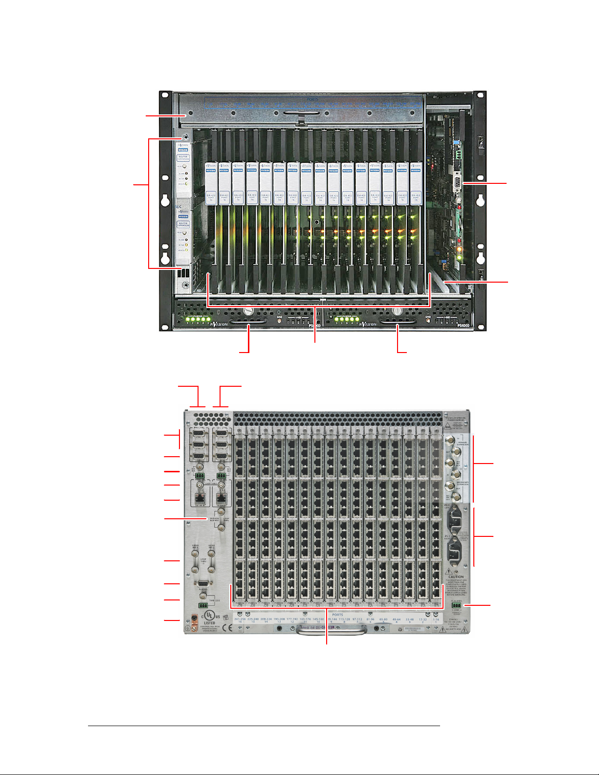
Physically, the NV5256 has an 8RU frame that holds the following items:
• Prerequisites
• Overview
• Installation
• Functions
• Equipment and software properly installed.
• NV9000 requirements met.
• All control panels properly configured.
• 16 I/O cards (RS-422/485 or RS-232)
• 16 RJ-45 backplanes.
• 2 expansion cards (for redundancy).
• 2 control cards (for redundancy).
• 2 power supplies (for redundancy).
A single NV5256 frame provides a 256×256 routing matrix. Two NV5256 frames can be connected
in tandem, using expansion cables, to provide a 512×512 matrix. A frame need not be fully populated. The NV5256 can be as minimal as a 16×16 router.
The following figures show the NV5256 features.
NV5256 Machine Control Router • User’s Guide 3
Page 12
2. Introduction
Overview
Fan Tray
Expansion
Cards (2)
Figure 2-1. NV5256, Front View
Primary Control
Card Ports
Serial Control
Diagnostic Ports
AES Ref.
Inter-Frame Conn.
Ethernet
Power Supply Module
Port s
Port I/O Cards (16)
Redundant Control
Card Ports
Router
Control
Card (diagn.
port)
Empty Control
Card Slot
Power Supply Module
Expansion
Ports
Aux Bus
Main Power
Video Ref.
System Alarms
(T.C. Ref.)
Ground Lug
Port I/O Backplanes (16)
Figure 2-2. NV5256, Rear View
Power Supply
Alarms
4 Rev 1.8 • 08 Jul 11
Page 13
2. Introduction
Overview
I/O Signals
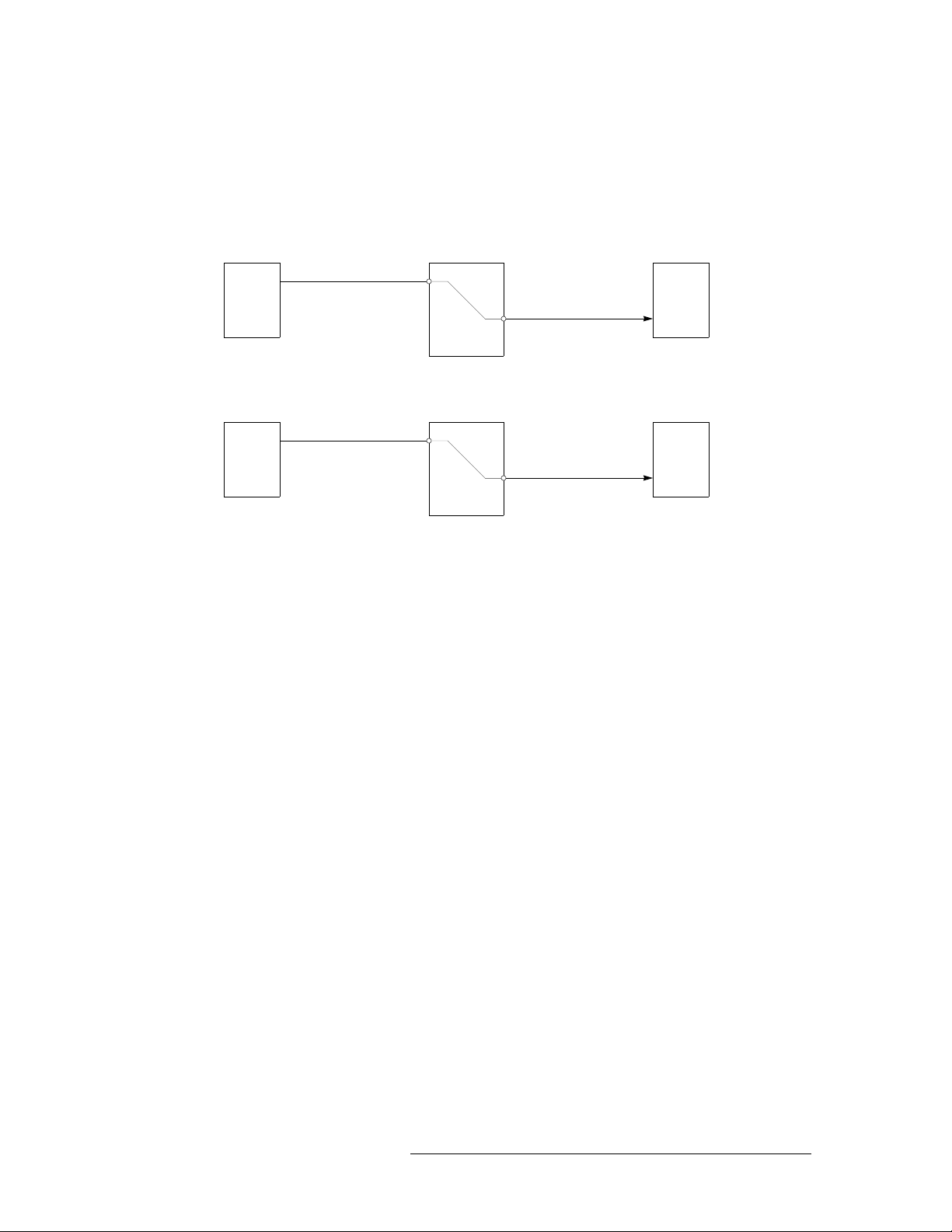
I/O signals are serial (either RS-422 or RS-232) at up to 115.2 kBaud. Signals are bidirectional:
commands in one direction; responses in the other.
A port can be considered a “controlled” port or a “controlling” port.
Controlling device
NV5256
Controlled device
controlling
SRC DST
port
controlled
port
controlling
port
controlled
port
A destination can also be the controlling device:
port
NV5256
controlled
port
Controlling device
controlling
port
Controlled device
controlled
SRC DST
port
controlling
For example, a recording VTR sends signals from an edit list to various source machines in an edit
suite.
In most, if not all, cases a controlling device must communicate with a controlled device and not
another controlling device. (The reason is that a transmitter must connect to a receiver.)
S The Tx-to-Rx connection, of course, depends on the cable. Straight-through cables are consid-
ered preferable.
Router Configuration
The NV5256 router has several configurable options. It supports several signal options that can be
configured for each port.
The router can be (and must be) configured to operate according to your system constraints. You
will need to specify the size of the router matrix, the type of ports, communication parameters, and
so on.
Your router control system must also be configured. In an NV9000 router control system, you will
specify source and destination device names, router names, levels, level sets, and so on.
The NV5256 itself must be initialized through UniConfig.
Router Control
The NV5256 can be controlled by an NV9000 Router Control System. An NV9000 system controls
one or more routers of different types. Central to the system are the NV9000 servers. The NV9000
can include one or more control panels with which operators may perform routes through the
NV5256 and through other routers.
Alternatively, you can use a compatible third-party control system such as the SMS7000.
S Using an SMS7000 control system requires specially configured router control cards.
NV5256 Machine Control Router • User’s Guide 5
Page 14
2. Introduction
Overview
The NV5256 has these control connections:
Router Expansion
Two NV5256 frames can be connected to create an expanded router. Six expansion ports are at the
top right at the rear of the router. There are 6 BNC connections
Router Options
• Ethernet, from an NV9000 router/panel network (through a switch), to primary and redundant
control cards.
• Serial control from primary server and secondary server to primary and secondary control cards
(4 connections).
• Video reference (4 connections). Loop-through for main and redundant reference signal.
• AES reference. Two BNC and two STP connectors for each control card.
• “Node Bus” interface for SMS7000.
• System alarm outputs and power supply alarm outputs
— 3 coming in and 3 going out.
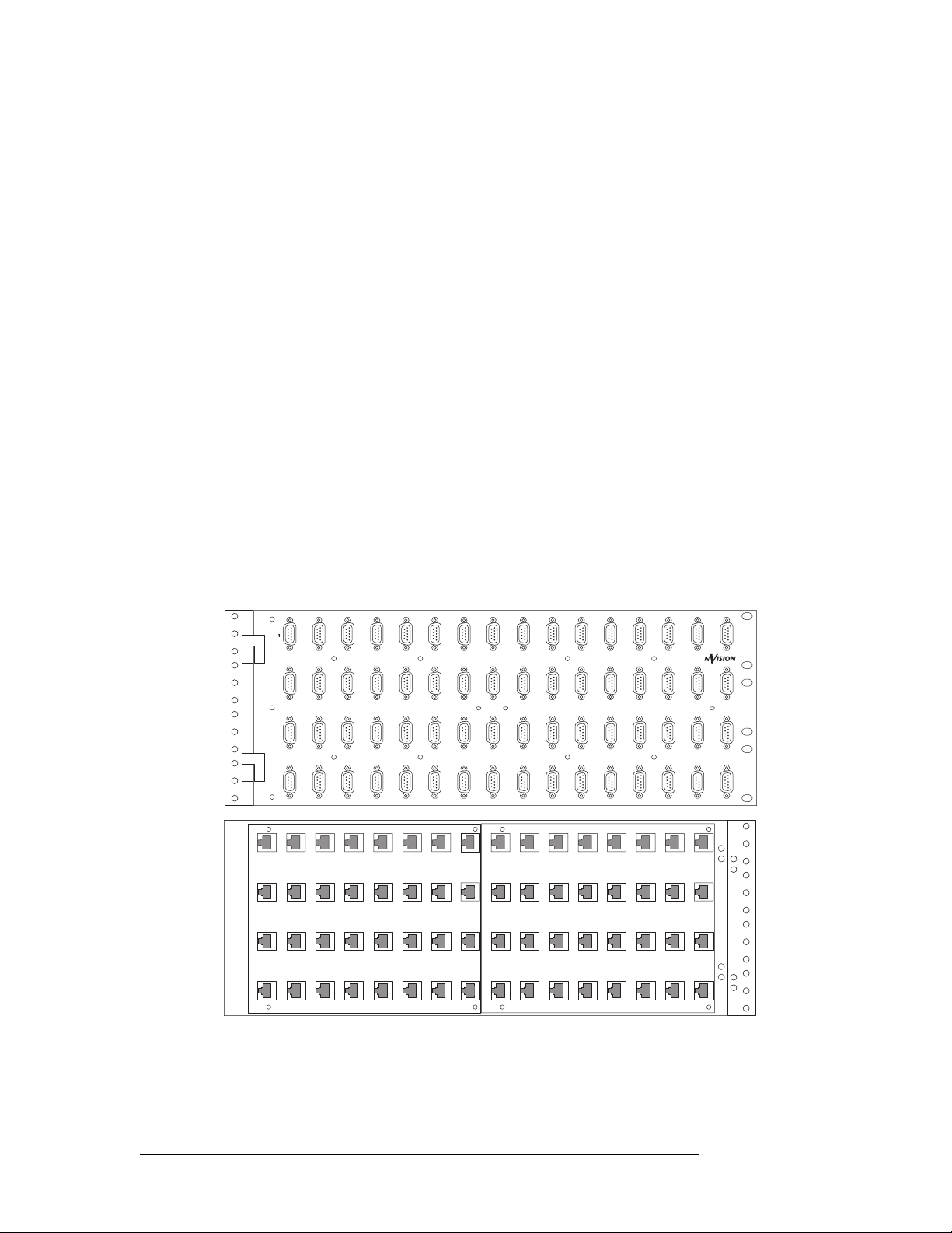
Breakout Panel
A 64-port breakout panel is available that has RJ-45 connectors on one side and DE9 (female) connectors on the other. This panel can make it easier to use DE9 connectors if you prefer them.
2 3 4 5 6 7 8 9 10 11 12 13
MACHINE CONTROL
BREAKOUT PANEL
17 18 19 20 21 22 23 24 25 26 27 28 29
33 34 35 36 37 38 39 40 41 42 43 44 45
49 50 51 52 53 54 55 56 57 58 59 60 61
BP-PORT-64
14 15 16
30 31 32
46 47 48
62 63 64
Front
Rear
The breakout panel is RS-422 only
S Older versions of the breakout panel might not function correctly.
6 Rev 1.8 • 08 Jul 11
Page 15

Functions
2. Introduction
Functions
SMS7000
If you are using an SMS7000 router control system, you will require an SMS7000 mezzanine card
installed on all router control cards.
The NV5256 router can be configured with partitions of 4 types. Each partition is considered a
physical level. The physical levels can be of 4 “signal types.” The signal types accommodate the
different characteristics of Miranda’s NVISION series routers and third-party routers.
Any of the router’s ports can be specified as one of 7 different types, generally configuring the port
as a controlling port, a controlled port, or a port whose type can be changed dynamically.
The port types accommodate (1) the different devices you might have in use and (2) the connection
requirements that differ between RS-422 and RS-232 ports.
The signal types and port types are specifiable as parameters in UniConfig. Those parameters, however, affect the behavior and operating characteristics of the router, which are discussed briefly
here.
See Chapter 4, Configuration
on page 27 for more information.
Signal Types
Four “signal types” are available:
Machine Control Forward Machine Control Broadcast
Machine Control Reverse DataXY
NV5256 physical levels in NV9000 router control systems always are “machine control forward.”
Third-party control systems are “machine control reverse.”
A controlling device sends commands to a controlled device. The controlled device passes
responses (such as status) back to the controlling device. A source device can be a controlling
device or a controlled device. A destination device can be a controlling device or a controlled
device.
When you are configuring some NV9000 control panels, you can create a “source is master” button
that toggles whether the source or the destination is the master (i.e., controlling device).
Some control panels have a broadcast button that allows one source to control multiple destination
devices. (“Source is master” is a requirement for machine control broadcast.)
Machine Control Forward
“Machine control forward” means that the source device is the controlling device.
Machine Control Reverse
“Machine control reverse” means that the destination device is the controlling device.
NV5256 Machine Control Router • User’s Guide 7
Page 16

2. Introduction
Functions
Machine Control Broadcast
This level type applies only to third-party router control systems. Use this level type if you have a
third-party control system and you want to be able to perform broadcast machine control takes.
DataXY
“DataXY” is a type of physical level on which data flow, much like video and audio signals in a
normal X/Y router. There is no concept of command and response on this type of level.
Port Types
Seven port types are available:
Controlling and Controlled
These port settings fix the direction of the router port to “controlling” or “controlled.” The port’s
connection for Tx and Rx is fixed. This allows the port to be routed as a source or destination while
maintaining, for example, Rx on pins 7 and 2 and Tx on pins 8 and 3.
Controlling DTE Master Dynamic
Controlled DCE Slave
S Pins for Tx on a controlling machine are 8 and 3. Tx pins for a controlled machine are 7 and 2.
S For more about machine control data, review the SMPTE 207M standard.
DTE
DTE has the same meaning for RS-232 as “controlling” does for RS-422.
DCE
DCE has the same meaning for RS-232 as “controlled” does for RS-422.
Dynamic
A dynamic port can be a controlling or controlled port depending on whether it is connected to a
master port or slave port. The port’s configuration is dynamic and can change during operation.
Dynamic ports are typically assigned to VTRs.
Master
Any dynamic port connected to a “master” port will be a controlled port.
The NV5256 applies logic to the port direction setting when a master port is connected to a
dynamic port. In this case, the machine at the dynamic port is always controlled and the machine at
the master port is always controlling.
A good example is an Avid editor controlling two VTRs.
Slave
“Slave” means the opposite of “master”: any dynamic port connected to a slave port will be a controlling port.
8 Rev 1.8 • 08 Jul 11
Page 17

2. Introduction
Installation
Summary
In general, a controlling machine must connect, through the router, to a controlled machine. That is
because Tx must connect to Rx and vice versa.
S In NV9000-SE Utilities, when you add the NV5256 router to your system, set ‘Signal Type’ to
‘Machine Control’. Also set both ‘Output Protect’ and ‘Output Lock’ to ‘In Server’.
S In NV9000-SE Utilities, when you configure a control panel, ‘semi-automatic’ is the preferred
setting for ‘XY data routing mode’. This is defined in the SE documentation:
“If the device to be acquired is already in use on the data level, alert the user
user to perform the route by pressing ‘Take’ a second time. If ‘Take’ is not pressed again,
the route is cancelled. If the device is not in use, the take occurs automatically. This is the
recommended mode.”
The alternatives are ‘fully automatic’ and ‘manual’.
S In NV9000-SE Utilities, you have the choice of making “source is master” the control panel
default or not.
— but allow the
Installation
The NV5256 is intended to mount in a standard 19-inch equipment rack. The frame is heavy
(approximately 100
lb, or 45 kg, fully loaded). Enlist the help of several persons during the mount-
ing process.
To help reduce weight, you can remove the power supplies and modules temporarily. Make note of
their location prior to removal. Do not drop or stack the modules.
To mount the equipment frame into a rack:
1 Swing the front door open all the way and then lift it up to remove it.
2 Lift the frame into the desired position within the rack. Have several helpers keep the frame in
position. Or use a jack.
3 Do not use the cards or other internal components as hand holds. Follow anti-static precautions
to protect the circuit boards. The handle on the bottom rear of the frame may be used for lifting
the frame.
4 Install rack screws into the 8 holes provided. It is important to use all 8 screw holes.
5 Replace any assemblies (power supplies, circuit cards) that you removed and replace the front
door.
The front rack-mounting brackets include keyway openings to accept an optional lifting bar. If you
wish, you can obtain a lifting bar by contacting your sales representative or Miranda Technical Support.
NV5256 Machine Control Router • User’s Guide 9
Page 18

2. Introduction
Installation
Mounting
Slot (8 places)
Keyway Slot
(4 places)
Power Supply 1 Power Supply 2
S Warni ng: Make certain that your work area is free of unnecessary objects that block personnel
Rear handle
movement or that might interfere with their footing. Careless handling of the NV5256 frame
could result in personal injury.
S Warni ng: Disconnect power, if it is connected, before mounting the frame in the rack.
S Warni ng: The NV5256 draws cooling air from the front through the door and exhausts it at the
top rear edge of the frame. Make certain that airflow is not blocked at these locations. If air flow
is restricted, overheating may occur. The frame must have its door installed and closed for
proper airflow through the chassis. Filters are located on the inside of the door assembly and
should be maintained regularly.
S Rear panel cover plates (placed in backplane slots that have no backplanes) are essential for
cooling. Although you can remove them temporarily, make sure that unused backplane slots
have cover plates during normal operation.
10 Rev 1.8 • 08 Jul 11
Page 19

3. Detail
Chapter 3 describes the structure and use of the NV5256 Machine Control Router. It presents the
following topics:
Connections
The rear of the router has a bay that holds up to 16 I/O backplanes. Unused backplane slots are generally covered with a plate that improves cooling air flow. Each backplane has 16 RJ-45 connectors. All the backplanes are identical, but the I/O cards are of two types: RS-422 and RS-232.
S Ports on a single card are either all RS-422 or all RS-232.
To the left of the backplanes are a variety of control connectors and reference connectors. To the
right of the backplanes are expansion connectors and power connectors.
• Connections
• Alarms
• Power
• I/O Cables
• Port Cards
• Expansion
• Terminators
• Jumpers
NV5256 Machine Control Router • User’s Guide 11
Page 20

3. Detail
R
1
5
Connections
Control Ports
At the top left portion of the rear of the NV5256 frame are 6 DE9 connectors, and further below
that are 2 Ethernet connectors:
for Primary
Control Card
for Secondary
Control Card
CTRL 1
CTRL 2
Diagnostic
Ethernet
PRI CTRL
AES
REF
1
PRI CTRL
10/100 BT
CTRL 1
CTRL 2
DIAG
LOOPTHRU
NVISION
SEC CTRL
CTRL 1
CTRL 2
DIAG
SEC CTRL
10 B 210 B 2
10/100 BT
LOOP
PORT 16
PORT 16
PORT 16
PORT 16
PORT 16
PORT 16
PORT 16
PORT 16
PORT 16
PORT 16
AES
REF
2
1-4
1-4
5-8
5-8
1-4
1-4
5-8
5-8
1-4
1-4
5-8
5-8
1-4
1-4
5-8
5-8
1-4
1-4
5-8
5-8
S A secondary (router) control card is for redundancy and is not required. If you have an
expanded system (two router frames), make connections only to one frame. The frame to which
you make connections is the “master” frame and it controls the second frame.
Serial Control
The CTRL1 and CTRL2 ports are DE9, female, RS-422. See Control Port Connectors, page 43, for
their pinout information.
PO
You can use these connectors for control using a serial protocol from (1) a primary or secondary
NV9000 router control system, (2) a primary or secondary third-party router control system, or (4)
a router automation system.
Cases:
1 If you are using an NV9000 control system with a serial protocol or if you are using a third-
party control system, connect the primary CTRL1 port to a COM port on the control system’s
server. Similarly connect the secondary CTRL1 port if your router has a secondary control card.
2 If you have a redundant server, connect the primary CTRL2 port to a COM port on the redun-
dant server. Similarly connect the secondary CTRL2 port if your router has a secondary control
card.
3 If you do not have a redundant server, but have an automation system, connect the primary
CTRL2 port to a COM port of the automation system. Similarly connect the secondary CTRL2
port if your router has a secondary control card.
12 Rev 1.8 • 08 Jul 11
Page 21

3. Detail
Connections
Ethernet Control
The Ethernet connectors are used when you have an NV9000 connected using an Ethernet protocol.
Cases:
1 If you are using an NV9000 control system with an Ethernet protocol, connect the primary
Ethernet port to the “Router/Panel” network switch connected to the NV9000 server. Similarly
connect the secondary Ethernet port if your router has a secondary control card.
2 If you have a redundant server, then no router connections are required, but the redundant
server should be connected to the “Router/Panel” network switch.
3 If you have an automation system, connect a COM port of the automation system to either pri-
mary serial port, CTRL1 or CTRL2. Similarly connect a COM port to either secondary serial
port if your router has a secondary control card.
The server’s COM ports must be set up to be compatible with the router’s serial ports— the same
Baud rate, parity settings and so on.
An automation system’s COM ports must also be compatible with the router’s serial ports.
Diagnostic Ports
The DIAG ports are DE9, female, RS-232 or RS-422. See Control Port Connectors, page 43, for
their pinout information.
AES Ref,
BNC
AES Ref,
Phoenix
These ports are for configuration, firmware uploads, and testing. The ports are typically used with
UniConfig to initialize either the primary control card or the secondary control card.
The DIAG ports are not used during normal operation.
See Chapter 4, Configuration
, on page 27, for information about UniConfig and its use.
AES Reference
AES reference is used to “clock-lock” the data traffic between two frames in an expanded router. If
you have a stand-alone router, you do not need AES reference.
If you do have an expanded router, choose one of the following 2 methods:
1 Supply an AES reference to the primary control card of both frames. You can use either connec-
tor. If you have a secondary control card, supply an AES reference to that also.
Use the connectors at the top left portion at the rear of the NV5256 frame:
for Primary
Control Card
AES
REF
1
CTRL 2
DIAG
PRI CTRL
LOOPTHRU
SEC CTRL
See AES Reference Connectors
CTRL 2
DIAG
for Secondary
Control Card
AES
REF
2
on page 43 for the Phoenix pinouts.
1-41-41-41-41-41-41-41-41-41-4
2 Connect the primary AES reference output on the master frame to the primary AES reference
input of the slave frame. If you have redundant expansion cards, connect the redundant AES
reference output of the master frame to the redundant AES reference input of the slave frame.
NV5256 Machine Control Router • User’s Guide 13
Page 22

3. Detail
R
Connections
PORT 16
PORT 16
Use the connectors at the top right portion at the rear of the NV5256 frame:
PORT 16
PORT 16
PORT 16
PORT 16
PORT 16
PORT 16
PORT 16
PORT 16
PORT 16
PORT 16
OUT
IN
PRIMARY
EXPANSION
AES
REF
OUT
IN
1-4
1-4
1-4
1-4
1-4
1-4
1-4
1-4
1-4
1-4
1-4
1-4
SECONDARY
EXPANSION
OUT
AES
REF
OUT
PS 1
See Expansion
on page 24 for additional information.
AES reference
(primary)
AES reference
(secondary)
(The video reference does not lock the cards.)
If the frames in an expanded router are not clock-locked, data errors will occur when the router uses
ports across frame boundaries.
Inter-Frame Communication
At the top left portion of the rear of the NV5256 frame are two 10Base2 (BNC) connectors:
for Primary
Control Card
PRI CTRL
CTRL 1
SEC CTRL
CTRL 1
for Secondary
Control Card
PORT 16
PORT 16
PORT 16
PORT 16
PORT 16
PORT 16
PORT 16
PORT 16
PORT 16
PORT 16
PO
10Base2
AES
REF
1
CTRL 2
DIAG
PRI CTRL
10/100 BT
LOOPTHRU
CTRL 2
DIAG
SEC CTRL
10 B 210 B 2
10/100 BT
AES
REF
2
1-4
1-4
1-4
1-4
1-4
1-4
1-4
1-4
1-4
1-4
The 10Base2 connectors are used to connect two frames in an expanded router. If you have a standalone router, you do not need the connectors.
If you have an expanded router, connect the primary 10Base2 connector on one frame to the primary 10Base2 connector on the other.
Do not connect the secondary 10Base2 connectors, even if you have a secondary control card.
14 Rev 1.8 • 08 Jul 11
1
Page 23

3. Detail
1
Connections
S In older routers, stand-alone termination is required. In newer routers, it is not. In an older sys-
tem, place 50Ω terminators on both connectors.
In any expanded router, place 50Ω terminators on unused 10Base2 connectors.
Aux Bus
At the middle left portion of the rear of the NV5256 frame are 2 ‘NVISION Aux Bus’ (BNC) connectors:
Aux Bus
Video
Reference
10/100 BT
NVISION
AUX BUS
10/100 BT
LOOP
THRU
If you are using an SMS7000 router control system with the NV5256, connect the SMS7000 to the
NVISION Aux Bus (a.k.a. Node Bus) connector.
The NV5256 has two aux bus connections. The connection is loop-through: you can pass the
SMS7000 “node bus” control signals on to another device if it is required. You can connect a
redundant control system on the “node bus.”
If you are using an SMS7000 control system, terminate the “node bus” with 75Ω terminators.
S Using an SMS7000 requires an SMS7000 mezzanine card installed on each router control card.
Jumpers J4 and J6 must be set. See Jumpers
, page 26, for detail.
Video Reference
At the lower left portion of the rear of the NV5256 frame are 4 Video Reference (BNC) connectors:
VIDEO
REF 1
LOOP
THRU
(2)
VIDEO
REF 2
9-129-129-129-129-129-129-129-129-129-12
5-5-85-85-85-85-85-85-85-85-85-8
9-
The NV5256 provides video reference connections ‘VIDEO REF 1’ and ‘VIDEO REF 2’. These
connections allow you to synchronize port switches with a video frame’s switch point. The video
reference can be NTSC, PAL, or tri-level sync.
S Tri-level sync is not supported on older EM0374 control cards.
At least one video reference connection must be connected. Otherwise, the control card’s front red
LED remains lit and takes will not occur at defined switch points.
Redundant Reference
There are two video reference connections. You can use the reference connectors in 2 ways:
• Single reference.
• Redundant reference.
NV5256 Machine Control Router • User’s Guide 15
Page 24

3. Detail
-
6
T
T
Alarms
Time-Code
Reference
A redundant reference uses identical, but distinct, reference signals. If one reference source
fails, the other acts as a fail-over.
S The NV5256 does not support “dual reference” mode.
If you have an expanded router, use the loop-through connector to connect the master and slave
frames. Terminate any reference chains with 75Ω terminators.
Time Code Reference
At the lower left portion of the rear of the NV5256 frame are 2 connectors for time-code reference:
ALARMS
13-16
13-16
13-16
13-16
13-16
13-16
13-16
13-16
13-16
TIMECODE
13-16
PORT 16
PORT 16
PORT 16
PORT 16
PORT 16
PORT 16
PORT 16
PORT 16
PORT 16
PORT 16
POR
13-
Alarms
Alarm
Connector
241-256
16
225-240
15
209-224
14
193-208
13
177-192
12
161-176
11
145-160
10
129-144
113-128897-112781
9
The NV5256 does not use time-code reference. You can ignore these connectors.
Two alarm connectors (system, and power-supply) allow you to construct alarm indicator circuits
of your own.
System Alarm Outputs
At the lower left portion of the rear of the frame is a female DE9 connector for system alarms:
ALARMS
13-16
13-16
13-16
13-16
13-16
13-16
13-16
13-16
13-16
PORTS
TIMECODE
This connector allows you to create alarm circuits of your own.
The internal alarm signalling is provided by solid-state relays that turn on in the event of an alarm
condition. Table 3-1 describes the individual alarm connections:
13-16
PORT 16
PORT 16
PORT 16
PORT 16
PORT 16
PORT 16
PORT 16
PORT 16
PORT 16
PORT 16
POR
13-
Table 3-1. Alarm Signals
Pin Signal Description Possible Alarm Condition(s)
1, 9 Alarm Com Common Common connection for all alarm signalling pins. This is a
“return” for an external circuit.
2 Alarm 1 Major alarm Missing reference inputs, possible failure of fans or over-
temperature conditions on one or more modules.
3 Alarm 2 Minor alarm Any of alarms conditions 3, 4, 5 or 6.
4 Alarm 3 Power supply Main power supply module is missing.
5 Alarm 4 Video reference Missing video reference signal 1 or 2 (if applicable).
16 Rev 1.8 • 08 Jul 11
Page 25

3. Detail
Alarms
Table 3-1. Alarm Signals
Pin Signal Description Possible Alarm Condition(s)
6 Alarm 5 AES or time code
reference
7 Alarm 6 Fans or internal
Temperature
8 Alarm 7 Controller health Control card(s) are not “healthy.”
S Pins 2 through 8 signal alarm conditions that are signalled on either the primary or secondary
control cards. The connector offers no way to distinguish which control card has an alarm.
Figures 3-1 and 3-2 show sample system-level alarm circuits. (You can use alarm signalling
devices other than LEDs, or in addition to LEDs.)
Missing AES reference signals or loss of system clock. (AES
is optional. Note: AES does not generate alarm in standalone
case.)
Failure of any one of three fans. Over-temperature conditions
on one or more modules.
External Power
1
Internal alarm signals normally
clear, controlled by software
COM
Figure 3-1. Simple Alarm Circuit
30VDC max, 150mA max
Normally off, the LEDs
turn on to indicate failure
Here, LEDs are all off unless a failure occurs. The LED for the failed circuit turns on.
This is an alarm circuit that can drive heavier loads, not just LEDs.
Customer-supplied relay
contacts NC, (but open during
alarm condition)
External Power,
30VDC max, 150mA max
Normally on, the LEDs turn
off to indicate failure
1
Internal alarm signals normally
clear, controlled by software
COM
Figure 3-2. Alarm Circuit to Drive Loads
In this case, the LEDs are normally on and turn off when a failure occurs.
CAUTION: If the alarm load is inductive, protect the internal alarm relay contacts with a reversedbiased diode. The external supply voltage should not exceed ±30VDC and the load resistors should
be sized to limit contact current to less than 150mA.
NV5256 Machine Control Router • User’s Guide 17
Page 26

3. Detail
TO REDUCE THE RISK
9
Power
13-16
PORT 16
PORT 166
2
161-176
11
145-160
Power Supply Alarms
At the lower right portion of the rear of the NV5256 frame is a Phoenix 3-pin connector for power
supply alarms:
OF ELECTRIC SHOCK,
DISCONNECTT WO
POWER SUPPLYCORDS
BEFORE SERVICING.
13-16
13-16
13-16
13-16
13-16
13-16
13-16
13-16
13-16
13-16
PORT 16
PORT 16
PORT 16
PORT 16
PORT 16
PORT 16
PORT 16
PORT 16
PORT 16
PORTS
113-128897-112781-96
129-144
10
9
6
65-80549-64
4
33-48317-32
1-16
1
2
The NV5256 has alarm outputs for each power supply installed in the frame. An internal solid-state
relay is provided for each supply. The relay turns on when there is an alarm condition.
Figure 3-3 shows suggested alarm circuit implementations. You can use signalling devices other
than LEDs or in addition to LEDs. For example, you can operate a buzzer or other audible alarm to
warn operators of a potential problem.
PS ALARMS
12COM
NORMALLY
CLOSED
E146905
90-130/180-250V~
7.5A/3.75A
50/60Hz
660 WATTS MAX
PS Alarm
Connector
Power
30VDC max, 150mA max
External Power
Normally off, the
LEDs turn on to
indicate failure
Internal alarm signals
normally clear, controlled
by software
12
COM
Extermal Power,
30VDC max, 150mA max
Customer-supplied relay
contacts NC (and closed
during normal operation)
Normally on, the
LEDs turn off to
indicate failure
Internal alarm signals
normally clear, controlled
12
by software
Figure 3-3. Power Supply Alarms
CAUTION: The voltage of the external power supply for alarm signalling should not exceed
±30VDC. Resistors should be sized to limit the current through each internal alarm contact to less
than 150mA.
If the load is inductive, the alarm contacts should be protected with a parallel, reverse-biased diode.
The NV5256 has two power supply bays (and two power connectors) to support redundancy. Only
one power supply is actually required.
18 Rev 1.8 • 08 Jul 11
Page 27

3. Detail
REF
9
Power
Connectors
At the middle right portion of the rear of the NV5256 frame are 2 AC connectors:
OUT
PS 1
LEFT
5-8
5-8
5-8
5-8
5-8
5-8
5-8
5-8
5-8
5-8
5-8
5-8
PLEASE READ
INSTRUCTION
MANUAL BEFORE
PS 2
CONNECTING
EQUIPMENTTO
RIGHT
9-12
9-12
9-12
9-12
9-12
9-12
9-12
9-12
9-12
9-12
9-12
-12
THE MAINS
The NV5256 frame has one (IEC) 3-conductor power connection for each of its 2 power supplies.
These should be connected to a 90–130VAC or 180–250VAC 15A grounded circuit wired in accordance with local electrical codes.
Fuses for both AC power inputs are located on their respective power supplies. Ensure that the fuse
ratings comply with specific requirements in your area. A 7.5A fuse is required for 110/120VAC
applications. For 220/240VAC operation, a 3.75A fuse is required.
AC connector
for PS 1
AC connector
for PS 2
For increased protection against loss of power, we suggest that each power supply be connected to
a separate branch circuit. A wire bail can be used to grip the power cable and hold it in place to
reduce the possibility of accidental loss of power.
The power cords represent the only means of disconnecting main power from the NV5256. Make
sure to clearly mark the line side power connection with its function so that in the event of an emergency, power can be disconnected quickly. Make sure to disconnect both power cords before servicing any internal frame components.
Power Supply
The PS61001 power supply accepts a wide range of AC input voltages and produces five +48 VDC
outputs. Each of the five circuits producing the +48 volt outputs is identical. The power supply
automatically senses the AC input voltage (90–130VAC or 180–250VAC) and adjusts itself to
maintain a relatively constant DC output. You do not have to select the voltage. The five regulated
outputs are directed to the various regulators that produce the DC voltages required by the local circuits.
Each +48VDC output powers one of the five green LEDs and output test points on the front of the
power supply. Under normal operation, all five LEDs should be on. If any is not, it is likely that the
corresponding branch circuit has failed. When the power supply output voltages are measured at
the test points, the voltage should be approximately +48 VDC under a full load. If modules have
been removed from the frame or options are not installed, some or all of the test point voltages
could be somewhat higher than +48 VDC.
1. Older master control frames in the field might still use PS6000 power supplies.
NV5256 Machine Control Router • User’s Guide 19
Page 28

3. Detail
-
6
13
T
13 16
13 16
13 16
13 16
13 16
13 16
13 16
13 16
13 16
13 16
Power
There are four low-speed fans located at the front edge of the power supply. They pull a small quantity of air across the internal heat sinks.
The top power connector on the rear panel corresponds to the power supply on the left and the bottom connector corresponds to the power supply on the right (as you face the front of the frame).
Ground Lug
Ground Lug
PORT 16
RT 16
1-4
At the lower left portion of the rear of the NV5256 frame is a ground lug:
TIMECODE
CONTROL NO. 9K50
PROFESSIONAL
VIDEO/AUDIO
PORT 16
241-256
16
PORT 16
225-240
15
PORT 16
209-224
14
PORT 16
193-208
13
PORT 16
177-192
12
PORT 16
161-176
11
PORT 16
145-160
10
PORT 16
PORTS
129-144
113-128897-112781
9
PORT 16
PORT 16
POR
Connect this “lug” to earth ground using 8–14 AWG wire.
Expansion Connectors
At the top right portion of the rear of the NV5256 frame are 6 Expansion (BNC) connectors:
FUSES LOCATED ON
POWER SUPPLIES
T 8.0A 250V
FOR 90-130V~
T 6.3A 250V
FOR 180-250V~
PORT 16
PORT 16
PORT 16
PORT 16
PORT 16
PORT 16
PORT 16
PORT 16
PORT 16
PORT 16
1-4
1-4
1-4
1-4
1-4
1-4
1-4
1-4
1-4
1-4
1-4
PS 1
LEFT
IN
PRIMARY
EXPANSION
OUT
AES
REF
OUT
IN
SECONDARY
EXPANSION
OUT
AES
REF
OUT
Expansion
Connector
See Expansion
on page 24.
20 Rev 1.8 • 08 Jul 11
Page 29

I/O Cables
3. Detail
I/O Cables
All ports are serial, either RS-422 or RS-232, operating at up to 115.2kBaud. The backplane interface is RJ-45. Each RJ-45 port on each port backplane has the following pinout:
1 Gnd
Controlling
Port
1
8
2 n.c.
3
4
5
6
7 Gnd
8 Gnd
Tx +
Rx
Rx +
Tx
It use 4 wires whose usage is controlled by the following circuit. The port can be configured as
“controlling” or “controlled” when the port’s I/O card is RS-422/485 and DTE or DCE when the
port’s I/O card is RS-232. That is because the definition of the port can be reversed during configuration or during operation. This is the circuit:
Controlled
Port
Rx +
Tx
Tx +
Rx
input data
output data
Select Input = A Ena
A Ena
A
B
A Ena
+
Rx
Tx
+
Rx
Tx
RJ-45
3
A
6
5
B
4
When Tx A is enabled (A Ena), Rx B
is selected and the port passes Rx B
data;
Tx B is enabled when Tx A is disabled
(A Ena
passes Rx A data.
These are the functions of the pins:
RS-422 RS-232
Pin
Controlling Controlled DTE DCE
3 Tx+ Rx+ Tx Rx
4 Rx– Tx– n.c. n.c.
5 Rx+ Tx+ Rx Tx
6 Tx– Rx– n.c. n.c.
(The other pins are grounded except for pin 2 which is not connected.)
Breakout Panel
). Rx A is selected, and the port
If you are using the BP-PORT-64 breakout panel, you might need to know the mapping of the signals from the RJ-45 side to the 9-pin (female) side. The breakout panel is RS-422/485 only. See
Breakout Panel
NV5256 Machine Control Router • User’s Guide 21
on page 6 for an illustration.
Page 30

3. Detail
I/O Cables
This is the RJ-45 to DE9 mapping for RS-422:
RJ-45 DE9
1
2
to NV5256 backplane to your device
1
8
3
4
5
6
7
8
1
2
3
4
5
6
7
8
9
1 Gnd
2 n.c.
3
4
5
6
7 Gnd
8 Gnd
This cable wiring is applicable whether the port is a controlling port or controlled port.
S Older breakout panels might have incorrect wiring. Contact Miranda if your breakout panel
does not function correctly.
1
6
9
5
RS-232 Cables
If you make your own RS-232 cables, follow this pattern:
RJ-45 DE9
1
2
to NV5256 backplane to your device
1
8
3
4
5
6
7
8
1
2
3
4
5
6
7
8
9
1 Gnd
2 n.c.
3
4 n.c.
5
6 n.c.
7 Gnd
8 Gnd
This cable wiring is applicable whether the port is DTE or DCE.
(Note: Use either pin 7 or pin 8 of the RJ-45 for ground. It is not necessary to use both.)
General Notes
1
6
9
5
Any DE9-to-DE9 cables you might use will be straight-through.
22 Rev 1.8 • 08 Jul 11
Page 31

Port Cards
3. Detail
Port Cards
The NV5256 has slots for 16 port I/O cards. Each card supports 16 inputs from its corresponding
backplane. There are two types of port cards:
• The EM0503-01 module, supporting RS-422/485.
• The EM0503-50 module, supporting RS-232.
Other than this distinction, the cards are functionally identical. You can install any port card in any
slot that is useful to your system design.
S The NV5128 frame and its I/O cards are nearly identical in appearance to the NV5256 frame
and its I/O cards. Therefore, the NV5256 cards and slots are keyed so that you cannot successfully insert an NV5128 card into the NV5256 frame.
LEDs
Five LEDs are on the front of the card. (Note that there is metal card extender in front of the card.
The LEDs are nevertheless visible.) There names and functionality are as follows:
Name Color Function
Alarm Red A power rail is under voltage by 10% or more.
Power Green The power rails are good.
FGPA Loaded Yellow The FPGA has loaded properly.
COM Good Green Communication with the router control card is good.
COM Bad Red Communication with the router control card is bad.
The LEDs are listed in the order they appear at the front of the card.
Under normal operation, the ‘Power’ light is green, the ‘FPGA loaded’ light is yellow, and the
‘COM good’ light is green. The other lights are off.
Another LED
frame’s expansion link is invalid. This LED is red. It lights when the frame’s expansion cards are
absent or when the frame receives errors from the expansion card. In a stand-alone router, this LED
will be on.
— serial link error — exists in the center of the board. This LED indicates whether the
NV5256 Machine Control Router • User’s Guide 23
Page 32

3. Detail
PS 1
PRIMARY
EXPANSION
SECONDARY
EXPANSION
IN
OUT
AES
REF
OUT
IN
AES
REF
OUT
OUT
Expansion
Expansion
The NV5256 can be expanded to a maximum of 512 ports. To accomplish this, interconnect two
NV5256 frames. The frames share each other’s input space. The first frame receives commands
from the router control system and acts as the master to the second frame.
The interconnect is simple and uses the frame expansion connectors at the back of the frame.
NV5256, SlaveNV5256,Master
Ports 1256 Ports 257512
Exp. In
Exp. Out
Primary
AES Ref
Exp. In
Secondary
Pri. AES Ref In
Sec. AES Ref In
10/100BaseT
Exp. Out
AES Ref
10Base2NV9000
Belden
8281
50W coax
Exp. In
Exp. Out
AES Ref
Exp. In
Exp. Out
AES Ref
Pri. AES Ref
Sec. AES Ref
10Base2
Primary
Secondary
Figure 3-4. Expansion Connectors and Expansion Connections
The frame expansion connectors are driven by the frame expansion cards (EM0502-00) in the
frame. A frame really requires only one expansion card; the second is recommended for redundancy. If both cards and links are installed, the frame will switch from one expansion link to the
other if the current link goes bad.
A frame expansion card multiplexes (TDM) the local frames inputs and sends them out the frame
expansion “Out” port to the other frame. It receives the other frame’s inputs from the “In” port.
Connect the primary input on the master frame to the slave frame’s primary output. Connect the
primary output on the master frame to the primary input on the slave frame. If you have a redundant
expansion card, connect the secondary expansion connections the same as the primary connections.
The expansion cards have built-in redundancy control. Each card reports its own health to the other
card and to the router control card. The first healthy card to start up during initial boot takes over
the expansion link and is the main transmitter and receiver. If, at any time, the link becomes
“unhealthy,” the other expansion card takes over the expansion link if it is healthy.
You can use 75Ω Belden 8281 cable, up to 250 meters, to make these connections.
The Expansion Card
The NV5256 has 2 slots for expansion cards. A stand-alone router requires no expansion card. One
card is required for expansion. The second expansion card provides redundancy.
Release Switch
An expansion card has a front panel reset switch. It forces the active card to release, so that the
24 Rev 1.8 • 08 Jul 11
other expansion card can take over.
Page 33

3. Detail
Terminators
LEDs
Three leds are on the front of the card. Their name and functionality are as follows:
Name Function
Alarm Indicates when the serial link is not error-free or the P.S. is bad.
Active Indicates the card is healthy and supplying the Frame TDM stream to the frame.
Health Indicates Good power, Good Serial link, FPGA loaded
A red ‘serial link error’ LED is in the center of the card. This LED indicates whether the frame
TDM link is invalid (has data bit errors).
Clock Lock
For the expanded router to operate correctly, the frames must be “clock-locked” to each other. The
following is a list of ways to accomplish the clock locked frames.
1 Supply an AES reference to both frames.
2 Connect the primary AES reference output on the master frame to the primary AES reference
input of the slave frame. If you have a redundant expansion card, connect the secondary AES
reference output of the master frame to the second AES reference input of the slave frame.
The video reference does not lock the cards.
If the frames are not clock-locked, data errors will occur when the router uses ports across video
frame boundaries.
Inter-Frame Communication
The expansion connections transport machine control data.
Additionally, the two frames must communicate with each other. Connect one 10Base2 connector
on the master frame, with 50Ω coaxial cable, to a 10Base2 connector on the slave frame. Place a
50Ω terminator on each unused 10Base2 connector.
Terminators
10Base2
The NV5256 ships with two 50Ω terminators for each frame. The terminators are required for an
expanded router.
S In older routers, termination for a stand-alone router is required. In newer routers, it is not.
If you have an expanded router, use terminators as described under Inter-Frame Communication
.
Ethernet
The NV5256 ships with 1 Ethernet terminator for each router control card. These terminators are
required if you do not use Ethernet (for example, if you are using a third-party router control sys-
NV5256 Machine Control Router • User’s Guide 25
Page 34

3. Detail
Jumpers
Jumpers
tem). The router control cards will not come out of reset without either an Ethernet connection or
an Ethernet terminator.
(The terminator looks like an RJ-45 plug without the cable.)
Plug a terminator into the Ethernet port of every router control card that does not use Ethernet.
The control card has several jumper sets:
ON
J29
GND
CONSOLE
DIAG
JUMPER
OFF
J28
Rx
Tx
SICK
LED7
ACTIVE
LED8
HEALTH
LED9
SMS7000
U190
SBUS
J1
TXDRXD
10B2
SBUS
J2
10B2
SBUS
J1
TXDRXD
10B2
SBUS
J2
10B2
SMS7
SBUS
J4
SMS7
SBUS
J6
TIME CODE
110
75
J12
HI Z
SMS7
SBUS
J4
SMS7
SBUS
J6
J13
AESREF2
J16
AESREF1
Mezzanine Card
(Optional)
PC043602
J13
AESREF2
J16
AESREF1
Set impedance jumpers (J12, J13, J16) as follows:
For Phoenix 110W, place both jumpers on the upper 4 pins.
For BNC 75W place both jumpers on the middle 4 pins.
For Phoenix Hi-Z, place both jumpers on the bottom 4 pins.
For BNC Hi-Z, set the left jumper on the bottom 2 pins and
set the right jumper on the middle 2 pins
Figure 3-5. EM0374 Router Control Card Jumpers
Table 3-2 describes the jumpers appropriate to the NV5256. Jumpers not listed should be left in the
factory position:
Table 3-2. EM0374 Jumpers
Jumper Settings
J1, J2 Frame-to-frame communication. Leave these jumpers in the 10B2 position. The control card
(and therefore the NV5256) does not support SBus yet.
J4, J6 SMS7000 option. Place the jumpers in the SMS7 position to use a SMS7000 control system
and the Node Bus connectors. Otherwise, leave the jumpers in the SBus position. (SBus is not
supported.)
Note: Using an SMS7000 requires an SMS7000 mezzanine card to be installed.
J13, J16 AES reference termination options. See Figure 3-5 for jumper settings.
26 Rev 1.8 • 08 Jul 11
Page 35

4. Configuration
Chapter 4 describes the structure and use of the NV5256 Machine Control Router. It presents the
following topics:
Summary
• Summary
• UniConfig—Stage 1
• UniConfig—Stage 2
There are several phases to configuring an NV5256 router.
1 Use UniConfig (first) to define its network address and (second) to define its basic partitions
and specify its port types.
2 Then, use the NV9000 “browser” application or NV9000-SE Utilities to define its device con-
nections and “add” the router to the router control system.
We discuss UniConfig briefly. Refer to the NV9000 User’s Guide and the NV9000-SE Utilities
documentation for additional information.
UniConfig runs on a PC that you will connect to your router control card. In all cases, to launch
UniConfig, do either of the following:
1 Double-click UniConfig.exe in the software folder. The default pathname is:
C:\nvision\utils\UniConfig.exe
2 Double-click a UniConfig icon on your desktop:
UniConfig— Stage 1
You must assign IP addresses to the NV5256’s router control card(s) before you proceed with other
configuration steps.
1 Connect an RS-232 cable from your PC’s COM port (generally COM1) to the DE9 connector
(female) at the front of a router control card.
NV5256 Machine Control Router • User’s Guide 27
Page 36

4. Configuration
UniConfig—Stage 1
2 Launch UniConfig. In the Communications menu, check ‘Serial’:
3 Then choose ‘Setup’ from the Communications menu, The following window appears:
4 From the Windows menu, choose ‘Configuration’. The following window appears:
Specify your PC’s COM port. Choose 9600 for the Baud rate.
Click ‘Read All’ to obtain the NV5256 parameters and the router control card’s software and
firmware versions.
28 Rev 1.8 • 08 Jul 11
Page 37

5 UniConfig now displays NV5256 data:
4. Configuration
UniConfig— Stage 1
Asterisks (*) indicate which modules are in effect. (APP1 should indicate that it is an NV5256
application. PLD0 should indicate that it is an NV5256 PLD.)
6 Enter the IP address for this NV5256 control card. Also enter the IP subnet mask. The mask
should always be 255.255.255.0. Make sure Ethernet control is enabled.
7 If you have a standalone NV5256 (256×256) choose ‘Standalone’ at the top right.
8 If you have an expanded NV5256 (2 frames for a 512×512 matrix) choose ‘Master’ when you
are configuring a control card in the “master” frame. Choose ‘Slave’ when you are configuring
a control card in the ‘slave’ frame. (You will have to designate one frame as the master.). The
display changes according to which option you selected:
S The physical levels section will be disabled (greyed out) when you choose ‘slave’.
NV5256 Machine Control Router • User’s Guide 29
Page 38

4. Configuration
UniConfig—Stage 2
9 Populate the physical level section according to the requirements of your system. There are sev-
eral options, especially concerning signal type. This is an example:
See Signal Types
10 After specifying the physical levels, go back to the ‘Expansion’ section, and verify that you
have chosen the right option (standalone, master, or slave) and that you have entered the correct
range of inputs and outputs for the option you have chosen.
11 When everything is correct, click ‘Write All’ (next to ‘Read All’) to send the configuration data
to the NV5256. Now the router control card has its IP address and its basic partitioning.
12 Repeat this entire process for each router control card in each NV5256 frame. The redundant
control card in any frame should be configured the same as the primary control card.
S You can ignore the ‘Card Address’ field. It is not used.
You can now proceed to stage 2. You will rarely, if ever, repeat stage 1.
UniConfig— Stage 2
When stage 1 is complete, you can perform more detailed configuration and you can use a higher
speed connection to do so. You can use the Ethernet connection to the control card or you can use
the ‘DIAG’ serial port for the control card. Both are at the rear of the NV5256.
If you are running UniConfig on an NV9000 server, the Ethernet connection should already have
been established. If you are using a separate PC to configure the router, you might need to reconfigure your PC’s Ethernet port. This can be a nuisance on a separate PC. The serial alternative is easy
and very fast, but not quite as complete.
on page 7 for more information.
To use the DIAG port (which typically operates at 38,400
the same Baud rate as the DIAG port.
In stage 2, you will configure the port type for each port. (You are advised to plan your connections
carefully beforehand.)
You can also perform routes in UniConfig if you wish to test the operation of the router.
Stage 2 requires some knowledge of the different port types and the semantics of machine control
routing.
Baud), you will use a PC COM port set to
Configure Port Types
Follow these steps to configure the port types:.
1 Connect either to the DIAG port of the router control card you are configuring or to its Ethernet
port. Launch UniConfig, choose ‘Configuration’ from the Window menu, and click ‘Read All’
to get the control card’s current configuration.
30 Rev 1.8 • 08 Jul 11
Page 39

S Always read the current configuration before making changes.
2 Choose ‘Machine Control Port Setup’ from the Window menu:
4. Configuration
UniConfig— Stage 2
Click ‘Read’ to get a list of port types. Initially, all ports are of the default type.
3 Select one or more of the ports in the list and right-click your mouse. The context menu that
appears contains a list of port types:
Choose one of the types to apply to your selection and release the mouse button.
See Port Types
4 Click the ‘Write’ button at any time to send the port type definitions to the NV5256.
5 The ‘Machine Control Port Setup’ window also has an option where you can specify the take
delay:
on page 8 for information on port types.
NV5256 Machine Control Router • User’s Guide 31
Page 40

4. Configuration
UniConfig—Stage 2
Perform Takes in UniConfig
UniConfig is not intended to be a “GUI.” However, you can perform limited takes to test the operation of the router.
Follow these steps to perform individual takes in UniConfig:
S You can do this with a serial connection, but it is more effective to do this with an Ethernet con-
1 Launch UniConfig. If your installation permits, choose ‘Ethernet’ from the Communications
2 Choose ‘Connections’ from Window menu:
Enter a number in this field. The number is typically 1 or some small value. The delay is the
time between the “break” of the previous connection and the “make” of the new connection (as
a number of frames).
nection.
menu. Otherwise, use a serial connection. Select and read the NV5256 configuration.
Click ‘Read Outputs’ to obtain the current crosspoint status. You can specify the range of outputs to read.
The table shows the status for each output. Remember that ports are both inputs and outputs, so
port 10, for instance, appears in the input column and the output column. The ‘LPR’ column
represents the “lock, protect, and release” status of the ports. The term “tristate” indicates that
the port is disconnected.
3 To perform a take is simple: specify an input and output in the ‘Single Take’ area at the top left
and click ‘Execute’. Then click ‘Read Outputs’. The example above shows input 10 taken to
output 3 where the ports are “machine control reverse.” That is to say, port 3, the output, is for
the controlling device and port 10, the input, is for the controlled device.
32 Rev 1.8 • 08 Jul 11
Page 41

4. Configuration
UniConfig— Stage 2
If the ports’ physical level were designated machine control forward, port 3 (the output) would
be the controlled device, and port 10 (the input) would be the controlling device.
4 It is not possible to write any of this to the NV5256 control card, because these takes are not
part of its configuration.
During normal operation, users perform NV5256 takes at NV9000 control panels and automation systems can perform takes using one of the router’s serial connections.
Other
If you chose to perform takes in UniConfig using a serial connection, the port status window shows
the information is a somewhat less “elegant” format:
There is no “LPR” status, and the “tristate,” “controlled,” and “controlling” states are rendered as
bit patterns.
NV5256 Machine Control Router • User’s Guide 33
Page 42

4. Configuration
UniConfig—Stage 2
34 Rev 1.8 • 08 Jul 11
Page 43

5. Maintenance
Chapter 5 provides instructions regarding maintenance. It discusses the following topics:
• Routine Maintenance
• Intake Air Filter Cleaning
• Battery Replacement
• Fuse Replacement
• LED Status Indicators
Routine Maintenance
The NV5256 requires very little in the way of routine or preventative maintenance. Other than
cleaning the fan air intake filter, all that is required is periodic inspection of the system to make sure
no failures have occurred.
You might want to examine the system’s LED Status Indicators
tem is operating normally and to make sure that air flow to the power supply fans is unobstructed.
Caution Only qualified service personnel should perform procedures in this section.
Periodic Inspection
Periodically inspecting the NV5256 for signs of trouble is the best way to prevent unplanned outages. Begin the inspection at the front of the frame. Open the door to the matrix and make these
observations.
occasionally to ensure that the sys-
1 Check the +48VDC LEDs on the front of the PS6000 power suppl(ies). An LED that is off or
very dim indicates a failed or failing supply.
2 Place your hand lightly across the air intakes on the front of the power supplies. You should feel
slight air movement that indicates that the internal cooling fans are running. Use a flashlight to
verify that the fan blades are rotating.
3 Examine each I/O card and verify that none of the red alarm LEDs are illuminated. Normally,
the green and yellow LEDs are illuminated. See LED Status Indicators
4 Examine the router control card(s) and verify that the green and yellow LEDs are illuminated
on the active controller, and that the green LED is on for the standby controller (if you have
one). Verify that the ‘low battery’ LED is off. See LED Status Indicators
5 Inspect the air intake filter located in the door. If the filter is dirty or clogged, clean it. Refer to
Intake Air Filter Cleaning
Next, move around to the rear of the matrix frame.
NV5256 Machine Control Router • User’s Guide 35
on page 36, next, for instructions.
on page 38, following.
on page 38, following.
Page 44

5. Maintenance
Intake Air Filter Cleaning
1 Ensure that there are no missing backplane cover plates. Cover plates (used where there are no
backplanes installed) are required for proper cooling in the frame.
2 Place your hand near the air exhausts (at the top). You should feel strong, evenly distributed air
pressure across the entire opening.
3 Check cable connectors for any sign of unseating.
4 Verify that one or both AC cords are firmly seated at both ends. Make sure that the power cord
retainers on the rear of the frame are in place.
Intake Air Filter Cleaning
The air intake filter is located on the front door assembly of the NV5256. Slide the filter up and to
the right to remove it. The process might be easier if you remove the entire door. To remove the
door, simply open the door and lift it straight up. The router can be operated safely with the door
removed for short periods of time.
Note Be sure to replace and close the door when you are done. The door ensures that
air entering the frame is properly filtered.
If the filter is only lightly contaminated with debris, remove loose debris and dirt with a vacuum
cleaner or by blowing air from the clean side to the dirty side. For filters that are badly clogged, a
rinse with cold water might prove effective. You can wash the filter with warm water and mild
detergent. Make sure the filter is completely dry before re-installing it.
Battery Replacement
A CR2330 lithium coin cell is located on the front edge of the router control card. This battery provides power to maintain the memory contents when power is lost.
If the router control card is continuously powered, the battery should last for several years or more.
If the router control card is frequently powered down, the battery should be replaced every 6
months. A red LED, located directly above the battery holder, illuminates when the battery is low.
The battery can be replaced while the router control card is powered up and operating. Simply pull
the battery from its holder to remove the spent cell. Insert the replacement in the holder while carefully observing the polarity of the battery.
36 Rev 1.8 • 08 Jul 11
Page 45

5. Maintenance
Fuse Replacement
Low-battery Indicators
Coin Cells
Status Lights
Figure 5-1. EM0374 Battery Replacement
Note Reinstall battery with positive terminal (+) facing away from the main circuit
board. (That is to your left if the control card is in installed in the frame.) Inserting the battery backwards may result in an explosion.
Fuse Replacement
The I/O cards and the control cards include non-serviceable, self-resetting thermal fuses. These
fuses open in the event of a serious overload, preventing major damage. They will self-reset if
allowed to cool.
A replaceable AC fuse cartridge is used on the PS6100 power supply modules. The correct fuse is
15A (1.25″ × 0.25″ fast-blow).
The correct fuse for the older PS6000 power supply is given in this table:
90–130VAC 8.0A, 5×20 mm, slow-blow fuse
180–250VAC 6.3A, 5×20
If a fuse fails, locate the cause of the trouble rather than simply replacing the fuse blindly. Although
fuses that have been in service for years may fail due to cumulative stress, a fuse normally fails for
a significant reason. Please contact Miranda for assistance if a fault cannot be isolated.
mm, slow-blow fuse
NV5256 Machine Control Router • User’s Guide 37
Page 46

5. Maintenance
LED Status Indicators
Figure 5-2 shows the location of the fuse on either power supply module.
Figure 5-2. Fuse Location, PS6000 or PS6100 Power Supply
LED Status Indicators
Each I/O card has status indicators (LEDs). Table 5-1 lists the control card’s main LEDs:
Table 5-1. Router Control Card LEDs
LED Func tion Description
Red (above
battery holder)
Green Health If this LED is on, operation is normal. The control card has successfully
Yellow Active If this LED is on, the control card is active.
Red Alarm If this LED is on, the control card is in a fault state:
Battery
status
8A
250V
Fuse
If LED is on, replace battery.
booted. The on-module power supplies are OK. The control card is active
or ready to go active.
Bad or missing video reference or AES reference.
Bad on-module power supply.
Microprocessor failure.
38 Rev 1.8 • 08 Jul 11
Page 47

6. Specifications
Chapter 6 provides specifications for the NV5256. It presents the following topics:
• Electrical Specifications
• Mechanical Specifications
• Environmental Specifications
• I/O Card Specifications
• Expansion Card Specifications
• Communication Port Specifications
• Reference Port Specifications
Electrical Specifications
Table 6-1. Electrical Requirements for the NV5256
Parameter Specification
AC power 90–130 or 180–250VAC, 50/60 Hz, auto-ranging. 660 W maximum, power
Receptacles Two (2) standard IEC 60320 C13/C14, filtered. One receptacle for each of two
Agency approvals UL listed, CE compliant
factor corrected.
325W average, fully loaded.
power supplies. The second power supply is optional.
Mechanical Specifications
Table 6-2. Mechanical Specifications for the NV5256
Parameter Specification
I/O card slots 16 (16 inputs each)
Control card slots 2, primary and secondary (optional). Accepts EM0374 router control card
Power supply slots 2, primary and secondary (optional). Accepts PS6100 power supplies.
Dimensions 13.97″ (8 RU) × 19.0″ W × 18.5″ D (354.8 mm × 482.6 mm × 469.9 mm).
Weight 95lb (43.09kg) maximum, with all components installed.
NV5256 Machine Control Router • User’s Guide 39
Page 48

6. Specifications
Environmental Specifications
Environmental Specifications
Table 6-3. Environmental Requirements for the NV5256
Parameter Specification
Operating temperature 0–40 ° C (32–104°F)
Humidity 0–90%, non-condensing
I/O Card Specifications
Table 6-4. I/O Card Specifications for the NV5256
Parameter Specification
Ports per card 16
Input voltage 200 mV to 10 V p-p
Output voltage RS-422: 5V p-p.
I/O connector RJ-45, wired according to SMPTE 207M
Input Impedance 110 Ω
Data rate ≤ 115.2 kBaud
Power ≤ 8 W
EIA-422/485 Controlled or controlling (selectable)
EIA-232 DTE or DCE selectable
RS-232: ± 5 V (min.)
Expansion Card Specifications
Table 6-5. Expansion Card Specifications for the NV5256
Parameter Specification
Output 1Vp-p; < 50mV offset
Cable length ≤ 250m, Belden 8281 without repeaters.
I/O connector BNC, 75Ω
Power ≤ 7W
40 Rev 1.8 • 08 Jul 11
Page 49

Communication Port Specifications
Table 6-6. Communications Port and Related Specifications for the NV5256
Parameter Specification
Serial communication
ports
Ethernet ports One RJ-45 connector (10/100baseT) for each control card (2 in total).
Diagnostic ports One DE9 female diagnostic connector for each control card (2 in total).
Rear panel Software configured for RS-232 (default) or RS-422 interface specification.
Front edge of control
card
Alarm ports One DE9 female receptacle (system-level alarms).
One primary DE9 female (CTRL1) and one secondary DE9 female (CTRL2) RS422 receptacles for each control card (4 in total).
Ports comply with the SMPTE 207M standard.
Signalling protocol and communication parameters are software-dependant.
Connection speed is auto-negotiated. Port employs NVISION Ethernet protocol.
One BNC connector adhering to 10base2 specification for each control card (2 in
total). Connection shared between controllers. Use for inter-frame expansion
only.
RS-232 (9600, 8, N, 1)
One 3-pin Phoenix receptacle (power supply alarm).
6. Specifications
Communication Port Specifications
Reference Port Specifications
Table 6-7. NV5256’s Reference Port Specifications
Parameter Specification
Video reference ports 2 looping BNC input pairs, one for each installed control module. External
AES reference ports 2 BNC input receptacles, one for each installed control module. Ports accept
Time-code reference
port
terminators are required.
Ports accept NTSC, PAL or HD tri-level reference signals. Inputs may be of
differing rates. Redundant and dual modes are supported.
Return Loss > 30dB to 5MHz.
AES3id format signals at 48kHz sample rate
OR
2 Phoenix twisted pair screw terminal blocks, one for each installed control
module. Phoenix ports accept AES3 format signals at 48kHz sample rate.
Note: only one connector type may be used on each AES reference input.
24-bit silence.
Locked to the control card’s 24.576MHz clock.
Not used.
NV5256 Machine Control Router • User’s Guide 41
Page 50

6. Specifications
Reference Port Specifications
42 Rev 1.8 • 08 Jul 11
Page 51

7. Misc. Topics
Chapter 7 provides the following:
• Control Port Connectors
• AES Reference Connectors
• Ordering Information
Control Port Connectors
There are two sets of these connectors — one for the primary control card and one for the redundant
control card.
CTRL1, CTRL2 DIAG
4 Gnd
5 n.c.
5
9
The connectors are female DE9s.
3 Rx+
2 Tx
1 Gnd
1
6
6 Gnd9 Gnd
7 Tx+8 Rx
4 n.c.
5 n.c.
5
9
3 Rx+
2 Tx
1 n.c.
1
6
6 n.c.9 n.c.
7 Tx+8 Rx
AES Reference Connectors
There are two sets of AES reference connectors, one for the primary control card and one for the
secondary control card. You can use either the BNC connector or the Phoenix 3-pin STP connectors. This figure shows the pinouts of the Phoenix connectors:
BNC
AES
REF
1
123 123
PRI CTRL
SEC CTRL
AES1+
AES1
AES1 Shield
NV5256 Machine Control Router • User’s Guide 43
AES
REF
2
AES2 Shield
AES2
AES2+
Page 52

7. Misc. Topics
Ordering Information
Ordering Information
These are the NV5256 components:
FR0007-00 NV5256 frame
EM0501 NV5256 motherboard
EM0405 Power distribution
EM0407 Power interconnect
EM0503-01 RS-422 I/O card
EM0503-50 RS-232 I/O card
EM0502 Expansion card
EM0483 I/O backplane
BP2-PORT-64 64-Port RJ-45-to-DE9 Breakout Panel (FR0008-00)
SM0220 SMS7000 Mezzanine Card Option
44 Rev 1.8 • 08 Jul 11
Page 53

Index
0–9
10Base2 . . . . . . . . . . . . . . . . . . . . . . . . . . .14–15, 25
A
Abbreviations . . . . . . . . . . . . . . . . . . . . . . . . . . . . . .2
Acrobat usage . . . . . . . . . . . . . . . . . . . . . . . . . . . . . .1
bookmarks . . . . . . . . . . . . . . . . . . . . . . . . . . . . .1
hyperlinks . . . . . . . . . . . . . . . . . . . . . . . . . . . . . .1
navigating and searching . . . . . . . . . . . . . . . . . .1
Address
mailing . . . . . . . . . . . . . . . . . . . . . . . . . . . . . . . iii
shipping . . . . . . . . . . . . . . . . . . . . . . . . . . . . . . iii
AES reference . . . . . . . . .4, 6, 13, 17, 25–26, 41, 43
Air filter . . . . . . . . . . . . . . . . . . . . . . . . . . . . . . . . .36
Air flow . . . . . . . . . . . . . . . . . . . . . . . . . . . . . . . . .10
Alarm circuits . . . . . . . . . . . . . . . . . . . . . . . . . . . . .17
Alarms . . . . . . . . . . . . . . . . . . . . . . . . . . . . .4, 16, 41
power supply . . . . . . . . . . . . . . . . . . . . . . . . . .18
system . . . . . . . . . . . . . . . . . . . . . . . . . . . . . . . .16
Aux bus . . . . . . . . . . . . . . . . . . . . . . . . . . . . . . . . .15
B
Backplanes . . . . . . . . . . . . . . . . . . 3–4, 10–11, 21, 44
Battery replacement . . . . . . . . . . . . . . . . . . . . . . . .36
Baud rate . . . . . . . . . . . . . . . . . . . . . . . . . . . . . . . .28
Belden 8281 . . . . . . . . . . . . . . . . . . . . . . . . . . .24, 40
Bookmarks, Acrobat . . . . . . . . . . . . . . . . . . . . . . . .1
BP-PORT-64 . . . . . . . . . . . . . . . . . . . . . . . . . .21, 44
Breakout panel . . . . . . . . . . . . . . . . . . . . . . .6, 21, 44
C
Cables . . . . . . . . . . . . . . . . . . . . . . 21–22, 25, 27, 40
Cards
control . . . . . . . . . . . . . . . . . . . . . . . . . . . . . 3, 17
expansion . . . . . . . . . . . . . . . . . . 3–4, 13, 24, 44
I/O . . . . . . . . . . . . . . . . . . . . . . . . . . . . . . . . . . 23
CE declaration . . . . . . . . . . . . . . . . . . . . . . . . . . . . . ii
Chapter structure . . . . . . . . . . . . . . . . . . . . . . . . . . . 1
Chapters
1, Preface . . . . . . . . . . . . . . . . . . . . . . . . . . . . . 1
2, Introduction . . . . . . . . . . . . . . . . . . . . . . . . . . 3
3, Detail . . . . . . . . . . . . . . . . . . . . . . . . . . . . . . 11
4, Configuration . . . . . . . . . . . . . . . . . . . . . . . 27
5, Maintenance . . . . . . . . . . . . . . . . . . . . . . . . 35
6, Specifications . . . . . . . . . . . . . . . . . . . . . . . 39
7, Misc. topics . . . . . . . . . . . . . . . . . . . . . . . . . 43
Clock-lock . . . . . . . . . . . . . . . . . . . . . . . . . . . . 13, 25
Coaxial cable . . . . . . . . . . . . . . . . . . . . . . . . . . . . . 25
COM ports . . . . . . . . . . . . . . . . . . . . . . . . 12–13, 27
Communication
port specifications, NV5256 . . . . . . . . . . . . . . 41
Configuration . . . . . . . . . . . . . . . . . . . . . . . . . . 5, 27
Connections . . . . . . . . . . . . . . . . . . . . . . . . . . . . . 11
Connectors . . . . . . . . . . . . . . . . . . . . . . . . 20, 24, 43
Phoenix . . . . . . . . . . . . . . . . . . . . . . . . . . . . . . 43
reference . . . . . . . . . . . . . . . . . . . . . . . . . . . . . 43
Contact information
technical support . . . . . . . . . . . . . . . . . . . . . . . .iii
Control cards . . . . . . . . . . . . . . . 3, 17, 26, 33, 36, 39
Control panel . . . . . . . . . . . . . . . . . . . . . . . . . . . . 2–3
Control port connectors . . . . . . . . . . . . . . . . . . . . 43
Control ports . . . . . . . . . . . . . . . . . . . . . . . . 4, 12, 43
Controlled . . . . . . . . . . . . . . . . . . . . . . . . . 21, 33, 40
Controlled port . . . . . . . . . . . . . . . . . . . . . . . . . . . . 5
Controlling . . . . . . . . . . . . . . . . . . . . . . . . 21, 33, 40
Controlling and controlled port . . . . . . . . . . . . . . . . 8
Controlling port . . . . . . . . . . . . . . . . . . . . . . . . . . . . 5
Conventions . . . . . . . . . . . . . . . . . . . . . . . . . . . . . . 2
Cooling . . . . . . . . . . . . . . . . . . . . . . . . . . . . . . . . . 10
Copyright notice . . . . . . . . . . . . . . . . . . . . . . . . . . . ii
Cover plates . . . . . . . . . . . . . . . . . . . . . . . . . . . . . 10
NV5256 Machine Control Router • User’s Guide 45
Page 54

Index
Crosspoint matrix . . . . . . . . . . . . . . . . . . . . . . . . . . .3
CTRL1 . . . . . . . . . . . . . . . . . . . . . . . . . . . .12–13, 41
CTRL2 . . . . . . . . . . . . . . . . . . . . . . . . . . . .12–13, 41
D
DataXY . . . . . . . . . . . . . . . . . . . . . . . . . . . . . . . . . .8
DB9 (see DE9)
DCE . . . . . . . . . . . . . . . . . . . . . . . . . . . . . .21–22, 40
DE9 . . . . . . . . . . . . . . . . . . . . . .6, 12–13, 22, 27, 44
Declaration of conformance (CE) . . . . . . . . . . . . . .ii
Detail . . . . . . . . . . . . . . . . . . . . . . . . . . . . . . . . . . . 11
DIAG . . . . . . . . . . . . . . . . . . . . . . . . . . . . . . . . . . .13
Diagnostic ports . . . . . . . . . . . . . . . . . . . . . . . . .4, 41
Document
part number . . . . . . . . . . . . . . . . . . . . . . . . . . . .ii
revision . . . . . . . . . . . . . . . . . . . . . . . . . . . . . . . .ii
Documentation
abbreviations . . . . . . . . . . . . . . . . . . . . . . . . . . .2
conventions . . . . . . . . . . . . . . . . . . . . . . . . . . . .2
symbols . . . . . . . . . . . . . . . . . . . . . . . . . . . . . . .2
terms . . . . . . . . . . . . . . . . . . . . . . . . . . . . . . . . . .2
DTE . . . . . . . . . . . . . . . . . . . . . . . . . . . . . .21–22, 40
DTE port . . . . . . . . . . . . . . . . . . . . . . . . . . . . . . . . .8
Dynamic port . . . . . . . . . . . . . . . . . . . . . . . . . . . . . .8
F
Fan tray . . . . . . . . . . . . . . . . . . . . . . . . . . . . . . . . . . 4
Fans . . . . . . . . . . . . . . . . . . . . . . . . . . . . . . . . . . . . 17
Fans, cooling . . . . . . . . . . . . . . . . . . . . . . . . . . . . . 36
FCC statement . . . . . . . . . . . . . . . . . . . . . . . . . . . . . ii
FGPA . . . . . . . . . . . . . . . . . . . . . . . . . . . . . . . . . . 23
Filter maintenance . . . . . . . . . . . . . . . . . . . . . . . . . 36
Filter, air . . . . . . . . . . . . . . . . . . . . . . . . . . . . . . . . 36
Find, Acrobat . . . . . . . . . . . . . . . . . . . . . . . . . . . . . 2
First Page, Acrobat . . . . . . . . . . . . . . . . . . . . . . . . . 2
FR0007-00 . . . . . . . . . . . . . . . . . . . . . . . . . . . . . . 44
FR0008-00 . . . . . . . . . . . . . . . . . . . . . . . . . . . . . . 44
Frame . . . . . . . . . . . . . . . . . . . . 3, 10, 14, 19, 23, 25
Frame, fuses . . . . . . . . . . . . . . . . . . . . . . . . . . . . . 19
Fuse
power supply . . . . . . . . . . . . . . . . . . . . . . . . . . 38
replacement . . . . . . . . . . . . . . . . . . . . . . . . . . . 38
Fuse replacement . . . . . . . . . . . . . . . . . . . . . . . . . 37
Fuses, frame . . . . . . . . . . . . . . . . . . . . . . . . . . . . . 19
G
Go to Next View, Acrobat . . . . . . . . . . . . . . . . . . . 1
Go to Previous View, Acrobat . . . . . . . . . . . . . . . . 1
Ground lug . . . . . . . . . . . . . . . . . . . . . . . . . . . . . . 20
E
Electrical specifications, NV5256 . . . . . . . . . . . . .39
EM0405 . . . . . . . . . . . . . . . . . . . . . . . . . . . . . . . . .44
EM0407 . . . . . . . . . . . . . . . . . . . . . . . . . . . . . . . . .44
EM0483 . . . . . . . . . . . . . . . . . . . . . . . . . . . . . . . . .44
EM0501 . . . . . . . . . . . . . . . . . . . . . . . . . . . . . . . . .44
EM0502 . . . . . . . . . . . . . . . . . . . . . . . . . . . . . . . . .44
EM0503-01 . . . . . . . . . . . . . . . . . . . . . . . . . . .23, 44
EM0503-50 . . . . . . . . . . . . . . . . . . . . . . . . . . .23, 44
Email address
tech support . . . . . . . . . . . . . . . . . . . . . . . . . . . iii
Environmental specifications, NV5256 . . . . . . . . .40
Ethernet . . . . . . . . . . . . . . . . . . . . . . . . . . . . . .12, 25
Ethernet ports . . . . . . . . . . . . . . . . . . . . . . . . . .26, 41
Ethernet protocol . . . . . . . . . . . . . . . . . . . . . . . . . .13
Examples, symbol for . . . . . . . . . . . . . . . . . . . . . . .2
Expansion . . . . . . . . . . . . . . . . . . . . . . . . . . . . . .6, 24
Expansion cards . . . . . . . . . . . . . . . . .3–4, 13, 24, 44
Expansion connectors . . . . . . . . . . . . . . . . . . .20, 24
Expansion ports . . . . . . . . . . . . . . . . . . . . . . . . . .4, 6
H
How to
use this guide . . . . . . . . . . . . . . . . . . . . . . . . . . 1
Hyperlinks, Acrobat . . . . . . . . . . . . . . . . . . . . . . . . 1
I
I/O card specifications, NV5256 . . . . . . . . . . . . . 40
I/O cards . . . . . . . . . . . . . . . . . . . . . . . . . . . . . . . . 23
Inspection of router . . . . . . . . . . . . . . . . . . . . . . . . 35
Installation . . . . . . . . . . . . . . . . . . . . . . . . . . . . . . . 9
Inter-frame communication . . . . . . . . . . . . . . 14, 25
Introduction . . . . . . . . . . . . . . . . . . . . . . . . . . . . . . . 3
IP address . . . . . . . . . . . . . . . . . . . . . . . . . . . . 27, 29
IP subnet mask . . . . . . . . . . . . . . . . . . . . . . . . . . . 29
J
Jumpers . . . . . . . . . . . . . . . . . . . . . . . . . . . . . . . . . 26
46 Rev 1.8 • 08 Jul 11
Page 55

Index
L
Last Page, Acrobat . . . . . . . . . . . . . . . . . . . . . . . . . .2
LEDs . . . . . . . . . . . . . . . . . . . .17, 19, 23, 25, 35, 38
Lifting bar . . . . . . . . . . . . . . . . . . . . . . . . . . . . . . . .9
LPR (lock, protect, release) . . . . . . . . . . . . . . . . . .33
M
Machine control broadcast . . . . . . . . . . . . . . . . . . . .8
Machine control forward . . . . . . . . . . . . . . . . . . . . .7
Machine control reverse . . . . . . . . . . . . . . . . . . . . . .7
Mailing address . . . . . . . . . . . . . . . . . . . . . . . . . . . iii
Maintenance . . . . . . . . . . . . . . . . . . . . . . . . . . . . . .35
Master port . . . . . . . . . . . . . . . . . . . . . . . . . . . . . . . .8
Matrix, routing . . . . . . . . . . . . . . . . . . . . . . . . . . . . .3
Mechanical specifications, NV5256 . . . . . . . . . . .39
Mezzanine card option . . . . . . . . . . . . . . . . . . . . . .44
Miranda
email, tech support . . . . . . . . . . . . . . . . . . . . . . iii
mailing address . . . . . . . . . . . . . . . . . . . . . . . . iii
main number . . . . . . . . . . . . . . . . . . . . . . . . . . iii
sales number . . . . . . . . . . . . . . . . . . . . . . . . . . . iii
shipping address . . . . . . . . . . . . . . . . . . . . . . . . iii
technical support . . . . . . . . . . . . . . . . . . . . . . . iii
website address . . . . . . . . . . . . . . . . . . . . . . . . iii
Misc. topics . . . . . . . . . . . . . . . . . . . . . . . . . . . . . .43
N
Next Page, Acrobat . . . . . . . . . . . . . . . . . . . . . . . . .2
Node bus . . . . . . . . . . . . . . . . . . . . . . . . . . . . . . . .15
NTSC . . . . . . . . . . . . . . . . . . . . . . . . . . . . . . . .15, 41
NV3256 . . . . . . . . . . . . . . . . . . . . . . . . . . . . . . . . . .3
NV5128 frame . . . . . . . . . . . . . . . . . . . . . . . . . . . .23
NV5256
communication port specifications . . . . . . . . .41
configuration . . . . . . . . . . . . . . . . . . . . . . . . . .27
cooling . . . . . . . . . . . . . . . . . . . . . . . . . . . . . . .10
details . . . . . . . . . . . . . . . . . . . . . . . . . . . . . . . .11
electrical specifications . . . . . . . . . . . . . . . . . .39
environmental specifications . . . . . . . . . . . . . .40
frame . . . . . . . . . . . . . . . . . . . . .3, 10, 14, 19, 25
I/O card specifications . . . . . . . . . . . . . . . . . . .40
mechanical specifications . . . . . . . . . . . . . . . .39
order codes . . . . . . . . . . . . . . . . . . . . . . . . . . . .44
reference port specifications . . . . . . . . . . . . . .41
NV9000 router control system . . . . . . . . . . . .3, 5, 12
NV9000 user’s guide . . . . . . . . . . . . . . . . . . . . . . .27
NV9000-SE Utilities . . . . . . . . . . . . . . . . . . . . .9, 27
NVISION aux bus . . . . . . . . . . . . . . . . . . . . . . . . . 15
O
Options . . . . . . . . . . . . . . . . . . . . . . . . . . . . . . . 6, 44
Order codes . . . . . . . . . . . . . . . . . . . . . . . . . . . . . . 44
Ordering Information . . . . . . . . . . . . . . . . . . . . . . 44
P
PAL . . . . . . . . . . . . . . . . . . . . . . . . . . . . . . . . . 15, 41
Panel . . . . . . . . . . . . . . . . . . . . . . . . . . . . . . . . . . . . 2
Panel, control . . . . . . . . . . . . . . . . . . . . . . . . . . . . . 3
Part number, document . . . . . . . . . . . . . . . . . . . . . . ii
PDF documents
navigating and searching . . . . . . . . . . . . . . . . . 1
PDF file
usage . . . . . . . . . . . . . . . . . . . . . . . . . . . . . . . . . 1
Phoenix connectors . . . . . . . . . . . . . . . . . . . . . . . . 43
Photos
NV5256, front view . . . . . . . . . . . . . . . . . . . . . 4
NV5256, rear view . . . . . . . . . . . . . . . . . . . . . . 4
Physical levels . . . . . . . . . . . . . . . . . . . . . . . . . . . . 29
Port circuit . . . . . . . . . . . . . . . . . . . . . . . . . . . . . . . 21
Port types . . . . . . . . . . . . . . . . . . . . . . . . . . . . . . . 30
Ports
control . . . . . . . . . . . . . . . . . . . . . . . . . . . . . . . . 4
diagnostic . . . . . . . . . . . . . . . . . . . . . . . . . . 4, 41
ethernet . . . . . . . . . . . . . . . . . . . . . . . . . . . 26, 41
expansion . . . . . . . . . . . . . . . . . . . . . . . . . . . 4, 6
Power supply . . . . . . . . . . . . . . . . 3–4, 18–19, 37, 39
fuse . . . . . . . . . . . . . . . . . . . . . . . . . . . . . . . . . 38
Power supply alarms . . . . . . . . . . . . . . . . . . . . . . . 18
Preface . . . . . . . . . . . . . . . . . . . . . . . . . . . . . . . . . . 1
Prerequisites . . . . . . . . . . . . . . . . . . . . . . . . . . . . . . 3
Previous Page, Acrobat . . . . . . . . . . . . . . . . . . . . . . 2
PS6000 (power supply) . . . . . . . . . . . . . . . . . . 19, 37
PS6100 (power supply) . . . . . . . . . . . . . . . . . . . . . 37
R
Rear mounting handle . . . . . . . . . . . . . . . . . . . . . . 10
Redundancy . . . . . . . . . . . . . . . . . . . . . 3, 15, 18, 24
Reference
AES . . . . . . . . . . . . . . . . 6, 13, 17, 25–26, 41, 43
audio . . . . . . . . . . . . . . . . . . . . . . . . . . . . . . . . . 4
connectors . . . . . . . . . . . . . . . . . . . . . . . . . . . . 43
port specifications, NV5256 . . . . . . . . . . . . . . 41
video . . . . . . . . . . . . . . . . . . . . . . 4, 6, 15–16, 41
NV5256 Machine Control Router • User’s Guide 47
Page 56

Index
Release switch . . . . . . . . . . . . . . . . . . . . . . . . . . . .24
Return Material Authorization (RMA) . . . . . . . . . iii
Revision
document . . . . . . . . . . . . . . . . . . . . . . . . . . . . . .ii
RJ-45 . . . . . . . . . . . . . . . .3, 6, 11, 21–22, 26, 40, 44
RMA . . . . . . . . . . . . . . . . . . . . . . . . . . . . . . . . . . . . iii
Router . . . . . . . . . . . . . . . . . . . . . . . . . . . . . . . . . . . .2
Router control card . . . . . . . . . . . . .17, 26, 33, 36, 39
Router expansion . . . . . . . . . . . . . . . . . . . . . . . . . . .6
Router options . . . . . . . . . . . . . . . . . . . . . . . . . . . . .6
Routing matrix . . . . . . . . . . . . . . . . . . . . . . . . . . . . .3
RS-232 . . . . . . . . . 3, 5, 11, 13, 21–23, 27, 40–41, 44
RS-422 . . . . . . . . . . 3, 5–6, 11–13, 21–23, 40–41, 44
RS-485 . . . . . . . . . . . . . . . . . . . . . . . . . . . . . . . . . . .3
S
Sales number . . . . . . . . . . . . . . . . . . . . . . . . . . . . . iii
Search, Acrobat . . . . . . . . . . . . . . . . . . . . . . . . . . . .2
Serial control . . . . . . . . . . . . . . . . . . . . . . . . . . . . .12
Serial protocol . . . . . . . . . . . . . . . . . . . . . . . . . . . .12
Shipping address . . . . . . . . . . . . . . . . . . . . . . . . . . iii
Signal types . . . . . . . . . . . . . . . . . . . . . . . . . . . . . . .7
Slave port . . . . . . . . . . . . . . . . . . . . . . . . . . . . . . . . .8
SM0220 . . . . . . . . . . . . . . . . . . . . . . . . . . . . . . . . .44
SMS7000 . . . . . . . . . . . . . . . . . . . . . .5, 7, 15, 26, 44
Software version . . . . . . . . . . . . . . . . . . . . . . . . . . .ii
Special messages, symbol for . . . . . . . . . . . . . . . . .2
Specifications . . . . . . . . . . . . . . . . . . . . . . . . . . . . .39
Straight-through connections . . . . . . . . . . . . . . . . .22
Symbols . . . . . . . . . . . . . . . . . . . . . . . . . . . . . . . . . .2
for examples . . . . . . . . . . . . . . . . . . . . . . . . . . . .2
for special messages . . . . . . . . . . . . . . . . . . . . . .2
System alarms . . . . . . . . . . . . . . . . . . . . . . . . . . . . 16
T
Takes, in UniConfig . . . . . . . . . . . . . . . . . . . . . . . 32
TDM . . . . . . . . . . . . . . . . . . . . . . . . . . . . . . . . . . . 24
Technical support . . . . . . . . . . . . . . . . . . . . . . . . . .iii
Telephone number
main . . . . . . . . . . . . . . . . . . . . . . . . . . . . . . . . .iii
sales . . . . . . . . . . . . . . . . . . . . . . . . . . . . . . . . . .iii
technical support . . . . . . . . . . . . . . . . . . . . . . . .iii
Termination . . . . . . . . . . . . . . . . . . . . . . . . 15–16, 25
Third-party control system . . . . . . . . . . . . . . . . . . . 5
Trademarks . . . . . . . . . . . . . . . . . . . . . . . . . . . . . . .iii
Tri-level sync . . . . . . . . . . . . . . . . . . . . . . . . . 15, 41
U
UniConfig . . . . . . . . . . . . . . . . . . . 27–28, 30, 32–33
User’s guide, chapter structure . . . . . . . . . . . . . . . . 1
V
Version, software . . . . . . . . . . . . . . . . . . . . . . . . . . ii
Video reference . . . . . . . . . . . . . . . . . 4, 6, 15–16, 41
W
Website, Miranda . . . . . . . . . . . . . . . . . . . . . . . . . .iii
48 Rev 1.8 • 08 Jul 11
 Loading...