

Page 1
NV5128
Multi-Format Router
User’s Guide
Miranda Technologies Inc.
3499 Douglas B. Floreani
Montreal, Quebec
Canada H4S 2C6
Page 2

NV5128 Multi-Format Router — User’s Guide
• Revision: 2.5
• Software Version: N/A
• Part Number: UG5128-05
• Copyright: © 2009 Miranda Technologies, Inc. All rights reserved.
• No part of this manual may be reproduced in any form by photocopy, microfilm, xerography or
any other means, or incorporated into any information retrieval system, electronic or mechanical, without the written permission of Miranda Technologies, Inc.
• The information contained in this manual is subject to change without notice or obligation.
• All title and copyrights as well as trade secret, patent and other proprietary rights in and to the
Software Product (including but not limited to any images, photographs, animations, video,
audio, music, test, and “applets” incorporated into the Software Product), the accompanying
printed materials, and any copies of the Software Product, are owned by Miranda Technologies,
Inc. The Software Product is protected by copyright laws and international treaty provisions.
Customer shall not copy the printed materials accompanying the software product.
Notice
The software contains proprietary information of Miranda Technologies, Inc. It is provided under a
license agreement containing restrictions on use and disclosure and is also protected by copyright
law. Reverse engineering of the software is prohibited.
Due to continued product development, the accuracy of the information in this document may
change without notice. The information and intellectual property contained herein is confidential
between Miranda and the client and remains the exclusive property of Miranda. If you find any
problems in the documentation, please report them to us in writing. Miranda does not warrant that
this document is error-free.
FCC Statement
This equipment has been tested and found to comply with the limits for a Class A digital device,
pursuant to part 15 of the FCC Rules. These limits are designed to provide reasonable protection
against harmful interference when the equipment is operated in a commercial environment. This
equipment generates, uses, and can radiate radio frequency energy and, if not installed and used in
accordance with the instruction manual, may cause harmful interference to radio communications.
Operation of this equipment in a residential area is likely to cause harmful interference in which
case the user will be required to correct the interference at his own expense.
Declaration of Conformance (CE)
All of the equipment described in this manual has been designed to conform with the required
safety and emissions standards of the European Community. Products tested and verified to meet
these standards are marked as required by law with the CE mark. (See Symbols and Their Mean-
ings on page v.)
ii Rev 2.5 • 10 Oct 09
Page 3

When shipped into member countries of the European Community, this equipment is accompanied
by authentic copies of original Declarations of Conformance on file in Miranda USA offices in
Grass Valley, California USA.
Trademarks
Miranda is a registered trademark of Miranda Technologies, Inc.
Brand and product names mentioned in this manual may be trademarks, registered trademarks or
copyrights of their respective holders. All brand and product names mentioned in this manual serve
as comments or examples and are not to be understood as advertising for the products or their manufactures.
Software License Agreement and Warranty Information
Contact Miranda for details on the software license agreement and product warranty.
Technical Support Contact Information
Miranda has made every effort to ensure that the equipment you receive is in perfect working order
and that the equipment fits your needs. In the event that problems arise that you cannot resolve, or
if there are any questions regarding this equipment or information about other products manufactured by Miranda, please contact your local representative or contact Miranda directly through one
of the appropriate means listed here.
• Main telephone: 530-265-1000 (9 am to 9 pm PST)
Fax: 530-265-1021
In the Americas, call toll-free: +1-800-224-7882 (9 am to 9 pm EST)
In Europe, the Middle East, African or the UK, call +44 (0) 1491 820222 (9 am to 6 pm, GMT)
In France, call +33 1 55 86 87 88 (9 am to 5 pm, GMT + 1)
In Asia, call +852-2539-6987 (9 am to 5 pm, GMT + 8)
In China, call +86-10-5873-1814
• Emergency after hours: toll-free: +1-800-224-7882
Tel: +1-514-333-1772
•E-Mail:
In the Americas, support@miranda.com
In Europe, the Middle East, African or the UK, eurotech@miranda.com
In France, eurotech@miranda.com
In Asia, asiatech@miranda.com
In China, asiatech@miranda.com
• Website: http://www.miranda.com
• Mail Shipping
Miranda USA Miranda USA
P.O. Box 1658 125 Crown Point Court
Nevada City, CA 95959, USA Grass Valley, CA 95945, USA
Note Return Material Authorization (RMA) required for all returns.
NV5128 Multi-Format Router • User’s Guide iii
Page 4
Change History
The table below lists the changes to the Multi-Format Router User’s Guide.
• User’s Guide Part # UG5128-05
• Software version: N/A
Rev # Date ECO # Description Approved By
1.0 01 Feb 03 — Initial Release. —
2.0——— —
2.1 24 Sep 07 13619 Document corrected and brought up to date. Many
2.2 22 Jan 08 14014 AES 3-pin reference pinout added (p. 59).
2.3 22 Oct 08 14426 BP-PORT-64’s DE9 connectors are female. Updated
2.4 31 Mar 09 15703 Format change. DEM/D. Cox
2.5 10 Oct 09 16114 Corrected contact information DEM
DEM
modifications.
D. Cox
Jumpers and switches for analog audio cards now
described and depicted correctly (pp. 72, 73).
DEM/D. Cox
formats.
Restriction on Hazardous Substances (RoHS)
Miranda is in compliance with EU Directive RoHS 2002/95/EC governing the restricted use of certain hazardous substances and materials in products and in our manufacturing processes.
Miranda has a substantial program in place for RoHS compliance that includes significant investment in our manufacturing process, and a migration of Miranda product electronic components and
structural materials to RoHS compliance.
It is our objective at NV to maintain compliance with all relevant environmental and product regulatory requirements. Detailed information on specific products or on the RoHS program at Miranda
is available from Miranda Customer Support at
1-800-719-1900 (toll-free) or
1-530-265-1000 (outside the U.S.).
iv Rev 2.5 • 10 Oct 09
Page 5
Important Safeguards and Notices
This section provides important safety guidelines for operators and service personnel. Specific
warnings and cautions appear throughout the manual where they apply. Please read and follow this
important information, especially those instructions related to the risk of electric shock or injury to
persons.
Warning
Any instructions in this manual that require opening the equipment cover or
enclosure are for use by qualified service personnel only. To reduce the risk of
electric shock, do not perform any service other than that contained in the operating instructions unless you are qualified to do so.
Symbols and Their Meanings
The lightning flash with arrowhead symbol within an equilateral triangle alerts the user to the presence of dangerous voltages within the product’s enclosure that may be of sufficient magnitude to
constitute a risk of electric shock to persons.
The exclamation point within an equilateral triangle alerts the user to the presence of important
operating and maintenance/service instructions.
The Ground symbol represents a protective grounding terminal. Such a terminal must be connected
to earth ground prior to making any other connections to the equipment.
The fuse symbol indicates that the fuse referenced in the text must be replaced with one having the
ratings indicated.
The presence of this symbol in or on Miranda equipment means that it has been designed, tested
and certified as complying with applicable Underwriter’s Laboratory (USA) regulations and recommendations.
The presence of this symbol in or on Miranda equipment means that it has been designed, tested
and certified as essentially complying with all applicable European Union (CE) regulations and
recommendations.
NV5128 Multi-Format Router • User’s Guide v
Page 6

General Warnings
A warning indicates a possible hazard to personnel which may cause injury or death. Observe the
following general warnings when using or working on this equipment:
• Heed all warnings on the unit and in the operating instructions.
• Do not use this equipment in or near water.
• This equipment is grounded through the grounding conductor of the power cord. To avoid electrical shock, plug the power cord into a properly wired receptacle before connecting the equipment inputs or outputs.
• Route power cords and other cables so they are not likely to be damaged.
• Disconnect power before cleaning the equipment. Do not use liquid or aerosol cleaners; use
only a damp cloth.
• Dangerous voltages may exist at several points in this equipment. To avoid injury, do not touch
exposed connections and components while power is on.
• Do not wear rings or wristwatches when troubleshooting high current circuits such as the power
supplies.
• To avoid fire hazard, use only the specified fuse(s) with the correct type number, voltage and
current ratings as referenced in the appropriate locations in the service instructions or on the
equipment. Always refer fuse replacements to qualified service personnel.
• To avoid explosion, do not operate this equipment in an explosive atmosphere.
• Have qualified service personnel perform safety checks after any service.
General Cautions
A caution indicates a possible hazard to equipment that could result in equipment damage. Observe
the following cautions when operating or working on this equipment:
• When installing this equipment, do not attach the power cord to building surfaces.
• To prevent damage to equipment when replacing fuses, locate and correct the problem that
caused the fuse to blow before re-applying power.
• Use only the specified replacement parts.
• Follow static precautions at all times when handling this equipment.
• This product should only be powered as described in the manual. To prevent equipment damage, select the proper line voltage on the power supply(ies) as described in the installation documentation.
• To prevent damage to the equipment, read the instructions in the equipment manual for proper
input voltage range selection.
• Some products include a backup battery. There is a risk of explosion if the battery is replaced by
a battery of an incorrect type. Dispose of batteries according to instructions.
• Products that have (1) no on/off switch and (2) use an external power supply must be installed
in proximity to a main power output that is easily accessible.
vi Rev 2.5 • 10 Oct 09
Page 7

Table of Contents
Chapter 1 Preface. . . . . . . . . . . . . . . . . . . . . . . . . . . . . . . . . . . . . . . . . . . . . . . . . . . . . . . . . . . . . . . . . . . . 1
Chapter Structure . . . . . . . . . . . . . . . . . . . . . . . . . . . . . . . . . . . . . . . . . . . . . . . . . . . . . . . . . . . . . . 1
The PDF Document . . . . . . . . . . . . . . . . . . . . . . . . . . . . . . . . . . . . . . . . . . . . . . . . . . . . . . . . . . . . 1
Terms, Conventions and Abbreviations . . . . . . . . . . . . . . . . . . . . . . . . . . . . . . . . . . . . . . . . . . . . . 2
Chapter 2 Introduction. . . . . . . . . . . . . . . . . . . . . . . . . . . . . . . . . . . . . . . . . . . . . . . . . . . . . . . . . . . . . . . 3
Product Summary. . . . . . . . . . . . . . . . . . . . . . . . . . . . . . . . . . . . . . . . . . . . . . . . . . . . . . . . . . . . . . . 3
Mounting . . . . . . . . . . . . . . . . . . . . . . . . . . . . . . . . . . . . . . . . . . . . . . . . . . . . . . . . . . . . . . . . . 3
Fuses. . . . . . . . . . . . . . . . . . . . . . . . . . . . . . . . . . . . . . . . . . . . . . . . . . . . . . . . . . . . . . . . . . . . . 4
Cooling. . . . . . . . . . . . . . . . . . . . . . . . . . . . . . . . . . . . . . . . . . . . . . . . . . . . . . . . . . . . . . . . . . . 4
Filters . . . . . . . . . . . . . . . . . . . . . . . . . . . . . . . . . . . . . . . . . . . . . . . . . . . . . . . . . . . . . . . . . . . . 4
Power Supply . . . . . . . . . . . . . . . . . . . . . . . . . . . . . . . . . . . . . . . . . . . . . . . . . . . . . . . . . . . . . . . . . . 4
Fuses. . . . . . . . . . . . . . . . . . . . . . . . . . . . . . . . . . . . . . . . . . . . . . . . . . . . . . . . . . . . . . . . . . . . . 5
Cooling. . . . . . . . . . . . . . . . . . . . . . . . . . . . . . . . . . . . . . . . . . . . . . . . . . . . . . . . . . . . . . . . . . . 5
Signals Types and Rates . . . . . . . . . . . . . . . . . . . . . . . . . . . . . . . . . . . . . . . . . . . . . . . . . . . . . . . . . 5
Signal Rates . . . . . . . . . . . . . . . . . . . . . . . . . . . . . . . . . . . . . . . . . . . . . . . . . . . . . . . . . . . . . . . 5
Using Video and Audio References . . . . . . . . . . . . . . . . . . . . . . . . . . . . . . . . . . . . . . . . . 6
Mixing Analog and Digital . . . . . . . . . . . . . . . . . . . . . . . . . . . . . . . . . . . . . . . . . . . . . . . . . . . 7
Mono Channels . . . . . . . . . . . . . . . . . . . . . . . . . . . . . . . . . . . . . . . . . . . . . . . . . . . . . . . . . . . . 7
Switching Configurations . . . . . . . . . . . . . . . . . . . . . . . . . . . . . . . . . . . . . . . . . . . . . . . . . . . . . . . . 8
Classic SWB Switching Configurations . . . . . . . . . . . . . . . . . . . . . . . . . . . . . . . . . . . . . . . . . 9
Standard SWB Switching Configurations . . . . . . . . . . . . . . . . . . . . . . . . . . . . . . . . . . . . . . . . 9
Module Slots and Rear Connectors . . . . . . . . . . . . . . . . . . . . . . . . . . . . . . . . . . . . . . . . . . . . . . . . . 9
Front Slots . . . . . . . . . . . . . . . . . . . . . . . . . . . . . . . . . . . . . . . . . . . . . . . . . . . . . . . . . . . . . . . 10
Rear Connections . . . . . . . . . . . . . . . . . . . . . . . . . . . . . . . . . . . . . . . . . . . . . . . . . . . . . . . . . . 11
Backplanes . . . . . . . . . . . . . . . . . . . . . . . . . . . . . . . . . . . . . . . . . . . . . . . . . . . . . . . . . . . . . . . 13
Video Backplanes . . . . . . . . . . . . . . . . . . . . . . . . . . . . . . . . . . . . . . . . . . . . . . . . . . . . . 13
Machine Control Breakout Panel . . . . . . . . . . . . . . . . . . . . . . . . . . . . . . . . . . . . . . . . . . 14
Backplane Types and Signals . . . . . . . . . . . . . . . . . . . . . . . . . . . . . . . . . . . . . . . . . . . . 14
System Connections. . . . . . . . . . . . . . . . . . . . . . . . . . . . . . . . . . . . . . . . . . . . . . . . . . . . . . . . 16
Router Control System Connections . . . . . . . . . . . . . . . . . . . . . . . . . . . . . . . . . . . . . . . 16
Diagnostic Connections . . . . . . . . . . . . . . . . . . . . . . . . . . . . . . . . . . . . . . . . . . . . . . . . . 18
AES Reference Connections . . . . . . . . . . . . . . . . . . . . . . . . . . . . . . . . . . . . . . . . . . . . . 18
Video Reference Connections . . . . . . . . . . . . . . . . . . . . . . . . . . . . . . . . . . . . . . . . . . . . 19
Alarm Connections . . . . . . . . . . . . . . . . . . . . . . . . . . . . . . . . . . . . . . . . . . . . . . . . . . . . 20
Time Code Reference Connections . . . . . . . . . . . . . . . . . . . . . . . . . . . . . . . . . . . . . . . . 20
Active Cards. . . . . . . . . . . . . . . . . . . . . . . . . . . . . . . . . . . . . . . . . . . . . . . . . . . . . . . . . . . . . . . . . . 21
Control Cards . . . . . . . . . . . . . . . . . . . . . . . . . . . . . . . . . . . . . . . . . . . . . . . . . . . . . . . . . . . . . 21
Systems Clock Generator Card . . . . . . . . . . . . . . . . . . . . . . . . . . . . . . . . . . . . . . . . . . . 21
Audio I/O Cards . . . . . . . . . . . . . . . . . . . . . . . . . . . . . . . . . . . . . . . . . . . . . . . . . . . . . . . . . . . 22
Card Power and Fuses . . . . . . . . . . . . . . . . . . . . . . . . . . . . . . . . . . . . . . . . . . . . . . . . . . 22
Status Reporting . . . . . . . . . . . . . . . . . . . . . . . . . . . . . . . . . . . . . . . . . . . . . . . . . . . . . . . 23
AES Synchronous . . . . . . . . . . . . . . . . . . . . . . . . . . . . . . . . . . . . . . . . . . . . . . . . . . . . . 23
AES Asynchronous . . . . . . . . . . . . . . . . . . . . . . . . . . . . . . . . . . . . . . . . . . . . . . . . . . . . 24
AES Sample Rate Converter (Input Only). . . . . . . . . . . . . . . . . . . . . . . . . . . . . . . . . . . 24
Analog Audio . . . . . . . . . . . . . . . . . . . . . . . . . . . . . . . . . . . . . . . . . . . . . . . . . . . . . . . . . 25
NV5128 Multi-Format Router • User’s Guide vii
Page 8

Table of Contents
Video I/O Cards . . . . . . . . . . . . . . . . . . . . . . . . . . . . . . . . . . . . . . . . . . . . . . . . . . . . . . . . . . . 26
Status Reporting . . . . . . . . . . . . . . . . . . . . . . . . . . . . . . . . . . . . . . . . . . . . . . . . . . . . . . . 27
Standard Definition . . . . . . . . . . . . . . . . . . . . . . . . . . . . . . . . . . . . . . . . . . . . . . . . . . . . 27
Classic SWB . . . . . . . . . . . . . . . . . . . . . . . . . . . . . . . . . . . . . . . . . . . . . . . . . . . . . . . . . 28
Standard SWB . . . . . . . . . . . . . . . . . . . . . . . . . . . . . . . . . . . . . . . . . . . . . . . . . . . . . . . . 28
Analog Video . . . . . . . . . . . . . . . . . . . . . . . . . . . . . . . . . . . . . . . . . . . . . . . . . . . . . . . . . 29
Analog Video Converter . . . . . . . . . . . . . . . . . . . . . . . . . . . . . . . . . . . . . . . . . . . . . . . . 30
Machine Control Signals . . . . . . . . . . . . . . . . . . . . . . . . . . . . . . . . . . . . . . . . . . . . . . . . . . . . 31
Time Code Signals . . . . . . . . . . . . . . . . . . . . . . . . . . . . . . . . . . . . . . . . . . . . . . . . . . . . . . . . . 32
Input Card . . . . . . . . . . . . . . . . . . . . . . . . . . . . . . . . . . . . . . . . . . . . . . . . . . . . . . . . . . . 32
Output Card (EM0409) . . . . . . . . . . . . . . . . . . . . . . . . . . . . . . . . . . . . . . . . . . . . . . . . . 33
Chapter 3 Installation . . . . . . . . . . . . . . . . . . . . . . . . . . . . . . . . . . . . . . . . . . . . . . . . . . . . . . . . . . . . . . . 35
Summary . . . . . . . . . . . . . . . . . . . . . . . . . . . . . . . . . . . . . . . . . . . . . . . . . . . . . . . . . . . . . . . . . . . . 35
Package Contents . . . . . . . . . . . . . . . . . . . . . . . . . . . . . . . . . . . . . . . . . . . . . . . . . . . . . . . . . . . . . 36
Preparing for Installation . . . . . . . . . . . . . . . . . . . . . . . . . . . . . . . . . . . . . . . . . . . . . . . . . . . . . . . . 36
Rack Mount . . . . . . . . . . . . . . . . . . . . . . . . . . . . . . . . . . . . . . . . . . . . . . . . . . . . . . . . . . . . . . . . . . 37
Connecting the Router to Power . . . . . . . . . . . . . . . . . . . . . . . . . . . . . . . . . . . . . . . . . . . . . . . . . . 38
Power Supply Monitor and Alarms Connections . . . . . . . . . . . . . . . . . . . . . . . . . . . . . . . . . 38
Power Cords and Branch Circuits . . . . . . . . . . . . . . . . . . . . . . . . . . . . . . . . . . . . . . . . . . . . . 38
Making Power Connections . . . . . . . . . . . . . . . . . . . . . . . . . . . . . . . . . . . . . . . . . . . . . . . . . . 38
Installing Backplanes . . . . . . . . . . . . . . . . . . . . . . . . . . . . . . . . . . . . . . . . . . . . . . . . . . . . . . . . . . . 40
Installing Classic SWB Backplanes . . . . . . . . . . . . . . . . . . . . . . . . . . . . . . . . . . . . . . . . . . . . 41
Installing Machine Control Backplanes . . . . . . . . . . . . . . . . . . . . . . . . . . . . . . . . . . . . . . . . . 42
Machine Control Breakout Panel . . . . . . . . . . . . . . . . . . . . . . . . . . . . . . . . . . . . . . . . . . 43
Installing Other Video, Audio and Time-Code Backplanes . . . . . . . . . . . . . . . . . . . . . . . . . 43
Installing Active Cards. . . . . . . . . . . . . . . . . . . . . . . . . . . . . . . . . . . . . . . . . . . . . . . . . . . . . . . . . . 44
Systems Clock Generator Card . . . . . . . . . . . . . . . . . . . . . . . . . . . . . . . . . . . . . . . . . . . . . . . 44
Cards Already Installed . . . . . . . . . . . . . . . . . . . . . . . . . . . . . . . . . . . . . . . . . . . . . . . . . . . . . 44
Card Installation Rules . . . . . . . . . . . . . . . . . . . . . . . . . . . . . . . . . . . . . . . . . . . . . . . . . . . . . . 45
Rules for Partitions and Card Installation . . . . . . . . . . . . . . . . . . . . . . . . . . . . . . . . . . . 45
Rules for Standard SWB Cards . . . . . . . . . . . . . . . . . . . . . . . . . . . . . . . . . . . . . . . . . . . 45
Rules for Classic SWB Card Sets . . . . . . . . . . . . . . . . . . . . . . . . . . . . . . . . . . . . . . . . . 46
Rules for Machine Control Card Sets . . . . . . . . . . . . . . . . . . . . . . . . . . . . . . . . . . . . . . 46
Limitations on Combining Classic SWB and Machine Control Card Sets . . . . . . . . . . 47
Configuration Tasks to Perform Before Installing Cards . . . . . . . . . . . . . . . . . . . . . . . . . . . 47
Typical Card Combinations . . . . . . . . . . . . . . . . . . . . . . . . . . . . . . . . . . . . . . . . . . . . . . . . . . 48
Installing Cards . . . . . . . . . . . . . . . . . . . . . . . . . . . . . . . . . . . . . . . . . . . . . . . . . . . . . . . . . . . 49
Making Signal Connections . . . . . . . . . . . . . . . . . . . . . . . . . . . . . . . . . . . . . . . . . . . . . . . . . . . . . . 50
AES Synchronous Signals . . . . . . . . . . . . . . . . . . . . . . . . . . . . . . . . . . . . . . . . . . . . . . . . . . . 51
About Phoenix Connectors . . . . . . . . . . . . . . . . . . . . . . . . . . . . . . . . . . . . . . . . . . . . . . 51
Analog Signals . . . . . . . . . . . . . . . . . . . . . . . . . . . . . . . . . . . . . . . . . . . . . . . . . . . . . . . . . . . . 52
Mono Signals . . . . . . . . . . . . . . . . . . . . . . . . . . . . . . . . . . . . . . . . . . . . . . . . . . . . . . . . . 53
Gain, Mute Detection and Operating Levels . . . . . . . . . . . . . . . . . . . . . . . . . . . . . . . . . 53
Video Signals . . . . . . . . . . . . . . . . . . . . . . . . . . . . . . . . . . . . . . . . . . . . . . . . . . . . . . . . . . . . . 54
Time Code Signals . . . . . . . . . . . . . . . . . . . . . . . . . . . . . . . . . . . . . . . . . . . . . . . . . . . . . . . . . 55
Machine Control Signals . . . . . . . . . . . . . . . . . . . . . . . . . . . . . . . . . . . . . . . . . . . . . . . . . . . . 55
RJ-45 Connectors. . . . . . . . . . . . . . . . . . . . . . . . . . . . . . . . . . . . . . . . . . . . . . . . . . . . . . 56
DE9 Connectors . . . . . . . . . . . . . . . . . . . . . . . . . . . . . . . . . . . . . . . . . . . . . . . . . . . . . . . 56
Making Reference Connections . . . . . . . . . . . . . . . . . . . . . . . . . . . . . . . . . . . . . . . . . . . . . . . . . . . 57
AES Reference . . . . . . . . . . . . . . . . . . . . . . . . . . . . . . . . . . . . . . . . . . . . . . . . . . . . . . . . . . . . 57
Video Reference. . . . . . . . . . . . . . . . . . . . . . . . . . . . . . . . . . . . . . . . . . . . . . . . . . . . . . . . . . . 58
Time Code Reference Signal . . . . . . . . . . . . . . . . . . . . . . . . . . . . . . . . . . . . . . . . . . . . . . . . . 59
viii Rev 2.5 • 24 Sep 09
Page 9

Table of Contents
Making Router Control System Connections . . . . . . . . . . . . . . . . . . . . . . . . . . . . . . . . . . . . . . . . 59
Serial Router Control Connections . . . . . . . . . . . . . . . . . . . . . . . . . . . . . . . . . . . . . . . . . . . . 59
Ethernet Router Control Connections . . . . . . . . . . . . . . . . . . . . . . . . . . . . . . . . . . . . . . . . . . 61
GSC Node Bus Router Control Connections. . . . . . . . . . . . . . . . . . . . . . . . . . . . . . . . . . . . . 61
Making Diagnostic Connections . . . . . . . . . . . . . . . . . . . . . . . . . . . . . . . . . . . . . . . . . . . . . . . . . . 62
Temporarily Connecting to UniConfig . . . . . . . . . . . . . . . . . . . . . . . . . . . . . . . . . . . . . . . . . 62
Permanently Connecting to UniConfig . . . . . . . . . . . . . . . . . . . . . . . . . . . . . . . . . . . . . . . . . 63
Making Alarm Connections . . . . . . . . . . . . . . . . . . . . . . . . . . . . . . . . . . . . . . . . . . . . . . . . . . . . . . 64
Alarm Indicator Equipment . . . . . . . . . . . . . . . . . . . . . . . . . . . . . . . . . . . . . . . . . . . . . . . . . . 65
Verification . . . . . . . . . . . . . . . . . . . . . . . . . . . . . . . . . . . . . . . . . . . . . . . . . . . . . . . . . . . . . . . . . . 65
Chapter 4 Configuration . . . . . . . . . . . . . . . . . . . . . . . . . . . . . . . . . . . . . . . . . . . . . . . . . . . . . . . . . . . . 67
Introduction . . . . . . . . . . . . . . . . . . . . . . . . . . . . . . . . . . . . . . . . . . . . . . . . . . . . . . . . . . . . . . . . . . 67
Setting Jumpers and Switches on Cards and Card Sets . . . . . . . . . . . . . . . . . . . . . . . . . . . . . . . . . 67
Control Card Jumper Settings . . . . . . . . . . . . . . . . . . . . . . . . . . . . . . . . . . . . . . . . . . . . . . . . 68
Classic SWB Card Set Jumpers . . . . . . . . . . . . . . . . . . . . . . . . . . . . . . . . . . . . . . . . . . . . . . . 68
Standard SWB Jumpers . . . . . . . . . . . . . . . . . . . . . . . . . . . . . . . . . . . . . . . . . . . . . . . . . . . . . 68
Machine Control Card Set Jumpers . . . . . . . . . . . . . . . . . . . . . . . . . . . . . . . . . . . . . . . . . . . . 69
Analog Audio Switches . . . . . . . . . . . . . . . . . . . . . . . . . . . . . . . . . . . . . . . . . . . . . . . . . . . . . 69
Individual Channel Gain . . . . . . . . . . . . . . . . . . . . . . . . . . . . . . . . . . . . . . . . . . . . . . . . 69
Mute Detection. . . . . . . . . . . . . . . . . . . . . . . . . . . . . . . . . . . . . . . . . . . . . . . . . . . . . . . . 70
Operating Levels . . . . . . . . . . . . . . . . . . . . . . . . . . . . . . . . . . . . . . . . . . . . . . . . . . . . . . 70
Analog Video Conversion (AVC) Card Switches . . . . . . . . . . . . . . . . . . . . . . . . . . . . . . . . . 71
Chapter 5 Operation . . . . . . . . . . . . . . . . . . . . . . . . . . . . . . . . . . . . . . . . . . . . . . . . . . . . . . . . . . . . . . . .73
Overview . . . . . . . . . . . . . . . . . . . . . . . . . . . . . . . . . . . . . . . . . . . . . . . . . . . . . . . . . . . . . . . . . . . . 73
NV9000 Router Control System . . . . . . . . . . . . . . . . . . . . . . . . . . . . . . . . . . . . . . . . . . . . . . . . . . 73
Third-Party Router Control Systems . . . . . . . . . . . . . . . . . . . . . . . . . . . . . . . . . . . . . . . . . . . . . . . 74
Chapter 6 Maintenance . . . . . . . . . . . . . . . . . . . . . . . . . . . . . . . . . . . . . . . . . . . . . . . . . . . . . . . . . . . . .75
Routine Maintenance . . . . . . . . . . . . . . . . . . . . . . . . . . . . . . . . . . . . . . . . . . . . . . . . . . . . . . . . . . . 75
Periodic Inspection. . . . . . . . . . . . . . . . . . . . . . . . . . . . . . . . . . . . . . . . . . . . . . . . . . . . . . . . . 75
Fuse Replacement . . . . . . . . . . . . . . . . . . . . . . . . . . . . . . . . . . . . . . . . . . . . . . . . . . . . . . . . . . . . . 76
Indicator LEDs . . . . . . . . . . . . . . . . . . . . . . . . . . . . . . . . . . . . . . . . . . . . . . . . . . . . . . . . . . . . . . . . 76
Indicator LEDs on Power Supplies . . . . . . . . . . . . . . . . . . . . . . . . . . . . . . . . . . . . . . . . . . . . 77
Indicator LEDs on Control Cards . . . . . . . . . . . . . . . . . . . . . . . . . . . . . . . . . . . . . . . . . . . . . 77
Indicator LEDs on Input and Output Cards . . . . . . . . . . . . . . . . . . . . . . . . . . . . . . . . . . . . . . 77
Test Points . . . . . . . . . . . . . . . . . . . . . . . . . . . . . . . . . . . . . . . . . . . . . . . . . . . . . . . . . . . . . . . 77
Air Flow . . . . . . . . . . . . . . . . . . . . . . . . . . . . . . . . . . . . . . . . . . . . . . . . . . . . . . . . . . . . . . . . . . . . . 78
Fan Cleaning and Replacement . . . . . . . . . . . . . . . . . . . . . . . . . . . . . . . . . . . . . . . . . . . . . . . 78
Intake Filter Screen Cleaning . . . . . . . . . . . . . . . . . . . . . . . . . . . . . . . . . . . . . . . . . . . . . . . . . 78
Battery Replacement . . . . . . . . . . . . . . . . . . . . . . . . . . . . . . . . . . . . . . . . . . . . . . . . . . . . . . . . . . . 78
Replacing Modules . . . . . . . . . . . . . . . . . . . . . . . . . . . . . . . . . . . . . . . . . . . . . . . . . . . . . . . . . . . . 79
Active Cards and Power Supply Modules . . . . . . . . . . . . . . . . . . . . . . . . . . . . . . . . . . . . . . . 79
Backplanes . . . . . . . . . . . . . . . . . . . . . . . . . . . . . . . . . . . . . . . . . . . . . . . . . . . . . . . . . . . . . . . 79
SWB Input/Output and SD Input Backplanes . . . . . . . . . . . . . . . . . . . . . . . . . . . . . . . . 79
Troubleshooting . . . . . . . . . . . . . . . . . . . . . . . . . . . . . . . . . . . . . . . . . . . . . . . . . . . . . . . . . . . . . . . 79
Obtaining Service. . . . . . . . . . . . . . . . . . . . . . . . . . . . . . . . . . . . . . . . . . . . . . . . . . . . . . . . . . . . . . 80
NV5128 Multi-Format Router • User’s Guide ix
Page 10

Table of Contents
Chapter 7 Technical Details . . . . . . . . . . . . . . . . . . . . . . . . . . . . . . . . . . . . . . . . . . . . . . . . . . . . . . . . . 83
Power Specifications (Internal, PS6000) . . . . . . . . . . . . . . . . . . . . . . . . . . . . . . . . . . . . . . . . . . . . 83
Physical Specifications . . . . . . . . . . . . . . . . . . . . . . . . . . . . . . . . . . . . . . . . . . . . . . . . . . . . . . . . . 84
Environmental Specifications . . . . . . . . . . . . . . . . . . . . . . . . . . . . . . . . . . . . . . . . . . . . . . . . . . . . 84
Audio Specifications . . . . . . . . . . . . . . . . . . . . . . . . . . . . . . . . . . . . . . . . . . . . . . . . . . . . . . . . . . . 85
Video Specifications . . . . . . . . . . . . . . . . . . . . . . . . . . . . . . . . . . . . . . . . . . . . . . . . . . . . . . . . . . . 85
Time Code Specifications . . . . . . . . . . . . . . . . . . . . . . . . . . . . . . . . . . . . . . . . . . . . . . . . . . . . . . . 87
Machine Control Specifications . . . . . . . . . . . . . . . . . . . . . . . . . . . . . . . . . . . . . . . . . . . . . . . . . . . 87
Chapter 8 Glossary. . . . . . . . . . . . . . . . . . . . . . . . . . . . . . . . . . . . . . . . . . . . . . . . . . . . . . . . . . . . . . . . . . 89
Glossary . . . . . . . . . . . . . . . . . . . . . . . . . . . . . . . . . . . . . . . . . . . . . . . . . . . . . . . . . . . . . . . . . . . . . 89
Appendix A Part Numbers . . . . . . . . . . . . . . . . . . . . . . . . . . . . . . . . . . . . . . . . . . . . . . . . . . . . . . . . . . . .93
Cards, Card Sets, and Backplanes . . . . . . . . . . . . . . . . . . . . . . . . . . . . . . . . . . . . . . . . . . . . . . . . . 93
Analog and Digital Audio . . . . . . . . . . . . . . . . . . . . . . . . . . . . . . . . . . . . . . . . . . . . . . . . . . . 93
Analog Video and Standard Definition (SD). . . . . . . . . . . . . . . . . . . . . . . . . . . . . . . . . . . . . 94
SWB (High Definition and Standard Definition Combined). . . . . . . . . . . . . . . . . . . . . . . . . 94
Machine Control and Time Code . . . . . . . . . . . . . . . . . . . . . . . . . . . . . . . . . . . . . . . . . . . . . . 95
Control Cards . . . . . . . . . . . . . . . . . . . . . . . . . . . . . . . . . . . . . . . . . . . . . . . . . . . . . . . . . . . . . 95
Power Supplies. . . . . . . . . . . . . . . . . . . . . . . . . . . . . . . . . . . . . . . . . . . . . . . . . . . . . . . . . . . . . . . . 95
Index . . . . . . . . . . . . . . . . . . . . . . . . . . . . . . . . . . . . . . . . . . . . . . . . . . . . . . . . . . . . . . . . . . . . . . . . . .97
x Rev 2.5 • 24 Sep 09
Page 11

1. Preface
Chapter 1 provides an introduction to the NV5128 Multi-Format Router User’s Guide. The following topics are discussed:
• Chapter Structure
• The PDF Document
• Terms, Conventions and Abbreviations
Chapter Structure
The following chapters provide detailed instructions for all aspects of Multi-Format Router:
• Chapter 1, Preface
and conventions.
• Chapter 2, Introduction
• Chapter 3, Installation
• Chapter 4, Configuration
• Chapter 5, Operation
• Chapter 6, Maintenance
• Chapter 7, Technical Details
specifications.
• Chapter 8, Glossary
, (this chapter) outlines easy ways to use this guide, provides a list of terms
, provides a functional description of the product.
, provides installation and connection instructions.
, provides configuration instructions.
, provides operating instructions.
, provides maintenance and trouble-shooting instructions.
, provides electrical, video, audio, mechanical, and environmental
, presents a glossary.
• Appendix A, Part Numbers
•An Index
is also provided for your reference.
, presents a list of Miranda part numbers related to this router.
The PDF Document
This guide is provided in PDF format, allowing you to use Acrobat’s “bookmarks” to navigate to
any desired location. You can also easily print a hardcopy. Please note:
• Use the Table of Contents or the bookmarks page to jump to any desired section.
• Many hyperlinks are provided within the chapters.
• Use the Index to jump to specific topics within a chapter. Each page number in the index is a
hyperlink.
• Use Acrobat’s ‘Go to Previous View’ and ‘Go to Next View’ buttons to retrace your complete
navigational path.
NV5128 Multi-Format Router • User’s Guide 1
Page 12

1. Preface
Terms, Conventions and Abbreviations
• Use the ‘First Page’, ‘Previous Page’, and ‘Next Page’, and ‘Last Page’ buttons to go to the
first, previous, next, or last page within a PDF file.
Note To display the navigation buttons, right-click the Tool Bar area, and check
‘Navigation’.
• Use Acrobat’s extensive search capabilities, such as the ‘Find’ tool and ‘Search’ tool to perform
comprehensive searches as required.
Terms, Conventions and Abbreviations
The following conventions are used throughout this guide:
• The symbol
• Notes, Cautions and Important messages are presented in note boxes.
• Entries written in bold-face or capital letters denote physical control panel buttons or GUI buttons.
•Click
• Press the
• Entries in single quotes denote a field name, tab name, or label.
• The AES reference connection is labeled ‘AES REF 1’.
S denotes either an example or a special message.
Apply to ...
SRC 12 button.
2 Rev 2.5 • 24 Sep 09
Page 13

2. Introduction
Chapter 2 provides a functional description of the product. It presents these topics:
• Product Summary
• Power Supply
• Signals Types and Rates
• Switching Configurations
• Module Slots and Rear Connectors
• Active Cards
Product Summary
The NV5128 Multi-Format Router is a highly flexible router supporting audio and video signals,
both analog and digital, in a variety of combinations. (See Signals Types and Rates
router can support up to 128 inputs and 128 outputs (256 inputs and 256 outputs mono), typically
organized in a block of 16 inputs and 16 outputs, expandable in increments of 16. A fully nonblocking matrix architecture, allows for one-to-one and one-to-many routing.
For audio signals, the NV5128 routes stereo signals internally as mono channels, enabling the
recombination of channels to create new stereo signals. Analog audio signals are routed internally
as digital signals. Converters housed on I/O cards convert incoming analog signals to digital and
outgoing digital signals to analog as needed.
For video signals, the router can manage Standard Definition (SD) separately, or SD and High Definition (HD) signals combined, referred to as Super Wide Band (SWB). Analog video signals are
routed internally without being converted to digital. However, an Analog Video Converter (AVC)
card is available for the conversion of analog to digital and digital to analog.
on page 5.) The
Additionally, longitudinal time code signals and machine control signals can also be routed within
the same frame enabling you to meet unique switching needs.
Active input cards, output cards, and control cards are “hot swappable” and installed through the
front of the frame for easy access. The rear of the router features a back plate into which backplanes
housing different types of connectors for receiving and distributing signals are installed. Each backplane receives or distributes signals for a single active card allowing for maximum switching configuration flexibility: backplanes are not pre-installed in pre-selected router slots. The back plate
also contains connections to system functions, such as a router control system, alarms or reference
signals.
Mounting
The NV5128 is designed to mount in a standard EIA rack with minimum dimensions of 8RUs
(13.97 inches, 354.8
NV5128 Multi-Format Router • User’s Guide 3
mm) high, 19 inches (482.6 mm) wide, and approximately 18 inches (457 mm)
Page 14

2. Introduction
Power Supply
deep. Because of the router’s compact size, multiple routers can be mounted in a single rack, saving
facility space. For installation instructions, see Rack Mount
Fuses
Active cards feature a “fast blow” or resettable fuse. If the card requires a large amount of power,
the fuse is “fast blow” and must be replaced if blown. If the fuses are resettable, the fuses either
reset automatically or can be reset manually by removing the card from the frame. For more information on fuses, see Fuse Replacement
Cooling
The NV5128 frame has a single fan tray containing three fans with variable fan speed control. The
fans draw cooling air from the front of the router, through the door, and exhaust it through the rear
of the frame. The router must have the door installed and closed for proper airflow through the
chassis.
Caution If airflow is impeded, overheating can occur.
on page 37.
on page 76.
Each fan features speed control which spins the fan at the optimal rate required to ensure that a constant temperature is maintained within the router. Temperature sensors on the fans sense the exiting
temperature and speed up or slow down the spinning of the fan as required. By spinning only as
needed to meet cooling needs, fan noise is significantly reduced in partially loaded frames or in
environments with lower ambient temperatures. In addition, by maintaining a constant temperature,
circuitry life span is increased.
Each fan features two LEDs that indicate if the fan is receiving power and if there is a failure. For
more information, see Indicator LEDs
Filters
There is a removable air filter located on the inside of the door assembly. It is recommended that
maintenance of the fan tray and filters be performed on a regular basis. For more information, see
Air Flow
Power Supply
The NV5128 uses the PS6000 power supply module, housing one primary module and one optional
module (for redundancy). The PS6000 power supply module accepts a wide range of AC input
voltages and produces five +48
voltage (90–130 and 180–250
voltage selection is required.
on page 76.
on page 78.
VDC outputs. The power supply automatically senses the AC input
VAC) and adjusts to maintain a relatively constant DC output; no
The five regulated outputs are directed to modules in the router where on-board regulators produce
the DC voltages required by the local circuits. Each +48
LEDs and output test points located on the front of each PS6000 power supply module. Under normal operation, all five LEDs are lit. For more information, see Indicator LEDs
4 Rev 2.5 • 24 Sep 09
VDC output powers one of the five green
on page 76.
Page 15

Figure 2-1 shows the power supply architecture.
Power Sense
and Limiting
2. Introduction
Signals Types and Rates
90130 VAC or
180250VAC In
Figure 2-1. PS6000 Power Supply Module Diagram
AC Input, Fuse,
Rectifiers, and Filter
Fuses
A fuse for the AC power inputs is located on the PS6000 power supply modules. When a NV5128
is ordered, fuses appropriate for the line voltage in use at the country of destination are installed on
the PS6000 power supply modules. Be sure to check the fuse ratings for compliance with specific
requirements in your area. An 8A fuse (part number HB0145-00) is required for 90–130
cations. For 180–250
The fuses are “slow blow” and designed to blow if there is an ongoing power issue, but not if there
is a single, minor spike in the power flow. For information on replacing fuses, see Fuse Replace-
ment on page 76.
Cooling
There are four low-speed fans located along the front edge of each PS6000 power supply module.
Each fan pulls a small quantity of air across internal heat sinks.
Signals Types and Rates
Power Factor
Correction
VAC operation, a 6.3A fuse (part number HB0031-00) is required.
+48VDC
Regulators (×5)
+48VDC
Out (×5)
VA C ap pl i -
The NV5128 supports several signals within a single router. Supported audio signals are analog,
AES synchronous and AES asynchronous. Supported video signals are analog, SD, and SWB (SD
and HD combined). Also supported are SMPTE longitudinal time code and machine control signals.
Incoming audio analog signals are converted to digital with a sample rate of 48kHz for internal
routing and can be distributed externally as digital audio outputs. Conversely, incoming digital
audio signals can be converted and distributed externally as analog audio outputs. In addition, all
stereo signals are separated into left and right channels for switching as mono signals. Mono channels can be recombined to create new stereo signals. This unique architecture allows for cross-conversion between analog and synchronous AES signals within the same frame.
Analog and digital video signals can be intermixed with any other supported video format (analog,
SD or SWB) while maintaining a high level of analog video performance, effectively replacing
many single format routers already in use.
Signal Rates
The following table lists the sample rates and how many signals at each rate an input card or output
card can support. Each signal type requires a specific input card or output card. For a description of
each card and corresponding card part numbers, see Active Cards
NV5128 Multi-Format Router • User’s Guide 5
on page 21.
Page 16
2. Introduction
Signals Types and Rates
The router can manage several types of signals in virtually any combination. Supported signals
include:
One Input Card
Signal Type Rates Supported
Audio AES
Sample rate 48
kHz 16 stereo inputs or
synchronous (balanced
or unbalanced)
Audio AES
a
synchronous
(balanced or unbalanced)
Audio Analog Sample rate 48kHz; 24 bits 16 stereo inputs or
Video Standard
Definition (SD)
Sample rates 32 to 96
kHz (passed
through)
SMPTE 259M.
Reclock to 143, 177, and 270
Mb/s.
Supports
32 mono inputs
16 stereo inputs 16 stereo outputs
32 mono inputs.
Converts analog to
internal digital
format.
16 inputs 16 outputs
One Output Card
Supports
16 stereo outputs or
32 mono outputs
16 stereo outputs or
32 mono outputs.
Converts internal
digital format to
analog.
Auto bypass at 10 Mb/s to 270 Mb/s
Video High Definition
(SWB)
Video Analog PAL 625/50: or NTSC 525/59.94:
Video Analog/Digital
and Video Digital/
Analog Conversion
Time Code 1/30th to 100 times normal 16 inputs 16 outputs
Machine Control up to 115.2
SMPTE 292M.
Reclock to 143, 177, 360, 540
1.483 and 1.485
at 10
Mb/s to 1.5 Gb/s
analog composite
PAL or NTSC analog composite
decoded and encoded to SMPTE
259M-C, (4:2:2),
Gb/s. Auto bypass
270 Mb/s
kb/s 16 inputs/outputs. Cards are bidirectional
Mb/s,
16 inputs 16 outputs
16 inputs 16 outputs
16 analog
composite video
inputs converted to
SMPTE 259M-C
(both inputs and outputs)
16 SMPTE
259M-C outputs
converted to analog
composite video
Using Video and Audio References
References are required for proper switching. The following lists input signal formats and if a video
or AES reference is required
Input Signal Format Video Ref. AES Ref.
Analog Audio (Stereo) ** *
Analog Audio (Mono) ** *
Synchronous AES Digital Audio (Stereo) ** Yes
Synchronous AES Digital Audio (Mono) ** Yes
Mixed Analog and Synchronous AES Digital Audio ** Yes
Asynchronous AES Digital Audio (Stereo) ** No
Analog Video (PAL or NTSC) Yes No
SD Video Yes No
SWB Video Yes No
Time Code (Linear) Yes No
6 Rev 2.5 • 24 Sep 09
.
Page 17

2. Introduction
Signals Types and Rates
Input Signal Format Video Ref. AES Ref.
Machine Control (RS-422)** Yes No
* If possible, connect an external AES 48kHz reference signal.
** Video reference is not required for operation, but ensures proper video switching.
Mixing Analog and Digital
The NV5128 frame can mix analog and digital signals within a single routing system. For example,
a digital audio input can be routed to an analog audio output. To perform this action the router uses
analog-to-digital (A/D) converters and digital-to-analog (D/A) convertors.
There are two types of A/D and D/A converter cards: one set for audio and one set for video. Analog audio converter cards cannot be mixed with analog video converter cards. The input signals
type
— audio or video — must match the output signal type. For more information on converter
cards, see Active Cards
The following is a list of audio and video inter-mix options and related delay times.
Input and Output Options Delay
Analog audio input and analog audio output < 1.2 mS
Analog audio input and AES synchronous output ~ 658 µS
AES synchronous input and analog audio output ~ 539 µS
AES synchronous input and AES synchronous output 83.2 µs (4 samples)
AES asynchronous input and AES asynchronous output < 1 µS
Analog video input and analog video output < 20ns
Analog video input and SD output 1 video line
SD input and Analog video output 3 µS
SD input and SD output < 20 ns
on page 21.
Mono Channels
AES signals are composed of several parts, including a preamble, left channel, right channel, user
bits, and channel status bits. When received as an AES signal, the signal is retained as an AES signal for internal routing to the output card. The crosspoint array on the output card breaks apart the
signal, separating out the left and right channels to create two mono channels. The mono channels
are then switched as separate signals, recombining left and right channels into new stereo signals.
The channel status bit and user bits are passed through. When the signal is distributed as an AES
output, the preamble, channel status bit and user bits are added back to the left and right channels to
create a stereo signal.
Individual left or right channels can be combined with other individual channels and distributed as
a new channel-pair combination (stereo signal). For example, a live news report may capture the
news reporter’s voice on the left channel and the background noises on the right channel. By splitting the AES signal into its left channel and right channel, the news reporter’s voice (left channel)
can be paired with a different background noise (right channel). If only one channel is present, the
other channel is silent.
To perform mono switching, an external AES reference signal must be connected to maintain synchronization (see Making Reference Connections
NV5128 Multi-Format Router • User’s Guide 7
on page 57). How mono signals are recombined
Page 18
2. Introduction
Switching Configurations
and routed to outputs is determined by the router control system. For more information on mono
signal switching, see Setting Jumpers and Switches on Cards and Card Sets
Switching Configurations
Switching is performed by the output card. Each output card receives signals from the input card
via the motherboard and routing commands from the control card. The inputs are then sent to a
crosspoint array on the output card that performs the switching.
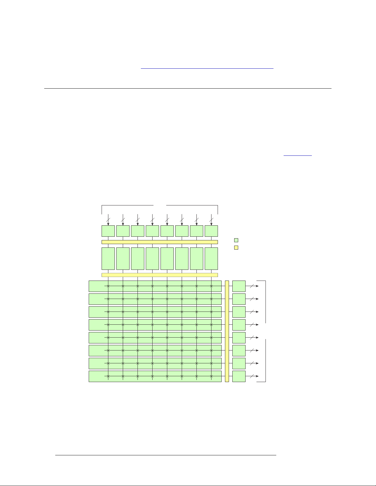
Figure 2-2 shows the basic architecture of the NV5128 switching configuration and the relationship
between the backplanes and the input cards and output cards. Backplanes house connections that
receive and distribute signals to and from the router. For more information, see Backplanes
page 13.
Each “X” (crosspoint symbol) represents a 16 input x 16 output crosspoint array. Taken together,
eight crosspoints create a 128 input x 16 output crosspoint array. This unique architecture creates a
fully non-blocking matrix such that an input can be switched to any output, and one input to one
output, or one input to many outputs.
116 173 2 3348 4964 6580 8196 97112 113128
16 16 16 16 16 16 16 16
on page 67.
on
Inputs
Slot 5 Slot 12Slot 6 Slot 7 Slot 8 Slot 9 Slot 10 Slot 11
Slot 5
Slot 1 Slot 1
Slot 2
Slot 3
Slot 4
Slot 13
Slot 14
Slot 15
Slot 16
Output Matrix Modules
Slot 12Slot 6 Slot 7 Slot 8 Slot 9 Slot 10 Slot 11
Input Backplanes
Modules
Motherboard
Input Matrix Modules
16
16
Slot 2
16
Slot 3
16
Slot 4
16
Slot 13
16
Slot 14
16
Slot 15
16
Slot 16
Output Backplanes
Outputs
Figure 2-2. NV5128 Crosspoint Architecture
In general, input cards and output cards follow the 16 inputs x 16 outputs architecture, with one
router card slot per card. There are three exceptions: Classic SWB card sets, Standard SWB cards
and machine control card sets. Each card set switching configuration is discussed in the proceeding
sections.
8 Rev 2.5 • 24 Sep 09
Page 19

2. Introduction
Module Slots and Rear Connectors
Classic SWB Switching Configurations
The Classic SWB card set is composed of two cards connected together that occupy two card slots.
The card set has a 16 input x 16 output crosspoint array. A single Classic SWB card set can be used
to create a 16 input x 16 output switching matrix, or a pair of card sets can be coupled together to
create a 32 input x 32 output matrix. The 32 input x 32 output configuration feeds the 16 inputs
from one Classic SWB card set to the second Classic SWB card set and vice versa.
When creating a 32 input x 32 output matrix, the Classic SWB cards must be installed in specific
router slots. For installation instructions, see Installing Classic SWB Backplanes
more information about the card architecture, see Classic SWB
on page 28.
on page 41. For
Standard SWB Switching Configurations
There are two types of Standard SWB output cards: a main card with a “wing” and optional expansion cards that mate with the wing on the main card. The output cards occupy four contiguous slots.
By installing the main card and up to three expansion cards, different crosspoint matrices can be
created. Because the main output card receives all 128 SWB inputs, switching configurations can
start at 16 inputs x 16 outputs, increasing in increments of 16 up to 128 inputs by 64 outputs. A second set of Standard SWB main output cards and expansion output cards can be installed, increasing
the switching configuration to 128 inputs x 128 outputs.
The Standard SWB cards must be installed in specific router slots. For installation instructions, see
Installing Other Video, Audio and Time-Code Backplanes
card architecture, see Standard SWB
Machine Control Switching Configurations
The machine control card set is composed of two cards connected together that occupy two card
slots. The machine control card set is bidirectional; it carries signals in both directions (input and
output).
A single machine control card set can support 32 ports. If a second machine control card set is
installed and combined with the first card set, the configuration can be doubled to 64 ports.
The Machine Control cards must be installed in specific router slots. For installation instructions,
see Installing Machine Control Backplanes
tecture, see Machine Control Signals
on page 28.
on page 31.
Module Slots and Rear Connectors
The NV5128 has slots for input cards, output cards, and control cards. Cards are installed through
the front of the frame for easy access and are “hot swappable”. The rear of the router is a back plate
into which backplanes housing connectors for receiving and distributing signals are installed. The
back plate also contains connections to system functions, such as a router control system, alarms or
reference signals.
on page 43. For more information about
on page 42. For more information about the card archi-
Active circuitry is contained mainly on the input cards, output cards, control cards, power supply
modules, and fan tray installed through the router’s front. However, some active circuitry for SD
and HD signals are located on the associated backplanes, which are installed through the router’s
rear. All cards and backplanes are “hot-swappable.”
NV5128 Multi-Format Router • User’s Guide 9
Page 20

2. Introduction
Module Slots and Rear Connectors
An internal motherboard spans the frame and interconnects front and rear modules, and distributes
control signals, timing information, and power. Cards, power supply modules, and the fan tray plug
into the motherboard from the front of the router and backplanes plug into the same motherboard
from the rear. Each input card and output card has a corresponding backplane. For more information on each type of card, see Active Cards
Backplanes
on page 13.
Front Slots
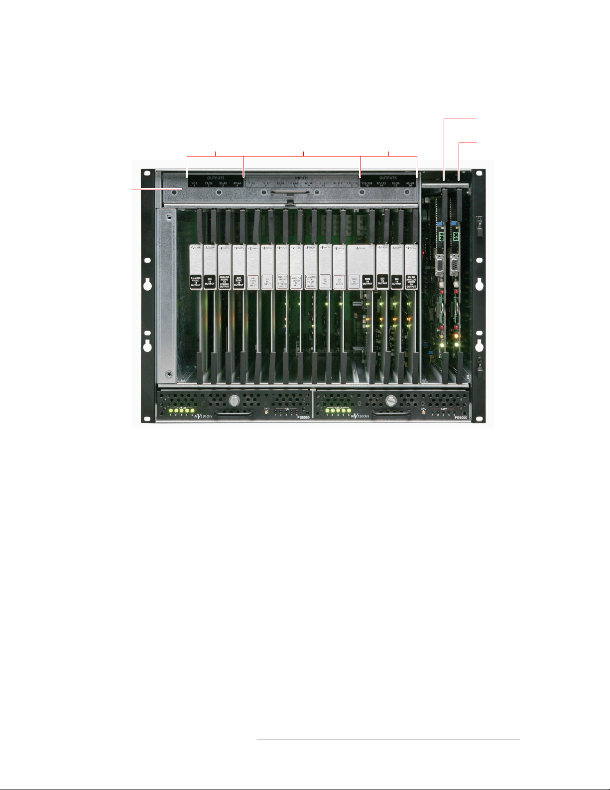
Figure 2-3, next page, shows the front of the NV5128 with the door removed. In the center of the
router are eight slots designated for input cards. To the right and left of the input slots are four slots
designated for output cards. On the far right, two slots house the primary and secondary control
cards. A fan tray is located at the top of the router chassis.
Viewing the frame from the front, slots are numbered 1 through 16, from left to right. (See
Figure 2-3.)
Each slot supports 16 channels, as follows:
• Slots 1 through 4 (for outputs): Slot 1 switches output channels 1 to 16, slot 2 switches output
channels 17-32, and so on.
on page 21. For more information on backplanes, see
• Slots 5 through 12 (for inputs) receives and process inputs 1to 128 respectively, in groups of 16
channels per slot, in ascending order, left to right, viewed from the front of the frame.
• Slots 13 through 16 (for outputs) are similar in function to slots 1 to 4, except that the output
channels are in reverse order. That is, slot 13 switches output channels 113 to 128, slot 14
switches 97 to 112, slot 15 switches 81 to 96 and slot 16 switches 65 to 80. The reverse order of
the output channels in the right-hand side of the frame is intentional; it makes it easier to obtain
equal path lengths on the frame’s motherboard, facilitates analog video timing, and facilitates
the use of Classic SWB card sets and machine control card sets installed in slots 11 to 14 (see
Installing Active Cards
on page 44).
10 Rev 2.5 • 24 Sep 09
Page 21
S
Pullout
Fan Tray
2. Introduction
Module Slots and Rear Connectors
Figure 2-3 shows the location of the input card, output cards, and control card slots, as viewed from
the front.
econdary
Slots 1–4
(Outputs 1–64)
Slots 5–12
(Inputs 1–128)
Slots 13–16
(Outputs 128–65)
Control Card
Primary
Control Card
Main PS6000 Power Supply Redundant PS6000 Power Supply
Figure 2-3. NV5128 Frame with Modules (Front View)
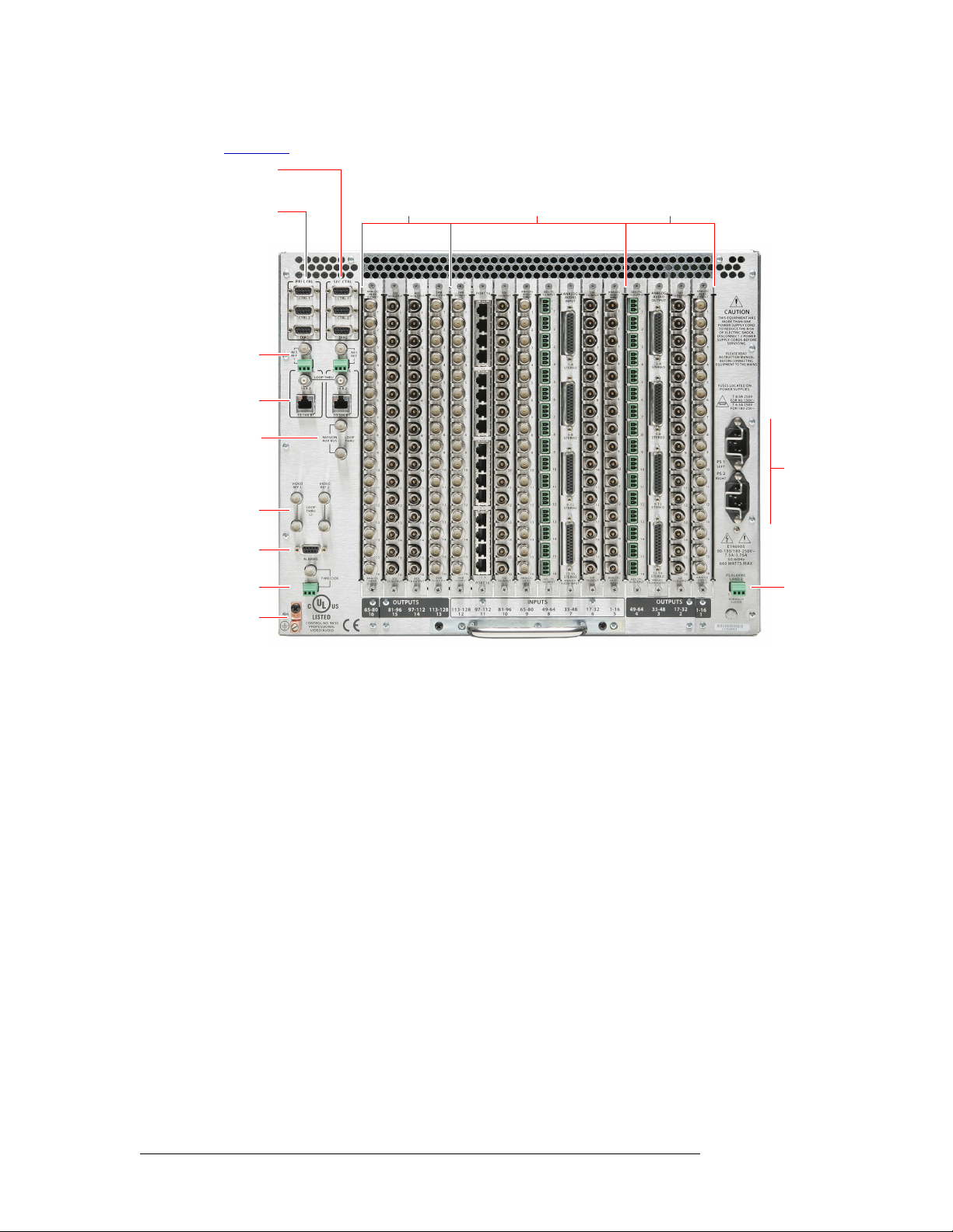
Rear Connections
The rear of the NV5128 (Figure 2-4) features a back plate containing backplanes for receiving and
distributing signals. Backplanes plug into connectors located on the motherboard, which runs the
width of the frame. In the left-hand region are connections for system functions, as shown in
Figure 2-7 on page 16. Two AC power connections are located in the right-hand region.
NV5128 Multi-Format Router • User’s Guide 11
Page 22
2. Introduction
Module Slots and Rear Connectors
Figure 2-4 shows the router with backplanes installed on the rear of the NV5128 frame.
Secondary
Control
Primary
Control
AES Ref.
Ethernet
AUX.
Bus
Video Ref.
Backplanes
Output 65–128 Input 128–1 Output 64–1
Power
Connections
System
Alarm
Time Code Ref.
Ground Lug
Figure 2-4. NV5128 Frame with Backplanes (Rear View)
Power Supply
Alarm
12 Rev 2.5 • 24 Sep 09
Page 23
2. Introduction
Module Slots and Rear Connectors
Backplanes
The NV5128 features rear backplanes that can be inter-mixed in a single router frame, as shown in
Figure 2-4 on page 12.
DB25
Connectors
ANALOG
AUDIO
INPUT
1-4
STEREO
5-8
STEREO
9-12
STEREO
13-16
STEREO
ANALOG
AUDIO INPUT
Phoenix
Connectors
AES / TC
16 INPUT
+
S
1
2
3
4
5
6
7
8
9
10
11
12
13
14
15
16
AES/ TC
INPUT
RJ_45
Connectors
PORT 16
1-4
5-8
9-12
13-16
PORT 16
BNC
Connectors
SDI
OUTPUT
1
2
3
4
5
6
7
8
9
10
11
12
13
14
15
16
SDI
OUTPUT
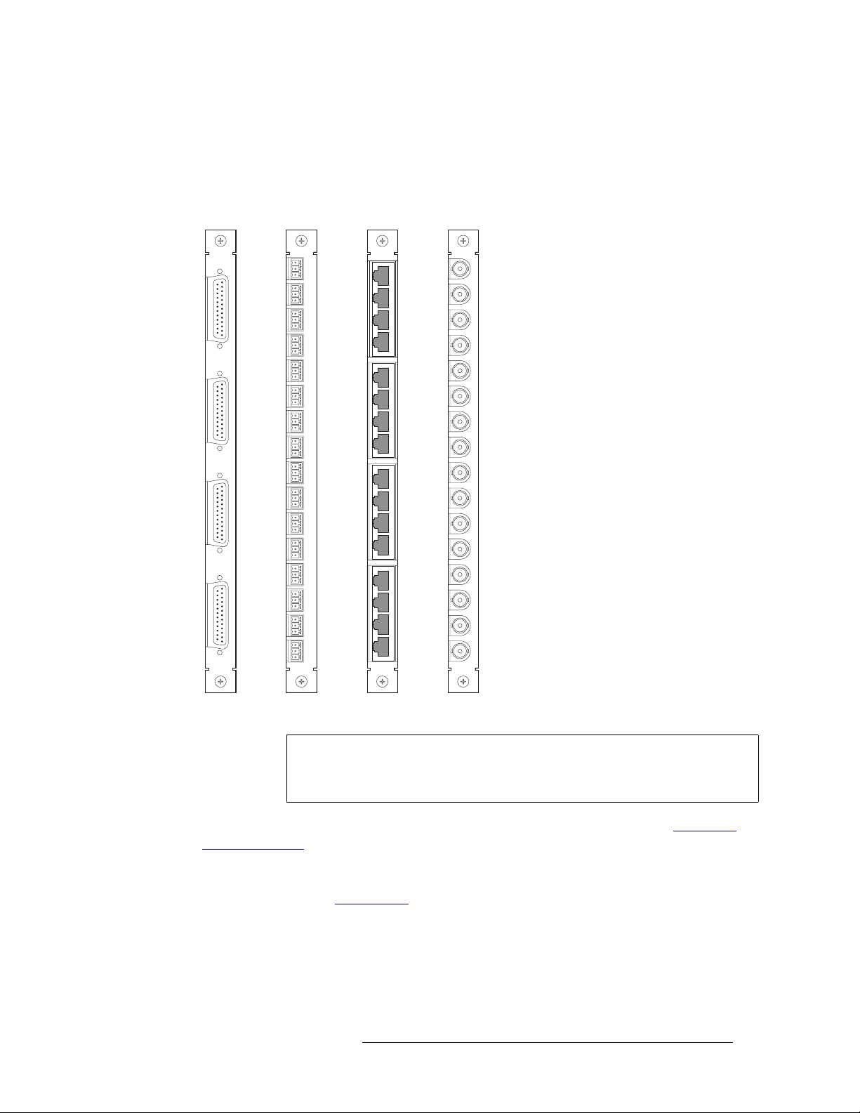
Each backplane contains connectors for
receiving or distributing signals. The
number of connectors on a backplane
and the type of connector is determined
by the type of signal. Figure 2-5 shows
the four types of connectors available on
backplanes.
There are five types of backplanes. All
backplanes are passive unless otherwise
noted:
• DB25 connectors
— Used for analog
audio signals.
• Phoenix connectors
— Used for AES
balanced signals and SMPTE longitudinal time code signals.
• RJ45 connectors
— Used for machine
control signals.
• BNC connectors
— Used for analog
video and AES unbalanced audio signals.
• BNC connectors (active)
— Used for
incoming and outgoing SWB signals
and for incoming SD signals.
Figure 2-5. Backplanes
Important The two backplanes containing BNC connectors are not interchangeable. The
BNC backplane for SD and SWB signals are active and can not be used for analog video or AES audio signals.
The type of signal being received or distributed determines the backplane used (see Backplane
Types and Signals on page 14). For each backplane installed a corresponding input card or output
card must also be installed. For example, if a backplane is installed to receive AES unbalanced signals, then the input card capable of routing AES unbalanced signals must be installed in the corresponding card slot (see Active Cards
on page 21).
Video Backplanes
Unlike other backplanes, the backplanes for incoming and outgoing SWB signals and incoming SD
signals have active components. These backplanes cannot be used with analog video cards.
NV5128 Multi-Format Router • User’s Guide 13
Page 24
2. Introduction
Module Slots and Rear Connectors
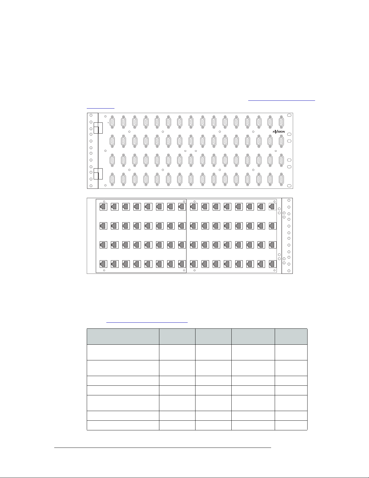
Machine Control Breakout Panel
The backplane module for machine control signals has 16 RJ-45 connectors. Miranda offers an
optional machine control breakout panel (BP2-PORT-64) that can be used with up four machine
control backplane modules. The panel has 64 RJ-45 connectors on one side and 64 DE9 (female)
connectors on the other, as shown in Figure 2-6. The DE9 connector wiring follows SMPTEdefined pin assignment standards. For installation instructions, see Installing Machine Control
Backplanes on page 42.
2345678910111213
MACHINE CONTROL
BREAKOUT PANEL
17 18 19 20 21 22 23 24 25 26 27 28 29
33 34 35 36 37 38 39 40 41 42 43 44 45
49 50 51 52 53 54 55 56 57 58 59 60 61
BP-PORT-64
14 15 16
30 31 32
46 47 48
62 63 64
Front View
Rear View
Figure 2-6. Optional Machine Control Breakout Panel
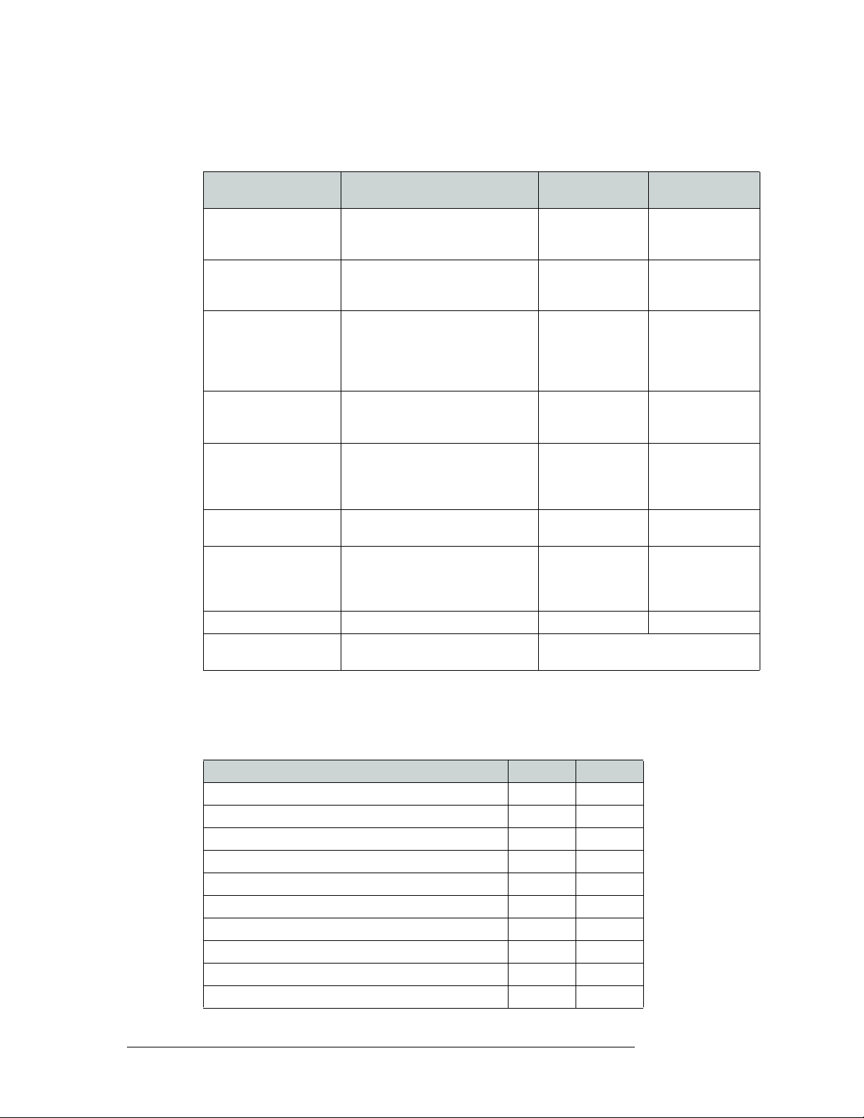
Backplane Types and Signals
The following is a list of each backplane type, associated connectors, signal types managed, and the
number of signals each backplane can receive or distribute. For the part number for each backplane
list, see Cards, Card Sets, and Backplanes
on page 93.
Signal Types
Backplane
Name
Connector
Type
Connectors per
Backplane
Signals
Managed
AES unbalanced, synchronous AES BNC 16 16 stereo or
32 mono
AES balanced, synchronous AES/TC Phoenix 16 16 stereo or
32 mono
AES unbalanced, asynchronous AES BNC 16 16 stereo
AES balanced, asynchronous AES/TC Phoenix 16 16 stereo
Analog audio Analog audio DB25 4 16 stereo or
32 mono
Digital Video, SD SDI BNC 16 16
Digital Video, SWB SWB BNC 16 16
14 Rev 2.5 • 24 Sep 09
Page 25

2. Introduction
Module Slots and Rear Connectors
Backplane
Signal Types
Analog Video Analog video BNC 16 16
Time Code AES/TC Phoenix 16 16
Machine Control PORT 16 RJ-45 16 16
Name
Connector
Type
Connectors per
Backplane
Signals
Managed
The BP2-Port-64 panel has 64 RJ-45 connectors on one side and DE9 (female) connectors on the
other side. It allows you to use DE9 cables to connect machine control ports to devices.
NV5128 Multi-Format Router • User’s Guide 15
Page 26
2. Introduction
Module Slots and Rear Connectors
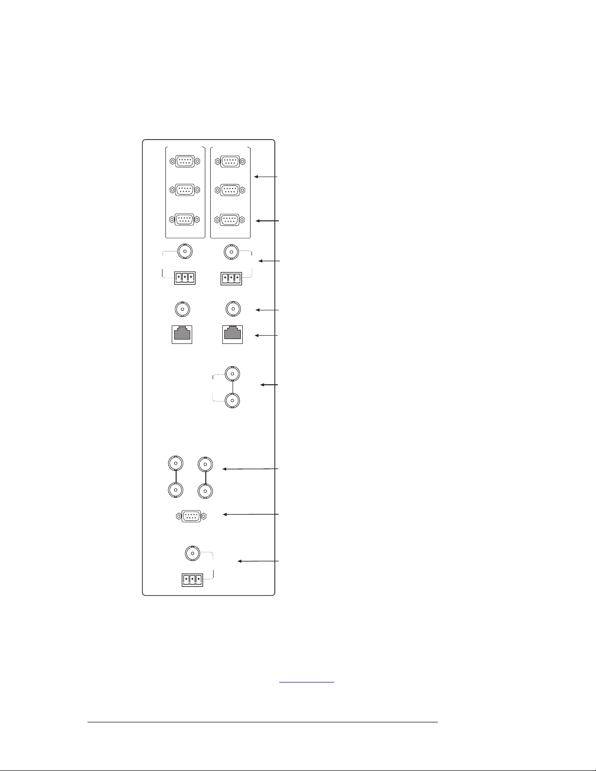
System Connections
The NV5128 features connections for managing system functions. System connections are located
on the left side of the frame when facing the rear of the router.
AES
REF1
PRI CTRL
10/100 B T
PRI CTRL
CTRL 1
CTRL 2
DIAG
10 B 2
SEC CTRL
SEC CTRL
NODE
BUS
CTRL 1
CTRL 2
DIAG
10 B 2
10/100 B T
AES
REF2
LOOP
THRU
Serial Connections
to Control System
Diagnostic
Connections
AES
Reference
Frame Expansion
(Not supported)
Ethernet
Connections
to Control
System
AUX Bus
Connection
to Control System
These connections are used to connect to:
• A router control system using either
serial, Ethernet or GSC Node Bus connectors.
• A stable source of audio and/or video
signal for reference purposes.
• The UniConfig application, installed
on a configuration PC.
• A system alarm that sends notification
of a system failure, such as a fan malfunction.
• A power supply alarm that sends notification of a power supply failure.
Figure 2-7 shows the system connections
located on the rear of the router. Each system connection and function is described
in the proceeding sections.
VIDEO
REF 1
Figure 2-7. System Connections (Rear View)
LOOP
THRU
(2)
ALARMS
VIDEO
REF 2
TIME CODE
Video Ref
Connections
System Alarm
Connection
Time Code
Reference
(Not supported)
Router Control System Connections
A router control system is used to manage routing configurations in the router. The router control
system sends instructions to the control card, which in turn sends commands directing signal
switching within in the router. (See Control Cards
rate external unit, which is connected to the router. The NV5128 provides three types of a router
16 Rev 2.5 • 24 Sep 09
on page 21.) A router control system is a sepa-
Page 27
2. Introduction
Module Slots and Rear Connectors
control system connections: serial, Ethernet or GSC Node Bus. The router control system determines which connection is used. For example, to connect to the NV9000 router control system an
Ethernet connection is preferred.
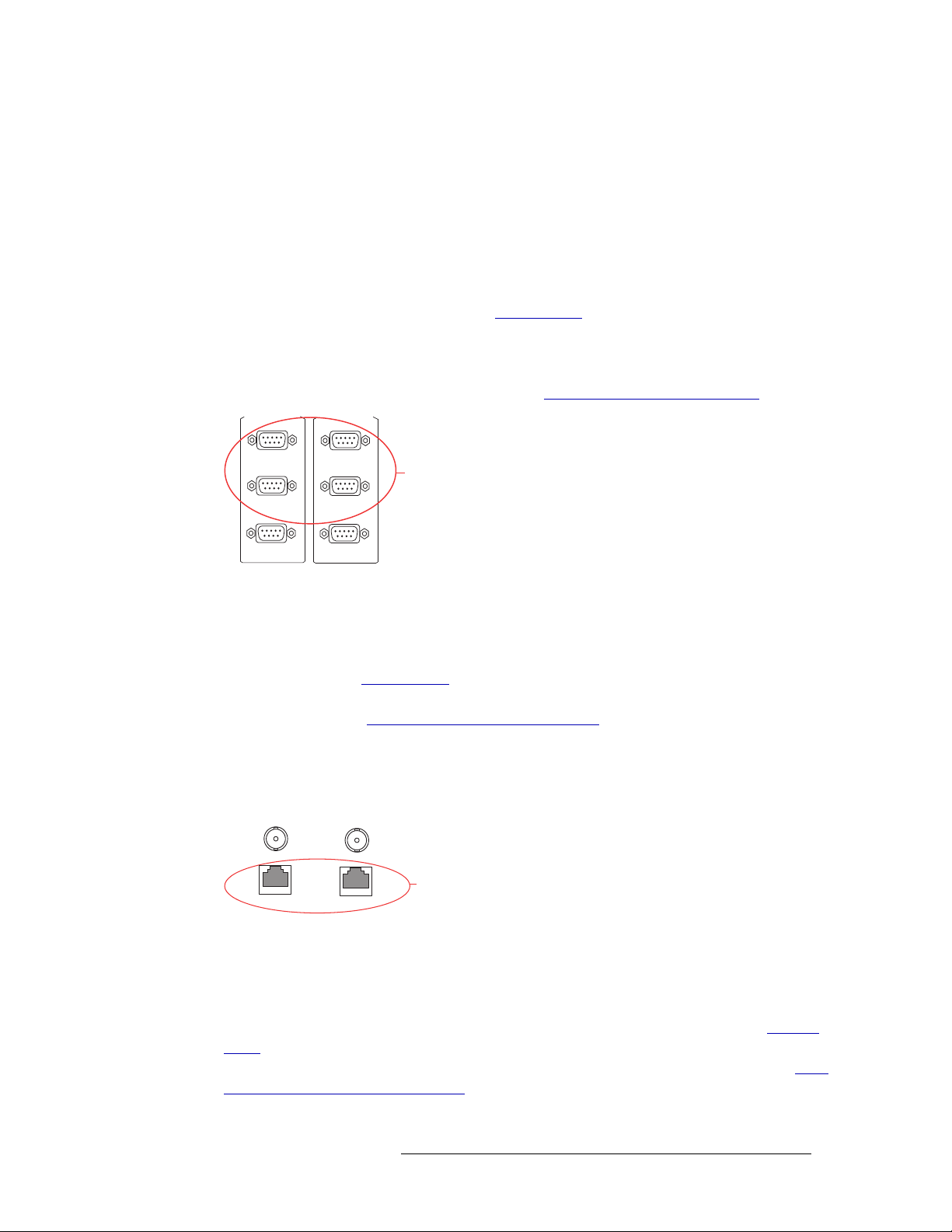
Serial Connections
The NV5128 has four serial router control system connections, as shown in Figure 2-8. The connections are divided into two sets, one primary (‘PRI CTRL’) and one secondary (‘SEC CTRL’).
Primary control connects to the primary control card. Secondary control connects to the secondary
(optional for redundancy) control card (see Control Cards
into connections that correspond to router control systems: ‘CTRL 1’ corresponds to the primary
control system and ‘CTRL 2’ corresponds to a redundant router control system. Using ‘CTRL 2’
connections, you can connect to an alternate control system (i.e., backup system) or set up dual
control, if desired. For installation instructions, see Serial Router Control Connections
PRI CTRL
SEC CTRL
on page 21). Each set is further divided
on page 59.
CTRL 1
CTRL 2
DIAG
Figure 2-8. Serial Connections to Router Control System (Rear View)
CTRL 1
CTRL 2
DIAG
Serial Connections
to Control System
Ethernet Connections
The NV5128 has two Ethernet router control system connections, labeled ‘10/100 BASE T’, as
shown in Figure 2-9. Both connections are shared by both the primary control card and the secondary control card. (See Control Cards
on page 21.) Because Ethernet network connections can be
used to connect to alternate control systems, there are no separate connections provided. For installation instructions, see Ethernet Router Control Connections
on page 61.
In order for the router to communicate with the router control system through an Ethernet connection, an IP address for the router needs to be set in the control card. The IP address is set using UniConfig. For more information, see the UniConfig User’s Guide.
COMMON
TO
PRI & SEC
10 BASE 2
10/100 BASE T
Figure 2-9. Ethernet Connections to Router Control System (Rear View)
10 BASE 2
10/100 BASE T
Ethernet
Connections
to Control
System
GSC Node Bus Connections
Some third-party router control systems require a GSC Node Bus connection. The NV5128 has one
GSC Node Bus connection, labeled ‘NODE BUS’, as shown in Figure 2-10, next page. The connection is shared by both the primary control card and the secondary control card. (See Control
Cards on page 21.) To use the GSC Node Bus connection, an optional module must be installed on
each control card being used. For details, contact Miranda. For installation instructions, see GSC
Node Bus Router Control Connections on page 61.
NV5128 Multi-Format Router • User’s Guide 17
Page 28
2. Introduction
Module Slots and Rear Connectors
NODE
BUS
Figure 2-10. GSC Node Bus Connections to Router Control System (Rear View)
LOOP
THRU
GSC Node Bus
Connection
to Control System
Control System Expansion Connections
The NV5128 has two connections for the router control system when connecting multiple router
frames together, labeled ‘10 B 2’, as shown in Figure 2-11. However, frame expansion is not supported in the NV5128 and these connections are inactive.
Control System
Expansion
10 B 2
10/100 B T
Figure 2-11. Control System Expansion Connection (Rear View)
10 B 2
10/100 B T
Connection
Diagnostic Connections
The diagnostic connections enable the NV5128 to communicate with the UniConfig application.
UniConfig runs on external hardware (e.g., PC) separate from the router and is used to perform system setup tasks, and configure and monitor the router. (See Configuration
information on UniConfig, see the UniConfig User’s Guide.
There are two types of diagnostic connections: temporary and permanent. A temporary diagnostic
serial connection is located on the front of each control card. (See Control Cards
manent diagnostic connections are located on the rear of the router, labeled ‘DIAG’, as shown in
Figure 2-12 on page 18. Miranda recommends using the temporary diagnostic connection when
reconfiguring the router because the port has fixed communications parameters. The permanent
diagnostic connections are used for upgrading firmware or control card protocols when there is no
Ethernet connection to the router. For instructions on making temporary or permanent diagnostic
connections, see Permanently Connecting to UniConfig
on page 63.
on page 67.) For more
on page 21.) Per-
There are two permanent ‘DIAG’ ports, one primary (‘PRI CTRL’) and one secondary (‘SEC
CTRL’). The primary control connects to the primary control card. The secondary control connects
to the secondary (optional for redundancy) control card.
PRI CTRL
CTRL 1
CTRL 2
DIAG
Figure 2-12. Permanent Diagnostic Connections (Rear View)
SEC CTRL
CTRL 1
CTRL 2
DIAG
Diagnostic
Connections
AES Reference Connections
The AES reference is used for clock generation, which provides a timing reference for AES synchronous signals and for timing circuits on the control card. Certain signals require an AES refer-
18 Rev 2.5 • 24 Sep 09
Page 29

2. Introduction
Module Slots and Rear Connectors
ence. (See Using Video and Audio References on page 6.) For optimum audio output, signals must
be clock-locked to the same reference. Input impedance is selected by setting jumpers on the control card. (See Control Card Jumper Settings
The NV5128 has two AES reference connections labeled ‘AES REF1’ and ‘AES REF2’, as shown
in Figure 2-13. Both connections are shared by the primary control card and the secondary control
card. (See Control Cards
on page 21.) The AES reference connections are “redundant” and use the
same reference type. When both reference connections are connected, if one reference fails, the
control card automatically fails-over to the redundant reference.
Synchronous AES input cards can work with inputs that are not locked to a common AES reference. These inputs are treated as non-synchronous AES signals. Although possible, this is not recommended for high-quality program audio feeds because the audible effects may be unpredictable,
depending on the program content and the degree of offset in the incoming data rate.
on page 68.)
An AES reference is required when using synchronous AES output cards. (See AES Synchronous
on page 23.) While it is possible to let the clock generator on the control card free-run, the synchronous AES outputs may contain ticks and pops, the severity of which depends on the difference in
clock rate.
The AES reference connection requires a stable signal source of AES with a sample rate of 48kHz.
For instructions on making AES reference connections, see AES Reference
AES
REF1
Figure 2-13. Connections to AES References (Rear View)
AES
REF 2
AES
Reference
on page 57.
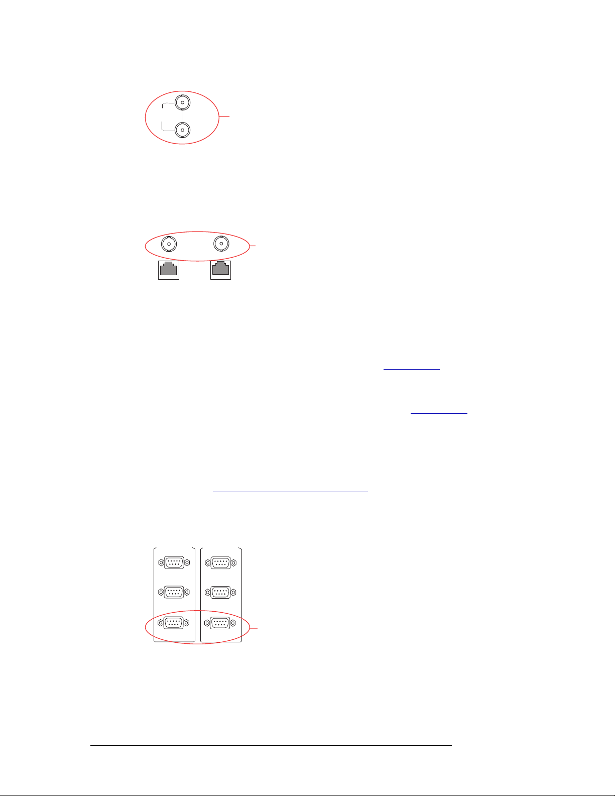
Video Reference Connections
The NV5128 provides timing reference connections for video signals, labeled ‘VIDEO REF 1’ and
‘VIDEO REF 2’, as shown in Figure 2-14 on page 20. These connections provide a reference input
for determining the router’s video frame switch point and are required for certain signals. (See
Using Video and Audio References
tions or a different reference used for each connection. For more information, see Redundant and
Dual References on page 19.
If a video reference is present, signals switch at the defined frame and line switch points. If a video
reference is not present, the router still switches the signal, but to an internal reference. When the
video reference is not connected the control card red LEDs remain lit. (See Indicator LEDs
page 76.)
on page 6.) The same reference can be used for both connec-
on
The video reference connections require a stable source of PAL, NTSC or Tri-level sync. For
instructions on making video reference connections, see Video Reference
on page 58.
Redundant and Dual References
There are two video reference connections. The same reference can be used for both connections or
a different reference for each connection. When using the same, or “redundant,” references for both
connections, if one reference fails, the control card automatically fails-over to the redundant reference. When using different references, or “dual” references, routing switch takes can be configured
NV5128 Multi-Format Router • User’s Guide 19
Page 30

2. Introduction
Module Slots and Rear Connectors
to occur based on one or the other reference. For example, ‘VIDEO REF 1’ uses NTSC as a reference and ‘VIDEO REF 2’ uses PAL as a reference.
“Redundant” or “dual” mode is selected using UniConfig. If “dual” is selected, each output can be
configured individually to use ‘VIDEO REF 1’ or ‘VIDEO REF 2’ as the reference. For more
information, see the UniConfig User’s Guide.
VIDEO
REF 1
Figure 2-14. Connections to Video References (Rear View)
LOOP
THRU
VIDEO
REF 2
Video Ref
Connections
Alarm Connections
The NV5128 provides a system alarm that notifies you of a malfunction, such as when a fan or
power supply is not functioning properly. The alarm connection can be connected to external equipment that display visual signals when an alarm is activated. Creation of external monitoring equipment is outside the scope of this manual. However, basic instructions on wiring the alarm
connections for external monitoring is provided. See Making Alarm Connections
In addition to an alarm connection, the router control system receives status information from the
router’s control card(s). The control cards read the status of the router’s power supply and fans
through the ‘Power Supply Alarm’ connection. The information is then communicated to the router
control system and is viewable using UniConfig. For more information, see the UniConfig User’s
Guide.
A SNMP agent can be installed on the router control system (i.e., NV9000) to communicate power
supply information to a SNMP manager. Installation of SNMP agents and use of SNMP managers
is outside the scope of this User’s Guide.
on page 64.
The router alarm connection is labeled ‘ALARM’, as shown in Figure 2-15
making alarm connections, see Making Alarm Connections
System Alarm
ALARMS
Figure 2-15. Alarms Connection (Rear View)
Connection
on page 64.
. For instructions on
Time Code Reference Connections
The NV5128 has connections for a reference source for Time Code signals labeled ‘TIME CODE’,
as shown in Figure 2-16. However, time code references are not support at this time.
TIME CODE
Figure 2-16. Time Code Reference Connection (Rear View)
20 Rev 2.5 • 24 Sep 09
Time Code
Reference
Connection
Page 31

Active Cards
The NV5128 features several active cards that manage incoming signals, forward commands from
the router control system, perform signal switching, and distribute outgoing signals. Each card
slides into a card guide and has two levers that aid card insertion and ejection.
There are:
Each input card and output card supports a specific signal type and has a corresponding backplane.
(See Signals Types and Rates
Card functions are described in the proceeding sections. For information on installing cards, see
Installing Active Cards
Control Cards
2. Introduction
Active Cards
• Two control cards (one primary, one secondary; optional for redundancy).
• Up to 8 input cards.
• Up to 8 output cards.
on page 5 and Backplanes on page 13.)
on page 44.
The router has two control cards (EM0374), one primary and one secondary (optional for redundancy). A control card receives commands from the router control system, and in turn, controls the
input and output cards. In addition, the control card manages reference signals, supplies appropriate
timing and control signals to the input cards and output cards, and sends alarm signals to the router
control system.
Both the primary control card and the secondary control card receive router control system commands, but only the primary control card actively sends commands to the output cards. Because
both cards receive router control system commands, if the active (primary) control card fails, the
back-up (secondary) control card automatically takes over processing without interruption. In addition, the primary control card and secondary control card communicate with each other. Should
either control card fail, the now active control card communicates the failure to the router control
system.
There are several jumpers on the control card which must be configured before putting the router
into service. For more information, see Control Card Jumper Settings
The control card receives power from the motherboard and includes a status reporting circuit. Four
LEDs on the front of the control card indicate the card’s status: low battery (Red), alarm (Red),
active (Amber), and operating normally (Green). For more information, see Indicator LEDs
page 76.
on page 68.
on
Systems Clock Generator Card
The systems clock is located on the control card. (See Control Cards on page 21.) This clock is critical and used by all input cards and output cards; if the clock fails, the router cannot route audio signals. As a preventive measure, a secondary control card (optional for redundancy) can be installed
to act as a backup should the primary control card fail. If you do not want to install two control
cards, an optional Systems Clock Generator card (EM0414) can be installed in place of the secondary control card. The Systems Clock Generator card ensures that in the event of a primary control
card failure the system continues to receive clock information. However, the Systems Clock Generator card only provides clock information and cannot take over control card tasks.
NV5128 Multi-Format Router • User’s Guide 21
Page 32

2. Introduction
Active Cards
Audio I/O Cards
Audio input cards and output cards support AES synchronous, AES asynchronous, and analog
audio signals. Each type of signal requires a unique type of card. For example, to support AES synchronous signals, cards that specifically manage AES synchronous signals must be installed. Different types of audio input cards and output cards can be inter-mixed in a single frame to meet
specific switching configuration needs.
For each input card and output card installed, an associated backplane must also be installed. For
more information, see Backplanes
Analog and AES synchronous signals may be converted between analog and digital within the
NV5128 router frame. (See Mixing Analog and Digital
chronous signals may be routed as stereo or mono signals, but not as AES asynchronous signals.
AES asynchronous signals can only be routed as stereo signals. However, using the SRC input
card, asynchronous AES signals can be converted to synchronous signals and then routed as stereo
or mono signals. (See AES Sample Rate Converter (Input Only)
The following is a list of the different audio input cards and output cards available. Each card is
listed by the type of signal it manages. For your convenience, the part number for each card has
been included.
on page 13.
on page 7.) In addition, analog or AES syn-
on page 24.)
Input Card/Output Card
AES synchronous balanced and
unbalanced
AES asynchronous balanced
and unbalanced
Inputs and
Outputs
16 stereo or 32
mono
16 stereo 16 stereo at 32
Incoming Signals
per Sample Rate
16 stereo (32 mono) at
48
kHz
kHz to
96 kHz (passed
Input Card Part
Number
EM0389 EM0390
EM0387 EM0388
Output Card
Part Number
through)
AES Sample Rate Converter 16 stereo 16 stereo (32 mono) at
22
kHz to 108 kHz
asynchronous,
EM0500
(input only)
N/A
converted to
synchronous AES
Analog 16 stereo or 32
mono
locked to 48
16 stereo (rate N/A) or
32 mono (rate N/A).
Converts analog input to
internal digital format
locked to
kHz
EM0585 EM0586
48 kHz
For a list of all audio input cards and output cards and their associated backplanes, see Cards, Card
Sets, and Backplanes on page 93.
Card Power and Fuses
Analog audio and AES input cards and output cards receive power from the motherboard. Each
card uses direct current converters (DC/DC) to convert the corresponding backplane’s +48
into the appropriate regulated supply voltage(s). The combination of pre-regulators and DC/DC
converters and supply voltages varies from card type to card type, depending on the requirements
of the associated circuitry. There is a non-serviceable, self-resetting 1A fuse located on each card.
For more information, see Fuse Replacement
on page 76.
VDC
22 Rev 2.5 • 24 Sep 09
Page 33

2. Introduction
Active Cards
Status Reporting
All audio input cards and output cards feature a circuit that performs status reporting and drives the
card’s functions. Two LEDs on the front of the card indicate the card’s status: alarm (Red), power
good (Green). Unique to the analog input card, three additional LEDs situated further back on the
card indicate if software is loaded (Amber), and if there is good communication with the control
card (Green) or bad communication with the control card (Red). For more information, see Indica-
tor LEDs on page 76.
The functions of each type of card are described in the proceeding sections. Cards are listed by the
signal type supported.
AES Synchronous
Incoming and outgoing AES synchronous signals, balanced or unbalanced, are received or distributed through passive connectors housed on backplanes: 16 BNC connectors for unbalanced signals
or 16 Phoenix connectors for balanced signals. (See Backplanes
Input Card
The AES synchronous input (EM0389) receives up to 16 stereo signals through passive backplane
I/O connectors. Each signal is routed as an AES signal and is transformer coupled and forwarded to
a receiver. At that time, the signal is synchronized to the system clock; adding and dropping samples as needed until the signal is synchronized.
on page 13.)
The receiver forwards the signal to a buffer, which in turns sends the signal to the motherboard and
onward to output cards for switching.
Note Near-synchronous operation may cause minor disturbances in the audio signal.
These effects are usually masked by the program audio, depending on the sample
rate offset or magnitude and timing of the disturbance.
Output Card
The AES synchronous output card (EM0390) receives up to 128 stereo inputs from the motherboard. The signals are sent to receivers and then to a crosspoint array (128 inputs x 16 outputs stereo; 256 inputs x 32 outputs mono) for switching. The crosspoint splits the AES signal into a right
channel, a left channel, and channel status bits for switching as mono signals. Each mono channel
is then recombined with another mono channel to create a new AES signal. The outgoing AES signals are switched synchronously and sent to drivers and backplane I/O connectors for distribution.
Figure 2-17 shows the synchronous AES signal path.
Output Card
XPT
128x16 stereo
256x32 mono
I/O
Connectors
I/O
(up to 16)
Connectors
Transformer
Coupled
Input Card
Recr
Recr
Motherboard
(up to 16)
Figure 2-17. Synchronous AES Signal Flow (Balanced or Unbalanced)
NV5128 Multi-Format Router • User’s Guide 23
Page 34

2. Introduction
Active Cards
AES Asynchronous
Incoming and outgoing AES asynchronous signals are received or distributed through passive connectors housed on backplanes: 16 BNC connectors for unbalanced signals or 16 Phoenix connectors for balanced signals. (See Backplanes
routed only to asynchronous AES output cards; they cannot be routed to analog or AES synchronous output cards, nor can they be routed as mono channels.
Asynchronous AES operation is not intended for use with “live” or program audio feeds where
glitches at switch boundaries are unacceptable. Instead, asynchronous input cards and output cards
provide an economical way to select AES signal sources, even ones that are synchronous, for ongoing operations such as editing, monitoring or dubbing.
Input Card
The AES asynchronous input card (EM0387) receives up to 16 stereo signals through backplane
I/O connectors. The architecture of the input card is identical to that of the AES synchronous input
card, except that signals are not synchronized to the systems clock on the control card. (See AES
Synchronous on page 23.)
Output Card
The AES asynchronous output card (EM0388) receives up to 128 stereo inputs from the motherboard. The signals are then sent to a crosspoint array (128 inputs x 16 outputs) for switching. The
outgoing AES signals are switched asynchronously (i.e., not synchronous with a system clock) and
then sent to balanced output drivers and backplane I/O connectors for distribution. Be aware that
this may cause possible problems in the output signal stream.
on page 13.) Asynchronous AES input signals can be
Figure 2-18 shows the asynchronous AES signal path.
Input Card
I/O
Figure 2-18. Asynchronous AES Signal Flow (Balanced or Unbalanced)
Transformer
(up to 16)
Connectors
Coupled
Recr
Motherboard
Recr
Output Card
XPT
128x16 stereo
I/O
Connectors
AES Sample Rate Converter (Input Only)
The AES Sample Rate Converter (SRC) input card (EM0500) provides additional routing flexibility. The card accepts up to 16 asynchronous AES inputs with a wide range of sample rates. The signals are converted into synchronous AES signals locked to the 48
before being forwarded to the motherboard. This means that a wide variety of AES-compatible digital audio inputs with sample rates from 22
kHz to 108 kHz can be integrated into a synchronous
AES environment or converted to analog audio outputs as desired.
The receivers buffer the input, extracting audio data, sample clock, and applicable channel status
information. The clock and data signals are then processed by an asynchronous SRC and the rateconverted data reformatted and combined with the appropriate channel status information and user
bits. Reference clock signals from the control card are used to synchronize the data to create an
AES format signal. The signal is then forwarded to the motherboard for distribution to output cards.
kHz AES reference (page 18)
(up to 16)
24 Rev 2.5 • 24 Sep 09
Page 35

Figure 2-19 shows the signal path through the SRC.
Input Card
2. Introduction
Active Cards
I/O
Figure 2-19. Signal Flow through SRC Card
Transformer
(up to 16)
Connectors
Card
Control
Coupled
Reference Clock Signal
AES
Recr
Channel Status Bits
SRC
Timing
Control and
AES3
Encoder
I/O
Motherboard
Connectors
(up to 16)
Analog Audio
Incoming and outgoing analog audio signals are received or distributed through four DB25 connectors, housed on a backplane. (See Backplanes
The analog audio input card and output card feature DIP switches and a jumper that allow gain and
mute detection to be set. (See Analog Audio Switches
DIP switch set, the operating level of the card can be set to match the operating level of the facility.
By matching the incoming signal level, there is less degradation of the signal when it is converted
to digital for internal routing in the router. For information on setting analog input card levels, see
Analog Audio Switches
on page 69.
Input Card
The analog audio input card (
EM0585) receives up to 16 stereo signals (32 mono channels) through
passive backplane I/O connectors. Inputs are forwarded to an analog-to-digital (A/D) converter.
The A/D converter accepts two analog signals, either left and right channels of a stereo pair or two
mono channels. The A/D converter is rate locked to the systems clock on the control card, converting the signals to a sample rate of 48
kHz and into AES compatible bit streams containing the sam-
pled data. The audio data is set to a common sample point, which is important for proper phase
alignment of audio signals. The resulting synchronous AES signals are sent to the motherboard.
on page 13.)
on page 69.) In addition, using a separate
Output
The analog audio output card (EM0586) receives 128 stereo inputs from the motherboard. The signals are then sent to a crosspoint array of 128 inputs x 16 outputs (256 inputs x 32 outputs mono)
for switching and then on to a digital-to-analog (D/A) converter which converts the signal from
digital format to analog. From the D/A converters, the analog signals have low-pass filtering and
gain correction applied and then forwarded to output cable drivers and backplane I/O connectors
for distribution.
Note The analog audio output card is designed to function in a voltage-matched system
driving high impedance loads. The output drivers are not designed to drive 600
loads continuously and may overheat if used in a 600
NV5128 Multi-Format Router • User’s Guide 25
Ω environment.
Ω
Page 36

2. Introduction
Active Cards
Figure 2-20 shows the signal path for an analog signal.
Input Card
I/O
Figure 2-20. Simplified Analog Audio Signal Flow
Recr
(up to 16)
Connectors
A/D
Con-
verter
Recr
Motherboard
Output Card
XPT
128x16 stereo
256x32 mono
D/A
Con-
verter
I/O
Connectors
Video I/O Cards
Video input cards and output cards support the routing of SD, SWB, and analog video signals. Each
type of signal requires a unique type of card. For example, to support SWB signals, SWB input
cards and SWB output cards must be installed. Different types of input cards and output cards can
be inter-mixed in a single frame to meet specific switching configuration needs.
The output card does not need to match the signal type of the input card, but must be able to route
compatible signals. For example, if an analog video input card is installed it can be paired with an
analog video output card.
For each input card and output card installed, an associated backplane must also be installed. For
more information, see Backplanes
There are two unique sets of input cards and output cards that support SWB signals: Classic SWB
card sets and Standard SWB cards. Both types of cards receive, switch and distribute SWB signals.
The two sets of cards differ in the switching configuration each supports. The Classic SWB card set
can be used individually for a 16 inputs x 16 outputs switching configuration, or coupled with
another Classic SWB card set to create a 32 inputs x 32 outputs switching matrix. For details, see
Switching Configurations
on page 8.
on page 13.
(up to 16)
The following is a list of the different video input cards and output cards available:
Inputs and
Input Card/Output Card
Outputs
SMPTE Standard Rates
SD 16 259M, 344M < 270Mb/s EM0383 EM0384
Classic SWB 16 259M, 344M,
≤ 1.5
Gb/s EM0395 (I/O card set)
292M
Standard SWB 16 259M, 344M,
Gb/s EM0466 Standard:
≤ 1.5
292M
Analog Video 16 PAL or NTSC analog composite
video
Analog Video to SD
Converter (AVC)
16 Input: PAL or NTSC analog
composite video
Converted to: SMPTE 259M-C,
(4:2:2),
270 Mb/s
SD to Analog Video
Converter (AVC)
16 Input: SMPTE 259M-C, 270Mb/s
Converted to: PAL or NTSC
analog composite video
26 Rev 2.5 • 24 Sep 09
Input Card Part
Number
Output Card
Part Number
EM0463
Expansion:
EM0465
EM0375 EM0376
EM0432 N/A
N/A EM0433
Page 37

2. Introduction
Active Cards
Each card is listed by the type of signal it manages. For your convenience, the part number for each
card has been included. For a list of all video input cards and output cards and their associated
backplanes, see Cards, Card Sets, and Backplanes
Card Power and Fuses
Each input card and output card uses direct current converters (DC/DC) to convert the corresponding backplane’s +48
VDC into the appropriate regulated supply voltage(s). The combination of pre-
regulators and DC/DC converters and supply voltages varies from module type to module type,
depending on the requirements of the associated circuitry. There is a non-serviceable, self-resetting
1A fuse located on each module.
Status Reporting
All video input cards and output cards feature a circuit that performs status reporting and drives the
card’s functions. Two LEDs on the front of the card indicate the card’s status: alarm (Red), power
good (Green). Three additional LEDs on the output cards, situated further back on the card, indicate
the card is “healthy” (Amber) and that good communication (Green) or bad communication (Red)
exists. For more information, see Indicator LEDs
The functions of each type of card are described in the proceeding sections. Cards are listed by the
signal type supported.
on page 93.
on page 76.
Standard Definition
Incoming and outgoing SD signals are received and distributed through 16 BNC connectors,
housed on a backplane. The backplane for SD incoming signals is active and unique to SD signals.
(See Backplanes
SD input cards and output cards can be inter-mixed with Analog Video Converter (AVC) input
cards and AVC output cards to achieve seamless conversion between digital and analog video formats. (See Analog Video Converter
destinations without the need for external conversion devices.
Input Card
The SD input card (EM0383) receives up to 16 incoming SD signals through BNC connectors on
the active backplane. (See Backplanes
compensate for 300
cable drivers that feed the signal to the input card. On the input card, the SD signal is buffered to
compensate for any loss accumulated as the signal is forwarded to the motherboard and the output
card.
Output Card
The SD output card (EM0384) receives up to 16 SD signals from the motherboard. A bus receiver
feeds the signals to a crosspoint array (128 inputs x 16 outputs) for switching. From the crosspoint,
the SD signal is forwarded to a re-clocker, which automatically switches between 143, 177, and
270
Mb/s sample rates. If the sample rate is non-standard, the re-clockers pass the signal to the
cable driver, which forwards the signal to passive backplane I/O connectors for distribution.
on page 13.) The backplane for SD outgoing signals is passive.
on page 30.) Inputs can be routed to both digital and analog
on page 13.) Equalizers on the backplane automatically
m of cable (Belden 1694A or equivalent). The equalized signal is forwarded to
Note If desired, each re-clocker can be selectively disabled or re-enabled using UniCon-
fig. See the UniConfig User’s Guide.
NV5128 Multi-Format Router • User’s Guide 27
Page 38
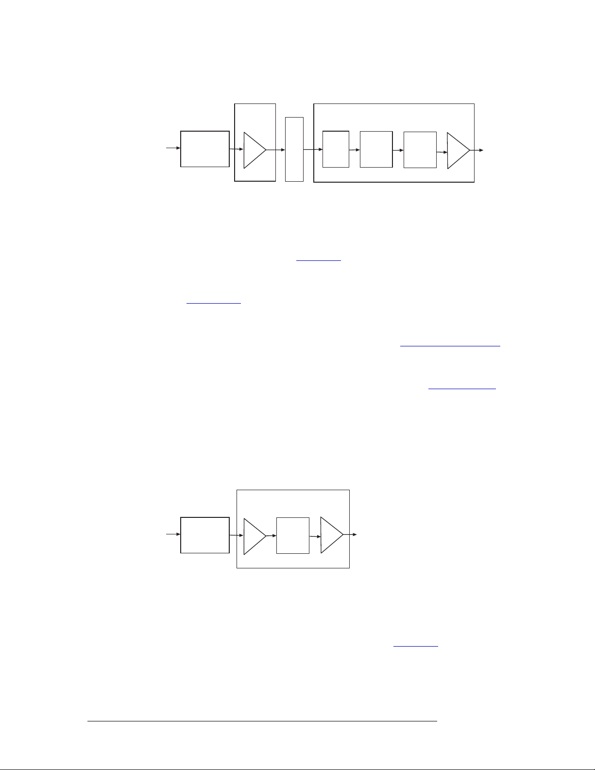
2. Introduction
Active Cards
Figure 2-21 shows the SD signal path.
Input Card
Cable
I/O
Connectors
Figure 2-21. SD Digital Video Signal Flow
on backplane
(up to 16)
Equalizers
Recr
Motherboard
Output Card
XPT
128x16
Re-
clocker
I/O
(up to 16)
Connectors
Classic SWB
The Classic SWB input card set (EM0395) is composed of two cards and occupies two slots in the
router. The backplanes housing I/O connectors for receiving and distributing SWB signals are
active and unique to video signals. (See Backplanes
planes: one for inputs (EM0396) and one for outputs (EM0424).
There is a jumper that configures the Classic SWB card set for DVB/ASI operation. For more information, see Configuration
on page 67.
A single Classic SWB card set can switch 16 inputs x 16 outputs. Two card sets can be linked
together such that the inputs from each card set is sent to the other card set, to create a switching
configuration of 32 inputs x 32 outputs. For more information, see Switching Configurations
page 8.
Up to 16 incoming signals are received through connectors on an associated I/O backplane. Equalizers on the backplane automatically compensate for length of cable. (See Technical Details
page 83.) The equalized signal is forwarded to the card set and a crosspoint array (32 inputs x 16
outputs) for switching. From the crosspoint, the SWB signal is forwarded to a re-clocker, which
automatically switches between 143, 177, 270, 360, and 540
rates. If the sample rate is non-standard, the re-clockers pass the signal to the backplane for distribution without attempting to re-clock it. The signal is then sent to a cable driver on the backplane,
which forwards the signal to backplane I/O connectors for distribution.
on page 13.) There are two types of back-
on
on
Mb/s, and 1.483 and 1.485 Gb/s sample
Figure 2-22 shows the Classic SWB signal path for a single card set:
Cardset
Cable
I/O
Connectors
Figure 2-22. Classic SWB Video Signal Flow
on backplane
(up to 16)
Equalizers
XPT
32x16
I/O
(up to 16)
Connectors
Standard SWB
Similar to the Classic SWB card set, the Standard SWB card receives and distribute SWB signals
through 16 BNC connectors, housed on a backplane. The backplanes for SWB incoming signals
and outgoing signals are active and unique to video signals. (See Backplanes
There are three types of Standard SWB cards: an input card, a main output card and expansion output cards. Depending on how the cards are combined, different switching configurations can be
created. A single set of Standard SWB output cards can switch 128 inputs x 64 outputs. By install-
28 Rev 2.5 • 24 Sep 09
on page 13.)
Page 39
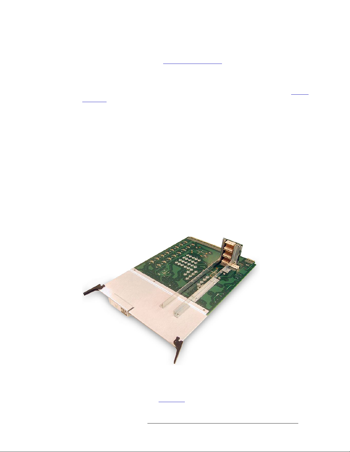
2. Introduction
Active Cards
ing a second set of Standard SWB output cards, the configuration can be doubled 128 inputs x 128
outputs. For more information, see Switching Configurations
Input Cards
The Standard SWB input card (EM0466) receives 16 SWB signals through the active backplane
connectors. Equalizers on the backplane automatically compensate for length of cable. (See Techni-
cal Details on page 83.) The equalized signal is forwarded to the input card. The input card buffers
the equalized incoming signals from the backplane and forwards the signal to the motherboard.
Output Cards
There are two Standard SWB output cards: a main output card (EM0463) and an expansion output
card (EM0465). The main output card has a “wing” that extends into the three slots to the right of
the slot occupied by the main part of the card, using all four output slots on the side of the frame in
which it is installed. (See Figure 2-23 on page 29.) Connectors on the wing mate with up to three
optional expansion output cards, installed to the right of the main Standard SWB card.
The Standard SWB main output card receives all 128 available SWB sources from the motherboard. Two 64 inputs x 64 outputs crosspoint arrays on the main output card can switch up to 128
inputs x 64 outputs. From the crosspoint, 16 outputs are re-clocked and sent to the main card’s corresponding active backplane through connections to the motherboard. The crosspoint forwards the
remaining 48 outputs to the wing connector, which feeds the signals to any installed expansion output cards. When installed, the expansion output cards are connected to the wing connector, the
motherboard and associated backplanes.
on page 8.
Figure 2-23 shows the EM0463 module and wing connector:
Figure 2-23. Standard SWB Main Output Card with Wing
Analog Video
Incoming and outgoing analog video signals are received or distributed through 16 BNC connectors housed on a backplane. (See Backplanes
card manage NTSC and PAL signals transparently; no adjustment of jumper settings is required.
on page 13.) The analog video input card and output
NV5128 Multi-Format Router • User’s Guide 29
Page 40

2. Introduction
Active Cards
Input Card
The analog video input card (
I/O connectors. Incoming signals are directly coupled to a differential Op-amp, which act as input
buffers. The buffered outputs are applied to balanced bus drivers that forward the signal to the
motherboard.
Output Card
The analog video output card (EM0376) receives up to 16 signals from the motherboard. Incoming
analog video signals are buffered and converted to unbalanced video signals. The signals are then
forwarded to four crosspoint arrays (32 inputs x 16 outputs) for switching creating a 128 inputs x
16 outputs switching matrix. From the crosspoints, the signals are sent to a 4 x 1 Mux, which forwards the signals to a buffer before sending the signals to backplane I/O connectors for distribution.
Figure 2-24 shows the signal path for analog video signals:
EM0375) receives up to 16 analog video signals through backplane
Input Card
I/O
(up to 16)
Connectors
Figure 2-24. Analog Video Signal Flow
Motherboard
Output Card
XPT
32x16
XPT
32x16
XPT
32x16
XPT
32x16
MUX
4x1
I/O
(up to 16)
Connectors
Analog Video Converter
The Analog Video Converter (AVC) input card and output card add versatility to the NV5128
Multi-Format Router by converting signals, as follows:
• The AVC input card converts incoming composite analog video signals (NTSC or PAL) to SD,
serially-interfaced signals.
• The AVC output card accepts SD inputs from the motherboard and outputs them as analog composite signals in NTSC or PAL format.
An AVC input card can be paired with an AVC output card, SD output card or SWB output card.
An AVC output card can be paired with an AVC input card, SD input card or SWB input card. Any
video I/O card paired with an AVC input card or AVC output card must be able to manage a signal
rate of 270
Mb/s.
Converting a signal from analog to SD delays the signal by approximately 1-1/4 lines; frame synchronization and sub-carrier phase alignment are not maintained with respect to reference. AVC
input cards and output cards provide an economical way to convert NTSC/PAL inputs where signal
30 Rev 2.5 • 24 Sep 09
Page 41

2. Introduction
Active Cards
timing is not critical; there is a processing delay of approximately 4 pixels when using an AVC output card. With AVC output cards, frame synchronization and sub-carrier phase alignment are not
maintained with respect to reference. This timing is not adjustable.
Incoming and outgoing analog video signals are received or distributed through 16 BNC connectors housed on a backplane. (See Backplanes
AVC Input Card
The AVC input card (
EM0432) receives up to 16 composite analog video signals through backplane
I/O connectors. Each incoming signal is received by a differential input amplifier. The amplifiers
create single-ended outputs. The outputs are forwarded to anti-aliasing filters and then onward for
processing by an NTSC decoder (AVC) synchronized to 27
a SMPTE 259M formatter and bus driver. A 27
converter, reduces jitter during the data formatting process. The SD output is line-locked to the
incoming composite signal.The signals is then forwarded to the motherboard for distribution to a
SD output card (EM0384) or to an AVC output card (EM0433).
AVC Output Card
The AVC output card (EM0433) receives up to 16 SD signals from the motherboard. Differential
inputs from the motherboard are buffered by receivers on the output card. The signals are fed to a
128 inputs x 16 outputs crosspoint array for switching. Each of the 16 outputs is re-clocked and
deserialized. The signals are then encoded as baseband video signals, buffered by an output line
driver and sent to the backplane as composite analog.
on page 13.)
.MHz. The converter feeds the signal to
MHz phase-locked loop (PLL), locked to the video
Figure 2-25 shows the signal path through the two AVC I/O cards:
Input Card
Anti-
I/O
(up to 16)
Connectors
Motherboard (x16)
Figure 2-25. Analog Video Conversion Signal Flow
aliasing
filter
XPT
128x16
Output Card
A/D
Converter
(27
Mhz)
Re-clocker
Deserialized
D/A
Converter
I/O
Motherboard
(up to 16)
SD or AVC
Connectors
I/O
(up to 16)
Connectors
Machine Control Signals
The NV5128 supports machine control signals, either EIA-232 or EIA-422. Machine control signals are used to communicate between two machines, such as editing equipment and a tape
machines. This enables control of two machines through a single interface.
The Machine Control card set (EM0482) is composed of two cards and occupies two slots in the
router. The Machine Control card set receives 32 signals through two passive backplanes, each containing 16 RJ-45 connectors. (See Backplanes
on page 13.)
NV5128 Multi-Format Router • User’s Guide 31
Page 42

2. Introduction
Active Cards
The Machine Control card set differs from other modules in that it is bi-directional. A Machine
Control card set is neither an “input” nor an “output” card; it carries signals in both directions. The
architecture of the Machine Control card set is similar to the Classic SWB card set: the port card set
occupies two slots and uses two backplanes supporting up to 32 signals. (See Classic SWB
page 28.) Two card sets can be linked together, cross-coupling the inputs from each card set to the
other card set, creating 64 ports. For more information, see Switching Configurations
The port card set has one jumper used to configure the card set to function as a standalone 32-port
card set regardless of where it is installed in the frame. This means that two 32 inputs x 32 inputs
matrixes can be installed instead of one 64 inputs x 64 inputs matrix. For more information, see
Configuration
Incoming and outgoing signals are buffered by differential transmitters and receivers on the card
set. When two Machine Control card sets are connected, signals are sent directly to the 64 inputs x
32 outputs crosspoint array on each card set for switching (creating a 64 inputs x 64 outputs switching matrix) without going through the motherboard.
Figure 2-26 shows the signal flow path through a pair of Machine Control card sets.
EM0482 Port Module
on page 67.
Slots 12 and 13
64×32 Crosspoint Array
and Port Control Logic
32
Transmitters
(×32)
32
Receivers
(×32)
on
on page 8.
Slots 14 and 15
EM0482 Port Module
32
32
32
64×32 Crosspoint Array
and Port Control Logic
32
32
Receivers
(×32)
32
Transmitters
(×32)
Modules
Motherboard
Special Motherboard Traces
16
16 16
116
16
1732 3348 4964
EM0383
Backplanes
RJ-45 Ports
16
16
16
16
Figure 2-26. Machine Control Signal Flow (64-Port Configuration)
Time Code Signals
The NV5128 supports SMPTE time code signals. A time code is a sequence of numeric codes generated at regular intervals by a timing system. Time codes are usually used to synchronize a variety
of signals to a specific start and end time, without regard to any other timing device. For example, a
production plant may use a time code signal to which all signals distributed within the plant are
synchronized. This ensures synchronization of signals to a single “master” clock instead of individual equipment clocks.
Input Card
The time code input card (EM0408) receives 16 time code signals through 16 Phoenix connectors
housed on a backplane. (See Backplanes
code input signals from the input backplane. The receivers send the single-ended outputs to Low
Voltage Differential Signal (LVDS) buffers and then to the motherboard. The signal format on the
motherboard is differential.
on page 13.) 16 differential input receivers accept time
32 Rev 2.5 • 24 Sep 09
Page 43

2. Introduction
Active Cards
Output Card (EM0409)
The time code output card (EM0409) receives up to 16 inputs from the motherboard. Differential
receivers buffer the inputs and forward them to a 128 inputs x 16 outputs crosspoint array for
switching. The time code outputs are reformatted to comply with SMPTE standards and then sent to
the output backplane through time code signal differential line drivers.
Figure 2-27 shows the time code signal path:
Input Card
I/O
Figure 2-27. SMPTE Time Code Signal Flow
Recr
(up to 16)
Connectors
Motherboard
Recr
Output Card
XPT
128x16
Reformatter
I/O
(up to 16)
Connectors
NV5128 Multi-Format Router • User’s Guide 33
Page 44

2. Introduction
Active Cards
34 Rev 2.5 • 24 Sep 09
Page 45

3. Installation
Chapter 3 provides installation and connection instructions. It presents the following topics:
• Summary
• Package Contents
• Preparing for Installation
• Rack Mount
• Connecting the Router to Power
• Installing Backplanes
• Installing Active Cards
• Making Signal Connections
• Making Reference Connections
• Making Router Control System Connections
• Making Diagnostic Connections
• Making Alarm Connections
• Verification
Summary
When setting up the NV5128 for the first time or reconfiguring a NV5128, there are certain steps
that must be performed. It is recommended that initial installation and later reconfiguration tasks be
performed in a specific order to avoid possible complications.
Perform installation and reconfiguration tasks in the following order:
1 Mount the router in a rack. If reconfiguring, skip this step if the router is already rack mounted
and not being remounted. See Rack Mount
2 Connect power, being sure to install PS6000 modules after power is connected. See Connecting
the Router to Power on page 38.
3 Install backplanes in the appropriate rear backplane slots. If reconfiguring, removed backplanes
and reinstall in the newly desired slots. See Installing Backplanes
4 Install active cards in the appropriate front card slots. If reconfiguring, removed cards and rein-
stall in the newly desired slots. Make sure that the appropriate backplane is installed for each
active card. See Installing Active Cards
5 Make connections between the source of incoming signals and the destination of outgoing sig-
nals, and the router. If reconfiguring, change signal connections to match new backplane and
active card configuration. See Making Signal Connections
6 Make connections to signals acting as references for audio and video signals. If reconfiguring,
verify that all necessary reference connections are made for the signals being routed. See Mak-
ing Reference Connections on page 57.
on page 37.
on page 40.
on page 44.
on page 50.
NV5128 Multi-Format Router • User’s Guide 35
Page 46

3. Installation
Package Contents
7 Make connections between the router and the router control system. If reconfiguring, skip this
step if all necessary router control system connections are still adequate. See Making Router
Control System Connections on page 59.
8 Make permanent or temporary diagnostic connections. Diagnostic connections enable the
router and UniConfig to communicate. This is important when initially configuring the router
and any time the router is reconfigured. See Making Diagnostic Connections
9 Connect the alarm connection on the router to an external indicator. If reconfiguring, skip this
step if alarm connections are still adequate. See Making Alarm Connections
10 Install UniConfig. If reconfiguring, UniConfig does not need to be reinstalled. See the UniCon-
fig User’s Guide.
Package Contents
When your NV5128 products from Miranda arrive, immediately inspect the shipping container for
any obvious damage. If the container is damaged, unpack and inspect the contents. If the contents
are damaged, notify the carrier immediately.
on page 62.
on page 64.
When unpacking the shipping container, look for the packing slip and compare it against the contents to verify that everything ordered was received. If anything is missing (or if equipment is damaged unrelated to shipping), please contact Miranda. For contact information, see Technical
Support Contact Information on page iii.
The package does not contain mounting rack, network cables, video cables, mounting screws, or
grounding wire.
This document does not address the shipment or installation of any other equipment or software
that can be used in conjunction with the routers, including router control systems or configuration
software.
Preparing for Installation
You will need the following items before getting started:
A PC running Windows
required only for system configuration.
PC hardware requirements:
CD drive
EIA-232 serial COM port (DE9) capable of operating at 38.4
10BaseT or 10/100BaseT (preferred) Ethernet port.
100
Mb/s Ethernet switch with at least 4 ports.
®
2000 or higher, or Windows XP Professional.® This PC is
kb/s.
RJ-45 connectors and Ethernet cables (category 5).
DE9 connectors EIA-232 serial cable.
75
Ω BNC connectors and coaxial cables.
50
Ω BNC connectors and coaxial cables.
36 Rev 2.5 • 24 Sep 09
Page 47

Rack Mount
3. Installation
Rack Mount
Reference audio and video source at the line rate appropriate for your system.
Frame rack suitable for mounting the router and NV6257 power supply.
Depending on the nature of your usage, you will also need an assortment of video and audio cables,
video and audio sources, video monitors, audio monitors, audio meters, small hardware (screws,
nuts, washers), and tools.
The NV5128 is designed to mount in a standard EIA 19” (483 mm) rack.
How to rack mount the router
1 Determine the placement of the router frame in the rack, and the rack in the facility. When plac-
ing the frame and rack, keep in mind the following requirements:
The router requires 8RUs (14
Be sure to locate the rack near an accessible AC source power outlet.
To ensure proper cooling, leave space for unrestricted air flow through the front of the router,
and a minimum of six inches clearance at the rear where the cooling fans are located.
2 If the router was shipped with the PS6000 power supply modules in the frame, remove them to
make the frame lighter for installation.
inches, 355.6 mm) of vertical space.
Important Do not reinstall the PS6000 power supply modules. The modules are installed
after power is connected.
3 If the router was shipped with the active cards (e.g., circuit boards) and fan tray in the frame,
consider removing them to make the frame lighter for installation. If removing active cards, be
sure to note which card was installed in which slot for later reinstallation.
Caution Handle all circuit boards with care. Be sure to use ESD protection and place
the circuit boards in ESD bags or on an ESD surface.
4 Lift the router frame into position and attach the router frame to the front of the rack with the
appropriate screws. Have helpers assist in the installation, or use a jack, to keep the frame
aligned in the rack. Do not use modules or other internal components as hand holds. Place
screws in all frame mounting screw holes.
5 If not already installed, install the fan tray by inserting tray in the fan tray slot, located at the top
when facing the front of the router frame, as shown in Figure 2-3 on page 11. The fan tray is
installed right-side up.
6 Reinstall any previously removed active cards (circuit boards). Be sure to install them in the
correct location. For installation instructions, see Installing Backplanes
7 Close the front door.
on page 40.
NV5128 Multi-Format Router • User’s Guide 37
Page 48

3. Installation
Connecting the Router to Power
Connecting the Router to Power
The NV5128 uses the PS6000 power supply module. The NV5128 requires a minimum of one
PS6000 power supply module (plus one optional modules for redundancy). The router requires two
AC power cords.
The NV5128 has a ground lug on the back of the router. Whether to ground or not is optional and
failure to connect the ground does not affect normal operation. However, grounding helps protect
you and your equipment in case of a power anomaly such as a lightning strike.
Power Supply Monitor and Alarms Connections
The NV5128 has a ‘Power Supply Alarm’ connection, located on the rear of the frame. The connection carries alarm and temperature signals to the router. This connection is connected at the
same time the power connections are made.
Power Cords and Branch Circuits
For added protection in the event of a mains power failure, it is recommended that each power cord
connected to the router frame be connected to a separate branch circuit. A wire bail can be used to
hold the power cable in place to reduce the possibility of an accidental disconnect.
The power cords are the only means of disconnecting AC power. Clearly mark the line side power
connection with its function so that in the event of an emergency, power can be disconnected
quickly.
Making Power Connections
Important! Be sure to connect to AC power before installing PS6000 power supply modules. Connecting to AC power after PS6000 modules are installed may result in an electric shock.
How to connect the router to a power source
1 Locate the power cords and PS6000 power supply modules.
2 If not already removed, facing the front of the router, remove all PS6000 power supply mod-
ules, as shown in Figure 3-1.
38 Rev 2.5 • 24 Sep 09
Page 49

3. Installation
Connecting the Router to Power
49-
POWER
12345
33-
17-
1-
2
1
32
16
1-
4
3
5
64
48
16
49-
17-
33-
6
7
64
32
48
48V
GND
+
1
2345
PS6000 Primary Power Supply
Module Slot (PS1)
INPUTSOUTPUTS OUTPUTS
8
97-11211113-128
81-
PS6000
65-
1
9
96
80
0
12345
POWER
113-128
1
1
2
3
97-112
65-
81-
1
1
1
80
96
6
5
4
PS6000 Secondary Power Supply
Module Slot (PS2)
48V
GND
+
1
2345
PS6000
Figure 3-1. PS6000 Power Supply Module Slot - No Cards Installed (Front View)
3 Facing the rear of the NV5128, connect one of the two power cords to ‘PS1’:
PRI CTRL
SEC CTRL
CTRL 1
AES
REF
1
VIDEO
REF 1
CTRL 1
CTRL 2
DIAG
PRI CTRL
10/100BT
LOOP
THRU
ALARMS
CONTROL NO. 9K50
LOOPTHRU
NVISION
AUX BUS
VIDEO
REF 2
(2)
TIMECODE
PROFESSIONAL
VIDEO/AUDIO
CTRL 2
DIAG
SEC CTRL
10 B 210 B 2
10/100BT
AES
REF
2
LOOP
THRU
INPUTS
97-1121181-961065-80
113-128
12
49-64833-48717-3261-16
9
5
CAUTION
THIS EQUIPMENT HAS
MORETHAN ONE
POWER SUPPLYCORD .
TO REDUCETHE RISK
OF ELECTRIC SHOCK,
DISCONNECT 2 POWER
SUPPLYCORDS BEFORE
SERVICING.
PLEASE READ
INSTRUCTION MANUAL
BEFORECONNECTING
EQUIPMENTTOTHE MAINS
FUSESLOCATED ON
POWER SUPPLIES
T 8.0A 250V
FOR 90-130V
T 6.3A 250V
FOR 180-250
PS 1
LEFT
PS 2
RIGHT
E146905
90-130/180-250V~
7.5A/3.75A
50/60Hz
660WATTS MAX
PS ALARMS
1 AND 2
12COM
NORMALLY
CLOSED
~
~
Power
Connections
Figure 3-2. Power Connections - No Backplanes Installed (Rear View)
4 Connect the other end of the power supply cable to a source of AC power source (90-130/180-
250
VAC, 50/60 Hz).
5 Facing the rear of the NV5128, connect the remaining power cord to ‘PS2’, as shown in
Figure 3-2 on page 39.
NV5128 Multi-Format Router • User’s Guide 39
Page 50

3. Installation
Backpl
Installing Backplanes
6 Connect the other end of the power supply cable to a source of AC power source (90-130/180-
230
VAC, 50/60 Hz).
7 Install the PS6000 power supply modules as follows:
a Facing the front of the NV5128, install the primary PS6000 power supply module in the
primary power supply slot, as shown in Figure 3-1 on page 39.
b (Optional) Facing the front of the NV5128, install the redundant PS6000 power supply
module in the secondary power supply slot, as shown in Figure 3-1 on page 39.
8 Facing the rear of the NV5128, connect the ground lug to ground using a copper wire from 14
to 6 AWG. The ground lug is located in the lower, left-hand corner.
Installing Backplanes
The NV5128 features backplanes that correspond to different signal types. A backplane is a separate metal plate that contains connectors for receiving or distributing signals for an associated input
card or output card. Backplanes are inserted into empty slots in the back plate on the rear of the
router. Be careful to install backplanes in the correct slot. With the exception of the SWB input
backplane, the SWB output backplane and the SD input backplane, backplanes are passive and contain no active circuitry. Backplanes containing active components receive power from the corresponding input card or output card installed in the slot the backplane serves.
Figure 3-3 shows the backplanes installed on the rear of the router. For more information about
backplanes, and the type of signal supported, see Backplanes
anes
Output 65–128 Input 128–1 Output 64–1
on page 13.
Figure 3-3. NV5128 Frame with Backplanes (Rear View)
40 Rev 2.5 • 24 Sep 09
Page 51

3. Installation
R
Installing Backplanes
Each backplane must have a corresponding input card or output card installed in the associated slot.
For example, if a backplane for receiving SD signals is installed, a corresponding SD input card
must be installed in the associated card slot. Typically, for each backplane installed to receive a specific type of signal, a corresponding backplane is installed that distributes the same type of signal.
For more information, see Installing Active Cards
on page 44.
Caution Although different backplanes may appear to be identical (e.g., contain the same
type of connectors), some have active components while others do not. Always
verify that the correct backplane is being for the associated front-loaded active
input card or output card.
Installing Classic SWB Backplanes
Classic SWB backplanes contain 16 BNC connectors and must be installed in specific slots. Install
these backplanes first. Before installing Classic SWB backplanes, review Rules for Classic SWB
Card Sets on page 46.
When installing Classic SWB backplanes in the frame, the silk-screened slot designations on the
rear of the frame are incorrect. To remedy this, a thin plate with the correct I/O designations is
included with the Classic SWB backplanes. This plate should be installed on top of the existing legends.
Each Classic SWB card set requires two backplanes: One is a 16-input active backplane; it includes
automatic cable equalization circuits for the 16 inputs. The other is an output backplane with active
line drivers for the 16 outputs. One Classic SWB card set supports 16 inputs x 16 outputs.
How to install a Classic SWB backplane
1 Facing the rear of the router, locate the legend plate, as shown in Figure 3-4.
2 Remove the two screws, as shown Figure 3-4.
emove these two screws
OUTPUTS
SWB
81-96
Figure 3-4. Classic SWB Legend Plate (Rear View)
15
113-128
113-128
14
INPUTS
SWB
13
OUTPUTS
OUTPUTS
SWB
SWB
97-112
97-112
11
12
SWB
97-112
11
3 Place the new Classic SWB legend plate over the existing plate, aligning the two screw holes.
4 Reinstall the screws removed in Step 2.
5 Locate the Classic SWB backplanes for inputs (EM0396) and outputs (EM0424).
6 Important: If any Classic SWB card sets are currently installed, unseat the card set before
installing the associated backplanes.
NV5128 Multi-Format Router • User’s Guide 41
Page 52

3. Installation
Installing Backplanes
7 Remove any blank plate covering the desired slot by loosening the spring-loaded retention
screws using a #1 Phillips screwdriver. Gripping the screws, gently pull the blank plate free
from the frame, using a slight rocking motion if needed. Use caution to avoid damaging connector pins.
Or
If reconfiguring the router, relocate backplanes as needed.
8 Insert the new backplane into the frame being sure to align the printed circuit board with the
stamped guides in the frame. Use gentle pressure at the top of the backplane to ensure the backplane connector is fully mated with the motherboard.
Classic SWB backplanes must be installed in specific slots, as follows:
Number of Classic SWB Card
Sets installed
Part Number: EM0396 EM0424
One (16 x 16) Install in slot 12 Install in slot 13
Two (32 x 32) Install in slots 11 and 13 Install in slots 12 and 14
See
Figure 2-4 on page 12.
Slot Number Slot Number
9 Use a #1 Phillips screwdriver to tighten the two spring-loaded backplane retention screws.
10 To maintain proper airflow for cooling, cover any unused backplane slots with a blank plate.
Installing Machine Control Backplanes
The Machine Control card set requires two backplanes. If you are installing a single Machine Control card set, the two backplanes may be located in any two adjacent slots associated with the
Machine Control card set. If you are installing two Machine Control card sets (64-port configuration), the two backplanes must be installed in specific slots.
Miranda offers an optional connector breakout panel that can be used to convert up to 64 RJ-45
connectors on the router backplane to 9-pin subminiature D connectors (DE9). This breakout panel
occupies 4RUs and hinges open for easy access and to facilitate cable routing. The DE9 connector
wiring follows SMPTE-defined pin assignment standards. For more information, see Machine Con-
trol Breakout Panel on page 43.
How to install a Machine Control backplane
1 Facing the rear of the router, remove any blank plate covering the desired slot by loosening the
spring-loaded module retention screws using a #1 Phillips screwdriver. Gripping the screws,
gently pull the blank plate free from the frame, using a slight rocking motion if needed. Use
caution to avoid damaging connector pins.
Or
If reconfiguring the router, relocate backplanes as needed.
2 Insert the new backplane into the frame being sure to align the printed circuit board with the
stamped guides in the frame. Use gentle pressure at the top of the backplane to ensure the backplane connector is fully mated with the motherboard.
42 Rev 2.5 • 24 Sep 09
Page 53

3. Installation
Installing Backplanes
Machine Control backplanes must be installed in specific slots, as follows:
Configuration Card Set 1 Card Set 2 Backplane Modules
32-port (1–32) Install this card set in any two
adjacent slots. Slots 11 and 12
are the preferred locations.
Note: you cannot install this
card slot in slots 13 and 14
unless a jumper is moved out of
its “normal” position. See
Machine Control Card Set
Jumpers on page 69.
64-port (1–32,
33–64)
Figure 2-4 on page 12.
See
Install in slots 11 and 12 Install in slots 13
3 Use a #1 Phillips screwdriver to tighten the two spring-loaded backplane retention screws.
4 To maintain proper airflow for cooling, cover any unused backplane slots with a blank plate.
Machine Control Breakout Panel
Miranda offers an optional breakout panel (BP2-PORT-64) that can be used with up to 4 machine
control backplanes. This 4RU breakout panel connects internally 64 RJ-45 connectors to 64 DE9
connectors. For more information, see Machine Control Breakout Panel
— Install two machine control
backplanes (EM0483) in rear
slots corresponding to the
front-loaded machine control
card set
Install four machine control
and 14
backplanes (EM0483) in rear
slots 11, 12, 13 and 14
on page 14.
The breakout panel allows you to use DE9 cables to your machine control devices.
How to install a Breakout Panel
1 Rack-mount the (4RU) breakout panel in a convenient location.
2 Cable one or more of its RJ-45 connectors to machine control ports of the NV5128.
3 Cable the matching DE9 connector(s) to the machine control devices (VTRs, etc.) that corre-
spond to the ports.
You can use any of the RJ-45/DE9 connector pairs on the breakout panel that you wish.
Installing Other Video, Audio and Time-Code Backplanes
After installing any Classic SWB or Machine Control backplanes, you can install any other needed
video, audio or time code backplanes. Install input and output backplanes in their respective locations as defined by your plan for populating the frame. Be careful not to confuse input backplanes
with output backplanes, and make certain that each backplane is installed in the correct slot.
Caution Be sure to cover any unused slots with blank plates. (See Installing Backplanes
on page 40.) Leaving openings in the rear may cause the frame to run warmer
than desired, possibly resulting in reduced reliability.
How to install a backplane
1 Unseat any SD input cards and SD output cards before removing or installing SD backplanes.
All other backplanes may be “hot swapped”.
2 Facing the rear of the router, remove any blank plate covering the desired slot by loosening the
spring-loaded module retention screws using a #1 Phillips screwdriver. Gripping the screws,
NV5128 Multi-Format Router • User’s Guide 43
Page 54

3. Installation
Installing Active Cards
gently pull the blank plate free from the frame, using a slight rocking motion if needed. Use
caution to avoid damaging connector pins.
Or
If reconfiguring the router, relocate backplanes as needed.
3 Insert the new backplane into the frame being sure to align the printed circuit board with the
stamped guides in the frame. Use gentle pressure at the top of the backplane to ensure the backplane connector is fully mated with the motherboard.
Note Before placing the router into service, be sure to verify the quantity and loca-
4 Use a #1 Phillips screwdriver to tighten the two spring-loaded backplane retention screws.
5 To maintain proper airflow for cooling, cover any unused backplane slots with a blank plate.
Installing Active Cards
tion of each backplane. Each backplane must have a corresponding input card
and output card.
The NV5128 router features several active cards that manage incoming signals, forward control
system commands, perform signal switching and distribute outgoing signals. Cards slide into a card
guide such that the connectors on the rear of the card interface with the motherboard. Each card has
two levers—one at the top and one at the bottom—that help eject the card for easy removal. For a
description of each card, see Active Cards
closed router door against the metal plate on the front of each card. All cards can be inserted and
removed with the power on.
There are many possible ways to populate the NV5128 frame with active cards. Before installing
any cards, make sure that for each input card and output card being installed in a slot, a corresponding backplane has been installed on the rear for that slot (see Installing Backplanes
Unlike other active cards, the Classic SWB card set and the Machine Control card set take up two
card slots. Each card set requires two associated backplanes, either for SWB or Machine Control
signals. For a description of each card, see Active Cards
backplanes, see Backplanes
Legend strips attached to the frame identify card locations. Output cards occupy the outer four slots
on either side of the frame, while input cards are located in the center eight slots. (See Figure 2-3 on
page 11.)
on page 13.
on page 21. Cards are held in place by pressure from the
on page 40).
on page 21. For a description of associated
Systems Clock Generator Card
If only one control card is being installed, an optional Systems Clock Generator card may be
installed to ensure system clock backup. See Systems Clock Generator Card
on page 21.
Cards Already Installed
The NV5128 is usually shipped with the active cards already installed in a specific order. Starting at
the lowest numbered input and output position (input 1 or output 1) and ending with the highest
input and output positions (input 128 or output 128), the boards are normally positioned as follows:
44 Rev 2.5 • 24 Sep 09
Page 55

3. Installation
Installing Active Cards
Analog Video
Analog Audio
SD Video
AES Digital Audio
Time Code
Machine Control
SWB Video
Card Installation Rules
The NV5128 was designed to make installation and expansion easy to perform. Some cards, such
as the control card and analog input card or analog output card, have jumpers or switches for
options. It is recommended that all jumpers and switches be set before placing the router into service. (See Configuration Tasks to Perform Before Installing Cards
There are some restrictions as to which slots cards can be installed in the NV5128 frame. Slots 11,
12, 13 and 14 are unique. (See Figure 2-3 on page 11.) These slots have inter-slot connectors that
allow signals to be passed between cards installed in these slots. This communication is necessary
for proper functioning of the Classic SWB card set and the Machine Control card set. The proceeding sections outline card and card set installation rules.
on page 47.)
Rules for Partitions and Card Installation
When installing or reconfiguring input cards and output cards in the router frame, it is important to
keep in mind how partitions for the router control system are created. Some third-party control systems require contiguous partitions, that is, that signal types are grouped together and placed in specific sequence in the router frame.
If using an NV9000 router control system partitions do not need to be contiguous. Using the “virtual level” feature in the NV9000, signal types can be organized into different levels, no matter
where the active cards are installed in the frame. For more information, see the NV9000 User’s
Guide.
If using a third-party router control system, active cards should be installed such that physical partitions are contiguous. This helps ensure maximum compatibility. If you are unsure about future
router control system applications, configuring the frame with contiguous physical partitions is the
best choice.
Rules for Standard SWB Cards
Standard SWB input cards (EM0466) may be installed in any input slot in the frame. There are two
types of Standard SWB output cards: main (EM0463) and expansion (EM0465). The main output
card occupies four slots in the router frame: one for the main output card with a “wing” and three
slots for optional expansion cards that mate with the wing on the main card. For more information
on card functions, see Standard SWB
When installing four or fewer standard SWB input cards, it is recommended that the cards be
installed in the right-hand input slots in the frame, beginning with slot 12 and working backwards.
This leaves room for installation of the standard SWB output cards. If your switching configuration
requires 64 SWB outputs or fewer, install the standard SWB main output card (EM0463) in slot 13.
Use slots 14, 15, and 16 for additional standard SWB expansion output cards (EM0465). If more
on page 28.
NV5128 Multi-Format Router • User’s Guide 45
Page 56

3. Installation
Installing Active Cards
than 64 outputs are desired, begin by installing input cards and output cards on the left side of the
router frame, when facing the front of the router, beginning with the first slots. (See Figure 2-3 on
page 11.) For more information on switching configurations, see Switching Configurations
8.
The following lists examples of different configurations using standard SWB cards:
on page
Slots for Standard SWB Input
Configuration
32 × 48 11, 12 13 14, 15
64 × 64 9, 10, 11, 12 13 14, 15, 16
96 × 96 4, 5, 6, 7, 8, 9 1, 13 2, 3. 4, 14
Card (EM0466)
Main Slots for Standard SWB
Output Card (EM0463)
Expansion Slots for Standard
SWB Output Card (EM0465)
Rules for Classic SWB Card Sets
Classic SWB card sets (EM0395) occupy two slots each. One card set serves as a SWB video
16×16 output crosspoint array. Two classic SWB card sets can be combined to create a 32×32 output crosspoint array. For more information on card functions, see Classic SWB
more information on switching configurations, see Switching Configurations
Each Classic SWB card set requires two backplanes: One is a 16-input active backplane; it includes
automatic cable equalization circuits for the 16 inputs. The other is an output backplane with active
line drivers for the 16 outputs. For more information, see Backplanes
on page 13.
Classic SWB card set must be installed in specific slots, as follows:
Slots for Input
Slots for Classic SWB
Configuration
16 × 16 Slots 12 and 13 Not used Slot 12 Slot 13
32 × 32 Slots 11 and 12 Slots 13 and 14 Slots 11 and 13 Slots 12 and 14
Card Set 1 (EM0395)
Slots for Classic SWB
Card Set 2 (EM0395)
Backplane Slot
Number (EM0396)
on page 28. For
on page 8.
Slots for Output
Backplane Slot
Number (EM0424)
See Figure 2-3 on page 11.
Rules for Machine Control Card Sets
A single machine control card set (EM0482) can be installed in any two adjacent slots to create a
32-port array. However, Miranda recommends that the first 32-port card set and backplane set be
installed in slot 11 and slot 12. If two Machine Control card sets are being combined, to create a 64port configuration, the card sets must be installed in slots 11 and 12 and in slots 13 and 14, respectively. (See Figure 2-3 on page 11.) It is not possible to install two independent 32-port module sets
in separate 32-port partitions. For more information on card functions, see Machine Control Signals
on page 31. For more information on switching configurations, see Switching Configurations
page 8.
46 Rev 2.5 • 24 Sep 09
on
Page 57

3. Installation
Installing Active Cards
The following lists examples of different configurations using machine control card sets:
Slots for Backplane
Configuration Slots for Card Set 1 (EM0482) Slots for Card Set 2 (EM0482)
32-port (1–32) Install in any two adjacent
slots. Slots 11 and 12 are
preferred locations.
64-port (1–32,
33–64)
Install in slots 11 and 12 Install in slots 13 and 14 Install four machine control
None Install two machine control
Limitations on Combining Classic SWB and Machine Control Card Sets
There are limitations if both the Classic SWB card set and the machine control card set are installed
in a single frame. It is not possible to install two machine control card sets in a 64-port configuration while a classic SWB card set is installed because both use the same slots.
The following lists possible combinations of classic SWB card sets and machine control card sets:
Combination Machine Control Card Sets (EM0482) Classic SWB Card Sets (EM0395)
Mixed machine control
and classic SWB
Machine control only 64-port (Slots 11, 12, 13 and 14) None
*Several independent 32-port machine control card sets may co-exist in the same frame.
32-port* (Install in any pair of adjacent
unused slots)
32 × 32 (Install in slots 11, 12, 13 and
14)
(EM0483)
backplanes in rear slots
corresponding to the
machine control card sets
backplanes in rear slots 11,
12, 13 and 14
Configuration Tasks to Perform Before Installing Cards
Before installing active cards, make sure all jumpers and switches are set to meet your configuration needs. For configuration instructions, see Setting Jumpers and Switches on Cards and Card
Sets on page 67.
• Control cards
trol systems and for AES reference impedance. All jumpers should be set before the card or
card set is installed.
• Analog audio cards
• Sample rate converter
ple rates to be supported and converts the signals to synchronous AES signals locked to a sample rate of 48
• Classic SWB card sets
• Standard SWB cards
clockers for operation with DVB/ASI signals.
• Machine control card sets
Machine Control card set even if another Machine Control card set is installed, allowing for two
32 inputs x 32 outputs matrices instead of one 64 inputs x 64 outputs matrix.
• Analog video conversion module
to SD format or converts SD formatted signals to composite analog video outputs in NTSC or
PAL formats.
— configure rear connections for Ethernet or to connect to third-party router con-
— set gain, mute detection and operating levels.
— enables up to 16 asynchronous AES inputs with a wide range of sam-
kHz.
— can configure the output cards for DVB/ASI operation.
— enable automatic re-clocking of the output signal and configure re-
— can configure the card set to function as a 32-port standalone
— converts incoming composite analog video (NTSC or PAL)
NV5128 Multi-Format Router • User’s Guide 47
Page 58
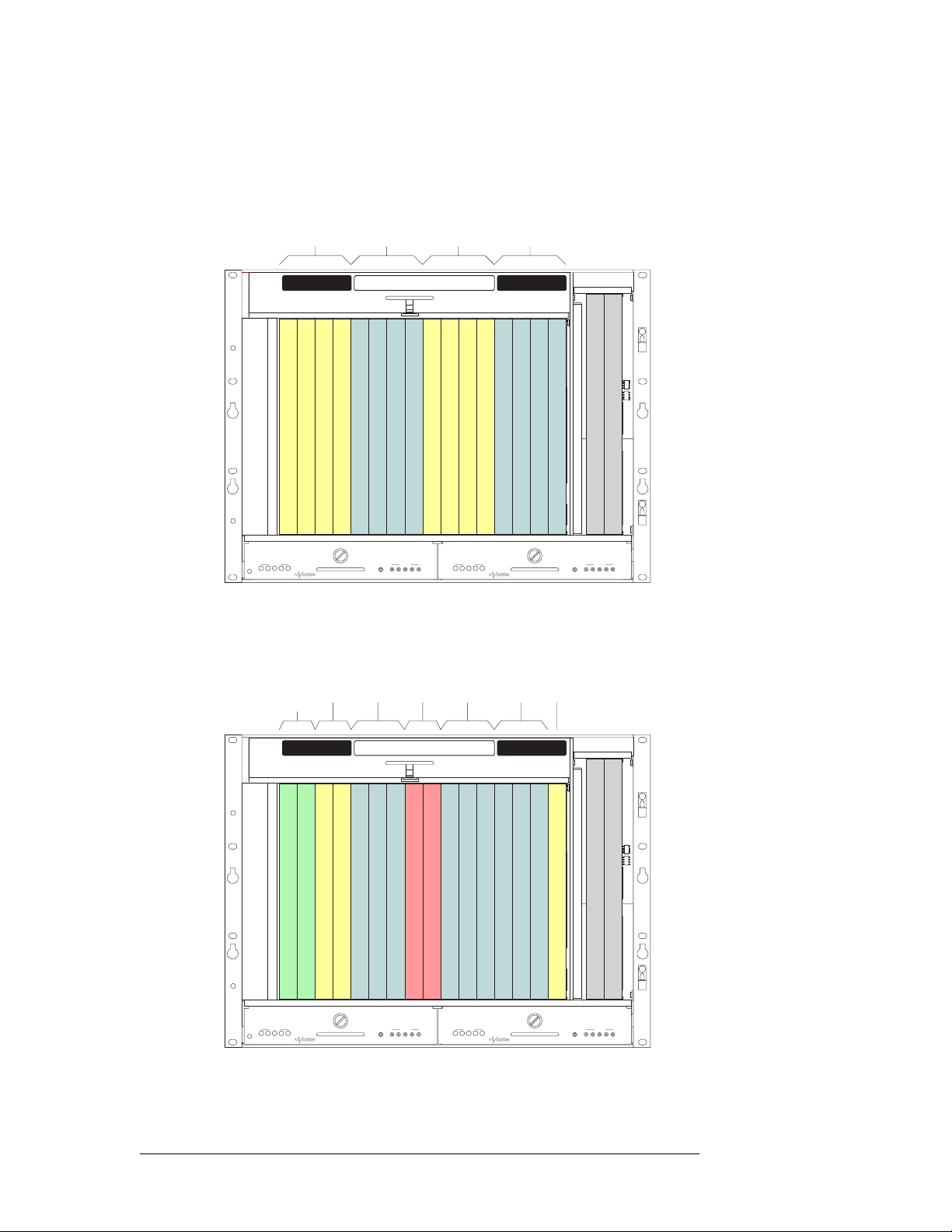
3. Installation
Installing Active Cards
Typical Card Combinations
The following are two examples of typical input card and output card combinations. Figure 3-5
shows a 64 inputs x 64 outputs analog video and 64 inputs x 64 outputs audio installation:
Analog AudioAnalog Video
Outputs 164 Inputs 164 Inputs 164 Outputs 164
INPUTSOUTPUTS OUTPUTS
33-48
1-16117-32233-48349-64
Outputs 116
Outputs 1732
Outputs 3348
1-16517-32649-64865-80981-961097-11211113-128
Inputs 116
7
Inputs 1732
Inputs 3348
Inputs 4964
Inputs 6580
4
Outputs 4964
Inputs 8196
Inputs 97112
12
Inputs 113128
113-1281397-1121481-961565-80
Outputs 113128
Outputs 97112
16
Outputs 8196
Outputs 6580
Secondary Control Card
Primary Control Card
POWER
12345
48V
GND
+
1
2345
PS6000
POWER
12345
48V
GND
+
1
2345
PS6000
Figure 3-5. Simple Layout
Figure 3-6 shows 48 SD inputs with 32 SD and 32 analog video outputs, 48 AES synchronous
inputs with 48 AES synch and 16 analog audio outputs, and a 32-port machine control card set:
SD
SD-to-
Video
Analog
Outputs
Video
132
Outputs
132
1-16117-32233-48349-64
Outputs 116
Outputs 1732
SD
1-16517-32649-64865-80981-961097-11211113-128
4
Outputs 3348
Outputs 4964
Video
Inputs
148
Inputs 116
Machine
33-48
7
Inputs 1732
Inputs 3348
Control
Sync
Ports
Inputs
132
INPUTSOUTPUTS OUTPUTS
Inputs 4964
Inputs 6580
Inputs 8196
AES
148
Inputs 97112
AES
Sync
Outputs
148
113-1281397-1121481-961565-80
12
Outputs 113128
Inputs 113128
Outputs 97112
Analog
Audio
Outputs
116
16
Outputs 8196
Outputs 6580
Secondary Control Card
Primary Control Card
POWER
12345
48V
GND
+
1
2345
PS6000
POWER
12345
48V
GND
+
1
2345
PS6000
Figure 3-6. Complex Layout
48 Rev 2.5 • 24 Sep 09
Page 59

3. Installation
Installing Active Cards
Installing Cards
All cards can be inserted and removed with the power on.
How to install active cards
Caution Do not drop, roughly handle, or stack active cards. If a card does not remove or
insert easily, stop installation activities and contact Miranda Technical Support.
(See Technical Support Contact Information
1 Set jumpers and/or switches on each card as needed. See Configuration Tasks to Perform
Before Installing Cards on page 47.
2 Facing the front of the router (door open), locate the control, input and output card slots.
3 Insert each card into the router frame by sliding it into a card guide in the slot. On all cards, the
metal plate on the front of the card should be facing outward and levers located at the top and
bottom of each card.
Insert the card in designated slots only, as follows (see Figure 3-7 on page 50):
• Insert a control card in each of the two control card slots for primary and secondary control
cards.
on page iii.)
Or
Insert one primary control card in the primary control card slot and a clock generator in the
secondary control card slot. See Systems Clock Generator Card
• Insert input cards for AES, analog video, analog audio or time code signals in the eight
center slots 5–12, based on your configuration.
• Insert classic SWB card sets in slots 11and 12 or 12 and 13. Specific slots used are based on
your configuration. See Rules for Classic SWB Card Sets
• Insert standard SWB cards in slots 1–16. Specific slots used are based on your
configuration. See Rules for Standard SWB Cards
• Insert machine control card sets in slot 11–14. Specific slots used are based on your
configuration. See Rules for Machine Control Card Sets
• Insert output cards for AES, analog video, analog audio or time code signals in the four left
slots 1–4 and the four right slots 13–16, based on your configuration.
on page 45.
on page 44.
on page 46.
on page 46.
NV5128 Multi-Format Router • User’s Guide 49
Page 60

3. Installation
Pri
Making Signal Connections
Fan Tr ay
Slots 1–4
(Outputs 1–64)
Slots 5–12
(Inputs 1–128)
Slots 13–16
(Outputs 128–65)
mary
Control
Secondary
Control
Main Power Supply (PS6000) Redundant Power Supply (PS6000)
Figure 3-7. Card Locations (Front View)
4 Press each lever downward so that the lever is tucked into the channel at the edge of the shelf on
the top and bottom. When the door is closed, pressure from the door ensures that the card is
fully seated with the motherboard.
5 Reinstall and close the frame front door after all cards have been installed. The door must be
closed for the router cooling system to work properly.
Making Signal Connections
For the NV5128 to route incoming and outgoing signals properly, the I/O connections housed on
backplanes on the rear of the router must be connected to cables that receive and distribute the signals. (See Backplanes
a maximum of 128 output connections. The total number of connections depends on the type of signals being routed and the corresponding backplane installed.
Figure 3-8 shows the rear of the router with backplanes containing connectors for receiving and
distributing signals and the location of inputs and outputs for signal connections.
on page 13.) The NV5128 contains a maximum of 128 input connections and
50 Rev 2.5 • 24 Sep 09
Page 61

3. Installation
O
I
O
Making Signal Connections
utput 65–128
Figure 3-8. NV5128 Frame with Backplanes (Rear View)
nput 128–1
utput 64–1
Instructions for making signal connections are listed by signal type in the proceeding sections.
AES Synchronous Signals
The NV5128 can route both balanced and unbalanced AES synchronous signals. Unbalanced signals are received and distributed through BNC connectors. Balanced signals are received and distributed through Phoenix connectors. Both types of connectors are housed on backplanes located on
the rear of the router. Each backplane contains 16 connections labeled ‘1’, ‘2’ and so on up to ‘16’.
The labels correspond to the signal numbers assigned to the signal passing through that connector.
For more information on backplanes, see Backplanes
About Phoenix Connectors
Phoenix terminal blocks accept a stripped (bare) wire 18 AWG or smaller. The connectors plug into
the mating receptacle on the backplane, using friction to hold them in place.
When using Phoenix connectors, be sure that only the bare wire end is captive under the clamp
screw and that there are no stray strands that can cause short circuits or accidental ground connections. Also make sure that the weight of the cable or cable bundle does not cause the connector(s) to
disengage over time. Provide adequate support for the cables 12 to 18 inches from the rear of the
frame.
on page 13.
NV5128 Multi-Format Router • User’s Guide 51
Page 62

3. Installation
Making Signal Connections
Balanced I/O
(Recommended)
Figure 3-9. Phoenix Connectors and Connection Methods
Unbalanced Inputs
(Not Recommended)
Unbalanced Outputs
(Not Recommended)
How to make connections for AES signals
1 Locate the AES input connections at the rear of the router, as shown in Figure 3-8 on page 51.
There are 16 BNC connectors on each backplane for AES unbalanced signals and 16 Phoenix
connectors on each backplane for AES balanced signals.
2 For each input connection, connect using the connector and cable appropriate for the type of
incoming signal:
For AES unbalanced signals, use a BNC connector and 75
For AES balanced signals, use a Phoenix connector and twisted-pair 110
Ω cable.
Ω cable. See About
Phoenix Connectors on page 51.
3 Connect the other end of the cable to the source of the signal.
4 Locate the AES output connections on the rear of the router, as shown in Figure 3-8 on page 51.
5 For each output connection, connect using the connector and cable appropriate for the type of
outgoing signal as described in Step 2.
6 Connect the other end of the cable to the signal destination.
7 Make other signal connections, as needed.
Analog Signals
The NV5128 can manage analog signals. Signals are received and distributed through DB25 connections, housed on backplanes. (See Backplanes
Each backplane contains four DB25 connectors. Each connector supports either stereo or mono signals:
•Stereo
• Mono
— 4 channel pairs, for a total of 16 stereo signals per backplane.
— 8 channels, for a total of 32 mono signals per backplane.
The DB25 connectors are labeled ‘1–4 Stereo’, ‘5–8 Stereo’, ‘9–12 Stereo’ and ‘13–16 Stereo’. The
labels correspond to the signal number assigned to the signals passing through that connector.
Analog signals are converted to digital (sample rate of 48kHz) for internal routing. (See Analog
Audio on page 25.) For proper conversion to occur, the system AES reference connection must be
connected. For instructions on connecting the AES reference, see AES Reference
52 Rev 2.5 • 24 Sep 09
on page 13.)
on page 57.
Page 63
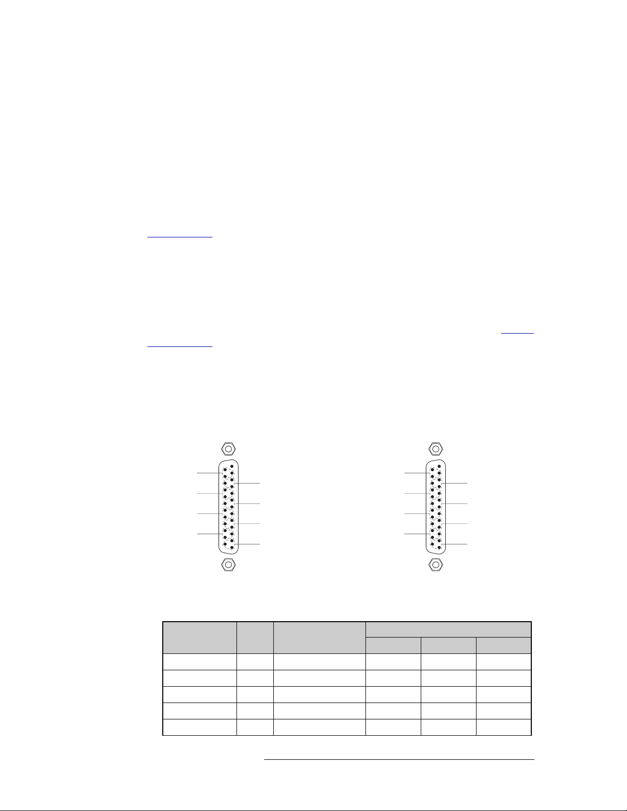
3. Installation
Making Signal Connections
The analog audio output card is designed to function in a voltage-matched system driving highimpedance loads. The output drivers are not designed to drive 600
overheat if used in a 600
Ω environment.
Mono Signals
How the NV5128 switches mono signals is dependent upon the router control system. Before setting up analog signals, make sure that the router control system can manage mono signals. All signal number labeling on the router frame refers to stereo signals, not mono signals. In order to
successfully install and implement the receiving and distributing of mono signals, great care should
be taken to avoid confusion. For more information on mono signals and signal number labeling, see
Mono Channels
on page 7.
Gain, Mute Detection and Operating Levels
When receiving and distributing unbalanced analog signals, a drop in level of 6 dB occurs. This is
due to one-half of the input signal being lost when the ‘-’ input is grounded and is normal. Using a
switch located on the analog audio input card, an additional 6
sate for the drop. In addition, mute detection and operating levels can be set, ensuring a clearer
audio signal. For instructions on setting gain, mute detection and operating levels, see Analog
Audio Switches on page 69.
Ω loads continuously and may
dB of gain can be added to compen-
How to make connections for analog signals
1 Locate the analog input connections on the rear of the router, as shown in Figure 3-8 on page
51. There are four DB25 connectors on each analog backplane.
2 For each analog input, connect using a DB25 connector and cable, wiring the connectors as fol-
lows:
SHLD
SHLD
SHLD
SHLD
25
12
Input 1
24
+
22
9
Input 3
21
+
19
6
Input 5
18
+
16
3
Input 7
15
+
25
14
13 Unused
1
Input 2
Input 4
Input 6
Input 8
11
SHLD
23
10
+
SHLD
8
20
+
7
SHLD
5
17
+
4
SHLD
2
14
+
1
SHLD
SHLD
SHLD
SHLD
Mono Stereo
Figure 3-10. Mono Pin Assignments
25
12
1 Left
24
+
22
9
2 Left
21
+
19
6
3 Left
18
+
16
3
4 Left
15
+
25
14
13 Unused
1
1 Right
2 Right
3 Right
4 Right
11
23
10
20
17
14
An optional pre-made DB25 male to pigtail breakout cable is available from Miranda
(NV5000-Cable1). The wiring details for this cable are as follows:
DB25 Connector Pin Number
Channel Pair Jacket Color
1 - Left 1 BROWN 24 12 25
1 - Right 2 RED 10 23 11
2 - Left 3 ORANGE 21 9 22
2 - Right 4 YELLOW 7 20 8
3 - Left 5 GREEN 18 6 19
Red (+) Black (–) GND
SHLD
+
SHLD
8
+
7
SHLD
5
+
4
SHLD
2
+
1
NV5128 Multi-Format Router • User’s Guide 53
Page 64

3. Installation
Making Signal Connections
Channel Pair Jacket Color
3 - Right 6 BLUE 4 17 5
4 - Left 7 VIOLET 15 3 16
4 - Right 8 GRAY 1 14 2
*Note: Pin 13 is not used.
Connect the signal or “hot” wire from the single ended source to the balanced input “+” connection. Connect the common or “shield” wire from the single ended source to the balanced input
“–” connection. Bridge the balanced input ground pin to the “–” pin, or single ended shield.
The following lists the signal managed by each pin:
Channel
1 - Left 24 12 & 25
1 - Right 10 11 & 23
2 - Left 21 9 & 22
2 - Right 7 8 & 20
3 - Left 18 6 & 19
3 - Right 4 5 & 17
4 - Left 15 3 & 16
4 - Right 1 2 & 14
*Note: Pin 13 is not used.
DB25 Connector Pin Number
Red (+) Black (–) GND
DB25 Connector Pin Number
Signal Common
3 Connect the other end of the cable for each input to the source of the signal.
4 Locate the analog output connections on the rear of the router, as shown in Figure 3-8 on page
51.
5 For each output, connect using a DB25 connector and cable, wiring the connectors as described
in Step 2.
6 Connect the other end of the cable to the signal destination.
7 Make other signal connections, as needed.
Video Signals
The NV5128 can support SD, SWB and analog video signals. Each requires a unique backplane
and signal connections. SD, SWB and analog video signals are received and distributed through 16
BNC connectors labeled ‘1’, ‘2’ and so on up to ‘16’. Connections are housed on a backplane
installed in the back plate. The labels correspond to the signal number assigned to the signal passing through that connector. (See Backplanes
SD signals and for incoming and outgoing SWB signals contain active connections; the backplane
for analog video signals contains passive connections. Do not intermix backplanes! SD and SWB
backplanes cannot be used for analog video signals, SD backplanes for SWB signals, and so on.
on page 13.) However, the backplanes for incoming
54 Rev 2.5 • 24 Sep 09
Page 65

3. Installation
Making Signal Connections
How to make video signal connections
1 Locate the input connections at the rear of the router, as shown in Figure 3-8 on page 51. There
are 16 BNC connectors on each SD, SWB or analog video backplane.
2 For each input, connect using a BNC connector and 75
Ω cable.
3 Connect the other end of the cable to the source of the incoming signal.
4 Locate the output connections on the rear of the router, as shown in Figure 3-8 on page 51.
5 For each output, connect using a BNC connector and 75
Ω cable.
6 Connect the other end of the cable to the distribution destination for the outgoing signal.
7 Make other signal connections, as needed.
Time Code Signals
Time code signals are received and distributed through Phoenix connectors. Connectors are housed
on backplanes installed in the router’s rear back plate. The backplane contains 16 connections
labeled ‘1’, ‘2’ and so on up to ‘16’. The labels correspond to the signal number assigned to the signal passing through that connector. (See Backplanes
Before making connections, review Phoenix wiring information. See About Phoenix Connectors
page 51.
How to make connections for time code signals
1 Locate the time code input connections on the rear of the router, as shown in Figure 3-8 on page
51. There are 16 Phoenix connectors on each time code backplane.
2 For each input, connect using a Phoenix connector and 110
cable, whichever you prefer. (See About Phoenix Connectors
on page 13.)
on
Ω twisted pair cable or coaxial
on page 51.)
3 Connect the other end of the cable to the source of the time code signals.
4 Locate the time code output connections on the rear of the router, as shown in Figure 3-8 on
page 51.
5 For each output, connect using a Phoenix connector (1 positive, 1 negative and 1 ground) and
110
Ω twisted pair cable or coaxial cable, whichever you prefer. (See About Phoenix Connec-
tors on page 51.)
6 Connect the other end of the cable to the signal destination.
7 Make other signal connections, as needed.
Machine Control Signals
Machine control signals are received and distributed through 16 RJ-45 connectors labeled ‘1–4’,
‘5–8’, ‘9–12’ and ‘13–16’. Connectors are housed on a backplane installed in the back plate. The
labels correspond to the signal numbers assigned to signals passing through that connector. (See
Backplanes
Machine control signal connections can be 16 RJ-45 connectors on a backplane or 64 DE9 connectors on a Machine Control converter backplane. For more information, see Machine Control Break-
out Panel on page 14.
NV5128 Multi-Format Router • User’s Guide 55
on page 13.)
Page 66
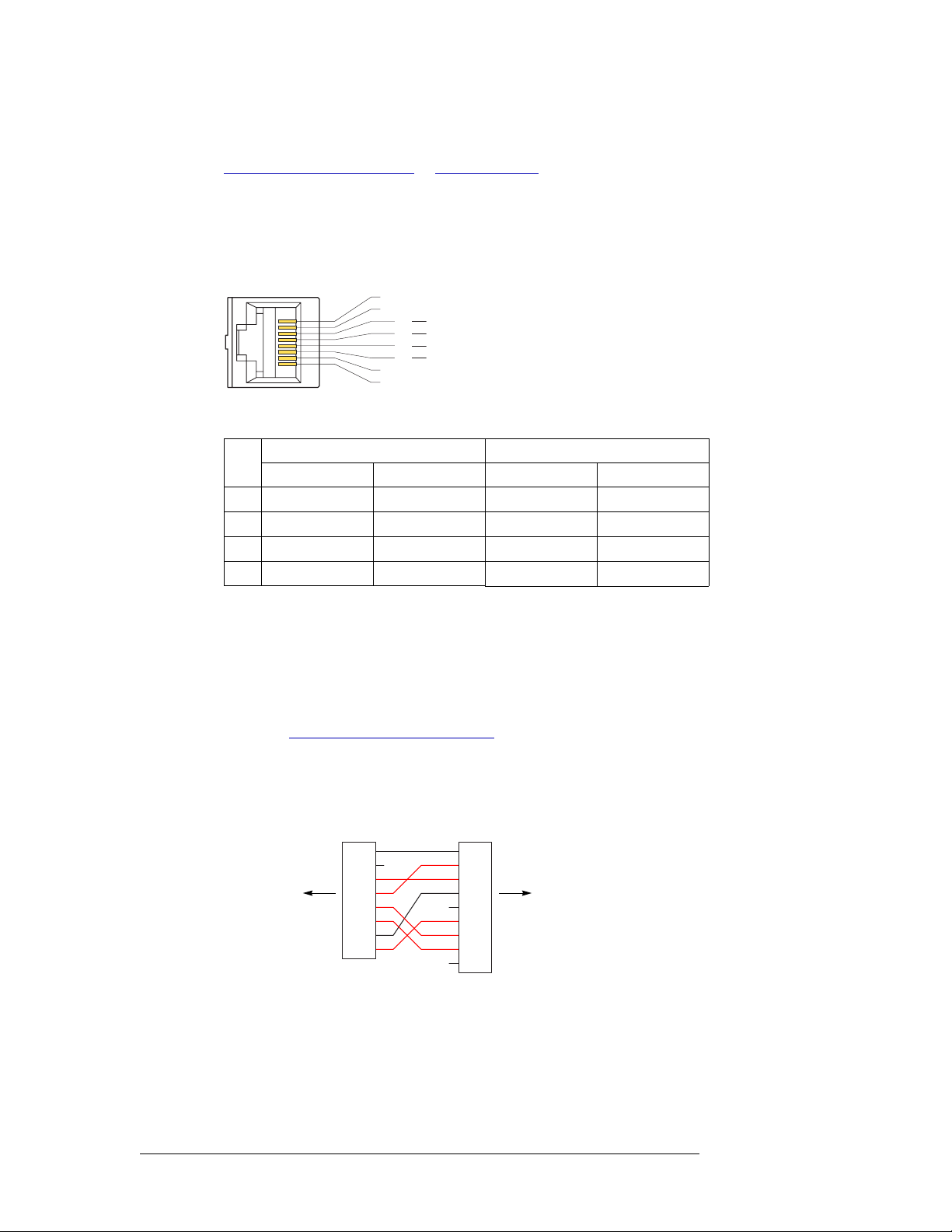
3. Installation
Making Signal Connections
Follow the instructions provided in the proceeding sections for the type of connector being used:
RJ-45 Connectors
RJ-45 Connectors
The RJ-45 connectors are wired according to industry standard SMPTE 207M. For best performance, use category 5 Ethernet cable and the proper tooling to ensure a secure and reliable connection when installing RJ-45 connectors. This is the connector pinout:
These are the functions of the pins:
Pin
3 Tx+ Rx+ Tx Rx
4 Rx– Tx– Gnd Gnd
5 Rx+ Tx+ Rx Tx
6 Tx– Rx– Gnd Gnd
on this page or DE9 Connectors on page 56.
1 Gnd
Controlling
Port
1
8
2 n.c.
3
4
5
6
7 Gnd
8 Gnd
Tx +
Rx
Rx +
Tx
RS-422 RS-232
Controlling Controlled DTE DCE
Controlled
Port
Rx +
Tx
Tx +
Rx
(The other pins are grounded except for pin 2 which is not connected.)
DE9 Connectors
The machine control breakout panel (BP-PORT-64) has 64 RJ-45 connectors and 64 matching DE9
connectors. It lets you use DE9 cables to connect your machine control devices. The DE9 wiring
follows SMPTE-defined pin assignment standards. For more information on the converter backplane, see Machine Control Breakout Panel
If you are using the breakout panel, you might need to know the mapping of the signals from the
RJ-45 side to the 9-pin (female) side. The breakout panel is RS-422/485 only.
This is the RJ-45 to DE9 mapping for RS-422:
RJ-45 DE9
1
2
to NV5128 backplane to your device
3
4
5
6
7
8
This cable wiring is applicable whether the port is a controlling port or controlled port.
S Older breakout panels might have incorrect wiring. Contact Miranda if your breakout panel
does not function correctly.
on page 14.
1
2
3
4
5
6
7
8
9
56 Rev 2.5 • 24 Sep 09
Page 67

If you make your own RS-232 cables, follow this pattern:
RJ-45 DE9
1
2
to NV5128 backplane to your device
3
4
5
6
7
8
1
2
3
4
5
6
7
8
9
This cable wiring is applicable whether the port is DTE or DCE.
How to Make Machine Control Signal Connections
1 Locate the machine control connections at the rear of the router. There are 16 RJ-45 connectors
on each machine control backplane.
2 If your machine control devices have RJ-45 connectors, use category 5 Ethernet cable to con-
nect the port to the devices.
3 If your machine control devices have DE9 connectors, either use the breakout panel to make the
connections or construct RJ-45 to DE9 cables to make the connections.
3. Installation
Making Reference Connections
Making Reference Connections
The NV5128 uses reference signals to properly time the switching of signals and to avoid picture
disturbances and undesirable discontinuities in audio and time code signals. The reference signal
inputs are located on the left rear of the frame, as shown in Figure 2-4 on page 12.
AES Reference
The AES reference is used for clock generation and provides a timing reference for AES synchronous signals and for the control card’s timing circuits. For optimum audio output, signals must be
clock-locked to the same reference. Input impedance is selected by setting jumper located on the
control card. (See Control Card Jumper Settings
The NV5128 has two AES reference connections labeled ‘AES REF 1’ and ‘AES REF 2’. Both
connections are used by the primary and the secondary (optional for redundancy) control card. This
provides a backup reference source should one of the sources fail. The AES reference connection
requires a stable signal source set at 48
nections, see AES Reference Connections
An AES reference must be connected when using AES synchronous I/O cards. (See Audio I/O
Cards on page 22.) When mixing analog audio and AES signals, an AES reference is not required
because the clock generator on the control card provides all necessary clock signals. However, the
AES reference makes it easier to inter-mix analog and AES audio formats.
The AES reference signals have two self-terminating inputs: one BNC and one Phoenix. Each input
supports either balanced or unbalanced formats, but only one connector can be used at a time for
any given input. The unused connection may not be used as a looping output.
on page 68.)
kHz. For a detailed description of the AES reference con-
on page 18.
NV5128 Multi-Format Router • User’s Guide 57
Page 68

3. Installation
Making Reference Connections
How to make connections to the AES reference
1 Locate the AES reference connections on the rear of the router, as shown in Figure 3-11. AES
reference connections are labeled ‘AES REF 1’ and ‘AES REF 2’.
AES
REF1
Figure 3-11. AES Reference Connection (Rear View)
AES
REF 2
AES
Reference
2 Connect to the ‘AES REF1’ connection using the connector and cable appropriate for the refer-
ence signal type:
For AES unbalanced signals, use a BNC connector and 75
For AES balanced signals, use an Phoenix connector and 110
Ω cable.
Ω twisted pair cable.
3 Connect the other end of the cable to a stable source of 48kHz AES audio signals.
4 For redundancy, connect to the ‘AES REF 2’ connection as described in Step 2.
5 Connect the other end of the cable to a stable source of 48
kHz AES audio signals.
Video Reference
The NV5128 provides timing reference connections for analog video signals. The video reference
requires a stable source of PAL, NTSC or Tri-level sync. The video reference connections are
labeled ‘VIDEO REF 1’ and ‘VIDEO REF 2’. For more information on signal switching when a
reference is or is not present and a detailed description of the video reference connections, see
Video Reference Connections
Each ‘VIDEO REF’ connection can use the same reference source (redundant for backup should
one source fail) or two unique reference sources (dual). For more information, see Redundant and
Dual References on page 19.
on page 19.
Video reference connections can use a loop-through to connect to other routers. Terminate any
unused ‘VIDEO REF’ connections using a 75
Ω BNC terminator.
How to make connections to the video reference
1 Locate the video reference connections on the rear of the router, as shown in Figure 3-12. Video
reference connections are labeled ‘VIDEO REF 1’ and ‘VIDEO REF 2’.
VIDEO
REF 1
Figure 3-12. Video Reference Connections (Rear View)
LOOP
THRU
VIDEO
REF 2
Video Ref
Connections
2 Connect to the ‘VIDEO REF 1’ connection using a BNC connector and 75 Ω cable.
58 Rev 2.5 • 24 Sep 09
Page 69

3. Installation
Making Router Control System Connections
3 Connect the other end of the cable to a video reference signal. Be sure the incoming signal is
from a stable source. The signals can be:
PA L
NTSC
Tri-Level Sync (1080i 50/59.94/60 and 720p 50/59.94/60)
4 Connect to the ‘VIDEO REF 2’ input connection, as described in Steps 2 and 3. The reference
can use redundant or dual sources. For more information, see Redundant and Dual References
on page 19.
5 Important: Install a 75
nection.
Ω BNC terminator on any unused video reference loop-through con-
Time Code Reference Signal
The NV5128 does not support a time code reference at this time.
Making Router Control System Connections
To manage signal switching in the NV5128, connections need to be created between the router control system, UniConfig and the router. UniConfig is an application installed on external hardware
that manages router configuration and set up tasks. For more information, see the UniConfig User’s
Guide.
Connections are as follows:
• Serial control. Use to connect to third-party router control systems requiring a serial control
connection. (See Serial Router Control Connections
• Ethernet. Use to connect to the NV9000 router control system and to create network connections. (See Ethernet Router Control Connections
• GSC Node Bus. Use to connect to third-party router control systems requiring a GSC Node Bus
connection. (See GSC Node Bus Router Control Connections
on page 61.)
on page 59.)
on page 61.)
The router and the router control system cannot communicate with each other until the port through
which the control system connection is made is initialized. For more information, see the UniConfig User’s Guide.
Serial Router Control Connections
Serial router control connections are used to connect a router to the router control system and are
often used for third-party control systems. Although serial connections can be used for the NV9000
control system, it is recommended that an Ethernet connection is used instead. (See Ethernet Router
Control Connections on page 61.)
Serial control connections use SMPTE 207M DE9 connectors and serial (RS-422/489) cable. For a
detailed description of the serial control connections, see Serial Connections
NV5128 Multi-Format Router • User’s Guide 59
on page 17.
Page 70

3. Installation
Making Router Control System Connections
How to make a serial connection to the router control system
1 Locate the serial control connections on the rear of the router, as shown in Figure 3-13. Serial
control connections are labeled ‘PRI CTRL’ for the primary control card and ‘SEC CTRL’ for
the secondary control card.
PRI CTRL
SEC CTRL
CTRL 1
CTRL 2
DIAG
Figure 3-13. Serial Connections to Router Control System (Rear View)
CTRL 1
CTRL 2
DIAG
Serial Connections
to Control System
2 Connect to the ‘CTRL 1’ connection in the ‘PRI CTRL’ section using a DE9 connector and
serial cable.
3 Connect the other end of the serial cable to the (primary) router control system using a DE9
connector.
The following lists the pin wiring for the DE9 connector:
Router Control System Pins Router
Ground 1 ------------1 Ground
Rx– 2 ------------2 Tx–
Tx+ 3 ------------3 Rx+
Tx Common 4 ------------4 Rx Common
N/C 5 ------------5 N/C
Rx Common 6 ------------6 Tx Common
Rx+ 7 ------------7 Tx+
Tx– 8 ------------8 Rx–
Ground 9 ------------9 Ground
4 If a secondary control card (optional for redundancy) is installed, connect to the ‘CTRL 1’ con-
nection in the ‘SEC CTRL’ section as described in Step 2 and Step 3.
5 If an alternate router control system (e.g., for redundancy or dual control) is being used, make
connections as follows:
a Connect to the ‘CTRL 2’ connection in the ‘PRI CTRL’ section using a DE9 connector and
serial cable.
b Connect the other end of the serial cable to the secondary router control system using a DE9
connector, wiring the connector as described in Step 3.
c Connect to the ‘CTRL 2’ connection in the ‘SEC CTRL’ section using a DE9 connector and
serial cable.
d Connect the other end of the serial cable to the secondary router control system using a DE9
connector, wiring the connector as described in Step 3.
60 Rev 2.5 • 24 Sep 09
Page 71

3. Installation
Making Router Control System Connections
Ethernet Router Control Connections
Ethernet router control connections connect the router to the router control system using Ethernet
connectors. Ethernet connections are helpful if the PC running the router control system is going to
be part of a network. An Ethernet connection is recommended for the NV9000 router control system. The Ethernet ports are shared by the primary and secondary control cards. For a detailed
description of the Ethernet connections, see Ethernet Connections
In order for the router to communicate with the router control system through an Ethernet connection, an IP address for the router needs to be set in the control card. For more information, see the
UniConfig User’s Guide.
The Ethernet connections use RJ45 connectors and Category 5 Ethernet cable, or better. The Ethernet port is 10/100
BT.
How to make an Ethernet connection to the router control system
1 Locate the Ethernet connections on the rear of the router, as shown in Figure 3-14. Ethernet
control connections are labeled ‘10/100 BASE T’.
COMMON
TO
PRI & SEC
on page 17.
10 BASE 2
10/100 BASE T
Figure 3-14. Ethernet Connections to Router Control System (Rear View)
10 BASE 2
10/100 BASE T
Ethernet
Connections
to Control
System
2 Connect to either ‘10/100 BASE T’ connection using a RJ45 connector and Category 5 Ether-
net cable, or better.
3 Connect the other end of the Ethernet cable to the primary router control system PC.
4 If a secondary (optional for redundancy) control card is installed, connect to the remaining ‘10/
100 BASE T’ connection using a RJ45 connector and Category 5 Ethernet cable, or better.
5 Connect the other end of the second Ethernet cable to the redundant router control system PC.
GSC Node Bus Router Control Connections
Some third-party router control systems require a GSC Node Bus connection to connect the router
to the router control system. The NV5128 has one GSC Node Bus connection, labeled ‘NODE
BUS’, which is shared by both the primary and secondary control cards. For a detailed description
of the GSC Node Bus connection, see GSC Node Bus Connections
To use the GSC Node Bus connection, an optional module must be installed on each control card.
For details, contact Miranda.
The GSC Node Bus connection can use a loop-through to connect to other routers. Terminate any
unused GSC Node Bus connections using a 75
Ω BNC connectors.
on page 17.
NV5128 Multi-Format Router • User’s Guide 61
Page 72

3. Installation
Making Diagnostic Connections
How to make GSC Node Bus connection to the router control system
1 Locate the GSC Node Bus connection on the rear of the router, as shown in Figure 3-15. The
GSC Node Bus connection is labeled ‘NODE BUS’.
NODE
BUS
Figure 3-15. GSC Node Bus Connection to Control System (Rear View)
LOOP
THRU
GSC Node Bus
Connection
to Control System
2 Connect to the ‘NODE BUS’ connection using a 75 ohm BNC connector and coaxial cable.
3 Connect the other end of the coaxial cable to the router control system.
4 Important: Install a 75
Ω BNC terminator on any unused GSC Node Bus loop-through connec-
tions.
Making Diagnostic Connections
The diagnostic connections enable the NV5128 to communicate with the UniConfig application.
UniConfig is installed on hardware (e.g., a PC), separate from the router, and is used to perform
system setup tasks, and configure and monitor the router. (See Chapter 4, Configuration
page 67.) For information about using UniConfig, see the UniConfig User’s Guide.
There are two types of diagnostic connections: temporary and permanent. A temporary diagnostic
serial connection is located on the front of each control card. Permanent diagnostic serial connections are located on the rear of the router, labeled ‘DIAG’. For a detailed description of the permanent diagnostic connections, see Diagnostic Connections
, on
on page 18.
Temporarily Connecting to UniConfig
A temporary connection is created through the DE9 port located on the front of the primary control
card. (See Control Cards
bits, no parity.
How to make a temporary diagnostic connection
1 Locate the primary control card slot, as shown in Figure 3-8 on page 51. When facing the front
of the router, the control cards are located in the upper, right-hand section.
2 On the front of the control card, connect to the DE9 connection using a DE9 connector and a
serial cable set for EIA-232.
The following lists the wiring for the DE9 pin connectors for RS-232:
Hardware Pins Router
DCD 1 ------------1 Ground
RXD 2 ------------2 TXD
TXD 3 ------------3 RXD
DTR 4 ------------4 DSR
62 Rev 2.5 • 24 Sep 09
on page 21.) This connection is set to RS-232, DTE, 9600 baud, 8 data
Page 73

3. Installation
Making Diagnostic Connections
Hardware Pins Router
Signal Ground 5 ------------5 Signal Ground
DSR 6 ------------6 DTR
RTS 7 ------------7 CTS
CTS 8 ------------8 RTS
Ground 9 ------------9 Ground
3 Connect the other end of the cable to the hardware running the UniConfig application using a
DE9 connector (see the UniConfig User’s Guide).
4 Using UniConfig, initialize the router control system connection. For more information, see the
UniConfig User’s Guide.
5 When done configuring, remove the temporary connection.
Permanently Connecting to UniConfig
There are two diagnostic ports located on the rear of the router, labeled ‘DIAG’. The diagnostic
ports default to 38400 baud, RS-232, but can be set to RS-422 using UniConfig. For more information, see the UniConfig User’s Guide.
How to make a permanent diagnostic connection
1 Locate the diagnostic connections on the rear of the router, as shown in Figure 3-16. The diag-
nostic connections are labeled ‘DIAG’.
PRI CTRL
CTRL 1
CTRL 2
DIAG
Figure 3-16. Diagnostic Connections (Rear View)
SEC CTRL
CTRL 1
CTRL 2
DIAG
Diagnostic
Connections
2 Connect to the ‘DIAG’ connection in the ‘PRI CTRL’ section using a DE9 connector and a
serial cable. The ports are set for RS-232:
The following lists the wiring for the DE9 pin connectors for RS-232:
Hardware Pins Router
DCD 1 ------------1 Ground
RXD 2 ------------2 TXD
TXD 3 ------------3 RXD
DTR 4 ------------4 DSR
Signal Ground 5 ------------5 Signal Ground
DSR 6 ------------6 DTR
RTS 7 ------------7 CTS
NV5128 Multi-Format Router • User’s Guide 63
Page 74

3. Installation
Making Alarm Connections
Hardware Pins Router
CTS 8 ------------8 RTS
Ground 9 ------------9 Ground
The DE9 connector can be set for RS-422, but adjustments will need to be made in UniConfig.
For more information, see the UniConfig User’s Guide. The following lists the wiring for the
DE9 pin connectors for RS-422:
Hardware Pins Router
Ground 1 ------------1 Ground
Rx– 2 ------------2 Tx–
Tx+ 3 ------------3 Rx+
Transmit Common 4 ------------4 Receive Common
N/C 5 ------------5 N/C
Receive Common 6 ------------6 Transmit Common
Rx+ 7 ------------7 Tx+
Tx– 8 ------------8 Rx–
Ground 9 ------------9 Ground
3 Connect the other end of the cable to the hardware running the UniConfig application.
4 If a secondary control card is installed (optional for redundancy), connect to the ‘DIAG’ con-
nection in the ‘SEC CTRL’ section using a DE9 connector and a serial cable as described in
Step 2 and Step 3.
Making Alarm Connections
The NV5128 provides alarms that send notification when a system malfunction occurs, such as
when a fan or power supply is not functioning properly. Alarms can be connected to an external
alarm indicator that displays visual cues when an alarm is activated. Miranda does not provide
external indicator equipment, but does provide instructions on wiring the alarm connections. See e
Alarm Indicator Equipment
trol system. For a detailed description of the router alarm connection, see Making Alarm Connec-
tions on page 64.
How to make alarm connections
1 On the rear of the router, locate the ‘ALARMS’ connection, as shown in Figure 3-17.
System Alarm
ALARMS
Connection
on page 65. The router also sends status information to the router con-
Figure 3-17. Alarms Connection (Rear View)
2 Connect to the ‘ALARMS’ connection using a DE9 connector and serial cable.
3 Connect the other end of the cable to an external alarm indicator. See Alarm Indicator Equip-
ment, following, for information on wiring the DE9 connector.
64 Rev 2.5 • 24 Sep 09
Page 75

3. Installation
Verification
Alarm Indicator Equipment
An external alarm indicator can be created to display visual cues when a failure has occurred on the
router frame. The ‘ALARM’ connection on the rear of the NV5128 uses a DE9 connector. LEDs
can be wired to specific pins on a DE9 connector. Each LED indicates what specific router module
has failed. An “alarm” or ON condition occurs when the connection between an alarm pin and
Alarm_COM (common) opens. The alarm turns OFF when the connection between Alarm_COM
and the alarm pin closes again.
To create an indicator box, connect to the ‘ALARM’ connection using a DE9 female connector,
wiring as shown in Figure 3-18. Each pin monitors a specific function and activates a specific
alarm.
30VDC max, 150mA max
Normally off, the
LEDs turn off to
indicate failure
Internal alarm contacts
normally closed
Figure 3-18. Alarm Connections and On/Off Switches
External Power
1
Common
The following lists each DE9 pin and the associated alarm. The pin number listed corresponds to
the pin numbers in Figure 3-18 on page 65:
Pin Signal Description Possible Conditions Causing the Alarm
1, 9 Alarm_COM Common Common connection for all alarm pins.
2 Alarm_1 Major alarm Indicates missing reference inputs, or missing power
3 Alarm_2 Minor alarm Alarm_3, or Alarm_4, or Alarm_5, or Alarm_6
4 Alarm_3 Power supply Missing power supply module.
5 Alarm_4 Video ref Missing Video Ref 1 or Video Ref 2.
6 Alarm_5 AES ref Missing AES Ref 1 or AES Ref 2
7 Alarm_6 Fans or temperature Indicates a fan failure or module over temperature.
8 Alarm_7 Control module health Any control module not “healthy.”
supplies.
Verification
When installation is complete, perform the following checks to make sure the router is operating
properly:
• On each PS6000 power supply module, check that all 5 green power LEDs on the front of each
module are lit. If any or all LEDs are off:
• Check that the power supply module is fully seated in its slot.
• Check the AC fuse on the power supply.
NV5128 Multi-Format Router • User’s Guide 65
Page 76

3. Installation
Verification
• Check for +48 volts at each of the 5 front test points.
• On the NV5128, check that the LEDs on the input cards, control cards and output cards are lit
and indicating a “healthy” system. See Indicator LEDs
LED states.
• Make sure that the flow of air through the front of the router is unimpeded and the door is properly installed and closed. For more information, see Air Flow
on page 76 for a list of normal and alert
on page 78.
66 Rev 2.5 • 24 Sep 09
Page 77

4. Configuration
Chapter 4 provides configuration instructions for the NV5128. It presents the following topics:
• Introduction
• Setting Jumpers and Switches on Cards and Card Sets
Introduction
Before being placed into service, the NV5128 router needs to be configured for your particular
routing needs, router control system, and settings. Configuration includes initializing ports so that
the router and UniConfig can communicate, setting up partitions, switch point settings, and testing
switching configurations. Configuration tasks are performed using the UniConfig application,
which resides on a unit (e.g., PC) separate from the router. For detailed information on using UniConfig, see the UniConfig User’s Guide.
Setting Jumpers and Switches on Cards and Card Sets
Several cards in the NV5128 have jumpers and switches that control optional functions or settings.
Jumpers and switches should be set before putting the cards and router into service.
How to set jumpers
1 Facing the front of the router, locate the card or card set. For a detailed description of each card
and its jumpers, refer to the appropriate topic:
Control Card Jumper Settings
Classic SWB Card Set Jumpers
Standard SWB Jumpers
Machine Control Card Set Jumpers
Analog Audio Switches
Analog Video Conversion (AVC) Card Switches
2 Gently remove the card or card set for which jumpers are being set.
3 On the card, if appropriate, locate each jumper by its label number, placing jumper sleeves as
needed. Descriptions of jumper functions are provided in the proceeding sections, listed by card
name. Jumpers are colored blue.
4 On the card, if appropriate, locate each switch being changed. Using a small, pointed object,
such as a ball point pen, slide the beige switch piece to ‘ON’ or ‘OFF’ as desired.
5 When all jumpers and switches are set, gently slide the card or card set back into place in the
router frame.
NV5128 Multi-Format Router • User’s Guide 67
on page 68.
on page 68.
on page 68.
on page 69.
on page 69.
on page 71.
Page 78
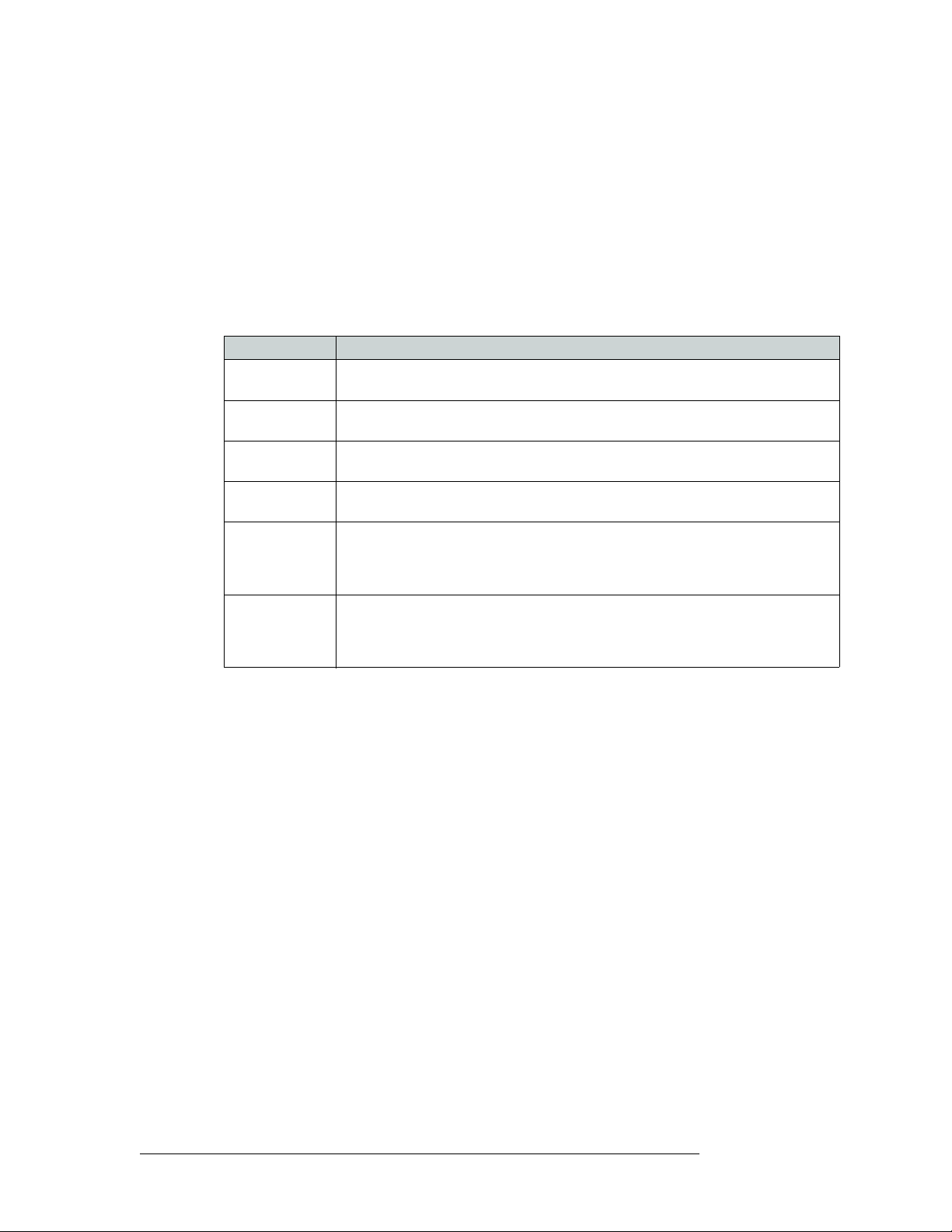
4. Configuration
Setting Jumpers and Switches on Cards and Card Sets
6 Close the router door.
Control Card Jumper Settings
The control card(s) (EM0374) contains several jumpers. Each jumper connection is labeled with a
jumper identification number. By default, jumpers are placed in the position most commonly used.
These jumpers must be set before the control card is placed into service.
The following lists each jumper label number, function, and correct setting. Any jumpers not listed
are unused and should be left in the factory position:
Jumper Label Settings
J1 SBUS/10B2 Sets rear connectors labeled 10Base2 to be used for Ethernet. Default set to lower
10Base2 position.
J2 SBUS/10B2 Sets rear connectors labeled 10Base2 to be used for Ethernet.Default set to lower
10Base2 position.
J4 SMS7/SBUS Sets rear Node Bus connectors to be used for third-party router control systems. Default
J6 SMS7/SBUS Sets rear Node Bus connectors to be used third-party router control systems. Default set
J13 AES REF2 Sets the rear AES REF 2 input impedance to 110
J16 AES REF1 Sets the rear AES REF 1 input impedance to 110
set to upper position.
to upper position.
Upper position selects 110
selects 75
input is the last connection in an equipment chain.
Upper position selects 110 Ω for use with Phoenix rear connectors, the middle position
selects 75
input is the last connection in an equipment chain.
Ω for use with BNC rear connectors, or the lower position selects Hi-Z if this
Ω for use with BNC rear connectors, or the lower position selects Hi-Z if this
Ω, 75 Ω, or Hi-Z (high impedance).
Ω for use with Phoenix rear connectors, the middle position
Ω, 7 Ω, or Hi-Z (high impedance).
Classic SWB Card Set Jumpers
Classic SWB card sets (EM0395) automatically re-clock signals at 177, 270, 360, 540 or 1485 Mb/s.
If the data is at any other rate, the re-clocker automatically bypasses the signal, sending it to the
output without re-clocking it.
Individual output re-clockers on the Classic SWB card set can be selectively disabled and the signal
passed directly to the output. This can be done on an output-by-output basis using the UniConfig
application. For more information, see the UniConfig User’s Guide.
Jumper J21, located near the rear of the output module, under the mezzanine board, can be used to
configure the Classic SWB card set for DVB/ASI operation. The jumper (J21) is labeled DVB/ASI.
The default position is DISABLED, allowing normal SWB operation. When J21 is set to
ENABLED, the re-clockers are configured for DVB/ASI operation. In this mode, the re-clockers
ignore the 177
Mb/s sub-harmonic in the signal thereby re-clocking the signal correctly. When set
to DVB/ASI mode, the output re-clockers work properly with all standard SWB signals except
those at 177
Mb/s.
Standard SWB Jumpers
The SWB output cards (EM0463 and EM0465) each contain two jumpers. One jumper (J30) is
located near the front top edge of the board and is labeled RECLOCKER MODE. When the jumper
68 Rev 2.5 • 24 Sep 09
Page 79

4. Configuration
Setting Jumpers and Switches on Cards and Card Sets
is in the AUTO position, the output re-clocker automatically re-clocks signals at 177, 270, 360, 540
or 1485
Mb/s. If the data is at any other rate, the re-clocker ignores the jumper setting and automat-
ically bypass the signal, sending it to the output without re-clocking it.
When in AUTO mode, individual output re-clockers on SWB output cards can be selectively disabled and the signal passed directly to the output, ignoring the jumper setting. This can be done on
an output-by-output basis using the UniConfig application. For more information, see the UniConfig User’s Guide.
When the jumper is in the OFF position, all output re-clockers are bypassed and the signal sent
directly to the output. The primary use of this jumper is for factory testing; it is normally left in the
default AUTO position.
A second jumper (J25) is located above J30 and can be used to allow operation with DVB/ASI signals. The default position is DISABLED, allowing normal SWB operation at all accepted data
rates. When J25 is set to ENABLED, the re-clockers are configured for DVB/ASI operation and
work properly with all standard SWB signals except those at 177
Mb/s.
Machine Control Card Set Jumpers
The Machine Control card set (EM0482) has one jumper (J51). In the lower (default) position, the
card set functions as a 32-port standalone port card set (ports 1-32). If the port card set is plugged
into slot 13, it functions as ports 33-64. A module is usually plugged into slot 13 when another port
module is already plugged into slot 11. If the jumper is placed in the upper position, the port card
set functions as a single standalone 32-port module regardless of where it is installed in the frame.
Analog Audio Switches
Depending on the analog audio source equipment you are using, you might want to change several
setting on the analog audio input card (EM0585) and/or analog output card (EM0586). Options
include:
• Setting the gain of individual channels.
If you are using single-ended inputs, you can double the input level by choosing a +6dB switch
setting for those input channels.
• Activating mute detection.
• Setting operating levels to match facility production levels.
Individual Channel Gain
The analog audio input card (EM0585) has four 8-position DIP switch sets near the center of the
board that allow the gain of each channel to be increased by 6dB
labeled SW1, SW2, SW3, and SW5. (SW4 is elsewhere on the board.) Place the switch in the OFF
position for normal gain (0 dB
). Place the switch in the ON position for a gain of 6 dB. There are 32
switches, one for each channel, 1L, 1R, 2L, 2R, and so on up to 16L and 16R.
These switches affect only input gain. The router output continues to operates with an effective
FSD of +24 dB
u. With the additional gain, source inputs are limited to +18 dB.
(doubled). These switches are
NV5128 Multi-Format Router • User’s Guide 69
Page 80

4. Configuration
Setting Jumpers and Switches on Cards and Card Sets
Mute Detection
The analog audio input card (EM0585) also has a mute detect enable jumper (J21), labeled ‘MUTE
CONTROL’. When the analog audio input level drops to –78 dB or lower for more than 0.25 per
second, the output sample values are replaced with digital silence. This jumper affects all inputs on
the card globally. The ‘ON’ position activates mute control; the ‘OFF’ position deactivates mute
control.
Figure 4-1 shows the location of the DIP switches for the analog audio input card (EM0585).
DIAGNOSTIC
OFF
Operating Level
DIAGNOSTIC
1
OFF
2
3
4
5
6
7
8
SW4
1
2
3
4
5
6
7
8
ON
ON
NV5128 ANALOG AUDIO 16 STEREO INPUT
EM0585-
NVISION
PC0639-00
INPUT CHANNEL GAIN
OdB
INPUT CHANNEL GAIN
+6dB
OdB
L
1
SW1
R
1
L
2
R
2
L
3
3
R
L
4
R
4
L
5
SW2
R
5
L
6
R
6
L
7
R
7
L
8
R
8
L
9
SW3
R
9
L
10
R
10
L
11
R
11
L
12
R
12
L
13
SW5
R
13
L
14
R
14
L
15
R
15
L
16
R
16
OFF
J21
ON
+6dB
L
1
SW1
R
1
L
2
R
2
L
3
3
R
L
4
R
4
Input Gain Control
SW2, SW3, SW5 similar
OFF
J21
ON
Mute Control
Figure 4-1. Analog Audio Input Card Switch and Jumper Locations
Operating Levels
Both the analog input card (EM0585) and the analog output card (EM0586) have an additional DIP
switch set that can be used to match the operating level of the facility. For example, if the incoming
signal operating level is +24 dbu, the card can be set to +24 dbu. By matching the incoming signal
level, there is less degradation of the signal when it is converted to digital for internal routing in the
router. Operating levels can be set for +15
70 Rev 2.5 • 24 Sep 09
dBu, +18 dBu or +24 dBu.
Page 81

4. Configuration
Setting Jumpers and Switches on Cards and Card Sets
The DIP is SW4 on the input card and S1 on the output card. Only the first two switches on the DIP
are used for the operating level. The following shows the switch positions for each operating level:
Switch 1 Switch 2 Operating Level (Max)
Off — +24dBu
On Off +18 dBu
On On +15 dBu
By default, all switches are set to ‘OFF’ and the operating level set to +24
dBu.
Figure 4-2 shows the location of the DIP switches for analog audio output card (EM0586):
OFF
DIAGNOSTIC
S1
NV5128 ANALOG AUDIO 16 STEREO OUTPUT
1
ON
2
3
4
5
6
7
8
EM0586-
NVISION
PC0640-00
DIAGNOSTIC
OFF
Operating Level
1
2
3
4
5
6
7
8
ON
Figure 4-2. Analog Audio Output Card Switch Locations
Analog Video Conversion (AVC) Card Switches
The AVC input card (EM0432) receives incoming composite analog video (NTSC or PAL) and
converts the signal to SD format for delivery to the motherboard. The AVC output card (EM0433),
receives SD formatted signals from the motherboard and converts them to composite analog video
outputs in NTSC or PAL formats. Because the color space for SD signals differs from that of composite signals, the absence or presence of pedestal in NTSC signals must be accommodated if color
and luminance information is to be maintained. To accommodate these differences, DIP switches
NV5128 Multi-Format Router • User’s Guide 71
Page 82

4. Configuration
Setting Jumpers and Switches on Cards and Card Sets
are provided to preserve as best as possible the color and luminance integrity of signals processed
using AVC cards.
While composite PAL and NTSC inputs can be applied to and simultaneously routed by the AVC
input card (EM0432), all NTSC signals must be in the same format (NTSC-M or NTSC-J). The 8position DIP switch (S1) on the AVC input card configures the card to process NTSC signals correctly. If the incoming signals are NTSC-M formatted signals, set DIP Switch S1-1 to ON. The ON
position for S1-1 is determined by the markings on the body of the DIP switch. If the incoming format is NTSC-J (no pedestal), set S1-1 to OFF. The remaining seven switch positions (S1-2 through
S1-8) are not used. Switch S1-1 settings have no effect on PAL signal processing.
There are three 8-position DIP switches on the AVC output card (EM0433), labeled S1, S2 and S3.
Switch S2 is not used. The S1 and S3 switches (labeled ‘USER SETTINGS’) configure each output
for the correct NTSC output format (pedestal or no pedestal).
The AVC input card feeds NTSC signals to the AVC output card. All 16 outputs on each output
card must have pedestal settings that match the pedestal settings on the AVC input card. For example, if the input card’s S1-1 is set to ON, then the output card’s S1 and S2 must have all 16 switches
set to ON. Refer to the silk screen markings on the AVC output card to identify and set switches to
their proper positions. Do not use markings on the actual switch bodies.
Note Attempting to convert NTSC-M signals to NTSC-J signals or vice versa results in
large Chroma/Luma gain errors.
If signals fed to the AVC output card originate from SD input cards, then each output can be configured for pedestal or no pedestal (NTSC-M or NTSC-J) composite outputs. DIP switches S1 and S3
have no effect when handling PAL signals.
72 Rev 2.5 • 24 Sep 09
Page 83

5. Operation
Chapter 5 provides operating instructions for the NV5128. It presents the following topics:
• Overview
• NV9000 Router Control System
• Third-Party Router Control Systems
Overview
To use the NV5128 router, you need a router control system. The router control system provides an
interface for the operations and maintenance personnel. Through the router control system, signal
switching can be actively configured, reference inputs selected, partitions for organizing signal
switching created, and certain system functions monitored.
The NV5128 was designed to partner with the NV9000 or NV915 control system. However, the
routers are designed with a certain degree of flexibility and can be used with certain third-party
router control systems. For detailed information on using the NV9000 or NV915 control system,
see the associated User’s Guide. For information on using third-party router control systems, see
the third-party vendor literature and User Guide. You can also contact Miranda for more information on compatible control systems. (See Technical Support Contact Information
NV9000 Router Control System
on page iii.)
Most facilities require multi-level switching capability (audio follow video, for example) and intuitive device naming capabilities. The choice of control system dramatically affects how operators
use the NV5128 and the ease with which devices are accessed.
Miranda’s NV9000 and NV915 control systems provide a powerful and flexible approach to controlling Miranda equipment and third party equipment. The Miranda control systems are comprised
of software and hardware. The control system application runs on a server and can be loaded on a
primary server alone, or also on a secondary (redundant) server as a fail-over backup. Miranda control panels or third-party systems connected to the server can be used to manage the router and
other network equipment.
Miranda’s NV9000 control system offers the choice of several control surfaces, supports redundancy and facilitates easy expansion as routing needs change. The NV9000 control system is also
capable of interfacing with third-party signal routing equipment. Because of the variety of features,
capabilities and limitations of other manufacturers’ equipment, users are urged to work closely with
Miranda’s technical staff and with the supplier of the third-party equipment when integrating it into
an NV9000 control system.
NV5128 Multi-Format Router • User’s Guide 73
Page 84

5. Operation
Third-Party Router Control Systems
Third-Party Router Control Systems
NV5128 control cards use a default protocol. However, at the timing or ordering, a number of thirdparty control protocols can be installed upon request.
Miranda provides assistance to users wanting to configure Miranda products to function with thirdparty control systems. However, because Miranda does not manufacture or warrant control systems
from other vendors, we cannot guarantee overall performance or answer all possible configurationrelated questions. For assistance, contact the manufacturer of the control system in use.
In many cases, router features and functionality are limited when using a third-party control system. For example, the third-party system may not optimally manage mono routing, while the
NV9000 control system easily manages this function.
Please consult with Miranda if you are considering using a third-party interface to control an
NV5128 router. (See Technical Support Contact Information
on page iii.)
74 Rev 2.5 • 24 Sep 09
Page 85

6. Maintenance
Chapter 6 provides instructions regarding maintenance. It discusses the following topics:
• Routine Maintenance
• Fuse Replacement
• Indicator LEDs
• Air Flow
• Intake Filter Screen Cleaning
• Battery Replacement
• Troubleshooting
• Obtaining Service
Routine Maintenance
The NV5128 requires very little in the way of routine or preventative maintenance. Other than
cleaning the fan air intake filter, all that is required is periodic inspection of the system to make sure
no failures have occurred.
You might want to examine the system’s Indicator LEDs
operating normally and to make sure that air flow to the power supply fans is unobstructed.
Caution Only qualified service personnel should perform procedures in this section.
occasionally to ensure that the system is
Periodic Inspection
Periodically inspecting the NV5128 for signs of trouble is the best way to prevent unplanned outages. The following items will be helpful when performing this inspection.
Begin the inspection at the front of the frame. Open the door to the router and make these observations.
1 Check the +48VDC LEDs on the front of the PS6000 power supplies. An LED that is off or
very dim in brightness indicates a failed or failing supply.
2 Place your hand lightly across the air intakes on the front of the power supplies. Slight air
movement should be felt, indicating that the internal cooling fans are running. These fans run at
very low speed, so only slight air movement will be noticed. A flashlight may be used to verify
that the fan blades are rotating at the proper speed.
3 Look at each active card and verify that none of the red alarm LEDs are illuminated. Normally,
the green and/or amber LED's should be illuminated. Refer to Indicator LEDs
interpret the LED status indicators.
NV5128 Multi-Format Router • User’s Guide 75
on page 76 to
Page 86

6. Maintenance
Fuse Replacement
4 Look at the control card(s) and verify that the green and amber LED's are illuminated on the
active controller, and that the green LED is ON for the standby controller (if present). Verify
that the low battery LED is off on one or both control cards. Refer to Indicator LEDs
page 76 for a description of the various LEDs and their meaning.
5 Inspect the air intake filter located inside the door. If the filter is dirty or clogged, refer to the
next section for information on how to clean it.
6 Next, move around to the rear of the matrix frame. Ensure that there are no missing backplane
cover plates. Replace any missing cover plates to ensure proper cooling in the frame.
7 Place a hand near the air exhausts. Strong air pressure should be felt evenly across the entire
opening.
8 Check cable connectors for any sign of unseating.
9 Verify that one or both AC cords are firmly seated at both ends. Make sure that the spring bail
power cord retainers on the rear of the frame are in place.
Fuse Replacement
on
If a problem occurs on a card, the first thing to do is check the fuses.
Fuses are located on each of the router’s active cards. Each card features either a “fast blow” or a
fuse that can be reset (“slow blow”). If the card requires a large amount of power, the fuse is “fast
blow” and must be replaced if blown. If the fuse can be reset, reset the fuse by removing the card
from the frame and letting the card temperature cool down. When the fuse temperature reduces to a
safe operating temperature, the fuse automatically resets itself and the card can be reinstalled. The
following table lists the fuses on each card:
Card or Module Fuse Value
Power supply AC Line Fuse 8 amp, 5 × 20 mm, slow-blow
Control card 1 amp
Crosspoint card 1 amp
Input card 1 amp
Output card 1 amp
Monitor card 1 amp
Warning Dangerous voltages are present at the rear AC power connector and on the power
supply module. Take precautions to prevent electric shock: Do not touch exposed
wires or connecting pins.
Indicator LEDs
Indicator LEDs indicate whether AC power is present and if a card is operating normally. LEDs are
visible when the router front door is closed. In the following sections, LEDs are listed in the order
they appear on the cards, from top to bottom.
76 Rev 2.5 • 24 Sep 09
Page 87

6. Maintenance
Indicator LEDs
Indicator LEDs on Power Supplies
The five green LEDs on the front of the power supply modules indicate presence of the five +48
VDC outputs of the five branch circuits. All five LEDs should be lit at all times when AC power is
present. If any LED is off, either the power supply has failed or the branch circuit is shorted.
Indicator LEDs on Control Cards
The LEDs on the front of the control cards can be monitored to determine whether the card is operating normally. The meanings of the LED indicators are as follows:
LED Indicator Indicator Function
Red (alarm) Indicates a problem or fault. Check the external reference signals; if this does not
resolve the problem, call Miranda Technical Support (see Technical Support
Contact Information on page iii).
Red (low battery) Indicates the battery needs replacing. See Battery Replacement
Amber (active) Indicates the card is the active control card. On the reserve control card, this LED
should be OFF.
Green (health) Normally ON. Indicates the card is operating normally.
on page 78.
Indicator LEDs on Input and Output Cards
The LEDs on the front of the input and output cards can be monitored to determine whether the
cards are operating normally. The LEDs indicate the following:
LED Indicator Indicator Function
Red (alarm) Normally OFF. If it is lit, it indicates a problem; replace the card or call Miranda
Technical Support.
GREEN (Power) Normally ON. Indicates the card is operating normally and receiving power.
Three additional LEDs situated further back on the output card indicate the following:
LED Indicator Indicator Function
Amber (health) Normally ON. Indicates software has loaded and the card is operating normally.
Green (good
communication)
Red (bad
communication)
Normally ON. Indicates good communication with the control card.
Normally OFF. If lit, indicates that communication is not working properly with the
control card; the communication is “bad.”
Test Points
All active cards, except the control cards, feature power supply test points located in the same pattern along the lower portion of the front edge. This simplifies verification of power supply status.
Test points are provided only for voltages actually present on the module.
The matrix controller also provides front card edge mounted test points. These are in a slightly different pattern than the matrix modules, but are clearly labeled for function.
NV5128 Multi-Format Router • User’s Guide 77
Page 88

6. Maintenance
Air Flow
Air Flow
The NV5128 draws cooling air from the front of the router, through the door, and exhausts heated
air through the rear of the frame. The router must have the door properly installed and closed for
proper airflow through the chassis. For maximum air flow, regularly inspect router fans and filters.
Caution If airflow is impeded overheating may occur.
Fan Cleaning and Replacement
One plug-in fan tray containing cooling fans is located at the top of the router frame (when viewing
from the front). The tray can be removed for inspection or cleaning by opening the frame front
door, sliding the latches that hold the fan module in place, and pulling the module out of the frame.
If the fans become dusty or clogged with lint, use a vacuum or compressed air to clean the dust off.
Also check the openings at the back of the frame where air enters and exits to be sure dust and lint
have not accumulated.
The fan tray is easily replaced simply by sliding the tray out of the front of the frame and inserting
a new tray. The fans on the tray are held in place by four screws and a pluggable connector. To
replace the fans, remove the screws and unplug the connector.
Intake Filter Screen Cleaning
The intake filter is located on the front door assembly of the NV5128 Multi-Format Router. To
access the filter open the router door by releasing the two thumbscrew locks. Remove the upper
module brace by loosening the two ¼ turn screws, then slide the filter up and to the right to remove
it. This process may be easier if the entire door is removed by lifting it straight up while open.
The system can be operated safely with the door removed for short periods of time. If the filter is
only lightly contaminated with debris, a vacuum cleaner or compressed air may be used for cleaning purposes. Clean the filter by vacuuming up loose debris or by blowing air from the clean side to
the dirty side. For filters badly loaded with debris, rinse with cold water or wash with warm water
and mild detergent. Be sure the filter is completely dry before re-installing it.
Battery Replacement
If the red Low Battery indicator on the control card turns on, the battery located on the front edge of
the card needs replacing. Grasp the exposed edge of the battery with your fingers and pull it
towards you to remove it.
Call
Miranda for replacement battery information. For contact information, see Technical Support
Contact Information on page iii.
78 Rev 2.5 • 24 Sep 09
Page 89

When you insert the new battery, be careful to observe the correct polarity.
Caution To prevent explosion of the battery and possible equipment damage or harm to
Replacing Modules
Active cards, power supply modules and backplanes can be replaced or reconfigured in the router
frame. Whenever reconfiguring, be sure each active card has the correct corresponding backplane.
Active Cards and Power Supply Modules
All front-loaded active cards and the power supply modules (PS6000) may be removed or installed
with the power on (“hot swapped”). Prior to installing a replacement card, verify that user settings
are configured correctly. Cards that receive and process serial data from the control card will automatically configure themselves at power up. If a card appears to be defective, first try re-seating it
in the frame.
6. Maintenance
Replacing Modules
personnel, be sure the battery is oriented with the correct polarity. Polarity markings are visible on the card’s battery housing.
Caution When removing SWB output cards, be sure to remove the expansion output cards
Backplanes
All but the SWB input and output backplane and the SD input backplane are passive and may be
removed at any time. Use the same cautions as exercised with front-loaded modules. Be sure to
match backplanes to the corresponding front active cards. The backplanes housing BNC connectors
are especially easy to install in the wrong location because they look very similar. However, no
damage will normally occur from an unintentional mismatch.
SWB Input/Output and SD Input Backplanes
Unlike other backplanes, SWB input and output and SD input backplanes contain active circuitry.
Power to these modules is supplied by the associated active card installed in the front. To remove
one of these backplanes, first remove the front associated card containing the power supply circuitry.
Troubleshooting
(EM0465) before attempting to remove the main output card (EM0463). Otherwise, damage to the connector “wing” assembly on the main output card may
occur.
Many system troubles are caused by easily-corrected errors, such as poor quality or missing input
or reference signals, incorrect configuration, and so on. This section lists common problems and
their solutions in the most likely order of occurrence. Refer also to the Introduction
NV5128 Multi-Format Router • User’s Guide 79
on page 3 for an
Page 90

6. Maintenance
Obtaining Service
overview of the system and its major components. Try troubleshooting the system yourself, and if
you are not successful, call
In the event that a problem is caused by a bad circuit board, swapping the bad board with a replacement circuit board is the quickest solution. If you need to order replacement boards or other components, see Technical Support Contact Information
Symptom Possible Causes and Solutions
System not powering up. Verify that the power cord(s) are plugged into the frame and the AC power
One or a few PS6000 power
supply modules not
powering up or not
operating properly.
Intermittent signal on one or
two outputs.
Intermittent or missing
signals on all outputs.
Miranda Technical Support as explained near the front of this manual.
on page iii.
source. Use a voltmeter to verify the presence of power.
Check the AC line fuse on the power supply module. See Fuse Replacement
on page 76.
Check that the PS6000 is fully seated in the frame.
Reset the PS6000 by reseating it in the frame.
Check that all five green LEDs on the front of the power supply modules are
lit. If an LED is not lit, it indicates a branch circuit may be faulty, which could
affect only certain modules in the frame. Replace the power supply.
Check PS6000 fuses. See Fuse Replacement
Check input and output cable continuity.
Check AES Reference.
Check Video Reference.
Check cable terminations.
Possible bad card. Swap each card in the signal path with another card to see if
the problem moves with the card. If so, replace the card.
If all cables, terminations, and cards check out OK, call Technical Support.
(See
Technical Support Contact Information on page iii.)
Problems with the AES reference inputs could cause all inputs to operate
intermittently or not at all. Check the quality of the reference signals and their
cable connections.
Check the control card, which processes the references to produce sync. A
synchronous system requires an operational control card in order to pass
signals. An asynchronous system will operate in its last state even if the
control card is removed. Change over to the reserve control card to see if the
problem goes away.
Possible low voltage on power supply module. Check power test points on
power supply. Voltages at power supply test points may be slightly high in
lightly loaded systems. Replace the power supply if any test points indicate
low voltage.
on page 76.
Obtaining Service
For service advice, warranty exchange, warranty repair, or out-of-warranty repair:
1 Call Miranda Customer Support at the telephone number in the front of this manual under the
heading Technical Support Contact Information
will help you resolve any service issues.
2 If you need an exchange or repair,
Miranda will assign you a Return Material Authorization
(RMA) number. Do not return equipment without first receiving an RMA number.
uses the RMA to track receipt of the equipment and to record repair or replacement information.
For out-of-warranty equipment, the
Miranda Technical Support Engineer estimates the cost of
repair when you call and requests a purchase order payable to
80 Rev 2.5 • 24 Sep 09
on page iii. Our Customer Service Personnel
Miranda
Miranda.
Page 91

6. Maintenance
Obtaining Service
If repair or exchange is required, package the assembly in an antistatic bag and place it in a
shipping box with plenty of padding to prevent damage.
3 Address the package using the Shipping Address listed in the front of this manual under the
heading Technical Support Contact Information
at your company’s expense.
4 When repair or replacement of in-warranty equipment is complete, Miranda return ships the
items at our expense. For out-of-warranty equipment Miranda charges a shipping and handling
fee. The standard shipping method is Second Day.
on page iii, and ship the equipment to Miranda
For out-of-warranty service,
replacement.
Miranda will send your company an invoice following the repair or
NV5128 Multi-Format Router • User’s Guide 81
Page 92

6. Maintenance
Obtaining Service
82 Rev 2.5 • 24 Sep 09
Page 93

7. Technical Details
Chapter 7 provides electrical, video, audio, and mechanical specifications for the NV5128. It discusses these topics:
• Power Specifications (Internal, PS6000)
• Physical Specifications
• Environmental Specifications
• Audio Specifications
• Video Specifications
• Time Code Specifications
• Machine Control Specifications
Power Specifications (Internal, PS6000)
The following table provides power specifications for the NV5128 Multi-Format Router’s internal
power supplies (PS6000):
Specification Details
AC input 90–130 or 180–250 VAC, 50/60 Hz, Auto-ranging
AC fuses Power Supplies:
8A (part number HB0145-00), slow-blow; 90–130 V
6.3A (part number HB0031-00), slow-blow, 180–250V
AC connectors 2, IEC 320
AC power PS6000, 660 Watts, one IEC 320
AC power usage Note: Power is based on PS6000 modules and power consumption
dependent on number of cards installed.
425 Watts nominal (128×128 SD), power factor corrected.
550 Watts nominal (128×128 SWB), power factor corrected.
260 Watts nominal (128×128 Analog Video), power factor corrected.
500 Watts nominal (128×128 AVC), power factor corrected.
225 Watts nominal (128×128 Sync AES), power factor corrected
625 Watts nominal (128×128 Analog Audio), power factor corrected.
Regulatory UL listed and CE compliant
NV5128 Multi-Format Router • User’s Guide 83
Page 94

7. Technical Details
Physical Specifications
Physical Specifications
The following table provides physical specifications for the NV5128 Multi-Format Router:
Specification Details
Dimensions 8RU (13.97 inches, 354.8 mm) high
Weight 56 lbs (25.5 kg); 182 lbs (82.7 kg) fully loaded.
Mounting EIA 310-C, 19.0 inches (482.6mm)
Grounding terminal Copper, accepts 14–6 AWG
Modules and slots 8 input cards, 16 signals each,
Diagnostic Standard: SMPTE 207M, RS-422/RS-232, configurable.
Serial control Standard: SMPTE 207M, RS-422
Ethernet 10/100baseT, IEEE 802.3
GSC “Node Bus” Standard: proprietary, serial
Power supply alarm Connector: Phoenix, 3-pin
19.0 inches (482.6 mm) wide
18.0 inches (457.2 mm) deep
8 output cards, 16 signals each,
2 control cards (1 primary, 1 optional secondary),
1 fan module,
2 PS6000 power modules (1 required, 1 optional redundant).
Connectors: 2, DE9
Connectors: 4, DE9 (2 per control card)
Protocol: Miranda Ethernet protocol
Connectors: 2, RJ-45
Connectors: 2, BNC, loop-through, non-terminating pair.
Impedance: 75 Ω
Environmental Specifications
The following table provides environmental specifications for the NV5128 Multi-Format Router.
Specification Detail
Operating temperature 0 to 40°C.
Relative humidity 0 to 90%, non-condensing.
84 Rev 2.5 • 24 Sep 09
Page 95

Audio Specifications
The following table provides audio specifications for the NV5128 Multi-Format Router.
Specification Detail
Audio reference input Standard: AES3 or AES3-id (serial digital audio).
AES3 inputs and outputs Standard: AES3 (balanced digital audio).
AES3-id inputs and outputs Standard: AES3-id (unbalanced digital audio).
Analog audio inputs and
outputs
7. Technical Details
Audio Specifications
Sample rate: 48kHz.
Connectors: 2, BNC or Phoenix.
Impedance: 75 Ω or 110 Ω.
Input level: 0.5 Vpp to 2.0 Vpp.
Sample rate: synchronous 48kHz; asynchronous 32–96 kHz.
Connectors: Phoenix.
Impedance: 110Ω.
Input level: 200 mV to 10 Vpp.
Output level: 2 Vpp.
Sample rate: synchronous 48kHz; asynchronous 32–96 kHz.
Connector: BNC.
Impedance: 75
Input Level: 100 mV to 1.2 Vpp.
Standard: 24-bit at 48kHz (analog audio).
Sample rate: 48kHz.
Connector: DB25
Impedance: input > 20 kΩ, output 50Ω.
Input level: FSD, +15, +18 and +24 dBu.
Output level: FSD, +15, +18 and +24dBu, selectable +6 dB gain via
switch.
Frequency response: 20 Hz to 20 kHz ± 0.2 dB
THD: < 0.02% at +4 dBu at 1 kHz
IMD: < 0.5% (per SMPTE method using a 60Hz +12 dBu wave and a
7 kHz, 0 dBu, sine wave.
Noise: 95 dB below +24 dBu.
Inter-route delay: < 1 µS.
Input-to-output delay: < 1.2 mS
Crosstalk: –80 dB, worst case.
Insertion gain: ± 0.1 dB.
CMRR: > 75 dB from 60 Hz to 20 kHz.
Ω.
Video Specifications
The following table provides video specifications for the NV5128 Multi-Format Router:
Specification Detail
Video reference input Type: analog video reference.
Standard: PAL, NTSC, or tri-level sync.
Connector: loop-through, BNC.
Impedance: 75 Ω or Hi-Z (greater than 20 kΩ), not selectable.
Input Level: 0.5 Vpp to 2.0 Vpp.
Input Return Loss: ≥ 30 dB to 5MHz.
NV5128 Multi-Format Router • User’s Guide 85
Page 96

7. Technical Details
Video Specifications
Specification Detail
SD inputs and outputs Type: standard definition, serial digital video.
SWB (SD and HD) inputs and
outputs
Analog video inputs and
outputs
Standard: SMPTE 259M and 344M.
Data rates: Automatic reclocking at 143, 177, or 270 Mb/s or automatic
bypass.
Data rates: Pass-through at 10 Mb/s to 270Mb/s.
Connector: BNC.
Impedance: 75 Ω.
Cable equalization: 300 m Belden 1694A, or equivalent cable, at 270 Mb/s.
Router path: non-inverting.
Input and output return loss: > 15 dB, 5 to 270 MHz.
Output level: 800 mVpp ± 10%.
Output rise/fall time: 600 ps ± 10%.
Output overshoot: ≤ 10% of max amplitude.
Output alignment jitter: ≤ 0.2UIpp from 1.0 kHz to 27 MHz
Output timing jitter: ≤ 0.2UIpp from 10 Hz to 1.0 kHz
Type: high definition, serial digital video.
Standard: SMPTE 259M, 344M and 292M.
Data rate: Auto re-clocking at 143, 177, 270, 360, 540 Mb/s and 1.483 and
1.485 Gb/s or auto bypass.
Data rate: pass-through at 10 Mb/s to 1.5 Gb/s.
Connector: BNC.
Impedance: 75 Ω.
Cable equalization: 150 m Belden 1694A, 85 m Belden 1855A, or
equivalent cable, at 1.5 Gb/s.
Router path: non-inverting.
Output level: 800 mVpp ± 10%.
Input and output return loss: > 15dB, 5 MHz to 1.5 GHz.
Output rise/fall time: ≤ 270 ps.
Output overshoot: ≤ 10% of max amplitude.
Output alignment jitter: ≤ 0.2UIpp from 100 kHz to 150 MHz.
Output timing jitter: ≤ 1.0UIpp from 10 Hz to 100 kHz.
Type: Analog video./
Standard: NTSC, PAL.
Connector: BNC, impedance: 75 Ω.
Input return loss: > 45 dB to 6 MHz.
Output return loss: > 45 dB to 6 MHz.
Input level: 1 Vpp.
Output level: 1 Vpp, nominal.
Output DC offset: ±3mV, relative to backporch.
Input range: ±2 V.
Insertion loss: 0 dB ±0.1 dB, all inputs to any one output.
Frequency response: ±0.1 dB to 8 MHz.
Differential gain: < 0.1
dB.
Differential phase: < 0.1 degrees.
Tilt: < 0.2%.
Delay scatter: ±1.75 degrees any input to any output, ±1.5 degrees any input
to any output slot (16 outputs), ±1.0degrees any input to any single output.
Noise spectrum: > 80 dB with pedestal unweighted to 7 MHz.
CMRR: > 60 dB to 10 kHz.
Crosstalk: 57 dBrms, worst case (100% PAL color bars), 72dBrms, worst
case (single to adjacent crosstalk).
Output-to-output isolation: >40
dB.
86 Rev 2.5 • 24 Sep 09
Page 97

Specification Detail
Analog/digital video
conversion
Time Code Specifications
7. Technical Details
Time Code Specifications
Type: analog digital video.
Standard: NTSC, PAL analog composite video.
Connector: BNC, Impedance: 75 Ω.
Level: 1 Vpp, nominal.
Common mode range: ±2 Vpp.
Frequency response (input): ±0.5 dB to 5.5 MHz (luminance).
Frequency response (output): ±0.2 dB to 5.5 MHz (luminance).
Luma/chroma delay: < 12
Luma/chroma gain inequality: < 0.5dB.
Differential gain: < 0.3%.
Differential phase: < 0.3 degrees.
Pedestal (input): > 75 dB, unweighted.
Pedestal (output): > 75 dB, unweighted.
Ramp (input): > 50 dB, unweighted.
Ramp (output): > 62.5 dB, unweighted.
ns.
The following table provides time code specifications for the NV5128 Multi-Format Router:
Specification Detail
Time code reference input Type: 1 BNC, 1 Phoenix.
Standard: SMPTE 12M.
Connector: BNC terminating, Phoenix.
Data Rates: 1/30th to 80 times normal.
Impedance: 75 Ω or 110 Ω.
Time code inputs and outputs Type: longitudinal time code.
Standard: SMPTE 12M.
Connector: Phoenix.
Data Rates: 1/30th to 100 times normal.
Impedance: 600 Ω or Hi-Z (> 20 kΩ), not selectable.
Input Level: 100 mV to 10 Vpp.
Output Level: 2.0 Vpp.
Machine Control Specifications
The following table provides port machine specifications for the NV5128 Multi-Format Router:
Specification Detail
Machine control inputs and
outputs
Type: bidirectional, dynamically configured.
Standard: RS-422 (Optional RS-232), ANSI/SMPTE 207M.
Connector: RJ-45.
Data rates: up to 115.2 kb/s.
NV5128 Multi-Format Router • User’s Guide 87
Page 98

7. Technical Details
Machine Control Specifications
88 Rev 2.5 • 24 Sep 09
Page 99

8. Glossary
Chapter 8 is a glossary.
Glossary
Active Cards See Modules.
AES Audio Engineering Society, Inc., New York, www.aes.org.
AES/EBU (Audio Engineering Society/European Broadcasting Union) a professional serial interface for
transferring digital audio from CD and DVD players to amplifiers and TVs. AES/EBU is typically
used to transmit PCM and Dolby Digital 5.1, but is not tied to any sampling rate or audio standard.
AES3,
AES3-id
Analog Audio A signal where the instantaneous voltage is proportional to the diaphragm velocity at the micro-
Async AES,
Sync AES
AVC “Analog Video Conversion.” Miranda uses this abbreviation to describe a simple conversion tech-
Backplane Modular, rear-mounted assemblies containing the NV5128’s input and output connectors.
D/A Digital to analog
DC Direct Current
dBu Unit of audio level where 0dBu is 0.775
The AES routers support AES3-id and provide 75Ω BNC connectors. AES3-id uses 75Ω coaxial
cable up to 1000 meters. (AES3 uses 110Ω shielded twisted pair (STP) cable with XLR connectors
up to a distance of 100 meters.)
phone.
The term “Async AES” refers to an asynchronous AES-compliant audio signal, whereas “Sync
AES” refers to a synchronous AES signal with a data rate of 48
nals are unlocked (not synchronized). Switching between signals leads to unpredictable results.
nique used to create an SD digital output signal from a composite analog video input, or to describe
the means by which SD signal is coded into an analog composite video output signal. Path delay
and subcarrier phase may not be precisely maintained in an AVC conversion path within an
NV5128 frame. AVC coding provides a cost-effective method to provide feeds to picture monitors
without requiring an external conversion device. AVC modules are not a substitute for professionalgrade format converters.”
Vrm s.
kHz. A system where various sig-
DB25 A DB25 connector is the common 25-pin subminiature D connector. Most modern PCs use a
female DB25 connector for the printer parallel port connector.
DE9 Sometimes mistakenly referred to as a DB9 connector, a DE9 connector is the common 9-pin sub-
miniature D connector. The serial port of modern PCs employ a male DE9 connector.
Device As the term is used in a NV9000 system, a device is a grouping of input and output ports that define
a logical entity. (The logical entity does not have to be a real entity.) For example, a system might
have 3 levels: video, AES, and time code. A hypothetical device in this system is Camera 1, which
NV5128 Multi-Format Router • User’s Guide 89
Page 100

8. Glossary
Glossary
consists of video on input port 1 of the video router, AES on input port 5 of the AES router, and
time code on input port 8 of the time code router. (The NV5128 does presently include time-code
routers.)
EIA Electronic Industries Alliance. The EIA (until 1997 Electronic Industries Association) is a trade
organization for electronics manufacturers in the United States. EIA is accredited by the American
National Standards Institute (ANSI) to help develop standards on electronic components, consumer
electronics, electronic information, telecommunications, and Internet security.
ESD Electrostatic discharge
HD HD and HD-SDI are equivalent in Miranda terminology. An HD signal is a high definition, serial
digital interface video format that conforms to the SMPTE 292M standard.
Hot-Swappable
I/O Inputs and outputs are the physical connections (e.g., BNCs) on the back of the routing switcher.
Jumpers Jumpers are small, plastic sleeves that fit over a set of pins. The placement of the jumper either
LED Light Emitting Diode
Matrix 1. The rack-mounted NV5128 chassis or frame which contains the subassemblies (modules, back-
Module 1. In the NV5128, modules are electronic assemblies that plug into the matrix. Modules include but
Operator The term operator usually refers to users other than the system administrator. An operator is respon-
Physical Level In a Multi-Format Router system, a physical level is the same thing as a router. The idea is that mul-
A module that is “hot-swappable” can be safely removed and/or installed while power is applied to
the system.
The term “input port” is used interchangeably with “input” and the term “output port” is used interchangeably with “output.”
turns a function on or off, or reconfigure a function.
planes, power supplies, etc.) which comprise the NV5128.
2. An X-Y array of crosspoint switches, a crosspoint matrix.
are not limited to input, output and controller printed circuit boards also called active cards.
2. Any removable subassembly may be referred to as a module. NV5128 backplanes may occasionally be referred to as modules.
sible for making most of the routes.
tiple routers provide different “levels” on which to switch the signals of devices. Any particular
device might send or receive HD, SD, AES, time-code, or machine-code signals. A Multi-Format
Router switches one type, or level, of a device’s signal set.
Physically
Contiguous
Port A port is the physical connection on a router. In a Multi-Format Router system, a port can only be
Reference Signal
90 Rev 2.4 • 28 Mar 09
Matrix modules are said to be in physically contiguous slots in an NV5128 frame when both the
inputs and outputs associated with those slots are in numerical sequence. For example, input slots 5
and 6 are physically contiguous because inputs 1-16 and 17-32 are in numerical sequence. In the
same way, output slots 4 and 16 are contiguous because outputs 49-64 (slot 4) and 65-80 (slot 16)
are in numerical sequence.
an input port or an output port.
A timing signal used to synchronize events such as the switching of video signals during a specific
portion of the vertical interval. Reference signals are externally applied. In their absence, internally
generated signals are used to sustain operation.
 Loading...