

Page 1
Newton
MODULAR CONTROL SYSTEM
Instruction Manual
SOFTWARE VERSION 2.0
071823402
DECEMBER 2004
Page 2

Contacting Grass Valley
Region Voice Fax Address Web Site
North America (800) 547-8949
Support: 530-478-4148
Pacific Operations +852-2585-6688
Support: 852-2585-6579
U.K., Asia, Middle East +44 1753 218 777 +44 1753 218 757
France +33 1 45 29 73 00
Germany, Europe +49 6150 104 782 +49 6150 104 223
Copyright © Thomson Broadcast and Media Solutions All rights reserved.
Grass Valley Web Site
Sales: (530) 478-3347
Support: (530) 478-3181
+852-2802-2996
Grass Valley
P.O. Box 599000
Nevada City, CA 959597900 USA
www.thomsongrassvalley.com
The www
Online User Documentation
.thomsongrassvalley.com web site offers the following:
— Current versions of product catalogs, brochures,
data sheets, ordering guides, planning guides, manuals, and release notes
in .pdf format can be downloaded.
FAQ Database
— Solutions to problems and troubleshooting efforts can be
found by searching our Frequently Asked Questions (FAQ) database.
Software Downloads
— Software updates, drivers, and patches can be down-
loaded.
2 Newton Instruction Manual
Page 3

Contents
Preface
. . . . . . . . . . . . . . . . . . . . . . . . . . . . . . . . . . . . . . . . . . . . . . . . . . . . . . . . . . . . . . . . . . . . . 7
About This Manual . . . . . . . . . . . . . . . . . . . . . . . . . . . . . . . . . . . . . . . . . . . . . . . . . . . . . 7
Certifications and Compliances . . . . . . . . . . . . . . . . . . . . . . . . . . . . . . . . . . . . . . . . . . 9
FCC Emission Control . . . . . . . . . . . . . . . . . . . . . . . . . . . . . . . . . . . . . . . . . . . . . . . . 9
Canadian EMC Notice of Compliance . . . . . . . . . . . . . . . . . . . . . . . . . . . . . . . . . . . 9
EN55103-1/2 Class A Warning . . . . . . . . . . . . . . . . . . . . . . . . . . . . . . . . . . . . . . . . 10
Safety Certification . . . . . . . . . . . . . . . . . . . . . . . . . . . . . . . . . . . . . . . . . . . . . . . . . . 10
Safety Terms and Symbols. . . . . . . . . . . . . . . . . . . . . . . . . . . . . . . . . . . . . . . . . . . . . . 11
Terms in This Manual . . . . . . . . . . . . . . . . . . . . . . . . . . . . . . . . . . . . . . . . . . . . . . . . 11
Terms on the Product . . . . . . . . . . . . . . . . . . . . . . . . . . . . . . . . . . . . . . . . . . . . . . . . 11
Symbols on the Product . . . . . . . . . . . . . . . . . . . . . . . . . . . . . . . . . . . . . . . . . . . . . . 12
Warnings . . . . . . . . . . . . . . . . . . . . . . . . . . . . . . . . . . . . . . . . . . . . . . . . . . . . . . . . . . . . 12
Cautions . . . . . . . . . . . . . . . . . . . . . . . . . . . . . . . . . . . . . . . . . . . . . . . . . . . . . . . . . . . . . 13
Section 1 — Newton Overview
Introduction . . . . . . . . . . . . . . . . . . . . . . . . . . . . . . . . . . . . . . . . . . . . . . . . . . . . . . . . . . 15
Newton Control Panels . . . . . . . . . . . . . . . . . . . . . . . . . . . . . . . . . . . . . . . . . . . . . . . . 16
Newton Rack Mount Control Panel . . . . . . . . . . . . . . . . . . . . . . . . . . . . . . . . . . . . 16
NewtonPC Software Control Panel . . . . . . . . . . . . . . . . . . . . . . . . . . . . . . . . . . . . 17
Router Interface Option . . . . . . . . . . . . . . . . . . . . . . . . . . . . . . . . . . . . . . . . . . . . . . 17
NetConfig Application. . . . . . . . . . . . . . . . . . . . . . . . . . . . . . . . . . . . . . . . . . . . . . . . . 18
Newton Panel Configurator Plug-In Tool . . . . . . . . . . . . . . . . . . . . . . . . . . . . . . . 19
Using Newton . . . . . . . . . . . . . . . . . . . . . . . . . . . . . . . . . . . . . . . . . . . . . . . . . . . . . . . . 20
Newton System Components and Options. . . . . . . . . . . . . . . . . . . . . . . . . . . . . . . . 22
. . . . . . . . . . . . . . . . . . . . . . . . . . . . . . . . . . . . . . . . . . 15
Section 2 — Installation
System Requirements . . . . . . . . . . . . . . . . . . . . . . . . . . . . . . . . . . . . . . . . . . . . . . . . . . 23
Windows Platforms. . . . . . . . . . . . . . . . . . . . . . . . . . . . . . . . . . . . . . . . . . . . . . . . . . 23
Gecko and Kameleon System Requirements: . . . . . . . . . . . . . . . . . . . . . . . . . . . . 24
Router Interface Requirements . . . . . . . . . . . . . . . . . . . . . . . . . . . . . . . . . . . . . . . . 24
Newton Control Panel Application Installation. . . . . . . . . . . . . . . . . . . . . . . . . . . . 25
Installing NewtonPC Control Panel Application . . . . . . . . . . . . . . . . . . . . . . . . . 25
Shortcuts . . . . . . . . . . . . . . . . . . . . . . . . . . . . . . . . . . . . . . . . . . . . . . . . . . . . . . . . . . . 29
Monitor Settings For Viewing NewtonPC. . . . . . . . . . . . . . . . . . . . . . . . . . . . . . . 29
Enable Router Interface on NewtonPC . . . . . . . . . . . . . . . . . . . . . . . . . . . . . . . . . 30
Checking Software Version of Software Panel . . . . . . . . . . . . . . . . . . . . . . . . . . . 33
Updating Software . . . . . . . . . . . . . . . . . . . . . . . . . . . . . . . . . . . . . . . . . . . . . . . . . . 33
Newton Rack Mount Control Panel Installation . . . . . . . . . . . . . . . . . . . . . . . . . . . 34
Rack Mounting. . . . . . . . . . . . . . . . . . . . . . . . . . . . . . . . . . . . . . . . . . . . . . . . . . . . . . 34
Rear Connections. . . . . . . . . . . . . . . . . . . . . . . . . . . . . . . . . . . . . . . . . . . . . . . . . . . . 34
Installing Newton Rack Mount Control Panel Software . . . . . . . . . . . . . . . . . . . 34
Checking Software Version of Rack Mount Panel . . . . . . . . . . . . . . . . . . . . . . . . 35
Updating Software on Rack Mount Panel With NetConfig . . . . . . . . . . . . . . . . 35
Newton Instruction Manual 3
. . . . . . . . . . . . . . . . . . . . . . . . . . . . . . . . . . . . . . . . . . . . . . . . . 23
Page 4

Contents
Enable Router Interface on Rack Mount Panel. . . . . . . . . . . . . . . . . . . . . . . . . . . 36
Uninstalling Software . . . . . . . . . . . . . . . . . . . . . . . . . . . . . . . . . . . . . . . . . . . . . . . . . 36
Configuration . . . . . . . . . . . . . . . . . . . . . . . . . . . . . . . . . . . . . . . . . . . . . . . . . . . . . . . . 36
Section 3 — Configuration
Network and Operating Parameter Configuration. . . . . . . . . . . . . . . . . . . . . . . . . 37
Newton Rack Mount Panel Configuration . . . . . . . . . . . . . . . . . . . . . . . . . . . . . . 37
Set Rack Mount Panel IP Address . . . . . . . . . . . . . . . . . . . . . . . . . . . . . . . . . . . 39
Set Rack Mount Panel System Configuration. . . . . . . . . . . . . . . . . . . . . . . . . . 40
Set Rack Mount Network Configuration. . . . . . . . . . . . . . . . . . . . . . . . . . . . . . 41
Enable Router Interface on Rack Mount Panel. . . . . . . . . . . . . . . . . . . . . . . . . 42
Rack Mount Factory Defaults . . . . . . . . . . . . . . . . . . . . . . . . . . . . . . . . . . . . . . . 43
Panel Configuration. . . . . . . . . . . . . . . . . . . . . . . . . . . . . . . . . . . . . . . . . . . . . . . . . . . 44
Channel and Setup Definitions. . . . . . . . . . . . . . . . . . . . . . . . . . . . . . . . . . . . . . . . 44
Configuring Channels and Setups . . . . . . . . . . . . . . . . . . . . . . . . . . . . . . . . . . . . . 44
Newton Panel Configurator Operation Overview. . . . . . . . . . . . . . . . . . . . . . 44
Creating A Configuration . . . . . . . . . . . . . . . . . . . . . . . . . . . . . . . . . . . . . . . . . . 56
Router Interface Option Configuration . . . . . . . . . . . . . . . . . . . . . . . . . . . . . . . 63
Soft Key Functions and Assignments. . . . . . . . . . . . . . . . . . . . . . . . . . . . . . . . . 65
Save Configuration to File . . . . . . . . . . . . . . . . . . . . . . . . . . . . . . . . . . . . . . . . . . 71
Download Configuration To Panel . . . . . . . . . . . . . . . . . . . . . . . . . . . . . . . . . . 72
Adding To or Revising A Configuration. . . . . . . . . . . . . . . . . . . . . . . . . . . . . . 75
Section 4 — Operation
Introduction. . . . . . . . . . . . . . . . . . . . . . . . . . . . . . . . . . . . . . . . . . . . . . . . . . . . . . . . . . 81
Overview . . . . . . . . . . . . . . . . . . . . . . . . . . . . . . . . . . . . . . . . . . . . . . . . . . . . . . . . . . . . 81
Newton Panel Description . . . . . . . . . . . . . . . . . . . . . . . . . . . . . . . . . . . . . . . . . . . . . 82
Enable Button . . . . . . . . . . . . . . . . . . . . . . . . . . . . . . . . . . . . . . . . . . . . . . . . . . . . . . 83
Panel Knobs . . . . . . . . . . . . . . . . . . . . . . . . . . . . . . . . . . . . . . . . . . . . . . . . . . . . . . . . 83
Accelerate Button/Knob Function . . . . . . . . . . . . . . . . . . . . . . . . . . . . . . . . . . . 83
Knob LED Indicators . . . . . . . . . . . . . . . . . . . . . . . . . . . . . . . . . . . . . . . . . . . . . . 83
Identify Button . . . . . . . . . . . . . . . . . . . . . . . . . . . . . . . . . . . . . . . . . . . . . . . . . . . . . 84
Navigation Arrow Buttons . . . . . . . . . . . . . . . . . . . . . . . . . . . . . . . . . . . . . . . . . . . 85
Router Interface Operation . . . . . . . . . . . . . . . . . . . . . . . . . . . . . . . . . . . . . . . . . . . 86
Router LED. . . . . . . . . . . . . . . . . . . . . . . . . . . . . . . . . . . . . . . . . . . . . . . . . . . . . . . 86
Route Button . . . . . . . . . . . . . . . . . . . . . . . . . . . . . . . . . . . . . . . . . . . . . . . . . . . . . 86
Monitor Button . . . . . . . . . . . . . . . . . . . . . . . . . . . . . . . . . . . . . . . . . . . . . . . . . . . 92
Soft Key Operation . . . . . . . . . . . . . . . . . . . . . . . . . . . . . . . . . . . . . . . . . . . . . . . . . . 94
Learn/Recall Button(s). . . . . . . . . . . . . . . . . . . . . . . . . . . . . . . . . . . . . . . . . . . . . . . 95
Learn Button . . . . . . . . . . . . . . . . . . . . . . . . . . . . . . . . . . . . . . . . . . . . . . . . . . . . . 95
Soft Key Setup Assignment From Control Panel . . . . . . . . . . . . . . . . . . . . . . . 96
Soft Key Router Source Assignment From Control Panel. . . . . . . . . . . . . . . . 98
Soft Key Monitored Destination Assignment From Control Panel . . . . . . . 101
Upload Soft Key Assignments to Newton Panel Configurator . . . . . . . . . . 104
Recall Button . . . . . . . . . . . . . . . . . . . . . . . . . . . . . . . . . . . . . . . . . . . . . . . . . . . . . . 105
Setup Index Mode . . . . . . . . . . . . . . . . . . . . . . . . . . . . . . . . . . . . . . . . . . . . . . . . 105
Enable Soft Key (Recall) mode . . . . . . . . . . . . . . . . . . . . . . . . . . . . . . . . . . . . . 107
. . . . . . . . . . . . . . . . . . . . . . . . . . . . . . . . . . . . . . . . . . . . . . . . . . 81
. . . . . . . . . . . . . . . . . . . . . . . . . . . . . . . . . . . . . . . . . . . . . . 37
4 Newton Instruction Manual
Page 5

Contents
Appendix A — Specifications
. . . . . . . . . . . . . . . . . . . . . . . . . . . . . . . . . . . . . . . . . . 109
Appendix B — Updating 8900/2000NET Software
8900/2000NET Software Requirements. . . . . . . . . . . . . . . . . . . . . . . . . . . . . . . . . . 111
Acquiring and Installing 8900NET Software. . . . . . . . . . . . . . . . . . . . . . . . . . . . 111
Acquiring and Installing 2000NET Software. . . . . . . . . . . . . . . . . . . . . . . . . . . . 113
Index
. . . . . . . . . . . . . . . . . . . . . . . . . . . . . . . . . . . . . . . . . . . . . . . . . . . . . . . . . . . . . . . . . . . . . 115
. . . . . . . . . . . . . . . . . . . . 111
Newton Instruction Manual 5
Page 6

Contents
6 Newton Instruction Manual
Page 7

Preface
About This Manual
This manual provides installation, configuration, operation, and safety and
regulatory information for the Newton Modular Control system rack
mount and software control panels for controlling Gecko 8900 Series,
Kameleon 2000 Series modular products, and a Router Interface option.
Newton Instruction Manual 7
Page 8

Preface
8 Newton Instruction Manual
Page 9

Regulatory Notices
Certifications and Compliances
FCC Emission Control
This equipment has been tested and found to comply with the limits for a
Class A digital device, pursuant to Part 15 of the FCC Rules. These limits
are designed to provide reasonable protection against harmful interference
when the equipment is operated in a commercial environment. This equipment generates, uses, and can radiate radio frequency energy and, if not
installed and used in accordance with the instruction manual, may cause
harmful interference to radio communications. Operation of this equipment in a residential area is likely to cause harmful interference in which
case the user will be required to correct the interference at his own expense.
Changes or modifications not expressly approved by Grass Valley can
affect emission compliance and could void the user’s authority to operate
this equipment.
This device complies with Part 15 of the FCC Rules (E4 environment).
Operation is subject to the following two conditions: (1) This device may
not cause harmful interference, and (2) this device must accept any interference received, including interference that may cause undesirable operation.
Canadian EMC Notice of Compliance
This digital apparatus does not exceed the Class A limits for radio noise
emissions from digital apparatus set out in the Radio Interference Regulations of the Canadian Department of Communications.
Le présent appareil numérique n’emet pas de bruits radioélectriques
dépassant les limites applicables aux appareils numeriques de la classe A
préscrites dans le Règlement sur le brouillage radioélectrique édicte par le
ministère des Communications du Canada.
Newton Instruction Manual 9
Page 10

Regulatory Notices
EN55103-1/2 Class A Warning
Safety Certification
For products that comply with Class A. In a domestic environment this
product may cause radio interference in which case the user may be
required to take adequate measures.
This product has been evaluated for Electromagnetic Compatibility under
the EN 55103-1/2 standards for Emissions and Immunity and meets the
requirements for E4 environment.
This product’s components have been evaluated and meet the Safety Certification Standards listed in Table 1.
Table 1. Safety Certification Standards
Component Standard Designed/Tested for compliance with:
UL60950 Safety of Information Technology Equipment, including Elec-
IEC 60950 Safety of Information Technology Equipment, including Elec-
Newton-RM Control Panel
CAN/CSA C22.2
N0. 60950-00
BS EN60950-2000
trical Business Equipment (Third edition revision, 3/15/02)
trical Business Equipment (Third edition, 1999).
Safety of Information Technology Equipment, including Electrical Business Equipment.
10 Newton Instruction Manual
Page 11

Safety Summary
Read and follow the important safety information below, noting especially
those instructions related to risk of fire, electric shock or injury to persons.
Additional specific warnings not listed here may be found throughout the
manual.
WARNING Any instructions in this manual that require opening the equipment cover
or enclosure are for use by qualified service personnel only. To reduce the
risk of electric shock, do not perform any servicing other than that contained in the operating instructions unless you are qualified to do so.
Safety Terms and Symbols
Terms in This Manual
Terms on the Product
Safety-related statements may appear in this manual in the following form:
WARNING Warning statements identify conditions or practices that may result in per-
CAUTION Caution statements identify conditions or practices that may result in damage
The following terms may appear on the product:
DANGER
the marking.
WARNING
sible as you read the marking.
sonal injury or loss of life.
to equipment or other property, or which may cause equipment crucial to
your business environment to become temporarily non-operational.
— A personal injury hazard is immediately accessible as you read
— A personal injury hazard exists but is not immediately acces-
CAUTION
Newton Instruction Manual 11
— A hazard to property, product, and other equipment is present.
Page 12
Safety Summary
Symbols on the Product
The following symbols may appear on the product:
Indicates that dangerous high voltage is present within the
equipment enclosure that may be of sufficient magnitude to
constitute a risk of electric shock.
Indicates that user, operator or service technician should refer
to product manual(s) for important operating, maintenance,
or service instructions.
This is a prompt to note fuse rating when replacing fuse(s).
The fuse referenced in the text must be replaced with one
having the ratings indicated.
Warnings
Identifies a protective grounding terminal which must be connected to earth ground prior to making any other equipment
connections.
Identifies an external protective grounding terminal which
may be connected to earth ground as a supplement to an
internal grounding terminal.
Indicates that static sensitive components are present which
may be damaged by electrostatic discharge. Use anti-static
procedures, equipment and surfaces during servicing.
The following warning statements identify conditions or practices that can
result in personal injury or loss of life.
Dangerous voltage or current may be present
battery (if applicable) before removing protective panels, soldering, or
replacing components.
— Disconnect power and remove
Do not service alone
person capable of rendering first aid and resuscitation is present.
Remove jewelry
and other metallic objects.
Avoid exposed circuitry
circuitry when power is present.
12 Newton Instruction Manual
— Do not internally service this product unless another
— Prior to servicing, remove jewelry such as rings, watches,
— Do not touch exposed connections, components or
Page 13

Safety Summary
Use proper power cord
this product.
Ground product
earth ground.
Operate only with covers and enclosure panels in place
product when covers or enclosure panels are removed.
Use correct fuse
product.
Use only in dry environment
Use only in non-explosive environment
explosive atmosphere.
High leakage current may be present
before connecting power.
Dual power supplies may be present
cord into a separate branch circuit employing a separate service ground.
Disconnect both power supply cords prior to servicing.
Double pole neutral fusing
— Use only the power cord supplied or specified for
— Connect the grounding conductor of the power cord to
— Do not operate this
— Use only the fuse type and rating specified for this
— Do not operate in wet or damp conditions.
— Do not operate this product in an
— Earth connection of product is essential
— Be certain to plug each power supply
— Disconnect mains power prior to servicing.
Cautions
Use proper lift points
Avoid mechanical hazards
servicing.
The following caution statements identify conditions or practices that can
result in damage to equipment or other property
Use correct power source
that applies more than the voltage specified for the product.
Use correct voltage setting
plies, before applying power ensure that the each power supply is set to
match the power source.
Provide proper ventilation
ment ventilation in accordance with installation instructions.
Use anti-static procedures
may be damaged by electrostatic discharge. Use anti-static procedures,
equipment and surfaces during servicing.
— Do not use door latches to lift or move equipment.
— Allow all rotating devices to come to a stop before
— Do not operate this product from a power source
— If this product lacks auto-ranging power sup-
— To prevent product overheating, provide equip-
— Static sensitive components are present which
Newton Instruction Manual 13
Page 14

Safety Summary
Do not operate with suspected equipment failure
damage or equipment failure, have the equipment inspected by qualified
service personnel.
Ensure mains disconnect
of this equipment provide the means of disconnection. The socket outlet
must be installed near the equipment and must be easily accessible. Verify
that all mains power is disconnected before installing or removing power
supplies and/or options.
Route cable properly
likely to be damaged. Properly support heavy cable bundles to avoid connector damage.
Use correct power supply cords
meet all North American electrical codes. Operation of this equipment at
voltages exceeding 130 VAC requires power supply cords which comply
with NEMA configurations. International power cords, if provided, have
the approval of the country of use.
Use correct replacement battery
reduce the risk of explosion, check polarity and replace only with the same
or equivalent type recommended by manufacturer. Dispose of used batteries according to the manufacturer’s instructions.
— If mains switch is not provided, the power cord(s)
— Route power cords and other cables so that they ar not
— Power cords for this equipment, if provided,
— This product may contain batteries. To
— If you suspect product
Troubleshoot only to board level
populated with surface mount technology (SMT) components and application specific integrated circuits (ASICS). As a result, circuit board repair at
the component level is very difficult in the field, if not impossible. For warranty compliance, do not troubleshoot systems beyond the board level.
— Circuit boards in this product are densely
14 Newton Instruction Manual
Page 15

Newton Overview
Introduction
The Newton modular control system provides comprehensive and consolidated real-time control for Grass Valley modular and router products. Two
control panel designs give fast, multi-knob, Ethernet-based access in a
user-configured processing channel. A standard Ethernet TCP/IP communications interface and a standard XML data format provide complete
signal processing monitoring and control.
Processing channels can be customized by the user from any combination
of modules present in any Ethernet accessible Gecko or Kameleon frame.
Module parameters can then be adjusted from a rack-mounted control
panel or by using a software-based control panel with similar functionality
running on a standard Windows PC.
Section
1
This approach to modular control utilizes the separation of system-level
configuration tasks from operational ones. This minimizes the potential for
on-air mistakes and provides the ability to group products and controls
into a logical signal path that can be easily accessed and adjusted.
A Router Interface option also allows the Newton control system to interface to Grass Valley routers with Native or RCL protocols to provide simple
X-Y direct router control and module source chain control. Module parameters in the router source chain can be controlled by a Newton Control
Panel associated with a router destination. Newton can also be used to
directly control a router for all level takes to specified destinations.
The Newton system also includes the Grass Valley NetConfig™ software.
This application allows network-wide configuration of the control panels
with a configuration plug-in called Newton Panel Configurator. It also
allows you to set IP addresses and update software from a single network
location.
The Gecko and Kameleon product lines also support the Grass Valley NetCentral application for Simple Network Management Protocol (SNMP) to
help maximize system support and uptime. NetCentral offers continuous
monitoring and user-programmable alerts in the event of equipment problems or signal loss.
Newton Instruction Manual 15
Page 16
Section 1 — Newton Overview
Newton Control Panels
The Newton system features two control panels: a rack-mounted version
and a software-based PC version. The NewtonPC software panel application has similar functionality as the rack mount panel, making operation
easier to learn. Any combination and number of panels can be used in a network; there is no limit to the number of panels that can be installed on the
network. Panel operation is independent of configuration and an
button is provided for locking out the panels to prevent accidental changes.
Overall control panel features include:
• Four user-configurable control knobs, with tri-color connection status
indicator LEDs, for changing device parameters,
•Twelve soft keys for quick recall of user-configurable parameters,
• Simple up/down, left/right navigation controls,
Enable
• Each panel supports up to 128 channels with 12 setups each (number of
channels allowed varies according to setup complexity),
•Clearly visible status of controlled devices,
•
•
button locally disconnects knobs and buttons from devices, and
Enable
Identify
button reveals identity of controls and configurations.
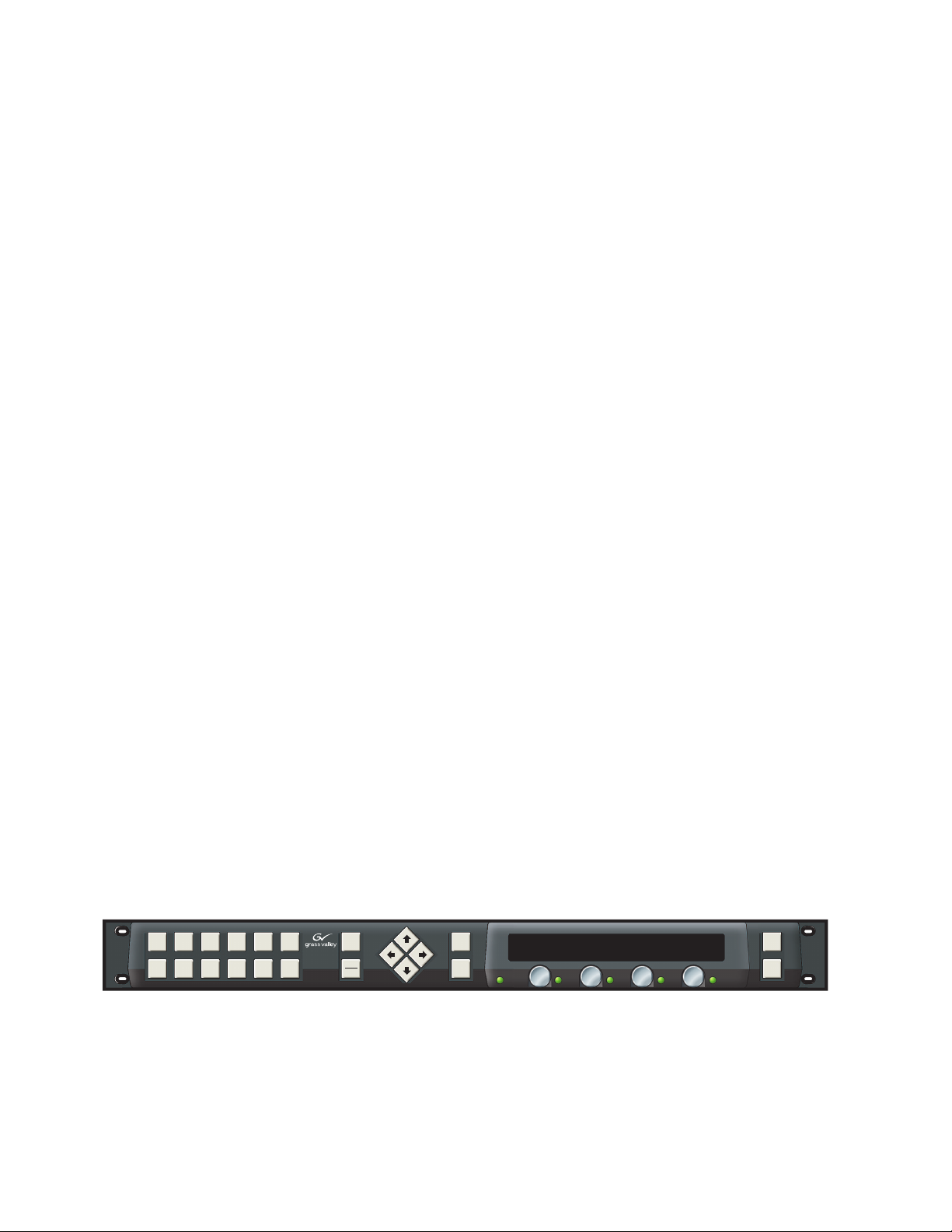
Newton Rack Mount Control Panel
The Newton rack mount control panel, NewtonRM, (Figure 1) is a compact, 1 RU Rack Mount panel.
Additional features of the rack mount control panel include:
• Easy to read green display with adjustable intensity,
•Combination of soft buttons and dedicated function buttons with
adjustable backlighting intensity, and
•Two simple connections required for installation, RJ-45 Ethernet and
IEC Mains.
Figure 1. Newton Control Panel
Video
Video
Audio
Master
Studio
Proc
Timing
Proc
Control
Sat
Sat
Sat
4
5
Sat
6
7
Edit
NEWTON
MODULAR CONTROL
Learn
Recall
Sat
Sat
8
9
Route
Mon
Router
vciGain1
100.0
vciGain2
100.0
vciGain3
100.0
vciGain4
100.0
Enable
Ident
16 Newton Instruction Manual
8234_00_01r1
Page 17
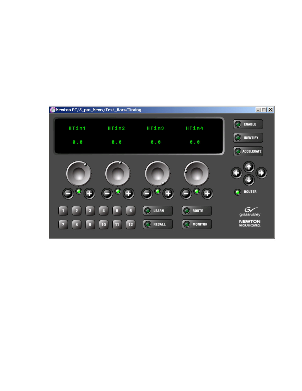
NewtonPC Software Control Panel
The NewtonPC software control panel (Figure 2) offers similar functionality to the rack mount control panel in a Windows-based PC software
panel application. Any PC on the network running the Newton software
panel application can configure and adjust processing channels.
Newton Control Panels
Note
Figure 2. Newton Software Control Panel with Router Interface
The software panel in Figure 2 is shown with the router interface option
enabled with a valid connection.
Router Interface Option
Both the rack mount and software control panels can operate with the
optional Router interface (NEWT-ROUTE). This option provides an interface to Grass Valley routers (see
for modular source chain control where the Newton Control Panel will
follow the router source selection on a monitored destination and simple
direct X-Y router control (change source and destination for all-level takes).
The
Route
panels when this option is enabled and a valid router connection is established. Soft keys can be configured to take router sources and to select
named router destinations.
Newton Instruction Manual 17
and
Monitor
buttons and the Router LED become active on both
Router Interface Requirements
on page 24)
Page 18
Section 1 — Newton Overview
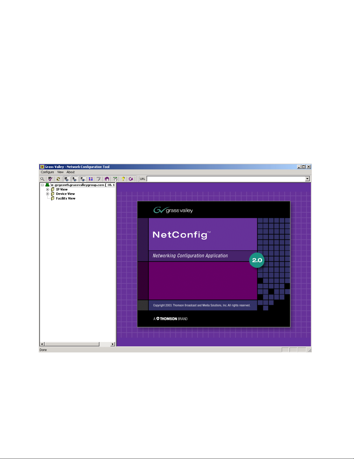
NetConfig Application
With the NetConfig application installed, in addition to using Newton
Panel Configurator required to configure the Newton panels, the PC can be
used to set IP addresses of panel and modular frame devices on the
network and update software to frame controllers and media modules
when updates become available. Because the NetConfig application runs
over the network, it centralizes and accelerates configuration tasks. It eliminates the need to physically visit every frame in the network, attach a
serial cable, and load parameters. Everything can be done from your
desktop. Refer to Figure 3 for an illustration of the NetConfig main view.
NetConfig also interfaces with many of the Grass Valley router control systems, and various other Grass Valley products.
Figure 3. NetConfig Main View
18 Newton Instruction Manual
Page 19
Newton Panel Configurator Plug-In Tool
The Newton Panel Configurator in NetConfig (Figure 4) is required for
panel configuration and is included on the CD. It provides an easy interface
for configuring a signal processing path—or channel—that includes an
individual module or a string of modules. Adjustable parameters or setups
can be defined for each channel. Each setup contains the assignments for
the four control knobs. Router sources can be associated with setups and
soft keys can be delegated to control router sources and destinations.
Configurable modules can be located on the network with NetConfig, then
dragged and dropped to the Newton Panel Configurator where specific
channels can be defined from the available parameters to provide any
number of setups for control with the four available knobs in each channel.
Figure 4. NetConfig with Newton Panel Configurator
NetConfig Application
Newton Instruction Manual 19
Page 20

Section 1 — Newton Overview
Using Newton
The Newton modular control system lets you quickly access all of the
Gecko and Kameleon modules in a signal processing path to make audio,
video, and timing adjustments from a single or multiple control points.
As an example of utilizing the Newton control system, an ideal real-time
application would be quality analysis and control of satellite and microwave incoming feeds. As shown in Figure 5 on page 21, the incoming satellite feed to a television station requires video analog-to-digital conversion
with processing and timing adjustments, along with multi-channel audio
processing and delay.
Using the NetConfig application and the Newton Panel Configurator, an
identifying name can be created for the processing channel that includes all
the modules in the path, such as SAT_4. The module icons can then be
dragged and dropped into the Newton Panel Configurator and the desired
parameters assigned to control knobs for the operator to adjust.
The SAT_4 channel in the example may have a number of adjustment
parameters that need to be controlled, such as video gain, black level, hue,
horizontal and vertical timing, audio levels and audio processing functions
such as sum, swap, and phase invert. These controls can be configured then
stored as nested setups which can be accessed when needed by navigating
through them using the Newton control panels.
The Newton control system recalls the current module parameters and displays them over each of the four control knobs. Each knob takes on the
functionality required for the parameter recalled. Parameters can be continuously variable (such as gain), or enumerated steps (such as an on/off control.)
Once the configuration of a control panel is complete, it can be saved to
offline storage, edited if required, and loaded to other control panels on the
network. This allows different operators to recall the setups they need for
the required broadcast or edit session.
For increased security, the Newton Panel Configurator allows the engineer
to specify the control available to each panel on the network. Access to a
frame, module, or set of parameters can be controlled.
In addition, with the Router Interface option enabled, simple X-Y control of
a configured router is possible from a panel. A panel can also be used to
follow the source selection from a router for parameter adjustment when
the source is taken to the Monitored Destination defined in Newton configuration.
20 Newton Instruction Manual
Page 21
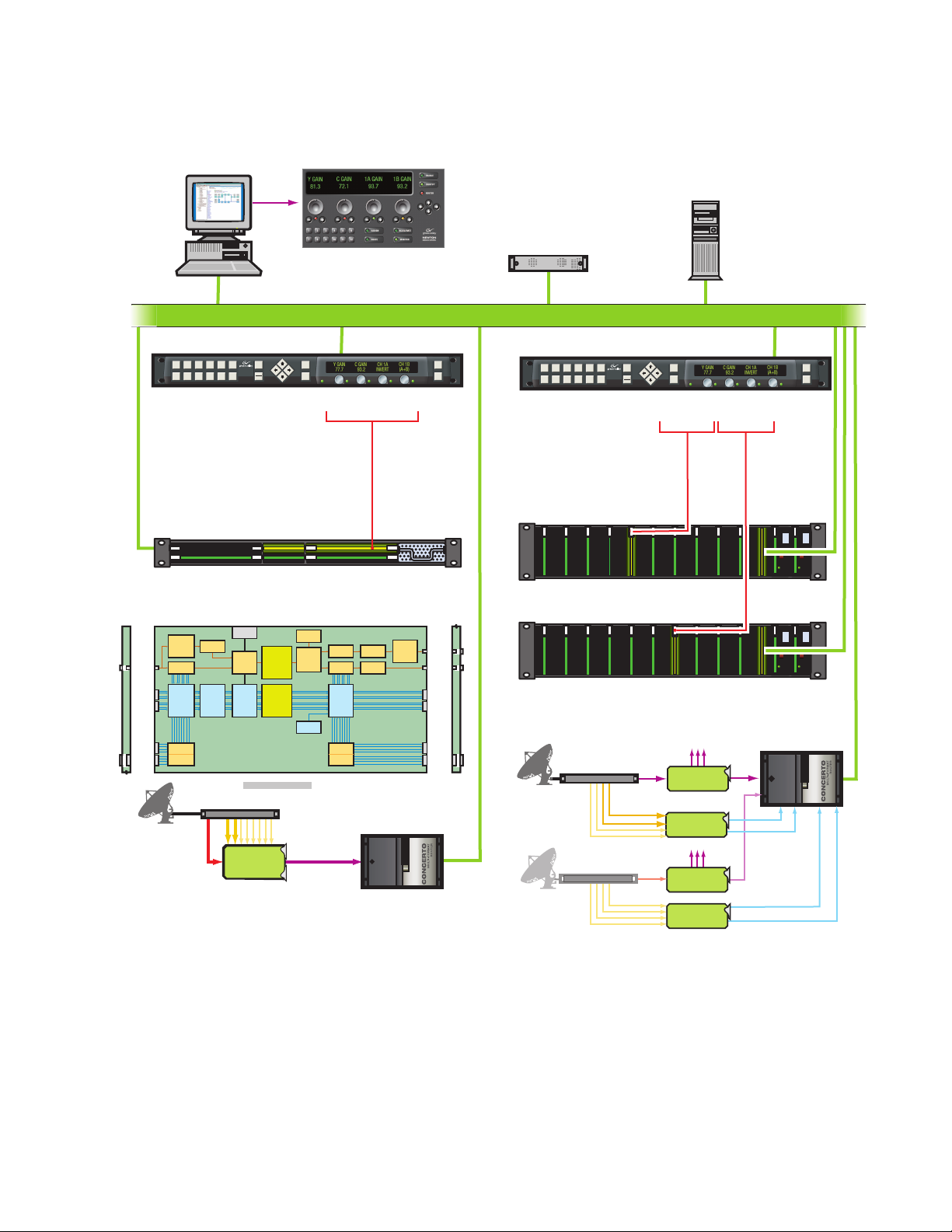
NetConfig with
Newton Control Extension
Figure 5. Newton Control Diagram
Newton Software
Control Panel
Encore Router Control
Ethernet Facility LAN
Using Newton
NetCentral
SNMP Monitoring
Newton Hardware Control Panel
Video
Video
Audio
Master
Studio
Proc
Sat
4
Kameleon Frame
Edit
Timing
Proc
Control
Sat
Sat
Sat
5
6
7
Learn
Sat
Sat
Recall
8
9
NEWTON
MODULAR CONTROL
Ethernet Interface
Kameleon Module Block Diagram
Frame
Video
Analog to
Digital
Converter
Composite
Demultiplexer Multiplexer
or SDI
Audio Select
Up to 4
and
AES Pairs
Sample Rate
(Balanced or
Converter
Unbalanced)
Passive Rear Module
Up to 8
Audio
Analog
Analog to
Audio
Digital
Channels
Converters
Analog
Video
Reference
Composite
Decoder
Frame
Processing
Synchronizer
Audio
Delay and
Tracking
Subsystem
8 x 8 Audio
Processing
Up to 4 AES Pairs Up to 4 AES Pairs
Audio
Channel
Pairing
IRD
KAM-AV
Route
Mon
Router
Kameleon Multi-Function
2000NET
Test Signal
Generator
Delay and
Video
Matrix
8 Ch Analog
Audio
VBI Control
Video/TSG
Select
Audio/TSG
Test Signal
Generator
Audio
Analog to
Digital
Converters
Embedded SDI
Module Control
Video
Digital to
Composite
Analog
Encoder
Converter
Delay and
VBI Control
Select
Concerto
Multi-Format Router
Enable
Ident
Composite
SDI
Up to 4
AES Pairs
(Balanced or
Unbalanced)
Up to 8
Analog
Audio
Channels
Passive Rear Module
Newton Hardware Control Panel
Video
Video
Audio
Master
Studio
Proc
Sat
4
Edit
Timing
Proc
Control
Sat
Sat
Sat
5
6
Learn
Sat
Sat
7
8
9
Recall
NEWTON
MODULAR CONTROL
Route
Mon
8960DEC
Control
Gecko Video Frame
8960DEC
Gecko Audio Frame
8921ADT
Analog
IRD
Sat 4
4 Ch Analog Audio
IRD
Sat 5
4 Ch Analog Audio
Video
8960DEC
Video A to D
8921ADT
4 Ch Audio A to D
8960DEC
Video A to D
8921ADT
4 Ch Audio A to D
Enable
Router
Ident
8921ADT
Control
8900NET
Ethernet
Interface
8900NET
Ethernet
Interface
Concerto
Multi-Format Router
Digital
Video
AES 1
AES 2
AES 1
AES 2
Newton Instruction Manual 21
Page 22

Section 1 — Newton Overview
Newton System Components and Options
Refer to Table 2 for a summary of the standard system components avail-
able with each Newton model and any options that can be purchased.
Table 2. Newton System Components and Options
Model Name Components
Newt-PC Software control panel application CD-ROM
NetConfig application
Newton Panel Configurator for NetConfig
Newton control panel application and system documentation in pdf format
Hard copy of Newton Control System Instruction Manual
Newt-RM 1 RU Rack Mount control panel
CD-ROM with:
NetConfig application
Newton Panel Configurator for NetConfig
Newton control panel application and system documentation in pdf format
Hard copy of Newton Control System Instruction Manual
Newt-Route
Newton Router Interface for use with Newt-PC or Newt-RM (requires acquisition of
License Key from Grass Valley)
22 Newton Instruction Manual
Page 23

Installation
This section contains the following installation information:
• System Requirements, including 8900NET module, 2000NET module
•NewtonPC installation for software panel, NetConfig application and
•1 RU Rack Mount Control Panel Installation, NetConfig application
•Router Interface option installation overview
Once installation is complete, each rack mount panel must be configured
for connection to the facility Ethernet. Then a panel configuration must be
created and downloaded to each panels as described in
Section 3-Configuration.
Section 2
and Router Interface option
Newton Panel Configurator
and Newton Panel Configurator
System Requirements
The NewtonPC software panel and NetConfig and Newton Panel Configurator run on a Windows platform and require the operating systems and
network interface software described below.
Windows Platforms
The Newton software panel and NetConfig applications can be installed on
the following Windows platforms on a networked PC:
•Windows 2000 with Support Pack 2.0
•Windows XP
Note To run NetConfig you must have Administrator privileges on the PC.
Newton Instruction Manual 23
Page 24

Section 2 — Installation
Gecko and Kameleon System Requirements:
Operation of the Newton Modular Control System requires the following
software for the Gecko 8900 and Kameleon 2000 Series systems:
Gecko 8900 series system requirements:
• 8900NET module with version 3.2.0 software or later
• Ethernet network connection
Kameleon 2000 series system requirements:
• 2000NET module with version 3.2.0 software or later
• Ethernet network connection
Software updates for the 8900NET and 2000NET modules can be obtained
by contacting Grass Valley Customer Service as described in
Appendix B-Updating 8900/2000NET Software.
Router Interface Requirements
The Newton Router Interface option will operate with the following
Thomson Grass Valley routing system protocols:
•Routers supporting RCL protocol
•Routers with Native Protocol and ethernet interface to system controllers
The Newton Router Interface option comes bundled with the latest software and is installed at the same time as the Newton panel software. It
must then be enabled by the user with a software License Key provided by
Grass Valley. Each device running the option (PC or rack mount panel)
must have a specific License Key based on the Device ID of the device it is
running on.
The Device ID from each device must be obtained in order to generate the
License Key. To obtain the Device ID, refer to the following page references
for each panel type:
•Newton PC Device ID (page 31)
•Rack Mount Panel Device ID (page 42)
Note Each License Key is node-locked. It will only enable the router interface on
the NewtonPC or rack mount panel whose Device ID was used to generate
the License Key. For installations with multiple NewtonPC applications on
multiple PCs or multiple rack mount panels, a License Key is required for
each separate application.
Refer also to the documentation that accompanies the option for more
information on how to obtain the License Key.
24 Newton Instruction Manual
Page 25
Newton Control Panel Application Installation
Newton Control Panel Application Installation
The NewtonPC software control panel application for the PC comes on a
CD-ROM along with the NetConfig networking tool and the Newton Panel
Configurator necessary for configuring panels.
Installation of the Newton software control panel is a process of installing:
•Newton Control Panel application,
•NetConfig Networking application, and
•Newton Panel Configurator.
These software components are all included in the install process.
Installing NewtonPC Control Panel Application
Install the NewtonPC Control Panel software and additional components
on a networked PC as follows:
1. Insert the NewtonPC CD-ROM into the CD drive in your networked
PC.
2. The setup application should autorun when inserted. If not, locate the
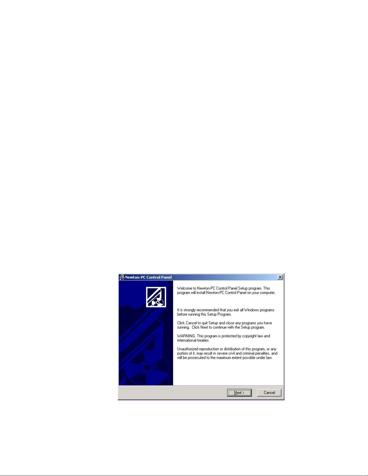
NewtonPC1-Setup.EXE file in the NewtonPC folder and double-click
on it to start the installation.
3. Read the Welcome screen and click on the Next > button (Figure 6).
Figure 6. Installation Welcome Screen
Newton Instruction Manual 25
Page 26
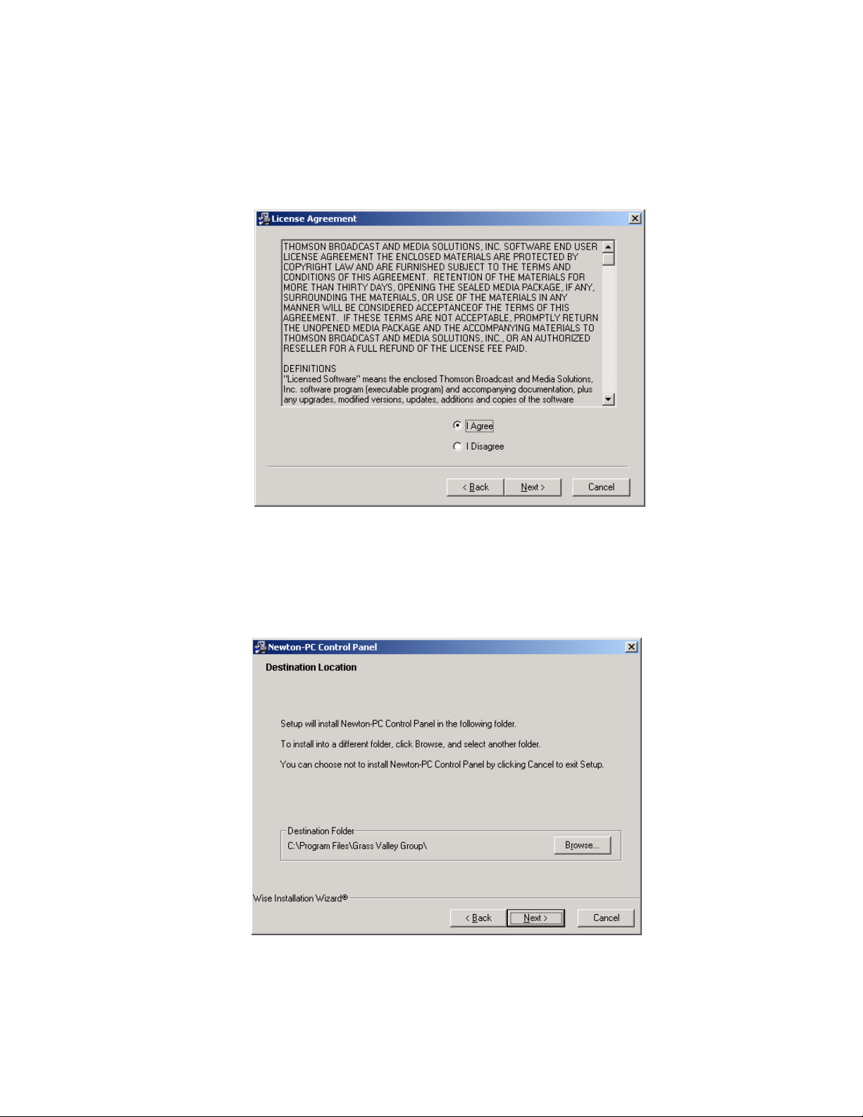
Section 2 — Installation
4. Read the license agreement (Figure 7) and click on the I Agree radio
button, then the
Next > button to continue.
Pressing the
Figure 7. License Agreement Screen
5. Select the destination location for installing the applications (Figure 8).
(The default is recommended.) Use the
folder. When finished, select the
I Disagree button will halt the install.
Browse button to select another
Next > button.
Figure 8. Installation Destination Location
26 Newton Instruction Manual
Page 27
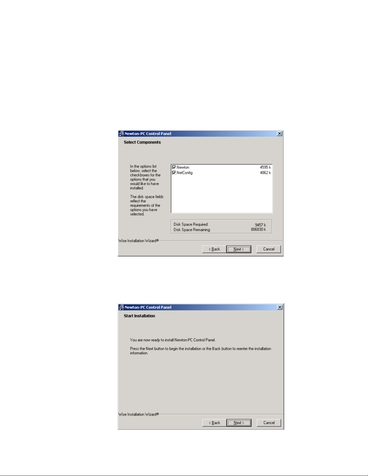
Newton Control Panel Application Installation
6. In the Select Components screen (Figure 9), select the Newton and
NetConfig checkboxes for every installation. NetConfig is required for
Newton panel configuration.
Note If you have an older version of NetConfig update to this version for proper
Newton configuration capability. Always update from the Newton CD to get
the latest released version of NetConfig.
7. Press the Next > button.
Figure 9. Installation Select Components Screen
8. In the Start screen (Figure 10), select the Next > button to begin the
installation.
Figure 10. Installation Start Screen
Newton Instruction Manual 27
Page 28
Section 2 — Installation
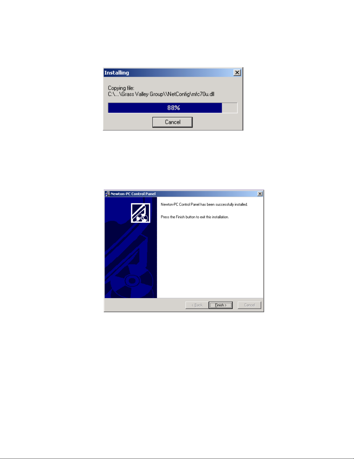
The Installing progress screen will be displayed (Figure 11).
Figure 11. Installation Progress Screen
Once installation is completed and successful, a Finish screen will be displayed (Figure 12).
9. Press the Finish > button to exit.
Figure 12. Installation Finish Screen
28 Newton Instruction Manual
Page 29

Newton Control Panel Application Installation
Shortcuts
Once software is loaded, a shortcut to NetConfig and NewtonPC will be
automatically installed on the PC desktop.
The NetConfig icon is illustrated at left.
The NewtonPC icon is illustrated at left.
Monitor Settings For Viewing NewtonPC
The following monitor settings are recommended for optimal viewing of
the NewtonPC software panel application:
•From the Windows Start menu, select Control Panels/Display/Advanced/Small Fonts
• Set the screen resolution to 1024 x 768 or higher
Newton Instruction Manual 29
Page 30
Section 2 — Installation
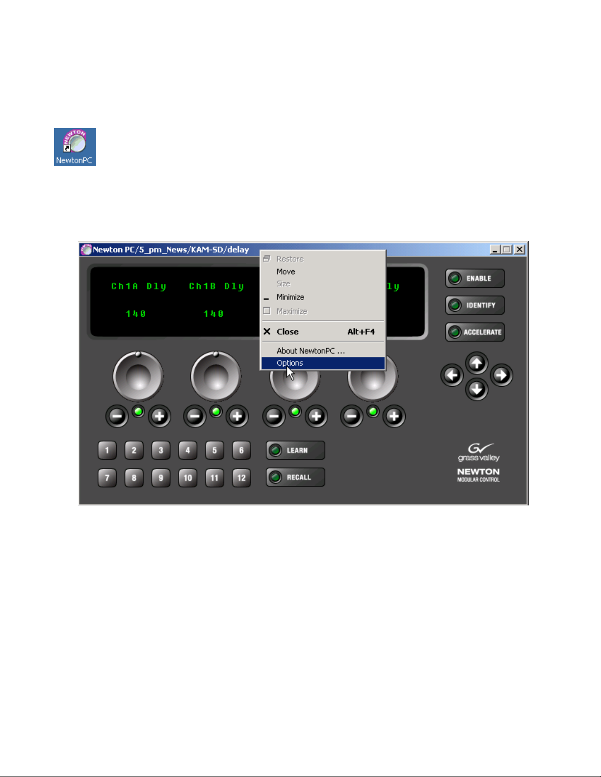
Enable Router Interface on NewtonPC
To enter the License Key to enable the option on the NewtonPC software
panel, do the following:
1. Open the application by double-clicking on the NewtonPC icon to
bring up the main application screen
2. Right-click on the blue bar at the top of the application to bring up the
pulldown menu shown in Figure 13.
3. Select the Options choice.
Figure 13. NewtonPC Router Interface Option Enable
30 Newton Instruction Manual
Page 31

Newton Control Panel Application Installation
4. A software License Key is required to enable the option. For
NewtonPC, you must first identify the Device ID on the PC on which
you will be using Newton to obtain this code. The Device ID is given on
the NewtonPC Options screen (Figure 14). Record this number and
contact Customer Service to obtain the License Key if you have not
been given this number already. Refer to Contacting Grass Valley on
page 2 for contact information.
Note When the Newt-Route option is ordered, a License Key form should accom-
pany the option when it is shipped. This document will also describe how to
obtain the License Key.
5. Enter the License Key code you have been given and select the Submit
button.
Figure 14. NewtonPC Options Screen
Device ID
A confirmation message will appear if the License Key was accepted and
the Router Interface Option will report
screen (Figure 14).
If an invalid code was entered, the message shown in Figure 15 will appear.
Figure 15. Invalid License Key Entered
Enabled on the NewtonPC Options
Newton Instruction Manual 31
Page 32

Section 2 — Installation
Once a router configuration is completed in the Newton Panel Configurator and downloaded to the soft panel, the
the Router LED will become visible as shown in Figure 16. Refer to Router
Interface Option Configuration on page 63.
For router operation, refer to Router Interface Operation on page 86.
Figure 16. Router Interface Option Enabled
Route and Monitor buttons and
32 Newton Instruction Manual
Page 33

Newton Control Panel Application Installation
Current software version
Checking Software Version of Software Panel
To check the currently loaded software version on the software panel, right
click on the blue bar at the top of the application to access the pulldown
menu and select the About NewtonPC selection (Figure 17).
Figure 17. NewtonPC Pulldown
This will bring up the screen shown in Figure 18. The current software
version loaded on this panel will be reported.
Figure 18. NewtonPC Software Version
Updating Software
NewtonPC software must be updated from a CD. Insert the updated CD
and install the latest NewtonPC and NetConfig over the old version.
License Keys entered for enabling the Router Interface option will be maintained and do not need to be re-entered.
Newton Instruction Manual 33
Page 34

Section 2 — Installation
Newton Rack Mount Control Panel Installation
Installation of the Newton 1 RU rack mount control panel is a process of:
•Rack mounting the panel,
•Making two simple rear connections: LAN and AC power, and
• Installing NetConfig software and Newton Panel Configurator.
Rack Mounting
The Newton rack mount panel is 1 RU high and designed to fit in a standard 19 inch equipment rack with customer-supplied rack mounting
screws.
Rear Connections
There are two rear connections to the Newton rack mount panel:
• IEC AC Mains – auto-sensing 90-260 VAC input, and
•LAN – a standard RJ-45 Ethernet connection.
Installing Newton Rack Mount Control Panel Software
The NewtonRM (1 RU Rack Mount panel) comes with a CD-ROM with the
Newton rack mount panel software along with the NetConfig networking
application and the Newton Panel Configurator necessary for configuring
panels.
Install the NewtonRM Control Panel software and additional components
on a networked PC in the same manner as the NewtonPC, following the
prompts given in the installation process. The installation process is the
same. Refer to Installing NewtonPC Control Panel Application on page 25 for
step-by-step instructions.
This installation will load the NetConfig application with the Newton
Panel Configurator and will place a NewtonRM folder in the destination
directory.
This NewtonRM folder contains a newton_APP.bin file that can be downloaded to a rack mount control panel for any necessary updates using NetConfig. This is only necessary when you have received updated software
on a CD or from the web site. The Newton rack mount control panel ships
from the factory with the latest software release. If you are installing a new
panel direct from the factory, there is no need to update the panel software,
unless you have been advised to do so.
34 Newton Instruction Manual
Page 35

Newton Rack Mount Control Panel Installation
Checking Software Version of Rack Mount Panel
To check the currently loaded software version on the rack mount panel,
hold down the
Ident button. The screen will shown the current software
version and the IP Address of the panel (Figure 19).
Figure 19. Software Version of Rack Mount Panel
V
In Gain
Video
Video
HTimg
Timing
Bright
Y OFF
Learn
Recall
NEWTON
MODULAR CONTROL
Route
Mon
Router
Newton Panel: SW Version 2.0.0
IP Address: 192.168.0.171
Updating Software on Rack Mount Panel With NetConfig
If you have received a CD with a NewtonRM update, use the following
procedure to install updated software to the rack mount control panel:
Enable
Ident
8234_00_11
Identify button
1. Open NetConfig and select the Load SW icon in the toolbar.
2. The Update Devices window will come up as shown in Figure 20.
The latest version of NewtonRM rack mount panel software should
appear in the Device Type list.
The Newton rack mount panels accessible on the NetConfig LAN will
appear in the Client Name list along with the software version currently installed and the IP Addresses of each device.
Figure 20. NetConfig Update Devices Window
Newton Instruction Manual 35
Page 36

Section 2 — Installation
Enable Router Interface on Rack Mount Panel
3. Highlight the Device Type of the software version you wish to update.
4. Check the box for the Newton rack mount panel to update in the Client
Name list. You may update any or all devices. Use the
to highlight all of the devices.
5. Check the Re-Boot when complete checkbox in the lower lefthand corner to
have the panel(s) re-boot when the software update is complete.
6. Click the Update button to begin the update.
7. Once all downloads are complete, use the Refresh button to update the
window and check that the version of software has been downloaded
to each selected device successfully.
8. When finished, select the Close button.
The Newton Router Interface option comes bundled with the latest software and is installed when the Newton Rack Mount Control Panel software is installed. It must be enabled by the user with a License Key code
provided by Grass Valley.
Select All button
To install the License Key code to active the option on the Newton rack
mount panel, refer to Enable Router Interface on Rack Mount Panel on page 42.
Uninstalling Software
To uninstall NewtonPC or NetConfig use the Windows Add/Remove Programs utility.
Note If a router option License Key has been enabled, it will not be deleted when
Configuration
This completes software installation for both software and rack mount
panels. Proceed to Section 3-Configuration for complete details on configuring and downloading configurations to the Newton panels.
the NewtonPC application is removed. Updating or installing new software
will maintain the License Key.
36 Newton Instruction Manual
Page 37

ConÞguration
This section describes configuration of the control panel for:
•Networking the panel(s) to the modules in your facility (setting IP
Addresses) and adjusting the rack mount panel operating parameters
(name, lamp intensity, Router option enable etc.),
•Defining channels and setups for module control by the panels, and
• Setting up soft key assignments for both channel setups and Newton
router interface functions.
Network and Operating Parameter Configuration
The first step in using either the rack mount or software panel is networking the panels to access the frames containing the 8900 and 2000
modules you wish to control. This is done by setting the Ethernet IP
Addresses to put the panels on the same subnet as the modular frames.
Section 3
Once the panel is connected to the network, you can then set the overall
panel operating parameters for lamp and display brightness etc.
Newton Rack Mount Panel Configuration
Once a rack mount panel has been installed and cabled, you will need to
configure it to the network where the modules to be controlled reside.
To access and configure a rack mount panel on the network:
1. Open NetConfig on the PC connected to the modular LAN where the
modules to be controlled reside. Your Newton rack mount panel should
be hard-wired to this LAN.
2. Select the Device View from the NetConfig toolbar (Figure 21 on page 38).
Expand the
LAN.
3. Expand the Module view to access the Newton rack mount panels.
Device View to see the Module and Router devices on the
Newton Instruction Manual 37
Page 38

Section 3 — Configuration
Discover Devices icon
4. Select the Discover Devices icon in the upper left corner of the window. All
Newton rack mount panels present on the network should be listed
under the Newton list.
Note Software panels are not seen in the tree structure.
5. Locate the Newton rack mount panel you want to configure. New
panels will appear with a red indicator dot, showing a default IP
Address.
6. Highlight the Newton rack mount panel name. The Newton Panel
Description page (Figure 21) will come up and display read-only
information about the panel. This page also provides links to other
panel pages.
Figure 21. Locating Newton Panels With NetConfig
IP, Device and
Facility icons
Device View
38 Newton Instruction Manual
Page 39

Set Rack Mount Panel IP Address
Before proceeding to the other links on the page, use NetConfig to set the
IP Address for this Newton panel as follows.
1. Select the Set IP Address icon in the Netconfig toolbar to set the IP
Address of this panel.
2. In the Change IP Address window, select Newton Panel in the Select
Device Type pulldown.
3. Double-click on the Newton panel in the list of devices that comes up
in NetConfig and enter the desired IP Addresses in the Change IP
Addresses box (Figure 22).
The default Subnet mask setting of 255.255.255.0 is recommended for a
Class C network, 255.0.0.0 for a Class A network. A Gateway IP
Address is only required if the local network uses a gateway to link to
an external network. Check with your system administrator for how to
set the IP Addresses to put this panel on the correct network.
4. Select OK to save this configuration.
Network and Operating Parameter Configuration
Figure 22. Change IP Addresses Box
Newton Instruction Manual 39
Page 40

Section 3 — Configuration
Set Rack Mount Panel System Configuration
Select the Panel System link on the left of the Newton Panel Description web
page to bring up the Newton Panel System Configuration web page
(Figure 23). The configuration will be the factory default values.
Figure 23. Newton Panel System Configuration Web Page
1. Type in the desired name for the panel in the Panel Device Name box.
2. Adjust the following parameters for the selected rack mount panel as
desired:
• Panel Blink Button Lamp Rate – currently not implemented.
• Panel Background Button Intensity – sets the LED intensity on the
panel for use in a dark environment.
• Panel Dim Button Intensity – currently not implemented.
• Panel Display Intensity – sets the brightness of the display.
• Panel Rotary Shaft Hysteresis – use this control to adjust the sensitivity and smoothness of the panel knobs if required.
• Panel Console Baud Rate – currently not implemented.
3. Select the Save New Settings button to save your changes or the Cancel
Changes to return to the previous values.
40 Newton Instruction Manual
Page 41

Network and Operating Parameter Configuration
Set Rack Mount Network Configuration
Select the Panel Network link on the left of the web page. This will bring up
the Newton Panel Network Configuration web page (Figure 24). The
current Ethernet IP, Subnet Mask IP and Gateway IP addresses set on
page 39 will be displayed.
Figure 24. Newton Panel Network Configuration Web Page
You can also use this web page to set the IP Addresses of the panel as follows:
1. Enter the desired IP addresses to put this device on the same LAN and
subnet as the modules you wish to control.
2. Check the Do reset box if you would like to force the panel to reset upon
saving and resume (reboot) using the new network settings.
3. Select Save New Settings to save the new IP addresses.
4. Select Cancel Changes to cancel any changes made and return to the
previous value.
5. Select Factory Defaults to return all IP values to the factory settings.
Note Returning to factory default IP Addresses will put the panel on a different
network and may cause loss of communication to the panel.
Newton Instruction Manual 41
Page 42

Section 3 — Configuration
Enable Router Interface on Rack Mount Panel
Select the Panel Options link to enable the Newton Router Interface option on
this rack mount panel. This will bring up the Newton Router Interface
Option web page (Figure 25).
A software License Key is required to enable the option. For a NewtonRM
panel shipped from the factory with the option, you will receive a License
Key form with the code you must enter to enable the option.
If you are updating a panel in the field and adding the option, you will
need to first update to version 2.0 software then acquire the Device ID of
the panel (Figure 25) in order to receive a License Key from the factory.
Record this number from the panel you wish to run the option on and
contact Customer Service to obtain the License Key. Refer to Contacting
Grass Valley on page 2 for contact information.
Note When the Newt-Route option is ordered, a License Key form should accom-
pany the option when it is shipped. describing how to obtain the License Key.
1. To enable the Router Interface option, select the Enter License Key button.
Figure 25. Newton Panel Options Web Page
Device ID
2. In the screen that comes up, enter the License Key code provided from
Grass Valley in the blank field and press the
Figure 26. Enter License Key
Submit button (Figure 26).
42 Newton Instruction Manual
Page 43

Rack Mount Factory Defaults
Select the Factory Default link to view a read-only listing of the factory
defaults that are set for the Newton panel at the factory and will appear if
the
Factory Defaults button is selected on the Panel Network web page
(Figure 27).
Figure 27. Newton Panel Factory Defaults Page
Network and Operating Parameter Configuration
Newton Instruction Manual 43
Page 44

Section 3 — Configuration
Panel Configuration
The overall concept of Newton operation is based on Engineering configuration of the knobs and soft key buttons on each panel. Once channels and
setups are defined, operators can use the navigation buttons and configurable soft keys to access the parameters. Before operation of a panel is possible, a panel configuration must be defined with NetConfig using the
Newton Panel Configurator, then sent to a panel on the network.
Configuration is usually performed by Engineering staff. Once the configuration process is planned and executed, panel setups can be utilized by
operators.
Channel and Setup Definitions
Creating a configuration for a Newton panel is accomplished with the
Newton Panel Configurator in NetConfig. To do this, you first name a
signal processing path—a channel—that includes an individual module or
a string of modules. Next, the adjustable parameters—setups—are defined
for each channel. Setups could include such thing as audio modes, video
processing, or timing. Each setup contains the assignment for each of the
four control knobs.
The channels with their defined setups are then saved to a configuration
which is downloaded to a panel. Each panel supports up to 128 channels
with 12 setups each.
Note The number of channels allowed varies according to setup complexity when
more than about 70 channels are used.
Configuring Channels and Setups
This section describes how to configure channels and setups for a Newton
Control Panel. It is divided into the following sections:
•Newton Panel Configurator Overview
•Creating a Configuration
• Soft Key Functions and Assignments
•Adding or Changing a Configuration
Newton Panel Configurator Operation Overview
This section provides a brief overview of each of the components in the
NetConfig Newton Panel Configurator for reference. Configuration is
explained step-by-step in Creating A Configuration on page 56. The Newton
Panel Configurator is divided into four main tabs, each described in this
section.
44 Newton Instruction Manual
Page 45

Panel Configuration
To use the Newton Panel Configurator, open NetConfig and select the Con-
figure Newton Panels icon in the toolbar. This will bring up the Newton Panel
Configurator screen (Figure 28).
De-select the icon to turn the Newton Panel Configurator off. If panels have
been configured previously, the last saved configuration will be loaded into
Newton Panel Configurator.
Note There are three different view settings available for the NetConfig toolbar:
Image and Text, Image Only, and Text Only. They are selected under the Configure pulldown, NetConfig options, Configuration Options, Tool Bar.
Figure 28. Newton Panel Configurator Screen
Configure Newton Panels icon
Newton Instruction Manual 45
Page 46

Section 3 — Configuration
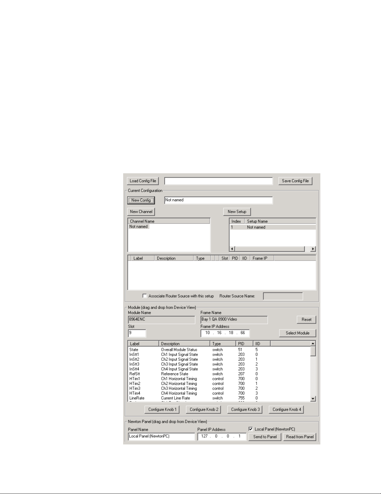
General Configuration Tab
The General Configuration tab contains the main setup controls for creating a configuration with the components described below.
•
Load Config File button– a previously saved configuration file can be
loaded into the Configurator for download to a panel. If you know the
location of the file, enter a path and filename into the box or select the
Load Config File button to bring up an Open dialog box (Figure 29).
In the Open dialog window, browse to a saved file and select it. Press
the
Open button to load this file into the Load Config File field.
Figure 29. Load Previously Saved Config File
46 Newton Instruction Manual
Page 47

Panel Configuration
The area labeled Current Configuration contains the following controls for
creating or editing a configuration:
•
New Config button – select this button to bring up a window (Figure 30)
to enter a name for a new configuration. Enter a First Channel Name
and First Setup Name for that configuration.
Note It is recommended to use standard PC naming conventions (no spaces,
forward or back slashes, or other characters that can create conflicts).
Figure 30. New Config Window
Newton Instruction Manual 47
Page 48

Section 3 — Configuration
• New Channel – select this button to name a new channel in the Enter
Name window (Figure 31). Select
in the Channel Name list under the
screen.
Figure 31. New Channel Window
Up to 128 channels are possible in a configuration. If the maximum
number of channels has been created, attempting to create another
channel will bring up the warning message shown in Figure 32.
OK when finished to enter the name
New Channel button on the main
Figure 32. Channel Limit Warning
48 Newton Instruction Manual
Page 49

Panel Configuration
• New Setup – select this button to name a new setup once a channel has
been defined above. The Enter Name window is identical to Figure 31
on page 48. Select
Name list under the
There is a limit of 12 setups per channel. If the maximum number of
setups are already created, attempting to create a setup will bring up
the warning message shown in Figure 33.
Note Creating complex setups can limit the number of channels that can be created
when using more than about 70 channels.
Figure 33. Setup Limit Warning
OK when finished to enter the name in the Setup
New Setup button on the main screen.
• Associate Router Source with this setup checkbox – when the Newton Router
Interface option is enabled, any setup can be associated with a router
source. When the router source is selected on the router, this setup will
automatically become active on the Newton control panel.
•
Router Source Name – a valid router source must be entered in the field
from the Router configured under the Router Configuration tab.
Newton Instruction Manual 49
Page 50

Section 3 — Configuration
Frame IP Address
The Module area shown in Figure 34 displays a selected module and its
published parameters available for configuring setups. Any media module
in an 8900 or 2000 frame that appears in the main tree structure on the left
can be selected and dragged to this window.
Note Not all modules will have configurable parameters.
Figure 34. Newton Module and Panel Areas
Module slot number
and name
Module area
50 Newton Instruction Manual
Page 51

Panel Configuration
Published parameters
for selected module
The following information about a module is displayed in the window
(Figure 35):
•
Module Name – displays the name of the module that has been dragged
and dropped into the parameter window.
• Frame Name – displays the name of the 8900 or 2000 frame containing
the selected module.
•
Slot Number – displays the slot number in the frame of the selected
module.
•
Frame IP Address – displays the IP Address of the frame containing the
displayed module.
A module can also accessed by entering the frame IP Address and module
slot number and clicking on the
Select Module button.
Use the
For example, the 8964DEC-FS module selected in the IP View in Figure 34
on page 50 can be dragged and dropped to the window where the param-
eters that are available from this module will be published (Figure 35).
Figure 35. Published Parameters In Module Window
Reset button to clear the parameter window.
Newton Instruction Manual 51
Page 52

Section 3 — Configuration
The published parameters include the following information:
•
Label – the name that will appear on the control panel display. (This
name can be changed by right-clicking on the control.)
•
Description – a description of the parameter from the module. Informa-
tion on what this control does on the module is available in the specific
module instruction manual.
•
Type – the type of control is either a variable control (such as gain) or a
switch (on or off).
•
PID and IID numbers – parameter and instance identifiers for software
development.
The order of the information columns for the parameters can be changed
by dragging a control to a different location as shown in Figure 36.
Figure 36. Changing Order of Parameter Information
Drag to change order
of column
Once a channel and a setup have been named, a parameter listed for the
module can be associated with a knob creating a setup using the following
controls:
•
Configure Knob 1-4 buttons – use the four Configure Knob buttons to select
the parameters to control from the module list published in the Module
window.
You may also right-click on a parameter in the list to assign a knob to a
control or switch. This process is explained in detail in Creating A Con-
figuration on page 56.
52 Newton Instruction Manual
Page 53

Panel Configuration
Panel IP AddressPanel Name
Read from Panel
button
Send to Panel
button
Local Panel checkbox
The Newton Panel area at the bottom of the Newton Panel Configurator
window shown in Figure 37 allows a configuration to be sent to, or read
from, a panel present on the LAN.
When a panel is dragged and dropped to the Newton Panel area, the following information about the panel is displayed:
•
Panel Name field– displays the name of the panel that has been dragged
and dropped into the parameter window.
•
Panel IP Address field – lists the IP Address of the displayed panel.
•
Send to Panel button – will download the current configuration to the
panel.
•
Read from Panel button – will upload the configuration from the panel in
the display to the Newton Panel Configurator.
•
Local Panel (NewtonPC) checkbox – checking this box will connect the
Newton Panel Configurator to the Newton software panel installed on
the resident PC running NetConfig. The IP Address shown is a loopback address from the local PC and should not be changed.
Figure 37. Newton Panel Area
Newton Instruction Manual 53
Page 54

Section 3 — Configuration
Router Configuration Tab
This tab in the Newton Panel Configurator (Figure 38) accesses the Router
Configuration interface. Newton will interface to a routing system with
either Native (with ethernet connection to MCPU or system controller) or
RCL protocols.
For a detailed description of router configuration refer to Router Interface
Option Configuration on page 63.
Figure 38. Router Configuration Tab
54 Newton Instruction Manual
Page 55

Panel Configuration
Soft Key Configuration Tab
The Soft Key Configuration tab (Figure 39) provides a method to assign soft
keys to recall channels and setups and/or router sources and destinations.
This process can also be performed locally at the panel. Refer to Soft Key
Functions and Assignments on page 65 for a more detailed explanation.
The following can be configured for each of the 12 soft keys:
•
Channel/Setup – select a channel from the current configuration, and
select a setup from the channel to assign to a soft key.
•
Router SRC on Monitored DST – a router source can be taken to the Moni-
tored Destination using a soft key.
•
Monitored Router DST – a Monitored Destination (the destination moni-
tored by the control panel) can be selected using a soft key.
Figure 39. Soft Key Configuration Tab
Newton Instruction Manual 55
Page 56

Section 3 — Configuration
Creating A Configuration
There are many ways to configure a Newton Control Panel, from a simple
configuration for one module to extremely complex ones involving many
modules. A configuration example is provided below to learn the concepts
for using the Newton Panel Configurator.
Use the procedure below to learn a sample panel configuration. This
example is based on setting controls for a single module with one channel
and four setups.
1. Open NetConfig and select the Configure Newton Panels button in the
toolbar to open the Newton Panel Configurator.
2. Select the New Config button in the Current Configuration area of the
General Configuration tab to bring up the Enter Names dialog box
(Figure 40 on page 57). Enter a name for the configuration. The
configuration name is used to summarize the functions of the
configuration or can be tied to the panel function itself.
For the example we will name the configuration 10pm_News.
56 Newton Instruction Manual
Page 57

Panel Configuration
3. Enter a name for the first channel and the first setup if known or leave
these boxes blank if the first channel and setup has not been
determined. Click on
Configuration area of the Newton Panel Configurator.
For the example we will use Sat_4 (Satellite 4) and Video Proc Input
Gains for the names.
Figure 40. Enter Names Dialog Box
OK to enter these names into the Current
Newton Instruction Manual 57
Page 58

Section 3 — Configuration
The channel in the example is going to contain various setups to control
the modules shown in Figure 41.
4. Locate a module in the tree structure on the left of the NetConfig screen
(Figure 41). In this case, we will use the 8964DEC quad decoder. This is
a module with four NTSC/PAL to SDI decoders.
5. Select the module and drag it to the lower window in the Module area.
This will publish the available control parameters on the 8964DEC to
the window as shown in Figure 41. Note that the
Name, Frame IP Address, and Slot fields in the Module area are now filled
in.
Figure 41. Dragging Module to Configure Knob Window
Module Name, Frame
Drag and drop module
58 Newton Instruction Manual
Page 59

Panel Configuration
Right-click on control for
knob choices
Highlight control then
select Configure Knob button
Knob 1 assignment
will be displayed
The first setup in the Sat_4 channel will assign the video composite
input gain controls for Channel 1 of the four decoders to the a knob on
the control panel.
6. Scroll down the Module parameter window and find nd select the
vciGain1 control (Figure 42).
7. Right-click anywhere on the highlighted control area to bring up the
knob menu or select the
assigns Knob 1 to control this parameter and places the
Configure Knob 1 button under the window. This
vciGain1
parameter information in the Current Configuration area.
Figure 42. Sample Configuration Example
Newton Instruction Manual 59
Page 60

Section 3 — Configuration
You can rename or delete the assignment that now appears in the
Current Configuration area by right-clicking anywhere on the highlighted control area and selecting
choosing
Figure 43. Rename or Delete Knob Assignment
8. Change the name of the vciGain control to Input_Gn_1.
9. Highlight the Input Video Gain vciGain2 control in the Module area and
associate it to the
Delete (Figure 43).
Configure Knob 2 button or right-click to bring up the
knob menu. Change the name to
Rename and entering a new name or
Input_Gn_2.
Label names have
been changed
10. Do the same for vciGain3 and vciGain4 controls associating them to
Knob 3 and Knob 4 respectively.
11. This will result in the Newton Panel Configurator screen as shown in
Figure 44. Note that the label names in the list have been renamed.
Figure 44. Sample Configuration Example – First Setup
60 Newton Instruction Manual
Page 61

Panel Configuration
12. Select the New Setup button to create the next setup in this channel. The
next setup will be called Video_Proc_Horiz_Timing in the example
(Figure 45).
Figure 45. New Setup Window
13. Now assign the four knobs in this setup to control the four available
Horizontal timing controls for each of the decoders on the module
simliar to the steps for the gain above.
14. Create a new setup for the vertical timing controls on each decoder.
15. Create a setup for the brightness/Y offset controls.
This creates a configuration with one channel and four setups for adjusting
Input Video Gains, Horizontal Timing, Video Timing, and
Brightness/Y Offset for each of the four decoders on the module.
Associate Router Source with Setup
When the Newton Router Interface option is enabled, any of the setups in
the channel created with the Newton Panel Configurator can be associated
with a router source. When that source is selected on the router, this setup
will be delegated automatically on the targeted Newton Control Panel(s) so
changes can be made with the control knobs. This is an aspect of the router
following and monitoring function.
This function is enabled by highlighting a setup then checking the
Router Source with this setup checkbox and entering a valid router source name
from the configured router in the
Note The router source name must be entered by the user and match a valid source
from the router source list.
Router Source Name field.
Associate
Newton Instruction Manual 61
Page 62

Section 3 — Configuration
Brightness/Y Offset setup
knob assignments
In the example shown in Figure 46, Setup 4, Brightness_Y Offset has been
associated with Router source, SRC_3 for the configured router. When this
source is selected on the router, and the
control panel, this Newton Control Panel will be delegated to this setup
and the controls can be adjusted using the control panel knobs assigned.
Any setup can be associated with a router source as long as the source
name matches a source in the router list.
Figure 46. Associate Router Source with Setup
Monitor button is selected on the
Associate setup with
router source.
62 Newton Instruction Manual
Page 63

Router Interface Option Configuration
To use the Newton Router Interface, first enable the option for the rack
mount (Enable Router Interface on Rack Mount Panel on page 42) and/or soft
panel (Enable Router Interface on NewtonPC on page 30).
In Newton Panel Configurator, select the Router Configuration tab, then
select the type of router connection to be used as one of the following:
None
If not using the router interface, select None and all fields will be grayed out,
Native Protocol
Enter the following for a Native Protocol connection (Figure 47):
•
Primary Router IP Address – enter the IP Address of the Primary MCPU in
this field.
•
Secondary Router IP Address – enter the IP Address of the Secondary MCPU
in this field.
Panel Configuration
•
Monitored Destination – enter the name of the destination to be monitored
by the Newton panels exactly as it appears on the router list.
•
Monitored Level – enter the router level to monitor for the destination (a
number between 1-64).
•
Destination Lock – selecting this checkbox locks the Monitored Destina-
tion from being changed from the panel.
Figure 47. Configure Router Interface – Native Protocol
Newton Instruction Manual 63
Page 64

Section 3 — Configuration
RCL Connection
Enter the following information for an RCL connection (Figure 48):
•
Primary Router IP Address – enter the IP Address of the Primary system
controller in this field.
•
Secondary Router IP Address – enter the IP Address of the Secondary system
controller in this field.
•
Router Area – enter the index number of the router area (a number
between 1-64).
•
Monitored Destination – enter the name of the destination to be monitored
by the Newton panels exactly as it appears on the router list.
•
Monitored Level – enter the router level to monitor for the destination (a
number between 1-32).
•
Destination Lock – selecting this checkbox locks the monitored destination
from being changed from the panel.
Figure 48. Configure Router Interface – RCL Connection
64 Newton Instruction Manual
Page 65

Soft Key Functions and Assignments
The twelve configurable soft keys on the left of the Newton rack mount and
software panel (Figure 49) operate in conjunction with the
buttons on the panel.
The
Recall button provides the following functionality:
•Recall Channel Setup – soft keys will recall user-assigned setups when
the
Recall button on the panel is on (enabled).
Panel Configuration
Learn and Recall
• Setup Index mode – when the
Recall button is off (disabled), the soft
keys will act as setup index keys. Refer to Soft Keys – Setup Index Mode
on page 68.
•Recall Router Source on Monitored DST – when the Router Interface
option is enabled and a valid router connection is configured, a soft key
can be assigned to take a named router source on the Monitored Destination.
•Recall Monitored Router Dst – when the Router Interface option is
enabled and a valid router connection is configured, a soft key can be
configured to select a Monitored Destination.
The router functions can be used in conjunction with saved setups to
allow setup recall and simultaneous router switching from one soft key
press.
Figure 49. Soft Keys on Panels
Soft Keys
Video
Video
Audio
Master
Studio
Proc
Timing
Proc
Control
Sat
Sat
Sat
4
5
Sat
6
7
Edit
NEWTON
MODULAR CONTROL
Learn
Recall
Sat
Sat
8
9
Route
Mon
Router
vciGain1
100.0
vciGain2
100.0
vciGain3
100.0
vciGain4
100.0
Enable
Ident
Newton Instruction Manual 65
8234_06
Page 66

Section 3 — Configuration
Soft Keys – Recall Channel Setup Mode
The assignment of soft keys for setup recall can be made from the Newton
Panel Configurator during the configuration process and sent to a panel or
made at a panel and sent back to the Newton Panel Configurator.
To delegate soft keys to specific setups using the Newton Panel Configurator:
1. Select the Soft Key Configuration tab in Newton Panel Configurator
(Figure 50 on page 67).
2. Select a Soft Key to be assigned by checking the corresponding
checkbox to activate the Soft Key functions. Soft Keys 1-4 are used for
this example.
3. From the Soft Key list, open the Soft Key 1 Channel pulldown and select
Sat_4.
Note In the Channel pulldown, the Sat_4 channel will be the only choice since this
configuration has only one channel.
4. In the Setup pulldown, select a setup from the list to assign to this soft
key. The Video_Proc_Input_Gains setup will be delegated to Soft Key 1
in this example.
5. Continue to delegate using Soft Keys 2, 3, and 4 for the example to the
Video_Proc_Horiz_Timing, Vertical_Timing, and Brightness_Y Offset
setups respectively as shown in Figure 50 on page 67.
6. When this configuration is saved and downloaded to a panel, Soft Keys
1-4 will bring up the corresponding setups when pressed and the
button is on.
Recall
66 Newton Instruction Manual
Page 67

Figure 50. Soft Key Channel/Setup Configuration Tab
Panel Configuration
Newton Instruction Manual 67
Page 68

Section 3 — Configuration
Soft Keys – Setup Index Mode
When the Recall button on a panel is off, the soft keys act as setup index
keys. Each soft key corresponds to a index number in the Setup list in the
Newton Panel Configurator.
For example, we have created more setups in the Sat_4 channel. Each setup
corresponds to an index number as shown in Figure 51. When the panel is
in Setup Index mode (
will display the corresponding setup in the panel display. Up to twelve
setups can be created in a channel, corresponding to the twelve soft keys.
On the rack mount panel, the soft keys that have corresponding setups
created in the Newton Panel Configurator will be low tally, those with no
corresponding setup will be off. This allows the user to view all of the
setups created in a channel while at the panel. It also allows them to see
what setups have not been made (soft keys lamps with tally off).
Figure 51. Soft Key Setup Index Example
Recall button off), selecting a soft key on the panel
Soft keys correspond
to the index number
of each setup present
in a channel.
68 Newton Instruction Manual
Page 69

Panel Configuration
Soft Keys – Recall Take Router Source
The soft keys can be utilized with the Newton Router Interface option to be
assigned to take specific router sources to the configured Monitor Destination in the Router Configuration tab.
To set up a router source to be recalled by a soft key, do the following:
1. In the Soft Key Configuration tab of Newton Panel Configurator, select
an unassigned soft key to recall a router source by checking the
SRC on Monitored DST checkbox in the corresponding soft key row to
activate the function. For this example, Soft Key 4 will be used
(Figure 52 on page 70).
2. In the blank enabled field, enter a valid source from the configured
router exactly as the source is named on the router list. The example
will use SRC_14.
3. This source will be taken to the currently selected Monitored
Destination when the
Recall button is on and Soft Key 4 is pressed.
Router
Soft Keys – Recall Select Monitored Router Destination
The soft keys can be utilized with the Newton Router Interface option to be
assigned to select a different monitored router destination than the one
configured in the Router Configuration tab.
To set up a router destination to be selected by a soft key, do the following:
1. In the Soft Key Configuration tab of Newton Panel Configurator, select
an unassigned soft key to select a monitored destination by checking
the
Monitored Router DST checkbox in the corresponding soft key row to
activate the function. For this example, Soft Key 5 will be used
(Figure 52 on page 70).
2. In the blank enabled field, enter a valid destination from the configured
router exactly as the destination is named on the router list. The
example will use D_DST_3.
3. When the Recall button is on and Soft Key 4 is pressed, the Monitored
Destination will be changed to the configured destination.
Soft Keys Summary
The three soft key controls can be set independently as explained in the
above examples or any of the three soft key controls can be configured to
the same soft key. This allows combining the recall of a channel setup,
taking of a router source, and selecting a specific destination in one key
press. This also allows router source/destination control with a single key
press if desired.
Newton Instruction Manual 69
Page 70

Section 3 — Configuration
Figure 52. Assign Soft Keys For Router Functions
Soft Key 4 assigned to
take router SRC_14.
Soft Key 5 assigned to select
router destination D_DST_3
for monitoring.
70 Newton Instruction Manual
Page 71

Save Configuration to File
After configuration is complete, the configuration can be saved to a file for
download to a panel and/or for recall at a later time.
1. Save this configuration to a file by selecting the Save Config File button in
the upper right corner of the screen (Figure 53).
Figure 53. Save Configuration File
Panel Configuration
2. This will bring up a Save As window similar to Figure 54. Enter the
name of the file to be saved, create a folder for saved files, and click the
Save button. All configuration files are saved in .xml format.
Figure 54. Configuration Save As Window
Newton Instruction Manual 71
Page 72

Section 3 — Configuration
Download Configuration To Panel
Use the Newton Panel area at the bottom of the Newton Panel Configurator
screen to send the configuration to a specific Newton Control Panel on the
network or a local software panel version of NewtonPC.
To send the configuration to a rack mount panel installed on the network:
1. Find the panel on the tree structure in NetConfig and drag and drop it
to the Newton Panel area at the bottom of the Newton Panel
Configurator screen. Panel Name and IP Address information will be
displayed for the remote panel (Figure 55).
2. Select the Send to Panel button to download to the networked panel.
Figure 55. Newton Panel Area with Rack Mount Panel
To send the configuration to a local software panel installed on the PC:
3. Select the Local Panel (NewtonPC) checkbox as illustrated in Figure 56. The
IP Address shown is a loopback address of the local PC on which it is
residing and should not be changed.
4. Select the Send to Panel button.
Figure 56. Newton Panel Area For Local Panel (Newt-PC)
5. When the Download OK message comes up, click OK in the NetConfig
download popup (Figure 57).
Figure 57. Download OK Popup
72 Newton Instruction Manual
Page 73

Panel Configuration
If a download failure occurs because of a target error (panel not found),
the software panel will display an error message (Figure 58).
Figure 58. Send to Panel Error
If the maximum configuration file size has been exceeded in the configuration being downloaded, the warning message in Figure 59 will appear. Size
of the configuration will vary according to the complexity of setups as a
function of memory size. If this message appears, the configuration can be
made smaller by deleting unused channels or setups or moving some channels to another configuration if necessary.
Figure 59. Configuration File Size Error Message
Newton Instruction Manual 73
Page 74

Section 3 — Configuration
For this example, a local NewtonPC Control Panel will be used to illustrate the configuration download and will appear similar to Figure 60.
Note that the channel and setup name now appear in the top line of the
software panel window in addition to the main display.
Figure 60. Local NewtonPC Loaded with Configuration
Downloaded channel and setup name
74 Newton Instruction Manual
Page 75

Adding To or Revising A Configuration
Configurations can be revised by adding channels and setups or revising
settings using the Newton Panel Configurator. Up to 128 channels each
with up to 12 setups (one for each soft key) can be created in a configuration
for download to a panel.
Note The number of channels allowed varies according to setup complexity when
more than about 70 channels are used.
Adding Channels
To add a channel to an existing configuration:
1. Load the configuration into the Newton Panel Configurator and select
the
New Channel button to bring up the Enter Name dialog box
(Figure 61).
For this example we will add a channel to 10pm_News for controlling
noise reduction with another module from the a different frame on the
network.
Panel Configuration
Figure 61. Add Channel to Configuration
2. Locate the module on the NetConfig tree structure and drag and drop
the module, the 8981NR in this example, to the Module area to publish
the available parameters.
3. Name a first setup for the channel by selecting the New Setup button.
Noise_Reduction will be used for the first setup in the example.
4. Assign parameters to each knob. In this case we will assign the two
noise threshold controls to Knobs 1 and 2.
5. Create two more setups for Y, R-Y, B-Y gains and offsets and make knob
assignments.
6. Save the configuration to the 10pm_News file and download it to the
local panel.
Newton Instruction Manual 75
Page 76

Section 3 — Configuration
The resulting configuration will now appear in the Newton Panel Configurator as shown in Figure 62. You can then assign soft keys to this channel
in the same manner as the first channel.
Figure 62. Channel Added to Configuration
76 Newton Instruction Manual
Page 77

Panel Configuration
The Newton local panel will now shown the additional Noise_Reduction
channel in addition to the first Sat 4 channel when scrolling through the
channels with the up and down arrow buttons (Figure 63).
Figure 63. New Channel on Newton Software Panel
Newton Instruction Manual 77
Page 78

Section 3 — Configuration
Revising Channels
To revise a channel:
Right-click on the channel name in the Channel List in the Current Configuration window to bring up the pulldown menu shown in Figure 64.
Figure 64. Revise Channel or Setup Pulldown
Use these functions in the pulldown to revise a currently defined channel:
•
Rename – brings up a dialog box to rename the channel.
•
Move Up or Down – move the channel name up or down in the Channel
Name list by selecting the Move Up or Move Down control or with the
arrow keys on the PC keyboard.
•
Copy/Paste Setup Names – copy the selected channel setup names and
paste them into a new channel. The knob assignments will not carry
over and will need to be assigned for the new channel.
For example, if we need another Decoder channel in the 10pm_News
configuration and would like to create the same setups as the Sat_4
channel, we can create a new channel and copy the setup names.
To do this, create a new channel, such as Sat_4_Decoder_2. Right click
on the Sat_4 channel and select
Right-click on the new Sat_4_Decoder_2 name in the list and select the
Paste Setup Names function (Figure 65 on page 79).
Copy Setup Names.
78 Newton Instruction Manual
Page 79

Figure 65. Copy and Paste Setup Names into New Channel
Panel Configuration
This will paste the setup names from the Sat_4 channel into the new
Sat 4_Decoder_2 channel. The corresponding controls from the new
module will now have to be assigned for each of these setups.
•
Delete – deletes the entire channel and all associated setups.
Adding or Revising Setups
Setups can be added or revised in a channel using the Configurator.
To add a setup to a channel:
1. With the configuration present in the Newton Panel Configurator
screen, highlight the channel to add the setup to and select the
button.
2. Name the setup and create knob assignments as desired with Newton
Panel Configurator.
Up to twelve setups can be present in a single channel.
To revise a setup:
You can rename a setup, reposition the name up or down in the setup list,
or delete a setup by right-clicking on the setup name in the Newton Panel
Configurator window to bring up the menu shown in Figure 64 on page 78.
New Setup
Save Configuration After Changes
After any changes, be sure to resave the new configuration to the
10pm_News file and download it to the panel again for changes to be
reflected on the panel.
Newton Instruction Manual 79
Page 80

Section 3 — Configuration
80 Newton Instruction Manual
Page 81

Operation
Introduction
Section 4
This section of the Newton Modular Control System is designed to explain
operation of the rack mount and software panels once they have been configured. Configuration of channels, setups, and knob assignments is done
using the Newton Panel Configurator in the NetConfig PC application. Soft
key setup assignments can be done during the configuration process with
the Newton Panel Configurator or from the panel itself as described in this
section.
Refer to Section 3-Configuration for compete details on how to configure a
Newton panel. This operation section will reference the same configuration
examples set up in Section 3.
Overview
Operation of the rack mount and software panels is similar. This operation
section covers both panel types and will point out the differences when
required.
Each Newton panel has four knobs and several buttons that form a control
surface. A configuration consists of channels containing setups. For each
defined setup, up to four knob assignments can be made which can control
a switch or parameter on a module. Setups can control any module that is
present on the network. Configuration of knob assignments can only be
done using the Newton Panel Configurator in the NetConfig application.
Newton panels allow you to navigate between channels and setups with
arrow buttons or using the configured soft keys on the panel.
To open the Newton software panel application, double-click on the
shortcut to the NewtonPC icon.
If no configuration has been downloaded to the software panel, the display
will report Setup not configured. You will need to download a configuration from the Newton Panel Configurator.
Newton Instruction Manual 81
Page 82

Section 4 — Operation
Newton Panel Description
A general overview of each component and its operation on the panel is
given below. Refer to the rack mount panel (Figure 66) and software panel
(Figure 67) illustrations.
Figure 66. Newton Rack Mount Panel Control Surface
V
In Gain
Video
Video
HTimg
Timing
Bright
Y OFF
User-defined soft keys
Not used
NEWTON
MODULAR CONTROL
Learn/Recall button
Route and Monitor buttons and LED
Route
Learn
Recall
Mon
Input_Gn_1
Router
Navigation buttons
Input_Gn_2
100.0
Configurable control knobs
Figure 67. Newton Software Panel Control Surface
Configurable control knobs Identify buttonAccelerate button
100.0
Input_Gn_3
100.0
Input_Gn_4
100.0
Enable button
Enable button
Enable
Ident
8234_00_04r2
Identify button
User Defined soft keys
Learn/Recall buttons
Route/Monitor buttons
82 Newton Instruction Manual
Navigation buttons
Page 83

Enable Button
Panel Knobs
Accelerate Button/Knob Function
Newton Panel Description
This button enables or disables the control panel surface communication
with the modules. When disabled (button tally off) rotating a knob or
pushing a button does not affect any modules. This prevents knobs from
being adjusted inadvertently causing unwanted parameter changes.
When enabled (high tally) the knobs will communicate with the modules
and adjust the assigned parameters.
The four configurable knobs on the panels control the currently displayed
parameters when the
to control specific parameters using the Newton Panel Configurator with
the NetConfig application.
Enable button is on (high tally). Knobs are configured
On the rack mount panel, pushing a knob in accelerates the adjustment by
ten times (multiplies the knob rotation by a factor of 10). The software panel
has an
tion of knob rotation.
The software panel also has
parameters.
Accelerate button that when enabled, performs the same multiplica-
Knob LED Indicators
Each knob has a tri-color LED associated with it to indicate to the user the
status of the associated parameter. The status of the parameter is indicated
by the following colors:
Green – module is communicating with panel.
Yellow – module configuration error such as parameter not found.
Red – failure to connect to module or temporarily disconnected.
The display will also indicate the error with text in place of the current
parameter (see Figure 66 on page 82 and Figure 67 on page 82).
Plus (+) and Minus (–) buttons for adjusting
Newton Instruction Manual 83
Page 84

Section 4 — Operation
Identify Button
When the Identify button is selected (high tally or LED on), selecting a
control on the display shows information about the panel controls and the
currently loaded configuration. This includes the function of each button,
the channel name, current setup name, soft key assignments, knob assignment information (if knob is configured) and parameters and ranges of
adjustment. Pushing the rack mount panel knob in while in this mode will
report the current knob configuration settings.
The example in Figure 68 illustrates the
ware panel with the
Figure 68. Identify Button Function
Learn button selected.
Identify button function on the soft-
On the rack mount panel, select the Ident button (high tally) and operate any
control to display its function or current configuration.
Holding the
version loaded on the rack mount panel and the panel IP Address.
84 Newton Instruction Manual
Ident button down will also display the current software
Page 85

Navigation Arrow Buttons
Four directional arrow buttons allow the user to scroll between channels
(up and down) and setups (left and right).
Each channel has a top level display indicating the name of the loaded configuration and the currently selected channel (Figure 69).
The left and right navigation arrow buttons will scroll through the setups
in that channel. The arrows will scroll through all setups in the channel,
returning to the top level Config and Channel name.
To scroll through channels in the configuration, use the up and down arrow
buttons.
Figure 69. Navigation Buttons – Software Panel
Currently loaded configuration and current top level channel
Newton Panel Description
Scroll through setups in
channel with right/left arrows
Scroll through channels in
configuration with up/down arrows
Newton Instruction Manual 85
Page 86

Section 4 — Operation
Router Interface Operation
The Router Interface option must be installed and enabled before the router
components will appear on the Newton PC control Panel (see Enable Router
Interface on NewtonPC on page 30) or become active on the rack mount
panel (see Enable Router Interface on Rack Mount Panel on page 42). Router
connection configuration for both panels is done using the Newton Panel
Configurator as described in Router Interface Option Configuration on
page 63.
The basic router functions available with this option are the following:
•Direct router control – provides simple X-Y router control for changing
sources and destinations for all-level takes, and
•Modular source chain control – provides router following and control
functionality where the Newton Control Panel will delegate (activate)
a setup when a particular router source is taken to the configured Monitored Destination.
Note A valid router configuration must be entered into Newton Panel Configurator
and downloaded to a panel before the router buttons and LED will be visible
on NewtonPC.
Router LED
Router connection status is indicated by the Router LED shown in
Figure 75 on page 90 (Newton PC) and Figure 76 on page 90 (Rack Mount
Panel).
The LED indicates the following router connection states:
•Off – router connection is not configured.
•Green – router is connected and reporting current status.
•Red – router is not connected.
Route Button
Using the Route button enables simple X-Y control of a router configured to
communicate with the Newton Control panel. Simple X-Y control allows
all level source takes to a single selectable destination.
The
•Pressing the
•The second press puts the display into the Monitored Destination select
Route button has three modes of operation as follows:
Route button the first time erases the status display and
places the display in Source/Destination select mode.
mode. This is the destination the Newton panels will follow in Monitor
mode. See Monitor Button on page 92.
•The third press restores the display to the normal operating mode and
turns off the green LED in the
86 Newton Instruction Manual
Route button.
Page 87

Newton Panel Description
Preset Source Select Mode
The first press of the Route button brings up the Preset Source select mode.
Preset Source select mode provides the means of taking a source using the
fourth control knob (indicated by a yellow LED) on a Newton panel. In this
mode, the current source on the selected destination is indicated at left as
shown in Figure 70 for the Newton PC software panel and Figure 71 for the
rack mount panel.
The Preset Source to be selected is indicated in brackets on the right of the
screen. This example shows SRC11 active on Dst1. Rotate the fourth knob
with the yellow LED (or use the
bring another source into the source preset brackets, in this case, SRC20.
Note The display may report NO STATUS for the source when the router connec-
tion is first established. Use the fourth knob (yellow LED) to select a source,
then also select a destination if required.
Figure 70. Source Select Mode on Newton PC
Plus and Minus buttons on NewtonPC) to
In Gain
Fourth knob with yellow LED
Figure 71. Source Select Mode on Rack Mount Panel
V
Video
Video
HTimg
Timing
Bright
Y OFF
Learn/
Recall
NEWTON
MODULAR CONTROL
Route
Mon
Router
SRC
DEST
SRC11
Dst1
[ PST SRC ] [ SRC20 ]
Enable
Ident
8234_00_07
Route button
Fourth knob with yellow LED
Newton Instruction Manual 87
Page 88

Section 4 — Operation
Right click on the fourth knob (Newton PC) or push in the fourth knob on
the rack mount panel to send an all-level take to the router control system
putting the preset source on the selected destination. The display will now
show the current router status as illustrated in Figure 72. The preset source
will now show on the current destination.
Figure 72. Router Source Take
Right click on the fourth knob
with the yellow LED to assign
the selected preset source
Preset Destination Mode
A named router destination may also be selected using the Route button.
(This is not the Monitored Destination, see Note below.) To change destinations, use the third knob (green LED) to switch the display to the Preset
Destination mode as shown in Figure 73 on page 89.
The current destination is Dst1. Use the fourth knob to select a different
destination in the PST DST area, such as Dst2 as used in this example, and
right click on NewtonPC or push the knob in on the rack mount panel to
select this destination on the router.
Tally status for the source and destination selected must be determined
from the router panel. Newton cannot report router status when switching
sources or destination in this manner.
Note The destination selected in this mode does not change the Monitored Desti-
nation that has been configured in Router Configuration. Refer to Preset
Monitored Destination on page 90 for these instructions.
88 Newton Instruction Manual
Page 89

Figure 73. Preset Destination Mode
Newton Panel Description
The display will now show the current destination as Dst2 as shown in
Figure 74. Right click on the third knob to return to the Preset Source mode.
Figure 74. Router Destination Changed
Newton Instruction Manual 89
Page 90

Section 4 — Operation
Preset Monitored Destination
To change the Monitored Destination from a panel, press through the Route
button twice to bring up the Monitoring Destination mode shown in
Figure 75 (Newton PC) or Figure 76 (rack mount panel). This example
shows the current Monitored Destination as Dst11.
To change the Monitored Destination, use the third knob (yellow LED) to
enter a preset destination into the Monitoring PST (in brackets). This
example will use Dst12 as shown in Figure 75.
If the Monitored Destination has been locked in the Newton Panel Configurator, it cannot be changed from the NewtonPC or rack mount panel and
will show a
the Monitored Destination, refer to Router Interface Option Configuration on
page 63.
Figure 75. Monitored Destination Display on Newton PC
Monitored Destination is LOCKED message (not shown). To unlock
In Gain
Select Monitored Destination preset
with third knob with yellow LED.
Figure 76. Monitored Destination Display on Rack Mount Panel
V
Video
Video
HTimg
Timing
Bright
Y OFF
Learn/
Recall
NEWTON
MODULAR CONTROL
Route
Mon
Router
Monitoring DEST:
[ Monitoring PST ]
Dst11
[ Dst12 ]
Enable
Ident
8234_00_08
Select Monitored Destination preset with
third knob with yellow LED.
90 Newton Instruction Manual
Page 91

Newton Panel Description
Right click on third knob with yellow
LED to change Monitored Destination
Right click (Newton PC) or push in (rack mount) the third knob (yellow
LED) to assign this destination as the new Monitored Destination. The
display will change to show the new Monitored Destination (Figure 77).
Note This Monitored Destination change can b e uploaded to the Router Configu-
ration tab in Newton Panel Configurator with the Read from Panel button
(Figure 37 on page 53).
Figure 77. Enter Monitoring PST Destination
Newton Instruction Manual 91
Page 92

Section 4 — Operation
Monitor Button
The Monitor button enables the Newton Control Panel router following and
monitoring mode. In this mode, the Newton Control Panel follows the
router source selection made on the configured Monitored Destination
when a setup has been associated with a router source in Newton Panel
Configurator.
In this example, a setup made in Newton Panel Configurator for the Sat_4
channel shown in Figure 78 (Brightness_Y Offset) has been associated with
Router Source, SRC_3. With a valid router configuration, when SRC_3 is
taken to the Monitored Destination on the router, the setup will appear on
the configured Newton Control Panel(s). Refer to Associate Router Source
with Setup on page 61 for configuration details.
Figure 78. Newton Setup Associated with Router Source
92 Newton Instruction Manual
Page 93

Newton Panel Description
In this case, the setup will appear on NewtonPC as shown in Figure 79 and
the Rack Mount panel as shown in Figure 80 when the
Monitor button is
selected.
If the user manually changes the panel’s delegation to a setup which does
not match the current source, the
the
Monitor button again turns on the monitoring function, the button tally
Monitor button tally will turn off. Pressing
and the panel delegates to a setup which has been assigned to the source.
Note Within a channel if more than one setup is associated with the same source,
the first setup in the channel for that source will be delegated.
Parameters for the setup can now be adjusted using the knobs assigned in
configuration.
Switching to a new router source assigned to a setup will cause the panel
to display a different configured setup.
Figure 79. Newton PC – Monitor Mode
Video
In Gain
Video
HTimg
Timing
Figure 80. Rack Mount Panel – Monitor Mode
V
Bright
Y OFF
Learn/
Recall
NEWTON
MODULAR CONTROL
Route
Mon
Router
YOffset1
0.0
YOffset2
0.0
YOffset3
0.0
YOffset4
0.0
Enable
Ident
8234_00_09
Mon button
Newton Instruction Manual 93
Page 94

Section 4 — Operation
Soft Key Operation
There are twelve soft key buttons on the panel illustrated in Figure 81 for
the software panel and Figure 82 for the rack mount panel. Soft keys allow
the user to either recall channel setups assigned to a soft key or scroll
through an index of setups from the Newton Panel Configurator application. Soft keys may also be assigned to take named router sources or select
Monitored Destinations when the Router interface option is enabled. The
soft keys are used in conjunction with the
Learn/Recall button(s) on the
panel.
Soft keys can be configured in the Newton Panel Configurator or from the
rack mount or software panel directly. For a complete description of
Newton Panel Configurator instructions for soft key assignment refer to
Soft Key Functions and Assignments on page 65. Assignment of software and
rack mount panel soft keys from the panel is described later in this section.
Figure 81. Software Panel Soft Keys and Learn/Recall Buttons
In Gain
User Defined soft keys
Figure 82. Rack Mount Panel Soft Keys and Learn/Recall Buttons
V
Video
Video
HTimg
Timing
Bright
Y OFF
Learn
Recall
NEWTON
MODULAR CONTROL
Learn/Recall buttons
Route
Mon
Input_Gn_1
Router
100.0
Input_Gn_2
100.0
Input_Gn_3
100.0
Input_Gn_4
100.0
Enable
Ident
8234_00_10
User-defined soft keys
Learn/Recall button
94 Newton Instruction Manual
Page 95

Learn/Recall Button(s)
The Learn/Recall button on the rack mount panel and the Learn and Recall
buttons on the NewtonPC software panel control the operating state of the
12 soft keys on the panel.
Learn Button
The Learn button enables the soft key assignment mode. When the Learn
button green LED is lit on the soft panel or the
down on the rack mount panel, you may learn the present setup or a router
source or monitored destination selection to one of the soft key buttons on
the panel.
Newton Panel Description
Learn/Recall button is held
With a soft key selected, holding the
panel until the tally light goes out will erase the current soft key assignment
on that button.
Soft key assignments can be made during configuration and downloaded
to a panel or be made directly from the panel and uploaded to the Newton
Panel Configurator to be saved to a file.
Refer to Soft Key Functions and Assignments on page 65 for the soft key
assignment steps using the Newton Panel Configurator.
To upload and save any soft key assignments to the Newton Panel Configurator, refer to Upload Soft Key Assignments to Newton Panel Configurator on
page 104.
Note Soft key assignments made at the panel are saved on the panel until down-
loaded with another configuration.
This section describes using the software and rack mount control panels to
assign soft keys to the following,:
• Setups (page 96)
•Router Sources (page 98)
Learn/Recall button on the rack mount
•Router Monitored Destinations (page 101)
Newton Instruction Manual 95
Page 96

Section 4 — Operation
Soft Key Setup Assignment From Control Panel
Use the procedures below to delegate a setup to a soft key from the NewtonPC or rack mount control panels.
NewtonPC – Soft Key Setup Assignment
To make soft key setup assignments from the software panel:
1. Scroll to the desired setup you wish to delegate to a soft key with the
left and right navigation arrow buttons until it appears in the display.
2. Select the Learn button to the right of the soft keys. The display will
instruct you to
Figure 83. Delegate Soft Key to Setup at Software Panel
Press the soft key to use with this setup (Figure 83).
Navigate between setups with
left and right navigation buttons
3. Press a soft key button to delegate it to this setup. The display will
return to the assigned setup parameters.
4. Scroll to a different setup, then press the Recall button and the soft key
to verify the correct setup is recalled.
96 Newton Instruction Manual
Page 97

In Gain
Newton Panel Description
Rack Mount Panel – Soft Key Setup Assignment
To make soft key setup assignments from the rack mount panel:
1. Scroll to the desired setup you wish to assign to a soft key with the left
and right navigation buttons (arrows) until it appears in the display
(Figure 84).
2. Assign this displayed setup to a soft key by holding down the
Learn/Recall button until the display shows the Press soft key to use with this
setup message.
Figure 84. Delegate Setups to Soft Keys at Rack Mount Panel
V
Video
Video
HTimg
Timing
Bright
Y OFF
Learn/
Recall
NEWTON
MODULAR CONTROL
Route
Mon
Router
Input Gn 1
100.0
Input Gn 2
100.0
Input Gn 3
100.0
Input Gn 4
100.0
Enable
Ident
8234_00_05r1
User-defined soft keys
Learn/Recall button
Navigation buttons
3. Press the desired soft key to assign this setup. The display will return
to the assigned setup parameters.
4. Scroll to a different setup, then press the Recall button and the soft key
to verify the correct setup is recalled.
Newton Instruction Manual 97
Page 98

Section 4 — Operation
Soft Key Router Source Assignment From Control Panel
Use the procedures below to delegate a router source take to a soft key from
the NewtonPC or rack mount control panels.
NewtonPC – Soft Key Router Source Assignments
To make soft key router source assignments from the software panel:
1. Press the Route button to enable the router interface Preset Source mode
(Figure 85).
2. Rotate the fourth knob (yellow LED) or use the Plus and Minus buttons,
to bring up the Preset router source (in brackets) you wish to delegate
to a soft key.
Figure 85. Router Source Preset Mode
Use third knob with yellow LED
to select preset source.
98 Newton Instruction Manual
Page 99
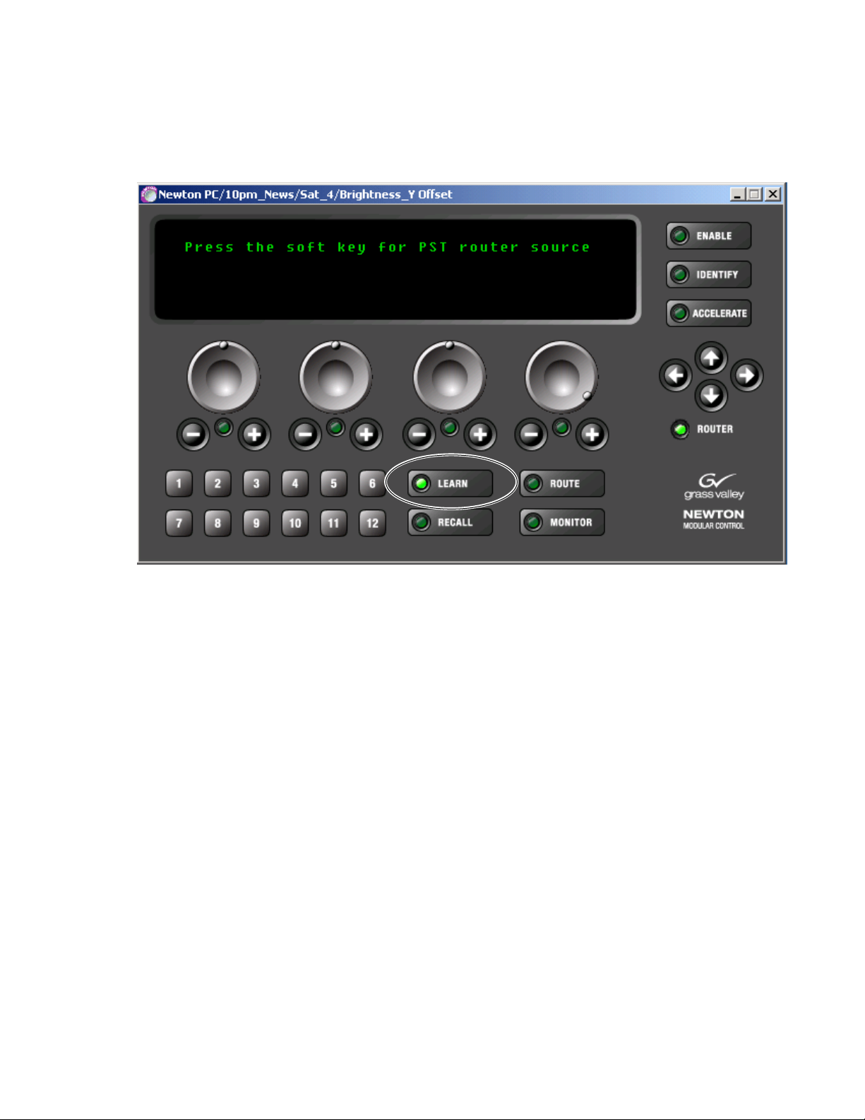
Newton Panel Description
3. Press the Learn button to the right of the soft keys. The display will
instruct you to
Figure 86. Delegate Soft Key to Router Source at Software Panel
Press the soft key for PST router source (Figure 86).
4. Press the desired soft key to assign to this router source. The display
will return to the Preset Source mode.
5. Select a different router source, then press the Recall button and the soft
key to verify the correct router source is recalled.
Newton Instruction Manual 99
Page 100

Section 4 — Operation
V
Video
In Gain
HTimg
Video
Timing
Bright
Y OFF
Rack Mount Panel – Soft Key Router Source Assignment
To make soft key source assignments from the rack mount panel:
1. On the Newton rack mount panel (Figure 87), select the Route button to
bring up the Preset Source mode.
2. Rotate the fourth knob (yellow LED) to bring up the preset source (in
brackets) you wish to delegate to a soft key.
3. Assign this displayed source to a soft key by holding down the
Learn/Recall button until the display shows the Press the soft key for PST
router source message (not shown).
Figure 87. Delegate Router Source to Soft Keys at Rack Mount Panel
NEWTON
MODULAR CONTROL
Learn/
Recall
Route
Mon
Router
Monitored Dest:
SRC
[ Monitoring PST ]
DEST
SRC11
Dst1
Dst11
D_DST_2
[ PST SRC ] [ SRC20 ]
[ Dst12 ]
[D_DST_2]
Enable
Ident
8234_00_12
Learn button
Route button
Rotate third knob with yellow LED
4. Press the desired soft key to assign to this router source. The display
will return to the Preset Source mode.
5. Select a different router source, then press the Recall button and the soft
key to verify the correct router source is recalled.
100 Newton Instruction Manual
 Loading...