

Page 1

NetConfig
NETWORKING CONFIGURATION APPLICATION
Instruction Manual
Software Version 2.0.12
071819003
AUGUST 2010
Page 2

Affiliate with the N.V. KEMA in The Netherlands
CERTIFICATE
Certificate Number: 510040.001
The Quality System of:
Thomson Inc, and its worLdwide Grass Valley division affiliates DBA
GRASS VALLEY
Headquarters
400 Providence Mine Rd
Nevada City, CA 95959
United States
15655 SW Greystone Ct.
Beaverton, OR 97006
United States
10 Presidential Way
Suite 300
Woburn, MA 01801
United States
Kapittelweg 10
4827 HG Breda
The Nederlands
7140 Baymeadows Way
Ste 101
Jacksonville, FL 32256
United States
2300 So. Decker Lake Blvd.
Salt Lake City, UT 84119
United States
Rue du Clos Courtel
CS 31719
35517 Cesson-Sevigné Cedex
France
1 rue de l’Hautil
Z.I. des Boutries BP 150
78702 Conflans-Sainte
Honorine Cedex
France
Technopole Brest-Iroise
Site de la Pointe du Diable
CS 73808
29238 Brest Cedex 3
France
40 Rue de Bray
2 Rue des Landelles
35510 Cesson Sevigné
France
Spinnereistrasse 5
CH-5300 Turgi
Switzerland
Brunnenweg 9
D-64331 Weiterstadt
Germany
Carl-Benz-Strasse 6-8
67105 Schifferstadt
Germany
Including its implementation, meets the requirements of the standard:
ISO 9001:2008
Scope:
The design, manufacture and support of video and audio hardware and software products and
related systems
.
This Certificate is valid until: June 14, 2012
This Certificate is valid as of: June 14, 2009
Certified for the first time: June 14, 2000
H. Pierre Sallé
President
KEMA-Registered Quality
The method of operation for quality certification is defined in the KEMA General Terms
And Conditions For Quality And Environmental Management Systems Certifications.
Integral publication of this certificate is allowed.
KEMA-Registered Quality, Inc.
4377 County Line Road
Chalfont, PA 18914
Ph: (215)997-4519
Fax: (215)997-3809
CRT 001 073004
Accredited By:
ANAB
Page 3

NetConfig
NETWORKING CONFIGURATION APPLICATION
Instruction Manual
Software Version 2.0.12
071819003
AUGUST 2010
Page 4
Contacting Grass Valley
International
Support Centers
Local Support
Centers
(available
during normal
business hours)
France
24 x 7
Australia and New Zealand: +6
Middle East: +9
Europe
+800 8080 2020 or +33 1 48 25 20 20
Hong Kong, Taiwan, Korea, Macau: +852 2531 3058 Indian Subcontinent: +91 22 24933476
Asia
Southeast Asia/Malaysia: +6
China: +8
Belarus, Russia, Tadzikistan, Ukraine,
S. Europe/Italy-Roma: +3
Benelux/Belgium: +3
Germany, Austria, Eastern Europe: +4
61 0660 159 450 Japan: +81 3 5484 6868
71 4 299 64 40 Near East and Africa: +800 8080 2020 or +33 1 48 25 20 20
Copyright © Grass Valley, Inc. All rights reserved.
This product may be covered by one or more U.S. and foreign patents.
Grass Valley Web Site
The www.grassvalley.com web site offers the following:
Online User Documentation — Current versions of product catalogs, brochures,
data sheets, ordering guides, planning guides, manuals, and release notes
in .pdf format can be downloaded.
FAQ Database — Solutions to problems and troubleshooting efforts can be
found by searching our Frequently Asked Questions (FAQ) database.
Software Downloads — Download software updates, drivers, and patches.
United States/Canada
24 x 7
03 7805 3884 Southeast Asia/Singapore: +65 6379 1313
1 1300 721 495 Central/South America: +55 11 5509 3443
Uzbekistan: +7 095 2580924 225 Switzerland: +41 1 487 80 02
9 06 87 20 35 28 -Milan: +39 02 48 41 46 58 S. Europe/Spain: +34 91 512 03 50
2 (0) 2 334 90 30 Benelux/Netherlands: +31 (0) 35 62 38 42 1 N. Europe: +45 45 96 88 70
9 6150 104 444 UK, Ireland, Israel: +44 118 923 0499
+1 800 547 8949 or +1 530 478 4148
4 NetConfig — Instruction Manual
Page 5

Contents
NetConfig . . . . . . . . . . . . . . . . . . . . . . . . . . . . . . . . . . . . . . . . . . . . . . . . . . . . . . . . . . . . . . . . . . 7
Introduction . . . . . . . . . . . . . . . . . . . . . . . . . . . . . . . . . . . . . . . . . . . . . . . . . . . . . . . . . . . 7
NetConfig Features . . . . . . . . . . . . . . . . . . . . . . . . . . . . . . . . . . . . . . . . . . . . . . . . . . . 7
NetConfig Scope . . . . . . . . . . . . . . . . . . . . . . . . . . . . . . . . . . . . . . . . . . . . . . . . . . . . . 8
Important Security Information . . . . . . . . . . . . . . . . . . . . . . . . . . . . . . . . . . . . . . . . 9
Device Software Load Background Information . . . . . . . . . . . . . . . . . . . . . . . . . . 9
Before You Start. . . . . . . . . . . . . . . . . . . . . . . . . . . . . . . . . . . . . . . . . . . . . . . . . . . . . . . 10
Hardware and Software Requirements . . . . . . . . . . . . . . . . . . . . . . . . . . . . . . . . . 10
Windows 7 Requirements. . . . . . . . . . . . . . . . . . . . . . . . . . . . . . . . . . . . . . . . . . . 10
Installing NetConfig . . . . . . . . . . . . . . . . . . . . . . . . . . . . . . . . . . . . . . . . . . . . . . . . . . . 11
Plug-In Licensing. . . . . . . . . . . . . . . . . . . . . . . . . . . . . . . . . . . . . . . . . . . . . . . . . . . . 11
NetConfig Versions. . . . . . . . . . . . . . . . . . . . . . . . . . . . . . . . . . . . . . . . . . . . . . . . . . 11
NetConfig Installation Procedure . . . . . . . . . . . . . . . . . . . . . . . . . . . . . . . . . . . . . . 12
NetConfig Shortcut . . . . . . . . . . . . . . . . . . . . . . . . . . . . . . . . . . . . . . . . . . . . . . . . . . 15
NetConfig PC Configuration with Two NICs. . . . . . . . . . . . . . . . . . . . . . . . . . . . 16
Setting Default Gateway . . . . . . . . . . . . . . . . . . . . . . . . . . . . . . . . . . . . . . . . . . . . 16
Using NetConfig . . . . . . . . . . . . . . . . . . . . . . . . . . . . . . . . . . . . . . . . . . . . . . . . . . . . . . 17
Device Discovery . . . . . . . . . . . . . . . . . . . . . . . . . . . . . . . . . . . . . . . . . . . . . . . . . . . . 19
Network Views . . . . . . . . . . . . . . . . . . . . . . . . . . . . . . . . . . . . . . . . . . . . . . . . . . . . . 19
Expanding Branches . . . . . . . . . . . . . . . . . . . . . . . . . . . . . . . . . . . . . . . . . . . . . . . 20
Device Status. . . . . . . . . . . . . . . . . . . . . . . . . . . . . . . . . . . . . . . . . . . . . . . . . . . . . . 21
Copy Function . . . . . . . . . . . . . . . . . . . . . . . . . . . . . . . . . . . . . . . . . . . . . . . . . . . . 22
Identifying A Device . . . . . . . . . . . . . . . . . . . . . . . . . . . . . . . . . . . . . . . . . . . . . . . 22
Device Properties . . . . . . . . . . . . . . . . . . . . . . . . . . . . . . . . . . . . . . . . . . . . . . . . . . 22
Accessing Device Web Pages. . . . . . . . . . . . . . . . . . . . . . . . . . . . . . . . . . . . . . . . . . 23
Web Address (URL) Field . . . . . . . . . . . . . . . . . . . . . . . . . . . . . . . . . . . . . . . . . . . . 24
About (NetConfig). . . . . . . . . . . . . . . . . . . . . . . . . . . . . . . . . . . . . . . . . . . . . . . . . . . 24
Refresh Browser. . . . . . . . . . . . . . . . . . . . . . . . . . . . . . . . . . . . . . . . . . . . . . . . . . . . . 24
Using The Facility View . . . . . . . . . . . . . . . . . . . . . . . . . . . . . . . . . . . . . . . . . . . . . . 25
Creating/Inserting New Tree Branches in Facility View . . . . . . . . . . . . . . . . 25
Renaming Tree Branches in Facility View . . . . . . . . . . . . . . . . . . . . . . . . . . . . . 26
Deleting Tree Branches or Devices in the Facility View . . . . . . . . . . . . . . . . . 26
Placing Devices in the Facility View . . . . . . . . . . . . . . . . . . . . . . . . . . . . . . . . . . 26
Rearranging Devices in the Facility View . . . . . . . . . . . . . . . . . . . . . . . . . . . . . 26
Associating a Branch in Facility View with a User-Defined Link . . . . . . . . . 26
Inventory Function . . . . . . . . . . . . . . . . . . . . . . . . . . . . . . . . . . . . . . . . . . . . . . . . . . 27
Export to Excel . . . . . . . . . . . . . . . . . . . . . . . . . . . . . . . . . . . . . . . . . . . . . . . . . . . . 29
Export as CVS. . . . . . . . . . . . . . . . . . . . . . . . . . . . . . . . . . . . . . . . . . . . . . . . . . . . . 30
Keystroke Shortcuts . . . . . . . . . . . . . . . . . . . . . . . . . . . . . . . . . . . . . . . . . . . . . . . . . 30
Configuring Devices Using NetConfig . . . . . . . . . . . . . . . . . . . . . . . . . . . . . . . . . 30
Setting IP Addresses . . . . . . . . . . . . . . . . . . . . . . . . . . . . . . . . . . . . . . . . . . . . . . . 31
Resolving Duplicate IP Addresses . . . . . . . . . . . . . . . . . . . . . . . . . . . . . . . . . . . 34
Loading Device Software . . . . . . . . . . . . . . . . . . . . . . . . . . . . . . . . . . . . . . . . . . . 34
NetConfig Options . . . . . . . . . . . . . . . . . . . . . . . . . . . . . . . . . . . . . . . . . . . . . . . . . . . . 37
Health Checker . . . . . . . . . . . . . . . . . . . . . . . . . . . . . . . . . . . . . . . . . . . . . . . . . . . . . 37
NetConfig — Instruction Manual 5
Page 6

Contents
Device Identification . . . . . . . . . . . . . . . . . . . . . . . . . . . . . . . . . . . . . . . . . . . . . . . . 38
Tool Bar Views . . . . . . . . . . . . . . . . . . . . . . . . . . . . . . . . . . . . . . . . . . . . . . . . . . . . . 39
Views . . . . . . . . . . . . . . . . . . . . . . . . . . . . . . . . . . . . . . . . . . . . . . . . . . . . . . . . . . . . . 39
NetConfig Plug-Ins . . . . . . . . . . . . . . . . . . . . . . . . . . . . . . . . . . . . . . . . . . . . . . . . . . . 40
Index. . . . . . . . . . . . . . . . . . . . . . . . . . . . . . . . . . . . . . . . . . . . . . . . . . . . . . . . . . . . . . . . . . . . . . 41
6 NetConfig — Instruction Manual
Page 7

NetConfig
Introduction
NetConfig (Networking Configuration Application) is a multipurpose software component for managing NetConfig-enabled Grass Valley devices.
Grass Valley products that currently use NetConfig include:
• Kameleon and Gecko Modules and Newton Panels,
• Encore and Prelude Routing Systems,
• M-2100 Mini Master Control Panel,
• Grass Valley Camera CCUs,
• Kayenne Switchers, and
• Kalypso and Zodiak Switcher Remote Aux Panels.
As Grass Valley develops new product this list will grow.
NetConfig Features
The NetConfig application is designed to make network configuration
simple.
• NetConfig discovers devices on the network, and these devices can
have their IP addresses configured remotely using the PC on which
NetConfig has been installed,
• NetConfig reports duplicate IP addresses, which can be easily resolved,
• NetConfig is used to install software to these devices,
• NetConfig can be used to identify devices, by blinking their LEDs or
panel buttons,
• NetConfig incorporates a web browser that displays web pages served
by the devices on the network,
• NetConfig provides rudimentary health checks of these devices, and
• NetConfig provides inventory tools for equipment management.
Application specific NetConfig plug-ins are also available for use with
various Grass Valley products (for example, Newton and Prelude). Each
plug-in provides special functionality for that product.
NetConfig — Instruction Manual 7
Page 8
NetConfig Scope
Hub
8190_01_r0
Control Panel
Control Panel
Control Panel
Control Panel
Control Panel
Control Panel
Control Panel
Control Panel
Ethernet
Switch
Ethernet Router
(default Gateway address)
Board 1
Board 2
Board 3
Board 4
Ethernet
Switch
Uplink
Broadcast Message
Response Message
Encore
Controller
with Relay Agent
8900 Modular
Frame
with Net Card
Ethernet
Switch
Ethernet
Switch
NetConfig
PC
Via Uplink or
Relay Agent all
Control Panels
are on the same
Network and respond
to NetConfig.
NetConfig sends
Broadcast Discovery
messages and sees
devices that respond.
Router may or may not
be configured with
IP Helper to pass
Broadcast messages.
Net Card in
Modular Frame
responds and
relays Board
statuses to
NetConfig
Control Panels are
NOT seen by NetConfig
unless default Gateway
Router is using IP Helper.
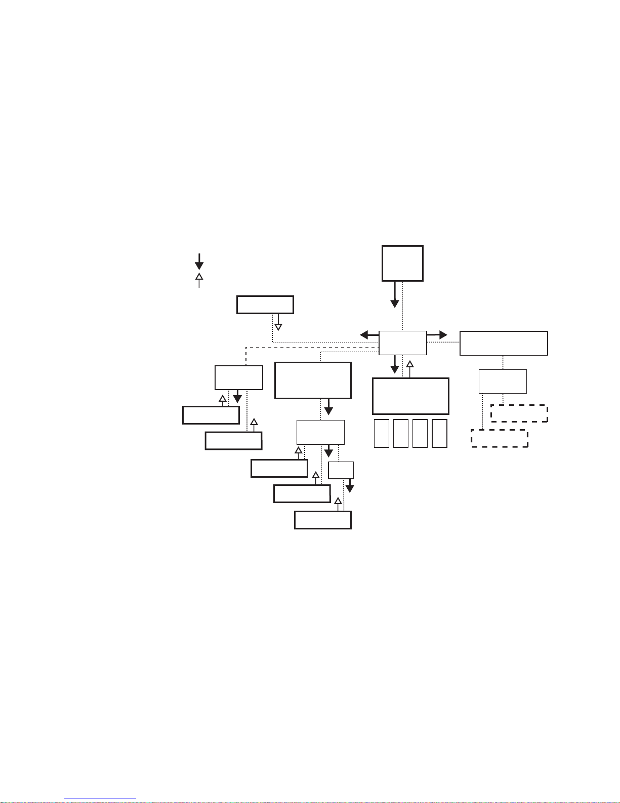
The NetConfig application uses a client-server model. The NetConfig
application acts as the server and sends out Requests to client devices,
which send Responses.
Introduction
The NetConfig discovery process employs
Ethernet broadcast messages.
This process works only when the NetConfig-enabled devices are on the
same LAN; that is, either connected directly, or connected via a hub or
switch. Broadcast messages do not normally propagate through router
gateways, so devices on a WAN are not normally discovered (see Figure 1).
Figure 1. Network Topology and Broadcast Messages
NetConfig — Instruction Manual 8
Note We generally recommend using unmanaged switches, instead of hubs, on
On some routers, IP Helper can be enabled to propagate broadcast messages. These messages are then sent as subnet broadcasts for a particular
port.
will receive and respond to broadcast messages. However, if the device is
completely unconfigured or misconfigured, it will not receive the broadcast
message even if IP Helper is enabled.
networks. A hub may be used with a single device to extend beyond the
Ethernet 100 meter limit. We do not recommend attaching multiple devices
to a hub since this commonly introduces Ethernet message collisions that
can affect overall system performance.
If a device is configured on a subnet that matches IP Helper, then it
Page 9

In summary, NetConfig works on a flat, isolated LAN without the need for
special network configuration. To work properly in any other network
topology, network system configuration outside the scope of this manual
may be required. Work with your network administrator if you wish to use
NetConfig in other network environments.
Important Security Information
The NetConfig application is a powerful tool. A NetConfig user can easily
change the IP addresses of NetConfig compliant devices on a network, and
can change the software installed on those devices. For responsible facility
engineering staff these capabilities are extremely useful for bringing up and
configuring systems. A person with malicious intent, however, can use
these same capabilities to take any or all NetConfig compliant devices on
the network offline, possibly seriously disrupting facility operations.
It is assumed that those using NetConfig are indeed legitimate authorized
users, and are working in premises which are physically secure/restricted
and protected from extraneous network penetration, either by physical iso
lation or behind a company firewall.
Introduction
-
Device Software Load Background Information
NetConfig can be used by several different Grass Valley product lines to
load software to various devices over the network. The same NetConfig
application software is used by all the product lines, but different kinds of
device software will need to be loaded to different devices. Identifying
what type and version of software is available to NetConfig to load is
accomplished using separate files included with each specific product line
release. These files provide NetConfig paths to the locations of the software
appropriate for each device. Only the path and software files for that par
ticular product line will be included in the NetConfig software bundled
with that product’s software releases. These files are installed onto the PC
along with the NetConfig application itself.
In earlier versions of NetConfig, files appended with .sw3 were used to
identify the type and location of device software. In newer versions, .xml
files are used. NetConfig supports either or both mechanisms. The organi
zational tree structure displayed by NetConfig from which you choose
which software version to load is determined by these files.
For example, if you install the NetConfig application provided with one
product, and then install NetConfig provided with a different product, the
new product’s .xml or .sw3 files are simply added to that PC, and do not
overwrite files of the other product line. NetConfig can still load the other
product’s software to those devices. The software load tree structure will
show both the new product line device software and the previous product
line device software.
-
-
NetConfig — Instruction Manual 9
Page 10

Before You Start
Hardware and Software Requirements
Before You Start
NetConfig presumes some degree of customer-furnished equipment (CFE)
and software in order to complete the system. This equipment typically
includes one or more personal computers (PCs), an Ethernet switch or
switches, and category 5 UTP Ethernet cabling with RJ-45 connectors.
You can run NetConfig on the PC or one of the PCs already running other
Grass Valley software for your system. Alternatively, you can run Net
Config on a separate PC connected to your Grass Valley network.
Depending on the system deployed, the PC can be used to accomplish
many tasks. These tasks range from running a simple client application to
complete control and configuration of an entire system.
To run NetConfig you will need:
• Windows 2000 SP4, Windows XP SP2, or Windows 7 and above oper-
ating system,
-
• to be logged in with Administrator-level privileges for the local
machine, and
• have Internet Explorer version 5.5 or later installed.
Windows 7 Requirements
If your PC is running Windows 7, opening the NetConfig application by
clicking the shortcut may display an error message:
abled, which indicates the application needs administrator access. This can
be accomplished in various ways”
Permanent Application Administrator Access
• Right click on the program shortcut, then click on Properties and on the
Compatibility tab, check the Run this program as an administrator box, and then
click
OK.
-or-
• Right click on the program shortcut, then click on Properties. Click on the
Shortcut tab for a program shortcut, then click on the Advanced button.
Check the
Run as an administrator box, and then click OK.
Health check pings dis-
Current Session Only Administrator Access
• Right click on the program shortcut or program .exe file, and click on
NetConfig — Instruction Manual 10
Run as administrator.
Page 11

Installing NetConfig
NetConfig can be purchased as a separate option, or it may be bundled
with individual Grass Valley product software. If bundled, refer to the software installation instructions provided w
(typically a Software Release Note or Instruction Manual).
CAUTION After NetConfig installation, do not delete any files under the directory where
Plug-In Licensing
Some NetConfig plug-ins for specific products employ a licensing key
mechanism. Each license key is associated with a particular PC, and separate keys will need to be purchased for each NetConfig computer
tion that will employ that plug-in. The licensing keys only apply to plug-in
nctionality. The NetConfig application itself can be installed onto any
fu
computer and its basic functionality will be fully operational.
Installing NetConfig
ith that Grass Valley product
the NetConfig tool resides. This may lead to abnormal behavior of the tool.
installa-
NetConfig Versions
If you already have NetConfig installed on your computer, you can check
its version information by clicking
The NetConfig installer replaces any older version of
already reside on your PC. You do not need to uninstall any older versions
first. A version checking mechanism has been implemented that prevents
overwriting newer NetConfig software with an older version.
Note Always select the NetConfig check box when installing bundled software to
About button on the NetConfig toolbar.
NetConfig that may
get the latest version of NetConfig, which may be required to support necessary plug-ins.
NetConfig — Instruction Manual 11
Page 12
NetConfig Installation Procedure
Note Bundled versions of NetConfig may have different installation screens. A
menu with check boxes may be displayed that allows you to choose which
components to install. Refer to the documentation provided with that product
for specific installation instructions.
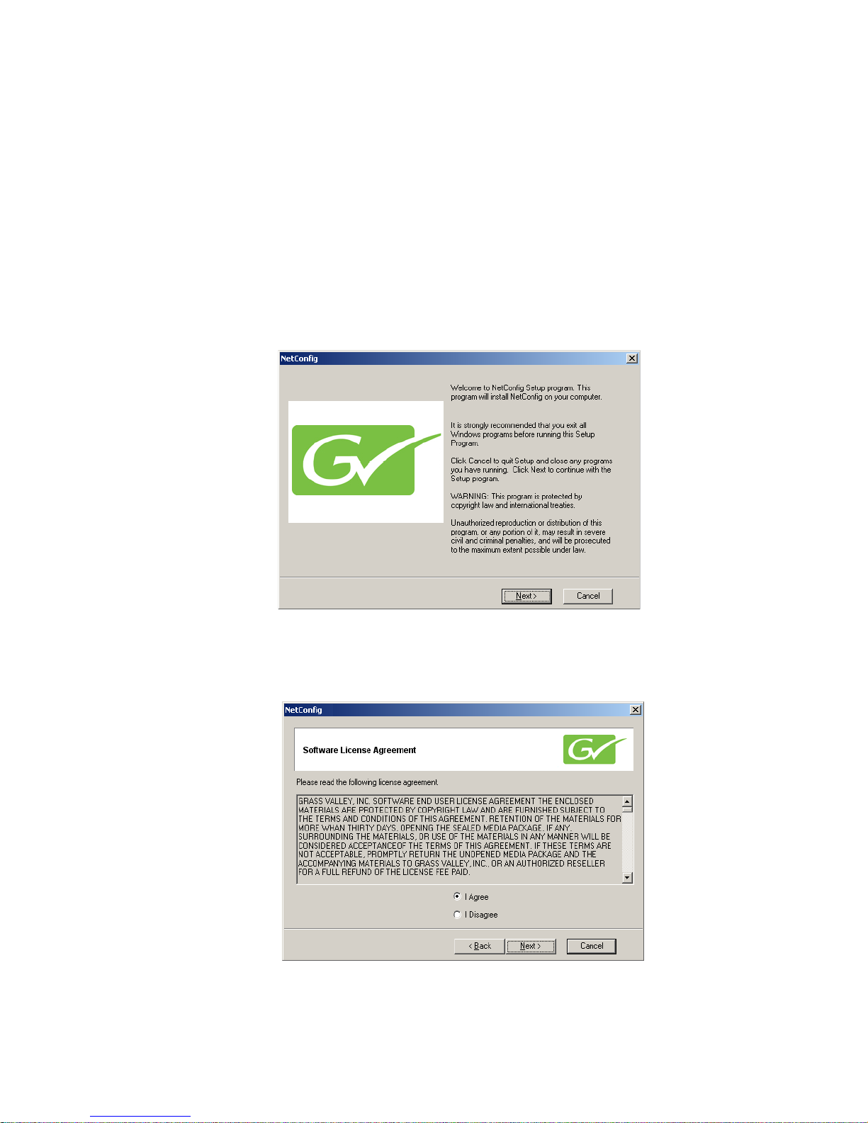
1. Insert the NetConfig CD-ROM into the CD drive in your networked
PC. The setup application should autorun when inserted. If not, locate
the Setup.EXE file on the CD and double-click on it to start the
installation. The Welcome screen is displayed (Figure 2).
Figure 2. Installation Welcome Screen
Installing NetConfig
2. Click Next >. The License Agreement screen is displayed (Figure 3).
Figure 3. License Agreement Screen
NetConfig — Instruction Manual 12
Page 13
Installing NetConfig
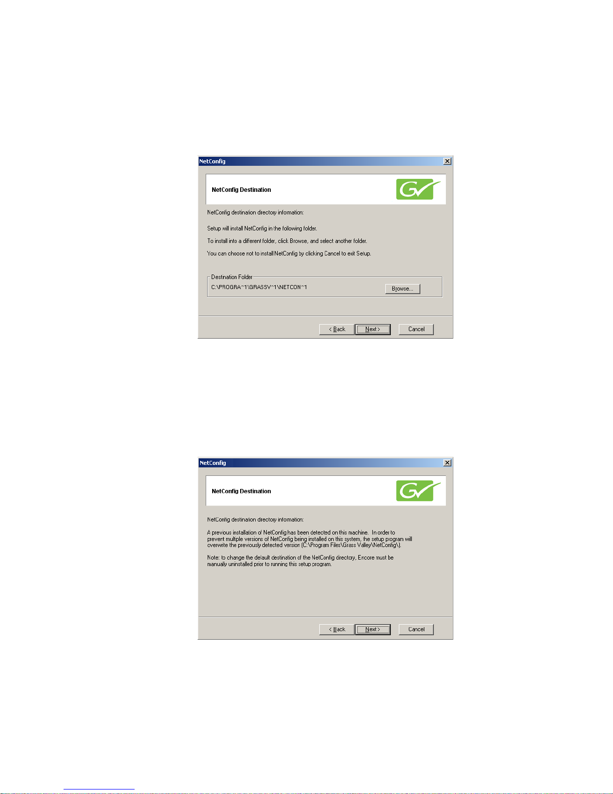
3. Read the license agreement and click on the I Agree radio button, then
Next > button to continue. (Pressing the I Disagree button will halt the
the
install.) If NetConfig has not previously been installed, a Destination
screen appears allowing you to choose a folder location (Figure 4).
Figure 4. Installation Destination Location
• If an older version of NetConfig already exists on the PC, you will
not be allowed to choose a different location. This prevents
installing multiple versions of NetConfig on the same PC. The
screen displayed indicates the existing NetConfig application will
be overwritten (Figure 5).
Figure 5. Installation Destination of Previous Installation
Note If a newer version of NetConfig already exists at the installation destination,
NetConfig — Instruction Manual 13
a message will be displayed that prevents you from overwriting the newer
version with the older version. If this occurs when using a product software
CD, unselect NetConfig and install only the product specific files. You will not
need to re-install NetConfig since a newer version is already present.
Page 14
Installing NetConfig
4. Selecting the default destination (as shown in Figure 4 on page 13) is
recommended. Alternative
another folder. When finished, select the
screen appears (Figure 6).
Figure 6. Install Shortcut Message
ly you can use the Browse button to select
Next > button. The Shortcut
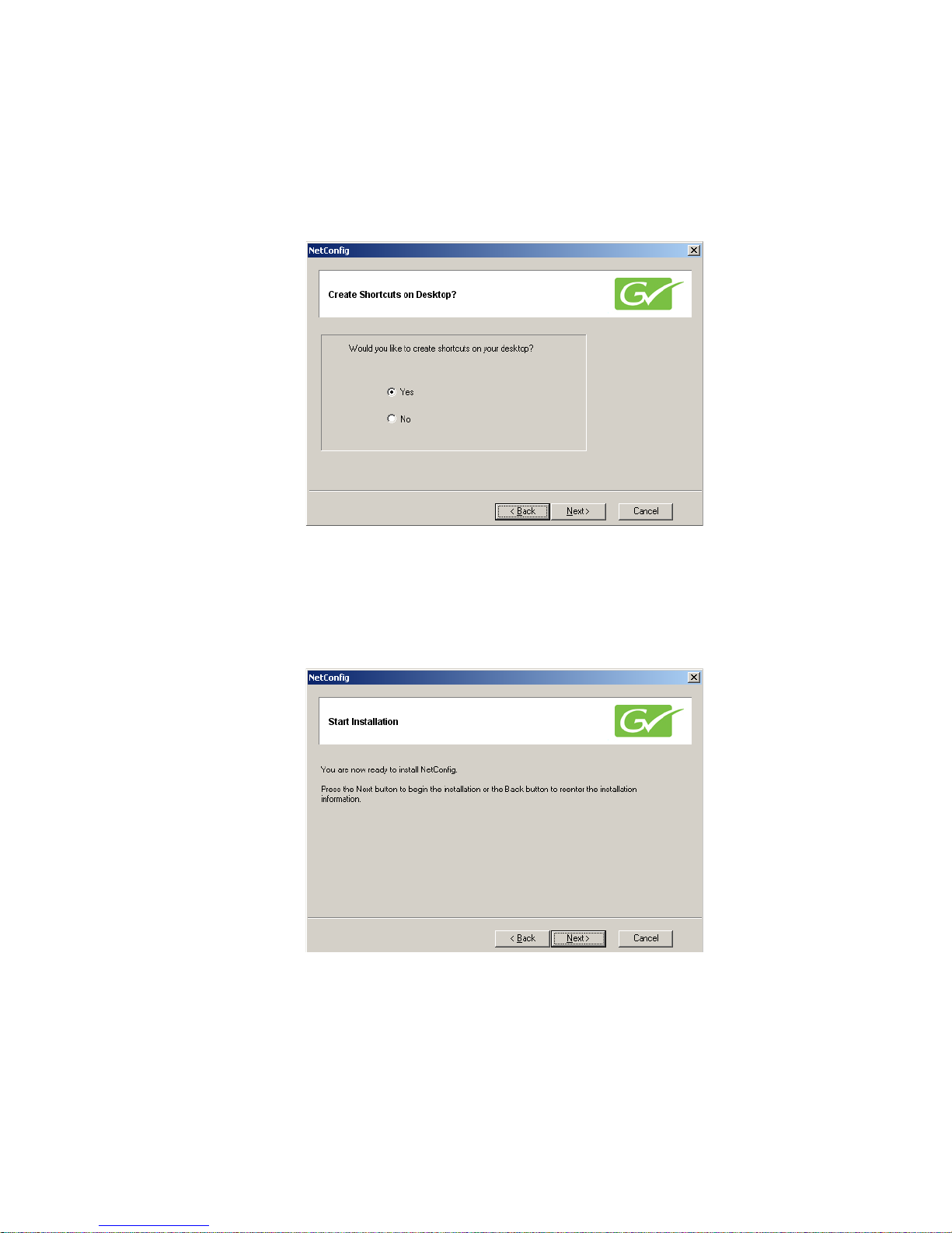
5. Choose whether or not you wish to install a NetConfig shortcut on the
desktop and then select the
appears The Start screen appears(Figure 7),
Figure 7. Installation Start Screen
Next > button (Figure 6). The Start screen
NetConfig — Instruction Manual 14
Page 15

Installing NetConfig
6. Select the Next > button to begin the installation. The Installing progress
screen will be displayed (Figure 8).
Figure 8. Installation Progress Screen
7. Once installation is completed and successful, a Finish screen will be
displayed (Figure 9).
Figure 9. Installation Finish Screen
8. Press the Finish > button to exit.
NetConfig Shortcut
A shortcut to NetConfig will be automatically installed on the PC desktop
if that option was chosen. The NetConfig shortcut ic
NetConfig — Instruction Manual 15
on is illustrated at left.
Page 16

NetConfig PC Configuration with Two NICs
If NetConfig does not discover the devices you expect to see on a PC which
has two or more Network Interface Cards (NICs), this may indicate you
need to change the setting of the default gateway for the PC.
NetConfig sends broadcast messages to discover devices on the network
which ar
are sent via the NIC which has the default gateway assigned to it. If the
devices you are expecting to see are on the LAN attached to another NIC,
then you must make that NIC the primary NIC for the PC, so that it's
gateway address is used as the default gateway for the PC.
If you have two or more NICs, use one of the following two methods to
assign the def
Setting Default Gateway
Method 1 - Adapters and Bindings Tab
e then displayed in the IP and Device views. Broadcast messages
ault gateway.
Installing NetConfig
1. On the PC desktop, right-click on My Network Places and select Properties.
2. Select the Advanced selection in the menu and chose Advanced Settings in
the pulldown (Figure 10).
Figure 10. Setting Default Gateway
3. Select the Adapters and Bindings tab (Figure 11).
NetConfig — Instruction Manual 16
Page 17

Using NetConfig
4. In the Connections box, click on the connection you want to broadcast
on. If it is not at the top of the list, use the up arrow to move it to the
top.The device at the top of the list is the default gateway.
Figure 11. Adapters and Bindings Tab
Using NetConfig
Method 2 - Disable and Re-Enable Connection
1. Right-click on My Network Places and select Properties.
2. You should see two connections. Right-click on the connections you
don’t want to broadcast on and select Disable.
The other connection is now the one enabled and it becomes the default
gateway
3. Now enable the other connection. The default gateway will remain on
the correct connection.
You can launch NetConfig a number of ways, but you’ll find it on the Start
menu under Grass Valley Group or an icon will be placed on the desktop
during installation. When you launch NetConfig for the first time (or when
there are no devices connected for the tool to auto-detect and there are no
logical trees under the Facility View previously created by users) the initial
window looks much like it does in Figure 12.
.
NetConfig — Instruction Manual 17
Page 18

Using NetConfig
Discover
Button
View
Buttons
Note The illustration shows the toolbar set to Icon and Text mode. To change the
toolbar icon view, refer to Tool Bar Views on page 39.
Figure 12.
Initial NetConfig Main Screen, No Devices Present
The Discover button is used to detect devices on the network, and the three
View buttons determine how the devices are shown on the screen.
When devices are detected and a view is selected, the left side of the screen
display
s the logical tree of the devices on the network the PC is connected
to (via the Default Gateway assigned to the PC).
The right portion of the screen is the web browser view. When you click a
e in the IP or Device views or a Facility view device with an
devic
embedded link, the home page for that device or the embedded link is displayed in the web browser view (Figure 13).
NetConfig — Instruction Manual 18
Page 19

Figure 13. NetConfig Main Screen, IP View With Device Web Page Displayed
Using NetConfig
Device Discovery
When the NetConifig application starts, it automatically discovers devices
on the network. If at any time you wish to see if any additional device have
been added,
Network Views
Three different network views (IP, Device, and Facility) are available with
NetConfig. Any one or all of the views can be enabled by selecting that
view button in the toolbar at the top of the NetConfig window (Figure 12
on page 18). When selected the views will appear in
views can be expanded or collapsed by clicking
view.
Figure 14. NetConfig Views, Collapsed
press the
Discover toolbar button.
the left window. These
on the box to the left of each
NetConfig — Instruction Manual 19
Page 20

Using NetConfig
The names of all devices connected to the network and their current IP
addresses are listed by IP address under
plays the name and IP address of the local computer r
Select the
menu. Expand the view to see the devices (see Figure 14 on page 19).
The Device View hierarchically lists the categories and types of devices, and
under each device type, the names of each device of that type connected to
the ne
View pulldown menu. The Device view does not display the IP addresses
of the devices.
Figure 15. Device View List
IP View button or the IP View selection in the View pulldown
twork. Select the
Device View button or the Device View selection in the
IP View. The root of the IP view dis-
unning NetConfig.
The Facility View enables you to create custom hierarchical tree structures,
representing the location of various devices in the facility where NetConfig
is being used. Select the
the View pulldown menu. Refer to Using The Facility View on
more information on setting up the Facility view.
Expanding Branches
Any branch can be expanded to show the entire tree structure beneath that
branch by right-clicking it and selecting
appears (Figure 16 on page 21).
Select
Collapse to collapse the tree structure.
Facility View button or the Facility View selection in
page 25 for
Expand on the context menu that
NetConfig — Instruction Manual 20
Page 21

Device Status
The status of each device on the network is shown by use of colored icons.
Icons report the following conditions:
•
•
•
•
•
In the example shown in Figure 16, a device in the Bay 2 8900 Frame has a
problem which is reflected in the top frame level. Expand
show the point of failure. Also in the figure Fred’s Acappella frame is not
communicating (perhaps its Ethernet cable is unplugged). The screen
therefore indicates a failure for the frame, but its boards may still be passing
signals so their status is unknown.
Using NetConfig
Rectangular icons indicate branches on the tree — categories or types of
devices.
Round icons indicate devices — individual devices on the tree.
Green icons, whether branches or devices, indicate proper communica-
tion.
Red icons, whether branches or devices, indicate functional or communi-
cation problems, either at that level in t
thereof.
Gray icons indicate devices with unknown statuses.
he hierarchy or a sublevel
ing the frame will
Figure 16. Device Status and Context Menu Example
NetConfig — Instruction Manual 21
Page 22

Copy Function
Use the Copy function in the context menu shown in Figure 16 to copy a
device and paste it to the Facility View.
Identifying A Device
You can also identify a device on the network using the context menu
opened by right clicking on a device. Clicking on
page 21) will blink board LEDs or control panel
defined period of time (see Device Identification on page 38). This can be
very helpful when multiple devices res
at large facilities where devices may reside at different locations.
Device Properties
Right-clicking on any device in a view will also allow you to select Properties
from the context menu to bring up a Device Properties screen similar to the
one for an 8960ENC modular module shown in Figure 17.
Using NetConfig
Identify Device ( Figure 16 on
buttons of that device for a
ide in the same equipment rack, and
Information for the device such as its location,
number, software version, serial number and other information is reported.
Device status is also shown. The Asset Tag and Location fields can be
updated or assigned with the Inventory function in NetConfig. Refer to
Inventory Function on page 27 for more information.
Figure 17. Device Properties Example
IP Address, description, part
NetConfig — Instruction Manual 22
Page 23

Accessing Device Web Pages
NetConfig provides configuration and monitoring web access. Selecting
the device in the Device View will bring up web pages similar to the one in
Figure 18 for configuring devices on the network.
Using NetConfig
To access the web page of a device, cl
View, Device View or the Facility View. The right side of the main screen
will display the web page for the device.
Figure 18. Product Web Access Configuration
ick the desired device under the IP
The default NetConfig web page (Figure 12 on page 18) will appear in the
Browser view of the main screen if you click:
• The root (the PCs name or I
• The roots of the logical views – IP V
• Any branch which has no devices.
NetConfig — Instruction Manual 23
P number) in the Tree View,
iew, Device View and the Facility
View, or
Page 24

Using NetConfig
If, in the Facility View, you click on a device which doesn’t have an associated link, a no link notice will appear in the web br
Figure 19. Default NetConfig Web Page with No Link Notice
owser (Figure 19).
Web Address (URL) Field
You can use the web address field in the toolbar (Figure 20) to navigate to
other web links.
Figure 20. Web Address (URL) Field
This address bar will automatically refresh to show the current link being
displayed in the Browser View of the main screen. You can type or choose
the link you want, then press
About (NetConfig)
Use this command or it’s toolbar equivalent to learn the version of NetConfig that you’re running.
Refresh Browser
Enter to go to the link.
Click on the Refresh button to refresh the web browser when needed.
NetConfig — Instruction Manual 24
Page 25

Using The Facility View
Use the Facility View to create hierarchical tree structures representing the
location of various devices in the facility wher
For example, if your control panels are in Edit Room 1, the location of the
room is News section, the location of the building is in New York, and New
York is a location for the division/branch of a company called NBC, then
you could create a logical structure under Facility View like the one in
Figure 21.
Figure 21. Facility View Example
Using NetConfig
e you’re using NetConfig.
Creating/Inserting New Tree Branches in Facility View
To insert/add a tree branch to the Facility View, select the branch or category under which the new branch
context menu that appears (Figure 22), choose
inserted and you can type in your label/text for it. Alternately
choose to type in the label for the new device at a later stage, in which case
the new branch would be named New Node.
Figure 22. Context Menu
is to be inserted and right-click. On the
Insert. A new branch will be
, you may
NetConfig — Instruction Manual 25
Page 26

Renaming Tree Branches in Facility View
To rename branches under Facility View, select the one to be renamed and
right-click. On the context menu that appears, choose
Windows fashion, the name is selected and you can type a new or revised
name.
Note Existing devices can not be re-named in the Facility View. They must be
renamed in either the IP or Device View. Changes will be reflected in Facility
View entries for that device.
Deleting Tree Branches or Devices in the Facility View
To delete any of the branches or devices in the Facility View, select the one
to be deleted and right-click. On the context menu, choose
warning window will appear asking for confirmation to delete the selec
tion. If you confirm deletion, the device or selected branch and the devices
(if any) under it will be deleted.
Note Deleting an existing device in the Facility View does not remove or disable the
device.
Using NetConfig
Rename. In standard
Delete. A
-
Placing Devices in the Facility View
To place devices under the desired branch in the Facility View, select and
drag the devices from the IP View or Device View and drop them on the
branch in the Facility View below which they are to be placed. Only devices
can be dragged and dropped into the Facility View. The drag and drop
operation makes a copy of the dragged device(s) under the selected branch.
The device(s) is/are not deleted from the previous location.
Note to drag and drop a device into more than one location in the Facility View, an
error message appears.
Rearranging Devices in the Facility View
Devices can be moved from one location to another within the Facility
View. To move a device from one location to another, drag and drop it in the
new location. Since a device can be in only one location in the Facility View,
it is moved from the previous location to the new location.
Associating a Branch in Facility View with a User-Defined Link
Any branch in the Facility view can be associated with a link to an HTML
page, a GIF file, a JPEG file, or any file with an embedded hyperlink.
To associate a page or file with a branch, right-click it and select Properties
on the context menu that appears. In the Node Link dialog (Figure 23)
which appears use the Browse button to navigate to, and select the HTML
NetConfig — Instruction Manual 26
Page 27

Using NetConfig
page, GIF file, or JPEG file you want to associate with the branch selected
in the Facility View.
Figure 23. Node Link Dialog
This feature can be very useful for linking to such documents as a system
level drawing of a facility done with Visio or any user documentation in
PDF format, for example. Embedded links can be added to these documents and links created to them in the Node Link Dialog box.
When the desired link/file has
that branch. Clicking
properties for the branch. Once a link has been set for a branch, the link will
open in the web browser of the main screen when the associated branch is
selected.
Note Users can associate links only with branches, not with Grass Valley devices
This feature can be used to enter user-defined branches for non-Grass
Valley devices not listed in the logical views and associate them with
appropriate web pages. This enables you to control all of your equipment
from a single control point.
Inventory Function
Selecting the Inventory button or selecting the Show Inventory View selection in the View menu pulldown opens a
of devices on the network on the right side of the window. Deselect the
button to turn off the Inventory function.
been entered, click OK to save and link it to
Cancel will discard any changes to the existing link
in the Facility View.
database view of a complete list
NetConfig — Instruction Manual 27
Page 28

Using NetConfig
The Inventory function gives the following information about each device:
• Name – device name assigned by the user.
• IP Address of the device (frame address
Subnet Mask, Gateway, and EN2 IP data.
• Slot – if the device is a frame module, the frame slot number it is
installed in.
• Class– identifies the device as a frame, panel, or other (module).
• Type – gives a description of the device.
• Asset Tag number – the asset number of the device.
• Location – the user-assigned location of the device.
• Part # and Serial # (if supported by that device).;
• Hardware and Software Revisions.
• MAC address.
Figure 24. Inventory Function
if a module), and, if applicable,
NetConfig — Instruction Manual 28
Page 29

To update a device’s asset and location information, select a device in the
inventory list then the
shown in Figure 25. Update or assign the Asset T
Location and select the
Figure 25. Update Asset Info Screen
Export to Excel
Using NetConfig
Update Asset Info button to bring up the dialog box
ag number and the Device
Send to Device button to save it to the device.
You may export this list to a Microsoft Excel document by selecting the
Export to Excel button. The database information will automatically open
Excel and create a spreadsheet similar to the one shown in Figure 26.
Figure 26. Export To Excel Example
NetConfig — Instruction Manual 29
Page 30
Export as CVS
You can also generate a Comma Separated Variable (CSV) file, suitable for
import into any spreadsheet program, with the
dialog box opens allowing you to name and choose the file save location.
Keystroke Shortcuts
The following keystroke shortcuts are available
•CTRL-C - copy
•CTRL-X - cut
•CTRL-V - paste
• CTRL-E - expand
• CTRL-P - properties
• CTRL-I or INS key - insert (Facility View)
Using NetConfig
Export as CVS button. A
• CTRL-D or DEL key - de
lete (Facility View)
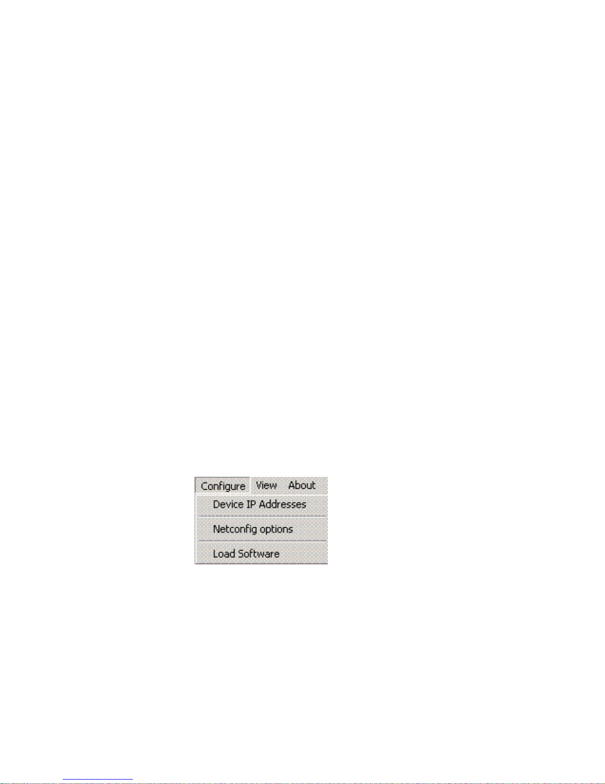
Configuring Devices Using NetConfig
Use the commands on the Configure menu pulldown (Figure 27) or their
corresponding buttons in the toolbar to display IP addresses and other
n
etwork-related information, update device software, or modify Net-
Config options.
Figure 27. Configure Pulldown
NetConfig — Instruction Manual 30
Page 31

Setting IP Addresses
1. Use the Device IP Addresses command on the Configure menu pulldown, or
the corresponding
addresses for any NetConfig compliant devices on your network. The
Change IP Addresses window (Figure 28) will open.
Figure 28. Change IP Addresses Window
Using NetConfig
Set IP button in the toolbar to view or change IP
• Scrolling the inner window to the right reveals additional informa-
tion (Server 1 and 2, if applicable) and an Online field (Figure 29).
Figure 29. Change IP Addresses Window, Scrolled Right
2. If you wish, you can use the Select Device Type pulldown in this window
to specify the kind of devices you want NetConfig to look for.
NetConfig — Instruction Manual 31
Page 32
Using NetConfig
• You can also click on a column heading to sort the list by that
column’s data. Click on the heading again to sort the list in the
opposite direction.
• Clicking the
the contents of the list box dialog.
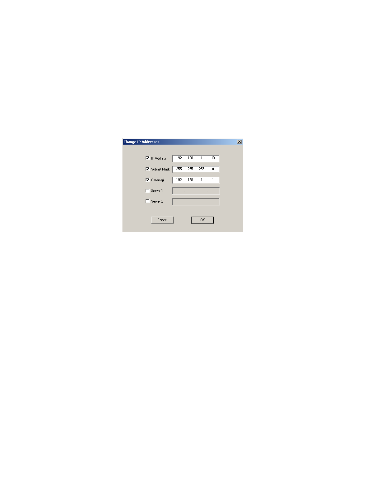
3. Select the device on the list you wish to change by double-clicking its
name, or highlight the device and select the
Change IP Address dialog box (Figure 30).
Figure 30. Change IP Address Dialog Box
The edit boxes in this frame display the IP address, Subnet Mask,
Gateway, and Server 1 and 2 addresses corresponding to the item
selected in the list box.
Re-Discover button at the bottom of the screen refreshes
Edit button to bring up the
Note Selecting multiple devices allows you to change the data for these devices to
the same values in the selected fields. The last octet of each device’s IP
address is retained, however, to prevent duplicate IP addresses. This lets you,
for example, move several devices to a different subnetwork with one action.
4. Checking the boxes on the left activates the edit box and allows you to
change the data.
5. Click OK to enter the new values.
NetConfig — Instruction Manual 32
Page 33

Using NetConfig
Note This does not apply the changes to the selected device(s) yet.
If you attempt to assign an IP Address that is already assigned to
another device on the network, a warning message (Figure 31) will be
displayed.
Figure 31. Duplicate IP Address Warning
6. If this is a valid IP address (not used by another device) a confirmation
screen will come up (Figure 32).
Figure 32. IP Address Confirmation Screen
7. Click Apply Changes to send the modified/updated information to the
clients. This enacts the changes to the device(s).
• Clicking the
made (through the web page or otherwise) to the network parameters of the devices listed and refreshes the list box as well as the Tree
iew in the main NetConfig window.
V
• Clicking the
come on-line.
• Clicking the
clicking on
Status Refresh button also discovers the changes, if any,
Re-Discover button searches for new devices that have
Close button discards the changes made, if any (before
Apply Changes) and exits from the dialog.
NetConfig — Instruction Manual 33
Page 34

Note When the IP address of a Panel is changed manually, the device may initially
be reported as inaccessible (red) even though you committed the changes
and clicked the Refresh button. This is due to the time required for devices
to bind to the new IP address. The status will change back to accessible
(green) on the next polling cycle if the health checker is enabled.
Resolving Duplicate IP Addresses
If a device is installed on the network with the same IP address as another
device, when the new device is discovered, a warning message will indicate that a duplicate IP addr
new devices with factory default IP addresses are installed on the network
(Figure 33).
Figure 33. Duplicate IP Address Message
ess device has been found. This can occur when
Using NetConfig
To resolve the duplicate IP address, go to the Set IP window, ensure All
Devices is selected, and sort the list by IP Address. The devices with duplicate IPs will be listed together. Choose one to
IP address, using the standard IP address configuration procedure
described earlier.
Loading Device Software
Follow these procedures to update existing devices with the latest software.
CAUTION Do not perform these tasks while on the air. The reboot procedure takes your
hardware off-line briefly.
1. Launch NetConfig if it’s not already running.
2. Choose Load Software on the Configure menu or click the Load SW button in
the toolbar.
3. In the dialog box that appears, a hierarchy of folders can be opened for
different products. Navigate to the proper folder and choose the
software and version appropriate for the device(s) you want to update.
A software update package for each device type is required on the PC
before the software will appear in the Software Update window.
change, and give it a unique
NetConfig — Instruction Manual 34
Page 35

Using NetConfig
Note It’s possible that you’ll see devices listed in NetConfig, but not see the appro-
priate software for them in the list or vice
device software that has been loaded on this computer (see Device Software
Load Background Information on
Figure 34. Update Devices Dialog
page 9).
versa. NetConfig displays only the
4. Once you’ve selected a software version, NetConfig lists the devices for
which that software is appropriate in the right pane of the dialog. It also
displays the name, current software version, and IP Address for each of
those devices. In the right pane, check the boxes of all the devices you
want to update.
Note We strongly suggest updating all devices of the same type with the same
software version. To make that easier, you can use the Select All button.
Figure 35. Update Devices Dialog
5. Ensure the Reboot when complete box in the bottom left corner of the
NetConfig — Instruction Manual 35
screen is checked.
Page 36

Using NetConfig
6. Click the Load or Load All button to install the new software in the devices
you’ve selected. A progress pop-up will display the software update
progress.
Figure 36. Software Update Progress
When the software update is complete without error, the message
shown in Figure 37 will appear.
Figure 37. Software Update Complete Message
7. Wait long enough for the devices to reboot, then click the Refresh button
to confirm that your updates are in place.
8. Click the Close button to exit the Update Devices window.
NetConfig — Instruction Manual 36
Page 37

NetConfig Options
NetConfig Options are used to enable/disable checking device communication, set the toolbar view, and define the automatic polling
the devices.
choose the menu option Configure > NetConfig Options, or click the Options
button in the toolbar to open the Configurations Options dialog box
(Figure 38).
Figure 38. NetConfig Options Dialog
NetConfig Options
interval to test
Health Checker
This area is to enable/disable the periodic health check and to configure the
polling time interval for the periodic health check. The polling interval is
set in milliseconds, the default (and recommended) interval being 100 milliseconds.
Depending on the polling interval specified
shown in the tree view will be polled for the health check if a periodic
health check is enabled. If the Network Configuration Tool is unable to
connect to the device, the icon beside the device’s IP address in the tree
view will be shown in red. Otherwise the icon will be displayed as green to
indicate that the device is in good health. When device icons are red in the
Device View, the icons for their entire device family will also be red.
When the check box
user can fill in the polling interval for the periodic health check. This peri-
in the interval, the devices
Perform periodic health check is selected (checked), the
NetConfig — Instruction Manual 37
Page 38

NetConfig Options
odic polling of many devices may cause undesirable network traffic in
some cases.
If this occurs, you can use the Manual Ping function on the toolbar instead to
minimize network traffic. When the
not selected (unchecked) the periodic polling is disabled and the
button will become active.
Perform periodic health check check box is
Manual Ping
Pressing the
are on-line. If a listed device cannot be reached or the device is not accessible, that device’s icon on the tree view
connect failure. The device icon will be green if the device is accessible.
Device Identification
This field sets the duration in seconds that the of LED or buttons of a device
will blank when the Identify Device feature is used (see Identifying A Device
on page 22).
Manual Ping button causes all devices to be polled to see if they
will be shown in red to indicate a
NetConfig — Instruction Manual 38
Page 39

Tool Bar Views
NetConfig Options
The three Tool Bar radio buttons (Figure 38 on page 37) allow you to select
the following options for the toolbar views:
• Icon and Text view – this view shows
panied by text (Figure 39).
Figure 39. Icon and Text Tool Bar View
• Icon Only view – this view shows the NetConfig icons only (Figure 40).
Figure 40. Icon Only Tool Bar View
• Text Only view – this view shows the NetConfig icons as text
(Figure 41).
Figure 41. Text Only Tool Bar View
the NetConfig icons and is accom-
Views
In the Views area of the NetConfig Configurations Options (Figure 38 on
page 37) the numbers of devices detected on the netw
reported.
Clicking on the
of the IP and Device views and re-discover all devices. This updates the
views completely, unlike the
devices discovered.
NetConfig — Instruction Manual 39
ork is dynamically
Clear View and Re-Discover button to erase the entire contents
Discover button which just adds any new
Page 40

NetConfig Plug-Ins
Newton Plug-In Icon Prelude Plug-In Icon
NetConfig plug-ins exist that add product specific features to NetConfig.
Plug-ins are installed using that product’s software CD or downloaded
files, not with the stand-alone NetConfig CD.
Figure 42 shows an example of NetConfig with two plug-ins installed
Newton and Prelude). Icons appear on the toolbar for these products that,
(
when clicked upon, open screens with product specific features. Refer to
the documentation provided with the product for information about these
features.
Figure 42. NetConfig with Plug-Ins Installed
NetConfig Plug-Ins
NetConfig — Instruction Manual 40
Page 41

Index
Symbols
.sw3 file 9
.xml file 9
A
About button 24
administrator privileges 10
Apply Changes button 33
C
Clear and Re-discover button 39
Close button 33
collapse function 20
configuration
with two NIC cards 16
Configure menus 37
copy function 22
expand function 20
Export as CVS 30
Export to Excel button 29
F
Facility View
adding branches 25
associating web link 26
creating and using 25
deleting branches 26
overview 20
placing devices 26
rearranging devices 26
renaming branches 26
Facility View button 20
FAQ database 4
features
of NetConfig 7
frequently asked questions 4
D
device identification
duration 38
device properties
displaying 22
device status
color codes 21
Device Type pulldown 31
Device View
button 20
overview 20
devices detected 39
Discover button 18, 19
documentation online 4
dual NIC cards 16
E
Ethernet broadcast message 8
G
Grass Valley web site 4
H
Health Checker
overview 37
polling time 37
hub
use on network 8
I
Icon and Text view 39
Icon Only view 39
identify device
duration 38
installation 11
procedure 12
NetConfig — Instruction Manual 41
Page 42

Index
Inventory button 27
inventory function 27
Inventory View 27
IP addresses
and red icon 37
resolving duplicates 34
setting 31
setting multiple devices 32
IP Helper 8
IP View
overview 20
IP View button 20
K
keystroke shortcut
shortcut
keystroke 30
L
O
online documentation 4
Options button 37
P
Perform periodic health check 37
plug-in 40
plug-in licensing 11
polling time interval 37
R
Reboot when complete checkbox 35
Re-Discover button 32, 33
Refresh button 24
requirements
hardware and software 10
Windows 7 10
launching NetConfig 17
licensing
of plug-in 11
Load SW button 34
M
main screen
overview 18
Manual Ping button 38
N
NetConfig 7
and network topology 9
bundled software 12
features 7
scope 8
shortcut on desktop 15
NetConfig plug-in 40
Network Configuration Tool 7
network topology 9
network views 19
NIC configuration 16
setting default gateway 16
S
scope of NetConfig 8
security 9
Set IP button 31
setting default gateway
NIC configuration 16
shortcut
NetConfig 15
software
loading with NetConfig 34
software download from web 4
software load
background information 9
sorting colum data 32
Status Refresh button 33
switch
unmanaged 8
T
Text Only view 39
toolbar
Discover button 19
toolbar views 39
42 NetConfig — Instruction Manual
Page 43

U
unmanaged switch 8
Update Asset Info button 29
V
version checking mechanism 11
Views 19
W
web browser view 18
web page access
device
web page access 23
web site documentation 4
web site FAQ database 4
web site Grass Valley 4
web site software download 4
Wide Area Network (WAN) 8
Windows 7
administrator access 10
Index
NetConfig — Instruction Manual 43
Page 44

Index
44 NetConfig — Instruction Manual
 Loading...